
NPCS549 - Audio/video extension Nyrius - Free user manual and instructions
Find the device manual for free NPCS549 Nyrius in PDF.


| Product type | Wireless HDMI audio/video extender |
| Brand | Nyrius |
| Model | NPCS549 |
| Dimensions (L x W x H) | 12 cm x 8 cm x 2.5 cm (transmitter and receiver) |
| Weight | 150 g (each unit) |
| Power supply | 5V DC power adapter (included) |
| Connection type | HDMI 1.4b |
| Maximum resolution | 1080p (1920 x 1080) @ 60 Hz |
| Maximum range | 30 meters (without obstacles) |
| Main features | Wireless audio/video transmission, IR compatible, Plug & Play, low latency |
| Maintenance and cleaning | Wipe with a soft dry cloth. Do not use liquids. |
| Safety | Do not expose to water or excessive heat. Use only the provided adapter. |
| Spare parts and repairability | Spare parts are not available individually. Contact customer service. |
| Warranty | 1 year |
| General information | Country of manufacture: China. Certifications: CE, FCC. |
Frequently Asked Questions - NPCS549 Nyrius
User questions about NPCS549 Nyrius
0 question about this device. Answer the ones you know or ask your own.
Ask a new question about this device
Download the instructions for your Audio/video extension in PDF format for free! Find your manual NPCS549 - Nyrius and take your electronic device back in hand. On this page are published all the documents necessary for the use of your device. NPCS549 by Nyrius.
USER MANUAL NPCS549 Nyrius
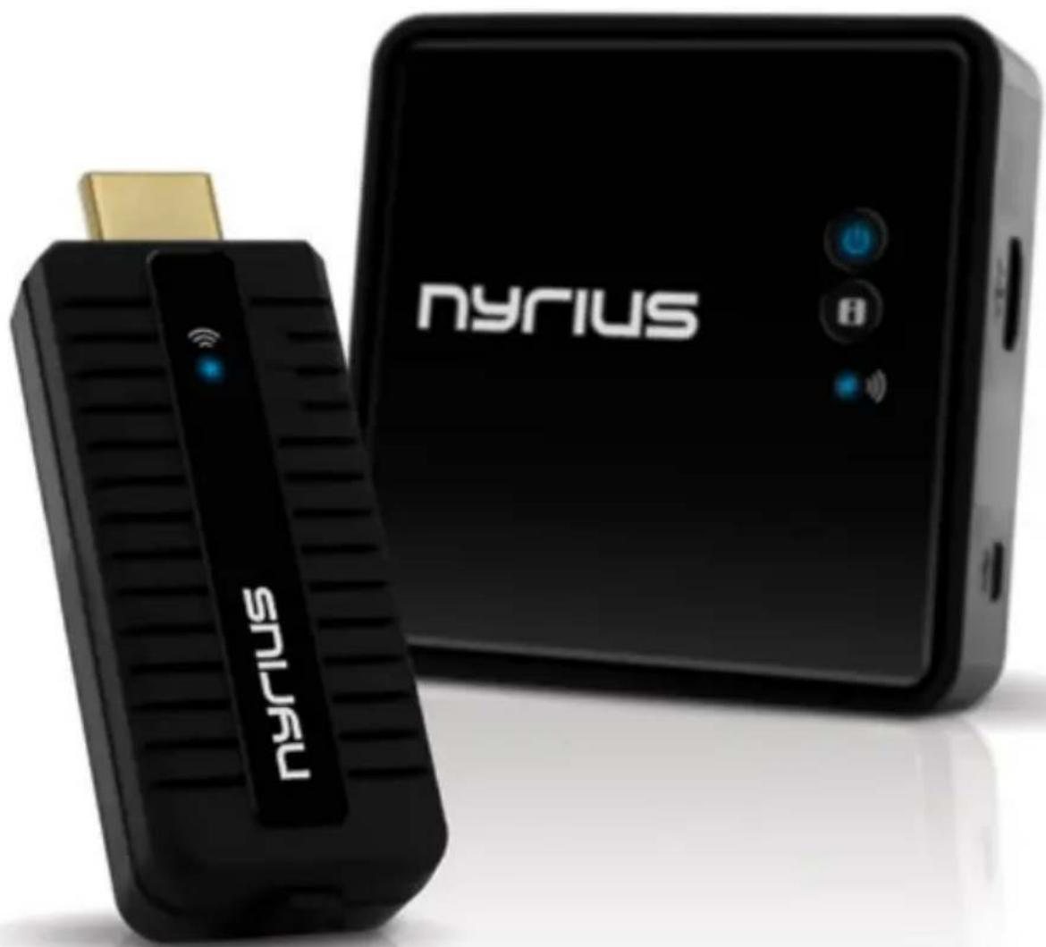
Wireless HD Transmitter
natural_image
Exterior view of a Nyrius device with a USB port and control panel (no readable text or symbols beyond branding)NPCS549
www.NYRIUS.com
Thank you for your purchase of this Nyrius product. Please read this instruction manual carefully before using product to ensure proper use. Keep this manual in a safe place for future reference.
TABLE OF CONTENTS
Table of Contents....2
What's Included ....2
Features 2
Buttons and Connections ....3
Setup 5
Troubleshooting....15
Specifications....16
FCC Statement....17
Safety Information....18
Drilling Template....20
Notes....21
NYRIUS Warranty 22
WHAT'S INCLUDED
• Digital Wireless HD Transmitter
• Digital Wireless HD Receiver
• 2 x 100-240V AC Power Adapter
- 5 ft HDMI® Cable
• Right Angle HDMI® Adapter
- USB Power Cable
• 2 x Screw Anchors
- 2 x Screws
- Instruction Manual
- Quick Start Guide
• 1 Year Warranty
• Lifetime Live Customer Support
FEATURES
- Wirelessly send high definition movies, TV shows, games & music from your PC, Blu-ray™/ DVD player, gaming console or other HDMI® device to an HDTV or projector
- Stream uncompressed, true 1080p video and surround sound audio in real-time with zero latency; 3D compatible
• Powerful 30ft digital signal eliminates the hassle of installing messy cables
- Easy to install plug 'n play setup gets you connected fast; no software required
- Compact flash drive design optimized for laptop use; powered by USB or wall adapter
BUTTONS AND CONNECTIONS
Transmitter - FRONT

Transmitter - SIDE

| 1 | airing button To PAIR transmitter & receiver | |
| 2 | ED Status Indicator | Is a SOLID BLUE colour when the power is ON and has a successful wireless connection |
| 3 | SB Power Input | Connect the transmitter to the desktop or laptop's USB port with the provided USB cable |
| 4 | DMI input | Plug in the Transmitter directly to a PC, cable box or any HDMI device |
BUTTONS AND CONNECTIONS
Receiver - TOP
Receiver - BOTTOM

Receiver - SIDE

| 1 | Power Button with LED indicator | Press to turn the receiver ON and OFF. The indicator in the power button lights up in BLUE when the power is ON, and turns RED in STANDBY MODE. |
| 2 | NFO Button | Press this button to display OSD information on the HDTV screen. |
| 3 | Status LED | Displays the VIDEO STATUS information. |
| 4 | Mounting Holes Allows you to hang the Receiver on the wall. | |
| 5 | C Input Connect to receiver's power adapter. | |
| 6 | DMI Output Connect to HDTV via an HDMI cable. | |
SETUP
CONNECTING THE TRANSMITTER
- Connect the Transmitter directly to a PC, cable box or any HDMI device.
- Connect the Transmitter directly to a PC, cable box or any HDMI device using the USB cable provided or connect the power adapter to the mini USB port of the transmitter and plug it to an available wall outlet.

- You may also connect the Right Angle HDMI® Adapter for easier setup with certain computers.
- The LED indicator on the POWER BUTTON should light up in BLUE when the Transmitter is properly connected to the computer via USB.

natural_image
Laptop keyboard with attached USB port and connector, showing a close-up of the screen (no text or symbols visible)SETUP
MOUNTING THE RECEIVER
-
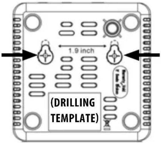
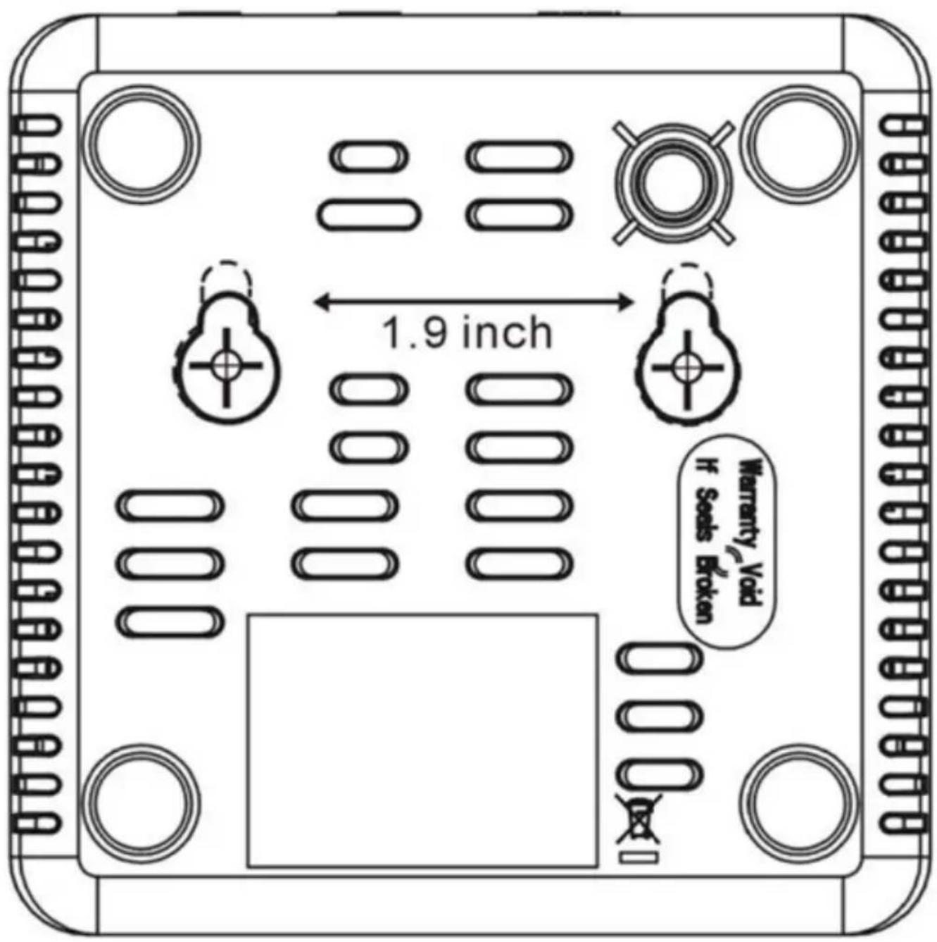
Cut out the DRILLING TEMPLATE on page 19 and tape it to the wall in the location that you would like the Receiver installed.
-
Pre-drill the holes in the marked location.
-
Insert the two supplied Anchors into the pre-drilled holes.

natural_image
Two identical cylindrical objects with dashed lines and circular ends, no text or symbols present-
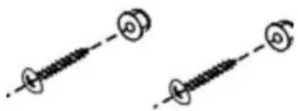
Insert two screws into the anchors and tighten until the screws only stick out about an 1/8 inch away from the wall.
-
Locate the wall mounting holes on the back of the Receiver. Slide the holes over the screws sticking out of the wall to mount into place.
natural_image
Two identical black spiral-shaped lines with circular endpoints, no text or symbols present
natural_image
Technical line drawing of a device rear panel with ports and ventilation slots (no text or symbols)CONNECTING THE RECEIVER TO HDTV
-
Connect the HDMI cable to the HDMI Output of the receiver and to your HDTV television or HD projector.
-
Connect the power adapter to the DC Input of the Receiver and into a wall outlet. When the unit is successfully connected, the Power LED indicator on the POWER button lights up in BLUE.
SETUP
- Once the Transmitter and Receiver are both connected, they will automatically pair to each other.

- When you disconnect the transmitter and the link is disconnected over 10 minutes, the Receiver will enter STANDBY MODE (Power LED of receiver is RED).

SETUP
- Connect the power adapter to the DC Input of the Receiver and into a wall outlet. When the unit is successfully connected, the Power LED indicator on the POWER button lights up in BLUE.
- Once the Transmitter and Receiver are both connected, they will automatically pair to each other.
- During the warm-up period, the POWER LED will flash while BLUE until the signal between the Transmitter and the Receiver is established. It will take approximately 15 \~ 20 seconds to boot-up and establish a link providing everything is operating normally.

natural_image
Diagram showing a laptop connected to a stopwatch and an electronic device via wireless signals (no text or symbols present)- Ensure your TV or projector is powered ON and is in "HDMI input" mode.

SETUP
- If all is operating normally, the POWER LED and INFO/CHANNEL LED will be SOLID BLUE. Please refer to the chart below for detailed LED and OSD transmitter/receiver alert descriptions:
| MODE STATUS | POWER LED | STATUS LED | OSD DISPLAY | |
| STANDBY Power-save mode Solid RED OFF |  | |||
| WARM-UP | During 15-20 second warm-up | Flashing BLUE | Flashing |  |
| SEARCHING CHANNELS | System not able to establish link after 80 seconds (see Notes A and D) | Flashing BLUE | Flashing |  |
| WIRELESS MODE | No input from selected source (See Note B) | Solid BLUE | Flashing quickly |  |
| Video format not recognized (See Note C) | Solid BLUE | Flashing slowly |  | |
| Video format is recognized Solid BLUE | Solid BLUE | - | ||
NOTES
A. If the system is unable to establish a connection within 80 seconds, the connection has been lost or the Transmitter is out of range. Verify the distance between the Transmitter and Receiver. The maximum video transmission range for 1080p content is up to 30ft. in line of sight (LOS). The minimum range is 6.5 ft.
B. Please confirm that the computer is powered ON and that HDMI OUT has been selected; check that HDMI cable is properly connected.
C. If no video is displayed and OSD message states "NOT SUPPORTED FORMAT", then the video frame rate from the computer is NOT supported. See "Supported Resolution" section to change resolutions.
D. If you have more than one pair of each Transmitter/Receiver, each pair should be at least 6.5 feet away from each other. If both pairs of Transmitter/Receiver are in the same room, the suggested the distance between the two is a minimum distance of 6.5 feet.
SETUP
| RECEIVER | ||
| BUTTON OSD Display | ||
| POWER | Press the POWER button on TOP of the receiver to go from " Active mode" to " Active Standby mode". |  |
| INFO | Press the INFO button on TOP of the receiver. The Signal Quality, Source, Channel and Resolution will be displayed on the OSD for your reference. Press the INFO button again to exit. |   |
AUDIO BIT RATE SUPPORT
• Digital Audio from HDMI inputs: Up to 6Mbit/s bit-rate support.
• Support AC3 and DTS.
• 2-Channel PCM audio : 16\~24 bits audio sample with 32\~48KHz sampling rate
| 2 CHANNEL PCM | 32KHZ 44.1KHZ 48KHZ 96KHZ | |||
| 16 Bits | YES YES YES YES | |||
| 24 bits | YES YES YES YES | |||
Windows OS Display setting of Laptop for external display:
Windows7 OS:
- Press key + P key
- There is a POP icon displayed on the screen, as seen below:
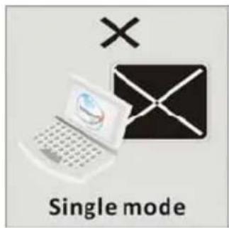


- Select Clone mode, Extend Display or Project out only to enable external display.
SETUP
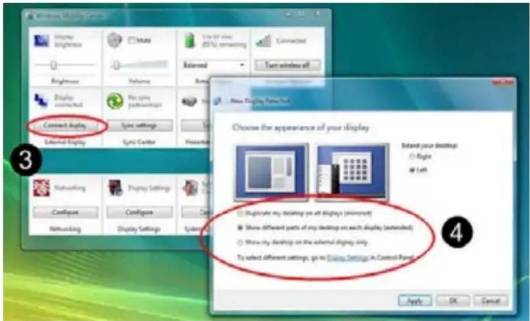
Windows Vista OS:
- Go to START MENU ① in bottom left corner of the screen. Click WINDOWS MOBILITY CENTER ② to open.
- On the EXTERNAL DISPLAY title, click CONNECT DISPLAY ③ to open NEW DISPLAY DETECTED ④.
- Choose MIRRORED or EXTENDED mode to enable external display.

Windows XP OS:
- Right click the mouse on your desktop.
- Click GRAPHIC OPTION / OUTPUT TO.
- Click CLONE MODE or EXTENDED DISPLAY
NOTE: For more information, please type CHANGE DISPLAY SETTINGS in WINDOWS HELP AND SUPPORT.
Mac OS Display setting of Laptop for external display:
• MAC OS will detect external display equipment automatically and switch to a better video resolution when user plugs in the display cable to Apple Mac series.
• Once MAC OS does not detect external display automatically, please check below :
- Click to open DISPLAYS / SYSTEM PERFORMANCE.
- Click DETECT DISPLAYS to detect the external display.
Windows OS Audio setting to switch to HDMI output:
Windows7 OS:
- Go to START MENU in bottom left corner of the screen. Click CONTROL PANEL to open AUDIO setting.
- Select HDMI OUTPUT ① and Press OK ②.

WindowsXP OS:
- Go to START MENU in bottom left corner of the screen. Click CONTROL PANEL to open AUDIO setting.
- Select HDMI OUTPUT and Press OK.
NOTE: For more information, please type CHANGE AUDIO SETTINGS in WINDOWS HELP AND SUPPORT.
SETUP
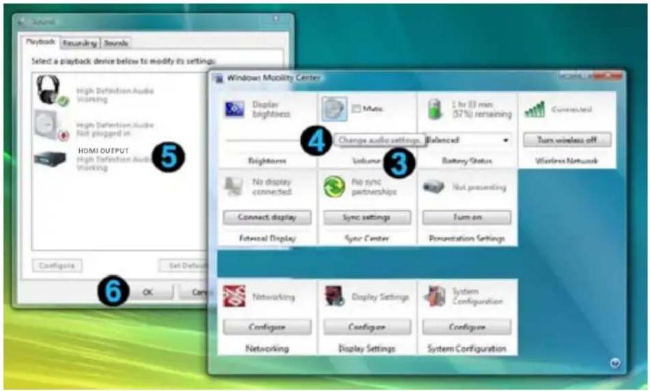
Windows Vista OS:
- Go to START MENU ① in bottom left corner of the screen. Click WINDOWS MOBILITY CENTER ② to open.
- On the VOLUME ③ tab, click the CHANGE AUDIO SETTING ④ icon to open the SOUND section.
- Select HDMI OUTPUT ⑤ and press OK ⑥.

SETUP
SUPPORTED RESOLUTIONS
If the SOURCE LED continues to flash BLUE (slower than "NO SIGNAL" mode); the OSD display shows: 📋, and there is no video displayed or the video quality is poor, it indicates that the video frame rate from your A/V source device is not supported. Ensure that the timing of your HD device is compliant with the standards listed below:
| VIDEO FORMAT TIMING RESOLUTION SUPPORTED | ||
| PRIMARY CEA VIDEO TIMING | ||
| 640X480P @ 59.94 / 60HZ | 480P | YES |
| 720X480P @ 59.94HZ YES | ||
| 720X480P @ 60HZ YES | ||
| 720X576P @ 50HZ 576p YES | ||
| 1280X720P @ 50HZ | 720p | YES |
| 1280X720P @ 59.94 / 60HZ YES | ||
| 1920X1080I @ 50HZ | 1080i | YES |
| 1920X1080I @ 59.94 / 60HZ YES | ||
| 1920X1080P @ 50HZ | 1080p / 60 | YES |
| 1920X1080P @ 59.94 / 60HZ YES | ||
| SECONDARY CEA VIDEO TIMING | ||
| 1920X1080P @ 23.98 / 24HZ | 1080p / 24 | YES |
| 1920X1080P @ 25HZ YES | ||
| 1920X1080P @ 29.97 / 30HZ YES | ||
| VESA TIMING (DVI ONLY) | ||
| 640X480 @ 59.94 / 72.809HZ VGA YES | ||
| 800X600 @ 60.317 / 72.188HZ VGA YES | ||
| 1024X768 @ 60 / 70.069HZ | XGA | YES |
| 1280X768 @ 60 HZ | WXGA | YES |
| 1280X1024 @ 60 HZ | SXGA YES | |
| 1600x1200 @ 60Hz | UXGA | YES |
TROUBLESHOOTING
Before following the troubleshooting guide below please make sure that your Transmitter, Receiver and ANY attached equipment are all properly connected, switched on and not in "Standby Mode".
| Red POWER LED is not lighting up | Make sure the power is connected to the Receiver/Transmitter.Check that the power supplies are connected to a working power outlet.The POWER LED of the Receiver/Transmitter should be BLUE. |
| No Video is displayed | Check the status of the Link LEDs, and check TV or projector are working normally.Check the HDMI cable is undamaged and is plugged into the correct connection.Check that the correct HDMI output has been selected from the TV or projector's menu and that the HDMI cable is plugged into the correct output connection.Make sure that it is the Receiver that is connected to the TV or projector, and the Transmitter that is connected to a PC, cable box or any HDMI device.Verify the Receiver's POWER LED and INFO LED indicators (see chart on page 9).Ensure your video resolution and frame rate is recognized/supported and within the transmission range.Connect the source device to your TV to check and modify the video format compatibility.Check your video resolution with HDMI input from your device is 1080p, 1080i, 720p, 576p, 480p.Ensure the display setting for your PC / Laptop has been switched to Clone Mode, Projector Out Mode or Dual Display Mode to enable external display. |
| Bad Picture | Make sure the HDMI cable used are undamaged and that you can get a good picture when the source is connected directly to the display with an HDMI cable.Check that your video resolution with HDMI input from your PC / Laptop is either 1080p, 1080i, 720p, 576p, or 480p.Ensure the transmission distance is less than 15 feet (LOS). |
| Bad Audio/ No Audio | Make sure that the source is outputting supported audio formats.Make sure that the TV's volume is turned UP and not on MUTE.Make sure that your PC / Laptop audio volume has been turned UP.Make sure that your PC / Laptop audio output has been switched to HDMI out.Make sure there is no 5.8GHz wireless phone within 50cm of the Receiver. Some phones use substandard transmission schemes. |
| Other • If | any other issue occurs or if the above issues persist, try disconnecting both Transmitter and Receiver and repeating the link setup process |
For further questions or inquires, please contact NYRIUS customer support at:
www.nyrius.com/contact
SPECIFICATIONS
| System Requirements | Any laptop or desktop system containing an HDMI port including popular models from these manufacturers: Alienware, Lenovo, Dell, HP, Acer, Apple (Display Port cable not included) | |
| Supported Audio Formats | Digital Audio | up to 6 Mbps AC3 and DTS |
| Supported Video Resolutions | HDMI Input | 1080p, 1080i, 720p, 576p, 480p |
| Transmission Distance | The maximum video transmission range is 15 feet. The minimum range is 6 feet; line of sight (LOS) scenarios | |
| System Latency No latency (<1ms) | ||
| Transmission Frequency | 4.9~5.9GHz (Includes non-DFS and DFS Frequency Bands) | |
| Antenna High Performance Internal Antennas | ||
| Power Supply 100~240V AC in, 5V DC out Power Adapter | ||
| Operating temperature 0°C to 40 °C | ||
| INTERFACES TRANSMITTER RECEIVER | |||
| AV INTERFACES | HDMI Input ONE (Type A, Male) - | ||
| HDMI Output | - | ONE (Type A, Female) | |
| POWER INTERFACE | POWER Input | USB cable or 5V DC input | 5V DC Input |
| SWITCHES | POWER Switch | - | YES (One Tack Switch) |
| INFO Switch | YES (One Tack Switch) | YES (One Tack Switch) | |
| LEDs | POWER LED | - Blue LED or Red LED | |
| STATUS LED | Blue LED | Blue LED | |
| Signal Quality Status | - | OSD displayed | |
| DIMENSIONS | 30(W) X 82.2(L) X 17.5(H) MM | 194.8(W) X 146.8(L) X 31(H) MM | |

This device complies with part 15 of the FCC rules. Operation is subject to the following two conditions:
(1) this device may not cause harmful interference, and
(2) this device must accept any interference received, including interference that may cause undesired operation.
This class B digital apparatus complies with Canadian ICES-003.
WARNING:
This equipment has been tested and is found to comply with the limits for a Class B digital device, pursuant to Part 15 of the FCC Rules. These limits are designed to provide reasonable protection against harmful interference in a residential installation. This equipment generates, uses and can radiate radio frequency energy and, if not installed and used in accordance with the instructions, may cause harmful interference to radio communications. However, there is no guarantee that interference will not occur in a particular installation. If this equipment does cause harmful interference to radio or television reception, which can be determined by turning the equipment off and on, the user is encouraged to try to correct the interference by one or more of the following measures:
• Reorient or relocate the receiving antenna
• Increase the separation between the equipment and receiver
- Connect the equipment into an outlet on a circuit different from that to which the receiver is connected
• Consult the dealer or an experienced radio/TV technician for help
WARNING:
Changes or modifications not expressly approved by the party responsible for compliance with the FCC Rules could void the user's authority to operate this equipment.
SAFETY INFORMATION
- Read all instructions.
- Keep these instructions.
- Heed all warnings.
- Follow all instructions.
- Do not use this apparatus near water.
- Clean only with a dry cloth.
- Do not block any ventilation openings. Install in accordance with the manufacturer's instructions.
- Do not install near any heat sources such as radiators, heat registers, stoves, or other apparatus (including amplifiers) that produce heat.
- Do not defeat the safety purpose of the polarized or grounding-type plug. A polarized plug has two blades with one wider than the other. A grounding type plug has two blades and a third grounding prong. The wide blade or the third prong are provided for your safety. If the provided plug does not fit into your outlet, consult an electrician for replacement of the obsolete outlet.
- Protect the power cord from being walked on or pinched particularly at plugs, convenience receptacles, and the point where they exit from the apparatus.
- Only use attachments/accessories specified by the manufacturer.
- Unplug this apparatus during lightning storms or when unused for long periods of time.
- Refer all servicing to qualified service personnel. Servicing is required when the apparatus has been damaged in any way, such as power-supply cord or plug is damaged. Liquid has been spilled or objects have fallen into the apparatus, the apparatus has been exposed to rain or moisture, does not operate normally, or has been dropped.
- Apparatus shall not be exposed to dripping or splashing, and that no objects filled with liquids, such as vases, shall be placed on the apparatus.
- The battery shall not be exposed to excessive heat such as sunshine, fire or the like.
- The direct plug-in adapter is used as disconnect device, the disconnect device shall remain readily operable.
- WARNING: To reduce the risk of fire or electric shock, do not expose this apparatus to rain or moisture.

natural_image
Symbol of a recycling bin with no text or numbers presentWaste electrical and electronic products should not be disposed of with household waste. Please recycle where facilities exist. Check with your Local Authority for recycling advice.
SAFETY INFORMATION
Do not use close to refrigerators, washing machines and metal furniture. Place on a stable surface and make sure connecting wires are routed to minimize the chance of accidents.
Only use the DC power adaptors supplied, if they must be replaced make sure the replacements have the same output rating of 5V 3A DC.
Avoid exposing your equipment to harsh conditions such as wet or damp places, high humidity, strong vibration, extremely high or low temperatures, strong sunlight and places that are very dusty. Do not cover or place heavy objects on the units. Make sure there is sufficient clearance around the units to allow adequate ventilation.
Never push objects into holes or ventilation slots.
To save power turn OFF the switches on the power adaptor leads or unplug the power adaptors from the power outlets when you are not using the equipment.
Do not continue to use any part of this equipment if you have spilled liquids on it, damaged it in any way or does not work normally. Unplug the equipment immediately and get expert advice.
Cleaning: disconnect the main power supply and use only a lightly dampened cloth. Do not use chemical solvents or strong detergents as these may damage the cosmetic finish.
• To prevent electric shock, do not remove any cover.
- If anything goes wrong, do not try to repair yourself, get a qualified engineer to look at it.
- Do not expose this equipment to dripping or splashing liquids.
• Never allow a naked flame on or near the equipment.
• This product is not a toy. Do not let young children play with the equipment.


NOTES
NYRIUS® WARRANTY
Thank you for choosing NYRIUS® Consumer Electronics Products!
NYRIUS gives the following express warranty to the original consumer purchaser or gift recipient for this NYRIUS product, when shipped in its original container and sold or distributed by NYRIUS or by an Authorized NYRIUS Dealer: NYRIUS warrants that this product is free, under normal use and maintenance, from any defects in material and workmanship. If any such defects should be found in this product within the applicable warranty period, NYRIUS shall, at its option, repair or replace the product as specified herein. Replacement parts furnished in connection with this warranty shall be warranted for a period equal to the unexpired portion of the original equipment warranty.
This warranty shall not apply to:
A. Any defects caused or repairs required as a result of abusive operation, negligence, accident, improper installation or inappropriate use as outlined in the owner's manual.
B. Any NYRIUS product tampered with, modified, adjusted or repaired by any party other than NYRIUS or NYRIUS's Authorized Service Centres.
C. Damage caused or repairs required as a result of the use with items not specified or approved by NYRIUS including but not limited to head cleaning tapes and chemical cleaning agents.
D. Any replacement of accessories, glassware, consumable or peripheral items required through normal use of the product including but not limited to earphones, remote controls, AC adapters, batteries, stylus, trays, filters, cables, paper, cabinet, cabinet parts, knobs, buttons, baskets, stands and shelves.
E. Any cosmetic damage to the surface or exterior that has been defaced or caused by normal wear and tear.
F. Any damage caused by external or environmental conditions, including but not limited to transmission line/power line voltage or liquid spillage.
G. Any product received without appropriate model, serial number and CSA /cUL /cULus /cETL /cETLus markings.
H. Any products used for rental or commercial purposes.
I. Any installation, setup and/or programming charges.
Should this NYRIUS product fail to operate during the warranty period, warranty service may be obtained upon delivery of the NYRIUS product together with proof of purchase and a copy of this LIMITED WARRANTY statement to an Authorized NYRIUS Service Centre. In-home warranty service may be provided at NYRIUS discretion on any NYRIUS television with the screen size of 40" or larger. This warranty constitutes the entire express warranty granted by NYRIUS and no other dealer, service centre or their agent or employee is authorized to extend, enlarge or transfer this warranty on behalf of NYRIUS. To the extent the law permits, NYRIUS disclaims any and all liability for direct or indirect damages or losses or for any incidental, special or consequential damages or loss of profits resulting from a defect in material or workmanship relating to the product, including damages for the loss of time or use of this NYRIUS product or the loss of information. The purchaser will be responsible for any removal, reinstallation, transportation and insurance costs incurred. Correction of defects, in the manner and period of time described herein, constitute complete fulfillment of all obligations and responsibilities of NYRIUS Electronics to the purchaser with respect to the product and shall constitute full satisfaction of all claims, whether based on contract, negligence, strict liability or otherwise.
1 YEAR PARTS & LABOUR WARRANTY PERIODS
TO OBTAIN THE NAME AND ADDRESS OF THE NEAREST AUTHORIZED NYRIUS SERVICE CENTRE OR FOR MORE INFORMATION ON THIS WARRANTY
Contact NYRIUS Support:
• Support: www.nyrius.com/contact
Website: www.nyrius.com
• By mail: NYRIUS Customer Service, 4080 Montrose Road, Niagara Falls, ON L2H 1J9
NYRIUS is a registered trade-mark of Circus World Displays Limited 12.2012
GARANTIE NYRIUS®

INFORMATIONS SUR LA SÉCURITÉ
natural_image
Symbol of a trash bin crossed with a diagonal line, no text or numbers presentCONFIGURATION
natural_image
Diagram showing a laptop connected to a device via wireless signals, with a stopwatch and control panel nearby (no text or symbols)CONFIGURATION
CONNEXION DU RÉCEPTEUR
natural_image
Two identical cylindrical objects with dashed lines and circular ends, no text or symbols presentnatural_image
Two identical black spiral-shaped lines with circular endpoints, no text or symbols presentnatural_image
Line drawing of a device rear panel with labeled ports and ventilation slots (no text or symbols)natural_image
Laptop keyboard with attached USB port and connector, showing a close-up of the keyboard (no text or symbols visible)natural_image
Exterior view of a Nyrius device with a USB port and control panel (no readable text or symbols beyond branding)NPCS549
www.NYRIUS.com


- Wireless HD Transmitter
- TABLE OF CONTENTS
- WHAT'S INCLUDED
- FEATURES
- BUTTONS AND CONNECTIONS
- Transmitter - FRONT
- Transmitter - SIDE
- Receiver - TOP
- Receiver - BOTTOM
- Receiver - SIDE
- SETUP
- CONNECTING THE TRANSMITTER
- MOUNTING THE RECEIVER
- CONNECTING THE RECEIVER TO HDTV
- NOTES
- AUDIO BIT RATE SUPPORT
- Windows7 OS:
- Windows Vista OS:
- Windows XP OS:
- Mac OS Display setting of Laptop for external display:
- WindowsXP OS:
- SUPPORTED RESOLUTIONS
- TROUBLESHOOTING
- SPECIFICATIONS
- WARNING:
- SAFETY INFORMATION
- NYRIUS® WARRANTY
- YEAR PARTS & LABOUR WARRANTY PERIODS
- GARANTIE NYRIUS®
- INFORMATIONS SUR LA SÉCURITÉ
- CONFIGURATION
- CONNEXION DU RÉCEPTEUR
Brand : Nyrius
Model : NPCS549
Category : Audio/video extension