
VP-6124-UPS - Battery charger Valcom - Free user manual and instructions
Find the device manual for free VP-6124-UPS Valcom in PDF.


| Product Type | 24 VDC Switching Power Supply with UPS Capability |
| Model | VP-6124-UPS |
| Input Voltage | 115 VAC, 60 Hz (VP-6124) or 230 VAC, 50 Hz (VP-6124-E) |
| Output Voltage | 24 VDC ±2% |
| Output Current | 6 Amps total (3 outputs at 2 Amps each) |
| Rated Power | 180 Watts input / 144 Watts output |
| Dimensions (H x W x D) | 10.30 x 5.92 x 2.50 inches (26.16 x 15.04 x 6.35 cm) |
| Weight | 5.0 lbs (2.27 kg) |
| Mounting | Wall mount only; bracket included |
| Protection Features | Short circuit, over voltage (28V clamp), auto-reset fuses per output, current limiting |
| Hold Up Time | 350 ms (power line ride-through) |
| UPS Functionality | Optional remote battery control for uninterrupted power (VP-6124-UPS) |
| Startup Delay | 3 seconds (to drive large capacitive loads up to 40,000 µF) |
| LED Indicator | Operational status (normal / reset mode) |
| Operating Temperature Range | 0°C to +40°C |
| Storage Temperature Range | -40°C to +85°C |
| Cooling | Free air convection |
| Humidity Range | 10% to 90% non-condensing |
| Certifications | UL listed for USA and Canada, CE mark, FCC Class B |
| Warranty | 1 year limited warranty |
Frequently Asked Questions - VP-6124-UPS Valcom
User questions about VP-6124-UPS Valcom
0 question about this device. Answer the ones you know or ask your own.
Ask a new question about this device
Download the instructions for your Battery charger in PDF format for free! Find your manual VP-6124-UPS - Valcom and take your electronic device back in hand. On this page are published all the documents necessary for the use of your device. VP-6124-UPS by Valcom.
USER MANUAL VP-6124-UPS Valcom
24 VOLT DC SWITCHING POWER SUPPLY
INTRODUCTION
These instructions provide the specifications, installation and maintenance information for the VP-6124 and VP-6124-E, 24 Volt Power Supplies.
SPECIFICATIONS
The VP-6124 and VP-6124-E are fully regulated 24VDC, 6 Amp switching power supplies. The primary is protected by a 4 Amp slo-blow fuse and the 2 Amp outputs by auto resetting fuses. The outputs are floating with respect to ground. The regulator will maintain 24 Volts +/-2% over the rated range of input voltages and output loads. A greater than 6 Amp load on power up will cause the power supply to current limit. Short circuit protection is provided. Over voltage is provided to limit the output voltage to approximately 28 Volts should a failure occur within the power supply. Outputs may be paralleled but not series connected.
Applications
The VP-6124/VP-6124-E are designed to be used with:
• All Valcom page control units
- Valcom one-way amplified speaker assemblies
- Any application where 24VDC filtered talk battery is required
Design Features
• VP-6124: 115VAC, 60Hz input
• VP-6124-E: 230VAC, 50Hz input (preset at the factory for the specific unit)
- Hold Up Time: 350ms Power Line Ride Through
• (3) LPS outputs (24VDC at 2 Amps each)
- Short Circuit Protection
• UL listed for USA and Canada: CE mark FCC Class B
• LED operational indicator
- Remote battery charge test
- EMI filtering
• Auto recovery overload protection
• AC Standby and UPS indication

- Optional UPS remote battery control for providing uninterrupted power (VP-6124-UPS) available
- 3 second power-up delay to drive large capacitive loads up to 40KµF
Nominal Specifications
General
Weight: 5.0 lbs. (2.27 Kg)
Dimensions: 10.30"H x 5.92"W x 2.50"D (26.16cm H x 15.04cm W x 6.35cm D)
Input - VP-6124
Voltage: 115VAC Frequency: 60Hz
Full Load Line Current: 3 Amps
Rated Power: 180 Watts
Input - VP-6124-E
Voltage: 230VAC Frequency: 50Hz
Full Load Line Current: 1.5 Amps
Rated Power: 180 Watts
Output
Rated Power: 144 Watts
Voltage: 24
Current: 6 Amps (3 - 2 Amp outputs)
Fusing: 3 - 2 Amps, auto-reset polyswitch fuses
Ripple and Noise: 1% P-P maximum
Environmental
Operating Temperature: 0 to +40°C
Storage Temperature: -40° to +85° C
Cooling: Free Air Convection
Humidity: 10 to 90% (non-condensing)
Shock: 10G
Precautionary Notes:

FCC
This device complies with part 15 of the FCC Rules. Operation is subject to the following two conditions:
- This device may not cause harmful interference.
- This device must accept any interference received, including interference that may cause undesired operation.
NOTE: This equipment has been tested and found to comply with the limits for a Class B digital device, pursuant to part 15 of the FCC Rules. These limits are designed to provide reasonable protection against harmful interference in a residential installation. This equipment generates, uses and can radiate radio frequency energy and if not installed and used in accordance with the instructions, may cause harmful interference to radio communications. However, there is no guarantee that interference will not occur in a particular installation. If this equipment does cause harmful interference to radio or television reception, which can be determined by turning the equipment off and on, the user is encouraged to try to correct the interference by one or more of the following measures:
- Reorient or relocate the receiving antenna.
- Increase the separation between the equipment and receiver.
- Connect the equipment into an outlet on a circuit different from that to which the receiver is connected.
- Consult the dealer or an experienced radio/TV technician for help.
INSTALLATION
Mounting
The VP-6124 and VP-6124-E are designed for wall mounting only. The unit should be mounted within seven feet of an AC receptacle.
- Screw mounting plate to wall and position power supply on mounting plate via the mounting slots.
• See page 4 for mounting instructions.
Connections
- Connections to Valcom page control units are shown in Figure 1.
- When using the VP-6124 or VP-6124-E with Valcom page equipment, a strap may be added from the local ground terminal to either of the "+" outputs.
- When installing Valcom one-way amplified horns, connect the white and black wires of the horn to the power supply "-" and "+" terminals respectively.
- When installing Valcom one-way speakers, connect the "-24VDC" and "GND" terminals of the speaker to the "-" and "+" terminals respectively.
- Plug power supply into wall outlet.
- Power supply activates after a 3 seconds delay.
- Use CAT-5 wire.
NOTE: Each 24VDC screw terminal is fused by a 2 Amp polyswitch automatic type fuse. Therefore, when connecting equipment to this power supply, the load should be distributed between the (3) 2 Amp output terminals and each load should not exceed 2 Amps.
TECHNICAL ASSISTANCE
When trouble is reported, verify there are no broken connections. Troubleshooting assistance is available from the factory. Call (540) 563-2000 and press 1 for Technical Support or visit our website at http://www.valcom.com.
Valcom equipment is not field repairable. Valcom, Inc. maintains service facilities in Roanoke, VA. Should repairs be necessary, attach a tag to the unit clearly stating company name, address, phone number, contact person and the nature of the problem. Send the unit to:
Valcom, Inc.
Repair and Return Dept.
5614 Hollins Road
Roanoke, VA 24019-5056
VALCOM LIMITED WARRANTY
Valcom, Inc. warrants its products only to the original purchaser, for its own use, to be free from defects in materials and workmanship under conditions of normal use and service for a period of one year from the date of shipment. This Limited Warranty obligation shall be limited to the replacement, repair or refund of any such defective device within the warranty period, provided that:
- inspection by Valcom, Inc. indicates the validity of the claim;
- the defect is not the result of damage, misuse or negligence after the original shipment;
- the product has not been altered in any way or repaired by others and that factory sealed units are unopened (a service charge plus parts and labor will be applied to units defaced or physically damaged);
- freight charges for the return of products to Valcom are prepaid;
- all units 'out of warranty' are subject to a service charge. The service charge will cover minor repairs (major repairs will be subject to additional charges for parts and labor).
This Limited Warranty is in lieu of and excludes all other warranties, expressed or implied and in no event shall Valcom, Inc. be liable for any anticipated profits, consequential damages, loss of time or other losses incurred by the buyer in connection with the purchase, operation, maintenance, installation, removal or use of the product. The maximum liability of Valcom under this warranty is limited to the purchase price of the specific Product covered by the warranty.
Disclaimer. Except for the Limited Warranty provided herein, the product is provided "as-is" without any warranty of any kind whatsoever including, without limitation, any WARRANTY OF MERCHANTABILITY, FITNESS FOR A PARTICULAR PURPOSE OR NON-INFRINGEMENT.
This warranty specifically excludes damage incurred in shipment. In the event a product is received in damaged condition, the carrier should be notified immediately. Claims for such damage should be filed with the carrier involved in accordance with the F.O.B. point.
Headquarters:
Valcom, Inc.
5614 Hollins Road Roanoke, VA 24019-5056
Phone: (540) 563-2000 FAX: (540) 362-9800
TROUBLESHOOTING CHART
| PROBLEMS | SOLUTIONS |
| 1. No output. | a. Verify AC present at receptacle.b. Remove DC load and check for 24VDC using a VOM. |
| 2. LED pulses in reset mode. | a. Locate and correct short circuit in output wiring.b. Verify total equipment power consumption does not exceed 6 Amps. |
![graph TD A["Local GND"] --> B["Strap"] B --> C["To page units or amplified speaker assemblies"] C --> D["24V Outputs"] style A fill:#f9f,stroke:#333 style D fill:#bbf,stroke:#333](/content/2026/06/1281702/images/04cdbf98b3ce8eb602bc83dd91d9a015abb456fa0c6c1766abe3cda97759f8c7.jpg)
VP-6124 / VP-6124-E Power Supply
Figure 1
Mounting
Use Steps 1 through 3 and Figures 2 and 3 to mount the power supply on a wall or other surface capable of supporting the weight of the supply (approximately 5 pounds). Carefully unpack the power supply and inspect for shipping damage.
Select a location for installation of the power supply in a clean, dry, vibration-free area with moderate temperature within six feet of an approved AC outlet.
-
Using the mounting bracket (see Figure 2) as a template, mark the two slotted holes on the surface of the wall.
-
Using mounting hardware capable of supporting approximately 5 pounds, mount the bracket to the wall ensuring that the mounting holes are oriented as shown in Figure 2.
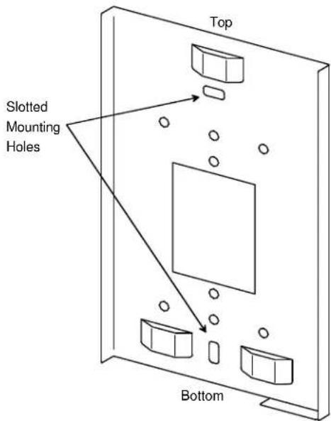
Figure 2. Mounting Bracket
- Using Figure 3 as a guide, mount the power supply onto the mounting bracket.
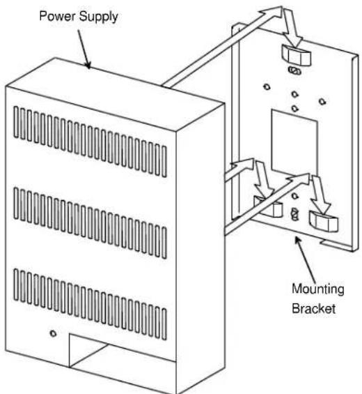
Figure 3. Mounting the Power Supply
Brand : Valcom
Model : VP-6124-UPS
Category : Battery charger