
Smart-UPS C 1500VA LCD 120V - Alimentation sans coupure APC - Free user manual and instructions
Find the device manual for free Smart-UPS C 1500VA LCD 120V APC in PDF.


| Type of Product | Uninterruptible Power Supply (UPS) |
| Model | Smart-UPS C 1500VA LCD 120V |
| Brand | APC |
| VA Rating | 1500 VA |
| Wattage | 900 W |
| Input Voltage | 120 V |
| Output Voltage | 120 V |
| Dimensions (H x W x D) | 10.3 x 17.1 x 17.5 inches (262 x 434 x 445 mm) |
| Weight | 48.7 lbs (22.1 kg) |
| Battery Type | Lead-acid, user-replaceable |
| Typical Battery Recharge Time | 6 hours |
| LCD Display | Yes, real-time status and diagnostics |
| Surge Protection | Yes, with surge energy rating |
| Automatic Voltage Regulation (AVR) | Yes, maintains output voltage within range |
| Number of Outlets | 8 (5 battery backup + 3 surge only) |
| Communication Ports | USB, Serial, SmartSlot for management card |
| Operating Temperature | 32°F to 104°F (0°C to 40°C) |
| Maintenance | Replace battery every 3-5 years; keep vents clean |
| Safety Features | Overload protection, short-circuit protection, battery shutdown |
| Repairability | User-replaceable battery; other repairs by qualified personnel |
Frequently Asked Questions - Smart-UPS C 1500VA LCD 120V APC
User questions about Smart-UPS C 1500VA LCD 120V APC
0 question about this device. Answer the ones you know or ask your own.
Ask a new question about this device
Download the instructions for your Alimentation sans coupure in PDF format for free! Find your manual Smart-UPS C 1500VA LCD 120V - APC and take your electronic device back in hand. On this page are published all the documents necessary for the use of your device. Smart-UPS C 1500VA LCD 120V by APC.
USER MANUAL Smart-UPS C 1500VA LCD 120V APC
Uninterruptible Power Supply
1000/1500 VA Tower
120 Vac
This manual is available in English on the enclosed CD.
The APC ^® by Schneider Electric Smart-UPS ^® 1000/1500 VA Tower is a high performance uninterruptible power supply (UPS). It provides protection for electronic equipment from utility power blackouts, brownouts, sags, and surges, small utility fluctuations and large disturbances. The UPS also provides battery backup power for connected equipment until utility power returns to safe levels or the batteries are fully discharged.
Safety and General Information
Read the Safety Guide included in the package before installing the UPS.
This unit is intended for indoor use only.
Do not operate this unit in direct sunlight, in contact with fluids, or where there is excessive dust or humidity.
Be sure the air vents on the UPS are not blocked. Allow adequate space for proper ventilation.
The battery typically lasts for two to five years. Environmental factors impact battery life. Elevated ambient temperatures, poor quality utility power, and frequent short duration discharges will shorten battery life.
Connect the Smart-UPS power cable directly to a wall outlet. Do not use surge protectors or extension cords.
The batteries are heavy. Remove the batteries prior to installing the UPS in a rack.
Specifications
For additional specifications, refer to the APC Web site at www.apc.com.
Environmental
| Temperature | Operating 0° to 40°C | (32° to 104°F) |
| Storage -15° to 45°C | (5° to 113°F)charge UPS battery every six months | |
| Maximum Elevation | Operating 3,000 m (10,000 ft) | |
| Storage 15,000 m (50,000 ft) | ||
| Humidity | 0% to 95% relative humidity, non-condensing | |
Product Overview
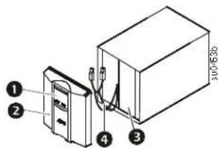
Front panel features
① Display interface
② Bezel
3 Battery
4 Internal battery connector
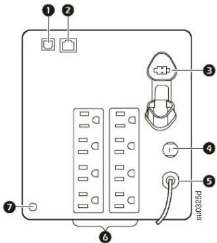
Rear panel features
USB Port
2 Serial data port
3 Battery connector
4 Circuit breaker
5 UPS input
6 Outlets
7 Ground screw
Installation
For UPS installation information, refer to the Smart-UPS Installation Guide 1000/1500 VA 120 Vac Tower, that is included with the UPS. The Quick Start guide is also available on the documentation CD included with the UPS and on the APC Web site, www.apc.com.
Operation
Connect Equipment to the UPS

Note: The UPS will charge to 90% capacity in the first three hours of normal operation. Do not expect full battery runtime capability during this initial charge period.
-
Connect equipment to the UPS.
-
Connect the UPS to the building utility power. Connect the UPS to a two-pole, three-wire, grounded source only.
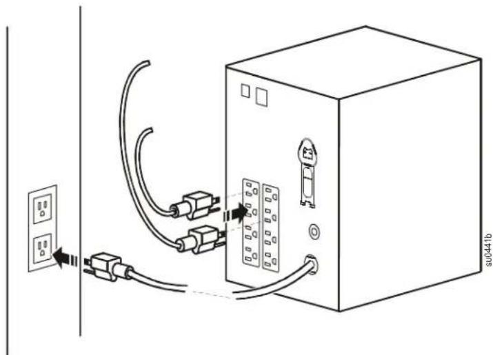

USB port: Connect to a computer to use power management software.

Serial port: Connect a serial port cable (not supplied) to use power management software.

Ground Screw: Connect the ground leads on transient voltage devices to the chassis ground screw(s), located on the rear panel of the UPS.
Power-Saving LCD Screen
The display interface can be configured to remain continuously illuminated or to extinguish after a period of inactivity to save electricity.
- Continuous Illumination mode: Press and hold the DISPLAY button for two seconds. The display will illuminate and the UPS will beep to confirm Continuous Illumination mode is activated.
- Power-Saving mode: Press and hold the DISPLAY button for two seconds. The display will extinguish and the UPS will beep to confirm Power-Saving mode is activated. While in Power-Saving mode, the display will illuminate if a button is pressed, it will extinguish after 60 seconds of inactivity.
Smart-UPS sensitivity settings
The Smart-UPS detects and reacts to line voltage distortions by transferring to battery power to protect connected equipment. In situations where either the UPS or the connected equipment is too sensitive for the input voltage level it is necessary to adjust the transfer voltage.
- Connect the UPS to a utility power source. Be sure the UPS is turned off.
- Press and hold the POWER button for six seconds. The load capacity bar will flash on and off, to indicate the UPS is in Program mode.
- Press the POWER button again to scroll through the menu options. The UPS will beep to confirm the selection.
Refer to the table for an explanation of the transfer voltage sensitivity levels.



Low sensitivity Medium sensitivity High sensitivity (Default) 97-136 Vac 103-130 Vac 106-127 Vac
Use this setting with equipment that is less sensitive to fluctuations in voltage or waveform distortions.
Use this setting under normal operating conditions.
Use this setting when connected equipment is sensitive to any minor fluctuations in voltage or waveform distortions.
Status Indicators
Front panel buttons and display
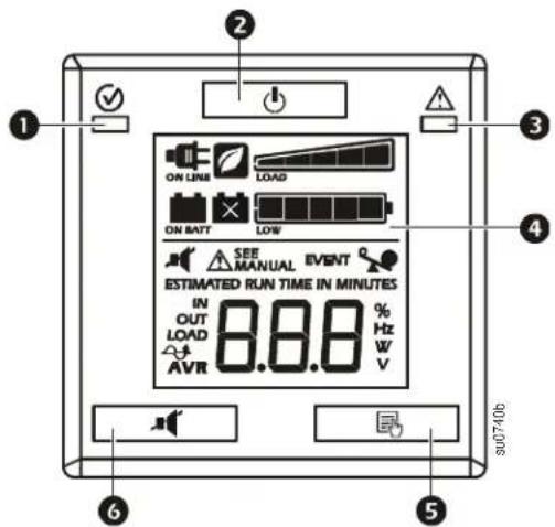
① Online/On Battery LED
2 POWER ON/OFF button
③ Site Wiring/System Fault LED
4 Display interface
5 DISPLAY button
6 MUTE button

Note: Refer to "Feature Quick-Reference" on page 7 for a detailed description of the front panel buttons.
 | On Line: The UPS is supplying conditioned utility power to connected equipment. |
 | Green mode: The UPS is operating at the most efficient level by bypassing unused AVR components while acceptable utility voltage is present. The UPS will enter and exit Green mode automatically and will not compromise power protection. |
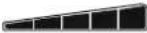 | Load Capacity: The load capacity percentage is indicated by the number of load bar sections illuminated. Each bar represents 20% of the load capacity. |
| ESTIMATED RUN TIME IN MINUTES | Estimated Run Time: This indicates the battery runtime minutes that remain if the UPS switches to battery power. |
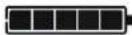 | Battery Charge: The battery charge level is indicated by the number of load bar sections illuminated. When all five blocks are illuminated, the battery is fully charged. Each bar represents 20% of the battery charge capacity. |
 | Overload: The equipment connected to the UPS is drawing more power than the voltage rating allows. |
 | Event: The event counter indicates the number of events that occurred to cause the UPS to switch to battery operation. |
 | Automatic Voltage Regulation (AVR): The UPS has an AVR boost feature that automatically regulates low levels of input voltage without using battery power. When illuminated, the UPS is compensating for low input voltage. |
 | In: Input voltage.Out: Output voltage. |
 | System Faults: An internal system fault has occurred. The fault number will illuminate on the display. Refer to “System Faults” on page 6. |
 | Mute: An illuminated line through the icon indicates that the audible alarm is disabled. |
 | Replace Battery: The battery is nearing the end of its service life. Replace the battery. |
 | On Battery: The UPS is supplying battery backup power to the connected equipment. |
LED status indicators
| Status LED Audible Indicator On | Audible Indicator Terminates | ||
| Power OnThe UPS is supplying utility power to connected equipment. | The Online LED illuminates green. | None N/A | |
| On BatteryThe UPS is supplying battery power from the internal battery pack. | The Online LED illuminates amber. | The UPS beeps 4 times every 30 seconds. | The beeping stops when utility power is restored or the MUTE button is pressed for 2 seconds. |
| System FaultThe UPS detects an internal system fault. | System Fault LED illuminates red. | Constant tone The alarm stops when the POWER ON/OFF button is pressed for 2 seconds to trigger a Fault Reset. | |
| Site Wiring FaultThe building wiring presents a shock hazard that must be corrected by a qualified electrical. | Site Wiring Fault LED flashes red. | None N/A | |
LCD status indicators
| Status LCD Icon Audible Alarms Audible | Alarm Terminates | ||
| On BatteryThe UPS is supplying battery power to the connected equipment. |  | Beeps 4 times every 30 seconds. | The beeping stops when utility power is restored or the UPS is turned off. |
| Utility Power OverloadAn overload condition has occurred while the UPS is operating on utility power. |  | Constant tone The alarm | stops when nonessential equipment is disconnected from the outlets or the UPS is turned off |
| Battery Power OverloadAn overload condition has occurred while the UPS is operating on battery power. |  | Constant tone The alarm | stops when nonessential equipment is disconnected from the outlets or the UPS is turned off. |
| Low BatteryThe UPS is supplying battery power to the connected equipment and the battery is near a total discharge state. | 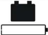 | Continuous beeping The | beeping stops when utility power is restored or the UPS is turned off. |
| Battery FaultThe UPS is operating on utility power, but the battery is not functioning properly. The battery has reached the end of its useful life. |  | N/A Replace the battery. | |
| System FaultThe UPS has experienced an internal fault. |  | N/A Identify the fault message on the display and refer to “System Faults”. | |
System Faults
The Smart-UPS will display a fault message in the event of an internal system fault.
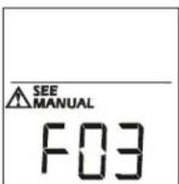
F01 Output Short Circuit
F02 Output Overload
F03 AVR Relay Weld
F04 Output Over Voltage
F05 Unit Over Temperature
F06 Inverter
Feature Quick-Reference
| Function Button | Timing(seconds) | UPSStatus | Description | |
| Power | ||||
| POWER ON | [228X] | 0.2 | Off | Press the POWER ON/OFF button to turn on the UPS and operate on utility power.If utility input power is not available the UPS will operate on battery power. |
| POWER OFF | [6850] | 2 | On | Press the POWER ON/OFF button to turn off the UPS. |
| Display | ||||
| Status Inquiry 0.2 On Vo [7680] the status or condition of the UPS. The LCD willilluminate for 60 seconds. | ||||
| Continuous Illumination/Power-Saving mode |  | 2 On The LCD | will illuminate and the UPS will beep to confirmContinuous Illuminationmode is activated.The LCD will extinguish and the UPS will beep to confirm thatPower-Savingmode is activated. While inPower-Savingmode,the LCD will illuminate if a button is pressed, then extinguish after 60 seconds of no activity. | |
| Mute | ||||
Event Specific 0.2 On D  le any audible alarms caused by an event. le any audible alarms caused by an event. | ||||
| General Status Enable/Disable | [0A45] | 2 On Enable or | disable the audible alarms. TheMuteicon willilluminate and the UPS will beep one time. TheMutefeature will not activate unless the UPS is operating on battery power. | |
| Sensitivity 6 Off The Lo Capacity icon will flash to indicate the UPS is inProgrammode. Use the POWER ON/OFF button to scroll through and select Low, Medium, and High sensitivity levels. The UPS will beep to confirm the selection. Refer to “Smart-UPS sensitivity settings” on page 4 for details. | ||||
| Self-Test | [2746] | 6 On The UPS | will run a test of the internal battery.Note: This will happen automatically when the UPS is turned ON. | |
| Event Reset | [85XX] | 0.2 | On | When theEventscreen is visible, press and hold DISPLAY, then press the POWER button to clear the utility failure event counter. |
| Fault Reset |  | 2 | Fault | After a fault has been identified, press the POWER ON/OFF button to remove the visual indication and return to standby status. |
Troubleshooting
Problem and Possible Cause Solution
| The UPS will not turn on or there is no output. | |
| The unit has not been turned on. Press the POWER button once to turn on the UPS. | |
| The UPS is not connected to utility power. | Be sure the power cable is securely connected to the unit and to the utility power supply. |
| The input circuit breaker has tripped. Reduce the load on the UPS. Disconnect nonessential equipment and reset the circuit breaker. | |
| The unit shows very low or no input utility voltage. | Check the utility power supply to the UPS by plugging in a table lamp. If the light is very dim, check the utility voltage. |
| The battery connector plug is not securely connected. | Be sure that all battery connections are secure. |
| There is an internal UPS fault. Do not attempt to use the UPS. Unplug the UPS and have it serviced immediately. | |
| The UPS is operating on battery, while connected to input utility power. | |
| The input circuit breaker has tripped. Reduce the load on the UPS. Disconnect nonessential equipment and reset the circuit breaker. | |
| There is very high, very low, or distorted input line voltage. | Move the UPS to a different outlet on a different circuit. Test the input voltage with the utility voltage display. If acceptable to the connected equipment, reduce the UPS sensitivity. |
| UPS is emitting an audible beeping sound. | |
| The UPS is operating normally. None. The UPS is protecting the connected equipment. | |
| UPS does not provide expected backup time. | |
| The UPS battery is weak due to a recent power outage or is near the end of its service life. | Charge the battery. Batteries require recharging after extended outages and wear out faster when put into service often or when operated at elevated temperatures. If the battery is near the end of its service life, consider replacing the battery even if the replace battery indicator has not illuminated. |
| The UPS is experiencing an overload condition. | Check the UPS load display. Unplug unnecessary equipment, such as printers. |
| The replace battery icon in the display interface is illuminated. | |
| The battery has a weak charge. Allow the battery to recharge for at least four hours. Then, perform a self-test. If the problem persists after recharging, replace the battery. | |
| The replacement battery is not properly connected. | Be sure that the battery connector is securely connected. |
| The System Fault LED is illuminated. | |
| Internal UPS fault. Do not attempt to use the UPS. Turn the UPS off and have it serviced immediately. | |
| The Site Wiring LED is flashing. | |
| Wiring faults detected include missing ground, hot-neutral, polarity reversal, and overloaded neutral circuit. | If the UPS indicates a site wiring fault, have a qualified electrician inspect the building wiring. |
Service
If the unit requires service, do not return it to the dealer. Follow these steps:
- Review the Troubleshooting section of the manual to eliminate common problems.
- If the problem persists, contact APC Customer Support through the APC Web site, www.apc.com.
a. Note the model number and serial number and the date of purchase. The model and serial numbers are located on the rear panel of the unit and are available through the LCD display on select models.
b. Call APC Customer Support and a technician will attempt to solve the problem over the phone. If this is not possible, the technician will issue a Returned Material Authorization Number (RMA#).
c. If the unit is under warranty, the repairs are free.
d. Service procedures and returns may vary internationally. Refer to the APC Web site for country specific instructions.
- Pack the unit properly to avoid damage in transit. Never use foam beads for packaging. Damage sustained in transit is not covered under warranty.
a. Always DISCONNECT THE UPS BATTERY before shipping in compliance with U.S. Department of Transportation (DOT) and IATA regulations. The battery may remain in the unit.
b. Internal batteries may remain connected in the XLBP during shipment, if applicable, not all units have XLBPs.
- Write the RMA# provided by Customer Support on the outside of the package.
- Return the unit by insured, pre-paid carrier to the address provided by Customer Support.
Transport the unit
- Shut down and disconnect all connected equipment.
- Disconnect the unit from utility power.
- Disconnect all internal and external batteries (if applicable).
- Follow the shipping instructions outlined in the Service section of this manual.
Two-Year Factory Warranty
This warranty applies only to the products you purchase for your use in accordance with this manual.
Terms of warranty
APC warrants its products to be free from defects in materials and workmanship for a period of two years from the date of purchase. APC will repair or replace defective products covered by this warranty. This warranty does not apply to equipment that has been damaged by accident, negligence or misapplication or has been altered or modified in any way. Repair or replacement of a defective product or part thereof does not extend the original warranty period. Any parts furnished under this warranty may be new or factory-remanufactured.
Non-transferable warranty
This warranty extends only to the original purchaser who must have properly registered the product. The product may be registered at the APC Web site, www.apc.com.
Exclusions
APC shall not be liable under the warranty if its testing and examination disclose that the alleged defect in the product does not exist or was caused by end user's or any third person's misuse, negligence, improper installation or testing. Further, APC shall not be liable under the warranty for unauthorized attempts to repair or modify wrong or inadequate electrical voltage or connection, inappropriate on-site operation conditions, corrosive atmosphere, repair, installation, exposure to the elements, Acts of God, fire, theft, or installation contrary to APC recommendations or specifications or in any event if the APC serial number has been altered, defaced, or removed, or any other cause beyond the range of the intended use.
THERE ARE NO WARRANTIES, EXPRESS OR IMPLIED, BY OPERATION OF LAW OR OTHERWISE, OF PRODUCTS SOLD, SERVICED OR FURNISHED UNDER THIS AGREEMENT OR IN CONNECTION HEREWITH. APC DISCLAIMS ALL IMPLIED WARRANTIES OF MERCHANTABILITY, SATISFACTION AND FITNESS FOR A PARTICULAR PURPOSE. APC EXPRESS WARRANTIES WILL NOT BE ENLARGED, DIMINISHED, OR AFFECTED BY AND NO OBLIGATION OR LIABILITY WILL ARISE OUT OF, APC RENDERING OF TECHNICAL OR OTHER ADVICE OR SERVICE IN CONNECTION WITH THE PRODUCTS. THE FOREGOING WARRANTIES AND REMEDIES ARE EXCLUSIVE AND IN LIEU OF ALL OTHER WARRANTIES AND REMEDIES. THE WARRANTIES SET FORTH ABOVE CONSTITUTE APC'S SOLE LIABILITY AND PURCHASER'S EXCLUSIVE REMEDY FOR ANY BREACH OF SUCH WARRANTIES. APC WARRANTIES EXTEND ONLY TO PURCHASER AND ARE NOT EXTENDED TO ANY THIRD PARTIES.
IN NO EVENT SHALL APC, ITS OFFICERS, DIRECTORS, AFFILIATES OR EMPLOYEES BE LIABLE FOR ANY FORM OF INDIRECT, SPECIAL, CONSEQUENTIAL OR PUNITIVE DAMAGES, ARISING OUT OF THE USE, SERVICE OR INSTALLATION, OF THE PRODUCTS, WHETHER SUCH DAMAGES ARISE IN CONTRACT OR TORT, IRRESPECTIVE OF FAULT, NEGLIGENCE OR STRICT LIABILITY OR WHETHER APC HAS BEEN ADVISED IN ADVANCE OF THE POSSIBILITY OF SUCH DAMAGES. SPECIFICALLY, APC IS NOT LIABLE FOR ANY COSTS, SUCH AS LOST PROFITS OR REVENUE, LOSS OF EQUIPMENT, LOSS OF USE OF EQUIPMENT, LOSS OF SOFTWARE, LOSS OF DATA, COSTS OF SUBSTITUENTS, CLAIMS BY THIRD PARTIES, OR OTHERWISE.
NO SALESMAN, EMPLOYEE OR AGENT OF APC IS AUTHORIZED TO ADD TO OR VARY THE TERMS OF THIS WARRANTY. WARRANTY TERMS MAY BE MODIFIED, IF AT ALL, ONLY IN WRITING SIGNED BY AN APC OFFICER AND LEGAL DEPARTMENT.
Warranty claims
Customers with warranty claims issues may access the APC customer support network through the Support page of the APC Web site, www.apc.com/support. Select your country from the country selection pull-down menu at the top of the Web page. Select the Support tab to obtain contact information for customer support in your region.
APC Worldwide Customer Support
Customer support for this or any other APC product is available at no charge in any of the following ways:
- Visit the APC Web site to access documents in the APC Knowledge Base and to submit customer support requests.
- www.apc.com (Corporate Headquarters)
Connect to localized APC Web sites for specific countries, each of which provides customer support information. - www.apc.com/support/
Global support searching APC Knowledge Base and using e-support. - Contact the APC Customer Support Center by telephone or e-mail.
- Local, country-specific centers: go to www.apc.com/support/contact for contact information.
For information on how to obtain local customer support, contact the APC representative or other distributors from whom you purchased your APC product.
- Uninterruptible Power Supply
- Safety and General Information
- Specifications
- Product Overview
- Front panel features
- Rear panel features
- Installation
- Operation
- Connect Equipment to the UPS
- Power-Saving LCD Screen
- Smart-UPS sensitivity settings
- Status Indicators
- System Faults
- Feature Quick-Reference
- Troubleshooting
- Service
- Transport the unit
- Two-Year Factory Warranty
- Terms of warranty
- Non-transferable warranty
- Exclusions
- Warranty claims
- APC Worldwide Customer Support
Brand : APC
Model : Smart-UPS C 1500VA LCD 120V
Category : Alimentation sans coupure