PowerScan PBT8300 - Barcode Reader DATALOGIC - Free user manual and instructions
Find the device manual for free PowerScan PBT8300 DATALOGIC in PDF.

| Type | Rugged handheld barcode scanner |
| Model | PowerScan PBT8300 |
| Brand | Datalogic |
| Dimensions (H x W x D) | 7.1 x 4.3 x 2.8 inches (180 x 109 x 71 mm) |
| Weight | 12.3 oz (350 g) |
| Power Supply | Rechargeable lithium-ion battery pack (3.7V, 2100 mAh) |
| Battery Life | Up to 50,000 scans per charge |
| Connectivity | Bluetooth 5.0, USB 2.0, RS232 serial |
| Scan Engine | 1D/2D imager with laser aimer (Class 2) |
| Scan Range | Up to 30 feet (9.1 m) for 100 mil barcodes |
| Drop Specification | 6.5 ft (2 m) to concrete |
| IP Rating | IP65 (dust and water resistant) |
| Operating Temperature | -20°C to 50°C (-4°F to 122°F) |
| Functions | Read 1D/2D barcodes, PDF417, QR codes, Data Matrix, postal codes |
| Maintenance & Cleaning | Clean with a soft cloth dampened with mild detergent; avoid abrasive cleaners |
| Safety | Class 2 laser product; avoid direct eye exposure |
| Spare Parts | Replacement battery, USB cable, hard rubber holster, scan window cover |
| Repairability | Field-replaceable battery and scan window; service center for internal components |
| Warranty | 2 years limited warranty |
| Compliance | FCC, CE, RoHS |
Frequently Asked Questions - PowerScan PBT8300 DATALOGIC
User questions about PowerScan PBT8300 DATALOGIC
0 question about this device. Answer the ones you know or ask your own.
Ask a new question about this device
Download the instructions for your Barcode Reader in PDF format for free! Find your manual PowerScan PBT8300 - DATALOGIC and take your electronic device back in hand. On this page are published all the documents necessary for the use of your device. PowerScan PBT8300 by DATALOGIC.
USER MANUAL PowerScan PBT8300 DATALOGIC
PowerScan® BT8300 Family
Industrial Handheld Bar Code Reader with Bluetooth® Wireless Technology
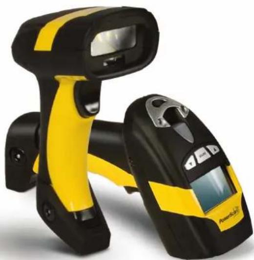
natural_image
Product photo of a yellow and black barcode scanner with a digital display (no visible text or symbols)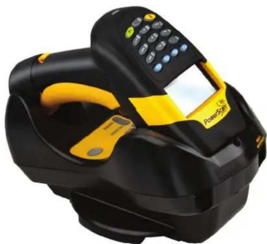
natural_image
Black and yellow portable medical device with a digital display and control panel (no visible text or symbols)Product Reference Guide
Datalogic Scanning, Inc.
959 Terry Street
Eugene, Oregon 97402
USA
Telephone: (541) 683-5700
Fax: (541) 345-7140
An Unpublished Work - All rights reserved. No part of the contents of this documentation or the procedures described therein may be reproduced or transmitted in any form or by any means without prior written permission of Datalogic Scanning, Inc. or its subsidiaries or affiliates ("Datalogic" or "Datalogic Scanning"). Owners of Datalogic products are hereby granted a non-exclusive, revocable license to reproduce and transmit this documentation for the purchaser's own internal business purposes. Purchaser shall not remove or alter any proprietary notices, including copyright notices, contained in this documentation and shall ensure that all notices appear on any reproductions of the documentation.
Should future revisions of this manual be published, you can acquire printed versions by contacting your Datalogic representative. Electronic versions may either be downloadable from the Datalogic website (www.scanning.datalogic.com) or provided on appropriate media. If you visit our website and would like to make comments or suggestions about this or other Datalogic publications, please let us know via the "Contact Datalogic" page.
Disclaimer
Datalogic has taken reasonable measures to provide information in this manual that is complete and accurate, however, Datalogic reserves the right to change any specification at any time without prior notice.
Datalogic and the Datalogic logo are registered trademarks of Datalogic S.p.A. in many countries, including the U.S.A and the E.U. All other brand and product names referred to herein may be trademarks of their respective owners.
Microsoft Windows ^® , Windows ^® XP and the Windows logo are registered trademarks of Microsoft Corporation.
Patents
This product is covered by one or more of the following patents.
Design Pat. AU 310201; AU 310202; CN 693980; CN735959; HK 0602013.5M001; HK 0602013.5M002; JP 1305693; KR 30-0460940; US D570,843 S; USD588,596 S.
US Pat. 5,992,740; 6,305,606 B1; 6,412,698 B2; 6,517,003; 6,808,114 B1; 6,997,385 B2; 7,387,246 B2; 5,367,151; 5,449,893; 5,545,889; 6,098,877; 6,220,514 B1; 6,412,698 B2; 6,607,132 B1; 6,817,529 B2; 6,834,805 B2.
European Pat. 789,315 B1; 895,175 B1; 1,128,314 B1; 1,128,315 B1; 1,396,811 B1; 1,413,971 B1; 1,816,585 B1; 1,942,442 B1.
Additional patents pending.
CONTENTS
1 INTRODUCTION....1
2 INSTALLATION....1
2.1 BC 8030-BT Interface Cable Connections ....1
2.2 RS-232 Connection....2
2.3 USB....2
2.4 IBM USB POS....2
2.5 WEDGE Connection 2
2.6 PEN Emulation Connection....2
2.7 PowerScan BT8300 Battery Maintenance....3
2.7.1 Battery Safety 3
2.7.2 Battery Charging....4
2.7.3 Replacing PowerScan ^ BT8300 Batteries 4
2.8 Mounting The BC 8030-BT Cradle 5
2.8.1 Desktop Mounting....6
2.8.2 Wall Mounting....8
3 POWERSCAN ^® BT8300 SYSTEM....10
3.1 POWERSCAN™ BT8300/BC 8030-BT 10
3.2 POWERSCAN™ BT8300/BLUETOOTH-ENABLED PC 10
4 CONFIGURATION....11
4.1 Configuration Methods....11
4.1.1 Reading Configuration Barcodes....11
4.1.2 Using Datalogic Aladdin™ 11
4.1.3 Copy Command....11
4.1.4 Sending Configuration Strings from Host....11
4.2 Setup Procedures 11
4.2.1 Restore PowerScan BT 8300 Default....11
4.3 Connecting the PowerScan BT8300....12
4.3.1 Overview 12
PowerScan™ BT8300/BC 8030-BT Configuration....12
PowerScan™ BT8300/Bluetooth-Enabled PC Configuration 12
4.3.2 Before You Begin 12
4.4 Interface Selection 19
4.5 USB Reader Configuration....21
4.6 Changing Default Settings....22
RS-232 PARAMETERS 23
USB PARAMETERS 26
WEDGE PARAMETERS....31
PEN EMULATION 36
DATA FORMAT 41
POWER SAVE 55
READING PARAMETERS ....57
DECODING PARAMETERS 62
CODE SELECTION....65
ADVANCED FORMATTING....79
RADIO PARAMETERS 95
BLUETOOTH PARAMETERS....98
DISPLAY and KEYPAD PARAMETERS (3-Key Model)....108
DISPLAY and KEYPAD PARAMETERS (16-Key Model)....112
5 REFERENCES....127
5.1 RS-232 Parameters 127
5.1.1 Handshaking....127
5.2 Pen Parameters....128
5.2.1 Minimum Output Pulse 128
5.2.2 Conversion to Code 39 and Code 128....128
5.2.3 Overflow 128
5.2.4 Output and Idle Levels....129
5.2.5 Inter-Block Delay 129
5.3 Data Format....130
5.3.1 Header/Terminator Selection....130
5.3.2 Define Special Key Sequence 131
5.3.3 Address Stamping 137
5.3.4 Address Delimiter 137
5.3.5 Time Stamping Format....137
5.3.6 Time Stamping Delimiter 137
5.4 Power Save....138
5.4.1 Sleep State....138
5.4.2 Enter Sleep Timeout....138
5.5 Reading Parameters 138
5.5.1 Trigger Signal 138
5.5.2 Trigger Click 138
5.5.3 Trigger-Off Timeout 138
5.5.4 Reads per Cycle 138
5.5.5 Safety Time 139
5.6 Decoding Parameters....139
5.6.1 Ink-Spread 139
5.6.2 Overflow Control....139
5.6.3 Interdigit Control 139
5.7 Advanced Formatting....139
5.7.1 Match Conditions....139
5.8 Radio Parameters 140
5.8.1 Power-Off Timeout....140
5.8.2 Beeper Control for Radio Response....140
5.8.3 Batch Mode 140
5.8.4 See Me 141
5.9 BLUETOOTH PARAMETERS....142
5.9.1 Communication Type....142
5.9.2 Link By Contact....142
5.9.3 Link By Label 142
5.9.4 Start Up Connect....143
5.9.5 Auto Reconnect....143
5.9.6 Reconnect Attempt Interval 143
5.9.7 Reconnect Attempt Mode 143
5.9.8 Power Class 143
5.9.9 Security Mode....144
5.9.10 PIN Code & PIN Length....144
5.9.11 Variable PIN Code....144
5.9.12 HID Caps Lock Auto-Recognition (IBM AT-Compatible Only) 144
5.9.13 HID Alt Mode 144
5.9.14 HID Interchar Delay 145
5.9.15 HID Send Unknown ASCII Character 145
5.10 Display Parameters (Some BT8300 Models only)....145
5.10.1 Display Mode....145
5.11 Configuration Editing Commands....146
5.12 Custom Default Configuration....146
5.13 Code Type Recognition....147
5.14 Configuration Copying Commands 147
5.14.1 Copy PowerScan™ BT8300 Series 147
5.14.2 Copy BC 8030-BT....148
5.15 Default Parameters for POS Terminals....149
5.16 Firmware Upgrade 150
5.17 16-Key PowerScan BT8300-DK Display and Keypad Parameters....150
5.17.1 16-key Keyboard Data Format Enable/Disable....150
5.17.2 Scanner Code ID 151
5.17.3 Scanner Code Length....151
6 MESSAGE FORMATTING 152
6.1 Standard Message Formatting....152
6.2 Advanced Message Formatting....152
6.3 Messages from SCANNER Command Keys....153
6.3.1 PowerScan BT8300 keypad 153
7 TECHNICAL FEATURES ....155
7.1 PowerScan ^® BT8300....155
7.2 BC 8030-BT 156
7.3 System CONFIGURATION....157
7.4 Status Indicators 157
7.5 Reading Diagrams 159
GENERAL VIEW
POWERSCAN® BT8300 READERS
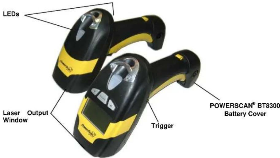
Figure A – PowerScan® BT8300 Series Readers
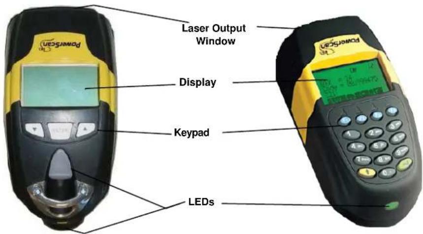
Figure B – PowerScan® BT8300 Series Readers with Display
BC 8030-BT CRADLE
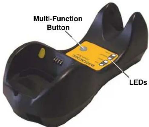
Figure C - BC 8030-BT
The label on the cradle contains LED indicators and a multi-function button. When the button is pressed for less than 8 seconds, the cradle will act in one of two ways:
- If not already paired with a BT8300, it will start to search for all "discoverable" BT8300 scanners in radio range; this procedure allows a link with a maximum of four PowerScan BT8300 readers
OR
- If it already has a connection with at least one PowerScan BT8300 reader, it will transmit a "broadcast" message." When the broadcast is sent, all properly configured scanners that are linked to that base and within radio range coverage will emit a beep and blink within 5 seconds.
This functionality is useful to:
- verify which scanners are linked to a certain base station
- detect a scanner forgotten somewhere
When the button is pressed for longer than 8 seconds, all paired scanners will be unpaired.
1 INTRODUCTION
Datalogic renews its range of industrial laser scanners introducing the PowerScan® BT8300 family. Robustness and ergonomics remain unsurpassed: clearly audible beeper and bright "good read" LEDs for areas where noise levels are normally high; the aim mode, which helps point to the right code, has now been extended to the whole PowerScan® family. Optical parts are completely suspended on shock absorbers and a careful choice of the body materials, such as the co-moulded rubber, protect the PowerScan® from damage due to "falls".
New enhanced architecture, based on an M16 high-speed microprocessor, enables exceptional performance for promptness and reading speed of standard codes as well as the ability to read poorly printed and damaged codes. Puzzle Solver Technology™, a patent from Datalogic, adds further strength to the PowerScan® powerful engine.
In all applications where mobility is a value, the new PowerScan® BT8300 represents the key to increase productivity and flexibility in the working area. PowerScan® BT8300 communicates through a low power, license free radio in the 2.4 GHz band (Bluetooth®) and allows bi-directional communication between the base station and the host. PowerScan® BT8300 also includes a display and either a 3 or 16-key push-button keypad. Thanks to these features, the operator can type unreadable codes or additional information (like quantity) and visualize the code read. The cordless system offers scalable solutions to solve simple applications and complex projects:
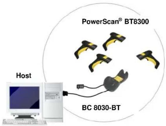
• PowerScan BT8300/BC 8030-BT: up to four readers can transmit data to one base station
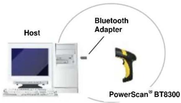
• PowerScan BT8300/Bluetooth-Enabled PC: up to 7 readers can connect with the Host.
Your PowerScan ^® reader is supplied with its own Quick Reference Guide, which provides connection, diagrams, reading diagrams, basic application parameter settings, default values, and specific technical features. You can use either the Quick Reference Guide or this Manual for initial configuration in order to set the default values and select the interface for your application. This manual provides all the necessary information for complete mechanical installation and system software configuration.
2 INSTALLATION
2.1 BC 8030-BT Interface Cable Connections
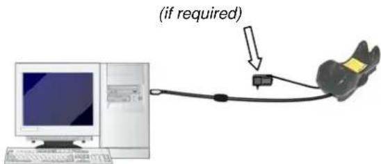
The BC 8030-BT incorporates a multi-standard interface, which can be connected to a Host by simply plugging the correct interface cable into the Host connector, placed on the base of the cradle. In addition the cradle must be connected to an external power supply.
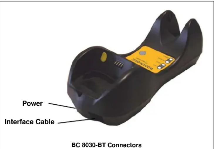
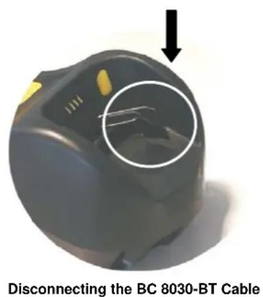
To disconnect the cable, insert a paper clip or other similar object into the hole corresponding to the Host connector on the body of the cradle. Push down on the clip while unplugging the cable.
2.2 RS-232 Connection
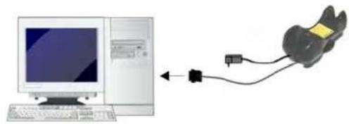
natural_image
Diagram showing a desktop computer connected to a mouse via cable (no text or symbols present)2.3 USB
2.4 IBM USB POS
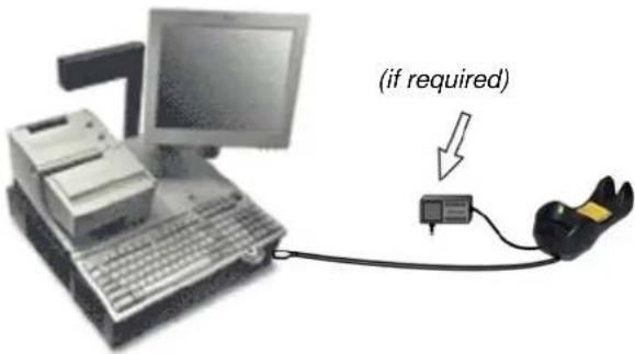
2.5 WEDGE Connection
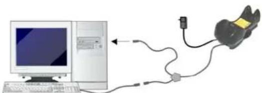
natural_image
Diagram showing a computer connected to a device via cable and power line (no text or symbols present)2.6 PEN Emulation Connection
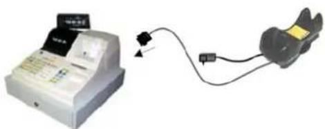
natural_image
Illustration of a white cash register with a digital display and connected to a black cable (no text or symbols visible)2.7 PowerScan ^® BT8300 Battery Maintenance

NOTE
Before installing the Battery, read "Battery Safety" on this and the following pages. Datalogic recommends annual replacement of rechargeable battery packs to ensure maximum performance.
2.7.1 Battery Safety

WARNING
Do not discharge the battery using any device except the scanner. When the battery is used in devices other than the designated product, it may damage the battery or reduce its life expectancy. If the device causes an abnormal current to flow, it may cause the battery to become hot, explode or ignite and cause serious injury.
Lithium-ion battery packs may get hot, explode or ignite and cause serious injury if exposed to abusive conditions. Be sure to follow the safety warnings listed below:

WARNING
Do not place the battery pack in fire or heat.
Do not connect the positive terminal and negative terminal of the battery pack to each other with any metal object (such as wire).
Do not carry or store the battery pack together with metal objects.
Do not pierce the battery pack with nails, strike it with a hammer, step on it or otherwise subject it to strong impacts or shocks.
Do not solder directly onto the battery pack.
Do not expose the battery pack to liquids, or allow the battery to get wet.
Do not apply voltages to the battery pack contacts.
In the event the battery pack leaks and the fluid gets into your eye, do not rub the eye. Rinse well with water and immediately seek medical care. If left untreated, the battery fluid could cause damage to the eye.

CAUTION
Always charge the battery at 32^-104^ ( 0^-40^ ) temperature range. Use only the authorized power supplies, battery pack, chargers, and docks supplied by your Datalogic reseller. The use of any other power supplies can damage the device and void your warranty. Do not disassemble or modify the battery. The battery contains safety and protection devices, which, if damaged, may cause the battery to generate heat, explode or ignite. Do not place the battery in or near fire, on stoves or other high temperature locations. Do not place the battery in direct sunlight, or use or store the battery inside cars in hot weather. Doing so may cause the battery to generate heat, explode or ignite. Using the battery in this manner may also result in a loss of performance and a shortened life expectancy. Do not place the battery in microwave ovens, high-pressure containers or on induction cookware. Immediately discontinue use of the battery if, while using, charging or storing the battery, the battery emits an unusual smell, feels hot, changes color or shape, or appears abnormal in any other way. Do not replace the battery pack when the device is turned on. Do not remove or damage the battery pack's label. Do not use the battery pack if it is damaged in any part. Battery pack usage by children should be supervised.
As with other types of batteries, Lithium-Ion (LI) batteries will lose capacity over time. Capacity deterioration is noticeable after one year of service whether the battery is in use or not. It is difficult to precisely predict the finite life of a LI battery, but cell manufacturers rate them at 500 charge cycles. In other words, the batteries should be expected to take 500 full discharge / charge cycles before needing replacement. This number is higher if partial discharging / recharging is adhered to rather than full / deep discharging,
The typical manufacturer advertised useful life of LI batteries is one to three years, depending on usage and number of charges, etc., after which they should be removed from service, especially in mission critical applications. Do not continue to use a battery that is showing excessive loss of capacity, it should be properly recycled / disposed of and replaced. For most applications, batteries should be replaced after one year of service to maintain customer satisfaction and minimize safety concerns.
Collect and recycle waste batteries separately from the device in compliance with European Directive 2006/66/EC, 2002/95/EC, 2002/96/EC and subsequent modifications, US and China regulatory and others laws and regulations about the environment.
2.7.2 Battery Charging
Once the system is connected and powered, place the PowerScan® BT8300 into the cradle to charge the battery. When the reader is correctly inserted in the cradle, the "Reader" red LED on the cradle goes on to indicate that the battery is charging. The "Reader" green LED on the cradle goes on when the battery is completely charged.
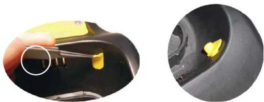
2.7.3 Replacing PowerScan ^® BT8300 Batteries
To change the batteries in your PowerScan® BT8300 scanner, press the black button or unscrew the fixing screw on the handle cover and extract the battery pack from the reader handle.

natural_image
Close-up of hands holding a handheld device with yellow and black buttons, no visible text or symbols
natural_image
Close-up of hands using a handheld device to adjust a black-and-yellow tool, with a numbered callout (2) indicating the step.
NOTE
When the batteries are extracted from the scanner, the timer maintains the current hour and date for about 1 minute.
Replace the old battery pack with a new one by inserting it within the reader handle and pushing it until it clicks.

WARNING
Do not incinerate, disassemble, short terminals or expose to high temperature. Risk of fire, explosion. Use specified charger only. Risk of explosion if the battery is replaced by an incorrect type. Dispose of the batteries as required by the relevant laws in force. See "Battery Safety" on the previous pages.
2.8 Mounting The BC 8030-BT Cradle
The cradle package contains the following items:
- BC 8030-BT Cradle
• BC 8030-BT Quick Reference Guide
- 2 adhesive strips
• 2 wall-mounting lock hinges
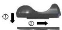
- 1 horizontal base
- 1 inclined base
The cradle (BC 8030-BT) can be mounted for portable or fixed desktop usage, or it can be fixed to a wall. The horizontal base allows portable and fixed desktop usage, while the inclined base provides desktop and wall mounting guaranteeing a comfortable handling of the PowerScan® BT8300 reader.

natural_image
Black and yellow object resembling a stylized shoe or cushion (no text or symbols visible)BC 8030-BT Cradle mounted on the Horizontal Base

natural_image
Black plastic cushion or seat with a curved top and side placket (no text or symbols visible)
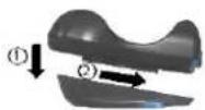
natural_image
Black and yellow abstract object resembling a stylized shoe or cushion (no text or symbols visible)BC 8030-BT Cradle mounted on the Inclined Base
2.8.1 Desktop Mounting
For desktop usage, you can mount the cradle either on the horizontal base, for reduced overall dimensions, or on the inclined base for a more ergonomic taking out and insertion of the reader onto the cradle.
Horizontal base
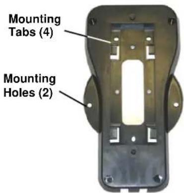
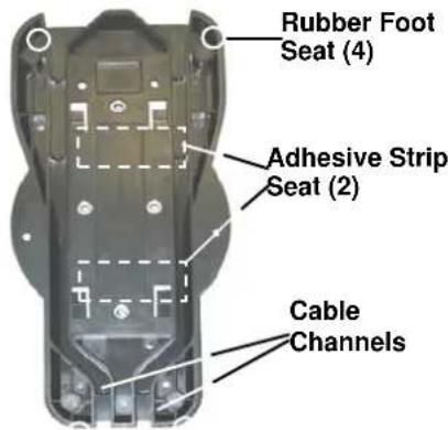
Top View Bottom View
Top View
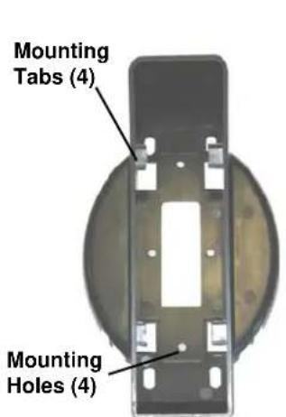
Inclined base
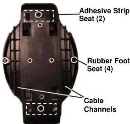
Bottom View
Portable Desktop Use
- Correctly position the BC 8030-BT onto the base by sliding it along the mounting tabs until aligned.
- Carefully clean the rubber foot seats of the base to remove any impurities that could reduce adhesion.
- Remove the protective plastic from the rubber feet and stick them onto the bottom surface of the base.
- If mounting the BC 8030-BT cradle, insert the antenna in the appropriate hole on the body of the cradle and screw it clockwise until tight.
Fixed Desktop Use
For fixed desktop installation, use the adhesive strips or fixing screws (not provided) according to your needs.
For mounting with adhesive strips:
- Position the cradle onto the base by sliding it along the mounting tabs until aligned.
- Carefully clean the adhesive strip seats of the base to remove any impurities that could reduce adhesion.
-
Remove the protective plastic from one side of the adhesive strips and stick them onto the base surface.
-
Position the cables to be connected to the BC 8030-BT cradle along the dedicated channels, as shown in the figures below:
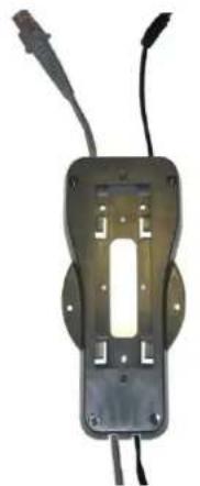
natural_image
Electronic component with two leads and a central slot, shown without any text or symbolsHorizontal Base
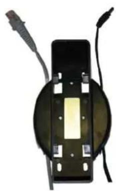
natural_image
Close-up of a black electronic component with a yellow central slot and two wires attached (no visible text or symbols)Inclined Base
- Remove the plastic from the other side of the strips and affix the base to the table.
- If mounting the BC 8030-BT cradle, insert the antenna in the appropriate hole on the body of the cradle and screw it clockwise until tight.
For mounting with screws:
- Position the cables to be connected to the BC 8030-BT cradle along the dedicated channels, as shown in the figures below:
- Position the base on the table and affix it by means of the screws (not provided).
- Position the cradle on the base by sliding it along the mounting tabs until aligned.
- If mounting the BC 8030-BT cradle, insert the antenna in the appropriate hole on the body of the cradle and screw it clockwise until tight.
2.8.2 Wall Mounting

natural_image
Black and yellow abstract object resembling a stylized shoe or cushion (no text or symbols visible)Remove the yellow caps and insert the two wall mounting lock hinges provided with your cradle.
natural_image
Close-up of a hand holding a yellow plastic clip next to a black mechanical component, with a close-up inset showing the interior area (no text or symbols visible)- Position the cables to be connected to the BC 8030-BT cradle along the dedicated channels (see figures on page 7).
If using the adhesive strips:
a. Carefully clean the adhesive strip seats of the base to remove any impurities that could reduce adhesion.
b. Remove the protective plastic from one side of the adhesive strips and stick them onto the base surface.
c. Remov e the plastic from the other side of the strips and affix the base to the wall as indicated in the figure below.
If using the mounting screws:
a. Using the mounting holes on the base as a pattern, mark the wall where you desire to mount the BC 8030-BT.
b. Dril I the appropriate size holes and insert the threaded dowels (not provided) into the holes.
c. Position the base on the wall as indicated in the figure below and affix it by means of the screws (not provided).

natural_image
Black plastic object with curved edge and small protrusions (no visible text or symbols)Inclined Base Wall-mounting
- Attach the cradle on the base by sliding it along the mounting tabs until aligned.
- If mounting the BC 8030-BT cradle, insert the antenna in the appropriate hole on the body of the cradle and screw it clockwise until tight.
3 POWERSCAN ^® BT8300 SYSTEM
There are two basic system layouts that can be employed:
• PowerScan BT8300/BC 8030-BT
• PowerScan BT8300/Bluetooth-Enabled PC
3.1 POWERSCAN™ BT8300/BC 8030-BT
3.2 POWERSCAN™ BT8300/BLUETOOTH-ENABLED PC
4 CONFIGURATION
4.1 Configuration Methods
4.1.1 Reading Configuration Barcodes
This manual can be used for complete setup and configuration of your reader by following the setup procedures in this chapter (see par. 4.2 for an overview).
If you wish to change the default settings, this manual provides complete configuration of your reader in an easy way.
To configure your reader:
- Open the folded page in Appendix C with the hex-numeric table and keep it open during the device configuration.
- Read the Enter Configuration code ONCE, available at the top of each page of configuration.
- Modify the desired parameters in one or more sections following the procedures given for each group.
- Read the Exit and Save Configuration code ONCE, available at the top of each page of configuration.
Reference notes describing the operation of the more complex parameters are given in chapter 1.
4.1.2 Using Datalogic Aladdin™
Datalogic Aladdin™ is a multi-platform utility program providing a quick and user-friendly configuration method via the RS-232/USB-COM interface.
It also allows upgrading the software of the connected device (see the Datalogic Aladdin™ Help On-Line for more details).
4.1.3 Copy Command
A previously configured device (Master), can be used to send its configuration directly to other devices of the same type (Slaves). The particular procedure for each device is given in par. 5.14.
4.1.4 Sending Configuration Strings from Host
An alternative configuration method is provided in Appendix A using the RS-232 interface. This method is particularly useful when many devices need to be configured with the same settings. Batch files containing the desired parameter settings can be prepared to configure devices quickly and easily.
4.2 Setup Procedures
4.2.1 Restore PowerScan BT 8300 Default
Before starting configuration and every time you want to restore factory settings, read the label below. Please note that the default mode on PowerScan BT8300 is Handheld - Cradle communication:
Restore PowerScan BT8300 Default

4.3 Connecting the PowerScan BT8300
4.3.1 Overview
PowerScan™ BT8300/BC 8030-BT Configuration
- Connect a BC 8030-BT cradle to the Host. For installation and connection information see the BC 8030-BT Quick Reference Guide.
- Charge the PowerScan BT8300 battery using a BC 8030-BT, the CHR-PM80 or BC-P080 chargers as described in the BT8300 Quick Reference Guide. A full charge takes 4 hours if using an external power supply; while it takes up to 10 hours if supplying power through the USB port.
- Configure the reader as described in this manual or the BT8300 Quick Reference Guide.
- Configure the BC 8030-BT cradle. See BC 8030-BT Configuration in the BC 8030-BT Quick Reference Guide.
- OR -
PowerScan™ BT8300/Bluetooth-Enabled PC Configuration
- Install any drivers provided with the Bluetooth adapter.
- Charge the PowerScan™ BT8300 battery using a BC-8030-BT, the CHR-PM80 or the MC-P080 chargers as described in this Quick Reference Guide. A full charge takes 4 hours if using an external power supply; while it takes up to 10 hours if supplying power through the USB port.
- Configure the reader as described in this manual or the BT8300 Quick Reference Guide.
4.3.2 Before You Begin
In order to use the connection procedures below, the handheld and base station must be in an UNPAIRED state. If the reader is connected to a device, you must follow the procedure below to UNPAIR the Base Station and the handheld before attempting to link to a new device. If the handheld is not already connected to another device, then you can skip this step and go straight to the Linking instructions that begin on the next page.
Unpairing the Reader
To unpair the PowerScan BT8300 reader from a BC 8030-BT base station, press and hold the button on the BC 8030-BT (>8 seconds), then read the Unpair bar code below with each PowerScan BT8300 which you want to unpair from the cradle.
Unpair

You can Unpair the PowerScan BT8300 reader from a Bluetooth-Enabled PC to make it available for pairing with another PC. Read the bar code above to disconnect the reader from its PC.
Please note that in order to connect different scanners to a Base that is already connected to the maximum four scanners, you must follow the procedure above.
Linking the PowerScan™ BT8300 to the BC 8030-BT Cradle
The PowerScan BT 8300 reader can be connected with the PowerScan BC 8030-BT cradle in either of three ways. After the BC-8030-BT cradle is powered on and connected to the Host, configure the Power Scan BT8300 by reading the following bar codes in the given sequence as described in each section.

Remember: The mandatory condition for establishing a new connection between a BT reader and a BT cradle is that they share the same security configuration. The connection timeout is 30 seconds. Four ascending beeps from the reader indicate a successful link, otherwise there are four descending tones.
Link by Contact
Read the bar codes in sequence as shown in the steps below:
1.
Enter Configuration

2.
Handheld - Cradle

3.
Link by Contact

4.
Exit and Save Configuration

- Firmly position the reader onto the cradle. The BC 8030-BT cradle will emit a beep and the yellow LED will blink while the cradle is trying to establish the connection. Four ascending beeps will be emitted, signaling that the BC 8030-BT cradle has been successfully connected to the PowerScan BT8300, and the yellow LED on the cradle will stop blinking.
- To connect another PowerScan PBT8300 to the BC 8030-BT cradle, repeat the sequence from steps 1 through 5. One Cradle can connect with a maximum of four readers.
- Upon completing the connection between the reader and cradle you must set up the correct interface for your system. Refer to the BC 8030-BT Base Station Charger QRG for information and programming labels, and scan the appropriate bar code to select your system's interface type.
END of procedure. YOUR READER IS NOW READY TO READ CODES.
Link by Inquiry
1.
Enter Configuration

2.

3.
Exit and Save Configuration

- To connect another PowerScan PBT8300 to the BC 8030-BT cradle, repeat in the sequence from steps 1 through 3 before continuing. One Cradle can connect with a maximum of four readers.
- Quickly press the button (<8 seconds and release) on the BC 8030-BT cradle. The yellow LED on the cradle will blink and it will search for any PowerScan BT 8300 readers in radio range. After finishing, the cradle will emit a beep and begin to link with PowerScan BT8300 readers found.
- The green LED on each PowerScan BT8300 reader will blink when the BC 8030-BT cradle tries to link with it. To confirm the connection with the cradle, press the trigger on the reader within 10 seconds, before the timeout expires.
- Four ascending beeps will be emitted, signaling that the BC 8030-BT cradle has been successfully connected to the PowerScan BT8300, and the green LED on the reader will stop blinking.
- Upon completing the connection between the reader and cradle you must set up the correct interface for your system. Refer to the BC 8030-BT Base Station Charger QRG for information and programming labels, and scan the appropriate bar code to select your system's interface type.
END of procedure. YOUR READER IS NOW READY TO READ CODES.
Link by Label
1.
Enter Configuration

2.

3.

4.
Read 12 characters to represent Cradle Bluetooth Address
5.
Exit and Save Configuration

- Four ascending beeps will be emitted, signaling that the PowerScan BT8300 has been successfully connected to the BC 8030-BT Cradle and the Green LED
END of procedure. YOUR READER IS NOW READY TO READ CODES.

NOTE
Another way to link the PowerScan™ BT8300 to the BC 8030BT Cradle with the Link by Label method can be to create a label that includes the appropriate command and the cradle MAC address. Please refer to the Bluetooth Parameters Reference in this Product Reference Guide (PRG), o contact Technical Support for more information.
Linking the PowerScan BT8300 to a Bluetooth-Enabled PC
The PowerScan BT8300 reader can optionally be linked to a Bluetooth-enabled host with the serial port profile (SPP) or human interface device (HID) as a virtual keyboard.

NOTE
Depending on the driver used by your device, specific actions may be required the first time a connection is made between the PowerScan PBT8300 and a generic Bluetooth peripheral. For further information, download "Initial Bluetooth Connection Guide," available on the Datalogic website in the PowerScan BT section.
Linking to a PC in Serial Port Profile (Slave) Mode
To link a PowerScan BT8300 reader in Serial Port Profile (Slave) Mode to a Bluetooth-enabled host, read the following codes in the given sequence.
Enter Configuration

1.
Serial Port Profile (Slave)

2.
Exit and Save Configuration
3.

- Use the HOST computer's Bluetooth manager to "Add Bluetooth Device Wizard" and select "PowerScan BT8300." When prompted for a passkey, enter the default of "1234" or whatever you have already assigned to your scanner. A window will notify you of Incoming Port and Outcoming Port when the PowerScan BT8300 is successful added to the PC.
- Open the Outcoming Port using your application program; for test purposes you can verify the communication using the Hyperterminal tool in Windows.
- Four ascending beeps will be emitted, signaling that the PowerScan BT8300 has been successfully connected to the Bluetooth-enabled PC.
END of procedure. YOUR READER IS NOW READY TO READ CODES.
Linking to a PC in Serial Port Profile (Master) Mode
To link a PowerScan BT8300 reader in Serial Port Profile (Master) Mode to a Bluetooth-enabled host, follow the instructions below and read the bar codes in the given sequence.
- Select the "COM Ports" tab on the Window's Bluetooth Manager and add the Incoming Port. You will receive a notification that the Incoming Port is added successfully.
- Open the Incoming Port using your application program; for test purposes you can verify the communication using the Hyperterminal tool in Windows.
Enter Configuration

3.
Serial Port Profile (Master)

4.

5.
6.
7.
12 digits for the Host Bluetooth adapter
Exit and Save Configuration

-
When prompted for a passkey, enter the default of "1234" or whatever you have already assigned to your scanner.
-
Four ascending beeps will be emitted, signaling that the PowerScan BT8300 has been successfully connected to the Bluetooth-enabled PC and the Green LED on the reader will stop blinking.
END of procedure. YOUR READER IS NOW READY TO READ CODES.
Linking to a PC in HID
To link a PowerScan BT8300 reader in HID to a Bluetooth-enabled PC, please read the following bar codes in the given sequence:
1.
Enter Configuration

2.

3.
Exit and Save Configuration

- Use the host computer's Bluetooth Manager to "Add Bluetooth Device Wizard" and select "PowerScan BT8300." In the next window, enter the PIN code if you are using Security Mode 2 or Security Mode 3, or choose "Don't use passkey" if you set Security Mode 1.

NOTE
The default Security Mode in HID mode is mode 1 - Authentication and Encryption Disable.
- Four ascending beeps will be emitted, signaling that the PowerScan BT8300 has been successfully connected to the Bluetooth-enabled PC.
END of procedure. YOUR READER IS NOW READY TO READ CODES.
4.4 Interface Selection
Read the interface selection code for your application.
RS-232

POS TERMINALS


For POS terminal default settings refer to par. 5.15.

WEDGE


IBM TERMINALS 31XX, 32XX, 34XX, 37XX:
To select the interface for these IBM Terminals, read the correct KEY TRANSMISSION code. Select the KEYBOARD TYPE if necessary (default = advanced keyboard).
KEY TRANSMISSION MODE
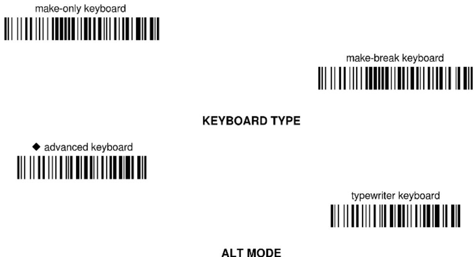
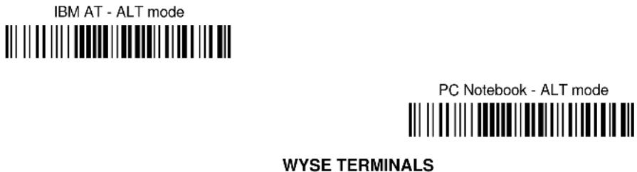
The ALT-mode selection allows barcodes sent to the PC to be interpreted correctly independently from the Keyboard Nationality used. You do not need to make a Keyboard Nationality selection.
(default = Num Lock Unchanged). Make sure the Num Lock key on your keyboard is ON.


4.5 USB Reader Configuration
The USB interface is available for PowerScan® BC 8030-BT devices and is compatible with the following Operating Systems:
Windows 98 (and later)
IBM POS for Windows
Mac OS 8.0 (and later)
4690 Operating System
USB Start-up
As with all USB devices, upon connection, the Host performs several checks by communicating with the device. During this phase normal operations are suspended. Basic conditions must be met before the device is ready — the correct USB driver must be loaded.
First Start-Up
| 1 | Connect device to Host | suggested by the O.S. and should therefore be selected from the dialog box (the first time only). |
| reader LED blinks | Normally the Host supplies sufficient power to the device and the start-up phase ends correctly. | |
| Load drivers(if requested) | ||
| reader LED off - BEEP OK | In rare cases, if the Host does not supply sufficient power to the device, a dialog box will appear on the Host and the device will be blocked. In this case, disconnect the USB device cable at the Host, and then try a different USB port as indicated by the Operating System message. (The device emits the beep OK signal. You can now read codes). | |
| 2 | Select desired USB interface code(USB-KBD is default) | |
| Load drivers(if requested) | 2 At this point you can read the USB interface configuration code according to your application. Load drivers from the O.S. (if requested). When configuring the USB-COM interface, the relevant files and drivers must be installed from the USB Device Installation software, which can be downloaded from the web page http://www.scanning.datalogic.com | |
| Read test codes.Device is READY |
The device is ready. Successive start-ups will automatically recognize the previously loaded drivers.
USB
USB-KBD

USB-KBD-ALT-MODE

USB-KBD-APPLE

USB-COM*

USB-IBM-Table Top

USB-IBM-Hand Held

* When configuring USB-COM, the relevant files and drivers must be installed from the USB Device Installation software, which can be downloaded from the web site http://www.scanning.datalogic.com.
4.6 Changing Default Settings
Once your reader is setup, you can change the default parameters to meet your application needs. Refer to the preceding paragraphs for initial configuration in order to set the default values and select the interface for your application.
In this manual, the configuration parameters are divided into logical groups making it easy to find the desired function based on its reference group.
The first four groups are for Standard Interface parameter configuration for PowerScan BT8300/BC 8080-BT configurations only:
- RS-232
- USB
- WEDGE
- PEN EMULATION
The following parameter groups are common to all interface applications:
DATA FORMAT parameters regard the messages sent to the Host system for all interfaces except Pen Emulation.
POWER SAVE manages overall current consumption in the reading device.
READING PARAMETERS control various operating modes and indicator status functioning.
DECODING PARAMETERS maintain correct barcode decoding in certain special reading conditions.
CODE SELECTION parameters allow configuration of a personalized mix of codes, code families and their options.
ADVANCED FORMATTING PARAMETERS allow code concatenation and advanced formatting of messages towards the Host. It cannot be used with Pen Emulation connections.
RADIO PARAMETERS allow configuration of radio control parameters.
BLUETOOTH PARAMETERS provide options for configuring Bluetooth parameters.
DISPLAY PARAMETERS (some BT8300 series models only) allow configuration of reader display parameters.
RS-232 PARAMETERS
PowerScan® BT8300/BC 8030-BT configurations only
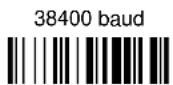
| BAUD RATE | ||
| PARITY | ||
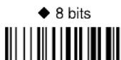
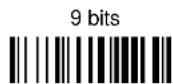
| DATA BITS | ||
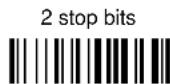
| STOP BITS | ||
| HANDSHAKING | ||
| INTER-CHARACTER DELAY | ||
| SERIAL TRIGGER LOCK |
- Read the Enter Configuration code ONCE, available at the top of each page.
- Read configuration codes from the desired groups.

= Read the code and follow the procedure given

= Default value
- Read the Exit and Save Configuration code ONCE, available at the top of each page.
Enter Configuration

RS-232
Exit and Save Configuration

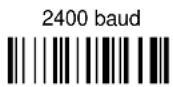
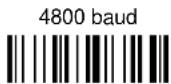
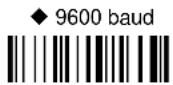
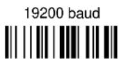
BAUD RATE

PARITY


DATA BITS

Enter Configuration Exit and Save Configuration

RS-232

STOP BITS

HANDSHAKING

hardware (RTS/CTS)


See par. 5.1.1 for details.
INTER-CHARACTER DELAY

delay between characters transmitted to Host

Read 2 numbers from the table where:
00 = DELAY disabled
01-99 = DELAY from 1 to 99 milliseconds
◆ delay disabled
SERIAL TRIGGER LOCK

enable and select characters

Read 2 characters from the Hex/Numeric table in the range 00-FE where:
- First Character enables device trigger
– Second Character inhibits device trigger until the first character is received again.
USB PARAMETERS
| USB-COM | ||
| HANDSHAKING | ||
| INTER-CHARACTER DELAY | ||
| SERIAL TRIGGER LOCK | ||
| USB-KBD | ||
| Keyboard Nationality | ||
| Inter-character delay | ||
| Inter-code Delay | ||
| USB keyboard speed | ||
| USB-IBM | ||
| No parameter selection required. |
- Read the Enter Configuration code ONCE, available at the top of each page.
- Read configuration codes from the desired groups.

= Read the code and follow the procedure given

= Default value
- Read the Exit and Save Configuration code ONCE, available at the top of each page.
Enter Configuration

USB-KBD
Exit and Save Configuration

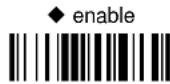
HANDSHAKING
◆ disable

hardware (RTS/CTS)

software (XON/XOFF)

RTS always ON

See par. 5.1.1 for details.
INTER-CHARACTER DELAY
delay between characters transmitted to Host


Read 2 numbers from the table where:
00 = DELAY disabled
01-99 = DELAY from 1 to 99 milliseconds
◆ delay disabled
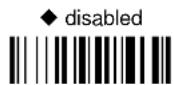
SERIAL TRIGGER LOCK
◆ disabled


enable and select characters

Read 2 characters from the Hex/Numeric table in the range 00-FE where:
- First Character enables device trigger
– Second Character inhibits device trigger until the first character is received again.
KEYBOARD NATIONALITY
Not Available for USB-KBD-ALT-MODE Interface
This parameter default value is restored through the Interface Selection code and not Restore Default.


Enter Configuration

USB-KBD
Exit and Save Configuration

The following Japanese and Eastern Block Keyboard Nationality selections are valid only for IBM AT compatible PCs.


Slovenian, Croatian, Serbian (Latin)


INTER-CHARACTER DELAY
delay between characters transmitted to Host


Read 2 numbers from the table where:
00 = DELAY disabled
01-99 = DELAY from 1 to 99 milliseconds
◆ delay disabled
INTER-CODE DELAY
delay between codes transmitted to Host


Read 2 numbers from the table where:
00 = DELAY disabled
01-99 = DELAY from 1 to 99 seconds
◆ delay disabled
USB KEYBOARD SPEED
Normal

Fast

WEDGE PARAMETERS
PowerScan® BT8300/BC 8030-BT configurations only
| KEYBOARD NATIONALITY | ||
| CAPS LOCK | ||
| CAPS LOCKAUTO-RECOGNITION | ||
| NUM LOCK | ||
| INTER-CHARACTER DELAY | ||
| INTER-CODE DELAY | ||
| KEYBOARD SETTING | ||
| CONTROL CHARACTEREMULATION |
- Read the Enter Configuration code ONCE, available at the top of each page.
- Read configuration codes from the desired groups.

= Read the code and follow the procedure given

= Default value
- Read the Exit and Save Configuration code ONCE, available at the top of each page.
KEYBOARD NATIONALITY
Belgian

English (UK)

French

German

Italian

Spanish

Swedish

◆ USA

The Japanese and Eastern Block Keyboard Nationality selections are valid only for IBM AT compatible PCs.
Japanese

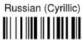
Russian (Latin)

Russian (Cyrillic)

Hungarian

Slovenian, Croatian,
Serbian (Latin)

Romanian

Czech Republic

CAPS LOCK
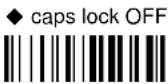

Select the appropriate code to match your keyboard caps lock status.
NOTE: Caps lock manual configuration is ignored when Caps Lock Auto-Recognition is enabled.
For PC Notebook interface selections, the caps lock status is automatically recognized; therefore this command is not necessary.
CAPS LOCK AUTO-RECOGNITION (IBM AT COMPATIBLE ONLY)

NUM LOCK

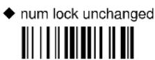
This selection is used together with the Alt Mode interface selection for AT or Notebook PCs.
It changes the way the Alt Mode procedure is executed; therefore it should be set as follows:
- if your keyboard Num Lock is normally on use num lock unchanged
- if your keyboard Num Lock is normally off use toggle num lock
In this way the device will execute the Alt Mode procedure correctly for your application.
INTER-CHARACTER DELAY

delay between characters transmitted to Host

Read 2 numbers from the table where:
00 = DELAY disabled
01-99 = DELAY from 1 to 99 milliseconds
◆ delay disabled
INTER-CODE DELAY
delay between codes transmitted to Host


Read 2 numbers from the table where:
00 = DELAY disabled
01-99 = DELAY from 1 to 99 seconds
◆ delay disabled
KEYBOARD SETTING
ALPHANUMERIC KEYBOARD SETTING
The device (reader or cradle) can be used with terminals or PCs with various keyboard types and nationalities through a simple keyboard setting procedure.
The type of computer or terminal must be selected before activating the keyboard setting command.
Keyboard setting consists of communicating to the device how to send data corresponding to the keyboard used in the application. The keys must be set in a specific order.
Press and release a key to set it.
Some characters may require more than one key pressed simultaneously during normal use (refer to the manual of your PC or terminal for keyboard use). The exact sequence must be indicated to the reader in this case pressing and releasing the different keys.
Example:
If one has to press the "Shift" and "4" keys simultaneously on the keyboard to transmit the character "\" to the video, to set the "\", press and release "Shift" then press and release "4".
Each pressed and released key must generate an acoustic signal on the device; otherwise repress the key. Never press more than one key at the same time, even if this corresponds to the normal use of your keyboard.
Press "Backspace" to correct a wrong key entry. In this case the device emits 2 beeps.
NOTE: "CAPS LOCK" and "NUM LOCK" must be off before starting the keyboard setting procedure. "SHIFT" must be repressed for each character and cannot be substituted by "CAPS LOCK".

setting the alphanumeric keyboard

Read the code above.
Press the keys shown in the following table according to their numerical order.
Some ASCII characters may be missing as this depends on the type of keyboard: these are generally particular characters relative to the various national symbologies. In this case:
- The first 4 characters (Shift, Alt, Ctrl, and Backspace) can only be substituted with keys not used, or substituted with each other.
- characters can be substituted with other single symbols (e.g. "SPACE") even if not included in the barcode set used.
- characters can be substituted with others corresponding to your keyboard.
The device signals the end of the procedure with 2 beeps indicating the keys have been registered.
KEYBOARD SETTING (continued)
Do not place the reader onto the BC 8030-BT cradle during this procedure. Otherwise, the battery charging will occur modifying the LEDs functioning.
CONTROL CHARACTER EMULATION
◆ Ctrl + Shift + Key

Ctrl + Key

PEN EMULATION
PowerScan® BT8300/BC 8030-BT configurations only
| OPERATING MODE | ||
| MINIMUM OUTPUT PULSE | ||
| CONVERSION TO CODE 39 AND CODE 128 | ||
| OVERFLOW | ||
| OUTPUT LEVEL | ||
| IDLE LEVEL | ||
| INTER-BLOCK DELAY |
- Read the Enter Configuration code ONCE, available at the top of each page.
- Read configuration codes from the desired groups.
◆ = Default value
- Read the Exit and Save Configuration code ONCE, available at the top of each page.
The operating mode parameters are complete commands and do not require reading the Enter and Exit configuration codes.
OPERATING MODE
◆ interpret mode

Interprets commands without sending them to the decoder.
transparent mode

Sends commands to the decoder without interpreting them.
MINIMUM OUTPUT PULSE
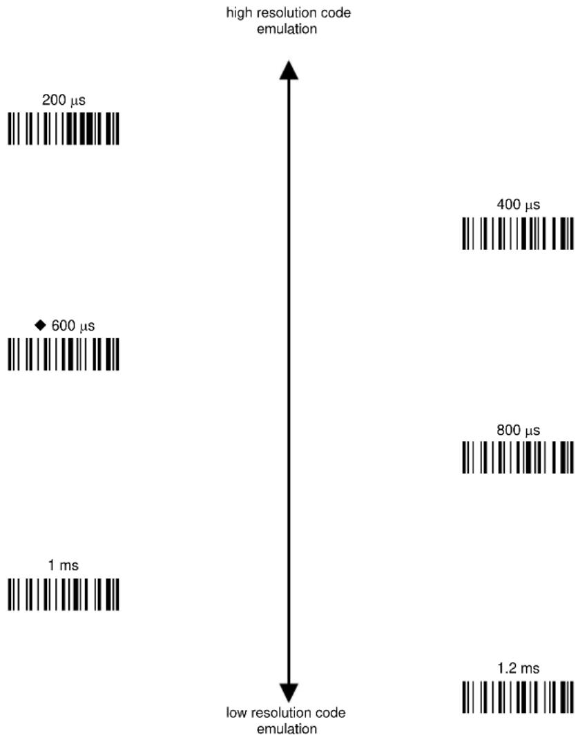
bar
| Resolution Code Emulation | Time (ms) | | ------------------------- | --------- | | High Resolution Code Emulation | 200 | | High Resolution Code Emulation | 600 | | High Resolution Code Emulation | 1 | | Low Resolution Code Emulation | 400 | | Low Resolution Code Emulation | 800 | | Low Resolution Code Emulation | 1.2 |See par. 5.2.1 for details.
CONVERSION TO CODE 39 AND CODE 128
◆ enable conversion to Code 39

Converts codes read into Code
39 format.
enable conversion to Code 128

Converts codes read into Code
128 format.
See par. 5.2.2 for details.
OVERFLOW
narrow

◆ medium

wide

See par. 5.2.2 for details.
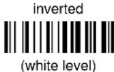
OUTPUT LEVEL
normal

(white = logic level 0)
inverted

(white = logic level 1)
See par. 5.2.4 for details.
IDLE LEVEL
◆ normal

(black level)
See par. 5.2.4 for details.
INTER-BLOCK DELAY
delay between character blocks transmitted to Host


Read 2 numbers from the table where:
00 = DELAY disabled
01-99 = DELAY from .1 to 9.9 seconds
◆ delay disabled
See par. 5.2.5 for details.
DATA FORMAT
NOT FOR PEN INTERFACES
| ⊙ | CODE IDENTIFIER | ⊙ |
| ⊙ | CRADLE CODE IDENTIFIER | ⊙ |
| ⊙ | READER CODE IDENTIFIER | ⊙ |
| ⊙ | CUSTOM CODE IDENTIFIER | ⊙ |
| ⊙ | CRADLE HEADER | ⊙ |
| ⊙ | READER HEADER | ⊙ |
| ⊙ | CRADLE TERMINATOR | ⊙ |
| ⊙ | READER TERMINATOR | ⊙ |
| ⊙ | SPECIAL KEYS | ⊙ |
| ⊙ | FIELD ADJUSTMENT | ⊙ |
| ⊙ | FIELD ADJ. CHARACTER | ⊙ |
| ⊙ | CRADLE CODE LENGTH | ⊙ |
| ⊙ | READER CODE LENGTH | ⊙ |
| ⊙ | CHARACTER REPLACEMENT | ⊙ |
| ⊙ | ADDRESS STAMPING | ⊙ |
| ⊙ | ADDRESS DELIMITER | ⊙ |
| ⊙ | TIME STAMPING | ⊙ |
| ⊙ | TIME STAMPING DELIMITER | ⊙ |
- Read the Enter Configuration code ONCE, available at the top of each page.
- Read configuration codes from the desired groups.

= Read the code and follow the procedure given

= Default value
- Read the Exit and Save Configuration code ONCE, available at the top of each page.
DATA FORMAT
| CODE IDENTIFIER TABLE | |||
| CODE | AIM STANDARD | DATALOGIC STANDARD | Custom |
| 2/5 interleaved | ] I y | N | |
| 2/5 industrial | ] X y | P | |
| 2/5 normal 5 bars | ] S y | O | |
| 2/5 matrix 3 bars | ] X y | Q | |
| EAN 8 | ] E 4 | A | |
| EAN 13 | ] E 0 | B | |
| UPC A | ] X y | C | |
| UPC E | ] X y | D | |
| EAN 8 with 2 ADD ON | ] E 5 | J | |
| EAN 8 with 5 ADD ON ] E 6 K | |||
| EAN 13 with 2 ADD ON ] E 1 L | |||
| EAN 13 with 5 ADD ON | ] E 2 | M | |
| UPC A with 2 ADD ON | ] X y | F | |
| UPC A with 5 ADD ON | ] X y | G | |
| UPC E with 2 ADD ON | ] X y | H | |
| UPC E with 5 ADD ON | ] X y | I | |
| Code 39 | ] A y | V | |
| Code 39 Full ASCII | ] A y | W | |
| CODABAR | ] F y | R | |
| ABC CODABAR | ] X y | S | |
| Code 128 | ] C y | T | |
| EAN 128 | ] C y | k | |
| ISBT 128 | ] C4 | f | |
| Code 93 | ] G y | U | |
| CIP/39 | ] X y | Y | |
| CIP/HR | ] X y | e | |
| Code 32 | ] X y | X | |
| MSI | ] M y | Z | |
| Code 11 | ] H y | b | |
| Code 16K | ] K 0 | p | |
| Code 49 | ] T y | q | |
| GS1 DataBarTM Expanded Linear and Stacked | ] e 0 | t | |
| GS1 DataBar Limited ] e 0 v | |||
| GS1 DataBar 14 Linear and Stacked | ] e 0 | u | |
- AIM standard identifiers are not defined for all codes: the X identifier is assigned to the code for which the standard is not defined. The y value depends on the selected options (check digit tested or not, check digit tx or not, etc.).
- When customizing the Datalogic Standard code identifiers, 1 or 2 identifier characters can be defined for each code type. If only 1 identifier character is required, the second character must be selected as FF (disabled).
- The code identifier can be singly disabled for any code by simply selecting FF as the first identifier character.
• Write in the Custom character identifiers in the table above for your records.
Enter Configuration Exit and Save Configuration

DATA FORMAT

CRADLE CODE IDENTIFIER
◆ disable

Datalogic standard

AIM standard

custom

READER CODE IDENTIFIER
This parameter forces the reader to insert a code identifier. This feature acts similarly to the Cradle Code Identifier starting on page 42, but is specific to the DK model.
◆ disable

Datalogic standard

AIM standard

custom

For more information on this feature see par. 5.17.2. See also "Message Formatting" in par. 6.1 and par. 6.2.
CUSTOM CODE IDENTIFIER

define custom code identifier(s)

① Read the above code.
(Code Identifiers default to Datalogic standard, see table on previous page).
② Select the code type from the code table in Appendix B for the identifier you want to change.
③ You can define 1 or 2 identifier characters for each code type. If only 1 identifier character is required, the second character must be selected as FF (disabled). Read the hexadecimal value corresponding to the character(s) you want to define as identifiers for the code selected in step ②: valid characters are in the range 00-FD.
Example: To define Code 39 Code Identifier = @

CRADLE HEADER
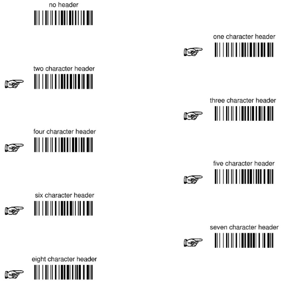
After selecting one of the desired Header codes, read the character(s) from the HEX table. Valid characters are in the range 00-FE. For Wedge and USB-KBD interfaces, it is also possible to read the Special Key(s) on page 49.
Example:

For more details see par. 5.3.1 and par. 5.3.2.
READER HEADER
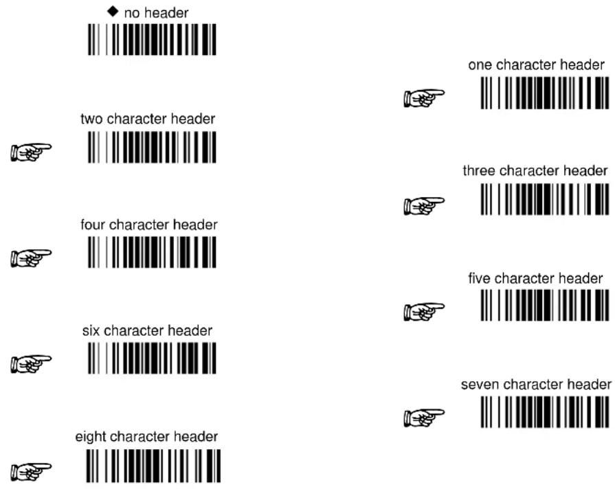
After selecting one of the desired Header codes, read the character(s) from the HEX table. Valid characters are in the range 00-FE. For Wedge and USB-KBD interfaces, it is also possible to read the Special Key(s) on page 49.
Example:

For more details see par. 5.3.1 and par. 5.3.2. See also "Message Formatting" in par. 6.1 and 6.2.
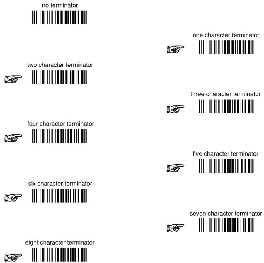
CRADLE TERMINATOR
bar
| Number of Character Terminators | Count | | ------------------------------- | ----- | | no terminator | 1 | | two character terminator | 1 | | four character terminator | 1 | | six character terminator | 1 | | eight character terminator | 1 |After selecting one of the desired Header codes, read the character(s) from the HEX table. Valid characters are in the range 00-FE. For Wedge and USB-KBD interfaces, it is also possible to read the Special Key(s) on page 49.
Example:

For more details see par. 5.3.1 and par. 5.3.2.
READER TERMINATOR
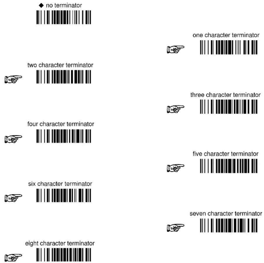
After selecting one of the desired Header codes, read the character(s) from the HEX table. Valid characters are in the range 00-FE. For Wedge and USB-KBD interfaces, it is also possible to read the Special Key(s) on page 49.
Example:

For more details see par. 5.3.1 and par. 5.3.2. See also "Message Formatting" in par. 6.1 and par. 6.2.
SPECIAL KEYS
Available only for Wedge IBM AT-PS/2 and USB-KBD Interfaces

NOTE
It is necessary to define each Special Key by following the procedure given in par. 5.3.2.
Select one or more of the following Special Keys according to your needs.
Special Key 1

Special Key 2

Special Key 3

Special Key 4

Special Key 5

FIELD ADJUSTMENT
◆ disable field adjustment

Field adjustment allows a number of characters n, to be added to or subtracted from the barcode read. The adjustment can be different for each enabled code type. To define the field adjustment:
① Read the enable field adjustment code:

② Select the code type from the Code Identifier Table in Appendix B.
③ Select the type of adjustment to perform:
right addition

right deletion

left addition

left deletion

④ Read a number in the range 01 - 32 from the Hex/Numeric Table to define how many characters to add or delete:
Conditions:
- Adjustment is only performed on the barcode data, the Code Identifier and Code Length Transmission fields are not modified by the field adjustment parameter.
- If the field setting would subtract more characters than exist in the barcode, the subtraction will take place only to code length 0.
- You can set up to a maximum of 10 different field adjustments on the same barcode family or on different barcode families.
Example: To add 4 characters to the right of Standard Code 39 Codes:

FIELD ADJUSTMENT CHARACTER
① Read the field adjustment character code:

② Read the hexadecimal value corresponding to the character you want to use for field adjustment. Valid characters are in the range 00-FE. For Wedge and USB-KBD interfaces, it is also possible to read the Special Key(s) on page 49.
Example:
To define the field adjustment character = A:

CRADLE CODE LENGTH


The code length is transmitted in the message after the Headers and Code Identifier characters. The code length is calculated after performing any field adjustment operations.
READER CODE LENGTH


For more information on this feature see par. 5.17.3. See also "Message Formatting" in par. 6.1 and par. 6.2.
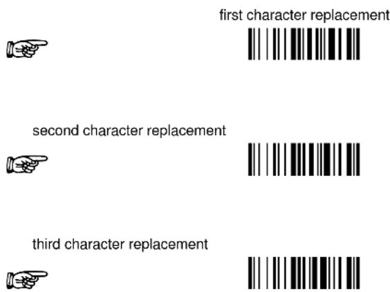
CHARACTER REPLACEMENT
◆ disable character replacement

This parameter allows up to three characters to be replaced from the barcode read. These substitutions are stored in memory. To define each character replacement:
① Read one of the following character replacement codes:
② From the Code Identifier Table in Appendix B, read the Code Identifier for the desired code family. 0 = character replacement will be effective for all code families.
③ From the Hex/Numeric Table read two characters corresponding to the Hex value (00-FE), which identifies the character to be replaced. For Wedge and USB-KBD interfaces, it is also possible to read the Special Key(s) on page 49.
④ From the Hex/Numeric Table read two characters corresponding to the Hex value (00-FE), which identifies the new character to replace. For Wedge and USB-KBD interfaces, it is also possible to read the Special Key(s) on page 49.
FF = the character to be replaced will be substituted with no character, that is, it will be removed from the code.
Example:
The following strings define:
- First Character Replacement: substitution in Code 39 barcodes of all occurrences of the 0 character with the 1 character.
- Second Character Replacement: substitution in Code 39 barcodes of all occurrences of the A character with the B character.
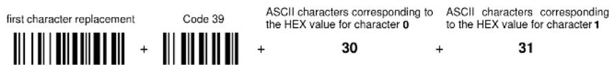
For Code 39 codes containing the string "0123", the contents transmitted will be "1123".

For Code 39 codes containing the string "ABCD", the contents transmitted will be "BBCD".
ADDRESS STAMPING
◆ disable reader address stamping

enable reader address stamping

◆ disable cradle address stamping
enable cradle address stamping

See par. 5.3.3 for details.
ADDRESS DELIMITER
◆ disable reader address delimiter

enable reader address delimiter and select characters


Read 2 HEX characters in the range 00-FE.
◆ disable cradle address delimiter

enable cradle address delimiter and select characters


Read 2 HEX characters in the range 00-FE.
See par. 5.3.4 for details.
Enter Configuration

DATA FORMAT
Exit and Save Configuration

TIME STAMPING
◆ disable

hour/minutes/seconds
month/day/year

hour/minutes/seconds
day/month/year

hour/minutes/seconds

month/day/year

day/month/year

See par. 0 for details.
TIME STAMPING DELIMITER
enable

select delimiter


◆ disable

Read 2 HEX characters in the range 00-FE.
See par. 5.3.6 for details.
POWER SAVE
| SLEEP STATE | ||
| ENTER SLEEP TIMEOUT |
- Read the Enter Configuration code ONCE, available at the top of each page.
- Read configuration codes from the desired groups.

= Read the code and follow the procedure given

= Default value
- Read the Exit and Save Configuration code ONCE, available at the top of each page.
SLEEP STATE
◆ disable

enable

See par. 5.4.1 for details.
For BT8300 series readers, sleep state is entered immediately after reading a code and is not configurable.
ENTER SLEEP TIMEOUT

enter sleep timeout

Read 2 numbers in the range 00-99:
00 = Enter Sleep state immediately
01-99 = corresponds to a max. 9.9 sec. delay before entering the Sleep state.
◆ enter sleep timeout = 0.6 sec.
See par. 5.4.2 for details.
READING PARAMETERS
| TRIGGER TYPE | ||
| TRIGGER SIGNAL | ||
| TRIGGER CLICK | ||
| TRIGGER-OFF TIMEOUT | ||
| FLASH MODE | ||
| READS PER CYCLE | ||
| SAFETY TIME | ||
| BEEPER INTENSITY | ||
| BEEPER TONE | ||
| BEEPER TYPE | ||
| BEEPER LENGTH | ||
| GOOD READ SPOT DURATION | ||
| AIMING SYSTEM | ||
| CRADLE BEEPER INTENSITY |
- Read the Enter Configuration code ONCE, available at the top of each page.
- Read configuration codes from the desired groups.

= Read the code and follow the procedure given

= Default value
- Read the Exit and Save Configuration code ONCE, available at the top of each page.
TRIGGER TYPE
◆ hardware trigger

Restores TRIGGER MODE
software trigger

Enables FLASH MODE
always on

TRIGGER SIGNAL
◆ trigger active level

trigger active pulse

See par. 5.5.1 for details.
TRIGGER CLICK
◆ disable

enable

See par. 5.5.2 for details.
TRIGGER-OFF TIMEOUT

trigger-off timeout

Read 2 numbers in the range 00-99:
00 = disables the trigger-off timeout
01-99 = corresponds to a max. 99-sec. delay after the trigger press to allow the reader to turn off automatically.
◆ trigger-off timeout disabled
See par. 5.5.3 for details.
Enter Configuration Exit and Save Configuration

READING PARAMETERS

FLASH MODE

"FLASH" ON duration


"FLASH" OFF duration

Read 2 numbers in the range 01-99:
01 to 99 = from .1 to 9.9 seconds.
◆ Flash-ON = 1 sec. Flash-OFF = 0.6 sec
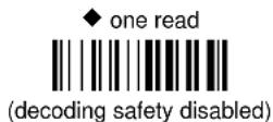
READS PER CYCLE
◆ one read per cycle

multiple reads per cycle

See par. 5.5.4 for details.
SAFETY TIME

safety time

Limits same code consecutive reading.
Read 2 numbers in the range 00-99:
00 = no same code consecutive reading until reader is removed (no decoding) for at least 400 ms.
01-99 = timeout from .1 to 9.9 seconds before a consecutive read on same code.
◆ safety time = 0.5 sec
See par. 5.5.5 for details.
Enter Configuration Exit and Save Configuration

READING PARAMETERS

BEEPER INTENSITY
* very low intensity

low intensity

medium intensity

◆ high intensity

* This sets the beeper OFF for data entry, while for all other beeper signals it has the meaning “very low intensity”. The Beeper Intensity parameter is effective for all operating conditions described in par. 7.4.
BEEPER TONE
tone 1

◆ tone 2

tone 3

tone 4

BEEPER TYPE
◆ monotone

bitonal

Enter Configuration Exit and Save Configuration

READING PARAMETERS

BEEPER LENGTH


- Read the Enter Configuration code ONCE, available at the top of each page.
- Read configuration codes from the desired groups.
◆ = Default value
- Read the Exit and Save Configuration code ONCE, available at the top of each page.
Enter Configuration Exit and Save Configuration

DECODING PARAMETERS

INK SPREAD


See par. 5.6.1 for details.
OVERFLOW CONTROL


See par. 5.6.2 for details.
INTERDIGIT CONTROL


See par. 5.6.3 for details.
DECODING SAFETY
Required number of good reads before accepting code.


PUZZLE SOLVER™
◆ disable

enable

In the case of damaged or poorly printed codes, this parameter allows reading multiple parts of the single code to reconstruct it.
To read codes using this technology, simply move the illuminated bar over the code so that each line of the code is scanned. During this process a series of brief "ticks" indicates that reading is proceeding correctly.
Conditions:
- This parameter is only valid for the following codes:
| EAN 8 without Add-on | EAN 13 without Add-on | UPC A without Add-on |
| Code 128 Code 39 | ||
• For Code 39, Check digit control is forced.
- PuzzleSolver™ is not valid for ISBT 128 code.
CODE SELECTION
| AUTO-CONFIGURATION | ||
| EAN/UPC FAMILY | ||
| 2/5 FAMILY | ||
| CODE 39 FAMILY | ||
| CODE 128 FAMILY | ||
| CODE 93 | ||
| CODABAR FAMILY | ||
| MSI | ||
| CODE 11 | ||
| CODE 16K | ||
| CODE 49 | ||
| GS1 DATABAR CODES |
- Read the Enter Configuration code ONCE, available at the top of each page.
- Read configuration codes from the desired groups.

= Read the code and follow the procedure given

= Default value
- Read the Exit and Save Configuration code ONCE, available at the top of each page.
Code selections may be performed according to two different procedures:
- Auto-configuration, allowing an automatic recognition and selection of the code families to be read;
- Manual configuration, requiring configuration and selection of each code family to be read.
AUTO-CONFIGURATION
The following codes do not require reading the Enter and Exit configuration codes.
In auto-configuration mode the reader enters a particular state, during which it reads, recognizes and saves all information received from the decoding of an existing code (with the exception of MSI, Code 49 and Code 16k code types). In this way, the code families will be automatically configured.
It is possible to configure up to 10 code types, whose length is variable and check digit ignored. If reading different codes belonging to the same family, information about the last code will overwrite the information about the previous one.
Follow the given procedure to auto-configure the desired code families:

CAUTION
If no code is read during the auto-configuration procedure (step ②), the configuration will be empty and therefore the reader will be unable to read codes.
① Read the following code to enter the auto-configuration mode:

auto-configuration

② Read an existing code belonging to the code families that you need to configure.
③ Read the following code to save the configuration automatically and return to the reader's normal functioning:
save auto-configuration

If you need to change the configuration, repeat the auto-configuration procedure, follow the manual configuration by setting the parameters for each single code family or read the "Restore Default" code on page 146. Be careful that in the latter case all reader parameters will be restored.
DISABLE ALL CODE FAMILIES


NOTE
The reader allows up to 10 code selections. This does not limit the number of CODES enabled to 10, as it depends on the code family.
SINGLE SELECTIONS =
• ONE combination code from the EAN family
• ONE code from the 2/5 family
Example
5 code selections: 1.
2/5 Interleaved
2.
2/5 Industrial
-
Code 128 + EAN 128
-
Code 39 Full ASCII + Code 32
5.
UPC A/UPC E
6.
etc.
In this section all SINGLE code selections are underlined and in bold.
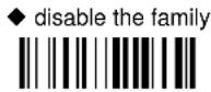
EAN/UPC FAMILY
disable the family

① Read the desired family code
NOTE: Since the EAN/UPC without ADD ON code selection is enabled by default, to correctly enable another selection, first disable the family.
EAN 8/EAN 13/UPC A/UPC E with and without ADD ON

WITHOUT ADD ON
◆ EAN 8/EAN 13/UPC A/UPC E

EAN 8/EAN 13

UPC A/UPC E

Enter Configuration Exit and Save Configuration

CODE SELECTION

WITH ADD ON 2 AND 5
EAN 8/EAN 13/UPC A/UPC E
EAN 8/EAN 13

UPC A/UPC E

WITH ADD ON 2 ONLY
EAN 8/EAN 13

UPC A/UPC E

WITH ADD ON 5 ONLY
EAN 8/EAN 13

UPC A/UPC E

WITH AND WITHOUT ADD ON
◆ EAN/UPC with and without ADD ON no
Autodiscrimination

EAN/UPC Autodiscrimination ADD ON by
Prefix

By setting the EAN/UPC Autodiscrimination ADD ON by Prefix, the desired prefixes must be selected by reading the corresponding codes given in the following section, since no prefix is configured by default.
SELECT EAN/UPC PREFIXES

NOTE
When scanning the following codes, barcodes starting with the selected prefixes will be read and transmitted only if the ADD ON is present. If no ADD ON is found, the barcode will not be read. Barcodes starting with different characters are read regardless of ADD ON presence and transmitted always without ADD ON.
◆ Cancel All Selections

OR
select one or more of the following prefixes:
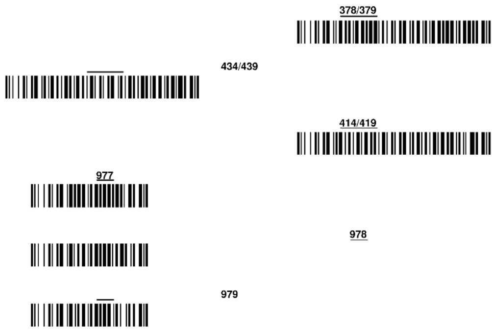
bar
| Label | Value | | --------- | ------- | | 434/439 | 378/379 | | 977 | 414/419 | | 978 | 978 | | 979 | |The commands above are not mutually exclusive. They can be used to configure more than one set of prefixes simultaneously.
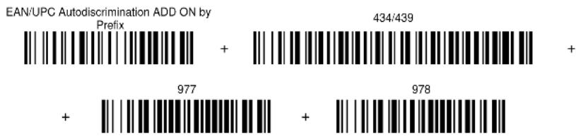
Example:
The following string allows reading and transmitting with ADD ON all EAN/UPC starting with the 434/439, 977 and 978 prefixes:
- EAN/UPC Autodiscrimination ADD ON by Prefix.
- 434/439: enables reading and transmission with ADD ON of all EAN/UPC barcodes starting with 434/439 prefixes.
- 977: enables reading and transmission with ADD ON of all EAN/UPC barcodes starting with 977 prefix.
- 978: enables reading and transmission with ADD ON of all EAN/UPC barcodes starting with 978 prefix.
Enter Configuration Exit and Save Configuration

CODE SELECTION

bar
| Prefix | Value | | ------ | ----- | | + | 434/439 | | + | 977 | | + | 978 |To clear the current prefix selections:
- Cancel all Selections

EAN/UPC CHECK DIGIT TX SELECTIONS
For each code type in this family you can choose to transmit the check digit or not
CHECK DIGIT TRANSMISSION

NO CHECK DIGIT
TRANSMISSION


CONVERSION OPTIONS
UPC E to UPC A conversion

UPC E to EAN 13 conversion

UPC A to EAN 13 conversion

EAN 8 to EAN 13 conversion

Enable only ISBN conversion

Enable only ISSN conversion

Enable both ISBN and ISSN conversion

Disable both ISBN and ISSN conversion

2/5 FAMILY
disable the family

① Read the desired family code


The pharmaceutical code below is part of the 2/5 family but has no check digit or code length selections.

French pharmaceutical code
② Read a check digit selection
CHECK DIGIT TABLE
no check digit control

◆ check digit control and transmission

check digit control without transmission

③ Read 4 numbers for the code length where:
- First 2 digits = minimum code length.
- Second 2 digits = maximum code length.
The maximum code length is 99 characters.
The minimum code length must always be less than or equal to the maximum.
Examples:
0199 = variable from 1 to 99 digits in the code.
1010 = 10 digit code length only.
CODE 39 FAMILY
disables the family

① Read the desired family code
② Read a check digit selection
CHECK DIGIT TABLE

◆ Standard Code 39

◆ no check digit control


Full ASCII Code 39

check digit control and transmission

check digit control without transmission

The pharmaceutical codes below are part of the Code 39 family but have no check digit selections.

French pharmaceutical code

CODE LENGTH (optional)
The code length selection is valid for the entire Code 39 family
Read the code + 4 numbers for the code length where:
First 2 digits = minimum code length.
Second 2 digits = maximum code length.
The maximum code length is 99 characters.
The minimum code length must always be less than or equal to the maximum.
Examples: 0199 = variable from 1 to 99 digits in the code. 1010 = 10 digit code length only.
set code length

CODE 128 FAMILY
disable the family

① Read the desired family code
◆ Code 128

control without transmission of check digit
EAN 128

control without transmission of check digit
ISBT 128

enabling ISBT 128 automatically disables Puzzle Solver™.
Transmit GS Before Code
Code EAN 128 uses the ASCII
◆ disable

enable

If the
CODE LENGTH (optional)
The code length selection is valid for the entire Code 128 family and is calculated on the output string.
Read the code + 4 numbers for the code length where:
set code length

First 2 digits = minimum code length.
Second 2 digits = maximum code length.
The maximum code length is 99 characters.
The minimum code length must always be less than or equal to the maximum.
Examples: 0199 = variable from 1 to 99 digits in the code. 1010 = 10 digit code length only.
CODE 93
◆ disable the code

Code 93

control without transmission of check digit
CODABAR FAMILY
① Read the desired equality control code
② Read a start/stop transmission selection
START/STOP CHARACTER TRANSMISSION

Standard Codabar

no start/stop character equality control
no transmission


Standard Codabar

start/stop character equality control
transmission

The Codabar ABC code below uses a fixed start/stop character transmission selection.
Codabar ABC

no start/stop character equality control but transmission.
Codabar ABC Forced Concatenation
enable Codabar ABC with forced concatenation

non start/stop character equality control but transmission
CODE LENGTH (optional)
The code length selection is valid for the entire Codabar family
Read the code + 4 numbers for the code length where:
set code length
First 2 digits = minimum code length.
Second 2 digits = maximum code length.

The maximum code length is 99 characters.
The minimum code length must always be less than or equal to the maximum.
Examples: 0199 = variable from 1 to 99 digits in the code. 1010 = 10 digit code length only.
START/STOP CHARACTER CASE IN TRANSMISSION
The start/stop character case selections below are valid for the entire Codabar family:
transmit start/stop characters in lower case

transmit start/stop characters in upper case

MSI
◆ disable the family

Enable the code by selecting one of the check digit selections.
no check digit control

MOD10 check digit control no check digit transmission

MOD10 check digit control check digit transmission

MOD11 - MOD10 check digit control no check digit transmission

MOD11 - MOD10 check digit control check digit transmission

MOD10 - MOD10 check digit control no check digit transmission

MOD10 - MOD10 check digit control check digit transmission

Enter Configuration Exit and Save Configuration

CODE SELECTION

CODE 11
◆ disable the family

Enable the code by selecting one of the check digit selections.
no check digit control

Type C check digit control check digit transmitted

Type C check digit control check digit not transmitted

Type K check digit control check digit transmitted

Type K check digit control check digit not transmitted

Type C and Type K check digit control check digits transmitted

Type C and Type K check digit control check digits not transmitted

CODE 16K
◆ disable the code

Code 16K

To read stacked codes, simply move the reader over the code so that each line of the code is scanned. During this process a series of brief "ticks" indicates that reading is proceeding correctly.
CODE 49
◆ disable the code

Code 49

To read stacked codes, simply move the reader over the code so that each line of the code is scanned. During this process a series of brief "ticks" indicates that reading is proceeding correctly.
GS1 DATABAR™ CODES
◆ disable the family

DISABLE CODE
disable GS1 DataBar Expanded Linear and Stacked

disable GS1 DataBar Limited

disable GS1 DataBar 14 Linear and Stacked

ENABLE CODE
enable GS1 DataBar Expanded Linear and Stacked

enable GS1 DataBar Limited

enable GS1 DataBar 14 Linear and Stacked

To read stacked codes, simply move the reader over the code so that each line of the code is scanned. During this process a series of brief "ticks" indicates that reading is proceeding correctly.
ADVANCED FORMATTING
NOT FOR PEN INTERFACES
| ⊙ | CONCATENATION | ⊙ |
| ⊙ | ADVANCED FORMATTING | ⊙ |

NOTE
Please follow the setup procedure carefully for these parameters.

NOTE
The Advanced Formatting parameters may not be compatible with the IBM USB POS interface selection.
- Read the Enter Configuration code ONCE, available at the top of page.
- Read configuration codes precisely following the numbered procedure given.
= Read the code and follow the procedure given
◆ = Default value - Read the Exit and Save Configuration code ONCE, available at the top of page.
CONCATENATION


Permits the concatenation of two codes defined by code type and length. It is possible to set a timeout for the second code reading and to define code transmission if the timeout expires.
The order of transmission is CODE 1-CODE 2.
Define Concatenation
1
Code 1


Read the code type from the Code Identifier Table beginning in Appendix B.


Read a number in the range 01-99 from the Hex/Numeric Table.
2
Code 2


Read the code type from the Code Identifier Table beginning in Appendix B.


Read a number in the range 01-99 from the Hex/Numeric Table.
3
Concatenation Result Code ID


Since you can concatenate codes from different families, you must select the Code ID character of the resulting code. The Code ID character will be sent in the output message only if it is enabled according to the Code Identifier selection (Datalogic, AIM, or Custom).
4
Concatenation Timeout


Read two numbers in the range 00 to 99
00= no timeout
01-99 = timeout from 1 to 99 seconds
Define the timeout, which determines the valid waiting period between the two codes, in order to accept concatenation. If the timeout expires, the resulting action will be based on the following selection. (HHDII)
5
Transmission after Timeout
no code transmitted after timeout

only code 1 transmitted (if read) after timeout

only code 2 transmitted (if read) after timeout

either code 1 or code 2 transmitted after timeout

ADVANCED FORMATTING
Advanced formatting has been designed to offer you complete flexibility in changing the format of barcode data before transmitting it to the host system. This formatting will be performed when the barcode data meets certain criteria, which you will define in the following procedure.
Up to 4 advanced code management formats can be defined and saved in memory. For each format you must complete the entire configuration procedure:
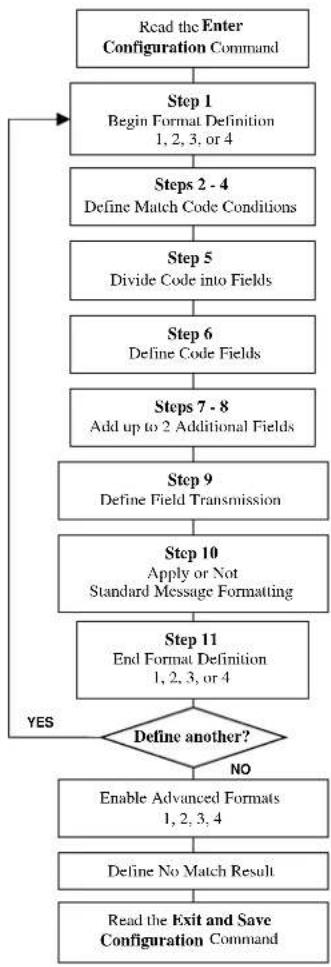
flowchart
graph TD
    A["Read the Enter Configuration Command"] --> B["Step 1 Begin Format Definition 1, 2, 3, or 4"]
    B --> C["Steps 2 - 4 Define Match Code Conditions"]
    C --> D["Step 5 Divide Code into Fields"]
    D --> E["Step 6 Define Code Fields"]
    E --> F["Steps 7 - 8 Add up to 2 Additional Fields"]
    F --> G["Step 9 Define Field Transmission"]
    G --> H["Step 10 Apply or Not Standard Message Formatting"]
    H --> I["Step 11 End Format Definition 1, 2, 3, or 4"]
    I --> J{Define another?}
    J -->|YES| B
    J -->|NO| K["Enable Advanced Formats 1, 2, 3, 4"]
    K --> L["Define No Match Result"]
    L --> M["Read the Exit and Save Configuration Command"]
1
Begin Format Definition

begin Format 1 definition


begin Format 2 definition


begin Format 3 definition

begin Format 4 definition

2
Match Code Type

match code type

Read the above code + the code type to match from the Code Identifier Table in Appendix B.
OR
any code type

3
Match Code Length

match code length

Read the above code + two numbers in the range 01 to 99 for the exact code length.
OR
any code length

4
Match with Predefined Characters


match with 1 character


match with a 2-character string


match with a 3-character string


match with a 4-character string

After selecting the predefined match code, read the character(s) from the HEX table. Range of characters = 00-FE.
Example:
Match code with the 2-character predefined string = "@@".

AND
position of first character in predefined string


Read the above code + two numbers in the range 01 to 99 representing the character position in the code where the first character of the predefined string must be found.
Read 00 if the match string can be found in any character position.
See par. 5.7.1 for details.
5
Divide Code into Fields

divide code into fields

Read one number in the range 1 to 5 to divide the code into fields.
6
Define Code Fields
define code fields
Each code field length can be set by either:
a) defining a field separator character to be found in the code itself. In this case you can choose to discard the code separator character or include it as the last character of the field.
OR BY
b) defining a match character to be found consecutively repeated in the code itself. In this case the field ends with the first character that does not match.
OR BY
c) specifying a specific character length up to the maximum of 99 characters.
OR BY
d) selecting the last field as variable length (if any).
You must define the same number of fields as selected in step 5, including fields that will not be transmitted.
DEFINE FIELD 1 BY: EITHER
a)

field separator

Read the field separator character from the HEX table. Range of characters = 00-FE.
discard separator

include separator

OR
b)

match character

Read the match character from the HEX table. Range of characters = 00-FE.
OR
c)

field length

Read two numbers in the range 01 to 99 to define the field length.
OR
d)

this is the last field (variable length)

AND
Field 1 Terminators
no field terminators


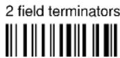
Read the field terminator character(s) from the HEX table. Valid range of characters for all readers = 00-FE. For Wedge and USB-KBD interface, it is also possible to read the Special Key(s) on page 49.
DEFINE FIELD 2 BY: EITHER

field separator

Read the field separator character from the HEX table. Range of characters = 00-FE.
discard separator

include separator

OR

match character

Read the match character from the HEX table. Range of characters = 00-FE.
OR

field length

Read two numbers in the range 01 to 99 to define the field length.
OR

this is the last field (variable length)

AND
Field 2 Terminators
no field terminators


1 field terminator


2 field terminators

Read the field terminator character(s) from the HEX table. Valid range of characters for all readers = 00-FE. For Wedge and USB-KBD interface, it is also possible to read the Special Key(s) on page 49.
DEFINE FIELD 3 BY: EITHER
a)

field separator

Read the field separator character from the HEX table. Range of characters = 00-FE. discard separator include separator


OR
b)

match character

Read the match character from the HEX table. Range of characters = 00-FE.
OR
c)

field length

Read two numbers in the range 01 to 99 to define the field length.
OR
d)

this is the last field (variable length)

AND
Field 3 Terminators
no field terminators


1 field terminator


2 field terminators

Read the field terminator character(s) from the HEX table. Valid range of characters for all readers = 00-FE. For Wedge and USB-KBD interface, it is also possible to read the Special Key(s) on page 49.
DEFINE FIELD 4 BY: EITHER
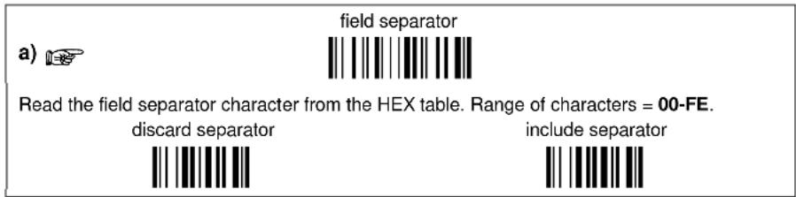
OR
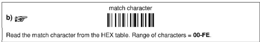
OR
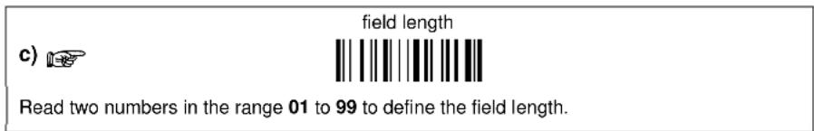
OR
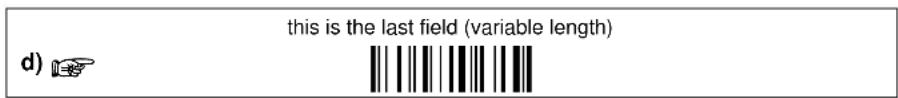
AND
Field 4 Terminators
no field terminators


Read the field terminator character(s) from the HEX table. Valid range of characters for all readers = 00-FE. For Wedge and USB-KBD interface, it is also possible to read the Special Key(s) on page 49.
DEFINE FIELD 5 BY: EITHER
a)

field separator

Read the field separator character from the HEX table. Range of characters = 00-FE.
discard separator

include separator

OR
b)

match character

Read the match character from the HEX table. Range of characters = 00-FE.
OR
c)

field length

Read two numbers in the range 01 to 99 to define the field length.
OR
d)

this is the last field (variable length)

AND
Field 5 Terminators
no field terminators


1 field terminator


2 field terminators

Read the field terminator character(s) from the HEX table. Valid range of characters for all readers = 00-FE. For Wedge and USB-KBD interface, it is also possible to read the Special Key(s) on page 49.
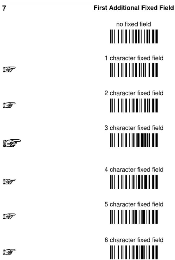
bar
7 First Additional Fixed Field | Character | First Additional Fixed Field | | :--- | :--- | | no fixed field | 1 character fixed field | | 1 | 2 character fixed field | | 2 | 3 character fixed field | | 3 | 4 character fixed field | | 4 | 5 character fixed field | | 5 | 6 character fixed field |After selecting one of the Additional Fixed Field codes, read the corresponding character(s) from the HEX table. Range of characters = 00-FE. For Wedge and USB-KBD interface, it is also possible to read the Special Key(s) on page 49.
Example:

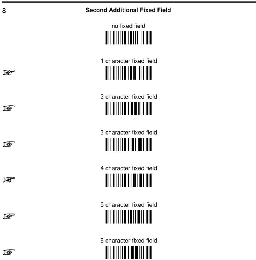
bar
8 Second Additional Fixed Field | Character Fixed Field | Number of Characters Fixed | | :--- | :--- | | 1 | 1 character fixed field | | 2 | 2 character fixed field | | 3 | 3 character fixed field | | 4 | 4 character fixed field | | 5 | 5 character fixed field | | 6 | 6 character fixed field | no fixed fieldAfter selecting one of the Additional Fixed Field codes, read the corresponding character(s) from the HEX table. Range of characters = 00-FE. For Wedge and USB-KBD interface, it is also possible to read the Special Key(s) on page 49.
Example:

9
Field Transmission
number of fields to transmit

Read one number in the range 1 to 7 for the number of fields to transmit. Include only fields to be transmitted.
Enter Configuration Exit and Save Configuration

ADVANCED FORMATTING

Field Order Transmission
Read the codes corresponding to the fields to transmit in the order in which they are to be transmitted. A field can be transmitted more than once. See example.
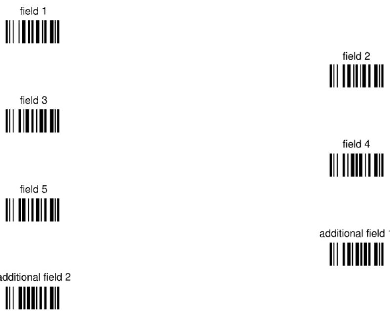
bar
| Field | Value | |-------|-------| | field 1 | 1 | | field 2 | 2 | | field 3 | 3 | | field 4 | 4 | | field 5 | 5 | | additional field 1 | 1 | | additional field 2 | 2 |Example:
The barcode is divided into 3 defined fields plus 1 additional fixed field.
Transmit in the order: Field 2, Additional Field 1, Field 1, Field 2.

10
Standard Formatting
do not apply standard formatting

apply standard formatting

POWERSCAN® D8330: After performing Advanced Formatting on the barcode read, Standard Formatting (Headers, Code Length, Code ID, Terminators) can be applied to the message to be transmitted.
POWERSCAN® BT8300: After performing Advanced Formatting on the barcode read, Standard Formatting (Code Length, Code ID) can be applied to the message to be transmitted.
11
End Format Definition
end Format 1 definition

end Format 2 definition

end Format 3 definition

end Format 4 definition

Enable Advanced Format
◆ no Advanced Formats enabled

Advanced Format 1


Advanced Format 2


Advanced Format 3


Advanced Format 4


No Match Result
clear data - no transmission

transmit data using standard format

This selection determines the action to be taken when codes read do not conform to the advanced format requisites (no match).
- Codes not matching can be ignored, cleared from memory and not transmitted.
- Codes not matching can be transmitted using the Standard formatting (Headers, Code Length, Code ID, Terminators).
RADIO PARAMETERS
| ◎ | POWER-OFF TIMEOUT | ◎ |
| ◎ | BEEPER CONTROL FOR RADIO RESPONSE | ◎ |
| ◎ | BATCH MODE | ◎ |
| ◎ | SEE ME | ◎ |
- Read the Enter Configuration code ONCE, available at the top of each page.
- Read configuration codes from the desired groups.
= Read the code and follow the procedure given
- Read the Exit and Save Configuration code ONCE, available at the top of each page.
POWER-OFF TIMEOUT

power-off timeout

Read 2 numbers in the range 00-99:
00 = Power-off disabled; reader always ready
01-99 = corresponds to a max. 99 hour delay before power-off.
◆ power-off after 4 hours.
The following batch management parameters are complete commands and do not require reading the Enter and Exit configuration codes.
start normal batch transmission

+BFlush
delete batch data

+BReset
SEE ME
disable

◆ enable

See par. 5.8.4 for details.
BLUETOOTH PARAMETERS
| ⊙ | COMMUNICATION TYPE | ⊙ |
| ⊙ | BLUETOOTH FRIENDLY NAME | ⊙ |
| ⊙ | LINK BY CONTACT | ⊙ |
| ⊙ | START UP CONNECT | ⊙ |
| ⊙ | AUTO RECONNECT | ⊙ |
| ⊙ | RECONNECT ATTEMPT INTERVAL | ⊙ |
| ⊙ | RECONNECT ATTEMPT MODE | ⊙ |
| ⊙ | POWER CLASS | ⊙ |
| ⊙ | SECURITY MODE | ⊙ |
| ⊙ | PIN LENGTH | ⊙ |
| ⊙ | PIN CODE | ⊙ |
| ⊙ | VARIABLE PIN CODE | ⊙ |
| ⊙ | DISCOVERABLE MODE | ⊙ |
| ⊙ | HID COUNTRY CODE | ⊙ |
| ⊙ | HID CAPS LOCK STATE | ⊙ |
| ⊙ | HID CAPS LOCK AUTO-RECOGNITION (IBM AT COMPATIBLE ONLY)○ | ⊙ |
| ⊙ | HID ALT MODE | ⊙ |
| ⊙ | HID INTERCHAR DELAY | ⊙ |
| ⊙ | HID SEND UNKNOWN ASCII CHAR | ⊙ |
- Read the Enter Configuration code ONCE, available at the top of each page.
- Read configuration codes from the desired groups.
= Read the code and follow the procedure given
- Read the Exit and Save Configuration code ONCE, available at the top of each page.
COMMUNICATION TYPE
To set up the PowerScan BT8300 to communicate with the BC 8030-BT, or to use standard Bluetooth profiles, scan the Communication Types below:

Serial Port Profile (Master)
Serial Port Profile (Slave)


See par. 5.9.1 for more information.
BLUETOOTH FRIENDLY NAME
You can set a meaningful name for PowerScan BT8300 that appears in the application during device discovery. The default name is the scanner name followed by its serial number: POWERSCAN BT8300 + SERIAL_NUMBER.
To set a new Bluetooth Friendly Name, scan the barcode below and follow the instructions.

Set Friendly Name

Read 2 numbers in the range 00-26 to define the Length
+
Read HEX characters to define the Bluetooth Friendly Name
Example: To set BT Friendly Name = DATALOGIC
Scan:
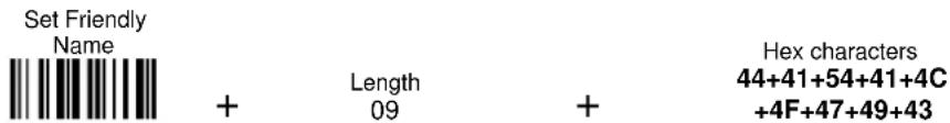
LINK BY CONTACT


See par. 5.9.2 for more information.
START UP CONNECT


See par. 5.9.4 for more information.
AUTO RECONNECT


See par. 5.9.5 for more information.
RECONNECT ATTEMPT INTERVAL


See par. 5.9.6 for more information.
RECONNECT ATTEMPT MODE


See par. 5.9.7 for more information.
POWER CLASS

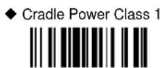


See par. 5.9.8 for more information.
SECURITY MODE

NOTE
Default Reader Security Mode = 1 in Handheld - Cradle and HID Profile; Default Reader Security Mode = 2 in Serial Port Profile (Master) and Serial Port Profile (Slave)
◆ Reader Security Mode 1

Reader Security Mode 2

Reader Security Mode 3

◆ Cradle Security Mode 1

Cradle Security Mode 2

Cradle Security Mode 3

See par. 5.9.9 for more information.
PIN LENGTH
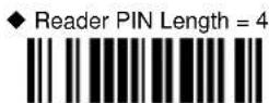

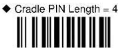
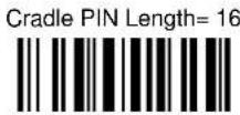
See par. 5.9.10 for more information.
PIN CODE


Set Cradle PIN Code 16

Read HEX numbers to assign a 4 or 16 character PIN Code for the PowerScan BT8300.
Example: If the PIN Length = 4 and want the new PIN Code = 5678, the input HEX numbers will be 35363738

NOTE
The default PIN code is "1234"
See par. 5.9.10 for more information.
VARIABLE PIN CODE
Some Bluetooth drivers require entering a Variable PIN Code. Scan the barcode below to set the scanner to use a variable pin code.


See par. 5.9.11 for more information.
DISCOVERABLE MODE


HID COUNTRY CODE


HID COUNTRY CODE (continued)
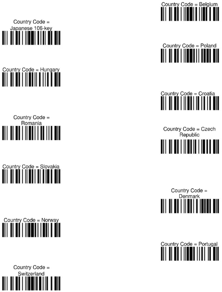
HID CAPS LOCK STATE
◆Caps Lock State =
Caps Lock OFF

Caps Lock State =
Caps Lock ON

HID CAPS LOCK AUTO-RECOGNITION
(IBM AT COMPATIBLE ONLY)


See par 5.9.12 for more information.
HID ALT MODE


See par. 5.9.13 for more information.
HID INTERCHAR DELAY
HID Interchar Delay


Read 2 numbers from the table where
00 = DELAY disable
01-99 = DELAY from 1 to 99 milliseconds
◆ Delay disable
See par. 5.9.14 for more information.
HID SEND UNKNOWN ASCII CHAR


See par. 5.10 for more information.
DISPLAY and KEYPAD PARAMETERS (3-Key Model)
PowerScan® BT8300 Series Display and 3-Key readers only
| ⊙ | DATE AND TIME | ⊙ |
| ⊙ | CONTRAST | ⊙ |
| ⊙ | FONT SIZE | ⊙ |
| ⊙ | BACKLIGHT | ⊙ |
| ⊙ | DISPLAY OFF TIMEOUT | ⊙ |
| ⊙ | DISPLAY MODE | ⊙ |
| ⊙ KEYPAD ⊙ | ||
- Read the Enter Configuration code ONCE, available at the top of each page.
- Read configuration codes from the desired groups.
= Read the code and follow the procedure given
- Read the Exit and Save Configuration code ONCE, available at the top of each page.
DISPLAY PARAMETERS
DATE AND TIME

Read 6 numbers for DDMMYY

Read 4 numbers for HHMM
CONTRAST


Read the code until the desired contrast is reached.
FONT SIZE


BACKLIGHT


DISPLAY-OFF TIMEOUT

Read 2 numbers in the range 00-99:
00 = disables display timeout (always on)
01 to 99 = timeout from 1 to 99 seconds.
◆ display-off after 8 seconds.
◆ delay disabled
DISPLAY MODE

clear display after decode


See par. 5.10.1 for details.
KEYPAD PARAMETERS
KEYPAD
disable 3-key keypad

◆ enable 3-key keypad and select characters


Read 3 HEX characters in the range 00-FE, corresponding to the left, center and right keys respectively.
FF = KeyID disabled
◆ left = '<'
center = '='
right = '>'
See par. 6.3 for details.
DISPLAY and KEYPAD PARAMETERS (16-Key Model)
PowerScan ^® BT8300-DK 16-Key readers only
| ◎ | KEYPAD PARAMETERS | ◎ |
| ◎ | DISPLAY PARAMETERS | ◎ |
| ◎ | DATA FORMAT | ◎ |
| ◎ | OPERATIVE MODE | ◎ |
| ◎ | QTY/CODE MODE | ◎ |
- Read the Enter Configuration code ONCE, available at the top of each page.
- Read configuration codes from the desired groups.
= Read the code and follow the procedure given
- Read the Exit and Save Configuration code ONCE, available at the top of each page.
KEYPAD PARAMETERS
16-KEY KEYPAD ENABLE
The software has the capability to disable or enable the 16-key keyboard.
16-key Keypad Disabled

◆ 16-Key Keypad Enabled

INTERKEY TIMEOUT
The 16-key keypad is organized like a cell phone, with multi-tap access to alpha characters on numeric keys. In alphabetic mode (entered by toggling the Shift key), the keys must be pressed once, twice, or more to obtain the desired letter. See page 153 for more information about the keypad.
This command allows you to specify the time which occurs between a key press, and the confirmation of the letter by the scanner (when in alpha mode). The timeout can be configured in steps of 0,5 second.
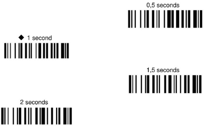
KEY PRESS SOUND
Enable/disable the KEY press sound ('click').
Key Press Sound Disabled

◆ Key Press Sound Enabled

FUNCTION KEY PROGRAMMING
There are four function keys, F1, F2, F3, F4, plus the SHIFT key ( ), which can be defined as Function 5. Each of these keys can be programmed to perform a user-assigned function. This is done by associating a function key with an entry in the String Table, which is a database resident on the 16-key PowerScan. You can select either a predefined command or define your own custom string. See the "String Table" command on page 114 to define customized strings for the String Table. See the "Shift Key Programming" command on page 116 to define the SHIFT key as F5.
Each function key has an associated mnemonic label which shows in the display when active. The default labels are shown in the table below. To program the function key labels, see "Function Key Label" command on page 115.
The following table shows the list of commands and available strings.
| CMD_ID | Name | Function | Default Label |
| 0 | ENTER CMD | (Same as ENTER_KEY) | ← |
| 1 | String 1 | Associate with String 1 from the String Table | |
| 2 | String 2 | Associate with String 2 from the String Table | |
| 3 | String 3 | Associate with String 3 from the String Table | |
| 4 | String 4 | Associate with String 4 from the String Table | |
| 5 | String 5 | Associate with String 5 from the String Table | |
| 6 | Backlight CMD | Toggle the backlight ON/OFF | Lgt |
| 7 | Clear CMD | Cancel ALL data entered in the edit field | CLR |
| 8 | Backspace CMD | Delete one char per key press from an edit field | ← |
| 9 | Recall Last CMD | If pressed once it recalls from memory the last code sent out; If pressed twice it will attempt to resend the last sent code | Rec |
| A | Show Watch | Display the internal time | Tim |

define function key

① Read the above code to associate a Function Key or the Shift key (if defined as F5).
② Specify which Function Key you want to associate (F1 - F4 or Shift ↑ F5) by scanning a barcode (1-5) from the hex numeric table in the back of this manual.
③ Select the label command you want to associate from the table on page 114. Scan a barcode from the hex numeric table corresponding to the command ID (0-A)
Example: To define Function Key 1= Clear command
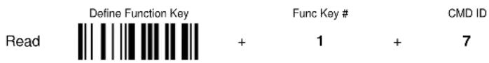
STRING TABLE
The Powerscan 16-key model allows you to define a String Table, a database with room for five entries, from String1 to String5, which can be recalled using a Function Key. This is done with Function Key Programming, described on page 114.
The string can be a single 'char'. Default = empty strings.


① Read the above code.
② Select the string number you want to add by scanning a barcode (1 - 5) from the hex numeric table in the back of this manual.
③ Select the desired string length by scanning a barcode (0 - A) from the hex numeric table.
④ Define the label string by scanning characters or numerals from the hex numeric table.
Example: To define String 1 = DATALOGIC

FUNCTION KEY LABEL
This item allows the user to change the default mnemonic label associated to each individual function key (F1 – F4). This is done by programming a short acronym string or symbol to be shown in the bottom of the display. The purpose of the label is to serve as an indication of the programmed function of the Function Key below it. To program the Function Keys themselves, see the "Function Key Programming" command on page 114.
NOTE: Function key label length is fixed at 4 characters and is not programmable.

define function key label

① Read the above code.
② Specify which Function Key Label you want to change by scanning a barcode (1-4) from the hex numeric table in the back of this manual.
③ Define the label string by scanning 4 characters from the Hex numeric table.
Example: To define Function Key 2 label = D

LOWER CASE
This function enables/disables the capability to use the SHIFT key to switch to Lower Case (alphanumeric) mode. When enabled, the indication in the upper right corner of display is 'ab'.
◆ Disable Lower Case

Enable Lower Case

SHIFT KEY PROGRAMMING
The SHIFT key ( ) can be programmed to perform a function different than its standard (which is to toggle from numeric to alpha mode). After the Shift Key has been defined as Function 5, refer to the “Function Key Programming” command on page 114 for options.
◆ SHIFT KEY Normal
mode

SHIFT KEY Function 5

ECHO
This function enables/disables the keypad echo. It works only when the scanner is in simple data input mode (no QTY/CODE).
◆ Full keypad echo

No echo on Function Key

No echo on any key

DISPLAY PARAMETERS
DATE AND TIME
set date


Read 6 numbers for DDMMYY

set time

Read 4 numbers for HHMM
CONTRAST
lighter

darker

Read the code until the desired contrast is reached.
DISPLAY-OFF TIMEOUT

timeout

Read 2 numbers in the range 00-99:
00 = disables display timeout (always on)
01 to 99 = timeout from 1 to 99 seconds.
◆ display-off after 8 seconds.
◆ delay disabled
LAST CODE SHOWN TIMEOUT
After the CODE transmission, the last code read will be shown on the display for a configurable timeout (LAST CODE SHOWN TOUT).
NOTE: Just as in the settings for the standard Powerscan, the display has an active timeout before going in OFF state. This timeout has a higher priority than the LAST CODE SHOWN TOUT, so the two parameters should be combined to get the desired result.


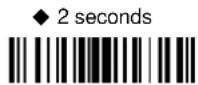


BACKLIGHT
This feature defines the behavior of the 16-key scanner Backlight (both for display and keyboard).
◆ All backlighting disabled

Display enabled, keyboard disabled

Display disabled, keyboard enabled (rarely used)

Display enabled, keyboard enabled

SCREEN REFRESH
Disable screen refresh at the end of keyboard data input. This feature works only in Simple Data Input Mode (no QTY/CODE).
NOTE: When using two-way communication in which the scanner displays data received from the host, the refresh screen should normally be disabled to avoid overwriting messages coming from the host.


DATA FORMAT
Keypad Specific Formatting
KEYBOARD DATA FORMAT ENABLE/DISABLE
This feature allows you to enable/disable specific formatting for data entered by keyboard and barcode labels read by the scan engine.
Use this command only if you require differentiation in formatting between scanned barcodes and data that is input from the keyboard. Refer to the standard Data Format section for other formatting options.
NOTE: if you enable different formatting you must define the desired format, otherwise the default data format will be used.
See par. 5.17.1 in the References section for a more detailed description of this feature.
◆ Disabled
(Same as Code)

Enabled
(Different format allowed)

TIME STAMPING MODE
Time Stamping Mode can be applied when entering data from either a barcode, from the keyboard, or both.
NOTE: The standard Time Stamp enable/disable and setup are also applicable. Refer to the "Time Stamping" command on page 54 for more information on this feature.
◆ Data from both
barcode and keyboard

Data only from barcode

Data only from keyboard

KEYPAD DATA HEADER/TERMINATOR
Keypad Data Header/Terminator creates an optional Header and Terminator data format added to data typed on the keypad.
NOTE: Keyboard data format enable/disable must be used to enable the Header and Terminator setup, so the two parameters should be combined to get the desired result.
HEADER
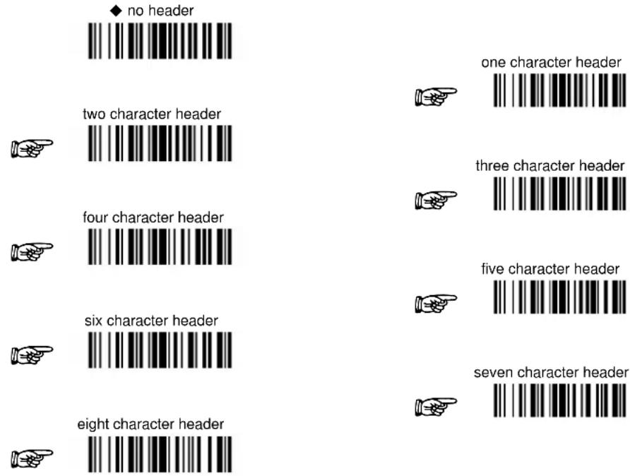
After selecting one of the desired Header codes, read the character(s) from the HEX table. Valid characters are in the range 00-FE. For Wedge and USB-KBD interfaces, it is also possible to read the Special Key(s) on page 49.
Example:

For more details see par. 5.3.1 and par. 5.3.2. See also "Message Formatting" in par. 6.1 and par. 6.2.
TERMINATOR
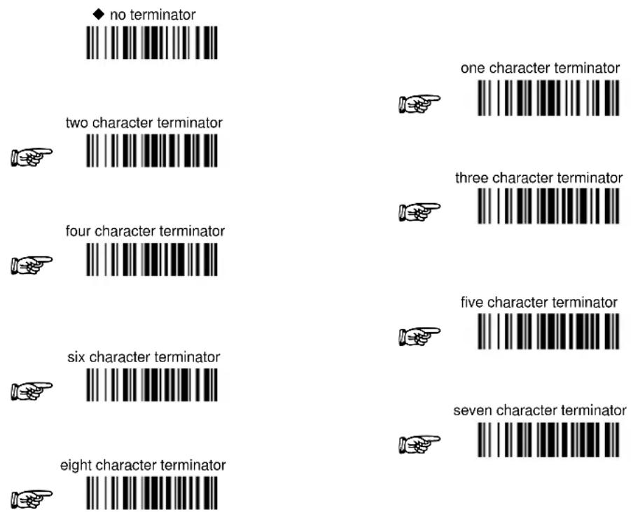
After selecting one of the desired Header codes, read the character(s) from the HEX table. Valid characters are in the range 00-FE. For Wedge and USB-KBD interfaces, it is also possible to read the Special Key(s) on page 49.
Example:

For more details see par. 5.3.1 and par. 5.3.2. See also "Message Formatting" in par. 6.1 and par. 6.2.
OPERATIVE MODE
MODE SELECTION
This feature allows the PowerScan PBT8300-DK to operate in one of two basic operative modes:
- SDIM (Simple Data Input Mode) — data entered, either on the keypad or read via barcode, is transmitted the host once the enter key is pressed, following the formatting rules described in the previous paragraph.
• QTY/CODE (Quantity/Code Mode) — Refer to the next section, QTY/CODE MODE PARAMETERS.
◆ Simple Data Input Mode

Quantity/Code Mode

This command is active only when the scanner is in Simple Data Input Mode. It defines the behavior of the enter key when no data has been previously entered. By default an error sound is generated; it can also be configured to transmit a "null" character.
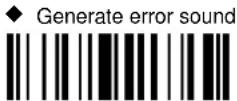

QTY/CODE MODE
When the scanner is in Quantity-Code Mode, the operator is prompted with two data fields named QTY= and CODE= . The normal position of the cursor is in the QTY field; the operator is required to type the quantity on the keypad, then press the "enter key" to move the cursor to the CODE field. Data in the CODE field can either be entered manually from the keypad or read through the scanner.
The pair quantity and code are then transmitted to the host in a single string with configurable header, terminators and separator. Use the commands in the following sections to define the configuration parameters.
QTY FIELD
This feature defines the behavior of the scanner if no data is entered in the QTY field so it is left empty. Options are:
• code is transmitted with default QTY ('1')
• code is transmitted alone (without any quantity information)
• code is discarded and an error beep is generated
◆ Transmit code with default QTY (1)

Discard barcode, generate error beep

Transmit code alone (without any quantity information)

QTY/CODE SEND MODE
This feature defines the rules that will be used to send a QTY/CODE pair:
- code is transmitted with QTY field (and its predefined format) preceding CODE field (and its predefined format)
- code is transmitted with CODE field (and its predefined format) preceding QTY field (and its predefined format)
- code in CODE field is sent out for the number of times defined in the QTY field (when using this option the maximum number of times is '9999');
NOTE: Use "Repeat Timeout" on the next page for to set the timeout for this feature.
◆ QTY precedes CODE

CODE sent out = QTY times

CODE precedes QTY

REPEAT TIMEOUT
Repeat Timeout allows the user to program an optional intercode delay (in msec.) between two codes in a set of codes to be transmitted from scanner to host via Radio interface, when the scanner is in quantity mode.
NOTE: Qty/Code Send Mode must be set to option 2 (code in CODE field is sent out for a QTY number of times). See Qty/Code Send Mode on the previous page).
The number of codes depends on the unit inserted via keypad by the user, to cope with different use cases. A minimum delay of 100 ms will be always present, the delay can be adjusted in 10ms increments.


① Read the above code.
② Select the length of the delay you want to set by scanning two barcodes (01 - 99) from the Hex Numeric table in the back of this manual.
Example: To program Repeat Timeout = 60ms
Read

+
Value
06
=
Time (ms)
60ms
QTY/CODE SEPARATOR
This feature allows the insertion of a separator between QTY/CODE pairs.
◆ Disable – no separator


define QTY/CODE separator

① Read the above code.
② Select the length of the separator you want to insert by scanning a barcode (1 - 8) from the Hex Numeric table in the back of this manual.
③ Define the separator string using a sequence of four hex ascii codes from the table at the back of this manual.
Example: To define QTY/CODE separator = : (colon)

For more information on this feature see "Message Formatting" starting in par. 6.1 and 6.2.
APPEND CODE
This function defines how a scanned barcode interacts with a pre-edited CODE field, or with a string entered by a pre-programmed FUNC KEY.
Options are:
- Barcode data overwrites what is written in the CODE field by keyboard and the code is transmitted;
- Barcode data is appended to any text in the CODE field and the code is transmitted;
- Barcode data is appended to any text in the CODE field but the code IS NOT transmitted. Data is transmitted when the enter key is pressed.
NOTE: Option 2 allows the addition of a footer to the scanned barcode ('just in time formatting').
◆ Overwrite CODE and
transmit

Append to CODE,
don't transmit

Append to CODE and
transmit

5 REFERENCES
5.1 RS-232 Parameters
5.1.1 Handshaking
Hardware handshaking: (RTS/CTS)
The RTS line is activated by the decoder before transmitting a character. Transmission is possible only if the CTS line (controlled by the Host) is active.
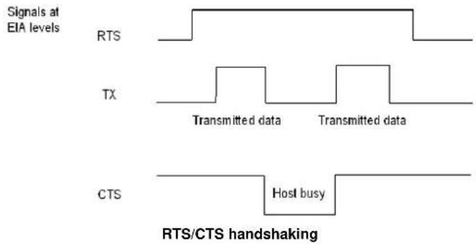
Software handshaking: (XON/XOFF)
During transmission, if the Host sends the XOFF character (13 Hex), the decoder interrupts the transmission with a maximum delay of one character and only resumes when the XON character (11 Hex) is received.
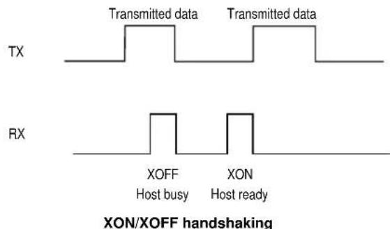
5.2 Pen Parameters
5.2.1 Minimum Output Pulse
This parameter sets the duration of the output pulse corresponding to the narrowest element in the barcode. In this way the code resolution is controlled by the signal sent to the decoder, independently of the physical resolution of the code read.
The shortest pulse (200 s) corresponds to a high-resolution code emulation and therefore a shorter transfer speed to the decoder (for decoders able to work on high resolution codes). Likewise, longer pulses correspond to low-resolution code emulation and therefore a longer transfer time to the decoder.
5.2.2 Conversion to Code 39 and Code 128
PowerScan® BT8300 Series Readers
When using these readers it is possible to choose between converting the decoded codes into either Code 39 format or Code 128 format. It is not possible to disable conversion.
5.2.3 Overflow
This parameter generates a white space before the first bar and after the last bar of the code. The selections are as follows:
narrow = space 10 times the minimum output pulse.
medium = space 20 times the minimum output pulse.
wide = space 30 times the minimum output pulse.
5.2.4 Output and Idle Levels
The following state diagrams describe the different output and idle level combinations for Pen emulation:
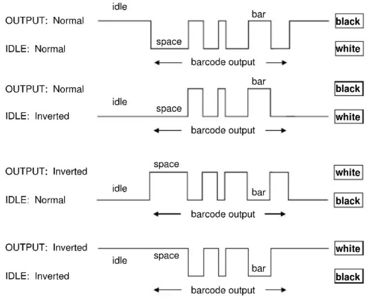
Output and Idle Levels
5.2.5 Inter-Block Delay
For the PEN Emulation interface, data are sent to the Host in fixed size blocks of 20 characters each. The inter-block delay parameter allows setting a delay between each block sent to the Host.
When the PowerScan BT8300 connects with a Bluetooth-Enabled PC, the header and terminator default values will be:
• SPP Profile: no header, terminator CR-LF
• HID Profile: no header, terminator ENTER
5.3 Data Format
For an overview of Message Formatting see Chapter 6.
5.3.1 Header/Terminator Selection
The header/terminator selection is not effected by the reading of the restore default code. In fact, when the PowerScan BT8300 connects with the BC 8030-BT, cradle header and terminator default values depend on the interface selection:
• RS-232: no header, terminator CR-LF
• WEDGE: no header, terminator ENTER
When the PowerScan BT8300 connects with a Bluetooth-Enabled PC, the reader header and terminator default values will be:
• SPP Profile: no header, terminator CR-LF
• HID Profile: no header, terminator ENTER
When the PowerScan BT8300 connects with the BC 8030-BT the default values are usually restored through the reading of RS-232 or WEDGE interface selection code. However, if the PowerScan BT8300 is connected with a Bluetooth-Enabled PC it will NOT reset to default value when switched between Communication Types. In other words, the PowerScan BT8300 can remember the setting of TERMINATOR. See chapter 2.
For the WEDGE interface, the following extended keyboard values can also be configured:
| EXTENDED KEYBOARD TO HEX CONVERSION TABLE | ||||
| IBM AT IBM 3153 APPLE ADB | IBM XT | IBM 31xx, 32xx, 34xx, 37xx | Wyse Digital | |
| HEX | KEY | KEY | KEY | KEY |
| 83 | ENTER | ENTER | FIELD EXIT | RETURN |
| 84 | TAB | TAB | TAB | TAB |
| 85 | F1 | F1 | F1 | F1 |
| 86 | F2 | F2 | F2 | F2 |
| 87 | F3 | F3 | F3 | F3 |
| 88 | F4 | F4 | F4 | F4 |
| 89 | F5 | F5 | F5 | F5 |
| 8A | F6 | F6 | F6 | F6 |
| 8B | F7 | F7 | F7 | F7 |
| 8C | F8 | F8 | F8 | F8 |
| 8D | F9 | F9 | F9 | F9 |
| 8E | F10 | F10 | F10 | F10 |
| 8F | F11 | ESC | F11 | F11 |
| 90 | F12 | BACKSPACE | F12 | F12 |
| 91 | HOME | HOME | ENTER | F13 |
| 92 | END | END | RESET | F14 |
| 93 | PG UP | PG UP | INSERT | F15 |
| 94 | PG DOWN | PG DOWN | DELETE | F16 |
| 95 | ↑ ↑ | FIELD - UP | ||
| 96 | ↓ | ↓ | FIELD + DOWN | |
| 97 | ← | ← | ENTER (Paddle) | LEFT |
| 98 | → | → | RIGHT | |
| 99 | ESC | ESC | ESC | |
| 9A | CTRL (Right) | CTRL (Right) | CTRL (Right) | |
| 9B | Euro | Space | Space | Space |
For all devices using IBM AT (compatible) Wedge or USB-KBD interfaces, all values from 9C to FE send the relative simulated keypress when available or else the relative ALT-Mode sequence. See the Hex to Character Conversion Table in Appendix C.
For all devices using other Wedge interfaces, all values from 9C to FE send the Space character.
5.3.2 Define Special Key Sequence
The Special Key(s) for Wedge IBM AT-PS/2 and USB-KBD interface users can be associated with a sequence of keyboard keys that otherwise could not be selected, i.e. ALT + F6, SHIFT + F1. These Special Keys can be used for:
- Headers/Terminators
- Character Replacement
- Field Adjustment
- Custom Code ID
- Advanced Formatting – Define Field
- Advanced Formatting – Additional Fixed Field
Follow the procedure to define the desired Special Key sequence:
- Read the Enter Configuration code above and select the Special Key to define (one at a time):
Define Special Key 1

Define Special Key 2

Define Special Key 3

Define Special Key 4

Define Special Key 5

- Read only one code to be associated with the special key sequence:

OR
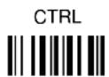
OR

OR
CTRL + SHIFT

OR
ALT + SHIFT

OR
CTRL + ALT

- Select the character to be associated with the Special Key sequence by reading the codes corresponding to the 3 character values from Appendix C. Then, read the Exit and Save Configuration code above to complete the Special Key sequence.
The character values having the ^S and ^A symbols require SHIFT or ALT keys or key combinations in step 2, in particular:
^s = the character is obtained in combination with SHIFT
^A = the character is obtained in combination with ALT
The following character values change according to the keyboard nationality.
| KEYBCHAR | ITA | USA | FR | BE | DE | UK | ES | SW | JP |
| ! | 016^S | 016^S | 04A | 03E | 016^S | 016^S | 016^S | 016^S | 016^S |
| " | 01E^S | 052^S | 026 | 026 | 01E^S | 01E^S | 01E^S | 01E^S | 01E^S |
| # | 052^A | 026^S | 026^A | 026^A | 05D | 05D | 026^A | 026^S | 026^S |
| 025^S | 025^S | 05B | 05B | 025^S | 025^S | 025^S | 025^S | 025^S | |
| % | 02E^S | 02E^S | 052^S | 052^S | 02E^S | 02E^S | 02E^S | 02E^S | 02E^S |
| & | 036^S | 03D^S | 016 | 016 | 036^S | 03D^S | 036^S | 036^S | 036^S |
| ' | 04E | 052 | 025 | 025 | 05D^S | 052 | 04E | 05D | 03D^S |
| ( | 03E^S | 046^S | 02E | 02E | 03E^S | 046^S | 03E^S | 03E^S | 03E^S |
| ) | 046^S | 045^S | 04E | 04E | 046^S | 045^S | 046^S | 046^S | 046^S |
| * | 05B^S | 03E^S | 05D | 05B^S | 05B | 03E^S | 05B^S | 05D^S | 052^S |
| + | 05B | 055^S | 055^S | 04A^S | 05B | 055^S | 05B | 04E | 04C^S |
| , | 041 | 041 | 03A | 03A | 041 | 041 | 041 | 041 | 041 |
| - | 04A | 04E | 036 | 055 | 04A | 04E | 04A | 04A | 04E |
| . | 049 | 049 | 041^S | 041^S | 049 | 049 | 049 | 049 | 049 |
| / | 03D^S | 04A | 049^S | 049^S | 03D^S | 04A | 03D^S | 03D^S | 04A |
| 0 | 045 | 045 | 045^S | 045^S | 045 | 045 | 045 | 045 | 045 |
| 1 | 016 | 016 | 016^S | 016^S | 016 | 016 | 016 | 016 | 016 |
| 2 | 01E 01E | 01E^S | 01E^S | 01E | 01E | 01E | 01E | 01E | |
| 3 | 026 | 026 | 026^S | 026^S | 026 | 026 | 026 | 026 | 026 |
| 4 | 025 | 025 | 025^S | 025^S | 025 | 025 | 025 | 025 | 025 |
| 5 | 02E | 02E | 02E^S | 02E^S | 02E | 02E | 02E | 02E | 02E |
| 6 | 036 | 036 | 036^S | 036^S | 036 | 036 | 036 | 036 | 036 |
| 7 | 03D | 03D | 03D^S | 03D^S | 03D | 03D | 03D | 03D | 03D |
| 8 | 03E | 03E | 03E^S | 03E^S | 03E | 03E | 03E | 03E | 03E |
| 9 | 046 | 046 | 046^S | 046^S | 046 | 046 | 046 | 046 | 046 |
| : | 049^S | 04C^S | 049 | 049 | 049^S | 04C^S | 049^S | 049^S | 052 |
| ; | 041^S | 04C | 041 | 041 | 041^S | 04C | 041^S | 041^S | 04C |
| < | 061 | 041^S | 061 | 061 | 061 | 041^S | 061 | 061 | 041^S |
| = | 045^S | 055 | 055 | 04A | 045^S | 055 | 045^S | 045^S | 04E^S |
| > | 061^S | 049^S | 061^S | 061^S | 061^S | 061^S | 061^S | 061^S | 049^S |
| ? | 04E | 04A^S | 03^A^S | 03A^S | 04^E^S | 04^A^S | 04^E^S | 04^E^S | 04^A^S |
| @ | 04C^A | 01E^S | 045^A | 01E^A | 015^A | 052^S | 01E^A | 01E^A | 054 |
| [ | 054^A | 054 | 02E^A | 054^A | 052^S | 054 | 054^A | 03E^A | 05B |
| \ | 00E | 05D | 03E^A | 061^A | 04C^S | 061 | 00E^A | 04E^A | 051 |
| ] | 05B^A | 05B | 04E^A | 05B^A | 054^S | 05B | 05B^A | 046^A | 05D |
| ^ | 055^S | 036^S | 046^A | 054 | 00E | 036^S | 054^S | 05B^S | 055 |
| _ | 04A^S | 04E^S | 03E | 055 | 04A^S | 04^E^S | 04^A^S | 04^A^S | 051^S |
| '(accent) | - | 00E | 03D^A | 05D^A | 055^S | 00E | 054 | 055^S | 054^S |
| a | 01C | 01C | 015 | 015 | 01C | 01C | 01C | 01C | 01C |
| b | 032 | 032 | 032 | 032 | 032 | 032 | 032 | 032 | 032 |
| c | 021 | 021 | 021 | 021 | 021 | 021 | 021 | 021 | 021 |
| d | 023 | 023 | 023 | 023 | 023 | 023 | 023 | 023 | 023 |
| e | 024 | 024 | 024 | 024 | 024 | 024 | 024 | 024 | 024 |
| f | 02B | 02B | 02B | 02B | 02B | 02B | 02B | 02B | 02B |
| g | 034 | 034 | 034 | 034 | 034 | 034 | 034 | 034 | 034 |
| h | 033 | 033 | 033 | 033 | 033 | 033 | 033 | 033 | 033 |
| i | 043 | 043 | 043 | 043 | 043 | 043 | 043 | 043 | 043 |
| j | 03B | 03B | 03B | 03B | 03B | 03B | 03B | 03B | 03B |
| k | 042 | 042 | 042 | 042 | 042 | 042 | 042 | 042 | 042 |
| l | 04B | 04B | 04B | 04B | 04B | 04B | 04B | 04B | 04B |
| m | 03A | 03A | 04C | 04C | 03A | 03A | 03A | 03A | 03A |
| n | 031 | 031 | 031 | 031 | 031 | 031 | 031 | 031 | 031 |
| o | 044 | 044 | 044 | 044 | 044 | 044 | 044 | 044 | 044 |
| p | 04D | 04D | 04D | 04D | 04D | 04D | 04D | 04D | 04D |
| q | 015 | 015 | 01C | 01C | 015 | 015 | 015 | 015 | 015 |
| r | 02D | 02D | 02D | 02D | 02D | 02D | 02D | 02D | 02D |
| s | 01B | 01B | 01B | 01B | 01B | 01B | 01B | 01B | 01B |
| t | 02C | 02C | 02C | 02C | 02C | 02C | 02C | 02C | 02C |
| u | 03C | 03C | 03C | 03C | 03C | 03C | 03C | 03C | 03C |
| v | 02A | 02A | 02A | 02A | 02A | 02A | 02A | 02A | 02A |
| w | 01D | 01D | 01A | 01A | 01D | 01D | 01D | 01D | 01D |
| x | 022 | 022 | 022 | 022 | 022 | 022 | 022 | 022 | 022 |
| y | 035 | 035 | 035 | 035 | 01A | 035 | 035 | 035 | 035 |
| z | 01A | 01A | 01D | 01D | 035 | 01A | 01A | 01A | 01A |
| - | 054^S | 025^A | 046^A | 052 | 054^S | 052^A | 03D^A | 05B^S | |
| | | 00E^S | 05D^S | 036^A | 016^A | 04C | 061^S | 016^A | 061^A | 06A^S |
| - | 05B^S | 055^A | 045^A | 054 | 05B^S | 05D^A | 045^A | 05D^S | |
| ~ | - | 00E^S | 01E^A | 04A^A | 04E | 05D^S | - | 05B^A | 055^S$ |

NOTE
To use upper case letters, it is necessary to read one of the SHIFT commands from step 2 before the value corresponding to the lower case letters.
The following key values are common to all the keyboard nationalities.
| KEYB KEY | ITA | USA | FR | BE | DE | UK | ES | SW | JP |
| ENTER | 05A | 05A | 05A | 05A | 05A | 05A | 05A | 05A | 05A |
| TAB | 00D | 00D | 00D | 00D | 00D | 00D | 00D | 00D | 00D |
| F1 | 005 | 005 | 005 | 005 | 005 | 005 | 005 | 005 | 005 |
| F2 | 006 | 006 | 006 | 006 | 006 | 006 | 006 | 006 | 006 |
| F3 | 004 | 004 | 004 | 004 | 004 | 004 | 004 | 004 | 004 |
| F4 | 00C | 00C | 00C | 00C | 00C | 00C | 00C | 00C | 00C |
| F5 | 003 | 003 | 003 | 003 | 003 | 003 | 003 | 003 | 003 |
| F6 | 00B | 00B | 00B | 00B | 00B | 00B | 00B | 00B | 00B |
| F7 | 083 | 083 | 083 | 083 | 083 | 083 | 083 | 083 | 083 |
| F8 | 00A | 00A | 00A | 00A | 00A | 00A | 00A | 00A | 00A |
| F9 | 001 | 001 | 001 | 001 | 001 | 001 | 001 | 001 | 001 |
| F10 | 009 | 009 | 009 | 009 | 009 | 009 | 009 | 009 | 009 |
| F11 | 078 | 078 | 078 | 078 | 078 | 078 | 078 | 078 | 078 |
| F12 | 007 | 007 | 007 | 007 | 007 | 007 | 007 | 007 | 007 |
| Home | 26C | 26C | 26C | 26C | 26C | 26C | 26C | 26C | 26C |
| End | 269 | 269 | 269 | 269 | 269 | 269 | 269 | 269 | 269 |
| PG UP | 27D | 27D | 27D | 27D | 27D | 27D | 27D | 27D | 27D |
| PG down | 27A | 27A | 27A | 27A | 27A | 27A | 27A | 27A | 27A |
| Up arrow | 275 | 275 | 275 | 275 | 275 | 275 | 275 | 275 | 275 |
| Down arrow | 272 | 272 | 272 | 272 | 272 | 272 | 272 | 272 | 272 |
| Left arrow | 26B | 26B | 26B | 26B | 26B | 26B | 26B | 26B | 26B |
| Right arrow | 274 | 274 | 274 | 274 | 274 | 274 | 274 | 274 | 274 |
| Esc | 076 | 076 | 076 | 076 | 076 | 076 | 076 | 076 | 076 |
| Ctrl right | 214 | 214 | 214 | 214 | 214 | 214 | 214 | 214 | 214 |
| € | 02E^A | 02E^A | 024^A | 024^A | 024^A | 025^A | 02E^A | 02E^A | - |
| SPACE | 029 | 029 | 029 | 029 | 029 | 029 |

NOTE
If Caps Lock Auto-Recognition is disabled, it is necessary to verify that the keyboard caps lock status matches that on the reader.
EXAMPLES
- Defining Special Key Sequences -
- the following example allows defining Special Key 1 as SHIFT + F5:
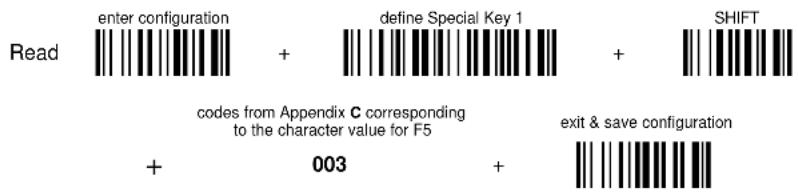
the following example allows defining Special Key 2 as CTRL + S (upper case):
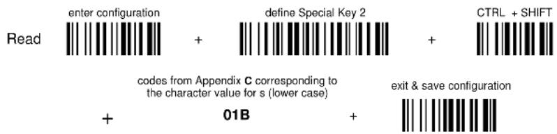
- the following example allows defining Special Key 3 as Alt + F6:
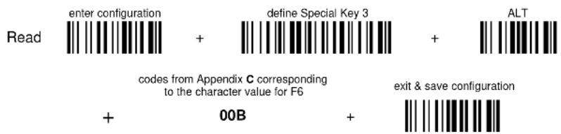
- the following example allows defining Special Key 4 as Alt + Shift + F1:
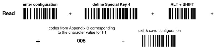
- Integrating Special Keys in Headers/Terminators -
- the following example allows setting Special Key 1 (defined in example 1 above) as terminator:

- the following example allows setting Special Key 2 (defined in example 2 above) as header:

- the following example allows setting Special Key 3 (defined in example 3 above) as header:

- the following example allows setting Special Key 4 (defined in example 4 above) and ENTER character as terminators:

5.3.3 Address Stamping
It is possible to include the reader address in the message sent to the host. The Reader Address Stamping and the Cradle Address Stamping parameters consist of 12 hex characters. For message output format, refer to chapter 6.
5.3.4 Address Delimiter
The Address Delimiter allows a character to be included to separate the reader Address stamping field from the next field in the message. Any character can be included in the hexadecimal range from 00 to FE. For message output format, refer to chapter 6.
5.3.5 Time Stamping Format
The Time Stamping parameter sets the format for hour and date information. It consists of 1 or 2 groups of numbers, each one made up of 6 decimal digits.
For example, setting the Hour/Minutes/Seconds/Month/Day/Year format, the information 17:03:16 on June 12, 2002 will be formatted as 170316061202.
5.3.6 Time Stamping Delimiter
The Time Stamping Delimiter allows a character to be included to separate the Time Stamping field from the next field in the message. Any character can be included in the hexadecimal range from 00 to FE.
5.4 Power Save
5.4.1 Sleep State
When using interfaces other than USB, this mode allows the P in the reader to enter a “Sleep” state for minimum power consumption.
Before entering Sleep mode, the following are verified:
• no commands coming from Host
• no data being transmitted to Host
• Enter Sleep Timeout ended (see par. 5.4.2)
To exit Sleep mode press the trigger.
For BT8300 series readers, sleep state is entered immediately after reading a code and is not configurable. To exit Sleep mode press the trigger.
When using the USB interface, this mode allows the device to manage Selective Suspend conditions generated by the Host Operating System in which optimizing low power consumption (ex. Windows Stand-by). It is possible to exit the Suspend mode either from the Host (ex. moving the mouse during Stand-by) or through the barcode reader. The latter, called Remote Wakeup, makes the device wake up the Host restoring the communication. Remote Wakeup is possible by pressing the trigger.
5.4.2 Enter Sleep Timeout
For readers that have the Sleep state enabled, this timeout determines when the reader will enter this state.
5.5 Reading Parameters
5.5.1 Trigger Signal
This mode determines how the reading phase is controlled when the hardware trigger operating mode is selected:
- trigger active level: the reader goes ON when the trigger is pressed and goes OFF when it is released
- trigger active pulse: the reader goes ON at the first trigger press and goes OFF only at a second press
5.5.2 Trigger Click
When enabled, it activates a "click" sound upon each trigger pressure.
5.5.3 Trigger-Off Timeout
When this timeout is selected, the reader turns OFF automatically after the desired period of time.
5.5.4 Reads per Cycle
In general, a reading cycle corresponds to the ON + OFF times of a device.
The resulting effects of this parameter on code reading depend on other related configuration conditions. Here are the definitions of ON and OFF times.
- For readers using the software trigger parameter (FLASH MODE), a reading cycle corresponds to the flash on + flash off times. Code reading takes place during the flash on time.
- For readers using the hardware trigger parameter, a reading cycle corresponds to a trigger press (ON) + one of the following OFF events:
trigger release (for trigger active level)
a second trigger press (for trigger active pulse)
trigger-off timeout (see par. 5.5.3).
When one read per cycle is selected, the device decodes only one code during the ON period and immediately turns the reader OFF. It is only possible to read another code when the next ON time occurs.
In multiple reads per cycle, the ON period is extended so that the device can continue decoding codes until an OFF event occurs. For software trigger mode, the flash on period is immediately reset after each read and therefore extended. If another code is decoded before the reset flash on period expires, it is again reset and the effect is that the device remains ON, decoding codes until the flash on or timeout period expires.
The Safety Time parameter should be used in this case to avoid unwanted multiple reading of the same code, see par. 5.5.5.
5.5.5 Safety Time
Safety time prevents the device from immediately decoding the same code more than once. Same code consecutive reading can be disabled requiring the reader to be removed from the code (no decoding) for at least 400 ms, or a timeout can be set up to 9.9 seconds before the decoder will accept the same code. Reading is immediate if the code changes.
The safety time parameter is not applicable when reading stacked codes or when setting one read per cycle in hardware trigger operating mode, since these settings require voluntary action by the user.
5.6 Decoding Parameters

CAUTION
These parameters are intended to enhance the decoding capability of the reader for particular applications. Used incorrectly, they can degrade the reading performance or increase the possibility of a decoding error.
5.6.1 Ink-Spread
The ink-spread parameter allows the decoding of codes, which are not perfectly printed because the page texture tends to absorb the ink.
5.6.2 Overflow Control
The overflow control parameter can be disabled when decoding codes printed on small surfaces, which do not allow the use of an overflow space.
This command does not affect code families 2/5, Code 128 and Code 93.
5.6.3 Interdigit Control
The interdigit control parameter verifies the interdigit spacing for code families Code 39 and Codabar.
5.7 Advanced Formatting
5.7.1 Match Conditions
Selecting an Advanced Formatting and specifying a Match restriction (Code Type, Code Length, Predefined Characters) the code will be transmitted according to the order of the defined formats.
For example, defining 2 formats where:
• Format 1: Match Code type = Code128
- Format 2: Match Code length = 15 and Match with Predefined Characters "DATA"
a Code128 "DATA:12345ABCDE" with code length 15 will be formatted following the Format 1.
To send the same code with the Format 2 it is necessary to invert the format order as follows:
- Format 1: Match Code length = 15 and Match with Predefined Characters "DATA"
• Format 2: Match Code type = Code128
5.8 Radio Parameters
5.8.1 Power-Off Timeout
If this command is enabled, after the desired timeout in hours, the PowerScan ^® batteries are disconnected and all power consumption ceases. To restore power, press the trigger once. The reader will now be ready to read codes.
Power-off does not affect configuration parameters.
5.8.2 Beeper Control for Radio Response
For BT8300 series readers, the data entry good read tone normally results in two beeps; the first indicates that the reader has decoded the code; the second indicates whether BC 8030-BT has received the data.
This can be changed according to the following selections:
♦ Normal: both good decode and good receptions are signaled (two beeps).
♦ Only Good Decode: only the first beep indicating a good read is signaled.
♦ Only Good Reception: only the second beep indicating a good reception is signaled.
- Off: Neither good read nor good reception beeps are signaled.
For all configurations, any transmission errors will always be signaled.
5.8.3 Batch Mode
This Operating Mode allows storing read codes in the internal reader memory. The stored codes are transmitted to the base station at a later time according to the type of batch mode selected.
Batch mode can be enabled either manually (normal batch mode) or automatically.
Normal batch mode temporarily suspends radio communication between reader and base station allowing codes to be stored in the reader on a FIFO (first in, first out) basis. This can be useful, for example, if codes must be read from a location where there is no radio network. Upon returning to the system working area, this mode requires reading the Start Normal Batch Transmission barcode to successively transmit the list of stored codes to the base station. The FIFO management assures that the first code read will be the first code to be transmitted to the base station.
The Delete Batch Data barcode allows canceling all barcode data stored in the reader.
Automatic batch mode allows codes to be stored in the reader on a FIFO basis whenever the reader is out of radio range. In this case radio communication is not suspended and transmission is attempted after each code read. If transmission cannot be successfully completed, then the code is added to the list. When the reader returns in range, transmission of the codes to the base station resumes automatically, according to the selected communication protocol, upon simply pressing and releasing the trigger or by successfully reading a new code.
3-KEY MODEL
Each code is listed on the reader display together with its identifying position number and its total number of characters. The three keys under the display have the following function in batch mode:
| Key | Function | |
| ▲ | (left) Key | Scroll up in list |
| ENTER | (center) Key | Delete highlighted code |
| ▼ | (right) Key | Scroll down in list |
The code which has a transmission pending is shown on the display in reverse video, indicating that it cannot be deleted.
16-KEY DK MODEL
If the 'Enable Normal Batch' barcode is read, the FUNCTION KEY1 (F1) is automatically re-configured to toggle between the two different operative modes described in the following paragraphs. The mnemonic label associated to the F1 is Bat (abbreviation of batch).
Operative modes:
- INSERT MODE – this is the common data entry mode and will reflect the operative mode of the system (Quantity Mode, Simple Data Input Mode). All data scanned via barcode or entered on the keyboard will be batched in the persistent memory. Functions keys F2 - F4 maintain their programmed functions.
- SCROLL MODE – in this mode the user can see and can delete previously inserted data. The action of the function keys changes to reflect the different user mode. It will be:
| Function Key | Action | Label |
| F1 | toggles between INSERT MODE and SCROLL MODE | Bat |
| F2 | Scroll up | ↑ |
| F3 | deletes the currently shown data from the batch | Del |
| F4 | Scroll down | ↓ |
After pressing F1 again, the operative mode moves back to "Insert Mode" and the function keys F2-F4 are returned to their originally programmed functions.
Note that the 16-key DK saves the automatic batch in RAM, while the normal batch mode saves to Flash. When entering normal batch mode on the 16-key via programming label, the display shows the message "Flash Erase" to describe the initialization.
5.8.4 See Me
When this feature is enabled, if the PowerScan BT8300 is not used for a few minutes it enters standby mode and its green LED starts blinking in order to signal its location.
5.9 BLUETOOTH PARAMETERS
About Bluetooth Profile Support
A Bluetooth profile is a wireless interface specification for Bluetooth-based communication between devices. In order to use Bluetooth technology, a device must be compatible with the subset of Bluetooth profiles necessary to use the desired services. The profiles provide standards which manufacturers follow to allow devices to use Bluetooth in the intended manner.
With Bluetooth Profile Support, the BC 8030-BT cradle is not required for wireless communication. The PowerScan BT8300 reader communicates directly to the host using Bluetooth technology. The PowerScan BT8300 supports the standard Bluetooth Serial Port Profile (SPP) and HID Profile, which enables the scanner to communicate with other Bluetooth-Enabled devices that support these profiles.
- SERIAL PORT PROFILE – The reader connects to the Bluetooth-Enabled PC and emulates a serial cable to provide a simple substitute for existing RS-232, including the familiar control signals.
- HID PROFILE - The reader connects to the Bluetooth-Enabled PC and emulates a virtual keyboard on the Host.
5.9.1 Communication Type
The PowerScan BT8300 reader can be configured to work with BC 8030-BT cradle, or to use standard Bluetooth profiles based on your Communication Type selection:
- HANDHELD – CRADLE (default): Select this communication type to configure the PowerScan BT8300 reader to work with the BC 8030-BT cradle. The reader must be paired to the cradle and the cradle must connect directly to the Host via multi-interface port.
- SERIAL PORT PROFILE (Master): Select this communication type for Bluetooth Profile Support. The scanner connects to the Bluetooth-Enabled PC and behaves like there's a serial connection. The scanner initiates the connection to the remote device and acts as the Master.
- SERIAL PORT PROFILE (Slave): Select this communication type for Bluetooth Profile Support. The scanner connects to the Bluetooth-Enabled PC and behaves like there's a serial connection. The scanner accepts an incoming connection requested from a remote device and acts as the Slave.
- HID PROFILE: Select this communication type for using Bluetooth Profile Support. The scanner connects to the PC/host via Bluetooth and behaves like a keyboard.
5.9.2 Link By Contact
Link by Contact allows the PowerScan BT8300 reader to connect to the BC 8030-BT cradle when the reader is inserted in the cradle. After scanning Enable Link by Contact, firmly position the reader onto the cradle. The BC 8030-BT cradle will emit a beep and the yellow LED will blink while the cradle is trying to establish the connection. If the connection is successful, four ascending beeps will be emitted and the yellow LED on the cradle will stop blinking; If the connection fails, four descending beeps will be emitted and the yellow LED on the cradle will also stop blinking.
5.9.3 Link By Label
In addition to the procedure shown on page 16, you can create a linking barcode for the BC 8030-BT or Bluetooth-Enable PC to which PowerScan BT8300 can connect. You must know the Bluetooth address of the remote device. Linking bar codes are Code 128 with the following format:
\+QSxxxxxxxxxxxxx\-
\+QHxxxxxxxxxxxxx\-
With
o QS – Scanner is working in Handheld-Cradle or Serial Port Profile (Master).
o QH – Scanner is working in HID profile.
o xxxxxxxxxxxx represents the 12-character Bluetooth address.
Example: Linking Bar Code
If the scanner is configured as SPP Profile (Master) and the remote device to which the scanner can connect has a Bluetooth address of 04:10:19:87:AB:CD, then the linking barcode will be:

5.9.4 Start Up Connect
When the PowerScan BT8300 is in Handheld-Cradle, Serial Port Profile (Master) or HID Profile mode, scanning Enable Start Up Connect will allow the PowerScan BT8300 reader to auto-connect with the paired device when the reader starts up. The paired device is the device to which PowerScan BT8300 reader makes connection successfully in each Communication Type.
The paired device information will automatically be deleted from the PowerScan BT8300 if the reader is restored to factory settings, changes power class, changes communication types or if unpairing is performed.
The green LED on the reader will blink when it tries to make the start up connection. If the connection is successful, four ascending beeps will be emitted and the green LED will stop blinking; Otherwise, four descending beeps will be emitted.
5.9.5 Auto Reconnect
When the PowerScan BT8300 is in Handheld-Cradle, Serial Port Profile (Master) or HID Profile mode, if Auto Reconnect is enabled the reader will automatically attempt to reconnect to a paired device after a disconnection occurs due to the radio losing communication. This can happen if the reader goes out of range with the paired device, or if the paired device powers down. The reader makes the reconnection attempt for the period of time specified by the Reconnect Attempt Interval and Reconnect Attempt Mode settings.
The green LED on the reader will blink as it attempts to make the reconnection. If the connection is successful, four ascending beeps will be emitted and green LED will stop blinking. If the reconnection process fails due to a page timeout, four descending beeps will be emitted.
5.9.6 Reconnect Attempt Interval
When the PowerScan BT8300 reader disconnects as it goes out of range or the remote device is powered down, the BT8300 immediately attempts to reconnect for the time interval specified using Time Reconnect. This time interval can be set to one of the following options:
- 1 minute (default)
- 5 minutes
- 30 minutes
- Indefinitely
5.9.7 Reconnect Attempt Mode
When the time specified by the Reconnect Attempt Interval setting expires without making a connection, it will restart a reconnect attempt either By Trigger or Do Not Attempt, depending on Reconnect Attempt Mode setting.
- By Trigger (default)
- Do Not Attempt
5.9.8 Power Class
The PowerScan BT8300 reader can work with two different types of radio power ranges:
• Class 1 = 100 meters (default)
• Class 2 = 10 meters.
Longer ranges require higher power radios, and consume more battery power for operation.
5.9.9 Security Mode
The PowerScan BT8300 reader supports Bluetooth Authentication and Encryption. Authentication can be requested by either the remote device or the scanner. When Authentication is requested, the scanner uses its programmed PIN code to generate a link key. The scanner stores this link key upon pairing, so you do not have to re-enter the PIN code when moving in and out of range, switching profiles, or switching between devices (e.g., between the cradle and the application). The PowerScan BT8300 reader can be configured to work in one of three security modes that enforce security at different levels:
• Security Mode 1 – Authentication Disable and Encryption Disable
• Security Mode 2 – Encryption Disable and Authentication Enable
• Security Mode 3 – Encryption Enable and Authentication Enable
5.9.10 PIN Code & PIN Length
When the PowerScan BT8300 reader is in Security Mode 2 or Security Mode 3, the PIN code is required to authenticate the connection between the reader and the cradle (in Handheld – Cradle type) or with the Bluetooth-Enabled PC (in Serial Port Profile and HID profile).

NOTE
The mandatory condition for establishing a new connection between a BT reader and a BT cradle or Bluetooth-Enabled PC is that they share the same security configuration and have the same PIN code.
The default PIN code in PowerScan BT8300 reader is 1234. The PIN code can be changed to either of two length options:
• PIN length = 4 (default).
• PIN length = 16
5.9.11 Variable PIN Code
By default PowerScan BT8300 will automatically use a Static PIN Code in response to the authentication connection from the Host. However, some Bluetooth drivers on the Host (such as WIDCOMM and BlueSoleil 8.0.338.0) require a Variable PIN Code. When attempting connection, the application presents a window that includes a PIN Code which is to be input using the PowerScan BT8300. When you hear the beep indicating the reader is waiting for an alphanumeric entry, enter the provided variable PIN Code one of two ways:
- Keypad (PBT8300 16-key DK only): type the PIN Code on the scanner keypad, then tap Enter (←).
- Scanning: read the barcode corresponding with the require PIN Code and ending with Exit and Save configuration label. Use the labels in the HEX/NUMERIC KEYPAD section for alphanumeric entry.
5.9.12 HID Caps Lock Auto-Recognition (IBM AT-Compatible Only)
This option applies only to the HID Profile. When enabled, the case of the data is preserved regardless of the state of the caps lock key on the Bluetooth – Enabled Host.
5.9.13 HID Alt Mode
The HID ALT Mode selection allows barcodes sent to the PC to be interpreted correctly independently from the HID Country Code used. An HID Country Code does not need to be selected.

NOTE
Ensure that the Num Lock key on the keyboard is ON when in HID ALT mode is enabled.
5.9.14 HID Interchar Delay
This parameter sets the delay, in milliseconds, between emulated keystrokes in HID Profile. The allowed delay can be set from 0 milliseconds (disabled) up to 99 milliseconds.
5.9.15 HID Send Unknown ASCII Character
Unknown characters are characters the host does not recognize. When Disable HID Send ASCII Unknown character is selected, all barcode data is sent except for unknown characters, and an error beep will sound. When Enable HID Send ASCII Unknown character is selected, an unknown character will be sent as a SPACE.
5.10 Display Parameters (Some BT8300 Models only)
5.10.1 Display Mode
The user can control the reader display behavior according to the following selections:
Normal mode: When a barcode is read with the reader:
• The code is sent to the Host.
- The reader display is not cleared. Therefore if any previous data was displayed on the reader screen it remains.
• There is no Local Echo to the reader display.
Clear Display After Decode mode: When a barcode is read with the reader:
• The code is sent to the Host.
- The reader display is cleared. Therefore if any previous data was displayed on the reader screen it is cancelled and the screen remains blank.
• There is no Local Echo of the code to the reader display.
Local Echo mode: When a barcode is read with the reader:
- The code is sent to the Host.
• The reader display is cleared.
• The code is also sent to the reader display (Local Echo). - The cursor is positioned after the last printed character on the reader display.
Host messages sent to the reader are always written to the reader display.
5.11 Configuration Editing Commands
The following commands carry out their specific function and then exit the configuration environment.
Command Description
 | Restore PowerScan® reader default configuration (see the relative Quick Reference Guide for default settings) |
 | Transmit the PowerScan® BT8300 software release. |
 | Transmit PowerScan® reader configuration in ASCII format.This command is not effective with Pen emulation interface. |
 | Restore BC 8030-BT default configuration (see the relative Quick Reference Guide for default settings) |
 | Transmit the BC 8030-BT Software release. |
 | Transmit BC 8030-BT configuration in ASCII format. This command is not effective with Pen Emulation interface. |
5.12 Custom Default Configuration
Read the following code to set the reader user-defined configuration as custom default configuration:
Save User-defined Configuration as Custom Default

Read the following code whenever you need to restore the custom default configuration:
Restore Custom Default Configuration

5.13 Code Type Recognition
This procedure allows the reader to enter a particular state during which it reads and transmits to the Host information about the family type of codes unknown to the user (with the exception of MSI, Code 49 and Code 16k code types). It is also possible to read and transmit configuration strings without interpreting them. All codes are read ignoring the check digit.
Follow the given procedure:
① Read the following code to enter the code type recognition mode:

code type recognition

② Read existing codes whose family type you need to check.
③ Read the following code to return to the reader's normal functioning:
exit code type recognition mode

5.14 Configuration Copying Commands
5.14.1 Copy PowerScan™ BT8300 Series
Procedure:
① Using the slave reader and its BC 8030-BT cradle, follow the initialization procedure in this manual or from the Quick Reference Guide.
② With the master PowerScan™ BT8300 (correctly configured reader), read the Copy Configuration barcode below. Then place it onto an BC 8030-BT cradle within 10 seconds. The reader will beep indicating the configuration has been copied.
The configuration will be simultaneously sent over the RS-232 interface of the BC 8030-BT. If this causes undesired effects disconnect the RS-232 cable between the PC and BC 8030-BT during this process.
Copy Configuration

③ With the slave PowerScan™ BT8300, read the Get Configuration barcode below. Then place it onto the same BC 8030-BT cradle used in the step above. The slave reader's address will not be changed.
Get Configuration

The configuration will be copied from the master to the slave PowerScan™ BT8300. The slave PowerScan™ BT8300 signals the end of the procedure with a series of beeps. It is now ready to be used with its own BC 8030-BT cradle.
④ Repeat the procedure above to configure other slave readers. The BC 8030BT can continue to configure slave readers until it receives another command or data.
5.14.2 Copy BC 8030-BT
Procedure:
① Using the slave reader and its BC 8030-BT cradle, read the Restore Default barcode, set the radio address, and then read the RS-232 interface barcode in this manual or from the Quick Reference Guide.
② Connect the master BC 8030-BT and the slave BC 8030-BT (cradle to be configured) together through two RS-232 serial interface cables and external power supply. Accessory cables and power supply are available from your Datalogic distributor to provide this connection.
RS-232 Cables: CAB471 & CAB472
Power Supply: PG12
③ Read the Configuration Copy barcode below with a reader. Then place it onto the master BC 8030-BT cradle.
Copy Configuration

The configuration will be copied from the master BC 8030-BT to the slave BC 8030-BT. The reader signals the end of the procedure with a series of beeps.
④ Repeat the procedure above to configure other slave cradles.
NOTE: The master BC 8030-BT can be configured for any interface.
5.15 Default Parameters for POS Terminals
The default values of the RS-232 and Data Format parameters for POS terminals are listed in the following table:
| NIXDORF Mode A | FUJITSU | ICL Mode | |
| RS-232 Group | |||
| Baud Rate | 9600 | 9600 | 9600 |
| Parity | Odd | None | Even |
| Data Bits 8 8 8 | |||
| Stop Bits | 1 | 1 | 1 |
| Handshaking | Hardware (RTS/CTS) | None | RTS always ON |
| Inter-Character Delay | Disabled | Disabled | Disabled |
| Serial Trigger Lock | Disabled | Disabled | Disabled |
| Data Format Group | |||
| Code Identifier | Custom | Custom | Custom |
| Header | No Header | No Header | No Header |
| Terminator | CR | CR | CR |
| Field Adjustment | Disabled | Disabled | Disabled |
| Code Length TX | Not Transmitted | Not Transmitted | Not Transmitted |
| Character Replacement | Disabled | Disabled | Disabled |
| Address Stamping | Disabled | Disabled | Disabled |
| Address Delimiter | Disabled | Disabled | Disabled |
| Time Stamping | Disabled | Disabled | Disabled |
| Time Delimiter | Disabled | Disabled | Disabled |
The table below lists all the Code Identifiers available for the POS terminals:
| CODE | NIXDORF Mode A | FUJITSU | ICL Mode |
| UPC-A | A0 | A | A |
| UPC-E | C0 | E | E |
| EAN-8 | B | FF | FF |
| EAN-13 | A | F | F |
| Code 39 | M | None | C [code length] |
| Codabar | N | None | N [code length] |
| Code 128 | K | None | L [code length] |
| Interleaved 2 of 5 | I | None | I [code length] |
| Code 93 | L | None | None |
| Industrial 2 of 5 | H | None | H [code length] |
| UCC/EAN 128 | P | None | L [code length] |
| MSI | O | None | None |
| GS1 DATABARTM | E | None | None |
| Other | None | None | None |
5.16 Firmware Upgrade
Device firmware upgrades can be performed from your PC through a serial connection (RS-232). Download the free configuration software tool Aladdin from the Datalogic web site: http://www.scanning.datalogic.com and install it by clicking on the setup file.
Procedure:
- Connect the device to the PC via USB cable or serial connection (RS-232).
- Launch Aladdin on your PC. From the menu, select Tools > firmware upgrade.
- Read the code below and position the reader onto the cradle:

Prepare device for firmware upgrade
- Press the cradle button. The device will automatically reset.
- Proceed with the firmware upgrade (see the Aladdin on-line help for details).

CAUTION
Do not interrupt firmware upgrade downloading for any reason.
5.17 16-Key PowerScan BT8300-DK Display and Keypad Parameters
5.17.1 16-key Keyboard Data Format Enable/Disable
The default Data Format is configured in the scanner system, and valid for all PowerScan models. They will be applied to the read barcode by the scanner. This is the typical method of configuration for all BT8300 models, including the BT8300-DK. Therefore, the Keyboard Data Format on the DK model does not overwrite or substitute for the default Data Format, but is potentially additional.
On the BT8300-DK the following configuration scenarios are available:
Keyboard Data Format= Disabled
- Scanner Data Header/Terminator = not null
Formatting is applied identically to a label read or data input from the keyboard (as programmed with Scanner Data Header/Terminator on page 146). Keypad Data Header/Terminator will be ignored in this case.
Keyboard Data Format= Enabled
- Scanner Data Header/Terminator = not null
Scanner Data Header/Terminator formatting is applied only to data received from a scanned barcode label (see page 146).
Keypad Data Header/Terminator formatting is applied only to data input from the keypad (see page 148).
In all the above cases Scanner Code ID and Scanner Code Length are not affected.
NOTE: This configuration item is part of the scanner configuration but is applied to the whole system. The configuration does not overwrite the default Data Format, but is additional.
5.17.2 Scanner Code ID
The default Data Format is valid for all BT8300 models. Code Identifier and Code len TX (on pages 71,76 in this manual) are also valid for DK models. The item configuration is part of the cradle configuration and is applied to the scanner system.
Optionally, the DK 16-key scanner can be set for:
- Scanner Code ID
- Scanner Code Len TX
(with the same optional values as for standard formatting)
Differently from the other DK formatting, these two configuration items have priority over the corresponding standard formatting, and hide or substitute for them.
As a result the BT8300-DK can have the following configuration scenarios:
Scanner Code ID = Disable
The settings from the standard Code ID on page 71 will be used (if programmed).
Scanner Code ID = any different value from Disable (option 1,2,3 – Datalogic standard, AIM standard, or custom)
Use the specific DK Scanner Code ID instead of the standard Code ID. DK Scanner Code ID will be applied and will take priority over any standard Code ID settings, even if programmed.
5.17.3 Scanner Code Length
The behavior of Scanner Code Length is similar to that described above for Scanner Code ID.
As a result the BT8300-DK can have the following configuration scenarios:
Scanner Code Length = Disable
The settings from the standard Code Len TX on page 76 will be used (if programmed).
Scanner Code Length = any different value from Disable (variable digit format, fixed digit format)
Use the specific DK Scanner Code Length instead of the standard Code Len TX. Scanner Code Length will be applied and will take priority over any standard Code Len TX settings, even if programmed.
NOTE: Both of these configuration items are part of the scanner configuration but are applied to the whole system. The configuration item overwrites the default Data Format.
6 MESSAGE FORMATTING
6.1 Standard Message Formatting
The system always provides scanner to host data communication using the following message formatting:
Output Message from standard PowerScan® BT8300 Towards Host
[Header] [Scanner_Addr] [Scanner_Addr_delimiter] [Cradle_Addr] [Cradle_Addr_delimiter]
[Time stamp] [Ts_delimiter] [Code ID] [Code Length] CODE [Terminator]
[Items in square brackets are optional.]
For PowerScan ^® BT8300 models with display, if the RS-232 interface is selected for communication between the Host and the BC 8030-BT cradle, then the following additional communications between Host and Scanner can occur:
- The Host can send messages to any associated scanner, to control the Scanner's display, LEDs and beeper.
• The Scanner can send up to 3 user-defined characters using the command keys on the Scanner.
6.2 Advanced Message Formatting
The table below describes conventions and definitions used in the examples on the following page. In both the table and in the examples, formatting items valid only for the reader are shown in italics. The prefix C means the item is programmed from the BC 8030-BT cradle, and the prefix R means it is programmed from the PowerScan BT8300 reader.
| [R Header] | It can be:○ [ Reader Data Header]or○ [ Keypad Data Header]depending on whether data is read from a barcode or typed on the keypad. |
| [R Terminator] | It can be:○ [Reader Data Terminator]or○ [ Keypad Data Terminator]depending on whether data is read from a barcode or typed on the keypad. |
| [Code ID] | The optional Code ID formatting. It can be programmed:• From the BC 8030-BT cradle, represented in the following as[C ID]• from the PowerScan BT8300 reader, represented in the following as[R ID] |
| [Code len] | The optional Code len formatting. It can be programmed:• from BC 8030-BT cradle, represented in the following as[C len]• from the PowerScan BT8300 reader, represented in the following as[R len] |
[C Header] [Reader_Addr] [Reader_Addr delimiter] [Cradle_Addr] [Cradle_Addr_delimiter] [Time Stamp] [Time Stamp Delimiter] [R Header] [Code ID] [Ccode len] CODE [R Terminator] [C Terminator]
Code ID, Code Length and Code can be different content in the reader. These features can be programmed with Reader Data Header/Terminator on page 121, or Keypad Data Header/Terminator on page 121.
Field code ID and Code length may also be programmed in the reader:
[C Header] [Reader Addr] [Reader Addr delimiter] [Cradle Addr] [Cradle Addr delimiter] [Time Stamp] [Time Stamp Delimiter] [R Header] [C ID] [C len] CODE [R Term] [C Term]
[C Header] [Reader Addr] [Reader Addr delimiter] [Cradle Addr] [Cradle Addr delimiter] [Time Stamp] [Time Stamp Delimiter] [R Header] [R ID] [R len] CODE [R Term] [C Term]
NOTE: in case of double formatting for [Code ID] [Ccode len], only one of these is included in message formatting. Specific Data Format [R ID] [R len] takes priority over general Data Format.
The code field [CODE] as additional formatting in the 16-key model, when the device is programmed in Qty/Code mode.
6.3 Messages from SCANNER Command Keys
6.3.1 PowerScan BT8300 keypad
The PowerScan ^® BT8300 series scanners with display have 3 command keys that can each be associated with a character to send to the host.
By pressing the keys on the scanner, the associated character with its relative message formatting is sent to the Host. For example, keys can be used to select items from a menu sent to the scanner display by the application program.
The general format is:
[Header] [Reader_Addr] [Reader_Addr_delimiter] ] [Cradle_Addr] [Cradle_Addr_delimiter] [Time stamp] [Ts_delimiter] [Code ID] [Code Length] KeyID [Terminator]
[Items in square brackets are optional.]
The messages are handled by the system as if they were barcodes, that's why KeyID can have so many fields appended to it. If in your application there is some chance of reading a 1-char barcode identical to KeyID, the way you can distinguish between the two is to enable the Code ID: The KeyID is the only 1-character long EAN 8 code.
The default characters associated with each key (KeyID) are shown in the following table:
| Default Key Identifiers | ||
| Key | KeyID | |
| ▲ | (left) Key | '<' |
| ENTER | (center) Key | =' |
| ▼ | (right) Key | '>' |
PowerScan BT8300-DK 16-key keypad
The 16-key keypad contains 4 programmable functions keys (see Function Key Programming on page 141 for more information). In addition, there is a Shift key which is used to access the alphabetic part of the keyboard, and an Enter key used to confirm “manually” input data.
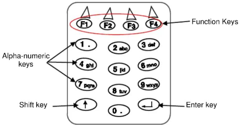
flowchart
graph TD
    A["Alpha-numeric keys"] --> B["1 ."]
    A --> C["4 ghl"]
    A --> D["7 pqrs"]
    E["Shift key"] --> F["↑"]
    G["Enter key"] --> H["0 ."]
    I["F1"] --> J["2 abc"]
    K["F2"] --> L["3 daf"]
    M["F3"] --> N["5 lkd"]
    O["F4"] --> P["6 mno"]
    Q["F5"] --> R["8 tuv"]
    S["F6"] --> T["9 wxyz"]
The 16-key keypad is organized like a cell phone, with multi-tap access to alpha characters on numeric keys. Press the keys once, twice, or more to cycle through the alpha letters and symbols until the desired character appears in the display.
The following table shows the key press options for each alphanumeric key:
| Key | First Keypress | Second Keypress | Third Keypress | Fourth Keypress |
| 1 | . | |||
| 2 | a | b | c | |
| 3 | d | e | f | |
| 4 | g | h | i | |
| 5 | j | k | l | |
| 6 | m | n | o | |
| 7 | p | q | r | s |
| 8 | t | u | v | |
| 9 | w | x | y | z |
7 TECHNICAL FEATURES
7.1 PowerScan ^® BT8300
| Electrical and General Features | ||
| Battery Type | 2150 Li-Ion battery pack | |
| Recharge Time | max. 4 hours with external power supplymax 10 hours with Host power | |
| Operating autonomy(continuous reading) | 50,000 reads (typical) | |
| Display(Only available with some models) | LCD 4 lines x 16 charsProgrammable font and backlight | |
| Indicators | Good Read LED (green)Good Read Spot (green), Beeper | |
| Laser Features | BT8300 | BT8300 AR |
| Light Source | VLD between 630~680 nm | |
| Scan Rate 35 ± 5 scans/sec | ||
| Power (max) in mW | 0.9 mW | 1.3 mW |
| Scan Angle | 42° | 13.5° ± 0.7 |
| PCS minimum(Datalogic Test Chart) | 15% 25% | |
| Maximum Resolution | 0.076 mm (3 mils) | 0.19 mm (7.5 mils) |
| Reading Field Width | see reading diagrams (par. 7.5) | |
| Laser Safety Class | CLASS 2 EN 60825-1 / CDRH | |
| Bluetooth Features | ||
| Protocol | Bluetooth 2.0; Class 1 or Class 2 configurable; SPP (Serial Port Profile)or HID (Human Interface Device) profile | |
| Radio Frequency | 2.40 to 2.48 GHz | |
| Environmental Features | ||
| Working Temperature | -20° to +50 °C / -4° to +122 °F | |
| Storage Temperature | -20° to +70 °C / -4° to +158 °F | |
| Humidity | 90% non condensing | |
| Drop resistance (on concrete)IEC 68-2-32 Test ED | 2 m | |
| Protection Class | IP65 (IP64 for models with display) | |
| Mechanical Features | ||
| Weight (with batteries) | about 400 g (14.10 oz) | |
| Dimensions | 212 x 109 x 71 mm (8.34 x 4.49 x 2.79 in) | |
| Material | Polycarbonate molded with rubber | |
| Keyboard | BT8300: no keyboard or displayBT8300-D: 3 key keypad and displayBT8300-DK: 16 key keypad and display | |
7.2 BC 8030-BT
| BC 8030-BT | ||
| Electrical and General Features | ||
| Supply Voltage | ||
| External Power | 10 to 30 VDC | |
| Host Power | 5 VDC ±10% | |
| Power Consumption | ||
| External Power | max. 10 W (charging)* | |
| Host Power | max. 500 mA (charging) | |
| Indicators | Ext. Power /Data yellow LEDHost Power/Data yellow LEDReader batt. state green/red LED | |
| Recharge Time | ||
| External Power | max. 4 hours with 2150 mAh Li-Ion battery | |
| Host Power | max. 10 hours with 2150 mAh Li-Ion battery | |
| Host Interfaces | ||
| RS-232 | 300 to 38400 baud | |
| WEDGE | IBM AT or PS/2, XT, PC Notebook, IBM SURE1, IBM 3153, 31xx, 32xx, 34xx, 37xx terminals, Wyse terminals, Digital VT terminals, Apple ADB Bus supported | |
| PEN Emulation | Selectable minimum pulse from 200 □S to 1.2 mS | |
| USB | USB-KBD, USB-KBD-ALT-MODE, USB-KBD APPLE, USB-COM, USB-IBM-Table Top, USB-IBM-Hand Held | |
| Environmental Features | ||
| Working Temperature | -20° to +50 °C / -4° to +122 °F** | |
| Storage Temperature | -20° to +70 C / -4° to +158° F | |
| Humidity | 90% non condensing | |
| Protection | IP40 | |
| Mechanical Features | ||
| Weight without cable | about 380 g / 13.4 oz | |
| Dimensions (without antenna) | 204 x 108 x 95 mm / 9.44 x 4.25 x 3.74 in | |
| Material | ABS | |
* Having a switching regulator inside, the BC 8030-BT draws the same power, regardless of the supply voltage. i.e. as the input voltage increases the current drawn decreases.
** Batteries must be charged at a temperature ranging from 0° to +40 °C / +32° to +104 °F.
7.3 System CONFIGURATION
| System Configuration BC 8030-BT | |
| Max number of devices per base station | 4 |
7.4 Status Indicators
The scanner has two indicator LEDs and a Beeper. The BC-8000 and C-8000 cradles have four LED indicators (three for BC-8010 model) and a Beeper. They signal several operating conditions, which are described in the tables below.
$$ \mathbf {H} = \text { high tone } $$
$$ \mathbf {L} = \text { low tone } $$
POWERSCAN® BT8300 READER START-UP
| Beeper ^1 | Meaning |
| LLLL Parameters loaded correctly | |
| HHH long tones | Parameter loading error, reading or writing error in the non volatile memory |
| HLHL Hardware error in EEPROM | |
POWERSCAN® BT8300 READER CONFIGURATION
| Beeper ^1 Meaning | |
| H H H H | Correct entry or exit from Configuration mode |
| L Good read of a command | |
| L L L Command read error | |
POWERSCAN® BT8300 READER DATA ENTRY
| Beeper1 | LED Good | Read Spot | Meaning |
| one beep2 | ON | ON | Correct read of a code in normal mode |
| H L long | TX error | between Power | Scan® BT8300 and BC-8030-BT |
| H long | ON | ON | Successful advanced format concatenation |
| H H H | Timeout expired – operation not completed | ||
| H H long | Error in advanced data formatting | ||
| OFF | OFF | Ready to read a code |
POWERSCAN® BT8300 POWER
| Beeper LED Meaning | ||
| 10 short H | 10 short blinks | Low Battery |
| HML Power off | ||
H = high tone
M = medium tone
L = low tone
BC 8030-BT POWER/COMMUNICATION
| Aux LED Host | LED | Meaning |
| Yellow Yellow | ||
| OFF | OFF | Device off |
| ON Power | applied through an | external power supply |
| ON | Power applied through the Host | |
| Flashing | Flashing | Transmission over the Host port |
BC 8030-BT CHARGE STATUS
| Reader LED | Meaning | ||
| Red | Green | Beeper | |
| OFF | OFF | No reader battery inserted | |
| ON | Reader battery in charge | ||
| ON | single beep | Reader battery completely charged | |
| Flashing orange | Reader battery fault | ||
| Alternating red/green | repetitive beep | Charging out of temperature range, over-current or over-voltage conditions | |
| Alternating red/green every 30 seconds | beep every 30 seconds | Reader not correctly inserted onto cradle, no charging takes place | |
| Spare LED (not for BC-8010) | Meaning | ||
| Red | Green | Beeper | |
| OFF | OFF | No Spare battery inserted in the SBS-3000 slot | |
| ON | Spare battery in charge | ||
| ON | Spare battery completely charged | ||
| Flashing orange | Spare battery fault | ||
| Alternating red/green | repetitive beep | Charging out of temperature range, over-current or over-voltage conditions | |
| Alternating red/green every 30 seconds | beep every 30 seconds | Spare battery not correctly inserted into SBS-3000, no charging takes place | |
7.5 Reading Diagrams
Reading Distance
PowerScan™ BT8300
| mil | Typical reading distance with good quality codes |
| 5 | 2.1 - 13.3 cm / 0.8 - 5.2 in |
| 7,5 | 3.5 - 24.2 cm / 1.4 - 9.5 in |
| 10 | 2.9 - 42.8 cm / 1.1 - 16.8 in |
| 13 | 2.3 - 55.1 cm / 0.9 - 21.7 in |
| 20 | 6.3 - 78.5 cm / 2.5 - 30.9 in |
| 40 | 2.5 - 97.8 cm / 1.0 - 38.5 in |
PowerScan™ BT8300 AR
| mil | Typical reading distance with good quality codes |
| 7,5 | 18 - 50 cm / 7.0 - 19.7 in |
| 10 | 18 - 85 cm / 7.0 - 33.5 in |
| 15 | 15 - 165 cm / 5.9 - 65.0 in |
| 20 | 12 - 210 cm / 4.7 - 82,7 in |
| 40 | 18 - 375 cm / 7.0 - 147.6 in |
| 55 | 25 - 485 cm / 9.8 in - 15.9 ft |
| 100(refl. Paper) | 1.5 - 12.5 m / 4.9 ft - 41.0 ft |
A HOST CONFIGURATION STRINGS
In this section we provide a description of how to modify the device configuration using serial strings sent from the Host.
This method requires the RS-232 interface.
The device configuration can be changed by receiving commands from the Host through the serial interface. When this method is used, the programming sequence format is the following:
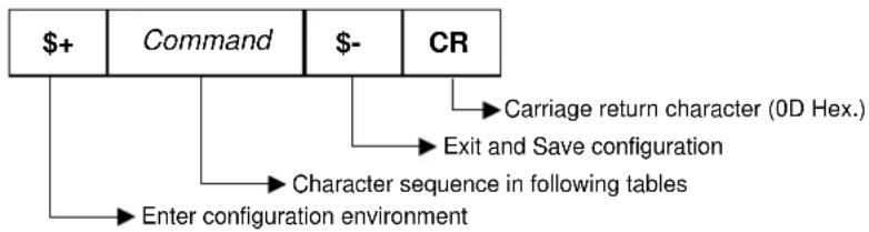
flowchart
graph TD
    A["$+"] --> B["Command"]
    B --> C["$-"]
    C --> D["CR"]
    D --> E["Carriage return character (0D Hex.)"]
    D --> F["Exit and Save configuration"]
    D --> G["Character sequence in following tables"]
    G --> H["Enter configuration environment"]
Example:
Multiple command programming sequence:
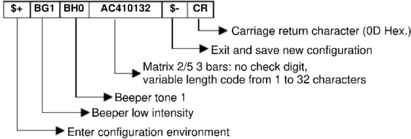
flowchart
graph TD
    A["$+"] --> B["BG1"]
    B --> C["BH0"]
    C --> D["AC410132"]
    D --> E["$-"]
    E --> F["CR"]
    F --> G["Carriage return character (0D Hex.)"]
    F --> H["Exit and save new configuration"]
    H --> I["Matrix 2/5 3 bars: no check digit, variable length code from 1 to 32 characters"]
    I --> J["Beeper tone 1"]
    J --> K["Beeper low intensity"]
    K --> L["Enter configuration environment"]
Each configuration parameter setting removes the condition previously active for that parameter.

NOTE
The device buffer can contain about 400 characters. If your programming string goes over this value, you must split it into separate groups and send each group after a delay of at least 3 seconds to give the reader time to empty the buffer and interpret the commands.
SERIAL CONFIGURATION STRINGS
| SPECIAL CONFIGURATION COMMANDS | |
| DESCRIPTION | STRING |
| Enter Configuration | + |
| Exit and Save Configuration | - |
| Restore Default | +* |
| Transmit Software Release (not for PEN emulation) | +! |
| Transmit Device Configuration in ASCII (not for PEN emulation) | +& |
| Set Custom Default | +0 |
| Restore Custom Default | +1 |
These commands do not require \$-.
| INTERFACE SELECTION | |||
| DESCRIPTION | STRING | ||
| RS-232 | Standard | CP0 | |
| ICL Mode | CM0 | ||
| Fujitsu | CM1 | ||
| Nixdorf Mode A | CM2EC0 | ||
| WEDGE | for IBM AT | CP500 | |
| for IBM Terminals: 31xx, 32xx, 34xx, 37xx; make-break keyboard | CP501 | ||
| for IBM Terminals: 31xx, 32xx, 34xx, 37xx; make-only keyboard | CP502 | ||
| Keyboard Type for IBM Terminals 31xx, 32xx, 34xx, 37xx | typewriter | FK0 | |
| advanced | FK1 | ||
| for IBM XT | CP503 | ||
| for IBM Terminal 3153 | CP504 | ||
| for IBM PC Notebook | CP505 | ||
| for IBM SURE1 | CP506 | ||
| for IBM AT - ALT mode | CP507 | ||
| for IBM PC Notebook - ALT mode | CP508 | ||
| for Wyse Terminal - ANSI Keyboard | CP509 | ||
| for Wyse Terminal - PC Keyboard | CP510 | ||
| for Wyse Terminal - ASCII Keyboard | CP511 | ||
| for Wyse Terminal - VT220 style Keyboard | CP514 | ||
| for Digital Terminals VT2xx/3xx/4xx | CP512 | ||
| PEN EMULATION | CP6 | ||
| USB | USB-KBD | UA03 | |
| USB-KBD-ALT-MODE | UA04 | ||
| USB-KBD-APPLE | UA05 | ||
| USB-COM | UA02 | ||
| USB-IBM-Table Top | UA00 | ||
| USB-IBM-Hand Held | UA01 | ||
| RS-232 | ||
| DESCRIPTION | STRING | |
| Baud Rate | 300 | CD1 |
| 600 | CD2 | |
| 1200 | CD3 | |
| 2400 | CD4 | |
| 4800 | CD5 | |
| 9600 | CD6 | |
| 19200 | CD7 | |
| 38400 | CD8 | |
| Parity | none | CC0 |
| even | CC1 | |
| odd | CC2 | |
| Data Bits | 7 | CA0 |
| 8 | CA1 | |
| 9 | CA2 | |
| Stop Bits | 1 | CB0 |
| 2 | CB1 | |
| Handshaking | disable | CE0 |
| RTS/CTS | CE1 | |
| XON/XOFF | CE2 | |
| RTS always On | CE3 | |
| Inter-character Delay (ms) | CK00 - CK99 | |
| Serial Trigger Lock | disable | CR0 |
| enable and select characters | CR1ab | |
a = Hex values representing an ASCII character from 00 to FE enabling the device trigger.
b = HEX values representing an ASCII character from 00 to FE inhibiting the device trigger.
| USB | ||
| DESCRIPTION | STRING | |
| USB-COM | ||
| Handshaking | disable | CE0 |
| RTS/CTS | CE1 | |
| XON/XOFF | CE2 | |
| RTS always ON | CE3 | |
| Inter-character Delay (ms) | CK00 - CK99 | |
| Serial Trigger Lock | disable | CR0 |
| enable | CR1ab | |
| USB-KBD | ||
| Keyboard Nationality (not for USB-KBD-ALT-MODE) | Belgian | FJ7 |
| English (UK) | FJ4 | |
| French | FJ2 | |
| German | FJ3 | |
| Italian | FJ1 | |
| Spanish | FJ6 | |
| Swedish | FJ5 | |
| USA | FJ0 | |
| Keyboard Nationality (IBM AT compatible only) | Japanese | FJ8 |
| Russian (Latin) | FJ9 | |
| Russian (Cyrillic) | FJA | |
| Hungarian | FJB | |
| Slovenian, Croatian, Serbian (Latin) | FJC | |
| Romanian | FJD | |
| Czech Republic | FJE | |
| Delays | Inter-Character (ms) | CK00 - CK99 |
| Inter-Code (s) | FG00 - FG99 | |
| USB Keyboard Speed | normal | UT10 |
| fast | UT01 | |
a = Hex values representing an ASCII character from 00 to FE enabling the device trigger.
b = HEX values representing an ASCII character from 00 to FE inhibiting the device trigger.
| WEDGE | ||
| DESCRIPTION | STRING | |
| Keyboard Nationality | Belgian | FJ7 |
| English (UK) | FJ4 | |
| French | FJ2 | |
| German | FJ3 | |
| Italian | FJ1 | |
| Spanish | FJ6 | |
| Swedish | FJ5 | |
| USA | FJ0 | |
| Keyboard Nationality(IBM AT compatible only) | Japanese | FJ8 |
| Russian (Latin) | FJ9 | |
| Russian (Cyrillic) | FJA | |
| Hungarian | FJB | |
| Slovenian, Croatian, Serbian (Latin) | FJC | |
| Romanian | FJD | |
| Czech Republic | FJE | |
| Caps Lock | caps Lock ON | FE1 |
| caps Lock OFF | FE0 | |
| Caps Lock Auto-Recognition(IBM AT compatible only) | disable | FP0 |
| enable | FP1 | |
| Num Lock | toggle num lock | FL1 |
| num lock unchanged | FL0 | |
| Delays | Inter-Character (ms) | CK00 - CK99 |
| Inter-Code (s) | FG00 - FG99 | |
| Control Character Emulation | Ctrl + Shift + Key | FO0 |
| Ctrl + Key | FO1 | |
| PEN | ||
| DESCRIPTION | STRING | |
| Operating Mode | interpret (does not require + or-) | ] |
| transparent (does not require+ or -) | [ | |
| Minimum Output Pulse | 200 μs | DG0 |
| 400 μs | DG1 | |
| 600 μs | DG2 | |
| 800 μs | DG3 | |
| 1 ms | DG4 | |
| 1.2 ms | DG5 | |
| Conversion to Code 39 and Code 128 | disable conversion to Code 39 (D series only) | DA0 |
| enable conversion to Code 39 | DA1 | |
| enable conversion to Code 128 (M series only) | DA2 | |
| Output Level | normal | DD0 |
| inverted | DD1 | |
| Idle Level | normal | DE0 |
| inverted | DE1 | |
| Overflow | narrow overflow | DH0 |
| medium overflow | DH1 | |
| wide overflow | DH2 | |
| Inter-block Delay (100 ms) | CK00-CK99 | |
| DATA FORMAT (NOT FOR PEN EMULATION INTERFACES) | ||
| DESCRIPTION | STRING | |
| Cradle Code Identifier | disable | EB0 |
| Datalogic standard | EB1 | |
| AIM standard | EB2 | |
| custom | EB3 | |
| Reader Code Identifier | disable | EZ0 |
| Datalogic standard | EZ1 | |
| AIM standard | EZ2 | |
| custom | EZ3 | |
| Custom Code Identifier | EHabc | |
| Cradle Header | no header | EA00 |
| one character | EA01x | |
| two characters | EA02xx | |
| three characters | EA03xxx | |
| four characters | EA04xxxxx | |
| five characters | EA05xxxxx | |
| six characters | EA06xxxxxx | |
| seven characters | EA07xxxxxxxxx | |
| eight characters | EA08xxxxxxxxx | |
| Reader Header | no header | EU00 |
| one character | EU01x | |
| two characters | EU02xx | |
| three characters | EU03xxx | |
| four characters | EU04xxxxx | |
| five characters | EU05xxxxx | |
| six characters | EU06xxxxxx | |
| seven characters | EU07xxxxxxxxx | |
| eight characters | EU08xxxxxxxxx | |
| Cradle Terminator | no terminator | EA10 |
| one character | EA11x | |
| two characters | EA12xx | |
| three characters | EA13xxx | |
| four characters | EA14xxxxx | |
| five characters | EA15xxxxx | |
| six characters | EA16xxxxxx | |
| seven characters | EA17xxxxxxxxx | |
| eight characters | EA18xxxxxxxxx | |
| Reader Terminator | no terminator | EU10 |
| one character | EU11x | |
| two characters | EU12xx | |
| three characters | EU13xxx | |
| four characters | EU14xxxxx | |
| five characters | EU15xxxxx | |
| six characters | EU16xxxxxx | |
| seven characters | EU17xxxxxxxxx | |
| eight characters | EU18xxxxxxxxx | |
| Special Keys | Key 1 | 9C |
| Key 2 | 9D | |
| Key 3 | 9E | |
| Key 4 | 9F | |
| Key 5 | A0 | |
| Field Adjustment | disable | EF0 |
| right addition | EFa0d | |
| left addition | EFa1d | |
| right deletion | EFa2d | |
| left deletion | EFa3d | |
| Field Adjustment Character | EGe | |
| Cradle Code Length | disable | EE0 |
| variable digit format | EE1 | |
| fixed digit format | EE2 | |
| Reader Code Length | disable | EX0 |
| variable digit format | EX1 | |
| fixed digit format | EX2 | |
| Character Replacement | disable character replacement | EO0 |
| first character replacement | EO1afg | |
| second character replacement | EO2afg | |
| third character replacement | EO3afg | |
| Address Stamping | disable reader address stamping | QA0 |
| enable reader address stamping | QA1 | |
| disable cradle address stamping | Qa0 | |
| enable cradle address stamping | Qa1 | |
| Address Delimiter enable reader address delimiter | disable reader address delimiter | QF0 |
| delimiter and select character | QF1h | |
| disable cradle address delimiter | Qf0 | |
| enable cradle address delimiter and select character | Qf1h | |
| Time Stamping | disable | IL0 |
| hour/minutes/seconds/month/day/year | IL1 | |
| hour/minutes/seconds/day/month/year | IL2 | |
| hour/minutes/seconds | IL3 | |
| month/day/year | IL4 | |
| day/month/year | IL5 | |
| Time Stamping Delimiter | disable time stamping delimiter | IMS0 |
| enable time stamping delimiter | IMS1 | |
| select time stamping delimiter character | IM1h | |
a = ASCII character.
b, c, x = HEX values representing an ASCII character.
a = ASCII character of the DATALOGIC STANDARD Code Identifier from the table on page 42.
b = Hex value of the first Custom Code Identifier character from 00 to FD;
FF = disable Code Identifier
c = Hex value of the second Custom Code Identifier character from 00 to FD;
FF = disable second character of Custom Code Identifier
d = a number in the range 01-32 from the Hex/Numeric Table
e = Hex value from 00 to FE
f = Hex value of the character to be replaced from 00 to FE
g = Hex value of the new character to insert from 00 to FE
FF = replace with no new character (remove character)
h = a HEX value in the range from 00 - FE representing the ASCII character.
x = Hex value from 00 to FE
| POWER SAVE | ||
| DESCRIPTION | STRING | |
| Sleep State(only for D8330 series) | disable | BQ0 |
| enable | BQ1 | |
| Enter Sleep Timeout (100 ms) | BR00-BR99 | |
| READING PARAMETERS | ||
| DESCRIPTION | STRING | |
| Trigger Type | software trigger | BK0 |
| hardware trigger | BK1 | |
| always on | BK3 | |
| Trigger Signal | trigger active level | BA0 |
| trigger active pulse | BA1 | |
| Trigger Click | disable | Bc0 |
| enable | Bc1 | |
| Trigger-off Timeout (s) | BD00 - BD99 | |
| FLASH ON (100 ms) | BB001 - BB099 | |
| FLASH OFF (100 ms) | BB101 - BB199 | |
| Reads per Cycle | one read | BC0 |
| multiple reads | BC1 | |
| Safety Time (100 ms) | BE00 - BE99 | |
| Beeper Intensity | very low intensity | BG0 |
| low intensity | BG1 | |
| medium intensity | BG2 | |
| high intensity | BG3 | |
| Beeper Tone | tone 1 | BH0 |
| tone 2 | BH1 | |
| tone 3 | BH2 | |
| tone 4 | BH3 | |
| Beeper Type | monotone | BJ0 |
| bitonal | BJ1 | |
| Beeper Length | long | BI0 |
| short | BI1 | |
| Good Read Spot Duration | disable | BV0 |
| short | BV1 | |
| medium | BV2 | |
| long | BV3 | |
| Aiming System | disabled | Bj0 |
| enabled | Bj1 | |
| Cradle Beeper Intensity | disable | JI0 |
| low intensity | JI1 | |
| medium intensity | JI2 | |
| high intensity | JI3 | |
| DECODING PARAMETERS | ||
| DESCRIPTION | STRING | |
| Ink-spread | disable | AX0 |
| enable | AX1 | |
| Overflow Control | disable | AW1 |
| enable | AW0 | |
| Interdigit Control | disable | AV0 |
| enable | AV1 | |
| Puzzle SolverTM | disable | AU0 |
| enable | AU1 | |
| Decoding Safety | one read | ED0 |
| two reads | ED1 | |
| three reads | ED2 | |
| four reads | ED3 | |
| CODE SELECTION | |||
| DESCRIPTION | STRING | ||
| DISABLE ALL FAMILY CODES | AZ0 | ||
| EAN/UPC | disable EAN/UPC family | AA0 | |
| EAN 8/EAN 13/UPC A/UPC E | without ADD ON | AA1 | |
| with ADD ON | AA5 | ||
| with and without ADD ON | AA8 | ||
| EAN 8/EAN 13 | without ADD ON | AA3 | |
| with ADD ON 2 ONLY | AAK | ||
| with ADD ON 5 ONLY | AAL | ||
| with ADD ON 2 AND 5 | AA6 | ||
| UPC A/UPC E | without ADD ON | AA4 | |
| with ADD ON 2 ONLY | AAM | ||
| with ADD ON 5 ONLY | AAN | ||
| with ADD ON 2 AND 5 | AA7 | ||
| EAN/UPC with and without Add On no Autodiscrimination | AA8Ad0 | ||
| EAN/UPC Autodiscrimination Add On by Prefix | AA8Ad1 | ||
| Select Prefixes | cancel all selections | ET0 | |
| 378/379 | ET1378ET2379 | ||
| 414/419 | 434/439 | ET3434ET4439 | |
| ET5414ET6419 | |||
| 977 | ET7977 | ||
| 978 | ET8978 | ||
| 979 | ET9979 | ||
| EAN 8 check digit transmission | disable | AAG0 | |
| enable | AAG1 | ||
| EAN 13 check digit transmission | disable | AAH0 | |
| enable | AAH1 | ||
| UPC A check digit transmission | disable | AAI0 | |
| enable | AAI1 | ||
| UPC E check digit transmission | disable | AAJ0 | |
| enable | AAJ1 | ||
| conversions | UPC E to UPC A | AAA | |
| UPC E to EAN 13 | AAB | ||
| UPC A to EAN 13 | AAC | ||
| EAN 8 to EAN 13 | AAD | ||
| ISBN Conversion codes | enable ISBN | AP1 | |
| enable ISSN | AP2 | ||
| enable ISBN and ISSN | AP3 | ||
| disable ISBN and ISSN | AP0 | ||
| Code 39 | disable Code 39 family | AB0 | |
| Standard | no check digit control | AB11 | |
| check digit control and transmission | AB12 | ||
| check digit control without transmission | AB13 | ||
| Full ASCII | no check digit control | AB21 | |
| check digit control and transmission | AB22 | ||
| check digit control without transmission | AB23 | ||
| CODE SELECTION (continued) | |||
| DESCRIPTION | STRING | ||
| CIP 39 | AB3 | ||
| Code 32 | AB4 | ||
| code length | AB*xxxx | ||
| 2/5 | disable Code 2/5 family | AC0 | |
| Interleaved 2/5 | no check digit control | AC11xxxxx | |
| check digit control and transmission | AC12xxxxx | ||
| check digit control without transmission | AC13xxxxx | ||
| Normal 2/5 5 bars | no check digit control | AC21xxxxx | |
| check digit control and transmission | AC22xxxxx | ||
| check digit control without transmission | AC23xxxxx | ||
| Industrial 2/5 (IATA) | no check digit control | AC31xxxxx | |
| check digit control and transmission | AC32xxxxx | ||
| check digit control without transmission | AC33xxxxx | ||
| Matrix 2/5 3 bars | no check digit control | AC41xxxxx | |
| check digit control and transmission | AC42xxxxx | ||
| check digit control without transmission | AC43xxxxx | ||
| CIP/HR | AC5 | ||
| Codabar no start/start/stop | disable Codabar family | AD0 | |
| Standard | no start/stop character equality control nor transmission | AD111 | |
| stop character equality | lity control but transmission | AD112 | |
| start/stop character equality control but no transmission | AD121 | ||
| character equality | control and transmission | AD122 | |
| ABC Codabar | no start/stop character equality control but transmission | AD212 | |
| Codabar ABC forced concatenation | AD232 | ||
| code length | AD*xxxxx | ||
| character case in transmission | lower case | ||
| upper case | |||
| Code 128 | disable Code 128 family | AI0 | |
| enable Code 128 - control without transmission of check digit | AI11 | ||
| enable EAN 128 - control without transmission of check digit | AI21 | ||
| Transmit GS before Code ISBT 128 | disable enable enable ISBT 128 | EQ0 | |
| EQ1 | |||
| AI31 | |||
| code length | AILxxxxx | ||
| Code 93 | disable Code 93 family | AK0 | |
| enable Code 93 - control without transmission of check digit | AK1 | ||
xxxx = ASCII numbers that define the code length where:
- First 2 digits = minimum acceptable code length.
- Second 2 digits = maximum acceptable code length.
The minimum code length must always be less than or equal to the maximum.
The maximum code length for all codes is 99 characters:
Examples:
0132 = variable length from 1 to 32 digits in the code.
1010 = 10 digit code length only.
| CODE SELECTION (continued) | ||
| DESCRIPTION | STRING | |
| MSI | disable the family | AE0 |
| no check | AE1 | |
| MOD10 no tx | AE2 | |
| MOD10 with tx | AE3 | |
| MOD11-MOD10 no tx | AE4 | |
| MOD11-MOD10 with tx | AE5 | |
| MOD10-MOD10 no tx | AE6 | |
| MOD10-MOD10 with tx | AE7 | |
| Code 11 | disable the family | AG0 |
| no check | AG1 | |
| Type C with tx | AG21 | |
| Type C no tx | AG22 | |
| Type K with tx | AG31 | |
| Type K no tx | AG32 | |
| Type C and K with tx | AG41 | |
| Type C and K no tx | AG42 | |
| Code 16K | disable | AJ0 |
| enable | AJ1 | |
| Code 49 | disable | AM0 |
| enable | AM1 | |
| GS1 DataBarTMCodes disable GS1 Data | disable the family | AQ0 |
| aBar Expanded Linear and Stacked | AQ10 | |
| enable GS1 DataBar Expanded Linear and Stacked | AQ11 | |
| disable GS1 DataBar Limited | AQ20 | |
| enable GS1 DataBar Limited | AQ21 | |
| disable GS1 DataBar Linear and Stacked | AQ30 | |
| enable GS1 DataBar Linear and Stacked | AQ31 | |
xxxx = ASCII numbers that define the code length where:
- First 2 digits = minimum acceptable code length.
- Second 2 digits = maximum acceptable code length.
The minimum code length must always be less than or equal to the maximum.
The maximum code length for all codes is 99 characters:
Examples:
0132 = variable length from 1 to 32 digits in the code.
1010 = 10 digit code length only.
| RADIO PARAMETERS | ||
| DESCRIPTION | STRING | |
| Power-Off Timeout | RP00RP99 | |
| Beeper Control For Radio Response | normal | BF0 |
| only good decode | BF1 | |
| only good reception | BF2 | |
| off | BF3 | |
| Batch Mode | disable | BZ0 |
| Enable normal batch | BZ1 | |
| Enable automatic batch | BZ2 | |
| See Me | disable | Bk0 |
| Enable | Bk1 | |
| BLUETOOTH PARAMETERS | ||
| DESCRIPTION | STRING | |
| Communication Type | Handheld - Cradle | QT2 |
| Serial Port Profile (Master) | QT0 | |
| Serial Port Profile (Slave) | QT1 | |
| HID Profile | QT3 | |
| Bluetooth Friendly Name | Set Friendly Name | QNbb |
| Link by Contact | Enable | QD1 |
| Disable | QD0 | |
| Start Up Connect | Enable | QW1 |
| Disable | QW0 | |
| Auto Reconnect | Enable | QU1 |
| Disable | QU0 | |
| Reconnect Attempt Interval | 1 minute | QY0 |
| 5 minutes | QY1 | |
| 30 minutes | QY2 | |
| Indefinitely | QY3 | |
| Reconnect Attempt Mode | By Trigger | QV1 |
| Do Not Attempt | QV0 | |
| Power Class | Reader Power Class 1 | QZ0 |
| Reader Power Class 2 | QZ1 | |
| Cradle Power Class 1 | QZ0 | |
| Cradle Power Class 2 | QZ1 | |
| Cradle Security mode | Security mode 1 | Qb0 |
| Security mode 2 | Qb1 | |
| Security mode 3 | Qb2 | |
| Reader Security mode | Security mode 1 | QB0 |
| Security mode 2 | QB1 | |
| Security mode 3 | QB2 | |
| PIN Length | Reader PIN Length = 4 | QP0 |
| Reader PIN Length = 16 | QP1 | |
| Cradle PIN Length = 4 | Qp0 | |
| Cradle PIN Length = 16 | Qp1 | |
| PIN Code | Set Reader PIN Code 4 | QXhhhh |
| Set Reader PIN Code 16 | QXhhhhhhhhhhhhhhhh | |
| Set Cradle PIN Code 4 | Qxhhhh | |
| Set Cradle PIN Code 16 | Qxhhhhhhhhhhhhhhhh | |
| Variable PIN Code | Static PIN Code | QQ1 |
| Variable PIN Code | QQ0 | |
| Discoverable Mode | Enable | QE1 |
| Disable | QE0 | |
b= Read 2 numbers in the range 00-26 to define the Length + Read HEX characters to define Friendly Name
a= Read 12 characters to represent Host Bluetooth Address
h = Read HEX numbers to assign 4 or 16 PIN Code
| BLUETOOTH PARAMETERS (continued) | ||
| DESCRIPTION | STRING | |
| HID Country Code | Country Code = U.S | QI00 |
| Country Code = Italy | QI01 | |
| Country Code = France | QI02 | |
| Country Code = Germany | QI03 | |
| Country Code = Britain | QI04 | |
| Country Code = Sweden | QI05 | |
| Country Code = Spain | QI06 | |
| Country Code = Belgium | QI07 | |
| Country Code = Japanese 106-key | QI08 | |
| Country Code = Poland | QI09 | |
| Country Code = Hungary | QI0A | |
| Country Code = Croatia | QI0B | |
| Country Code = Romania | QI0C | |
| Country Code = Czech Republic | QI0D | |
| Country Code = Slovakia | QI0E | |
| Country Code = Denmark | QI0F | |
| Country Code = Norway | QI10 | |
| Country Code = Portugal | QI11 | |
| Country Code = Switzerland | QI12 | |
| HID Caps Lock State | Caps Lock OFF | QL0 |
| Caps Lock ON | QL1 | |
| HID Caps Lock Auto-Recognition(IBM AT compatible only)○ | Enable | QM1 |
| Disable | QM0 | |
| HID Alt Mode | Enable | QK0 |
| Disable | QK1 | |
| HID Interchar Delay (ms) | HID Interchar Delay | QJ00-QJ99 |
| HID Send Unknown ASCII Char | Disable | QO0 |
| Enable | QO1 | |
d = Read 2 numbers from the table where:
00 = DELAY disable
01-99 = DELAY from 1 to 99 milliseconds
| DISPLAY PARAMETERS | ||
| DESCRIPTION | STRING | |
| Date | IAddmmyy | |
| Time | IBhhmm | |
| Contrast | lighter | IC0 |
| darker | IC1 | |
| Font Size | small | ID0 |
| medium | ID1 | |
| large | ID2 | |
| Backlight | off | IE0 |
| on | IE1 | |
| Display-Off Timeout | IFa | |
| Display Mode | normal | IG0 |
| local echo | IG1 | |
| clear display after decode | IG2 | |
| Keypad | disabled keys | IK0 |
| enable and select KeyID characters | IK1bbb | |
ddmmyy = numbers from the Hex/Numeric Table representing day, month, year
hhmm = numbers from the Hex/Numeric Table representing hour, minutes
a = a number from the Hex/Numeric Table
b = HEX values representing an ASCII character
a = a number in the range 00-99 (sec.) from the Hex/Numeric Table
00 = Timeout disabled (always on).
b = 3 Hex values from 00 to FE representing the left, center and right keys.
FF = KeyID disabled.
| DISPLAY PARAMETERS 16-Keys | ||
| DESCRIPTION | STRING | |
| Keypad Enable | Keypad Disabled | ISO |
| Keypad Enabled | IS1 | |
| Interkey Timeout | 0.5 sec. | BI0 |
| 1 sec. | BI1 | |
| 1.5 sec. | BI2 | |
| 2 sec. | BI3 | |
| Key Press Sound | Disabled | IQ0 |
| Enabled | IQ1 | |
| Function Key Programming | INcx | |
| String Table | no terminator | IPc0 |
| one character | IPC1b | |
| two characters | Ipc2bb | |
| three characters | Ipc3bbb | |
| four characters | Ipc4bbbb | |
| five characters | Ipc5bbbb | |
| six characters | Ipc6bbbbbbb | |
| seven characters | Ipc7bbbbbbb | |
| eight characters | Ipc8bbbbbbbb | |
| nine characters | Ipc9bbbbbbbb | |
| Ten characters | IpcAbbbbbbbbb | |
| b | ||
| Function Key Label | IOcbbbb | |
| Lower Case | Disable Lower Case | Bn0 |
| Enabled Lower Case | Bn1 | |
| Shift Key Programming | Shift Key Normal Mode | Bo0 |
| Shift Key Function 5 | Bo1 | |
| Echo | Full Keypad Echo | Bq0 |
| No Echo Function Key | Bq1 | |
| No Echo on any Key | Bq2 | |
| Date | IAddmmyy | |
| Time | IBhhmm | |
| Contrast | lighter | IC0 |
| darker | IC1 | |
| Display-Off Timeout | IFtt | |
| Last Code Shown Timeout | IRtt | |
| Backlight | All Backlighting Disabled | IE0 |
| Display enabled, Keyboard disabled | IE1 | |
| Display disabled, Keyboard enabled | IE2 | |
| Display disabled, Keyboard disabled | IE3 | |
| Screen Refresh | Enabled | Bp0 |
| Disabled | Bp1 | |
| Keyboard Data Format Enable | Disabled | Be0 |
| Enabled | Be1 | |
| Time Stamping Mode | Data from both barcode and keyboard | Bf0 |
| Data only from barcode | Bf1 | |
| Data only from keyboard | Bf2 | |
| DISPLAY PARAMETERS 16-Keys (Continued) | ||
| Keypad Data Header | no header | EV00 |
| one character | EV01b | |
| two characters | EV02bb | |
| three characters | EV03bbb | |
| four characters | EV04bbbb | |
| five characters | EV05bbbb | |
| six characters | EV06bbbbbbb | |
| seven characters | EV07bbbbbbbb | |
| eight characters | EV08bbbbbbbb | |
| Keypad Data Terminator | no terminator | EV10 |
| one character | EV11b | |
| two characters | EV12bb | |
| three characters | EV13bbb | |
| four characters | EV14bbbb | |
| five characters | EV15bbbb | |
| six characters | EV16bbbbbbb | |
| seven characters | EV17bbbbbbbb | |
| eight characters | EV18bbbbbbbb | |
| Operative Mode Selection | Simple Data Input Mode | Bd0 |
| Quantity/Code Mode | Bd1 | |
| Enter Key Configuration | Generate error sound | Br0 |
| Send null char | Br1 | |
| QTY Field | Transmit code with dafault QTY | Bh0 |
| Transmit code alone | Bh1 | |
| Discard barcode, generate error beep | Bh2 | |
| QTY/CODE send mode | QTY precedes CODE | Bg0 |
| CODE precedes QTY | Bg1 | |
| Code sent out | Bg2 | |
| Repeat Timeout | Bitt | |
| QTY/CODE separator | no terminator | EW0 |
| one character | EW1b | |
| two characters | EW2bb | |
| three characters | EW3bbb | |
| four characters | EW4bbbb | |
| five characters | EW5bbbb | |
| six characters | EW6bbbbbbb | |
| seven characters | EW7bbbbbbb | |
| eight characters | EW8bbbbbbbb | |
| Append Code | Overwrite CODE and transmit | Bm0 |
| Append to CODE and transmit | Bm1 | |
| Append to code, don't transmit | Bm2 | |
ddmmyy = numbers from the Hex/Numeric Table representing day, month, year
hhmm = numbers from the Hex/Numeric Table representing hour, minutes
a = a number from the Hex/Numeric Table
b = HEX values representing an ASCII character
c = a number from the Hex/Numeric Table in range [1..5] representing the Function Key identifier
x = a number from the Hex/Numeric Table in range [0..A] representing the CMD_ID identifier
t = a number in the range 00-99 (sec.) from the Hex/Numeric Table
00 = Timeout disabled (always on).
b = 3 Hex values from 00 to FE representing the left, centre and right keys.
FF = KeyID disabled.
EAN 13 with 2 ADD ON

UPC A with 2 ADD ON

UPC E with 2 ADD ON

2/5 Industrial

2/5 matrix 3 bars

EAN 13

UPC E

EAN 8 with 5 ADD ON

EAN 13 with 5 ADD ON

UPC A with 5 ADD ON

UPC E with 5 ADD ON

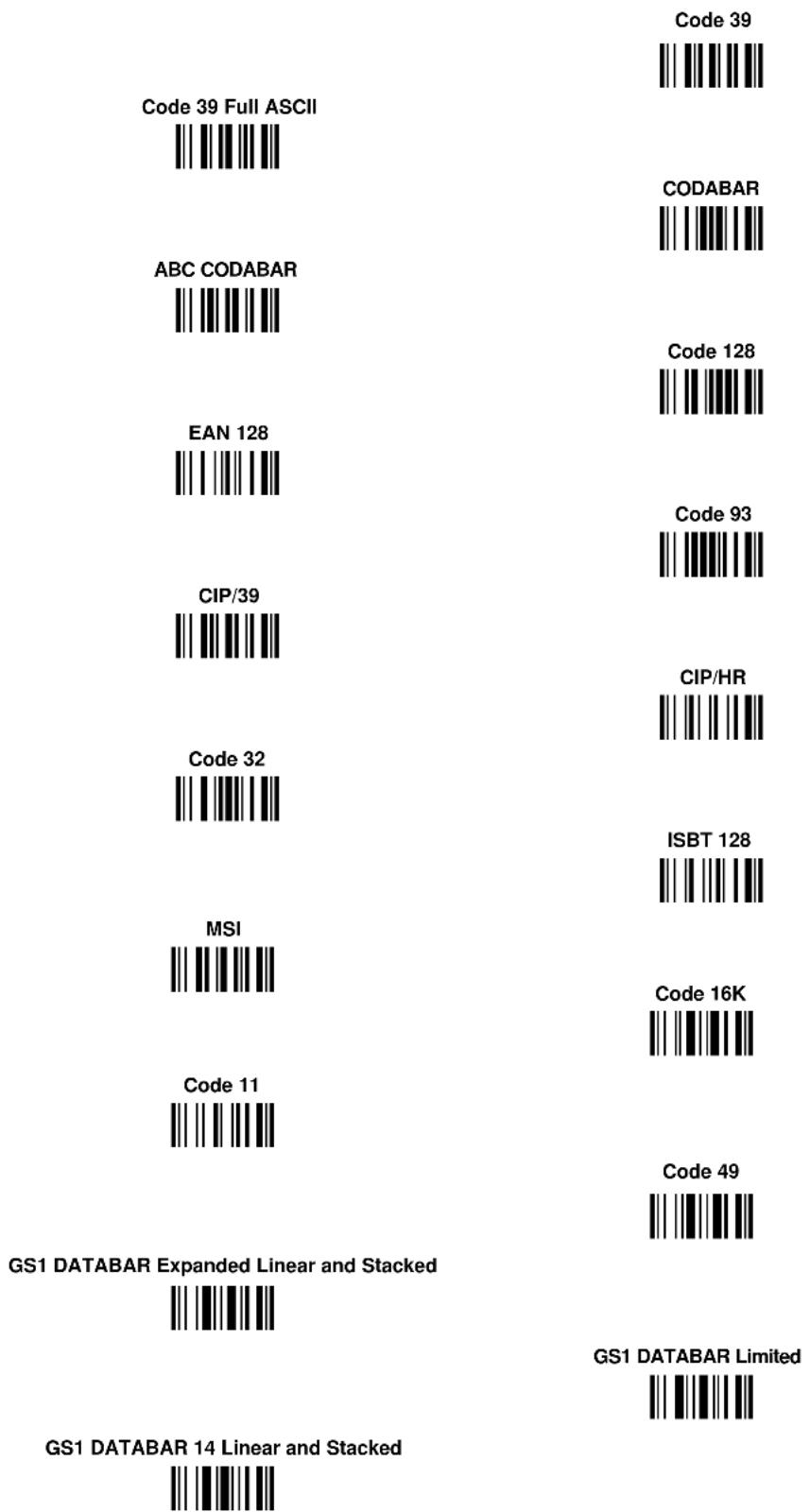
bar
| Code | Value | | --- | --- | | Code 39 Full ASCII | | | CODABAR | | | ABC CODABAR | | | Code 128 | | | EAN 128 | | | Code 93 | | | CIP/39 | | | CIP/HR | | | Code 32 | | | ISBT 128 | | | MSI | | | Code 16K | | | Code 11 | | | Code 49 | | | GS1 DATABAR Expanded Linear and Stacked | | | GS1 DATABAR Limited | | | GS1 DATABAR 14 Linear and Stacked | |C HEX AND NUMERIC TABLE
| CHARACTER TO HEX CONVERSION TABLE | |||||
| char | hex | char | hex | char | hex |
| NUL | 00 | * | 2A | U | 55 |
| SOH | 01 | + | 2B | V | 56 |
| STX | 02 | , | 2C | W | 57 |
| ETX | 03 | - | 2D | X | 58 |
| EOT | 04 | . | 2E | Y | 59 |
| ENQ | 05 | / | 2F | Z | 5A |
| ACK | 06 | 0 | 30 | [ | 5B |
| BEL | 07 | 1 | 31 | \ | 5C |
| BS | 08 | 2 | 32 | ] | 5D |
| HT | 09 | 3 | 33 | ^ | 5E |
| LF | 0A | 4 | 34 | 5F | |
| VT | 0B | 5 | 35 | 60 | |
| FF | 0C | 6 | 36 | a | 61 |
| CR | 0D | 7 | 37 | b | 62 |
| SO | 0E | 8 | 38 | c | 63 |
| SI | 0F | 9 | 39 | d | 64 |
| DLE | 10 | : | 3A | e | 65 |
| DC1 | 11 | ; | 3B | f | 66 |
| DC2 | 12 | < | 3C | g | 67 |
| DC3 | 13 | = | 3D | h | 68 |
| DC4 | 14 | > | 3E | i | 69 |
| NAK | 15 | ? | 3F | j | 6A |
| SYN | 16 | @ | 40 | k | 6B |
| ETB | 17 | A | 41 | l | 6C |
| CAN | 18 | B | 42 | m | 6D |
| EM | 19 | C | 43 | n | 6E |
| SUB | 1A | D | 44 | o | 6F |
| ESC | 1B | E | 45 | p | 70 |
| FS | 1C | F | 46 | q | 71 |
| GS | 1D | G | 47 | r | 72 |
| RS | 1E | H | 48 | s | 73 |
| US | 1F | I | 49 | t | 74 |
| SPACE | 20 | J | 4A | u | 75 |
| ! | 21 | K | 4B | v | 76 |
| " | 22 | L | 4C | w | 77 |
| # | 23 | M | 4D | x | 78 |
| $ | 24 | N | 4E | y | 79 |
| % | 25 | O | 4F | z | 7A |
| & | 26 | P | 50 | { | 7B |
| ' | 27 | Q | 51 | | | 7C |
| ( | 28 | R | 52 | } | 7D |
| ) | 29 | S | 53 | ~ | 7E |
| T | 54 | DEL | 7F | ||
| CHARACTER TO HEX CONVERSION TABLE | |||||
| char | hex | char | hex | char | hex |
| € | 80 | a | AA | Õ | D5 |
| || | 81 | « | AB | Õ | D6 |
| , | 82 | ¬ | AC | × | D7 |
| ENTER | 83 | - | AD | ∅ | D8 |
| TAB | 84 | ® | AE | Ü | D9 |
| F1 | 85 | - | AF | Ú | DA |
| F2 | 86 | ° | B0 | Û | DB |
| F3 | 87 | ± | B1 | Ü | DC |
| F4 | 88 | 2 | B2 | Ý | DD |
| F5 | 89 | 3 | B3 | Þ | DE |
| F6 | 8A | , | B4 | β | DF |
| F7 | 8B | μ | B5 | à | E0 |
| F8 | 8C | ¶ | B6 | á | E1 |
| F9 | 8D | . | B7 | â | E2 |
| F10 | 8E | B8 | ã | E3 | |
| F11 | 8F | i | B9 | ä | E4 |
| F12 | 90 | q | BA | å | E5 |
| HOME | 91 | » | BB | æ | E6 |
| END | 92 | 14 | BC | ç | E7 |
| Pg UP | 93 | 12 | BD | è | E8 |
| Pg Down | 94 | 34 | BE | é | E9 |
| ↑ | 95 | ¿ | BF | ê | EA |
| ↓ | 96 | Ä | C0 | ë | EB |
| ← | 97 | Ä | C1 | ì | EC |
| → | 98 | Â | C2 | í | ED |
| ESC | 99 | Ä | C3 | î | EE |
| CTRL(Right) | 9A | Ä | C4 | ï | EF |
| € | 9B | Ä | C5 | ð | F0 |
| œ | 9C | Æ | C6 | ñ | F1 |
| ☐ | 9D | Ç | C7 | ò | F2 |
| ž | 9E | È | C8 | ó | F3 |
| Ÿ | 9F | E | C9 | ô | F4 |
| NBSP | A0 | Ê | CA | õ | F5 |
| ¡ | A1 | Ê | CB | ö | F6 |
| ¢ | A2 | ì | CC | ÷ | F7 |
| £ | A3 | ì | CD | ø | F8 |
| ☐ | A4 | Î | CE | ù | F9 |
| ¥ | A5 | î | CF | ú | FA |
| | | A6 | Đ | D0 | û | FB |
| § | A7 | Ñ | D1 | ü | FC |
| .. | A8 | Ò | D2 | ý | FD |
| © | A9 | Ó | D3 | Reserved | FE |
| Ô | D4 | Reserved | FF | ||


HEX/NUMERIC KEYPAD


Australia
Datalogic Scanning Pty Ltd
Telephone: [61] (2) 9870 3200
australia.scanning@datalogic.com
France and Benelux
Datalogic Scanning SAS
Telephone: [33].01.64.86.71.00
france.scanning@datalogic.com
Germany
Datalogic Scanning KK
Telephone: 81 (0)3 3491 6761
japan.scanning@datalogic.com
Latin America
Datalogic Scanning, Inc
Telephone: (305) 742-2206
latinamerica.scanning@datalogic.com
Singapore
Datalogic Scanning Singapore PTE LTD
Telephone: (65) 6435-1311
singapore.scanning@datalogic.com
Iberia
Datalogic Scanning SAS Sucursal en España
Telephone: 34 91 746 28 60
spain.scanning@datalogic.com
United Kingdom
Datalogic Scanning LTD
Telephone: 44 (0) 1582 464900
uk.scanning@datalogic.com

www.scanning.datalogic.com
Datalogic Scanning, Inc.
959 Terry Street
Eugene, OR 97402
USA
Telephone: (541) 683-5700