Matrix 200 - Barcode Reader DATALOGIC - Free user manual and instructions
Find the device manual for free Matrix 200 DATALOGIC in PDF.

| Product Type | Barcode Reader |
| Model | Matrix 200 |
| Brand | Datalogic |
| Dimensions (H x W x D) | Approx. 90 x 70 x 40 mm |
| Weight | Approx. 150 g |
| Power Supply | 5V DC via USB or external power adapter |
| Interface | USB, RS-232 |
| Reading Capability | 1D and 2D codes (QR, Data Matrix, PDF417, etc.) |
| Scan Speed | Up to 60 scans per second |
| Reading Distance | Up to 400 mm |
| Light Source | Red LED (Class 1 laser) |
| Protection Rating | IP54 (dust and splash resistant) |
| Operating Temperature | 0°C to 50°C |
| Storage Temperature | -20°C to 70°C |
| Humidity | 90% non-condensing |
| Safety | Laser Class 1 (safe for eyes) |
| Maintenance | Clean lens with soft, dry cloth |
| Spare Parts | Data cable, mounting bracket, power adapter |
| Warranty | 2 years |
Frequently Asked Questions - Matrix 200 DATALOGIC
User questions about Matrix 200 DATALOGIC
0 question about this device. Answer the ones you know or ask your own.
Ask a new question about this device
Download the instructions for your Barcode Reader in PDF format for free! Find your manual Matrix 200 - DATALOGIC and take your electronic device back in hand. On this page are published all the documents necessary for the use of your device. Matrix 200 by DATALOGIC.
USER MANUAL Matrix 200 DATALOGIC
natural_image
Exterior view of a yellow and purple Datalogic sensor module (no visible text or symbols on body)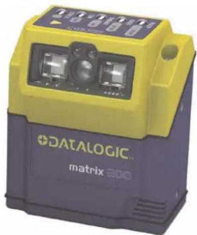
natural_image
Exterior view of a Datalogic matrix 200 device (no visible text or symbols on body)Reference Manual
DATALOGIC™
Datalogic Automation S.r.l.
Via S. Vitalino 13
Datalogic reserves the right to make modifications and improvements without prior notification.
Datalogic shall not be liable for technical or editorial errors or omissions contained herein, nor for incidental or consequential damages resulting from the use of this material.
Product names mentioned herein are for identification purposes only and may be trademarks and or registered trademarks of their respective companies.
Datalogic is a registered trademark of Datalogic S.p.A. in many countries and the Datalogic logo is a trademark of Datalogic S.p.A.
© Datalogic Automation S.r.l. 2007 - 2008
REFERENCES ...... vi
Conventions......vi
Reference Documentation.... vi
Service and Support ...... vi
Patents......vi
COMPLIANCE......vii
EMC Compliance......vii
Power Supply......vii
LED Class......vii
CE Compliance......vii
FCC Compliance ......vii
HANDLING......viii
GENERAL VIEW....x
1 RAPID CONFIGURATION .... 1
Step 1 – Connect the System....1
Step 2 – Mount and Position the Reader....6
Step 3 – Aim the Reader ....7
Step 4 – X-PRESS ^TM Configuration....8
Step 5 – Installing VisiSet™ Configuration Program ......9
Step 6 – Configuration Using Autolearning Wizard ...... 10
Step 7 – Test Mode ...... 13
Advanced Reader Configuration....14
2 INTRODUCTION 15
2.1 Product Description 15
2.2 Indicators and Keypad Button....18
2.5 Model Description....24
2.6 Accessories 25
2.7 Application Examples 25
3 INSTALLATION 28
3.1 Package Contents 28
3.2 Mechanical Dimensions....29
3.3 Mounting and Positioning Matrix 200 ^TM 31
4 CBX ELECTRICAL CONNECTIONS....33
4.1 Power Supply....34
4.2 Main Serial Interface....34
4.2.1 RS232 Interface 35
4.2.2 RS485 Full-Duplex Interface....36
4.2.3 RS485 Half-Duplex Interface 37
4.4 Auxiliary RS232 Interface 44
4.5 Inputs....45
4.6 Outputs 48
4.7 User Interface - Host....50
5 25-PIN CABLE ELECTRICAL CONNECTIONS....51
5.1 25-Pin Connector....51
5.2 Power Supply....52
5.3 Main Serial Interface....52
5.3.1 RS232 Interface....53
5.3.2 RS485 Full-Duplex Interface....54
5.3.3 RS485 Half-Duplex Interface 55
5.5 Auxiliary RS232 Interface 62
5.6 Inputs....63
5.7 Outputs 66
5.8 User Interface 68
6 TYPICAL LAYOUTS 69
6.1 Point-to-Point 69
6.2 Pass-Through 71
6.3 ID-NET™ 72
6.4 RS232 Master/Slave....75
6.5 Multiplexer 76
6.6 USB Connection (Matrix 200 XXX-x2x models only)....77
7 READING FEATURES....78
7.1 Maximum Line Speed Calculation 79
8 SOFTWARE CONFIGURATION....81
8.1 VisiSet™ System Requirements....81
8.2 Installing VisiSet™ 81
8.3 Startup 82
8.3.1 VisiSet™ Options....83
8.4 Configuration 85
8.4.1 Edit Reader Parameters 86
8.4.2 Send Configuration Options....88
8.4.3 Calibration....91
8.4.4 Multi Image Acquisition Settings....95
8.4.5 Run Time Self Tuning (RTST) 95
8.4.6 Region Of Interest Windowing 96
8.4.7 Direct Part Marking Applications....97
8.5 Image Capture and Decoding....99
8.6 Statistics 99
9 MAINTENANCE 100
9.1 Cleaning....100
10 TROUBLESHOOTING 101
10.1 General Guidelines....101
11 TECHNICAL FEATURES....104
GLOSSARY....106
INDEX....109
CONVENTIONS
This manual uses the following conventions:
"User" refers to anyone using a Matrix 200 ^TM reader.
"Reader" refers to the Matrix 200 ^TM reader.
"You" refers to the System Administrator or Technical Support person using this manual to install, configure, operate, maintain or troubleshoot a Matrix 200™ reader.
REFERENCE DOCUMENTATION
For further details refer to: the VisiSet™ Help On Line, Matrix Reading Methods, Matrix Host Mode Programming, Matrix SW Parameter Guide, Matrix Code Quality Verifier Solution provided as supplementary documentation on CD-ROM.
SERVICE AND SUPPORT
Datalogic provides several services as well as technical support through its website. Log on to www.automation.datalogic.com and click on the links indicated for further information including:
- PRODUCTS
Search through the links to arrive at your product page where you can download specific Manuals and Software & Utilities
- VisiSet™ a utility program, which allows device configuration using a PC. It provides RS232 and USB interface configuration.
• SERVICES & SUPPORT
- Datalogic Services - Warranty Extensions and Maintenance Agreements
- Authorised Repair Centres
- CONTACT US
E-mail form and listing of Datalogic Subsidiaries
PATENTS
This product is covered by one or more of the following patents:
U.S. patents: 6,512,218 B1; 6,616,039 B1; 6,808,114 B1; 6,997,385 B2; 7,102,116 B2; 7,282,688 B2
European patents: 999,514 B1; 1,014,292 B1; 1,128,315 B1.
Additional patents pending.
For installation, use and maintenance it is not necessary to open the reader.
EMC COMPLIANCE
In order to meet the EMC requirements:
- connect reader chassis to the plant earth ground by means of a flat copper braid shorter than 100 mm;
- for CBX connections, connect the pin "Earth" to a good Earth Ground;
- for direct connections, connect the main interface cable shield to pin 1 of the 25-pin connector.
POWER SUPPLY
ATTENTION: READ THIS INFORMATION BEFORE INSTALLING THE PRODUCT
This product is intended to be installed by Qualified Personnel only.
This product is intended to be connected to a UL Listed Computer which supplies power directly to the reader or a UL Listed Direct Plug-in Power Unit marked LPS or "Class 2", rated 10 to 30 V, minimum 500 mA.
LED CLASS
Class 1 LED Product to EN60825-1:2001
CE COMPLIANCE
Warning: This is a Class A product. In a domestic environment this product may cause radio interference in which case the user may be required to take adequate measures.
FCC COMPLIANCE
Modifications or changes to this equipment without the expressed written approval of Datalogic could void the authority to use the equipment.
This device complies with PART 15 of the FCC Rules. Operation is subject to the following two conditions: (1) This device may not cause harmful interference, and (2) this device must accept any interference received, including interference which may cause undesired operation.
This equipment has been tested and found to comply with the limits for a Class A digital device, pursuant to part 15 of the FCC Rules. These limits are designed to provide reasonable protection against harmful interference when the equipment is operated in a commercial environment. This equipment generates, uses, and can radiate radio frequency energy and, if not installed and used in accordance with the instruction manual, may cause harmful interference to radio communications. Operation of this equipment in a residential area is likely to cause harmful interference in which case the user will be required to correct the interference at his own expense.
The Matrix 200 ^™ is designed to be used in an industrial environment and is built to withstand vibration and shock when correctly installed, however it is also a precision product and therefore before and during installation it must be handled correctly to avoid damage.
- avoid that the readers are dropped (exceeding shock limits).

- do not fine tune the positioning by striking the reader or bracket.

- do not weld the reader into position which can cause electrostatic, heat or reading window damage.

- do not spray paint near the reader which can cause reading window damage.

Matrix 200 ^TM

Figure A
① Mounting Holes (4)
② "POWER ON" LED
③ Device Class Labels Reading Window
④ HMI X-PRESS™ Interface
1 RAPID CONFIGURATION
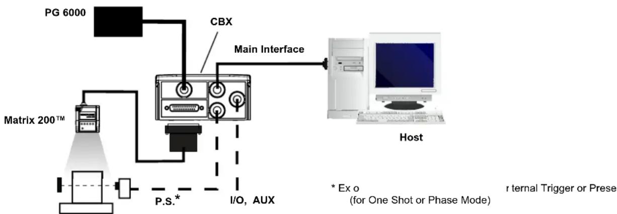
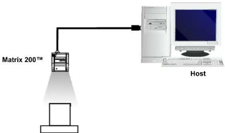
To connect the system in a Stand Alone configuration, you need the hardware indicated in Figure 1. In this layout the data is transmitted to the Host on the main serial interface. Data can also be transmitted on the RS232 auxiliary interface independently from the main interface selection.
When One Shot or Phase Mode Operating mode is used, the reader is activated by an External Trigger (photoelectric sensor) when the object enters its reading zone.
flowchart
graph TD
    A["PG 6000"] --> B["Matrix 200™"]
    B --> C["P.S.*"]
    C --> D["I/O, AUX"]
    D --> E["Main Interface"]
    E --> F["Host"]
    G["CBX"] --> E
    H["* Ex o (for One Shot or Phase Mode)"] --> E
    I["r ternal Trigger or Prese"] --> E
Figure 1 – Matrix 200 ^TM in Stand Alone Layout
CBX100/CBX500 Pinout for Matrix 200™ 25-Pin Models
The table below gives the pinout of the CBX100/CBX500 terminal block connectors. Use this pinout when the Matrix 200 ^™ reader is connected by means of the CBX100/CBX500:
| CBX100/500 Terminal Block Connectors | |||
| Input Power Outputs | |||
| Vdc Power Supply Input Voltage + +V Power Source - Outputs | |||
| GND Power Supply Input Voltage - -V Power Reference - Outputs | |||
| Earth Protection Earth Ground O1+ Output 1 + | |||
| O1- Output 1 - | |||
| Inputs | O2+ Output 2 + | ||
| +V Power Source – External Trigger O2- Output 2 - | |||
| I1A | External Trigger A (polarity insensitive) | Auxiliary Interface | |
| I1B | External Trigger B (polarity insensitive) | TX | Auxiliary Interface TX |
| -V | Power Reference – External Trigger | RX | Auxiliary Interface RX |
| +V Power Source – Inputs | SGND Auxiliary Interface Reference | ||
| I2A | Input 2 A (polarity insensitive) | ID-NETTM | |
| I2B | Input 2 B (polarity insensitive) | REF | Network Reference |
| -V Power Reference – Inputs | ID+ ID-NETTM network + | ||
| Shield | ID- | ID-NETTM network - | |
| Shield | Network Cable Shield | ||
| Main Interface | |||
| RS232 | RS485 Full-Duplex | RS485 Half-Duplex | |
| TX | TX+ | RTX+ | |
| RTS | TX- | RTX- | |
| RX | *RX+ | ||
| CTS | *RX- | ||
| SGND | SGND | SGND | |
* Do not leave floating, see par. 4.2.2 for connection details.

CAUTION
Do not connect GND, SGND and REF to different (external) ground references. GND, SGND and REF are internally connected through filtering circuitry which can be permanently damaged if subjected to voltage drops over 0.8 Vdc.
25-Pin Connector Pinout for Matrix 200™ 25-Pin Models
The table below gives the pinout of the 25-pin male D-sub connector for connection to the power supply and input/output signals. Use this pinout when the Matrix 200 ^™ reader is connected by means of the 25-pin connector:
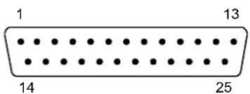
Figure 2 - 25-pin Male D-sub Connector
| 25-pin D-sub male connector pinout | ||||
| Pin | Name | Function | ||
| 13, 9 Vdc | Power supply input voltage + | |||
| 25, 7 GND | Power supply input voltage - | |||
| 1 CHAS | SIS Cable shield connected to chassis | |||
| 18 I1A | External Trigger A (polarity insensitive) | |||
| 19 I1B | External Trigger B (polarity insensitive) | |||
| 6 I2A | Input 2 A (polarity insensitive) | |||
| 10 I2B | Input 2 B (polarity insensitive) | |||
| 8 O1+ | Output 1 + | |||
| 22 O1- | Output 1 - | |||
| 11 O2+ | Output 2 + | |||
| 12 O2- | Output 2 - | |||
| 20 RX | Auxiliary RS232 RX | |||
| 21 TX | Auxiliary RS232 TX | |||
| 23 | ID+ | ID-NETTM network + | ||
| 24 | ID- | ID-NETTM network - | ||
| 14, 15, 16, 17 | NC | Not Connected | ||
| Pin | Name | RS232 | RS485Full-Duplex | RS485Half-Duplex |
| 2 | TX | TX+ | RTX+ | |
| 3 | MAIN INTERFACE(SW SELECTABLE) | RX | *RX+ | |
| 4 | RTS | TX- | RTX- | |
| 5 | CTS *RX- | |||
* Do not leave floating, see par. 5.3.2 for connection details.
USB Models

NOTE
Before connecting the reader to the USB Port, Install the USB Virtual COM Port Driver from the Support Files\USB Virtual COM Port Drivers directory on the VisiSet CD-ROM.
The USB Virtual COM Port Driver allows sending serial data using the Matrix 200 ^™ USB port. A different virtual COM Port will be assigned to each connected reader.
Installing the USB Virtual COM port drivers:
- Double-click on the following file to launch the USB Virtual COM Port Driver Installer.
Windows XP = "DPInst.exe" Windows Vista = "DPInst64.exe"
For other operating systems see the readme txt in the Support Files\USB Virtual COM Port Drivers directory. For updated drivers or more details go to ftdichip.com/Drivers/VCP.htm.
Configuring the USB Virtual COM port:
Connect the Matrix 200 ^™ USB reader to your PC; a new virtual COM port is associated with the reader. Follow these steps to configure the associated COM Port:
- Right-click on "My Computer" in the Windows "Start" menu and select "Properties".
- Select the "Hardware" tab in the System Properties dialog and click the "Device Manager" button.
- Expand the "Ports (COM & LPT)" item on the "Device Manager" menu. Right-click on "USB Serial Port" and select "Properties".
-
Select the "Port Settings" tab in the "Properties" dialog and click the "Advanced" button.
-
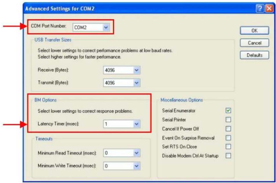
From the "Advanced Settings for COMx" dialog:
-
Expand the "COM Port Number" menu and select a new COM Port number if desired (optional).
- Set the "BM Options" -> "Latency Timer" (msec) parameter to 1.
You are now ready to use the new COM Port.
Matrix 200 ^™ USB models can be connected in a Point-to-Point layout to a local host through their USB cable. No external power supply is necessary.
flowchart
graph TD
    A["Computer"] -->|200TM Matrix| B["Server"]
    B --> C["Host"]
Figure 3 – Matrix 200™ USB Model in a Point-to-Point Layout
STEP 2 – MOUNT AND POSITION THE READER
- To mount the Matrix 200 ^™ , use the mounting brackets to obtain the most suitable position for the reader. Two of the most common mounting configurations are shown in the figures below. Other mounting solutions are provided in par. 3.3.
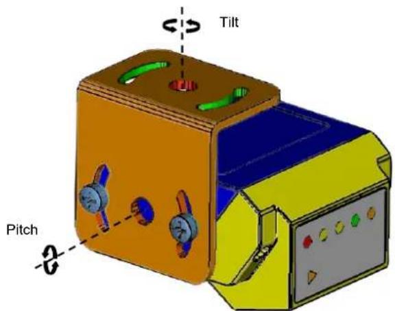
Figure 4 –Positioning 90° Model with Mounting Bracket
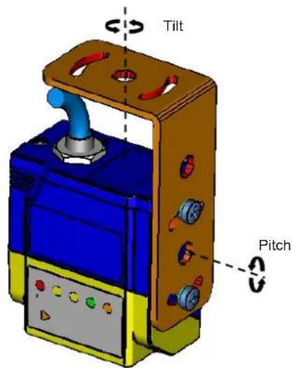
Figure 5 –Positioning Straight Model with Mounting Bracket
- When mounting the Matrix 200 ^™ take into consideration these three ideal label position angles: Pitch or Skew 10° to 20° and Tilt 0°, although the reader can read a code at any tilt angle.
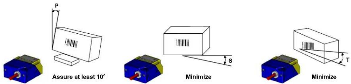
Figure 6 – Pitch, Skew and Tilt Angles
- Refer to the Reading Features table in chp. 7 to determine the distance your reader should be positioned at.

NOTE
Rapid Configuration of the Matrix 200 ^™ reader can be made either through the X-PRESS ^™ interface (steps 3-4) which requires no PC connection, or by using the VisiSet ^™ Autolearning Wizard (steps 5-6). Select the procedure according to your needs.
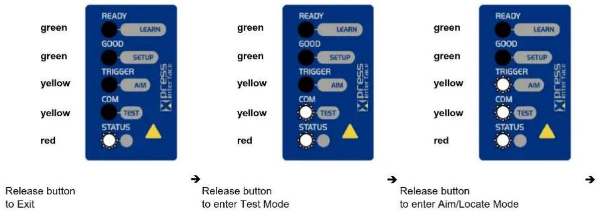
STEP 3 – AIM THE READER
Matrix 200 ^™ provides a built-in aiming system to aid reader positioning. The aiming system is accessed through the X-PRESS ^™ Interface.
- Power the reader on. During the reader startup (reset or restart phase), all the LEDs blink for one second. On the connector side of the reader near the cable, the "POWER ON" LED (blue) indicates the reader is correctly powered.
- Enter the Aim/Locate function by pressing and holding the X-PRESS™ push button until the Aim LED is on.
- Release the button to enter the Aim function. The blue ring turns on.
- Place the application specific code in front of the reader at the reading distance indicated for your model in the Reading Features table, centering it in the blue ring.

Figure 7 – Aim Function Using The Blue Ring
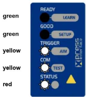
Figure 8 – X-PRESS™ Interface: Aim Function
- Exit the Aim function by pressing the X-PRESS™ push button once. The blue ring turns off.
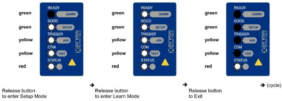
STEP 4 - X-PRESS™ CONFIGURATION
Once Matrix 200 ^TM is positioned with respect to the code (step 3), you can configure it for optimal code reading relative to your application. This configuration can be performed either through the X-PRESS ^TM Interface or the VisiSet ^TM configuration program.
Setup
- Enter the Setup function by pressing and holding the X-PRESS™ push button until the Setup LED is on.
- Release the button to enter the Setup function. The Setup LED will blink until the procedure is completed.
The Setup procedure ends when the Image Acquisition parameters are successfully saved in the reader memory, the Setup LED will remain on continuously and Matrix 200 ^™ emits 3 high pitched beeps.
If the calibration cannot be reached after a timeout of about 5 (five) seconds Matrix 200 ^TM will exit without saving the parameters to memory, the Setup LED will not remain on continuously but it will just stop blinking. In this case Matrix 200 ^TM emits a long low pitched beep.
- Exit the Setup function by pressing the X-PRESS™ push button once.
green
green
yellow
yellow
red
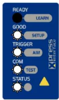
Figure 9 – X-PRESS™ Interface: Setup Function
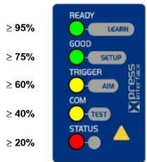
Learn
- Enter the Learn function by pressing and holding the X-PRESS™ push button until the Learn LED is on.
- Release the button to enter the Learn function. The Learn LED will blink until the procedure is completed.
The Learn procedure ends when the Image Processing and Decoding parameters are successfully saved in the reader memory, the Learn LED will remain on continuously, the Green Spot is activated and Matrix 200 ^™ emits 3 high pitched beeps.
If the calibration cannot be reached after a timeout of about 3 (three) minutes Matrix 200 ^™ will exit without saving the parameters to memory, the Learn LED will not remain on continuously but it will just stop blinking. In this case Matrix 200 ^™ emits a long low pitched beep.
- Exit the Setup function by pressing the X-PRESS™ push button once.
green
green
yellow
yellow
red
Figure 10 – X-PRESS™ Interface: Learn Function
If you have used this procedure to configure Matrix 200 ^TM go to step 7.
STEP 5 – INSTALLING VISISET™ CONFIGURATION PROGRAM
VisiSet ^™ is a Datalogic reader configuration tool providing several important advantages:
- Autolearning Wizard for rapid configuration and new users;
- Defined configuration directly stored in the reader;
- Communication protocol independent from the physical interface allowing to consider the reader as a remote object to be configured and monitored.
To install VisiSet ^™ , turn on the PC that will be used for the configuration, running Windows 98, 2000/NT, XP or Vista, then insert the VisiSet ^™ CD-ROM, wait for the CD to autorun and follow the installation procedure.
This configuration procedure assumes a laptop computer, running VisiSet ^™ , is connected to the reader's auxiliary port.
After installing and running the VisiSet™ software program the following window:
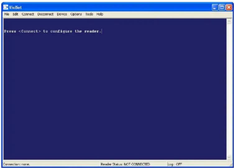
Figure 11 - VisiSet™ Opening Window
Set the communication parameters from the "Options" menu. Then select "Connect", the following window appears:
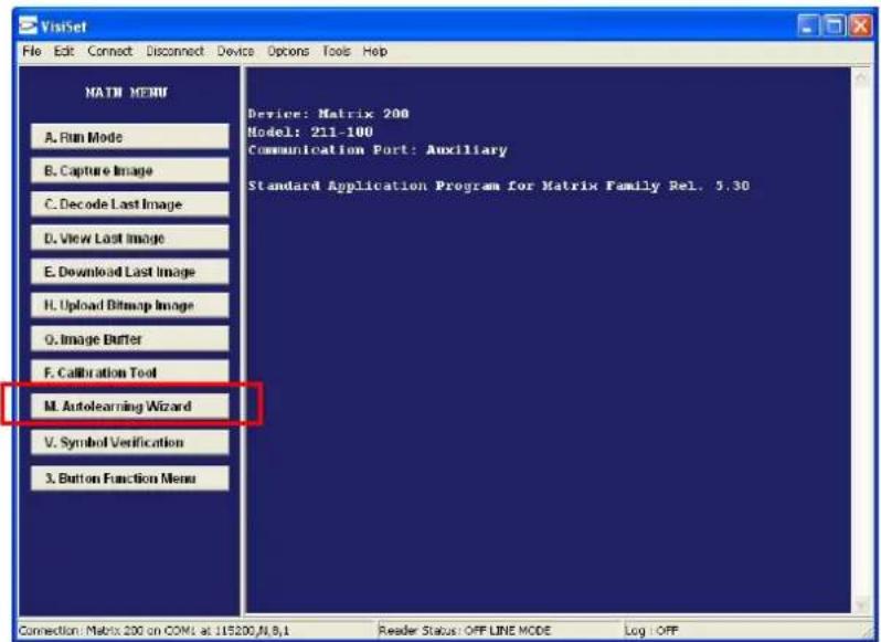
Figure 12 - VisiSet™ Main Window After Connection
STEP 6 – CONFIGURATION USING AUTOLEARNING WIZARD
The Autolearning Wizard option is advised for rapid configuration or for new users. It allows reader configuration in a few easy steps.
- Select the Autolearning Wizard button from the Main menu.
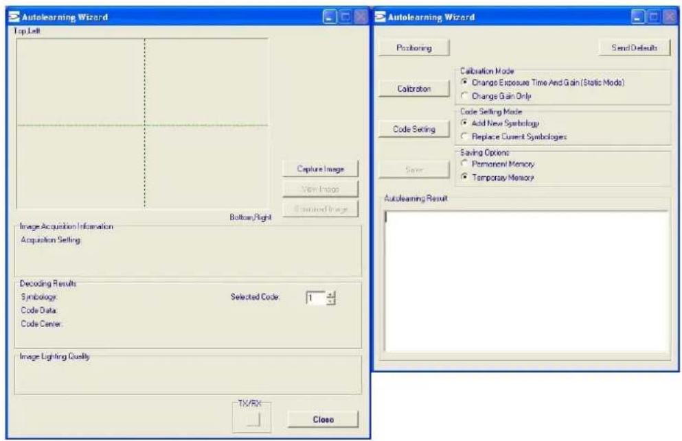
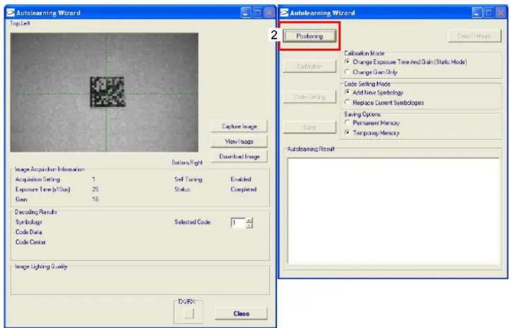
Place the application specific code in front of the reader at the correct reading distance (see step 2 and the Reading Features table in the chp. 7).
- Press the "Positioning" button. The reader continuously acquires images and gives visual feedback in the view image window. Move the reader (or code) to center it. Press the Positioning button again to stop positioning.
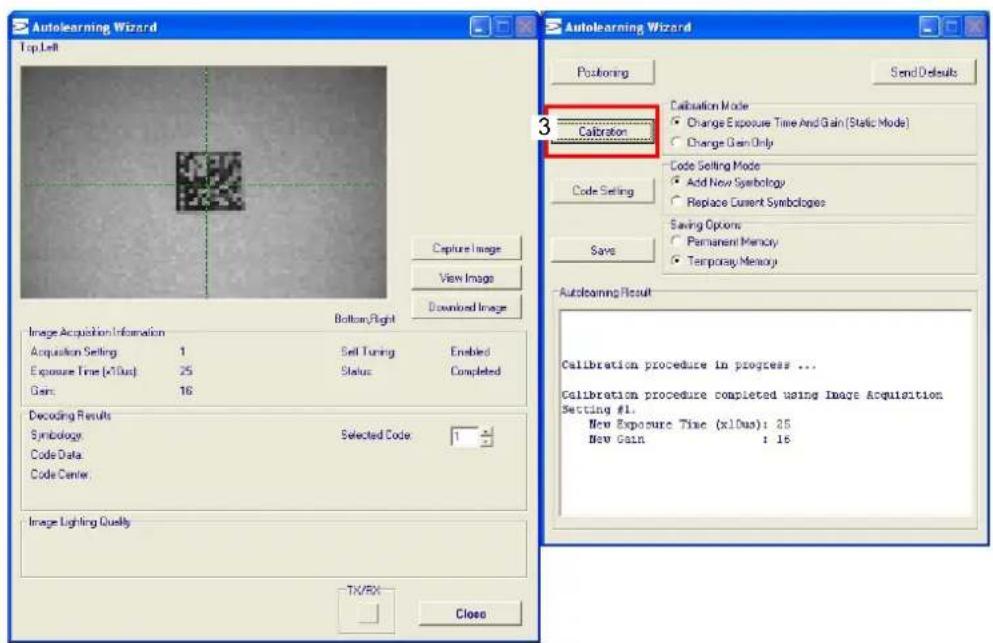
- Select a Calibration Mode choice and press the "Calibrate" button. The reader flashes once acquiring the image and auto determines the best exposure and gain settings. If the code symbology is enabled by default, the code will also be decoded.
- Select a Code Setting Mode choice and press the "Code Setting" button.
The Autolearning Result section of the Autolearning Wizard window shows the code type results and the parameter settings.
- Select a Saving Options choice and press the "Save" button.
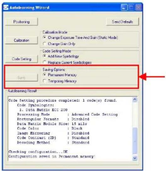
- Close the AutoLearning Wizard.

NOTE
If your application has been configured using the VisiSet™ Autolearning Wizard, your reader is ready. If necessary you can use VisiSet™ for advanced reader configuration.
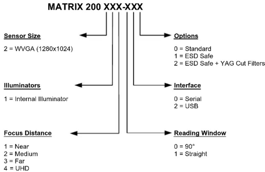
STEP 7 - TEST MODE
Use a code suitable to your application to test the reading performance of the system. Alternatively, you can use the Datalogic 1D/2D Test Chart (Code 39, Data Matrix ECC 200).
- Enter the Test function by pressing and holding the X-PRESS™ push button until the Test LED is on.
- Release the button to enter the Test function.
Once entered, the Bar Graph on the five LEDs is activated and if the reader starts reading codes the Bar-Graph shows the Good Read Rate. In case of no read condition, only the STATUS LED is on and blinks.
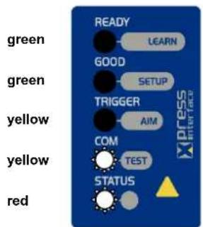
Figure 13 – X-PRESS™ Interface: Test Function
- To exit the Test, press the X-PRESS™ push button once.

NOTE
By default, the Test exits automatically after three minutes.
The Bar Graph has the following meaning:
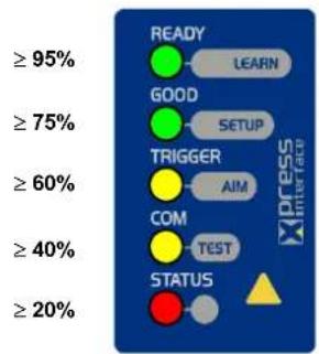
Figure 14 – Test Bar Graph
For further details on advanced product configuration, refer to the VisiSet™ Help On-Line.
The following are alternative or advanced reader configuration methods:
Advanced Configuration Using VisiSet™
Advanced configuration can be performed through the VisiSet™ program by selecting Device> Get Configuration From Temporary Memory to open the Parameter Setup window in off-line mode. Advanced configuration is addressed to expert users being able to complete a detailed reader configuration. The desired parameters can be defined in the various folders of the Parameter Setup window and then sent to the reader memory (either Temporary or Permanent):
Figure 15 - VisiSet™ Parameter Setup Window
Host Mode Programming
The reader can also be configured from a host computer using the Host Mode programming procedure, by commands via the serial interface. See the Host Mode Programming file on the CD-ROM.
Alternative Layouts
If you need to install an ID-NET ^™ network, Fieldbus network, Pass-Through network, Multiplexer network or an RS232 Master/Slave refer to the Matrix 200 ^™ Reference Manual.
Code Quality Verification
Matrix 200 ^™ can be used as a Code Quality Verifier according to the ISO/IEC 15415, ISO/IEC 15416, AS9132, and AIM DPM Standards.
2 INTRODUCTION
2.1 PRODUCT DESCRIPTION
Matrix 200 ^™ is the new Datalogic 2D reader offering excellent reading performance, ultra compact size and extreme ease of use. Thanks to innovative optical features, advanced software functions and complete connectivity options, Matrix 200 ^™ is the cost effective solution for applications where the space is very limited.
Ultra Compact Size
Compact dimensions, straight and 90^ reading window models availability allow flexible mounting and positioning in narrow spaces.
Excellent Reading Performance
WVGA image sensor, up to 60 frames/s acquisition rate and dynamic reading capability, together with powerful decoding libraries provide excellent performance on a wide range of code symbologies as well as damaged and low quality codes. Matrix 200 ^™ allows reading 10 mils codes in moving applications at speeds up to 2 m/sec.
Innovative Optical Features
The innovative optical and lighting systems ensure wide field of view at short reading distances, combined with excellent illumination pattern. Matrix 200 ^™ has a maximum reading distance of 200 mm, and it can read at near distance ultra high density 2D codes up to 0.076 mm (3 mils).
Ease Of Use
The intuitive X-PRESS™ Human Machine Interface makes installation and maintenance easier than ever thanks to a five LED bar graph and the multi-function key providing immediate access to relevant functions such as Aiming, Setup (for automatic imager calibration), Learn (for automatic code setting), Test Mode (for bar graph activation). A Green Spot provides immediate Good Read feedback.
Enhanced Connectivity
An embedded high speed ID-NET ^™ communication interface allows efficient data collection and simplifies network wiring. USB interface models allow direct connection to a PC.
Industrial Features
Matrix 200 ^™ , with its rugged construction, IP65 protection class, 50°C max operating temperature and 10 to 30 VDC power supply is the ideal product for industrial applications.
Matrix 200 ^™ has been developed for use in numerous industries like:
Electronics:
PCB Board Tracking
Electronics Product Tracking
Pharmaceutical & Chemical:
■ Medical Devices Traceability
■ Pharmaceutical and Medicine Manufacturing
OEM:
■ Chemical & Biomedical Analysis Machines
■ Access Control Systems
■ Self Service Systems (ATM, Kiosks)
Print & Apply systems
Document Handling
This technology intrinsically provides omni-directional reading.
Standard Application Program
A Standard Application Program is factory-loaded onto Matrix 200 ^™ . This program controls code reading, data formatting, serial port USB interfacing, and many other operating and control parameters. It is completely user configurable from a Laptop or PC using the dedicated configuration software program VisiSet ^™ , provided on CD-ROM with the reader.
There are different programmable operating modes to suit various code reading system requirements.
Quick, automatic positioning, calibration and code setting of the imager can be accomplished using the X-PRESS™ button and LEDs on top of the reader without the necessity of a PC.
The previous functions can also be performed through VisiSet ^™ through the Autolearning Wizard. This tool includes visual feedback from the reader.
VisiSet ^™ provides a Calibration Tool to verify the exact positioning of the reader and to maximize its reading performance.
Statistics on the reading performance can also be visualized through a dedicated window in VisiSet ^™ .
Symbol Verification can be performed through VisiSet ^™ when the reader has been installed and setup as a Verifier station.
Programmability
If your requirements are not met by the Standard Application Program, Custom Application Programs can be requested at your local Datalogic distributor.
Some of the main features of this reader are given below:
- Ultra Compact Dimensions
- Direct and 90^ window models for smart mounting
- Outstanding decoding capability on 1D, 2D, Stacked and Postal symbologies
• High performance on dynamic reading applications - X-PRESS™ for easy and intuitive setup
• Optical Aiming System
• 10 to 30 VDC Power Supply - USB Connectivity
- ID-NET™ embedded high speed connectivity
- Region Of Interest Windowing for higher frame rate
- Run Time Self Tuning for higher flexibility
2.2 INDICATORS AND KEYPAD BUTTON
Figure 16 - Indicators
The following LED indicators are located on the reader:
| PWR | blue LED indicates that the reader is connected to the power supply (Figure 16, 1) |
In normal operating mode the colors and meaning of the five LEDs are illustrated in the following table:
| READY | green LED indicates that the reader is ready to operate (Figure 16, 2) |
| GOOD | green LED confirms successful reading (Figure 16, 3) |
| TRIGGER | yellow LED indicates the status of the reading phase (Figure 16, 4) |
| COM | yellow LED indicates active communication on the main serial port * (Figure 16, 5) |
| STATUS | red LED indicates a NO READ result (Figure 16, 6) |
* When connected to a Fieldbus network through the CBX500, the COM LED is always active, even in the absence of data transmission, because of polling activity on the Fieldbus network.
During the reader startup (reset or restart phase), these five LEDs blink for one second.
In X-PRESS™ Configuration mode the colors and meaning of these five LEDs are described in par. 2.4.
The keypad button (Figure 16, 7), is software programmable. By default it starts the X-PRESS™ interface for quick installation without using a PC (see chp. 1).
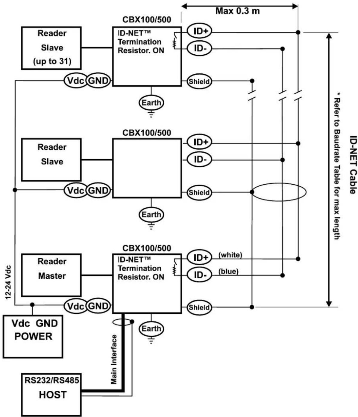
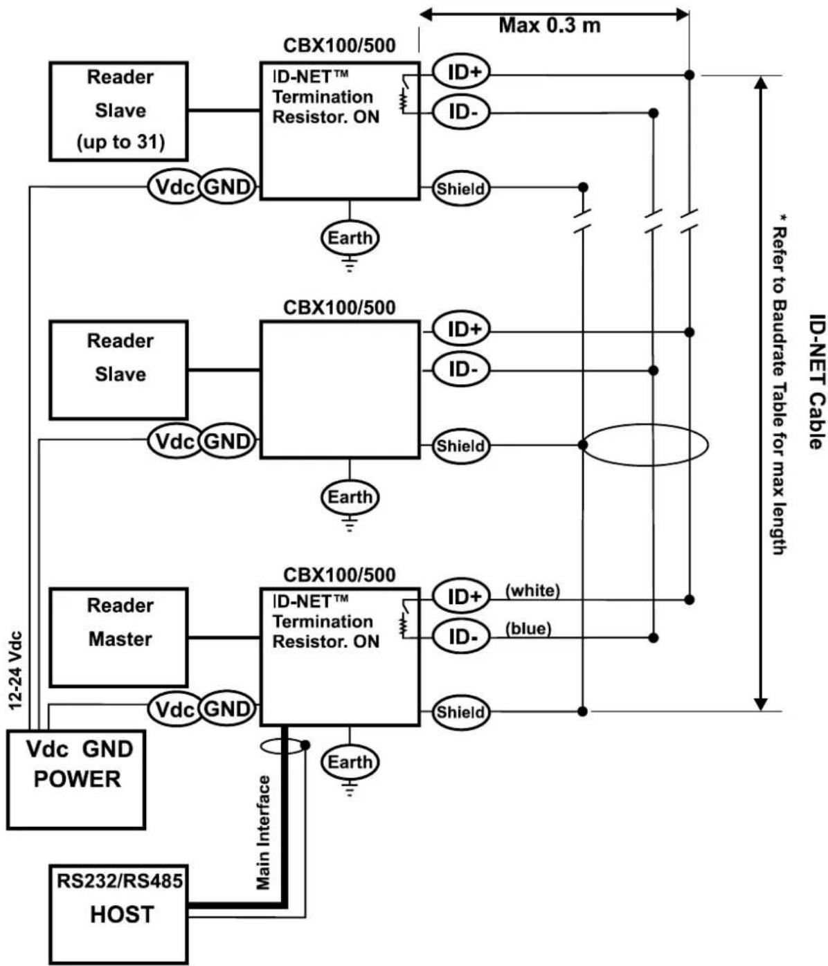
2.3 ID-NET™
The ID-NET ^™ network is a built-in high-speed interface dedicated for high-speed reader interconnection. ID-NET ^™ is in addition to the Main and Auxiliary serial interfaces.

The following network configurations are available:
- ID-NET™ M/S Synchronized: Single station – multiple readers
flowchart
graph TD
    A["Satellite"] --> B["CBX100"]
    A --> C["CBX100"]
    A --> D["CBX100"]
    B --> E["ID NET™"]
    C --> E
    D --> E
ID-NET™ interface allows local connection of multiple readers reading different sides of the same target. All readers share a single presence sensor and activate/deactivate simultaneously.
At the end of each reading phase a single data message is transmitted to the host.
Thanks to ID-NET™, data communication among readers is highly efficient so that an immediate result will be available.
- ID-NET™ M/S Multidata: Multiple stations – single reader
flowchart
graph TD
    A["Device 1"] -->|Wireless Link| B["Device 2"]
    C["Device 3"] -->|Wireless Link| D["Device 4"]
    E["Device 5"] -->|Wireless Link| F["Device 6"]
    G["Device 7"] -->|Wireless Link| H["Device 8"]
    I["Device 9"] -->|Wireless Link| J["Device 10"]
    K["Device 11"] -->|Wireless Link| L["Device 12"]
    M["Device 13"] -->|Wireless Link| N["Device 14"]
    O["Device 15"] -->|Wireless Link| P["Device 16"]
    Q["Device 17"] -->|Wireless Link| R["Device 18"]
    S["Device 19"] -->|Wireless Link| T["Device 20"]
    U["Device 21"] -->|Wireless Link| V["Device 22"]
    W["Device 23"] -->|Wireless Link| X["Device 24"]
    Y["Device 25"] -->|Wireless Link| Z["Device 26"]
    AA["Device 27"] -->|Wireless Link| AB["Device 28"]
    AC["Device 29"] -->|Wireless Link| AD["Device 30"]
    AE["Device 31"] -->|Wireless Link| AF["Device 32"]
    AG["Device 33"] -->|Wireless Link| AH["Device 34"]
    AI["Device 35"] -->|Wireless Link| AJ["Device 36"]
    AK["Device 37"] -->|Wireless Link| AL["Device 38"]
    AM["Device 39"] -->|Wireless Link| AN["Device 40"]
    AO["Device 41"] -->|Wireless Link| AP["Device 42"]
    AQ["Device 43"] -->|Wireless Link| AR["Device 44"]
    AS["Device 45"] -->|Wireless Link| AT["Device 46"]
    AU["Device 47"] -->|Wireless Link| AV["Device 48"]
    AW["Device 49"] -->|Wireless Link| AX["Device 50"]
    AY["Device 51"] -->|ID NET™| AZ["Data Structure"]
    style A fill:#f9f,stroke:#333
    style B fill:#ccf,stroke:#333
    style AC fill:#ccf,stroke:#333
    style AD fill:#ccf,stroke:#333
    style AE fill:#ccf,stroke:#333
    style AF fill:#ccf,stroke:#333
    style AG fill:#ccf,stroke:#333
    style AH fill:#ccf,stroke:#333
    style AI fill:#ccf,stroke:#333
    style AJ fill:#ccf,stroke:#333
    style AK fill:#ccf,stroke:#333
    style AL fill:#ccf,stroke:#333
    style AM fill:#ccf,stroke:#333
    style AN fill:#ccf,stroke:#333
    style AO fill:#ccf,stroke:#333
    style AP fill:#ccf,stroke:#333
    style AQ fill:#ccf,stroke:#333
    style AR fill:#ccf,stroke:#333
    style AS fill:#ccf,stroke:#333
    style AT fill:#ccf,stroke:#333
    style AU fill:#ccf,stroke:#333
    style AV fill:#ccf,stroke:#333
    style AW fill:#ccf,stroke:#333
    style AX fill:#ccf,stroke:#333
ID-NET™ interface allows connection of readers reading objects placed on independent conveyors. All readers are typically located far away from each other and they use a dedicated presence sensor.
At the end of each reading phase, each reader transmits its own data message to the host. Thanks to ID-NET ^™ , data collection among readers is accomplished at a high speed without the need of an external multiplexing device. This leads to an overall cost reduction and to a simple system wiring.
2.3.1 How To Setup/Configure the Reader Network
A complete ID-NET ^™ reader network can be easily setup through VisiSet ^™ as follows:
Mounting & Connection
- Mechanically mount/install all the readers (refer to par. 3.2 and 3.3).
- Wire ID-NET ^™ (refer to par. 4.3 or 5.4).
- Power up the entire system.
Configuration of Slaves
- Connect a PC equipped with VisiSet™ to the Main, or Auxiliary interface of the planned Slave reader.
- Launch VisiSet™ and connect to the Slave reader.
- From the VisiSet™ Device Menu select "Parameter Setup".
- Set the Role of the Slave reader (Synchronized or Multidata) from the Reading System Layout > Device Network Setting > Topology Role parameter.
- Set the Slave Address according to the desired value 0-31 from the Reading System Layout > Device Network Setting > Slave Address parameter. Each reader must have a different Address on the ID-NET™ Network.
-
If necessary, set the ID-NET™ baudrate from the Reading System Layout > Device Network Setting > Network Baud Rate parameter, (500 kbs default).
-
Configure the other device parameters via VisiSet™ [Operating Mode, Calibration, Data Collection parameters, etc.].
- If using the CBX connection box equipped with a BM100 Backup module, perform Device Backup at the Slave.
The Slave device is now Configured. Repeat these steps for each Slave reader in the ID-NET ^™ network.
Configuration of Master
- Connect a PC equipped with VisiSet™ to the Main, or Auxiliary interface of the planned Master reader.
- Launch VisiSet™ and connect to the Master reader.
- From the VisiSet™ Device Menu select "Parameter Setup".
- Set the Role of the Master reader (Synchronized or Multidata) from the Reading System Layout > Device Network Setting > Topology Role parameter.
- Enable the planned Slave device N from the Reading System Layout > Expected Slave Device #N > Status parameter and, if desired, set the related identification string from the Expected Slave Device #N > Device Description parameter. Repeat this step for all planned Slave devices.
- If necessary, set the ID-NET™ baudrate from the Reading System Layout > Device Network Setting > Network Baud Rate parameter, (500 kbs default).
- Configure the other device parameters via VisiSet™ [Operating Mode, Calibration, Data Collection parameters, etc.].
- If using the CBX connection box equipped with a BM100 Backup module, perform Device Backup at the Master.
- From the VisiSet™ Device Menu select "ID-NET™ Status Window" and click on the "Look For Devices On Network" button to check the status of the expected Slave devices within the ID-NET™ network.
The reader network is ready.
2.4 X-PRESS™ HUMAN MACHINE INTERFACE
X-PRESS ^™ is the intuitive Human Machine Interface designed to improve ease of installation and maintenance.
Status information is clearly presented by means of the five colored LEDs, whereas the single push button gives immediate access to the following relevant functions:
- Learn to self-detect and auto-configure for reading unknown codes.
- Setup to perform Exposure Time and Gain calibration.
- Aim/Locate to turn on the blue ring to aid positioning.
- Test with bar graph visualization to check static reading performance.
flowchart
graph TD
    A["READY"] --> B["LEARN"]
    C["GOOD"] --> D["SETUP"]
    E["TRIGGER"] --> F["AIM"]
    G["COM"] --> H["TEST"]
    I["STATUS"] --> J["△"]
2.4.1 X-PRESS™ Functions
Quick access to the following functions is provided by an easy procedure using the push button:
1 - Press the button (the Status LED will give a visual feedback).
2 - Hold the button until the specific function LED is on (Test, Focus, Setup or Learn).
3 - Release the button to enter the specific function.
Once button is pressed, the cycle of LEDs activation is as follows:
flowchart
graph LR
    A["Green"] --> B["READY"]
    C["Yellow"] --> D["GOOD"]
    E["Red"] --> F["STATUS"]
    B --> G["Xpress Interface"]
    D --> H["SETUP"]
    F --> I["TRIGGER"]
    J["COM"] --> K["AIM"]
    L["TEST"] --> M["STATUS"]
    N["GREEN"] --> O["GOOD"]
    P["GREEN"] --> Q["SETUP"]
    R["yellow"] --> S["TRIGGER"]
    T["yellow"] --> U["AIM"]
    V["COM"] --> W["TEST"]
    X["STATUS"] --> Y["STATUS"]
    Z["GREEN"] --> AA["GOOD"]
    AB["GREEN"] --> AC["SETUP"]
    AD["yellow"] --> AE["TRIGGER"]
    AF["yellow"] --> AG["AIM"]
    AH["COM"] --> AI["TEST"]
    AJ["STATUS"] --> AK["STATUS"]
flowchart
graph LR
    A["GREEN"] --> B["READY LEARN"]
    C["GREEN"] --> D["GOOD SETUP"]
    E["yellow"] --> F["TRIGGER AIM"]
    G["yellow"] --> H["COM TEST"]
    I["RED"] --> J["STATUS ▲"]

    K["GREEN"] --> L["GREEN"]
    M["yellow"] --> N["yellow"]
    O["RED"] --> P["STATUS ▲"]

    Q["GREEN"] --> R["READY LEARN"]
    S["GREEN"] --> T["GOOD SETUP"]
    U["TRIGGER AIM"] --> V["TRIGGER AIM"]
    W["COM TEST"] --> X["COM TEST"]

    Y["GREEN"] --> Z["READY LEARN"]
    AA["GREEN"] --> AB["GOOD SETUP"]
    AC["yellow"] --> AD["yellow"]
    AE["RED"] --> AF["STATUS ▲"]

    AG["GREEN"] --> AH["READY LEARN"]
    AI["GREEN"] --> AJ["GOOD SETUP"]
    AK["TRIGGER AIM"] --> AL["COM TEST"]
    AM["STATUS ▲"]

    AN["GREEN"] --> AO["READY LEARN"]
    AP["GREEN"] --> AQ["GOOD SETUP"]
    AR["TRIGGER AIM"] --> AS["COM TEST"]
    AT["STATUS ▲"]

    AU["GREEN"] --> AV["READY LEARN"]
    AW["GREEN"] --> AX["GOOD SETUP"]
    AY["GREEN"] --> AZ["TRIGGER AIM"]
    BA["GREEN"] --> BB["COM TEST"]
    BC["STATUS ▲"]
Test Mode (Function 1)
Once entered, the Bar Graph on the five LEDs is activated and if the imager starts reading codes the Bar-Graph shows the Good Read Rate. In case of a NO READ condition, only the Status LED is on and blinks.
The Bar Graph has the following meaning:
To exit the Test Mode, press the X-PRESS ^TM push button once.

NOTE
By default, the Test exits automatically after three minutes.
Aim/Locate (Function 2)
This function causes the blue ring to turn on. Since the blue ring is centered on the FOV it can be used to position the imager on the code. The Aim LED blinks to indicate this state.
To exit the Aim/Locate Mode, press the X-PRESS™ push button once. The blue ring turns off.
Setup (Function 3)
Once entered, the imager automatically performs Image Acquisition parameter calibration for the specific code presented to it.
The Setup LED will blink until the procedure is completed.
The Setup procedure ends when the Image Acquisition parameters are successfully saved in the reader memory, the Setup LED will remain on continuously and Matrix 200 ^™ emits 3 high pitched beeps.
If the calibration cannot be reached after a timeout of about 5 (five) seconds Matrix 200 ^™ will exit without saving the parameters to memory, the Setup LED will not remain on continuously but it will just stop blinking. In this case Matrix 200 ^™ emits a long low pitched beep.
Learn (Function 4)
Once entered, the imager starts a procedure to automatically detect and recognize codes which are presented to it.
The Learn LED will blink until the procedure is completed.
The Learn procedure ends when the Image Processing and Decoding parameters are successfully saved in the reader memory, the Learn LED will remain on continuously and Matrix 200 ^™ emits 3 high pitched beeps.
If the calibration cannot be reached after a timeout of about 3 (three) minutes, Matrix 200 ^™ will exit without saving the parameters to memory, the Learn LED will not remain on continuously but it will just stop blinking. In this case Matrix 200 ^™ emits a long low pitched beep.
2.5 MODEL DESCRIPTION
The Matrix 200 ^™ reader is available in different versions according to the following characteristics:
flowchart
graph TD
    A["Sensor Size\n2 = WVGA (1280x1024)"] --> B["Options\n0 = Standard\n1 = ESD Safe\n2 = ESD Safe + YAG Cut Filters"]
    C["Illuminators\n1 = Internal Illuminator"] --> D["Interface\n0 = Serial\n2 = USB"]
    E["Focus Distance\n1 = Near\n2 = Medium\n3 = Far\n4 = UHD"] --> F["Reading Window\n0 = 90°\n1 = Straight"]
2.6 ACCESSORIES
The following accessories can be used with the Matrix 200 ^™ reader.
| Order No. | Accessory Description | |
| 93A301067 | CBX100 Compact Connection Box | |
| 93A301068 | CBX500 Modular Connection Box | |
| 93ACC1808 | BM100 Backup Module for CBX100/500 | |
| 93ACC1809 | BM150 Display Module for CBX500 | |
| 93ACC1810, 93ACC1811 | BM300/BM310 Profibus Module STD/IP65 for CBX500 | |
| 93ACC1814 | BM400 DeviceNet Module IP65 for CBX500 | |
| 93ACC1718 | PG6002 AC/DC Power Supply Unit (US) | |
| 93ACC1719 | PG6001 AC/DC Power Supply Unit (UK) | |
| 93ACC1720 | PG6000 AC/DC Power Supply Unit (EU) | |
| 93ACC1791 | PH-1 Photocell Kit PNP | |
| 93ACC1728 | MEP-543 Photocell Kit-NPN | |
2.7 APPLICATION EXAMPLES
Matrix 200 ^™ is profitably used in the omnidirectional reading of 2D, stacked, linear and postal codes for example in automated document handling and mail processing systems (see Figure 17).

Figure 17 - Address Coded in Datamatrix Symbology for Automated Mail Processing
Matrix 200 ^™ assures the reading of deformed and / or overprinted codes, even though damaged or printed on high reflective surfaces (see Figures 18, 19, 20).

Figure 18 - Unidose Flow-Pack with PDF417 Code
Figure 19 - Overprinted Barcode Readable by Matrix 200^TM also Through the Envelope Window Film

Figure 20 - Barcode Printed on Curved Surface Readable by Matrix 200^TM in spite of Image Optical Distortion
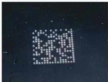
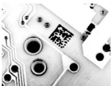
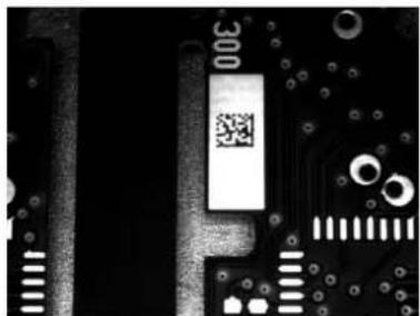
Matrix 200 ^™ is also very powerful in reading low-contrast direct part marked codes (see Figures 21, 22, 23, 24 and 25).

natural_image
Close-up of a metallic mechanical component with a small grid-like mark on its surface (no text or symbols visible)Figure 21 - Dot Matrix Code Directly Marked on Metal Surface by Using Dot Peening Technology
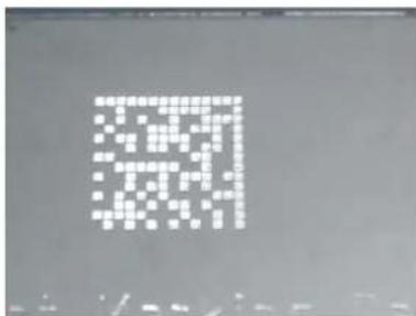
Figure 22 - Dot Peening Marking on Metal Surface with Multi-dot per Code Element
natural_image
Abstract pattern of white dots arranged in a grid on a dark background (no text or symbols)Figure 23 - Directly Marked Dot Matrix Code Characterized by Outstanding Separation Distance between Adjacent Code Elements
natural_image
Close-up of a printed circuit board with visible traces and pads (no readable text or symbols)Figure 24 - DataMatrix Code Directly Marked on PCB Surface by Using Laser Etching Technology
natural_image
Close-up of a printed circuit board with visible traces, pads, and a QR code (no readable text or symbols)Figure 25 - Dot Matrix Code Directly Marked on PCB Copper Pad by Using Ink-Jet Technology
3 INSTALLATION
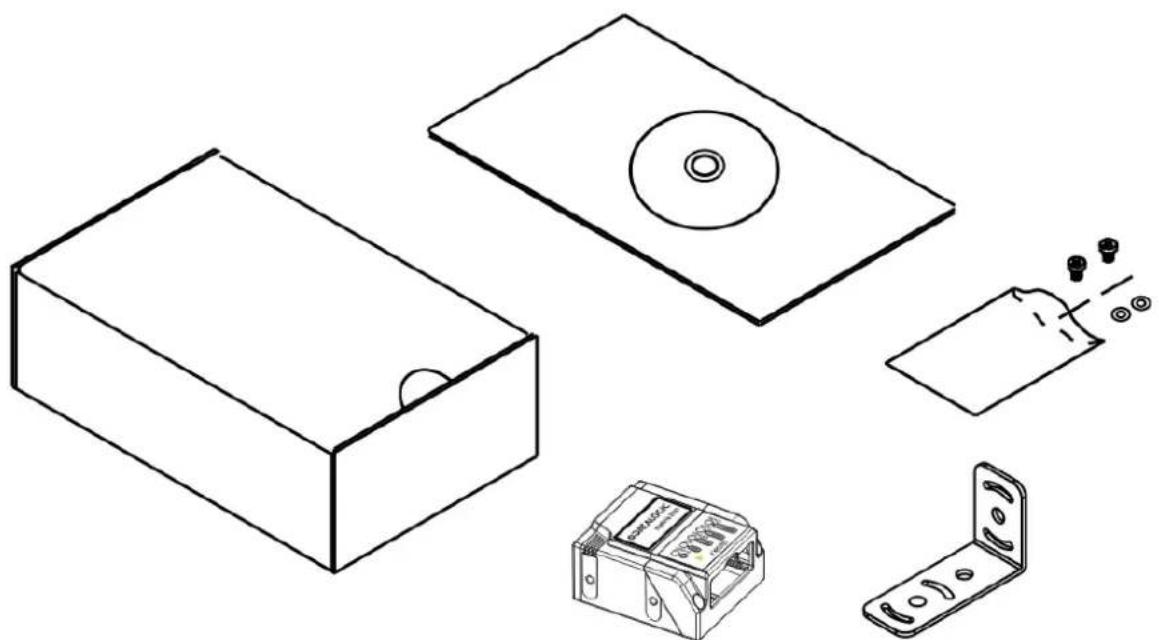
3.1 PACKAGE CONTENTS
Verify that the Matrix 200 ^™ reader and all the parts supplied with the equipment are present and intact when opening the packaging; the list of parts includes:
Matrix 200 ^TM reader
Quick Reference Guide
Test Chart
Matrix family CD-ROM
Mounting Kit
- Mounting Screws (2)
- Washers (2)
- Mounting Bracket
natural_image
Line drawings of various electronic components including a CD, box, battery, and switch (no text or symbols)Figure 26 - Package Contents
3.2 MECHANICAL DIMENSIONS
Matrix 200 ^™ can be installed to operate in different positions. The four screw holes (M3 x 4) on the body of the reader are for mechanical fixture (Figure 27).
The diagram below gives the overall dimensions of the reader and may be used for its installation.
Refer to par. 3.3 for various mounting solutions and correct positioning and chp. 7 for Reading Distance considerations.
![7 [0.28] 25 [0.98] 10 [0.39] 25 [0.98] 11 [0.43] OPTICAL AXIS M3x4 n°4](/content/2026/06/1280866/images/4b6e859b45f771351073bc37fb22ba8e1294e610d23b220cd48d3758365b9c20.jpg)
![13 [0.51] 15 [0.59] 45 [1.77]](/content/2026/06/1280866/images/0eae941babcd2d6c4230286e9074195a4b2a70a36ca71fb9104558373115b44a.jpg)
![50 [1.97]](/content/2026/06/1280866/images/00e6b847a9f264d93dc666c67fd23befbe2445353fd1603a0722561330095d51.jpg)
Figure 27 – Straight Model Overall Dimensions
mm
[in]
![M3x4 n°4 7 25 [0.98] 9 [0.35][0.28] 32 [1.26] 25 [0.98] 11 [0.43] 75° OPTICAL AXIS](/content/2026/06/1280866/images/ba43f55c72d83013718c12afa1299b8655ae4e6853511330ebff940df84f15de.jpg)
![13 [0.51] 15 [0.59] mm [in] 45 [1.77]](/content/2026/06/1280866/images/c592498f882d8304c9d67dc47c09e8d30c02979d1c6c09500480a2fcb18362b3.jpg)
![54 [2.13]](/content/2026/06/1280866/images/33ccd5b2a57d73a6495f5cccd179a6074f5c8004b886ef124cda2b7d6f534da0.jpg)
Figure 28 - 90^ Model Overall Dimensions
mm
[in]
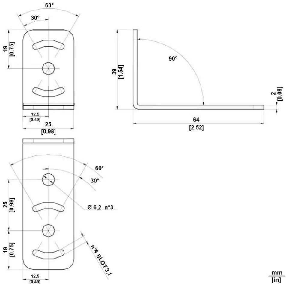
Figure 29 - ST-336 Mounting Bracket Overall Dimensions
![n°4 SLOT 3.1 10 [0.39] 30° 60° 18.5 [0.73] Ø 6.2 n°2](/content/2026/06/1280866/images/2c5627f6fcf630b3b202feac04b1f96759960aad258a690bb1396da201563409.jpg)
![22 [0.87] 38 [1.50] 2 [0.08]](/content/2026/06/1280866/images/a82d4e9a8ef2e83e02e730ebfb6372f57455b55fd74be97755daa2d9519252cb.jpg)
![37 [1.46] 30° 60° 18.5 [0.73] 10 [0.39]](/content/2026/06/1280866/images/20e44f14071edbc72092f0e62d5ed0529e8887edcf45cae37e7f616902e22b23.jpg)
Figure 30 - ST-337 Mounting Bracket Overall Dimensions
3.3 MOUNTING AND POSITIONING MATRIX 200 ^TM
Using the Matrix 200 ^™ mounting brackets you can obtain rotation on the various axes of the reader as shown in the diagrams below:
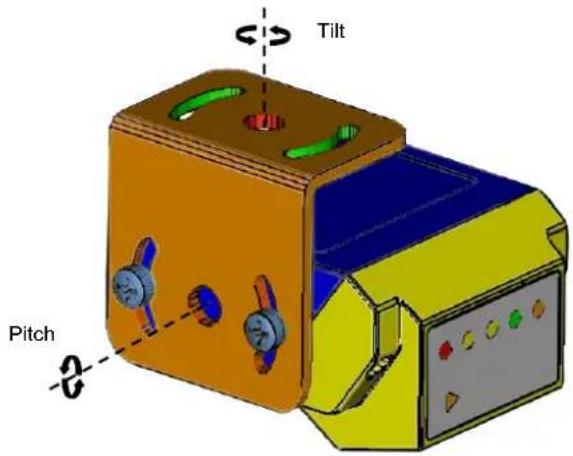
Figure 31 -90° Model with ST-337 Mounting Bracket - Internal Positioning
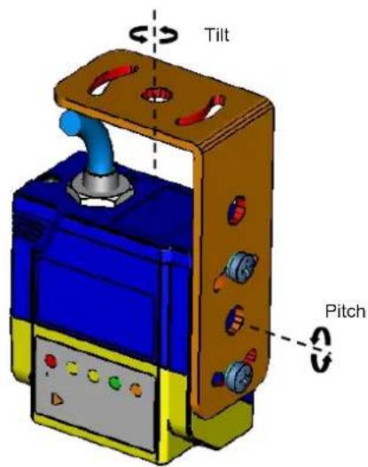
Figure 32 - Straight Model with ST-336 Mounting Bracket - Internal Positioning

natural_image
Two 3D-rendered mechanical components with colored surfaces and mounting holes, no text or symbols present.Figure 33 -Mounting Bracket External Positioning
Matrix 200 ^™ is able to decode code labels at a variety of angles, however significant angular distortion may degrade reading performance.
When mounting Matrix 200 ^™ , take into consideration these ideal label position angles: Pitch or Skew 10° to 20° and Tilt 0°.
Note: Since Matrix 200 ^™ is omni-directional on the code plane, the Pitch and Skew angles have the same significance with respect to the code plane. However in some advanced code reading applications performance can be improved by modifying the Pitch angle.
Follow the suggestions below for the best orientation:
The Pitch and Skew angles are represented by the values P and S in Figure 34 and in Figure 35. Position the reader in order to avoid the direct reflection of the light emitted by the Matrix 200 ^™ reader; it is advised to assure at least 10° for one of these angles. In some cases, such as low contrast or low illumination, it can be useful to use a Pitch or Skew angle = 0°.
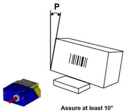
Figure 34 - Pitch angle
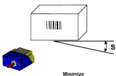
Figure 35 - Skew angle
The Tilt angle is represented by the value T in Figure 36. Matrix 200 ^™ can read labels with any tilt angle.
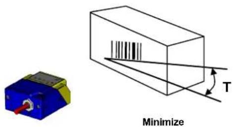
Figure 36 - Tilt angle
See chp. 7 for FOV and Reading Distance considerations.
4 CBX ELECTRICAL CONNECTIONS
All Matrix 200 ^TM 25-pin models can be directly connected to a CBX connection box.
We recommend making system connections through one of the CBX connection boxes since they offer the advantages of easy connection, easy device replacement and filtered reference signals.

NOTE
If you require direct wiring to the reader the details of the connector pins and relative connections are indicated in Chapter 5.
The table below gives the pinout of the CBX100/500 terminal block connectors. Use this pinout when the Matrix 200 ^™ reader is connected by means of the CBX100/500:
| CBX100/500 Terminal Block Connectors | |||
| Input Power | |||
| Vdc Power Supply Input Voltage + | |||
| GND Power Supply Input Voltage - | |||
| Earth Protection Earth Ground | |||
| Inputs | |||
| +V Power Source – External Trigger | |||
| I1A External Trigger A (polarity insensitive) | |||
| I1B External Trigger B (polarity insensitive) | |||
| -V Power Reference – External Trigger | |||
| +V Power Source – Inputs | |||
| I2A Input 2 A (polarity insensitive) | |||
| I2B Input 2 B (polarity insensitive) | |||
| -V Power Reference – Inputs | |||
| Outputs | |||
| +V Power Source - Outputs | |||
| -V Power Reference - Outputs | |||
| O1+ Output 1 + | |||
| O1- Output 1 - | |||
| O2+ Output 2 + | |||
| O2- Output 2 - | |||
| Auxiliary Interface | |||
| TX Auxiliary Interface TX | |||
| RX Auxiliary Interface RX | |||
| SGND Auxiliary Interface Reference | |||
| ID-NETTM | |||
| REF Network Reference | |||
| ID+ ID-NETTM network + | |||
| ID- ID-NETTM network - | |||
| Shield Network Cable Shield | |||
| Main Interface | |||
| RS232 | RS485Full-Duplex | RS485Half-Duplex | |
| TX | TX+ | ||
| RX | *RX+ | ||
| RTS | TX- | F | |
| CTS | *RX- | ||
| SGND | SGND | SGND | |
* Do not leave floating, see par. 4.2.2 for connection details.

NOTE
To avoid electromagnetic interference when the reader is connected to a CBX connection box, verify the jumper positions in the CBX as indicated in its Installation Manual.
4.1 POWER SUPPLY
Power can be supplied to the reader through the CBX100/500 spring clamp terminal pins as shown in Figure 37:
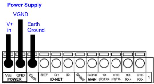
Figure 37 - Power Supply Connections
The power must be between 10 and 30 Vdc only.
It is recommended to connect the device CHASSIS to earth ground (Earth) by setting the appropriate jumper in the CBX connection box. See the CBX Installation Manual for details.
4.2 MAIN SERIAL INTERFACE
The signals relative to the following serial interface types are available on the CBX spring clamp terminal blocks.
The main serial interface type and its parameters (baud rate, data bits, etc.) can be defined by the user via VisiSet™ software. The RS485 half duplex is automatically set whenever MUX32 communication protocol is enabled. For more details refer to the "Communication" folder in the VisiSet™ Help On Line.
Details regarding the connections and use of the interfaces are given in the next paragraphs.
4.2.1 RS232 Interface
The RS232 interface can be used for Point-to-Point, Pass Through or Master/Slave connections. When it is connected to the host computer it allows both transmission of code data and reader configuration by VisiSet ^™ .
The following pins are used for RS232 interface connection:
| CBX100/500 Function | ||
| TX | Transmit | Data |
| RX | Receive | Data |
| RTS Request To Send | ||
| CTS Clear To Send | ||
| SGND | Signal | Ground |
It is always advisable to use shielded cables. The overall maximum cable length must be less than 15 m (49.2 ft).
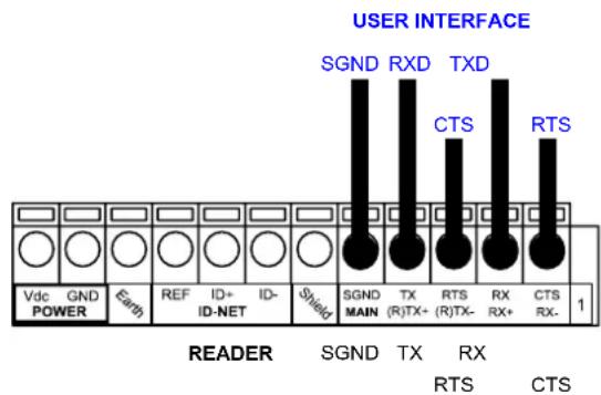
Figure 38 – RS232 Main Interface Connections Using Hardware Handshaking
The RTS and CTS signals control data transmission and synchronize the connected devices.
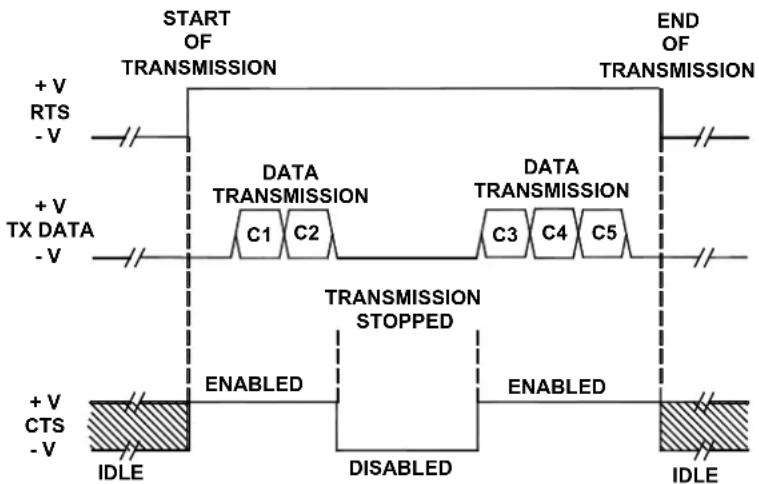
flowchart
graph TD
    A["START OF TRANSMISSION"] --> B["DATA TRANSMISSION"]
    B --> C["C1 C2"]
    B --> D["C3 C4 C5"]
    E["END OF TRANSMISSION"] --> F["DATA TRANSMISSION STOPPED"]
    F --> G["ENABLED"]
    F --> H["DISABLED"]
    I["+ V RTS - V"] --> J["+ V TX DATA - V"]
    K["+ V CTS - V"] --> L["+ V IDLE"]
    M["IDLE"] --> N["ENABLED"]
    O["IDLE"] --> P["ENABLED"]
Figure 39 - RS232 Control Signals
If the RTS/CTS handshaking protocol is enabled, the Matrix 200 ^™ activates the RTS output to indicate a message is to be transmitted. The receiving unit activates the CTS input to enable the transmission.
4.2.2 RS485 Full-Duplex Interface
The RS485 full-duplex (5 wires + shield) interface is used for non-polled communication protocols in point-to-point connections over longer distances (max 1200 m / 3940 ft) than those acceptable for RS232 communications or in electrically noisy environments.
The CBX pinout follows:
CBX100/500 Function
| TX+ | RS485 | Transmit Data + |
| RX+ | RS485 | Receive Data + |
| TX- RS485 Transmit Data - |
| RX- | RS485 | Receive Data - |
SGND
Signal
Ground
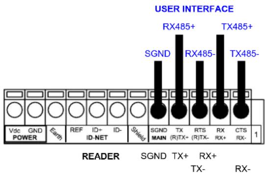
Figure 40 - RS485 Full-duplex Connections

NOTE
For applications that do not use RX485 signals, do not leave these lines floating but connect them to SGND as shown below.
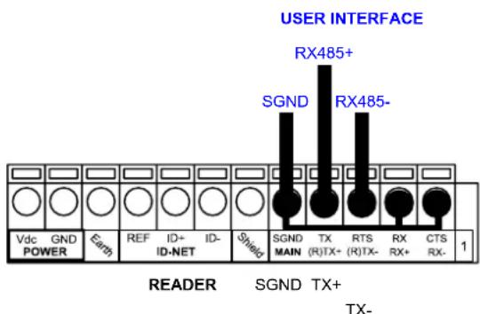
Figure 41 - RS485 Full-duplex Connections using Only TX Signals
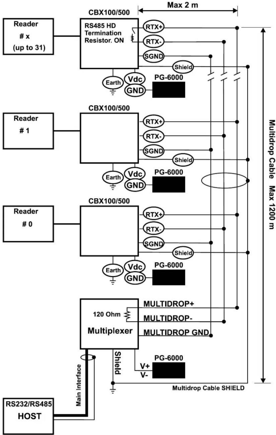
4.2.3 RS485 Half-Duplex Interface

NOTE
This interface is provided for backward compatibility. We recommend using the more efficient ID-NET ^™ network for Master/Slave or Multiplexer layouts.
The RS485 half-duplex (3 wires + shield) interface is used for polled communication protocols.
It can be used for Multidrop connections with a Datalogic Multiplexer, (see par. 6.5) exploiting a proprietary protocol based on polled mode called MUX32 protocol, where a master device polls slave devices to collect data.
CBX100/500 Function
| RTX+ | RS485 Receive/Transmit Data + | |
| RTX- | RS485 Receive/Transmit Data - | |
| SGND | Signal | Ground |
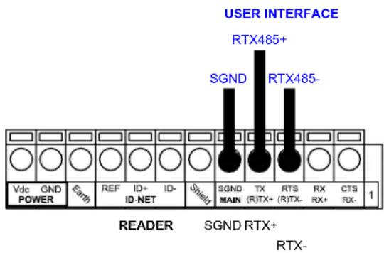
Figure 42 - RS485 Half-duplex Connections
This interface is forced by software when the protocol selected is MUX32 protocol.
In a Multiplexer layout, the Multidrop address must also be set via serial channel by the VisiSet ^™ utility or by the Host Programming Mode.
Figure 43 shows a multidrop configuration with Matrix 200 ^TM readers connected to a Multiplexer.

CAUTION
This is an example of multidrop wiring. Consult the multiplexer manual for complete wiring instructions.
flowchart
graph TD
    A["Reader # x (up to 31)"] --> B["RS485 HD Termination Resistor. ON"]
    B --> C["Max 2 m"]
    B --> D["PG-6000"]
    B --> E["Vdc GND"]
    E --> F[" readers # 1"]
    B --> G["PG-6000"]
    H["Reader # 0"] --> I["CBX100/500"]
    I --> J["Max 2 m"]
    I --> K["PG-6000"]
    I --> L["Vdc GND"]
    L --> M[" readers # 0"]
    I --> N["PG-6000"]
    O["120 Ohm Multiplexer"] --> P["MULTIDROP+ MULTIDROP- MULTIDROP GND"]
    P --> Q["Multidrop Cable SHIELD"]
    R["RS232/RS485 HOST"] --> S["Main Interface"]
    S --> T["Shield"]
    T --> U["V+ V-"]
    U --> V["Multidrop Cable SHIELD"]
Figure 43 - Matrix 200™ Multidrop Connection to a Multiplexer
The following instructions are referred to Figure 45, Figure 46 and Figure 47.
- The general cable type specifications are: CAT5 twisted pair + additional CAT5 twisted pair, shielded cable AWG 24 (or AWG 22) stranded flexible.
We recommend using DeviceNet cables (drop or trunk type) to the following reference standards:
AN50325 - IEC 62026
UL STYLE 2502 80°C 30V
- Cable Shield MUST be connected to earth ground ONLY at the Master.
- NEVER use ID-NET™ cable shield as common reference.
- The ID-NET ^™ max cable length depends on the baudrate used, (see the Baudrate Table below).
-
For Common Power Connections use only 2 wires (ID+ and ID-).
-
DC Voltage Power cable (Vdc – GND) should be handled as a signal cable (i.e. do not put it together with AC cable):
- Wire dimensioning must be checked in order to avoid voltage drops greater than 0.8 Volts.
-
Cable should lie down as near as possible to the ID-NET™ cable (avoiding wide loops between them).
-
Reader's chassis may be connected to earth.
• Network inside the same building.
| Baudrate Table | ||||
| Baud Rate 125 kbps | 250 kbps | 500 kbps | 1Mbps | |
| Cable Length 1200 m | 900 m | 700 m | * | |
* Application dependent, contact your Datalogic Automation representative for details.

NOTE
The default ID-NET ^™ baudrate is 500 kbps. Lower ID-NET ^™ baudrates allow longer cable lengths. The baudrate is software configurable by authorized Datalogic Automation personnel only.
The following figure shows the response time of the ID-NET ^™ network. This time is defined as the period between the Trigger activation and the beginning of data transmission to the Host.
Figure 45 – ID-NET™ Network Connections with isolated power blocks
flowchart
graph TD
    A["Reader Slave (up to 31)"] --> B["CBX100/500"]
    B --> C["ID-NET™ Termination Resistor. ON"]
    C --> D["ID+"]
    C --> E["ID-"]
    C --> F["Shield"]
    B --> G["CBX100/500"]
    G --> H["ID+"]
    G --> I["ID-"]
    G --> J["Shield"]
    B --> K["CBX100/500"]
    K --> L["ID+"]
    K --> M["ID-"]
    K --> N["Shield"]
    B --> O["CBX100/500"]
    O --> P["ID-NET™ Termination Resistor. ON"]
    P --> Q["ID+ (white)"]
    P --> R["ID- (blue)"]
    P --> S["Shield"]
    O --> T["RS232/RS485 HOST"]
    T --> U["Main Interface"]
    U --> V["Vdc GND POWER"]
    U --> W["Vdc GND GND"]
    W --> X["Reader Master"]
    X --> Y["12-24 Vdc"]
    Y --> Z["Reader Slave"]
    Z --> AA["CBX100/500"]
    AA --> AB["Max 0.3 m"]
    AA --> AC["* Refer to Baudrate Table for max length"]
Figure 46 - ID-NET™ Network Connections with Common Power Branch Network
flowchart
graph TD
    A["Reader Slave (up to 31)"] --> B["CBX100/500"]
    B --> C["ID-NET™ Termination Resistor. ON"]
    C --> D["ID+"]
    C --> E["ID-"]
    C --> F["Shield"]
    B --> G["CBX100/500"]
    G --> H["ID+"]
    G --> I["ID-"]
    G --> J["Shield"]
    B --> K["CBX100/500"]
    K --> L["ID+"]
    K --> M["ID-"]
    K --> N["Shield"]
    B --> O["CBX100/500"]
    O --> P["ID-NET™ Termination Resistor. ON"]
    P --> Q["ID+ (white)"]
    P --> R["ID- (blue)"]
    P --> S["Shield"]
    O --> T["Vdc GND POWER"]
    O --> U["RS232/RS485 HOST"]
    O --> V["Main Interface"]
    V --> W["Earth"]
    B --> X["Max 0.3 m"]
    X --> Y["* Refer to Baudrate Table for max length"]
Figure 47 – ID-NET™ Network Connections with Common Power Star Network
The network must be properly terminated in the first and last reader of the network. This is done by setting the ID-NET ^™ Termination Resistance Switch in the CBX100/500 to ON.
4.4 AUXILIARY RS232 INTERFACE
The RS232 auxiliary interface is available for Point-to-Point, Pass Through or Master/Slave connections. When it is connected to the host computer it allows both transmission of code data and reader configuration by VisiSet ^™ .
The parameters relative to the aux interface (baud rate, data bits, etc.) as well as particular communication modes such as LOCAL ECHO can be defined through the Communication folder of the VisiSet ^™ utility program.
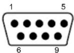
The 9-pin female Auxiliary Interface connector inside the CBX is the preferred connector for device configuration or communication monitoring.
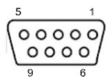
Figure 48 - 9-pin female connector
If permanent system wiring is required, the following pins are used to connect the RS232 auxiliary interface:
| CBX100/500 Function |
| RX Auxiliary Interface Receive Data |
| TX Auxiliary Interface Transmit Data |
| SGND Auxiliary Interface Reference |
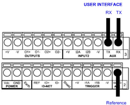
Figure 49 - RS232 Auxiliary Interface Connections

NOTE
Do not connect the Aux Interface to the CBX spring clamp connectors and the 9-pin connector simultaneously.
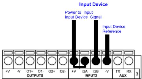
4.5 INPUTS
There are two optocoupled polarity insensitive inputs available on the reader: Input 1 (External Trigger) and Input 2, a generic input:
The External Trigger can be used in One Shot Mode or in Phase Mode. Its main functions are:
• acquisition trigger in One Shot Mode
- reading phase-ON/reading phase-OFF command in Phase Mode
The main functions of the general purpose Input 2 are:
• second external trigger in Phase Mode
- match code storage command when the Match Code option is enabled
The electrical features of both inputs are:
$$ V _ {A B} = 3 0 \mathrm{Vdc} \max. $$
$$ I _ {I N} = 1 2 \mathrm{mA} (\text { reader }) + 1 2 \mathrm{mA} (\text { CBX }) \max. $$
The active state of these inputs are selected in software. Refer to the VisiSet ^™ Help On Line.
An anti-disturbance filter is implemented in software on both inputs so that the minimum pulse duration is 0.5 milliseconds. This value can be increased through the software parameter Debounce Filter, see the Digital I/O folder in the VisiSet ^™ Help On Line for further details.
These inputs are optocoupled and can be driven by both NPN and PNP type commands.

NOTE
Polarity insensitive inputs assure full functionality even if pins A and B are exchanged.
The connections are indicated in the following diagrams:
CBX100/500 Function
+V Power Source - External Trigger
I1A External Trigger A (polarity insensitive)
I1B External Trigger B (polarity insensitive)
-V Power Reference - External Trigger
The yellow Trigger LED (Figure 16, 5) is on when the active state of the External Trigger corresponds to ON.
EXTERNAL TRIGGER INPUT CONNECTIONS USING MATRIX 200™ POWER

CAUTION
Power is available directly to the Input Device, independently from the Power Supply Switch inside the CBX.
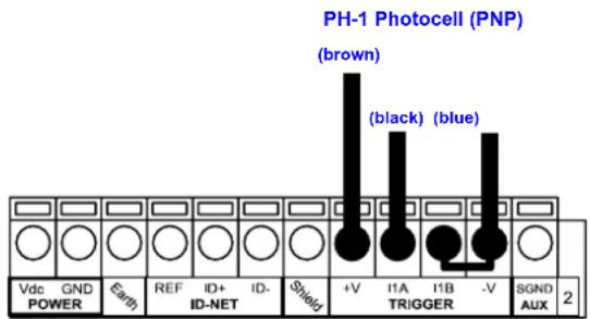
Figure 50 – PH-1 External Trigger Using Matrix 200™ Power
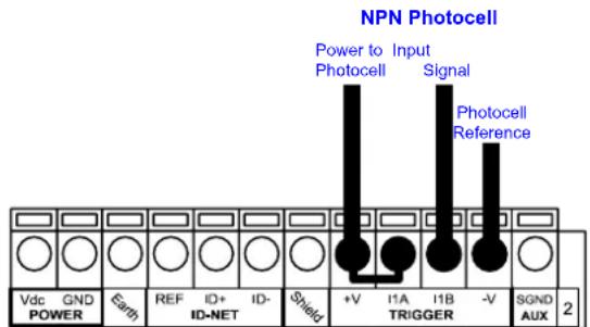
Figure 51 - NPN External Trigger Using Matrix 200™ Power
EXTERNAL TRIGGER INPUT CONNECTIONS USING EXTERNAL POWER
Figure 52 - PNP External Trigger Using External Power
Figure 53 - NPN External Trigger Using External Power
CBX100/500 Function
+V Power Source - Inputs
I2A Input 2 A (polarity insensitive)
I2B Input 2 B (polarity insensitive)
-V Power Reference - Inputs
INPUT 2 CONNECTIONS USING MATRIX 200 ^TM POWER

CAUTION
Power is available directly to the Input Device, independently from the Power Supply Switch inside the CBX.
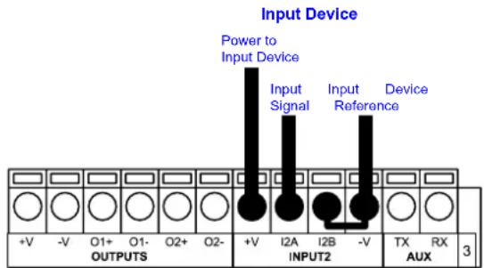
PNP Input 2 Using Matrix 200 ^TM Power
NPN Input 2 Using Matrix 200 ^TM Power
INPUT 2 CONNECTIONS USING EXTERNAL POWER
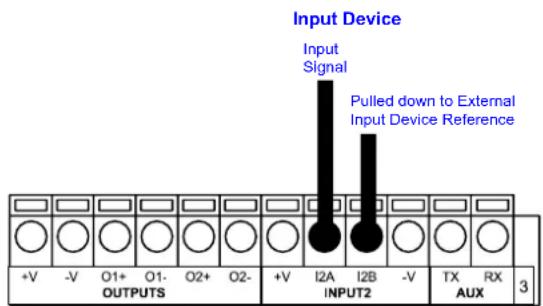
Figure 54 - PNP Input 2 Using External Power
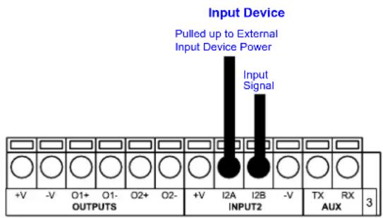
Figure 55 - NPN Input 2 Using External Power
4.6 OUTPUTS
Two optocoupled general purpose outputs are available. The meaning of the two outputs Output 1 and Output 2 can be defined by the user. They are typically used either to signal the data collection result or to control an external lighting system.
| CBX100/500 Function | |
| +V Power Source | - Outputs |
| O1+ Output 1 + | |
| O1- Output 1 - | |
| O2+ Output 2 + | |
| O2- Output 2 - | |
| -V Power Reference Outputs | |
The electrical features of the two outputs are the following:
$$ V _ {C E} = 3 0 \mathrm{Vdc} \max. $$
$$ I _ {C E} = 4 0 \mathrm{mA} \text { continuous max. }; 1 3 0 \mathrm{mA} \text { pulsed max. } $$
By default, Output 1 is associated with the Partial Read and No Read events, which activates when the code(s) signaled by the external trigger are not decoded, and Output 2 is associated with the Complete Read event, which activates when all the selected codes are correctly decoded.
The output signals are fully programmable being determined by the configured Activation/Deactivation events, Deactivation Timeout or a combination of the two. Refer to the Digital I/O folder in the VisiSet™ Help On Line for further details.
OUTPUT CONNECTIONS USING MATRIX 200™ POWER

CAUTION
Power is available directly to the Output Device, independently from the Power Supply Switch inside the CBX.
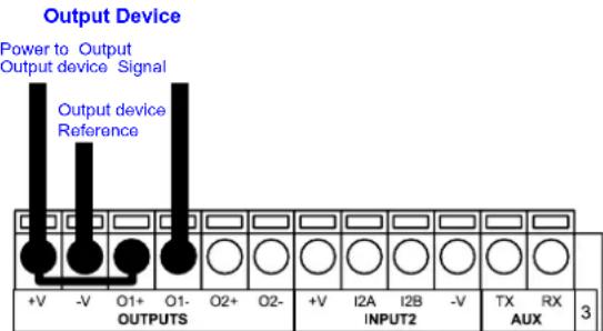
Figure 56 - Open Emitter Output Using Matrix 200™ Power
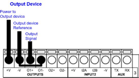
Figure 57 - Open Collector Output Using Matrix 200 ^TM Power
OUTPUT CONNECTIONS USING EXTERNAL POWER
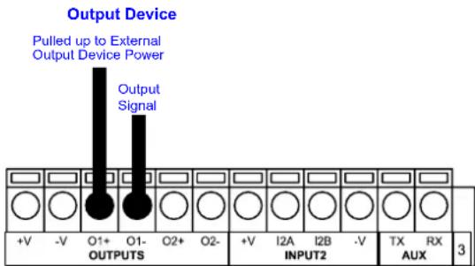
Figure 58 - Output Open Emitter Using External Power
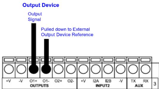
Figure 59 - Output Open Collector Using External Power
4.7 USER INTERFACE - HOST
The following table contains the pinout for standard RS232 PC Host interface. For other user interface types please refer to their own manual.
| RS232 PC-side connections | |||
 9-pin male connector 9-pin male connector | 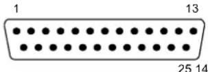 25-pin male connector 25-pin male connector | ||
| Pin | Name | Pin | Name |
| 2 | RX | 3 | RX |
| 3 | TX | 2 | TX |
| 5 | GND | 7 | GND |
| 7 | RTS | 4 | RTS |
| 8 | CTS | 5 | CTS |
5 25-PIN CABLE ELECTRICAL CONNECTIONS
5.1 25-PIN CONNECTOR
The Matrix 200 ^™ reader is equipped with a 25-pin male D-sub connector for connection to the power supply, serial interfaces and input/output signals. The details of the connector pins are indicated in the following table:
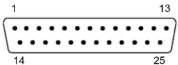
Figure 60 - 25-pin Male D-sub Connector
| 25-pin D-sub male connector pinout | ||||
| Pin | Name | Function | ||
| 13, 9 Vdc | Power supply input voltage + | |||
| 25, 7 GND | Power supply input voltage - | |||
| 1 CHAS | SIS Cable shield connected to chassis | |||
| 18 I1A | External Trigger A (polarity insensitive) | |||
| 19 I1B | External Trigger B (polarity insensitive) | |||
| 6 I2A | Input 2 A (polarity insensitive) | |||
| 10 I2B | Input 2 B (polarity insensitive) | |||
| 8 O1+ | Output 1 + | |||
| 22 O1- | Output 1 - | |||
| 11 O2+ | Output 2 + | |||
| 12 O2- | Output 2 - | |||
| 20 RX | Auxiliary RS232 RX | |||
| 21 TX | Auxiliary RS232 TX | |||
| 23 | ID+ | ID-NETTM network + | ||
| 24 | ID- | ID-NETTM network - | ||
| 14, 15, 16, 17 | NC | Not Connected | ||
| Pin | Name | RS232 | RS485Full-Duplex | RS485Half-Duplex |
| 2 | TX | TX+ | RTX+ | |
| 3 | MAIN INTERFACE(SW SELECTABLE) | RX | *RX+ | |
| 4 | RTS | TX- | RTX- | |
| 5 | CTS | *RX- | ||
* Do not leave floating, see par. 5.3.2 for connection details.
In order to meet EMC requirements:
- connect the reader chassis to the plant earth ground by means of a flat copper braid shorter than 100 mm;
- for direct connections, connect the main interface cable shield to pin 1 of the 25-pin connector.
5.2 POWER SUPPLY
Power is supplied to the reader through the pins provided on the 25-pin connector (see Figure 61):
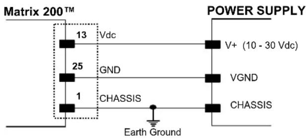
Figure 61 - Power Supply Connection
The allowed supply voltage range is 10 to 30 Vdc.
It is recommended to connect pin 1 (CHASSIS) to a common earth ground.
5.3 MAIN SERIAL INTERFACE
The signals relative to the following serial interface types are available on the 25-pin connector:
The main serial interface type and its parameters (baud rate, data bits, etc.) can be defined by the user via VisiSet™ software. The RS485 half duplex is automatically set whenever MUX32 communication protocol is enabled. For more details refer to the "Communication" folder in the VisiSet™ Help On Line.
Details regarding the connections and use of the interfaces are given in the next paragraphs.
5.3.1 RS232 Interface
The RS232 interface can be used for Point-to-Point, Pass Through or Master/Slave connections. When it is connected to the host computer it allows both transmission of code data and reader configuration by VisiSet ^™ .
The following pins of the 25-pin connector are used for RS232 interface connection:
| Pin | Name | Function | |
| 2 | TX | Transmit | Data |
| 3 | RX | Receive | Data |
| 4 | RTS Request To Send | ||
| 5 | CTS Clear To Send | ||
| 7 | GND | Ground | |
It is always advisable to use shielded cables. The overall maximum cable length must be less than 15 m (49.2 ft).
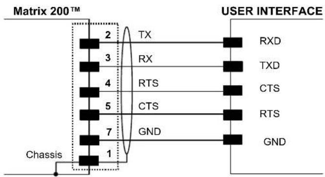
Figure 62 - RS232 Main Interface Connections Using Hardware Handshaking
The RTS and CTS signals control data transmission and synchronize the connected devices.
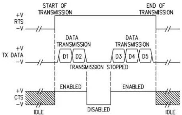
flowchart
graph TD
    A["START OF TRANSMISSION"] --> B["DATA TRANSMISSION"]
    B --> C["TRANSMISSION STOPPED"]
    C --> D["IDLE"]
    E["END OF TRANSMISSION"] --> F["DATA TRANSMISSION"]
    F --> G["TRANSMISSION STOPPED"]
    G --> H["IDLE"]
    I["+V RTS -V"] --> J["+V TX DATA -V"]
    K["+V CTS -V"] --> L["+V CTS IDLE"]
    M["DISABLED"] --> N["ENABLED"]
    O["ENABLED"] --> P["ENABLED"]
    Q["END"] --> R["IDLE"]
Figure 63 - RS232 Control Signals
If the RTS/CTS handshaking protocol is enabled, Matrix 200 ^™ activates the RTS output to indicate a message is to be transmitted. The receiving unit activates the CTS input to enable the transmission.
5.3.2 RS485 Full-Duplex Interface
The RS485 full-duplex (5 wires + shield) interface is used for non-polled communication protocols in point-to-point connections over longer distances (max 1200 m / 3940 ft) than those acceptable for RS232 communications or in electrically noisy environments.
The following pins of the 25-pin connector are used for RS485 full-duplex communication:
| Pin | Name | Function |
| 2 TX+ | RS485 | Transmit Data (+) |
| 3 RX+ | RS485 | Receive Data (+) |
| 4 TX- | RS485 | Transmit Data (-) |
| 5 RX- | RS485 | Receive Data (-) |
| 7 | GND | Ground |
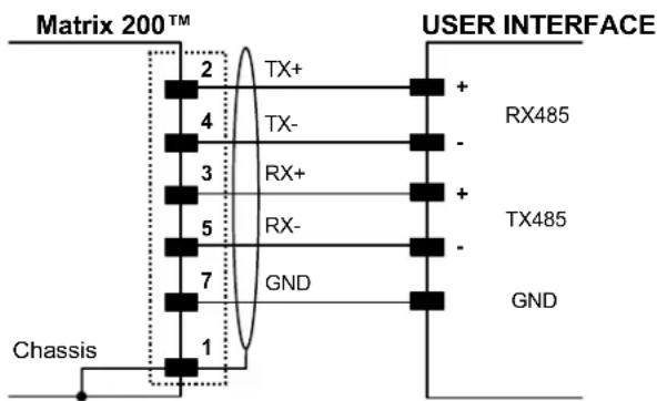
Figure 64 - RS485 Full-duplex Connections

NOTE
For applications that do not use RX485 signals, do not leave these lines floating but connect them to GND as shown below.
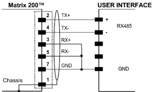
Figure 65 - RS485 Full-duplex Connections using Only TX Signals
5.3.3 RS485 Half-Duplex Interface

NOTE
This interface is provided for backward compatibility. We recommend using the more efficient ID-NET ^™ network for Master/Slave or Multiplexer layouts.
The RS485 half-duplex (3 wires + shield) interface is available for polled communication protocols.
It can be used for Multidrop connections with a Datalogic Multiplexer, (see par. 6.5) exploiting a proprietary protocol based on polled mode called MUX32 protocol, where a master device polls slave devices to collect data.
The following pins of the 25-pin connector are used for RS485 half-duplex communication:
| Pin | Name | Function |
| 2 | RTX+ RS485 | Receive/Transmit Data (+) |
| 4 | RTX- RS485 | Receive/Transmit Data (-) |
| 7 | GND | Ground |
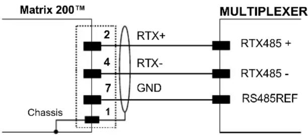
Figure 66 - RS485 Half-duplex Connections
This interface is forced by software when the protocol selected is MUX32 protocol.
In a Multiplexer layout, the Multidrop address must also be set via serial channel by the VisiSet ^™ utility or by the Host Programming Mode.
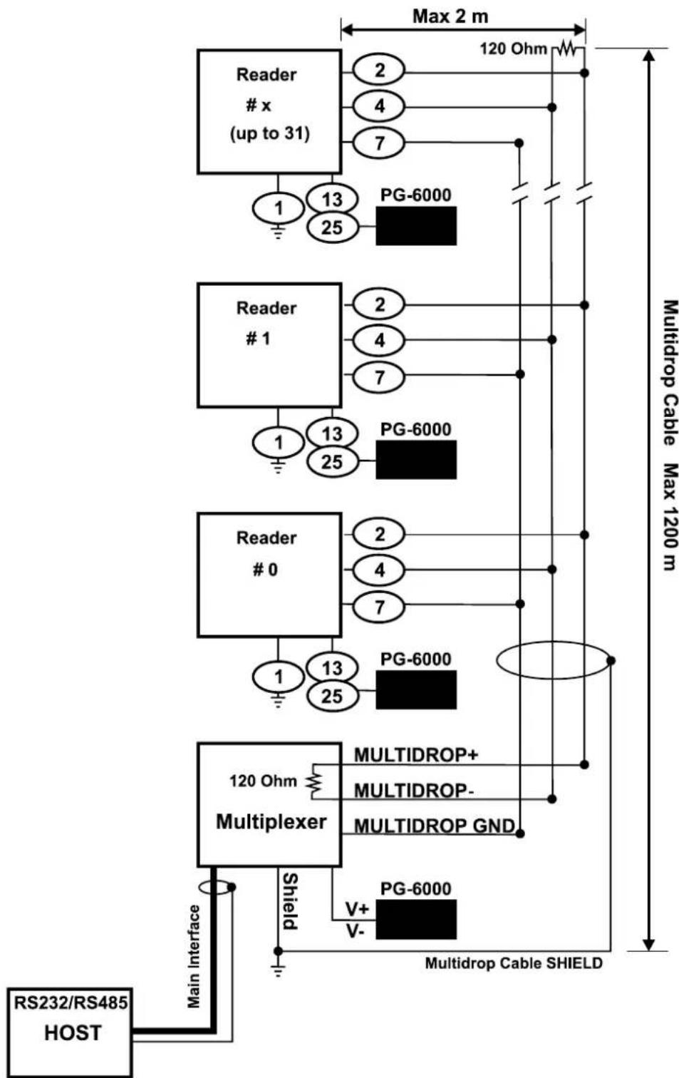
The figure below shows a multidrop configuration with Matrix 200 ^™ readers connected to a Multiplexer.

This is an example of multidrop wiring. Consult the multiplexer manual for complete wiring instructions.
flowchart
graph TD
    A["RS232/RS485 HOST"] --> B["Main Interface"]
    B --> C["Multiplexer"]
    C --> D["120 Ohm"]
    D --> E["MULTIDROP+"]
    D --> F["MULTIDROP-"]
    D --> G["MULTIDROP GND"]
    C --> H["PG-6000"]
    C --> I["PG-6000"]
    C --> J["PG-6000"]
    C --> K["PG-6000"]
    C --> L["PG-6000"]
    C --> M["PG-6000"]
    C --> N["PG-6000"]
    C --> O["PG-6000"]
    C --> P["PG-6000"]
    C --> Q["PG-6000"]
    C --> R["PG-6000"]
    C --> S["PG-6000"]
    C --> T["PG-6000"]
    C --> U["PG-6000"]
    C --> V["PG-6000"]
    C --> W["PG-6000"]
    C --> X["PG-6000"]
    C --> Y["PG-6000"]
    C --> Z["PG-6000"]
    C --> AA["PG-6000"]
    C --> AB["PG-6000"]
    C --> AC["PG-6000"]
    C --> AD["PG-6000"]
    C --> AE["PG-6000"]
    C --> AF["PG-6000"]
    C --> AG["PG-6000"]
    C --> AH["PG-6000"]
    C --> AI["PG-6000"]
    C --> AJ["PG-6000"]
    C --> AK["PG-6000"]
    C --> AL["PG-6000"]
    C --> AM["PG-6000"]
    C --> AN["PG-6000"]
    C --> AO["PG-6000"]
    C --> AP["PG-6000"]
    C --> AQ["PG-6000"]
    C --> AR["PG-6000"]
    C --> AS["PG-6000"]
    C --> AT["PG-6000"]
    C --> AU["PG-6000"]
    C --> AV["PG-6000"]
    C --> AW["PG-6000"]
    C --> AX["PG-6000"]
    C --> AY["PG-6000"]
    C --> AZ["PG-6000"]
    C --> BA["PG-6000"]
    C --> BB["PG-6000"]
    C --> BC["PG-6000"]
    C --> BD["PG-6000"]
    C --> BE["PG-6000"]
    C --> BF["PG-6000"]
    C --> BG["PG-6000"]
    C --> BH["PG-6000"]
    C --> BI["PG-6000"]
    C --> BJ["PG-6000"]
    C --> BK["PG-6000"]
    C --> BL["PG-6000"]
    C --> BM["PG-6000"]
    C --> BN["PG-6000"]
    C --> BO["PG-6000"]
    C --> BP["PG-6000"]
    C --> BQ["PG-6000"]
    C --> BR["PG-6000"]
    C --> BS["PG-6000"]
    C --> BT["PG-6000"]
    C --> BU["PG-6000"]
    C --> BV["PG-6000"]
    C --> BW["PG-6000"]
Figure 67 - Matrix 200^TM Multidrop Connection to a Multiplexer
The following instructions are referred to Figure 69, Figure 70 and Figure 71.
- The general cable type specifications are: CAT5 twisted pair + additional CAT5 twisted pair, shielded cable AWG 24 (or AWG 22) stranded flexible.
We recommend using DeviceNet cables (drop or trunk type) to the following reference standards:
AN50325 - IEC 62026
UL STYLE 2502 80°C 30V
- Cable Shield MUST be connected to earth ground ONLY at the Master.
- NEVER use ID-NET™ cable shield as common reference.
- The ID-NET ^™ max cable length depends on the baudrate used, (see the Baudrate Table below).
-
For Common Power Connections use only 2 wires (23 and 24).
-
DC Voltage Power cable (Vdc - GND) should be handled as a signal cable (i.e. do not put it together with AC cable):
- Wire dimensioning must be checked in order to avoid voltage drops greater than 0.8 Volts.
-
Cable should lie down as near as possible to the ID-NET ^™ cable (avoiding wide loops between them).
-
Reader's chassis may be connected to earth.
• Network inside the same building.
| Baudrate Table | ||||
| Baud Rate 125 kbps | 250 kbps | 500 kbps | 1Mbps | |
| Cable Length 1200 m | 900 m | 700 m | * | |
* Application dependent, contact your Datalogic Automation representative for details.

NOTE
The default ID-NET ^™ baudrate is 500 kbps. Lower ID-NET ^™ baudrates allow longer cable lengths. The baudrate is software configurable by authorized Datalogic Automation personnel only.
The following figure shows the response time of the ID-NET ^™ network. This time is defined as the period between the Trigger activation and the beginning of data transmission to the Host.
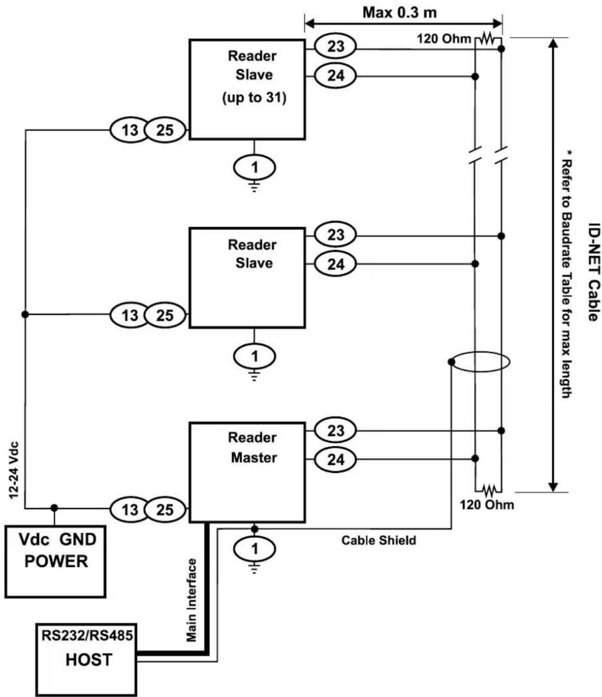
Figure 69 – ID-NET™ Network Connections with isolated power blocks
flowchart
graph TD
    A["RS232/RS485 HOST"] -->|Main Interface| B["Reader Master"]
    B -->|Cable Shield| C["Reader Slave (up to 31)"]
    C -->|Max 0.3 m| D["ID-NET Cable"]
    D -->|120 Ohm| E["120 Ohm"]
    C -->|13 25| F["13 25"]
    C -->|1| G["1"]
    B -->|13 25| H["13 25"]
    B -->|1| I["1"]
    C -->|23 24| J["23 24"]
    C -->|23 24| K["23 24"]
    B -->|23 24| L["23 24"]
    B -->|120 Ohm| M["120 Ohm"]
    style A fill:#f9f,stroke:#333
    style B fill:#ccf,stroke:#333
    style C fill:#cfc,stroke:#333
    style D fill:#fcc,stroke:#333
    style E fill:#ffc,stroke:#333
    style F fill:#fcc,stroke:#333
    style G fill:#fcc,stroke:#333
    style H fill:#fcc,stroke:#333
    style I fill:#fcc,stroke:#333
    style J fill:#fcc,stroke:#333
    style K fill:#fcc,stroke:#333
    style L fill:#fcc,stroke:#333
    style M fill:#fcc,stroke:#333
Figure 70 - ID-NET™ Network Connections with Common Power Branch Network
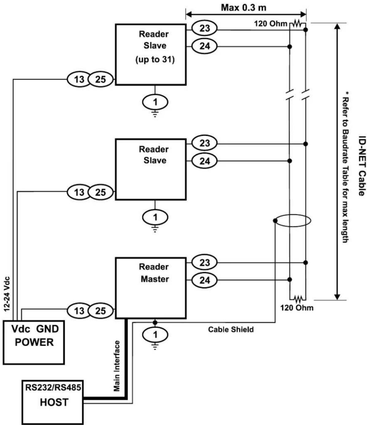
flowchart
graph TD
    A["RS232/RS485 HOST"] -->|Main Interface| B["Vdc GND POWER"]
    B --> C["Reader Master"]
    C --> D["Reader Slave (up to 31)"]
    D --> E["120 Ohm"]
    D --> F["120 Ohm"]
    D --> G["120 Ohm"]
    D --> H["120 Ohm"]
    D --> I["120 Ohm"]
    D --> J["120 Ohm"]
    D --> K["120 Ohm"]
    D --> L["120 Ohm"]
    D --> M["120 Ohm"]
    D --> N["120 Ohm"]
    D --> O["120 Ohm"]
    D --> P["120 Ohm"]
    D --> Q["120 Ohm"]
    D --> R["120 Ohm"]
    D --> S["120 Ohm"]
    D --> T["120 Ohm"]
    D --> U["120 Ohm"]
    D --> V["120 Ohm"]
    D --> W["120 Ohm"]
    D --> X["120 Ohm"]
    D --> Y["120 Ohm"]
    D --> Z["120 Ohm"]
    D --> AA["120 Ohm"]
    D --> AB["120 Ohm"]
    D --> AC["120 Ohm"]
    D --> AD["120 Ohm"]
    D --> AE["120 Ohm"]
    D --> AF["120 Ohm"]
    D --> AG["120 Ohm"]
    D --> AH["120 Ohm"]
    D --> AI["120 Ohm"]
    D --> AJ["120 Ohm"]
    D --> AK["120 Ohm"]
    D --> AL["120 Ohm"]
    D --> AM["120 Ohm"]
    D --> AN["120 Ohm"]
    D --> AO["120 Ohm"]
    D --> AP["120 Ohm"]
    D --> AQ["120 Ohm"]
    D --> AR["120 Ohm"]
    D --> AS["120 Ohm"]
    D --> AT["120 Ohm"]
    D --> AU["120 Ohm"]
    D --> AV["120 Ohm"]
    D --> AW["120 Ohm"]
    D --> AX["120 Ohm"]
    D --> AY["120 Ohm"]
    D --> AZ["120 Ohm"]
    D --> BA["120 Ohm"]
    D --> BB["120 Ohm"]
    D --> BC["120 Ohm"]
    D --> BD["120 Ohm"]
    D --> BE["120 Ohm"]
    D --> BF["120 Ohm"]
    D --> BG["120 Ohm"]
    D --> BH["120 Ohm"]
    D --> BI["120 Ohm"]
    D --> BJ["120 Ohm"]
    D --> BK["120 Ohm"]
    D --> BL["120 Ohm"]
    D --> BM["120 Ohm"]
    D --> BN["120 Ohm"]
    D --> BO["120 Ohm"]
    D --> BP["120 Ohm"]
    D --> BQ["120 Ohm"]
Figure 71 – ID-NET™ Network Connections with Common Power Star Network
The network must be properly terminated by a 120 Ohm resistor at the first and last reader of the network.
5.5 AUXILIARY RS232 INTERFACE
The RS232 auxiliary interface is available for Point-to-Point, Pass Through or Master/Slave connections. When it is connected to the host computer it allows both transmission of code data and reader configuration by VisiSet ^™ .
The parameters relative to the aux interface (baud rate, data bits, etc.) as well as particular communication modes such as LOCAL ECHO can be defined through the Communication folder of the VisiSet ^™ utility program.
The following pins of the 25-pin connector are used for auxiliary interface communication:
| Pin | Name | Function | |
| 20 | RX | Received | data |
| 21 | TX | Transmitted | data |
| 7 | GND | Ground | |
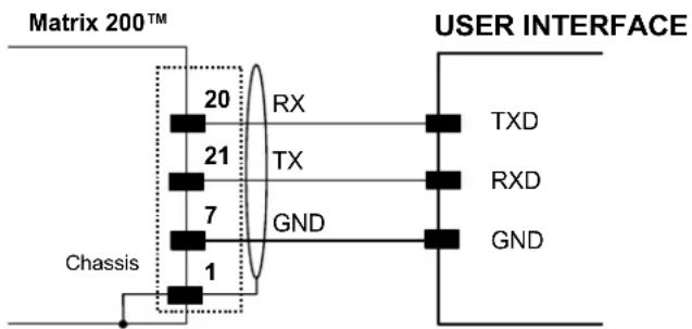
Figure 72 - RS232 Auxiliary Interface Connections Using
5.6 INPUTS
There are two optocoupled polarity insensitive inputs available on the 25-pin connector of the reader: Input 1 (External Trigger) and Input 2, a generic input:
The External Trigger can be used in One Shot Mode or in Phase Mode. Its main functions are:
• acquisition trigger in One Shot Mode
- reading phase-ON/reading phase-OFF command in Phase Mode
The main functions of the general purpose Input 2 are:
• second external trigger in Phase Mode
- match code storage command when the Match Code option is enabled
The electrical features of both inputs are:
Maximum voltage: 30 Vdc
Maximum current: 12 mA
The active state of these inputs are selected in software. Refer to the VisiSet ^™ Help On Line.
An anti-disturbance filter is implemented in software on both inputs so that the minimum pulse duration is 0.5 milliseconds. This value can be increased through the software parameter Debounce Filter, see the Digital I/O folder in the VisiSet ^™ Help On Line for further details.
These inputs are optocoupled and can be driven by both NPN and PNP type commands.

NOTE
Polarity insensitive inputs assure full functionality even if pins A and B are exchanged.
The connections are indicated in the following diagrams:
| Pin | Name | Function |
| 9 Vdc | Power Supply | input voltage + |
| 18 I1 | A External Trigger | A (polarity insensitive) |
| 19 I1 | B External Trigger | B (polarity insensitive) |
| 7 GND | Power Supply | input voltage - |
The yellow Trigger LED (Figure 16, 5) is on when the active state of the External Trigger corresponds to ON.
EXTERNAL TRIGGER INPUT PNP PH-1
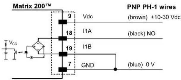
Figure 73 - PH-1 Photocell (PNP) External Trigger Using Matrix 200™ Power
EXTERNAL TRIGGER INPUT CONNECTIONS USING MATRIX 200™ POWER
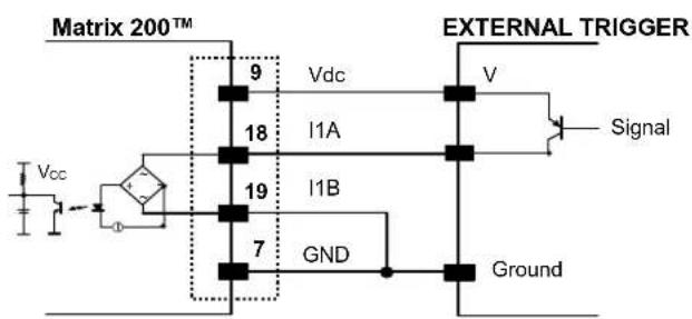
Figure 74 – PNP External Trigger Using Matrix 200™ Power
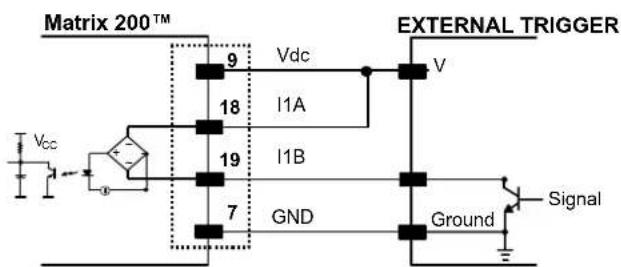
Figure 75 - NPN External Trigger Using Matrix 200™ Power
EXTERNAL TRIGGER INPUT CONNECTIONS USING EXTERNAL POWER
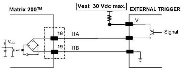
Figure 76 - PNP External Trigger Using External Power
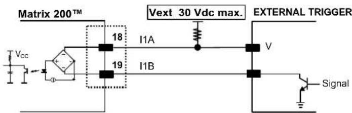
Figure 77 - NPN External Trigger Using External Power
| Pin | Name | Function |
| 9 Vdc | Power Supply | input voltage + |
| 6 I2A | Input 2 A (polarity insensitive) | |
| 10 I2B | Input 2 B (polarity insensitive) | |
| 7 GND | Power Supply | input voltage - |
INPUT 2 CONNECTIONS USING MATRIX 200™ POWER
Figure 78 - PNP Input 2 Using Matrix 200 ^TM Power

Figure 79 - NPN Input 2 Using Matrix 200 ^TM Power
INPUT 2 CONNECTIONS USING EXTERNAL POWER
Figure 80 - PNP Input 2 Using External Power
Figure 81 - NPN Input 2 Using External Power
5.7 OUTPUTS
Two opto-coupled general purpose outputs are available on the 25-pin connector. The meaning of the two outputs Output 1 and Output 2 can be defined by the user. They are typically used either to signal the data collection result.
The pinout is the following:
| Pin | Name | Function |
| 9 Vdc Power Supply input voltage + | ||
| 8 O1+ Configurable digital output 1 - positive pin | ||
| 22 O1- Configurable digital output 1 - negative pin | ||
| 11 O2+ Configurable digital output 2 - positive pin | ||
| 12 O2- Configurable digital output 2 - negative pin | ||
| 7 GND Power Supply input voltage - | ||
The electrical features of the two outputs are the following:
$$ V _ {C E} \max = 3 0 \mathrm{Vdc} $$
$$ I \max = 4 0 \mathrm{mA} \text { continuous }; 1 3 0 \mathrm{mA} \text { pulsed } $$
By default, Output 1 is associated with the Partial Read and No Read events, which activates when the code(s) signaled by the external trigger are not decoded, and Output 2 is associated with the Complete Read event, which activates when all the selected codes are correctly decoded.
The output signals are fully programmable being determined by the configured Activation/Deactivation events, Deactivation Timeout or a combination of the two. Refer to the Digital I/O folder in the VisiSet™ Help On Line for further details.
Figure 82 - Open Emitter Output Connection
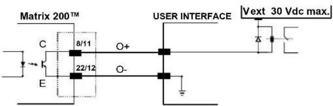
Figure 83 - Open Collector Output Connection
5.8 USER INTERFACE
The following table contains the pinout for standard RS232 PC Host interface. For other user interface types please refer to their own manual.
| RS232 PC-side connections | |||
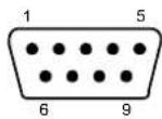 9-pin male connector 9-pin male connector | 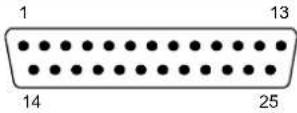 25-pin male connector 25-pin male connector | ||
| Pin | Name | Pin | Name |
| 2 | RX | 3 | |
| 3 | TX | 2 | |
| 5 | GND | 7 | |
| 7 | RTS | 4 | |
| 8 | CTS | 5 | |
How To Build A Simple Interface Test Cable:
The following wiring diagram shows a simple test cable including power, external (push-button) trigger and PC RS232 COM port connections.
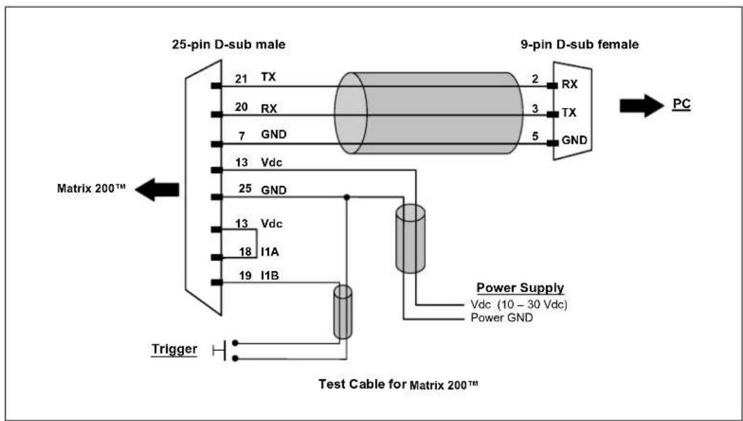
flowchart
graph TD
    A["25-pin D-sub male"] -->|TX| B["9-pin D-sub female"]
    A -->|RX| B
    A -->|GND| B
    C["Matrix 200™"] -->|Vdc| B
    D["13 Vdc"] --> B
    E["18 I1A"] --> B
    F["19 I1B"] --> B
    G["Trigger"] --> H["Test Cable for Matrix 200™"]
    B --> I["PC"]
    J["Power Supply: Vdc (10 - 30 Vdc), Power GND"] --> B
    style A fill:#f9f,stroke:#333
    style C fill:#f9f,stroke:#333
    style D fill:#f9f,stroke:#333
    style E fill:#f9f,stroke:#333
    style F fill:#f9f,stroke:#333
    style G fill:#f9f,stroke:#333
    style H fill:#f9f,stroke:#333
Figure 84- Test Cable for Matrix 200^TM
6 TYPICAL LAYOUTS
The following typical layouts refer to system hardware configurations. However, they also require the correct setup of the software configuration parameters. Dotted lines in the figures refer to optional hardware configurations within the particular layout.
6.1 POINT-TO-POINT
In this layout the data is transmitted to the Host on the main serial interface. The RS232 auxiliary interface can be used for reader configuration by connecting a laptop computer running VisiSet ^™ . Host Mode programming can be accomplished either through the main interface or the Auxiliary interface.
In Local Echo communication mode, data is transmitted on the RS232 auxiliary interface independently from the main interface selection.
When One Shot or Phase Mode operating mode is used, the reader can be activated by an External Trigger (for example a pulse from a photoelectric sensor) when the object enters its reading zone.
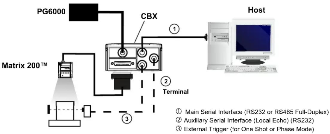
flowchart
graph TD
    A["PG6000"] --> B["Matrix 200™"]
    B --> C["CBX"]
    C --> D["Terminal"]
    D --> E["Host"]
    style A fill:#f9f,stroke:#333
    style B fill:#ccf,stroke:#333
    style C fill:#cfc,stroke:#333
    style D fill:#fcc,stroke:#333
    style E fill:#ffc,stroke:#333
    note1["① Main Serial Interface (RS232 or RS485 Full-Duplex)"]
    note2["② Auxiliary Serial Interface (Local Echo) (RS232)"]
    note3["③ External Trigger (for One Shot or Phase Mode)"]
Figure 85 – Serial Interface Point-to-Point Layout
In this layout a single scanner functions as a Slave node on a Fieldbus network. The data is transmitted to the Host through an accessory Fieldbus interface board installed inside the CBX500 connection box.
Reader configuration can be accomplished through the Auxiliary interface using the VisiSet ^™ configuration program or Host Mode programming.
In Local Echo communication mode, data is transmitted on the RS232 auxiliary interface independently from the Fieldbus interface selection.
When One Shot or Phase Mode operating mode is used, the reader can be activated by an External Trigger (photoelectric sensor) when the object enters its reading zone.
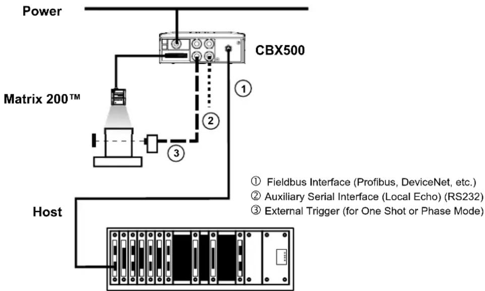
flowchart
graph TD
    A["Power"] --> B["Matrix 200™"]
    B --> C["Host"]
    C --> D["CBX500"]
    D --> E["Fieldbus Interface (Profibus, DeviceNet, etc.)"]
    D --> F["Auxiliary Serial Interface (Local Echo) (RS232)"]
    D --> G["External Trigger (for One Shot or Phase Mode)"]
Figure 86 – Fieldbus Interface Point-to-Point Layout
6.2 PASS-THROUGH
Pass-through mode allows two or more devices to be connected to a single external serial interface.
Each reader transmits the messages received by the Auxiliary interface onto the Main interface. All messages will be passed through this chain to the host.
When One Shot or Phase Mode operating mode is used, the reader can be activated by an External Trigger (for example a pulse from a photoelectric sensor) when the object enters its reading zone.
Applications can be implemented to connect a device such as a hand-held reader to the Auxiliary port of the last reader in the chain for manual code reading capability.
The Main and Auxiliary ports are connected as shown in the figure below:
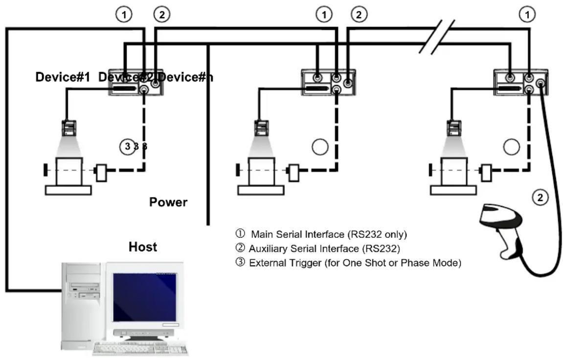
flowchart
graph TD
    A["Device#1"] --> B["Device#2"]
    B --> C["Device#3"]
    C --> D["Device#4"]
    D --> E["Device#5"]
    E --> F["Device#6"]
    F --> G["Device#7"]
    G --> H["Device#8"]
    H --> I["Device#9"]
    I --> J["Device#10"]
    style A fill:#f9f,stroke:#333
    style B fill:#f9f,stroke:#333
    style C fill:#f9f,stroke:#333
    style D fill:#f9f,stroke:#333
    style E fill:#f9f,stroke:#333
    style F fill:#f9f,stroke:#333
    style G fill:#f9f,stroke:#333
    style H fill:#f9f,stroke:#333
    style I fill:#f9f,stroke:#333
    style J fill:#f9f,stroke:#333
    note right of A: Power
    note left of H: Host
    note right of G: External Trigger (for One Shot or Phase Mode)
    note bottom of H: Main Serial Interface (RS232 only)
    note top of H: Auxiliary Serial Interface (RS232)
    note bottom of H: External Trigger (for One Shot or Phase Mode)
Figure 87 – Pass-Through Layout
6.3 ID-NET™
The ID-NET ^™ connection is used to collect data from several readers to build a multi-point or a multi-sided reading system; there can be one master and up to 31 slaves connected together.
The slave readers are connected together using the ID-NET ^™ interface. Every slave reader must have an ID-NET ^™ address in the range 1-31.
The master reader is also connected to the Host on the RS232/RS485 main serial interface.
For a Master/Slave Synchronized layout the External Trigger signal is unique to the system; there is a single reading phase and a single message from the master reader to the Host computer. It is not necessary to bring the External Trigger signal to all the readers.
In the Master/Slave Synchronized layout the Master operating mode can only be set to Phase Mode.
The main, auxiliary, and ID-NET ^™ interfaces are connected as shown in the figure below.
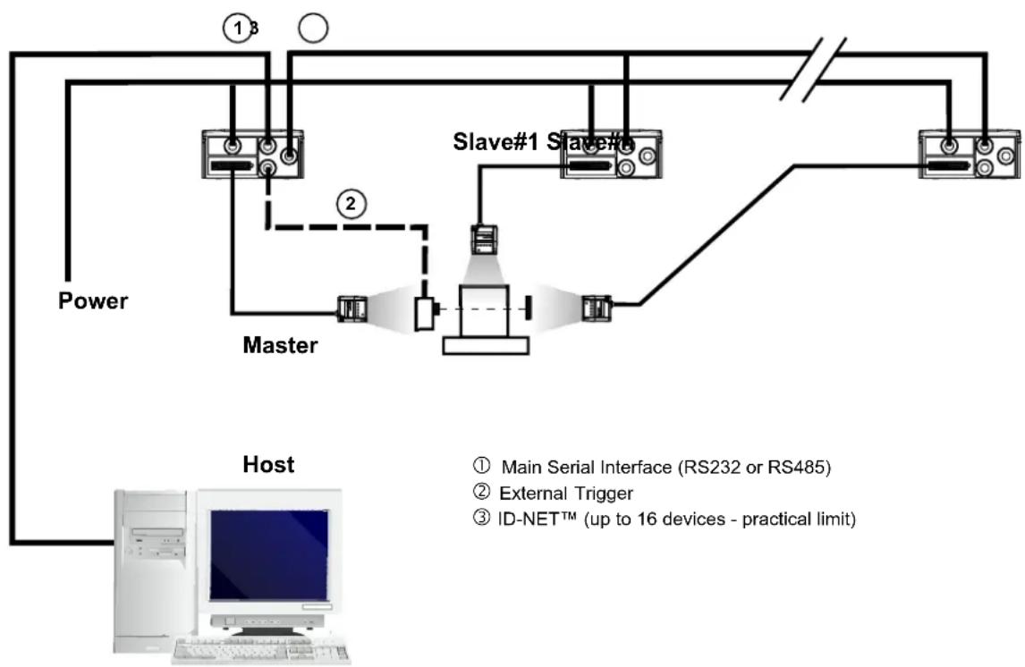
flowchart
graph TD
    A["Power"] --> B["Master"]
    B --> C["Slave#1 Slave#"]
    C --> D["Host"]
    D --> E["Computer"]
    style A fill:#f9f,stroke:#333
    style B fill:#ccf,stroke:#333
    style C fill:#cfc,stroke:#333
    style D fill:#fcc,stroke:#333
    note right of B: Master
    note left of D: Host
    note right of D: Main Serial Interface (RS232 or RS485)
    note right of D: External Trigger
    note right of D: ID-NET™ (up to 16 devices - practical limit)
For a Master/Slave Multidata layout each reader has its own reading phase independent from the others; each single message is sent from the master reader to the Host computer.
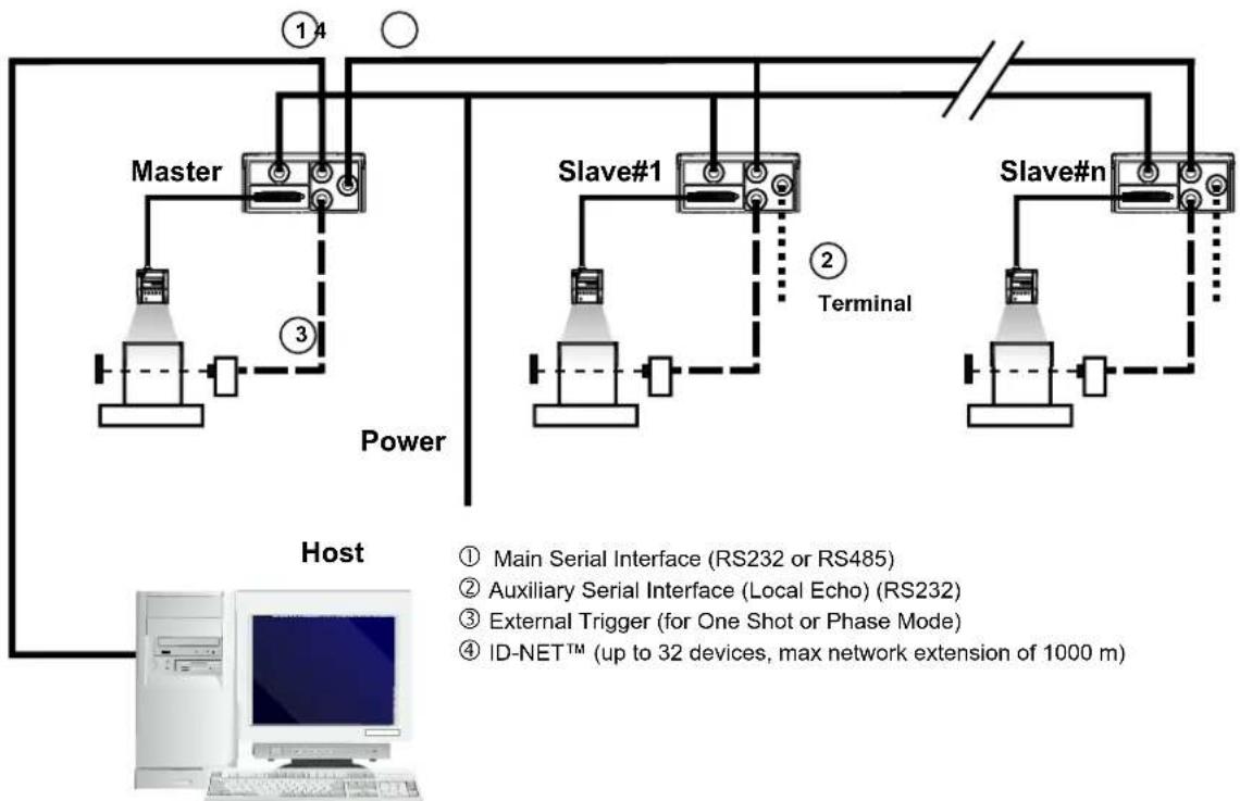
flowchart
graph TD
    A["Master"] --> B["Slave#1"]
    B --> C["Slave#n"]
    D["Host"] --> E["Master"]
    F["Terminal"] --> G["Slave#1"]
    H["Power"] --> I["Master"]
    J["ID-NET™ (up to 32 devices, max network extension of 1000 m)"] --> K["Computer"]
The auxiliary serial interface of the slave readers can be used in Local Echo communication mode to control any single reader (visualize collected data) or to configure it using the VisiSet™ utility.
The ID-NET ^™ termination resistor switches must be set to ON only in the first and last CBX connection box.
Alternatively, the Master scanner can communicate to the Host as a Slave node on a Fieldbus network. This requires using an accessory Fieldbus interface board installed inside the CBX500 connection box.
System configuration can be accomplished through the Auxiliary interface of the Master reader (internal CBX500 9-pin connector) using the VisiSet™ configuration program or Host Mode programming.
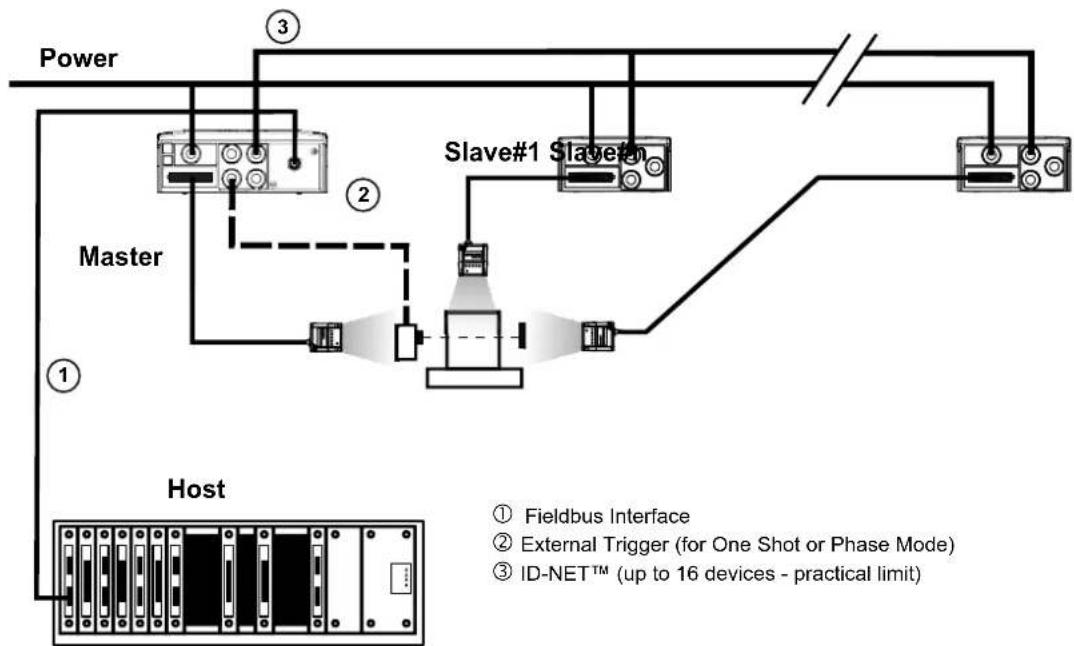
flowchart
graph TD
    A["Power"] --> B["Master"]
    B --> C["Slave#1"]
    C --> D["Slave#2"]
    D --> E["Host"]
    E --> F["Fieldbus Interface"]
    E --> G["External Trigger (for One Shot or Phase Mode)"]
    E --> H["ID-NET™ (up to 16 devices - practical limit)"]
This interface is provided for backward compatibility. We recommend using the more efficient ID-NET ^™ network for Master/Slave or Multiplexer layouts.
The RS232 master/slave connection is used to collect data from several readers to build either a multi-point or a multi-sided reading system; there can be one master and up to 9 slaves connected together.
The Slave readers use RS232 only on the main and auxiliary serial interfaces. Each slave reader transmits the messages received by the auxiliary interface onto the main interface. All messages will be passed through this chain to the Master.
The Master reader is connected to the Host on the RS232/RS485 main serial interface.
There is a single reading phase and a single message from the master reader to the Host computer.
In this layout the Master operating mode can be set only to Phase Mode.
The Phase ON/OFF signals must be brought only to the Master. It is not necessary to bring them to the Slave readers.
The main and auxiliary ports are connected as shown in the figure below.
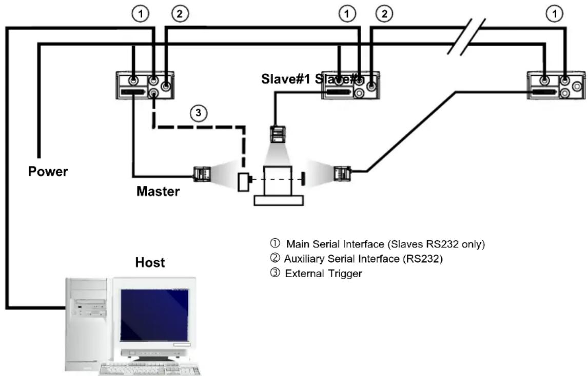
flowchart
graph TD
    A["Power"] --> B["Master"]
    B --> C["Slave#1 Slave#1"]
    C --> D["Host"]
    D --> E["Computer"]
    style A fill:#f9f,stroke:#333
    style B fill:#ccf,stroke:#333
    style C fill:#cfc,stroke:#333
    style D fill:#fcc,stroke:#333
    style E fill:#ffc,stroke:#333
    note right of B: Master & Slave#1 Slave#1
    note left of C: Main Serial Interface (Slaves RS232 only)
    note right of D: Auxiliary Serial Interface (RS232)
    note right of E: External Trigger
Figure 92 – RS232 Master/Slave Layout
6.5 MULTIPLEXER

NOTE
This interface is provided for backward compatibility. We recommend using the more efficient ID-NET ^™ network for Master/Slave or Multiplexer layouts.
Each reader is connected to a Multiplexer (for example MX4000) with the RS485 half-duplex main interface through a CBX connection box.
Before proceeding with the connection it is necessary to select the MUX32 communication protocol and the multidrop address for each reader.
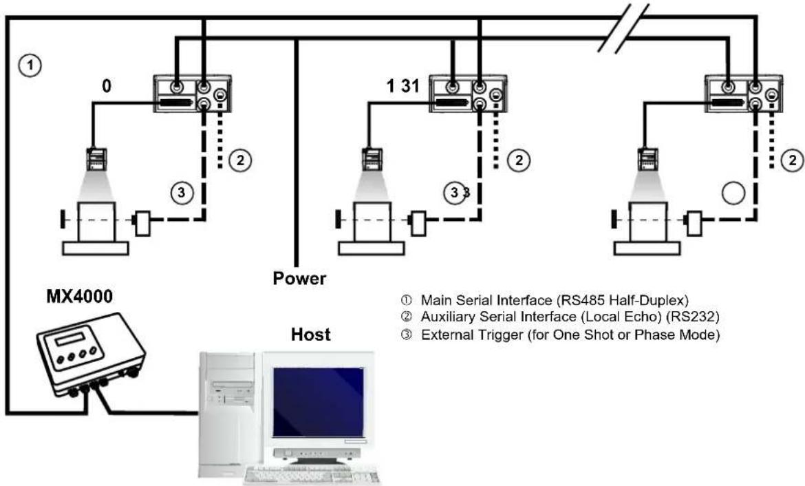
flowchart
graph TD
    A["Power"] --> B["Main Serial Interface (RS485 Half-Duplex)"]
    A --> C["Auxiliary Serial Interface (Local Echo) (RS232)"]
    A --> D["External Trigger (for One Shot or Phase Mode)"]
    E["MX4000"] --> F["Host"]
    F --> G["Computer"]
    style A fill:#f9f,stroke:#333
    style B fill:#ccf,stroke:#333
    style C fill:#ccf,stroke:#333
    style D fill:#ccf,stroke:#333
    style E fill:#dfd,stroke:#333
Figure 93 - Multiplexer Layout
The auxiliary serial interface of the slave readers can be used in Local Echo communication mode to control any single reader (visualize collected data) or to configure it using the VisiSet™ utility.
Each reader has its own reading phase independent from the others. When One Shot or Phase Mode operating mode is used, the reader can be activated by an External Trigger (for example a pulse from a photoelectric sensor) when the object enters its reading zone.
6.6 USB CONNECTION (MATRIX 200 XXX-X2X MODELS ONLY)
For Matrix 200 XXX-020 models, the USB connection is possible in two different layouts. The default baud rate is 115200. To maximize data transfer you can set it up to 921600 by configuring the reader though the Communication parameters via VisiSet™. For further details, see the Communication Folder in the VisiSet™ Help On Line.
In a Point-to-Point layout the reader is connected to a local host through its USB cable. No external power supply is necessary.
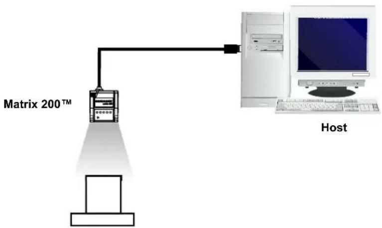
flowchart
graph TD
    A["Master 200™"] -->|Ethernet| B["Host"]
    B --> C["Computer"]
Figure 94 - USB Point-to-Point Layout
One or more Matrix 200 ^™ USB models can be connected to USB Hub. The HUB must be able to supply 500 mA to each port.
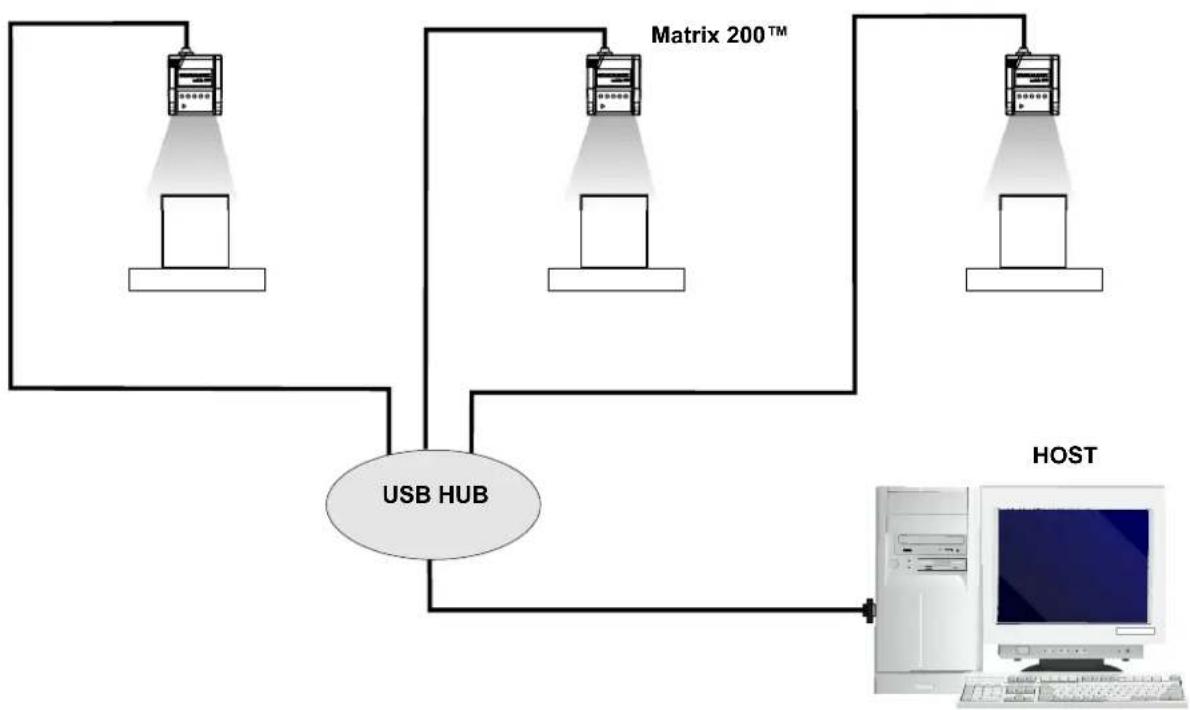
flowchart
graph TD
    A["Server 1"] --> B["USB HUB"]
    C["Server 2"] --> B
    D["Server 3"] --> B
    B --> E["Host"]
    style B fill:#f9f,stroke:#333
    style E fill:#ccf,stroke:#333
Figure 95 – Multi USB Hub Layout
7 READING FEATURES
| MODELS | Focus Distance mm (in) | Field of View ^(1) mm (in) | PPI ^(2) | Typ.Linear and Stacked Code Resolution mm (mils) | 2D Code Resolution mm (mils) | Reading Distance ^(3) mm (in) | ||
| min. | max. | |||||||
| Matrix 200 211-xxx | 45(1.77) | 35 × 22(1.38 × 0.87) | 546 | 0.10 (4) | Max. | 0.13 (5) 41 (1.61) 54 (2.13) | ||
| Typ. | 0.19 (7.5) 36 (1.42) 61 (2.40) | |||||||
| Matrix 200 212-xxx | 65(2.56) | 50 × 32(1.97 × 1.26) | 380 | 0.15 (6) | Max. | 0.19 (7.5) 54 (2.13) 91 (3.58) | ||
| Typ. | 0.25 (10) 47 (1.85) 103 (4.06) | |||||||
| Matrix 200 213-xxx | 105(4.13) | 80 × 50(3.15 × 1.97) | 240 | 0.20 (8) | Max. | 0.25 (10) 77 (3.03) 146 (5.75) | ||
| Typ. | 0.38 (15) 65 (2.56) 193 (7.60) | |||||||
(1) @ Focus Distance
(2) Pixels per inch @ Focus Distance
(3) Measurement Conditions:
• Test Chart: provided with the reader
• Still code at the center of the FOV
• Code Symbology: Data Matrix ECC 200
- Tilt Angle: 45^
- Skew Angle: 15^
• Image Processing Mode: Advanced Code Setting
- Module Size (mils) equal to the resolution of the code to read
• Image Processing Self Tuning enabled
• Image Processing Self Tuning Mode = Code Contrast Levels Only *
* This parameter setting increases the image processing time.
All distances indicated from the reading window to the code surface are the same for 90^ models.
Depending on the code resolution, symbology and number of characters in the code, the Reading Area can be different from the FOV.
7.1 MAXIMUM LINE SPEED CALCULATION
The Exposure Time (or Shutter) parameter defines the time during which the image will be exposed to the reader sensor to be acquired. This parameter depends heavily on the environmental conditions (external lighting, image contrast etc.).
In general, a longer time corresponds to a lighter image but is susceptible to blurring due to the code movement; a shorter exposure time corresponds to a darker image.

NOTE
The following considerations must be applied only when the internal lighting system and 2D codes are used. The Maximum line speed allowed for linear codes or postal code reading applications heavily depends on the direction of symbol movement. When the direction of movement is parallel to the elements of the code, the maximum speed is greater.
Assuming:
• X: Code Resolution (mm)
• Texp: Exposure Time (s)
• LS: Line Speed (mm/s)
The essential condition to avoid blurring effects between two adjacent elements in a dynamic reading application is:
$$ \mathrm{LS} \times \text { Texp } \leq X $$
The maximum (theoretical) line speed (LS) can be calculated as follows:
$$ X / \text { Texp (min) } = L S (\max) $$
Texp (min) is the minimum Exposure Time value obtainable for the specific application. It can be evaluated in static reading conditions and may depend on code printing quality, reader position, etc.
Using the formulas previously explained it is possible to calculate the theoretical maximum line (target) speed expected for the application, based on the maximum code resolution and the minimum suitable Exposure Time value.
The minimum Exposure Time value depends on the Matrix reader model selected for the application (reading distance) and on external lighting.
The Internal Lighting Mode parameter allows to set the operating mode of the internal lighting system. The possible values are:
- Disabled: the built-in lighting system is turned off all the time. This option can be useful only if external lighting is sufficient;
- Always ON: the built-in lighting system is turned on all the time at the lowest power level. This option is useful if the lighting system blinking (Strobed operating mode) disturbs the operator.
- Very High/High/Medium/Low-Power Strobed: the built-in lighting system is on only during the image exposure time. Four different lighting levels can be set.

To avoid LED array overheating, for Power Strobed settings, the program automatically limits the range of allowed values for the Exposure Time parameter. Therefore, after changes to Internal Lighting Mode, recheck Exposure Time.
CAUTION:
The maximum target speed in the application is affected by these conditions:
- Code/Background Contrast: maximum speed decreases when decreasing image contrast (poor quality codes, reflective transparent coverings, different supports and printing techniques).
- Code Resolution: maximum speed increases when decreasing code resolution (there is a decrement of overlapping effects between two adjacent elements).
- Tilt Angle: maximum speed decreases when increasing Tilt angle (from 0 to 45 degrees).
8 SOFTWARE CONFIGURATION
Software configuration of your Matrix 200 ^™ for static reading or simple code reading applications can be accomplished by the Rapid Configuration procedure using the X-PRESS ^™ HMI (which requires no external configuration program) or by using the VisiSet ^™ Autolearning Wizard for easy setup. These procedures are described in chapter 1.
For all other applications use VisiSet ^™ through the reader serial ports.
8.1 VISISET™ SYSTEM REQUIREMENTS
To install and run VisiSet ^™ you should have a Laptop or PC that meets or exceeds the following:
- Pentium processor
• Win 98/2000, NT 4.0, XP or Vista - 32 MB Ram
- 5 MB free HD space
• one free RS232 serial port with 115 Kbaud - SVGA board (800x600) or better using more than 256 colors
8.2 INSTALLING VISISET™
To install VisiSet ^TM , proceed as follows:
- Turn on the Laptop or PC that will be used for configuration (connected to the Matrix 200 ^TM communication ports).
- After Windows finishes booting, insert the CD-ROM provided.
- Launch VisiSet™ installation by clicking Install.
- Follow the instructions in the installation procedure.
8.3 STARTUP
After completing the mechanical and electrical connections to Matrix 200 ^™ , you can begin software configuration as follows:
- Power on the Matrix 200 ^™ reader. Wait for the reader startup. The system bootstrap requires a few seconds to be completed. The reader automatically enters Run Mode.
- Run the VisiSet ^TM program.
- Press Connect on the VisiSet™ menu bar. The PC will automatically connect to the Matrix 200™ reader.
Upon connection, Matrix 200 ^™ exits Run Mode and displays the Main Menu on VisiSet ^™ with all the commands necessary to monitor your reader's performance. You can select these commands using the mouse or by pressing the key corresponding to the letter shown on the button. See Figure 96.
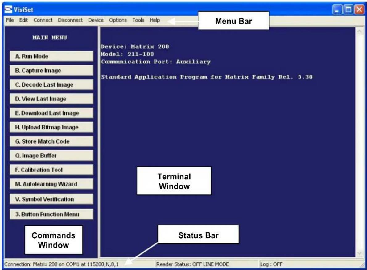
Figure 96 - Main Window
8.3.1 VisiSet™ Options
The Options item from the VisiSet™ menu (see Figure 96) presents a window allowing you to configure:
- the logging function (Log)
- VisiSet™ window properties (Environment)
- VisiSet™ communication channel (Communication)
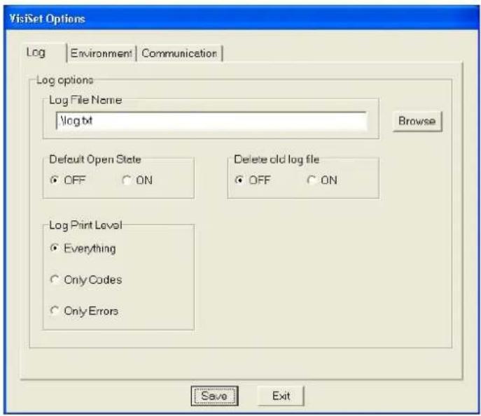
Figure 97 - Options - Log
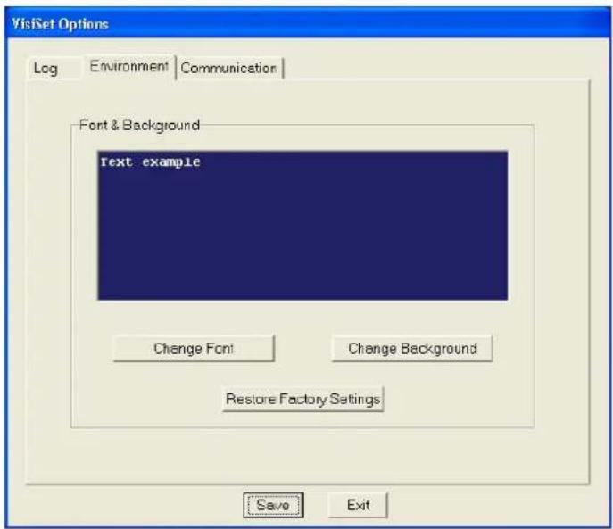
Figure 98 - Options - Environment
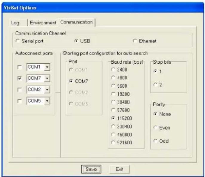
Figure 99 - Options – Communication
8.4 CONFIGURATION
Once connected to Matrix 200 ^™ as described in par. 8.3, you can modify the configuration parameters as follows:
- Press the Calibration Tool button from the Main Menu. Matrix 200 ^™ will download its permanent memory configuration parameters with the default values (if it is the first time) to VisiSet ^™ . The Calibration Tool window will be displayed together with the Parameter Setup window working in Interactive Mode (see par. 8.4.1 and par. 8.4.3).
- Edit the Matrix 200 ^™ configuration parameters according to your application requirements.
- Use the Calibration Tool to fine tune the reading performance. See par. 8.4.3.
- Close the Calibration Tool window and disable the Interactive Mode by pressing the interactive button.
- Save the new configuration to the reader permanent memory by pressing the Send button.
- Close the Parameter Setup window and press Disconnect on the VisiSet™ menu bar (see Figure 96) or launch Run Mode from the VisiSet™ Main menu.
Disconnect exits closing communication between Matrix 200 ^TM and VisiSet ^TM , and causes Matrix 200 ^TM to enter Run Mode. The disconnected reader serial port is now available.
Run command does not close communication between Matrix 200 ^TM and VisiSet ^TM , and causes Matrix 200 ^TM to enter Run Mode. In this case the reader output messages are displayed on the VisiSet ^TM terminal and the statistics are displayed in the Statistics window (Statistics enabled).
8.4.1 Edit Reader Parameters
The Parameter Setup window displays the configuration parameters grouped in a series of folders. Each parameter can be modified by selecting a different item from the prescribed list in the box, or by typing new values directly into the parameter box.
By right clicking the mouse when positioned over the name of a specific Parameter or Group, a pop-up menu appears allowing you to directly manage that particular parameter or group.
You can View the Selected Value for each parameter.
You can Restore the Default Value of each parameter or of all the parameters of a group.
Get Properties gives information about the parameter in the form of a pop-up hint that describes the default value and the range/list of valid values.
The Short Help gives information about the parameter in the form of a pop-up hint.
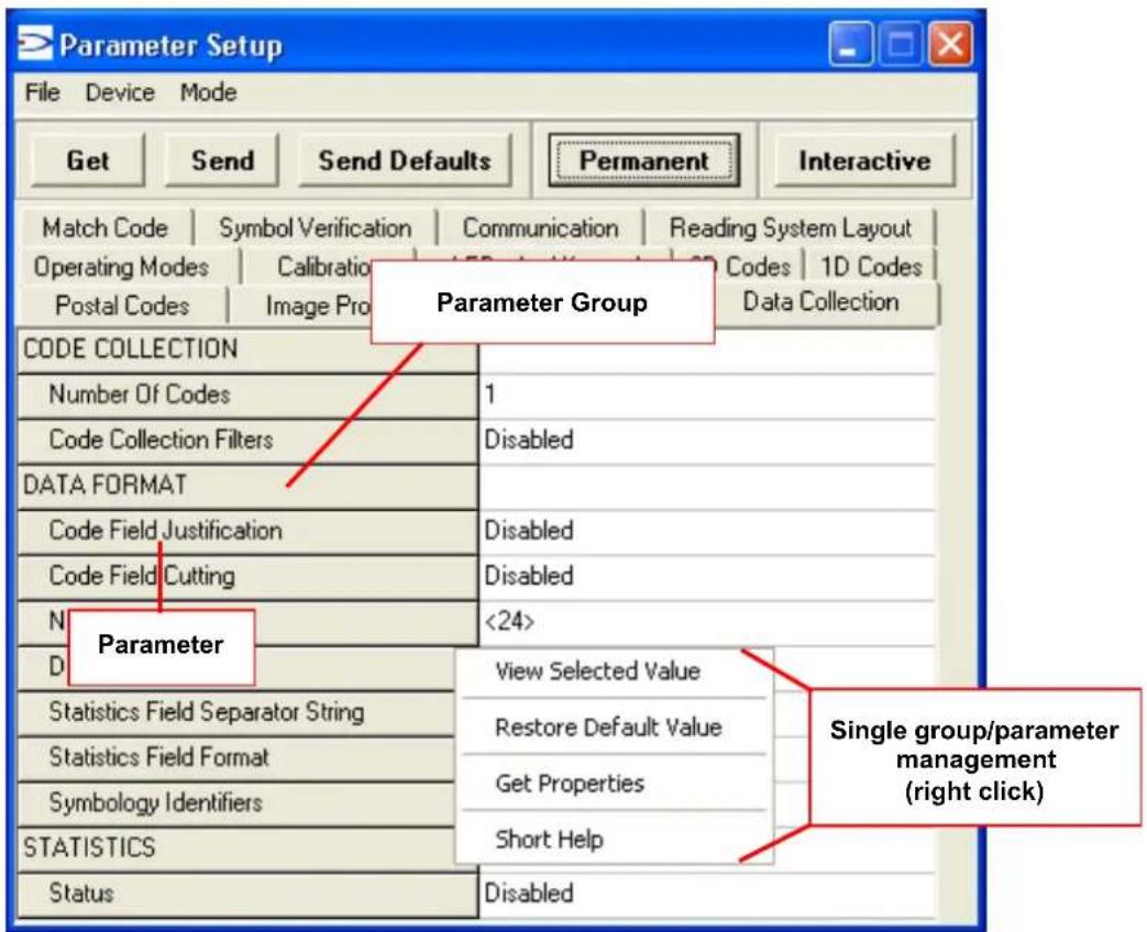
Figure 100 - Editing Parameters
Parameters to verify/modify:
| ☐ Operating Mode Sets the | parameters which customize the reader operating mode starting from three main modes:One Shot: acquires a single image based on the selected value for the Acquisition Trigger and Acquisition Trigger Delay.Continuous: continuously acquires images with a rate up to the maximum allowable frame rate per second for the given sensor depending on the decoding time and the Region of Interest settings.Phase Mode: acquires images during the reading phase depending on the selected value for the Acquisition Trigger and Acquisition Trigger Delay. The Reading Phase-ON and Reading Phase-OFF events mark respectively the beginning and end of the reading phase. |
| ☐ Calibration Calibrates | the acquisition parameters to maximize the reading performance (see par. 8.4.3). |
| ☐ Communication Configures | res the parameters relative to each serial port regarding the transmission, message formatting and string receiving.Any change to the VisiSetTM communication port parameters (baud rate, data bits, etc.) is effective as soon as the reader is disconnected from VisiSetTM. |
| ☐ Fieldbus Sets the parameters related to the External Fieldbus interface through the CBX500 and to its communication channels. | |
| ☐ Reading System Layout | Allows configuring the device according to the desired layout: Standalone, ID-NETTM or Master/Slave RS232 |
| ☐ Image Processing Sets the image processing parameters shared by all available symbologies. | |
| ☐ 1D & 2D, Postal Codes | Sets the characteristics of the code symbologies to be read. |
| ☐ Data Collection Defines the code-collection parameters and the output message format. | |
| ☐ Digital I/O Configures the reader input/output parameters. | |
| ☐ Match Code Allows setting a user-defined code and relative parameters to which the read code will be compared (matched). | |
| ☐ Miscellaneous Sets the reader name and the saved image format. | |
| ☐ Symbol Verification Sets the parameters relative to the various specifications in the Standards which regulate code validation. | |
| ☐ LEDs And Keypad | Sets the X-PRESSTM LED and Keypad parameters related to their selected Functions: Beeper, Green Spot, Autolearning, Positioning, etc. |
When all the configuration parameters are set correctly, save them to the Matrix 200 ^™ reader by pressing the Send button. See Figure 100.
For successive configuration of other readers or for backup/archive copies, it is possible to save the configuration onto your PC by selecting the Save Configuration File option from the File menu.
From the File menu, you can also Save Configuration As Text File for a human readable version.
Load Configuration File (available in the File menu) allows you to configure a reader from a previously saved configuration file (.ini).
8.4.2 Send Configuration Options
The device parameters are divided into two main classes, Configuration and Environmental which are effected differently by the Send Configuration and Send Default Configuration commands.
Configuration Parameters regard parameters that are specific to the device. These parameters are influenced by the Send Configuration and Send Default Configuration commands, that is they are overwritten by these commands. The same parameters are modified by the following "Send Configuration with Options" and "Send Default Configuration with Options" dialogs from the Device Menu:
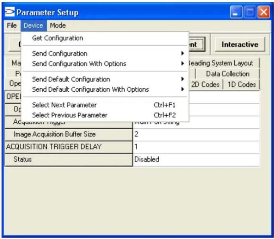
Environmental Parameters regard the device Identity and Position in a Network (ID-NET ^™ , Master/Slave RS232, MUX 32) and are not influenced by the "Send Default Configuration" and "Send Configuration" commands. This allows individual devices to be configured differently without affecting their recognized position in the network.
The following is a list of the Environmental Parameters:
READING SYSTEM LAYOUT
- Device Network Setting
- Number of Slaves
DEVICE NETWORK SETTINGS
- Topology Role
- ID-NET Slave Address
- Network Baud Rate
EXPECTED SLAVE DEVICES
- Status
- Device Description
- Device Network Name
MAIN PORT
- Communication Protocol
- Multidrop Address
MISCELLANEOUS
- Reader Name
- User Name
- Line Name
For device replacement it is necessary to send the previously saved configuration (both Configuration and Environmental parameters) to the new device. To do this select "Send Configuration with Options" from the Device Menu and check the Environmental Parameters checkbox:
In order to return a device to its absolute default parameters including Environmental parameters, the following Send Default Configuration with Options" dialog must be used:
8.4.3 Calibration
VisiSet™ provides a Calibration Tool to maximize the reading performance by tuning the acquisition parameters and the time of the delayed triggers.
By selecting the Calibration Tool from the VisiSet™ Main Menu (F), the following window appears together with the Parameter Setup window:
Figure 101 - Calibration OK
This tool provides a "real-time" image display while Matrix 200 ^TM is reading. It also gives immediate results on the performance of the installed Matrix 200 ^TM reader.
The Parameter Setup window works in Interactive Mode in order to cause each parameter setting to be immediately effective.

NOTE
If you want to save the temporary configuration to permanent memory, you must first close the Calibration Tool window. Then, you must disable the Interactive Mode and select the Permanent Memory option from the Send Configuration item in the Device menu.
The following examples show some of the typical conditions occurring during the installation:
Under-exposure:
To correct this result it is recommended to change the following parameters in their order of appearance:
- increase the Exposure Time
- increase theGain

NOTE
In general, a longer exposure time corresponds to a lighter image but is susceptible to blurring due to code movement. Exposure time is also limited by the Internal Lighting mode parameter. Longer exposure times can be set if the power strobe level is lowered.
High gain settings may produce a grainy image that may affect the decoding process.
![Calibration Tool Top,Left Stop Image Acquisition Disabled After Any Capture On No Decode On Decode Screen Mode Decoded Image Code Position Only Camera Mode Arm Trigger View Image Bottom Fight Download Image Parameter Setup File Device Mode Get Send Send Defaults Permanent Interactive 2D Codes 1D Codes Postal Codes Data Collection Digital I/O Match Code Miscellaneous Symbol Verification LEDs And Keypad Operating Modes Calibration Communication Ethernet Image Processing Image Acquisition Information Acquisition Setting 1 Self Tuning: Disabled Exposure Time (x10us): 20 Gain: 120 Decoding Results Symbology: Data Matrix ECC 200 Selected Code: 1 Code Data: Datalogic 2D Code Reader Code Center: (X , Y) = (307 , 213) Code Orientation: 170 Quality Index: 100% Image Lighting Quality Exposure Index : [ ] Lighting Index: 64% Underexposed OK Overexposed Statistical information on the last 10 samples Decode % 100% TX/RX Close IMAGE ACQUISITION SETTING 1 Status Enabled Self Tuning Disabled Internal Lighting Mode High-Power Strobed Exposure Time (x10us) 20 Gain 100 Gain Increasing x1 Image Polarity Inversion Disabled Region Of Interest: Top 7 Region Of Interest: Bottom 486 Region Of Interest: Left 10 Region Of Interest: Right 649 Image Filter Disabled](/content/2026/06/1280866/images/9a441646897738efb5fb050c36ce62fc6ff7d089fdbac3fd9522a0c7ee0ffbc8.jpg)
Figure 102 - Example Under Exposure: Too Dark
Over-exposure:
To correct this result it is recommended to change the following parameters in their order of appearance:
- decrease theGain
- decrease the Exposure Time
![Calibration Tool Top,Left Stop Image Acquisition Disabled After Any Capture On No Decode On Decode Screen Mode Decoded Image Code Position Only Camera Mode Arm Tigger View Image Bottom,Right Download Image Parameter Setup File Device Mode Get Send Send Defaults Permanent Interactive 2D Codes 1D Codes Postal Codes Data Collection Digital I/O Match Code Miscellaneous Symbol Verification LEDs And Keypad Operating Modes Calibration Communication Ethernet Image Processing Image Acquisition Information Acquisition Setting 1 Self Tuning: Disabled Exposure Time (x10us): 115 Gain: 280 Decoding Results Symbology: Data Matrix ECC 200 Selected Code: 1 Code Data: Datalogic 2D Code Reader Code Center: (X, Y) = [307,213] Code Orientation: 170 Quality Index: 56% Image Lighting Quality Exposure Index: Lighting Index: 83% Underexposed OK Overexposed Statistical information on the last 10 samples Decode % 100% TX/RX Close IMAGE ACQUISITION SETTING 1 Status Enabled Self Tuning Disabled Internal Lighting Mode High-Power Strobed Exposure Time (x10us) 50 Gain 280 Gain Increasing x1 Image Polarity Inversion Disabled Region Of Interest: Top 7 Region Of Interest: Bottom 486 Region Of Interest: Left 10 Region Of Interest: Right 649 Image Filter Disabled](/content/2026/06/1280866/images/a9a43544699ee8aae8c3b7102b377567c1df210b3c0ad47dcd2a01c9c8984e34.jpg)
Figure 103 - Example Over Exposure: Too Light
Moving code out of the Field of View:
To correct this result and have the code completely visible in F.O.V., it is possible to follow one or both the procedures listed below:
- reposition the reader
- use the Acquisition Trigger Delay by tuning the Delay Time (x100μs)
Figure 104 - Example out of FOV
8.4.4 Multi Image Acquisition Settings
When controlled variable conditions occur in the application, Multiple Image Acquisition Settings (up to 10), can be defined to create a database of parameter groups that handle each specific application condition. This database of pre-defined settings functions cyclically and therefore automatically improves system flexibility and readiness.
For example, an application may have two stable but different lighting conditions which require different lighting options. One Image Acquisition Setting could enable and use the internal illuminator and a second setting could disable Internal Lighting to use external lighting. These two groups will be used cyclically on each acquisition in order to automatically capture the correctly lighted image.
Image Acquisition Settings are found in the VisiSet™ Calibration parameter setup menu. By selecting a different number and enabling its Status you can define the parameters for a new group.
8.4.5 Run Time Self Tuning (RTST)
Run Time Self-Tuning (RTST) increases Matrix's flexibility in the presence of uncontrolled variable conditions (lighting, code contrast, etc.) by automatically adjusting its acquisition parameters.
Self Tuning Calibration
In the Calibration parameter setup menu, the Self Tuning parameters manage the Image Acquisition Setting parameters dynamically. Self Tuning provides automatic adjustment in run time of different acquisition parameters (Exposure Time and/or Gain) for each captured image based on calculations performed on previous acquisitions. These dynamic settings will be used instead of the static settings saved in memory.

For more details see the Matrix 200 ^™ Help On-Line.
Self Tuning Image Processing
In the Image Processing parameter setup menu, the Self Tuning parameters manage the Image Processing and Symbology related parameters. They perform different processing attempts on the same captured image according to the selected Self Tuning Mode parameter value: (Symbologies Only, Processing Modes Only, Decoding Methods Only, Code Contrast Levels Only, Image Mirroring Only, or General Purpose).
For more details see the Matrix 200 ^™ Help On-Line.
8.4.6 Region Of Interest Windowing
In order to satisfy very high throughput applications, higher frame rates can be achieved using the powerful Region Of Interest Windowing parameters in the Calibration parameter setup menu.
Region Of Interest Windowing allows defining a region or window within the reader FOV. The Top, Bottom, Left and Right parameters allow to precisely define the image window to be processed, visualized and saved.
In Matrix 200 ^™ the frame rate is dependent on the number of rows and columns in the defined window.
The smaller the window, the lower the frame period and consequently the higher the frame rate. In general the Image Processing time can be reduced by reducing the window dimensions.
![Calibration Tool Top,Left Stop Image Acquisition Disabled After Any Capture On No Decode On Decode Screen Mode Decoded Image Code Position Only Camera Mode Arm Trigger View Image Bottom,Right Download Image Parameter Setup File Device Mode Get Send Send Defaults Temporary Interactive Communication Reading System Layout Ethernet Data Collection Match Code Symbol Verification 2D Codes 1D Codes Postal Codes Image Processing Miscellaneous Operating Modes Calibration Digital I/O LEDs And Keypad IMAGE ACQUISITION SETTING 1 Status Enabled Self Tuning Disabled Internal Lighting Mode Disabled Exposure Time (x10us) 2000 Gain 550 Gain Increasing x1 Image Polarity Inversion Disabled Region Of Interest: Top 300 Region Of Interest: Bottom 900 Region Of Interest: Left 300 Region Of Interest: Right 1300 Image Filter Disabled Image Acquisition Information Acquisition Setting 1 Self Tuning Disabled Exposure Time (x10us) 2000 Gain 550 Decoding Results Symbolics: Code 128 Selected Code: 1 Code Date: 0.10 mm Code Center: (X,Y)= [837,606] Code Orientation 0 Image Lighting Quality Exposure Index: Undereexposed DC Overexposed Lighting Index 98% Statistical information on the last 10 samples: Decode % 100% TX/RX Close](/content/2026/06/1280866/images/22888abbfff875b9dd9b7f97bb94b3fd12596d55b4915c6b0cf81e24d2417392.jpg)
8.4.7 Direct Part Marking Applications
Decoding Method: Direct Marking
For DataMatrix and QR code the Decoding Method parameter selects the decoding algorithm according to the printing/marking technique used to create the symbol and on the overall printing/marking quality. The Direct Marking selection improves the decode rate for low quality Direct Part Mark codes and in general for Direct Part Mark codes with dot peening type module shapes.
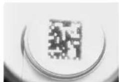
natural_image
Close-up of a pixelated square icon on a circular surface (no text or symbols)Washed out and Axial Distortion
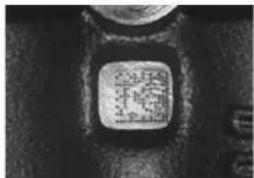
Dot Peening On Scratched Surface
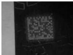
Low Contrast Problem
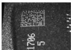
Background Problems
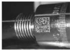
Marked On Curved Shiny Surface
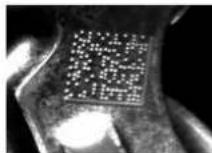
Axial distortion
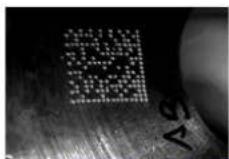
Half moon effects
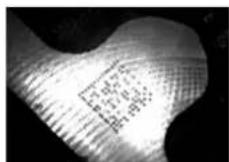
Shiny surface,
noisy background
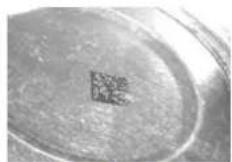
Low contrast,
noisy background
All the previous examples are successfully read selecting the Direct Marking Decoding Method.
Image Filter
Sets the filter to be applied to the image before being processed. This parameter can be used to successfully decode particular ink-spread printed codes (ex. direct part mark codes).
A different filter can be applied to each Image Acquisition Setting.
The Erode Filter enlarges the image dark zones to increase readability.
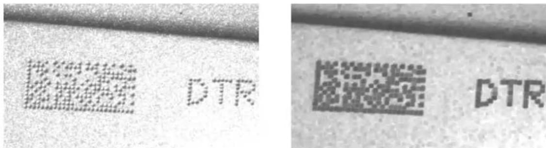
Before - No Read After - Readable
Erode
The Dilate Filter enlarges the image white zones to increase readability.
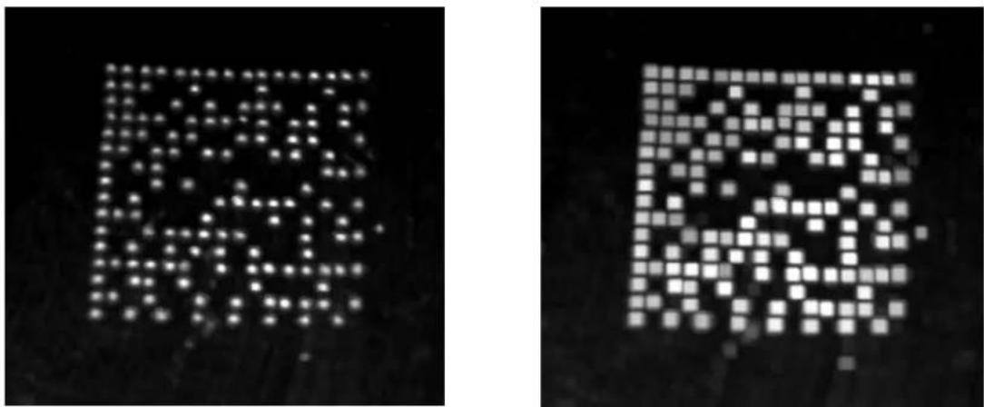
natural_image
Two pixelated square patterns on black background, no text or symbols presentBefore - No Read After - Readable
Dilate
The Close filter eliminates dark areas (defects) in the white zones of the image.
The Open filter eliminates white areas (defects) in the dark zones of the image.
8.5 IMAGE CAPTURE AND DECODING
By using the Capture Image and Decode Last Image functions from the VisiSet™ Main menu, you can get information about the image decodable codes in terms of Symbology, encoded Data, Position and Orientation, Decode Time and Code Quality Assessment Metrics.
![Main MENU A. Run Mode B. Capture Image C. Decode Last Image D. View Last Image E. Download Last Image H. Upload Bitmap Image Q. Image Buffer F. Calibration Tool M. Autolearning Wizard V. Symbol Verification 3. Button Function Menu Image captured (1280x1024) using Acquisition Setting #1 (Self Tuning disabled). ************************** Image Processing started (#8): New Code (#8.1): Symbolology: Data Matrix ECC 200 Number of Characters: 24 Code Center Position: (730,672) Pixel per Element: 12.1 Module Size: 24.0 mils @ Focus Distance Decoding Time (ms): 120 Code Orientation: 359° Code Bounds: TL[593,527] TR[867,535] DL[595,807] BR[867,810] Symbol Size: 20x20 Print Growth: 20% Code Quality Index: 100% ISO-IEC 15415 Quality Indicators: Overall Grade : A 4.0/20/660 (3) Decode : A Symbol Contrast : A (89%) Axial Non Uniformity : A (2%) Unused Error Correction: A (100%) Modulation : A Fixed Pattern Damage : A Grid Non Uniformity : A (25%) Data: Datalogic 2D Code Reader Image Exposure Quality: 100% Image Processing Time (ms): 122 ************************** Image Processing completed (#8).](/content/2026/06/1280866/images/42dd123ea884d43671348c4565db523d24d2cee80af1f5ea538dfe008891813f.jpg)
Figure 105 - Capture and Decoding Functions
8.6 STATISTICS
Statistics on the reading performance can be viewed by enabling the Statistics parameter and selecting the View Statistics item in the File menu. One of three different windows appears depending on the operating mode.
Refer to the VisiSet™ Help On Line for more details.
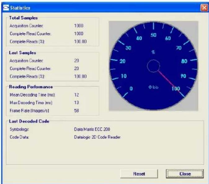
gauge
| Metric | Value | | --- | --- | | Total Samples | 1000 | | Acquired Counter | 1000 | | Complete Read Count | 100.00 | | Last Samples | 20 | | Acquired Counter | 20 | | Complete Read Count | 20 | | Complete Reads (%) | 100.00 | | Reading Performance | | | Mean Decoding Time (ms) | 12 | | Max Decoding Time (ms) | 13 | | Frame Rate (Images/s) | 58 | | Last Decoded Code | Data Matrix ECC 200 | | Symbolology: | Data Matrix ECC 200 | | Code Data: | Datalogic 2D Code Reader | Reset | CloseFigure 106 - Code Statistics
9 MAINTENANCE
9.1 CLEANING
Clean the reading window (see Figure A, 1) periodically for continued correct operation of the reader.
Dust, dirt, etc. on the window may alter the reading performance.
Repeat the operation frequently in particularly dirty environments.
Use soft material and alcohol to clean the window and avoid any abrasive substances.
10 TROUBLESHOOTING
10.1 GENERAL GUIDELINES
- When wiring the device, pay careful attention to the signal name (acronym) on the CBX100/500 spring clamp connectors (chp. 4). If you are connecting directly to the Matrix 200™ 25-pin male D-sub connector pay attention to the pin number of the signals (chp. 5).
- If you need information about a certain reader parameter you can refer to the VisiSet™ program help files. Either connect the device and select the parameter you're interested in by pressing the F1 key, or select Help>Parameters Help from the command menu.
- If you're unable to fix the problem and you're going to contact your local Datalogic office or Datalogic Partner or ARC, we suggest providing (if possible): Application Program version, Parameter Configuration file, Serial Number and Order Number of your reader. You can get this information while VisiSet™ is connected to the reader: the Application Program version is shown in the Terminal Window; the Parameter Configuration can be saved to an .ini file applying the File>Save Configuration File command in the Parameter Setup window; Serial Number and Order Number can be obtained by applying the respective command in the Tools menu.
| TROUBLESHOOTING GUIDE | |
| Problem | Suggestion |
| Power ON:the “POWER” LED is not lit. | Is power connected?If using a power adapter (like PG6000), is it connected to wall outlet?If using rail power, does rail have power?If using CBX, does it have power (check switch and LED)?Check if you are referring to the 25-pin connector or to the CBX spring clamp connectors.Measure Voltage either at pin 13 and pin 25 (for 25-pin connector) or at spring clamp Vdc and GND (for CBX). |
| One Shot or Phase Mode using the Input 1 (External Trigger) or Input 2:the "TRIGGER" LED is not blinking while the External Trigger is switching. | Check if you are referring to the 25-pin connector or to the CBX spring clamp connectors.Is the sensor connected to the Input 1 or Input 2?Is power supplied to the photo sensor?For NPN configuration, is power supplied to one of the two I1 or I2 signals (A or B)?For PNP configuration, is one of the two I1 or I2 signals grounded (A or B)?Are the photo sensor LEDs (if any) working correctly?Is the sensor/reflector system aligned (if present)?In the Digital I/O folder check the EXTERNAL TRIGGER or INPUT 2\Debounce Filter parameter setting.In the Operating Mode folder check the settings for Reading Phase-ON, Acquisition Trigger and Reading Phase-OFF parameters. |
| One Shot or Phase Mode using serial trigger source: the "TRIGGER" LED is not blinking. | In the Operating Mode folder check the settings for Reading Phase-ON, Acquisition Trigger and Reading Phase-OFF parameters.Are the COM port parameters (Baud Rate, Parity, Data Bits, Stop Bits, Handshake) correctly assigned?In the communication folder, check the settings of Reading Phase-ON String, Acquisition Trigger String and Reading Phase-OFF String parameters.Is the serial trigger source correctly connected? |
| Phase Mode: the "TRIGGER" LED is correctly blinking but no image is displayed in VisiSetTM Calibration Tool window. | Is the Phase frequency lower than the maximum frame rate? |
| Continuous Mode: the "TRIGGER" LED is not blinking. | Verify the correct software configuration settings. |
| Any Operating Mode: the "TRIGGER" LED is correctly blinking but no result is transmitted by the reader at the end of the reading phase collection. | In the Data Collection folder check the settings for the CODE COLLECTION, DATA FORMAT and STATISTICS parameter groups. |
| Image not clear: | Verify the Focus procedure |
| Image focused but not decoded: | Verify the Calibrate Image Density procedure. |
| Reading: the reader always transmits the No Read Message | Run the Rapid Configuration procedure in chapter 1.Position the reader as described in par. 3.3 and through the VisiSetTM Calibration Tool:- Tune the ACQUISITION TRIGGER DELAY, if the moving code is out of the reader field of view;- Set the Continuous Operating Mode if no external trigger source is available;- Tune the IMAGE ACQUISITION SETTING to improve the code image quality;- Check the parameter setting in Decoding, 2D Codes, 1D Codes, and Postal Codes folders;- View the full resolution code image to check the printing or marking quality. |
| Communication: reader is not transmitting anything to the host. | Is the serial cable wiring correct?If using CBX, be sure the RS485 termination switch is OFF.Are the host serial port settings the same as the reader serial port settings?In VisiSetTM Digital I/O folder, "COM" LED can be configured to indicate MAIN COM port TX or MAIN COM port RX. |
| Communication:data transferred to the host are incorrect, corrupted or incomplete. | Are the host serial port settings the same as the reader serial port settings?In VisiSetTM Communication folder check the settings of Header and Terminator String parameters.In VisiSetTM Data Collection folder, check the settings of DATA FORMAT parameter group. |
| How do I obtain my reader Serial Number? | The reader Serial Number consists of 9 characters: one letter, 2 numbers, another letter followed by 5 numbers.The reader Serial Number is printed on a label that is affixed on the bottom case near the reading window.The Serial Number can also be obtained by selecting Tools/Get Reader Serial Number from the command menu in VisiSetTM. A dedicated window will appear. |
| How do I obtain my reader Order Number? | The reader Order Number consists of 9 numbers.The reader Order Number can be obtained by selecting the Tools/Get Reader Order Number from the command menu in VisiSetTM. A dedicated window will appear. |
11 TECHNICAL FEATURES
| ELECTRICAL FEATURES | Matrix 200 21x-x0x models Matrix 200 21x-x2x models | |
| Power Supply Voltage 10 to 30 Vdc 5 Vdc Consumption 0.32 to 0.12 A, 3.6 W max. 0.5 A, 2.5 W max. 0.29 to 0.10 A, 3.0 W typ. 0.4 A, 2.0 W typ. | ||
| Communication Interfaces Main - RS232 - RS485 full-duplex - RS485 half-duplex Auxiliary - RS232 2400 to 115200 bit/s ID-NETTM Up to 1MBaud | 2400 to 115200 bit/s 2400 to 115200 bit/s 2400 to 115200 bit/s | USB 2.0 up to 921600 bit/s |
| Inputs Input 1 (External Trigger) and Input 2 | Opto-coupled and polarity insensitive | |
| Max. Voltage | 30 Vdc | |
| Max. Input Current | 10 mA | |
| Outputs Output 1 and Output 2 Opto-coupled | ||
| V_Out ( I_Load=0mA ) Max. | 30 Vdc | |
| V_Out ( I_Load=10mA ) Max. | 1.8 Vdc | |
| P_D=V_Out×I_LoadMax. | 170 mW | |
| OPTICAL FEATURES | ||
| Image Sensor | CMOS sensor with Global Shutter | |
| Image Format | WVGA (752x480) | |
| Frame Rate | up to 60 frames/sec. @ full window size | |
| Pitch | ±35° | |
| Tilt | 0°-360° | |
| Lighting System | Internal Illuminator | |
| LED Safety Class | Class 1 to EN60825-1 | |
| ENVIRONMENTAL FEATURES | ||
| Operating Temperature * | 0 to 50 °C (32 to 122 °F) | |
| Storage Temperature | -20 to 70 °C (-4 to 158 °F) | |
| Max. Humidity | 90% non condensing | |
| Vibration Resistance EN 60068-2-6 | 14 mm @ 2 to 10 Hz; 1.5 mm @ 13 to 55 Hz; 2 g @ 70 to 200 Hz; 2 hours on each axis | |
| Bump Resistance EN 60068-2-29 | 30g; 6 ms; 5000 shocks on each axis | |
| Shock Resistance EN 60068-2-27 | 30g; 11 ms; 3 shocks on each axis | |
| Protection Class EN 60529 | IP65 | |
| PHYSICAL FEATURES | Matrix 200 21x-1x0 models Matrix 200 21x-0x0 models | |
| Dimensions | 50 x 25 x 45 mm (1.97 x 0.98 x 1.77 in) | 50 x 32 x 45 mm (1.97 x 1.26 x 1.77 in) |
| Weight | 60 g. (2.1 oz.) without cable | |
| Material | Aluminium alloy | |
* high ambient temperature applications should use metal mounting bracket for heat dissipation
| SOFTWARE FEATURES | ||
| Readable Code Symbologies | ||
| 1-D and stacked | 2-D | POSTAL |
| PDF417 Standard and Micro PDF417Code 128 (EAN 128)Code 39 (Standard and Full ASCII)Interleaved 2 of 5CodabarCode 93PharmacodeEAN-8/13 - UPC-A/E(including Addon 2 and Addon 5)GS1 DataBar (RSS) FamilyComposite Symbologies | Data Matrix ECC 200(Standard and Direct Marking)QR Code(Standard and Direct Marking)MAXICODEAztec CodeMicroglyph(this symbology requires an activation procedure – contact your local Datalogic Automation distributor for details) | Australia PostRoyal Mail 4 State CustomerKix CodeJapan PostPLANETPOSTNETPOSTNET (+BB)Intelligent Mail |
| Operating Mode | ONE SHOT, CONTINUOUS, PHASE MODE | |
| Configuration Methods | X-PRESSTM Human Machine InterfaceWindows-based SW (VisiSetTM) via serial or USB linkSerial Host Mode Programming sequences | |
| Parameter Storage Permanent memory (Flash) | ||
| CODE QUALITY VERIFICATION | ||
| Standard | Supported | Symbologies |
| ISO/IEC 16022 Data Matrix ECC 200ISO/IEC 18004 QR CodeISO/IEC 15415 Data Matrix ECC 200, QRISO/IEC 15416 Code 128, Code 39, InterleAS9132A Data Matrix ECC 200AIM DPM Data Matrix ECC 200, QR Code | Codeaved 2 of 5, Codabar, Code 93, EAN-8/13, UPC-A/E | |
| USER INTERFACE | ||
| LED Indicators | Power, Ready, Good; Trigger; Com, Status; (Green Spot) | |
| Other | Keypad Button (configurable via VisiSetTM); Beeper | |
AIM
(Association for Automatic Identification and Mobility): AIM Global is the international trade association representing automatic identification and mobility technology solution providers.
AIM DPM Quality Guideline
Standard applicable to the symbol quality assessment of direct part marking (DPM) performed in using two-dimensional bar code symbols. It defines modifications to the measurement and grading of several symbol quality parameters.
AS9132
Standard defining uniform quality and technical requirements for direct part marking (DPM) using Data Matrix symbologies.
Barcodes (1D Codes)
A pattern of variable-width bars and spaces which represents numeric or alphanumeric data in machine-readable form. The general format of a barcode symbol consists of a leading margin, start character, data or message character, check character (if any), stop character, and trailing margin. Within this framework, each recognizable symbology uses its own unique format.
BIOS
Basic Input Output System. A collection of ROM-based code with a standard API used to interface with standard PC hardware.
Bit
Binary digit. One bit is the basic unit of binary information. Generally, eight consecutive bits compose one byte of data. The pattern of 0 and 1 values within the byte determines its meaning.
Bits per Second (bps)
Number of bits transmitted or received per second.
Byte
On an addressable boundary, eight adjacent binary digits (0 and 1) combined in a pattern to represent a specific character or numeric value. Bits are numbered from the right, 0 through 7, with bit 0 the low-order bit. One byte in memory can be used to store one ASCII character.
Composite Symbolologies
Consist of a linear component, which encodes the item's primary data, and an adjacent 2D composite component, which encodes supplementary data to the linear component.
Dark Field Illumination
Lighting of surfaces at low angles used to avoid direct reflection of the light in the reader's lens.
Decode
To recognize a barcode symbology (e.g., Codabar, Code 128, Code 3 of 9, UPC/EAN, etc.) and analyze the content of the barcode scanned.
Depth of Field
The difference between the minimum and the maximum distance of the object in the field of view that appears to be in focus.
Diffused Illumination
Distributed soft lighting from a wide variety of angles used to eliminate shadows and direct reflection effects from highly reflective surfaces.
Direct Part Mark (DPM)
A symbol marked on an object using specific techniques like dot peening, laser etching, chemical etching, etc.
EEPROM
Electrically Erasable Programmable Read-Only Memory. An on-board non-volatile memory chip.
Element
The basic unit of data encoding in a 1D or 2D symbol. A single bar, space, cell, dot.
Exposure Time
For digital cameras based on image sensors equipped with an electronic shutter, it defines the time during which the image will be exposed to the sensor to be acquired.
Flash
Non-volatile memory for storing application and configuration files.
Host
A computer that serves other terminals in a network, providing services such as network control, database access, special programs, supervisory programs, or programming languages.
Image Processing
Any form of information processing for which the input is an image and the output is for instance a set of features of the image.
Image Resolution
The number of rows and columns of pixels in an image. The total number of pixels of an image sensor.
Image Sensor
Device converting a visual image to an electric signal. It is usually an array of CCD (Charge Coupled Devices) or CMOS (Complementary Metal Oxide Semiconductor) pixel sensors.
IEC
(International Electrotechnical Commission): Global organization that publishes international standards for electrical, electronic, and other technologies.
IP Address
The terminal's network address. Networks use IP addresses to determine where to send data that is being transmitted over a network. An IP address is a 32-bit number referred to as a series of 8-bit numbers in decimal dot notation (e.g., 130.24.34.03). The highest 8-bit number you can use is 254.
ISO
(International Organization for Standardization): A network of the national standards institutes of several countries producing world-wide industrial and commercial standards.
LED (Light Emitting Diode)
A low power electronic light source commonly used as an indicator light. It uses less power than an incandescent light bulb but more than a Liquid Crystal Display (LCD).
LED Illuminator
LED technology used as an extended lighting source in which extra optics added to the chip allow it to emit a complex radiated light pattern.
Matrix Symbologies (2D Codes)
An arrangement of regular polygon shaped cells where the center-to-center distance of adjacent elements is uniform. Matrix symbols may include recognition patterns which do not follow the same rules as the other elements within the symbol.
Multidrop
A communication protocol for connecting two or more readers in a network with a concentrator (or controller) and characterized by the use of individual device addresses.
Multi-row (or Stacked) Symbologies
Symbologies where a long symbol is broken into sections and stacked one upon another similar to sentences in a paragraph.
RAM
Random Access Memory. Data in RAM can be accessed in random order, and quickly written and read.
Symbol Verification
The act of processing a code to determine whether or not it meets specific requirements.
Transmission Control Protocol/Internet Protocol (TCP/IP)
A suite of standard network protocols that were originally used in UNIX environments but are now used in many others. The TCP governs sequenced data; the IP governs packet forwarding. TCP/IP is the primary protocol that defines the Internet.
2
25-Pin Connector; 51
25-Pin Direct Connections; 51
A
Accessories; 25
Application Examples; 25
Auxiliary RS232 Interface; 44; 62
C
Calibration; 91
CBX Electrical Connections; 33
Compliance; vii
E
Edit Reader Parameters; 86
G
General View; x
Glossary; 106
H
Handling; viii
|
ID-NET™; 72
Image Capture and Decoding; 99
Inputs; 45; 63
Installing VisiSet™; 81
L
Layouts; 69
M
Main Serial Interface; 34; 52
Maintenance; 100
Mechanical Dimensions; 29
Model Description; 24
Mounting and Positioning Matrix 200™; 31
Multiplexer; 76
0
Outputs; 48; 66
P
Package Contents; 28
Pass-Through; 71
Patents; vi
Point-to-Point; 69
Power Supply; vii; 34; 52
R
Rapid Configuration; 1
Reader Configuration; 85
Reading Features; 78
References; vi
RS232 Interface; 35; 53
RS232 Master/Slave; 75
RS485 Full-Duplex; 36; 54
RS485 Half-Duplex; 37; 55
s
Service and Support; vi
Software Configuration; 81
Statistics; 99
T
Technical Features; 104
Troubleshooting; 101
U
USB Connection; 77
v
VisiSet™ Options; 83
Datalogic Automation S.r.l.
Via S. Vitalino 13
are in conformity with the requirements of the European Council Directives listed below:
89/336/EEC EMC Directive
e
and
On the approximation of the laws of Member States relating to electromagnetic compatibility and product safety.
This declaration is based upon compliance of the products to the following standards:
EN 55022 (Class A ITE), September 1998:
INFORMATION TECHNOLOGY EQUIPMENT
RADIO DISTURBANCE CHARACTERISTICS
LIMITS AND METHODS OF MEASUREMENTS
EN 61000-6-2, September 2005:
ELECTROMAGNETIC COMPATIBILITY (EMC)
PART 6-2: GENERIC STANDARDS - IMMUNITY FOR INDUSTRIAL
ENVIRONMENTS
Lippo di Calderara, July 11th, 2008 Lorenzo Girotti
Product & Process Quality Manager
Gren's Park