
KZ550 (1985) - Motorcycle KAWASAKI - Free user manual and instructions
Find the device manual for free KZ550 (1985) KAWASAKI in PDF.


| Product Type | Motorcycle User Manual |
| Brand | Kawasaki |
| Model | KZ550 (1985) |
| Engine Type | 4-stroke, air-cooled, inline 4-cylinder |
| Displacement | 553 cc |
| Max Power | 55 hp @ 9500 rpm (approx.) |
| Transmission | 6-speed manual |
| Front Brake | Dual disc |
| Rear Brake | Single disc |
| Suspension (Front) | Telescopic fork |
| Suspension (Rear) | Dual shocks, adjustable preload |
| Fuel System | 4 carburetors (Keihin CVK) |
| Fuel Capacity | 13 liters (approx.) |
| Oil Capacity (with filter) | 2.8 liters |
| Spark Plug | NGK B8ES or equivalent |
| Weight (wet) | 210 kg (approx.) |
| Seat Height | 785 mm (approx.) |
| Maintenance Interval | Every 3000 km or 6 months |
| Manual Pages | 341 |
| Manual Languages | English (original), translations available |
Frequently Asked Questions - KZ550 (1985) KAWASAKI
User questions about KZ550 (1985) KAWASAKI
0 question about this device. Answer the ones you know or ask your own.
Ask a new question about this device
Download the instructions for your Motorcycle in PDF format for free! Find your manual KZ550 (1985) - KAWASAKI and take your electronic device back in hand. On this page are published all the documents necessary for the use of your device. KZ550 (1985) by KAWASAKI.
USER MANUAL KZ550 (1985) KAWASAKI
KAWASAKI
KZ500/550 & ZX550 · 1979-1985
SERVICE·REPAIR ·MAINTENANCE
Chapter One
General Information
Chapter Two
Troubleshooting
Chapter Three
Periodic Maintenance, Lubrication and Tune-up
Chapter Four
Engine
Chapter Five
Clutch
Chapter Six
Transmission
Chapter Seven
Fuel and Exhaust
Chapter Eight
Electrical Systems
Chapter Nine
Wheels, Tires and Brakes
Chapter Ten
Chassis
Supplement
1982 and Later Service Information
Index
The image is too blurry to recognize any text content.

3

4

5

6

7

8

9

10
11

12

13
Wiring Diagrams

CONTENTS
QUICK REFERENCE DATA ...... XI
CHAPTER ONE
GENERAL INFORMATION .... 1
Manual organization
Service hints
Safety first
Expendable supplies
Shop tools
Emergency tool kits
Troubleshooting and tune-up
equipment
CHAPTER TWO
TROUBLESHOOTING 9
Starting difficulties
Poor performance
Clutch and transmission
Drive train
Chassis
Brakes
Electrical system
Charging system
Lighting
Fuses
Wiring
CHAPTER THREE
LUBRICATION, MAINTENANCE AND TUNE-UP 33
Battery
Engine oil and filter
General lubrication
Clutch adjustment
Drive chain
Swing arm
Steering
Front forks
Rear shock absorbers
Tires
Wheel bearing lubrication
Disc brake
Drum brake
Engine tune-up
Air filter
Nuts, bolts and fasteners
Fuel system
Spark plugs
Air suction valves (U.S. models)
Valve clearance
Contact breaker points
Ignition timing
(Contact point ignition)
Ignition timing
(Transistorized ignition)
Carburetor
Cylinder compression
Storage
CHAPTER FOUR
ENGINE 70
Tools
Engine design
Break-in
Servicing engine in frame
Cam chain and tensioner
Valve cover
Camshaft
Cylinder head
Valves and guides
Cylinder block
Pistons and rings
Oil cooler
Removal/installation
Oil filter bypass valve
Oil pump
Crankcase
Secondary shaft and starter clutch
Crankshaft and connecting rods
Cam chain inspection
Primary chain inspection
Crankcase assembly
CHAPTER FIVE
CLUTCH 124
Operation
Clutch release mechanism
Clutch
CHAPTER SIX
TRANSMISSION 133
Sprocket cover
Neutral switch
Engine sprocket
Shift linkage
Shift detent
Transmission
Shift drum and forks
Transmission gears
CHAPTER SEVEN
FUEL AND EXHAUST SYSTEMS 148
Carburetor operation
Carburetor troubleshooting
Rejetting
Carburetor tuning
Carburetor service
Fuel level inspection
Idle mixture adjustment
(Non-U.S. models)
Fast idle adjustment
Crankcase breather
Air suction system
(U.S. models)
Fuel tank
Fuel tap
Fuel level sending unit
Exhaust system
CHAPTER EIGHT
Contact breaker points and
condenser service
Spark plugs
Ignition advance mechanism
Ignition coil
Pickup coils
(Transistorized ignition)
Alternator stator
Alternator rotor
Starting system
Starter motor
Starter clutch
Starter solenoid
Lighting system
Turn signal cancelling system
Fuel level sensor
Fuel gauge
Hom
CHAPTER NINE
WHEELS, TIRES AND BRAKES 192
Wheels
Front wheel
Speedometer gear lubrication
Rear wheel
Wheel bearings and seals
Tubeless tires
Brakes
Hydraulic disc brakes
Brake system bleeding
Brake fluid change
Brake line replacement
Disc brake pad replacement
Disc brake calipers
Master cylinder rebuilding
Front master cylinder
Rear master cylinder
Brake discs
Drum brake
CHAPTER TEN
CHASSIS 228
Fairing
Front forks
Steering head
Rear shock
Swing arm
Drive chain
SUPPLEMENT
1982 AND LATER SERVICE INFORMATION 246
INDEX 307
WIRING DIAGRAMS ...... End Of Book
QUICK REFERENCE DATA
0.024-0.028 in. (0.6-0.7 mm)

SPARK PLUG GAP
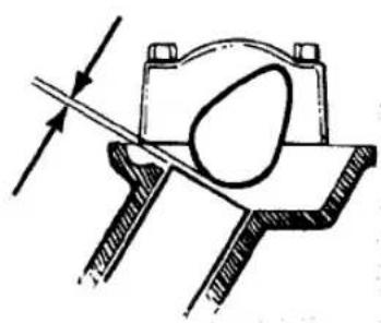
VALVE CLEARANCE
Intake-0.004-0.008 in. (0.10-0.20 mm)
Exhaust-0.006-0.010 in. (0.15-0.25 mm)
B. Timing for cylinders #1 and #4
C. Timing for cylinders #2 and #3

CYLINDER HEAD
TORQUE
SEQUENCE
TIRES AND TIRE PRESSURE
| Model/Tire size | Pressure @ load | |
| 0-215 lb. (0-97.5 kg) | Over 215 lb. (Over 97.5 kg) | |
| KZ500-B1, B2, KZ550-A1 (tube-type) | ||
| Front—3.25H-19 4PR | 28 psi (200 kPa) | 28 psi (200 kPa) |
| Rear—3.75-18 4PR | 36 psi (245 kPa) | 40 psi (280 kPa) |
| KZ500-B3, KZ550-A2,B2,D1 (tubeless) | ||
| Front—3.25H-19 4PR | 28 psi (200 kPa) | 28 psi (200 kPa) |
| Rear—3.75H-18 4PR | 32 psi (225 kPa) | 40 psi (280 kPa) |
| KZ550-C1, C2 (tubeless) | ||
| Front—3.25S-19 4PR | 25 psi (175 kPa) | 25 psi (175 kPa) |
| Rear—130/90-16 67H PR | 21 psi (150 kPa) | 28 psi (200 kPa) |
| KZ550-H1 (tubeless) | ||
| Front—3.25H-19 4PR | See tire data decal | |
| Rear—4.00-18 4PR | ||
| KZ550-F1, M1 (tubeless) | ||
| Front—100/90-19 57S | 25 psi (175 kpa) | 25 psi (175 kPa) |
| Rear—130/90-16 67S | 21 psi (147 kPa) | 28 psi (196 kPa) |
| ZX550-A1, A2 (tubeless) | ||
| Front—100/90-18 56H | 28 psi (196 kPa) | 28 psi (196 kPa) |
| Rear—120/80-18 62H | 32 psi (225 kPa) | 36 psi (245 kPa) |
TUNE-UP SPECIFICATIONS
| Spark plug gap | 0.024-0.028 in. (0.6-0.7 mm) |
| Spark plug type | |
| 1979-1981; 1982-on U.S. | NGK D8EA; ND X24ES-U |
| 1982-on non-U.S. | NGK D8ES; ND X24ESR-U |
| Valve clearance (cold) | |
| Intake | 0.004-0.008 in. (0.10-0.20 mm) |
| Exhaust | 0.006-0.010 in. (0.15-0.25 mm) |
| Idle speed | |
| ZX550-A1, A2 | 1,150-1,250 rpm |
| All other models | 1,000-1,100 rpm |
FASTENER TORQUES
| ft.-lb. | mkg | |
| Alternator rotor bolt | 50 | 7.0 |
| Camshaft cap bolts | 8.5 | 1.2 |
| Clutch hub nut | 100 | 13.5 |
| Connecting rod cap nuts | 17.5 | 2.4 |
| Crankcase bolts | ||
| Small | 90 in.-lb. | 1.0 |
| Large | 18 | 2.5 |
| Cylinder base nuts | 8.5 | 1.2 |
| Cylinder head | ||
| Bolts | 8.5 | 1.2 |
| Nuts | 17 | 2.3 |
| Engine mounting bolts | ||
| KZ550-H1, F1, M1 | 25 | 3.5 |
| All others | 29 | 4.0 |
| Engine mounting bracket bolts | 17.5 | 2.4 |
| Engine sprocket plate bolts | 90 in.-lb. | 1.0 |
| Oil drain plug | ||
| Except KZ550-F1, M1 | 27 | 3.8 |
| KZ550-F1, -M1 | 22 | 3.0 |
| Oil filter mounting bolt | 14.5 | 2.0 |
| Secondary shaft nut | 45 | 6.0 |
| Spark plugs | 10 | 1.4 |
| Chassis | ||
| Front axle nut | ||
| KZ550-F1, M1 | 47 | 6.5 |
| All others | 58 | 8.0 |
| Front axle pinch bolt | 14.5 | 2.0 |
| Front fork clamp bolts | ||
| KZ550-F1, M1 | ||
| Upper | 15 | 2.1 |
| Lower | 20 | 2.8 |
| All other models | 13 | 1.8 |
| Rear axle nut | ||
| KZ550-F1, M1 | 54 | 7.5 |
| ZX550-A1, A2 | 69 | 9.5 |
| All others | 60 | 8.0 |
| Steering stem head bolt | ||
| KZ550-H1, F1, M1 | 31 | 4.3 |
| All other models | 35 | 4.5 |
| Swing arm pivot shaft | ||
| KZ550-H1 | 58 | 8.0 |
| KZ550-F1, M1 | 9.5 | 1.3 |
| ZX550-A1, A2 | 65 | 90 |
LUBRICANTS AND FUEL
| Engine oil | SAE 10W-40, 10W-50, 20W-40, 20W-50, rated SE or higher |
| Front fork oil | SAE 5W20 |
| Fuel | 87 pump octane (RON ± MON)/291 research octane (RON) |
| Final drive gear oil | API GL-5 Hypoid gear oil; SAE 80 or SAE 90 |
FORK AIR PRESSURE*
| Model | Standard | Range |
| KZ550-C | 8.5 psi (60 kPa) | 7-10 psi (50-70 kPa) |
| KZ550 | ||
| F1, M1 | 7.5 psi (59 kPa) | 7-10 psi (49-69 kPa) |
| H1 | 10.0 psi (70 kPa) | 8.5-11 psi (60-80 kPa) |
| All others | 10 psi (70 kPa) | 8.5-11 psi (60-80 kPa) |
| * Never exceed 36 psi (245 k Pa) air pressure as it will damage the oil seals. | ||
REAR SHOCK AIR PRESSURE*
| Model | Standard | Range |
| KZ550F1 | 11 psi (78 kPa) | 11-10 psi (78-147 kPa) |
| * Never exceed 71 psi (490 kPa) air pressure as it will damage the oil seals. | ||
STANDARD FORK OIL* (1982-on)
| Model | Dry capacityU.S. fl. oz. (cc) | Wet capacityU.S. fl. oz. (cc) | Oil levelin. (mm) |
| KZ550-H1 | 7.9 ± 0.1(234 ± 2.5) | 7.2(215) | 19.8 ± 0.1(503 ± 2) |
| KZ550-F1, M1 | 11.05 ± 0.15(327 ± 4) | 9.4(280) | 16.3 ± 0.1(416 ± 2) |
| ZX550-A1, A2 | 7.7 ± 0.08(229 ± 2.5) | ** | 18.58 ± 0.1472 (± 2) |
| * Fork oil level is checked with forks fully extended and the fork spring removed. Use oil grade SAE 5W-20.** Not specified. | |||
INTRODUCTION
This detailed, comprehensive manual covers Kawasaki KZ500/550 and ZX550 models. The expert text gives complete information on maintenance, repair and overhaul. Hundreds of photos and drawings guide you through every step. The book includes all you need to know to keep your bike running right.
Chapters One through Ten contain general information on all models and specific information on 1979-1981 models. The Supplement at the end of the book contains information on 1982 and later models that differ from earlier years. Where repairs are practical for the owner/mechanic, complete procedures are given. Equally important, difficult jobs are pointed out. Such operations are usually more economically performed by a dealer or independent garage.
A shop manual is a reference. You want to be able to find information fast. As in all Clymer books, this one is designed with this in mind. All chapters are thumb tabbed. Important items are indexed at the end of the book. All the most frequently used specifications and capacities are summarized on the Quick Reference pages at the beginning of the book.
Keep the book handy. It will help you to better understand your Kawasaki, lower repair and maintenance costs and generally improve your satisfaction with your bike.
CHAPTER ONE
GENERAL INFORMATION
The troubleshooting, maintenance, tune-up, and step-by-step repair procedures in this book are written specifically for the owner and home mechanic. The text is accompanied by helpful photos and diagrams to make the job as clear and correct as possible.
Troubleshooting, maintenance, tune-up, and repair are not difficult if you know what to do and what tools and equipment to use. Anyone of average intelligence, with some mechanical ability, and not afraid to get their hands dirty can perform most of the procedures in this book.
In some cases, a repair job may require tools or skills not reasonably expected of the home mechanic. These procedures are noted in each chapter and it is recommended that you take the job to your dealer, a competent mechanic, or a machine shop.
MANUAL ORGANIZATION
This chapter provides general information, safety and service hints. Also included are lists of recommended shop and emergency tools as well as a brief description of troubleshooting and tune-up equipment.
Chapter Two provides methods and suggestions for quick and accurate diagnosis and repair of problems. Troubleshooting procedures discuss typical symptoms and logical methods to pinpoint the trouble.
Chapter Three explains all periodic lubrication and routine maintenance necessary to keep your motorcycle running well. Chapter Three also includes recommended tune-up procedures, eliminating the need to constantly consult chapters on the various subassemblies.
Subsequent chapters cover specific systems such as the engine, transmission, and electrical system. Each of these chapters provides disassembly, inspection, repair, and assembly procedures in a simple step-by-step format. If a repair is impractical for the home mechanic it is indicated. In these cases it is usually faster and less expensive to have the repairs made by a dealer or competent repair shop. Essential specifications are included in the appropriate chapters.
When special tools are required to perform a task included in this manual, the tools are illustrated. It may be possible to borrow or rent these tools. The inventive mechanic may also be able to find a suitable substitute in his tool box, or to fabricate one.
The terms NOTE, CAUTION, and WARNING have specific meanings in this manual. A NOTE provides additional or explanatory information. A
CAUTION is used to emphasize areas where equipment damage could result if proper precautions are not taken. A WARNING is used to stress those areas where personal injury or death could result from negligence, in addition to possible mechanical damage.
SERVICE HINTS
Time, effort, and frustration will be saved and possible injury will be prevented if you observe the following practices.
Most of the service procedures covered are straightforward and can be performed by anyone reasonably handy with tools. It is suggested, however, that you consider your own capabilities carefully before attempting any operation involving major disassembly of the engine.
Some operations, for example, require the use of a press. It would be wiser to have these performed by a shop equipped for such work, rather than to try to do the job yourself with makeshift equipment. Other procedures require precision measurements. Unless you have the skills and equipment required, it would be better to have a qualified repair shop make the measurements for you.
Repairs go much faster and easier if the parts that will be worked on are clean before you begin. There are special cleaners for washing the engine and related parts. Brush or spray on the cleaning solution, let stand, then rinse it away with a garden hose. Clean all oily or greasy parts with cleaning solvent as you remove them.
WARNING
Never use gasoline as a cleaning agent. It presents an extreme fire hazard. Be sure to work in a well-ventilated area when using cleaning solvent. Keep a fire extinguisher, rated for gasoline fires, handy in any case.
Much of the labor charge for repairs made by dealers is for the removal and disassembly of other parts to reach the defective unit. It is frequently possible to perform the preliminary operations yourself and then take the defective unit in to the dealer for repair, at considerable savings.
Once you have decided to tackle the job yourself, make sure you locate the appropriate section in this manual, and read it entirely. Study the illustrations and text until you have a good idea of what is involved in completing the job satisfactorily. If special tools are required, make arrangements to get them before you start. Also, purchase any known defective parts prior to starting on the procedure. It is frustrating and time-consuming to get partially into a job and then be unable to complete it.
Simple wiring checks can be easily made at home, but knowledge of electronics is almost a necessity for performing tests with complicated electronic testing gear.
During disassembly of parts keep a few general cautions in mind. Force is rarely needed to get things apart. If parts are a tight fit, like a bearing in a case, there is usually a tool designed to separate them. Never use a screwdriver to pry apart parts with machined surfaces such as cylinder head or crankcase halves. You will mar the surfaces and end up with leaks.
Make diagrams wherever similar-appearing parts are found. You may think you can remember where everything came from — but mistakes are costly. There is also the possibility you may get sidetracked and not return to work for days or even weeks — in which interval, carefully laid out parts may have become disturbed.
Tag all similar internal parts for location, and mark all mating parts for position. Record number and thickness of any shims as they are removed. Small parts such as bolts can be identified by placing them in plastic sandwich bags that are sealed and labeled with masking tape.
Wiring should be tagged with masking tape and marked as each wire is removed. Again, do not rely on memory alone.
Disconnect battery ground cable before working near electrical connections and before disconnecting wires. Never run the engine with the battery disconnected; the alternator could be seriously damaged.
Protect finished surfaces from physical damage or corrosion. Keep gasoline and brake fluid off painted surfaces.
Frozen or very tight bolts and screws can often be loosened by soaking with penetrating oil like Liquid Wrench or WD-40, then sharply striking the bolt head a few times with a hammer and punch (or screwdriver for screws). Avoid heat unless absolutely necessary, since it may melt, warp, or remove the temper from many parts.
Avoid flames or sparks when working near a charging battery or flammable liquids, such as gasoline.
No parts, except those assembled with a press fit, require unusual force during assembly. If a part is hard to remove or install, find out why before proceeding.
Cover all openings after removing parts to keep dirt, small tools, etc., from falling in.
When assembling two parts, start all fasteners, then tighten evenly.
Wiring connections and brake shoes, drums, pads, and discs and contact surfaces in dry clutches should be kept clean and free of grease and oil.
When assembling parts, be sure all shims and washers are replaced exactly as they came out.
Whenever a rotating part butts against a stationary part, look for a shim or washer. Use new gaskets if there is any doubt about the condition of old ones. Generally, you should apply gasket cement to one mating surface only, so the parts may be easily disassembled in the future. A thin coat of oil on gaskets helps them seal effectively.
Heavy grease can be used to hold small parts in place if they tend to fall out during assembly. However, keep grease and oil away from electrical, clutch, and brake components.
High spots may be sanded off a piston with sandpaper, but emery cloth and oil do a much more professional job.
Carburetors are best cleaned by disassembling them and soaking the parts in a commercial carburetor cleaner. Never soak gaskets and rubber parts in these cleaners. Never use wire to clean out jets and air passages; they are easily damaged. Use compressed air to blow out the carburetor, but only if the float has been removed first.
Take your time and do the job right. Do not forget that a newly rebuilt engine must be broken in the same as a new one. Refer to your owner's manual for the proper break-in procedures.
SAFETY FIRST

Professional mechanics can work for years and never sustain a serious injury. If you observe a few rules of common sense and safety, you can enjoy many safe hours servicing your motorcycle. You could hurt yourself or damage the motorcycle if you ignore these rules.
- Never use gasoline as a cleaning solvent.
- Never smoke or use a torch in the vicinity of flammable liquids such as cleaning solvent in open containers.
- Never smoke or use a torch in an area where batteries are being charged. Highly explosive hydrogen gas is formed during the charging process.
- Use the proper sized wrenches to avoid damage to nuts and injury to yourself.
- When loosening a tight or stuck nut, be guided by what would happen if the wrench should slip. Protect yourself accordingly.
- Keep your work area clean and uncluttered.
- Wear safety goggles during all operations involving drilling, grinding, or use of a cold chisel.
- Never use worn tools.
- Keep a fire extinguisher handy and be sure it is rated for gasoline (Class B) and electrical (Class C) fires.
EXPENDABLE SUPPLIES
Certain expendable supplies are necessary. These include grease, oil, gasket cement, wiping rags, cleaning solvent, and distilled water. Also, special locking compounds, silicone lubricants, and engine and carburetor cleaners may be useful. Cleaning solvent is available at most service stations and distilled water for the battery is available at supermarkets.
SHOP TOOLS
For complete servicing and repair you will need an assortment of ordinary hand tools (Figure 1).
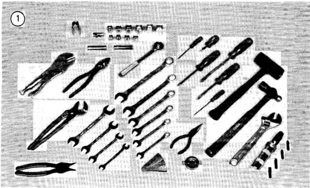
As a minimum, these include:
a. Combination wrenches
b. Sockets
c. Plastic mallet
d. Small hammer
e. Impact driver
f. Snap ring pliers
g. Gas pliers
h. Phillips screwdrivers
i. Slot (common) screwdrivers
j. Feeler gauges
k. Spark plug gauge
- Spark plug wrench
Special tools required are shown in the chapters covering the particular repair in which they are used.
Engine tune-up and troubleshooting procedures require other special tools and equipment. These are described in detail in the following sections.
EMERGENCY TOOL KITS
Highway
A small emergency tool kit kept on the bike is handy for road emergencies which otherwise could leave you stranded. The tools and spares listed below and shown in Figure 2 will let you handle most roadside repairs.
a. Motorcycle tool kit (original equipment)
b. Impact driver
c. Silver waterproof sealing tape (duct tape)
d. Hose-clamps (3 sizes)
e. Silicone sealer
f. Lock 'N' Seal
g. Flashlight
h. Tire patch kit
i. Tire irons
j. Plastic pint bottle (for oil)
k. Waterless hand cleaner
- Rags for clean up
Off-Road
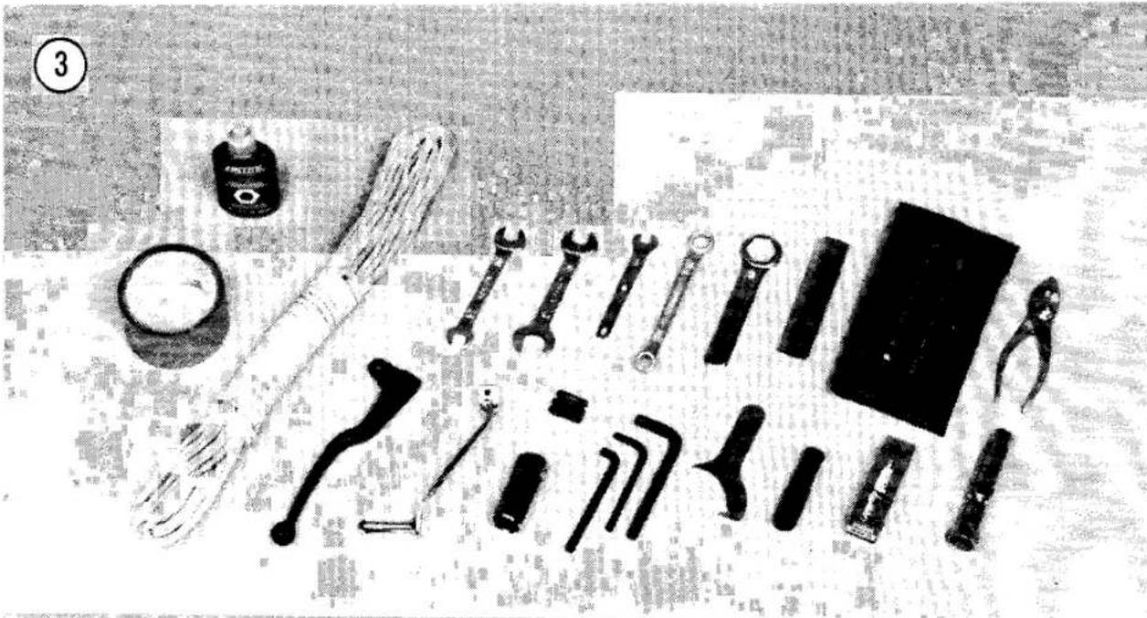
A few simple tools and aids carried on the motorcycle can mean the difference between walking or riding back to camp or to where repairs can be made. See Figure 3.
A few essential spare parts carried in your truck or van can prevent a day or weekend of trail riding from being spoiled. See Figure 4.

On the Motorcycle
a. Motorcycle tool kit (original equipment)
b. Drive chain master link
c. Tow line
d. Spark plug
e. Spark plug wrench
f. Shifter lever
g. Clutch/brake lever
h. Silver waterproof sealing tape (duct tape)
i. Loctite Lock 'N' Seal
In the Truck
a. Control cables (throttle, clutch, brake)
b. Silicone sealer
c. Tire patch kit
d. Tire irons
e. Tire pump
f. Impact driver
g. Oil
WARNING
Tools and spares should be carried on the motorcycle — not in clothing where a simple fall could result in serious injury from a sharp tool.
TROUBLESHOOTING AND TUNE-UP EQUIPMENT
Voltmeter, Ohmmeter, and Ammeter
For testing the ignition or electrical system, a good voltmeter is required. For motorcycle use, an instrument covering 0-20 volts is satisfactory. One which also has a 0-2 volt scale is necessary for testing relays, points, or individual contacts where voltage drops are much smaller. Accuracy should be ± ½ volt.
An ohmmeter measures electrical resistance. This instrument is useful for checking continuity (open and short circuits), and testing fuses and lights.
The ammeter measures electrical current. Ammeters for motorcycle use should cover 0-50 amperes and 0-250 amperes. These are useful for checking battery charging and starting current.
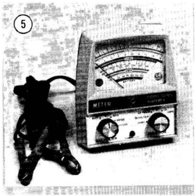
Several inexpensive vom's (volt-ohm-milliammeter) combine all three instruments into one which fits easily in any tool box. See Figure 5. However, the ammeter ranges are usually too small for motorcycle work.
Hydrometer
The hydrometer gives a useful indication of battery condition and charge by measuring the

specific gravity of the electrolyte in each cell. See Figure 6. Complete details on use and interpretation of readings are provided in the electrical chapter.
Compression Tester
The compression tester measures the compression pressure built up in each cylinder. The results, when properly interpreted, can indicate general cylinder, ring, and valve condition. See Figure 7. Extension lines are available for hard-to-reach cylinders.
Dwell Meter (Contact Breaker Point Ignition Only)
A dwell meter measures the distance in degrees of cam rotation that the breaker points remain closed while the engine is running. Since


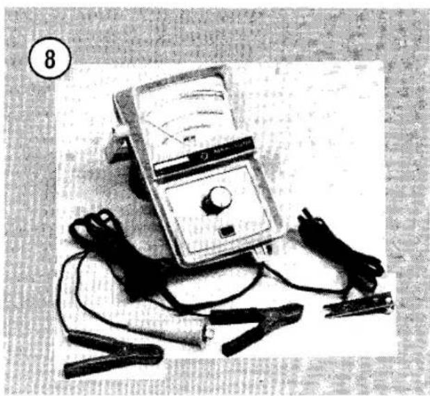

this angle is determined by breaker point gap, dwell angle is an accurate indication of breaker point gap.
Many tachometers intended for tuning and testing incorporate a dwell meter as well. See Figure 8. Follow the manufacturer's instructions to measure dwell.
Tachometer
A tachometer is necessary for tuning. See Figure 8. Ignition timing and carburetor adjustments must be performed at the specified idle speed. The best instrument for this purpose is one with a low range of 0-1,000 or 0-2,000 rpm for setting idle, and a high range of 0-4,000 or more for setting ignition timing at 3,000 rpm. Extended range (0-6,000 or 0-8,000 rpm) instruments lack accuracy at lower speeds. The instrument should be capable of detecting changes of 25 rpm on the low range.
NOTE: The motorcycle's tachometer is not accurate enough for correct idle adjustment.
Strobe Timing Light
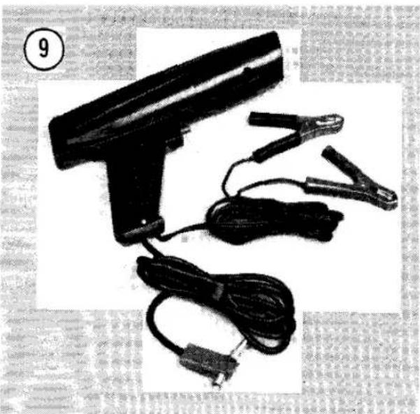
This instrument is necessary for tuning, as it permits very accurate ignition timing. The light flashes at precisely the same instant that No. 1 cylinder fires, at which time the timing marks on the engine should align. Refer to Chapter Three for exact location of the timing marks for your engine.
Suitable lights range from inexpensive neon bulb types (\2-3) to powerful xenon strobe lights (\20-40). See Figure 9. Neon timing lights are difficult to see and must be used in dimly lit areas. Xenon strobe timing lights can be used outside in bright sunlight.
Tune-up Kits
Many manufacturers offer kits that combine several useful instruments. Some come in a convenient carry case and are usually less expensive than purchasing one instrument at a time. Figure 10 shows one of the kits that is available. The prices vary with the number of instruments included in the kit.
Manometer (Carburetor Synchronizer)
A manometer is essential for accurately synchronizing carburetors on multi-cylinder engines. The instrument detects intake pressure differences between carburetors and permits them to be adjusted equally. A suitable manometer costs about \$25 and comes with detailed instructions for use. See Figure 11.
Fire Extinguisher
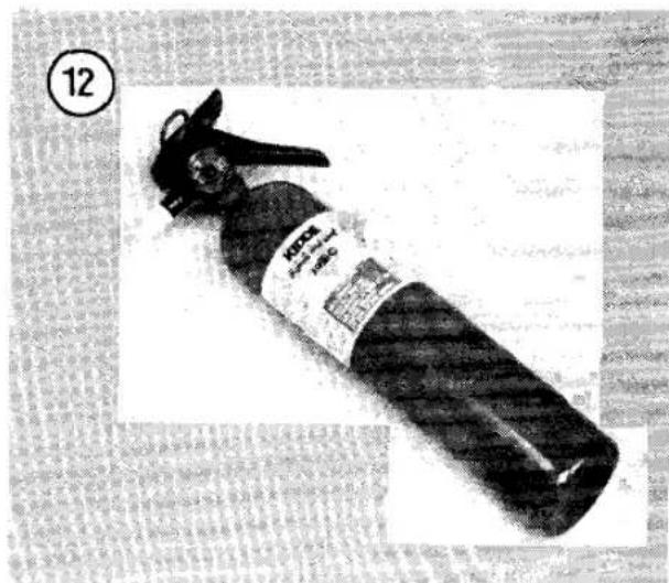
A fire extinguisher is a necessity when working on a vehicle. It should be rated for both Class B (flammable liquids — gasoline, oil, paint, etc.) and Class C (electrical — wiring, etc.) type fires. It should always be kept within reach. See Figure 12.

TROUBLESHOOTING
Troubleshooting motorcycle problems is relatively simple. To be effective and efficient, however, it must be done in a logical step-by-step manner. If it is not, a great deal of time may be wasted, good parts may be replaced unnecessarily, and the true problem may never be uncovered.
Always begin by defining the symptoms as closely as possible. Then, analyze the symptoms carefully so that you can make an intelligent guess at the probable cause. Next, test the probable cause and attempt to verify it; if it's not at fault, analyze the symptoms once again, this time eliminating the first probable cause. Continue on in this manner, a step at a time, until the problem is solved.
At first, this approach may seem to be time consuming, but you will soon discover that it's not nearly so wasteful as a hit-or-miss method that may never solve the problem. And just as important, the methodical approach to troubleshooting ensures that only those parts that are defective will be replaced.
The troubleshooting procedures in this chapter analyze typical symptoms and show logical methods for isolating and correcting trouble. They are not, however, the only methods; there may be several approaches to a given problem, but all good troubleshooting methods have one thing in common — a logical, systematic approach.
ENGINE
The entire engine must be considered when trouble arises that is experienced as poor performance or failure to start. The engine is more than a combustion chamber, piston, and crankshaft; it also includes a fuel delivery system, an ignition system, and an exhaust system.
Before beginning to troubleshoot any engine problems, it's important to understand an engine's operating requirements. First, it must have a correctly metered mixture of gasoline and air (Figure 1). Second, it must have an air-tight combustion chamber in which the mixture can be compressed. And finally, it requires a precisely timed spark to ignite the compressed mixture. If one or more is missing, the engine won't run, and if just one is deficient, the engine will run poorly at best.
Of the three requirements, the precisely timed spark — provided by the ignition system — is most likely to be the culprit, with gas/air mixture (carburetion) second, and poor compression the least likely.
STARTING DIFFICULTIES
Hard starting is probably the most common motorcycle ailment, with a wide range of problems likely. Before delving into a reluctant or non-starter, first determine what has changed
![graph TD A["1: Intake valve opens as piston begins downward, drawing air/fuel mixture into the cylinder, through the valve."] --> B["2: Compression: Intake valve closes and piston rises in cylinder, compressing air/fuel mixture."] B --> C["3: Power: Spark plug ignites compressed mixture, driving pis…](/content/2026/06/1280271/images/23022d139642cc709d81ab08a163e3ebd60f8fceee9fb177fc7384dbc23f132d.jpg)
since the motorcycle last started easily. For instance, was the weather dry then and is it wet now? Has the motorcycle been sitting in the garage for a long time? Has it been ridden many miles since it was last fueled?
Has starting become increasingly more difficult? This alone could indicate a number of things that may be wrong but is usually associated with normal wear of ignition and engine components.
While it's not always possible to diagnose trouble simply from a change of conditions, this information can be helpful and at some future time may uncover a recurring problem.
Fuel Delivery
Although it is the second most likely cause of trouble, fuel delivery should be checked first simply because it is the easiest.
First, check the tank to make sure there is fuel in it. Then, disconnect the fuel hose at the carburetor, open the valve and check for flow (Figure 2). If fuel does not flow freely make sure the tank vent is clear. Next, check for blockage in the line or valve. Remove the valve and clean it as described in the fuel system chapter.
If fuel flows from the hose, reconnect it and remove the float bowl from the carburetor, open the valve and check for flow through the float needle valve. If it does not flow freely when the float is extended and then shut off when the flow is gently raised, clean the carburetor as described in the fuel system chapter.
When fuel delivery is satisfactory, go on to the ignition system.
Ignition
Remove the spark plug from the cylinder and check its condition. The appearance of the plug is a good indication of what's happening in the combustion chamber; for instance, if the plug is wet with gas, it's likely that engine is flooded. Compare the spark plug to Figure 3. Make certain the spark plug heat range is correct. A "cold" plug makes starting difficult.
After checking the spark plug, reconnect it to the high-tension lead and lay it on the cylinder head so it makes good contact (Figure 4). Then, with the ignition switched on, crank the engine several times and watch for a spark across the plug electrodes. A fat, blue spark should be visible. If there is no spark, or if the spark is weak, substitute a good plug for the old one and check again. If the spark has improved, the old plug is faulty. If there was no change, keep looking.
Make sure the ignition switch is not shorted to ground. Remove the spark plug cap from the end of the high-tension lead and hold the exposed end of the lead about 1/8 inch from the cylinder head. Crank the engine and watch for a spark arcing from the lead to the head. If it's satisfactory, the connection between the lead and the cap was faulty. If the spark hasn't improved, check the coil wire connections.
If the spark is still weak, remove the ignition cover and remove any dirt or moisture from the points or sensor. Check the point or air gap against the specifications in the Quick Reference Data at the beginning of the book.
If spark is still not satisfactory, a more serious problem exists than can be corrected with simple adjustments. Refer to the electrical system chapter for detailed information for correcting major ignition problems.
Compression
Compression — or the lack of it — is the least likely cause of starting trouble. However, if compression is unsatisfactory, more than a simple adjustment is required to correct it (see the engine chapter).
An accurate compression check reveals a lot about the condition of the engine. To perform this test you need a compression gauge (see Chapter One). The engine should be at operating temperature for a fully accurate test, but even a cold test will reveal if the starting problem is compression.
Remove the spark plug and screw in a compression gauge (Figure 5). With assistance, hold the throttle wide open and crank the engine several times, until the gauge ceases to rise. Normal compression should be 130-160 psi, but a reading as low as 100 psi is usually sufficient for the engine to start. If the reading is much lower than normal, remove the gauge and pour about a tablespoon of oil into the cylinder.
②
![graph TD A["Check tank for gas"] --> B["EMPTY"] A --> C["FULL"] B --> D["Fill"] C --> E["Disconnect line at carburetor and check for flow"] D --> F["NO FUEL FLOW"] E --> G["FUEL FLOW"] F --> H["Fuel tank"] G --> I["Carburetor"] H --> J["Remove and clean fuel tank valve (see Fuel System chapter)"] I…](/content/2026/06/1280271/images/e517328e2023653afc21de06a7adf26af83139f7baf153ded46596b535559d64.jpg)
NOTE: If fuel flow is adequate and spark is present (see Ignition which follows), increase fuel ratio with idle screw.
3
NORMAL
- Appearance—Firing tip has deposits of light gray to light tan.
- Can be cleaned, regapped and reused.
CARBON FOULED
- Appearance—Dull, dry black with fluffy carbon deposits on the insulator tip, electrode and exposed shell.
- Caused by—Fuel/air mixture too rich, plug heat range too cold, weak ignition system, dirty air cleaner, faulty automatic choke or excessive idling.
- Can be cleaned, regapped and reused.
OIL FOULED
- Appearance—Wet black deposits on insulator and exposed shell.
- Caused by—Excessive oil entering the combustion chamber through worn rings, pistons, valve guides or bearings.
- Replace with new plugs (use a hotter plug if engine is not repaired).
LEAD FOULED
• Appearance — Yellow insulator deposits (may sometimes be dark gray, black or tan in color) on the insulator tip.
- Caused by—Highly leaded gasoline.
- Replace with new plugs
LEAD FOULED
- Appearance--Yellow glazed deposits indicating melted lead deposits due to hard acceleration.
- Caused by—Highly leaded gasoline.
- Replace with new plugs
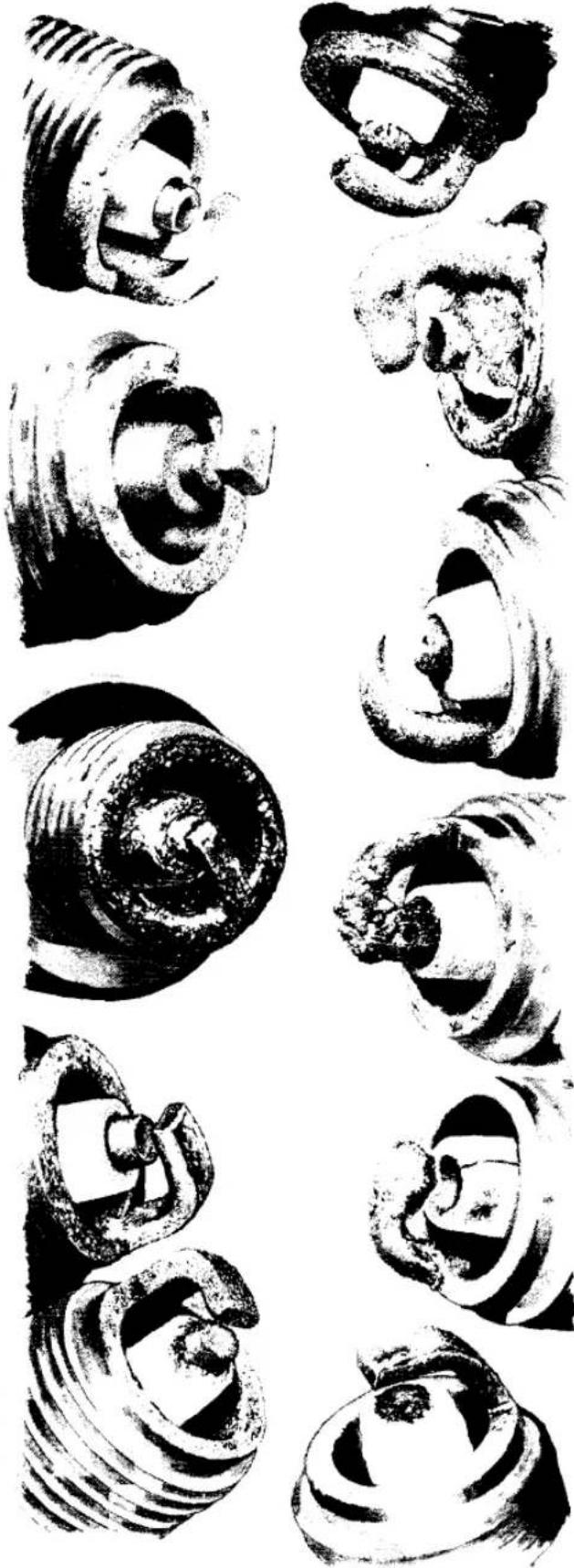
OIL AND LEAD FOULED
- Appearance—Glazed yellow deposits with a slight brownish tint on the insulator tip and ground electrode.
-Replace with new plugs.
FUEL ADDITIVE RESIDUE
Appearance — Brown colored hardened ash deposits on the insulator tip and ground electrode.
Caused by—Fuel and/or oil additives.
-Replace with new plugs.
WORN
Appearance — Severely worn or eroded electrodes.
Caused by--Normal wear or unusual oil and/or fuel additives.
-Replace with new plugs
PREIGNITION
• Appearance - Meited ground electrode.
- Caused by—Overadvanced ignition timing, inoperative ignition advance mechanism, too low of a fuel octane rating, lean fuel/air mixture or carbon deposits in combustion chamber.
PREIGNITION
• Appearance—Melted center electrode.
- Caused by—Abnormal combustion due to overadvanced ignition timing or incorrect advance, too low of a fuel octane rating, lean fuel/air mixture, or carbon deposits in combustion chamber.
- Correct engine problem and replace with new plugs.
INCORRECT HEAT RANGE
• Appearance—Melted center electrode and white blistered insulator tip.
- Caused by—Incorrect plug heat range selection.
-Replace with new plugs

![graph TD A["IGNITION: Turn switches on. Remove spark plug and check for spark outside cylinder"] --> B["SPARK"] A --> C["NO SPARK"] B --> D["Check with good plug"] C --> E["Check high tension lead"] D --> F["SPARK"] E --> G["SPARK"] F --> H["No SPARK"] G --> I["Check coil connections"] H --> I I -->…](/content/2026/06/1280271/images/1fda8bbbe12869e9e77e4d65b82dc8743ac2b33a10dd4e169ce6e327fa8cea21.jpg)

Crank the engine several times to distribute the oil and test the compression once again. If it is now significantly higher, the rings and bore are worn. If the compression did not change, the valves are not seating correctly. Adjust the valves and check again. If the compression is still low, refer to the engine chapter.
NOTE: Low compression indicates a developing problem. The condition causing it should be corrected as soon as possible.
POOR PERFORMANCE
Poor engine performance can be caused by any of a number of things related to carburetion, ignition, and the condition of the sliding and rotating components in the engine. In addition, components such as brakes, clutch, and transmission can cause problems that seem to be related to engine performance, even when the engine is in top running condition.
Poor Idling
Idling that is erratic, too high, or too low is most often caused by incorrect adjustment of the carburetor idle circuit. Also, a dirty air filter or an obstructed fuel tank vent can affect idle speed. Incorrect ignition timing or worn or faulty ignition components are also good possibilities.
First, make sure the air filter is clean and correctly installed. Then, adjust the throttle cable free play, the throttle stop screw, and the idle mixture air screw (Figure 6) as described in the routine maintenance chapter.
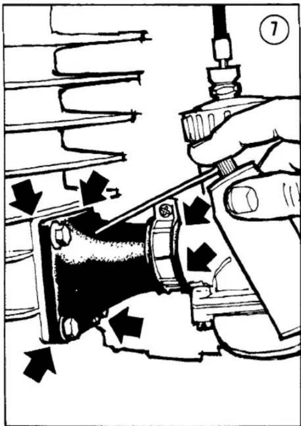
If idling is still poor, check the carburetor and manifold mounts for leaks; with the engine warmed up and running, spray WD-40 or a similar light lube around the flanges and joints of the carburetor and manifold (Figure 7). Listen for changes in engine speed. If a leak is present, the idle speed will drop as the lube “plugs” the leak and then pick up again as it is drawn into the engine. Tighten the nuts and clamps and test again. If a leak persists, check for a damaged gasket or a pinhole in the manifold. Minor leaks in manifold hoses can be repaired with silicone sealer, but if cracks or holes are extensive, the manifold should be replaced.
A worn throttle slide may cause erratic running and idling, but this is likely only after many thousands of miles of use. To check, remove the carburetor top and feel for back and forth movement of the slide in the bore; it should be barely perceptible. Inspect the slide for large worn areas and replace it if it is less than perfect (Figure 8).
If the fuel system is satisfactory, check ignition timing and breaker point gap (air gap in electronic ignition). Check the condition of the system components as well. Ignition-caused idling problems such as erratic running can be the fault of marginal components. See the electrical system chapter for appropriate tests.
Rough Running or Misfiring
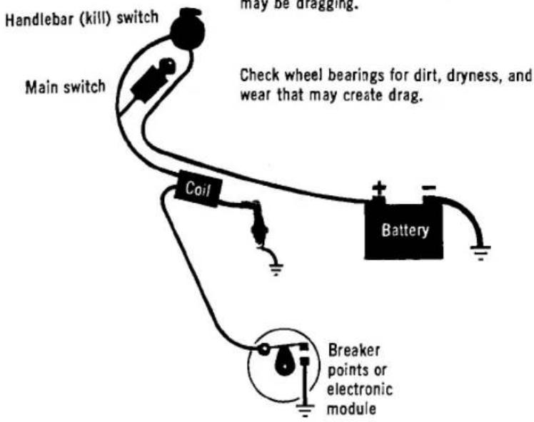
Misfiring (see Figure 9) is usually caused by an ignition problem. First, check all ignition connections (Figure 10). They should be clean, dry, and tight. Don't forget the kill switch; a loose connection can create an intermittent short.


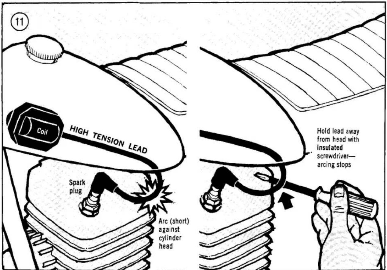
Check the insulation on the high-tension spark plug lead. If it is cracked or deteriorated it will allow the spark to short to ground when the engine is revved. This is easily seen at night. If arcing occurs, hold the affected area of the wire away from the metal to which it is arcing, using an insulated screwdriver (Figure 11), and see if the misfiring ceases. If it does, replace the high-tension lead. Also check the connection of the spark plug cap to the lead. If it is poor, the spark will break down at this point when the engine speed is increased.
The spark plug could also be poor. Test the system with a new plug.
Incorrect point gap or a weak contact breaker spring can cause misfiring. Check the gap and the alignment of the points. Push the moveable arm back and check for spring tension (Figure 12). It should feel stiff.
On models with electronic ignition, have the electronic module tested by a dealer or substitute a known good unit for a suspected one.
If misfiring occurs only at a certain point in engine speed, the problem may very likely be

![graph TD A["Top Section"] --> B["Slide needle"] B --> C["Air jet"] C --> D["Pilot air screw"] D --> E["Fuel"] E --> F["Main jet"] F --> G["Pilot jet"] G --> H["Mid-Range"] H --> I["Needle jet"] I --> J["HIGH-SPEED"] style A fill:#f9f,stroke:#333 style B fill:#ccf,stroke:#333 style C fill:#cfc,stroke…](/content/2026/06/1280271/images/b45f2b61d477a65150786cdf7a2f48ddba9b92fafdd483d720cd7d3fe9584013.jpg)

14
Gradual

LOSS OF POWER
Check ignition and carburetion and tune engine if necessary.
Check compression. If compression rises following wet test, ring and cylinder wear is indicated. If compression remains low during wet test, valve and seat wear are indicated.
Check brake adjustment and condition; they may be dragging.
Sudden
Check compression (above). If power loss is sudden, damage to rings, piston, and bore or valves and seats are more likely than wear.

Check the ignition system for a failed component, poor contact, or change in timing or point gap. Check electronic module on electronic ignition.
Check the fuel system for an obstruction.
carburetion. Poor performance at idle is described earlier. Misfiring at low speed (just above idle) can be caused by a dirty low-speed circuit or jet (Figure 13). Poor midrange performance is attributable to a worn or incorrectly adjusted needle and needle jet. Misfiring at high speed (if not ignition related) is usually caused by a too-large main jet which causes the engine to run rich. Any of these carburetor-related conditions can be corrected by first cleaning the carburetor and then adjusting it as described in the tune-up and maintenance chapter.
Loss of Power
First determine how the power loss developed (Figure 14). Did it decline over a long period of time or did it drop abruptly? A gradual loss is normal, caused by deterioration of the engine's state of tune and the normal wear of the cylinder and piston rings and the valves and seats. In such case, check the condition of the

ignition and carburetion and measure the compression as described earlier.
A sudden power loss may be caused by a failed ignition component, obstruction in the fuel system, damaged valve or seat, or a broken piston ring or damaged piston (Figure 15).
If the engine is in good shape and tune, check the brake adjustment. If the brakes are dragging, they will consume considerable power. Also check the wheel bearings. If they are dry, extremely dirty, or badly worn they can create considerable drag.
Engine Runs Hot
A modern motorcycle engine, in good mechanical condition, correctly tuned, and operated as it was intended, will rarely experience overheating problems. However, out-of-spec conditions can create severe overheating that may result in serious engine damage. Refer to Figure 16.

Overheating is difficult to detect unless it is extreme, in which case it will usually be apparent as excessive heat radiating from the engine, accompanied by the smell of hot oil and sharp, snapping noises when the engine is first shut off and begins to cool.
Unless the motorcycle is operated under sustained high load or is allowed to idle for long periods of time, overheating is usually the result of an internal problem. Most often it's caused by a too-lean fuel mixture.
Remove the spark plug and compare it to Figure 3. If a too-lean condition is indicated, check for leaks in the intake manifold (see Poor Idling). The carburetor jetting may be incorrect but this is unlikely if the overheating problem has just developed (unless, of course, the engine was jetted for high altitude and is now being run near sea level). Check the slide needle in the carburetor to make sure it hasn't come loose and is restricting the flow of gas through the main jet and needle jet (Figure 17).
Check the ignition timing; extremes of either advance or retard can cause overheating.
Piston Seizure and Damage
Piston seizure is a common result of overheating (see above) because an aluminum piston expands at a greater rate than a steel cylinder. Seizure can also be caused by piston-to-cylinder clearance that is too small; ring end gap that is too small; insufficient oil; spark plug heat range too hot; and broken piston ring or ring land.
A major piston seizure can cause severe engine damage. A minor seizure — which usually subsides after the engine has cooled a few minutes — rarely does more than scuff the piston skirt the first time it occurs. Fortunately, this condition can be corrected by dressing the piston with crocus cloth, refitting the piston and rings to the bore with recommended clearances, and checking the timing to ensure overheating does not occur. Regard that first seizure as a warning and correct the problem before continuing to run the engine.
CLUTCH AND TRANSMISSION
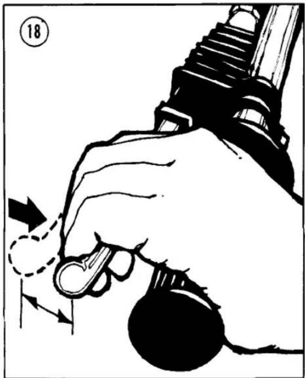
- Clutch slips—Make sure lever free play is sufficient to allow the clutch to fully engage

(Figure 18). Check the contact surfaces for wear and glazing. Transmission oil additives also can cause slippage in wet clutches. If slip occurs only under extreme load, check the condition of the springs or diaphragm and make sure the clutch bolts are snug and uniformly tightened.
-
Clutch drags—Make sure lever free play isn't so great that it fails to disengage the clutch. Check for warped plates or disc. If the transmission oil (in wet clutch systems) is extremely dirty or heavy, it may inhibit the clutch from releasing.
-
Transmission shifts hard—Extremely dirty oil can cause the transmission to shift hard.
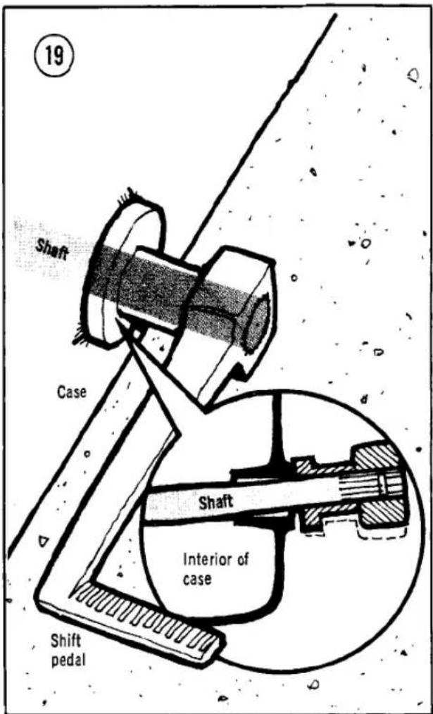
Check the selector shaft for bending (Figure 19). Inspect the shifter and gearsets for wear and damage.
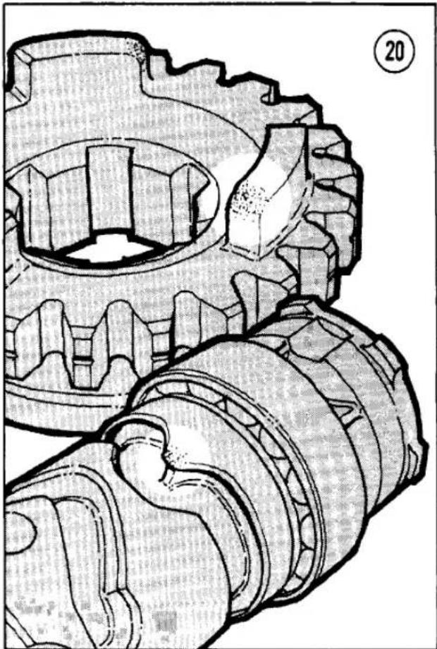
- Transmission slips out of gear—This can be caused by worn engagement dogs or a worn or damaged shifter (Figure 20). The overshift travel on the selector may be misadjusted.
- Transmission is noisy—Noises usually indicate the absence of lubrication or wear and damage to gears, bearings, or shims. It's a good idea to disassemble the transmission and carefully inspect it when noise first occurs.
DRIVE TRAIN
Drive train problems (outlined in Figure 21) arise from normal wear and incorrect maintenance.
CHASSIS
Chassis problems are outlined in Figure 22.
- Motorcycle pulls to one side—Check for loose suspension components, axles, steering

21
DRIVE SYSTEM

TRANSMISSION SHIFTS HARD

Check for bent selector shaft

Inspect selector and gearsets for wear
TRANSMISSION SLIPS OUT OF GEAR

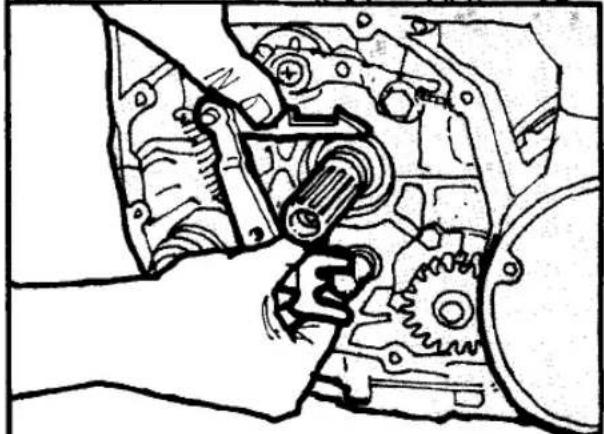
Check overshift travel and increase if insufficient
TRANSMISSION IS NOISY
Check oil level
Disassemble and inspect (see Transmission chapter)


SUSPENSION AND HANDLING
Suspension nuts and bolts

Steering head adjustment

Check for dented or damaged slider
Align fork sliders

SUSPENSION AND HANDLING CONTINUED


SUSPENSION AND HANDLING CONTINUED
![graph TD A["STEERING IS TIGHT OR NOTCHY\nInspect, lubricate, and adjust steering head"] --> B["REAR SUSPENSION STICKS\nReplace shock with bent rod"] B --> C["IMPACT"] C --> D["STEERING IS SLOPPY\nInspect, lubricate, and adjust steering head"] D --> E["Rear SUSPENSION WON'T DAMP\nCheck for oil\nRebui…](/content/2026/06/1280271/images/4bf0de331849c39ee3c0b04706739ebbce7b797fbdce64df4623f7c7c99c8b97.jpg)
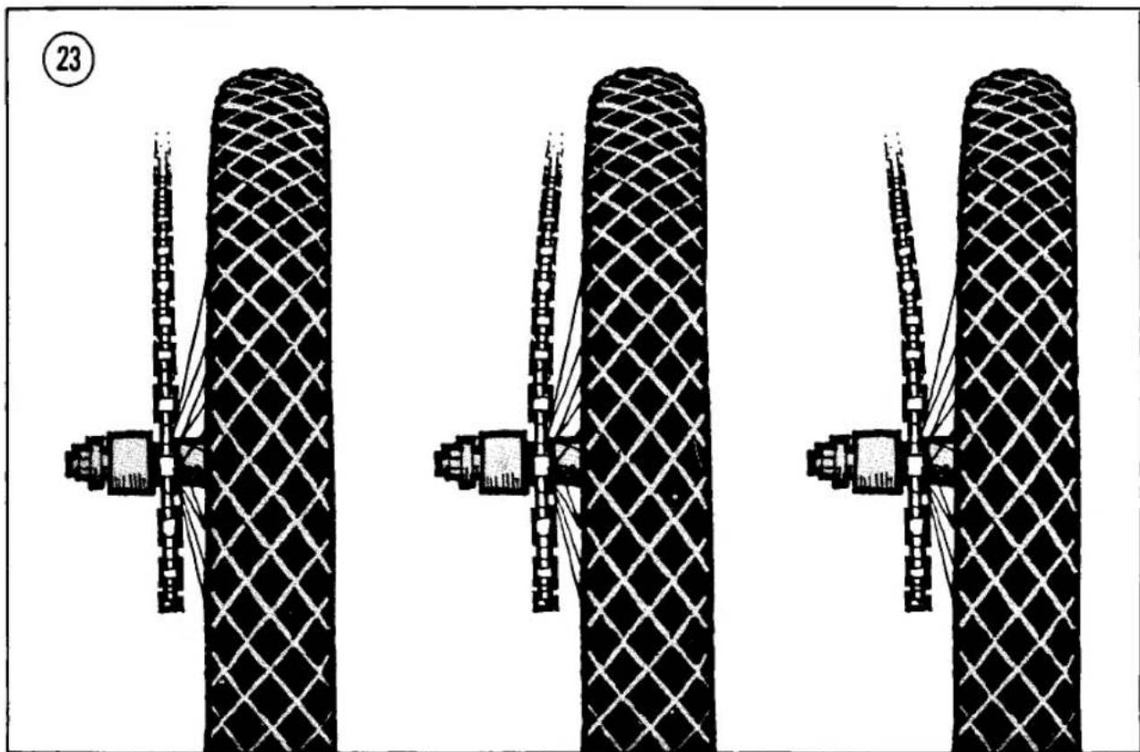

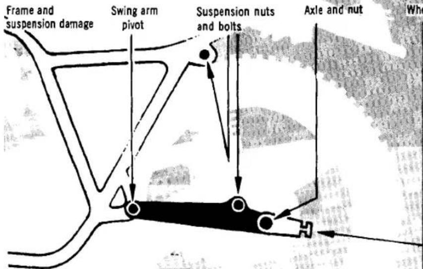
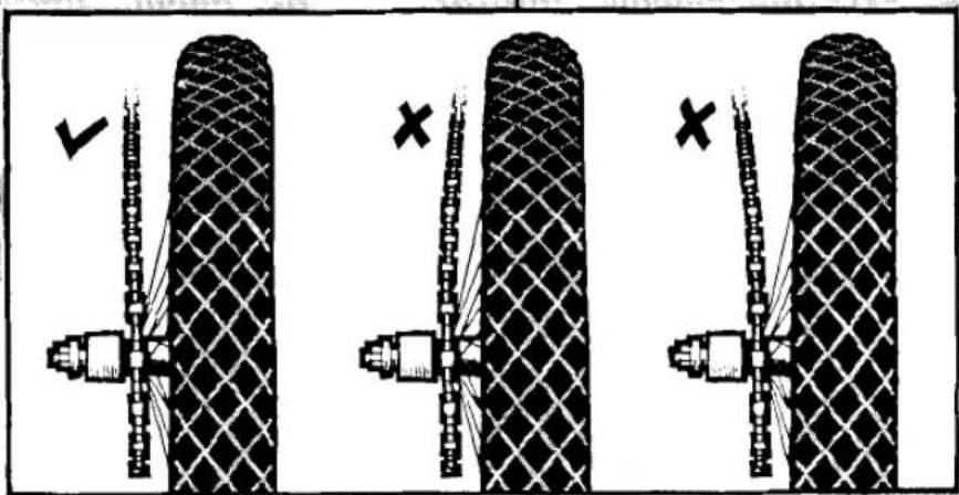
head, swing arm pivot. Check wheel alignment (Figure 23). Check for damage to the frame and suspension components.
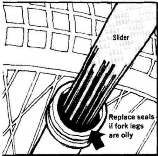
- Front suspension doesn't damp—This is most often caused by a lack of damping oil in the fork legs. If the upper fork tubes are exceptionally oily, it's likely that the seals are worn out and should be replaced.
- Front suspension sticks or won't fully compress—Misalignment of the forks when the wheel is installed can cause this. Loosen the axle nut and the pinch bolt on the nut end of the axle (Figure 24). Lock the front wheel with the brake and compress the front suspension several times to align the fork legs. Then, tighten the pinch bolt and then the axle nut.
The trouble may also be caused by a bent or dented fork slider (Figure 25). The distortion required to lock up a fork tube is so slight that it is often impossible to visually detect. If this type of damage is suspected, remove the fork leg and remove the spring from it. Attempt to operate the fork leg. If it still binds, replace the slider; it's not practical to repair it.
- Rear suspension does not damp—This is usually caused by damping oil leaking past

worn seals. Rebuildable shocks should be refitted with complete service kits and fresh oil. Non-rebuildable units should be replaced.
- Rear suspension sticks—This is commonly caused by a bent shock absorber piston rod (Figure 26). Replace the shock; the rod can't be satisfactorily straightened.
- Steering is tight or "notchy"—Steering head bearings may be dry, dirty, or worn. Adjustment of the steering head bearing pre-load may be too tight.
- Steering is sloppy—Steering head adjustment may be too loose. Also check the swing arm pivot; looseness or extreme wear at this point translate to the steering.
BRAKES
Brake problems arise from wear, lack of maintenance, and from sustained or repeated exposure to dirt and water.
- Brakes are ineffective—Ineffective brakes are most likely caused by incorrect adjustment. If adjustment will not correct the problem, remove the wheels and check for worn or glazed linings. If the linings are worn beyond the service limit, replace them. If they are simply glazed, rough them up with light sandpaper.
In hydraulic brake systems, low fluid levels can cause a loss of braking effectiveness, as can worn brake cylinder pistons and bores. Also check the pads to see if they are worn beyond the service limit. - Brakes lock or drag—This may be caused by incorrect adjustment. Check also for foreign matter embedded in the lining and for dirty and dry wheel bearings.
ELECTRICAL SYSTEM
Many electrical system problems can be easily solved by ensuring that the affected connections are clean, dry, and tight. In battery equipped motorcycles, a neglected battery is the source of a great number of difficulties that could be prevented by simple, regular service to the battery.
A multimeter, like the volt/ohm/milliammeter described in Chapter One, is invaluable for efficient electrical system troubleshooting.
See Figures 27 and 28 for schematics showing


Ground connection
Primary circuit

Secondary circuit

ELECTRONIC SYSTEM
Primary resistor
![graph TD A["Engine run"] --> B["Engine start"] B --> C["Ignition switch"] C --> D["Battery"] D --> E["Ignition coil"] E --> F["Electronic module"] F --> G["Pole piece"] H["Spark plug"] --> I["Trigger wheel"] I --> J["Ground"]](/content/2026/06/1280271/images/b9dd7dc2790a06cc3c3486fc0a5c97e6cfc107f59ebc7b18552b37ce6b5fe9af.jpg)
simplified conventional and electronic ignition systems. Typical and most common electrical troubles are also described.
CHARGING SYSTEM
-
Battery will not accept a charge—Make sure the electrolyte level in the battery is correct and that the terminal connections are tight and free of corrosion. Check for fuses in the battery circuit. If the battery is satisfactory, refer to the electrical system chapter for alternator tests. Finally, keep in mind that even a good alternator is not capable of restoring the charge to a severely discharged battery; it must first be charged by an external source.
-
Battery will not hold a charge—Check the battery for sulfate deposits in the bottom of the case (Figure 29). Sulfation occurs naturally and the deposits will accumulate and eventually come in contact with the plates and short them out. Sulfation can be greatly retarded by keeping the battery well charged at all times. Test the battery to assess its condition.
If the battery is satisfactory, look for excessive draw, such as a short.
LIGHTING
Bulbs burn out frequently—All bulbs will eventually burn out, but if the bulb in one particular light burns out frequently check the light assembly for looseness that may permit excessive vibration; check for loose connections that could cause current surges; check also to make sure the bulb is of the correct rating.
FUSES
Fuse blows—When a fuse blows, don't just replace it; try to find the cause. Consider a fuse a warning device as well as a safety device. And never replace a fuse with one of greater amperage rating. It probably won't melt before the insulation on the wiring does.
WIRING
Wiring problems should be corrected as soon as they arise — before a short can cause a fire that may seriously damage or destroy the motorcycle.
A circuit tester of some type is essential for locating shorts and opens. Use the appropriate wiring diagram at the end of the book for reference. If a wire must be replaced make a notation on the wiring diagram of any changes in color coding.

CHAPTER THREE

LUBRICATION, MAINTENANCE AND TUNE-UP
This chapter covers all the regular maintenance you have to perform to keep your machine in top shape.
Regular maintenance is the best guarantee of a trouble-free, long lasting motorcycle. In addition, while performing the routine jobs, you will probably notice any other developing problems at an early stage when they are simple and inexpensive to correct.
Table 1 is a recommended minimum maintenance schedule (Tables 1-6 are at the end of the chapter). However, you will have to determine your own maintenance requirements based on the type of riding you do and the place you ride. If you ride in dusty areas or at high speeds or if you make a lot of short 10 or 15 minute rides, service the items more often. Perform the maintenance at each TIME or MILEAGE interval, whichever comes first.
NOTE
If you have a brand new motorcycle, we recommend you take the bike to your dealer for the initial break-in maintenance at 500 miles (800 km).
EMISSION CONTROLLED MOTORCYCLES
This manual covers both U.S. emission controlled motorcycles and non-controlled motorcycles.
If your motorcycle is emission controlled, we urge you to follow all procedures specifically designated for your bike. If you don't follow the maintenance schedule in this manual or if you alter engine parts or change their settings from the standard factory specifications (ignition timing, carburetor idle mixture, exhaust system, etc.), your bike may not comply with government emissions standards.
In addition, since most emission controlled bikes are carburetted with a lean fuel/air mixture, any changes to emission-related parts (such as exhaust system modifications) could cause the engine to run so lean that engine damage would result.
MODEL IDENTIFICATION
In the process of building motorcycles, the factory often introduces new models throughout the calendar year. New models,
when introduced, are not necessarily identified by year but by model number suffix. See Table 2 at the end of this chapter for model year and model suffix equivalents.
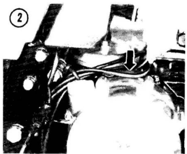
When you need to order parts for your motorcycle, make sure you get the right ones. Note the frame serial number on the steering head (Figure 1) and the engine serial number on the engine cases (Figure 2). Your dealer will often need these numbers to get the right parts for your bike.
BATTERY
The battery electrolyte level should be checked regularly, particularly during hot weather. Motorcycle batteries are marked with electrolyte level limit lines (Figure 3). Always maintain the fluid level between the lines, adding distilled water as required. Distilled water is available at most supermarkets and its use will prolong the life of the battery, especially in areas where tap water is hard (has a high mineral content).
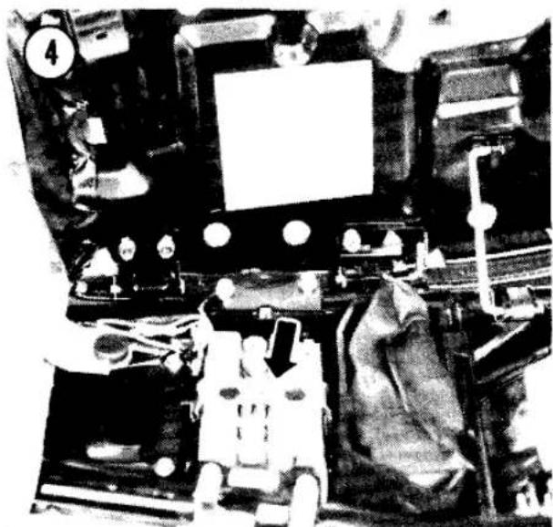
Inspect the fluid level in all the cells. The battery is under the seat (Figure 4). Refer to Battery in Chapter Eight before removing the battery from the motorcycle.
WARNING
Battery electrolyte contains sulfuric acid, which can destroy clothing and cause serious chemical burns. Electrolyte splashed into the eyes is extremely dangerous; wear safety glasses. In case of contact, flood with cool water for about 5 minutes and call a doctor immediately if the eyes were exposed.
Don't overfill the battery or you'll lose some electrolyte, weakening the battery and causing corrosion. Never allow the electrolyte level to drop below the top of the plates, or the plates may be permanently damaged.
CAUTION
If electrolyte is spilled on the motorcycle, wash it off immediately with plenty of water.



ENGINE OIL AND FILTER
Oil Level Inspection
- Wait several minutes after shutting off the engine before making the check, to give all oil enough time to run down into the crankcase.
- Put the bike on its centerstand (or hold it level).
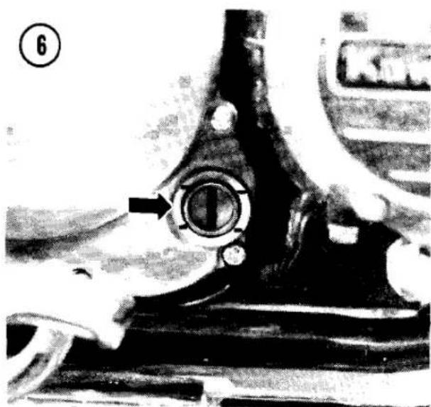
- Look at the oil inspection window near the bottom of the right engine cover (A, Figure 5). The oil level should lie between the upper and lower lines at the window (Figure 6).
- If the oil level is below the lower line, remove the filler cap and add oil slowly, in small quantities, through the filler hole (B, Figure 5). Add enough to raise the oil level up to (but not above) the top line. Be sure to give the oil enough time to run down into the crankcase before rechecking the level in the inspection window. Use SAE 10W40, 10W50, 20W40 or 20W50 motor oil marked for service "SE" or better.
- Install the filler cap.
Oil and Filter Change
Change the oil according to the maintenance schedule (Table 1). The filter should be changed every other oil change. If you ride hard or in dusty areas or if you take a lot of short trips, change the oil more frequently.
Try to stay with one brand of oil. The use of oil additives is not recommended; anything you add to the engine oil also gets on the clutch plates and could cause clutch slippage or damage.
- Ride the bike to warm it up fully, then turn it off.
- Put the bike up on its centerstand.
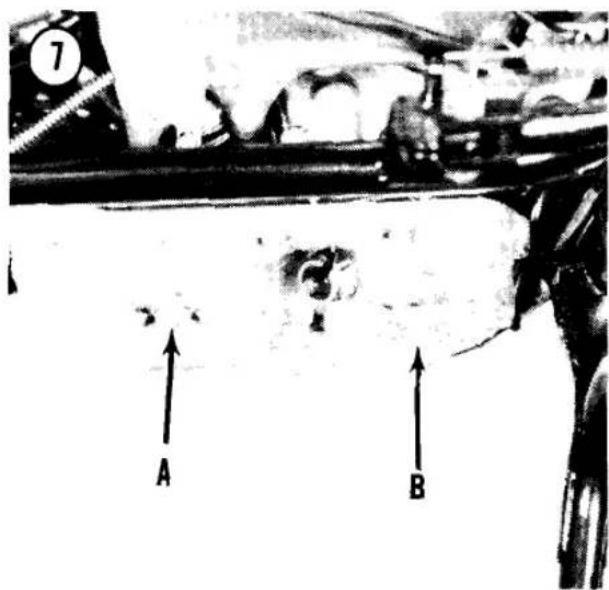
- Put a drain pan under the crankcase and remove the drain plug (A, Figure 7). After the oil has drained, install the drain plug and torque it to 27 ft.-lb. (3.8 mkg).
- The oil filter should be replaced every other engine oil change. If you are not changing the filter, skip to Step 10.
- To remove the oil filter, unscrew the filter cover bolt (B, Figure 7).



- Remove the cover and filter, discard the filter and clean the cover and the bolt. Inspect the O-rings on the cover and on the filter bolt (Figure 8). Replace them if damaged.
- Insert the bolt into the cover and install the filter cup, spring, washer and cover plate (Figure 9).
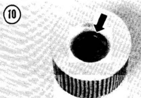
- Check that the oil filter grommets are in place at both ends of the filter (Figure 10) and turn the filter onto the filter bolt.
NOTE
Before installing the cover, clean off the mating surface of the crankcase—do not allow any road dirt to enter the oil system.
-
Install the filter assembly in the crankcase and torque the filter bolt to 15 ft.-lb. (2.0 mkg). 10. Remove the oil filler cap and add the specified oil until it just reaches the upper line at the inspection window. Be sure to give the oil enough time to run down into the crankcase before checking the level in the inspection window.
-
Screw in the filler cap and start the engine; let it idle and check for leaks.
- Turn off the engine and recheck for the correct oil level.
GENERAL LUBRICATION
The following items should be lubricated according to the maintenance schedule (Table

1) and after cleaning the motorcycle. Special lubricants are available for control cables and other applications, but regular lubrication is more important than the type of lubricant you use: oil, grease, WD40, LPS3, etc.
Control Cables
The most positive method of control cable lubrication involves the use of a lubricator like the one shown in Figure 11. Disconnect the cable at the lever, attach the lubricator and inject lubricant into the cable sheath until it runs out of the other end. When lubricating a throttle cable with this type of device, the other end of the cable should first be disconnected from the carburetor.
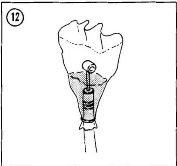
If you do not have a lubricator, make a funnel from stiff paper or a plastic bag and tape it securely to one end of the cable (Figure 12). Hold the cable upright and add lubricant to the funnel. Work the cable in and out to help the lubricant work down the cable.
Control Pivots
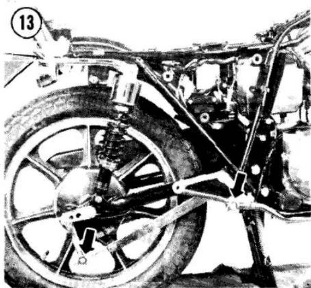
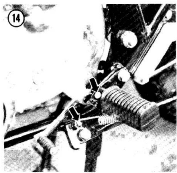
Lubricate the brake pedal and linkage pivots (Figure 13), the footpeg, sidestand and centerstand pivots (Figure 14) and the control lever pivots and control cable ends (Figure 15).
Throttle Grip
- Remove the screws that assemble the twist grip housing. Raise the top half of the housing.
CAUTION
Be careful not to cut the kill switch wires on the edge of the throttle grip housing.
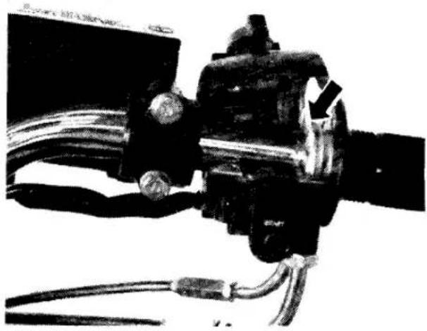
- Slide the grip back and grease the handlebar under the grip and the cable end (Figure 16).
- Reassemble the twist grip housing, fitting the upper housing peg into the hole in the handlebar. Check that the grip works smoothly.
Speedometer/Tachometer Cables
Disconnect the cables at the lower end. Pull the inner cable out, apply a light coat of grease and reinstall the cables. You may have to rotate the wheel to allow the speedometer cable to seat. If the tachometer cable won't seat, rotate the engine with the starter. Tighten the cable fasteners securely.
Ignition Advance
To lubricate the ignition advance mechanism, refer to Ignition Advance in Chapter Four.
CLUTCH ADJUSTMENT
Clutch Lever Play
The clutch cable should have about 1/8 in. (2-3 mm) play at the cable end of the lever before the clutch starts to disengage (Figure 17). Minor adjustments can be made at the hand lever; loosen the locknut, turn the adjuster as required and tighten the locknut.
According to the maintenance schedule (Table 1) and whenever the hand lever adjustment range is used up, adjust the clutch release as described here.
Clutch Release Adjustment
As the clutch cable stretches, cable play will exceed the range of the cable adjusters. As the clutch plates and discs inside the engine wear, the clutch release must be adjusted even when the cable play is within tolerance or the clutch can drag and cause rapid wear. Adjust the clutch as follows.
- In front of the engine, loosen the clutch mid-cable adjuster locknut and shorten the adjuster all the way (Figure 18).
16
17


- At the clutch lever, loosen the locknut and turn the adjuster until 3/16-1/4 in. (5-6 mm) of threads are showing between the locknut and the adjuster body (Figure 19).
- Remove the 2 clutch adjuster cover screws and the cover (Figure 20).
- Loosen the locknut (Figure 21), then turn the screw out until it turns freely.
- Turn the screw in until it just becomes hard to turn. Then turn the screw out 1/2 turn. Hold the screw in position and tighten the locknut.
- In front of the engine, lengthen the mid-cable adjuster until it has just taken all the slack out of the cable and the clutch lever has no free play. Tighten the locknut.
- Check that the lower end of the clutch cable (below the engine) is fully seated in its socket.
- At the clutch lever, turn the adjuster as required to get about 1/8 in. (2-3 mm) of cable play at the clutch lever.
- Install the clutch adjuster cover.
DRIVE CHAIN
Clean, lubricate, adjust and check the drive chain for wear according to the maintenance schedule (Table 1). The drive chain is endless (it has no master link) for maximum strength.
Chain Lubrication
Many lubricants are available that are specially formulated for drive chains. If a special lubricant is not available, Kawasaki recommends SAE 90 gear oil for chain lubrication; it is less likely to be thrown off the chain than lighter oils.
NOTE
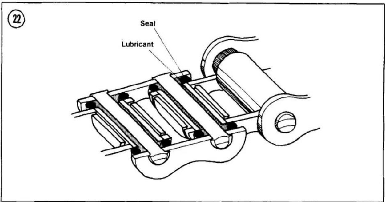
The drive chain has a permanent internal bushing lubricant sealed in by O-rings between the side plates (Figure 22). Do not use a solvent or aerosol lubricant not designed for use on O-rings.
Chain Play Inspection
The drive chain must have adequate play so that the chain is not strung tight when the swing arm is horizontal (when the rider is seated). On the other hand, too much play may cause the
chain to jump off the sprockets with potentially disasterous results.
- Put the motorcycle on its centerstand.
- Turn the rear wheel slowly until you locate the part of chain that stretches tightest between the 2 sprockets on the bottom chain run (the chain wears unevenly).
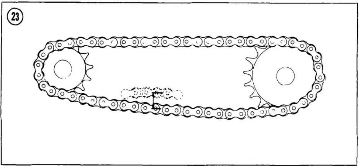
- With thumb and forefinger, lift up and press down the chain at that point, measuring the distance the chain moves vertically. The chain should have about 1 in. (25 mm) of vertical travel at midpoint (Figure 23). If it has less than 1 in. (20 mm) or more than 1 3/8 in. (35 mm) of travel, adjust the chain play.
Adjustment
When adjusting the drive chain, you must also maintain rear wheel alignment. A misaligned rear wheel can cause poor handling and pulling to one side or the other, as well as increased chain, sprocket and tire wear. All models have wheel alignment marks on the swing arm and chain adjusters. If the alignment marks are kept at the same position left and right, the rear wheel should be aligned correctly.
-
Remove the rear axle nut cotter pin and remove the axle nut (A, Figure 24).
-
Loosen the rear torque link nut (B, Figure 24).
- Loosen the locknuts on both chain adjusters (C, Figure 24).
- If the chain was too tight, back out both adjuster bolts an equal amount and kick the rear wheel forward until the chain is too loose.
- Turn both adjuster bolts in an equal amount until the chain play is within specification. The

notch in each chain adjuster should be positioned the same distance along the left and right side swing arm alignment marks (D, Figure 24).
- When chain play is correct, check wheel alignment by sighting along the chain from the rear sprocket. It should leave the sprocket in a straight line (Figure 25). If it is cocked to one side or the other, adjust wheel alignment by turning one adjuster bolt or the other. Recheck chain play.
7A. On models with a rear drum brake: Partially tighten the axle nut, spin the wheel and stop it forcefully with the brake pedal, then torque the axle nut to 60 ft.-lb. (8.0 mkg). This centers the brake shoes in the drum and prevents a "spongy" feeling brake. Install a new cotter pin and spread its ends.
7B. On models with a rear disc brake: Torque the axle nut to 60 ft.-lb. (8.0 mkg), install a new cotter pin and spread its ends. - Tighten the chain adjuster locknuts and the rear torque link nut.
- Recheck chain play.
- On models with a rear drum brake: Adjust the rear brake, if required. See Brake Pedal Play in this chapter.
25

Good

Bad

Bad

Chain Wear
Kawasaki recommends replacing the drive chain when it has worn longer than 2 percent of its original length. A quick check will give you an indication of when to measure chain wear. At the rear sprocket, pull one of the links away from the sprocket. If the link pulls away more than 1/2 the height of a sprocket tooth, the chain has probably worn out (Figure 26). To measure chain wear perform the following:
- Remove the drive chain and stretch it out tight on a table top.
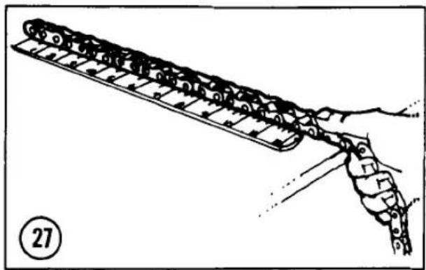
- Lay a scale along the top chain run and measure the length of any 20 links in the chain, from the center of the first pin you select to the 21st pin (Figure 27). If the 20 link length is more than 12.7 in (323 mm), install a new drive chain; see Swing Arm Removal in Chapter Ten.
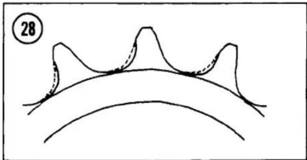
- If the drive chain is worn, inspect the rear wheel and engine sprockets for undercutting or sharp teeth (Figure 28). If wear is evident, replace the sprockets too or you'll soon wear out your new drive chain.
SWING ARM
The swing arm bearings must be lubricated with grease according to the maintenance schedule (Table 1). On 1979-1980 models, there is a grease fitting on the swing arm crossmember. Later models require removal of the swing arm to lubricate the bearings; see Swing Arm Removal in Chapter Ten.
- Use a grease gun to force grease into the fitting on the swing arm, until the grease runs out both ends of the swing arm. If grease doesn't come out of the swing arm ends, loosen the swing arm nut a little and try again, then retorque the nut to 60 ft.-lb. (8.0 mkg).
-
If grease will not run out of the ends of the swing arm, unscrew the grease fitting from the swing arm. Clean the fitting and make certain that its ball check valve is free. Reinstall the fitting.
-
Apply the grease gun again. If grease does not run out both ends of the swing arm, remove the swing arm, clean out the old grease, lubricate the bearings and install the swing arm; see Swing Arm Removal in Chapter Ten.



STEERING
Steering Play Inspection
- Prop up the motorcycle so that the front tire clears the ground.
- Center the front wheel. Push lightly against the left handlebar grip to start the wheel turning to the right, then let go. The wheel should continue turning under its own momentum until the forks hit their stop. Try the same in the other direction.
NOTE
On some bikes, the wiring and control cables tend to stop the wheel movement.
If the steering drags, make sure it's not because of wiring stiffness.
- If, with a light push in either direction, the front wheel will not turn all the way to the stop, the steering adjustment is too tight.
- Center the front wheel and kneel in front of it. Grasp the bottoms of the fork legs (Figure 29). Try to pull the forks toward you and then try to push them toward the engine. If you feel play, the steering adjustment is too loose.
- If the steering is too tight or too loose, adjust it as described under Steering Adjustment in Chapter Ten.
Steering Head Lubrication
The steering head should be disassembled and the bearings cleaned, inspected for wear and lubricated with a waterproof grease according to the maintenance schedule (Table 1); see Steering Adjustment in Chapter Ten.

FRONT FORKS
Air Pressure
Air pressurized forks are standard equipment on some models. Both the fork springs and air pressure support the motorcycle and rider. The air pressure can be varied to suit the load and your ride preference, but it is very important to have the same pressure in both forks to prevent an unbalanced suspension with poor handling. The maximum allowable air pressure difference between the forks is 1.5 psi, so be very careful when adding or bleeding air from the forks. The best way to guarantee equal fork air pressure is to install an accessory pressure equalization line between the forks (Figure 30).
Don't use a high-pressure hose or air bottle to pressurize the forks; a tire pump is a lot closer to the scale you need. S&W offers a combination hand pump/pressure gauge that is ideal (Figure 31).
Keep the following points in mind when adjusting the front forks.
a. Increase air pressure for high-speed riding.
b. If the suspension is too hard, reduce air pressure.
c. If the suspension is too soft, increase air pressure.
d. Occasional bottoming of the forks shows that you are taking good advantage of all their travel. Severe or frequent bottoming should be avoided by increasing air pressure.
- Support the bike with the front wheel off the ground.
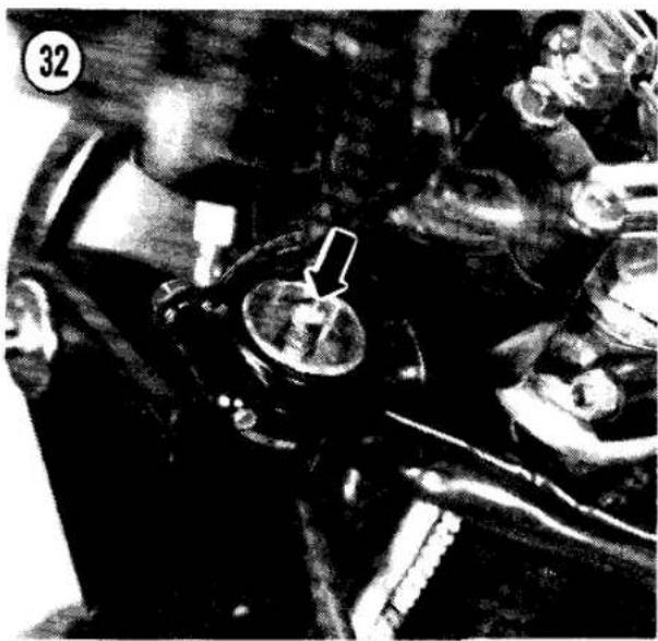
- Remove the air valve caps (Figure 32).
- Connect a pump to the valve and pump the forks up to about 25 psi.
CAUTION
Do not exceed 36 psi, or the fork seals will be damaged.
- Slowly bleed off the pressure to reach the desired value. Refer to Table 4 for standard air pressure and recommended range. Kawasaki recommends balancing light fork air pressure with light rear shock preload and damping and heavy fork air pressure with heavy rear shock preload and damping.
NOTE Each application of a pressure gauge bleeds off some air pressure merely in the process of applying and removing the gauge.
- Install the valve caps and rubber covers.
Inspection
Apply the front brake and pump the forks up and down hard. You should hear the fork oil as it flows through its passages and there should be no binding. Inspect for fork oil leakage around the fork seals. If there is evidence of leakage, check the fork oil level; see Oil Change.
Oil Change
This procedure tells how to change the fork oil without removing the forks from the motorcycle. If the forks are removed and disassembled as described in Chapter Seven, more of the old oil will be drained.
- On models with air pressurized forks, release any air pressure from the fork leg by removing the rubber cap from the top of the fork and pushing in the valve core until all pressure is released.
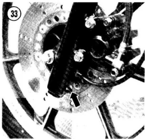
- Place a drain pan under the fork and remove the drain bolt (Figure 33). Let the oil drain for a few minutes, then pump the fork (keeping your hand on the brake lever) to help expel the oil. Install the drain screw and repeat for the other fork leg.
WARNING
Do not allow the fork oil to contact the brake disc or pads. Stopping power would be greatly reduced. If the brakes are contaminated, clean the disc with a non-oily solvent and install new brake pads.
- Support the bike under the engine so the front wheel clears the ground.
- Remove the top plug by pushing the plug in and pry out the circlip (Figure 34).


WARNING
Release all fork air pressure before removing the fork plugs. Air pressure and spring preload may eject the plugs forcibly.
NOTE
You may have to remove the handlebars to get at the fork plugs.

-
Remove the fork spring.
-
Fill the fork tubes with slightly less than the specified quantity of oil; see Table 5 at the end of the chapter.
NOTE
The amount of oil poured in is not as accurate a measurement as the actual level of the oil. You may have to add more oil later in this procedure.
- After filling both tubes, slowly pump the forks up and down by hand several times to distribute the oil throughout the fork damper.
- Measure the distance from top of the fork tube to the surface of the oil (Figure 35).
- Add oil, if required, to bring the level up to specification; see Table 4. Don't overfill the fork legs.
CAUTION
An excessive amount of oil can cause a hydraulic locking of the forks during compression, destroying the oil seals.
- Install the fork spring.
NOTE
If one end of the fork spring has more closely wound coils than the other end, install the spring with the closely wound coils at the top.
- Install the top plug (Figure 36); check that the O-ring is in good condition, push the plug into the fork tube and hold it in place while you install the circlip. Make sure the circlip is fully seated.
- Models with air pressurized forks: Pressurize air forks; see Air Pressure in this chapter.
REAR SHOCK ABSORBERS
Adjustment
The rear shock absorbers feature adjustable spring preload and some models have adjustable damping. Damping adjustment affects mainly extension (rebound) damping.
To adjust spring preload, use the spanner or screwdriver in your motorcycle tool kit to turn both preload adjusters to one of the 5 settings (Figure 37). You will feel the adjuster become harder to turn as you set it for heavy preload.
To adjust damping on early models, turn both damper wheels to one of the 4 click stops marked on the wheel (Figure 38). On later models, turn the chrome shock cover to adjust the damping (Figure 39). Position No. 1 is the lightest damping; position No. 4 is the heaviest damping.
Kawasaki recommends balancing light rear shock preload and damping with light fork air pressure and heavy shock preload and damping with heavy fork air pressure. Increase preload and damping for high speed riding.
WARNING
Both rear shock absorbers must be set at the same preload settings for safe handling. Models with adjustable damping must have both shocks adjusted for the same damping.
Inspection
Check that both rear shock absorber preload adjusters are set at the same notch. On models with adjustable damping, check that both rear shock absorber damping adjusters are set the same. Force the rear of the bike up and down. You should hear the fluid working in the shocks. Check for fluid leakage. If there is fluid leakage replace the shocks; they are not rebuildable. Check the shock mounting bolts for tightness and their rubber bushings for wear (Figure 40).
TIRES
Pressure
Tire pressure must be checked with the tires cold. Correct tire pressure depends a lot on the load you are carrying and how fast you are

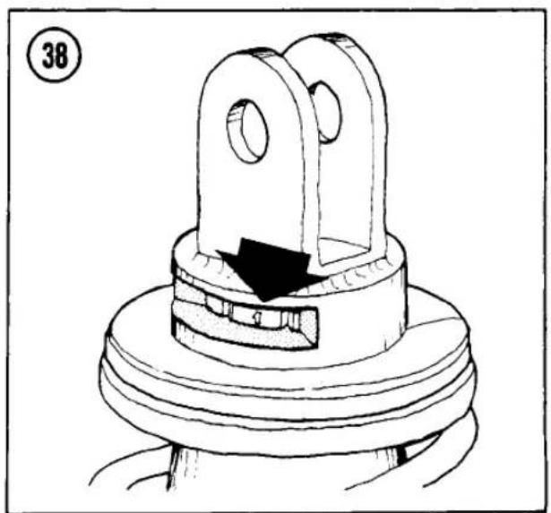

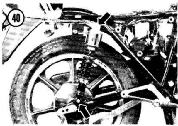


going. A simple, accurate gauge (Figure 41) can be purchased for a few dollars and should be carried in your motorcycle tool kit. See Table 6 at the end of the chapter for tire inflation specifications, or see the tire and load data label on the motorcycle (Figure 42).
Tire Wear
Check the tread for excessive wear, deep cuts and imbedded objects such as stones, nails or glass. If you find a nail in a tire, mark its location with a light crayon before pulling it out. See Tire Changing in Chapter Nine. Check local traffic regulations concerning minimum tread depth. Measure with a small ruler (Figure 43). Kawasaki recommends replacement when the front tread depth is 0.04 in. (1 mm) or less. For the rear tire, the recommended limits are 0.08 in. (2 mm) for speeds below 70 mph and 0.12 in. (3 mm) for higher speeds.
WHEEL BEARING LUBRICATION
The ball bearings in the wheel hubs and the speedometer gear housing at the front wheel should be lubricated with high-temperature grease according to the maintenance schedule (Table 1). Refer to Chapter Nine.
DISC BRAKE
Inspect the brake function, brake fluid level and brake pad wear according to the maintenance schedule (Table 1). The front disc brake automatically compensates for wear and requires no periodic free play adjustment. On models with a rear disc brake, the brake pedal free play must be adjusted any time the pedal height is changed.
Brake Function
Check for a solid feel at the lever and pedal. If the hydraulic brake feels spongy, perform Brake Fluid Bleeding as described in Chapter Nine.
Pedal Height
The rear brake pedal height can be adjusted for comfort and for quick reaction time. Once you have set the pedal height, no periodic

adjustment will be required, but the adjustment does affect pedal free play. Normal brake pedal height is about 1 in. (20-30 mm) below the top of the footpeg.
To adjust the pedal height, loosen the locknut (Figure 44) and turn the adjuster bolt as desired, then tighten the locknut. Be sure to adjust pedal free play after adjusting pedal height.
Pedal Free Play
The brake pedal must have about 3/8 in. (8-10 mm) of free play at the pedal or the rear brake may drag and overheat. Inspect pedal free play whenever you change the brake pedal height, or whenever the rear brake drags. Brake pedal free play is the distance the pedal travels before the master cylinder pushrod contacts the piston inside the rear master cylinder. When the brake pedal has any free play, you will be able to jiggle the pushrod freely from side to side. When there is no free play, you won't be able to detect any movement when you push the pushrod from side to side.
To adjust free play, loosen the locknut on the pushrod (Figure 44), then turn the pushrod until the correct free play is achieved. Tighten the locknut.
After adjusting pedal free play, spin the rear wheel to make sure it is turning freely and apply the brake several times to make sure it releases fully.
Brake Light Switch Adjustment
- Turn the ignition switch ON.
- Step on the brake pedal. The light should come on just as the brake begins to work.
- To make the light come on earlier, hold the switch body and turn the adjusting nut (Figure 45), or locknuts, to move the switch body up. Move the switch body down to delay the light.
NOTE
Some riders prefer having the light come on a little early. This way, they can tap the pedal without braking to warn drivers who follow too closely.
CAUTION
Do not turn the brake light switch body or you may twist the wires off.
Fluid Level Inspection
On models with translucent reservoirs or transparent windows, check that the fluid level is between the upper and lower level lines (Figure 46 or Figure 47) or above the lower line (Figure 48). If you can not see the fluid level, remove the reservoir cap.
NOTE
To minimize fluid spillage, hold the handlebar as close to horizontal as possible when removing the front reservoir cap.
Adding Brake Fluid
- Clean the outside of the reservoir cap thoroughly with a dry rag and remove the cap. Remove the diaphragm under the cap.
- Add fresh brake fluid up to the upper level line in the reservoir.


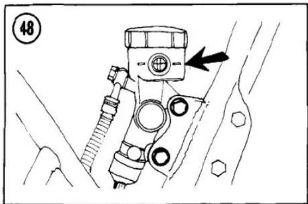
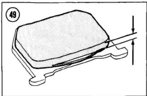
WARNING
Kawasaki recommends DOT 3 brake fluid. Lower grades may vaporize and cause brake failure. Never use old brake fluid or fluid from a container that has been left unsealed for a long time. Do not leave the reservoir cap off too long or the fluid will absorb moisture from the air and will vaporize more easily.
WARNING
Brake fluid is an irritant. Keep it away from your skin and eyes.
CAUTION
Be careful not to spill brake fluid on painted or plastic surfaces or it will destroy the finish. Wash spills immediately with soapy water and rinse thoroughly.
- Reinstall the diaphragm (and washer on the rear master cylinder) and cap. Make sure that the cap is tight.
Pad Wear Inspection
Inspect the disc brake pads for wear according to the maintenance schedule (Table 1).
- Apply the front/rear brake and hold it tight.
- Shine a light between the caliper and the disc to inspect the brake pads.
- If either pad has worn thinner than 1/16 inch (1 mm) or to the stepped portion of the pad (Figure 49 or Figure 50), replace both pads as a set; see Brake Pad Removal in Chapter Nine.
Brake Seal Replacement
The rubber cup inside the master cylinder and the rubber piston seal inside the wheel caliper, and their dust seals, should be replaced every 2 years regardless of the mileage on the bike. Replacement of the seals should be accompanied by inspection and rebuilding of the master cylinder and calipers if necessary. Because of the special tools required for this kind of work, we recommend you have the job done by a Kawasaki dealer. Brake system repair is critical work; see Brakes in Chapter Eight before attempting to rebuild the cylinder and calipers.
Brake Hose Replacement
The hydraulic brake hoses should be replaced every 4 years regardless of the mileage on the bike: see Brake Hose Replacement in Chapter Eight.
DRUM BRAKE
Some models have a drum brake at the rear wheel. Inspect the brake function and brake lining wear according to the maintenance schedule (Table 1).
Pedal Height
Brake pedal height adjustment should not be required once you have set it to the desired position, but it does affect pedal play. Normal brake pedal height is about 1 in. (20-30 mm) below the top of the footpeg.
- Loosen the locknut and turn the adjustment bolt to get the correct pedal height (Figure 51).
- Tighten the locknut.
- Adjust brake pedal play.
Pedal Play
Turn the adjustment nut on the end of the brake rod (Figure 52) until the brake pedal has about 1 in. (20-30 mm) travel from the rest position to the applied position when the pedal is depressed lightly by hand.
After adjusting pedal play, spin the rear wheel to make sure it is turning freely and apply the brake several times to make sure it releases fully.
Adjust the rear brake light switch as described in the section under Disc Brakes.
Brake Light Switch Adjustment
- Turn the ignition switch ON.
- Step on the brake pedal. The light should come on just as the brake begins to work.
- To make the light come on earlier, hold the switch body and turn the adjusting nut (Figure 45), or locknuts, to move the switch body up. Move the switch body down to delay the light.
NOTE
Some riders prefer having the light come on a little early. This way, they can tap the pedal without braking to warn drivers who follow too closely.

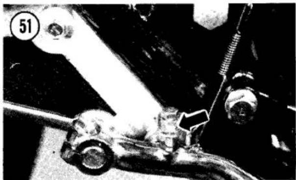
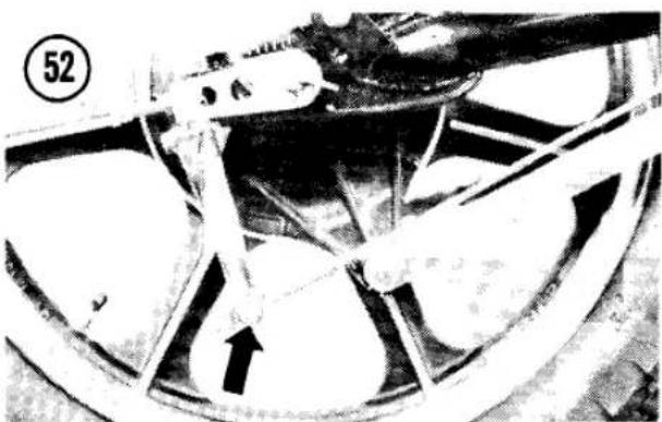
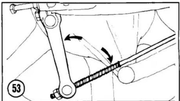

CAUTION Do not turn the brake light switch body or you may twist the wires off.
Lining Wear Inspection
Inspect the brake linings for wear according to the maintenance schedule (Table 1).
-
Apply the brake fully and hold it there.
-
The brake cam arm should form an angle of 80-90° with the brake rod when the brake is applied (Figure 53). If the angle exceeds 100°, remove the brake arm bolt and arm and reposition the arm on the splined camshaft so that you get an 80-90° angle when the brake is applied. Do not remove or reposition the wear indicator pointer.
-
Check the brake lining wear indicator on the backing plate (Figure 54). When the wear indicator pointer moves out of the "USABLE RANGE" mark with the brake applied, disassemble the brake and inspect the linings. See Drum Brake Inspection in Chapter Nine.
Brake Lubrication (Drum Brake)
The brake cam and pivot inside the brake drum should be lubricated according to the maintenance schedule (Table 1). Refer to Chapter Nine. Drum Brake Assembly.
NUTS, BOLTS AND FASTENERS
Check all exposed nuts, bolts, cotter pins, safety clips and circlips. Pay particular attention to:
a. Control lever, pedal and linkage pivots
b. Engine mounting bolts
c. Handlebar clamp bolts
d. Top fork clamp bolts
e. Bottom fork clamp bolts
f. Front axle clamp and axle nuts
g. Shock absorber mounts
h. Swing arm pivot
i. Rear brake torque link
j. Rear axle nut
This check is especially important on high-mileage machines.
ENGINE TUNE-UP
The following list summarizes routine engine tune-up procedures. Detailed instructions follow the list. These tune-up procedures are arranged so that you start with the jobs that require a "cold" engine and finish with the jobs that call for a fully warmed-up engine. If you follow the sequence, you won't waste time waiting for your bike to cool down when required. If you aren't giving the bike a complete tune-up, backtrack through the procedures to make sure you've installed all parts. Consult Chapter Two for troubleshooting procedures when you suspect more serious trouble. Refer to Table 3 at the end of the chapter for tune-up specifications.
- Inspect the air filter and clean it or install a new one.
- Clean the fuel system. Inspect the fuel lines for cracks or leakage.
- Inspect the spark plugs. Clean them and adjust the gap or replace them if necessary. Leave the plugs out until after you inspect valve clearance.
- Inspect valve clearance and adjust if necessary.
5A. On models with contact beaker point ignition: Inspect the contact breaker points. Adjust the gap or replace the points if necessary. Lubricate the point cam wick very lightly.
5B. On models with transistorized ignition: Ignition timing inspection is optional.
6. Adjust the carburetors if required (throttle cable play, idle mixture on all except U.S. models and idle speed).
7. Check and record cylinder compression.
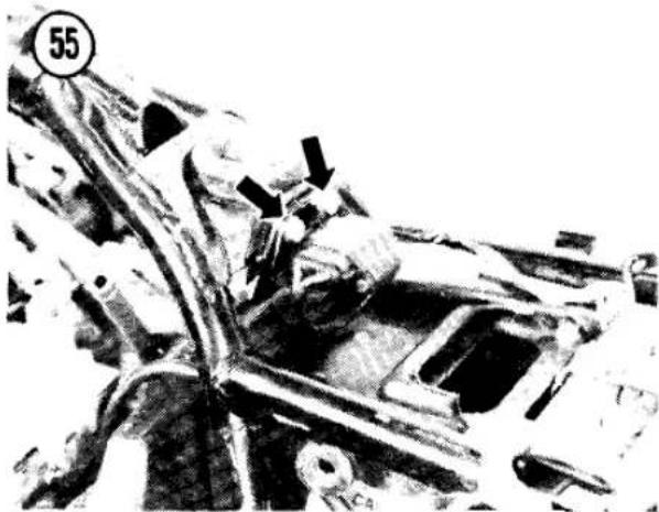


AIR FILTER
A clogged air filter will cause a rich fuel/air mixture, resulting in power loss and poor gas mileage. Never run the bike without an air filter. Even minute particles of dust can cause severe internal engine wear and clogging of carburetor passages.
NOTE The air filter element is a dry paper type. Do not oil the filter or you will ruin it and cause the engine to run too rich.
Removal/Installation
-
KZ500 and KZ550-D: Remove the fuel tank; see Fuel Tank Removal in Chapter Seven. Remove the baffle plate mounting bolts and washers (Figure 55) and move the plate aside for filter clearance.
-
Remove the 2 air cleaner cover screws and washers (Figure 56).
-
Lift the rear of the fuel tank for clearance if necessary and remove the filter (Figure 57).
- To install, reverse the removal steps. Make sure the bottom of the filter is squarely seated in front of the ridge in the bottom of the still air box (Figure 58). Make sure the filter element doesn't crimp or slip off its frame when you install it.
Cleaning
Tap the filter sharply against a solid surface to remove the heavy particles, then blow it clean with compressed air, if available. Kawasaki recommends cleaning the paper-type filter in a non-oily solvent, then allowing it to dry.
Install a new air filter every 5 cleanings or every 6,000 miles (10,000 km) or any time the element or gaskets are damaged. Clean the filter more frequently in dusty areas and after riding in the rain.

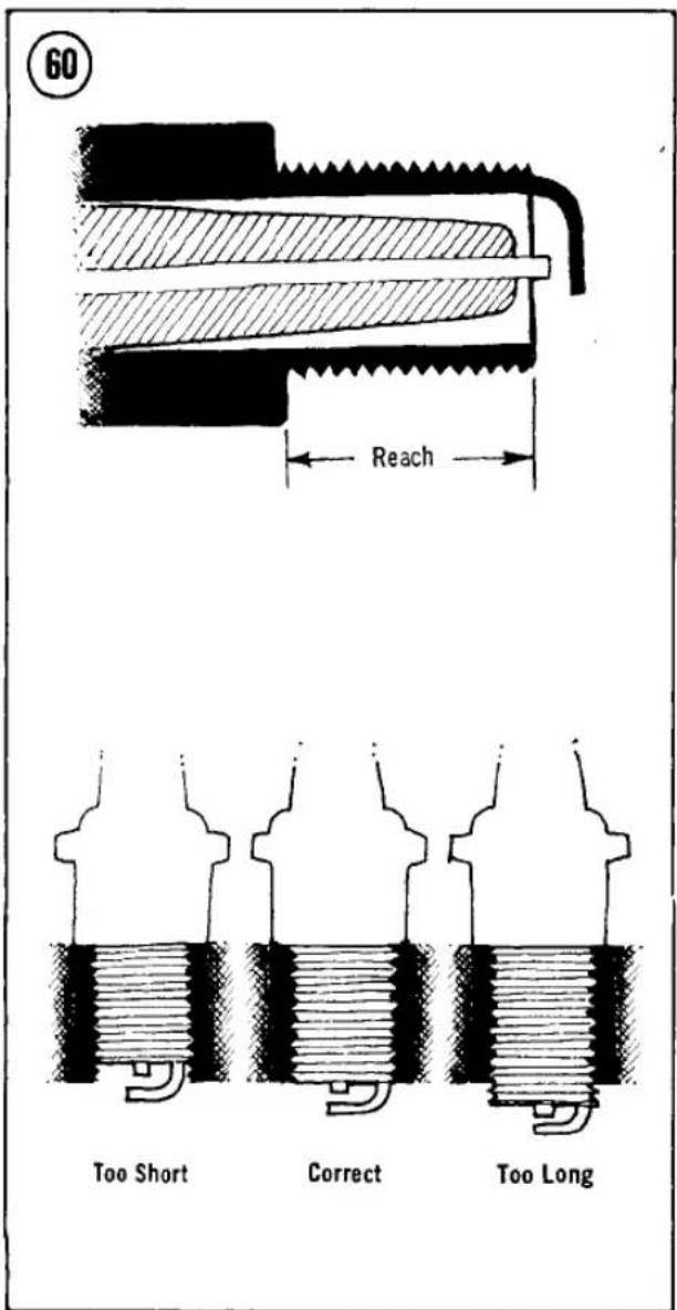
FUEL SYSTEM
As water and dirt accumulate in the fuel tank or carburetor float bowls, engine performance will deteriorate. The fuel system should be cleaned when the engine is cold so gasoline doesn't spill on hot surfaces.
WARNING Some fuel may spill during these procedures. Work in a well-ventilated area at least 50 feet from any sparks or flames, including gas appliance pilot lights. Do not smoke in the area.

Fuel System Cleaning
- Check that the ignition switch is OFF.
- Turn the fuel tap to PRI (prime).
- Check to see how the carburetor overflow tubes are routed (A, Figure 59). then pull them up and put their ends into a container suitable for gasoline.
- Loosen one float bowl drain screw 1 or 2 turns (B. Figure 59). Any accumulated water will flow out of the attached overflow hose. When clean gasoline comes out of the tube, tighten the drain screw. Repeat for the other carburetors, then reposition the overflow tubes.
- If any dirt came out of the carburetors, inspect and clean the carburetors, fuel tap and fuel tank as described in Chapter Seven.
- Make sure there are no leaks and that the fuel lines are not cracked or worn out.
Fuel Line Replacement
The rubber fuel lines should be replaced every 4 years, regardless of the mileage on the bike; refer to Chapter Seven.
SPARK PLUGS
Heat Range and Reach
The proper spark plug is very important for maximum performance and reliability. The proper heat range requires that a plug operates hot enough to burn off unwanted deposits, but not hot enough to burn up or cause preignition. A spark plug of the correct heat range will show a light tan color on the portion of the insulator
within the cylinder after the plug has been in use.
The spark plug recommended by the factory is usually the most suitable for your machine. For low speed riding, or when riding in cold weather, a plug one step hotter may be preferable. Refer to Table 3 at the end of the chapter for the recommended spark plug.
CAUTION
Ensure the spark plug used has the correct thread reach (Figure 60). A thread reach too short will cause the exposed threads in the cylinder head to accumulate carbon, resulting in stripped cylinder head threads when the proper plug is installed. Too long a reach may cause plug/piston contact and serious damage.
Removal/Inspection/Installation
- Grasp the spark plug lead as near to the plug as possible and pull it off the plug. Clear away any dirt that has accumulated in the spark plug well.
CAUTION
Dirt could fall into the cylinders when the plug is removed, causing serious engine damage.
-
Remove the spark plug with a spark plug wrench.
-
Inspect the spark plug carefully. Look for broken center porcelain, excessively eroded electrodes and excessive carbon or oil fouling (refer to Figure 3 in Chapter Two as a plug "reading" aid). If deposits are light the plug may be cleaned with a wire brush or in a spark plug sandblast cleaner, but the price of new plugs is cheap insurance for high power and gas mileage. Check the spark plug gasket. If it's completely flattened, install a new one.
CAUTION
Never sandblast an oily or wet plug. The grit will stick to the plug and later drop into the engine. After sandblasting a plug, clean it thoroughly.
- If the plug is reusable, file the center and side electrodes flat. Less voltage is required to jump the gap when the electrode corners are sharp.

-
Measure the gap with a round wire spark plug gauge (Figure 61). The gauge should just be able to pass through the gap. Adjust the gap by bending the side electrode only. The gap should be 0.024-0.028 in. (0.6-0.7 mm).
-
Apply a small amount of anti-sieze compound to the plug threads. Don't use oil or grease—they'll turn to pure carbon and make the plug harder to get out the next time.
NOTE
If you're going to adjust the valve clearance, leave the spark plugs out until you're finished. It will be easier to turn the engine over precisely.
- Clean the seating area on the cylinder head and thread the plug in by hand until it seats. Then tighten the plug 1/8 to 1/2 turn with a spark plug wrench. If you use a torque wrench, the proper torque is 10 ft.-lb. (1.4 mkg).
AIR SUCTION VALVES (U.S. MODELS)
Valve Operation
Models imported in the U.S. are equipped with a simple air suction system to minimize exhaust emissions. The air suction valves (reed valves) allow clean intake air to be sucked into the exhaust ports during exhaust vacuum pulses. This helps to complete combustion of unburned hydrocarbons in the exhaust system.
The air suction valves also prevent exhaust gas from backing up and flowing into the air cleaner. If that should happen, you would have an unplanned and unwanted EGR (exhaust gas


recirculation) system. That would cut power a great deal and probably damage the engine. Periodic inspection of suction valve operation is very important.
Inspection
Check the suction valves with the engine off. You can check the air suction valve function by simply disconnecting the long suction hose at the air cleaner housing (Figure 62). You should be able to blow through this hose into the exhaust system and you should not be able to draw any air out of it because of the suction valve reeds. If you can draw air out of the hose, one or more of the suction valves is faulty.
To remove and inspect each suction valve individually, see Air Suction System in Chapter Seven.
VALVE CLEARANCE
Normal wear of the valves and valve seats decreases valve clearance and alters valve timing slightly. Insufficient valve clearance can lead to burnt valves and seats and will eventually cause serious engine damage. Excessive clearance causes noisy operation and more rapid valve train wear.
Engines that use overhead camshafts with shims to adjust valve clearance should not require frequent valve clearance adjustment, but the clearance must be inspected according to the maintenance schedule (Table 1). Inspection is a simple, easy task compared to adjustment.
NOTE
Check and adjust valve clearance with the engine cool, at room temperature.
Inspection
WARNING
Some fuel may spill during these procedures. Work in a well-ventilated area at least 50 feet from any sparks or flames, including gas appliance pilot lights. Do not smoke in the area. Keep a BC rated fire extinguisher handy.
- Check that the ignition switch is OFF.
- Remove the fuel tank; see Fuel Tank Removal in Chapter Seven.
- Remove the valve cover; see Valve Cover Removal in Chapter Four.
- Check that all 16 camshaft cap bolts (Figure 63) are properly tightened to 8.5 ft.-lb. (1.2 mkg).
- Remove the timing cover and gasket from the lower right side of the engine (Figure 64).
- Turn the crankshaft clockwise with a 17 mm wrench on the outer advancer bolt (Figure 65) until one of the cam lobes is pointing directly away from its valve (Figure 66).
CAUTION
Do not use the small inner bolt to turn the engine or you will damage the ignition advance mechanism.

- Insert a feeler gauge between the cam lobe and the lifter (Figure 67). The clearance is measured correctly when the feeler gauge drags slightly when it is inserted and withdrawn. Repeat for all valves, turning the crankshaft clockwise. Record the measurements and cylinder numbers.
NOTE
The cylinders are numbered 1 through 4, starting at the left side of the engine. Intake valves are at the rear of the engine; exhaust valves are at the front.
- If any valve's clearance is not within the range specified in Table 3, skip ahead to Valve Clearance Adjustment. If all the valve clearances are within specification, continue
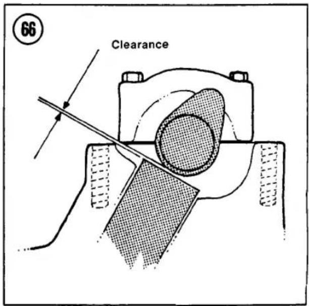



this procedure and install the removed parts.
-
Install the valve cover; see Valve Cover Installation in Chapter Four.
-
Install the fuel tank; see Fuel Tank Installation in Chapter Seven.
Adjustment
To adjust the valve clearance, the camshaft must be removed and the shim under the valve lifter must be removed and replaced with one of a different thickness. The shims are available from Kawasaki dealers in increments of 0.05 mm and range in size from 2.0-3.2 mm (shim No. 200 to shim No. 320). The dimension is often marked on the bottom shim surface.
This procedure pertains only to valves that need adjustment. Do not remove any shims on valves whose clearance falls within the specified range.
- Remove the camshaft with valve clearances to be adjusted; see Camshaft Removal in Chapter Four.
- Remove the lifter (A. Figure 68).
CAUTION
Be very careful not to damage the outer surface of the lifter. Use a rubber suction cup, if available, to pull the lifter out.
- Remove the shim (B, Figure 68). Check the thickness marked on it or measure the shim thickness with a micrometer.
- Calculate the correct shim thickness using this example. Refer to Table 3 for the specified clearance.
NOTE
The following numbers are for example only.
Example:
Actual measured clearance .... 0.52 mm Subtract specified clearance .... -0.15 mm Equals excess clearance .... 0.37 mm
Existing shim number .... 220 Add excess clearance .... +37 Equals new shim number .... 257 (round up to the nearest shim number) .... 260
- Insert the new shim under the valve lifter.
CAUTION
Never put shim stock under a shim. The shim could come loose at high rpm and cause extensive engine damage. Never grind the shim; this can remove the hardened outer shim surface and cause a fracture and extensive engine damage.
NOTE
If the smallest available shim does not increase clearance to within acceptable limits, the valve seat is probably worn. If this is the case, repair the valve seat, grind the valve stem slightly and recheck the clearance. See Valve/Seat Inspection in Chapter Four.
CAUTION
Do not insert the cam chain tensioner cross wedge until after the valve cover and its chain guide are installed and the tensioner assembly is installed on the cylinder block.
- Install the camshaft; see Camshaft Installation in Chapter Four.
- Install the valve cover; see Valve Cover Installation in Chapter Four.
- Install the fuel tank; see Fuel Tank Installation in Chapter Seven.
CONTACT BREAKER POINTS
A contact breaker point ignition is used on early models (Figure 69). During normal operation, the contact surfaces of the points gradually erode and become contaminated. The point rubbing block also wears, retarding ignition timing. Periodic cleaning and gap adjustment is required to keep the engine operating at peak efficiency.
Inspection
- Check that the ignition switch is OFF.
- Remove the spark plugs.
- Remove the ignition timing cover and gasket.
- Inspect the contact point surfaces (Figure 70). If the points are not badly pitted they can be removed and dressed with a few strokes from a point file; Flexstone is a good brand to use. If the contact surfaces are badly pitted,

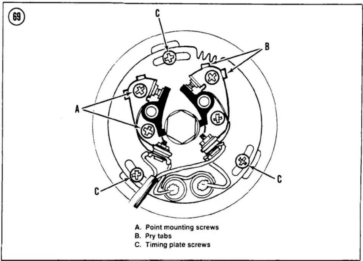
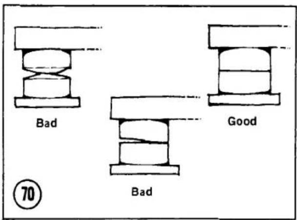

replace the breaker point assembly and the condenser.
NOTE
Don't use sandpaper or emery cloth for dressing the points. They will leave abrasive particles embedded in the points and cause arcing.
- Clean the contact surfaces; close the points on a piece of clean paper, such as a business card, and pull it through the points. Do this
until no discoloration or residue remains on the card. Check the points when closed. If they do not meet squarely (Figure 70), replace them.
- Inspect the breaker spring tension by hand. A weak breaker spring will allow the points to bounce at high engine speeds and cause misfiring. Usually the spring will last for the life of the contacts.
- Apply a small amount of point cam lubricant or high-temperature grease to the felt that bears against the point cam. If you use too
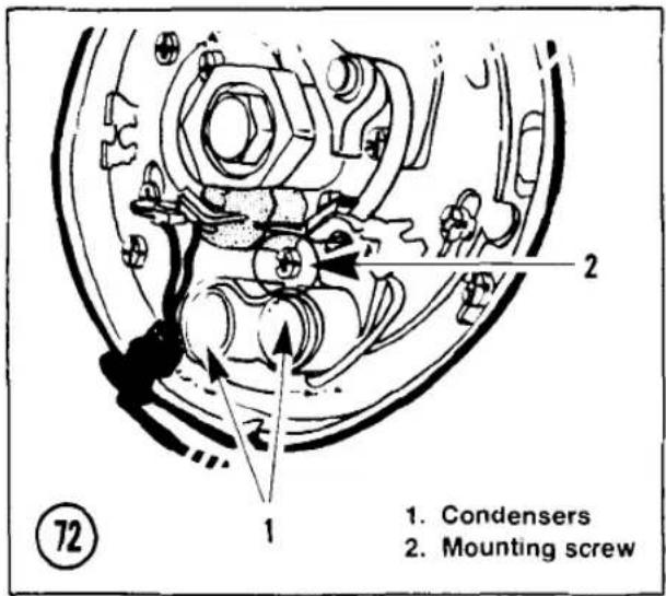
much grease, the cam will sling it onto the contacts, fouling them.
- Inspect point gap and ignition timing.
Gap Measurement (With Feeler Gauge)
- Turn the crankshaft to the right (clockwise), using a 17 mm wrench on the bolt on the end of the crankshaft, until the points are open to their widest gap.
- Measure the point gap with a clean flat feeler gauge. The gap should be 0.014 in. (0.35 mm).
NOTE
There should be a slight drag on the feeler gauge as it is inserted and removed. Hold the gauge loosely in your fingers to make sure you're not prying the points open.
- To adjust the point gap, loosen the 2 point mounting screws slightly (Figure 69), then insert a screwdriver into the pry slots and move the base contact as required to set the gap. Tighten the screws and recheck the gap; it often changes as the screws are tightened.
- Check the gap on the remaining set of points. Adjust it if necessary.
- Inspect the ignition timing.
Gap Measurement (With Dwell Angle Meter)
The dwell angle is the number of degrees (or the percentage of 360° ) of point cam rotation during which the points are closed and current can flow through them to the primary winding of the ignition coil. The breaker point gap can be measured with greater accuracy with a dwell angle meter than with feeler gauges.
- Connect a dwell angle meter according to the manufacturer's instructions.
- Install the spark plugs; see Spark Plugs in this chapter.
- Start the engine and allow it to idle.
- Note the reading on the meter. The reading for the correct gap on a meter calibrated in percentages is 13%; the correct reading for a meter calibrated in degrees is 48° when set for "4 cylinder."
- If the reading is incorrect, adjust the point gap. Loosen the 2 point mounting screws slightly (Figure 69), then insert a screwdriver into the pry slots and move the stationary contact as required to obtain the correct meter reading. Tighten the screws and recheck the meter reading; it often changes as the screws are tightened.
- Check the dwell on the remaining set of points. Adjust if necessary.
- Inspect the ignition timing.
Contact Point and Condenser Replacement
It is a good idea to replace the condenser every time you replace the points, but if you want to use the old condenser, you can test it easily after removal by touching the outer case to the battery negative (-) terminal and connecting the condenser lead to the battery positive (+) terminal. Allow the condenser to charge for a few seconds, then quickly remove it from the battery and touch the condenser lead to its case (Figure 71). If you see a spark as the lead touches the case, you can assume the condenser is okay.
- Check that the ignition switch is OFF.
- Remove the screws that mount each contact point assembly to its backing plate (Figure 69).
- Lift the point assembly from its pivot. Loosen the nut and remove the ignition coil wire from the point terminal.
- Remove all old lubricant from the point cam and apply a sparing coat of fresh point cam lubricant. Do not use too much.
- Remove the screw that mounts the condensers (Figure 72) and remove the condensers.
- Install new condensers and points, making sure the new points are clean and that the backing plate is clean for a good ground connection. The green wire goes to the front set of points and the black wire goes to the rear set of points.
- Adjust the point gap and ignition timing.
IGNITION TIMING (CONTACT POINT IGNITION)
Periodic inspection and adjustment of ignition timing is necessary to compensate for contact point and rubbing block wear. Failure to do so will result in incorrect ignition timing, which in turn may cause poor performance, overheating, knocking or engine damage.
Clean the contact points and adjust their gap before inspecting ignition timing.
There are 2 ways to inspect ignition timing: static (engine not running) and dynamic (engine running). Dynamic timing inspection is preferable if a strobe timing light (Figure 73) is available, because it checks timing under actual operating conditions and allows inspection of the ignition advance function.
Check that the idle speed is within specification before inspecting dynamic timing, because a very high idle speed will begin the ignition advance process and give a faulty reading: see Idle Speed in this chapter.
Dynamic
- Install the spark plugs; see Spark Plugs in this chapter.
- Remove the ignition timing cover and gasket.
- Hook up a stroboscopic timing light to cylinder No. 1 or No. 4, according to the manufacturer's instructions.
- Start the engine and allow it to idle. Shine the light at the timing inspection marks. The "F" mark for cylinders No. 1 and No. 4 should align with the index mark at idle (Figure 74).
NOTE
For clarity, the timing marks are shown with the timing plate assembly removed. Observe the marks through the upper hole in the timing plate.

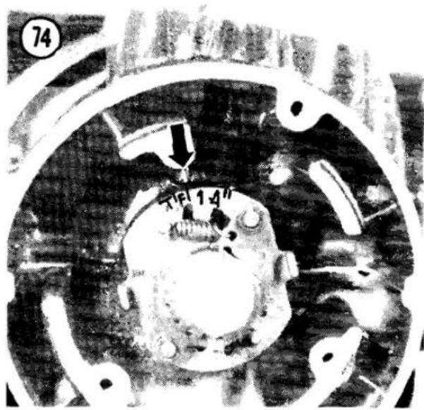
- If the "F" mark does not align at idle, loosen the 3 timing plate screws (Figure 69) and rotate the base plate as required to align the marks. Tighten the timing plate screws and recheck the timing.
- Increase the engine speed to 3,400 rpm and check that the pointer falls between the double line advance mark (Figure 75). If the advancer does not work correctly, refer to Ignition Advance Unit in Chapter Four.
- Connect the stroboscopic timing light to cylinder No. 2 or No. 3. Shine the light at the timing inspection marks. The "F" mark for cylinders No. 2 and No. 3 should align with the index mark at idle. If the "F" mark does not align at idle, loosen the 2 front point mounting screws (Figure 69) and adjust the point gap to


bring this pair of cylinders into time. Tighten the point mounting screws and recheck the timing.
- Stop the engine and install the timing cover and gasket.
Static
-
Turn the ignition switch and kill switch OFF.
-
Connect a timing tester, buzz box or ohmmeter between the rear contact point terminal and the engine case for a good ground.
NOTE
If you don't have a timing tester, you can tell approximately when the points open by inserting a piece of cellophane (a cigarette package wrapper works) between the points and pulling lightly on it while you turn the crankshaft. A simple test light (Figure 76) also will work with the ignition switch and kill switch ON.

- Using the large bolt on the end of the crankshaft, slowly turn the crankshaft to the right (clockwise) until the "F" mark for cylinders No. 1 and No. 4 aligns with the index mark (Figure 74). The timing tester should indicate the breaker points are just beginning to open when the marks align (the tone will change, the bulb will light or the ohmmeter needle will flicker).
- If the ignition timing is incorrect, continue turning the crankshaft until the "F" mark aligns with the index mark again. Loosen the 3 timing plate screws (Figure 69) and rotate the timing plate as required so the points are just beginning to open.
- Tighten the timing plate screws and recheck the timing for cylinders No. 1 and No. 4.
- Connect the timing tester to the front point terminal.
- Using the large bolt on the end of the crankshaft, slowly turn the crankshaft to the right (clockwise) until the "F" mark for cylinders No. 2 and No. 3 aligns with the index mark. The timing tester should indicate the breaker points are just beginning to open when the marks align (the tone will change, the bulb will light or the ohmmeter needle will flicker).
- If the ignition timing is incorrect, continue turning the crankshaft until the "F" mark aligns with the index mark again. Loosen the 2 front point mounting screws (Figure 69) and adjust the point gap to bring this pair of cylinders into time. Tighten the point mounting screws and recheck the timing.
- Install the timing cover and gasket.
IGNITION TIMING (TRANSISTORIZED IGNITION)
Later models are equipped with transistorized ignition (Figure 77). Ignition timing inspection is not required maintenance on models with transistorized ignition. Transistorized ignition initial timing is very stable and once it is set properly it should last the life of the motorcycle without adjustment. This optional procedure is provided in case of suspected trouble.
The ignition advance mechanism is a mechanical device that must be lubricated according to the maintenance schedule (Table 1). If not maintained properly, the advance mechanism could stick and cause low power, overheating, spark knock or detonation. Transistorized ignition can not be checked statically. It must be inspected dynamically (engine running) with a strobe timing light (Figure 73).
Check that the idle speed is within specification before inspecting dynamic timing: see Idle Speed in this chapter. A very high idle speed will begin the ignition advance process and give a faulty reading.
- Install the spark plugs; see Spark Plugs in this chapter.
- Remove the timing cover and gasket from the lower right side of the engine.
- Hook up a stroboscopic timing light to the No. 1 or No. 4 spark plug lead according to the manufacturer's instructions.
- Start the engine and allow it to idle. Shine the light at the timing inspection marks. The "F" mark on the advancer should align with the index mark at idle (Figure 74).
NOTE
For clarity, the timing marks are shown with the timing plate assembly removed. Observe the marks through the upper hole in the timing plate (Figure 77).
- If the "F" mark does not align at idle, stop the engine and remove and inspect the ignition advance assembly; see Ignition Advance in Chapter Eight. Recheck the timing.
- Increase the engine speed to 3,400 rpm and check that the index mark falls between the double line advance mark (Figure 75). If the

advancer does not work correctly, refer to Ignition Advance in Chapter Eight.
- Stop the engine and install the timing cover and gasket.
CARBURETOR
The carburetor should be adjusted only when the engine is fully warmed up and all other tune-up operations done.
Throttle Cable Play
Always check the throttle cables before you make any other carburetor adjustments. Too much free play causes jerky throttle response; too little free play will cause unstable idling.
- Check free play at the throttle grip flange (Figure 78). Kawasaki specifies about 1/8 in. (2-3 mm) free play.
- Push the throttle grip completely closed (past its resting position) and check the clearance between the front cable socket at the carburetor and the throttle pulley (Figure 79). There should be about 1/8 in. (2-3 mm) clearance.
- If adjustment is required, loosen the throttle grip cable adjuster locknuts (A, Figure 78) and shorten the adjusters (B) for maximum free play.
- Lengthen the closing (rear) cable adjuster until you get the specified clearance at the throttle pulley when the throttle is pushed completely closed. Tighten the locknut.
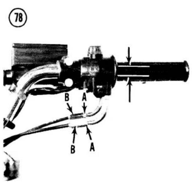



- Lengthen the opening (front) cable adjuster to attain the desired free play. Tighten the locknut.
- If all the adjustment range is used up at the throttle grip, use the adjusters at the carburetor end of the throttle cables (Figure 80).
- Open the throttle fully and check that the open throttle limit screw (Figure 81) contacts its stop. If they do not contact, there is too much throttle cable play and the throttle is not opening fully.
Idle Speed Adjustment
Proper idle speed setting is necessary to prevent stalling and to provide adequate
engine compression braking when you let off the throttle. You can't set it perfectly with the bike's tachometer—it's just not accurate at the low end. You'll need a portable tachometer. If you don't have one, you're about as well off setting idle by ear and feel. If it stalls, set idle faster; if you want more engine braking when decelerating, set idle slower.
- Ride the bike to warm it up fully (about 10 minutes).
- Stop the engine and attach a portable tachometer, following the instrument manufacturer's instructions.
- Start the engine and turn the idle speed screw (A, Figure 82) to set idle as specified in Table 3. If you have no tachometer, set the idle
at the lowest speed at which the engine will idle smoothly.
- Rev the engine a couple of times to see if it settles down to the set speed. Readjust, if necessary.
Idle Mixture Adjustment (Other Than U.S. Models)
The idle fuel/air mixture affects low-speed emissions, as well as idling stability and response off idle; see Idle Mixture Adjustment in Chapter Seven.
On motorcycles imported into the United States, the idle mixture screw is set and sealed at the factory and requires no adjustment.
Synchronization
Synchronizing the carburetors makes sure that one cylinder doesn't try to run faster than the others, cutting power and gas mileage. The only accurate way to synchronize the carburetors is to use a set of vacuum gauges (a manometer) that measures the intake vacuum of all cylinders at the same time. A typical set of gauges is shown in Chapter One.
NOTE
Before you try to synchronize the carburetors, make sure all of the following are checked or adjusted first; if not, you won't get a good synch.
a. Air filter
b. Spark plugs
c. Air suction valves (U.S. models)
d. Valve clearance
e. Point gap and ignition timing
f. Throttle cable play
g. Carburetor holders and clamps air-tight
-
Ride the bike to warm it up fully, set the idle speed, then stop the engine.
-
Remove the rubber caps or vacuum line from the vacuum tap in front of each carburetor (B, Figure 82) and attach a set of vacuum gauges following the instrument manufacturer's instructions.
-
Turn the fuel tap to PRI (prime), start the engine and check that the vacuum difference between the cylinders is less than 0.80 in. Hg (20 mm Hg). Identical readings are desirable.
-
If the difference is greater than specified, remove the fuel tank; see Fuel Tank Removal in Chapter Seven. Hook up a temporary fuel supply or use a long fuel line to connect the carburetors to the fuel tank. Plug the vacuum line that goes from the carburetor to the vacuum fuel tap.
WARNING
When supplying fuel by temporary means, make sure the tank is secure and all fuel lines are tight—no leaks.
- Remove the caps from the carburetors (Figure 83) and loosen the synchronizing screw locknuts (Figure 84).
NOTE
Figure 84 is shown with the carburetors removed for clarity. Do not remove the carburetors for this procedure.
- Start the engine and turn each synchronizing screw until all vacuum readings are within specification. Hold the screws steady while you tighten the locknuts.
- Rev the engine once and check that all cylinders return to equal readings. Readjust if necessary and tighten the adjuster locknuts while holding the adjusters steady.
- Reset the idle speed, stop the engine and install the carburetor caps and vacuum lines or caps.

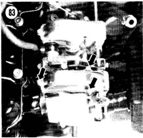


- Install the fuel tank; see Fuel Tank Installation in Chapter Seven.
CYLINDER COMPRESSION
A cylinder cranking compression check is not required maintenance, but it is the quickest way to check the internal condition of the engine: rings, valves, head gasket, etc. It's a good idea to check compression at each tune-up, write it down and compare it with the reading you get at the next tune-up. This will help you spot any developing problems before they cost too much repair money.
- Ride the bike to warm it up fully. Make sure the choke is OFF.
- Remove the spark plugs.
- Insert the tip of a compression gauge into the spark plug hole, making sure it seals fully (Figure 85).
- Turn the kill switch off, hold the throttle wide open and crank the engine several revolutions until the gauge gives its highest reading. Record the number and repeat for the other cylinders.
When interpreting the results, the actual reading is not as important as the difference from the last check and the difference between cylinders. Individual gauge calibrations vary widely. A significant drop (more than 15 psi) since the last check (made with the same gauge) may indicate engine top end problems.
If the compression is 125 psi or more and there is less than a 15 psi difference between cylinders, compression is normal. If either cylinder reads less than about 125 psi, check your readings with a recently calibrated gauge. It may be time to rebuild the top end (rings and valves).
To tell the source of a problem, pour about a teaspoon of motor oil into the spark plug hole. Turn the engine over once to distribute the oil, then take another compression reading. If the compression returns to normal, the valves are good, but the rings are worn. If compression does not increase, the valves may be damaged.
STORAGE
Several months of inactivity can cause problems and a general deterioration of bike

condition if proper care is neglected. This is especially true in areas of weather extremes. During the winter months you should prepare your bike carefully for "hibernation."
Selecting a Storage Area
Most cyclists store their bikes in their home garages. If you do not have a garage, storage spaces are available for rent or lease in many areas. In selecting a building, consider the following points.
- The storage area must be dry, free from excessive dampness. Heating is not necessary, but an insulated building is preferable.
- Buildings with large window areas should be avoided or such windows should be masked if direct sunlight can fall on the bike (also a good security measure).
- If you live near the ocean, make sure the area is sealed against salt spray and mist.
- Select an area with minimum risk of fire or theft. Check your insurance to see if your bike is covered while in storage.
Preparing the Bike for Storage
Careful preparation will minimize deterioration and make it easier to restore the bike to service later. Use the following procedure.
- Ride the bike until it is fully warmed up. Drain the oil, regardless of mileage since the last oil change. Replace the oil filter and fill the engine with the normal quantity of fresh oil.
- Wash the bike completely. Make certain to remove any road salt which may have accumulated during the first weeks of winter. Wax all painted and polished surfaces, including any chromed areas.
- Remove the battery and coat the cable terminals with petroleum jelly. If there is
evidence of acid spillage in the battery box, neutralize with baking soda, wash clean and repaint the damaged area. Store the battery in an area where it will not freeze and recharge it once a month.
- Drain all gasoline from the fuel tank, connecting hoses and carburetors. As an alternative, a fuel preservative may be added to the fuel (the tank should be filled to minimize water condensation). These preservatives are available from many motorcycle shops and marine equipment suppliers.
- Remove the spark plugs and add a small quantity of motor oil to each cylinder. Crank the engine a few revolutions to distribute the oil and install the spark plugs.
- Check the tire pressures. Move the machine to the storage area and prop it up with both wheels off the ground.
- Cover the bike with material that will allow air circulation. Don't use plastic.
Before You Start the Bike
If you prepared the bike for storage, there are only a few things you will need to do before it is ready to ride again.
- Before you move the bike, inflate the tires to the correct pressures. They often get soft over an extended period of non-use.
- Check all fluid levels (brake fluid and engine oil). Top them up if necessary.
- Make sure the battery is fully charged and that the electrolyte level is correct before installing the battery.
- Fill the fuel tank with fresh gasoline (drain and flush the system first if fuel preservative was used).
- Perform a regular tune-up as described in this chapter.
Table 1 KZ500/550 MAINTENANCE SCHEDULE
| Weekly/Gas Stop Maintenance | |
| Tire pressure | Check cold and adjust to suit load and speed |
| Brake function | Check for a solid feel |
| Throttle grip | Check for smooth opening and return |
| Clutch lever play | Check/adjust if necessary |
| Steering | Smooth but not loose |
| Drive chain | Lubricate every 200 miles (300 km) |
| Check/adjust play if necessary | |
| Nuts, bolts, fasteners | Check axles, suspension, controls and linkage/tighten if necessary |
| Engine oil | Check level/add oil if necessary |
| Lights and horn | Check operation, especially brake light |
| Engine noise and leaks | Check for any abnormality |
| Kill switch | Check operation |
| Monthly/3,000 Mile Maintenance (5,000km) | |
| Battery electrolyte level | Check/add water if necessary |
| Check more frequently in hot weather | |
| Brake fluid | Check level/add if necessary |
| 6 Month/3,000 Mile Maintenance (5,000km) | |
| Air filter | Clean or replace |
| Air suction valves | Inspect |
| Fuel system | Drain float bowls |
| Spark plugs | Clean, set gap, replace if necessary |
| Contact breaker points (if so equipped) | Clean, set gap, replace if necessary |
| Ignition timing (breaker point ignition) | Check/adjust if necessary |
| Valve clearance | Check/adjust if necessary |
| Carburetor | Check/adjust cable play, idle speed, mixture if necessary |
| Engine oil and filter | Change oil (and filter every other time) |
| General lubrication | Lube cables, levers, pedals, pivots, throttle grip |
| Clutch | Adjust clutch release |
| Tires | Check wear |
| Drive chain | Check wear |
| Brake pads | Check wear |
| Steering play | Check/adjust if necessary |
| Suspension | Check |
| Yearly/6,000 Mile Maintenance (10,000 km) | |
| Air filter | Change |
| Brake fluid | Change |
| Fork oil | Change |
| Ignition advance | Lubricate |
| Nuts, bolts, fasteners | Check/tighten all |
| Swing arm | Grease pivot |
| (continued) | |

Table 1 MAINTENANCE SCHEDULE (Continued)
| 2 Year/12,000 Mile Maintenance (20,000 km) | |
| Speedometer gear housing | Grease |
| Wheel bearings | Grease |
| Steering bearings | Grease |
| 2 Year Maintenance | |
| Drum brake camshaft | Grease |
| Disc brake master cylinder cup and dust seal | Replace piston seal and dust seal |
| Disc brake caliper | Replace |
| 4 Year Maintenance | |
| Brake hoses | Replace |
| Fuel hoses | Replace |
Table 2 MODEL YEAR/SUFFIX DESIGNATION
| 1979 | 1980 | 1981 |
| KZ500-B1 | KZ500-B2 | KZ500-B3 (European) |
| — | KZ550-A1 | KZ550-A2 (Standard) |
| — | — | KZ550-B2 (European) |
| — | KZ550-C1 | KZ550-C2 (LTD) |
| — | — | KZ550-D1 (GPZ) |
Table 3 TUNE-UP SPECIFICATIONS
| Spark plug gap | 0.024-0.028 in. (0.6-0.7 mm) |
| Spark plug type | NGK-D8EA; ND X24ES-U |
| Valve clearance (cold) | |
| Intake (rear) | 0.004-0.008 in. (0.10-0.20 mm) |
| Exhaust (front) | 0.006-0.010 in. (0.15-0.25 mm) |
| Idle speed | 1,000-1,100 rpm |
Table 4 FORK AIR PRESSURE
| Model | Standard | Range |
| KZ550-C | 8.5 psi (60 kPa) | 7-10 psi (50-70 kPa) |
| All others | 10 psi (70 kPa) | 8.5-11.5 psi (60-80 kPa) |
Table 5 STANDARD FORK OIL*
| Model | Dry CapacityU.S. FI. Oz.(cc) | Wet CapacityU.S. FI. Oz.(cc) | Oil LevelInches (mm) |
| KZ500-B1,B2KZ550-A1 | 7.4 (220) | 6.8 (200) | 19.9 (505) |
| KZ500-B3KZ550-A2,B2, D1 | 8.3 (245) | 7.6 (225) | 20.5 (520) |
| KZ550-C | 9.8 (290) | 9.1 (270) | 14.0 (356) |
| * Fork oil level is checked with forks fully extended and the fork spring removed. Use oil grade SAE 5W20. | |||
Table 6 KZ500/550 TIRES AND TIRE PRESSURE
| Model/Tire Size | Pressure @ Load | |
| 0-215 lb.(0-97.5 kg) | Over 215 lb.(Over 97.5 kg) | |
| KZ500-B1,B2, KZ550-A1 (Tube-type) | ||
| Front—3.25H-19 4PR | 28 psi (200 kPa) | 28 psi (200 kPa) |
| Rear—3.75H-18 4PR | 36 psi (250 kPa) | 40 psi (280 kPa) |
| KZ500-B3, KZ550-A2,B2,D1 (Tubeless) | ||
| Front—3.25H-19 4PR | 28 psi (200 kPa) | 28 psi (200 kPa) |
| Rear—3.75H-18 4PR | 32 psi (225 kPa) | 40 psi (280 kPa) |
| KZ550-C1, C2 (Tubeless) | ||
| Front—3.25S-19 4PR | 25 psi (175 kPa) | 25 psi (175 kPa) |
| Rear—130/90-16 67H 4PR | 21 psi (150 kPa) | 28 psi (200 kPa) |
NOTE: If you own a 1982 or later model, first check the Supplement at the back of the book for any new service information.
CHAPTER FOUR
ENGINE
This chapter provides complete service and overhaul procedures for the Kawasaki 500/550cc 4-cylinder engines. Table 1 provides detailed specifications for the engine. Table 2 provides tightening torques. Table 1 and Table 2 are at the end of the chapter. Routine inspections and adjustments, including a cranking compression test, are given in Chapter Three.
This chapter is written in a general teardown sequence. If you only need to remove one particular part, follow the Removal or Disassembly procedures until you have the part you want. Then refer to the Inspection procedure for that part and finally backtrack through the Assembly or Installation procedures.
Although the clutch and transmission are located within the engine, they are covered in separate chapters to simplify the material.
Service procedures for all models are virtually the same. Where differences occur, they are identified. Right now, before you start any work, go back and read the Service Hints in Chapter One. You will save yourself a lot of mistakes with those hints fresh in your mind.
TOOLS
Several specialized tools will be helpful in the disassembly and inspection procedures in this chapter.
Although you may be able to make do without circlip or snap ring pliers (Figure 1), we highly recommend you have pliers with both straight and angled tips to prevent damage or loss of circlips.
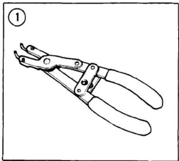

Inspection measurements require a precision inside and outside micrometer, dial gauge or the equivalent (Figure 2 and Figure 3). If you don't have the right tools, remove the parts and have your dealer or machine shop take the required measurements.
ENGINE DESIGN
The unit construction combines the power plant, clutch and transmission into one set of engine cases.
The crankcase is the front portion of the aluminum alloy engine cases, which are split horizontally. The forged one-piece crankshaft is mounted in 5 split insert main bearings. Power is delivered to a secondary shaft by a primary drive chain inside the crankcase. The secondary shaft drives the clutch ring gear and contains the starter clutch mechanism.
The 4 pistons operate inside an alloy cylinder block with pressed-in iron cylinder sleeves. The alloy cylinder head houses the 2 overhead camshafts. Both camshafts are driven by a single chain from a sprocket on the crankshaft (between cylinders 2 and 3). The cam lobes depress lifter cups fitted to the tops of the valve stems, opening the valves.
The alternator is mounted on the left-hand end of the crankshaft. The ignition timing system (contact breaker points or electronic pickups) and advance mechanism are on the right-hand end of the crankshaft.
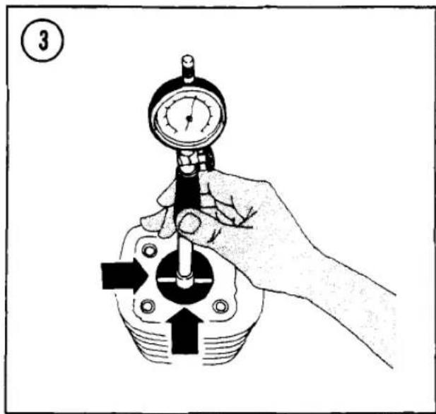

Engine lubrication is by wet sump, with the oil supply stored in the bottom of the crankcase. An oil pump, reached from the bottom of the engine, feeds the main and big-end bearings, primary chain, camshafts and valves, and some of the bearings on the transmission shafts.
The KZ550-D is factory-equipped with an oil cooler.
BREAK-IN
Following cylinder repair (boring, honing, new rings, etc.) and major lower end work, the engine should be broken in just as though it were new. The performance and service life of the engine depend greatly on a careful and sensible break-in. For the first 500 miles, no more than 1/3 throttle should be used and speed should be varied as much as possible within the 1/3 throttle limit. Avoid prolonged, steady running at one speed, no matter how moderate, as well as hard acceleration. Following a 500 mile service, increasingly more throttle can be used, but full throttle should not be used until the motorcycle has covered at least 1,000 miles and then it should be limited to short bursts until 1,500 miles have been logged.
SERVICING ENGINE IN FRAME
The engine has been laid out so that most top end repairs (camshaft, cylinder head, cylinder
block and piston) can be done with the engine still in the frame. However, for repairs to the bottom end (crankshaft, cam chain, connecting rods and bearings), transmission and shift drum/forks, the engine must be removed from the frame for separation of the crankcases.
Although the engine top end can be left attached for engine removal, we recommend that you remove it first. It makes the engine much easier to handle. Also, while the engine is in the frame, you can use the rear brake to lock the drive train, instead of resorting to makeshift or expensive tools. Once the engine is removed from the frame, some parts (like the alternator rotor, secondary shaft nut, and clutch) cannot be loosened without special tools or locking techniques.
CAM CHAIN AND TENSIONER
See Figure 4. Proper cam chain tension is essential for safe operation, quiet running and maximum power. The cam chain is endless and wraps around the crankshaft, so it can't be removed without splitting the crankcases; see Crankshaft Removal in this chapter. The chain

guides are removed during top end disassembly. The tensioner pushrod is held against the rear chain guide by the cam chain tensioner assembly.
CAM CHAIN TENSIONER
See Figure 4. The automatic tensioner is continually self-adjusting. The tensioner pushrod is free to move inward, but can't move out because of the spring-loaded cross wedge assembly.
The cross wedge cap (A, Figure 5) should be removed before performing any work that slackens the cam chain. The cap must be removed before installing the valve cover.


NOTE
Early 1980 KZ550's below engine number 9031 were subject to excessive cam chain noise caused by a cross wedge spring that was too weak. If you have one of the affected bikes and your cam chain is noisy in spite of proper assembly, check the free length of your cross wedge spring. The proper spring is about 1.8 in. (46.2 mm) long. The weak spring is about 2.1 in. (53.2 mm) long. Take the bike to your Kawasaki dealer for correction of this problem.
Removal
- Remove the carburetor assembly (see Carburetor Removal in Chapter Seven). As an alternative, loosen the clamps at the front of the carburetors and slide the carburetor assembly back out of the front rubber holders; push the front of the carburetors up for working room.
- See Figure 4. Remove the cross wedge cap, washer, spring and cross wedge (Figure 6).
- Remove the 2 tensioner mounting bolts (B, Figure 5) and the tensioner assembly.
CAUTION
Do not loosen the tensioner mounting bolts without removing the cross wedge cap. The pushrod would overextend and lock, damaging the cam chain when the mounting bolts are tightened.
Tensioner Disassembly
- Remove the pin (A, Figure 7) that keeps the pushrod from falling out during removal/installation.


- Pull out the pushrod and the heavy spring (B. Figure 7).
Assembly
- Clean the tensioner body and all parts in solvent.
- Grease the pushrod and cross wedge with molybdenum disulfide grease.
- Insert the large spring and pushrod into the tensioner body with the pushrod flat facing the pin on the side of the tensioner.
CAUTION
Do not insert the cam chain tensioner cross wedge until after the valve cover and its cam chain guide are installed and the tensioner body is installed on the cylinder block.
Installation
- Install the tensioner body and O-ring on the cylinder block.
- After engine top end assembly is complete, grease the tensioner cross wedge and push it into the body lightly by hand so the flat on the end of the cross wedge faces the flat on the end of the pushrod. The end of the cross wedge should stick out about 7/16 in. (11-12 mm) from the tensioner body (Figure 8). If the cross wedge sticks out much more or less then specified, recheck for proper engine and tensioner assembly; the cam chain, guides or sprockets may be excessively worn.
- Install the cross wedge spring, check that the aluminum washer is in place and install the cap.
- Install the carburetor assembly; see Carburetor Installation in Chapter Seven. Make sure the carburetors are solidly seated all the way into the front rubber holders. Tighten the clamps securely so the carburetors are air tight.
VALVE COVER
Removal
The valve cover must be removed to inspect and adjust valve clearance.
- Check that the ignition switch is OFF.
- Remove the fuel tank; see Fuel Tank Removal in Chapter Seven.

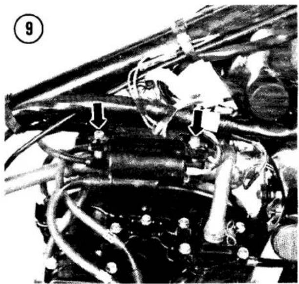
- Disconnect the leads to the ignition coils, then remove the coil mounting nuts and the coils (Figure 9).
- On U.S. models, slide up the lower hose clamps and pull the hoses off the air suction valve covers (A, Figure 10). Swing the vacuum switch and air hoses up out of the way. Remove the bolts securing the air suction valve covers (Figure 10). The covers can stay in place.
- Remove the cam chain tensioner cap and spring; see Cam Chain Tensioner in this chapter. Complete tensioner removal is not necessary.
- Remove the bolts securing the valve cover (Figure 11); there are 20 bolts on U.S. models and 24 bolts on other models. Tap around the cover's edge with a plastic or rubber mallet to loosen it and remove the cover.

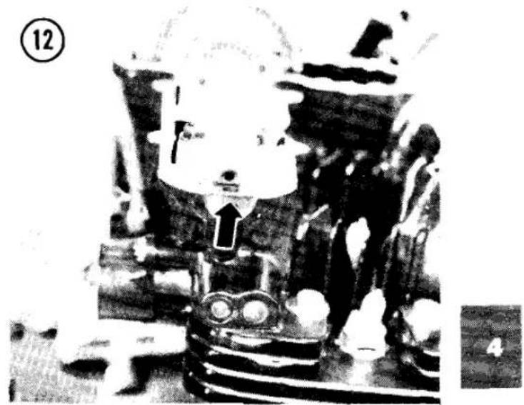


Installation
- Check that the cam chain tensioner cap and spring have been removed; see Cam Chain Tensioner in this chapter.
- Check that the 4 rubber plugs at the ends of the camshafts are in place and in good condition (Figure 12). When installing new plugs, coat the curved sides of the plugs with silicone sealant.
NOTE
If the rubber plugs leak oil, you may be able to stop it by removing and cleaning the plugs, then wrapping them around their circumference with 5 or 6 turns of Teflon tape, such as plumbing pipe thread sealing tape.
- Inspect the top cam chain guide in the valve cover (Figure 13) and replace it if worn deeper than the service limit in Table 1 (Figure 14).
- Place a new valve cover gasket and the valve cover on the cylinder head. The arrow on the cover points to the front (Figure 15).
- Install the valve cover bolts and torque them as specified in Table 2 (Figure 11).
- On U.S. models, install the suction cover bolts and torque them as specified in Table 2 (Figure 10). Install the hoses on the suction covers and slide the hose clamps into place.
- Install the cam chain tensioner cross wedge spring and cap; see Cam Chain Tensioner Installation in this chapter.
- Install the ignition coils and connect the primary coil wires (Figure 9). The yellow/red

wires go to the positive (+) coil terminals (Figure 16). The green wire goes to the left coil and the black wire goes to the right coil.
- Install the fuel tank; see Fuel Tank Installation in Chapter Seven.
- After the engine has run and cooled off, retorque the valve cover bolts to specifications (Table 2).
CAMSHAFT
The exhaust camshaft is at the front of the engine and the intake camshaft is at the rear. The camshaft journals turn in bearing surfaces machined directly into the cylinder head and camshaft caps. There are no separate bearings or bushings. If the bearing surfaces become damaged, the cylinder head and caps must be replaced as a set.
The cam lobes push down on valve lifter cups which lift the valves off their seats. There is a shim under each cup that controls working valve clearance. The shims are available from Kawasaki in a wide range of thicknesses to adjust valve clearance. As the valve and valve seat wear, the working valve clearance changes and the proper clearance must be restored by removing the original shim and installing a thinner or thicker one; see Valve Clearance Inspection in Chapter Three.
Removal
The camshafts can be removed after removing the valve cover.
- Remove the ignition timing cover and gasket from the lower right side of the engine (Figure 17).

16


- Turn the crankshaft (with the 17 mm bolt on the right end of the crankshaft) until the "T" mark next to the No. 1 and No. 4 "F" mark aligns with the fixed pointer (Figure 18). Number 1 and 4 pistons are now at top dead center (TDC).
CAUTION
Do not use the small inner bolt to turn the engine or you will damage the ignition advance mechanism.
-
Remove the 16 bolts securing the camshaft caps (Figure 19). Gently tap the caps with a soft mallet to loosen them and lift them off. There is a hollow dowel pin at each cap.
-
Remove the camshafts. Tie the cam chain up to the frame with wire or place a tool through the chain loop to keep it from falling into the crankcase.
CAUTION
If the crankshaft must be rotated when the cam chain is off the sprockets, pull up on the cam chain and keep it taut while turning the crankshaft. If the chain is slack, it may jam up at the crankshaft and damage the chain and the sprocket.
CAUTION
Do not install the camshafts on a cylinder head that has been removed from the engine. You may bend the valves and the cams must be removed before installing the cylinder head.
Camshaft Inspection
NOTE
Camshaft journal/bearing surface clearance is measured with Plastigage while installing the camshafts. See Camshaft Installation.
-
Check the camshaft journal outside diameters (OD) for wear and scoring (A, Figure 20). If any journal outside diameter is smaller than the wear limit in Table 1, install a new camshaft.
-
Measure the cam lobe height (Figure 21). Replace the camshaft if any lobe height is less than the wear limit in Table 1. The lobes should not be scored and the edges should be
square. Slight damage may be removed with a silicon carbide oilstone. Use No. 100-120 grit initially, then polish with a No. 280-320 grit.
- Inspect the camshaft sprockets for damaged teeth. Install new sprockets if damaged; note the following:
a. The intake and exhaust sprockets are identical; install the sprocket on the camshaft, using the proper holes for each cam (Figure 22).
b. The exhaust camshaft has a tachometer drive gear machined into it (B, Figure 20).
c. The marked side of the sprocket faces the end of the cam with a notch in it (Figure 23).
d. Use a locking agent such as Loctite Lock N' Seal on the sprocket bolts and torque them as specified in Table 2.
Camshaft/Bearing Clearance Inspection
To check camshaft journal/bearing surface clearance with Plastigage, follow the Camshaft Installation procedure, but leave the cam and bearing surfaces dry. It is very important not to turn the cams while assembled dry. After checking clearance, remove and lubricate the cams.
Installation
Whenever a camshaft has been removed, the camshaft rotation must be retimed in relation to crankshaft rotation or the engine will not develop normal power. If the timing is too far off, the valves could try to open when the piston is at TDC (top dead center). Bent or damaged valves and pistons could result.
- Remove the cam chain tensioner cross wedge cap and spring; see Cam Chain Tensioner Removal in this chapter.
- Remove the tachometer bolt and pinion holder stops at the cylinder head (Figure 24). Pull the cable guide and tachometer drive gear from the cylinder head. A gasket and oil seal may come out with it.
- Make sure the No. 1 and No. 4 pistons are still at TDC; the "T" mark next to the No. 1 and No. 4 "F" mark should align with the index mark (Figure 18).
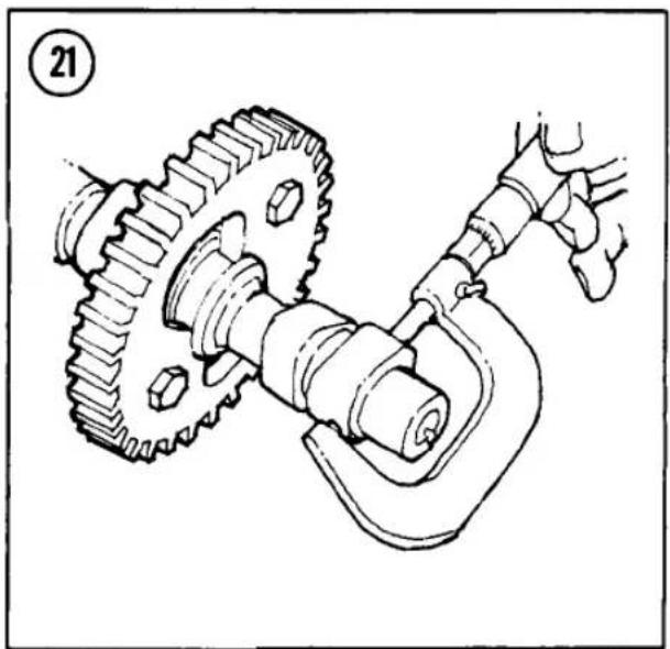
![graph TD A["Exhaust"] --> B["Interior Circle"] B --> C["Intake"] C --> D["Exhaust"] D --> E["Exhaust"] E --> F["Interior Circle"] F --> G["Exhaust"] G --> H["Interior Circle"] H --> I["Exhaust"] I --> J["Interior Circle"] J --> K["Exhaust"] K --> L["Interior Circle"] L --> M["Exhaust"] M --> N["Inte…](/content/2026/06/1280271/images/0d7dc1130d4a2f63211d42fdf66b2ce4fe267a691599a64d5d08cd3dde6b244f.jpg)


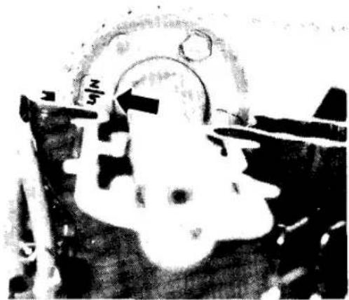
CAUTION
Pull up on the cam chain and keep it taut while turning the crankshaft. If the chain is slack, it may jam up at the crankshaft and damage the chain and the sprocket.
4A. If you are checking cam/bearing clearance with Plastigage, cut strips of Plastigage and lay them lengthwise across each camshaft cap. Do not lubricate the journals or bearing caps until after you remove the Plastigage.
4B. If you are not checking cam/bearing clearance, coat the camshaft journals and lobes with clean engine oil. Use molybdenum disulfide grease if new parts are being installed. 5. Insert the exhaust camshaft through the cam chain into the cylinder head. The exhaust camshaft has a tachometer worm gear machined into it (B, Figure 20). The notched end of the camshaft faces the right side of the engine.
CAUTION
If you did not remove the tachometer drive gear from the cylinder head and if the exhaust camshaft worm drive gear does not mesh with the tachometer drive gear in the cylinder head, the parts will be damaged when the camshaft cap bolts are tightened.
- Without turning the crankshaft, align the "EX" line on the exhaust cam sprocket with the front cylinder head surface (Figure 25). Pull the cam chain tight at the front and fit it onto the sprocket.
NOTE
Do not rotate either camshaft in its bearing surfaces if Plastigage is in place. Instead, lift the camshaft and turn it to align the timing marks.
- Without turning the crankshaft, insert the intake camshaft through the cam chain into the cylinder head. Align the intake sprocket "Z5 IN" line with the rear cylinder head surface (Figure 26) and fit the chain to the sprocket. The notched side of the camshaft faces the right side of the engine.


- Locate the cam chain pin on the exhaust sprocket in line with the "EX" line (Figure 27). Beginning with this pin as zero, count off 43 pins toward the intake cam. The "Z5 IN" line on the intake sprocket must lie between the 43rd and 44th pins. If it does not align, recheck your pin count and reposition the intake camshaft if required.
- Check that the cam chain is properly seated in the front and rear cam chain guides.
- Check that the camshaft cap dowel pins are in place and loosely install the camshaft caps in their original location.
NOTE Each of the caps is numbered to match its location on the cylinder head and marked with an arrow that must point to the front of the engine.
-
Tighten the bolts on each cam's left inside cap just enough to seat the camshafts, then tighten the remaining cap bolts. Torque the cap bolts as specified in Table 2. After you tighten the camshaft cap bolts, the "Z5 IN" mark on the intake sprocket should align with the rear cylinder head surface.
-
If you are checking cam/bearing clearance with Plastigage:
a. Remove the camshaft cap bolts. Remove the caps and measure the width of the

Plastigage with the Plastigage wrapper (Figure 28). The material may stick to the camshaft journal or the cap.
b. If any bearing clearance is larger than the limit in Table 1, install the camshaft caps on the cylinder head without the camshafts and measure the bearing surface inside diameters (ID). If any bearing surface ID is larger than the wear limit in Table 1, install a new cylinder head and all new camshaft caps. The bearing caps and cylinder head are machined as one piece and cannot be replaced separately. If the bearing surface
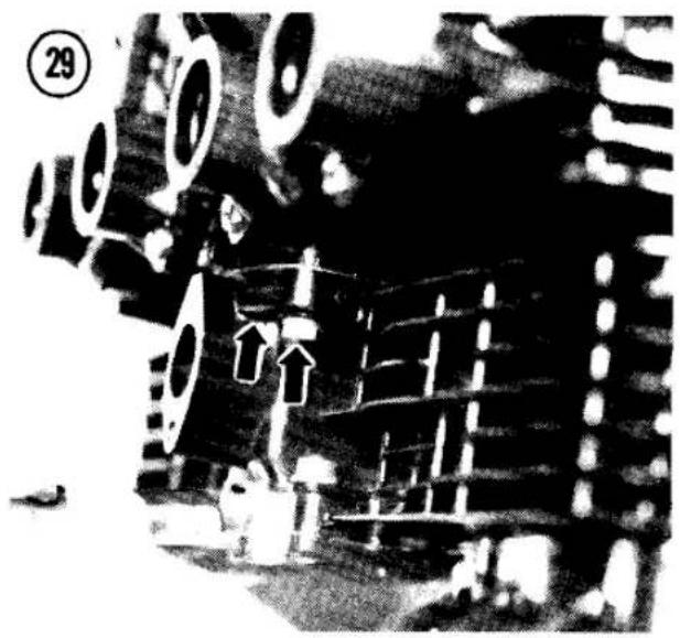
ID does not exceed the limit in Table 1, check clearance with a new camshaft. If a new camshaft will not bring the clearance within specification, the cylinder head must be replaced.
c. Remove the camshafts, clean all Plastigage from the camshafts and caps and reinstall the camshafts beginning at Step 5.
13. Make sure the No. 1 and No. 4 pistons are still at TDC; the "T" mark next to the No. 1 and No. 4 "F" mark should align with the index mark (Figure 18).
14. Slowly turn the crankshaft to the right (clockwise) 2 full turns, using the 17 mm bolt on the right end of the crankshaft. Check that all timing marks again align as shown in Figure 27, except that the "Z5 IN" mark should now align with the rear cylinder head surface. If all marks align as indicated, cam timing is correct.
CAUTION
If there is any binding while turning the crankshaft, stop. Recheck the camshaft timing marks. Improper cam timing can cause valve and piston damage.
- If the valve seats were ground or if a new valve, cylinder head, valve lifter, or camshaft was installed, check and adjust the valve clearance; see Valve Clearance in Chapter Three.
- Apply molybdenum disulfide grease to the tachometer drive gear shaft and install the gear,


holder with O-ring, oil seal, gasket, stops and Allen screw in the cylinder head (Figure 24).
- Install the valve cover and gasket; see Valve Cover Installation in this chapter.
CYLINDER HEAD
The alloy cylinder head has cast-in valve seats and pressed-in valve guides. Each valve operates against 2 coil springs, one inside the other.
Removal
The camshafts must be removed before removing the cylinder head.
- Remove the exhaust system; see Exhaust System Removal in Chapter Seven.
- Remove the carburetor assembly; see Carburetor Removal in Chapter Seven.
- Remove the 2 bolts at the rear of the cylinder block (Figure 29) and 3 at the front (Figure 30).
- Remove the 12 cylinder head nuts and washers (Figure 31).
- Remove the valve lifters and shims now to avoid accidental mixup if they should fall out while removing the head. Remove lifters and shims one cylinder at a time and place them into a container (like an egg carton—see Figure 32) marked with the cylinder number and "intake" or "exhaust." The No. 1 cylinder is on the left side of the bike.
CAUTION
For minimum wear, the lifters must be reinstalled in their original location during assembly.
- Loosen the head by tapping around the edge with a rubber or plastic mallet. If necessary, gently pry the head loose with a broad-tipped screwdriver only in the ribbed areas of the fins.
CAUTION
Remember, the cooling fins are fragile and may be damaged if tapped or pried too hard. Never use a metal hammer to loosen the cylinder head.
- Lift the cylinder head straight up and off the studs and remove it, keeping the cam chain tied up (Figure 33).
- Put a clean shop rag into the cam chain opening in the cylinder block to keep out dirt.
NOTE
If you are going to remove the valves yourself, go on to Valve Removal. Otherwise, take the cylinder head to a Kawasaki dealer for valve and valve seat work.
Inspection
- Remove all traces of gasket or sealant from the head and cylinder block mating surfaces.
- Remove all deposits from the combustion chambers and intake and exhaust ports with a wire brush or soft metal scraper. Be careful not to gouge the soft aluminum surfaces. Burrs will create hot spots which can cause preignition and heat erosion. Clean the spark plug hole threads with a fine wire brush, then clean the head thoroughly with solvent.
NOTE
If one or more of the combustion chambers contains unusually large carbon deposits, check the valve guides and oil seals for those combustion chambers very carefully.
- On U.S. models, clean the air suction passages in the cylinder head exhaust ports (Figure 34).
- Inspect the combustion chambers for cracks, especially between the valve seats. It


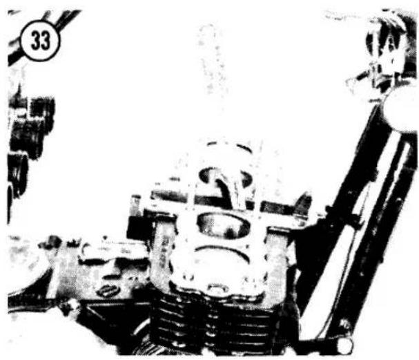

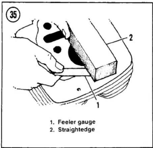


may be possible to salvage a cracked head with heliarc welding.
- Place a straightedge across the gasket surface at several points. Measure warp by inserting a feeler gauge between the straightedge and cylinder head at each location (Figure 35). There should be less warp than the limit in Table 1. If a small amount is present, the head can be resurfaced; have the job done by a machine shop.
Installation
- Check that the top surface of the cylinder block and the bottom surface of the cylinder head are clean before installing a new gasket. Make sure the oil passages are clear (Figure 36).
- Check that the 2 dowel pins (A, Figure 37) are installed at the outer front cylinder block studs, and that the oil control orifices (B) are in place with the small hole pointing up.
- Install 2 new O-rings (C, Figure 37).
- Install the cylinder head gasket. If one side of the gasket is marked "TOP" or "UP," that side faces up.
NOTE
The cylinder head gasket is not symmetrical. Make sure the gasket matches all holes in the head and the center cam chain tunnel cutaway.
- Check that the front cam chain guide is correctly installed (Figure 38).
- Lower the cylinder head onto the cylinder block studs, threading the cam chain up through the head. Tie the chain up or stick a screwdriver through it to keep it from falling down into the crankcase.
- Check that the cylinder head is fully seated against the cylinder block all around, then loosely install the 12 nuts (Figure 31).
- Tighten the cylinder head nuts evenly in 2 stages to the torque specified in Table 2. Follow the sequence shown in Figure 31.
- Install the 2 bolts at the rear of the cylinder (Figure 29) and 3 at the front (Figure 30). Torque the 5 cylinder head bolts as specified in Table 2.
- Oil and install the valve lifters and shims in the same locations from which they were
removed. Apply molybdenum disulfide grease if new parts are being used.
- After the engine has run and cooled off, retorque the cylinder head nuts and bolts to specifications (Table 2).
VALVES AND GUIDES
Valve Removal
See Figure 39. The valves can be removed after removing the cylinder head from the motorcycle. Use this procedure if you are going to disassemble the valves yourself. Otherwise, take the cylinder head to a Kawasaki dealer or qualified specialist for valve and valve seat work.

39
VALVE ASSEMBLY

- Valve lifter
- Shim
- Split keeper (2)
- Valve spring retainer
- Outer spring
- Inner spring
- Valve stem seal
- Spring seat
- Valve


-
Fit a valve spring compressor to the valve spring retainer and bottom of the valve head (Figure 40). Use the tool to press down the valve spring retainer and expose the split keepers on the valve stem. Remove the keepers.
-
Retract the compressor tool and remove the valve.
CAUTION
Remove any burrs from the valve stem grooves before removing the valve (Figure 41). Otherwise, the valve guides will be damaged when the valves come out.

- Remove the valve seal and valve spring seat (Figure 42) with needlenose pliers. Discard the old valve seal and install a new one; rubber seals harden and crack with age and they will never be easier to replace than now.
Valve/Seat Inspection
- Clean valves with a wire brush and solvent. Inspect the contact face of each valve for burning (Figure 43). Minor roughness and pitting can be removed by lapping the valve as described in this chapter. Excessive unevenness of the valve face shows that the valve is not serviceable. The valve face may be ground lightly on a valve grinding machine, but it is best to replace a burned or damaged valve with a new one.
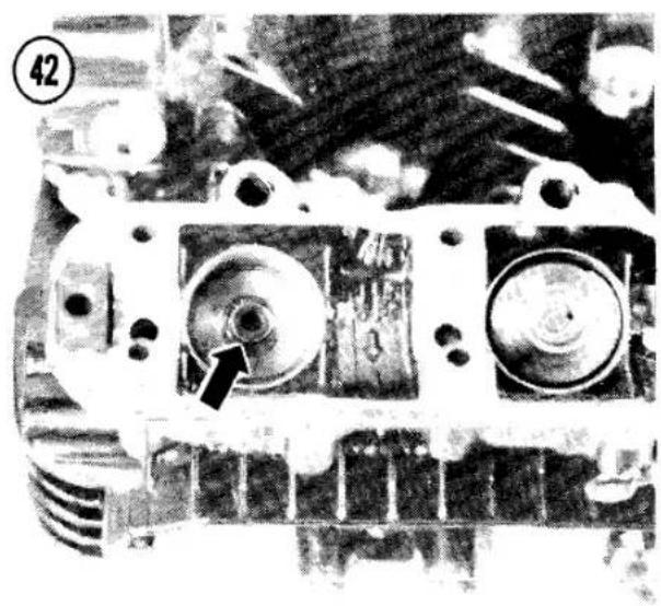

- Measure the vertical runout of the valve stem by rolling the stem on a piece of plate glass and measuring any gap with a feeler gauge. The runout should not exceed the service limit in Table 1.
- Measure valve stems for wear (Figure 44). Replace the valve if the stem diameter is less than the wear limit in Table 1.
- Remove all carbon and varnish from the valve guides with a stiff spiral wire brush.
- Inspect the valve/guide clearance; insert each valve in its guide. Hold the valve just slightly off its seat and rock it sideways, then at a right angle to the first check (Figure 45). If it rocks more than the limit in Table 1, the guide is probably worn and should be replaced.
- Take the cylinder head to a dealer and have the valve guides measured and replaced if necessary. Installation of new guides requires special installation and reaming tools.
- Inspect the valve seats. If worn or burned, they must be reconditioned with special cutting or grinding tools. This work should be done by your dealer or local machine shop. If you are performing the work yourself, see Table 1 at the end of this chapter for valve seat specifications (Figure 46).
- Seats and valves in near-perfect condition can be reconditioned by lapping with fine carborundum paste. Lapping, however, is always inferior to precision grinding or cutting.
Valve Lapping
Valve lapping is a simple operation which can restore the valve seal without machining if the amount of wear or distortion is not too great.
NOTE
Valve lapping is not a substitute for precision grinding or cutting of valves and their seats. Get a professional opinion on whether or not lapping will do the job before you settle for it.
- Coat the valve seating area in the head with a lapping compound such as Carborundum or Clover Brand.
- Insert the valve into the combustion chamber.
- Wet the suction cup of a lapping stick (Figure 47) and stick it onto the head of the


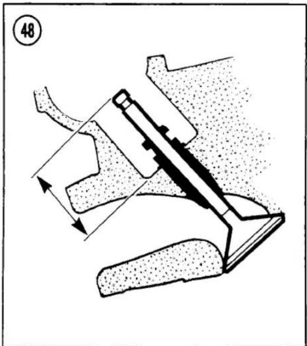


valve. Lap the valve to the seat by rotating the lapping stick back and forth by hand. Every 5 to 10 seconds, turn the valve 120° in the seat; continue lapping until the contact surfaces of the valve and the seat are a uniform grey. Do not remove too much material.
- Thoroughly clean the valves and cylinder head in solvent to remove all grinding compound. Any compound left on the valves or the cylinder head will end up in the engine and will cause serious damage.
- After the lapping is finished and the valves have been reinstalled in the head, the valve seal should be tested. Check the seal of each valve by pouring solvent into the intake and exhaust ports. There should be no leakage past the valve seat. If fluid leaks past any of the seats, disassemble that valve assembly and repeat the lapping procedure until there is no leakage.
Valve Stem Height
If the valve faces or seats were reground or recut, the valves will drop deeper into the cylinder head than before. Check valve stem installed height before you assemble the valves in the cylinder head. If the installed height is incorrect, you may not be able to obtain proper valve clearance with the available shims.
-
Insert the valve into the cylinder head and measure valve stem height (Figure 48).
-
If the stem height is more than specified in Table 1, the valve seat has worn or been ground too deep and the valve is too long for that cylinder. Install new valves.
CAUTION
Do not grind the valve stem end to correct the installed height. Grinding the valve stem end can cause the valve lifter to hit the spring retainer and drop the valve into the engine while running.
Valve Spring Inspection
As the valve springs wear, they become weaker. The valve springs must be checked for tension while compressed (Figure 49); have your dealer perform this inspection. Replace any spring that is weaker than the limit in Table 1 at the end of this chapter.
Measure each valve spring (inner and outer) for straightness by standing it on a flat surface and butting it against the vertical edge of a square (Figure 50). Install a new spring if the gap at the top is more than the limit in Table 1. Check the valve spring retainer and valve keepers. If they are in good condition, they can be reused.
Valve Installation
-
See Figure 39. Install the spring seats and new oil seals on the valve guides.
-
Coat the valve stems with molybdenum disulfide grease and insert the valves into the cylinder head.
- Install the 2 valve springs and the valve spring retainer.
NOTE
Install variable pitch springs with the closely wound coils toward the cylinder head (Figure 51).
- Fit a valve spring compressor to the valve spring retainer and the bottom of the valve head (Figure 40). Use the tool to press down the retainer and expose the keeper groove on the valve stem. Install the keepers and remove the spring compressor. Make sure the keepers are securely seated. Tap the stem end lightly with a hammer if necessary to jar the keepers into place.
CYLINDER BLOCK
The alloy cylinder block has pressed-in cylinder sleeves, which can be bored to 0.020 in. (0.5 mm) oversize and again to 0.040 in. (1 mm) oversize.
The cylinder block can be removed after removing the cylinder head.
Removal
- Pull the front cam chain guide up out of the block.
- Remove the 2 nuts at the rear of the cylinder block base (Figure 52) and the one at the front (Figure 53).
- Loosen the cylinder block from the crankcase; there is a cast-in pry point at the base (Figure 54). Use the widest tool that will fit the slot. Twist the tool; do not hammer into the opening.
- Pull the cylinder block straight up and off the pistons and studs.
- Stuff a clean rag into the crankcase under each piston to keep dirt or small parts from entering.
- Remove the 2 oil control orifices and O-rings from both sides of the crankcase.
- Remove the 2 Allen bolts and lift the rear cam chain guide up out of the crankcase.


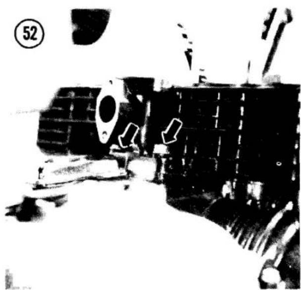


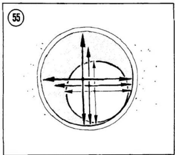
Cylinder Inspection
- Do not remove the carbon ridge at the top of the cylinder bore unless you are going to install new piston rings or bore or hone the cylinder. The ridge helps the top ring's compression seal.
- Check the cylinder walls for scratches; if evident, the cylinders should be rebored.
- Measure the cylinder bores, with a cylinder gauge or inside micrometer, at the points shown in Figure 55. Measure 2 ways—in line with the piston pin and at a right angle to the pin. If any measurement exceeds the wear limit in Table 1 or if the taper or out-of-round is greater than 0.002 in. (0.05 mm), the cylinders must be rebored to the next oversize and new pistons and rings installed. The liner can be bored oversize twice, first to 0.020 in. (0.5 mm) and again to 0.040 in. (1.0 mm). Rebore all cylinders even though only one may be faulty.

NOTE Get the new pistons before you have the cylinders bored. You'll need them to achieve proper piston/cylinder clearance.
- Inspect the cam chain guides (Figure 56). Replace them if visibly damaged or if worn deeper than the service limit in Table 1 (Figure 14).
Installation
- Check that the top surface of the crankcase and the bottom surface of the cylinder block are clean before installing a new gasket. Make

57

60
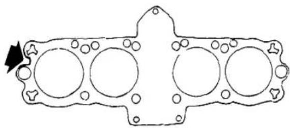


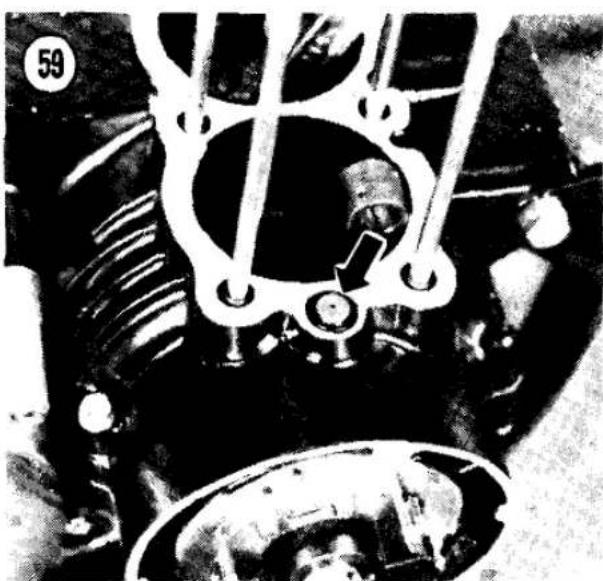
62

Cut away this portio

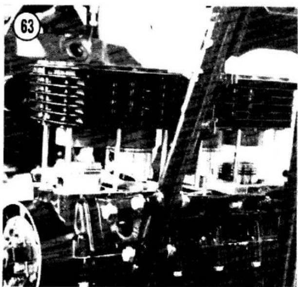


sure the oil passages at either end of the cylinder block are clear (Figure 57).
- Install the rear cam chain guide assembly (Figure 58); use Loctite on the 2 Allen bolts.
- Install the 2 oil control orifices and new O-rings at either side of the crankcase (Figure 59). The end of the orifice with the small hole faces up.
- Check the studs to the right of the cam chain tunnel. If there are O-rings on the studs, remove them and install new ones; not all models have these O-rings.
- Install a new cylinder base gasket on the crankcase; the notched end of the gasket goes toward the left side of the crankcase (Figure 60).
- Install a piston holding fixture under the 2 inner pistons (Figure 61).
NOTE
You can easily make a simple piston holding fixture out of wood. See Figure 62.
- Lightly oil the piston rings and cylinder walls.
- Carefully slide the cylinder block down over the studs, threading the cam chain up through the block (Figure 63). Tie the chain up or stick a screwdriver through it to keep it from falling down into the crankcase.
- Rock the cylinder block and slide it down over the inner 2 pistons and rings. Compress each piston ring with your fingers as the
cylinder starts to slide over it, then slide the block down over the outer pistons.
NOTE
If the rings are hard to compress, you can use a large hose clamp as a cheap, but effective piston ring compressor (Figure 64).
- Remove the piston holding fixture and push the cylinder block down until it seats on the crankcase. Check that the cylinder block is fully seated against the crankcase all around.
- Install the 2 nuts at the rear of the cylinder base (Figure 52) and the one at the front (Figure 53) and torque them as specified in Table 2.
PISTONS AND RINGS
The pistons can be removed after removing the cylinder block. With the pistons off, the connecting rods can be inspected without separating the crankcase halves.
Each piston has 3 rings. The top 2 rings are compression rings, to prevent compression blowby into the crankcase. The bottom ring is an oil control ring, to keep excess oil out of the combustion chamber. Some bikes have a 1-piece oil control ring and some have a 3-piece oil control ring consisting of 2 flat rails with an expander in between.
Piston Removal
- Lightly mark the top of the piston with a "1", "2", "3" and "4" so that each will be
reinstalled in the original cylinder. The No. 1 cylinder is on the left.
- Before removing the piston, hold the rod tightly and rock the piston as shown in Figure 65. Any rocking motion (do not confuse with the normal side-to-side sliding motion) indicates wear on the piston, piston pin, connecting rod small bore or more likely a combination of all three. If there is detectable rocking, install new pistons and pins.
- Pry out one or both piston pin circlips with an awl (Figure 66). The circlip can spring out forcefully, so protect your face.
- Push the piston pin out the side of the piston from which you removed the circlip. The pin will probably slide right out. Remove the piston; keep each piston pin inside its piston, so they can be reassembled in the original sets.
CAUTION
Do not try to hammer the pin out. You could bend the connecting rod or damage the rod bearings.
NOTE
It may be necessary to heat the piston slightly with a rag soaked in hot water or use a homemade tool to push the pin out, as shown in Figure 67.
- After you remove the piston, remove the top ring. Spread the ends with your thumbs just enough to slide it up over the piston (Figure 68). Repeat for the remaining rings.
WARNING
The rail portions of a 3-piece oil scraper can be very sharp. Be careful when handling them to avoid cut fingers.
Piston Inspection
- Carefully clean the carbon from the piston crown with a chemical remover or with a soft scraper.
- Clean the carbon and gum from the ring grooves with a broken ring or a groove cleaner (Figure 69). Any deposits left in the grooves will prevent the rings from seating correctly and may result in piston damage. Inspect the grooves carefully for burrs, nicks or broken or

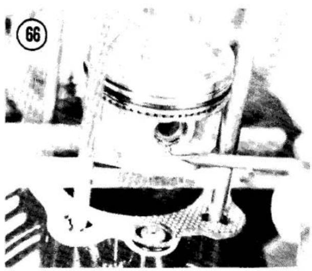

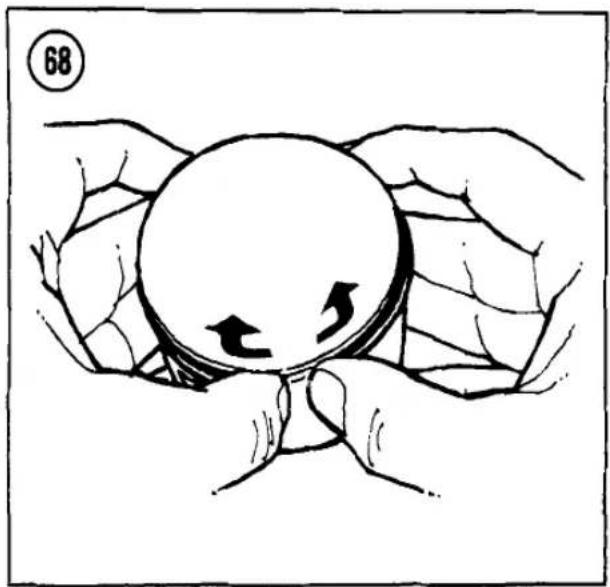
cracked lands. Examine each ring groove for burrs, dented edges and wear. Pay particular attention to the top compression ring groove, as it usually wears more than the others.
-
To check piston wear, measure the outside diameter of the piston with a micrometer. Take the measurement 3/16 in. (5 mm) above the bottom of the piston skirt, at a right angle to the piston pin bore (Figure 70). If the diameter of the piston measures less than the wear limit in Table 1, have the piston reconditioned or install a new piston.
-
Measure piston-to-cylinder clearance.
Piston/Cylinder Clearance


The most accurate way to check piston/cylinder clearance is to measure the inside diameter of the cylinder just above its bottom edge where it will have undergone the least amount of wear, then subtract the piston diameter as measured in Piston Inspection, Step 3. The clearance should be within the range specified in Table 1.
You can also measure installed piston/cylinder clearance with a feeler gauge near the bottom of the cylinder (Figure 71). The piston should be just free enough to slide with a light push (with no rings on the piston). This method is not as accurate as micrometer measurement calculation.
If a cylinder has not worn past the acceptable inside diameter limit and installing a new piston will bring the clearance within

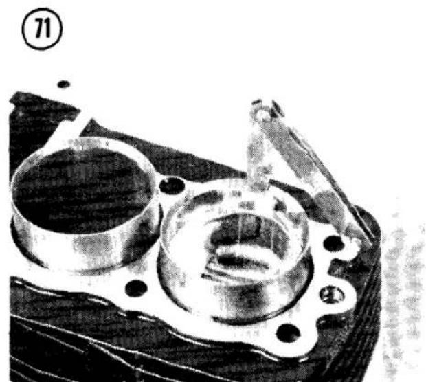
tolerance, the cylinder block need not be bored. However, in no case should the piston/cylinder clearance be less than the minimum.
Piston Ring Inspection
Measure the top 2 rings for wear by inserting each into the bottom of the cylinder where the cylinder is least worn. Seat the ring squarely in the cylinder by pushing it in slightly with the top of a piston. Measure the installed end gap with a feeler gauge (Figure 72). A new ring's gap should be no smaller than the limit in Table 1.
If the gap is smaller than specified, hold a small flat file in a vise, grip the ends of the ring with your fingers and enlarge the gap to the required minimum (Figure 73). As old rings wear, the gap will increase. Discard any rings whose installed gap exceeds the limit in Table 1. Always install new rings when installing new pistons or when you have any doubt about the condition of the rings.
Roll each ring around in its piston groove to make sure there is no binding (Figure 74). Check the side clearance of each ring with a feeler gauge (Figure 75). Refer to Table 1. If the clearance is incorrect, replace the pistons, rings or both.
Connecting Rod Inspection
After removing the pistons, the connecting rods can be inspected without removing them from the engine.
-
Measure the ID (inside diameter) of the small end of the connecting rod with a snap gauge and micrometer (Figure 76). If the ID is larger than the limit given in Table 1, install a new connecting rod (see Crankshaft Disassembly in this chapter).
-
Check the rod for obvious damage such as cracks and burns.
-
Check connecting rod big-end side clearance with feeler gauges (Figure 77). If the clearance exceeds the limit in Table 1, replace the connecting rod. If the clearance still exceeds the wear limit with a new connecting rod, the crankshaft should be replaced.
-
Check the connecting rod big-end radial (up-and-down) clearance; you can make a preliminary inspection by turning the
crankshaft until the crankpin is at TDC (top dead center).
CAUTION
If the crankshaft must be rotated, pull up on the cam chain and keep it taut while turning the crankshaft. If the chain is slack, it may jam up at the crankshaft and damage the chain and the sprocket.
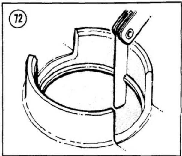

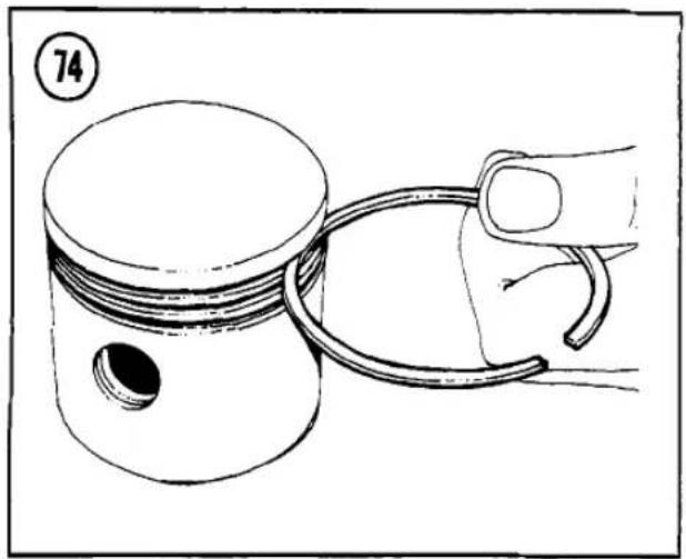



Grasp the connecting rod firmly and pull up on it. Tap sharply on the top of the rod with your free hand. If the bearing and crankpin are in good condition, there should be no movement felt in the rod. If movement is felt or if there is a sharp metallic click, measure the radial clearance with Plastigage as described under Crankshaft Inspection in this chapter.
Piston Installation
- Spread the ends of the rings with your thumbs, or use a ring expander tool, and install them in the proper piston groove. Note the following.
a. The side of the ring with a letter or number mark faces up (Figure 78). If there is no mark, either side can face up.
b. The top ring has a square cross-section and is narrower than the second ring; it is sometimes copper colored, with a chrome outer edge. The second ring has a
tapered outer edge (Figure 79).
- Coat the connecting rod holes and piston holes with clean engine oil.
NOTE
When assembling used parts, be sure to install each piston and pin on the same rod from which it was removed.
- Oil the piston pin and push it in the piston until the end extends slightly beyond the inside of the boss (Figure 80).
- Place the piston over the connecting rod with the arrow on the top of the piston pointing forward (Figure 81). Line up the pin with the rod small end and push the pin into the piston until it is even with the circlip grooves.
NOTE
It may be necessary to heat the piston slightly with a rag soaked in hot water or use a homemade tool to push the pin in (Figure 67).


CAUTION
Do not try to hammer the pin in. You could bend the connecting rod or damage the rod bearings.
- Install new circlips where removed. After installing each circlip, rotate it so that the gap lies at the bottom or top. Make sure that the clips are fully seated in the grooves.
CAUTION
Never reuse an old circlip. It becomes weak in the process of removal and could work loose and cause serious engine damage.
- To minimize blowby, rotate the top and bottom ring on each piston so that the ring openings face forward. Rotate the second ring so that its opening faces the rear of the engine. With 3-piece oil rings, the 2 rails should each be offset about 30° to either side of the expander opening (Figure 82).
OIL COOLER
(KZ550-D)
The KZ550-D is equipped with an oil cooler mounted in front of the engine (Figure 83). The cooler must be disconnected when the engine is removed from the frame or when the oil pan is removed.
Removal/Installation
- Put the bike up on its centerstand and put an oil drain pan under the engine.
- Drain the engine oil (see Chapter Three, Engine Oil and Filter).
- Remove the 4 oil cooler line mounting bolts at the front of the oil pan (Figure 84).
- Remove the 4 oil cooler mounting bolts and washers (Figure 83). Each bolt has an inner sleeve and a rubber grommet.
- To disconnect the oil cooling lines, hold the fitting on the bottom of the cooler with a wrench to keep it from tearing out of the cooler and loosen the cooling line nut.
- To install the cooler, reverse the removal steps. Note the following:
a. Inspect the oil cooler fitting O-rings and install new ones if damaged.
b. The return line from the right side of the oil cooler goes to the upper hole in the oil pan and the supply line from the left side of the oil cooler goes to the lower hole.
c. Torque the mounting bolts as specified in Table 2.
d. Add engine oil; see Engine Oil and Filter in Chapter Three. Recheck the oil level after the engine has run a short time and add oil if necessary.
ENGINE REMOVAL/INSTALLATION
Engine removal and crankcase separation are required for repair of the bottom end (crankshaft, connecting rods and bearings), transmission and shift drum/forks. Although the following parts can be left attached for engine removal, we recommend that you remove them first; it makes the engine much lighter to handle. Also, while the engine is in the frame you can use the rear brake to lock the drive train when required, instead of resorting to makeshift or expensive tools:
a. Top end (camshafts, cylinder head, cylinder block, pistons)
b. Alternator rotor and electric starter (refer to Chapter Eight)
c. Clutch hub and plates (refer to Chapter Five)

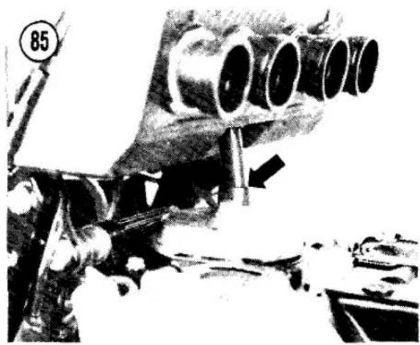

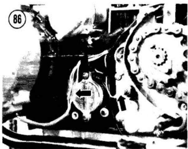
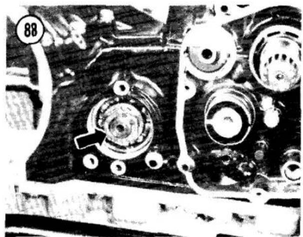
d. Shift linkage (refer to Chapter Six)
e. Engine sprocket (refer to Chapter Six)
NOTE
Alternator rotor removal is not essential unless you plan to replace the rotor or the crankshaft seals.
Once the engine is removed from the frame, some parts (like the alternator rotor, secondary shaft nut and clutch hub nut) cannot be removed from the engine without special tools or locking techniques.
If you only need to repair the transmission, removal of the engine top end is not necessary.
Removal
- Drain the engine oil and discard it. Don't reuse old oil.
-
Disconnect the breather hose that runs from the air cleaner housing to the breather cap (Figure 85).
-
Disconnect the alternator leads and the neutral switch lead (Figure 86).
- Remove the engine sprocket cover dowel pins for clearance when removing the engine (A, Figure 87).
- Remove the clutch pushrod (B, Figure 87).
- To keep from bending the shift linkage, remove the shift linkage cover and linkage; see Shift Linkage Removal in Chapter Six.
- Remove the secondary shaft bearing cap from the alternator side of the engine.
- Loosen the secondary shaft nut (Figure 88).
NOTE
While the engine is in the frame, you can shift the engine into gear and lock the drive train with the brake pedal. There will be considerable play in the rubber damper, but the nut will loosen.
- Remove the ignition timing cover at the right end of the crankshaft, then remove the 3


timing plate screws (Figure 89) and the pickup coil or contact breaker point assembly.
- Remove the rear brake light switch (A, Figure 90).
- Disconnect the battery ground lead at the right rear side of the engine (B, Figure 90).
- Remove the right footpeg.
13A. Models with rear drum brake: Remove the brake pedal or disconnect the rod and push the brake pedal down below the frame tube.
13B. Models with rear disc brake: Remove the 2 rear master cylinder mounting bolts (Figure 91), then push the brake pedal down below the frame tube. - On the KZ550-D: Remove the 4 oil cooler line mounting bolts at the front of the oil pan (Figure 84).
- Take a final look all over the engine to make sure everything has been disconnected.
- Loosen, then remove, all engine mounting nuts and bolts on both sides of the engine (Figure 92 and Figure 93).
WARNING
Keep your hands clear as you remove the bolts. The engine can easily smash your fingers.
NOTE
Bolt removal will be easier if you jack or lever the engine up slightly to take the weight off the bolts.
- Pull the engine up slightly and to the right side so that it clears the lower right front and rear mounting brackets. Take the engine to a work bench for further disassembly.
WARNING
If the recommended parts have not been removed, 2 people are required to safely remove the engine from the frame.
Installation
If you have removed the recommended parts listed at the beginning of Removal, leave them off until you have installed the bare engine in the frame. It will be easier to handle the engine and to tighten the rotor bolt, clutch hub nut and secondary shaft nut.
- Install the engine through the right side of the frame.
- Install the 2 right and one left engine mounting brackets loosely (remember the lockwashers).
- Lift the engine and install the 6 long bolts with locknuts. Use a locking agent such as Loctite Lock N' Seal on all engine mounting bolts and nuts. The upper rear bolt has 2 spacers.
- Torque the mounting bracket nuts, then the engine mounting nuts as specified in Table 2.
NOTE
Some engines have shims at the engine mounting bolts to take up play resulting from manufacturing variations. Check all mating surfaces after you torque the engine mounting bolts. If there is a gap between the engine and frame, add shims to take up any slack and provide a rigid engine/frame assembly.
- On the KZ550-D, inspect the oil cooler fitting O-rings and install new ones if damaged. The return line from the right side of the oil cooler goes to the upper hole in the oil pan and the supply line from the left side of the oil cooler goes to the lower hole. Torque the mounting bolts as specified in Table 2.
6A. Models with rear drum brake: Install the brake pedal or connect the brake rod.
6B. Models with rear disc brake: Install the 2 rear master cylinder mounting bolts (Figure 91) and tighten them securely.
7. Install the shift linkage and the linkage cover; see Shift Linkage Installation in Chapter Six.
8. Install the sprocket cover dowel pins (A, Figure 87) and the clutch pushrod (B).
9. Install the engine sprocket and sprocket cover; see Engine Sprocket Installation in Chapter Six. You can now use the rear brake to lock the engine while tightening the sprocket nut, alternator rotor bolt, clutch hub nut and secondary shaft nut.
10. Install the clutch; see Clutch Installation in Chapter Five.
11. Install the secondary shaft nut (Figure 88) and torque the nut as specified in Table 2.
NOTE
While the engine is in the frame, you can shift the engine into gear and lock the drive train with the brake pedal. There will be considerable play in the rubber damper, but the nut will tighten.
- Install the alternator side bearing cap with a wiring clamp (Figure 94).
- Install the alternator and electric starter as described in Chapter Eight.
- Install the top end (pistons, cylinder block, cylinder head, camshafts and valve cover) as


described in this chapter. Follow the Installation procedures when given separately or reverse the Removal procedures when separate installation procedures are not given. Do not omit any steps. Note the following.
a. Secure the ignition timing leads in the clamps attached to the lower right side of the engine (Figure 95).
b. Route the alternator and starter leads behind the shift mechanism cover tabs (Figure 96).
c. After connecting multiple-pin plastic connectors, make sure none of the male pins have popped out of place. Tug on the wires to find a loose pin and push loose pins back into place until you feel the locking tang seat fully.
d. The oil pressure switch lead is blue/red.
e. The neutral switch lead is light green.
f. The rear brake light switch leads are blue and brown.
g. The No. 1 and 4 ignition coil goes on the left. The black lead goes to the left coil and the green lead goes to the right coil. The yellow/red wires can go to either coil terminal.
h. Check that the engine oil drain plug is torqued as specified in Table 2 and add engine oil to the crankcase; see Engine Oil and Filter in Chapter Three.
i. Adjust the throttle cables, ignition timing (on contact breaker point models), clutch, drive chain, rear brake and rear brake light switch as described in Chapter Three.
WARNING
Make sure none of the control cables or wires are stretched or pinched when the handlebars are turned from lock to lock.
CAUTION
Do not hurry to start or ride the motorcycle yet. You have invested a lot of time, energy and money at this point. Do not take a chance on serious injury or mechanical damage. Thoroughly check and recheck all parts and controls on the motorcycle. Make sure all cables are correctly routed, adjusted and secured and all bolts and nuts are properly tightened. Position all cables away from the exhaust system.

j. Start the engine and check for leaks.
OIL FILTER BYPASS VALVE
The oil filter bypass valve is inside the oil filter mounting bolt. If the oil filter becomes so dirty that it blocks oil flow to the engine, the bypass valve routes unfiltered oil directly to the engine.
To remove the bypass valve, remove the oil filter. The bypass valve cannot be disassembled without damaging it, but you can push on the end of the bypass ball inside the valve (Figure 97) to make sure it moves freely inside the valve.
OIL PUMP
Operation
The trochoid oil pump is geared to the secondary shaft. The double rotor pump pulls oil through a coarse mesh screen and pushes it through the oil filter to trap fine particles. If the filter becomes clogged, a bypass valve routes the oil—still dirty—around the filter.
From the filter, one oil line goes to the oil pressure switch (Figure 98) and the relief valve in the oil pan (Figure 99). The pressure switch turns on the low oil pressure warning light when the oil pressure drops below a safe minimum. The relief valve limits engine oil pressure by dumping oil back into the crankcase when the pump pressure exceeds the limit in Table 1.
The filtered oil follows several distribution paths:
a. One route goes to the crankshaft main bearings and big-end bearings, the spray from which lubricates the cylinder walls and the piston pins.
b. One route goes through an orifice and leads to the camshaft journals; after the oil leaves the camshaft journals it lubricates the cam lobes and valve lifters.
c. One route goes through a spray nozzle to the primary drive chain.
d. One route goes through an orifice to the secondary shaft and starter clutch.

99

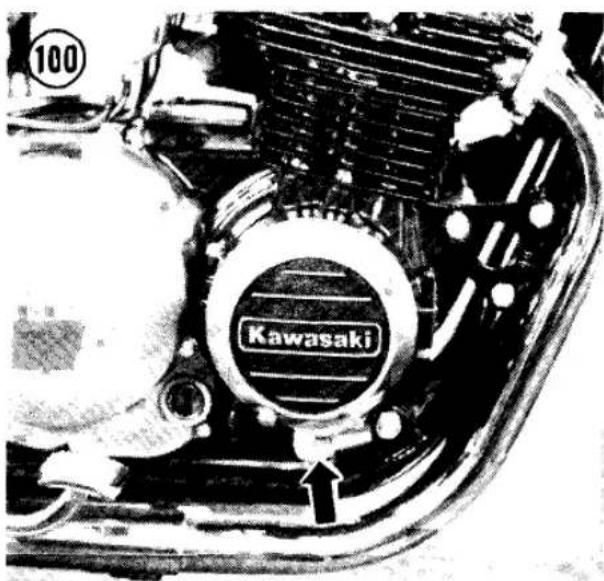

e. One route goes through an orifice to the transmission main shaft and output shaft bearings, then through the shafts to the gear bushings.
Oil Pressure Check
To check the operation of the oil pump and relief valve, start with a cold engine. Remove the plug from the oil pressure check point on the right-hand side of the crankcase (Figure 100) and attach an oil pressure gauge (Kawasaki has a special gauge available).
Check the relief valve by starting the engine and observing the cold oil pressure as you increase engine speed. If the cold oil pressure exceeds the upper limit in Table 1, the relief valve may be stuck closed. If the cold oil pressure is less than the lower limit when the engine speed is above about 5,000 rpm, the relief valve may be stuck open. If you suspect the relief valve is faulty, remove it as described in Oil Pump Removal. Check that the internal ball slides smoothly when pushed away from its seat (Figure 99) and that the ball seats fully when released.
Check the oil pump operation by running the engine long enough to warm the oil to normal operating temperature. The oil pressure should be as specified in Table 1. If the oil pressure is
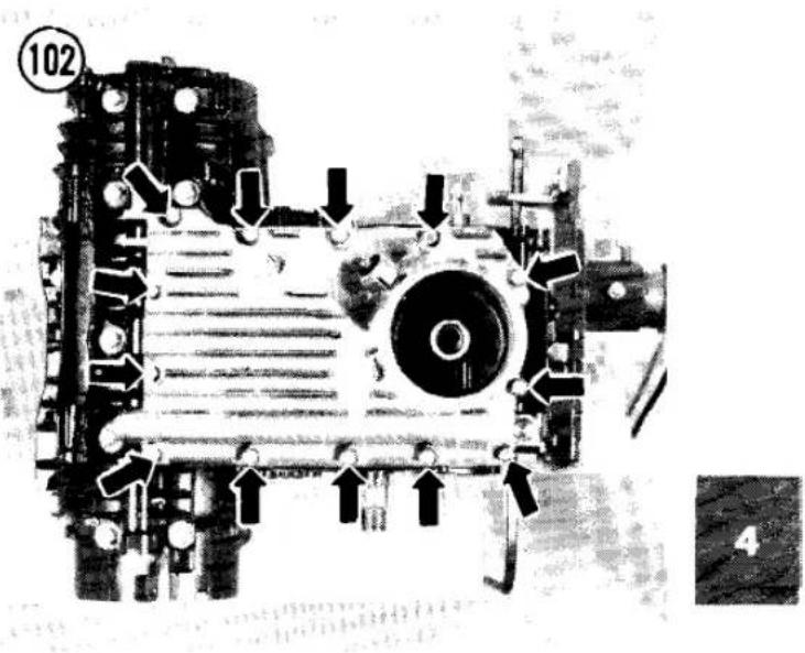
very low, inspect the oil pump, then the oil distribution routes.
Oil Pump Removal
The oil pump can be removed without removing the engine from the frame. For clarity, the engine is shown removed.
- Drain the engine oil and remove the oil filter.
- Remove the exhaust system; see Exhaust System Removal in Chapter Seven.
- On the KZ550-D, remove the 4 oil cooler line mounting bolts at the front of the oil pan (Figure 101).
- Remove the 13 bolts and washers that mount the oil pan to the crankcase (Figure 102). Remove the oil pan, gasket and 3O-rings.
- Remove the clutch assembly; see Clutch Removal in Chapter Five.
- Remove the one bolt and 2 screws that mount the oil pump to the right-hand side of the crankcase (Figure 103). Pull out the oil pump assembly.
Disassembly/Inspection/Assembly
- See Figure 104. Inspect the pump body for cracks.
- Remove the circlip and the washer from the pump shaft (A, Figure 105).
- Remove the 3 pump cover screws (B, Figure 105) and the cover and gasket.
103

105

104
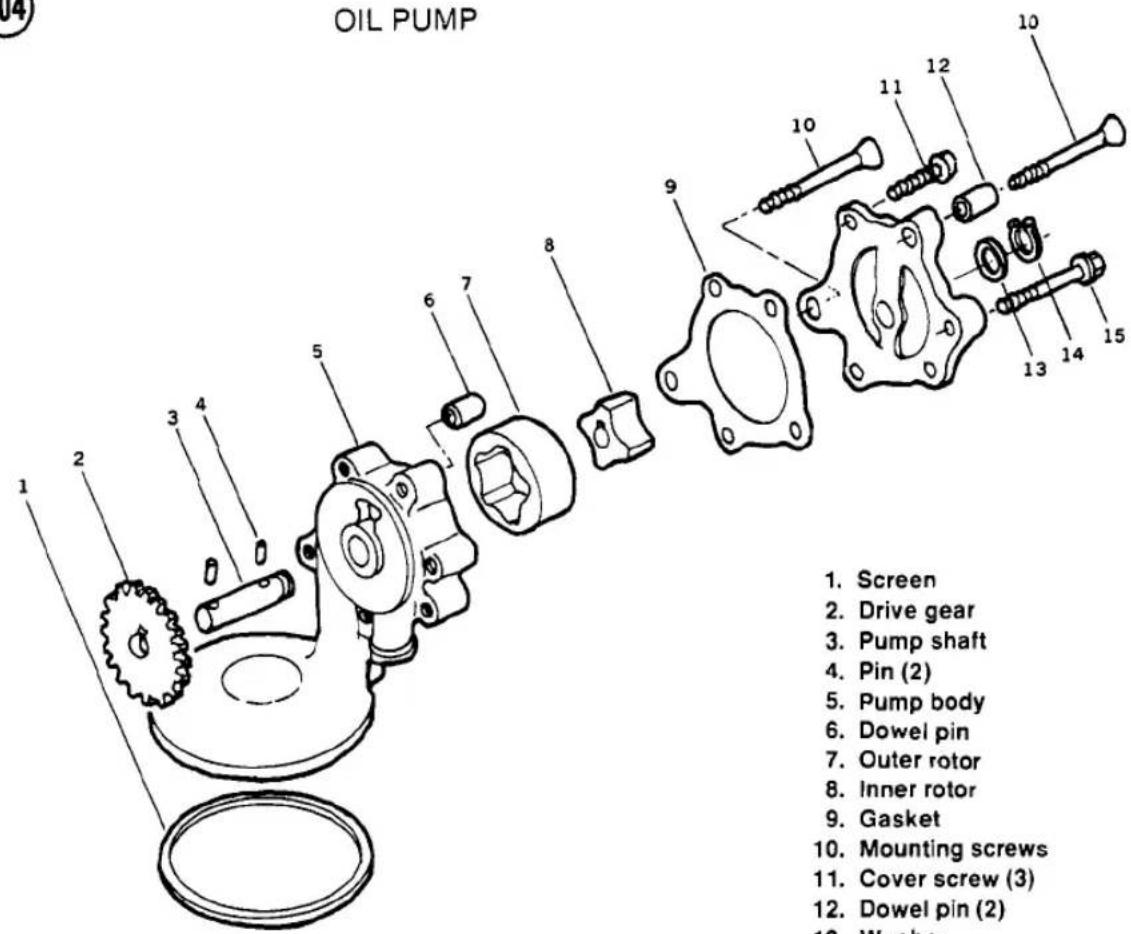
- Screen
- Drive gear
- Pump shaft
- Pin (2)
- Pump body
- Dowel pin
- Outer rotor
- Inner rotor
- Gasket
- Mounting screws
- Cover screw (3)
- Dowel pin (2)
- Washer
- Circlip
- Mounting bolt

109


- With feeler gauges, measure the minimum clearance between the inner rotor and the outer rotor (Figure 106).
- Measure the clearance between the outer rotor and the pump body (Figure 107).
- Measure the rotor side clearance with a straightedge and feeler gauge (Figure 108).
- Replace any parts whose wear exceeds the limits specified in Table 1.
- To assemble the oil pump, reverse the disassembly procedure. Note the following:
a. Check that the inner dowel pin is in place (Figure 109).
b. Use a new gasket.
c. After assembly, rotate the shaft to make sure it turns freely.
Oil Pump Installation

- Fill the pump with engine oil to prime it.
- Check that the 2 dowel pins are in place in the right-hand side of the crankcase (Figure 110).
- Install the pump in the engine. If it will not seat easily, rotate the drive gear enough to mesh it with the secondary shaft gear.
- Make sure the secondary shaft bearing retainer is in place, and install the 2 oil pump mounting screws and one bolt (Figure 111). Stake the mounting screws with a punch to lock them in place.
- Check the oil passage O-rings (Figure 112). Install new ones if damaged. The flat side of the O-ring faces the engine.


-
Install the oil pan with a new gasket. Tighten the mounting bolts in a crisscross pattern to the torque specified in Table 2.
-
On the KZ550-D, inspect the oil cooler fitting O-rings and install new ones if damaged. The return line from the right side of the oil cooler goes to the upper hole in the oil pan and the supply line from the left side of the oil cooler goes to the lower hole. Torque the mounting bolts as specified in Table 2.
-
Install the clutch assembly; see Clutch Installation in Chapter Five.
-
Install the exhaust system; see Exhaust System Installation in Chapter Seven.
-
Install the oil filter and add engine oil; see Engine Oil and Filter in Chapter Three.
CRANKCASE
Separation
If you only need to repair the transmission and are going to leave the crankshaft in place, removal of the engine top end is not necessary before separating the case halves.
Secondary shaft removal is part of this crankcase separation procedure.
- Remove the engine from the motorcycle as described in this chapter.
- Remove the secondary shaft bearing cap from the alternator side of the engine (Figure 113).
- Remove the secondary shaft nut.

- Remove the ignition advance unit; see Ignition Advance in Chapter Eight.
- Check that all parts outside of the crankcase have been removed from the engine (Figure 114 and Figure 115).
NOTE
Alternator rotor and ignition advance mechanism removal are not essential unless you plan to replace those parts or the crankshaft seals.
- Remove the 13 upper crankcase bolts (Figure 116).
- Turn the engine over and remove the oil pump as described in this chapter.
NOTE
Before you proceed, inspect the primary chain play. The primary chain should be replaced when it has more than 0.98 in. (25 mm) of slack (Figure 117). Inspect the secondary shaft sprocket carefully when you replace the chain. It is likely that both will need to be replaced at the same time.
- Tap on the alternator-side end of the secondary shaft with a soft driver until the other end pushes the bearing out (Figure 118).
- Pull the secondary shaft out of the clutch side of the engine.
- Remove the 17 lower crankcase bolts (Figure 119). Don't miss the bolt at the rear of the engine.
CAUTION
Make sure that you have removed all the fasteners. If the cases are hard to separate later, check for any fasteners you may have missed.
- Pry the crankcase halves apart, using the largest tool that will fit in the 4 pry points (Figure 120). There are pry points on both sides of the engine. If you encounter resistance, check for bolts you may have missed.
- Lift the bottom crankcase half off. See Chapter Six for transmission removal and inspection.
NOTE
Keep each crankshaft bearing insert in its original place in the crankcases. If you are going to assemble the engine with the original inserts, they must be installed exactly as removed in order to prevent rapid wear.
- Remove the starter clutch/secondary sprocket from the crankcase (Figure 121).
Inspection
Check the crankcase halves for cracks or fractures in the stiffening webs, around the bearing bosses and at threaded holes. While such damage is rare, it should be checked for, particularly following a major failure (such as piston breakage, bearing failure, gear breakage) or after a collision or hard spill in which the engine suffers external damage.
If cracks or fractures are found, they should be repaired immediately by a reputable shop experienced in and equipped to perform repairs on precision aluminum castings.
The upper and lower crankcase halves are machined as a pair; if one half is not usable, both must be replaced.
Bearing and Seal Replacement
The crankshaft oil seals should be replaced whenever the engine is disassembled. Seals should be installed with their marked side facing out of the engine. The secondary shaft bearing (A, Figure 122) and shift drum bearing (B) should be replaced if there is any doubt about their condition.

119


121

Since most bearings are installed with an interference fit, if possible heat the part in an oven to about 212° F ( 100° C) to aid bearing removal and installation.
CAUTION
Heating should be done in an oven and not with a torch; it's hard to get uniform heating with a torch, and the likelihood of warping the case is great.
If the bearings are hard to remove, they can be gently tapped out with a socket or piece of pipe the same size as the bearing outer race. Install the new bearing while the case is still hot. The marked side of a needle bearing faces out. If necessary, freeze the bearing before installing, to provide extra clearance.
Make sure that the bearings are not cocked in the hole and that they are seated properly.
NOTE
The alternator-side secondary shaft bearing should be 0.42-0.44 in. (10.7-11.3 mm) inside the outer surface of the crankcase boss.
If bearings are hard to remove or install, don't take a chance on expensive case damage. Have the work done by a Kawasaki dealer or competent machine shop.
SECONDARY SHAFT AND STARTER CLUTCH
Refer to Figure 123. The secondary shaft is an intermediate shaft driven by a chain from the crankshaft. The secondary shaft transmits power to the clutch ring gear and it turns the crankshaft when driven by the electric starter.


The driven sprocket on the secondary shaft has an internal rubber damper to smooth engine torque peaks. The starter drive clutch is mounted on the sprocket damper.
Secondary shaft removal is part of the crankcase separation procedure. This section describes shaft and starter clutch disassembly and inspection.
Primary Chain Inspection
The primary chain can be inspected after removing the oil pan. See Oil Pan Removal in this chapter. The primary chain should be replaced when it has more than 0.98 in. (25 mm) of up and down slack (Figure 117). Inspect the secondary shaft sprocket carefully when you replace the chain. It is likely that both will need to be replaced at the same time.
Disassembly/Assembly
- See Figure 123. Pull the starter clutch gear out of the starter clutch.
- Remove the 3 rollers, spring caps and springs from the clutch (Figure 124).
- Remove the 3 Allen screws that mount the clutch body to the rotor.
- The secondary shaft internal rubber dampers can be replaced after removing the circlip on the end of the driven sprocket.
123
SECONDARY SHAFT/STARTER CLUTCH
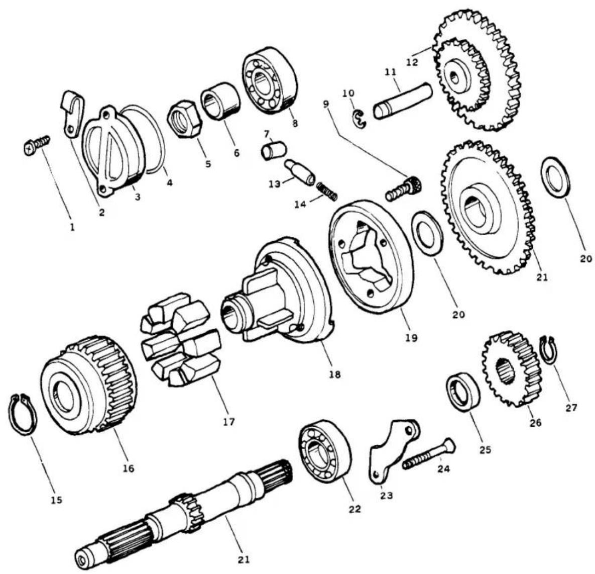
- Cover screw (2)
- Wiring clamp
- Bearing cap
- O-ring
- Nut
- Sleeve
- Roller (3)
- Ball bearing
- Allen bolt (3)
- Circlip
- Idler shaft
- Idler gear
- Spring cap (3)
-
Spring (3)
-
Circlip
- Driven sprocket
- Rubber dampers
- Inner coupling
- Starter clutch
- Washers
- Starter clutch gear
- Ball bearing
- Bearing retainer
- Screw (2)
- Spacer
- Secondary drive gear
- Circlip
124


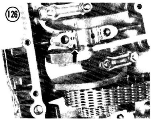
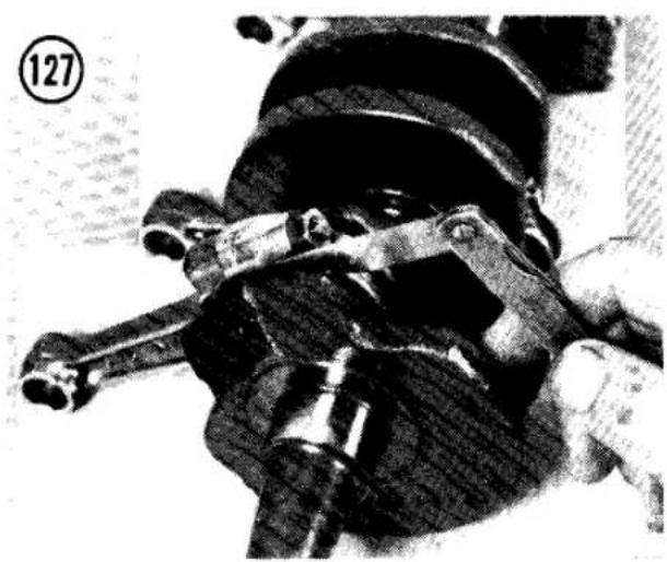
- Remove the circlip on the end of the secondary shaft (A, Figure 125) and remove the gear with a gear or bearing puller.
- Remove the spacer, then remove the bearing (B, Figure 125) with a gear or bearing puller.
- To assemble, reverse this procedure. Use a locking agent such as Loctite Lock N' Seal on the 3 starter clutch Allen bolts.
CRANKSHAFT AND CONNECTING RODS
The crankshaft is a 1-piece design that uses plain bearing inserts at the crankshaft main bearings and at the connecting rod big-end bearings. Once the crankshaft is removed, the cam chain and primary chain can be replaced.

Disassembly
- Split the engine cases; see Crankcase Separation in this chapter.
NOTE
Keep each bearing insert in its original place in the crankcases. If you are going to assemble the engine with the original inserts, they must be installed exactly as removed in order to prevent rapid wear.
-
Before removing the crankshaft assembly from the upper crankcase, measure the main bearing side clearance with feeler gauges, as shown in Figure 126. Pry the crankshaft toward one end, then toward the other, and measure the gap between the main bearing boss thrust face and the crankshaft flyweight thrust face. If play exceeds the limit in Table 1, the crankcase halves should be replaced as a set.
-
Lift the crankshaft assembly out of the engine case. Take off the cam chain and primary chain.
- Remove the oil seals from the ends of the crankshaft.
- Check connecting rod big-end side clearance with feeler gauges (Figure 127). If the clearance exceeds the limit in Table 1, the crankshaft and connecting rods should be replaced.
-
Before removing the rods, mark the rods and caps. Number them "1", "2", "3" and "4" starting at the alternator end of the crankshaft.
-
Remove each connecting rod's cap nuts (A, Figure 128), the cap and the rod. Keep each cap with its original rod, with the weight mark on the end of the cap matching the mark on the rod (B).
CAUTION
After removing the rod caps, remove the rods carefully to keep the rod studs from scratching the crankshaft journals.
NOTE
Keep each bearing insert in its original place in the crankcase, rod or rod cap. If you are going to assemble the engine with the original inserts, they must be installed exactly as removed in order to prevent rapid wear.
Inspection
- Clean the crankshaft oil holes with pipe cleaners (Figure 129); flush them thoroughly and dry. Lightly oil all bearing journals immediately to prevent rust.
- Carefully inspect all the main bearing and connecting rod bearing journals for scratches, ridges, scoring, nicks, etc. Very small nicks and scratches may be removed with fine emery cloth. More serious damage must be removed by grinding—a job for a machine shop.
- If these checks are satisfactory, take the crankshaft and connecting rod assembly to your dealer or local machine shop. They can check connecting rod bend and twist and crankshaft runout and inspect the parts for cracks. Check against the measurements given in Table 1 at the end of this chapter.
NOTE
When obtaining new connecting rods, make sure each pair (No. 1 and No. 2, or No. 3 and No. 4) has the same weight mark stamped on the side of the big end (B, Figure 128).
- Check all the main bearing and connecting rod big-end clearances as described in the following section.
Main Bearing Clearance Measurement
To check crankshaft journal/bearing clearance with Plastigage, the crankshaft must be installed with the journals and inserts dry. It
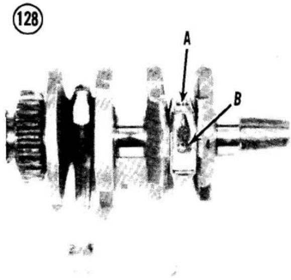
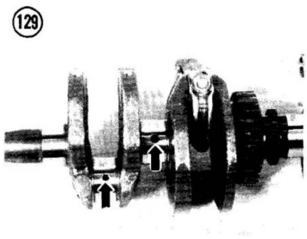

131

132

133

is very important not to turn the crankshaft while assembled dry. After checking clearance, remove the crankshaft and clean and lubricate the journals.
- Make a note of the bearing size (if any) stamped on the back of the insert. If the inserts are color-coded with paint on the edge, note the color.
- Check the inside and outside surfaces of the bearing inserts for wear, a bluish tint (burned), flaking, abrasion or scoring. If the inserts are good, they may be reused if clearance is satisfactory. If any insert is questionable, replace the entire set.
- Wipe any oil from the crankshaft main journals and the inserts.
- Set the upper crankcase upside down on the workbench. Place it on wood blocks to prevent damage to the cylinder studs.
- Install the main bearing inserts in the upper (Figure 130) and lower (Figure 131) crankcase halves. Make sure their locking tabs are seated in the notches (Figure 132).
NOTE
If the old inserts are reused, be sure they are installed in their original positions to prevent rapid wear.
- Install the crankshaft in the upper crankcase half.
- Place a strip of Plastigage over each main bearing journal parallel to the crankshaft.
NOTE
Do not put Plastigage over the oil holes. Do not rotate the crankshaft while the Plastigage strips are in place.
- Carefully turn the lower crankcase over and install it on the upper crankcase.
- Apply oil to the bolt threads and loosely install the 10 large crankcase bolts (Figure 133).
- Torque the 10 large bolts in 2 stages, as specified in Table 2, following the sequence numbers cast into the bottom of the engine next to the bolts.
- Remove the bolts in the same sequence you tightened them and remove the lower case half.
- Measure the width of the flattened Plastigage according to manufacturer's

instructions (Figure 134). The standard crankshaft main bearing clearance is 0.0009 in. (0.022 mm). The maximum (service limit) is 0.004 in. (0.10 mm).
- Compare both ends of the Plastigage strip. A difference of 0.001 in. (0.025 mm) or more indicates a tapered journal which should be reground. Confirm with micrometer measurement of the journal OD.
- If the clearance is larger than the service limit, measure the OD of the crankshaft main journal with a micrometer. The minimum main journal OD (service limit) is given in Table 1.
a. If the OD is smaller than the service limit, the crankshaft should be replaced.
b. If the OD is larger than the service limit, install new bearing inserts. Always replace all 10 inserts at the same time. Several different insert thicknesses are available and they are color-coded for size. Refer to Table 1 for insert thicknesses.
c. Recheck the clearance with the new inserts. The clearance should be less than the service limit and as close to standard as possible.
NOTE
You can install the thinnest new inserts, recheck clearance and install thicker inserts if the clearance wasn't correct, or you can calculate the required insert thickness:
- Assemble the crankcase halves without the inserts or crankshaft and measure the crankcase ID.
- Subtract the crankshaft main journal OD from the crankcase ID, then subtract the standard clearance—0.0009 in. (0.022 mm). The number you get will be twice the thickness of the required inserts.
-
Divide by 2 for the appropriate insert thickness.
-
Clean and oil the main bearing journals and insert faces.
- Install the bearing inserts in the crankcase halves. Make sure their locking tabs are seated in the notches.

NOTE
If the old inserts are reused, be sure they are installed in their original positions for minimum wear.
Connecting Rod Big-end Bearing Clearance
- Make a note of the bearing size (if any) stamped on the back of the insert. If the insert is color-coded with paint on the edge, note the color.
- Check the inside and outside surfaces of the bearing inserts for wear, a bluish tint (burned), flaking, abrasion and scoring. If the inserts are good, they may be reused if clearance is satisfactory. If any insert is questionable, replace the entire set.
- Wipe oil from the crankpin journals and the inserts.
- Install the inserts in the connecting rod and cap. Make sure their locking tabs are seated in the notches (Figure 132).
- Place a piece of Plastigage on one crankpin parallel to the crankshaft.
- Install the rod cap and torque the nuts as specified in Table 2.
NOTE
Do not place the Plastigage over the oil holes. Do not rotate the connecting rod while Plastigage is in place.
- Remove the rod cap.
- Measure the width of the flattened Plastigage according to manufacturer's instructions (Figure 134). The standard connecting rod big-end bearing clearance is 0.0016 in. (0.04 mm). The maximum (service limit) is 0.004 in. (0.1 mm).
- Compare both ends of the Plastigage strip. A difference of 0.001 in. (0.025 mm) or more indicates a tapered journal (which should be reground) or a bent or twisted rod. Confirm with micrometer measurement of the journal OD.
- If the clearance is larger than the service limit, measure the OD of the crankpin journal with a micrometer. The minimum crankpin journal O.D. (service limit) is given in Table 1.
a. If the OD is smaller than the service limit, the crankshaft should be replaced.
b. If the OD is larger than the service limit, install new bearing inserts. Always replace all 8 inserts at the same time. Several different insert thicknesses are available and they are color-coded for size. Refer to Table 1 for the insert thickness.
c. Recheck the clearance with the new inserts. The clearance should be less than the service limit and as close to standard as possible.
NOTE
You can install the thinnest new inserts, recheck clearance and install thicker inserts if the clearance wasn't correct or you can calculate the required insert thickness:
- Assemble the connecting rod and cap without the inserts and measure the rod big-end ID. The cap must be with its original rod, with the weight mark on the end of the cap matching the mark on the rod (B, Figure 128). Install the cap nuts finger-tight, then torque them as specified in Table 2.
- Subtract the crankpin journal OD from the rod big-end ID, then subtract the standard clearance-0.0016 in. (0.04 mm). The number you get will be twice the thickness of the required inserts.
-
Divide by 2 for the appropriate insert thickness.
-
Repeat for each connecting rod.
- Clean and oil the crankpin journals and insert faces.
- Install the bearing inserts in each connecting rod and cap. Make sure their locking tabs are seated in the notches (Figure 132).
NOTE
If the old inserts are reused, be sure they are installed in their original positions to prevent rapid wear.
Assembly
- Install the bearing inserts in each connecting rod and cap. Make sure their locking tabs are seated in the notches (Figure 132).

NOTE
If the old inserts are reused, be sure they are installed in their original positions to prevent rapid wear.
- Oil the rod bearing inserts and crankpins.
- Install each rod, one at a time, on the proper crankpin, with No. 1 starting at the alternator end of the crankshaft. The cap must be with its original rod, with the weight mark on the end of the cap matching the mark on the rod (B, Figure 128).
- Install the cap nuts finger-tight, then torque them as specified in Table 2.
- Install the remaining rods in the same manner.
CAM CHAIN INSPECTION
Pull the cam chain taut with about a 10 lb. (5 kg) tension and measure the length from the 1st pin to the 21st pin (Figure 135). If the chain is longer than the service limit given in Table 1, install a new chain.
PRIMARY CHAIN INSPECTION
The primary chain wear is inspected by measuring chain play with the crankshaft and secondary shaft installed in the engine (Figure 117); see Crankcase Separation in this chapter.


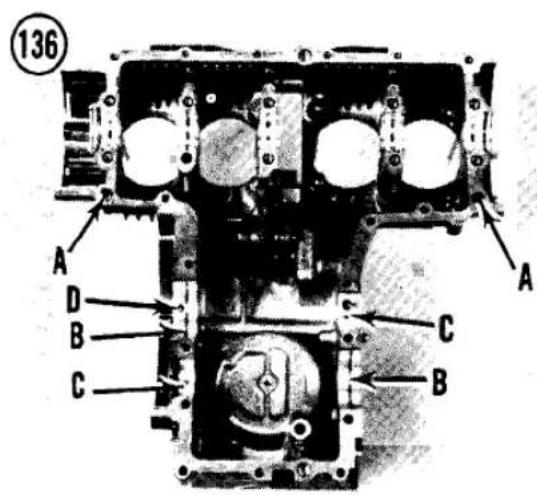
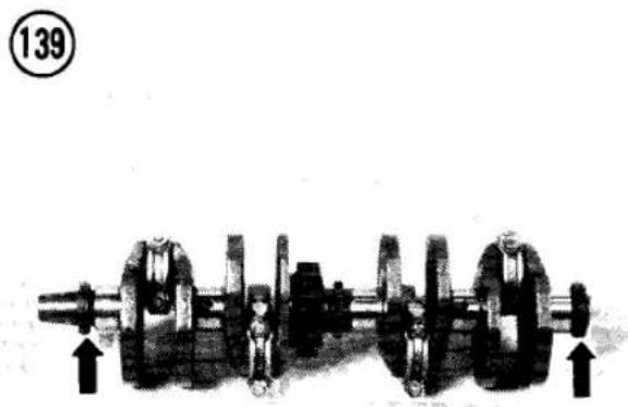


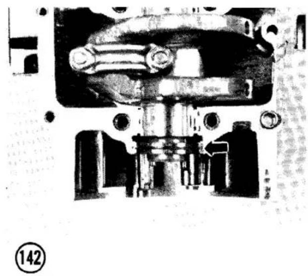

CRANKCASE ASSEMBLY
The crankcases should be assembled with the engine upside down.
CAUTION
Set the upper crankcase half on wood blocks to protect the cylinder studs.
- In the upper crankcase half, check that the 2 crankcase dowel pins (A, Figure 136), 2 transmission bearing alignment 1/2 rings (B), 2 transmission dowel pins (C) and the oil passage plug (D) are in place.
- Check that the starter idler gear is installed in the upper case half with the smaller sprocket pointing to the alternator side of the engine (Figure 137). Install the circlip on the idler gear shaft.
- In the lower crankcase half, check that all oil passages are clear and that the 2 oil control nozzles are in place (Figure 138).
- Install the main bearing inserts in the upper (Figure 130) and lower (Figure 131) crankcase halves. Make sure their locking tabs are seated in the notches.
NOTE
If the old inserts are reused, be sure they are installed in their original positions to prevent rapid wear.
- Install new left- and right-hand oil seals on the ends of the crankshaft (Figure 139); apply high temperature grease to the seal lips. The
arrow on the seal (A, Figure 140) must face out and must point in the direction of crankshaft rotation (clockwise when viewed from the right-hand side of the engine). The left-hand crankshaft seal (B, Figure 140) has a narrower body than the right-hand seal (C).
- Oil the main bearing inserts and crankshaft main journals.
- Position the cam chain and primary chain on the crankshaft.
- Install the crankshaft assembly with primary chain and cam chain in the upper crankcase half (Figure 141). The oil seal ribs must fit into the grooves in the crankcase (Figure 142).
- Put the thrust washer inside the starter clutch and turn the starter clutch gear while pushing it into the clutch and roller assembly. Install the starter clutch/secondary sprocket through the primary chain (Figure 143).
- Install the transmission shafts in the upper crankcase half; see Transmission Gears in Chapter Six. Align the transmission gears in the NEUTRAL position (Figure 144).
- Rotate the shift drum to the NEUTRAL position (Figure 145).
- Transmission test: This is an optional procedure to make sure the transmission has been assembled properly.
a. Carefully place the lower case half in position, fitting the shift forks in their proper gear grooves.
b. Seat the upper case half onto the lower and tap lightly with a plastic or rubber
143
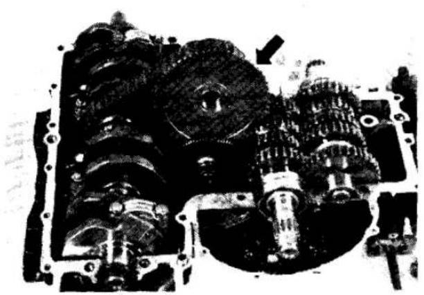
146
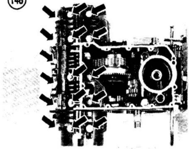
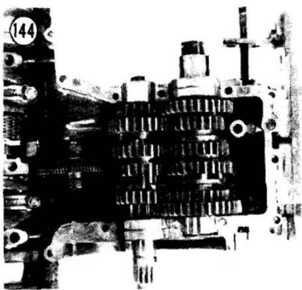


148
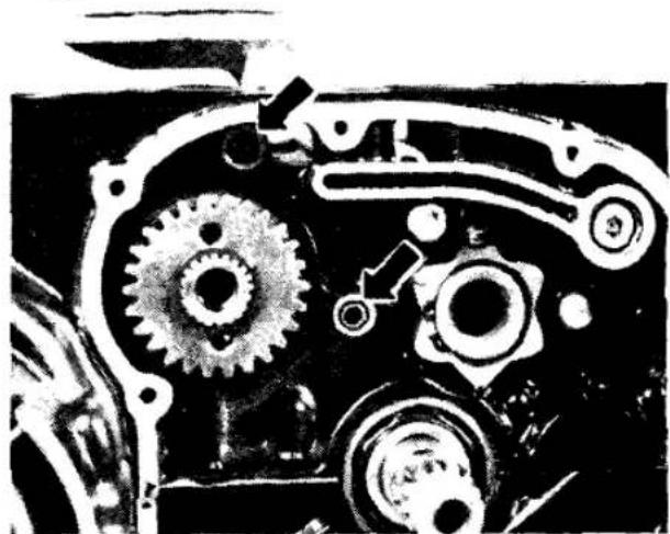
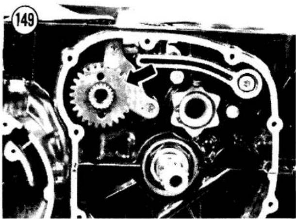
mallet—do not use a metal hammer or it will damage the cases.
c. Carefully rotate the shift drum while turning the output shaft. Check that all gears engage smoothly and that each gear position can be identified. You will have to spin the output shaft quickly to keep the "neutral finder" from locking you out of 2nd and higher gears. Refer to Chapter Six if the transmission does not work correctly.
d. Remove the lower case half.
- Make sure the crankcase mating surfaces are completely clean and dry.
- Apply a light coat of gasket sealer to the sealing surfaces of the bottom case half. Cover only flat surfaces, not curved bearing surfaces. Make the coating as thin as possible.
CAUTION
Do not block any oil passage with sealant.
- Carefully place the lower case half in position, fitting the shift forks in their proper gear grooves.
- Seat the upper case half onto the lower and tap lightly with a plastic or rubber mallet—do not use a metal hammer or it will damage the cases.
- Apply oil to the bolt threads and loosely install the 17 lower crankcase bolts (Figure 146). Don't miss the bolt at the rear of the engine.
NOTE
When installing crankcase bolts, check that each one sticks up the same amount before you screw them all in. If not,
you've got a short bolt in a long hole and vice versa.
- Torque the 10 large bolts in 2 stages, as specified in Table 2, following the sequence numbers cast into the bottom of the engine next to the bolts.
- Torque the 7 smaller bolts as specified in Table 2.
- Rotate the crankshaft to make sure the bearings are not too tight.
- Carefully rotate the shift drum while turning the output shaft. Check that all gears engage smoothly and that each gear position can be identified. You will have to spin the output shaft quickly to keep the "neutral finder" from locking you out of 2nd and higher gears. Refer to Chapter Six if the transmission does not work correctly.
- Insert the secondary shaft through the clutch side of the engine, through the thrust washer (Figure 147) and into the starter clutch assembly, aligning the shaft splines with the secondary sprocket splines.
- Before the secondary shaft is all the way in, check that the 2 oil pump dowels are in place (Figure 148) and hold the bearing retainer in place (Figure 149).
- Tap the secondary shaft into place with a large socket placed over the secondary drive gear until the clutch side bearing bottoms in the crankcase.
- Insert the alternator side bearing sleeve (Figure 150).
NOTE
Before proceeding, inspect the primary chain play as described in Crankcase Separation in this chapter.
NOTE
Secondary shaft nut tightening will be easier if you wait until the engine is installed in the motorcycle.
- Install the oil pump and oil pan; see Oil Pump Installation in this chapter.
- Turn the engine over and install the 13 upper crankcase bolts (Figure 151). Torque them as specified in Table 2.
- Install the ignition advance assembly and breaker point or pickup coil assembly as described in Chapter Eight.

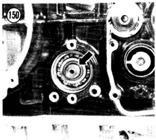

Table 1 ENGINE WEAR LIMITS
| Cam chain (20 link length) | 6.39 in. (162.4 mm) |
| Cam chain guide rubber wear depth | |
| Upper | 0.16 in. (4.0 mm) |
| Front | 0.20 in. (5.0 mm) |
| Rear | 0.12 in. (3.0 mm) |
| Cam lobe height | 1.396 in. (35.45 mm) |
| Camshaft journal/bearing | |
| cap clearance | 0.005 in. (0.13 mm) |
| Camshaft bearing ID | 0.869 in. (22.06 mm) |
| Camshaft journal OD | 0.864 in. (21.93 mm) |
| Camshaft runout | 0.004 in. (0.1 mm) |
| Compression (minimum) | 130 psi (9.0 kg/cm2) |
| Combustion chamber volume (from bottom of cylinder head) | 0.95 cu. in. (15.6 cc) |
| Connecting rod bend and twist per 4 in. (100 mm) | 0.008 in. (0.20 mm) |
| Connecting rod big-end clearance | |
| Radial | |
| Limit | 0.004 in. (0.1 mm) |
| Standard | 0.0016 in. (0.0405 mm) |
| Side | 0.020 in. (0.50 mm) |
| Connecting rod small end ID | 0.553 in. (14.05 mm) |
| Connecting rod journal OD | 1.298 in. (32.97 mm) |
| Connecting rod bearing insert thickness | |
| Green | 0.0587 in. (1.492 mm) |
| Black | 0.0586 in. (1.486 mm) |
| Brown | 0.0584 in. (1.483 mm) |
| Crankshaft main journal/bearing clearance | |
| Limit | 0.004 in. (0.10 mm) |
| Standard | 0.0009 in. (0.022 mm) |
| Crankshaft main journal OD | 1.258 in. (31.96 mm) |
| Crankshaft bearing insert thickness | |
| Brown | 0.0785 in. (1.993 mm) |
| Black | 0.0786 in. (1.997 mm) |
| Green | 0.0788 in. (2.001 mm) |
| Crankshaft side clearance | 0.014 in. (0.35 mm) |
| Crankshaft runout | 0.002 in. (0.05 mm) |
| Cylinder head warp | 0.002 in. (0.05 mm) |
| Cylinder bore ID | |
| KZ500 | 2.169 in. (55.10 mm) |
| KZ550 | 2.287 in. (58.10 mm) |
| Oil pressure @ 4,000 rpm @ 195°F (90°C) | |
| Standard | 28-36 psi (2.0-2.5 kg/cm2) |
| Relief valve (cold oil) | 63-85 psi (4.4-6.0 kg/cm2) |
| Oil pump | |
| Inner/outer rotor clearance | 0.012 in. (0.30 mm) |
| Outer rotor/body clearance | 0.012 in. (0.30 mm) |
| Rotor end play | 0.005 in. (0.12 mm) |
| Piston/cylinder clearance | |
| (standard) | 0.0008-0.0019 in. (0.020-0.047 mm) |
| Piston OD | |
| KZ500 | 2.157 in. (54.80 mm) |
| KZ550 | 2.276 in. (57.80 mm) |
| Piston pin hole ID | 0.5539 in. (14.07 mm) |
| Piston pin OD | 0.5496 in. (13.96 mm) |
| Piston ring/groove clearance | 0.006 in. (0.15 mm) |
| Piston ring thickness | 0.043 in. (1.10 mm) |
| (continued) | |

Table 1 ENGINE WEAR LIMITS (Continued)
| Piston ring groove width | |
| Top, second | 0.052 in. (1.33 mm) |
| Oil | 0.102 in. (2.60 mm) |
| Piston ring installed gap (limits) | 0.008-0.027 in. (0.2-0.7 mm) |
| Primary chain play (Tsubakimoto) | |
| Hy-Vo 3/8P-3/4W, 50 links) | 0.98 in. (25 mm) |
| Valve stem runout | 0.002 in. (0.05 mm) |
| Valve stem OD | |
| Intake | 0.213 in. (5.41 mm) |
| Exhaust | 0.212 in. (5.39 mm) |
| Valve guide ID | 0.220 in. (5.58 mm) |
| Valve/guide clearance (rocking method) | 0.010 in. (0.26 mm) |
| Valve head thickness | 0.020 in. (0.5 mm) |
| Valve seat width (standard) | 0.030 in. (0.75 mm) |
| Valve seat angles | 30°, 45°, 60° |
| Valve spring tension | |
| Inner | 36 lb. @ 0.91 in. (16.2 kg @ 23.1 mm) |
| Outer | 69 lb. @ 0.99 in. (31.3 kg @ 25.1 mm) |
| Valve spring squareness | 0.06 in. (1.5 mm) from vertical @ top of spring |
| Valve stem installed height (max.) | |
| Intake | 1.458 in. (37.03 mm) |
| Exhaust | 1.456 in. (36.98 mm) |
Table 2 ENGINE TORQUES
| Item | Ft.-lb. | Mkg |
| Alternator rotor bolt | 50 | 7.0 |
| Cam chain tensioner cap | 18 | 2.5 |
| Camshaft cap bolts | 8.5 | 1.2 |
| Camshaft sprocket bolts | 11 | 1.5 |
| Clutch hub nut | 100 | 13.5 |
| Clutch spring bolts | 90 in.-lb. | 1.0 |
| Connecting rod cap nuts | 17.5 | 2.4 |
| Crankcase bolts | ||
| Small | 90 in.-lb. | 1.0 |
| Large | 18 | 2.5 |
| Cylinder base nuts | 8.5 | 1.2 |
| Cylinder head | ||
| Bolts | 8.5 | 1.2 |
| Nuts | 16.5 | 2.3 |
| Cylinder base nuts | 8.5 | 1.2 |
| Engine mounting nuts | 30 | 4.0 |
| Engine mounting bracket nuts | 17.5 | 2.4 |
| Engine sprocket plate bolts | 90 in.-lb. | 1.0 |
| Ignition advance bolt | 18 | 2.5 |
| Neutral indicator switch | 11 | 1.5 |
| Oil cooler mounting bolts | 90 in.-lb. | 1.0 |
| Oil cooling line bolts | 90 in.-lb. | 1.0 |
| Oil cooling line nuts | 16.5 | 2.3 |
| Oil drain plug | 27 | 3.8 |
| Oil filter mounting bolt | 14.5 | 2.0 |
| Oil pan bolts | 90 inch-lb. | 1.0 |
| (continued) | ||
| Secondary shaft nut | 45 | 6.0 |
| Shift return spring pin | 18 | 2.5 |
| Spark plugs | 10 | 1.4 |
| Starter clutch Allen bolts | 25 | 3.5 |
| Valve cover bolts | 90 in.-lb. | 1.0 |

NOTE: If you own a 1982 or later model, first check the Supplement at the back of the book for any new service information.
CHAPTER FIVE
CLUTCH
The clutch can be serviced with the engine in the motorcycle or on a workbench. Generally, most service operations are easier with the engine in the motorcycle because the engine is held firmly.
Clutch wear limit specifications are given in Table 1 at the end of the chapter.
OPERATION
The clutch is a wet multi-plate type which operates immersed in the engine oil. It is mounted on the right-hand end of the transmission input shaft. The inner clutch hub is splined to the input shaft and the outer housing can rotate freely on the input shaft when the clutch release is actuated. The outer housing is driven by a gear on the end of the secondary shaft. The clutch release is mounted in the sprocket cover on the left side of the engine.
CAUTION
The clutch friction plates are bathed in the same oil you put in the engine. Do not use oil additives or you may cause clutch slippage.
Between the clutch inner hub and outer housing is a sandwich of clutch plates. Every other plate (including the inner and outer friction plates) is locked to the outer housing and must turn whenever it turns. The remaining metal plates are locked to the inner hub; when they turn, it turns. Outside this sandwich of clutch plates is the pressure plate. Coil springs push the pressure plate in against the rest of the plates. This pressure jams the plates together and friction locks the clutch hubs together, so that the crankshaft can turn the transmission input shaft.
To disengage the clutch, a clutch release mechanism lifts the pressure plate outward from the clutch. With the pressure gone, the outer housing and the friction plates locked to it continue to turn, but the metal plates and inner hub stop turning.
All of the clutch parts can be removed while the engine is mounted in the frame.
CLUTCH RELEASE MECHANISM
Routine cable free play and release adjustment are described in Chapter Three.
The clutch release mechanism is mounted inside the engine sprocket cover. The release consists of a release arm that rides on ball bearings inside the release housing. The clutch cable is attached to the arm; when pulled, it


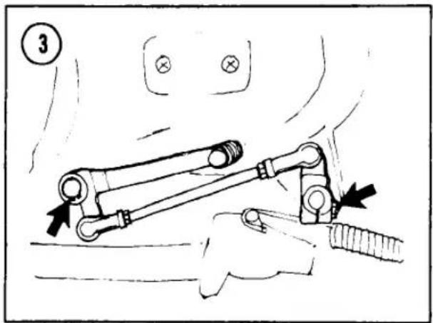
rotates the arm which moves toward the clutch. The adjusting screw in the arm then pushes against the clutch pushrod, which extends through the hollow transmission input shaft and releases the clutch pressure plate from the pack of friction and steel plates.
Disassembly/Assembly
Early models use a clutch release with 2 spiral gears riding on 11 ball bearings (Figure 1).
Late models use a clutch release with 3 ball bearings riding up ramps in the release arm.
- Place the bike on its centerstand.
- Remove the left footpeg bolt, lockwasher and the footpeg (A, Figure 2).
- Remove the shift pedal (B, Figure 2); remove the bolt, and spread the slot open with a screwdriver if necessary. If your bike has linkage between the shift pedal and shift shaft, remove the circlip at the pedal and remove all the linkage (Figure 3).
- Remove the 2 bolts securing the starter motor cover, and remove the cover and gasket (Figure 4).
- Remove the 4 bolts securing the engine sprocket cover and remove the cover (Figure 5). Be careful not to damage the shift shaft oil seal.
- If you want to detach the clutch cable, remove the clutch release lever cotter pin (Figure 6). Remove the cable tip from the lever.
7A. On late models:
a. Pull the release arm out of the release housing.
b. Remove the 3 ball bearings and their cage (Figure 7).
7B. On early models (see Figure 1):
a. Remove the 2 screws that mount the release housing to the sprocket cover.
b. Remove the circlip and separate the outer and inner spiral release gears. Be careful not to lose the 11 release balls; in case you do, they are 1/8 in. diameter.
- To assemble, reverse the disassembly steps. Note the following:
a. Apply grease to all clutch release parts before assembly.
b. On early models, the inner spiral gear must be installed so that when the 2 gears


are fully meshed the clutch release lever will be positioned as shown in Figure 8, with the machined side of the housing facing up.
c. Use a new cotter pin to secure the cable in the release lever. Spread its ends.
d. Make sure the 2 sprocket cover dowel pins are in place (Figure 9).
e. Align the shift pedal with the top of the footpeg.
f. Adjust the clutch as described under Clutch Adjustment in Chapter Three.
Inspection
Clean all parts in solvent and dry them. Check the balls for wear or pitting; replace if damaged.
On models with spiral release gears, inspect the grooves in the inner gear and outer housing. If they show signs of wear, replace the entire assembly. Upon reassembly, push the inner gear back and forth in the direction of the shaft without turning it. If there is excessive play, replace the entire assembly.
CLUTCH
All of the clutch components can be removed while the engine is mounted in the frame.
Disassembly
- See Figure 10. Put the bike up on its centerstand and drain the engine oil, then place the oil drain pan under the clutch cover.
- Remove the 9 clutch cover screws (Figure 11).
- Free the cover by tapping it gently with a soft mallet. Remove the cover. Be careful not to damage the gasket.
CAUTION
Make sure that you have removed all the fasteners. If the cover is hard to remove, check for any fasteners you may have missed. Do not try to pry the cover off the engine case or you will damage the sealing surfaces.
-
Loosen the 5 clutch pressure plate bolts gradually in a crisscross pattern.
-
Remove the bolts, springs and the pressure plate.
- Remove the pressure plate pusher and the steel ball behind it.
- Pull the clutch release pushrod out of the center of the transmission input shaft.
- Remove the clutch plates from the hub.
- Remove the clutch hub nut from the input shaft (Figure 12).
NOTE
To remove the clutch hub nut, you must hold the clutch hub (which is mounted on the transmission input shaft) steady. You can lock the input shaft by stuffing a clean rag or a copper penny between the secondary shaft gear and clutch ring gear teeth or by using a special tool, such as the "Grabbit," available from Joe Bolger Products, Inc., Summer Street, Barre, MA 01005.

- Remove the spring washer, inner clutch hub and thrust washer.
- Remove the input shaft sleeve, bearing and spacer.
Inspection
- Inspect the friction plates for signs of overheating or a burnt smell. Replace them if damaged.
- Measure the thickness of each friction plate at several places around the plate as shown in Figure 13. Replace any plate that is worn thinner than the wear limit in Table 1.
- Lay each plate on a flat surface. If there is a gap between any part of the clutch plate and the flat surface, measure the warpage with feeler gauges (Figure 14). Replace any plate with a warp greater than the service limit in Table 1.
- Insert a friction plate into the outer housing and rotate the plate until one side of each tab on it is butted up against the housing. With feeler gauges, measure the clearance between the other side of each tab and the housing (Figure 15). Replace any plate with clearance greater than 0.028 in. (0.7 mm). Ideal clearance is 0.014-0.020 in. (0.35-0.65 mm). Too much clearance will cause clutch rattle. Too little clearance will cause clutch drag.


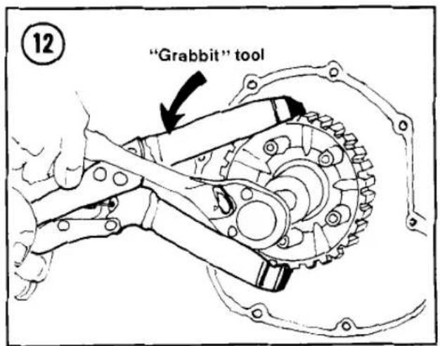
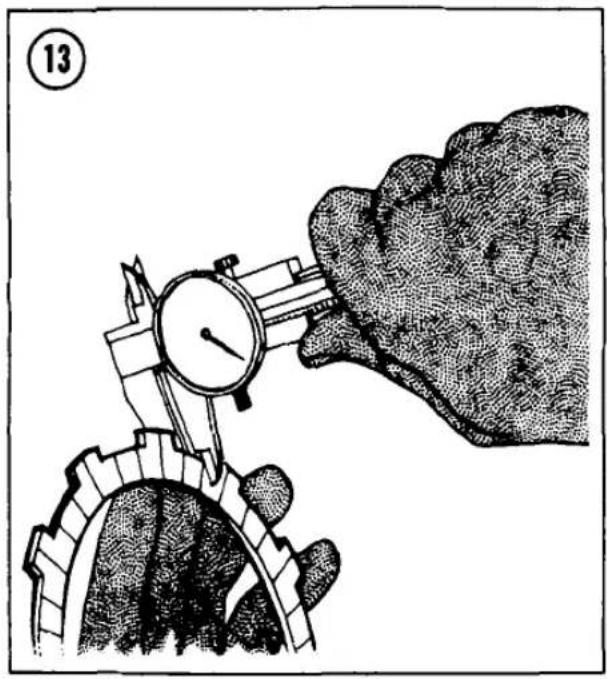


- Visually inspect the outer splines that mount the clutch plates to the inner hub and outer housing. If the splines are chewed up or badly worn, install new parts.
- Inspect the clutch springs. The spring tension must be checked while the spring is compressed in a special spring tester (Figure 16). See Table 1 at the end of this chapter for specifications. Replace all springs if one has sagged below the limit.
- Roll the clutch pushrod on a flat surface to check for bends or damage. Examine the rounded ends of the pushrod for damage. Replace it if bent or damaged.
- Examine the clutch housing and ring gear and check for excessive wear or loose rivets. If
its condition is marginal, replace the housing. Clutch failure at high rpm can cause expensive engine damage.
- Check the clutch shaft bearing (Figure 17), spacers and thrust washers. Replace any parts that are cracked or excessively worn, loose or galled.
- Measure the clutch housing inside diameter (ID) with an inside micrometer or vernier calipers (Figure 18). If the bushing ID is larger than the limit in Table 1, install a new clutch housing.
- Measure the clutch sleeve outside diameter (OD) with a micrometer or vernier


calipers. If the sleeve OD is smaller than the limit in Table 1, install a new clutch sleeve.
Assembly
- See Figure 10. Install the input shaft spacer with the flat side facing out and install the bearing sleeve (Figure 19).
- Install the clutch bearing (Figure 20).
- Install the outer housing and thrust washer (Figure 21).
- Install the inner clutch hub and install the washer (Figure 22).
NOTE
If one side of the spring washer is marked "OUTSIDE," be sure that side faces out.
- Use a new clutch hub locknut when possible and torque it as specified in Table 2 (Figure 23).
NOTE
To install the clutch hub nut, you must hold the clutch hub (which is mounted on the transmission input shaft) steady. You can lock the input shaft by stuffing a clean rag or a copper penny between the secondary shaft gear and clutch ring gear tooth or by using a special tool, such as the "Grabbit," available from Joe Bolger Products, Inc., Summer Street, Barre, MA 01005.
- Install the clutch release pushrod through the center of the transmission input shaft.


- Apply molybdenum disulfide grease to the steel ball and the end of the pressure plate pusher. Install them in the end of the input shaft (Figure 24).
- Install the clutch plates (Figure 25). The sequence is friction plate, metal plate, friction plate, etc., starting and ending with a friction plate. Take care to align the plate tabs carefully with the housing teeth.
NOTE
If you are installing new dry plates, first wet them with oil to prevent clutch seizure.
- Install the pressure plate, aligning its splines with the clutch hub splines. Install the 5 springs and bolts (Figure 26). Tighten the bolts gradually in a crisscross pattern.

- Install the cover screws and tighten them by hand. Note the ignition timing lead clamps at the front and rear bottom cover screws (Figure 27).
NOTE
When installing cover screws, check that each one sticks up the same amount before you screw them all in. If not, you've got a short screw in a long hole and vice versa. Do not use an impact driver to install cover screws; they'll be too tight.
- Add engine oil and adjust the clutch release and cable play as described in Chapter Three.
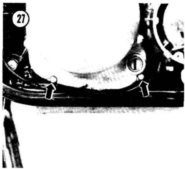
Table 1 CLUTCH WEAR LIMITS
| Clutch housing ID | 1.458 in. (37.03 mm) |
| Clutch sleeve OD | 1.258 in. (31.96 mm) |
| Disc tab/housing clearance | |
| Standard | 0.014-0.026 in. (0.35-0.65 mm) |
| Limit | 0.028 in. (0.7 mm) |
| Friction disc thickness | 0.11 in. (2.7 mm) |
| Disc/plate warp | 0.016 in. (0.4 mm) |
| Housing/secondary gear backlash | |
| KZ500 | 0.005 in. (0.13 mm) |
| KZ550 | 0.0055 in. (0.14 mm) |
| Spring tension | 41 lb. @ 0.93 in. (18.5 kg @ 23.5 mm) |
NOTE: If you own a 1982 or later model, first check the Supplement at the back of the book for any new service information.
CHAPTER SIX
TRANSMISSION
This chapter covers all the parts that transmit power from the clutch to the drive chain: the engine sprocket, the transmission gears, the shift drum and forks that slide the gears and the shift linkage that turns the shift drum.
The shift linkage can be repaired while the engine is mounted in the frame, but repair of the transmission gears, shift drum and shift forks requires engine removal and crankcase separation as described in Chapter Four.
Table 1 at the end of the chapter lists transmission wear limit specifications. Many inspection measurements require a precision inside and outside micrometer, dial gauge or the equivalent. If you don't have the right tools, have your dealer or machine shop take the required measurements.
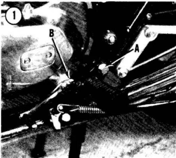
SPROCKET COVER
The clutch release mechanism is mounted on the inside of the sprocket cover. The sprocket cover and shift linkage cover underneath it must be removed for access to the shift linkage.
Removal/Installation
- Remove the left footpeg bolt, lockwasher and the footpeg (A, Figure 1).
- Remove the shift pedal (B, Figure 1); remove the bolt and spread the slot open with a screwdriver if necessary. If your bike has linkage between the shift pedal and shift shaft, remove the circlip at the pedal and remove all the linkage (Figure 2).
- Remove the 2 bolts securing the starter motor cover and remove the cover and gasket (Figure 3).
- Remove the 4 bolts securing the engine sprocket cover and remove the cover (Figure 4). Be careful not to damage the shift shaft oil seal.


- To install the sprocket cover, reverse the removal steps. Note the following:
a. Make sure the 2 sprocket cover dowel pins are in place (Figure 5).
b. Align the shift pedal with the top of the footpeg.
NEUTRAL SWITCH
The neutral indicator light is activated by a switch mounted in the shift linkage cover, under the sprocket cover (Figure 6). The switch is turned on when the shift drum end plate is at its NEUTRAL position (Figure 7). The insulated switch pin that rides against the end plate is then grounded against the metal portion of the plate, completing the indicator light circuit.
ENGINE SPROCKET
The engine sprocket is on the left-hand end of the transmission output shaft, behind the sprocket cover. The drive chain is endless—it has no master link. To remove the drive chain, remove the engine sprocket from the output shaft and remove the swing arm; see Swing Arm Removal in Chapter Ten.
Removal
- Remove the engine sprocket cover as described in this chapter.
- Remove the 2 sprocket retainer bolts (Figure 8) and remove the retainer.
- Slide the sprocket off the output shaft.
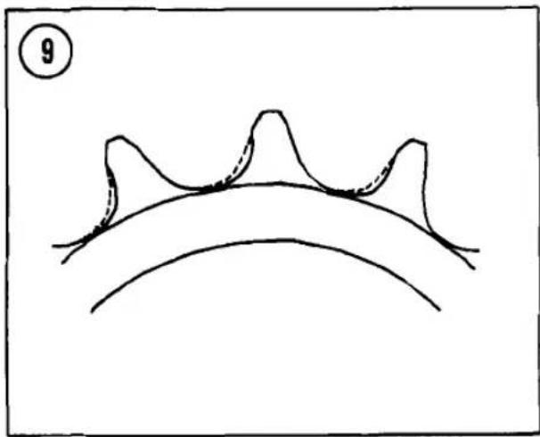
NOTE
You may have to loosen the drive chain to allow sprocket removal. See Drive Chain Adjustment in Chapter Three.
Installation
- Inspect the engine sprocket for wear. If the teeth are undercut as shown in Figure 9, install
a new sprocket; a worn sprocket will quickly wear out a new drive chain. - Position the drive chain on the sprocket, then slide the sprocket onto the output shaft.
- Install the sprocket retainer and the 2 bolts. Torque the bolts as specified in Table 2.
- Install the sprocket cover as described in this chapter.
- Adjust drive chain play if it was loosened. See Drive Chain Adjustment in Chapter Three.
SHIFT LINKAGE
Refer to Figure 10. The shift linkage can be repaired without separating the crankcases, but removal of the shift drum and forks requires engine removal and crankcase separation.
Inside the transmission, gears are moved by shift forks, which are moved from side to side by the camming slots in the cylindrical shift drum. The linkage (outside the engine cases) that converts up-and-down motions of the gearshift pedal into rotation of the shift drum is the gear shift mechanism.
The shift pedal is mounted on one end of the shift shaft. At the other end of the shaft are a shift arm and an overshift limiter under the arm. The shift arm pawls rest against pegs in the end of the shift drum. When the shift shaft
10
SHIFT LINKAGE AND DRUM

- Circlip
- Needle bearing
- Screw
- Pin plate
- Ratchet pins
- Shift drum
- Cotter pin
- Shift fork
- Dowel pin
- Detent cam
- Dowel pin
- Circlip
-
Guide bolt
-
Lockplate
- Detent bolt
- Spring
- Detent plunger
- Circlip
- Shift rod
- Shift fork
- Shift fork
- Shift linkage
- Link spring
- Return spring
- Return spring pin


is rotated, the pawls grasp the pegs and rotate the shift drum. The overshift limiter hooks keep the shift drum from moving more than one gear at a time.
The 2 legs of the strong hairpin return spring on the shift shaft rest against a stationary centering pin. When the shift pedal is released, the return spring brings the shift shaft back to its center position.
Removal
- Remove the engine sprocket cover as described in this chapter.
- Remove the engine sprocket as described in this chapter.
- Place a drain pan under the shift linkage cover and remove the neutral indicator lead (Figure 6).
- Remove the 7 screws (Figure 11), then remove the shift linkage cover and gasket. Tap the cover loose with a soft mallet, if necessary. Use care; the cover is positioned with dowel pins.
- Note carefully how the shift link pawls engage the shift drum. Move the shift linkage arms out of engagement with the shift drum (Figure 12) and pull the shift linkage out of the crankcase.
CAUTION
Do not pull the shift fork rod (A, Figure 13) out. If it is pulled out 2 in. (50 mm), the shift forks within the crankcase will fall off the rod. This would require removal and disassembly of the engine to reposition the forks.
- To expose the pegs on the shifter drum, remove the screw from the cover plate (B, Figure 13) and remove the plate.
Inspection
- Inspect the seals in the shift linkage cover (Figure 14). Replace any damaged seals; heat the cover in an oven to about 212°F and tap the old seals out. Install new seals flush with the surface of the cover, with their numbered side out.
- If the transmission fails to shift gears, check for a weak pawl spring; bent, worn or binding

14
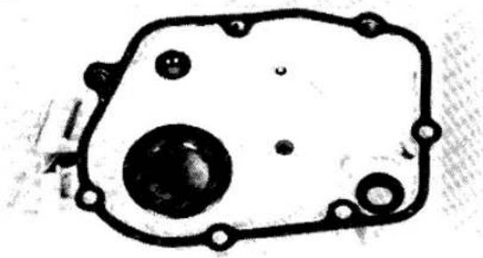
16

15


pawls; worn shift drum pins; a broken return spring; or a broken return spring pin.
- If the transmission undershifts or overshifts, check for a binding, bent or worn detent; a weak detent spring; bent or worn pawls; worn shift drum pins; a loose return spring pin; or a bent or weak return spring.
- If the transmission jumps out of gear, check for a binding, bent or worn detent or a weak detent spring.
- Replace any other broken, bent, binding or worn parts, including shift drum pins.
Installation
CAUTION
Use a locking agent such as Loctite Lock N' Seal on all shift linkage screws. Loose linkage will cause serious engine damage.
- Check that the shift drum ratchet pins are in good condition. If the pins are removed, install
the long pin (which times the NEUTRAL light) as shown in relation to the hole on the end of the drum (Figure 15). Secure the pin plate screw with a locking agent such as Loctite Lock N' Seal.
2. Check that the shift shaft return spring pin is tight (C, Figure 13). If loose, remove it, apply a locking agent such as Loctite Lock N' Seal, and tighten it securely.
3. Be sure the return spring and link springs are in place on the shift linkage (Figure 16), then spread the shift linkage pawls as you install the linkage in the crankcase, mating the pawls to the shift drum.
4. Make sure the return spring is positioned correctly on the pin (A, Figure 17).
5. Check that the linkage cover dowel pins are in place (B, Figure 17) and install the cover and gasket. Install the 7 screws (Figure 11). The middle front screw has a wiring clamp under it.


- Install the neutral indicator lead (Figure 6).
- Install the engine sprocket as described in this chapter.
- Install the engine sprocket cover as described in this chapter.
SHIFT DETENT
The shift drum has a cam on the end opposite the pins and linkage. A spring-loaded detent is mounted inside the oil pan, riding on the face of the shift drum cam (Figure 18). The detent locks the shift drum in position after a shift has been made, to help keep the transmission from jumping out of gear.
Remove and inspect the detent assembly whenever the transmission will not stay in gear or if it is very hard to shift. To remove the detent assembly, remove the oil pan as described in Oil Pump Removal in Chapter Four. Remove the shift drum detent bolt, spring and pin (Figure 19).
Check that the plunger slides freely inside the bolt. Measure the free length of the detent spring (Figure 20). If the spring is shorter than the limit in Table 1, install a new spring.
Install the shift drum detent pin, spring and bolt and install the oil pan as described in Oil Pump Installation in Chapter Four.
TRANSMISSION
Repair of the transmission gears, shift drum and shift forks requires engine removal and case separation. If the transmission fails to shift properly or jumps out of gear, check the condition of the shift linkage before splitting the engine cases. See Shift Linkage Inspection and Shift Detent in this chapter.
Transmission Operation
The basic transmission has 6 pairs of constantly meshed gears on the input and output shafts. Each pair of meshed gears gives one gear ratio. In each pair, one of the gears is locked to its shaft and always turns with it. The other gear is not locked to its shaft and can spin freely on it. Next to each free spinning gear is a third gear which is splined to the same shaft, always turning with it. This third gear can slide from side to side along the shaft splines. The side of the sliding gear and the free spinning

21
SHIFT LINKAGE AND DRUM

- Circlip
- Needle bearing
- Screw
- Pin plate
- Ratchet pins
- Shift drum
- Cotter pin
- Shift fork
- Dowel pin
- Detent cam
- Dowel pin
- Circlip
-
Guide bolt
-
Lockplate
- Detent bolt
- Spring
- Detent piunger
- Circlip
- Shift rod
- Shift fork
- Shift fork
- Shift linkage
- Link spring
- Return spring
- Return spring pin

gear have mating "dogs" and "slots." When the sliding gear moves up against the free spinning gear, the 2 gears are locked together by the dogs and slots, locking the free spinning gear to its shaft. Since both meshed input and output gears are now locked to their shafts, power is transmitted from one shaft to the other at that gear ratio.
Neutral "Finder"
In 5th gear there are 3 steel balls on the output shaft spaced 120° apart, which help keep the transmission from overshooting to 2nd gear when the rider wants to shift from 1st to NEUTRAL when the bike is stopped. As long as the bike is moving and the output shaft is turning, the balls are thrown away from the shaft and will allow upshifting to 2nd. When the bike stops, the ball on top falls into a groove in the shaft and keeps the gear from sliding into position for higher gears.
Shift Drum And Fork Operation
Each sliding gear has a deep groove machined around its outside. The curved shift fork arm rides in this groove, controlling the side-to-side sliding of the gear and therefore the selection of different gear ratios.
Each shift fork slides back and forth on a guide shaft or on the shift drum and has a peg that rides in a groove on the face of the shift drum. When the shift linkage rotates the shift drum, the zigzag grooves move the shift forks and sliding gears back and forth.

A spring-loaded detent plunger rides in a cam on the end of the shift drum. This detent helps keep the drum in the selected gear or in NEUTRAL.
SHIFT DRUM AND FORKS
Removal
Refer to Figure 21.
- Remove the engine from the motorcycle and separate the crankcase halves as described in Chapter Four.
- In the lower engine case, pull out the shift fork rod and remove the 2 smaller shift forks.
- Turn the engine case upside down. Flatten the lockplate and unscrew the shift drum guide bolt (A, Figure 22).
- Remove the shift drum detent bolt, spring and plunger (B, Figure 22).
- On the clutch end of the shift drum, remove the detent cam circlip and the cam (Figure 23).
- Remove the large shift fork cotter pin and guide pin (Figure 24).
- Pull the shift drum out of the engine case, taking off the third shift fork as you go.
Inspection
- Inspect each shift fork for wear on the fork arms (Figure 25) and for signs of burning or cracking. See Table 1 for the minimum shift fork thickness specification.
- Make sure the forks slide smoothly on their shaft and check that the shaft is not bent.
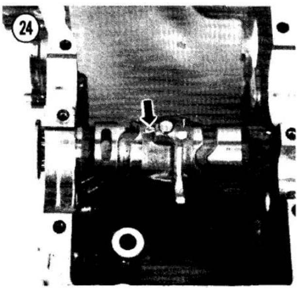

25
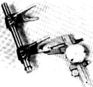

26
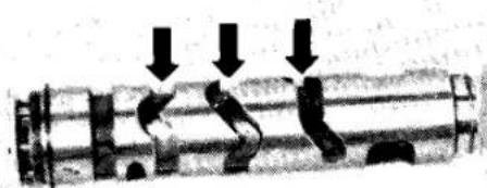
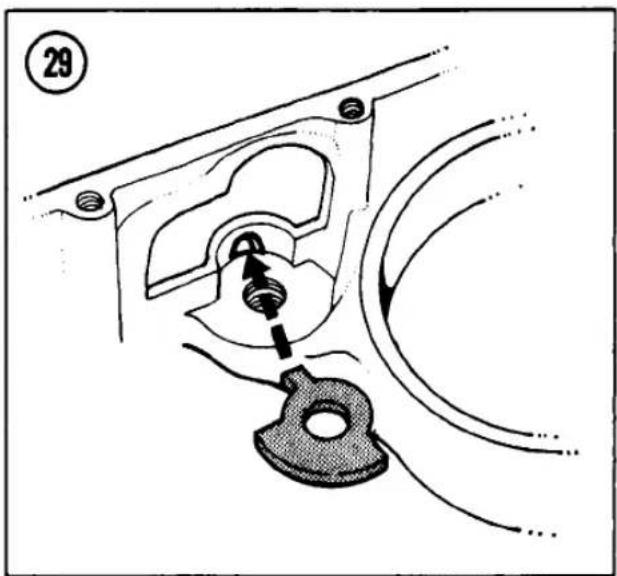


- Check the grooves in the shift drum for wear, chipping or roughness (Figure 26). The fork pegs should fit in the drum grooves without excessive play. The maximum shift drum groove width and minimum shift fork guide pin diameter are specified in Table 1.
- Measure the free length of the detent spring (Figure 20). Install a new spring if shorter than the limit in Table 1.
- Inspect the detent cam for wear. Replace it if visibly worn.
- Check that the shift drum ratchet pins are in good condition. If the pins are removed, install the long pin as shown in relation to the hole on the end of the drum (Figure 15). Secure the pin plate screw with a locking agent such as Loctite Lock N' Seal.
Installation
Refer to Figure 21.
- Apply molybdenum disulfide grease to any new parts. Oil all parts before assembly.
- Push the shift drum into the engine case. Position the large shift fork so that the drum will enter the long end of the fork boss first (Figure 27).
- Check that the detent cam dowel pin is in place (Figure 28). Install the detent cam and circlip. Use a new circlip when possible; an old clip may have lost its tension during removal.
-
Install a new lockplate and the shift drum guide bolt. The lockplate tab must seat in the crankcase hole (Figure 29). Fold up a side of the lockplate.
-
Rotate the shift drum to the NEUTRAL position (Figure 30) and install the detent plunger, spring and bolt.
- Install the large shift fork guide pin with a new cotter pin as shown (Figure 24). The guide pin fits in the middle shift drum groove.
- Install the 2 smaller shift forks and the shift rod, fitting the fork pegs into the shift drum grooves (Figure 31).
NOTE The 2 smaller shift forks are identical.
TRANSMISSION GEARS
Removal/Disassembly
Refer to Figure 32.
- Remove the engine from the motorcycle and separate the crankcase halves as described in Chapter Four.
- Carefully lift out the input and output shaft gear clusters. Carefully note the location of any thrust washers or bearings on the ends of the shafts.
- To disassemble the transmission shafts, remove the circlips with circlip pliers. Carefully lay out all the clips, washers and gears in the order you remove them.
NOTE
To remove the output shaft 5th gear, hold the shaft vertically by the 3rd gear, spin the shaft and lift off 5th gear (Figure 33). Do not lose the 3 "neutral finder" balls. In case you do, they are 5/32 in. diameter.
32
TRANSMISSION


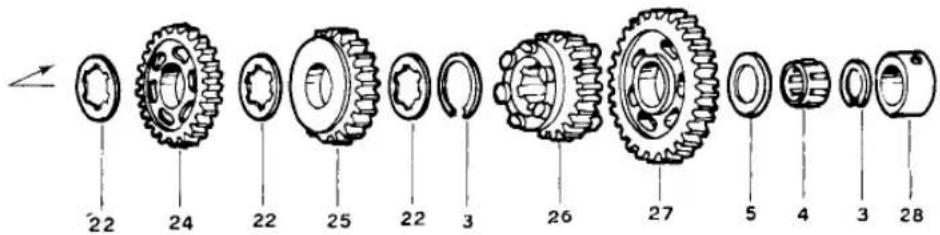
- O-ring (clutch pushrod)
- Bearing race
- Circlip
- Needle bearing
- Thrust washer
- Input 2nd gear
- Toothed washer
- Input 6th gear
- Bushing
- Input shaft
- Input 3rd/4th gear
- Thrust washer
- Input 5th gear
-
Ball bearing
-
Bolt (2)
- Sprocket retainer
- Engine sprocket
- Spacer
- Output shaft
- Neutral balls (3), 5/32 in.
- Output 2nd gear
- Splined washer
- Output 6th gear
- Output 4th gear
- Output 3rd gear
- Output 5th gear
- Output 1st gear
- Bearing race
33

Inspection
- Inspect the transmission shaft bearings or bushings. Check for roughness, noise or excessive play. To replace a bearing, use a gear puller or heat the shaft in an oven to about 212°F and tap the old bearing off.
- Check each gear for missing teeth, chips and excessive wear of the shift fork grooves. See Table 1 for the maximum gear groove width specification.
NOTE
When one gear is replaced, inspect the mating gear on the opposite shaft very closely. Any damage is likely to affect both gears.
34
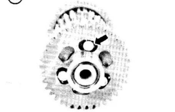
- Check that the mating gear dogs and slots (Figure 34) are in good condition. Worn dogs and slots can cause the transmission to jump out of gear.
- Check that the gears slide smoothly on the shaft splines.
Assembly/Installation
Refer to Figure 32.
- Note the following during gear set assembly:
a. Apply molybdenum disulfide grease to any new parts. Oil all parts before assembly.
b. Use new circlips when possible. Old clips may have lost their tension during removal.
c. When installing circlips on splined shafts, position them so that their opening falls on top of a spline groove and does not align with a splined washer tooth (Figure 35).
- The assembly sequence for the input shaft (Figure 36) is 5th gear (flat side toward the machined-in 1st gear), washer, circlip, 3rd/4th gear (3rd gear toward 5th gear), circlip, splined washer, bushing (chamfered side toward 3rd/4th gear), 6th gear (dogs toward 4th gear), splined washer, circlip, 2nd gear (recessed side toward 6th gear), washer, needle bearing, circlip, needle bearing outer race (with O-ring inside).


36
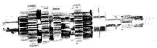
NOTE
When installing the input shaft copper bushing, align its oil hole with that of the shaft (Figure 37).
- The assembly sequence for the output shaft (Figure 38) is 2nd gear (flat side toward bearing), washer, circlip, 6th gear (dogs toward 2nd gear), circlip, splined washer, bushing (chamfered side toward 6th gear), 4th gear (recessed side toward 6th gear), washer, 3rd gear (flat side toward 4th gear), washer, circlip, 5th gear (grooved side toward 3rd gear), 1st gear (flat side away from 5th gear), washer, needle bearing, circlip, outer race.
NOTE
When installing the output shaft 5th gear, do not grease the steel balls to hold them in place. These balls must be able to move freely. Insert the balls in the holes with a smaller outer diameter (Figure 39), not in the large diameter set of holes.
- Install the gear sets in the upper crankcase half, meshing the shift fork fingers with the gear grooves (Figure 40). Rotate the bearings until the dowel pins seat and make sure the alignment rings are fully seated in the bearing and case grooves.
37

38

39


Table 1 TRANSMISSION WEAR LIMITS
| Gear backlash | 0.010 in. (0.25 mm) |
| Gear fork groove width | 0.207 in. (5.25 mm) |
| Gear/shaft or bushing clearance | 0.006 in. (0.16 mm) |
| Shaft journal OD | 0.786 in. (19.96 mm) |
| Shaft bearing race ID | 1.025 in. (26.04 mm) |
| Shift fork finger thickness | 0.185 in. (4.7 mm) |
| Shift fork pin diameter | |
| Shift rod forks | 0.309 in. (7.85 mm) |
| Shift drum fork | 0.312 in. (7.93 mm) |
| Shift drum groove width | 0.325 in. (8.25 mm) |
| Shift drum detent spring length | 1.21 in. (30.7 mm) |
NOTE: If you own a 1982 or later model, first check the Supplement at the back of the book for any new service information.
CHAPTER SEVEN
FUEL AND EXHAUST SYSTEMS
This chapter includes removal and repair procedures for the carburetor, fuel tank, fuel tap, air suction system and exhaust system. See Chapter Three for routine idle speed and throttle cable adjustment. Detailed carburetor specifications are given in Table 1 at the end of this chapter.
The following paragraphs explain the basic operation of carburetors, which may be helpful in troubleshooting a problem you suspect is caused by carburetion. If you are disassembling a carburetor, go on to Carburetor Service later in this chapter.
The throttle slide carburetor uses a cable-controlled sliding throttle valve that carries the jet needle (Figure 1). The manufacturer is Teikei.
Float Mechanism
To assure a steady supply of fuel, the carburetor is equipped with a float valve through which fuel flows by gravity from the gas tank into the float bowl.
Inside the bowl is a pair of floats which move up and down with the fuel level. Resting on the
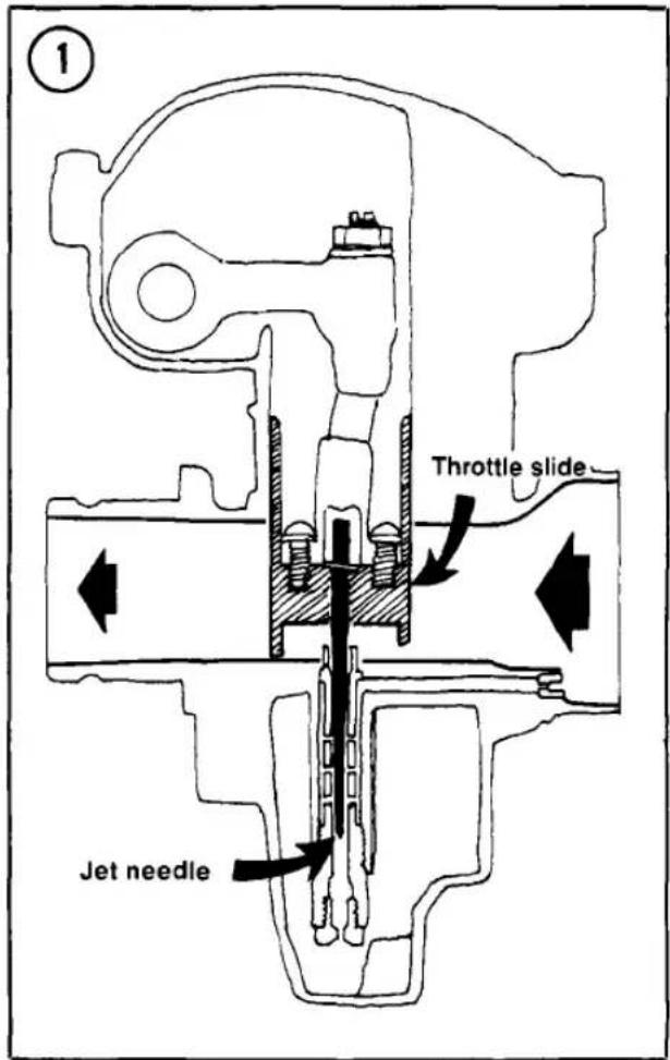
float arm is a float needle, which rides inside the float valve. As the float rises, the float needle rises inside the float valve and blocks it, so that when the fuel has reached the required level in the float bowl, no more can enter.
Pilot and Main Fuel Systems
The carburetor's purpose is to supply and atomize fuel and mix it in correct proportions with air that is drawn in through the air intake. At primary throttle openings (from idle to 1/8 throttle), a small amount of fuel is siphoned through the pilot jet by suction from the incoming air. As the throttle is opened further, the airstream begins to siphon fuel through the main jet and needle jet. The tapered needle increases the effective flow capacity of the needle jet as the needle rises with the slide, because it occupies less of the needle jet's area.
In addition, the amount of cutaway in the leading edge of the throttle slide aids in controlling the fuel/air mixture during partial throttle openings.
At full throttle, the carburetor venturi is fully open and the needle is lifted far enough to permit the main jet to flow at full capacity.
Choke System
The choke system consists of a sliding choke valve and a vacuum relief plate on the choke valve. When the choke valve closes the carburetor opening it causes a very high vacuum in the carburetor bore. Fuel flows from all jets and mixes with air coming through the relief plate opening to provide a rich mixture for cold starting.
CARBURETOR TROUBLESHOOTING
If the bike stalls or bogs down under hard acceleration, check the fuel level as described in this chapter.
If the mixture is too lean at any or all throttle settings, the engine may overheat. It may generate brown exhaust smoke. It may stutter at high rpm. The performance (acceleration and top speed) will fall off. You may be able to confirm this by checking the spark plugs. If the mixture is too lean across the rpm scale, the spark plugs will be white and their electrodes may be rounded. While riding the motorcycle, use the choke to see if the performance improves with what would normally be an overrich mixture.
If the mixture is too rich at any or all throttle settings, the engine may be sluggish and blubbery. It may generate black exhaust smoke. It may perform best while still cold. If the mixture is too rich across the rpm scale, the spark plugs may be black and sooty. Take out the air cleaner element and ride the motorcycle to see if the performance improves with what would normally be too lean a mixture. If it does, the mixture is too rich. Reinstall the air filter element immediately to prevent engine damage from dust and dirt.
Diagnosing the Problem
The fact that the mixture being burned is too rich or too lean does not necessarily indicate that the carburetion is at fault. The motorcycle may as easily have an ignition or compression problem.
If the mixture is wrong all up and down the rpm range, check the obvious fuel system components. For example, if the mixture is too rich, check for a clogged air cleaner element or too high a fuel level in the float bowl. If the mixture is too lean, check the fuel tap strainer and the fuel lines for blockage, check for too low a fuel level and check for an air leak at the rubber carburetor holders.
Before taking apart the carburetors, you should first check out the spark plugs, ignition timing and cylinder compression.
Miscellaneous Carburetor Problems
Water in the carburetor float bowl and a sticking slide needle can result from careless washing of the motorcycle. To remedy the problem, remove and clean the carburetor bowl, main jet and any other affected parts. Be sure to cover the air intake when washing the machine.
Be sure that the carburetor mounting clamps are tight.
If gasoline leaks past the float bowl gasket, high-speed fuel starvation may occur. Varnish deposits on the outside of the float bowl are evidence of this condition.

Dirt in the fuel may lodge in the float valve and cause an overrich mixture. As a temporary measure, tap the carburetor lightly to dislodge the dirt. Clean the fuel tank, fuel tap, fuel line and carburetor at the first opportunity should this occur.
REJETTING
NOTE
This book covers U.S. models subject to emission control laws. These laws subject motorcycle dealers and their employees to heavy fines for modifying emissions related components. Although Federal law does not cover modification by the motorcycle owner, some states have laws that prohibit emission-related modifications by owners. Check the laws in your area before you change carburetor parts.
Do not try to solve a problem by rejecting if all the following conditions hold true.
a. The engine has held a good tune in the past with standard jetting and needle position or number.
b. The engine has not been modified.
c. The engine is being operated at the same altitude, climate and average speeds as in the past.
Rejetting the carburetors may be required if any of the following conditions hold true.
a. A nonstandard air filter element is being used.
b. A nonstandard exhaust system is being used.
c. Any of the top end parts (piston, camshaft, compression ratio, etc.) have been modified.
d. The motorcycle is in use at considerably higher or lower altitudes or in a markedly hotter or colder or wetter or drier climate than in the past.
e. The motorcycle is being operated at considerably higher speeds than before and changing to colder spark plugs does not solve the problem.
f. Someone has changed the jetting or the needle position or number on your motorcycle.
g. The motorcycle has never held a satisfactory engine tune.
The original jets and jet needle numbers are listed in Table 1 at the end of this chapter.
CARBURETOR TUNING
The following parts of the carburetor can be changed to alter the fuel mixture. Each part has the most effect over a narrow range of throttle openings, but each also has a lesser effect over a broader range of throttle openings.
Pilot Jet and Screw
The pilot jet and idle mixture setting affect mixture from 0 to about 1/8 throttle. As pilot jet numbers increase, the fuel mixture gets richer. As the idle mixture screw is opened (turned out), the mixture gets leaner.
On motorcycles sold in the U.S., the idle mixture screw is sealed under a plug.
Throttle Slide
The throttle slide cutaway (Figure 2) affects airflow at small throttle openings. Cutaway sizes are numbered and larger numbers result in a leaner mixture.
Jet Needle
The jet needle affects the mixture from 1/2 to 3/4 throttle. The grooves at the top of the jet needle permit adjustment of the mixture ratio. As the clip is raised (and the needle drops


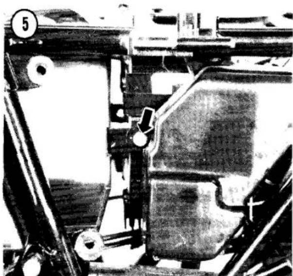
deeper into the jet), the mixture gets leaner (Figure 3); as the clip is put in a lower groove the mixture gets richer.
On models imported into the U.S. there is only one fixed needle position. The only alteration possible is through substitution of a different needle number or by raising the needle by putting a washer under it (as the needle is raised the mixture gets richer).
Needle Jet
The needle jet works in conjunction with the jet needle. Only one size needle jet is available for KZ500/550 motorcycles.
Main Jet
The main jet controls the mixture at full throttle and has some effect at lesser throttle openings. Each main jet is stamped with a number. Larger numbers provide a richer mixture, smaller numbers a leaner mixture.
CARBURETOR SERVICE
There is no set rule regarding frequency of carburetor overhaul. A motorcycle used strictly for street riding may go 30,000 miles or more without needing a carburetor overhaul. Operation in dusty areas or poor air cleaner maintenance may shorten the useful life of the carburetor. See Table 1 at the end of this chapter for carburetor specifications.
Removal/Installation
Remove all 4 carburetors as an assembled unit. Replacement of an individual carburetor is described in this chapter under Separation.
- Put the bike up on its centerstand.
- Remove the fuel tank as described in this chapter.
- Remove the side panels from the motorcycle and loosen the air cleaner housing mounting bolts on both sides (Figure 4 and Figure 5).
- Loosen the locknuts and shorten the throttle cable adjusters at the handgrip and at the carburetors for maximum cable free play.
- Disconnect the closing (front) throttle cable from the pulley and bracket and then disconnect the opening (rear) cable (Figure 6).


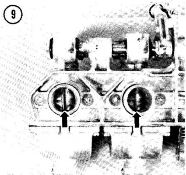


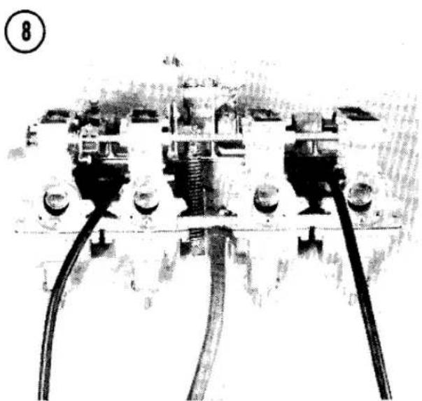


- Disconnect the overflow/drain tubes from the carburetors (A. Figure 7).
- On U.S. models, slide the vacuum hose clamps up (B, Figure 7) and disconnect the hoses from the carburetors.
- Loosen the clamp at the front of each carburetor (C, Figure 7), then roll back the spring (D) at the rear of each carburetor.
- Pull the carburetor assembly back to the rear and remove it from the motorcycle (Figure 8).
- To install, reverse the removal steps. Note the following:
a. If the throttle linkage was disturbed or if a carburetor throttle slide was removed, synchronize the throttle slides visually so that they each have an equal gap at the throttle bore when closed (Figure 9). To do this loosen the adjuster locknuts (A, Figure 10), turn the adjusters as required and tighten the locknuts. Open the throttle fully and check that the bottom of the lowest throttle slide clears the top of the throttle bore; if it does not, loosen the open limit locknut and turn the open limit adjuster as required (B, Figure 10). Tighten the locknut.
b. On U.S. models, check that the vacuum lines are attached at the rubber carburetor holders (Figure 11).
c. Make sure the carburetors are fully seated forward in the rubber carburetor holders. You should feel a solid "bottoming out"
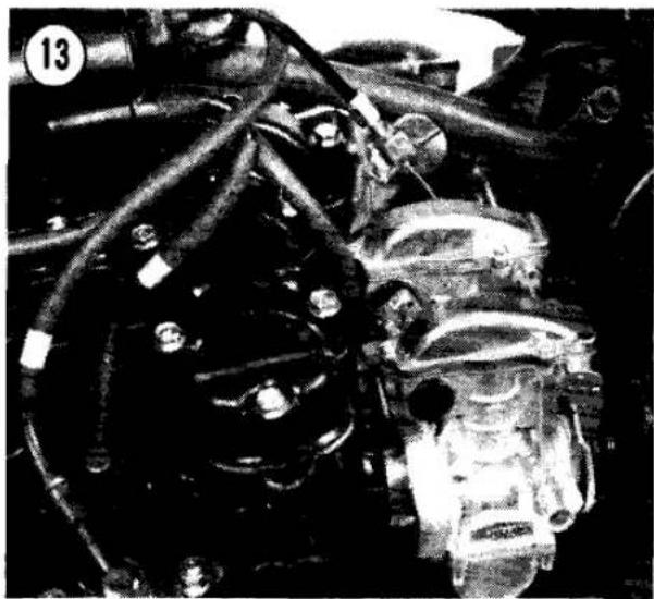
when they're correctly installed. Tighten the mounting clamps securely.
CAUTION
Make sure the carburetor mounts are air tight. Air leaks can cause severe engine damage because of a lean mixture or the intake of dirt.
d. Tighten the air cleaner housing mounting bolts after the carburetors have been installed.
e. Route the closing (rear) throttle cable along the left-hand side of the frame backbone and the opening cable (front) along the right-hand side. Hook up the opening cable first, then the closing (rear). The cables must not be twisted, kinked or pinched.
f. Route the 4 overflow/drain tubes through the rubber strap at the rear of the engine (Figure 12).
f. Route the 2 vent tubes up to the top of the airbox (Figure 13).
g. Adjust the throttle cables and carburetors as described in Chapter Three.
Disassembly/Assembly
Refer to Figure 14 and Figure 15. Most carburetor disassembly can be done without separating an individual carburetor from the assembly.
We recommend disassembling only one carburetor at a time to prevent accidental interchange of parts.

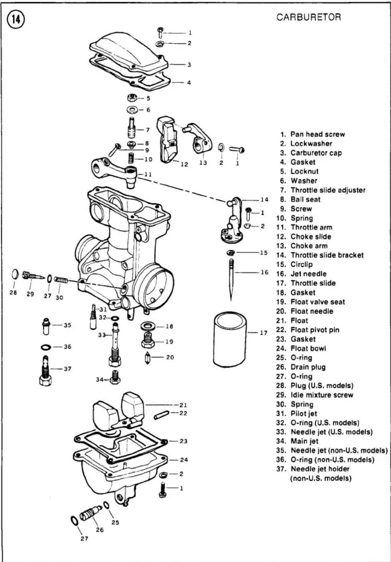
15
CARBURETOR LINKAGE

- Choke detent ball, 5/32 in.
- Spring
- Choke shaft
- Washer
- Spring
- Fast idle cam
- Screw
- Fast idle arm
- Locknut
- Fast idle adjuster
-
Open throttle stop
-
Screw
- Screw
- Cable catch
- Spring
- Close pulley
- Circlip
- Screw
- Throttle shaft
- Set plate
- Lockwasher
-
Open pulley
-
Pivot pin
- Bracket
- Spring
- Idle speed knob
- Pivot
- Fast idle link
- Spring
- Carburetor mounting screw
- Carburetor bracket
- Throttle return spring
- Bracket


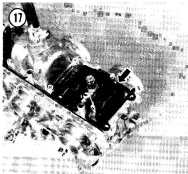


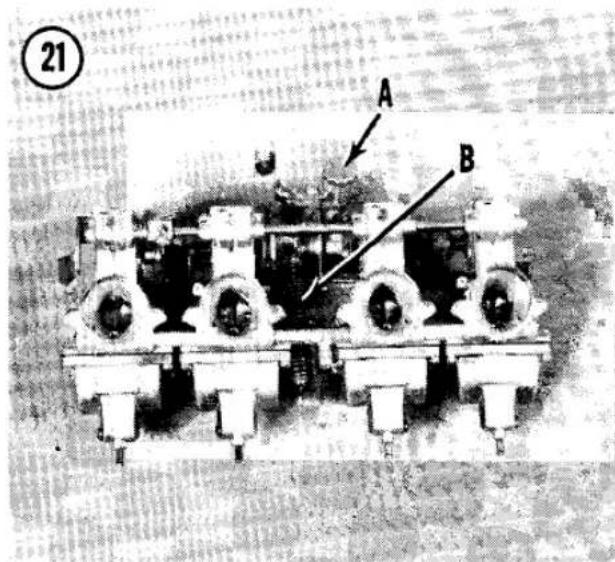

Jet and idle mixture screw removal/installation
- Remove the float bowl screws, lockwashers and the float bowl and gasket (Figure 16).
- Push out the float pivot pin (Figure 17) and remove the float assembly.
- Remove the float needle, float valve and gasket (A. Figure 18).
- Unscrew the main jet (B, Figure 18) and pilot jet (C).
5A. On U.S. models, unscrew the needle jet holder and O-ring (under the main jet). Turn the carburetor upside down or push the needle jet out from the carburetor bore (Figure 19).
5B. On other models, unscrew the needle jet and O-ring (under the main jet). - Remove the idle mixture (air) screw, spring and O-ring.
NOTE
On U.S. models, the idle mixture screw is covered by a plug (Figure 20) bonded in place at the factory. When disassembling the carburetor for overhaul, the plug should be removed in order to clean the passage with compressed air. Before removing the idle mixture screw, count the number of turns it takes to seat it lightly.
- To assemble, reverse this procedure. Note the following:
a. On non-U.S. models, turn the idle mixture screw in until it seats lightly, then back it out the number of turns specified in Table 1.

b. On U.S. models, turn the mixture screw in until it seats lightly, then back it out the same number of turns noted during removal. Install a new plug and seal the edges of the plug lightly with silicone sealant.
c. Tighten the jets securely, but be careful not to strip their threads.
d. Inspect the float bowl gasket and replace it if damaged. If there is much residue in the float bowl, the carburetor body should be cleaned thoroughly.
e. After assembling the carburetor, turn it upside down and listen to hear if the floats are moving freely.
f. Perform Fuel Level Inspection and Idle Mixture Adjustment as described in this chapter.
Throttle slide and jet needle removal/installation
The throttle slide and jet needle can be removed without separating the carburetors.
- Remove the idle adjust knob, washer and spring (A. Figure 21).
- Remove the throttle return spring (B. Figure 21).
- Remove the 3 screws and the carburetor top cover and gasket from each carburetor (Figure 22).
- Remove the throttle arm screws and the fast idle arm screw (Figure 23).
- Remove the throttle pulley mounting screws.
- Remove the throttle shaft retainer between carburetors No. 3 and No. 4 (Figure 24).
- Remove the rubber plugs from both ends of the throttle shaft.
- Push and turn the throttle shaft out of the carburetor bodies.
- Remove the throttle slide and jet needle assemblies (Figure 25).
- Unscrew the 2 slide bracket screws (Figure 26) to expose the jet needle and circlip.
- Remove the needle and retainer from the throttle slide. Note the position of the clip on the needle.
- To install, reverse this procedure. Note the following.
a. Apply a light coat of grease to the throttle shaft before installing it.
b. The nipple on the throttle shaft retainer plate fits into a hole on the carburetor bracket.
c. Synchronize the throttle slides visually so that they each have an equal gap at the throttle bore when closed (Figure 9). To adjust, loosen the adjuster locknuts (A, Figure 10), turn the adjusters as required and tighten the locknuts. Open the throttle fully and check that the bottom of the lowest throttle slide clears the top of the throttle bore; if it does not, loosen the open limit locknut and turn the open limit adjuster as required (B, Figure 10). Tighten the locknut.
Separation
See Figure 15. The carburetors are joined by a common choke valve shaft, throttle slide shaft and a mounting bracket. Almost all carburetor parts can be replaced without separating the carburetors. If you want to clean the carburetors internally, it's best to take them to a Kawasaki dealer for soak cleaning of internal passages. There are many plastic and rubber parts that must be removed before using a caustic carburetor cleaning solution.
Cleaning and Inspection
- Thoroughly clean and dry all parts. If a special carburetor cleaning solution is used, all non-metal parts must be removed (gaskets, O-rings, etc.).

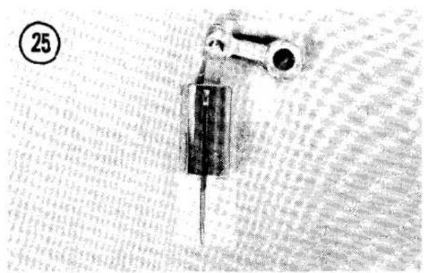
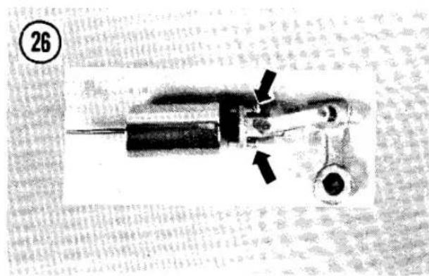


- Blow out all the passages and jets with compressed air. Don't use wire to clean any of the orifices: wire will enlarge or gouge them.
- Check the cone of the float needle and replace it if it is scored or pitted (Figure 27).
- Inspect the throttle slide for scoring and wear. Replace it if necessary.
- Examine the end of the idle air (mixture) screw for grooves or roughness. Replace it if damaged. Replace a worn O-ring.
- Check the O-rings on the float chamber drain plug. Replace them if damaged.
- Check the choke relief plate for smooth operation: push it in and let it spring back (Figure 28). If it does not operate smoothly,
check for dirty or damaged parts; clean or replace as necessary.
FUEL LEVEL INSPECTION
The fuel level in the carburetor float bowl is critical to proper performance. The fuel flow rate from the bowl up to the carburetor bore depends not only on the vacuum in the throttle bore and the size of the jets, but also upon the fuel level. Kawasaki gives a specification of actual fuel level, measured from the top edge of the float bowl with the carburetor held level (Figure 29).
This measurement is more useful than a simple float height measurement because actual fuel level can vary from bike to bike, even when their floats are set at the same height. However, fuel level inspection requires a special clear tube that attaches to the overflow tube (Figure 29). You can get the proper tube at your Kawasaki dealer.
The fuel level is adjusted by bending the float arm tang.
- Block up the front end of the motorcycle so that the carburetor bores are horizontal. The carburetors must be level.
- Pull the carburetor overflow/drain tube up and attach a clear tube to the end. The tube must have an inside diameter not less than 1/4 in. (6 mm) so that capillary action will not draw the fuel up inside, giving a false reading.
- Hold the clear tube against the carburetor body and turn the fuel tap to PRI (prime). With the carburetor level to the ground, check the fuel level in the tube. It should be slightly below the bottom edge of the carburetor body. See Table 1 for your bike's fuel level specification.

NOTE
Take your reading just after the fuel level has risen to its maximum in the tube. If you raise the tube (and the fuel drops in the tube) you'll probably get a faulty level reading. Turn the fuel tap ON, drain the tube and try it again, forcing the fuel level to rise against surface tension within the tube.
- If the fuel level is incorrect, adjust the float height. Remove the float bowl from the
carburetor and bend the float tang (Figure 30) as required to get the right fuel level. Install the float bowl and recheck the fuel level.
NOTE
If you want the fuel level lower (a greater distance below the carburetor body) bend the tang so the floats stick up higher when held upside down.
IDLE MIXTURE ADJUSTMENT (NON-U.S. MODELS)
The idle fuel/air mixture affects low-speed emissions. as well as idling stability and response off idle. On motorcycles imported into the United States, the idle mixture screw is set and sealed at the factory (Figure 20) and requires no adjustment.
For other models, use the following procedure.
- Adjust the idle speed to specification.
- Turn each idle mixture screw in until it seats lightly, then back it out the number of turns specified in Table 1.
CAUTION
Never turn the idle mixture screw in tight. You'll damage the screw or its soft seat in the carburetor.
- Readjust idle speed to specification, if necessary.
- Turn each mixture screw slightly again to see if the idle speed increases. Readjust idle speed, if necessary.
FAST IDLE ADJUSTMENT
Adjustment of the fast idle linkage should rarely be required, but if the engine stalls when the choke is used on a cold engine or if the idle speed is too high when the choke is used, remove the carburetors from the engine and check that there is about 0.07 in. (1.8 mm) clearance between the bottom of the throttle slide and the bottom of the throttle bore when the choke is fully ON.
If the clearance is incorrect, loosen the fast idle adjuster locknut and turn the adjuster as required (Figure 31). Tighten the locknut.


CRANKCASE BREATHER
The crankcase breather separates oil mist droplets from blowby gas and routes the oil back to the crankcase via a drain hole. The vapors are routed to the air cleaner housing. No maintenance is required; but if the oil drain is not kept clear during engine assembly or if the engine is overfilled with oil, oil can be sucked up into the air cleaner housing.
Removal/Installation
-
Disconnect the breather hose (Figure 32) and remove the cover bolt with its O-ring.
-
Remove the cover and O-ring (Figure 33).
- When installing the breather cover, make sure the O-rings are in good condition and make sure the breather cover pin seats behind the pin cast into the crankcase (Figure 34).
AIR SUCTION SYSTEM (U.S. MODELS)
The air suction system (Figure 35) consists of a vacuum switch valve, 2 air suction valves (reed valves) and air and vacuum hoses. This system does not pressurize air, but uses the momentary pressure differentials generated by

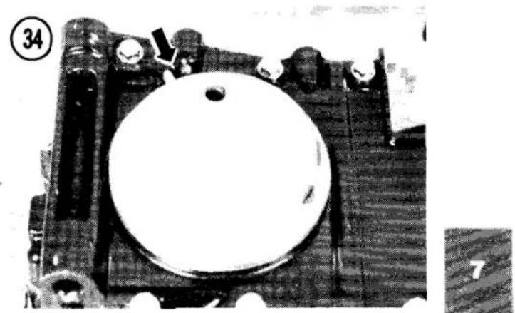
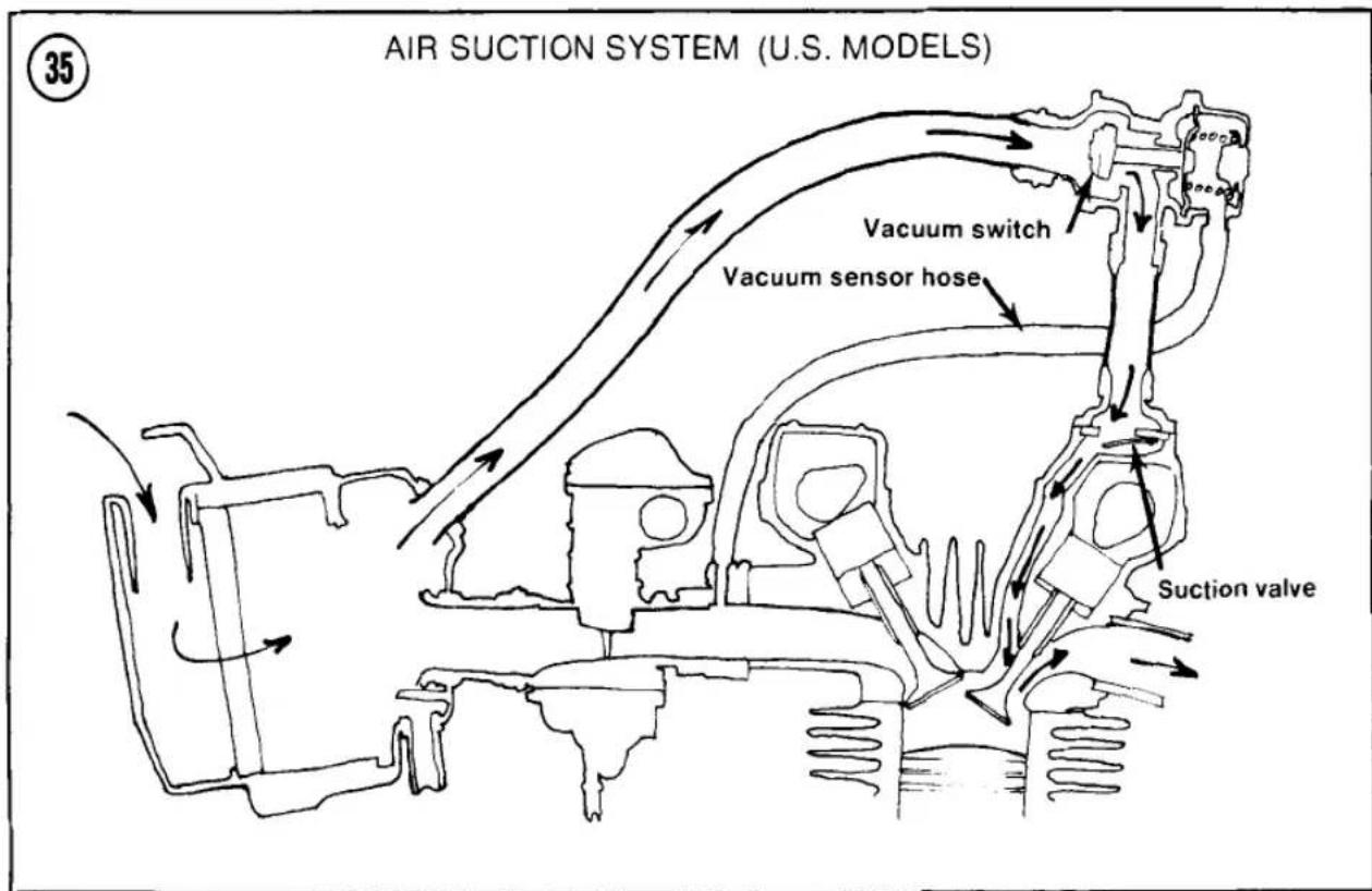
the exhaust gas pulses to introduce fresh air into the exhaust ports.
The vacuum switch (Figure 36) normally allows fresh air pulses into the exhaust ports but shuts off air flow during engine braking. This helps prevent backfiring in the exhaust system due to the greater amount of unburned fuel in the exhaust gas during deceleration.
The air suction valves, on top of the valve cover, are basically check valves. They allow the fresh air to enter the exhaust port and prevent any air or exhaust from reversing back into the system.
Suction Valve Removal/Installation
If the engine idle is not smooth, if engine power decreases seriously or if there are any abnormal engine noises, remove the air suction valves and inspect them.
WARNING
Some fuel may spill during these procedures. Work in a well-ventilated area at least 50 feet from any sparks or flames, including gas appliance pilot lights. Do not smoke in the area. Keep a BC rated fire extinguisher handy.
- Check that the ignition switch is OFF.
- Remove the fuel tank as described in this chapter.
- Slide up the lower hose clamps and pull the hoses off the air suction valve covers (A. Figure 37). Swing the vacuum switch and air hoses up out of the way.
- Remove the bolts securing the air suction valve covers (Figure 37).
- Remove the covers and pull the valves up out of the valve cover (Figure 38).
- Check the suction valves for cracks, folds, warpage or any other damage (Figure 39).
- Check the sealing lip coating around the perimeter of the assembly. It must be free of grooves, scratches or signs of separation from the metal holder.
NOTE
The valve assembly cannot be repaired. It must be replaced if damaged.
- Wash off any carbon deposits between the reed and the reed contact area with solvent.
36
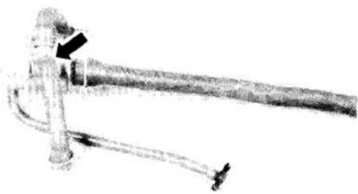


39


CAUTION
Do not scrape deposits off or the assembly will be damaged.
- Install by reversing the removal steps.
Vacuum Switch Test
Inspect the vacuum switch if there is backfiring during deceleration or other abnormal engine noise.
- Run the engine until it is warm.
- Rev the engine to 4,000 rpm and snap the throttle shut. Note the intensity and frequency of any backfiring for comparison later in this test.
- Shut the engine off and, at the air cleaner housing, disconnect and plug the hose from the vacuum switch (Figure 40).
- Start the engine, rev it to 4,000 rpm, snap the throttle shut and compare the backfiring to what you heard before. If the backfiring is the same, there is nothing wrong with the vacuum switch.

- If the backfiring is different, the vacuum switch is faulty. Install a new switch.
FUEL TANK
As water and dirt accumulate in the fuel tank, engine performance will deteriorate. The fuel system should be cleaned when the engine is cold.
WARNING
Some fuel may spill during these procedures. Work in a well-ventilated area at least 50 feet from any sparks or flames, including gas appliance pilot lights. Do not smoke in the area. Keep a BC rated fire extinguisher handy.
Removal/Installation
- Check that the ignition switch is OFF.
- Put the bike up on its centerstand.
- Swing the seat open or remove it.
- Turn the fuel tap ON and disconnect the fuel and vacuum lines at the fuel tap. Lift up the rear of the tank slightly, if necessary.
- On models with fuel level gauges or warning lights, disconnect the fuel level sensor wires.
- Pull the tank up and to the rear and remove it.
- Discard the fuel in the tank. Pour about a pint of clean fuel into the tank, install the cap, slosh the fuel around for about a minute and pour it out into a safe container.
- To install, reverse the removal steps. Note the following.
a. Insert the tank brackets carefully over the frame grommets (Figure 41). Don't pinch any wires or control cables.
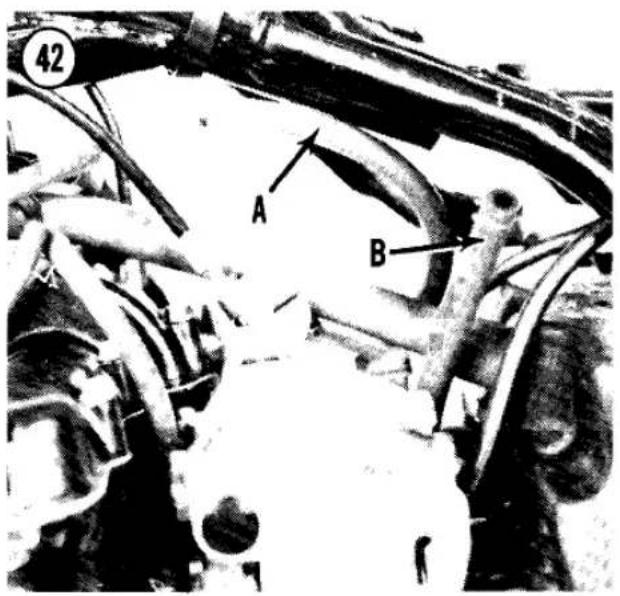

44
FUEL TAP

- O-ring
- Washer (2)
- Bolt
- Screw (2)
- Cover plate
- Wave washer
- Lever
-
Valve gasket
-
Drain plug
- Valve body
- O-ring
- Diaphragm assembly
- Spring
- Diaphragm cover
- Lockwasher (4)
- Screw (4)
45

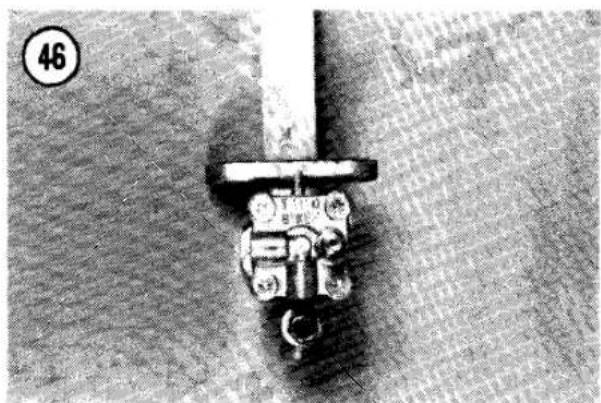

b. The vacuum hose (A, Figure 42) is smaller than the fuel line (B).
c. Partially fill the tank with fresh fuel and check for leaks around the tap and at the fuel line connections.
FUEL TAP
The vacuum-operated fuel tap has no OFF position. The tap should pass no fuel in ON or RES until a running engine provides the vacuum required to operate the diaphragm valve. In PRI (prime) the tap will pass fuel whether the engine is running or not.
Removal/Installation
WARNING
Some fuel may spill during these procedures. Work in a well-ventilated area at least 50 feet from any sparks or flames, including gas appliance pilot lights. Do not smoke in the area. Keep a BC rated fire extinguisher handy.
- Remove the fuel tank.
- Turn the fuel tap to PRI (prime) and drain the fuel into a clean gas can.
- Remove the 2 fuel tap mounting bolts and the tap and O-ring.
- Inspect the fuel tap mounting O-ring and clean the feed tube screen whenever you remove the tap from the tank (Figure 43).
- To install, reverse the removal steps. Note the following:
a. The vacuum hose (A, Figure 42) is smaller than the fuel hose (B).
b. Make sure that fuel does not flow in the ON position when the engine is not running.
c. Check for leakage after you install the fuel tap.
Inspection
See Figure 44. Disassemble the tap and check that the O-ring (Figure 45) and diaphragm are clean and undamaged. Look for pin holes in the diaphragm. Any bit of debris on the valve O-ring will prevent the valve from closing.
Make sure the diaphragm spring is in place. Install the diaphragm cover as shown in Figure 46.
FUEL LEVEL SENDING UNIT
Models with a fuel level gauge or warning light have a sending unit mounted in the bottom of the fuel tank. When installing a sending unit, make sure the mounting O-ring is in good condition. When installing a fuel level gauge sending unit, the arrow on the bottom of the sending unit should point to the front of the tank (Figure 47).

EXHAUST SYSTEM
- Right pipe/muffler
- Nut (8)
- Exhaust pipe holder (4)
- Split collars (8)
- Gasket (4)
- Right footguard
- Lockwasher (6)
- Screw
- No. 3 exhaust pipe
-
Gasket (4)
-
Clamp (4)
- Clamp bolt (4)
- Cross tube
- Left pipe/muffler
- No. 2 exhaust pipe
- Left footguard
- Rubber kickstand damper
- Left muffler bracket
- Nut (4)
- Right muffler bracket


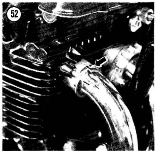

EXHAUST SYSTEM
The exhaust system requires no maintenance other than to make sure the connecting clamps are tight.
Removal/Installation
- See Figure 48. Loosen the crossover pipe clamps (Figure 49).
- Remove the rear footpeg mounting bolts (Figure 50).
-
Remove the exhaust pipe holder nuts (Figure 51) and pry the holders free from the studs.
-
Pull the exhaust pipe and muffler assemblies out of the cylinder head and remove the split collars (Figure 52).
- To separate the exhaust pipe from the muffler, loosen the clamp bolt and twist the muffler off of the pipe.
- To install, reverse the removal steps. Note the following:
a. Make sure the gaskets at the pipe/muffler joint and at the crossover pipe are in good condition.
b. Use new gaskets in the cylinder head exhaust ports (Figure 53).
c. Do not mix up the No. 2 (left) and No. 3 (right) exhaust pipes. Each has an identifying number stamped near the end.
d. Hold the exhaust pipe keepers in place with tape while you assemble the system.
e. Tighten the exhaust pipe holder nuts at the cylinder head first, gradually and evenly. Then tighten the rear footpeg bolts and the clamp bolts.
f. After the job is complete, run the motor and check for leakage. Tighten the clamps again after the engine has cooled down.
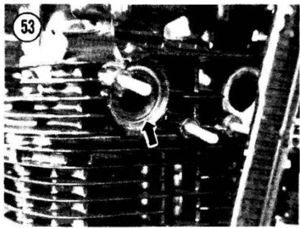
Table 1 CARBURETOR SPECIFICATIONS
| KZ500 | KZ550A, CU.S. | KZ550A, B, COthers | KZ550DU.S. | |
| Item | ||||
| Carburetor | ||||
| size/type | K22P-2A | K22P-2C | K22P-2D | K22P-2E |
| Main jet | No. 90 | No. 92 | No. 92 | No. 94 |
| Pilot jet | No. 32 | No. 32 | No. 32 | No. 32 |
| Jet needle | 4C91-2 | 4D92 | 4D93-2 | 4D92 |
| Throttle slide cutaway | 2.5 | 2.5 | 2.5 | 2.5 |
| Idle mixture screw (turns out) | 1 1/8 | 1 3/8 | ||
| Fuel level | 3.5 mm | 3.5 mm | 3.5 mm | 3.5 mm |

CHAPTER EIGHT
ELECTRICAL SYSTEMS
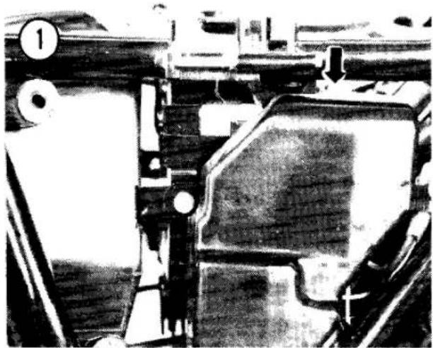

The electrical system includes the battery, ignition system, charging system, electric starter, lighting, horn and gauges or sensors on some models. Table 1 (bulb specifications) is at the end of the chapter.
WIRING DIAGRAMS
Wiring diagrams are located at the end of this book.
FUSES
There are 3 main fuses in a fuse box under the left side cover. Remove the electrical cover screw and the cover (Figure 1). Slide the fuse box out and open it (Figure 2). The main fuse is 20A (A, Figure 3) and the headlight and taillight circuit fuses (B) are 10A. Inside the cover are spare fuses; always carry spares.
Some 1981 and later models have 2 additional fuses for electrical accessories. They are in a separate fuse box under the electrical cover or behind the fuel tank (Figure 4). Both accessory fuses are 10A.
Whenever a fuse blows, find out the reason for the failure before replacing the fuse. Usually, the trouble is a short circuit in the wiring. This may be caused by worn-through insulation, a disconnected wire shorting to ground or possibly a wire pinched during assembly or installation of parts.

WARNING
Never substitute metal foil or wire for a fuse. Never use a higher amperage fuse than specified. An overload could result in fire and destruction of the bike.
BATTERY
The bike is equipped with a 12 volt. 12 ampere-hour battery with an electrolyte specific gravity of 1.280 at 68°F when fully charged.
NOTE
In very warm climates an electrolyte with a specific gravity of 1.260 is used. With this electrolyte you should subtract 0.020 from all specified test readings of specific gravity. If you are uncertain of the electrolyte installed in your motorcycle, any local motorcycle dealer should be able to tell from the label of the acid container he uses to initially service batteries.
Battery electrolyte testing and battery charging may be required after long periods (more than a month) of inactivity or when electrical trouble arises.
The battery is the heart of the electrical system. The majority of electrical system troubles can be attributed to neglect of this vital component.
Batteries evaporate more water in warmer climates, but excessive use of water may be an indication that the battery is being overcharged. It is advisable to check the voltage regulator if this situation exists.
WARNING
Study the Safety Precautions before servicing the battery.
Safety Precautions
While working with batteries, use care to avoid spilling or splashing the electrolyte. The electrolyte is a sulfuric acid solution, which can destroy clothing and cause serious chemical burns. If you get any electrolyte on your clothing, body or any other surface, neutralize it immediately with a solution of baking soda and water, then flush with plenty of clean water.

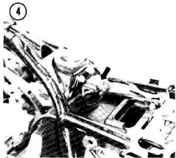
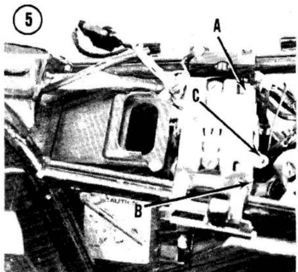

WARNING
Electrolyte splashed into the eyes is extremely dangerous. Wear safety glasses while working with batteries. If electrolyte is splashed into the eye, call a doctor immediately, force the eye open and flood it with cool water for about 5 minutes.
When batteries are being charged, highly explosive hydrogen gas forms in the cells of the battery. Some of this gas escapes through the filler openings and may form an explosive atmosphere around the battery. Sparks, flames or a lighted cigarette can ignite the gas, causing a battery explosion and possible serious personal injury. Follow these precautions to help prevent accidents.
- Do not smoke or permit any flame near a battery being charged or which has been charged recently. Keep the battery away from gas appliances too.
- Do not disconnect or connect live circuits at the battery terminals, because a spark will occur when a live circuit is connected or broken. Turn off the ignition switch first or disconnect the circuit away from the battery. When using a battery charger, don't plug the charger in until the battery clips have been securely attached. Unplug the charger before you remove the clips from the battery.
Removal
Disconnect the negative (-) ground cable first (A, Figure 5), then the positive (+) cable (B). This minimizes the chance of a tool shorting to ground when disconnecting the "hot" positive cable. Remove the battery holder screw and the holder (C, Figure 5).
If the motorcycle will not be used for an extended period, remove the battery from the machine, charge it fully and store it in a cool, dry place. Recharge the battery every 2 months while it is in storage and again before it is put back into service.
Battery Installation
Be very careful when installing the battery to connect it properly. If the battery is installed backward, the electrical system may be damaged.
- Clean the battery terminals, case and tray. Coat the terminals with Vaseline or silicone spray to retard corrosion of the terminals.
- Connect the positive (+) terminal first, then the negative (-) ground. Don't overtighten the clamps.
- Check to make sure the cable terminals won't rub against any metal parts (like the seat). Slide the plastic boot over the positive (+) terminal.
- Connect the battery vent tube and make sure it isn't pinched anywhere. Keep the end away from the mufflers and drive chain. The corrosive gases could cause damage.
Specific Gravity Testing
Hydrometer testing is the best way to check battery condition. Use a hydrometer with numbered graduations from 1.100 to 1.300, rather than one with color-coded bands.
To use the hydrometer, squeeze the rubber ball, insert the tip into the cell and release the ball. Draw enough electrolyte to float the weighted float inside the hydrometer. Note the number in line with the surface of the electrolyte (Figure 6); this is the specific gravity for this cell. Return the electrolyte to the cell from which it came.
The specific gravity of the electrolyte in each battery cell is an excellent indication of that cell's condition. A fully charged cell will read 1.275-1.280, while a cell in good condition reads from 1.225-1.250 and anything below 1.225 is practically dead.
Specific gravity varies with temperature. For each 10° that electrolyte temperature exceeds 80° F, add 0.004 to the reading indicated on the hydrometer. Subtract 0.004 for each 10° below 80° F.
Repeat this measurement for each battery cell. If there is more than 0.050 difference between cells, battery condition is questionable.
If the cells test in the poor range, the battery requires recharging. The hydrometer is useful for checking the progress of the charging operation. Figure 7 shows the approximate state of charge.
It is most important to keep the battery fully charged during cold weather. A fully charged battery freezes at a much lower temperature than one which is partially discharged.
Charging
WARNING
Do not smoke or permit any open flame in any area where batteries are being charged or immediately after charging. Highly explosive hydrogen and oxygen gases are formed during the charging process. Be sure to reread Safety Precautions at the beginning of this section.
CAUTION
Always disconnect the battery cables before connecting charging equipment or you may damage part of the bike's charging system. It is preferable to remove the battery from the motorcycle.
Motorcycle batteries are not designed for high charge or discharge rates. A motorcycle battery should be charged at a rate not exceeding 10 percent of its ampere-hour capacity. That is, do not exceed 0.5 ampere charging rate for a 5 ampere-hour battery or 1.5 amperes for a 15 ampere-hour battery. This charge rate should continue for about 10 hours if the battery is completely discharged or until the specific gravity of each cell is up to 1.260-1.280, corrected for temperature.
Some temperature rise is normal as a battery is being charged. Do not allow the electrolyte temperature to exceed 110° F. Should the temperature reach that figure, discontinue charging until the battery cools, then resume charging at a lower rate.
- Remove the battery from the motorcycle or disconnect the negative (-) ground cable, then the positive (+) cable.
- Before you switch on or plug in the charger, connect the positive charger lead to the positive battery terminal and the negative charger lead to the negative battery terminal.
- Remove all vent caps from the battery, set the charger at 12 volts and switch it on. If the output of the charger is variable, it is best to

select a setting that doesn't exceed 10% of the battery's ampere-hour capacity.
-
When you want to check the state of charge, turn the charger off (or unplug it), disconnect the leads and check the specific gravity. It should be within the limits specified in Figure 7. If it is, and remains stable for one hour, the battery is charged.
-
Install the battery. Connect the positive (+) cable first, then the negative (-) ground.
IGNITION SYSTEM
Breaker Point Ignition Operation
Figure 8 is a schematic diagram of the ignition circuit used on all models with contact breaker point ignition.
The ignition system is equipped with 2 coils and 2 sets of points, each of which fires 2 spark plugs (wired in series) simultaneously. One of the spark plugs in the pair is fired (harmlessly) on the exhaust stroke.
Ignition takes place every 180° of crankshaft rotation; each set of points opens every 360° of crankshaft rotation. The firing order is 1-2-4-3. The left set of points fires cylinders No. 1 and 4; the right set of points fires cylinders No. 2 and 3.
Because the ignition coil fires through 2 spark plugs wired in series, if one of the plugs fails to fire, so will the other. If one plug develops a weak spark, so will the other.
When the breaker points are closed, current flows from the battery through the primary winding of the ignition coil, building a magnetic field around the coil. The breaker cam rotates and is adjusted so that the breaker points open as the piston reaches the firing position ("F" mark on the advancer plate).
![graph TD A["Ignition coil"] --> B["Spark plug"] B --> C["Contact breaker"] C --> D["Condenser"] D --> E["Bat."] E --> F["Breaker Point IGNITION SYSTEM"] F --> G["Switch"] G --> H["Ground"]](/content/2026/06/1280271/images/0bda3c81b42d1bf292db14261eec24b99f6fe5c3b1c843446cd0ac684b68a7fc.jpg)

As the points open, the magnetic field collapses. When this occurs, a very high voltage (up to about 15,000 volts) is induced in the secondary winding of the ignition coil. This high voltage is sufficient to jump the gap at the spark plug, causing the plug to fire.
The condenser assists the coil in developing high voltage and also serves to protect the points. Inductance of the ignition coil primary winding tends to keep a surge of current flowing through the circuit even after the points have started to open. The condenser stores this surge and thus prevents arcing at the points.
Transistorized Ignition Operation
The ignition system consists of 4 spark plugs, 2 ignition coils, an IC igniter unit and 2 timing pickup units. Figure 9 is a diagram of the transistorized ignition circuit for 2 cylinders. The Kawasaki transistorized ignition system is similar to a contact breaker point ignition system. It works much the same, with these differences:
a. Mechanical contact points are replaced by magnetic triggering pickup coils. The elimination of contact breaker points
means that periodic adjustment of point gap and ignition timing are no longer required. Once set properly, initial timing should not require adjustment for the life of the motorcycle.
b. An intermediate electronic switch, the battery-powered IC igniter, receives the weak signals from the pickup coils and uses them to turn the ignition coil primary current on and off.
c. The ignition coil has a special low resistance primary winding that helps it produce a powerful spark at high rpm.
d. The transistorized ignition system's dwell angle increases slightly as engine speed increases. This is a characteristic of the magnetic pickup coils.
e. Ignition timing is not adjustable.
The ignition coil primary current is normally off until the ignition timing rotor cam approaches the pickup coil. As the rotor cam approaches the pickup coil, a pickup coil signal builds to a level that turns the IC igniter on, allowing primary current to flow through the ignition coil. As the rotor cam passes the pickup coil, the trigger signal reverses polarity
![graph TD A["Battery"] --> B["Fuse"] B --> C["Ignition switch"] C --> D["Engine kill switch"] D --> E["Ignition coil"] E --> F["Spark plug"] E --> G["Spark plug"] E --> H["IC igniter"] H --> I["Pick-up coil and timing rotor"]](/content/2026/06/1280271/images/6fcfc10be316672a258f2b7791df1b50baeb62ec590607b25c2c38be84ef5957.jpg)
and turns the IC igniter off. The sudden stoppage of current through the ignition coil primary winding causes the magnetic field to collapse. When this occurs, a very high voltage (up to about 20,000 volts) is induced in the secondary winding of the ignition coil. This high voltage is sufficient to jump the gap at the spark plug, causing the plug to fire.
CONTACT BREAKER POINTS AND CONDENSER SERVICE
See Contact Breaker Points in Chapter Three for point and condenser inspection, adjustment, and replacement.
SPARK PLUGS
See Spark Plugs in Chapter Three for regular inspection and adjustment of spark plugs.
A resistor-type spark plug cap is used on U.S. models to reduce radio interference (Figure 10). If you have a high-speed misfire, check the resistance between the plug terminal and the plug wire spike. Normal resistance is about 10,000 ohms. If resistance is more than 20,000 ohms, the cap is faulty and should be replaced.
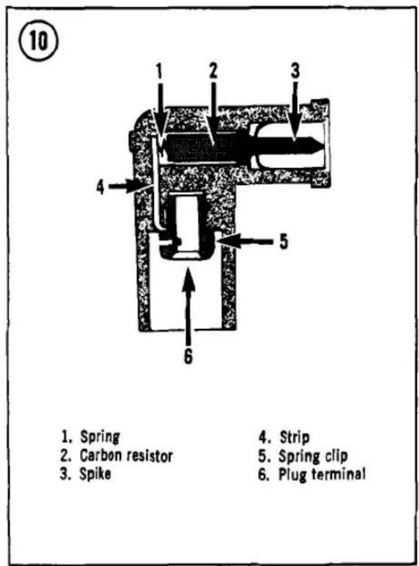
Troubleshooting
If you suspect that 2 of the spark plugs are failing to fire or are delivering weak sparks. check them as follows:
-
Remove the spark plugs from the engine and compare them to the spark plug chart in Chapter Two.
-
If visual inspection shows that one or both of the spark plugs are defective, discard them and install new ones.
-
Check both spark plugs (whether new or used) by putting on their spark plug wires and taping them to the cylinder head fins, so that metal touches metal.
-
Wheel the motorcycle over to a dark corner. Turn on the ignition, operate the starter and observe the sparks. If the plugs throw sparks that are intermittent, feeble or orange-yellow in color and that do not make snapping sounds when they jump, the sparks are weak.
-
If one or both of the spark plugs throwing weak sparks are old, fit new plugs to the spark plug wires and observe the sparks again. Watch also for arcing outside the spark plug cap.
-
If the used spark plugs fail to fire or generate weak sparks and if the new spark plugs throw strong sparks (bluish in color, accompanied by a snapping sound), then one or both of the old spark plugs are defective.
IGNITION ADVANCE MECHANISM
The ignition advance mechanism advances the ignition (fires the spark plugs sooner) as engine speed increases. If it does not advance smoothly, the ignition timing will be incorrect at high engine rpm. The advancer must be lubricated periodically to make certain it operates freely.
Disassembly/Lubrication/Assembly
The ignition advance mechanism is bolted to the right-hand end of the crankshaft, under the timing cover.
-
Remove the 2 timing cover screws and the cover and gasket (Figure 11).
-
Remove the 3 timing plate screws and the plate (Figure 12).

- Hold the larger nut and remove the advancer mounting bolt, large nut and the advancer (Figure 13).
- To remove the cam from the advancer body, hold the base steady, turn the advancer cam until the arms come out of the cam, then pull the cam off its pivot.
- Remove the weight C-clips, washers, weights and washers.
- Install by reversing the removal steps. Note the following:
a. Grease the groove inside the rotor or cam (Figure 14), the weight pivots and the weight arms that fit into the rotor or cam.
b. On transistorized models, when assembling the advancer unit align the the rotor peak and "TEC" mark (Figure 15).
c. On breaker point models, when assembling the advancer unit align the cam mark and the hole in the advancer plate (Figure 16).
d. Check for free movement and full weight return by the advancer springs.
e. When installing the advancer assembly, align the notch in the back of the advancer with the pin in the crankshaft (Figure 17).
f. Advancer bolt torque is 18 ft.-lb. (2.5 Mkg.).
g. Contact point models: Adjust the ignition timing; see Ignition Timing in Chapter Three.
IGNITION COIL
An ignition coil can fail in any of 3 ways. It can develop an open circuit (broken wire) in the primary windings or the secondary windings, in which case the coil won't function at all, or it can develop a partial short circuit, arcing to bridge some of the secondary windings. If that happens, the coil will generate weak sparks at the electrodes of the spark plug.
Removal/Installation
- Check that the ignition switch is OFF.
- Remove the fuel tank; see Fuel Tank Removal in Chapter Seven.
- Disconnect the spark plug leads.


14

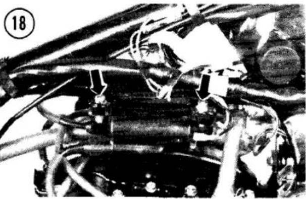
15

19
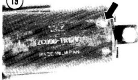

- Disconnect the leads to the ignition coils, then remove the coil mounting nuts and the coils (Figure 18).
- Install by reversing these steps. Note the following:
a. The green wire goes to the left coil and the black wire goes to the right coil. The yellow/red wires go to either the negative (-) or the positive (+) coil terminal (Figure 19).

NOTE
Since the spark fires through one spark plug to ground, and back up through the other spark plug, ignition coil polarity has no effect on performance.
b. U.S. models: Make sure that none of the air induction system hoses or clamps contact the coil wires or terminals.
Testing
-
If the coil condition is doubtful, there are several checks which can be made. Disconnect the coil wires before testing. Measure coil primary resistance, using an ohmmeter set at Rx1. The resistance should be about 4 ohms on contact point models and about 1 1/2 ohms on transistorized models.
-
Measure coil secondary resistance; remove the resistor-type plug caps from the leads and measure between the secondary leads. The resistance should be about 13,000 ohms when the coil is cold (at room temperature).
- Measure the resistance between the coil primary yellow/red wire and ground (coil core) and between the coil secondary lead and ground (coil core). The resistance should be infinite. A low reading indicates a short circuit.
- If a coil does not meet these resistance values, it must be replaced. If the coil exhibits visible damage, it should be replaced.
- If a coil is generating weak sparks, substitute the other coil in the circuit and check the sparks again. If the other coil generates stronger sparks at the electrodes of the spark plugs, there is a short circuit in the secondary windings of the original coil; install a new coil.
PICKUP COILS (TRANSISTORIZED IGNITION)
Inspection
- Remove the right-hand side cover and disconnect the 4-pole pickup coil connector (Figure 20).
- With an ohmmeter set at Rx100, measure the resistance between the 2 pairs of leads: black and blue (No. 1 and 4) and yellow and red (No. 2 and 3). The resistance should be 400-500 ohms.
- Set the ohmmeter at its highest scale and check the resistance between either lead for each pair of cylinders and chassis ground. The reading should be infinite.
- If the pickup coil fails either of these tests, check the wiring to the coil. Replace the coil if the wiring is okay.
Removal/Installation
The pickup coils are under the timing cover on the right-hand side of the engine.
- Open the right-hand side cover and disconnect the 4-pole pickup coil/IC igniter connector (Figure 20).
- Remove the 2 timing cover screws and the cover and gasket (Figure 11).
- Remove the 3 timing plate screws and the plate (Figure 12).
- To install, reverse these steps.


IC IGNITER (TRANSISTORIZED IGNITION)
The operation of the IC igniter (Figure 21) can be checked simply by removing one of each pair of spark plugs, grounding it against the cylinder head while the plug lead is connected, turning the ignition ON and touching a screwdriver to the pickup coil core (Figure 22). If the IC igniter is good, the plug will spark.
Remember that the IC igniter is battery-powered and will not function if the battery is dead. The following IC igniter test can be made on the motorcycle.
- Remove one of each pair of spark plugs and ground it against the cylinder head while its plug wire is connected.
- Disconnect the 4-pole connector from the pickup coils (Figure 20).
- Turn the ignition ON and connect a positive (+) 12 volt source to the black lead and a negative (-) 12 volt source to the blue lead. As the voltage is connected, the plug should spark.
- Repeat the test for the other pair of plugs, positive (+) to the yellow lead from the IC igniter and negative (-) to the red lead.
- If the IC igniter fails these tests, install a new one. If the IC igniter passes these tests but you still have an ignition problem that can't be traced to any other part of the ignition system, substitute an IC igniter that you know is good
and see if that solves the problem. Some transistorized ignition troubles just won't show up on your workbench.
CHARGING SYSTEM
The charging system consists of the battery, alternator, voltage regulator and rectifier. Figure 23 is a schematic diagram of the 3-phase charging system. The rectifier and regulator are combined in one solid-state unit.
NOTE
Early models have a single phase charging system which functions much the same as the 3-phase system. The single phase system is easily identified by having only 2 leads coming from the alternator, instead of 3.
The alternator generates an alternating current (AC) which the rectifier converts to direct current (DC). The regulator maintains the voltage to the battery and load (lights, ignition, etc.) at a constant voltage, regardless of variations in engine speed and electrical power load.
Testing
Whenever charging system trouble is suspected, make sure the battery is good before going any further. Check the specific gravity as described in this chapter. Battery voltage
![graph TD A["Alternator"] --> B["Regulator/rectifier"] B --> C["Control circuit"] C --> D["Fuse"] D --> E["Ignition switch"] E --> F["Load"] F --> G["Battery"] G --> C style A fill:#f9f,stroke:#333 style B fill:#ccf,stroke:#333 style C fill:#cfc,stroke:#333 style D fill:#fcc,stroke:#333 style E fill:…](/content/2026/06/1280271/images/c1125f8fde790e0c8cb7ca47464f4d4d7b2b90c78d075f236ab32317d6d349f7.jpg)

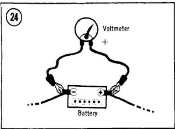
should be above 12 volts. If not, charge the battery. If the battery is okay and all connections are clean and tight, inspect the charging system.
Initial Inspection
-
Start the engine and let it reach normal operating temperature.
-
Connect a 0-20 DC voltmeter to the battery as shown in Figure 24. Bring the engine speed from idle to 4,000 rpm, observing the voltage as you go.
-
Turn the headlight on and off, observing the voltage.
NOTE If your bike doesn't have a headlight switch, disconnect a wire to the headlight or remove and reinstall the headlight fuse.
- The voltage should be at or near battery voltage at idle and it should increase with engine speed, up to about 14.5 volts. If the reading is much higher (more than about 16 volts), the regulator/rectifier is defective and should be replaced. If the reading is less than specified or does not increase with rpm, check the alternator output and resistance and regulator/rectifier resistance.
Alternator Output Test
-
Remove the engine sprocket cover; see Sprocket Cover Removal in Chapter Six.
-
Disconnect the yellow leads from the alternator (Figure 25).
-
On models with 3 yellow leads from the alternator: Start the engine and connect an AC

voltmeter (0-250 volts) to every pair of yellow leads in turn (there are 3 combinations). The meter should read about 75 volts AC. If it is much lower, the alternator is defective. Check stator coil resistance.
- On models with 2 yellow leads from the alternator: Start the engine and connect an AC voltmeter (0-250 volts) to the pair of yellow leads. The meter should read about 50 volts AC. If it is much lower, the alternator is defective. Check stator coil resistance.
Stator Coil Resistance
-
On models with 3 yellow leads from the alternator: With the engine off and an ohmmeter set on a 1 ohm scale, check resistance between every pair of yellow leads in turn (there are 3 combinations). The resistance should be about 0.3-0.5 ohms.
-
On models with 2 yellow leads from the alternator: With the engine off and an ohmmeter set on a 1 ohm scale, check resistance between the yellow leads. The resistance should be about 0.5-0.7 ohms.
-
Set the ohmmeter on the highest scale and check resistance between each yellow lead and ground. Resistance should be infinite.
-
If the stator coil resistance is okay, but alternator output is low, the rotor has probably been demagnetized. Replace the rotor; see Rotor Removal in this chapter.
Regulator/Rectifier Resistance
- Remove the left-hand side cover and open the electrical panel (Figure 1).


ALTERNATOR STATOR
Removal/Installation
The stator is mounted inside the left-hand engine cover.
- Remove the engine sprocket cover; see Sprocket Cover Removal in Chapter Six.
- Disconnect the yellow leads from the alternator (Figure 25).
- Remove the 4 alternator cover screws and the cover and gasket (Figure 27). There are 2 locating dowel pins.
- To remove the stator coils from the cover, remove the 3 coil Allen bolts and the wire guide screws (Figure 28).
- To install, reverse the removal steps. Note the following:
a. Use a locking agent such as Loctite Lock N' Seal on the stator coil Allen bolts.
b. Make sure the 2 cover dowel pins are in place (A, Figure 29).
ALTERNATOR ROTOR
Removal/Installation
The alternator rotor is mounted on the left-hand end of the crankshaft. Rotor replacement is usually necessary only if the rotor magnets have been damaged by mechanical shock or heat. The rotor can be removed after removing the alternator cover/stator.
- Disconnect the white connector and the white/red lead from the regulator (Figure 26).
CAUTION
The white/red lead is "hot." Do not short circuit the voltage regulator when connecting the test leads.
- With an ohmmeter set at Rx10 or Rx100, measure the resistance between each yellow lead and the white/red lead, then between each yellow lead and the black lead. Keep the same meter lead on the white/red and the black leads, in turn. Note the readings.
- Reverse the meter polarity (use the opposite probes to make the connections) and repeat the tests. There should be more than 10 times as much resistance in one direction as in the other. If any 2 leads show the same resistance in both directions, the regulator/rectifier is faulty and should be replaced.
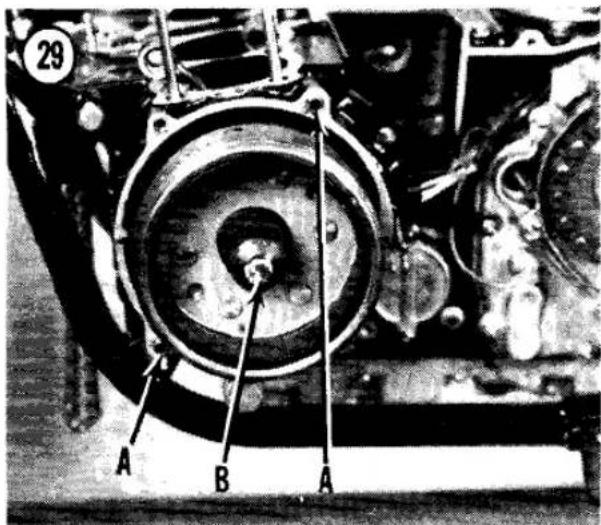
CAUTION
Rotor removal requires a puller such as the one described in the procedure below. Don't pry or hammer on the rotor itself. Damage is sure to result and you may destroy the rotor magnetism.
- Remove the rotor bolt (B, Figure 29).
NOTE
To remove the rotor without a special tool, you can lock the engine by shifting the transmission into gear and stepping on the brake pedal or by removing the clutch cover and stuffing a copper penny or clean rag, folded several times, between the secondary gear and the clutch ring gear.
-
Loosen the rotor. A simple long bolt with 10 mm threads to match the large threaded rotor hole will work. Your Kawasaki dealer has a special tool to do the job. Screw in the bolt to pull the rotor off. You may have to alternate tapping on the puller bolt sharply with a hammer and tightening the bolt some more, but don't hit the rotor.
-
Remove the puller and the rotor.
-
To install, reverse the removal steps. Note the following:
a. Inspect the inside of the rotor carefully for any bits of metal or small parts that may have been picked up by the rotor magnets. Remove them to prevent damage when the engine starts.
b. Use a solvent to clean any oil from the tapered crankshaft end.
![graph TD A["Starter motor"] --> B["Battery"] B --> C["Fuse"] C --> D["Solenoid"] D --> E["Ignition switch"] E --> F["Starter button"] F --> G["Starter lockout switch"] G --> H["Starter motor"] style A fill:#f9f,stroke:#333 style B fill:#ccf,stroke:#333 style C fill:#cfc,stroke:#333 style D fill:#fcc…](/content/2026/06/1280271/images/050ff828a0826b002f28aacbc7398773ab47284e1674b7981751e44d9c1a5181.jpg)
c. Rotor bolt torque is specified in Table 2. Hold the rotor from turning using the same method as during removal.
STARTING SYSTEM
The starting system consists of the starter motor, starter clutch, starter solenoid, starter lockout switch and the starter button. Figure 30 is a schematic diagram of the starting system.
When the clutch lever is pulled and the starter button is pressed, it engages the solenoid switch that closes the circuit. Then electricity flows from the battery to the starter motor.
The starter motor is a 12-volt DC motor geared to the secondary shaft through an idler gear and the clutch gear on the secondary shaft. The starter motor is connected mechanically to the crankshaft and can rotate it when the engine is not running. The starter clutch (between the idler and the clutch gear) uncouples the clutch gear from the secondary shaft when the engine is running.
STARTER MOTOR
Removal/Installation
- Disconnect the battery negative (-) ground lead.

33

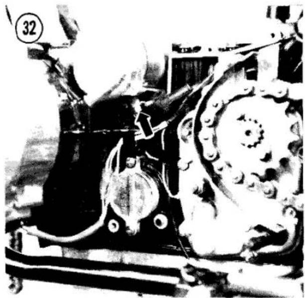
Disassembly/Assembly
The overhaul of a starter motor is best left to an expert. This section shows how to determine if the unit is defective.
- Remove the long starter motor case screws and separate the cases.
NOTE
Write down how many thrust washers are used at each end of the armature and install the same number when reassembling the starter.
- Clean all grease, dirt and carbon dust from the armature, case and end covers.

-
Remove the starter cover and the engine sprocket cover; see Sprocket Cover Removal in Chapter Six.
-
Remove the 2 starter motor mounting bolts (Figure 31).
-
Pull the starter free, pull back the rubber boot and disconnect the starter cable at the motor (Figure 32).
-
To install, reverse the removal steps. Note the following:
a. Make sure the starter case terminal and mounting bosses are clean.
b. Oil the O-ring on the end cap of the motor assembly (Figure 33).
c. Make sure the starter terminal is protected by the rubber cover.
CAUTION
Do not immerse brushes or the wire windings in solvent or the insulation might be damaged. Wipe the windings with a cloth lightly moistened with solvent and dry thoroughly.
-
Measure the length of the brushes (Figure 34). If a brush is worn shorter than 1/4 in. (6 mm), it should be replaced.
-
Inspect the condition of the commutator; the mica in the normal commutator is cut below the copper (Figure 35). A worn commutator is also shown where the copper is worn to the level of the mica. A worn commutator can be undercut, but it requires a specialist. Take the job to your Kawasaki dealer or auto electrical repair shop.
-
Inspect the commutator bars for discoloration. If a pair of bars are discolored, that indicates grounded armature coils.


- Connect the leads of an ohmmeter or test light between pairs of commutator bars (Figure 36); there should be continuity. Connect the test leads between the commutator bars and the shaft (Figure 37); there should be no continuity. If the armature fails either test, it must be replaced.
- Inspect the field coil by checking continuity from the cable terminal to the brush wire. If there is a short or open, the case should be replaced.
- Inspect the front and rear cover bearings for damage. Replace the starter if they are worn or damaged.
- Assemble by reversing the removal steps. Note the following:
a. Check that the 2 case O-rings are in good condition.
b. Align the marks on the case and covers (Figure 33).
STARTER CLUTCH
The starter clutch is mounted on the secondary shaft. inside the crankcase (Figure 38). To remove the starter clutch, see Crankcase Separation in Chapter Four.
The starter motor meshes with an idle gear, which in turn is meshed with the starter clutch on the secondary shaft. The starter clutch gear spins freely in one direction on the secondary shaft.
The starter clutch locks the starter clutch gear to the secondary shaft when the starter

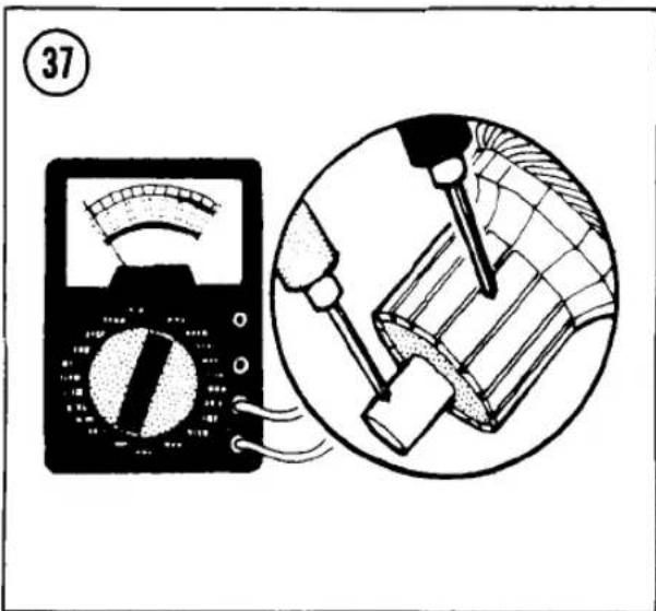

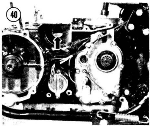
39
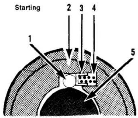

-
Roller
-
Spring
-
Rotor
-
Clutch gear
-
Spring cap
motor is turning the engine by jamming the clutch rollers between the clutch gear and rotor (Figure 39).
After the engine starts, the stationary clutch gear hub rolls the rollers back against their springs and frees the crankshaft from the clutch (Figure 39).
Inspection
To check the operation of the starter motor clutch, remove the starter motor. Try pushing the top of the starter idler gear in both directions by hand (Figure 40). The gear should not turn at all to the rear. It should turn freely and quietly to the front. If the gear fails to operate in this manner, the clutch assembly is malfunctioning.
Disassembly/Assembly
The starter clutch can be disassembled after removing the secondary shaft from the engine; see Crankcase Separation in Chapter Four.
- Remove the 3 rollers, spring caps and springs from the clutch (Figure 41).
- Remove the 3 Allen screws that mount the clutch body to the secondary driven gear.
- When assembling the clutch, use a locking agent such as Loctite Lock N' Seal on the 3 starter clutch Allen bolts.
STARTER SOLENOID
Testing
Before testing the starter solenoid, make sure the battery is fully charged, with adequate

electrolyte, and make sure all the connections between the battery and solenoid are corrosion-free and tight.
Remove the left side cover and electrical cover. The solenoid is below the fuse box (Figure 42).
Turn on the ignition, check that the kill switch is ON (and pull in the clutch lever if your model has a starter lockout) and operate the starter pushbutton. Listen for the loud clicking noise that tells you the solenoid is working.
If the solenoid does not click, check for battery voltage at the black wire to the solenoid when the starter button is pushed. If there is battery voltage but the solenoid doesn't click and all connections are clean and tight, the solenoid is bad and should be replaced. If battery voltage is not available at the black wire, there is an open somewhere in the circuit.
Starter Lockout Switch Replacement
Push up on the bottom of the switch locking tab (Figure 43) and pull out the switch. To install, push the switch in until you feel the tab lock in place.
LIGHTING SYSTEM
Table 1 lists replacement bulbs for the lights and indicators.
If a light stops burning, check first for a burned-out or broken bulb. If bulbs burn out frequently, check for a low level of electrolyte in the battery or for a faulty voltage regulator that could be overcharging the battery.
If the problem is not in the bulb, check the wiring from the socket back to the battery. Measure voltages with the ignition turned ON or resistances with the ignition switch turned OFF and the fuse removed from its holder.
Headlight Adjustment
Adjust the headlight horizontally and vertically according to Department of Motor Vehicle regulations in your area.
Horizontal adjustment
To adjust the headlight horizontally, turn the screw on the lower right side of the headlight
41


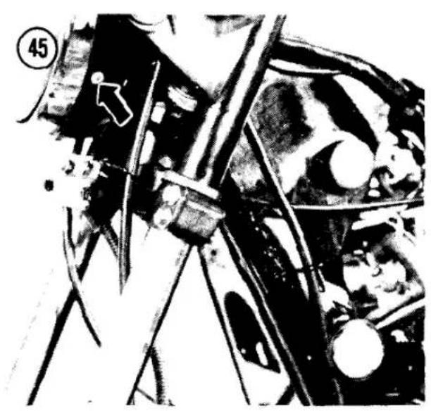

rim (Figure 44). On the KZ550-D, the screw is on the left side of the headlight rim.
NOTE
On models imported into the United Kingdom, there is no horizontal adjustment.
Vertical adjustment
(KZ500, KZ550-A)
For vertical adjustment, just tilt the headlight assembly up or down as required.
NOTE
If the headlight is too tight to move, remove the headlight assembly and loosen the headlight shell mounting nuts.
Vertical adjustment
(KZ550-C, D)
Remove the fairing from the KZ550-D: see Fairing Removal in Chapter Ten. Loosen the bottom positioning bolt under the headlight and tilt the headlight as required. Tighten the positioning bolt. Install the fairing.
NOTE
If the headlight is too tight to move, remove the headlight assembly and loosen the headlight shell mounting nuts.
Headlight Replacement
(Quartz Halogen Models, Except KZ550-D)
- Remove the mounting screw (Figure 45) on each side of the headlight housing.
- Swing the trim bezel and headlight unit out and remove the electrical connector from the backside.
- Remove the dust cover from the back of the light housing, squeeze the spring clip (Figure 46) and remove the lighting element. Install a new element.
CAUTION
Use a clean cloth to grasp the quartz bulb. Don't handle a quartz bulb with your bare fingers or a dirty rag. They'll leave oil on the bulb and will cause it to burn out early.
- Adjust the headlight as described under Headlight Adjustment in this chapter.


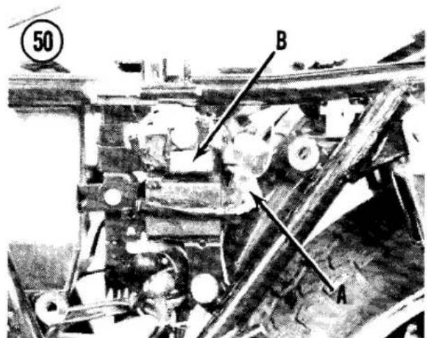
Headlight Replacement (KZ550-D)
- Remove the fairing; see Fairing Removal in Chapter Ten.
- Remove the mounting screw at each bottom corner of the headlight housing.
- Swing the trim bezel and headlight unit out and remove the electrical connector from the backside.
- Remove the dust cover from the back of the light housing, push and turn the bulb stop to the left (counterclockwise) and remove the lighting element. Install a new element.
CAUTION
Use a clean cloth to grasp the quartz bulb. Don't handle a quartz bulb with your bare fingers or a dirty rag. They'll leave oil on the bulb and will cause it to burn out early.
- To assemble, reverse this procedure. Adjust the headlight as described under Headlight Adjustment in this chapter.
Headlight Replacement (Sealed Beam Models)
- Remove the mounting screw (Figure 45) on each side of the headlight housing.
- Pull the trim bezel and headlight unit out and remove the electrical connector from the backside.
- Remove the top and bottom pivot screws (A, Figure 47) and the horizontal adjusting screw (B). Take off the outer rim.
- Remove the 2 screws from the inner rim and remove the sealed beam unit.
- When installing a new sealed beam unit, be sure the "TOP" mark faces up.
![graph TD A["Turn signal switch"] --> B["Blu wht"] A --> C["Wht red"] A --> D["Red wht"] A --> E["Turn signal control unit"] A --> F["Wht grn"] A --> G["Distance sensor"] H["Turn signal lights"] --> I["Blk yel"] J["Turn signal relay"] --> K["Selector switch"] L["Battery"] --> M["-"] N["R"] --> O["Tur…](/content/2026/06/1280271/images/aab7e781f8ac09d507468ff9f48033ef26244a31c34bd3ed1355f458215a3697.jpg)
- Adjust the headlight as described under Headlight Adjustment in this chapter.
Reserve Lighting Unit
Some models are equipped with a reserve lighting system that automatically switches from a burned-out headlight filament to the other filament (high or low beam). At the same time, a warning light will illuminate on the instrument cluster. Always replace the headlight when one filament is burned out.
Replace the reserve lighting unit if it does not function properly (Figure 48).
Front Brake Light
Switch Replacement
Push up on the switch locking tab below the lever bracket (Figure 49) and pull out the switch. To install, push the switch in until you feel the tab lock in place.
Turn Signal Flasher
The turn signal flasher is under the left side cover (A, Figure 50).
Brake Light Failure Switch
The switch that turns on the brake light failure indicator is under the left side cover, under the electrical cover (B, Figure 50). The indicator light should go on when the brake is applied. If the brake light is applied and the brake/taillight bulb is burned out, the indicator light should start flashing.
Some models are equipped with an automatic turn signal cancelling system that turns off the turn signals after 4 seconds have passed and after the bike has traveled 50 meters. Figure 51 is a schematic diagram of the system.
The distance sensor is a switch in the speedometer that opens and closes as the front wheel turns. The turn signal control unit counts 4 seconds after you push the turn signal switch ON, then it counts the number of front wheel revolutions detected by the distance sensor. After both time and distance conditions have

been met. the turn signal control unit energizes a solenoid in the turn signal switch body that pushes the switch OFF.
Troubleshooting
-
In case of trouble with the system, check all wiring and connectors first.
-
If the wiring is okay, check the distance sensor:
a. Remove the headlight, disconnect the 4-pin connector from the speedometer and connect an ohmmeter to the red and light green leads from the speedometer.
b. Disconnect the speedometer cable at its lower end and turn the inner cable by hand.
c. If the distance sensor is working properly, the ohmmeter should show the sensor making and breaking continuity 4 times per revolution: if not, install a new speedometer.
d. Reconnect the 4-pin connector.
- If the distance sensor is okay, check the solenoid in the turn signal switch body:
a. Remove the fuel tank; see Fuel Tank Removal in Chapter Seven.
b. Disconnect the 9-pin connector from the turn signal switch. Push the turn signal switch ON.
c. Momentarily apply a positive (+) 12 volt signal to the white/green lead from the switch, using a wire connected to the positive (+) battery terminal.
d. If the solenoid is okay, it will push the switch OFF; if not, install a new turn signal switch.
e. Reconnect the 9-pin connector.
-
If the solenoid is okay, open the turn signal switch at the handlebar and clean the switch contacts. No replacement parts are available.
-
If cleaning the switch contacts doesn't solve the problem, check the turn signal control unit:
a. Open the turn signal switch at the handlebar.
b. Set a voltmeter at 25 volts DC and connect the positive (+) probe to the white/green solenoid terminal (not the grounded side of the solenoid). Connect the negative (-) probe to the grounded side of the solenoid.

c. With the ignition switch ON and the turn signal selector set at "A" (automatic), push the turn signal switch ON.
d. Raise the front wheel and spin it at least 30 revolutions.
e. If the turn signal control unit is okay, the voltmeter will show battery voltage as the control unit trys to energize the solenoid; if not, replace the turn signal control unit.
FUEL LEVEL SENSOR
Some models have a low fuel level sensor and warning light that illuminates when there is less than about 1/5 of a tank of fuel remaining. The system uses the same bulb as the brake light failure indicator. The sensor is mounted in the fuel tank. If the warning light does not illuminate correctly, replace the sensor; see Fuel Level Sensor in Chapter Seven.
FUEL GAUGE
Some models have a fuel gauge that indicates the amount of fuel in the tank. The sending unit is a variable resistor and float mounted in the fuel tank.
Gauge Inspection
-
Remove the fuel tank; see Fuel Tank Removal in Chapter Seven.
-
Disconnect the 2-pole sending unit coupler.
-
Turn the ignition switch ON. The gauge should read "E."
-
Short the black/yellow and white/yellow leads from the gauge together. The gauge should read "F."
-
If these readings are correct, but the gauge indicates an erroneous fuel level during normal operation, the sending unit is probably bad.
Sending Unit Inspection
- Remove the fuel tank; see Fuel Tank Removal in Chapter Seven.
- Drain all fuel into a safe container.
- Remove the sending unit mounting bolts and the sending unit.
- Check that the float arm moves up and down smoothly throughout its range.
- Measure the resistance of the sending unit with an ohmmeter. At the "full" position, resistance should be 1-5 ohms. At the "empty" position, resistance should be 103-117 ohms. If resistance does not vary smoothly as the arm is moved, the sending unit is faulty.
HORN
The horn can not be disassembled, but it can be adjusted if prolonged use causes a change in the pitch of the sound. An ammeter (0-5 amps) is required during adjustment to prevent misadjustment and excessive current draw.
Disconnect the black lead at the horn and connect an ammeter between the horn and the lead with the positive (+) probe to the horn and the negative (-) probe to the black lead. Loosen the adjusting screw locknut (Figure 52) and turn the adjuster as required, while keeping the horn current under 2.0-3.0 amps. Tighten the locknut.
CAUTION
Don't turn the adjuster in (clockwise) too far or the battery drain will be excessive and the horn may burn out.

Table 1 LIGHT BULB SPECIFICATIONS
| Item | Watts (all bulbs are 12 volt) |
| Headlight | |
| KZ500 1979-1980 | Semi-sealed 45/40W |
| KZ550 1980 U.S. | Sealed beam 50/35W |
| KZ550 1980 Europe | Semi-sealed 45/40W |
| KZ500/550 1981 | Quartz halogen 60/55W |
| Tail/brakelights | |
| U.S., Canada | 8/27W |
| Europe, Australia | 5/21W |
| Turn signals | |
| U.S., Canada, Australia | 23W |
| Europe | 21W |
| Turn signal/running light (front) | |
| U.S., Canada | 23/8W |
| Meters and indicators | 3.4W |
| City light (Europe) | 4W |
NOTE: If you own a 1982 or later model, first check the Supplement at the back of the book for any new service information.
CHAPTER NINE
WHEELS, TIRES AND BRAKES
This chapter describes disassembly and repair of the front and rear wheels, hubs, tires and brakes.
Wear limits and torque specifications are given in Tables 1-5 at the end of the chapter.
WHEELS
All models covered in this book are equipped with cast aluminum alloy wheels.
Rim Runout
Wheel rim runout is the amount of "wobble" a wheel shows as it rotates. If the wheel has been subjected to a heavy impact or if you have any cause to suspect the wheel doesn't run "true," inspect the wheel runout.
-
Remove the tire from the wheel rim so that it doesn't distort the rim; see Tire Removal in this chapter.
-
Support the wheel on its axle and measure the axial and radial runout with a dial indicator (Figure 1).
-
The maximum allowable wheel rim runout on cast wheels is:
a. Axial (side-to-side): 0.02 in. (0.5 mm)
b. Radial (up-and-down): 0.03 in. (0.8 mm)

If the runout exceeds these limits, check the condition of the wheel bearings and install new ones if worn.
- Cast wheels cannot be straightened; they must be replaced if warped or damaged.
CAUTION
Do not attempt to straighten a cast wheel. The wheels may crack if a force strong enough to bend them is applied.
Balance
An unbalanced wheel can be unsafe. Balance weights applied to the light side of the wheel will correct imbalance. Before attempting to balance a wheel, detach the drive chain (rear wheel) and check to make sure that the wheel bearings are in good condition and properly lubricated and that the brake does not drag and keep the wheel from turning freely.


Support the motorcycle with the wheel off the ground. Spin the wheel and allow it to come to rest by itself. Mark the part of the wheel at the bottom and spin it again. If it does not come to rest at the same position, the balance of the wheel may already be acceptable. If you're unsure, spin it and check it again. If the wheel comes to rest at the same position, imbalance is indicated. In this case, add a weight to the top of the wheel and spin the wheel to check the effect.
NOTE
Kawasaki offers weights that can be crimped on the aluminum rims (Figure 2). You may have to let some air out of the tire to install this type of weight. "Tape-A-Weight" or similar adhesive weights are available at motorcycle or auto supply stores. These kits contain test weights and strips of adhesive-backed weights that can be cut to the desired length and attached directly to the rim.
Begin with the lightest weight and increase the size as necessary. When the wheel comes to rest at a different point each time that it is spun, consider it balanced. Tightly crimp weights applied to the rim lip so they won't be thrown off.
FRONT WHEEL

Removal/Installation
- Support the motorcycle with the front wheel off the ground.
- Loosen the speedometer cable nut and disconnect the cable at the wheel (A, Figure 3).
- On models with dual front disc brakes, remove one brake caliper's mounting bolts (B, Figure 3) and support the caliper to keep tension off the brake line.
- Remove the axle nut (C, Figure 3), then loosen the pinch nut (Figure 4) and pull out the front axle.
- Remove the wheel and speedometer drive assembly. There is a collar on the right-hand side of the wheel.
CAUTION
Do not set the wheel down on the brake disc surface. It may get warped or scratched.
NOTE
You may want to insert a piece of wood in the brake caliper in place of the disc. If the brake lever is accidentally squeezed the caliper piston could be dislocated, which may require caliper disassembly and brake system bleeding.
- To disassemble the wheel hub, see Figure 5 or Figure 6 and refer to Wheel Bearings and Seals in this chapter. When installing a brake disc, install the disc with the marked side facing
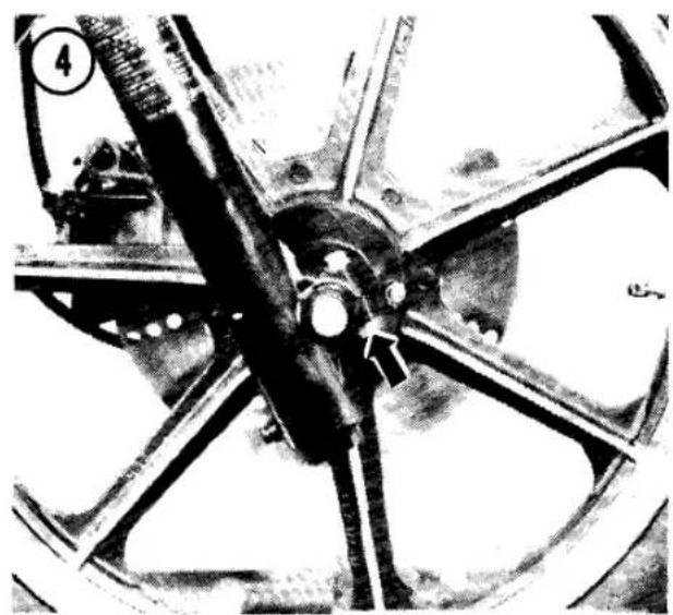

out and torque the brake disc mounting bolts as specified in Table 4.
- To install, reverse the removal steps. Note the following:
a. On models with no external tabs on the speedometer drive, the hub driver notches (Figure 7) must mate with the internal tabs in the speedometer drive.
b. On models with external tabs on the speedometer drive, the tabs must fit in the hub notches (Figure 8).
CAUTION
Make sure the speedometer drive tabs are correctly seated in both the wheel hub and in the speedometer drive gearbox before you tighten the axle nut or you may damage the drive.
c. Do not tighten the axle nut until after the speedometer cable is connected to the gearbox. Tighten the cable nut with pliers.

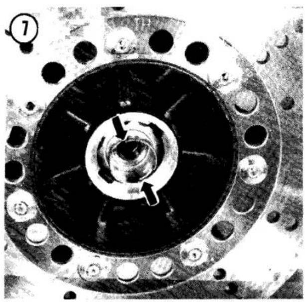
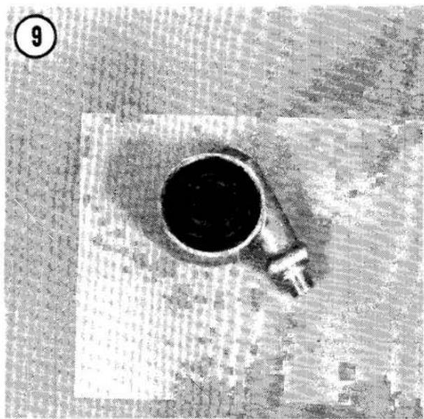


NOTE
If the cable won't seat easily, slowly turn the wheel until the cable end aligns with the drive.
d. Torque the axle nut, then the pinch nut as specified in Table 3.
e. Clean any oil or dirt from the brake disc with a non-oily solvent.
f. Install the brake caliper and torque the caliper mounting bolts as specified in Table 4.
g. After the wheel is installed, spin it to make sure it turns freely and apply the brake several times to make sure the pads are seated against the disc.
SPEEDOMETER GEAR LUBRICATION
On models with no external tabs on the speedometer drive (Figure 9), the speedometer drive gears at the front wheel should be lubricated with high-temperature grease according to the maintenance schedule (Table 1) in Chapter Three.
- Remove the front wheel from the motorcycle.
- Clean all old grease from the gear housing and gear, and pack the gearbox with high-temperature grease.
- Install the front wheel on the motorcycle.
REAR WHEEL
Removal/Installation (Drum Brake)
WARNING
When removing wheels with drum brakes or when working on drum brakes, be extremely careful not to inhale any of the dust from the brake linings. The brake linings contain asbestos fiber; asbestos has been connected with lung scarring and cancer. Do not use compressed air to clean the drum or linings. Dump any dust onto a newspaper and dispose of it in the trash. Wash your hands after handling the brake parts.
-
Support the motorcycle with the rear wheel off the ground.
-
Remove the safety clip and remove the rear brake anchor nut and lockwasher (A. Figure 10). Disconnect the anchor from the brake backing plate.
-
Unscrew the brake adjuster nut (B, Figure 10).
-
Remove the cotter pin and the axle nut (C, Figure 10) and pull out the axle.
-
Loosen the chain play adjuster locknuts (D, Figure 10) and the adjusters. Kick the rear wheel forward far enough to free the drive chain from the rear sprocket.
-
Remove the axle nut and pull out the axle.
-
Remove the wheel and brake assembly. There is a long spacer on the right side of the brake drum and a short spacer on the left side of the sprocket coupling.
-
To disassemble the wheel hub, see Figure 11 and refer to Wheel Bearings and Seals in this chapter.
-
To install, reverse the removal steps. Note the following:
a. Inspect the wheel coupling damper (A, Figure 12) and install a new one if worn.
b. Inspect the hub O-ring and grease it (B, Figure 12).
c. Clean any oil or dirt from the brake drum with a non-oily solvent.
d. Make sure the brake rod spring is in place before you connect the rod to the brake arm.
e. Adjust drive chain play, brake pedal play, and rear brake light switch operation as described in Chapter Three.
f. To center the brake shoes in the drum, tighten the axle nut lightly, spin the wheel and apply the brake forcefully, then torque the axle nut as specified in Table 3. Install a new cotter pin and spread its ends.
g. Torque the brake anchor nut as specified in Table 3.
h. After the wheel is installed, spin it to make sure it turns freely and apply the brake several times to make sure the brake is working properly.
Removal/Installation (Disc Brake)
-
Support the motorcycle with the rear wheel off the ground.
-
Loosen the rear brake caliper anchor bolt (Figure 13) and free the brake line from its guides on the swing arm.
-
Remove the cotter pin and loosen the axle nut (C, Figure 10).
-
Loosen the chain play adjuster locknuts (D, Figure 10) and the adjusters. Kick the rear wheel forward far enough to free the drive chain from the rear sprocket.
-
Remove the axle nut and pull out the axle while holding the caliper up. There is a long spacer on the right-hand side of the caliper, and a short spacer on the left side of the sprocket coupling.
-
Remove the rear wheel.

CAUTION
Do not set the wheel down on the brake disc surface. It may get warped or scratched.
NOTE
Insert the axle back through the swing arm and caliper or tie the caliper up to keep stress off the brake hose.
NOTE
You may want to insert a piece of wood in the caliper in place of the disc. If the brake pedal is accidentally pushed the caliper piston could be dislocated, which

may require caliper disassembly and brake system bleeding.
- To disassemble the wheel hub, see Figure 14 and refer to Wheel Bearings and Seals in this chapter. When installing a brake disc, face the marked side out and torque the brake disc mounting bolts as specified in Table 4.
- To install, reverse the removal steps. Note the following.
a. Inspect the wheel coupling damper (A, Figure 12) and install a new one if worn.
b. Inspect the hub O-ring and grease it (B, Figure 12).
c. Clean any oil or dirt from the brake disc with a non-oily solvent.
d. Adjust drive chain play, brake pedal play, and rear brake light switch operation as described in Chapter Three.

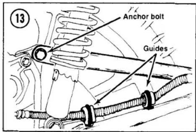
14
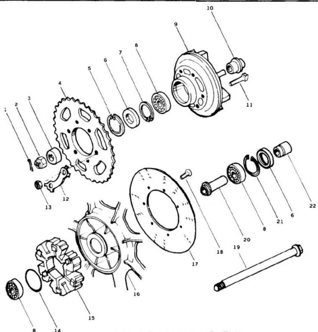
- Cotter pin
- Axle nut
- Collar
- Rear sprocket
- Circlip (1981 and later)
- Grease seal
-
Circlip (1979-1980)
-
Ball bearing
- Wheel coupler
- Coupler sleeve
- Sprocket bolt
- Lockplate
- Nut
-
O-ring
-
Rubber damper
- Rear wheel
- Disc
- Disc bolt
- Axle
- Spacer
- Circlip
- Collar
e. Torque the rear axle nut and brake anchor nut as specified in Table 3.
f. After the wheel is installed, spin it to make sure it turns freely and apply the brake several times to make sure the pads are seated against the disc.
Rear Sprocket Replacement
Replace the sprocket any time the teeth are worn or undercut as shown in Figure 15. A worn sprocket will quickly wear out a new drive chain.
Install a new sprocket with the numbered side facing out (Figure 16). Torque the sprocket nuts as specified in Table 3. If there are lockplates under the sprocket nuts, bend up a tab on the lockplate against each sprocket nut.
WHEEL BEARINGS AND SEALS
The original wheel bearings are not fully sealed and require periodic lubrication in accordance with the maintenance schedule (Table 1) in Chapter Three.
If bearing replacement is necessary, fully sealed bearings are available from any good bearing specialty shop. Be sure you take your old bearing along to ensure a perfect matchup. Fully sealed bearings provide better protection from dirt and moisture that may get into the hub.
Inspection and Lubrication
- Clean away all old grease.
- Check the inner and outer bearing races and balls for cracks, galling or pitting. Rotate the bearings by hand and check for roughness; they should make no noise (Figure 17). Replace any worn or damaged bearings.
- Pack the bearings thoroughly with high-temperature grease, forcing the grease around the balls.
- Inspect all grease seals for wear or damage and replace them if necessary.
Replacement
To disassemble the wheel hubs, refer to Figure 5, Figure 6, Figure 11 or Figure 14.
- Remove any seal retaining circlips (Figure 18).
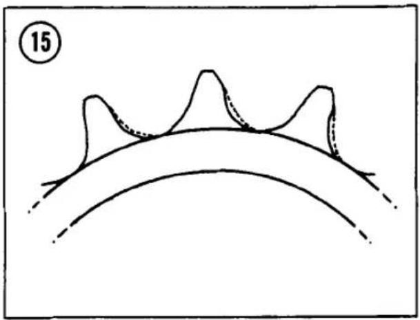


- Insert a rod into one side of the hub. Move the spacer aside and tap the bearing out the other side of the hub by working around its diameter (Figure 19).
NOTE
It is not necessary to remove the seal first. The seal will be driven out with the bearing.
-
Remove the spacer and tap out the opposite bearing.
-
Carefully drive a new bearing into its bore, tapping evenly around the outer race. Invert the hub and set the spacer in place. Install the other bearing on the axle and insert the axle through the spacer and the bearing that has been installed. Carefully tap the other bearing into its bore, tapping evenly around the outer race. Install a new seal into the bore and gently tap it into place.
NOTE
When installing semi-sealed wheel bearings, be sure the sealed side faces out.
AXLE
Support each axle in V-blocks 4 inches apart as shown in Figure 20 and check the runout with a dial indicator. Replace the axle if it is bent more than 0.028 in. (0.7 mm) or if it cannot be straightened to less than 0.008 in. (0.2 mm) runout.
NOTE
You can also check axle runout by rolling it on a piece of plate glass and slipping a feeler gauge under any visible gap.
TUBE-TYPE TIRES
The original tire cross-sectional sizes and tread pattern are often the best. See Table 5 for the standard sizes and inflation pressures.
Tubeless tires are used on some models. They are designated by the word "TUBELESS" cast into the tire sidewall (Figure 21) and are designed to be used only with tubeless rims that are dimensionally different from tube-type rims. These rims have "TUBELESS" stamped on them (Figure 22).

Read the section under Tubeless Tires before changing the tires.
WARNING
Do not install an inner tube inside a tubeless tire. The tube will cause an abnormal heat buildup in the tire.
WARNING
Do not install a tubeless tire on rims not originally equipped with tubeless tires. The tire bead may not seal properly. The tire could slip on the rim and sudden deflation could result.
Removal
CAUTION
On models with disc brakes, while removing a tire, support the wheel on 2 blocks of wood, so the brake disc doesn't contact the floor.
- Mark the valve stem location on the tire, so the tire can be installed in the same position for easier balancing.
- Remove the valve core to deflate the tire and remove the valve stem nut (Figure 23).
- Press the entire bead on both sides of the tire into the center of the rim. Use a rubber mallet or step on the tire with your heels.
- Lubricate the beads with soapy water.
- Insert a tire iron under the bead next to the valve (Figure 24). Force the bead on the opposite side of the tire into the center of the rim and pry the bead over the rim with the tire iron.
CAUTION
Use rim protectors (Figure 25) or insert scraps of leather between the tire irons and the rim to protect the rim from damage.
- Insert a second tire iron next to the first to hold the bead over the rim. Then work around the tire with the first tire iron, prying the bead over the rim (Figure 26). Be careful not to pinch the inner tube with the tire irons.
- Remove the valve from the hole in the rim and remove the tube from the tire.
NOTE
Step 8 is required only if you want to install a new tire.


- Stand the tire upright. Insert the tire iron between the second bead and the side of the rim that the first bead was pried over (Figure 27). Force the bead on the opposite side from the tire iron into the center of the rim. Pry the second bead off the rim, working around as with the first.
Installation
- Carefully inspect the tire for any damage, especially inside.
- If the tire has a directional arrow on the tire sidewall, it should point in the normal direction of rotation.
- Position the tire next to the rim with your mark at the valve stem hole.

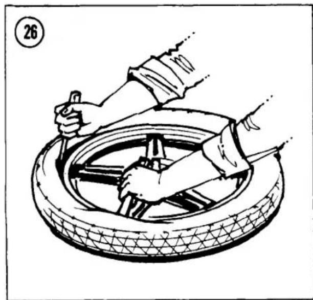
NOTE
A colored spot near the bead indicates a lighter point on the tire. This spot should be placed next to the valve stem (Figure 23).
- Inflate the tube just enough to round it out. Too much air will make installation difficult. Place the tube inside the tire.
- Lubricate both beads of the tire with soapy water.
- Push the backside of the tire down into the center of the rim and insert the valve stem through the stem hole in the wheel. The lower bead should go into the center of the rim and the upper bead outside. Work around the tire in


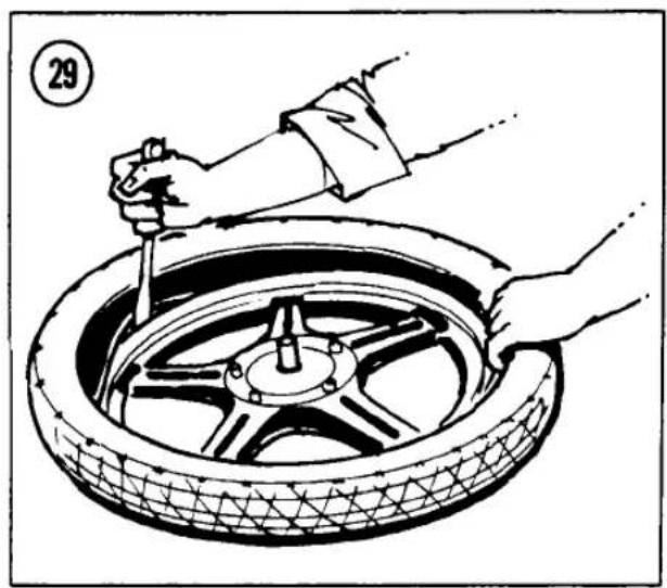

both directions (Figure 28). Use a tire iron for the last few inches of bead (Figure 29).
- Press the upper bead into the center of the rim opposite the valve. Pry the bead into the rim on both sides of the initial point with a tire iron, working round the rim to the valve (Figure 30).
- Wiggle the valve to be sure the tube is not under the bead. Set the valve squarely in its hole before screwing in the valve nut to hold it against the rim.
- Check the bead on both sides of the tire for an even fit around the rim. Inflate the tire slowly to seat the beads in the rim. It may be necessary to bounce the tire to complete the seating. Inflate to the required pressure.
- Balance the wheel as described in this chapter.
Inner Tube Repair
Every rider eventually experiences trouble with a tire or tube. Repairs and replacement are fairly simple and every rider should know the techniques.
Patching an inner tube should be considered only a temporary repair. A motorcycle tire flexes a great deal and could rub a patch off the tube. However, a patched tube will get you far enough to buy a new tube for maximum reliability and safety.
Tube repair kits can be purchased from motorcycle dealers and auto supply stores. When buying, specify that the kit you want is for motorcycles.
There are 2 types of tube repair kits: hot patch and cold patch. Hot patches are stronger because they actually vulcanize to the tube,

becoming part of it. However, they are far too bulky to carry for roadside repairs and the strength is unnecessary for a temporary repair.
Cold patches are not vulcanized to the tube; they are simply glued to it. Though not as strong as hot patches, cold patches are still very durable. Cold patch kits are less bulky than hot and are more easily applied while on the road. A cold patch kit containing everything necessary tucks in easily with your emergency tool kit.
Follow the instructions provided with the repair kit or use the following general instructions.
- Install the valve core into the valve stem and inflate the tube slightly. Do not overinflate.
- Immerse the tube in water a section at a time (Figure 31). Look carefully for bubbles indicating a hole. Mark each hole and continue checking until you are certain that all holes are discovered and marked. Also make sure that the valve core is not leaking; tighten it if necessary.
NOTE
If you do not have enough water to immerse sections of the tube, try running your hand over the tube slowly and very close to the surface. If your hand is damp, it works even better. If you suspect a hole anywhere, apply some saliva to the area to verify it.
- Roughen the area around the hole slightly larger than the patch; use a cap from the tire repair kit or a pocket knife. Do not scrape too

vigorously or you may cause additional damage.
- Apply a small quantity of the special cement to the puncture and spread it evenly with a finger.
- Allow the cement to dry until it's tacky—usually 30 seconds or so is sufficient.
- Remove the backing from the patch.
CAUTION
Do not touch the newly exposed rubber with your fingers or the patch will not stick firmly.
- Center the patch over the hole. Hold the patch firmly in place for about 30 seconds to allow the cement to set.
- Dust the patched area with talcum powder to prevent sticking.
- Carefully check inside the tire casing for glass particles, nails, or other objects which may have damaged the tube. If the inside of the tire is split, apply a patch to the area to keep it from pinching and damaging the tube again.
- Deflate the tube before installing in the tire.
TUBELESS TIRES
WARNING
Do not install an inner tube inside a tubeless tire. The tube will cause an abnormal heat buildup in the tire.
Tubeless tires have the word "TUBELESS" molded in the tire sidewall (Figure 32) and the rims have "TUBELESS" marked on them (Figure 33).


When a tubeless tire is flat, your best recourse is to take it to a motorcycle dealer for repair. Punctured tubeless tires should be removed from the rim to inspect the inside of the tire and to apply a combination plug/patch from the inside. Don't rely on a plug or cord repair applied from outside the tire. They might be okay on a car, but they're too dangerous on a motorcycle.
After repairing a tubeless tire, don't exceed 50 mph (80 kph) for the first 24 hours. Never race on a repaired tubeless tire. The patch could work loose from tire flexing and heat.
Removal/Installation
Removal of tubeless tires from their rims can be very difficult because of the exceptionally tight bead/rim seal. Breaking the bead seal may require the use of a special tool such as the one available from Kawasaki (Figure 34). If you have trouble breaking the seal, we recommend you take the tire to a motorcycle dealer.
CAUTION
The inner rim and tire bead area are sealing surfaces on a tubeless tire. Do not scratch the inside of the rim or damage the tire bead.
Tubeless tire removal and installation is similar to that of tube-type tires, with these additional requirements:
- Install a new valve stem (Figure 35) whenever you have the tire off the rim. Rubber deteriorates with age and valve stem replacement will never be as convenient as now.
- After the tire is on the rim, bounce the wheel several times while turning the wheel. This
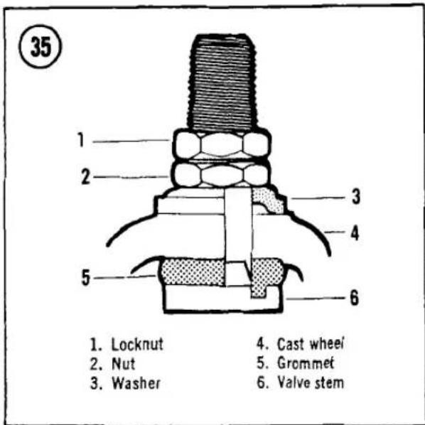

helps seat the bead. If an initial air seal is hard to get, your motorcycle or auto repair shop may have a bead seater to make the job easy.
- After inflating the tire, check to see that the beads are fully seated and that the tire rim lines are the same distance from the rim all the way around the tire. If the beads won't seat, deflate the tire, relubricate the rim and beads with soapy water and reinflate the tire.
Repair
Do not rely on a plug or cord patch applied from outside the tire. Use a combination plug/patch applied from inside the tire (Figure 36).

- Remove the tire from the rim.
- Inspect the rim inner flange. Smooth any scratches on the sealing surface with emery cloth. If a scratch is deeper than 0.5 mm (0.020 in.), the wheel should be replaced.
- Inspect the tire inside and out. Replace a tire if any of the following is found:
a. A puncture larger than 1/8 in. (3 mm) diameter
b. A punctured or damaged sidewall
c. More than 2 punctures in the tire
- Apply the plug/patch, following the instructions supplied with the patch.
BRAKES
Some models are equipped with hydraulic disc brakes at the front and rear wheels and some models have a hydraulic disc brake at the front with a drum brake at the rear.
Repair of brake systems is extremely critical work. Don't take shortcuts and don't work with makeshift tools. When a procedure calls for a locking agent, such as Loctite Lock N' Seal, use it. If a torque specification is given, use a torque wrench. Recheck your work and, when you're finished, test your brakes in a safe area. If you have any doubts about your ability to do the job according to these procedures, have the work done by your Kawasaki dealer.
See Table 1 and Table 2 for brake wear limits. See Table 4 for disc brake system torque specifications.
HYDRAULIC DISC BRAKES
WARNING
Brake fluid is an irritant. Keep it away from your eyes and off your skin.
WARNING
When removing wheels with drum brakes or when working on drum brakes, be extremely careful not to inhale any of the dust from the brake linings. The brake linings contain asbestos fiber; asbestos has been connected with lung scarring and cancer. Do not use compressed air to clean the drum or linings. Dump any dust onto a newspaper and dispose of it in the trash. Wash your hands after handling the brake parts.
The following precautions must be observed when servicing brake systems.
-
Never reuse old brake fluid.
-
Never use fluid from a container that has been left open.
-
Use only disc brake fluid clearly marked DOT 3 or higher. Don't mix different rated brake fluids together.
-
Don't leave the fluid reservoir cap off for too long. The fluid will absorb moisture from the air and will boil at lower temperatures.
-
Don't contaminate the brake discs or pads with brake fluid, gasoline or any lubricants (including graphite or pencil lead).
-
Brake fluid can ruin paint and plastic. If you spill any, wipe it up immediately.
-
If you open a bleed valve or loosen a brake line fitting, bleed air from the system as described in this chapter.
BRAKE SYSTEM BLEEDING
Bleed the hydraulic brake system whenever the brake lever or pedal action feels spongy or soft, after brake fluid has been changed or whenever a brake line fitting has been loosened.
- Remove the reservoir cap and add brake fluid. Don't let the fluid level drop below the minimum during this procedure or air will enter the system and you'll have to start over.
- Install the reservoir cap. Connect a clear plastic hose to the bleed valve at the caliper (Figure 37). Run the other end of the hose into
a clean container. Fill the container with enough brake fluid to keep the end submerged (Figure 38).
NOTE
On dual hydraulic disc models, always bleed the caliper farther away from the master cylinder first. Otherwise air bubbles may remain in the brake system.
-
Slowly apply the brake lever or pedal several times. Hold the lever or pedal in the applied position. Open the bleed valve about one-half turn. Allow the lever or pedal to travel to its limit. When this limit is reached, tighten the bleed screw. As the fluid enters the system, the level will drop in the reservoir. Maintain the level at about 3/8 in. (10 mm) from the top of the reservoir to keep air from being drawn into the system.
-
Continue to pump the lever or pedal, open and close the bleed valve and fill the reservoir until the fluid emerging from the hose is completely free of bubbles.
NOTE
Do not allow the reservoir to empty during the bleeding operation or more air will enter the system. If this occurs, the entire procedure must be repeated.
-
Hold the lever or pedal down, tighten the bleed valve, remove the bleed tube and install the bleed valve dust cap.
-
Add fluid to correct the level in the reservoir. Slowly pump the brake lever or pedal several times (reservoir cap still off) until no air bubbles rise up through the fluid from holes at the bottom of the reservoir (this bleeds air from the master cylinder end of the line). Install the reservoir cap tightly.
-
Test the feel of the brake lever or pedal. It should be firm and should offer the same resistance each time it's operated. If it feels spongy, it is likely that there is still air in the system and it must be bled again.
WARNING
Do not ride the motorcycle until you are sure the brakes are working with a solid feel.

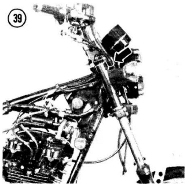
BRAKE FLUID CHANGE
Change the brake fluid according to the maintenance schedule (Table 1, Chapter Three), or whenever the fluid becomes contaminated by water or dirt. Brake fluid changing is the same as bleeding, except you keep the bleed valve open and pump the lever or pedal until all fluid runs out of the system. After draining, fill and bleed the system.

43


BRAKE LINE REPLACEMENT
A brake hose should be replaced whenever it shows cracks, bulges or other damage. The deterioration of rubber by ozone and other atmospheric elements may require hose replacement every 5 years.
- Before replacing a brake hose, inspect the routing of the old hose carefully, noting any guides and grommets the hose may go through (Figure 39, Figure 40 and Figure 41).
- Drain the brake fluid from the system as described in Brake Fluid Change in this chapter.
- Disconnect the banjo bolts securing the hose at either end (Figure 42 and Figure 43) and remove the hose with its banjo bolts and 2 washers at both ends.
- Install a new hose. Place a new washer on each side of each banjo bolt.
- On models with a rear disc brake, be sure to route the brake hose through the guide grommets on the swing arm (Figure 41).
- Torque the banjo bolts as specified in Table 4.
- Fill the reservoir and bleed the system as described under Brake System Bleeding in this chapter.
DISC BRAKE PAD REPLACEMENT
There is no recommended mileage interval for changing the friction pads in the disc brake.


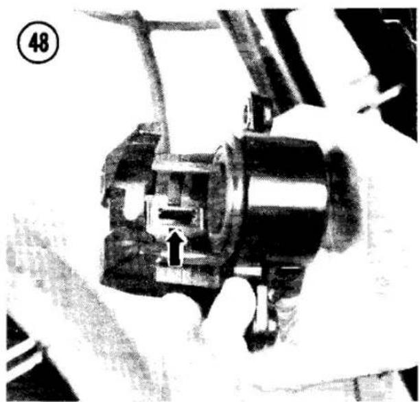

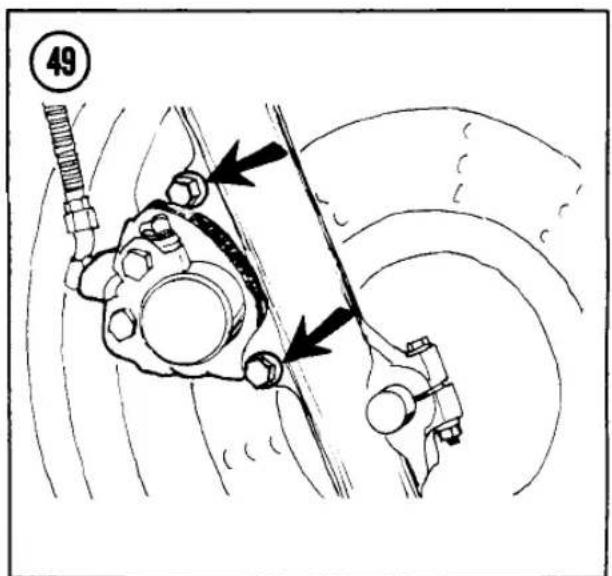

Pad wear depends greatly on riding habits and conditions. See Brake Pad Inspection in Chapter Three.
Always replace all pads (2 per disc) at the same time.
Front Brake Pad Removal (All 1981 Models and 1980 KZ550-C)/ Rear Brake Pad Removal (All 1981 Models)
- Remove the 2 caliper mounting bolts and lift the caliper off the pad holder (Figure 44).
- Remove the brake pads.
Front Brake Pad Installation (All 1981 Models and 1980 KZ550-C)/ Rear Brake Pad Installation (All 1981 Models)
- Remove the cap from the master cylinder and slowly push the piston (Figure 45) into the caliper while checking the reservoir to make sure it doesn't overflow. The piston should move freely. You may need to use a C-clamp to push the piston back into the caliper. If the piston sticks, remove the caliper and have it rebuilt by your Kawasaki dealer.
- Make sure the brake pad guides are in place (Figure 46).
- Install the pads with the friction material toward the disc (Figure 47).
-
Make sure the anti-rattle spring is installed in the caliper (Figure 48).
-
Install the caliper. Torque the caliper bolts (Figure 44) as specified in Table 4. a new hose. Place a new washer on each side of each banjo bolt.
- Support the motorcycle with the wheel off the ground. Spin the wheel and pump the brake until the pads are seated against the disc.
- Top up the fluid level in the master cylinder if necessary and reinstall the cap.
WARNING
Do not ride the motorcycle until you are sure the brakes are working with a solid feel. If necessary, bleed the brakes to remove any accumulated air from the system.
Front Brake Pad Removal (1979-1980 KZ550-A, KZ500)
- Remove the 2 caliper mounting bolts (Figure 49) and lift the caliper off the brake disc.
- Remove the screw, lockwasher and plate securing the inboard pad.
- Remove the inboard pad.
- Slide the caliper holder toward the bleed valve and remove the outboard pad.
NOTE
If the pad won't come out, squeeze the brake lever a few times until the piston pushes the pad out.
Front Brake Pad Installation (1979-1980 KZ550-A, KZ500)
- Remove the cap from the master cylinder and slowly push the piston into the caliper while checking the reservoir to make sure it doesn't overflow. The piston should move freely. You may need to use a C-clamp to push the piston back into the caliper. If the piston sticks, remove the caliper and have it rebuilt by your Kawasaki dealer.
- Install the outboard pad against the caliper piston, with the stepped side of the pad toward the disc (Figure 50).
- Install the inboard pad, aligning the tab on the pad with the groove in the caliper (Figure 51). Use Loctite Lock N' Seal on the mounting screw threads.
- Install the caliper. Torque the caliper mounting bolts as specified in Table 4.
- Support the motorcycle with the front wheel off the ground. Spin the front wheel and pump

the brake lever until the pads are seated against the disc.
- Top up the fluid level in the master cylinder if necessary, and install the cover.
WARNING
Do not ride the motorcycle until you are sure the brakes are working with a solid feel. If necessary, bleed the brakes to remove any accumulated air from the system.
Rear Brake Pad Removal (1979-1980 KZ500)
- Remove the pad cover from the caliper.
- See Figure 52. Remove the clips from the pins, then hold your thumb on the anti-rattle springs to keep them from flying off. Pull the pins off the caliper.
- Remove the pads from the caliper.
Rear Brake Pad Installation (1979-1980 KZ500)
- Remove the cap from the master cylinder and slowly push the piston into the caliper while checking the reservoir to make sure it doesn't overflow. The piston should move freely. You may need to use a C-clamp to push the piston back into the caliper. If the piston sticks, remove the caliper and have it rebuilt by your Kawasaki dealer.
- Insert the pads with the friction material facing the disc.
CAUTION
Don't dislocate the rubber piston dust seals while inserting the pads.
- Insert 2 pins through the outer wall of the caliper and outboard pad. The end with the hole goes toward the outside.
- Install the anti-rattle spring with the ends under the pins and the top portion on top of the pad (Figure 53).
- Install the other pad in the same manner as the first. Press down on the anti-rattle springs so the pin goes over the ends of the springs.
- Install the clips through the holes in the pins, between the outboard pad and the caliper.
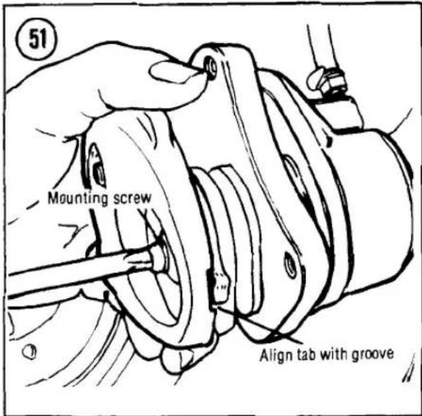
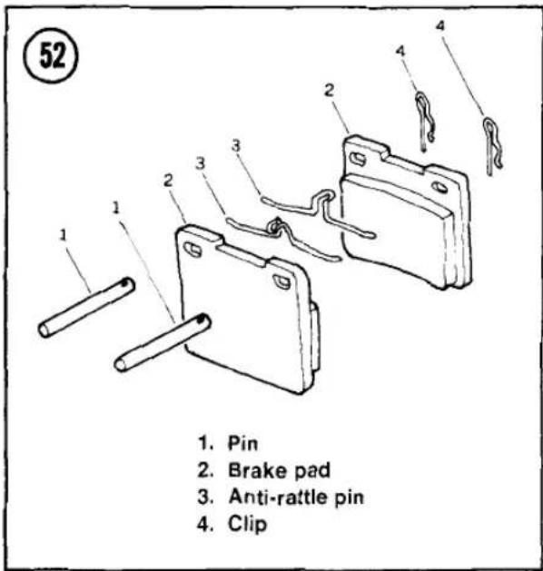
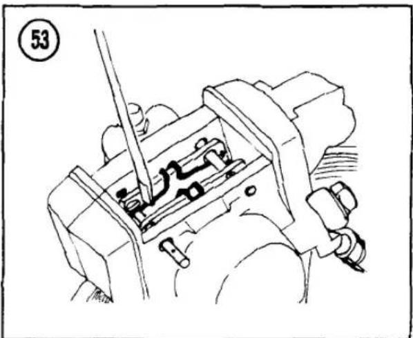
54

FRONT BRAKE CALIPER (1979-1980 KZ500; 1980 KZ550 A, B)
-
Holder shaft (2)
-
Bleed valve
-
Caliper
-
Spacer (2)
-
Nut (2)
-
Mounting bolt (2)
-
Fluid seal
-
Piston
-
Dust cover
-
Outboard pad
-
Dust cover (4)
-
O-ring (4)
-
Caliper holder
-
Inboard pad
-
Metal plate
-
Lockwasher
-
Screw
WARNING
Do not forget to install these clips. They keep the brake pins and pads in place. If these are lost, it could result in loss of braking at the rear wheel.
- Install the cover.
- Block the motorcycle up so that the rear wheel is off the ground. Spin the rear wheel and activate the brake pedal for as many times as it takes to refill the cylinder in the caliper and correctly locate the pads.
- Refill the fluid in the reservoir, if necessary, and install the top cap.
WARNING
Do not ride the motorcycle until you are sure that the brake is operating correctly with full hydraulic advantage. If necessary, bleed the brakes.
DISC BRAKE CALIPERS
Rebuilding
See Figure 54, Figure 55, Figure 56 or Figure 57. If the caliper leaks, it should be rebuilt. If the piston sticks in the cylinder, indicating severe wear or galling, the entire unit should be replaced. The factory recommends that the
55

FRONT BRAKE CALIPER (ALL 1981 AND LATER; 1980 KZ550-C)
- Holder shaft (front)
- Dust cover
- Caliper holder
- Pad guide (2)
- Brake pads
- Holder shaft (rear)
-
Friction boot
-
Bleed valve
- Caliper shaft bolt (2)
- Anti-rattle spring
- Caliper
- Fluid seal
- Piston
- Dust cover
56

REAR BRAKE CALIPER
(1979-1980 KZ500)
- Allen bolt (2)
- Bleed valve
- Caliper half
- Fluid seal
- Piston
- Dust cover
- Pins
-
Brake pads
-
Anti-rattle springs
- Clips
- Dust cover
- Piston
- Fluid seal
- Caliper half
- Inspection cover

57
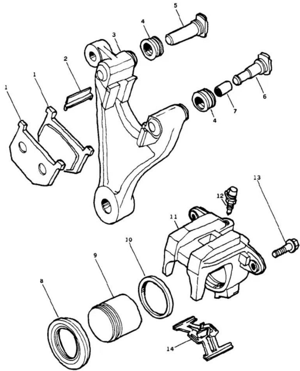
REAR BRAKE CALIPER (1981 AND LATER)
- Brake pads
- Pad guide (2)
- Caliper holder
- Dust covers
- Front holder shaft
- Rear holder shaft
-
Friction boot
-
Dust cover
- Piston
- Fluid seal
- Caliper
- Bleed valve
- Caliper shaft bolt (2)
- Anti-rattle spring
piston fluid seal and dust cover be replaced every other time the pads are replaced.
Rebuilding a leaky caliper requires special tools and experience. We therefore recommend that caliper service be entrusted to your Kawasaki dealer or brake specialist. You will save time, money and possibly your life by removing the caliper yourself and having a professional do the job.
See Table 1 at the end of the chapter for brake wear limits.
WARNING
Do not ride the motorcycle until you are sure the brakes are operating properly.
Caliper Removal/Installation
Remove and install the calipers as described under Disc Brake Pad Replacement or Rear Wheel Removal, and Brake Line Replacement in this chapter.
MASTER CYLINDER REBUILDING
If the master cylinder leaks, it should be rebuilt. If the piston sticks in the cylinder, indicating severe wear or galling, the entire unit should be replaced. Rapid darkening of fresh brake fluid is an indication that rubber parts inside the master cylinder have deteriorated.
Rebuilding a master cylinder requires special tools and experience. We therefore recommend that service be entrusted to your Kawasaki dealer or brake specialist. You will save time, money, and possibly your life by removing the master cylinder yourself and having a professional do the job.
See Table 1 at the end of the chapter for brake wear limits.
FRONT MASTER CYLINDER
Removal
See Figure 58.
- Remove the right rear view mirror.
- Push up on the front brake light switch locking tab under the lever bracket (Figure 59) and pull the switch free from the lever bracket.
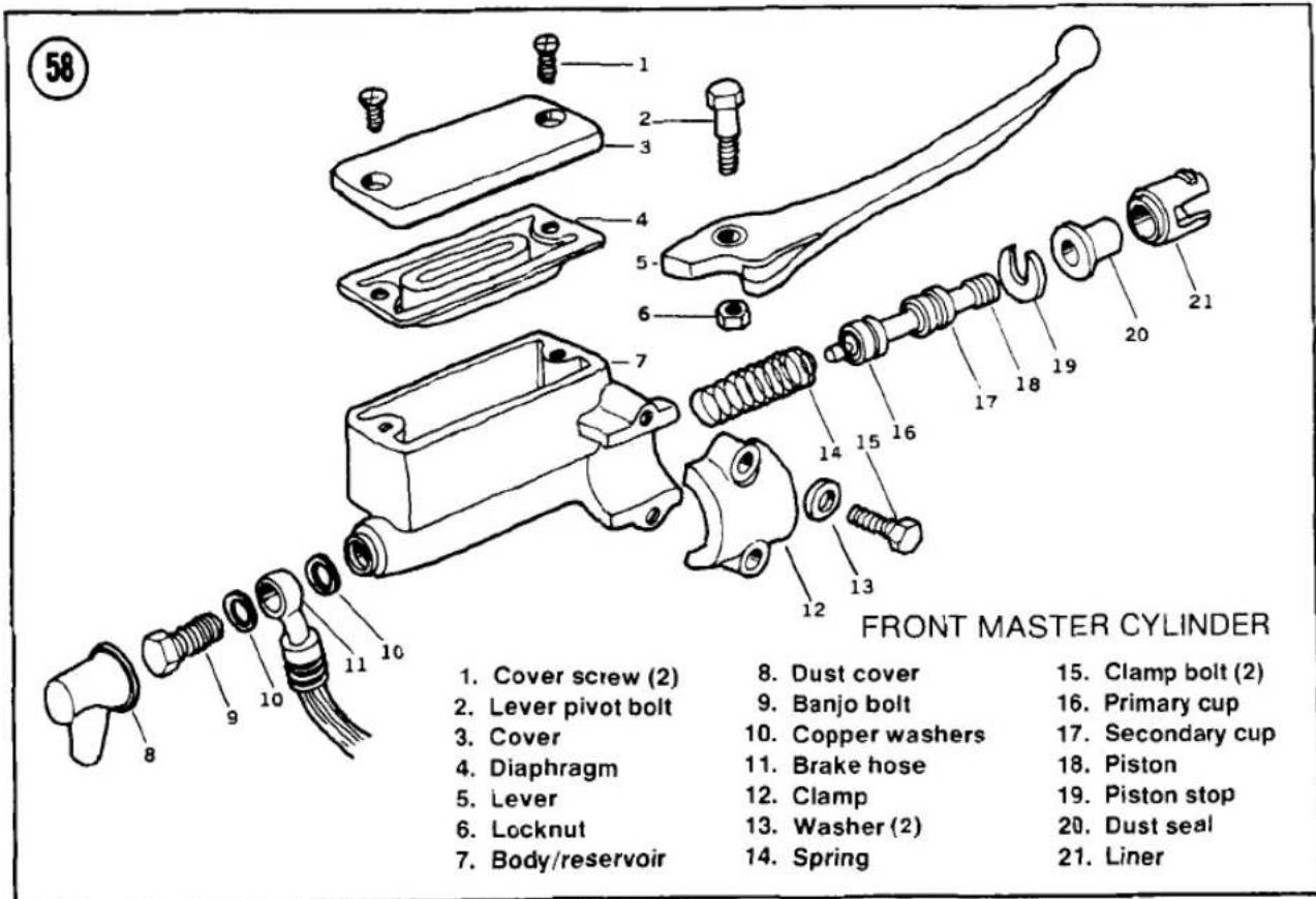

- Pull back the rubber boot and remove the banjo bolt (Figure 60) securing the brake hose to the master cylinder.
CAUTION
Brake fluid ruins paint and plastic surfaces. If you spill any, wipe it up immediately.
- Remove the 2 master cylinder clamp bolts and the clamp. Take off the master cylinder.
Installation
- Install the master cylinder with the projection on the clamp toward the throttle grip (A. Figure 61).
- Install the clamp bolts and washers (B, Figure 61). Tighten the upper bolt first, then the lower one.
- Connect the brake line. Use a new washer on either side of the banjo bolt and torque it as specified in Table 4.
- Bleed the brake system as described in this chapter.
REAR MASTER CYLINDER
The 1981 and later models use a rear master cylinder with a remote fluid reservoir. The 1979-1980 KZ500 reservoir is part of the master cylinder.
Removal
See Figure 62 or Figure 63.
- Remove the right side cover.
- On the KZ550-D, remove the bolt that mounts the fluid reservoir to the frame.
- Remove the banjo bolt that connects the master cylinder to the rear brake hose.
CAUTION
Brake fluid ruins paint and plastic surfaces. If you spill any, wipe it up immediately.
- Remove the 2 rear master cylinder mounting bolts. Pull the master cylinder free of the brake pushrod and dust cover.
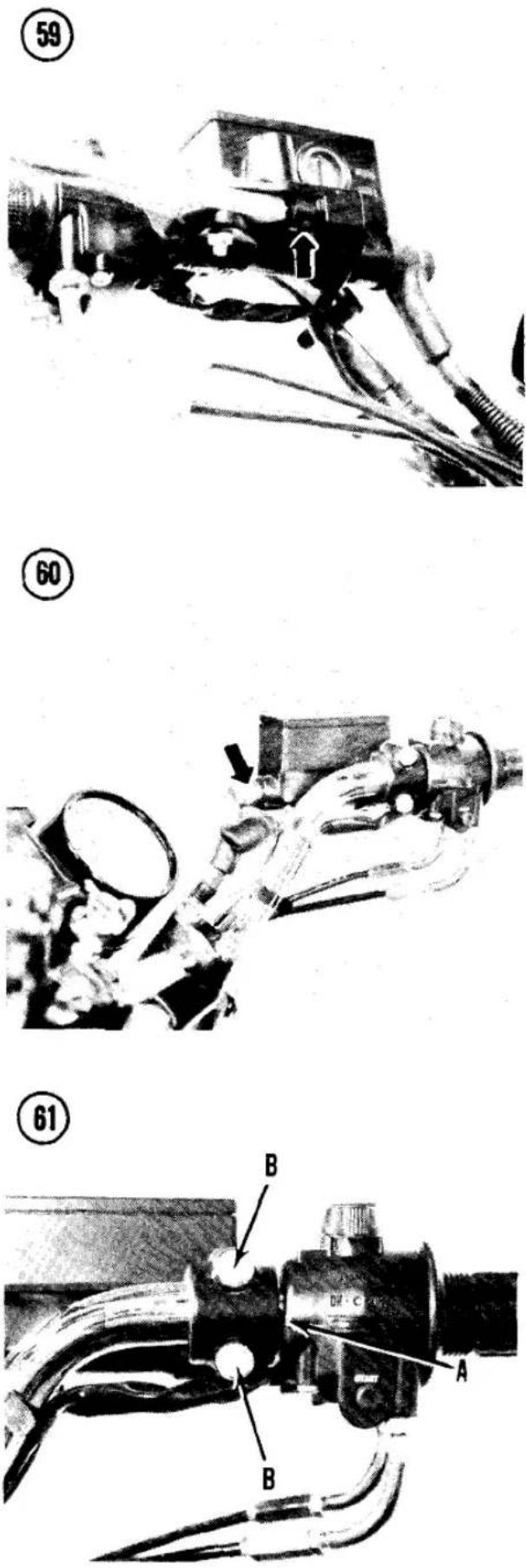
62
REAR MASTER CYLINDER
(1981 AND LATER)

- Banjo bolt
- Copper washers
- Brake hose
- Mounting bolts
- Body
- Spring
- Primary cup
- Piston
-
Retainer
-
Boot
- Pushrod
- Locknut
- Clevis
- Pin
- Cotter pin
- Cap
-
Washer
-
Diaphragm
- Reservoir
- Bolt
- Clamp
- Hose
- Clamp
- Elbow
- Grommet


Installation
- Inspect the pushrod boot on the bottom of the master cylinder. Install a new one if cracked or worn.
- Install the master cylinder on the pushrod and pull the rubber boot up into place on the cylinder.
- Torque the 2 master cylinder mounting bolts as specified in Table 4.
-
Connect the brake lines. Use a new washer on both sides of the banjo bolt and torque it as specified in Table 4.
-
Bleed the brake system as described in this chapter.
-
Adjust the rear brake; see Brake Pedal Play in Chapter Three.
BRAKE DISCS
Inspection
It is not necessary to remove the disc from the wheel to inspect it. Small marks on the disc are not important, but scratches deep enough to snag a fingernail reduce braking effectiveness and increase pad wear.

- Measure the thickness at several points around the disc with vernier calipers or a micrometer (Figure 64). The disc must be replaced if the thickness, at any point, is less than the limit in Table 1.
- Check the disc runout with a dial indicator. Raise the wheel being checked and set the arm of the dial indicator against the surface of the disc (Figure 65) and slowly rotate the wheel while watching the indicator. If the runout is greater than specified in Table 1, replace as necessary.
Removal/Installation
See Front Hub Disassembly or Rear Hub Disassembly in this chapter for brake disc replacement. Check the disc runout after installing the disc.
DRUM BRAKE
Some KZ550 models are equipped with a single leading shoe drum brake at the rear wheel. This type of brake has a single brake actuating cam, one "leading" shoe that does most of the work and one "trailing" shoe that does less work.
WARNING
When removing wheels with drum brakes or when working on drum brakes, be extremely careful not to inhale any of the dust from the brake linings. The brake linings contain asbestos fiber; asbestos has been connected with lung
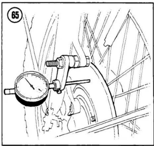
scarring and cancer. Do not use compressed air to clean the drum or linings. Dump any dust onto a newspaper and dispose of it in the trash. Wash your hands after handling the brake parts.
Disassembly/Assembly
- See Figure 66. Remove the wheel from the motorcycle as described in this chapter. Remove the backing plate and brake assembly as a unit from the hub.
- Remove the brake shoes and springs by prying them off with a screwdriver (Figure 67).
- Make a mark across the brake cam end and the arm so that the arm can be reinstalled in the original position, then remove the pinch bolt and brake arm (Figure 68).
- Remove the brake cam (A, Figure 69).
- Thoroughly clean the brake cam and backing plate.
- Perform Drum Brake Inspection as described in this chapter.
- To assemble the brake, reverse this procedure. Note the following:
a. Lubricate the brake shoe pivot (B. Figure 69), the brake cam face and the groove around the shaft (A) with a small amount of high-temperature grease. Be careful not to contaminate the brake linings or drum.
b. Install the dust seal on the brake cam shaft (Figure 70) and install the wear indicator so that it points to the far right
66

DRUM BRAKE
- Brake shoes
- Return spring (2)
- Brake camshaft
-
Backing plate
-
Felt washer
- Wear indicator
- Brake arm
- Pinch bolt
67

68
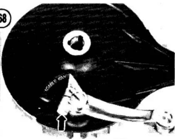


end of the "USABLE RANGE" mark (Figure 68).
c. Make sure the brake return springs and shoes are securely seated (Figure 71).
d. Adjust the rear brake light switch: see Rear Brake Light Switch Adjustment in Chapter Three.
Inspection
-
Examine the brake linings for oil or grease contamination. Contaminated linings must be replaced.
-
Measure the thickness of the lining at its thinnest part (Figure 72). Replace both shoes when any portion of the lining is worn down to 0.1 in. (2.5 mm).
-
Use vernier calipers and check brake drums for excessive wear (Figure 73). Standard brake drum diameter is 180 mm. If the drum is worn to a diameter more than 180.75 mm the wheel hub must be replaced for safety.
-
Check the brake shoe return spring free length (Figure 74). If the springs are stretched and weak, they won't fully retract the shoes from the drum, resulting in a power-robbing drag on the drums and rapid wear of the lining. Replace the springs if they are longer than the limit given in Table 2.

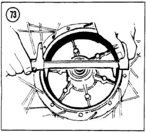

Table 1 DISC BRAKE WEAR LIMITS
| Calliper/Disc | |
| 1979-1980 KZ500, KZ550-A | |
| Caliper ID | 1.506 in. (38.25 mm) |
| Caliper piston OD | 1.499 in. (38.08 mm) |
| 1980 KZ550-B, C, all 1981 models | |
| Caliper ID | 1.690 in. (42.92 mm) |
| Caliper piston OD | 1.683 in. (42.75 mm) |
| Disc runout | 0.012 in. (0.3 mm) |
| Disc thickness-front (dual) | 0.177 in. (4.5 mm) |
| Disc thickness-front (single) | 0.236 in. (6.0 mm) |
| Disc thickness-rear | 0.236 in. (6.0 mm) |
| Pad thickness | 0.040 in. (1.0 mm) |
| Front Master Cylinder (Dual Disc) | |
| 1979-1980 KZ500 | |
| Cylinder ID | 0.628 in. (15.95 mm) |
| Piston OD | 0.622 in. (15.80 mm) |
| Primary cup OD | 0.630 in. (16.0 mm) |
| Secondary cup OD | 0.646 in. (16.4 mm) |
| Spring free length | 1.37 in. (34.7 mm) |
| Front Master Cylinder (Dual Disc) | |
| 1981 KZ500B, KZ550-B, D | |
| Cylinder ID | 0.628 in. (15.95 mm) |
| Piston OD | 0.617 in. (15.67 mm) |
| Primary cup OD | 0.630 in. (16.0 mm) |
| Secondary cup OD | 0.646 in. (16.4 mm) |
| Spring free length | 1.37 in. (34.8 mm) |
| Front Master Cylinder (Single Disc) | |
| 1980-1981 KZ550-C, 1981 KZ550-A | |
| Cylinder ID | 0.503 in. (12.78 mm) |
| Piston OD | 0.492 in. (12.50 mm) |
| Primary cup OD | 0.504 in. (12.8 mm) |
| Secondary cup OD | 0.516 in. (13.1 mm) |
| Spring free length | 1.86 in. (47.2 mm) |
| Rear Master Cylinder | |
| 1979-1980 KZ500 | |
| Cylinder ID | 0.628 in. (15.95 mm) |
| Piston OD | 0.622 in. (15.80 mm) |
| Primary cup OD | 0.642 in. (16.3 mm) |
| Secondary cup OD | 0.642 in. (16.3 mm) |
| Spring free length | 1.46 in. (37.2 mm) |
| Rear Master Cylinder | |
| 1981 KZ500, KZ550-B, D | |
| Cylinder ID | 0.554 in. (14.08 mm) |
| Piston OD | 0.543 in. (13.80 mm) |
| Primary cup OD | 0.551 in. (14.0 mm) |
| Secondary cup OD | 0.575 in. (14.6 mm) |
| Spring free length | 1.28 in. (32.4 mm) |

Table 2 DRUM BRAKE WEAR LIMITS
| Camshaft journal OD | 0.663 in. (16.83 mm) |
| Camshaft hole ID | 0.678 in. (17.22 mm) |
| Drum ID | 7.116 in. (180.75 mm) |
| Return spring free length | 2.72 in. (69.0 mm) |
| Shoe lining thickness | 0.10 in. (2.5 mm) |
Table 3 CHASSIS TORQUES
| Item | Ft.-lb. | Mkg |
| Brake pedal pivot cap nut | 14.5 | 2.0 |
| Front axle nut | 60 | 8.0 |
| Front axle pinch bolt | 14.5 | 2.0 |
| Fork clamp bolts | 13 | 1.8 |
| Fork air valves | 8.5 | 1.2 |
| Fork bottom Allen bolt | 13 | 1.8 |
| Handlebar clamp bolts | 13 | 1.8 |
| Rear axle nut | 60 | 8.0 |
| Rear sprocket nuts | 30 | 4.0 |
| Shock absorber mounts | 22 | 3.0 |
| Steering head clamp bolt | 13 | 1.8 |
| Steering head top bolt | 35 | 4.5 |
| Steering head adjuster locknut | 22 | 3.0 |
| Swing arm pivot nut | 60 | 8.0 |
| Torque link nuts | 22 | 3.0 |
| Item | Ft.-lb. | Mkg |
| Banjo bolts | 22 | 3.0 |
| Bleed valve | 70 in.-lb. | 0.80 |
| Brake lever pivot bolt | 25 in.-lb. | 0.30 |
| Brake lever pivot locknut | 50 in.-lb. | 0.60 |
| Caliper holder shaft nuts | ||
| 1979-1980 KZ500, KZ550-A | 19 | 2.6 |
| Caliper holder shaft nuts | ||
| 1980-1981 KZ550-C, all 1981 | 13 | 1.8 |
| Caliper mounting bolts | ||
| 1979-80 KZ500, KZ550-A | 22 | 3.0 |
| 1980-81 KZ550-C, all 1981 | 30 | 4.0 |
| Disc mounting bolts | 16.5 | 2.3 |
| Rear caliper Allen bolts(1979-1980 KZ500 only) | 22 | 3.0 |
| Master cylinder clamp bolts | 80 in.-lb. | 0.90 |
Table 5 KZ500/550 TIRES AND TIRE PRESSURE
| Model/Tire Size | Pressure @ Load | |
| 0-215 lb.(0-97.5 kg) | Over 215 lb.(Over 97.5 kg) | |
| KZ500-B1,B2, KZ550-A1 (Tube-type) | ||
| Front—3.25H-19 4PR | 28 psi (200 kPa) | 28 psi (200 kPa) |
| Rear—3.75H-18 4PR | 36 psi (250 kPa) | 40 psi (280 kPa) |
| KZ500-B3, KZ550-A2,B2,D1 (Tubeless) | ||
| Front—3.25H-19 4PR | 28 psi (200 kPa) | 28 psi (200 kPa) |
| Rear—3.75H-18 4PR | 32 psi (225 kPa) | 40 psi (280 kPa) |
| KZ550-C1, C2 (Tubeless) | ||
| Front—3.25S-19 4PR | 25 psi (175 kPa) | 25 psi (175 kPa) |
| Rear—130/90-16 67H 4PR | 21 psi (150 kPa) | 28 psi (200 kPa) |
NOTE: If you own a 1982 or later model, first check the Supplement at the back of the book for any new service information.
CHAPTER TEN
CHASSIS
This chapter covers the front forks, steering head, rear shock absorbers and swing arm.
Chassis wear limits and torque specifications are given in Table 1 and Table 2 at the end of the chapter.
FAIRING
The KZ550-D is factory-equipped with a cafe-racer style fairing. See Figure 1 for fairing and windscreen removal and installation.
FRONT FORKS
The Kawasaki front suspension consists of a spring-controlled, hydraulically damped telescopic fork. The damping rate is determined by the viscosity (thickness) of the oil used. The spring rate can be altered by varying the amount of oil used and, on some models, the air pressurization of the forks; refer to Chapter Three for these adjustments. Before suspecting major trouble, drain the fork oil and refill with the proper type and quantity. If you still have trouble, such as poor damping, tendency to bottom out or top out or leakage around the fork seals, then follow the service procedures in this section.
To simplify fork service and to prevent the mixing of parts, the fork legs should be removed, serviced and reinstalled individually.
Each front fork leg consists of the fork leg (inner tube), slider (outer tube), fork spring and damper rod with its damper components.
Removal/Installation
- Raise the front wheel off the ground; support the motorcycle securely under the engine.
- Remove the front wheel; see Front Wheel Removal in Chapter Nine.
- Remove the front fender.
- Loosen the upper and lower fork clamp bolts (Figure 2).
- Work the fork leg down and out of the clamps with a twisting motion.
- Install by reversing the removal steps. Note the following.
a. The top of the fork tube should be even with the top of the clamp (Figure 3).
CAUTION
Both fork assemblies must be installed at exactly the same height to prevent axle and suspension damage when the suspension is bottomed or fully extended.
①
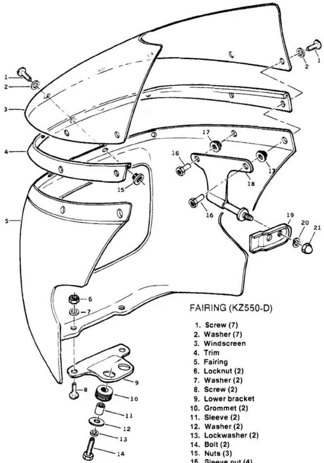
- Screw (7)
- Washer (7)
- Windscreen
- Trim
- Fairing
- Locknut (2)
- Washer (2)
- Screw (2)
- Lower bracket
- Grommet (2)
- Sleeve (2)
- Washer (2)
- Lockwasher (2)
- Bolt (2)
- Nuts (3)
- Sleeve nut (4)
- Grommet (4)
- Side bracket (2)
- Bracket (2)
- Lockwasher (2)
- Cap nut (2)
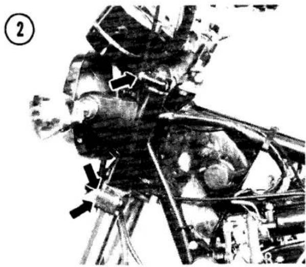
b. Torque the fork mounting bolts as specified in Table 2.
Disassembly
Refer to Figure 4 or Figure 5. Disassembly of the fork leg requires special tools and patience. If you have trouble taking the fork leg apart, take it to your Kawasaki dealer to keep from damaging it or hurting yourself. Minor variations exist among models. Pay particular attention to the location and positioning of spacers, washers and springs to make assembly easier.
- On models with air pressurized forks, release any air pressure from the fork leg by removing the rubber cap from the top of the fork and pushing in the valve core until all pressure is released.
- Hold the upper fork tube in a vise with a rubber sheet to grip the tube (Figure 6). Remove the top plug by pushing the plug in and prying out the circlip (Figure 7).
WARNING
The fork is assembled with spring preload. Keep your face away from the fork end. The plug may spring out.
- Remove the top plug and fork spring.
- Remove the fork from the vise, pour the oil out and discard it. Pump the fork several times by hand to expel the remaining oil.
- Clamp the fork slider in a vise with a rubber sheet to grip the slider.
- Remove the Allen bolt and gasket from the bottom of the slider (Figure 8).
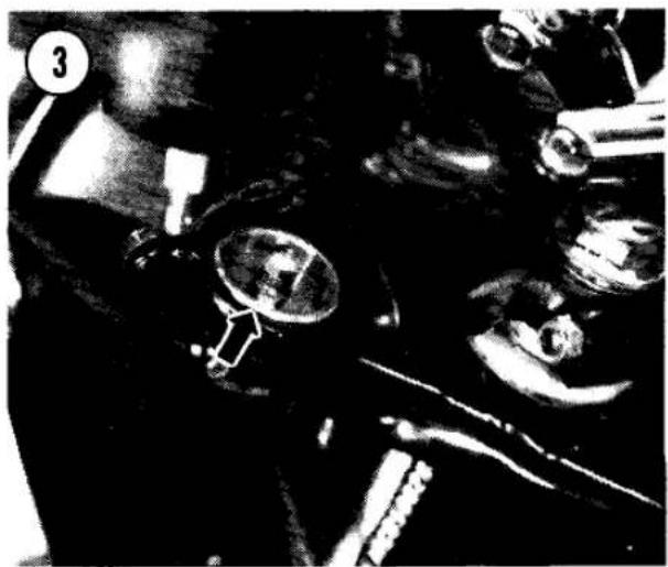
NOTE
The fork bottom Allen bolt is secured with a locking agent and can be hard to remove. After the Allen bolt is loosened, it may not come out because the damper rod base it screws into may turn with the bolt. If a heavy duty air powered impact wrench is available, try that first. If necessary, you may be able to keep the damper rod base from turning by temporarily installing the fork spring and cap, and having an assistant compress the fork while you remove the bottom bolt. If these methods are not successful, you will have to keep the damper rod from turning with a special tool on the end of several socket extensions. Your Kawasaki dealer has a special tool (Figure 9), or you may find that a bolt with a 19 mm head (welded to a long rod) will fit the end of the damper rod.
-
Slide the dust cap up off of the fork slider and check for the presence of an oil seal retaining clip with notches on the inside (Figure 10). If such a retainer is present, it must be removed now with circlip pliers (Figure 11). If the oil seal retainer is a smooth wire circlip with several indentations (Figure 12), the clip does not have to be removed until after the fork tube is removed.
-
Separate the inner fork tube from the slider.
NOTE Models with an oil seal retaining clip with notches on the inside (Figure 10) have 2 anti-friction bushings and a

- Rubber cap
- Circlip
- Top plug
- O-ring
- Fork spring
- Fork tube
- Damper rod
- Piston ring
- Rebound spring
- Damper rod base
- Retainer clip
- Oil seal
- Washer
- Fork slider
- Pinch bolt
- Nut
- Washer
- Drain plug
- Washer
- Allen bolt
- Dust cover
5

FRONT FORK (AIR PRESSURIZED)
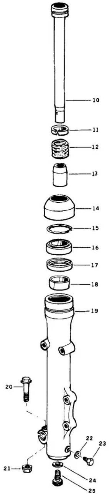
- Rubber cap
- Circlip
- Air valve
- O-ring
- Top plug
- O-ring
- Fork spring
- Fork tube
- Bushing
- Damper rod
- Piston ring
- Rebound spring
- Damper rod base
- Dust cover
- Circlip
- Oil seal
- Spacer
- Bushing
- Slider
- Pinch bolt
- Nut
- Washer
- Drain plug
- Washer
- Allen bolt


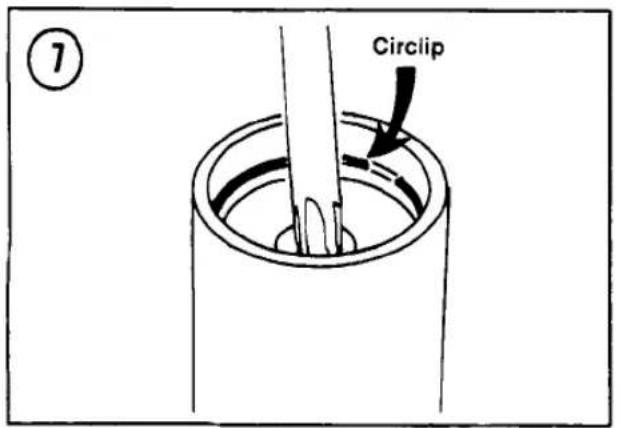

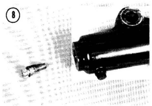


washer (Figure 13) on the end of the fork tube. After removing the clip, you will have to slam the tube and slider apart repeatedly, removing the slider's anti-friction bushing, washer and oil seal from the slider as the tube comes out.
- Remove the damper rod and rebound spring. The damper rod base will probably be at the bottom of the fork slider.
- On models whose oil seal retainer is a smooth wire circlip with several indentations (Figure 12), remove the fork seals by prying the circlip from the top of the slider and then pulling out the oil seals.
NOTE
It may be necessary to slightly heat the area on the slider around the oil seal prior to removal. Be careful not to damage the top of the slider.
Inspection
- Thoroughly clean all parts in solvent and dry. Check the fork tube for signs of wear or scratches that would damage the oil seal.
- Inspect the fork tube and slider anti-friction bushings (Figure 13), if so equipped. Install new bushings if damaged.
- Check the damper rod for straightness (Figure 14). If bent, install a new rod.
- Carefully check the piston ring for wear or damage (Figure 15).
- Inspect the oil seals and dust cap for scoring, nicks and loss of resiliency. Replace if the condition is questionable.
- Check the O-ring on the top plug and install a new one if damaged.
- Check the upper fork tube for straightness. If bent or severely scratched, it should be replaced.
- Check the lower slider for dents or exterior damage that may cause the upper fork tube to drag when riding. Replace it if necessary.
- Measure fork spring free length. Replace the spring if shorter than specified in Table 1. Compare the left and right fork spring measurements. Replace them both if one is much shorter than the other.


Assembly
- See Figure 4 or Figure 5. Put the damper rod spring onto the damper rod and insert them into the top of the fork tube (Figure 14).
- On models with anti-friction bushings, make sure that the slider's bushing, the washer and the oil seal are in place on the fork tube (Figure 16). Install the seal with the numbered or marked face up. The slit in the anti-friction bushing should face the right-hand or left-hand side of the fork slider.
- Insert the damper rod base onto the end of the damper rod (Figure 16).
- Insert the fork tube into the slider. Apply a locking agent such as Loctite Lock N' Seal to the threads of the bottom Allen bolt before installing it with its washer and torque the bolt as specified in Table 2. To keep the damper rod base from turning, use the same method you used during disassembly.
- Tap the oil seal into place until it seats.
NOTE
You may find that a piece of pipe just large enough to slide over the fork tube will seat the oil seal squarely without damaging it (Figure 17). Make sure the seal is not cocked in its hole.
- On models with an oil seal retaining clip with notches on the inside (Figure 10), install the oil seal circlip.
- Install the dust cap.
- Add fresh oil to each fork tube; see Fork Oil Change in Chapter Three.
- Install the fork spring and install the top plug (Figure 18).
NOTE
If one end of the fork spring has more closely wound coils than the other end, install the spring with the closely wound coils at the top.
- Push the top plug into the fork tube and hold it in place while you install the circlip (Figure 19).
- Models with air pressurized forks, pressurize them. See Fork Air Pressure in Chapter Three.
STEERING HEAD
If your periodic checks detect excessive steering play, adjust the steering as described in this section. The steering head should also be disassembled, cleaned, inspected for wear on the balls and races, and lubricated with a waterproof grease according to the maintenance schedule (Table 1, Chapter Three).
Adjustment
- Raise the front wheel off the ground; support the motorcycle securely under the engine.
- Remove the fuel tank to protect its finish. See Fuel Tank Removal in Chapter Seven.
- Loosen both upper fork clamp bolts (Figure 20).
- Loosen the steering stem clamp bolt at the rear of the upper triple clamp (A, Figure 21) and loosen the head bolt (B). You may have to detach the handlebars to loosen the head bolt.
- Back the steering stem adjuster (C, Figure 21) out one or two turns until it feels free, then turn the adjuster back in with a spanner wrench until you just feel the steering play taken up. There is a spanner wrench in the motorcycle's tool kit.
NOTE
Don't back the adjuster out too far or the steering bearing balls may drop down into the steering head. Complete disassembly of the steering is required to put the balls back in place.
- Tighten the adjuster another 1/16 turn.
CAUTION
Don't turn the adjuster so tight that you indent the bearing balls into their races. If you do, the steering will be "notchy" and you'll have to replace the races.
- Torque the steering stem head bolt as specified in Table 2 and tighten the rear clamp bolt.
- Torque the upper fork clamp bolts as specified in Table 2.
- Recheck the steering play as described in Chapter Three. If the play is still incorrect, disassemble and inspect the steering head.


- Install the fuel tank. See Fuel Tank Installation in Chapter Seven.
Disassembly/Assembly
Refer to Figure 22. As you remove parts, note the location of all cable and wiring guides and straps for proper installation during reassembly. Watch what you're doing and make a note of anything you might not remember a week from now in case you have to order parts from your dealer. Pay particular attention to control, wiring and instrument cable routing.
22
STEERING HEAD
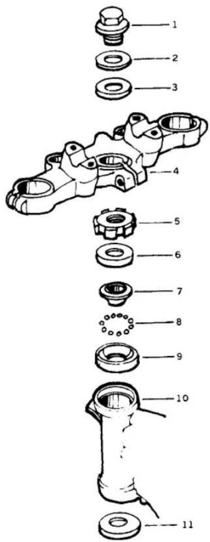

- Head bolt
- Washer
- Wave washer
- Upper triple clamp
- Adjuster
- Cap
- Upper inner race
-
Balls, 1/4 in. (19)
-
Upper outer race
- Steering head
- Lower outer race
- Balls, 1/4 in. (20)
- Lower inner race
- Grease seal
- Washer
-
Lower triple clamp
-
Raise the front wheel off the ground; support the motorcycle securely under the engine.
- Remove the fuel tank to protect its finish. See Fuel Tank Removal in Chapter Seven.
- On the KZ550-D, remove the fairing; see Fairing in this chapter.
- On the KZ550-C and D, remove the bottom headlight shell mounting bolt.
- Remove the headlight from its shell and disconnect the wiring connectors; see Headlight Removal in Chapter Eight. Push the wiring out the back of the shell.
- Remove the turn signals from the headlight shell and remove the headlight shell.
- Disconnect the speedometer and tachometer cables at the meters (Figure 23).
- Remove the trim plate mounting screws and the trim plate from the front of the lower triple clamp.
- Remove the 2 brake junction mounting bolts (Figure 24).
- On the KZ550-C, remove the 2 upper nuts and 1 lower headlight bracket bolt with lockwashers and washers (Figure 25). Pull the headlight bracket and shell assembly free from the steering head.
CAUTION
If you remove the instruments, store the meters right side up. If they are upside down or sideways, the instrument fluids will leak and the meters won't work properly.
- Remove the handlebar clamp bolts (Figure 26) and detach the handlebar assembly. Let it hang down in front of the motorcycle, being careful not to damage any cables or wires.
-
Detach the complete front brake system—master cylinder junction block and caliper(s)—without disconnecting any brake lines.
-
Remove the front wheel. See Front Wheel Removal in Chapter Nine.
-
Remove the front fender.
-
Remove the front forks as described in this chapter.
-
If there are any other parts attached to the fork clamps, remove them now.


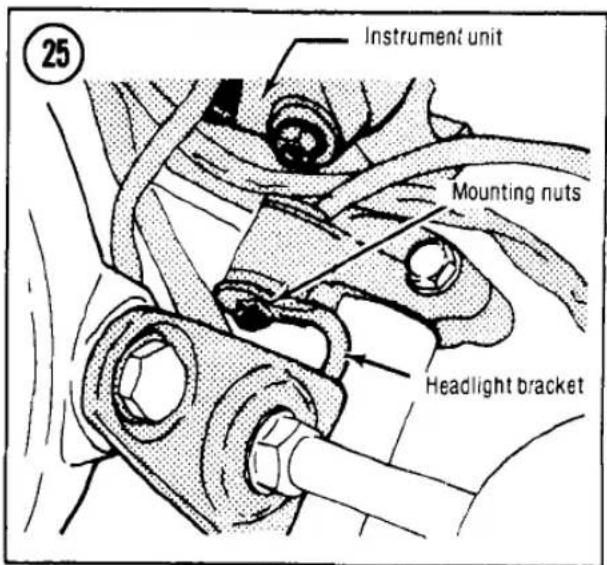


- Loosen the upper triple clamp rear bolt (A, Figure 21), then remove the head bolt (B), washer and lockwasher.
- Remove the upper triple clamp. If necessary, tap it up from the bottom with a soft mallet.
- Hold the lower triple clamp up to keep it from falling and remove the notched steering adjuster nut with a spanner wrench (Figure 27).
- Remove the lower triple clamp and steering stem assembly from the bottom of the steering head (Figure 28).
NOTE
Catch the lower bearing balls as they fall out. Remove any balls stuck in the bottom bearing race (Figure 29).
- Remove the steering stem cap and inner race from the top of the steering head (Figure 30).
- Remove the bearing balls from the steering head, catching any that fall out (Figure 31).
- To assemble, reverse the disassembly procedure. Note the following:
a. Stick the bearing balls in place with grease while you install the lower triple clamp and steering stem. There should be 20 balls (1/4 in. diameter) at the bottom and 19 balls (1/4 in. diameter) at the top.
b. Adjust the steering play after installing the upper race, cap and adjuster; see Steering Head Adjustment in this chapter.
c. Leave the steering top head bolt loose until after you insert and align the fork legs.
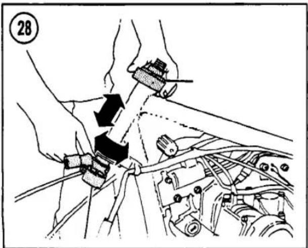
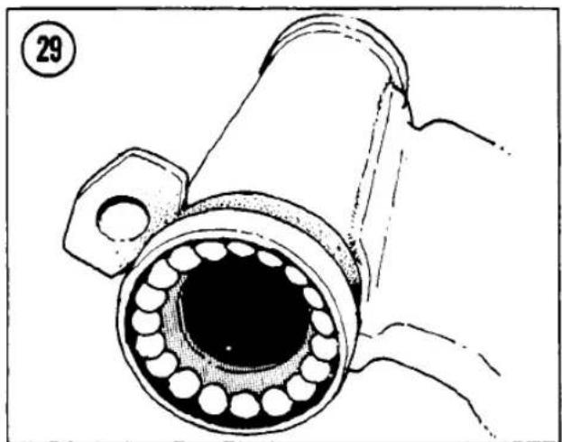
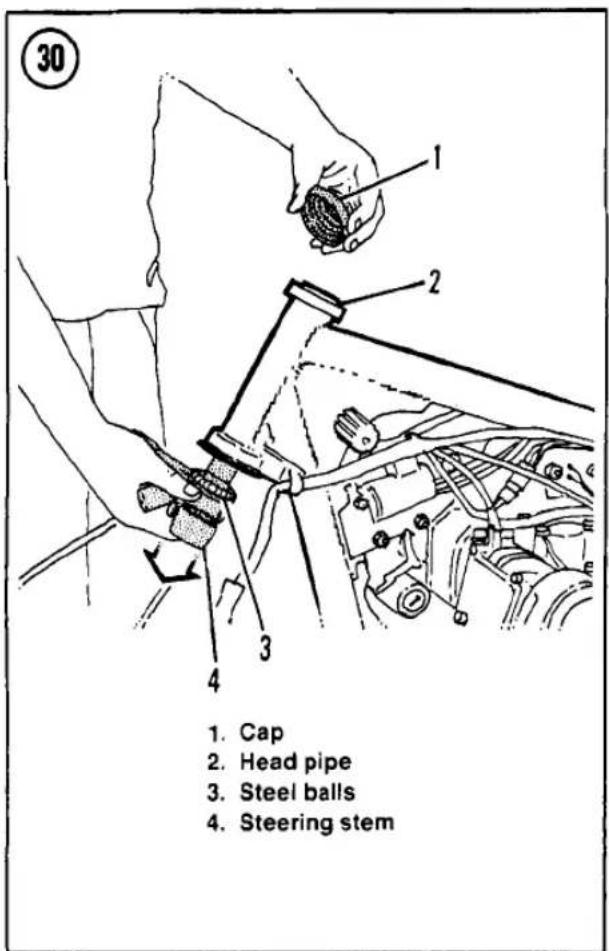
d. Make sure all hoses and cables are routed through their guides (Figure 32 and Figure 33).
e. Torque the fork clamp bolts, steering stem top bolt and handlebar clamp bolts as specified in Table 2.
f. If you replaced any bearings or races, recheck the steering play after a short ride. If the steering is loose, the bearings weren't fully seated during installation; readjust the steering play.
Inspection and Lubrication
-
Clean the bearing races and bearings with solvent.
-
Check for broken welds on the frame around the steering head.
-
Check each of the balls for pitting, scratches or discoloration indicating wear or corrosion. Replace them in upper or lower sets if any are bad.
-
Check the upper and lower races in the steering head. See Bearing Race Replacement


in this chapter if the races are pitted, scratched or worn.
-
Check the upper and lower inner races on the steering stem for pitting, scratches or wear. Replace them if necessary.
-
Check the steering stem for cracks.
-
Grease the bearings and races.


Bearing Race Replacement
The head and steering stem bearing races are pressed into place. Do not remove them unless they are worn and require replacement; ball races are easily bent. Take old races to your dealer to ensure exact replacement.
Steering head races
To remove the steering head races, insert a hardwood stick into the head tube and carefully tap the race out from the inside (Figure 34). Tap all around the race so that neither the race nor the head tube are bent. To install a race, grease it and fit it into the end of the head tube. Tap it slowly and squarely with a block of wood (Figure 35). Make sure it is fully seated. You will notice a distinct change in the hammering sound as the race "bottoms-out."
NOTE
The upper and lower races are different. Be sure that you install them at the proper ends of the head tube.
Steering stem races
To remove the steering stem race, try twisting and pulling it up by hand. If it will not come off, carefully pry it up with a screwdriver, while working around in a circle, prying a little at a time. Be careful not to damage the grease seal under the lower race.
Remove the grease seal and washer from the steering stem and install a new seal before reassembling the steering head.
To install the lower stem race, slide it over the steering stem and tap it down with a piece of hardwood or a pipe of the proper size. Work around in a circle so that the race will not be bent. Make sure it is seated squarely and all the way down.
REAR SHOCK ABSORBERS
Service to the original equipment rear spring/gas shocks is limited to inspection for damage to the damper rod, checking for damping and replacing worn mounting bushings.
Some models have adjustable damping at the rear shocks. The relative damping effect for
different adjuster settings (Figure 36 and Figure 37) is described in Chapter Three.
Removal/Installation
Removal and installation of one shock absorber at a time makes the task easier. The unit that remains will maintain the correct distance between the swing arm and the frame.
- Put the motorcycle up on its centerstand.
-
Loosen the upper shock mounting nuts (A. Figure 38).
-
Remove the passenger grab rail.
-
Remove the nut, lockwasher and flatwashers from the upper shock absorber mount.
-
Remove the bottom bolt and lockwasher (B. Figure 38), then remove the shock absorber.
-
To install, reverse the removal steps. Note the following:
a. Check the rubber shock mounting eye bushings for damage or deterioration and replace them if necessary.
b. Put a flatwasher on either side of the grab rail ends.
c. Torque the mounting nuts/bolts as specified in Table 2.
d. Check to see that the spring preload cam adjuster on each shock is turned to the same notch (Figure 39).
e. Check to see that the damping adjuster on each shock is turned to the same setting (Figure 36 or Figure 37).
Inspection
Grasp the upper mounting eye and repeatedly compress and extend the damper rod to check for damping resistance. Resistance during extension of the rod should be noticeably greater than during compression. Also, the resistance in both directions should be smooth throughout the stroke. If the shock absorber fails on either of these points, it is unsatisfactory and should be replaced. If damping is noticeably different between the two shocks, they should both be replaced.
Visually check the damper rod for bending. If bending is apparent, the unit is unserviceable and should be replaced.
Inspect for shock fluid leakage. If any is present, the shocks should be replaced.


SWING ARM
The swing arm has a sleeve at the pivot, riding inside needle bearings pressed into both ends of the swing arm. The sleeve must be inspected for wear and the needle bearings must be lubricated periodically for long life and good handling. Kawasaki uses an endless drive

chain (no master link) on these models for high strength and reliability. The swing arm must be removed to remove the drive chain.
Inspection
(On The Bike)
- Place the motorcycle on its centerstand.
- Disconnect the shock absorbers at the bottom and swing them up out of the way.
- Grasp the top of the rear wheel and the frame and try to rock the wheel back and forth. If you feel any more then a very slight movement of the swing arm and the pivot bolt is correctly tightened, the swing arm should be removed and inspected.
NOTE
Make sure any motion you feel is not caused by loose or worn wheel bearings.
Removal/Lubrication/Installation
See Figure 40.
- Remove the rear wheel. See Rear Wheel Removal in Chapter Nine.


-
Pivot shaft nut
-
Caps (1979); oil seals (1980 and later)
-
Needle bearings
-
Needle bearings (1979)
-
Grease fitting (1979)
-
Swing arm
-
Pivot sleeve
-
Pivot shaft
-
Bolt (2)
-
Lockwasher (2)
-
Chain adjuster stop (2)
-
On models with a rear disc brake, pull the rear brake hose from its swing arm guides, and tie the caliper up to keep stress off the brake hose.
-
Remove the drive chain guard.
-
Remove the lower shock absorber mounting bolt and lockwasher on both sides.
-
Move the swing arm up and down to check for abnormal friction.
-
Remove the swing arm pivot nut (Figure 41).
-
Push out the pivot shaft and move the swing arm to the rear. There is a cap on either end of the swing arm.
-
Push out the swing arm sleeve with a soft metal rod. Take care not to damage the bearings.
-
Clean the old grease from the needle bearings and sleeve and apply a liberal amount of waterproof grease.
-
To install, reverse the removal steps. Note the following:
a. Be sure to loop the drive chain around the swing arm when installing the swing arm.
b. Torque the swing arm pivot nut and shock absorber bolts as specified in Table 2.
c. When installing the drive chain guard, position it carefully on the swing arm brackets or the guard will rub on the drive chain.
Inspection (Off The Bike)
-
Inspect the needle bearings for discoloration or cracking. Replace them if damaged.
-
To replace the bearings, drive them out with a rod inserted from the opposite end of the swing arm. Install new ones carefully to prevent cocking or damage. Install new gease seals.
CAUTION Do not try to remove the bearings unless you intend to replace them. They will be damaged during removal.

-
Measure the outside diameter (OD) of the swing arm sleeve that rides in the bearings. If the OD is smaller than the limit in Table 1, install a new sleeve.
-
Measure the pivot shaft runout. Roll the shaft across a piece of plate glass and measure any gap with a feeler gauge. If the runout is bigger than the limit in Table 1, install a new pivot shaft.
DRIVE CHAIN
Because the drive chain is endless (has no master link), the swing arm must be removed to remove the drive chain from the motorcycle.
WARNING Kawasaki uses an endless chain on this model for strength and reliability. Do not cut the chain with a chain cutter or install chain with a master link. The chain may fail and rear wheel lockup and an accident could result.
Removal/Installation
-
Remove the swing arm as described in this chapter.
-
Remove the engine sprocket cover: see Sprocket Cover Removal in Chapter Six.
-
Remove the drive chain.
-
To install a chain, reverse this procedure; check the chain for wear and lubricate and adjust it as described in Chapter Three.
Table 1 CHASSIS WEAR LIMITS
| Fork spring minimum free length | |
| KZ550-C (all years) | 23.8 in. (605 mm) |
| 1979-80 (except KZ550-C) | 21.4 in. (543 mm) |
| 1981 (except KZ550-C) | 22.1 in. (562 mm) |
| Swing arm sleeve 0 D | 0.865 in. (21.96 mm) |
| Swing arm pivot runout | 0.006 in. (0.14 mm) |
| (Repair limit) | 0.028 in. (0.7 mm) |
Table 3 CHASSIS TORQUES
| Item | Ft.-lb. | Mkg |
| Brake pedal pivot cap nut | 14.5 | 2.0 |
| Front axle nut | 60 | 8.0 |
| Front axle pinch bolt | 14.5 | 2.0 |
| Fork clamp bolts | 13 | 1.8 |
| Fork air valves | 8.5 | 1.2 |
| Fork bottom Allen bolt | 13 | 1.8 |
| Handlebar clamp bolts | 13 | 1.8 |
| Rear axle nut | 60 | 8.0 |
| Rear sprocket nuts | 30 | 4.0 |
| Shock absorber mounts | 22 | 3.0 |
| Steering head clamp bolt | 13 | 1.8 |
| Steering head top bolt | 35 | 4.5 |
| Steering head adjuster locknut | 22 | 3.0 |
| Swing arm pivot nut | 60 | 8.0 |
| Torque link nuts | 22 | 3.0 |
SUPPLEMENT
1982 AND LATER SERVICE INFORMATION
The following supplement provides additional information for servicing 1982 and later KZ550 and ZX550 models.
The chapter headings in this supplement correspond to those in the main portion of this book. If a chapter is not referenced in this supplement, there are no changes affecting that chapter. Any procedures not given for the 1982 KZ550-H1, the 1983 KZ550-H1, F1 and M1 or the ZX550-A1 and A2 are the same as for the 1981 KZ550-D.
If your bike is covered by this supplement, carefully read the appropriate chapter in the basic book before beginning any work.
CHAPTER THREE
LUBRICATION, MAINTENANCE AND TUNE-UP
MODEL IDENTIFICATION
Table 1 lists the models covered by this supplement.
GENERAL LUBRICATION
Throttle Grip
On KZ550-H1, F1 and M1 models, the lower throttle housing has a peg that fits into a hole in the handlebar. All other models have the peg in the upper housing. See Figure 1.
Speedometer/Tachometer Cables
The KZ550-H1, F1 and M1 models have an electric tachometer with no cable to lubricate.
CLUTCH ADJUSTMENT (KZ550-F1 AND M1)
The clutch cable should have about 1/8 in. (2-3 mm) play at the cable end of the lever before the clutch starts to disengage.
At the hand lever, loosen the locknut (Figure 2) and rotate the adjuster until 1/8 in. (2-3 mm) of free play is obtained (Figure 3).
If sufficient free play cannot be obtained at the hand lever, additional adjustment can be made at the cable length adjuster at the clutch mechanism by loosening the locknuts and turning the adjuster. See Figure 4.
FRONT FORKS
See Table 2 for 1982-on fork oil specifications that differ from 1981 information.
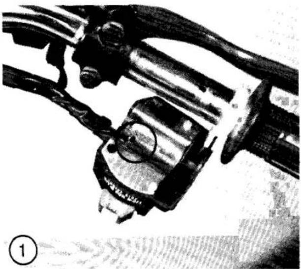
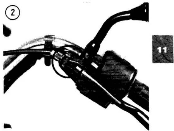
Air Pressure
(KZ550-H1, F1 and M1)
These models are equipped at the factory with an air pressure equalization system for the front forks. The fork leg brackets have internal air passages, sealed by O-rings, that open each fork's air chamber to the connecting hose. There is only one air valve, mounted on the left-hand (KZ550-H1) or right-hand (KZ550-F1, M1) connection bracket. See Figure 5. Air pressure applied to the valve (Figure 6) is distributed equally to the two forks. Table 3 lists air pressure specifications for the front forks.
Oil Change
(KZ550-H1)
On KZ550-H1 models, the handlebar holders must be removed before the fork top plug can be removed. See the Chapter Ten section of this supplement for handlebar holder removal.
Anti-dive Fork Adjustment
(ZX550-A1 and A2)
The front brake/fork assembly is equipped with an anti-dive suspension device. Anti-dive prevents the nosing-down of the front forks during braking. This procedure adjusts the anti-dive device to suit motorcycle riding and load conditions by varying the amount of compression oil pressure in the front forks. The anti-dive mechanism has a 3-position adjustment. Position No. 1 is the weakest and position No. 3 is the strongest.
NOTE
The low position is recommended only for one rider with no accessories.
To adjust the anti-dive unit, perform the following.
- Slide the dust cover off of the bottom of each anti-dive unit.
- Turn the anti-dive adjuster (A, Figure 7) until the desired number is aligned with the arrow on the fork tube (B, Figure 7). Repeat on opposite side.
- Check that the anti-dive adjusters are set on the same number. Install the dust covers.


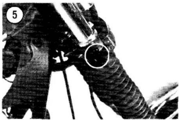
WARNING
A hazardous riding condition may result if the anti-dive units are not adjusted to the same setting on each side.
REAR SHOCK ABSORBER (UNI-TRAK)
The KZ550-H1 is equipped with Kawasaki's Uni-Trak single-shock rear suspension. Suspension adjustment and inspection procedures differ from dual-shock models.


Spring Preload Adjustment
The adjusting sleeve at the top of the rear shock absorber (Figure 8) can be turned to change spring preload.
- Place the motorcycle on the centerstand.
- Remove the left-hand side cover.
- Remove the air cleaner housing mounting bolts and remove the left-hand air cleaner housing.
- Remove the chain cover.
- Using the hook wrench supplied in the motorcycle's tool kit, turn the adjusting sleeve as required. The sleeve can be moved through a vertical range of approximately 0.4 in. (10 mm); see Figure 8:
a. To increase preload, turn the sleeve counterclockwise as viewed from the left-hand side.
b. To decrease preload, turn the sleeve clockwise as viewed from the left-hand side.
- Reverse Steps 1-4; make sure the air cleaner housing is installed properly to avoid air leaks.
Damping Adjustment
The damping adjuster at the bottom of the rear shock absorber has 4 click stops. No. 1 provides the lightest damping and No. 4 provides the heaviest damping.
- Slide the dust cover out of the bottom of the shock absorber spring.
- Turn the damping adjuster (Figure 9) to the desired setting. Be sure it is placed exactly on the click stop.
- Reinstall the dust cover.

Inspection
Refer to the Chapter Ten section of this supplement for Uni-Trak inspection.
REAR SHOCK ABSORBER (KZ550-F1)
KZ550-F1 models are equipped with 4-way, damping adjustable air shocks. Suspension adjustment is different from non-air dual-shock models.
Adjustment
The rear shock absorbers must be adjusted within specifications. One air valve supplies air to both shock absorbers. See Table 4.
- Place the bike on the centerstand to set the rear wheel off the ground.
- Turn the damping adjuster (Figure 10) with your hand to the desired setting (see Table 5).
NOTE Always turn the adjuster until it clicks into position.
- Remove the rear shock air valve cap (Figure 10).
- Attach an air pump to the air fitting.
- Inflate the shocks to about 30 psi. Then slowly bleed off pressure to reach the desired value. Refer to Table 4.
WARNING Never adjust the shocks below the minimum or exceed the maximum allowable air pressure (see Table 4). These conditions can destroy the oil seal and cause loss of control.
- Install the valve cap.
REAR SHOCK ABSORBER (ZX550-A1 AND A2)
Adjustment
The ZX550 shock absorber is provided with 2 adjustments to suit various road and bike load conditions.
Spring adjustment
The spring has a 3-position adjustment. Position No. 1 is the weakest and position No. 3 is the strongest.


NOTE The low position is recommended only for one rider with no accessories.
To adjust the shock absorber spring force, remove the right-hand side cover. Turn the adjuster at the top of the reservoir (Figure 11) to the desired setting.
Damping adjustment
The shock absorber is equipped with a damper adjuster that provides 4 different damping positions: No. 1 (soft) to No. 4 (hard). To adjust, turn the adjuster to the desired position so that the number aligns with the stamped mark on the shock (Figure 12). Refer to Table 5.
NOTE The No. 2 position is recommended for one rider with no accessories.
TIRES
Refer to the tire and load data label on the motorcycle for the correct tire pressure. See Figure 10. Table 6 lists tire sizes for 1982 and later models that differ from 1981 sizes.


On the KZ550-H1, there is no separate pedal height adjustment point. If the pedal is not about 1 in. (20-30 mm) below the top of the footpeg after pedal free play adjustment, make sure the pedal is installed correctly. The punch mark on the pedal must align with the line on the pivot shaft. Remove and reinstall the pedal, if necessary, to correct the alignment. If pedal height is still not correct, the brake pedal may be bent.
Brake Light Switch Adjustment
On the KZ550-H1, you must remove the battery and battery tray to gain access to the brake light switch. Adjustment is the same as for earlier models.
FINAL DRIVE GEAR LUBRICATION (KZ550-F1 AND M1)
Oil Level Check
- Place the bike on the centerstand on a level surface.
- Wipe the area around the filler cap clean and unscrew the cap (A, Figure 13).
- The oil level should be at the case opening hole brim.
- If the oil level is low, refill with the correct gear oil specified in Table 7.
- Install the filler cap and tighten it securely.
Oil Change
The factory recommended oil change intervals are at the first 500 miles (800 km); thereafter every 19,000 miles (30,000 km).
To drain the oil you will need:
a. Drain pan.
b. Funnel.
c. Wrench or socket.
d. One quart of gear oil (refer to Table 7).
1. Ride the bike for a few miles to warm up the oil.
2. Place the bike on the centerstand.
3. Place a drain pan under the final drive gear housing drain plug.
4. Wipe the area around the drain plug clean of all road dirt and remove the drain plug (B, Figure 13). Loosen the filler cap (A, Figure 13) to speed up the flow of oil.
5. Allow the oil to drain for at least 10 minutes.
CAUTION
Do not allow the oil to come in contact with any of the brake components or to drip onto the rear tire.
- Install the drain plug and tighten it securely.
- Refill the case with the recommended type and viscosity of oil. The correct capacity is listed in Table 7.
- Reinstall the filler cap.
ENGINE TUNE-UP
Refer to Table 8 for 1982 and later tune-up specifications that differ from 1981 specifications.
AIR FILTERS
(KZ550-H1)
The KZ550-H1 has two separate air filters. The left-hand element (Figure 14) is a dry paper type element. Once removed, this element can be cleaned as described for 1981 models. The right-hand element (Figure 15) is an oiled foam type and requires a different cleaning procedure.
Removal/Installation
(Paper Element)
- Remove the seat.
- Remove the wing nut and washer (Figure 14) and remove the air filter cover.
- Pull the paper element out of the housing.
- Reverse these steps for installation. Be sure the cover is installed correctly to avoid air leaks.
Removal/Installation
(Foam Element)
- Remove the battery and battery housing.
- Remove the air filter housing mounting screws and remove the housing (Figure 15). Pull the foam element and its frame out of the housing.
- Carefully remove the foam element from the frame.
- After cleaning and oiling the element as described in this section of the supplement, install the element onto the frame.
- Install the element and frame into the housing; make sure the sponge gasket is in place.
- Install the air filter housing; tighten the mounting screws to 43 in.-lb. (0.5 mkg).
- Install the battery housing and battery.
Cleaning/Oiling
(Foam Element)
Kawasaki recommends replacing the foam element after 5 cleanings because the cleaning process enlarges the filter pores. Handle the element carefully and replace it at the first sign of tearing or any other damage.
- Clean the element in solvent to remove old oil and dirt.
- Carefully squeeze the element dry—do not wring it as this will tear the filter.


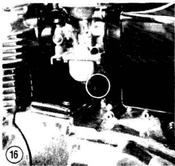

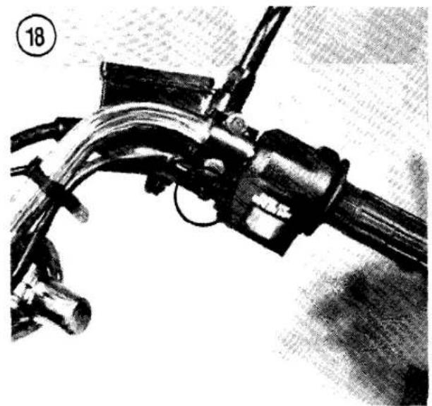
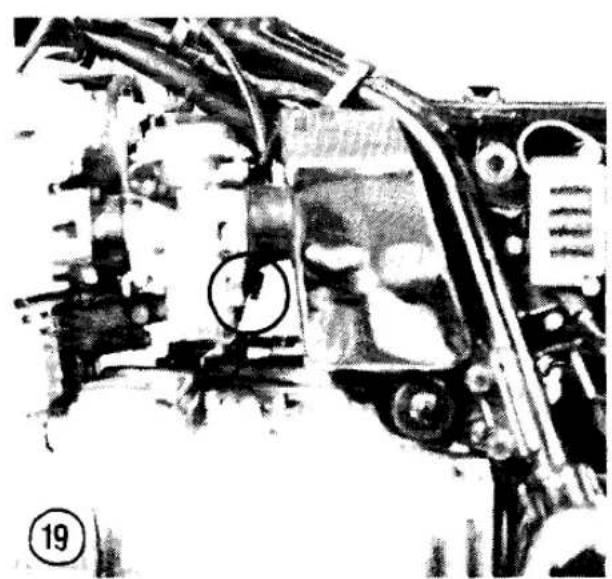
- Soak the element in SAE 30 engine oil. Squeeze out the excess, then wrap the element in a clean, dry rag and squeeze it until it is as dry as possible. Other oils made specifically for foam air filters, such as Bel-Ray Foam Air Filter Oil, may also be used.
FUEL SYSTEM (KZ550-H1, F1 AND M1)
Fuel System Cleaning
On KZ550-H1, F1 and M1 models, there are no overflow tubes attached to the carburetors. You must temporarily attach a gasoline-resistant hose to the fitting at the bottom of the carburetor before opening the drain fitting (Figure 16). Be sure to catch the fluid in a container suitable for gasoline storage. When clean gasoline comes out of the hose, close the fitting and remove the hose.
CARBURETORS (KZ550-H1, F1 AND M1)
Throttle Cable Play
These models have only one throttle cable. Check free play at the throttle grip flange (Figure 17). Kawasaki specifies about 1/8 in. (2-3 mm) of free play. If adjustment is required, loosen the throttle grip cable adjuster locknut (Figure 18) and turn the adjuster as required. Tighten the locknut.
Idle Speed Adjustment
The idle speed adjustment procedure for the KZ550-H1, F1 and M1 models is the same as for earlier models, but the idle speed screw is in a different location (Figure 19).
Synchronizing
Synchronizing the carburetors makes sure that one cylinder doesn't try to run faster than the others, cutting power and gas mileage. The only accurate way to synchronize the carburetors is to use a set of vacuum gauges (a manometer) that measures the intake vacuum of all cylinders at the same time. A typical set of gauges is shown in Chapter One of the main book.

NOTE
Before you try to synchronize the carburetors, make sure all of the following are checked or adjusted first or you won't get accurate readings: air filters, spark plugs, air suction valves (U.S. models), valve clearance, throttle cable play, carburetor holders and clamps air-tight.
- Ride the bike to warm it up fully, set the idle speed, then stop the engine. The correct idle speed is shown on the tune-up decal on the motorcycle (Figure 20) and in Table 8.
- Remove the fuel tank as described in Chapter Seven of the main book. Hook up a temporary fuel supply or use a long fuel line to connect the carburetors to the fuel tank. Plug the vacuum line that goes from the carburetor to the vacuum fuel tap (Figure 21).
WARNING
When supplying fuel by temporary means, make sure the tank is secure and all fuel lines are tight—no leaks.
- Remove the rubber caps or vacuum line from each carburetor's vacuum tap (Figure 22) and attach a set of vacuum gauges following the instrument manufacturer's instructions.
- Turn the fuel tap to PRI, start the engine and check the vacuum readings. The difference between cylinders should be less than 0.80 in. (20 mm Hg). Identical readings are desirable.
- If the difference is greater than specified, loosen the locknut and turn the appropriate synchronizing screw located between the carburetors as required to equalize the vacuum in all cylinders (Figure 23). Kawasaki makes a special tool, part No. 57001-351, which is a combined wrench and screwdriver designed for this job:
a. First match the No. 1 and No. 2 carburetors.
b. Then match the No. 3 and No. 4 carburetors.
c. Finally, match the left-hand pair of carburetors to the right-hand pair.


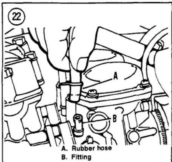

-
Rev the engine once and let it return to idle; check that all cylinders return to equal readings. Readjust, if necessary. Tighten the locknuts while holding the adjuster screws securely. Recheck the readings after tightening the locknuts to make sure the adjusters didn't move; repeat the procedure if necessary.
-
Reset the idle speed (Figure 19), stop the engine and install the vacuum lines and caps.
- Install the fuel tank as described in Chapter Seven of the main book.
Table 1 MODEL YEAR/SUFFIX DESIGNATION
| 1982 | 1983 |
| KZ550-A3 (Standard) | KZ550-F1 (Spectre) |
| KZ550-B4 (European) | KZ550-F2 (LTD) |
| KZ550-C3 (LTD) | KZ550-M1 (LTD Special) |
| 1984 | 1985 |
| ZX550-A1 (GPz) | ZX550-A2 (GPz) |
Table 2 STANDARD FORK OIL*
| Model | Dry CapacityU.S. fl. oz. (cc) | Wet CapacityU.S. fl. oz. (cc) | Oil Levelin. (mm) |
| KZ550-H1 | 7.9 ± 0.1(234 ± 2.5) | 7.2(215) | 19.8 ± 0.1(503 ± 2) |
| KZ550-F1, M1 | 11.05 ± 0.15(327 ± 4) | 9.4(280) | 16.3 ± 0.1(416 ± 2) |
| ZX550-A1, A2 | 7.7 ± 0.08(229 ± 2.5) | ** | 18.58 ± 0.1472 (± 2) |
| * Fork oil level is checked with forks fully extended and the fork spring removed. Use oil grade SAE 5W-20. ** Not specified. | |||
Table 3 FORK AIR PRESSURE*
| Model | Standard | Range |
| KZ550 | ||
| F1, M1 | 7.5 psi (59 kPa) | 7-10 psi (49-69 kPa) |
| H1 | 10.0 psi (70 kPa) | 8.5-11 psi (60-80 kPa) |
| ZX550-A1, A2 | 10.0 psi (70 kPa) | 8.5-11 psi (60-80 kPa) |
| * Never exceed 36 psi (245 kPa) air pressure as it will damage the oil seals. | ||
Table 4 REAR SHOCK AIR PRESSURE (KZ550-F1)*
| Model | Standard | Range |
| KZ550-F1 | 11 psi (78 kPa) | 11-10 psi (78-147 kPa) |
| * Never exceed 71 psi (490 kPa) air pressure as it will damage the oil seals. | ||
Table 5 DAMPING ADJUSTER (KZ550-F1, ZX550-A1)
| Adjuster position | Damping force |
| 1 | Light |
| 2 | Medium |
| 3 | Medium heavy |
| 4 | Heavy |
Table 6 TIRES
| KZ550-H1 (tubeless) | |
| Front | 3.25H-19 4PR |
| Rear | 4.00-18 4PR |
| KZ550-F1, M1 (tubeless) | |
| Front | 100/90-19 57S |
| Rear | 130/90-16 67S |
| ZX550-A1, A2 (tubeless) | |
| Front | 100/90-18 56H |
| Rear | 120/80-18 62H |
Table 7 FINAL DRIVE SPECIFICATIONS (KZ550-F1, M1)
| Item | Specification |
| Oil grade | API GL-5 hypoid gear oil |
| Viscosity | |
| Above 41° F (5°C) | SAE 90 |
| Below 41° F (5°C) | SAE 80 |
| Capacity | 6.4 oz. (190 cc) |
Table 8 TUNE-UP SPECIFICATIONS
| Spark plug type | |
| U.S. | NGK D8EA; ND X24ES-U |
| Non-U.S. | NGK D8ES; ND X24ESR-U |
| idle speed | |
| ZX550-A1, A2 | 1,150-1,250 rpm |
| All other models | 1,000-1,100 rpm |
CHAPTER FOUR
ENGINE


Engine specifications that have changed for 1982 and later models are listed in Tables 9-11.
CAMSHAFT (KZ550-H1, F1 AND M1)
Inspection
Because these models have an electric tachometer, there is no tachometer drive gear on the exhaust camshaft. Service procedures are otherwise identical to earlier models.
CAMSHAFT (ZX550-A1 AND A2)
Installation
Procedures used to install the camshaft sprockets and camshafts remain the same as for 1983 and earlier models, except for the following:
a. Camshaft sprockets have changed for 1984-on ZX550 models. The intake sprocket has six bolt holes (Figure 24) and the exhaust sprocket has four bolt holes (Figure 25); install the sprocket on the camshaft, using the proper holes for each cam.
b. Refer to Figure 26 for new camshaft sprocket alignment. All other installation procedures described in Chapter Four of the basic book remain the same.
ENGINE
Removal (KZ550-H1)
Note the following changes to the engine removal steps given in Chapter Four of the main book:
a. In Step 3, remove the oil level sensor lead at the same time as the alternator and neutral switch leads.
b. In Step 10, the rear brake light switch leads can be simply disconnected; the switch can be left in place.
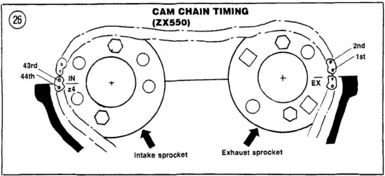
c. In Step 12, remove the ignition coils and exhaust system at the same time as the footpeg.
d. In Step 13B, remove the rear brake pedal completely.
Installation
(KZ550-H1)
Tighten engine mounting bolts as specified in Table 11. In Step 14D of Installation in the main book, the oil level sensor switch lead is blue/red.
Removal
(KZ550-F1 and M1)
When removing the engine assembly, it is first necessary to disconnect the drive shaft from the engine. Refer to Rear Swing Arm Removal/Installation in the Chapter Ten section of this supplement.
Removal/Installation
(ZX550-A1 and A2)
The ZX550 uses rubber mounted engine mounts. During engine installation, lubricate the rubber dampers with soap and water to ease installation into the engine mount brackets. Do not lubricate the rubbers with mineral oil as this will deteriorate them. Install the engine mount damper assemblies as shown in Figure 27. Tighten all engine mount bolts securely.
PISTONS AND RINGS
(ZX550-A1 AND A2)
Installation
After installing the pistons on the connecting rods, apply molybdenum disulfide engine assembly grease to the front and rear of No. 1 and No. 4 piston skirts.
CRANKCASE ASSEMBLY
(ZX550-A1 AND A2)
Installation
During reassembly of the crankcase assembly, apply a light coat of gasket sealer to the upper and lower crankcase halves as indicated in Figure 28.
CAUTION
Do not block any oil passage with sealant.
CRANKSHAFT AND
CONNECTING RODS
(ZX550-A1 AND A2)
Main Bearing
Clearance Measurement
- Disassemble the crankcase as described in Chapter Four of the basic book.
- Make a note of the color on the edge of the bearing insert (Figure 29). The colors are brown, black or green.
- Check the inside and outside surfaces of the bearing inserts for wear, a bluish tint
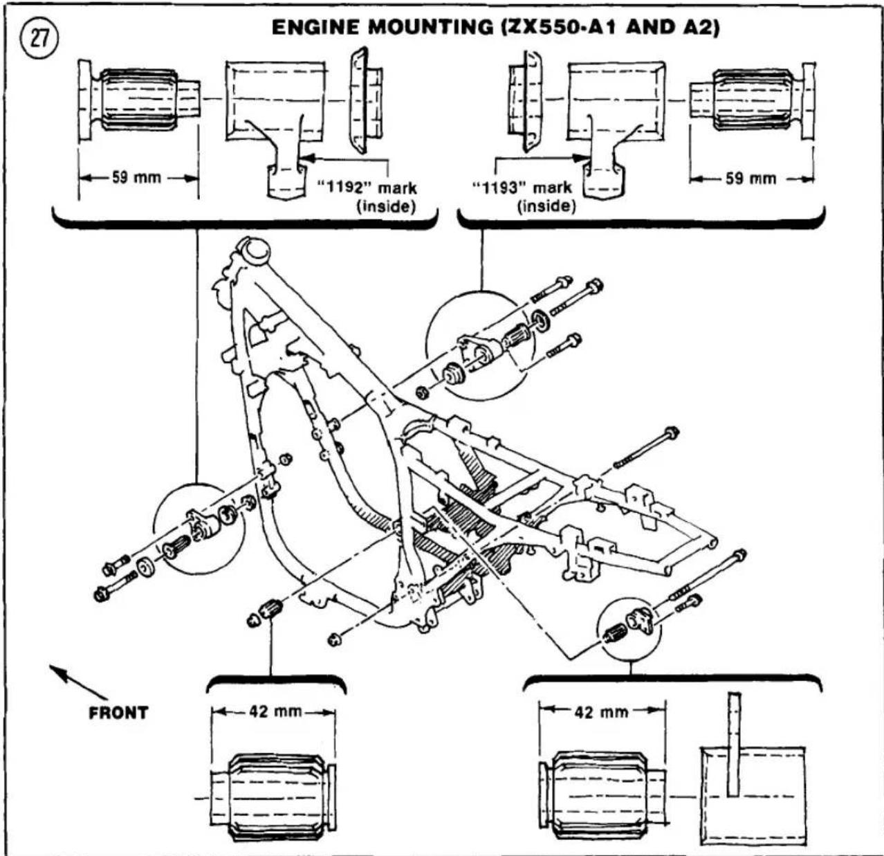
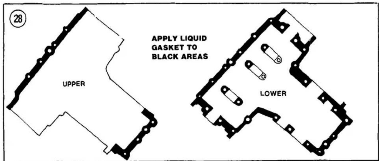

(burned), flaking, abrasion or scoring. If the inserts are good, they may be reused if clearance is satisfactory. If any insert is questionable, replace the entire set.
- Wipe any oil from the crankshaft main journals and the inserts.
- Set the upper crankcase upside down on the workbench. Place it on wood blocks to prevent damage to the cylinder studs.
- Install the main bearing inserts in the upper (Figure 30) and lower (Figure 31) crankcase halves. Make sure their locking tabs are seated in the notches.
NOTE
If the old inserts are reused, be sure they are installed in their original positions to prevent rapid wear.
- Install the crankshaft in the upper crankcase half.
- Place a strip of Plastigage over each main bearing journal parallel to the crankshaft.
NOTE
Do not put Plastigage over the oil holes. Do not rotate the crankshaft while the Plastigage strips are in place.
- Carefully turn the lower crankcase over and install it on the upper crankcase.
- Apply oil to the bolt threads and loosely install the 10 large crankcase bolts (Figure 32).
- Torque the 10 large bolts in 2 stages to 18 ft.-lb. (2.5 mkg). Follow the sequence numbers cast into the bottom of the engine next to the bolts.
- Remove the bolts in the same sequence you tightened them and remove the lower crankcase half.
- Measure the width of the flattened Plastigage according to manufacturer's instructions (Figure 33). The standard crankshaft main bearing clearance is 0.0005-0.0014 in. (0.014-0.038 mm). The maximum service limit is 0.0031 in. (0.08 mm).
- Compare both ends of the Plastigage strip. A difference of 0.001 in. (0.025 mm) or more indicates a tapered journal which should be reground. Confirm with micrometer measurement of the journal OD.

30
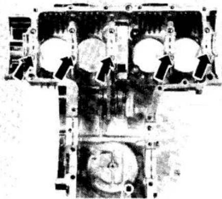
31
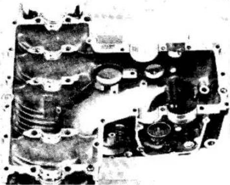
32


-
If the clearance is larger than the service limit, measure the OD of the crankshaft main journal with a micrometer. The minimum main journal OD (service limit) is given in Table 10.
-
If the OD is smaller than the service limit, the crankshaft should be replaced as follows:
a. Check the upper crankcase half at the points indicated in Figure 34 for main bearing bore diameter marks. The crankcase will be marked with an "0" or there will be no mark representing each bearing insert.
b. Purchase a new crankshaft. Then cross-reference the main journal crankshaft diameter markings (Figure 35) with the upper crankcase half marks (Figure 34). Refer to Table 12 to select the new main bearing inserts for the new crankshaft.
- If the OD is larger than the service limit, install new bearing inserts colored green. Always replace all 10 inserts at the same time.
- Recheck the clearance with the new inserts or crankshaft. The clearance should be less than the service limit and as close to standard as possible. See Table 10.
- Clean and oil the main bearing journals and insert faces.
- Install the bearing inserts in the crankcase halves. Make sure their locking tabs are seated in the notches.
NOTE
If the old inserts are reused, be sure they are installed in their original positions for minimum wear.
- Reassemble the engine as described in this supplement and Chapter Four of the main book.
Connecting Rod
Bearing Clearance
- Disassemble the crankcase as described in Chapter Four of the basic book.
- Make a note of the color on the edge of the bearing insert (Figure 29). The colors are brown, black or green.
- Check the inside and outside surfaces of the bearing inserts for wear, a bluish tint (burned), flaking, abrasion or scoring. If the inserts are good, they may be reused if clearance is satisfactory. If any insert is questionable, replace the entire set.
- Wipe any oil from the crankpin journals and the inserts.
- Install the inserts in the connecting rod and cap. Make sure their locking tabs are seated in the notches.
NOTE
If the old inserts are reused, be sure they are installed in their original positions to prevent rapid wear.
- Place a strip of Plastigage on one crankpin parallel to the crankshaft.
NOTE
Do not put Plastigage over the oil holes. Do not rotate the crankshaft while the Plastigage strips are in place.


-
Install the rod cap and torque the nuts to 17.5 ft.-lb. (2.4 mkg).
-
Remove the rod cap.
-
Measure the width of the flattened Plastigage according to manufacturer's instructions (Figure 33). The standard connecting rod big-end bearing clearance is 0.0012-0.0023 in. (0.031-0.059 mm). The maximum service limit is 0.0039 in. (0.10 mm).
-
Compare both ends of the Plastigage strip. A difference of 0.001 in. (0.025 mm) or more indicates a tapered journal (which should be reground) or a bent or twisted rod. Confirm with micrometer measurement of the journal OD.
-
If the clearance is larger than the service limit, measure the OD of the crankpin journal with a micrometer. The minimum crankpin journal OD (service limit) is 1.298 in. (32.97 mm).
-
If the OD is smaller than the service limit, the crankshaft should be replaced as follows:
a. Check the connecting rod at the points indicated in Figure 34 for the big end bore diameter mark. The connecting rod will be marked with an "0" or there will be no mark.
b. Purchase a new crankshaft. Then cross-reference the crankpin diameter markings (Figure 35) with the upper connecting rod marks (Figure 34). Refer to Table 13 to select new connecting rod bearing inserts.
- If the OD is larger than the service limit, install new bearing inserts colored green. Always replace all 8 inserts at the same time.
-
Recheck the clearance with the new inserts or crankshaft. The clearance should be less than the service limit and as close to standard as possible.
-
Repeat for each connecting rod.
-
Clean and oil the crankpin journals and bearing insert faces.
-
Install the bearing inserts in each connecting rod and cap. Make sure their locking tabs are seated in the notches.
NOTE If the old inserts are reused, be sure they are installed in their original positions for minimum wear.
- Reassemble the engine as described in this supplement and in Chapter Four of the main book.
Table 9 ENGINE WEAR LIMITS (KZ550-F1, M1)
| Item | in. | mm |
| Cam chain (20 link length) | 5.07 | 128.9 |
| Camshaft journal/bearing | ||
| cap clearance | 0.008 | 0.22 |
| Camshaft bearing ID | 0.869 | 22.08 |
| Camshaft journal OD | 0.860 | 22.86 |
| Crankshaft main journal/bearing clearance | ||
| Limit | 0.003 | 0.08 |
| Standard | 0.0005-0.0014 | 0.014-0.038 |
| Crankshaft bearing insert thickness | ||
| Brown | 0.0785 | 1.993 |
| Black | 0.0786 | 1.997 |
| Blue | 0.0787 | 2.001 |
| Crankshaft side clearance | 0.015 | 0.40 |
| Piston OD | 2.277 | 57.83 |
| Piston pin hole ID | Not specified | |
| Piston pin OD | Not specified | |
| Piston ring/groove clearance | ||
| Top | 0.006 | 0.15 |
| Second | 0.007 | 0.18 |
| Piston ring groove width | ||
| Top | 0.051 | 1.31 |
| Second | 0.052 | 1.33 |
| Oil | 0.102 | 2.61 |
| Piston ring installed gap | ||
| Top and second | 0.024 | 0.6 |
| Valve stem OD | ||
| Intake | 0.215 | 5.46 |
| Exhaust | 0.214 | 5.44 |
| Valve guide clearance (rocking method) | ||
| Intake | 0.008 | 0.22 |
| Exhaust | 0.010 | 0.27 |
| Valve head thickness | ||
| Intake | 0.020 | 0.5 |
| Exhaust | 0.027 | 0.7 |
| Valve seat angles | 32°, 45°, 60° | |
| Valve stem installed height (max.) | ||
| Intake | 1.457 | 37.01 |
| Exhaust | 1.455 | 36.96 |
Table 10 ENGINE WEAR LIMITS (ZX500-A1 AND A2)
| Item | in. | mm |
| Cam lobe height | 1.423 | 36.15 |
| Cylinder bore diameter | 2.287 | 55.10 |
| Piston diameter | 2.276 | 57.83 |
| Piston ring/groove clearance | ||
| Top and second | 0.006 | 0.16 |
| Piston ring groove width | ||
| Top and second | 0.051 | 1.31 |
| Oil | 0.102 | 2.61 |
| (continued) | ||
| Crankshaft main bearing clearance | 0.0031 | 0.08 |
| Crankshaft main bearing diameter | 1.2582 | 31.96 |
| Crankshaft main journal diameter marks | ||
| No mark | 1.2592-1.2595 | 31.984-31.992 |
| “1” mark | 1.2595-1.2598 | 31.992-32.000 |
| Connecting rod bearing clearance | 0.0039 | 0.10 |
| Crankpin diameter | 1.2980 | 32.97 |
| Crankpin diameter marks | ||
| No mark | 1.2985-1.2989 | 32.984-32.994 |
| “O” mark | 1.2989-1.2992 | 32.994-33.000 |
Table 11 ENGINE TORQUES
| Item | ft.-lb. | mkg |
| Clutch spring bolts | 78 in.-lb. | 0.9 |
| Engine mounting bolts | ||
| KZ550-H1, F1, M1 | 25 | 3.5 |
| ZX550-A1, A2 | 29 | 4.0 |
| Oil drain plug | ||
| KZ550-F1, M1 | 22 | 3.0 |
Table 12 MAIN BEARING INSERT SELECTION (ZX550-A1 AND A2)
| Crankcase marking | ||
| 0 | No mark | |
| Crankshaft marking | ||
| 1 | Brown | Black |
| No mark | Black | Green |
Table 13 CONNECTING ROD BEARING INSERT SELECTION (ZX550-A1 AND A2)
| Crankcase marking | ||
| 0 | No mark | |
| Crankshaft marking | ||
| 0 | Black | Brown |
| No mark | Green | Black |
CHAPTER FIVE
CLUTCH


Clutch wear limits for the KZ550-F1 and M1 models that differ from 1982 and earlier models are found in Table 11.
CLUTCH RELEASE MECHANISM (KZ550-F1 AND M1)
Removal/Installation
-
Loosen the clutch cable adjusters at the handlebar (Figure 36) and at the engine (Figure 37).
-
Disconnect the clutch cable at the engine.
-
Turn the clutch release lever counterclockwise and pull it up and out of the crankcase.
-
Examine the clutch release lever for signs of wear and damage. Replace it if necessary.
-
Before installation, replace the O-ring on the bottom of the clutch release lever.
-
Install the clutch release lever into the crankcase as shown in Figure 37. Be sure a clearance of about 1/8 in. (2-3 mm) is maintained between the clutch release lever and the top of the clutch cover when the lever is turned completely clockwise.
-
Attach the clutch cable to the clutch release lever. Adjust the clutch cable as described in the Chapter Three section of this supplement.
CLUTCH RELEASE MECHANISM (ZX550-A1 AND A2)
The clutch release mechanism has been changed on the ZX550. To remove the unit, disconnect the clutch cable at the engine. Turn the release lever counterclockwise and pull the lever out of the clutch cover. To install, insert the release lever into the clutch cover so that the arm is at an 80 degree angle to the clutch cable as shown in Figure 38. Install the clutch cable and adjust it as described in the Chapter Three section of this supplement. After installation, check the clearance between the clutch release lever and the top of the clutch cover when the lever is turned clockwise. The clearance should be 3/32-1/8 in. (2-3 mm). If not, remove the clutch release lever and reinstall.
CLUTCH (KZ550-F1 AND M1)
Inspection
Kawasaki now specifies a clutch spring measurement for these models. The spring tension measurement method used on KZ550-H1 and all 1982 and earlier models is not used. Clutch springs are measured on KZ550-F1 and M1 models with a vernier caliper as shown in Figure 39. Replace the springs that are too short (Table 14); it's a good idea to replace all springs as a set to maintain top performance.

Table 14 CLUTCH WEAR LIMITS (KZ550-F1, M1)
| Item | in. | mm |
| Clutch spring free length | 1.248 in. | 31.7 |
CHAPTER SIX
TRANSMISSION
Transmission specifications for the KZ550-F1 and M1 models that differ from 1982 and earlier models are found in Table 15.
Table 15 TRANSMISSION WEAR LIMITS (KZ550-F1, M1)
| Item | in. | mm |
| Gear fork groove width | 0.209 | 5.3 |
| Shift fork pin diameter | ||
| Shift forks 1-3, 2-4 | 0.307 | 7.8 |
| Shift forks 5-6 | 0.311 | 7.9 |
| Shift drum groove width | 0.327 | 8.3 |
CHAPTER SEVEN FUEL AND EXHAUST SYSTEMS
New carburetor specifications for the KZ550-H1 and KZ550-F1 and M1 models are found in Table 16 and Table 17. Carburetor specifications for the ZX550-A1 and A2 are found in Table 18. These models use constant-velocity type carburetors as explained in the following paragraphs.
CARBURETOR OPERATION (CONSTANT-VELOCITY TYPE)
The following paragraphs explain the basic operation of carburetors, which may be helpful in troubleshooting a problem you suspect is caused by carburetion. If you are disassembling a carburetor, go on to Carburetor Service in this section of the supplement.
The constant-velocity carburetor has a rotating butterfly throttle valve and an engine vacuum-controlled sliding valve that carries the jet needle. This type of carburetor is less susceptible than some caburetors to a stall in acceleration when the throttle is snapped open, because the vacuum slide will not rise until gradually increasing engine vacuum pulls it up. The constant-velocity carburetor is also not as sensitive to changes in altitude as some carburetors are.
Vacuum Slide
The vacuum slide position is controlled by a diaphragm that has engine vacuum on top and atmospheric pressure on the bottom. The slide moves up and down with engine vacuum; any change in atmospheric pressure (such as a change in altitude) also moderates the slide position slightly to maintain a constant air-fuel ratio. The vacuum slide affects the fuel mixture from 1/4 to 3/4 throttle.
Pilot and Primary Main Fuel Systems
NOTE This description describes carburetor operation at a steady speed. When
accelerating, the vacuum slide lags behind the throttle valve.
The carburetor's purpose is to supply and atomize fuel and mix it in correct proportions with air that is drawn in through the air intake. At primary throttle openings (from idle to 1/8 throttle), a small amount of fuel is siphoned through the pilot jet by suction from the incoming air. As the throttle is opened further (from 1/4 to 1/2 throttle), the vacuum slide begins to rise and the air stream also begins to siphon fuel through the primary main jet. From 1/2 to 3/4 throttle, the vacuum slide continues to rise and fuel also siphons through the needle jet. The tapered needle allows the needle jet to flow more fuel as the needle rises with the vacuum slide. From 3/4 to full throttle, the vacuum slide is fully open and fuel siphons through the secondary main jet and needle jet. At full throttle, the needle is lifted far enough to permit the secondary main jet to flow at full capacity.
CARBURETOR TROUBLESHOOTING (CONSTANT-VELOCITY TYPE)
Diagnosing the Problem
In addition to the items listed in the main book, if the engine won't rev to high rpm, check for a hole in the vacuum diaphragm.
CARBURETOR VARIABLES (CONSTANT-VELOCITY TYPE)
The following parts of the carburetor can be changed to alter the fuel mixture. Each part has the most effect over a narrow range of throttle openings, but each also has a lesser effect over a broader range of throttle openings.
Pilot Jet and Screw
The pilot jet and idle mixture setting affect mixture from 0 to about 1/8 throttle. As pilot jet numbers increase, the fuel mixture gets richer. As the idle mixture (pilot air) screw is opened (turned out), the mixture gets leaner.
On U.S. models, the idle mixture screw is sealed under a plug.
Primary Main Jet
The primary main jet affects the mixture from 1/4 to 1/2 throttle. Larger numbers provide a richer mixture, smaller numbers a leaner mixture.
Jet Needle
The jet needle affects the mixture from 1/2 to 3/4 throttle. Constant-velocity type carburetors have only one fixed needle position. The only alteration possible is through substitution of a different needle number or by raising the needle by putting a washer under it; as the needle is raised, the mixture gets richer.
Needle Jet
Only one size needle jet is available on KZ550-H1 and F1, and ZX550-A1 and A2 motorcycles.
Secondary Main Jet
The secondary main jet controls the mixture at full throttle and has some effect at lesser throttle openings. Each jet is stamped with a number. Larger numbers provide a richer mixture, smaller numbers a leaner mixture.
NOTE
Kawasaki uses Reverse type secondary main jets, which have a round head. Do not substitute hex head Mikuni or Amal jets. The numbering systems are not equivalent; a given jet number will flow different amounts of fuel.
CARBURETOR SERVICE
There is no set rule regarding frequency of carburetor overhaul. A motorcycle used strictly for street riding may go 30,000 miles or more without needing a carburetor overhaul. Operation in dusty areas or poor air cleaner maintenance may shorten the useful life of the carburetor.
Removal/Installation
Remove all 4 carburetors as an assembled unit. Replacement of an individual carburetor

is described under Separation in this section of the supplement.
- Put the bike on its centerstand.
- Remove the fuel tank as described in Chapter Seven of the main book.
- Loosen the 4 carburetor holder clamps (Figure 40).
- Slide the 4 spring bands on the air cleaner ducts out of the way.
- Remove the rubber hose(s) from the vacuum fittings(s).
- On U.S. models, pull the vacuum hose from the air cleaner housing.
- Remove the carburetor assembly by moving it up and out to the right.
- Remove the throttle cable lower end from the carburetor bracket.
- To install, reverse the removal steps. Note the following:
a. If any of the carburetor holders are cracked or otherwise damaged, replace them. Use Loctite Lock N' Seal on the Allen bolts and tighten them to 11 ft.-lb. (1.5 mkg).
CAUTION
Make sure there are no air leaks where the carburetors join with the rubber holders. You should be able to feel the carburetors bottom out in the holders on both sides. Any leakage here will cause a lean fuel mixture and engine damage.
b. Route the throttle cable between the steering head and the right fork tube. The cable must not be twisted, kinked or pinched.
c. On U.S. models, connect the two vacuum hoses from the vacuum switching valve to the No. 1 and No. 4 carburetors.
d. Connect the fuel tap vacuum hose to the No. 3 carburetor.
e. Adjust the throttle cable and carburetors as described in the Chapter Three section of this supplement and Chapter Three of the main book.
Disassembly/Assembly
Refer to Figure 41 (KZ550-H1 and ZX550-A1 and A2) or Figure 42 and Figure 43 (KZ550-F1 and M1). Most carburetor disassembly can be done without separating an individual carburetor from the assembly. We recommend disassembling only one carburetor at a time to prevent accidental interchange of parts.
- Remove the diaphragm cover screws and the cover and spring.
- Pull out the slide and diaphragm assembly. Be careful not to tear or puncture the diaphragm.
- To remove the needle from the slide, unscrew the retainer and push the needle out.
- Remove the float bowl screws, lockwashers, float bowl and large O-ring.
5A. KZ550-H1 and ZX550: Pull out the plug and O-ring and unscrew the pilot jet.
5B. KZ550-F1 and M1: Remove the pilot jet. - On KZ550-H1 and ZX550 models, remove the following:
a. Primary main jet.
b. Secondary main jet.
c. Secondary bleed pipe.
7A. KZ550-H1 and ZX550: Push on the top of the needle jet and primary bleed pipe to remove them.
7B. KZ550-F1 and M1: Remove the main jet, bleed pipe and needle jet.
- Push out the float pivot pin and remove the float assembly.
- Remove the screw securing the float valve assembly and remove the valve needle, valve seat, O-ring and filter.
10A. To remove the pilot (idle mixture) screw on U.S. models, carefully remove the plug covering the screw using an awl or similar tool. Turn the screw in until it seats lightly; note the number of turns required. Remove the screw, spring and O-ring.
10B. To remove the pilot (idle mixture) screw on non-U.S. models, simply unscrew it.
11. Unscrew the plunger cap and pull out the starter plunger.
12. Perform Cleaning and Inspection.
13. To assemble, reverse these steps. Note the following:
a. On U.S. models, to install the pilot (idle mixture) screw, turn it in until it seats lightly. Then turn it out the same number of turns noted during disassembly. Install a new plug and seat the edges with silicone sealant; use the smallest amount of sealant possible so that none will find its way into the carburetor.
b. Install the vacuum diaphragm with the tab aligned with the notch in the carburetor body. Fit the diaphragm sealing lip into the carburetor body groove. Lift the slide a little to take stress off the diaphragm as you tighten the cover screws. Then check that the slide moves up and down freely.
c. Tighten the jets securely, but be careful not to strip their threads. Always use the correct size screwdriver to prevent damaging the head of the jet.
d. After assembly, turn the carburetor upside down and listen to be sure the floats are moving freely.
e. Perform Fuel Level Inspection and Carburetor Adjustment as described in this supplement and in Chapter Three of the main book.
Separation
See Figure 41 (KZ550-H1 and ZX550-A1 and A2) or Figure 42 (KZ550-F1 and M1).
- Remove the screws securing the throttle cable bracket and remove the bracket.
- Take the 4 circlips off of the choke shaft and pull out the shaft. A steel ball and spring will fall off the No. 3 carburetor.
41
CARBURETOR (KZ550-H1; ZX550-A1 AND A-2)

- Choke shaft
- Plug
- Steel ball
- Spring
- Locknut
- Balance adjusting screw
- Spring
- Washer
- Circlip
- Starter plunger lever
- Spring
- Cable bracket
- Cover
- Spring
- Stop
- Clip
- Jet needle
- Vacuum slide and diaphragm assembly
- Plug (U.S. only)
- Pilot screw
- O-ring
- Spring
- Dust seal
- Plunger cap
- O-ring
- Starter plunger
- Needle jet
- Primary bleed pipe
- Pilot jet
- O-ring
- Secondary bleed pipe
- Plug
- Primary main jet
- Secondary main jet
- Float
- O-ring
- O-ring
- O-ring
- Valve seat
- Screw
- Valve needle
- Float pin
- O-ring
- Float bowl
- Upper mounting plate
- Lower mounting plate
- Spring
- Washer
- Bushing
- Idle adjusting screw
42

- Choke shaft
- Starter plunger lever
- Bushing
- Spring
- Steel ball
- Circlip
- Spring
- Lower mounting plate
- Spring
- Washer
- Bushing
- Idle adjusting screw
- Vent hose
- Rubber cap
- Cable bracket
- Vacuum hose
- O-ring
- 3-way joint
- O-ring
- Joint
- 3-way joint
- Fuel hose
- Locknut
- Balance adjusting screw
- Spring
- Washer
- Upper mounting plate
- Carburetor

-
Remove the screws securing the mounting plates to the carburetors and remove the plates.
-
Separate the 4 carburetors.
-
To assemble, reverse these steps. Note the following:
a. The centerlines of the carburetor bores must be parallel both vertically and
CARBURETOR (KZ550-F1 AND M1)
- Screw
- Cover
- Spring
- Stop
- Clip
- Jet needle
- Vacuum slide and diaphragm assembly
- Plug (U.S. models only)
- Pilot screw
- O-ring
- Spring
- Starter plunger
- Plunger cap
- Dust seal
- Pilot jet
- Needle jet
- Bleed pipe (primary)
- Main jet
- Filter
- O-ring
- Valve seat
- Valve needle
- Float pin
- Float
- O-ring
- O-ring
- Float bowl
- O-ring
- Drain plug
43
horizontally. If necessary, loosen the mounting plate screws, place the carburetor assembly on a flat surface, align the bores and tighten the screws.
b. To install the choke shaft, grease the shaft positioning spring and ball and insert them into the No. 3 lever. Lightly grease the choke shaft hole in the

carburetor bodies and insert the shaft through each plunger lever and spring. Install the 4 circlips onto the choke shaft.
c. Check that the choke shaft operates properly. It should slide from left to right smoothly, without excessive resistance. When the shaft is pushed to the off position, the plunger lever springs must be compressed slightly to push the plungers against their seat.
CAUTION
If the plunger levers do not seat properly, the air-fuel mixture will be incorrect. Engine damage could result.
d. Visually synchronize the throttle valve plates so that they each have an equal gap at the throttle bore when closed. If necessary, loosen the adjuster locknuts, turn the adjusters as required and tighten the locknuts.
Cleaning and Inspection
- Thoroughly clean and dry all parts. If a special carburetor cleaning solution is used, all non-metal parts must be removed (gaskets, O-rings, plastic plugs, etc.).
- Blow out all the passages and jets with compressed air. Don't use wire to clean any of the orifices; they will be damaged and the carburetor may be ruined.
- Check the cone of the float needle (Figure 44) and replace if it is scored or pitted.
-
Examine the end of the pilot (idle mixture) screw for grooves or roughness. Replace it if damaged.
-
Check all O-rings and plastic plugs for damage and replace as necessary.
- Inspect the vacuum diaphragm for pin-holes or other damage. Replace, if necessary.
FUEL TANK (ZX550-A1 AND A2)
When removing the fuel tank on ZX550 models with the evaporative emission control system, disconnect the breather and return hose at the fuel tank. Plug the return hose with a golf tee. These steps will prevent gasoline from flowing out of the fuel tank.
EVAPORATIVE EMISSION CONTROL SYSTEM (ZX550-A1 AND A2)
All 1984-on ZX550 models sold in California are equipped with a evaporative emission control system to conform with state and government emission requirements. The system is shown in Figure 45. The evaporative emission control system routes fuel vapors from the fuel system into the engine (during operation) and then stores the vapors in a special canister when the engine is stopped.
Inspection
While no adjustments are required to maintain the evaporative emission control system, all hoses and parts should be inspected every 3,000 miles for loose or damaged parts. Repair or replace parts as required.
CAUTION If solvent, gasoline or water enters the canister, the canister's vapor absorbing capacity is reduced and it must be replaced.

If the liquid/vapor separator is removed from its mounting position, do not lay the separator on its side; always place it in its upright mounting position.

45
Table 16 CARBURETOR SPECIFICATIONS (KZ550-H1)
| Item | U.S. | Other |
| Size/type | K26V-1A | K26V-1B |
| Main jet | ||
| Primary | No. 64 | No. 64 |
| Secondary | No. 86 | No. 86 |
| Main air jet | ||
| Primary | 1.30 | 1.30 |
| Secondary | 1.0 | 1.0 |
| Pilot jet | No. 32 | No. 32 |
| Pilot air jet | 1.30 | 1.30 |
| Fuel level | 6 ± 1 mm | 6 ± 1 mm |
Table 17 CARBURETOR SPECIFICATIONS (KZ550-F1, M1)
| U.S. | Other | |
| Size/type | TK, K26V | TK, K26V |
| Main jet | 120 | 120 |
| Pilot jet | No. 32 | No. 32 |
| Jet needle clip position | 4A02 | 4A00 |
| — | 2nd from top | |
| Fuel level | 7 ± 1 mm | 7 ± 1 mm |
| Float height | 27 mm | 27 mm |
Table 18 CARBURETOR SPECIFICATIONS (ZX500-A1 AND A2)
| Size/type | TK, K27V |
| Main jet | 114 |
| Main air jet | 1.0 |
| Pilot jet | No. 34 |
| Pilot air jet | 1.25 |
| Jet needle clip position | 4A10 |
| Fixed | |
| Fuel level | 7 ±1 mm |
| Float height | 27 mm |
CHAPTER EIGHT
ELECTRICAL SYSTEMS
Electrical specifications for the KZ550-F1 and M1 models that differ from 1982 and earlier models are found in Table 19.
IC IGNITER (TRANSISTORIZED IGNITION) (ZX550-A1 AND A2)
The ZX550-A1 and A2 ignition system is shown in Figure 46; refer to it when performing procedures in this section.
Troubleshooting
Voltage check
- Remove the right-hand side cover.
- Disconnect the IC igniter connector (Figure 47).
- With a voltmeter set at DC, connect the positive (+) lead to the yellow/red IC igniter circuit wire and the negative lead (-) to the black/yellow wire. The voltmeter should read approximately 12 volts.
-
If the IC igniter failed the test in Step 3, check the main fuse and all ignition and starting system wires and connections. Also check the engine stop switch, side stand switch, ignition switch and the starter lockout switch as described in this supplement. If these parts and systems are okay, check the diode as described in this section.
-
Reconnect the IC igniter connector. Install the right-hand side cover.
Diode check
- Remove the left-hand side cover.
- Disconnect the diode connector (Figure 48).
-
With an ohmmeter set at R×10, measure and record the resistance between the following terminals (Figure 49):
a. Brown/white to yellow/green.
b. Brown/white to brown.
c. Brown/white to light green. -
Reverse the meter polarity (use the opposite probes to make the connections) and repeat the test. There should be more than 10 times as much resistance in one direction as in the other. If any 2 leads show the same resistance in both directions, the diode is faulty and should be replaced.
Resistance check
If the above checks fail to find fault with the IC igniter and all ignition wiring and connectors are in good condition, remove the IC igniter and have a Kawasaki dealer perform a resistance check.


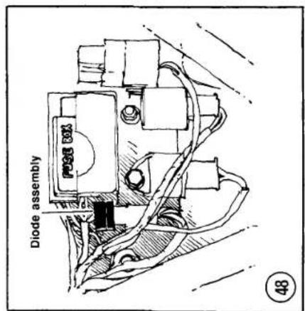

![graph TD A["IGNITION SYSTEM (ZX550-A1 AND A2)"] --> B["Connector"] B --> C["Pickup coil (1 and 4 cylinders)"] B --> D["Timing rotor (2 and 3 cylinders)"] B --> E["Ignition coil (1 and 4 cylinders)"] B --> F["Spark plugs"] B --> G["Engine stop switch"] B --> H["Ignition coil (2 and 3 cylinders)"] B -…](/content/2026/06/1280271/images/5a48b1ae43f3e0e76ed953b7865c2d1e944b98efa48abbeebd605c46bbd88eb8.jpg)
![graph TD A["Main switch"] -->|Y/R| B["Connector"] B -->|Y/R| C["Ignition switch"] B -->|BK/W| D["Starter circuit relay"] D -->|W| E["Fuse"] F["Starter lockout switch"] -->|Y/G| G["Connector"] G -->|LG| H["Neutral switch"] H --> I["Starter motor"] I --> J["Starter relay"] J --> K["Battery"] L["Starte…](/content/2026/06/1280271/images/1bbf1fa59d4c595236d6fa9bfe961b8f84c8aae168d68e68302c975cd92dcc19.jpg)
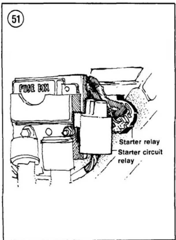
STARTING SYSTEM (ZX550-A1 AND A2)
The starting system for the ZX550-A1 and A2 models is shown in Figure 50; refer to it when performing the procedures in this section.
Starter Relay Testing
- Remove the left-hand side cover.
- Disconnect the starter relay connector (Figure 51).
- With a voltmeter set at DC, connect the positive (+) lead to the black starter relay circuit wire and the negative lead (-) to the black/yellow wire.
- With the ignition switch ON and the transmission in NEUTRAL, push the starter switch and observe the voltmeter. It should read approximately 12 volts.
- If the voltage is incorrect in Step 4, check the main fuse and all starting system wires and connections. Also check the engine stop switch, ignition switch, neutral switch and the

starter lockout switch as described in this supplement. If these parts and systems are okay, check the starter circuit relay as described in this section.
- Reconnect the starter relay connector. Install the left-hand side cover.
Starter Circuit Relay Testing
- Remove the left-hand side cover.
- Disconnect and remove the starter circuit relay (Figure 51).
- Connect an ohmmeter and a 12 volt battery to the starter circuit relay connector as shown in Figure 52.
- Interpret results as follows:
a. With the battery connected, the reading should be 0 ohms.
b. With the battery disconnected, the reading should be infinite.
- If the starter circuit relay failed the tests in Step 4, it should be replaced.
LIGHTING SYSTEM
Front Brake Light
Switch Replacement
The KZ550-H1, F1 and M1 front brake light switch is secured with a single screw (Figure 53). Use Loctite Lock N' Seal on the screw when installing the switch.
Brake Light Failure Switch
The KZ550-C3 and H1 models do not have this switch and warning light circuit. Instead, these models have two dual-filament bulbs for brake/taillights; the bulbs are wired in parallel so that one will continue to burn even if the other is not operating.
FUEL LEVEL SENSOR (KZ550-C3)
An additional solid-state unit in the fuel level warning system automatically turns on the warning light for 3 seconds after the ignition switch is turned ON. If the system does not operate properly, check battery condition and charge and make sure all system wiring connections are clean and tight. If the trouble still exists, troubleshoot as follows.


- If the warning light does not come on for about 3 seconds after the ignition switch is turned on:
a. Replace the bulb.
b. Remove the right-hand side cover and disconnect the 3-pin connector from the self-checking unit. Connect a voltmeter positive lead to the brown wire terminal on the harness side of the connector and the voltmeter negative lead to the black/yellow wire terminal on the harness side of the connector. Turn the ignition switch ON. If the meter does not indicate battery voltage, the wiring harness is defective.
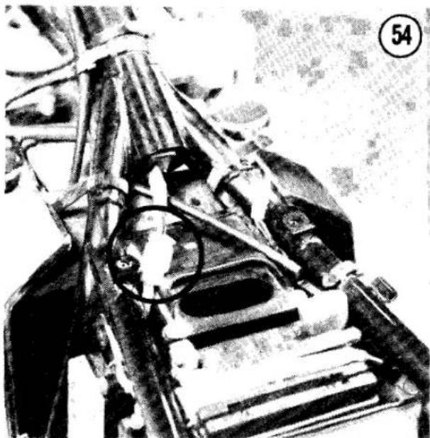
c. If battery voltage is reaching the self-checking unit and the known good bulb still does not light, the self-checking unit is defective and must be replaced.
- If the warning light does not come on when fuel level is known to be low:
a. Make sure the warning light comes on when the ignition switch is first turned ON. If it does not, see Step 1.
b. Disconnect the 2-pin connector from the fuel level sender. Connect a voltmeter positive lead to the green/white wire terminal on the harness side of the connector and the voltmeter negative lead to the black/yellow wire terminal on the harness side of the connector. Turn the ignition switch ON. If the meter does not read battery voltage, the wiring harness is defective. If the meter does read battery voltage, the sender is defective and must be replaced.
- If the warning light stays on when fuel level is known to be high:
a. Remove the right-hand side cover and disconnect the 3-pin connector from the self-checking unit.
b. Turn the ignition ON.
c. If the light still goes on, the fuel level sender is defective and must be replaced.
- If the warning light flickers irregularly:
a. Make sure the fuel level is well above the warning point.
b. Check for worn wires on the warning circuit shorting to the frame or other components.
c. Check the charging system output.
d. If all the items above are normal, unplug the 3-pin connector from the self-checking unit. If the problem disappears, the self-checking unit is defective and must be replaced. If the problem persists with the unit disconnected, check again for wiring shorts. If none are found, the fuel level sender is probably shorting internally and must be replaced.
FUEL AND OIL LEVEL WARNING SYSTEM (KZ550-F1 AND M1)
This system monitors the level of fuel in the fuel tank and the level of oil in the engine. The complete system consists of a fuel level sensor in the fuel tank, an oil level sensor in the engine, two instrument panel warning lights and an electronic self-checker to check for blown bulb filaments.
When the ignition switch is turned ON, the self-checker turns on both warning lights and then turns them off after 2-5 seconds. If a warning light stays on after the checking time, there is a low fuel or oil level. If the system does not operate properly, check battery condition and charge and make sure all system wiring connections are clean and tight. If the trouble still exists, troubleshoot as follows.
- If a warning light does not come on for about 2-5 seconds after the ignition switch is turned ON:
a. Replace the bulb.
b. Raise the seat and disconnect the connector from the self-checking unit (Figure 54). Connect a test wire between the green/white and black/yellow wires (fuel warning system) or between the yellow/blue and blue/red wires (oil warning system). Turn the ignition switch ON. If the warning light does not come on, inspect the wiring leads and

bulb for damage. If these are okay, proceed to Step 2 and check the power supply to the self-checker.
-
Raise the seat and disconnect the self-checking connector as in Step 1. Connect a voltmeter positive lead to the brown wire terminal on the harness side of the connector and the voltmeter negative lead to the black/yellow wire terminal on the harness side of the connector. Turn the ignition switch ON. If the meter does not indicate battery voltage, the wiring harness is defective. If battery voltage is reaching the self-checking unit and the known-good bulb still does not light, the self-checking unit is defective and must be replaced by removing it from the center frame tube (Figure 55).
-
If problems are still experienced with the warning system, check the individual sensor as described in this section. If the sensor checks okay, replace the self-checker.
Fuel level sensor check
- Disconnect the fuel level sensor connector (Figure 56) and remove the fuel tank. Drain it of all fuel. Store the fuel in a certified gasoline storage can or tank.
- Remove the fuel level sensor from the fuel tank and reconnect the sensor to the main wiring.
- Turn the ignition switch ON. The fuel warning light should come on and stay on. Install the fuel tank.
Oil level sensor check
- Drain the engine oil as described in Chapter Three in the main body of this book.
- Remove the oil level sensor from the bottom of the oil pan.
- Set an ohmmeter to×1. Connect one lead to the sensor body. Test as follows:
a. Hold the sensor upright as shown in Figure 57. The ohmmeter should read infinite resistance.
b. Turn the sensor so that it is upside down (Figure 57). The reading should be less than 0.5 ohms.
c. If the oil level sensor failed either test, it is damaged and must be replaced.


- Install the oil level sensor in the oil pan. Refill the engine with oil as described in Chapter Three in the main body of this book.
HAZARD FLASHING SYSTEM (U.S. AND CANADIAN MODELS)
U.S. and Canadian models are equipped with a hazard flashing system that will cause all of the turn signals to flash on and off. A hazard flasher relay that is separate from the turn signal relay supplies current for the circuit. The ignition switch used on these bikes is slightly different from models with no hazard flashing system.
The hazard flashing system can only work properly if the turn signals work properly, so check the turn signal system first if problems arise. Make sure all circuit connections are clean and tight and that no wiring is damaged. If problems persist, test the hazard flashing system components as follows.
- To test the hazard switch, unplug its connector and connect an ohmmeter between each of the 3 switch terminals in turn (3 readings in all). With the switch OFF, there should not be continuity between any of the terminals. With the switch ON, there should be continuity between all terminals. Replace the switch if the readings are not as specified.
- To test the hazard relay, unplug its connector and connect an ohmmeter between its 2 terminals. The reading should be about 60 ohms. If there is less resistance than specified or if there is infinite resistance, replace the relay.
ELECTRONIC TACHOMETER/VOLTMETER (KZ550-H1, F1 AND M1)
These models have an electrically operated tachometer that also operates as a voltmeter when the switch on the meter is depressed. The meter operates on current pulses from the primary winding of one of the ignition coils.
If the ignition system is working properly but the meter does not operate correctly, make sure the meter mounting hardware is secure and that the 4 rubber dampers are in good condition. The mounting hardware is beneath the meter assembly bottom cover. If the problem still exists, remove the fairing, headlight and meter bottom cover and troubleshoot the system as follows. If neither instrument function works or only the voltmeter function works, start at Step 1. If the tachometer function works but the voltmeter function does not, start at Step 3.
- Check that battery voltage is reaching the meter:
a. Connect a voltmeter positive lead to the brown wire terminal or connector (Figure 58) on the back of the meter assembly.
b. Connect the voltmeter negative lead to the black/yellow wire terminal.
c. Turn the ignition ON.
d. If the meter does not read battery voltage, the wiring between the meter and the battery is defective.
- Check that the engine speed signal is reaching the meter:
a. Connect a voltmeter positive lead to the brown wire terminal on the back of the meter assembly.
b. Connect the voltmeter negative lead to the black wire terminal on the back of the meter assembly.
c. Turn the ignition ON without starting the engine. The voltmeter should read zero voltage.

d. Start the engine and note the voltmeter reading. It should be 2-4 volts with the engine running.
e. If the voltmeter readings are not as specified, the wiring between the meter and the ignition coil is defective.
- KZ550-H1 only: Check the meter switch that controls tachometer/voltmeter function:
a. Disconnect the 3 leads from the switch (green, red and yellow).
b. Connect an ohmmeter or test light between the green and red terminals on the switch. With the switch released, there should be continuity (low resistance, test lamp lights). There should be no continuity (infinite resistance, test lamp unlit) when the switch is depressed.
c. Connect the ohmmeter or test lamp between the red and yellow terminals on the switch. With the switch released, there should be no continuity. With the switch depressed, there should be continuity.
d. Connect the ohmmeter or test lamp between the green and yellow terminals on the switch. There should be no continuity at either switch position.
e. If the switch does not perform as described, replace it and repeat the test. If the switch performs as described, the tachometer/voltmeter unit is defective and must be replaced.
SOLID-STATE GAUGE AND WARNING LIGHT PANEL (KZ550-H1)
This computerized instrument panel monitors sidestand position, engine oil level, battery electrolyte level and fuel level. A liquid crystal display (LCD) continuously shows fuel level; other LCDs light up or flash when the computer detects a problem in one of the monitored systems. A red light-emitting diode (LED) flashes when there is a problem in one of the monitored systems.
The LCDs and LED should light when the ignition switch is first turned ON to show that they are operational. If any one of the LCDs or the LED does not light when the ignition switch is first turned ON, yet others are functional, there is an internal fault and the entire instrument panel must be replaced. It cannot be disassembled for repair.
If none of the LCDs or LED light when the ignition is first turned ON, there may be a problem in the bike's wiring harness. Start with Step 1 of the following troubleshooting procedure.
If one or more of the individual warning systems does not work, yet others do, that system's sensor may be defective. Perform the appropriate tests in the following troubleshooting procedure according to what system is at fault.
If these steps do not pinpoint the problem, repeat them (where possible) while riding the bike. The problem may only show up under actual operating conditions. If the sensors all test okay and the bike's wiring is in good condition, replace the instrument panel.
- Make sure that battery voltage is reaching the panel:
a. Disconnect the panel's red, 6-pin connector.
b. Connect a voltmeter positive lead to the brown wire terminal on the harness side of the connector.
c. Connect a voltmeter negative lead to the black/yellow wire terminal on the harness side of the connector.
d. Turn the ignition switch ON. The voltmeter should indicate battery voltage. If it does and none of the panel lights work, replace the panel. If there is no voltage reading or a low reading, check the battery and wiring connections.
- Check the wiring between the panel and the various connectors:
a. Disconnect the panel's red, 6-pin connector.
b. Using a voltmeter and ohmmeter, make the test connections shown in Table 20. Be sure to use the correct test instrument and measurement range.
c. If any of the readings are not as shown in Table 20, repair the wiring between the
red 6-pin connector and the appropriate sensor.
d. If the readings are all as specified, test the individual sensors as described in the following steps.
- To test the sidestand switch:
a. Disconnect the leads at the switch. Connect an ohmmeter (set at×1) between the leads.
b. With the sidestand up, the meter should read zero ohms (no resistance).
c. With the sidestand down, the meter should read infinite resistance.
d. If the switch does not perform as described, make sure it is properly mounted on the frame. If it is properly mounted but the readings are not as specified, replace the switch.
- To test the oil level sensor:
a. Drain the engine oil as described in Chapter Three of the main book and remove the oil level sensor.
b. Connect an ohmmeter (set at×1) between the sensor lead and the sensor body.
c. With the sensor held upright (Figure 57), the ohmmeter should read no continuity (infinite resistance). With the sensor held upside down (Figure 57), the ohmmeter should read less than 0.5 ohms.
d. If the readings are not as specified, replace the oil level sensor.
- To test the battery electrolyte level sensor:
a. Remove the seat and disconnect the pink lead from the sensor.
b. Set a voltmeter at the 10V range. Connect the voltmeter positive lead to the sensor lead; connect the voltmeter negative lead to the frame (chassis ground).
c. The voltmeter should read more than 6 volts. If it reads less, check the battery electrolyte level. Make sure the sensor is installed in the correct battery cell as indicated by the arrow on the battery case. Pull the sensor out of the battery and check it for corrosion or other damage; replace if damage is found.
- To test the fuel level sensor:
a. Remove the fuel tank and remove the sensor from the tank as described in Chapter Seven of the main book.
b. Check that the float operates smoothly and that the tank walls do not interfere with its operation. The float should move downward under its own weight. If not, or if the sensor shows any mechanical damage, replace it.
c. Connect an ohmmeter between the sensor leads. With the float at its highest position (as with a full tank), the ohmmeter should read 1-5 ohms. With the float at its lowest position (as with an empty tank), the ohmmeter should read 103-117 ohms.
d. If the readings are not as specified or if the readings do not change smoothly as the float is moved, replace the sensor.
GAUGE AND WARNING LIGHT SYSTEM (1984-ON ZX550-A1 AND A2)
The gauge and warning light system monitors critical operating circuits on the motorcycle. The system consists of a liquid crystal display (LCD) combined with a red light emitting diode (LED) warning light to monitor the engine oil level, fuel level, battery electrolyte level and sidestand position.
Gauge and Warning System Test
The following test assumes the battery is fully charged. Refer to Figure 59.
-
Remove the fuel tank to gain access to the warning system connector under the fuel tank.
-
Connect a voltmeter to the motorcycle half of the warning system wiring harness as follows:
a. Voltmeter positive (+) lead to the brown wire.
b. Voltmeter negative (-) lead to the black/yellow wire.
- Turn on the ignition switch. The voltmeter must indicate battery voltage. If battery voltage is not present in the warning system wiring harness, check for a bad connection or a broken wire. If battery voltage is present at the connector, continue this procedure.

CAUTION
Take care during the next test steps not to short any wires or connector terminals together or to ground. The warning system gauge unit may be destroyed.
- Prepare 7 jumper wires to connect battery power and simulate the warning sensors.
- Refer to Figure 59 and connect jumper wires as follows to simulate warning circuit connections:
a. Sidestand: Green/white lead to battery negative (-) black/yellow lead.
b. Fuel gauge: White/yellow lead to battery negative (-) black/yellow lead.
c. Oil level: Blue/red lead to battery negative (-) black/yellow lead.
d. Battery electrolyte: Pink lead to battery positive (+) white/red lead.
-
Use 1 jumper wire between the green/yellow wires in each half of the warning unit connector to connect power to the warning unit.
-
When battery power is connected to the warning unit, the self-test procedure should
![graph TD A["1"] --> B["R/BL"] C["1"] --> D["G/Y"] E["2"] --> F["BR"] E --> G["BK/Y"] E --> H["P"] E --> I["G/W"] E --> J["BL/R"] K["3"] --> L["G/W"] K --> M["BL/R"] N["4"] --> O["BK/Y"] N --> P["W/Y"] Q["5"] --> R["BL/R"] S["6"] --> T["R/BL"] U["7"] --> V["R/BL"] W["8"] --> X["BL/R"] Y["9"] --> Z["B…](/content/2026/06/1280271/images/505744db1ca56e40951e5fc4a10d34e06f280c94187c1388b0cc270f71e84924.jpg)
LCD GAUGE AND WIRING SYSTEM (ZX550-A1 AND A2)
- Illuminator lights
- LCD fuel gauge and warning unit
- Connector
- Connector
- Fuel level sensor
- Connector
- Warning lights
-
Oil level sensor
-
Sidestand switch
- Battery
- Battery electrolyte level sensor
- Fuse (10A)
- Fuse (20A)
- Connector
- Ignition switch
GAUGE AND WARNING UNIT DISPLAY (ZX550-A1 AND A2)
- Warning light—not lighted
- Fuel gauge—9 segments lighted
- Side stand warning—not lighted
- Oil level warning—not lighted
- Battery electrolyte warning—not lighted

- Warning light (flashes when any simulating jumper wire is disconnected
- Fuel gauge (white/yellow jumper is disconnected*)
- Side stand warning (green/white jumper is disconnected)
- Oil level warning (blue/red jumper is disconnected)
- Battery electrolyte warning (pink jumper wire is disconnected)
* A time display is included in the fue! gauge circuit. It takes approximately 3-12 seconds for each segment to appear or disappear and 3-7 seconds for the bottom segment to begin or stop flashing.
GAUGE AND WARNING UNIT
DISPLAY (ZX550-A1 AND A2)
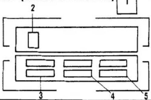
61
62
Engine stop switch
| R | Y/R | |
| OFF | ||
| ON | ○— | ○ |
start. When the self-test is complete the warning unit should appear as shown in Figure 60. If the self-test did not start or if any malfunction exists in the display, the warning unit is defective and must be replaced by a Kawasaki dealer.
- One by one disconnect the jumper wires simulating the warning circuits (Step 5). The LCD warning light should flash and the warning display should flash for each simulated malfunction. See Figure 61.
- If the warning and gauge unit tests good but a malfunction still exists when the unit is connected to the motorcycle wiring harness, a fault may exist in the wiring or connector. Perform Connector and Wiring Test.
Connector and Wiring Test
The following test requires the use of a VOM (volt-ohm-ammeter) as described in Chapter One of the main book.
- Perform Gauge and Warning System Test. If the warning unit tests good, the following test will check the main motorcycle harness and sensor wiring. If the wiring and connectors appear to be good, perform the applicable warning sensor test under Solid-State Gauge and Warning Light Panel (KZ550-H1) in this supplement to determine if a particular sensor is defective.
NOTE
All of the following test steps connections are made on the motorcycle half of the gauge and warning system connector.
-
Connect the leads of an ohmmeter between the green/white wire and the black/yellow wires. The ohmmeter must indicate 0 ohms when the sidestand is up and continuity when the stand is down.
-
Connect the ohmmeter leads between the blue/red and black/yellow wires. The ohmmeter must indicate less than 0.5 ohms when the engine oil level is higher than the minimum level mark on the oil level window. The ohmmeter must indicate infinity when the oil level is much lower than the minimum level mark on the engine oil level window.
- Connect the ohmmeter leads between the yellow/black and black/white wires. The ohmmeter must indicate 1-117 ohms, depending on the level of fuel in the tank (117 ohms for an empty tank).
- Connect the positive (+) lead of the voltmeter to the pink wire and the negative (-) lead of the voltmeter to the black/yellow wire. The voltmeter should indicate more than 6 volts when the battery electrolyte is above the minimum level mark and 0 volts when the electrolyte is below the minimum level mark.
SWITCHES (ZX550-A1 AND A2)
Switches can be tested with an ohmmeter such as described in Chapter One or a battery operated test light. Use the color wiring diagrams at the end of this book to help in locating and identifying the following switch wiring terminal connectors.
Engine Stop Switch Testing/Replacement
- Disconnect the negative cable from the battery.
- Remove the headlight assembly as described in Chapter Eight of the basic book and locate the switch wires in the shell.
- Check the switch by testing its continuity in each of the operating conditions (Figure 62).
- If the switch is faulty, have it replaced by a dealer or qualified specialist.
Ignition Switch Testing/Replacement
- Disconnect the negative cable from the battery.
- Remove the headlight assembly as described in Chapter Eight of the basic book and locate the switch wires in the shell.

63
IGNITION SWITCH
- Check the switch by testing its continuity in each of the operating conditions (Figure 63).
- If the switch is faulty, have it replaced by a dealer or qualified specialist.
Sidestand Switch
Testing/Replacement
- Disconnect the negative cable from the battery.
- Remove the headlight assembly as described in Chapter Eight of the basic book and locate the switch wires in the shell.
- Check the switch by testing its continuity in each of the operating conditions (Figure 64).
- If the switch is faulty, remove the screws securing the switch to the bike and remove it.
- Reverse to install.
Starter Lockout Switch
Testing/Replacement
- Disconnect the negative cable from the battery.
- Remove the headlight assembly as described in Chapter Eight of the basic book and locate the switch wires in the shell.
- Check the switch by testing its continuity in each of the operating conditions (Figure 65).
- If the switch is faulty, have a Kawasaki dealer replace it.
Neutral Switch
Testing/Replacement
- Disconnect the negative cable from the battery.
- Remove the front sprocket cover and disconnect the connector at the switch (Figure 66).
64
SIDE STAND SWITCH
| BL/R | BR | |
| Side stand up | ||
| Side stand down |
65
STARTER LOCKOUT SWITCH
| BK/ | Y/G | LG | |
| Clutch lever pulled in | |||
| Clutch lever released |

67
NEUTRAL SWITCH
| LG GROUND | ||
| Transmission in neutral | ||
| Transmission in gear | ||
- Check the switch by testing its continuity in each of the operating conditions (Figure 67).
- If the switch is faulty, replace it by removing it from the left-hand crankcase housing. Reverse to install.
TURN SIGNAL CANCELLING SYSTEM (KZ550-F1 ANA M1)
Troubleshooting
Procedures used to troubleshoot the turn signal cancelling system are the same as for 1981 and earlier models, except for Step 5 in Chapter Eight of the main book. Test as follows.
If cleaning the switch contacts doesn't solve the problem, check the turn signal control unit:
a. Set a voltmeter at 25 volts DC and connect the positive voltmeter probe to the blue/white cancelling system control unit wires and the negative probe to the black/yellow control unit wires.
b. With the ignition switch ON and the turn signal selector at any position (R, L or OFF), the voltmeter should read battery voltage.
c. If the voltmeter does not read battery voltage, inspect the main harness wires, the ignition switch and the lead connections for damage.
Table 19 ELECTRICAL SPECIFICATIONS (KZ550-F1, M1)
| Pickup coil resistance | 360-540 ohms |
| Alternator output voltage | About 50 volts @ 4,000 rpm |
| Stator coil resistance | About 0.3-0.5 ohms |
Table 20 KZ550-H1 SENSOR TESTS
| Sensor | Test results | Meter connections |
| Sidestand switch | ||
| Sidestand up | Battery voltage | Voltmeter ± to green/white wire; Voltmeter - to black/yellow wire |
| Sidestand down | Zero voltage | |
| Oil level sensor | ||
| Oil level above minimum | Less than 0.5 ohms | Ohmmeter leads between blue/red and black/yellow wires |
| Oil level much below minimum | Infinite ohms | |
| Battery electrolyte sensor | ||
| Fluid above minimum | More than 6 volts | Voltmeter ± to pink wire; voltmeter - to black/yellow wires |
| Fluid much below minimum | Zero volts | |
| Fuel gauge sender | 1-117 ohms (depending on float position) | Ohmmeter leads between white/yellow and black/yellow wires |
CHAPTER NINE
WHEELS, TIRES, AND BRAKES
Refer to Tables 21-23 for 1982 and later brake system wear limit specifications that differ from 1981 models. Tables 24-27 contain chassis torque specification changes for 1982 and later models.
REAR WHEEL
Removal/Installation (KZ550-H1)
- Support the motorcycle with the rear wheel off the ground.
- Loosen the torque link bolts, the chain adjuster locknuts and the chain adjuster bolts.
- Remove the drive chain cover.
- Remove the cotter pin and remove the rear axle nut.
- Pull the axle out of the wheel.
- Remove the drive chain from the rear sprocket and drape it over the left-hand side of the swing arm.
- Carefully slide the brake caliper off of the disc.
- Remove the wheel.
CAUTION
Do not set the wheel down on the brake disc surface. It may get warped or scratched.
NOTE
Insert the axle back through the swing arm and caliper to support the caliper.
NOTE
You may want to insert a piece of wood in the caliper in place of the disc. If the brake pedal is accidentally pushed, the caliper piston could be dislocated, which may require caliper disassembly and brake system bleeding.
- To install, reverse the removal steps. Note the following:
a. The chain adjusters must be installed with the "IN" mark facing inward.
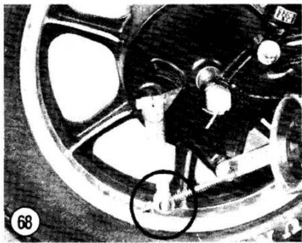
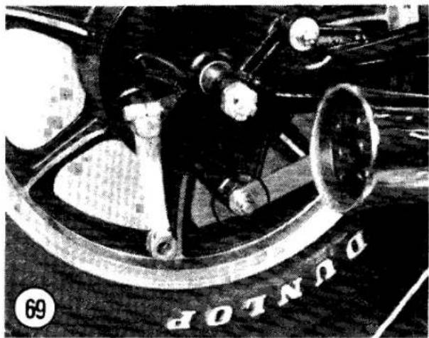


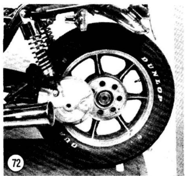
b. Adjust the drive chain play and the rear brake as described in the Chapter Three section of this supplement and in Chapter Three of the main book.
Removal/Installation (KZ550-F1 and M1)
- Support the motorcycle with the rear wheel off the ground.
- Disconnect the brake rod (Figure 68) and remove the torque link bolts at the rear brake panel (Figure 69).
- Remove the cotter pin and remove the rear axle nut.
- Pull the axle out of the wheel (Figure 70).
- Remove the axle spacer (Figure 71) from the right-hand side of the wheel.
- Remove the wheel by sliding it to the right and disengage it from the hub drive splines (Figure 72). Remove the wheel.
- To install, reverse the removal steps. Note the following:
a. Apply molybdenum disulfide grease to the final drive flange splines on the wheel and the ring gear.
b. Make sure that the wheel hub splines (Figure 73) engage with the final drive (Figure 74).
c. Tighten the axle nut to specifications (Table 26).
d. Adjust the rear brake as described in Chapter Three of the main book.
FRONT MASTER CYLINDER
Removal
(KZ550-H1, F1 AND M1)
On these models, the front brake light switch is held by a screw instead of by a locking tab (Figure 53). Apply Loctite Lock N' Seal to the threads of the screw during installation.
Installation
When installing the master cylinder, the inner clamp must be installed so that the projection (Figure 75) is facing toward the throttle housing assembly.
BRAKE SYSTEM BLEEDING (ZX550-A1 AND A2)
On models equipped with anti-dive front suspension, it is necessary to bleed the anti-dive mechanism and junction block as well as the caliper. See Figure 76 and Figure 77 for the location of the bleeder valves.
Use the techniques for bleeding the brakes as outlined in Chapter Nine of the main book. Bleed the anti-dive mechanism and brake calipers in the following manner:
a. Left caliper bleed valve.
b. Left anti-dive bleed valve.
c. Left junction block valve.
d. Right caliper bleed valve.
e. Right anti-dive bleed valve.
f. Right junction block valve.
DISC BRAKE PAD REPLACEMENT (ZX550-A1 AND A2)
Rear Brake Pad Removal
Refer to Figure 78 when performing this procedure.
- Remove the bolts securing the rear caliper to the mounting bracket.
- Carefully pull the caliper away from the brake disc and slide out the inside brake pad.
- Disengage the outside pad from the ends of the caliper holder and remove the pad.
- Use a clean rag and carefully wipe the pad sliding surfaces on the caliper holder and anti-rattle spring.


78
REAR BRAKE CALIPER (ZX550-A1 AND A2)

- Dust cap
- Bleeder valve
- Housing
- Fluid seal
- Piston
- Dust seal
- Insulator
-
Anti-rattle spring
-
Brake pad
- Brake pad
- Caliper holder
- Rubber boot
- Friction boot
- Caliper bracket
-
Mounting bolts
-
Remove the cover from the rear master cylinder reservoir. Wrap a rag around the reservoir to catch any brake fluid spills.
- Carefully push the caliper piston back into the caliper body as far as it will go.
NOTE
If the reservoir is full, brake fluid may overflow slightly when the caliper piston is pushed completely back into the caliper.
CAUTION
Do not allow any brake fluid to spill on painted surfaces or the paint will be damaged.
-
Install new inner and outer brake pads. Ensure each pad fits properly in the caliper holder.
-
Install the caliper mounting bolts and torque the bolts to 22 ft.-lb. (3.0 mkg).
- Top up the master cylinder reservoir with approved brake fluid, if necessary, and install the reservoir cap.
- Spin the rear wheel and apply the brake a few times to ensure the brakes operate properly and the pads adjust correctly.
REAR MASTER CYLINDER (ZX550-A1 AND A2)

The rear master cylinder on ZX550-A1 and A2 models has changed slightly from other models. Removal and installation of the rear master cylinder on this model is essentially the same as outlined under Rear Master Cylinder in Chapter Nine of the main book. Refer to Figure 79 when performing service procedures.
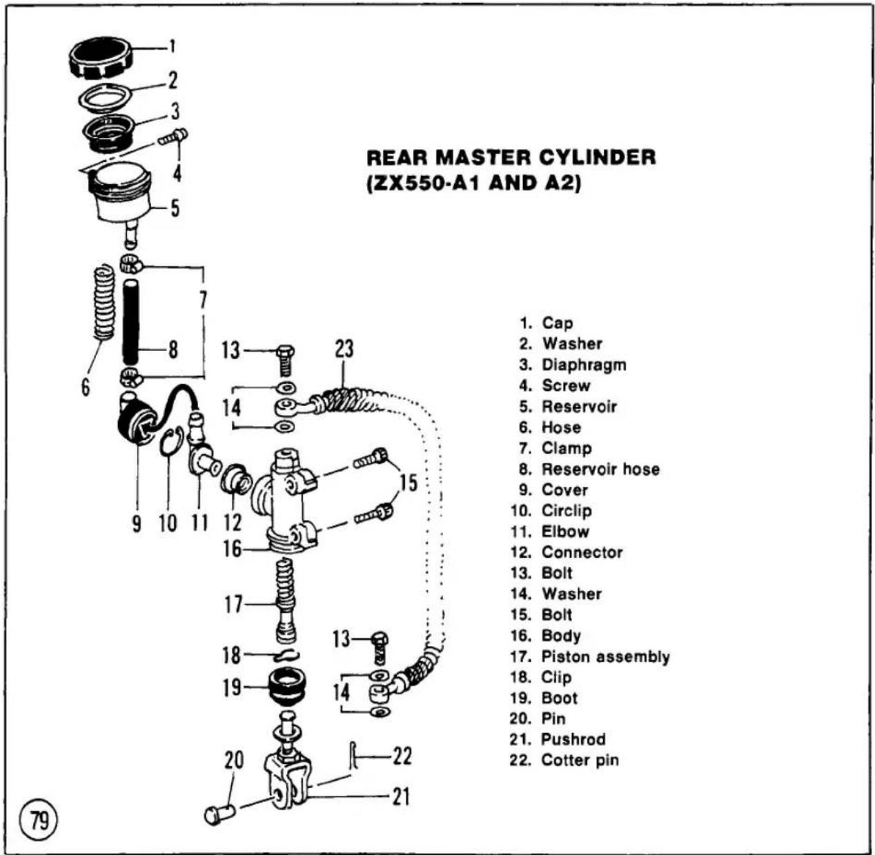
Table 21 DISC BRAKE WEAR LIMITS
| Item | in. | mm |
| Pad lining thickness | ||
| ZX550-A1, A2 | 0.039 | 1 |
| Disc thickness | ||
| Front | ||
| KZ55—H1 | 1.157 | 4.0 |
| KZ550-F1 | 0.177 | 4.5 |
| ZX550-A1, A2 | 0.177 | 4.5 |
| Rear | ||
| KZ550-H1 | 0.217 | 5.5 |
| ZX550-A1, A2 | 0.217 | 5.5 |
| Caliper assembly | ||
| KZ550-F1, M1 | Not specified | |
| Front master cylinder | ||
| KZ550-F1, M1 | Not specified | |
Table 22 DISC BRAKE TORQUES (EXCEPT KZ550-F1, M1)
| Item | ft.-lb. | mkg |
| Caliper mounting bolts | ||
| All models except ZX550 | 22 | 3.0 |
| ZX550-A1, A2 | ||
| Front | 18 | 2.5 |
| Rear | 22 | 3.0 |
Table 23 DISC BRAKE TORQUES (KZ550-F1, M1)
| Item | ft.-lb. | mkg |
| Caliper mounting bolts | 34 | 3.3 |
| Caliper holder shaft bolts | 13 | 1.8 |
Table 24 CHASSIS TORQUES (EXCEPT KZ550-H1, F1, M1 and ZX550-A1 AND A2)
| Item | ft.-lb. | mkg |
| Rear sprocket nuts | 25 | 3.5 |
Table 25 CHASSIS TORQUES (KZ550-H1)
| Item | ft.-lb. | mkg |
| Handlebar clamp bolts | 25 | 3.5 |
| Handlebar holder bolts | 72 | 10 |
| Steering stem head bolt | 31 | 4.3 |
| Rear shock absorber bolts | 51 | 7.0 |
| Rocker arm pivot shaft | 65 | 9.0 |
| Swing arm pivot shaft | 58 | 8.0 |
| Tie rod bolts | 27 | 3.8 |
Table 26 CHASSIS TORQUES (KZ550-F1, M1)
| Item | ft.-lb. | mkg |
| Front axle nut | 47 | 6.5 |
| Front fork clamp bolts | ||
| Upper | 15 | 2.1 |
| Lower | 20 | 2.8 |
| Fork bottom Allen bolt | 16 | 2.3 |
| Fork top plug | 16 | 2.3 |
| Rear axle nut | 54 | 7.5 |
| Rear shock absorber (F1) | ||
| Swivel nut | 14 | 20 |
| Mounting nuts | 18 | 2.5 |
| Air fitting | 104 in.-lb. | 1.2 |
| Steering stem head bolt | 31 | 4.3 |
| Steering stem locknuts | See text for correct procedure | |
| Swing arm pivot shafts | 9.5 | 1.3 |
Table 27 CHASSIS TORQUES (ZX550-A1 AND A2)
| Item | ft.-lb. | mkg |
| Handlebar clamp bolts | 18 | 2.5 |
| Handlebar holder bolts | 54 | 7.5 |
| Front axle nut | 58 | 8.0 |
| Rear axle nut | 69 | 9.5 |
| Rear sprocket nuts | 29 | 4.0 |
| Rear shock absorber bolts | 36 | 5.0 |
| Uni-trak | ||
| Rocker arm pivot nut | 36 | 5.0 |
| Tie-rod bolts | 36 | 5.0 |
| Swing arm pivot nut | 65 | 9.0 |
| Anti-dive | ||
| Brake plunger mounting bolts | 35 in.-lb. | 0.40 |
| Valve assembly mounting bolts | 65 in.-lb. | 0.75 |
CHAPTER TEN
CHASSIS
See Tables 24-27 for new chassis torque specifications.
FRONT FORKS
Removal/Installation
(KZ550-H1, F1 and M1; ZX550-A1 and A2)
Both fork tube air chambers are connected by a single air hose; thus both fork tubes are under equal air pressure at all times. A single air fitting is mounted on the left-hand (KZ550-H1 and ZX550-A1 and A2) or right-hand (KZ550-F1, M1) fork tube air bracket. See Figure 80. This procedure is the same as for 1981 models with the following changes.
-
KZ550-H1: In Step 3, also remove the handlebar holders as described in this section of the supplement and remove the front brake calipers as described in Chapter Nine of the main book.
-
In Step 6, during installation:
a. Oil the O-rings inside the connecting brackets. See Figure 81 or Figure 82.
b. On KZ550-H1 models, the top of the fork tube should be slightly below the top surface of the steering stem head. On KZ550-F1 and M1 models, the top of the fork tube should be even with the top surface of the steering stem head (Figure 83).
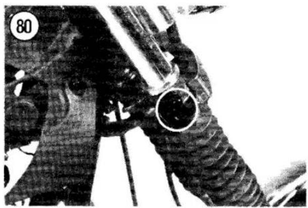
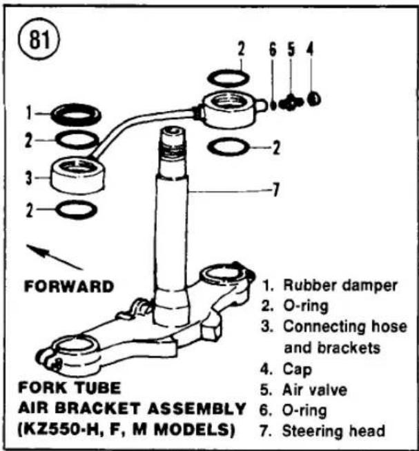
82

- Screw
- Bleeder valve
- Plunger
- Anti-dive brake plunger assembly
- Bolts
- Washer
- Anti-dive valve assembly
- O-rings
- Clip
- Fork cap
- O-ring
- Seal
- Seal
- O-ring
- Connecting pipe assembly
- Air valve assembly
- O-ring
- Clip
- Spring
- Inner fork tube
- Guide bushing
- Damper rod
- Clip
- Spring
- Washer
- Spacer
- Spacer
- Seal
- Boot
- Clip
- Seal
- Washer
- Guide bushing
- Washer
- Bolt
- Bleeder valve
- Junction block
- Hose
- Junction block
- Bracket
- Lower fork tube

- When removing the fork assembly on ZX550-A1 models, disconnect the hydraulic lines at the anti-dive units. During reassembly, refer to Brake System Bleeding in this supplement and bleed the brakes and anti-dive unit as described.
FRONT FORK ANTI-DIVE UNIT (ZX550-A1 AND A2)
The anti-dive assembly consists of 2 basic components; the brake plunger (A, Figure 84) and the anti-dive valve (B, Figure 84). Neither component is repairable. If a component is defective and the anti-dive function does not operate correctly, the faulty component must be replaced.
Adjustment
Anti-dive unit adjustment procedures that can be performed by the home mechanic are described in the Chapter Three section of this supplement.
Inspection
Visually inspect the anti-dive unit for fork oil or brake fluid leakage.
-
If the anti-dive unit is leaking fork oil, replace the O-seals installed between the anti-dive unit and the lower fork tube as described in this chapter.
-
If the anti-dive unit is leaking brake fluid, check the tightness of the air bleed screws. Also check the condition of all brake line attachments at the anti-dive housing. If these checks prove okay, the brake plunger is probably damaged or working incorrectly. Replace the brake plunger as described in this supplement.
Brake Plunger
- Remove the bolts securing the brake plunger assembly to the anti-dive valve (A, Figure 84). Carefully remove the plunger assembly. Take care not to damage the O-ring between the plunger and the anti-dive valve.
- Loosen one of the fittings on the metal brake line and shift the plunger assembly around until the plunger rod inside the


assembly is accessible. Retighten the brake line fitting enough to keep the fluid from running out.
CAUTION Do not attempt to move the plunger assembly without first loosening one of the fittings on the metal brake line or the brake line will be bent and distorted.
CAUTION Take care not to spill brake fluid on the painted surfaces of the front forks or the paint may be damaged.
- Hold your finger over the plunger rod and apply the front brake slightly. Check that the plunger rod extends approximately 2 mm (0.08 in.) as the front brake is applied. Release

the brake lever and push the plunger rod back into the plunger body. The plunger rod must move smoothly in both directions. If the rod is stuck or does not move smoothly, replace the brake plunger assembly.
- Install the brake plunger assembly. Keep the following points in mind:
a. Make sure the O-ring is in good condition. Replace it if necessary.
b. Retighten the metal brake line fitting and bleed the brakes as outlined in this supplement.
Anti-dive Valve
Test/Removal/Installation
- Remove the brake plunger assembly from the anti-dive valve as described in this section of the supplement.
- Remove the fork tube from the motorcycle. Remove the top bolt and remove the main fork spring.
- Tape over the air pressure equalizer hole in the fork leg to keep the fork oil from running out.
- Hold the fork leg vertically and compress the fork tube. Alternately press and release the plunger rod in the anti-dive assembly as the fork tube is compressed. The fork compression should be noticeably stiffer when the plunger rod is pressed than when released. The extension (rebound) stroke of the fork tube should be the same whether or
not the plunger is pressed. Replace the anti-dive valve if it does not function smoothly and correctly.
- Installation is the reverse of removal. Keep the following points in mind:
a. If the anti-dive valve was removed, ensure the O-rings between the valve assembly and the fork tube are in good condition.
b. Install the fork spring and fork top bolt and install the fork on the motorcycle.
c. Install the brake plunger assembly as described in this section of the supplement. Be sure to bleed the brakes.
HANDLEBARS AND HOLDERS (KZ550-H1)
Removal/Installation
Refer to Figure 85 for these procedures.
-
To remove the left-hand handlebar:
a. Loosen the bolt securing the clutch lever.
b. Remove the screws holding the left-hand switch housing together and separate the housing.
c. Remove the handlebar clamp bolt and end plug. Pull the handlebar out of the holder. -
To remove the right-hand handlebar:
a. Loosen the front master cylinder clamp bolts.
b. Remove the screws holding the left-hand switch housing together and separate the housing.
c. Remove the throttle grip.
d. Remove the handlebar clamp bolt and plug. Pull the handlebar out of the holder.
- To remove either handlebar holder:
a. Remove the screws securing the steering stem head cover and remove the cover.
b. Remove the rubber cap covering the handlebar holder bolt.
c. Remove the handlebar holder bolt, the positioning plate Allen bolt and the positioning plate. Remove the handlebar holder.
- Install the handlebar holder onto the steering stem head as follows:
a. Loosen the front fork clamp bolts (3 on each fork). Slide the fork leg down until the top of the fork is slightly below the upper surface of the steering stem head.
b. Finger-tighten the upper fork clamp bolt to hold the fork in this position. Leave the other clamp bolts loose at this time.
c. Install the handlebar holder and positioning plate. Finger-tighten the holder bolt and the plate Allen bolt.
d. Tighten the fasteners in the following order to the specifications in Table 25: handlebar holder bolt, fork clamp bolts, positioning plate Allen bolt.
WARNING
The fasteners must be tightened in the specified order to the specified torque for proper handlebar installation.
- The remainder of installation is the reverse of the removal steps. Note the following:
a. The lower half of each switch housing has a peg which must fit into the hole in the handlebar. See Figure 86.
b. The master cylinder clamp must be installed with the small projection toward the throttle housing (Figure 75). Tighten the upper clamp bolt first, then the lower bolt. There will be a gap at the lower end of the clamp after tightening.
c. Adjust the throttle and clutch cables and the front brake as described in Chapter Three of the main book.
STEERING HEAD (KZ550-H1, F1 AND M1)
Adjustment
- KZ550-H1: Remove the fairing.
- Raise the front wheel off the ground; support the motorcycle securely under the engine.
- Remove the fuel tank to protect its finish. See Chapter Seven of the main book.
- KZ550-H1: Remove the screw securing the steering head cover and remove the cover.
- On KZ550-F1 and M1 models, remove the cover (Figure 87).


-
Loosen both lower fork clamp bolts (Figure 88). Loosen the steering stem head bolt (Figure 89).
-
Completely loosen the upper stem locknut (Figure 90).
-
If the steering was too tight, loosen the lower stem locknut. If the steering was too loose, tighten the lower stem locknut. Turn the locknut 1/8 turn at a time.
-
When adjustment is correct, hold the lower stem locknut to keep it from turning while you tighten the upper stem locknut securely.
-
Torque the steering head bolt and the lower fork clamp to specification. Recheck the steering adjustment and repeat this procedure, if necessary.
-
Install all parts previously removed.
Steering Stem
Bearing Lubrication
Several special tools are required for bearing replacement. If the inspection procedures indicate the need for bearing replacement, take the job to a dealer or qualified mechanic.
-
Raise the front wheel off the ground; support the motorcycle securely under the engine.
-
Remove the fuel tank to protect its finish; see Chapter Seven of the main book.
-
Remove the fairing (KZ550-H1), the front wheel and both fork legs.
-
Remove the headlight and its housing (A, Figure 91).
-
Remove the front turn signals (B, Figure 91) and the fork covers (C, Figure 91).
-
Remove the handlebars and their holders.
-
Remove the 2 mounting bolts securing the brake hose joint to the steering stem base. Remove the front brake system as an assembly, without disconnecting any hydraulic lines.
-
Remove the steering stem head bolt and flat washer.
-
Remove the steering stem head and meter assembly.
CAUTION
Store the meters right side up. If they are upside down or sideways, the instrument fluids will leak and the meters won't work properly.
-
Push up on the stem base while removing the steering stem locknuts (use the special wrench in the bike's tool kit). Remove the steering stem and stem base as an assembly.
-
Clean the bearing races and tapered roller bearings with solvent.
-
Check the roller bearings and races visually for wear or damage. If any need replacement, take the job to a dealer or qualified mechanic.
-
Grease the bearings and races.
-
Reverse Steps 1-10 to install the steering stem. Adjust the steering as described in this section of the supplement.
REAR SHOCK ABSORBERS (KZ550-F1)
This model is equipped with 4-way, damping adjustable air shocks. Both shock absorber air chambers are connected by a single air hose; thus both shocks are under equal pressure at all times. A single air fitting is mounted on the left-hand shock absorber. See Figure 92.
Removal/Installation
- Place the bike on the centerstand so that the rear wheel clears the ground.
- Remove the air valve cap and depress the valve stem to release all air pressure from both shock absorbers.

REAR SHOCK ABSORBERS (KZ550-F1)
- Hose
- Swivel nut
- Fitting
- Male pipe
- Cap
- Air valve
- Damper
- Dust boot
- Shock unit
- Damper
- Hose clamp
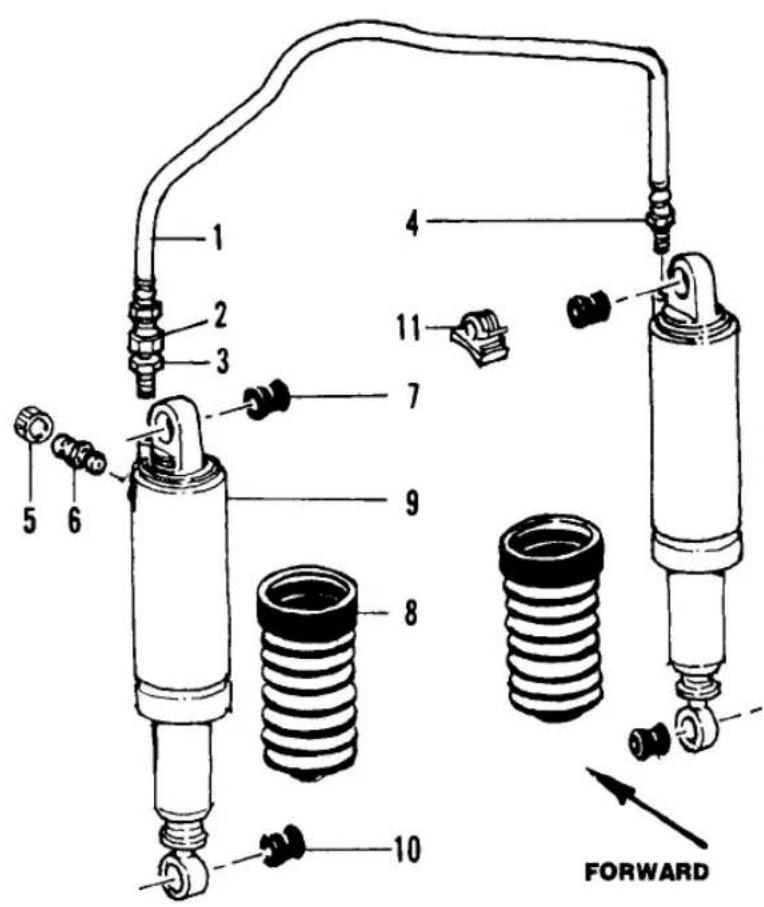
- Disconnect the air hose from both shock absorbers.
- Remove the upper and lower acorn nut and washers from the shock absorber.
- Remove the shock absorber.
CAUTION
After removing the shock absorber(s), do not turn them upside down or sideways. Failure to observe these cautions will result in loss of oil through the air hose connections.
- Install by reversing these steps. Note the following:
a. If any oil was lost from the shock, take it to a dealer to check and adjust the level.
b. Refill the shock air pressure as described in the Chapter Three section of this supplement.
c. Tighten the shock mounting bolts to specifications in Table 26.
SWING ARM (KZ550-F1 AND M1)
Removal/Installation
Refer to Figure 93.
- Remove the rear wheel and shock absorbers as described in this supplement.
- Disconnect the torque link rod from the right-hand side of the swing arm.
- Remove the caps from both sides (Figure 94) of the swing arm.
NOTE Support the middle section of the swing arm with wood blocks before starting Step 4.
- Remove the pivot shaft locknuts and remove the shafts. See Figure 95.

- Slide the dust cover away from the propeller shaft.
- Push the locking pin (Figure 93) about 3 mm into the drive gear joint, slide the propeller shaft off the joint and remove the swing arm assembly.
- Clean the old grease from the ends of the propeller shaft and joint and apply a liberal amount of high-temperature grease.
- To install, reverse the removal steps. Note the following:
a. Pack the caged bearing rollers and the races with molybdenum disulfide chassis grease.
b. After positioning the propeller shaft on the universal joint, align and release the locking pin. Pull back on the swing arm assembly to make sure the locking pin is installed correctly.
c. Measure the left swing arm side clearance as shown in Figure 96. It should be 0.055-0.0630 in. (1.4-1.6 mm). Adjust the clearance by turning the pivot shafts. Tighten the pivot shaft locknuts to specifications (Table 26). Recheck the left swing arm side clearance.
Inspection
- Remove the grease seals from both sides of the swing arm and remove the roller bearings.
- Wash the bearings and the swing arm races with solvent to remove all traces of old bearing grease. Dry the bearings with a lint-free cloth.
- Inspect the bearings and races for discoloration or other damage. Replace them if necessary.
NOTE
Removal and installation of the bearing races require special tools. Refer all service work to a dealer or a qualified mechanic. Improper removal attempts may damage the swing arm.
UNI-TRAK REAR SUSPENSION (KZ550-H1)
This model uses Kawasaki's single-shock Uni-Trak rear suspension. Figure 97 shows


the suspension parts and how they move during rear wheel travel. Figure 98 is an exploded view of the rear suspension. Table 28 lists Uni-Trak specifications.
Removal/Installation
- Remove the rear wheel as described in this supplement.
- Remove the engine sprocket as described in Chapter Six of the main book.
- Remove the seat and side covers.
- Remove the left-hand air cleaner housing as described in this supplement.
- Remove the battery and its housing.
- Remove the rocker arm pivot shaft nut and the pivot shaft.
- Remove the swing arm pivot shafts (the shaft nuts cannot be removed unless the engine is removed).
- Remove the swing arm, rocker arm, tie rod, shock absorber and drive chain as an assembly.
- Installation is the reverse of removal. Note the following:
a. Make sure the swing arm pivot shaft nuts are in the correct position (A, Figure 99).
b. Tighten all fasteners as specified in Table 25.
c. Check and adjust the drive chain play and the rear brake.
Inspection and Lubrication
- Disassemble the suspension and wash the sleeves, needle bearings and spherical bearings in solvent.
- Measure the OD of the swing arm sleeves and the rocker arm sleeve. Compare with Table 28 and replace any parts that are out of specification.
- Move the spherical bearings in the tie rod to check for wear. If the bearings are loose or if the outer portion of the bearing is thinner than specified in Table 23, replace the tie rod and bearing as a set.
- Needle bearing wear is difficult to measure. Visually check the bearings for damage, excessive wear or the bluish tint that indicates heat damage. If necessary, replace the bearing and sleeve as a set.
- Check the shock absorber for oil leakage; replace it if leakage has occurred. Extend and compress the shock through its full range; it should move smoothly and offer equal resistance during both compression and extension. Replace the shock if its condition is doubtful.
WARNING
The shock absorber contains pressurized nitrogen. It must be disposed of properly. Do not incinerate or attempt to disassemble the shock. Take it to a dealer for safe disposal.

98

- Shock absorber
- Rubber bushing
- Collar
- Pivot shaft
- Sleeve
- Grease sea!
- Needle bearing
- Rocker arm
- Nut
- Grease seal
- Collar
- Spherical bearing
-
Tie rod
-
Pivot shaft
- Sleeve
- Grease seal
- Needle bearing
- Chain guard
- Nut
- Bracket
- Mud guard
- Mud guard
- Torque link
- Swing arm
- Bracket

- Check the bushings at the top and bottom of the shock absorber. Replace if worn, cracked, hardened or otherwise damaged.
- Lubricate the outer surface of the sleeves, the needle bearings and the spherical bearings with molybdenum disulfide grease.
- Assemble the suspension parts; tighten all fasteners to specifications in Table 25.
UNI-TRAK REAR SUSPENSION
(ZX550-A1 AND A2)
Shock Absorber
Removal/Installation
Refer to Figure 100 for this procedure.
100
REAR SHOCK ABSORBER (ZX550-A1 AND A2)
- Bolt
- Bushing
- Shock absorber
- Nut
- Bolt
- Spacer
- Control link
- Bearing
- Washer
- Bolt
- Bolt
- Bearing
- Control link
- Washer
- Bolt
- Bolt
- Washer
- Bearing
- Rocker arm
- Spacer
- Dust seal
- Bearing
- Spacer
- Washer
- Bushing
- Bushing
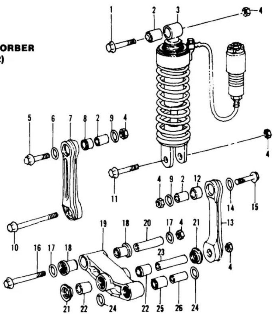

- Remove the rear wheel.
- Remove the seat and side covers.
- Remove the bolts securing the chain guard to the swing arm and remove the chain guard.
- Loosen and remove the rear shock reservoir.
- Remove the upper and lower bolts securing the shock absorber.
- Support the swing arm and lift the shock absorber out of the frame.
- Check the shock absorber body and reservoir for damage.
- Installation is the reverse of these steps. Tighten the shock absorber mounting bolts as specified in Table 27.
Swing Arm
Removal/Installation
Refer to Figure 101 for this procedure.
- Remove the shock absorber as described in this supplement.
- Remove the bolts securing the lower control links to the swing arm.
- Remove the nut securing the swing arm pivot bolt and carefully tap the pivot bolt out of the frame. Carefully slide the swing arm out of the frame.
- Installation is the reverse of these steps. Install the shock absorber and tighten all the rear suspension mounting bolts as specified in Table 27.
Table 28 UNI-TRAK SUSPENSION SPECIFICATIONS (KZ550-H1)
| Item | in. | mm |
| Swing arm sleeve OD | 0.983 | 24.96 |
| Rocker arm sleeve OD | 0.865 | 21.96 |
| Spherical bearing thickness | 0.012 | 0.3 |
INDEX
A
Advance mechanism, ignition 175-176
Air filter 52-53, 252-253
Air suction system 161-163
Air suction valves (U.S. models) 54-55
Alternator 180-182
Anti-dive fork 248
Axle 201
B
Battery 34,170-173
Block, cylinder 88-91
Brakes 207-224
Bleeding 207-208, 290
Brake line 209
Calipers 213-217
Disc brake 47-50, 207, 220-221,
251, 290-291
Drum brake 50-51, 221-224
Fluid change 208
Front master cylinder 217-218, 290
Light failure switch 189
Light switch 48,251
Master cylinder rebuilding 217
Pads 49, 209-213, 290
Rear master cylinder 218-220, 291-292
Troubleshooting 30
Breaker point ignition 57-60, 173-174
C
Cam chain and tensioner 72-74
Camshaft 76-81,257
Carburetor 62-65, 148-159, 267-273
Chain, drive 39-42
Charging system 179-181
Chassis 23-30
Drive chain 244
Fairing 228
Front forks 228-235, 294-297
Rear shock absorbers 241-242
Steering head 236-241
Swing arm 243-244
Clutch 127-132, 266
Clutch release 38-39
Clutch release mechanism ..... 124-127, 265
Lever 38
Operation 124
Troubleshooting 22
1982 and later service information 247
Coil
Ignition 176-178
Pickup 178
Condenser 59-60
Connecting rod 94-95, 111-115, 258-262
Contact breaker points 57-60
Control cables 37
Crankcase 107-109, 258
Crankcase breather 161
Crankshaft 111-115, 258-262
Cylinder block 88-91
Cylinder compression 65
Cylinder head 81-84
D
Disc brake .... 47-50, 207, 209-217, 220-221, 251, 290-291
Drive chain 39-42, 244
Drum brake 50-51, 221-224
E
Electrical system Alternator rotor 181-182
Alternator stator 181
Battery 170-173
Charging system 179-181
Contact breaker points and condenser service 175
Fuel and oil level warning system ..... 277-278
Fuel level sensor 190
Fuel gauge 190-191
Fuses 169-170
Horn 191
IC ignition (transistorized ignition) 179, 275-276
Ignition advance mechanism 175-176
Ignition coil 176-178
Ignition system 173-175
Lighting system 186-189
Pick coil (transistorized ignition) 178
Spark plugs 175
Starter clutch 184-185
Starter motor 182-184
Starter solenoid 185-186
Starting system 182, 277
Troubleshooting 30-32
Turn signal cancelling system 189-190
Wiring diagrams .... end of book
Engine
Break-in 71
Cam chain and tensioner 72-73
Cam chain inspection 115
Cam chain tensioner 73-74
Camshaft 76-81
Crankcase 107-109
Crankcase assembly 117-120
Crankshaft and connecting rods ..... 111-115
Cylinder block 88-91
Cylinder head 81-84
Engine design 71
Engine removal/installation 97-102
Oil and filter 35
Oil cooler (KZ550-D) 97
Oil filter bypass valve 102
Oil pump 102-107
Pistons and rings 91-96
Primary chain inspection 115-116
Secondary shaft and starter clutch 109-111
Servicing engine in frame 71-72
Tools 70-71
Troubleshooting 9
Tune-up 51,251
Valve cover 74-76
Valves and guides 84-88
1982 and later service information ..... 258-262
Engine sprocket 135
Evaporative emission control system 274
Exhaust system 167-168, 274
F
Fast idle 160
Final drive gear lubrication 251
Fork, anti-dive 248, 296-297
Front brake light switch 189
Front forks 43-45, 228-235, 247-248
Fuel gauge 190-191
Fuel level sensor 190, 279-281
Fuel system 53,253
Air suction system (U.S. models) ..... 161-163
Carburetor operation 148-139
Carburetor service 151-159
Carburetor troubleshooting 149-150
Carburetor tuning 150-151
Crankcase breather 161
Fast idle adjustment 160
Fuel level inspection 159-160
Fuel level sending unit 165
Fuel tank 163-165, 273-274
Fuel tap 165
Idle mixture adjustment (non U.S. models) 160
Rejetting 150
1982 and later service information 253-255, 267-274
Fuses 169-170
G
Gauges, solid-state 282-285
Gears, transmission 143-146
General information 1-8,247
H
Handlebars 297
Hazard flashing system 281-298
Headlight 186-189
Horn 191
Hydraulic disc brakes 207
1
Idle mixture 64,160
Idle speed 63-64
Ignition advance mechanism 175-176
Ignition coil 176-178
Ignition system 173-175
Ignition timing (contact point ignition) 60-61
Ignition timing (transistorized) 60-61
J
Jet needle 150-151
L
Lighting system 186-189, 278
Lubrication, maintenance and tune-up Air filter 52
Air suction valves (U.S. models) 54-55
Battery 34
Carburetor 62-65
Clutch adjustment 38-39
Contact breaker points 57-60
Cylinder compression 65
Disc brake 47-50
Drive chain 39-42
Drum brake 50-51
Emission controlled motorcycles 33
Engine oil and filter 35
Engine tune-up 51
Front forks 43-45
Fuel system 53
General lubrication 37-38
Ignition timing (contact point ignition) 60-61
Ignition timing (transistorized ignition) 62
Model identification 33-34
Nuts, bolts and fasteners 51
Spark plugs 53-54
Steering 43
Storage 65-66
Swing arm 42
Rear shock absorbers 46
Tires 46-47
Valve clearance 55-57
Wheel bearing lubrication 47
M
Main bearing 112-114
Main jet 151
Master cylinder 217-220
Misfiring 16-20
Model identification 33-34, 247
N
Needle jet 151
Neutral finder 141
Neutral switch 135
0
Oil change, forks 44-45, 248
Oil change, final drive 251
Oil cooler 97
Oil filter 35-36
Oil filter bypass valve 102
Oil level check, final drive 251
Oil pump 102-107
P
Performance, poor 15-22
Pilot jet 150
Pistons and rings 91-96, 258
Plugs, spark 53-54
Points 57-60
R
Rear shock absorbers 46, 248-250, 300-301
Rejetting, carburetor 150
Regulator/rectifier 180-181
Reserve lighting unit 189
Rings and pistons 91-96
Rod, connecting 94-95
Rotor, alternator 181-182
S
Secondary shaft 109-111
Sending unit, fuel level 165
Shift detent 139
Shift drum 14i
Shift forks 141-143
Shift linkage 135-139
Shock absorbers, rear 46, 241-242, 248-250, 300-301
Spark plugs 53-54, 175
Speedometer gear lubrication 196
Speedometer/tachometer cables 38, 247
Spring preload 249
Sprocket cover 133-135
Sprocket, rear 220
Starter clutch 109-111, 184-185
Starter lockout switch 186
Starter motor 182-184
Starter solenoid 185-186
Starting difficulties 9-15
Starting system 182, 277-278
Stator, alternator 181
Stator coil 180
Steering 43
Steering head 236-241, 298-299
Storage 65-66
Suction valve 162
Swing arm 42, 243-244, 301-302
Switches
Brake light failure switch 189
Brake light switch 48,251
Front brake light switch 189
Neutral switch 135
Starter lockout switch 186
1982 and later service information ..... 285-287
T
Tachometer/voltmeter 281-282
Throttle cable 62-63

Throttle grip 37-38
Throttle slide 150
Timing 60-62
Tires 46-47, 201-207
Transistorized ignition 174-175
Transmission 139-141
Engine sprocket 135
Gears 143-146
Neutral switch 135
Shift detent 139
Shift drum and forks 141-143
Shift linkage 135-139
Sprocket cover 133-135
Troubleshooting 22-23
Troubleshooting
Brakes 30
Charging system 32
Chassis 23-30
Clutch 22
Drive train 23
Electrical system 30-32
Engine 9
Fuses 32
Lighting 32
Performance, poor 15-22
Starting difficulties 9-15
Transmission 22-23
Wiring 32
Tubeless tires 205-207
Tube-type tires 201-205
Tune-up, engine 51, 251
Turn signal cancelling system 189-190, 287
Turn signal flasher 189
U
Uni-trak rear suspension 302-306
V
Vacuum switch 163
Valve clearance 55-57
Valve cover 74-76
Valves and guides 84-88
W
Wheels
Front wheel 193-196
Rear wheel 197-200, 288-289
Speedometer gear lubrication 196
Wheel bearings and seals 200-201
Wheel bearing lubrication 47
1979-1980 KZ500B1, B2 (Europe)

1980 KZ550A1 (U.S. & Canada)
![graph TD A["Turn Signal AND Running Light"] --> B["Tachometer Lights"] B --> C["BraKE LIGHT Failure Indicator"] C --> D["Oil Pressure Warning Light"] D --> E["Turn Signal Indicator (Right)"] E --> F["High Beam Warning"] F --> G["Neutral Indicator"] G --> H["Turn Signal Indicator (Left)"] H --> I["Sp…](/content/2026/06/1280271/images/8a2835d1ab439642f3a14d921dffa347d8324d35de6d1e0366316de1878acc91.jpg)


1981 KZ550C2 (Europe & U.K.)
![graph TD A["Turn Signal Light (RIGHT)"] --> B["Tachometer Lights"] B --> C["Fuel Warning Brake Light Failure Indicator Oil Pressure Warning Light"] C --> D["Turn Signal Indicator L (RIGHT)"] D --> E["High Beam Warning"] E --> F["Neutral Indicator"] F --> G["Turn Signal Indicator (LEFT)"] G --> H["Di…](/content/2026/06/1280271/images/ffc8ed5612affa806c62c5307854496e3920e6685911ab700c72d82723eb8fb6.jpg)




| Color Code | ||
| W - White | G/O - Green/Orange | |
| B - Black | GL - Green/Blue | |
| R - Red | CW - Green/White | |
| G - Green | LW - Blue/White | |
| Y - Yellow | YW - Grey/Orange | |
| O - Orange | OW - Green/White | |
| P - Pink | YW - Yellow/White | |
| L - Blue | PW - Pink/White | |
| Br - Brown | BOW - Brown/White | |
| Gr - Grey | BW - Black/White | |
| SB - Sky blue | BR - Black/Red | |
| DQ - Dark green | BL - Black/Blue | |
| RY - Red/Yellow | BY - Black/Yellow | |
| RG - Red/Green | BG - Black/Green | |
| RL - Red/Blue | BB - Black/Brown | |
| RP - Red/Pink | GRs - Black/Grey | |
| R/Gr - Red/Cyan | LY - Blue/Yellow | |
| L/O - Blue/Orange | GY - Green/Yellow | |
1982-1983 KZ500B4 & KZ550A3 (Except U.S. & Canada)

- Green to connector on some models.
- Twin horns on some models.
- Black on some models.
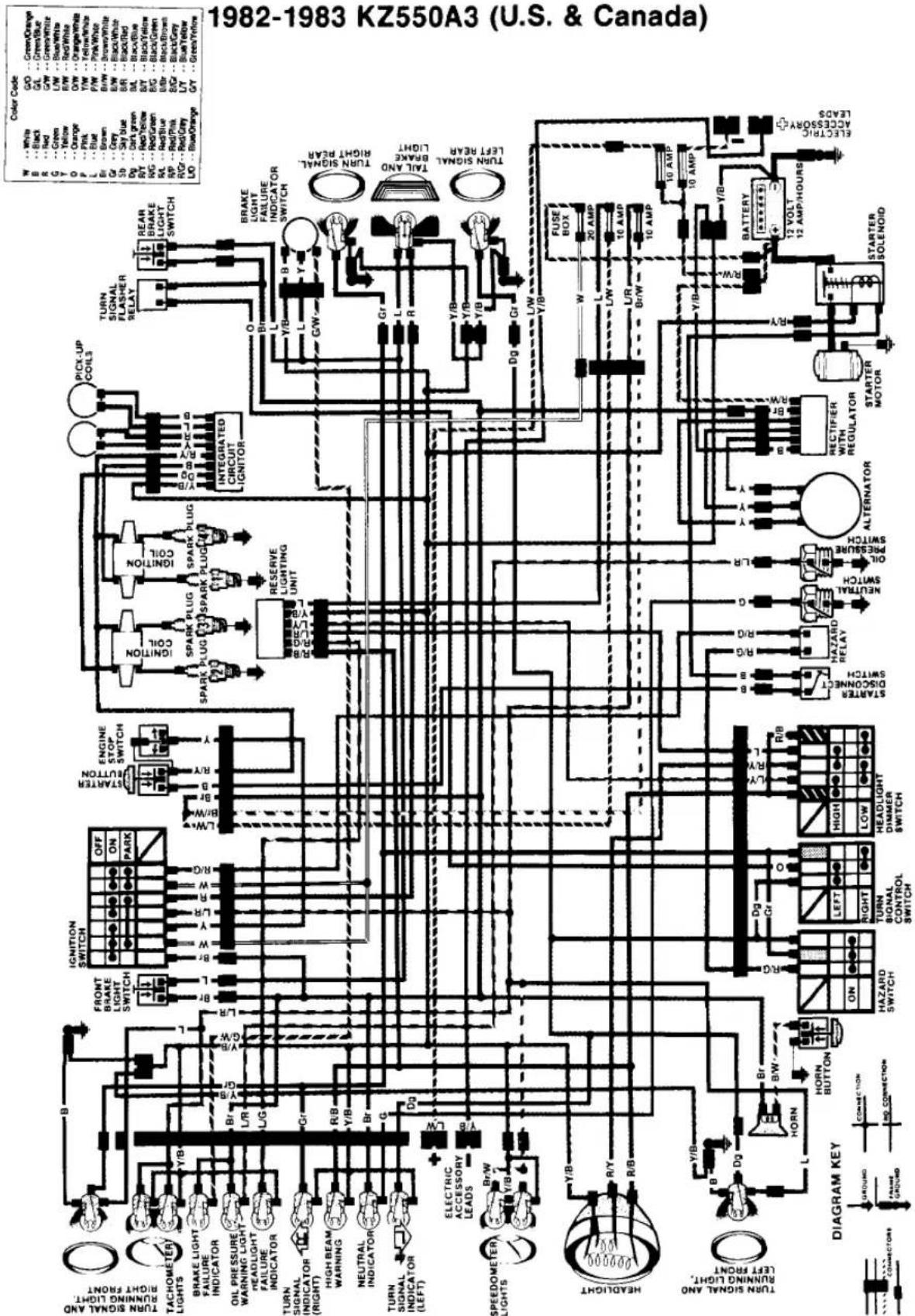

| Color Code | |||
| W | - White | GO | - Green/Orange |
| B | - Black | GA | - Green/Blue |
| R | - Red | GW | - Green/White |
| G | - Green | LW | - Blue/White |
| F | - Yellow | RW | - Red/White |
| O | - Orange | OW | - Orange/White |
| P | - Pink | YW | - Yellow/White |
| L | - Blue | PW | - Pink/White |
| Br | - Brown | Br/W | - Brown/White |
| Gr | - Grey | Gr/B | - Black/White |
| Sb | - Sky Blue | SB/B | - Black/Red |
| Bg | - Dark green | BL | - Black/Blue |
| - Red/Yellow | B/F | - Black/Blue/Gro | |
| B/G | - Red/Green | BG | - Black/Green |
| BL | - Red/Blue | B/B/B | - Black/Brown |
| BP | - Red/Blue | B/G/B | - Black/Gray |
| B/Gr | - Red/Gray | LY | - Blue/Yellow |
| LO | - Blue/Orange | GY | - Green/Yellow |
1982-1983 KZ550C3 (Except U.S. & Canada)
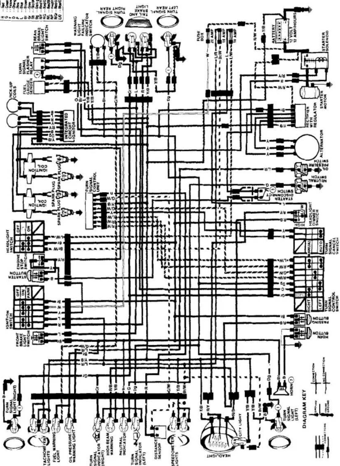
- Grey to connector on some models.
- Twin horns on some models.
- Switch not on some models.
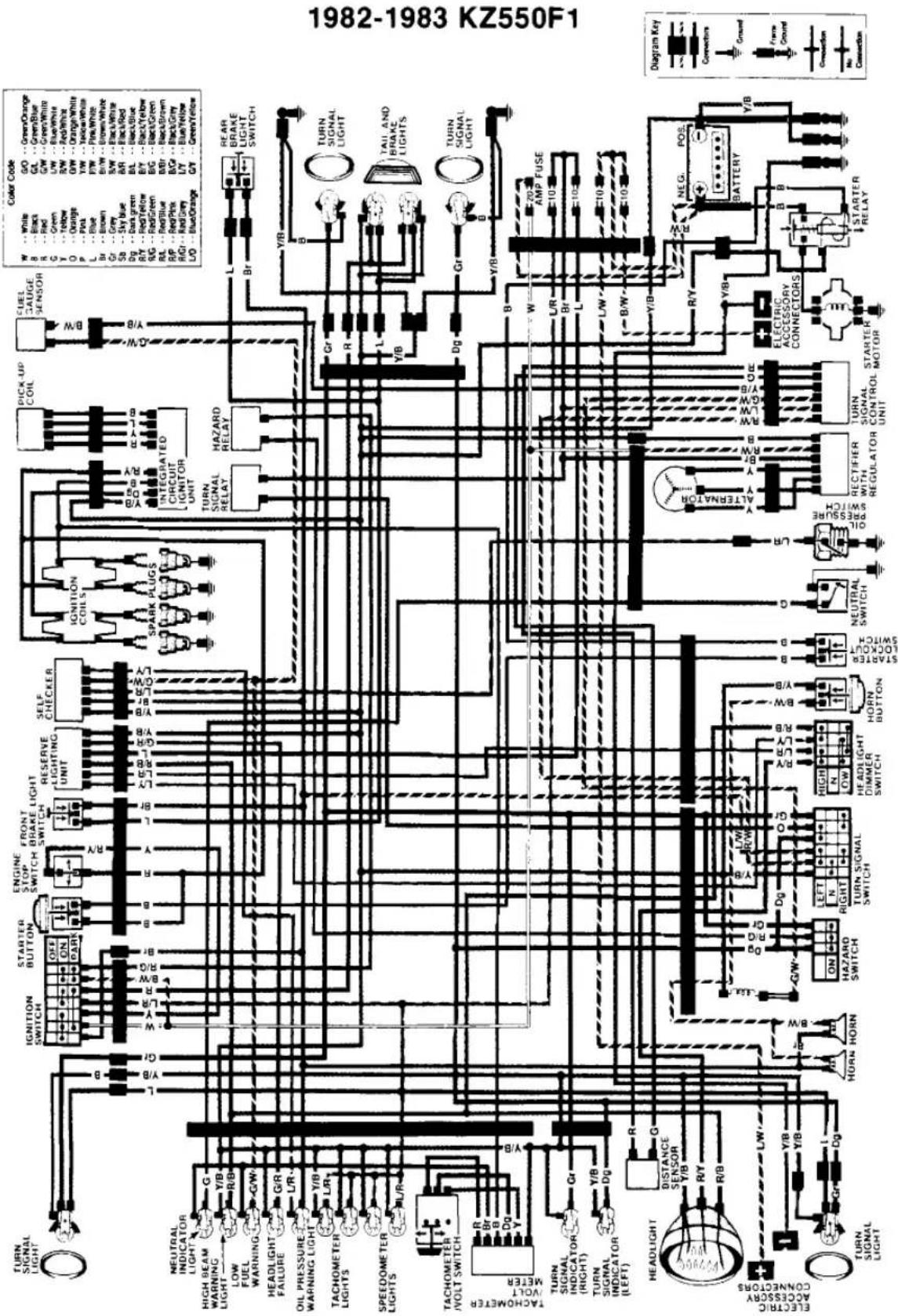
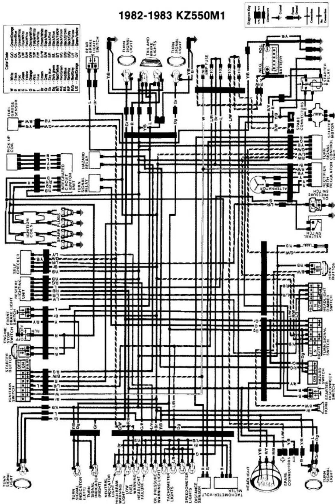




- KAWASAKI
- CONTENTS
- QUICK REFERENCE DATA ...... XI
- CHAPTER ONE
- GENERAL INFORMATION .... 1
- CHAPTER TWO
- TROUBLESHOOTING 9
- CHAPTER THREE
- LUBRICATION, MAINTENANCE AND TUNE-UP 33
- CHAPTER FOUR
- ENGINE 70
- CHAPTER FIVE
- CLUTCH 124
- CHAPTER SIX
- TRANSMISSION 133
- CHAPTER SEVEN
- FUEL AND EXHAUST SYSTEMS 148
- CHAPTER EIGHT
- CHAPTER NINE
- WHEELS, TIRES AND BRAKES 192
- CHAPTER TEN
- CHASSIS 228
- SUPPLEMENT
- 1982 AND LATER SERVICE INFORMATION 246
- INDEX 307
- WIRING DIAGRAMS ...... END OF BOOK
- QUICK REFERENCE DATA
- INTRODUCTION
- GENERAL INFORMATION
- MANUAL ORGANIZATION
- SERVICE HINTS
- WARNING
- SAFETY FIRST
- EXPENDABLE SUPPLIES
- SHOP TOOLS
- EMERGENCY TOOL KITS
- HIGHWAY
- OFF-ROAD
- ON THE MOTORCYCLE
- IN THE TRUCK
- TROUBLESHOOTING AND TUNE-UP EQUIPMENT
- VOLTMETER, OHMMETER, AND AMMETER
- HYDROMETER
- COMPRESSION TESTER
- DWELL METER (CONTACT BREAKER POINT IGNITION ONLY)
- TACHOMETER
- STROBE TIMING LIGHT
- TUNE-UP KITS
- MANOMETER (CARBURETOR SYNCHRONIZER)
- FIRE EXTINGUISHER
- TROUBLESHOOTING
- ENGINE
- STARTING DIFFICULTIES
- FUEL DELIVERY
- IGNITION
- COMPRESSION
- 3
- NORMAL
- CARBON FOULED
- OIL FOULED
- LEAD FOULED
- OIL AND LEAD FOULED
- FUEL ADDITIVE RESIDUE
- WORN
- PREIGNITION
- INCORRECT HEAT RANGE
- POOR PERFORMANCE
- POOR IDLING
- ROUGH RUNNING OR MISFIRING
- GRADUAL
- LOSS OF POWER
- SUDDEN
- ENGINE RUNS HOT
- PISTON SEIZURE AND DAMAGE
- CLUTCH AND TRANSMISSION
- DRIVE TRAIN
- CHASSIS
- BRAKES
- ELECTRICAL SYSTEM
- CHARGING SYSTEM
- LIGHTING
- FUSES
- WIRING
- LUBRICATION, MAINTENANCE AND TUNE-UP
- NOTE
- EMISSION CONTROLLED MOTORCYCLES
- MODEL IDENTIFICATION
- BATTERY
- CAUTION
- ENGINE OIL AND FILTER
- OIL LEVEL INSPECTION
- OIL AND FILTER CHANGE
- GENERAL LUBRICATION
- CONTROL CABLES
- CONTROL PIVOTS
- THROTTLE GRIP
- SPEEDOMETER/TACHOMETER CABLES
- IGNITION ADVANCE
- CLUTCH ADJUSTMENT
- CLUTCH LEVER PLAY
- CLUTCH RELEASE ADJUSTMENT
- DRIVE CHAIN
- CHAIN LUBRICATION
- CHAIN PLAY INSPECTION
- ADJUSTMENT
- CHAIN WEAR
- SWING ARM
- STEERING PLAY INSPECTION
- STEERING HEAD LUBRICATION
- AIR PRESSURE
- INSPECTION
- OIL CHANGE
- REAR SHOCK ABSORBERS
- TIRES
- PRESSURE
- TIRE WEAR
- WHEEL BEARING LUBRICATION
- DISC BRAKE
- BRAKE FUNCTION
- PEDAL HEIGHT
- PEDAL FREE PLAY
- BRAKE LIGHT SWITCH ADJUSTMENT
- FLUID LEVEL INSPECTION
- ADDING BRAKE FLUID
- PAD WEAR INSPECTION
- BRAKE SEAL REPLACEMENT
- BRAKE HOSE REPLACEMENT
- DRUM BRAKE
- PEDAL PLAY
- LINING WEAR INSPECTION
- BRAKE LUBRICATION (DRUM BRAKE)
- NUTS, BOLTS AND FASTENERS
- ENGINE TUNE-UP
- AIR FILTER
- REMOVAL/INSTALLATION
- CLEANING
- FUEL SYSTEM
- FUEL SYSTEM CLEANING
- FUEL LINE REPLACEMENT
- SPARK PLUGS
- HEAT RANGE AND REACH
- REMOVAL/INSPECTION/INSTALLATION
- AIR SUCTION VALVES (U.S. MODELS)
- VALVE OPERATION
- VALVE CLEARANCE
- EXAMPLE
- CONTACT BREAKER POINTS
- GAP MEASUREMENT (WITH FEELER GAUGE)
- GAP MEASUREMENT (WITH DWELL ANGLE METER)
- CONTACT POINT AND CONDENSER REPLACEMENT
- IGNITION TIMING (CONTACT POINT IGNITION)
- DYNAMIC
- STATIC
- IGNITION TIMING (TRANSISTORIZED IGNITION)
- CARBURETOR
- THROTTLE CABLE PLAY
- IDLE SPEED ADJUSTMENT
- IDLE MIXTURE ADJUSTMENT (OTHER THAN U.S. MODELS)
- SYNCHRONIZATION
- CYLINDER COMPRESSION
- STORAGE
- SELECTING A STORAGE AREA
- PREPARING THE BIKE FOR STORAGE
- BEFORE YOU START THE BIKE
- TOOLS
- ENGINE DESIGN
- BREAK-IN
- SERVICING ENGINE IN FRAME
- CAM CHAIN AND TENSIONER
- CAM CHAIN TENSIONER
- REMOVAL
- TENSIONER DISASSEMBLY
- ASSEMBLY
- INSTALLATION
- VALVE COVER
- CAMSHAFT
- CAMSHAFT INSPECTION
- CAMSHAFT/BEARING CLEARANCE INSPECTION
- CYLINDER HEAD
- VALVES AND GUIDES
- VALVE REMOVAL
- VALVE ASSEMBLY
- VALVE/SEAT INSPECTION
- VALVE LAPPING
- VALVE STEM HEIGHT
- VALVE SPRING INSPECTION
- VALVE INSTALLATION
- CYLINDER BLOCK
- CYLINDER INSPECTION
- PISTONS AND RINGS
- PISTON REMOVAL
- PISTON INSPECTION
- PISTON/CYLINDER CLEARANCE
- PISTON RING INSPECTION
- CONNECTING ROD INSPECTION
- PISTON INSTALLATION
- OIL COOLER
- (KZ550-D)
- ENGINE REMOVAL/INSTALLATION
- OIL FILTER BYPASS VALVE
- OIL PUMP
- OPERATION
- OIL PRESSURE CHECK
- OIL PUMP REMOVAL
- DISASSEMBLY/INSPECTION/ASSEMBLY
- OIL PUMP INSTALLATION
- CRANKCASE
- SEPARATION
- BEARING AND SEAL REPLACEMENT
- SECONDARY SHAFT AND STARTER CLUTCH
- PRIMARY CHAIN INSPECTION
- DISASSEMBLY/ASSEMBLY
- CRANKSHAFT AND CONNECTING RODS
- DISASSEMBLY
- MAIN BEARING CLEARANCE MEASUREMENT
- CONNECTING ROD BIG-END BEARING CLEARANCE
- CAM CHAIN INSPECTION
- CRANKCASE ASSEMBLY
- CLUTCH
- CLUTCH RELEASE MECHANISM
- TRANSMISSION
- SPROCKET COVER
- NEUTRAL SWITCH
- ENGINE SPROCKET
- SHIFT LINKAGE
- SHIFT DETENT
- TRANSMISSION OPERATION
- NEUTRAL "FINDER
- SHIFT DRUM AND FORK OPERATION
- SHIFT DRUM AND FORKS
- REFER TO FIGURE 21
- TRANSMISSION GEARS
- REMOVAL/DISASSEMBLY
- REFER TO FIGURE 32
- ASSEMBLY/INSTALLATION
- FUEL AND EXHAUST SYSTEMS
- FLOAT MECHANISM
- PILOT AND MAIN FUEL SYSTEMS
- CHOKE SYSTEM
- CARBURETOR TROUBLESHOOTING
- DIAGNOSING THE PROBLEM
- MISCELLANEOUS CARBURETOR PROBLEMS
- REJETTING
- CARBURETOR TUNING
- PILOT JET AND SCREW
- THROTTLE SLIDE
- JET NEEDLE
- NEEDLE JET
- MAIN JET
- CARBURETOR SERVICE
- JET AND IDLE MIXTURE SCREW REMOVAL/INSTALLATION
- THROTTLE SLIDE AND JET NEEDLE REMOVAL/INSTALLATION
- CLEANING AND INSPECTION
- FUEL LEVEL INSPECTION
- IDLE MIXTURE ADJUSTMENT (NON-U.S. MODELS)
- FAST IDLE ADJUSTMENT
- CRANKCASE BREATHER
- AIR SUCTION SYSTEM (U.S. MODELS)
- SUCTION VALVE REMOVAL/INSTALLATION
- VACUUM SWITCH TEST
- FUEL TANK
- FUEL TAP
- FUEL LEVEL SENDING UNIT
- EXHAUST SYSTEM
- ELECTRICAL SYSTEMS
- WIRING DIAGRAMS
- SAFETY PRECAUTIONS
- BATTERY INSTALLATION
- SPECIFIC GRAVITY TESTING
- CHARGING
- IGNITION SYSTEM
- BREAKER POINT IGNITION OPERATION
- TRANSISTORIZED IGNITION OPERATION
- CONTACT BREAKER POINTS AND CONDENSER SERVICE
- IGNITION ADVANCE MECHANISM
- DISASSEMBLY/LUBRICATION/ASSEMBLY
- IGNITION COIL
- TESTING
- PICKUP COILS (TRANSISTORIZED IGNITION)
- IC IGNITER (TRANSISTORIZED IGNITION)
- INITIAL INSPECTION
- ALTERNATOR OUTPUT TEST
- STATOR COIL RESISTANCE
- REGULATOR/RECTIFIER RESISTANCE
- ALTERNATOR STATOR
- ALTERNATOR ROTOR
- STARTING SYSTEM
- STARTER MOTOR
- STARTER CLUTCH
- STARTER SOLENOID
- STARTER LOCKOUT SWITCH REPLACEMENT
- LIGHTING SYSTEM
- HEADLIGHT ADJUSTMENT
- HORIZONTAL ADJUSTMENT
- VERTICAL ADJUSTMENT
- (KZ500, KZ550-A)
- (KZ550-C, D)
- HEADLIGHT REPLACEMENT
- (QUARTZ HALOGEN MODELS, EXCEPT KZ550-D)
- HEADLIGHT REPLACEMENT (KZ550-D)
- HEADLIGHT REPLACEMENT (SEALED BEAM MODELS)
- RESERVE LIGHTING UNIT
- FRONT BRAKE LIGHT
- SWITCH REPLACEMENT
- TURN SIGNAL FLASHER
- BRAKE LIGHT FAILURE SWITCH
- FUEL LEVEL SENSOR
- FUEL GAUGE
- GAUGE INSPECTION
- SENDING UNIT INSPECTION
- HORN
- WHEELS, TIRES AND BRAKES
- WHEELS
- RIM RUNOUT
- BALANCE
- FRONT WHEEL
- SPEEDOMETER GEAR LUBRICATION
- REAR WHEEL
- REMOVAL/INSTALLATION (DRUM BRAKE)
- REMOVAL/INSTALLATION (DISC BRAKE)
- REAR SPROCKET REPLACEMENT
- WHEEL BEARINGS AND SEALS
- INSPECTION AND LUBRICATION
- REPLACEMENT
- AXLE
- TUBE-TYPE TIRES
- INNER TUBE REPAIR
- TUBELESS TIRES
- REPAIR
- HYDRAULIC DISC BRAKES
- BRAKE SYSTEM BLEEDING
- BRAKE FLUID CHANGE
- BRAKE LINE REPLACEMENT
- DISC BRAKE PAD REPLACEMENT
- FRONT BRAKE PAD REMOVAL (1979-1980 KZ550-A, KZ500)
- FRONT BRAKE PAD INSTALLATION (1979-1980 KZ550-A, KZ500)
- REAR BRAKE PAD REMOVAL (1979-1980 KZ500)
- REAR BRAKE PAD INSTALLATION (1979-1980 KZ500)
- DISC BRAKE CALIPERS
- REBUILDING
- REAR BRAKE CALIPER
- (1979-1980 KZ500)
- CALIPER REMOVAL/INSTALLATION
- MASTER CYLINDER REBUILDING
- FRONT MASTER CYLINDER
- SEE FIGURE 58
- REAR MASTER CYLINDER
- SEE FIGURE 62 OR FIGURE 63
- BRAKE DISCS
- FAIRING
- FRONT FORKS
- STEERING HEAD
- BEARING RACE REPLACEMENT
- STEERING HEAD RACES
- STEERING STEM RACES
- (ON THE BIKE)
- REMOVAL/LUBRICATION/INSTALLATION
- SEE FIGURE 40
- INSPECTION (OFF THE BIKE)
- 1982 AND LATER SERVICE INFORMATION
- CLUTCH ADJUSTMENT (KZ550-F1 AND M1)
- (KZ550-H1, F1 AND M1)
- (KZ550-H1)
- ANTI-DIVE FORK ADJUSTMENT
- (ZX550-A1 AND A2)
- REAR SHOCK ABSORBER (UNI-TRAK)
- SPRING PRELOAD ADJUSTMENT
- DAMPING ADJUSTMENT
- REAR SHOCK ABSORBER (KZ550-F1)
- REAR SHOCK ABSORBER (ZX550-A1 AND A2)
- SPRING ADJUSTMENT
- FINAL DRIVE GEAR LUBRICATION (KZ550-F1 AND M1)
- OIL LEVEL CHECK
- AIR FILTERS
- (PAPER ELEMENT)
- (FOAM ELEMENT)
- CLEANING/OILING
- FUEL SYSTEM (KZ550-H1, F1 AND M1)
- CARBURETORS (KZ550-H1, F1 AND M1)
- SYNCHRONIZING
- CAMSHAFT (KZ550-H1, F1 AND M1)
- CAMSHAFT (ZX550-A1 AND A2)
- REMOVAL (KZ550-H1)
- (KZ550-F1 AND M1)
- CRANKSHAFT AND
- CONNECTING RODS
- MAIN BEARING
- CLEARANCE MEASUREMENT
- CONNECTING ROD
- BEARING CLEARANCE
- CLUTCH RELEASE MECHANISM (KZ550-F1 AND M1)
- CLUTCH RELEASE MECHANISM (ZX550-A1 AND A2)
- CLUTCH (KZ550-F1 AND M1)
- CHAPTER SEVEN FUEL AND EXHAUST SYSTEMS
- CARBURETOR OPERATION (CONSTANT-VELOCITY TYPE)
- VACUUM SLIDE
- PILOT AND PRIMARY MAIN FUEL SYSTEMS
- CARBURETOR TROUBLESHOOTING (CONSTANT-VELOCITY TYPE)
- CARBURETOR VARIABLES (CONSTANT-VELOCITY TYPE)
- PRIMARY MAIN JET
- SECONDARY MAIN JET
- CARBURETOR (KZ550-F1 AND M1)
- FUEL TANK (ZX550-A1 AND A2)
- EVAPORATIVE EMISSION CONTROL SYSTEM (ZX550-A1 AND A2)
- IC IGNITER (TRANSISTORIZED IGNITION) (ZX550-A1 AND A2)
- VOLTAGE CHECK
- DIODE CHECK
- RESISTANCE CHECK
- STARTING SYSTEM (ZX550-A1 AND A2)
- STARTER RELAY TESTING
- STARTER CIRCUIT RELAY TESTING
- FUEL LEVEL SENSOR (KZ550-C3)
- FUEL AND OIL LEVEL WARNING SYSTEM (KZ550-F1 AND M1)
- FUEL LEVEL SENSOR CHECK
- OIL LEVEL SENSOR CHECK
- HAZARD FLASHING SYSTEM (U.S. AND CANADIAN MODELS)
- ELECTRONIC TACHOMETER/VOLTMETER (KZ550-H1, F1 AND M1)
- SOLID-STATE GAUGE AND WARNING LIGHT PANEL (KZ550-H1)
- GAUGE AND WARNING LIGHT SYSTEM (1984-ON ZX550-A1 AND A2)
- GAUGE AND WARNING SYSTEM TEST
- LCD GAUGE AND WIRING SYSTEM (ZX550-A1 AND A2)
- GAUGE AND WARNING UNIT DISPLAY (ZX550-A1 AND A2)
- CONNECTOR AND WIRING TEST
- SWITCHES (ZX550-A1 AND A2)
- ENGINE STOP SWITCH TESTING/REPLACEMENT
- IGNITION SWITCH TESTING/REPLACEMENT
- SIDESTAND SWITCH
- TESTING/REPLACEMENT
- STARTER LOCKOUT SWITCH
- TURN SIGNAL CANCELLING SYSTEM (KZ550-F1 ANA M1)
- WHEELS, TIRES, AND BRAKES
- REMOVAL/INSTALLATION (KZ550-H1)
- REMOVAL/INSTALLATION (KZ550-F1 AND M1)
- BRAKE SYSTEM BLEEDING (ZX550-A1 AND A2)
- DISC BRAKE PAD REPLACEMENT (ZX550-A1 AND A2)
- REAR BRAKE PAD REMOVAL
- REAR MASTER CYLINDER (ZX550-A1 AND A2)
- FRONT FORK ANTI-DIVE UNIT (ZX550-A1 AND A2)
- BRAKE PLUNGER
- ANTI-DIVE VALVE
- TEST/REMOVAL/INSTALLATION
- HANDLEBARS AND HOLDERS (KZ550-H1)
- STEERING HEAD (KZ550-H1, F1 AND M1)
- STEERING STEM
- BEARING LUBRICATION
- REAR SHOCK ABSORBERS (KZ550-F1)
- SWING ARM (KZ550-F1 AND M1)
- REFER TO FIGURE 93
- UNI-TRAK REAR SUSPENSION (KZ550-H1)
- UNI-TRAK REAR SUSPENSION
- INDEX
- A
- B
- C
- D
- E
- F
- G
- H
- 1
- J
- L
- M
- N
- 0
- P
- R
- S
- T
- U
- V
- W
Brand : KAWASAKI
Model : KZ550 (1985)
Category : Motorcycle