KX65 (2010) - Motorcycle KAWASAKI - Free user manual and instructions
Find the device manual for free KX65 (2010) KAWASAKI in PDF.


| Product Type | Motocross Motorcycle |
| Brand | Kawasaki |
| Model | KX65 (2010) |
| Engine Type | 2-stroke, single cylinder, liquid-cooled |
| Displacement | 64 cc |
| Bore x Stroke | 45.0 x 40.4 mm |
| Compression Ratio | 8.4:1 |
| Fuel System | Carburetor (Mikuni VM24SS) |
| Ignition | Digital CDI |
| Lubrication | Premix (fuel/oil ratio 32:1) |
| Transmission | 6-speed, wet multi-disc clutch |
| Final Drive | Chain |
| Front Suspension | 36 mm telescopic fork, adjustable |
| Rear Suspension | Uni-Trak linkage, adjustable preload |
| Front Brake | Single 220 mm disc |
| Rear Brake | Single 183 mm disc |
| Front Tire | 60/100-14 |
| Rear Tire | 80/100-12 |
| Wheelbase | 1145 mm (45.1 in) |
| Seat Height | 720 mm (28.3 in) |
| Ground Clearance | 280 mm (11.0 in) |
| Dry Weight | 57 kg (125.6 lbs) |
| Fuel Capacity | 3.8 L (1.0 US gal) |
| Maintenance | Air filter cleaning, chain lubrication, premix preparation, regular oil changes (transmission), spark plug replacement |
| Safety Features | Throttle limiter, kill switch, sturdy frame, adjustable suspension for rider size |
Frequently Asked Questions - KX65 (2010) KAWASAKI
User questions about KX65 (2010) KAWASAKI
0 question about this device. Answer the ones you know or ask your own.
Ask a new question about this device
Download the instructions for your Motorcycle in PDF format for free! Find your manual KX65 (2010) - KAWASAKI and take your electronic device back in hand. On this page are published all the documents necessary for the use of your device. KX65 (2010) by KAWASAKI.
USER MANUAL KX65 (2010) KAWASAKI
natural_image
Black and white photo of a Kawasaki motorcycle with visible tracks, wheels, and engine components (no text or symbols on the bike body)Motorcycle ServiceManual
QuickReferenceGuide
| GeneralInformation1 | |
| FuelSystem2 | |
| CoolingSystem3 | |
| EngineTopEnd4 | |
| EngineRightSide | 5 |
| EngineRemoval/Installation | 6 |
| EngineBottomEnd/Transmission | 7 |
| Wheels/Tires | 8 |
| FinalDrive | 9 |
| Brakes | 10 |
| Suspension | 11 |
| Steering | 12 |
| ElectricalSystem | 13 |
| Appendix | 14 |
This quick refe rence guidewill assist you in locating adesired topic or procedure.
- Bendthepag esbacktomatchthe blacktabofthedesiredchapternumberwiththeblacktabontheedgeateachtable ofcontentspage.
- Refertothesectionaltableofcontents fortheexactpagestolocatethespecificto picrequired.
Motorcycle ServiceManual
Allrightsreserved.Nopartsofthispublicationmaybereproduced,storedinaretrievalsystem,or transmittedinanyformorbyanymeans,electronicmechanicalphotocopying,recordingorotherwise, without the prior written permission of Quality Assurance Division/Consumer Products & Machinery Company/KawasakiHeavyIndustries,Ltd.,Japan.
No liability can be accepted for any inaccuracies or omissions in this publication, although every possible carehasbeenaktentomakeitascompleteandaccurateaspossible.
The right is reserved to make changes at any time without prior notice and without incurring an obligation to make such changes to products manufactured previously. See your Motorcycle dealer for the latest information on product improvements incorporated after this publication.
All information contained in this publication is based on the latest product information available at the time of publication. Illustrationsandphotographsinthispublicationareintendedforreferenceuseonlyandmay notdepictactualmodelcomponentparts.
LISTOFABBREVIATIONS
| Aampere(s) | lbpound(s) | ||
| ABDCafter | bottomdeadcentermmeter(s) | ||
| AC | alternatingcurrentmin | minute(s) | |
| ATDcaftertop | deadcenter | N | newton(s) |
| BBDCbefore | bottomdeadcenter | Pa | pascal(s) |
| BDCbottom | deadcenterPShorsepower | ||
| BTDC | before top dead center | psi | pound(s) per square inch |
| °C | degree(s) Celsius | r | revolution |
| DC | direct current | rpm | revolution(s) per minute |
| F | farad(s) | TDC | top dead center |
| °F | degree(s) Fahrenheit | TIR | total indicator reading |
| ft | foot, feet | V | volt(s) |
| g | gram(s) | W | watt(s) |
| h | hour(s) | Ω | ohm(s) |
| L | liter(s) |
This motorcycle is designed for a rider weighing less than 121 pounds (55 kg). Exceeding this limit could damage the motorcycle.
Foreword
Thismanualisdesignedprimarilyforuseby trainedmechanicsinaproperlyequippedshop. However, it contains enough detail and basic information to make useful to the owner who desire to perform his own basic maintenance and repair work. Abasicknowledge of mechanics, the proper use of tools, and workshop procedures must be understood in order to carry out maintenance and repairs satisfactorily. Whenever the owner has insufficient experience or doubts as this is ability to do the work, all adjustments, maintenance, and repair should be carried out only by qualified mechanics.
Inordertoperformtheworkefficiently and toavoidcostlymistakes,readthetext,thoroughlyfamiliarizeyourselfwiththeprocedures beforestartingwork,andthendotheworkcarefullyinacleanarea.WhenIVERSpecialtoolsorequipmentarespecified,donotusemakeshift toolsorequipment.Precisionmeasurements canonlybemadeiftheproperinstrumentsare used,andtheuseofsubstitutetoolsmayadverselyaffectsafeoperation.
Togetthelongestlifeoutofyourmotorcycle:
- FollowthePeriodicMaintenanceChartintheServiceManual.
- Be alert for problems and non-scheduled maintenance.
- UsepropertoolsandgenuineKawasakimotorcycleparts. Specialtools, gauges, and testers that are necessary when servicing KawasakiMotorcyclesareintroduced by the ServiceManual. Genuinepartsprovided as sparepartsarelisted inthePartsCatalog.
- Follow the procedures in this manual carefully. Don't take shortcuts.
- Remembertokeepcompleterecordsof maintenanceandrepairwithdatesandanynew partsinstalled.
HowtoUsethisM anual
In this manual, the product is divided into its majors systems and the these systems makeup the manual's chap ters.
TheQuickReferenceGuideshowsyouall oftheproduct'ssystemandassistsinlocating theirchapter s. Each chapter in turn has its own comprehensiveTableofContents.
FoeExample, if you want ignition coil information, use the Quick Reference Guidetolocate the Electrical System chapter. Then, use
theTableofContentsonthefirstpageofthe chaptertofindtheignitioncoilsection.
Whenever you see these symbols, heed their instructions! Alwaysfollowsafeoperating and maintenancepractices.
DANGER
DANGERindicatesahazardoussituationwhich,ifnotavoided,willresultin deathorseriousinjury.
WARNING
WARNING indicates ahazardoussituation which, if not avoided, could result in deathorserious injury.
CAUTION
CAUTION indicates a hazardous situation which, if not avoided, could result in minor or moderate injury.
NOTICE
NOTICEisusedtoaddresspracticesnot relatedtopersonalinjury.
This manual contains four more symbols which will help you distinguish different types of information.
NOTE
○Thisnotesymbolindicatespointsofparticularinterestformoreefficientandconvenientoperation.
- Indicatesaproceduralsteporworktobe done.
○Indicatesaproceduralsub-steporhowtodo theworkoftheproceduralstepitfollows. It also precedesthetextofaNOTE.
★Indicates a conditional step or what action to take based on the result of the test or inspection in the procedural step or sub-step follow.
Inmostchaptersanexplodedviewillustration ofthesystemcomponentsfollowstheTableof Contents.Intheseillustrationsyouwillfindthe instructionsindicatingwhichpartsrequiresspecifiedtighteningtorque,oil,greaseoralocking agentduringassembly.
GeneralInformation
TableofContents
Before Servicing 1-2
Model Identification.... 1-5
General Specifications.... 1-6
Periodic Maintenance Chart 1-9
Torque and Locking Agent.... 1-11
Special Tools and Sealants 1-14
Cable, Wire and Hose Routing.... 1-18
BeforeServicing
Beforestartingtopermaninspectionserviceorcarryoutadisassemblyandreassemblyoperationonamotorcycle,readtheprecautionsgivenbelow.Tofacilitateactualoperations,notes,illustrations,photographs,cautions,and detailed descriptions have been included in each chapter wherever necessary.Thissectionexplainstheitemsthatrequireparticularattentionduringtheremovalandreinstallationordisassemblyandreassemblyofgeneralparts.
Especiallynotethefollowing:
(1)Dirt
Before removal and disassembly, clean the motorcycle. Any dirt entering the engine will shorten the life of the motorcycle. For the same reason, before installing an new part, clean off any dust or metal filings.
(2)BatteryGround
Disconnecttheground(−)cablefromthebatterybeforeperforminganydisassemblyoperations onthemotorcycle. This preventstheenginefromaccidentallyturningoverwhileworkisbeing carriedout, sparksfrombeinggeneratedwhiledisconnectingthecablesfromelectricalparts, as well as damage to the electrical parts themselves. For reinstallation, first connect the positive cabletothepositive(+)terminalofthebattery
(3) Installation, Assembly
Generally, installationorassemblyisthereverseofremovalordisassembly. However, if installationorassemblysequenceisgiveninthisServiceManual, followit. Notepartslocations and cable, wire, and hoseroutingduringremovalordisassemblysotheycanbeinstalledorassembledinthesameway. It is preferable to mark and record the locations and routing whenever possible.
(4) TighteningSequence
Wheninstallingbolts,nuts,orscrewsforwhichtighteningsequenceisgiveninthisService Manual,makesuretofollowthesequence.Wheninstallingapartwithseveralbolts,nuts,orscrews,startthemallintheirholesandtightenthemtoasnugfit,thusensuringthattheparthas beeninstalledinitsproperlocation.Then,tightenthemtothespecifiedtorqueinthetightening sequenceandmethodindicated.Iftighteningsequenceinstructionsarenotgiven,tightenthem evenlyinacrosspattern.Conversely,toremoveapart,firstloosenallthebolts,nuts,orscrews thatareretainingtheparta1/4-turnbeforeeremovingthem.
(5)Torque
WhentorquevaluesaregiveninthisServiceManual, usethem. Eithertoolittleortoomuch torquemayleadtoseriousdamage. Useagoodquality, reliabletorquewrench.
(6)Force
Commonsenseshoulddictatehowmuchforceisnecessaryinassemblyanddisassembly. If a part seems especially difficult to remove or install, stop and examine what may be causing the problem. Whenevertappingisnecessary,taplightlyusingawoodenorplastic-facedmallet.Use an impact driver for screws (particularly for the removing screws held by non-permanent locking agent)inordertoavoiddamagingthescrewheads.
(7)Edges
Watchforsharpedges, asthey could cause injury through care less handling, especially during major enginedisassembly and assembly. Use a clean piece of thick cloth when lifting the engine or turning it over.
(8)High-FlashPointSolvent
A high-flash point solvent is recommended to reduce fire danger. A commercial solvent commonly available in North America standards solvent (generic name). Always follow manufacturer and container directions regarding the use of an unsolvent.
(9)Gasket,O-ring
ReplaceagasketoranO-ringwithanewpartwhendisassembling.Removeanyforeignmatter fromthematingsurfaceofthegasketorO-ringtoensureaperfectlysmoothsurfacetoprevent oilorcompressionleaks.
(10)LiquidGasket,LockingAgent
Clean and prepare surfaces where liquid gasket or non-permanent locking agent will be used. Applythemsparingly.Excessiveamountmayblockengineoilpassagesandcauseseriousdamage.
BeforeServicing
(11)Press
When using a press or divert to install a parts such as a wheel bearing, apply a small amount of oil to the area where the two parts come in contact to ensure a smooth fit.
(12)BallBearingandNeedleBearing
Donotremoveaballbearingoraneedlebearingunlessitisabsolutelynecessary.Replaceany ballorneedlebearingsthatwereremovedwithnewones.Installbearingswiththemanufacturer and size marks facing out, applying pressure evenly with a suitable driver. Apply force only to the endoftheracethatcontactsthepressfitportion,andpressitevenlyoverthebasecomponent.
(13)OilSealandGreaseSeal
Replaceanyoilorgreasesealsthatwereremovedwithnewones,asremovalgenerallydamages seals. Oil or grease seals should be pressed into place using a suitable driver, applying a forceuniformlytotheendofsealuntilthefaceofthesealisevenwiththeendofthehole,unless instructedotherwise.Whenpressinginanoilorgreasesealwhichhasmanufacturer'smarks, pressitinwiththemarksfacingout.
(14) Circlip, Retaining Ring, and Cotter Pin
Wheninstallingcirclipsandretainingrings, takecaretocompressorexpandthemonlyenoughtoinstallthemandnomore.Installtheirclipwithitschamferedsidefacingloadsideaswell.
Replaceanycirclips, retaining rings, and cotterpinsthat wereremoved with new ones, as removal weakens and deform sthem. Ifoldonesarereused, they could be comedetached while the motorcycle is driven, leading to a major problem.
(15)Lubrication
Enginewearisgenerallyatitsmaximumwhiletheengineiswarmingupandbeforeallthesliding surfaceshaveanadequatelubricativefilm.Duringassembly,makesuretoapplyoiltoanysliding surface or bearing that has been cleaned. Old grease or dirty oil could have lost its lubricative qualityandmaycontainforeignparticlesthatactasabrasives;therefore,makesuretowipeitoff and apply fresh grease or oil. Some oils and greases in particular should be used only in certain applicationsandmaybeharmfulifusedinanapplicationforwhichtheyarenotintended.
(16)DirectionofEngineRotation
To rotate the crankshaft manually, make sure to do so in the direction of positive rotation. Positiverotationiscounterclockwiseasviewedfromtheleftsideoftheengine.Tocarryoutproper adjustment,itisfurthermorenecessarytorotatetheengineinthedirectionofpositiverotationas well.
(17)ReplacementParts
When there is a replacement instruction, replace these parts with new ones every time they are removed.
Replacement parts will be damaged or lose their original function once they are removed. Therefore, always replacethesepartswithnewoneseverytimetheyareremoved. Although the previously mentioned gasket, O-ring, ball bearing, needle bearing, grease seal, oil seal, circlip, and cotterpinhavenotbeensodesignatedintheirrespectivetext, theyarereplacementparts.
(18)ElectricalLeads
All the electrical leads are either one-color or two-color. A two-color lead is identified first by the primary color and then the stripe color. For example, a yellow lead with thin red stripes is referred to as "yellow/red" lead; it would be a "red/yellow" lead if the colors were reversed.
Unlessinstructedotherwise,electricalleadsmustbeconnectedtoleadsofthesamecolor.
Two-ColorElectrical
| Lead (cross-section) | Color Indicated on the Lead | Color Indicated on the Wiring Diagram |
 | Yellow/Red | —Y/R— |
BeforeServicing
(19)Inspection
Whenpartshavebeendisassembled,visuallyinspectthesepartsforthefollowingconditions orotherdamage.Ifthereisanydoubtastotheconditionofthem,replacethemwithnewones.
AbrasionCrackHardeningWarp
BentDent
Scratch
Wear
Colorchange
Deterioration
Seizure
(20)Specifications
Specificationtermsaredefinedasfollows:
"Standards"showdimensionsorperformanceswhichbrand-newpartsorsystemshave.
"ServiceLimits" indicate the usable limits. If the measurement show excessive wear or deteriorated performance, replaced damaged parts.
ModelIdentification
KX65-A1LeftSideView

natural_image
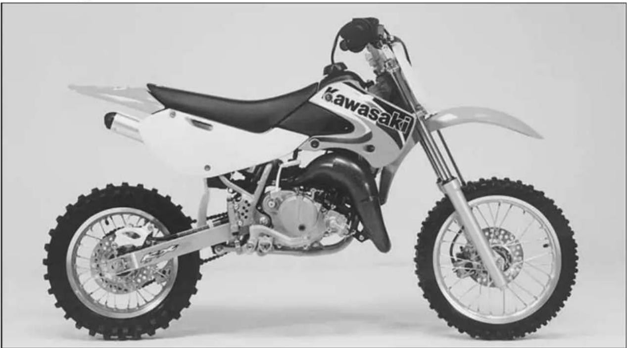
Black and white photo of a Kawasaki motorcycle with visible dynamics and tires (no text or symbols)KX65-A1RightSideView
natural_image
Black and white exterior view of a Kawasaki motorcycle with visible tracks, tires, and gear (no text or symbols on the bike body)GeneralSpecifications
| ItemsKX65-A1~ A2 | KX65-A3~ A6,A6F ~ ABF | |
| Dimensions | ||
| OverallLength1580mm1590mm | ||
| OverallWidth690mm(KX65-A1),730mm(KX65-A2)760mm | ||
| OverallHeight925mm(KX65-A1),935mm(KX65-A2)955mm | ||
| Wheelbase1 1 1 0 m m 1120mm | ||
| Road Clearance | 270 mm (KX65-A1), 280 mm (KX65-A2) | 305 mm |
| Seat Height | 720 mm (KX65-A1), 730 mm (KX65-A2) | 760 mm |
| Dry Mass | 53 kg | 57 kg (KX65-A3 ~ A8F) |
| Curb Mass | - | 60 kg (KX65A9F ~) |
| Front | 26.5kg | 28.5kg |
| Rear | 29.5kg | 31.5kg |
| FuelTankCapacity | 3.8L | ← |
| Engine | ||
| Type | 2-stroke, single cylinder, piston reed valve | ← |
| CoolingSystemLiquid-cooled | ← | |
| Bore and Stroke | 44.5 × 41.6 mm | ← |
| Displacement | 64 cm3 | ← |
| Compression Ratio | 8.4: 1 | ← |
| Carburetion System | MIKUNI VM24SS | ← |
| Starting System | Primary kick | ← |
| Ignition System | MAGNETO CDI | ← |
| Ignition Timing | 20.5° BTDC @6 000 r/min (rpm) | ← |
| 20.5°BTDC @7100r/min (rpm) (KX65A6F ~) | ||
| Spark Plug | NGK BR10EG (US) NGK B10EG | ← |
| NGKBR10EG (KX65A6F ~) | ||
| PortTiming | ||
| Intake: | ||
| Open | Full open | ← |
| Close | — | ← |
| Scavenging: | ||
| Open | 61.8° BBDC | ← |
| Close | 61.8° ABDC | ← |
| DURATION | 123.6° | ← |
| Exhaust: | ||
| Open | 91.5° BBDC | ← |
| Close | 91.5° ABDC | ← |
| DURATION | 183° | ← |
| LubricationSystem (Gasoline:Oil) | Petrolmix(32:1) | ← |
GeneralSpecifications
| ItemsKX65-A1~ A2 | KX65-A3~ A6,A6F ~ ABF | |
| DriveTrainPrimaryReductionSystem:TypeGear←ReductionRatio3.500(77/22)←ClutchTypeWet,multidisc←Transmission:TypeGearRatios:1st2nd3rd4th5th6thFinalDriveSystem:TypeReductionRatioOverall Drive RatioTransmissionOil:GradeViscosityCapacity | 6-speed, constant mesh, return shiftChaindrive3.538(46/13)13.416 @Top gearAPI SG, SH, SJ, SL or SM with JASO MA, MA1orMA2SAE 10W-400.5 L | ←←3.615 (47/13)13.703 @Top gear←←← |
| FrameTypeSteeringAngleCaster (Rake Angle)TrailFront Tire:SizeTypeRearTire:SizeTypeRimSize:FrontRearFrontSuspension:TypeWheel TravelRearSuspension:TypeWheel Travel | Tubular, semi-double cradle40°toeitherside26.5°60 mm60/100-14 30Mtube type80/100-12 41Mtube type14×1.4012 × 1.60Telescopic fork210 mmSwingarm (Uni-trak)225 mm | ←←←←←←←←←←←←←←←←←←←←←←←←←←←←←←←←←←←←←←←←←←←←←←←←←←←←←←←←←←←←←←←←←←←←←←←←←←←←←←←←←←←←←←←←←←←←←←←←←←←←→ |
1-8GENERALINFORMATION
GeneralSpecifications
| ItemsKX65-A1~ A2 | KX65-A3~ A6,A6F ~ ABF |
| BrakeType:FrontandRearSingledisc←EffectiveDiscDiameter:Front154.8mm←Rear146mm← |
Specificationsaresubjecttochangewithoutnotice, and may not apply to every country.
US:UnitedStatesModel
PeriodicMaintenanceChart
The maintenance must be done in accordance with this chart to keep the motorcycle in good running condition.
| FREQUENCY OPERATION | After each race(or 2.5hr.) | Every 3races (or7.5 hr.) | Every 5races (or12.5 hr.) | Every 10races (or25 hr.) | As required |
| Clutch-adjust | ● | ||||
| Clutchandfrictionplates-inspect† | ● | R | |||
| Throttlecable-adjust | ● | ||||
| Sparkplug-clean,gap† | ● | R | |||
| Aircleanerelement-clean | ● | ||||
| Aircleanerelement-replaceWhendamaged | |||||
| Carburetor-inspect/adjust | ● | ||||
| Transmissionoil-change | ● | ||||
| Pistonandpistonring-clean/inspect† | ● | R | |||
| Cylinderhead,cylinder-inspect | ● | ||||
| Mufflerbody-clean/inspect† | ● | ||||
| Mufflerbodypacking-change | ● | ||||
| Smallendbearing-inspect† | ● | R | |||
| Kickpedalandshiftpedal-clean | ● | ||||
| ExhaustpipeO-ring-replace | ● | ||||
| Enginesprocket-inspect† | ● | ||||
| Coolant-inspect† | ● | R | |||
| Waterhoses,connections-inspect† | ● | ||||
| Reedvalve-inspect† | ● | ||||
| Brakeadjustment-inspect† | ● | ||||
| Brakepadwear-inspect† | ● | ||||
| Brakefluidlevel-inspect† | ● | ||||
| Brakefluid-change | Every2years | ||||
| Brakemastercylindercupanddustseal-replaceEvery2years | |||||
| Brakecaliperfluidsealanddustseal-replaceEvery2years | |||||
| Brakehose-replaceEvery4years | |||||
| Brakehoses,connections-inspect† | ● | ||||
| Spoketightnessandrimrunout-inspect† | ● | ||||
| Drivechain-adjust | ● | ||||
| Drivechain-lubricate | ● | ||||
| Drivechainwear-inspect† | ● | ||||
| Drivechainslipperandguide-replaceWhendamaged | |||||
| Frontfork-inspect/clean | ● | ||||
| Frontforkoil-change | 1sttimeafter2races,thenevery5races | ||||
| Nuts,bolts,fasteners-inspect† | ● | ||||
| Fuelsystem-clean | ● | ||||
| Fuelhose-replace | Every4years | ||||
1-10GENERALINFORMATION
PeriodicMaintenanceChart
| OPERATION\FREQUENCY | After each race(or 2.5hr.) | Every 3races (or7.5 hr.) | Every 5races (or12.5 hr.) | Every 10races (or25 hr.) | As required |
| Fuelhoses,connections-inspect† | ● | ||||
| Steeringplay-inspect† | ● | ||||
| Steeringstembearing-grease | ● | ||||
| Rearsprocket-inspect† | ● | ||||
| Generallubrication-perform | ● | ||||
| Wheelbearing-inspect† | ● | ||||
| SwingarmandUni-Traklinkagepivots-grease | ● | ||||
| SwingarmandUni-Traklinkagepivots-inspect† | ● | ||||
| Rearshockoil-replace1sttimeafter2races,thenevery5races | |||||
†:Replace,add,adjust,cleanortorqueifnecessary.
R:Replace
TorqueandLockingAgent
Tightenallboltsandnutstothepropertorqueusinganaccuratetorquewrench.Ifinsufficiently tightened,aboltornutmaybecomedamaged,stripaninternalthread,orbreakandthenfallout.The followingtableliststhetighteningtorqueforthemajorboltsandnuts,andthepartsrequiringuseofa non-permanentlockingagentorliquidgasket.
When checking the tightening torque of the bolts and nuts, first loosen the bolt or nut by half a turn andthentightentospecifiedtorque.
Lettersusedinthe"Remarks"columnmean:
L: Applyanon-permanentlockingagenttothethreads.
Lh:Left-handThreads.
S: Tightenthefastenersfollowingthespecifiedsequence.
| Fastener | Torque | Remarks | ||
| N·m | kgf·mft·lb | |||
| FuelSystem | ||||
| RearFrameMountingBolts343.525 | ||||
| CarburetorClampScrews1.50.15 13in·lb | ||||
| Carburetor Holder Mounting Bolts | 8.8 | 0.90 | 78 in·lb | |
| AirCleanerHousingPlateNuts | 3.00.31 | 27in·lb | ||
| AirCleanerHousingMountingBolts | 8.80.90 | 78in·lb | ||
| ReedValveScrews | 9.8 | 1.0 | 87in·lb | |
| CoolingSystem | ||||
| Radiator Mounting Bolts | 8.8 | 0.90 | 78 in·lb | |
| Shroud Mounting Bolts | 8.8 | 0.90 | 78 in·lb | |
| Air Bleeder Bolt | 8.8 | 0.90 | 78 in·lb | |
| Water Pump Cover Bolts | 8.8 | 0.90 | 78 in·lb | |
| Water Pump Impeller Bolt | 8.3 | 0.85 | 73 in·lb | |
| Water Hose Clamp Screws | 1.5 | 0.15 | 13 in·lb | |
| Coolant Drain Plug (Water Pump) | 8.8 | 0.90 | 78 in·lb | |
| Water Pump Cover Fitting Bolts | 5.9 | 0.60 | 52 in·lb | |
| EngineTopEnd | ||||
| CylinderHeadNuts | 252.518 | |||
| SparkPlug | 262.619 | |||
| CylinderNuts | 252.518 | |||
| Muffler Mounting Bolts | 8.8 | 0.90 | 78 in·lb | L |
| ExpansionChamberDamperMountingBolt, Nut | 8.80.90 | 78in·lb | ||
| Inner Pipe Mounting Bolts | 5.9 | 0.6 | 52 in·lb | L |
| EngineRightSide | ||||
| Primary Gear Nut (KX65A6F ~) | 49 | 5.0 | 36 | Lh |
| Clutch Spring Bolts | 9.3 | 0.95 | 82 in·lb | |
| ClutchHubBolt | 646.547 | |||
| Ratchet Guide Bolt | 8.8 | 0.90 | 78 in·lb | |
| Ratchet Guide Screw | 5.2 | 0.53 | 46 in·lb | |
| Kick Pedal Bolt | 12 | 1.2 | 104 in·lb | |
| Right Engine Cover Bolts | 8.8 | 0.90 | 78 in·lb | |
| Oil Filler Cap | 1.5 | 0.15 | 13 in·lb | |
| Gear Set Lever Screw | 8.8 | 0.90 | 78 in·lb | |
TorqueandLockingAgent
| Fastener | Torque | Remarks | ||
| N·mkgf·mft·lb | ||||
| EngineRemoval/Installation | ||||
| EngineMountingNuts252.518 | ||||
| Engine Mounting Nuts (KX65-A3 ~) | 29 | 3.0 | 21 | |
| SwingArmPivotShaftNut697.051 | ||||
| EngineBottomEnd/Transmission | ||||
| CylinderStud | — | L(Planted Side) | ||
| CrankcaseBolts | 8.80.9078in·lb | |||
| ShiftPedalBolt | 8.80.9078in·lb | |||
| EngineOilDrainPlug | 202.015 | |||
| BearingRetainingScrews | 8.80.9078in·lb | |||
| ShiftDrumOperatingPlateBolt | 242.417 | L | ||
| Shift Drum Plate Mounting Screws | 5.2 | 0.53 | 46 in·lb | L |
| GearSetLeverScrew | 8.80.9078in·lb | |||
| FlywheelNut | 293.021 | |||
| Wheels/Tires | ||||
| FrontAxleNut | 798.058 | |||
| RearAxleNut | 798.058 | |||
| SpokeNipple | Not less than1.5 | Not less than0.15 | Not less than 13 in·lb | |
| FinalDrive | ||||
| RearAxleNut | 798.058 | |||
| RearSprocketBolts | 262.720 | |||
| Brakes | ||||
| CaliperMountingBolts(Front,Rear) | 252.518 | |||
| BrakeHoseBanjoBolts | 252.518 | |||
| Master Cylinder Clamp Bolts | 8.8 | 0.90 | 78 in·lb | S |
| Rear Master Cylinder Mounting Screws | 9.8 | 1.0 | 87 in·lb | |
| RearMasterCylinderPushRodLocknut181.813 | ||||
| Brake Disc Mounting Bolts (Front, Rear) | 9.8 | 1.0 | 87 in·lb | L |
| Caliper Bleed Valves (Front, Rear) | 7.8 | 0.80 | 69 in·lb | |
| BrakePedalMountingBolt | 252.518 | |||
| Brake Lever Adjuster locknut | 4.9 | 0.50 | 43 in·lb | |
| BrakePadBolts | 181.813 | |||
| Suspension | ||||
| FrontForkClampBolts(Upper) | 202.014 | |||
| FrontForkClampBolt(Lower) | 293.022 | |||
| ForkBottomAllenBolt | 202.014 | L | ||
| FrontForkTopPlug | 222.216 | |||
| SwingarmPivotShaftNut | 697.051 | |||
| RearShockAbsorberMountingBolt(Upper) | 394.029 | |||
| RearShockAbsorberMountingNut(Lower) | 343.525 | |||
| Tie-rodMountingNuts(Front,Rear) | 596.043 | |||
TorqueandLockingAgent
| Fastener | Torque | Remarks | ||
| N·mkgf·mft·lb | ||||
| RockerArmPivotNut838.561CaliperMountingBoltsRearFrameMountingBolts343.525 | 252.518 | |||
| SteeringSteeringStemHeadNut444.533SteeringStemNut2.90.3026in·lbHandlebarClampBoltsClutchLeverClampBoltsFrontForkClampBolts(Upper)FrontForkClampBolts(Lower)293.022 | 252.5188.80.9078in·lb202.015 | |||
| ElectricalSystemMagnetoCoverBolts8.80.9078in·lbFlywheelNutStatorPlateMountingScrewsIgnitionCoilMountingBoltsCDI Unit Mounting BoltsSparkPlug | 293.0214.90.5043in·lb8.80.9078in·lb8.8262.619 | 0.90 | 78 in·lb | |
The table below relating tightening torque to thread diameter, lists the basic torque the bolts and nuts. Use this table for only the bolts and nuts which do not require a specific torque value. All of the values are for use with dry solvent-cleaned threads.
BasicTorqueforGeneralFasteners
| Threadsdia. (mm) | Torque | ||
| N·m | kgf·m | ft·lb | |
| 5 | 3.4 ~ 4.9 | 0.35 ~ 0.50 | 30 ~ 43 in·lb |
| 6 | 5.9 ~ 7.8 | 0.60 ~ 0.80 | 52 ~ 69 in·lb |
| 8 | 14 ~ 19 | 1.4 ~ 1.9 | 10.0 ~ 13.5 |
| 10 | 25 ~ 34 | 2.6 ~ 3.5 | 19.0 ~ 25 |
| 12 | 44 ~ 61 | 4.5 ~ 6.2 | 33 ~ 45 |
| 14 | 73 ~ 98 | 7.4 ~ 10.0 | 54 ~ 72 |
| 16 | 115 ~ 155 | 11.5 ~ 16.0 | 83 ~ 115 |
| 18 | 165 ~ 225 | 17 ~ 23 | 125 ~ 165 |
| 20 | 225 ~ 325 | 23 ~ 33 | 165 ~ 240 |
1-14GENERALINFORMATION
SpecialToolsandSealants
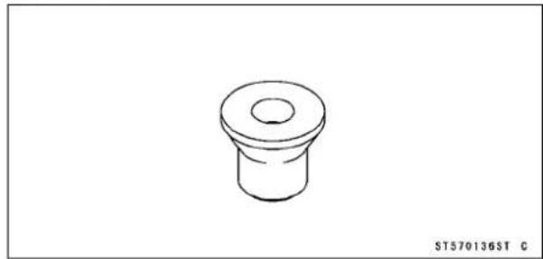
BearingPullerAdapter: 57001-136
natural_image
Simple line drawing of a mechanical component with a flanged top and central hole (no text or symbols)SteeringStemBearingDriver: 57001-137

natural_image
Line drawing of a cylindrical mechanical component with a textured top and flange (no text or symbols)InsideCirclipPliers: 57001-143

natural_image
Line drawing of a pair of pliers (no text or symbols)OutsideCirclipPliers: 57001-144

natural_image
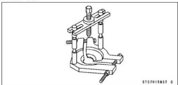
Line drawing of a pair of needle tips (no text or symbols)BearingPuller: 57001-158
natural_image
Technical line drawing of a mechanical clamp or clamping device (no text or symbols)ForkCylinderHolderHandle: 57001-183

natural_image
Simple line drawing of a T-shaped tool or rod with a base, no text or symbols present.FlywheelPuller, M12×1.75: 57001-252

natural_image
Technical line drawing of a mechanical clamp or fitting with threaded end and flange (no text or symbols)PistonPinPullerAssembly: 57001-910

natural_image
Technical line drawing of a cylindrical mechanical component with multiple bolted and threaded parts (no text or symbols)ForkCylinderHolderAdapter: 57001-1011
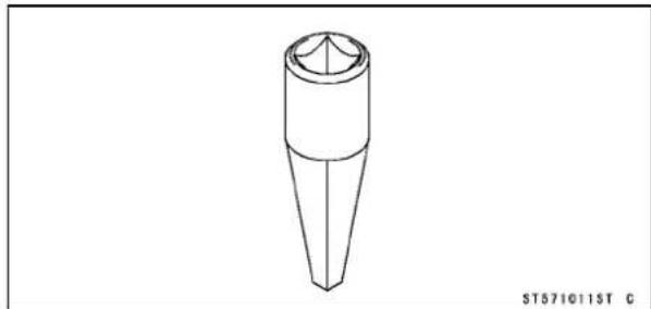
natural_image
Technical line drawing of a conical mechanical component (no text or symbols)OilSeal&BearingRemover: 57001-1058
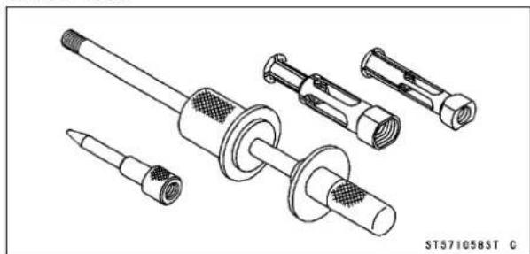
natural_image
Technical line drawing of a mechanical component assembly (no text or symbols)SpecialToolsandSealants
RimProtector:
57001-1063

natural_image
Five identical curved metal tools or clips arranged in a row, no text or symbols visible.BeadBreakerAssembly:
57001-1072
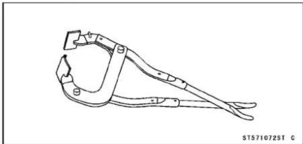
natural_image
Line drawing of a manual tool with clamps and handle (no text or symbols)HeadPipeOuterRacePressShaft:
57001-1075

natural_image
Technical line drawing of a mechanical component with threaded ends and a cylindrical shaft (no text or symbols)SteeringStemBearingDriverAdapter,29. :
57001-1092

natural_image
Simple line drawing of a cylindrical mechanical component (no text or symbols)SteeringStemNutWrench:
57001-1100

natural_image
Line drawing of a mechanical wrench tool (no text or symbols on the diagram itself)HookWrenchR37.5,R42:
57001-1101

natural_image
Technical line drawing of two mechanical wrenches (no text or symbols)HeadPipeOuterRaceDriver,46.5:
57001-1106

natural_image
Technical line drawing of a mechanical component with a flanged top and central hole (no text or symbols)HeadPipeOuterRaceRemoverID>37mm:
57001-1107

natural_image
Technical line drawing of a mechanical clamp or bracket component (no text or symbols)BearingDriverSet:
57001-1129
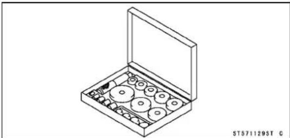
natural_image
Isometric line drawing of a box containing multiple circular components, no text or symbols presentForkOuterTubeWeight:
57001-1218

natural_image
Technical line drawing of a mechanical component with no visible text or symbols1-16GENERALINFORMATION
SpecialToolsandSealants
FrontForkOilSealDriver: 57001-1219

natural_image
Technical line drawing of a cylindrical mechanical component with internal cavities (no text or symbols)Jack:
57001-1238
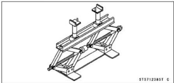
natural_image
Technical line drawing of a mechanical support structure (no text or symbols)ForkOilLevelGauge: 57001-1290

natural_image
Technical line drawing of a mechanical assembly with cylindrical components and threaded rods (no text or symbols)CrankcaseSplittingToolAssembly: 57001-1362

natural_image
Technical line drawing of a mechanical clamp or bracket assembly with four bolts and three pins (no text or symbols)HandTester: 57001-1394

natural_image
Technical line drawing of a mechanical housing or enclosure with internal components and mounting holes (no text or symbols)PeakVoltageAdapter: 57001-1415

natural_image
Pure electrical circuit lines without any symbolsCrankShaftJig: 57001-1439

natural_image
Technical line drawing of two mechanical components with mounting holes (no text or symbols)GraduatedCylinder&Tube: 57001-1584

natural_image
Technical line drawing of a U-shaped pipe fitting with two cylindrical components and a black-and-white striped section (no text or symbols)Flywheel&PulleyHolder: 57001-1605

natural_image
Technical line drawing of a mechanical clamp or bracket assembly with mounting holes and mounting points (no text or symbols)FuelLevelGaugeAdapter,M16×1:57001-1661
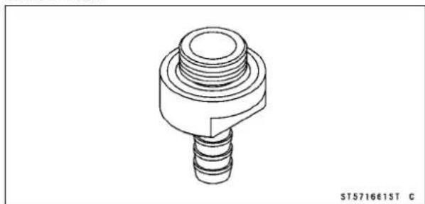
natural_image
Technical line drawing of a mechanical component with threaded and threaded sections (no text or symbols)SpecialToolsandSealants
LiquidGasket,TB1211:
56019-120
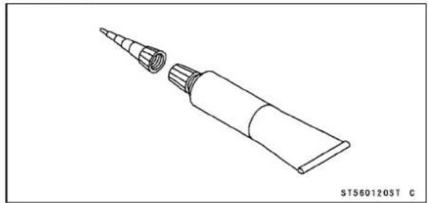
natural_image
Line drawing of a cylindrical tool with a pointed tip and a flanged end, shown without any text or symbols.LiquidGasket, TB1105B:
92104-002

natural_image
Line drawing of a cylindrical tool with a flanged tip and a side tab, shown without any text or symbols.
- ThrottleCable
- Carburetor
3.BreatherHose
4.AirVentHose - OverflowHose
- The hoses are passed from the left side of the engine through the clampin order of the air vent those, the overflow whose and the breather hose as shown in figure.
7.CDIUnit(KX65-A1\~A6)
8.Clamp
9.RubberDamper(Noteitsinstallingdirection.)
- ClutchCable
- EngineStopButtonLead
12.Band - Install the kickped also that it should be parallel to the frame as shown in figure.
14.KX65-A1\~A2
15.KX65-A3\~A6
Cable, Wire and Hose Routing

1.BreatherHose
2. Runthethrottlecableunderthebreatherhose.
3.Radiator
4.CDIUnit(KX65-A1\~A6)
5. Clamp(KX65-A1\~A6)
6.ThrottleCable
7. Clampashowninfigure.(Besuretheclampscrewpositionisinside.)
8. Clampashowninfigure.
9.CylinderHead
10.Cylinder
11.WaterPumpCover
12. EngineStopButtonLead(KX65A6F\~)

GB090503W4 C
- Clamp
2.CDIUnit(KX65-A1\~A6)
3.Band - Clampthemagnetoleadsattheupperpartoftheleftonthecarburetorholder.
5.MagnetoLeads
6.ShiftPedal
7.19±10mm(ShiftPedalPosition) - EngineStopButtonLead
- IgnitionCoil
- EngineStopButtonLeadGround
11.CDIUnitGroundLead
Cable, Wire and Hose Routing

GB090177W4 C
- FrontBrakeReservoir
2.BanjoBolts - Clamp
4.FrontBrakeDisk
5.BleedValves
6.FrontBrakeCaliper - RearBrakeCaliper
8.RearBrakeDisk - RearBrakeReservoir
10.RearBrakeMasterCylinder
11.Bendthecotterpinendbyalongthejointpin. - Whitepaintmark
KX65A6F\~

- ThrottleCable
- ClutchCable
3.Band - EngineStopButtonLead
-
Clamp
6.CDlunit
7.Band
8.CDIunitGro undLead -
Ignition Coil Primary Lead
10.IgnitionCoilGrou ndLead
11.IgnitionCoil
12.Band
13.ClamptheMagnet oLead
14.KX65A6F\~A8F
15.KX65A9F\~
FuelSystem
TableofContents
Exploded View.... 2-2
Specifications 2-4
Throttle Grip and Cable 2-5
Free Play Inspection 2-5
Free Play Adjustment.... 2-5
Throttle Cable Installation 2-6
Cable Lubrication 2-6
Cable Inspection 2-6
Carburetor 2-7
Idle Speed Inspection 2-7
Idle Speed Adjustment.... 2-7
Service Fuel Level Inspection 2-7
Service Fuel Level Adjustment 2-8
Carburetor Removal 2-9
Carburetor Installation.... 2-10
Fuel Inspection.... 2-11
Carburetor Disassembly 2-11
Carburetor Assembly 2-12
Carburetor Cleaning 2-13
Carburetor Inspection 2-13
Air Cleaner 2-15
Air Cleaner Housing Removal 2-15
Air Cleaner Housing Installation.... 2-15
Element Removal.... 2-15
Element Installation.... 2-15
Element Cleaning and Inspection 2-16
Fuel Tank 2-17
Fuel Tank Removal 2-17
Fuel Tank Installation 2-17
Fuel Tap Removal 2-17
Fuel Tap Installation 2-17
Fuel Tap Inspection.... 2-18
Fuel Tank and Tap Cleaning 2-18
Reed Valve 2-19
Reed Valve Removal 2-19
Reed Valve Installation 2-19
Reed Valve Inspection 2-19
Fuel Hose 2-20
FuelHosesandConnectionsCheck....2-20

GC020501W4 C
- ThrottleCable
2.ThrottleGrip - CarburetorHolder
4.CarburetorCap
5.Spring
6.Retainer
7.JetNeedleClip
8.JetNeedle
9.ThrottleValve
10.ChokeKnob
11.IdleAdjustingScrew
12.Spring
13.AirScrew
14.SlowJet
15.FloatValveNeedle
16.MainJet
17.Float
18.ReedValve
T1:8.8N·m(0.90kgf·m,78in·lb)
T2:1.5N·m(0.15kgf·m,13in·lb)
T3:9.8N·m(1.0kgf·m,87in·lb)
G:Applygrease.
O:Applyoil.
ExplodedView

1.FuelTankCap
2.FuelTank
3.FuelTap
4.AirCleanerHousing
5. Element
6.Frame
7.Holder
8.AirCleanerDuct
9.KX65A6F\~
T1:34N·m(3.5kgf·m,25ft·lb)
T2:8.8N·m(0.90kgf·m,78in·lb)
T3:3.0N·m(0.31kgf·m,27in·lb)
G:Applygrease.
O:High-qualityfoam-airfilteroil
GC02375BW4 C
Specifications
| Item | Standard | Service Limit | |
| KX65-A1 ~ A2 | KX65-A3 ~ | ||
| Throttle Grip Free Play and Cable | 2 ~ 3 mm | ← | - - - |
| Carburetor | |||
| Make/TypeMIKUNIVM24SS | ← - - - | ||
| MainJet | #230#190 | - - - | |
| ThrottleValveCutaway#2#1.5 | - - - | ||
| Jet Needle | 5HS59 | 5G SP68 | - - - |
| Jet Needle Clip Position | 3rd groove from the top | 3rd groove from the top | - - - |
| Needle Jet | O-0 | ← | - - - |
| Slow Jet | #40 | #25 | - - - |
| Air Screw | 2 (turns out) | 1 1/2 (turns out) | - - - |
| Main Air Jet | 0.8 (Pressed in) | ← | - - - |
| ServiceFuelLevel(belowthe BottomEdgeofthe Carburetor Body) | 0.5±1mm | ← - - - | |
| Float Height | 21.1 ±1 mm | ← | - - - |
| AirCleaner | |||
| ElementOil | High-qualityfoam-airfilteroil | - - - | |
| ReedValve | |||
| Reed Warp | - - - | 0.5 mm | |
Special Tools - Fuel Level Gauge Adapter M16 × 1: 57001-1661
GraduatedCylinder&Tube:57001-1584
ThrottleGripandCable
Ifthethrottlegriphasexcessivefreeplayduetocable stretchormis-adjustment,therewillbeadelayinthrottle response.Also,thethrottlevalvemaynotopenfullyatfull throttle.Ontheotherhand,ifthethrottlegriphasnoplay, thethrottlewillbehardtocontrol,andtheidlespeedwill beerratic.CheckthethrottlegripplayperiodicallyinaccordancewiththePeriodicMaintenanceChart,andadjustthe playifnecessary.
ThethrottlecableroutingisshowninCable, Wire and HoseRoutingintheGeneralInformationchapter.
FreePlayInspection
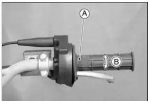
- Checkthethrottlegripfreeplay[B]bylightlyturningthe throttlegripAbackandforth.
★Ifthefreeplayisimproper,adjustthethrottlecable.
ThrottleGripFreePlay
Standard: 2\~3mm
FreePlayAdjustment
- LoosenthelocknutAattheupperendofthethrottle cable.
- Turntheadjuster[B]untiltheproperamountofthrottle gripfreeplayisobtained.
- Tightenthelocknut.
★ Ifthethrottlegripfreeplaycannotbeadjustedwiththe adjusterattheupperendofthethrottlecable,usethe cableadjusterAatthecarburetor.
- Pullthebootoffofthecarburetortop.Makethenecessary freeplayadjustmentatthelowercableadjuster,tighten thelocknut[B],andinstalltheboot.
- Turnthehandlebarfromsidetosidewhileidlingtheengine.Ifidlespeedvaries,thethrottlecablemaybepoorly routedoritmaybedamaged.

WARNING
Operation with improperly adjusted, incorrectly routedordamagedcablescouldresultinanunsafe ridingcondition. Followtheservicemanualtobe makesuretocorrectanyoftheseconditions.


ThrottleGripandCable
Throttle Cable Installation
- InstallthethrottlecableinaccordancewiththeCable, WireandHoseRoutingsectionintheGeneralInformationchapter.
- Aftertheinstallation,adjusteachcableproperly.

WARNING
Operationwithincorrectlyroutedorimproperlyadjustedcablescouldresultinanunsaferidingcondition.Besurethecablesareroutedcorrectlyand properlyadjusted.
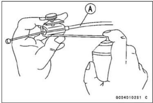
CableLubrication
Wheneverthecableisremoved,andinaccordancewith thePeriodicMaintenanceChart(seeGeneralInformation chapter),dothefollowing.
CableInspection
- Withthet hrottlecableAdisconnectedatbothends,the cableshouldmovefreelywithinthecablehousing.
★ Ifcablemovementisnotfreeafterlubricating,ifthecable isfra yed,orifthehousingiskinked,replacethecable.


Carburetor
Sincethecarburetorregulatesandmixesthefuelandair goingtotheengine,therearetwogeneraltypesofcarbure-tortrouble:toorichamixture(toomuchfuel),andtoolean amixture(toollittlefuel).Suchtroublecanbecausedby dirt,wear,maladjustment,orimproperfuellevelinthefloat chamber.Adirtyordamagedaircleanercanalsoalterthe fueltoairratio.
IdleSpeedInspection
- Starttheengineandwarmitupthoroughly.
- Withtheengineidling,turnthehandlebartobothsides.
★Ifhandlebarmovementchangestheidlespeed,thethrottlecablemaybeimproperlyadjustedorincorrectlyrouted,oritmaybedamaged.Besuretocorrectanyofthese conditionsbeforeriding(seeCable,WireandHoseRoutingintheGeneralInformationchapter).
WARNING
Operationwithimproperlyadjusted,incorrectly routedordamagedcablescouldresultinanunsafe ridingcondition.Followtheservicemanualtobe makesuretocorrectanyoftheseconditions.
- Checkidlespeed.
★Adjustitasneeded.
IdleSpeedAdjustment
- FirstturnintheairscrewAuntilitseatslightly,andback itout2turns(KX65-A1\~A2).
- FirstturnintheairscrewAuntilitseatslightly,andback out11/2turns(KX65-A3\~).
- Starttheengineandwarmitupthoroughly.
- Turntheidleadjustingscrew[B]toobtaindesiredidle speed. Ifnoidleispreferred,turnoutthescrew until the enginestops.
- Openandclosethethrottleafewtimestomakesurethat theidlespeedisasdesired. Readjustifnecessary.

ServiceFuelLevelInspection
WARNING
Gasoline is extremely flammable and can be explosiveundercertainconditions. Alwaysstopthe engineanddonotsmoke. Makesuretheareais wellventilatedandfreefromanysourceofflame orsparks;thisincludesanyappliancewithapilot light.
- TurnthefueltaptotheOFFposition.
- Removethefueltank(seeFuelTankRemoval).
Carburetor
- Removethecarburetor, and hold it in true vertical position on a stand. The fuel hose and carburetor cabledonot havetober removed to inspect the fuel level A.
- Putthefueltankonabench, and connect the fueltapto the carburetor using asuitable hose.
- Removethedrainplugfromthebottomofthefloatbowl, andscrewafuellevelgaugeadapter[B]intothedrain plughole.
- Connectofthegraduatedcylinder&tube[C]tofuellevel gaugeadapter.
SpecialTools-FuelLevelGaugeAdapterM16×1:57001 -1661
GraduatedCylinder&Tube:57001-1584
- Holdthegaugeverticallyagainstthesideofthecarburetorbodysothatthe"zero"line[D]isseveralmillimeters higherthanthebottomedge[E]ofthecarburetorbody.
- TurnthefueltaptotheONpositiontofeedfueltothe carburetor.
- Waituntilthefuellevelinthegaugesettles.
- Keepingthegaugevertical, slowly lower the gauge until the "zero" line is even with the bottom edge of the carburetorbody.

NOTE
○Donotlowerthe"zero"linebelowthebottomedgeof thecarburetorbody. Ifthegaugeisloweredandthen raisedagain, thefuellevelmeasureshowssomewhat higherthantheactualfuellevel. Ifthegaugeislowered toofar, dumpthefueloutofitintoasuitableconta iner andstarttheprocedureoveragain.
- Readthefuellevelinthegaugeandcompareittothe specification.
ServiceFuelLevel(belowthebottomedgeofthecarb. body)
Standard: 0.5 ± 1 mm
★ Ifthefuellevelisincorrect,adjustit.
- TurnthefueltaptotheOFFpositionandremovethefuel levelgauge.
- Installthedrainplugonthebottomofthefloatbowl.
ServiceFuelLevelAdjustment
WARNING
Gasoline is extremely flammable and can be explosive under certain conditions. Always stop the engine and donotsmoke. Makes sure the area is well-ventilated and free from any source of flame or sparks; this includes any appliance with a pilot light.
- Removethecarburetor, and drain the fuel into as suitable container.
- Removethefloatbowl.
Carburetor
- DriveoutthepivotpinAandremovethefloat[B].
- BendthetangAonthefloatarmveryslightlytochange thefloatheight.Increasingthefloatheightlowersthefuel levelanddecreasingthefloatheightraisesthefuellevel.
FloatHeight
Standard:
21.1±1mm


natural_image
Technical line drawing of a mechanical clamp or bracket assembly with labeled component A (no text or symbols beyond label)NOTE
○ FloatheightAisthedistancefromthefloatbowlmatingsurface[B]ofthecarburetorbody(withthegasket removed)tothetopofthefloat[C].Measuretheheight withthecarburetorupsidedown.
○ Donotpushtheneedlerod[D]induringthefloatheight measurement.
- Assemblethecarburetor, andrecheckthefuellevel.
★Ifthefu ellevelcannotbeadjustedbythismethod,the floatorthefloatvalveisdamaged.
CarburetorRemoval

WARNING
Gasolineisextremelyflammableandcanbeexplosiveundercertainconditions.Alwaysstopthe engineanddonotsmoke.Makesuretheareais wellventilatedandfreefromanysourceofflame orsparks;thisincludesanyappliancewithapilot light.
- TurnthefueltaptotheOFFpositionandpullthefuelhose offthetap.
- Screwintheupperandlowerthrottlecableadjustersto givethecableplentyofplay(seeThrottleCableAdjustment).
- LoosenthecarburetorclampscrewsAandremovethe carburetorfromtheendoftheaircleanerduct, and then pullitoutofthecarburetorholderfromthevehicleleftside.


natural_image
Close-up of a mechanical assembly with labeled component A (no readable text or symbols)Carburetor
- UnscrewthecarburetorcapA, and pullout the throttle valve assembly[B].
NOTICE
Ifthethrottlevalveisleftattachedtothecable,wrap itinacleanclothtoavoiddamage.
- Afterremovingthecarburetor, pushaclean, lint-freetowel intothecarburetorholderandtheaircleanerducttokeep dirtorotherforeignmaterialfromentering.

WARNING
Ifdirtordustisallowedtopassthroughintothe carburetor,thethrottlemaybecomestuck,possibly causingaccident.Replaceheaircleanerelement accordingtothemaintenancechart.
NOTICE
Ifdirtgetsthroughintotheengine,excessiveenginewearandpossiblyenginedamagewilloccur.
Carburetor Installation
- Beingcarefulnottobendorotherwisedamagethejet needle, alignthegrooveAinthethrottlevalvewiththe guidepin[B]inthecarburetorbody.
○Checktoseethatthethrottlevalvegoesallthewaydown intothecarburetorbody, and slidessmoothly.
- FittheridgeAintothenotch[B]onthecarburetorholder.
- Tightenthecarburetorclampscrewsontheaircleaner ductandcarburetorholdersecurely.
- Routetheairventhoseandoverflowhosethroughthe clamponthecrankcase(seeCable, WireandHoseRoutingSectionintheGeneralInformationchapter).
NOTICE
Alwayskeepthehosesfreefromobstruction,and makesuretheydonotgetpinchedbythechainor shockabsorber.

natural_image
Close-up of a mechanical component with labeled parts A and B, showing internal components and wiring (no readable text or symbols beyond labels)

Carburetor
- TurnthefueltaptotheONposition, and check for fuel leakage from the carburetor.

WARNING
Fuelspilledfromthecarburetorishazardous.
- Adjust the following items if necessary: Throttle Cable(seethischapter) IdleSpeed(seethischapter)
FuelInspection

WARNING
Gasolineisextremelyflammableandcanbeexplosiveundercertainconditions.Alwaysstopthe engineanddonotsmoke.Makesuretheareais well-ventilatedandfreefromanysourceofflame orsparks;thisincludesanyappliancewithapilot light.
- TurnthefueltaptotheOFFposition.
- Removethecarburetor.
- Placeasuitablecontainerbeneaththecarburetor.
- RemovethedrainplugAfromthebottomofthefloat bowlandcheckforwaterordirtinthefuel.
★Ifanywaterordirtcomesout,cleanthecarburetor,fuel tapandfueltank(seethischapter). - Installthedrainplugonthefloatbowl, andtightenitsecurely.
• Installthecarburetor.

CarburetorDisassembly

WARNING
Gasolineisextremelyflammableandcanbeexplosiveundercertainconditions.Alwaysstopthe engineanddonotsmoke.Makesuretheareais wellventilatedandfreefromanysourceofflame orsparks;thisincludesanyappliancewithapilot light.
- Removethecarburetor(seethischapter).
- Disassemblethethrottlevalveassemblyasfollows.
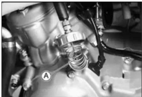
○HoldthethrottlevalvereturnspringAcompressed, take outtheretainer[B], and freethethrottlecablebyslidingit throughtheslot.

Carburetor
○Slidethejetneedleoutofthethrottlevalve.
○ PulloutthesnapringA, andremovethethrottlicable from thecarburetorcap[B].
• Disassemblethecarburetorbody.
ChokePlungerAssemblyA
IdleAdjustingScrew, SpringandO-ringB
AirScrewandSpringC
• Disassemblethecarburetorbodybottomend.
FloatBowlA
Gasket[B]
PivotPinC
Float[D]
FloatValve[E]
NeedleJet[F]
PlasticHolder[G]
PilotJet[H]
MainJet[I]
CarburetorAssembly
- Cleanthedisassembledparts(seethischapter).
NOTICE
Donotovertightenthejets. They could bedamaged requiring replacement.
- Replacethefloatbowlgasketwithanewoneifitisdeterioratedordamaged.
- BesuretoinstalltheretainerA.


natural_image
Close-up mechanical assembly showing springs and components (no visible text or symbols)Carburetor
CarburetorCleaning
WARNING
Gasolineandlow-flashpointsolventscanbe flammable and/or explosive and causes severe burns. Cleanthecarburetorinawellventilated area, and take care that there are no sparks or flame any where near the working area; this includes any appliance with a pilot light. Donot use gasoline or alow-flashpointsolvent to clean the carburetor.
- MakesurethefueltapisintheOFFposition.
- Removethecarburetor.
- Drainthefuelinthecarburetor.
- Disassemblethecarburetor.
NOTICE
Donotusecompressedaironanassembledcarburetor,thefloatmaybeformedbythepressure. Removeasmanyrubberorplasticpartsfromthe carburetoraspossiblebeforecleaningthecarburetorwithacleaningsolution.Thiswillprevent damageordeteriorationoftheparts.Donotuse astrongcarburetorcleaningsolutionwhichcould attacktheplasticparts;instead,useamildhigh flash-pointcleaningsolutionsafeforplasticparts. Donotusewireoranyotherhardinstrumentto cleancarburetorparts,especiallyjets,astheymay be damaged.
- Immerseallthemetalpartsinacarburetorcleaningsolution.
- Rinsetheparts inwater.
- Afterthepartsarecleaned, drythemwithcompressedair.
- Blowthroughtheairandfuelpassageswithcompressed air.
- Assemblethecarburetor, and installitonthemotorcycle.
CarburetorInspection
WARNING
Gasolineisextremelyflammableandcanbeexplosive under certain conditions. Always stop the engineandonotsmoke.Ma kesuretheareais well-ventilatedandfreefromanysourceofflame or sparks; this includes any appliance with a pilot light.
Carburetor
- Removethecarburetor.
- Beforedisassemblingthecarburetor, checkthefuellevel (seeFuelLevelInspection).
★ Ifthefuellevelisincorrect, inspecttherestofthecarburetorbeforecorrectingit. - Pullthecarburetorcabletocheckthatthethrottlevalve Amovessmoothlyandreturnsbyspringpressure.
★ Ifthethrottlevalvedoesnotmovessmoothly.Replace the carburetor.
• Disassemblethecarburetor. - Cleanthecarburetor.
-
CheckthetaperedportionAofthepilotscrew[B]for wearordamage.
★ Ifthepilotscrewiswornordamagedonthetaperedportion, it will prevent the engine from midlings smoothly. Replace it. -
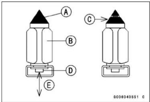
Removethefloatvalveneedle[B].
- ChecktheplastictipAforwear.
★ Iftheneedleiswornasshown[C],replacethevalveneedle. -
Pushtherod[D]inthevalveneedle,thenpushandrelease[E]it.
★ Iftheroddoesnotcomeoutfullybyspringtension,re-placethevalveneedle. -
Removetheslowjet.
- Checktheslowjetforanydamage.
★ Iftheslowjetisdamaged, replaceitwithanewone. - Removethethrottlevalveandjetneedle.
- Inspecttheoutsideofthethrottlevalveforscratchesandabnormalwear.
★ Ifitisbadlyscratchedorworn, replacethethrottlevalve. - Inspecttheinsideofthecarburetorbodyforthesesame faults.
★ Ifitisbadlyscratchedorworn, replacetheentirecarburetor. - Checkthejetneedleforwear.
★ Awornjetneedleshouldbereplaced. - Cleanthefuelandairpassageswithahighflash-point solventandcompressedair.

AirCleaner
AirCleanerHousingRemoval
- Remove:
RadiatorShrouds
SideCovers
Seat
RearFender
RearFlap
RearFrameMountingBoltsA
RearFrame[B]
AirCleanerHousingMountingBolts[C]
- Loosentheaircleanerductclamp[D].
- Removetheaircleanerhousing[E].
AirCleanerHousingInstallation
- Installationisthereverseoftheremoval.
- Tightentherearframemountingbolts.
Torque-RearFrameMountingBolts:34N·m(3.5kgf·m,25ft·lb)
AirCleanerHousingPlateNuts:3.0N·m(0.31 kgf·m,27in·lb)
AirCleanerHousingMountingBolts:8.8N·m (0.90kgf·m,78in·lb)
ElementRemoval
- Removetheseat.
- RemovethewingboltAandpullouttheelement[B].
- Stuffaclean, lint-freetowel into the carburetor sonodirt is allowed to enter the carburetor.
- Wipeouttheinsideoftheaircleanerhousingwithaclean damptowel.
NOTICE
Checkinsideoftheinlettractandcarburetorfor dirt.lfdirtispresent,cleantheintakettractandcarburetorthoroughly.Youmayalsoneedtoreplace theelementandsealthehousingandintakettract.
ElementInstallation
- Wheninstallingtheelement,coatthelipoftheelement with a thick layer of all purpose grease A to assure a completesealagainsttheaircleanerelementbase.Also, coatthebasewherethelipoftheelementfits.


natural_image
Close-up of a mechanical component with labeled parts A and B (no readable text or symbols beyond labels)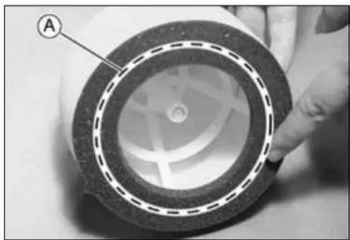
natural_image
Close-up of a cylindrical mechanical component with concentric rings and a labeled section (A), being handled by a hand (no text or symbols beyond label)AirCleaner
• InstalltheelementA.
○Theelementtab[B]positionisputonwhicheverofthe holder.

ElementCleaningandInspection
NOTE
○Industryareas, theelementshouldbecleanedmore frequentlythanrecommendedinterval.
○Afterridingthroughrainoronmuddyroads,theelement shouldbecleanedimmediately.
○Sincerepeatedcleaningopenstheporesoftheelement,replaceitwithanewoneinaccordancewiththe PeriodicMaintenanceChart. Also,ifthereisabreakin theelementmaterialoranyotherdamagetotheelement,replacetheelementwithanewone.

WARNING
Gasolineandlow-flashpointsolventscanbe flammable and/or explosive and causes severe burns. Clean the element in a well ventilated area, and take care that there is nospark or flame any-where near the working areas. Donot use gasoline or low flash points olvent st o clean the element.
- Removetheaircleanerelement, and separate the elementA from the frame[B].
- Cleantheelementinabathofahighflash-pointsolvent usingasoftbristlebrush.Squeezeitdryinacleantowel. Donotwringtheelementorblowitdry;theelementcan bedamaged.
- Checkallthepartsoftheelementforvisibledamage.
★ Ifanyofthepartsoftheelementaredamaged, replace them. - Aftercleaning, saturatetheelementwithahigh-quality foam-air-filteroil, squeezeouttheexcess, thenwrapitin acleanragandsqueezeitasdryaspossible. Becareful nottotearthespongefilter.
- Assembletheelement.
- Removethetowelfromthecarburetor.
• Installtheelement.

natural_image
Two 3D-printed mechanical components with labeled parts (A and B), no visible text or symbols on the parts themselves.FuelTank
FuelTankRemoval

WARNING
Gasolineisextremelyflammableandcanbeexplosiveundercertainconditions.Alwaysstopthe engineanddonotsmoke.Makesuretheareais well-ventilatedandfreefromanysourceofflame orsparks;thisincludesanyappliancewithapilot light.
- Remove:
RadiatorShrouds
Seat
- TurnthefueltaptotheOFFposition.
- Pullthefuelhoseoffthefueltap.
- RemovethefueltankmountingboltAandband[B].
- Removethefueltank[C].
- Drainthefueltank.
FuelTankInstallation
- ChecktherubberdamperAontheframe.
★Ifthedamperisdamagedordeteriorated,replaceit. - InstalltherubberdamperAnotingitsinstallingdirectionasshown.
- Besurethefuelhoseisclampedtothefueltaptoprevent leaks.
- Insertthefueltankbreatherhoseoutletendintothenumberplatehole.
FuelTapRemoval
- Removethefueltankanddrainit.
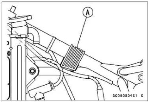
- Removethemounti ngboltsAandtakeoutthefueltap [B].


FuelTapInstallation
- BesuretheO-ringisingoodconditiontopreventleaks.
- Besuretoclampthefuelhosetothetaptopreventleaks.
FuelTank
FuelTapInspection
- Removethefueltap.
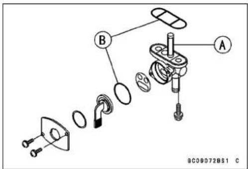
- CheckthefueltapfilterscreenAforanybreaksordeterioration.
★ Ifthefueltapscreenhaveanybreaksorisdeteriorated, it mayallowdirttoreachthecarburetor, causingpoorrunning. Replacethefueltap.
★ Ifthefueltapleaks, orallowsfueltoflowwhenitisatOFF position, replacethedamagedO-ring[B]. KX65A6F\~ [C]

FuelTankandTapCleaning
WARNING
Gasoline and low-flash points solvent scan be flammable and/or explosive and causes severe burns. Clean the tank in well-ventilated area, and take care that there are no sparks or flame any-where near the working area. Donot use gasoline or low-flash points solvent st o clean the tank.
- Removethefueltankanddrainit.
- Poursomehighflash-point solventintothefueltankand shakethetanktoremovedirtandfueldeposits.
- Pourthesolventoutofthetank.
- Removethefueltapfrom thetankbytakingoutthebolts.
- Cleanthefueltapfilterscreeninahighflash-pointsolvent.
- Pourhighflash-po intsolventthroughthetapinallever positions.
- Drythetankandtapwithcompressedair.
• Installthetap inthetank.
• Installthefueltank.
ReedValve
ReedValveRemoval
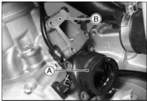
- RemovethecarburetorholdermountingboltsandcarburetorholderA.
- Removethereedvalve[B]outofthecylinder.
ReedValveInstallation
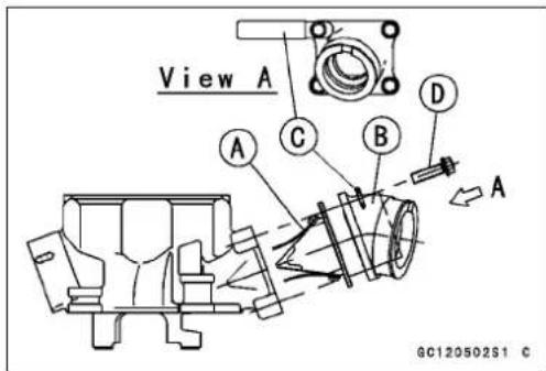
- Whenthereedorstoparereplaced, installthereedA andstop[B] ontothereedvalveholder[C], aligningthe chamferedcorner[D] ofthereedwiththatofthereedstop.
Torque-ReadValveScrews:9.8N·m(1kgf·m,87in·lb)
- InstallthereedvalveAandcarburetorholder[B]. - Besuretheclamp[C]isinhorizontalandtorquethecarburetorholdermountingbolts[D].
Torque-CarburetorHolderMountingBolts:8.8N·m(0.90 kgf·m,78in·lb)

ReedValveInspection
- Inspectthereedsforcracks,folds,orothervisibledamage.
★ If there is any doubt to the condition of areed, replace thereof valve part with anewone.
★lfareedbecomeswavy,replacethevalvepartwithanew oneevenifitswarpislessthantheservicelimit. - Measure the clearance between thereedA and holder [B], and check thereed warpasshown.
★ Ifanyoneoftheclearancemeasurementsexceedsthe servicelimit,replacevalvepartwithanewone.
ReedWarp
ServiceLimit: 0.5mm

FuelHose
FuelHosesandConnectionsCheck
○ Checkthefuelhoseperiodicallyinaccordancewiththe PeriodicMaintenanceChart, and ifthemotorcycle is not properly handled, the insidethefuelline can cause fuel to leak A or the hosetoburst. Removethefueltank and checkthefuelhose.
★Replacethefuelhoseifanyfraying,cracks[B]orbulges [C]arenoticed.
- Check that the hoses are securely connected and clamps are tightened correctly.
- Wheninstalling, routethehosesaccordingtoCable, Wire and HoseRoutingsectionintheGeneralInformation chapter.
- Wheninstallingthefuelhoses, avoidsharpbending, kinking, flatteningortwisting, and routethefuelhoses with a minimumofbendingsothatthefuelflowwillnotbeobstructed.
★Replacethehoseifithasbeensharplybentorkinked.

CoolingSystem
TableofContents
Exploded View.... 3-2
Specifications 3-3
Coolant 3-4
Coolant Level Inspection.... 3-4
Coolant Deterioration Inspection.... 3-4
Coolant Draining 3-5
Coolant Filling 3-5
Air Bleeding.... 3-6
Cooling System Pressure Testing 3-6
Cooling System Flushing 3-7
DisassemblyandAssemblyPrecautions....3-8
Water Pump 3-9
Water Pump Cover Removal 3-9
Water Pump Cover Installation 3-9
Impeller Removal 3-9
Impeller Installation 3-9
Impeller Inspection 3-9
Water Pump Shaft Removal 3-10
Water Pump Shaft Installation 3-10
Oil Seal Removal 3-10
Oil Seal Installation 3-10
Radiator 3-12
Radiator Removal 3-12
Radiator Installation 3-12
Radiator Inspection 3-12
Cap Inspection 3-13
Filler Neck Inspection.... 3-13
WaterHoses,BreatherHoseInspection....3-13
WaterHoses,BreatherHoseInstallation....3-13

GD02073BW4 C
- Radiator
2.RadiatorCap - WaterPumpCover
4.DrainPlug
5.Impeller
6.OilSeal(Short)
7.OilSeal(Long)
8.Bearing
9.WaterPumpGear
10.RightEngineCover
11.CylinderHead
12.Cylinder
13.AirBleederBolt
T1:8.8N·m(0.90kgf·m,78in·lb)
T2:8.3N·m(0.85kgf·m,73in·lb)
T3:5.9N·m(0.60kgf·m,52in·lb)
T4:1.5N·m(0.15kgf·m,13in·lb)
G:Applygrease.
M:Applymolybdenumdisulfidegrease.
Specifications
| ItemStandard | |
| CoolantTypeColorGreenMixedratioTotalamount0.4L | PermanenttypeantifreezeforaluminumenginesandradiatorsSoftwater50%,coolant50% |
| RadiatorCap relief pressure | 108 ~ 137 kPa (1.1 ~ 1.4 kgf/cm2, 16 ~ 20 psi) |
SpecialTools-BearingDriverSet:57001-1129
OutsideCirclipPliers:57001-144
3-4COOLINGSYSTEM
Coolant
Check the coolant level each day before riding the motor-cycle, and replenish coolant if the level is slow. Changethe coolant in accordance with the Periodic Maintenance Chart (see General Information chapter).

WARNING
Hotenginecoolantcancauseseriousburns. To avoidburns, donotremovetheradiatorcaportry toinspectthecoolantlevelorchangethecoolant whentheengineisstillhot. Waituntilcoolsdown.
CoolantLevelInspection
NOTE
○Checkthelevelwhentheengineiscold(roomorambienttemperature).
- Situatethemotorcyclesothatisperpendiculartothe ground.
- RemovetheradiatorcapA.
NOTE
○Removetheradiatorcapintwosteps.Firstturnthe capcounterclockwisetothefirststopandwaittherefor afewseconds.Thenpushdownandturnitfurtherin thesamedirectionandremovethecap.
- Checkthecoolantlevel.ThecoolantlevelAshouldbe atthebottomofthefillerneck[B].
★ Ifthecoolantlevelislow, addcoolantthroughthefiller openingtothebottomofthefillerneck.Installthecap.
RecommendedCoolant:
Permanent type of antifreeze (softwater and ethylene glycol plus corrosion and trustinhibitor chemicals for aluminum engines and radiators)
WaterandCoolantMixtureRatio:
1:1(water50%,Coolant50%)
Totalamount:0.4L

natural_image
Close-up of a mechanical component with a labeled section A pointing to a circular feature (no readable text or symbols)
CoolantDeteriorationInspection
- Visuallyinspectthecoolant.
★ Ifwhitishcotton-likewaftsareobserved,aluminumparts inthecoolingsystem arecorroded. Ifthecoolantis brown,ironorsteelpartsarerusting.Ineithercase,flush thecoolingsystem.
★ Ifthecoolantgivesoffanabnormalsmell, checkfora coolingsystemleak. It may be caused by exhaust gas leaking into the coolingsystem.
Coolant
CoolantDraining
Thecoolantshouldbechangedperiodicallytoensure longenginelife.

WARNING
Coolantcanbeextremelyhotandcausesevere burns,istoxicandveryslippery.Donotremove theradiatorcaporattempttochangethecoolant whentheengineishot;allowitcoolcompletely. Immediatelywipeanyspilledcoolantfromtires, frame,engineorotherpaintedparts.Donotingest coolant.
- Removetheradiatorcap.
NOTE
○Removetheradiatorcapintwosteps.Firstturnthe capcounterclockwisetothefirststopandwaittherefor afewseconds.Thenpushdownandturnitfurtherin thesamedirectionandremovethecap.
- PlaceacontainerunderthecoolantdrainplugA, and drainthecoolantfromtheradiatorandenginebyremovingthedrainplugonthewaterpumpcover.Immediately wipeorwashoutanycoolantthatspillsontheframe,engine,orwheel.
- Inspecttheoldcoolantforvisualevidenceofcorrosion andabnormalsmell(seeCoolantDeteriorationInspection).
CoolantFilling
NOTICE
Usecoolantcontainingcorrosioninhibitorsmade specificallyforaluminumenginesandradiatorsin accordancewiththeinstructionofthemanufac-turer.Softordistilledwatermustbeusedwiththe antifreeze(seebelowforantifreeze)inthecooling system.Ifhardwaterisusedinthesystem,it causescaleaccumulationinthewaterpassages, and considerably reduces the efficiency of the coolingsystem.
RecommendedCoolant
| Type: | Permanenttypeantifreeze(soft waterandethyleneglycolplus corrosionandrustinhibitor chemicalsforaluminumengines andradiators) |
Color: Green
MixedRatio: Softwater50%,Coolant50%
FreezingPoint: -35^(-31^)
TotalAmount: 0.4L
• Installthecoolantdrainplug.
○Replacethegasketwithanewone.
Torque- CoolantDrainPlug(WaterPump):8.8N·m(0.90 kgf·m,78in·lb)
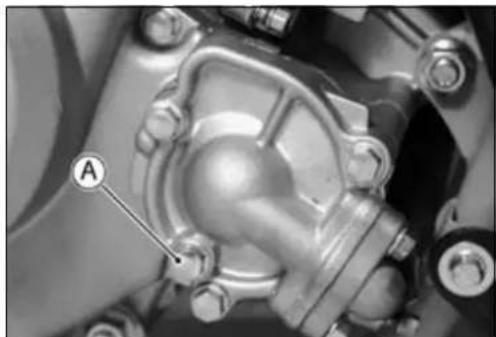
natural_image
Close-up mechanical component with labeled section A (no readable text or symbols beyond label)Coolant
- Filltheradiatoruptothebottomoftheradiatorfillerneck [B]withcoolantA,andinstallthecap,turningitclockwise about1/4turn.
NOTE
○Pourinthecoolantslowlysothatitcanexpeltheair fromtheengineandradiator. Theradiatorcapmustbe installedintwosteps.Firstturnthecapclockwisetothe firststop.Thenpushdownonitandturnittherestof theway.
- Checkthecoolingsystemforleaks.
AirBleeding
- Bleedtheairfromthecoolingsystemasfollows.
○LoosentheairbleederboltAonthecylinderheaduntil thecoolantbeginstoflowouttheairbleederbolthole(that is,untilalltheremainingairhasbeenforcedout).
○ Tightentheairbleederbolt.
Torque-AirBleederBolt:8.8N·m(0.90kgf·m,78in·lb)
○ Starttheengine withtheradiatorcapremovedandrunit untilnomoreairbubblesAcanbeseeninthecoolant.
○Tapthecoolinghosestoforceanyairbubblescaught inside.
○Stoptheengineandaddcoolantuptothefillerneck.
- Checkthecoolingsystemforleaks.
• Installtheradiatorcap.
○ Theradiatorcapmustbeinstalledintwosteps.Firstturn thecapclockwisetothefirststop.Thenpushdownonit andturnittherestoftheway.
CoolingSystemPressureTesting
NOTICE
Duringpressuretesting, donotexceedthepres- sureforwhichthesystemisdesignedtowork. The maximumpressureis123kPa(1.25kgf/cm², 18psi).
- Removetheradiatorcap, and installacoolingsystem pressuretesterAandadapter[B]ontheradiatorfiller neck[C].
NOTE
○Wettheadaptercapsealingsurfaceswithwateror coolanttopreventpressureleaks.
- Builduppressureinthesystemcarefullyuntilthepressurereaches123kPa(1.25kgf/cm²,18psi).
- Watchthegaugeforatleast6seconds.Ifthepressure holdssteady,thecoolingsystemisallright.
- Removethepressuretester,replenishthecoolant,and installtheradiatorcap.
★ If the pressuredrops and no external source is found, check for internal leaks. Check the cylinder headgasket for leaks.
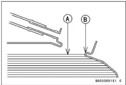

natural_image
Close-up of a mechanical component with labeled parts (A and 9134), no readable text or symbols beyond labels

Coolant
CoolingSystemFlushing
Overaperiodoftime, thecoolingsystem accumulates rust, scale, and lime in the water jacket and radiator. When this accumulation is suspected or observed, flush the coolingsystem. If this accumulation is not removed, it will clog up the water passages and considerably reduce the efficiency of the coolingsystem.
- Drainthecoolingsystem.
- Fillthecoolingsystemwithfreshwatermixedwithaflushingcompound.
NOTICE
Avoidtheuseofaflushingcompoundwhichis harmfultothealuminumengineandradiator. Carefullyfollowtheinstructionssuppliedbythe manufacturerofthecleaningproduct.
- Warmuptheengine, and runitat normal operating temperature for about ten minutes.
- Stoptheengine, and drain the coolingsystem after the coolant cools down.
- Fillthesystemwithfreshwater.
- Warmuptheengineanddrainthesystemafterthe coolantcoolsdown.
- Repeat the previous wostepsoncemore.
- Fillthesystemwithapermanenttypecoolant,andbleed theairfromthesystem(seeAirBleeding).
3-8COOLINGSYSTEM
Disassembly and Assembly Precautions
- Priorodisassemblyofcoolingsystemparts(radiator, pump,etc),waituntilhecoolantcoolsdown,andthen drainthecoolant.
- Afterassembling and filling the system with coolant, bleed any air from the system.
WaterPump
Water Pump Cover Removal
- Drain the coolant (see Coolant Draining).
- Loosen the water hose clamps A, and disconnect the water hoses on the water pump cover [B].
- Unscrew the cover bolts [C], and remove the water pump cover.

Water Pump Cover Installation
- Replace the pump cover gasket with a new one.
● Tighten the water pump cover bolts and clamps.
Torque-WaterPumpCoverBolts:8.8N·m(0.90kgf·m,78in·lb)
- Fill the cooling system (see Coolant Filling).
- Bleed the air from the cooling system.
Impeller Removal
- Drain the coolant (see Coolant Draining).
- Remove the cover bolts and take out the water pump cover from the right engine cover with the water hoses attached.
- Remove the water pump impeller bolt A, and take out the impeller [B] and washer.

Impeller Installation
- Tighten the water pump impeller bolt. Torque-WaterPumplm pellerBolt:8.3N·m(0.85kgf·m,73 in·lb)
Impeller Inspection
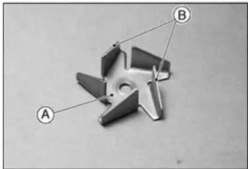
● Visually check the impeller A.
★If the surface is corroded, or if the blades [B] are damaged, replace the impeller.
WaterPump
WaterPumpShaftRemoval
- Remove:
RightEngineCover(seeEngineRightSidechapter) - RemovethecirclipA, and pulloff the primary gear[B]. Special Tool - Outside Circlip Pliers: 57001-144
KX65A6F\~:
- RemovetheprimarygearB.
- Pulloutthewaterpumpshaft[C]towardinsideoftheright enginecover.
WaterPumpShaftInstallation
- Topreventtheoilseallipsfrompeeling,applyamolybdenumdisulfidegreaseAtothewaterpumpshaft[B]and insertitintotheoilseals[C]fromtheinsideoftheright enginecover[D].
NOTICE
Besuretoapplyamolybdenumdisulfidegrease tothewaterpumpshaftwheninstalling.Ifitisinstalleddry,thesealsmaywearexcessively.
- Replacethecirclipfortheprimarygearwithanewone.
SpecialTool-OutsideCirclipPliers:57001-144 - Instaltheimpellerandchecktoseethattheimpellerturn freely.
OilSealRemoval
- Remove:
Impeller(seethischapter)
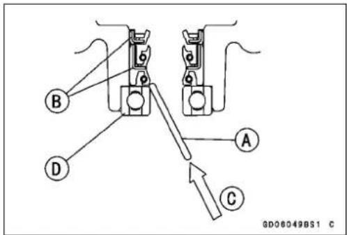
RightEngineCover(seeEngineRightSidechapter) - Toremovetheoilseals. Insertametalrodintotheright enginecoverfromtheoppositesideoftheimpeller, and tapevenlyaroundthebottomoftheseal.
AMetalRod
[B]OilSeals
[C]Tap
[D]BallBearing
OilSealInstallation
NOTICE
If the oil seal or ball bearing is removed, replace all of them with new ones at the same time
- Besuretoreplacetheoilseals.


WaterPump
- PresstheballbearingAintotheholeuntilthebearingis bottomedagainstthestep[B].
SpecialTools-BearingDriverSet:57001-1129 - Applyplentyofhightemperaturegreasetotheoilseallips [D].
- Settheoilseal(thick)sothatduallipssidefaceoutward andsettheoilseal(thin)sothatalipfacesoutwardas shown.
- Presstheoilseals[E]intotheholeuntiltheoilsealis bottomedagainsttheballbearingortheseal.
SpecialTools-BearingDriverSet:57001-1129[C]
○Theendoftheoilsealmustbe0.5±0.2mm[F]lower thantheendoftherightenginecoverend[G].
○BesuretheinnerraceoftheballbearingAturns smoothly.

Radiator
RadiatorRemoval
- Drainthecoolant(seeCoolantDraining).
- Remove:
LeftShroudA
WaterHose[B]
RadiatorMountingBolts[C]
RadiatorScreen[D]
BreatherHose
Radiator[E]
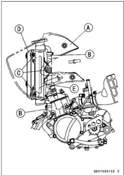
RadiatorInstallation
- Radiatorinstallationisthereverseofremoval.
- Routethewaterandbreatherhosescorrectly.
Torque-RadiatorMountingBolts:8.8N·m(0.90kgf·m,78in·lb)
ShroudMountingBolts:8.8N·m(0.90k gf·m,78
in·lb)
RadiatorInspection
- Checktheradiatorcore.
★ If there are obstruction to airflow, removethem.
★ Ifthecorrugated finsaredeformed, carefully straighten them with the thin blade of ascrewdriverA.
NOTICE
Donotteartheradiatortubeswhilestraightening thefins.
★ If the air passages of the radiator core are blocked more than 20% by unremovable obstructions or irreparably deformed fins, replacetheradiator with anewone.
NOTICE
Whencleaningtheradiatorwithasteamcleaner,be carefulofthefollowingtopreventradiatordamage. Keepthesteamgun[C]awaymorethan0.5m[B] fromtheradiatorcore.Holdthesteamgunperpendicularartothecoresurface.RunthesteamgunfollowingthecorefindirectionA.

natural_image
Close-up of a car radiator grille with a tool inserted, no visible text or symbols
Radiator
CapInspection
- Checktheconditionofthevalvespring[B], andthetop andbottomvalvesealsA oftheradiatorcap.
★Ifanyoneofthemshowsvisibledamage,replacethecap.

- Wetthetopandbottomvalvesealswithwaterorcoolant topreventpressureleaks.
- InstallthecapAonacoolingsystempressuretester[B].
- Watching the pressure gauge, slowly pump the pressure testertobuildup the pressure. The gauge hand must remain within the relief pressurer range in the table below at least 6 seconds. Continuetopump the tester until the relief valve opens, indicated by the gauge hand flicking downward. There relief valve must open within the specified range.
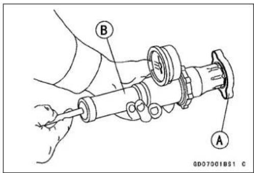
RadiatorCapReliefPressure:
Standard: 108 \~ 137 kPa (1.1 \~ 1.4 kgf/cm², 16 \~ 20 psi)
★ Ifthecapcannotholdthepressure, orifthereliefpressure istoohighortoolow, replacethecapwithanewone.
FillerNeckInspection
- Checktheradiatorfillerneckforsignsofdamage.
- Checktheconditionofthetopandbottomsealingseats Ainthefillerneck. They must besmoothandcleanfor theradiatorcaptofunctionproperly.

natural_image
Technical line drawing of a mechanical component with labeled part A (no text or symbols beyond label)WaterHoses, BreatherHoseInspection
- InaccordancewiththePeriodicMaintenanceChart, visuallyinspectthehosesAforsignsofdeterioration. Squeezethehose.Ahoseshouldnotbehardandbrittle, norshoulditbesoftorswollen.
- Replaceanydamagedhose.

natural_image
Close-up of mechanical components with labeled parts (A), no readable text or symbols presentWaterHoses, Breather Hose Installation
- Installthewaterhosesorbreatherhosebeingcareful tofollowtheperformedbends(seeGeneralInformation chapter). Avoid sharp bending, kinking, flattening, or twisting.
- Tightenthehoseclampssecurely.
EngineTopEnd
TableofContents
Exploded View.... 4-2
Specifications 4-3
Cylinder Head 4-4
CylinderCompressionMeasurement....4-4
Cylinder Head Removal 4-4
Cylinder Head Installation 4-5
Cylinder Head Warp Inspection 4-5
Cylinder 4-6
Cylinder Removal 4-6
Cylinder Installation 4-6
Piston Removal 4-6
Piston Installation 4-7
Cylinder Wear Inspection 4-8
Piston Diameter Measurement 4-8
Piston/CylinderClearanceInspection....4-8
PistonRing, Piston Ring Groove Inspection....4-9
Piston Ring End Gap Inspection 4-9
Piston, PistonPin, ConnectingRodWearInspection....4-10
Muffler (Expansion Chamber) 4-11
Muffler Removal 4-11
Muffler Installation 4-11
Muffler Baffle Replacement.... 4-11

1.SparkPlug
2.CylinderHead
3.Cylinder
4. PistonRing
5."1N"Mark
6."2N"Mark
7. Piston
8."IN"Mark
9.PistonPin
10.ExpansionChamber
11.RubberSeal
12.Gasket
13.MufflerBody(KX65-A1\~A2)
T1:25N·m(2.5kgf·m,18ft·lb)
T2:5.9N·m(0.60kgf·m,52in·lb)
T3:26N·m(2.6kgf·m,19ft·lb)
T4:8.8N·m(0.90kgf·m,78in·lb)
L:Applyanon-permanentlockingagent.
M:Applymolybdenumdisulfidegrease.
O:Apply2-strokeengineoil.
SS:Applysiliconesealant.
Specifications
| ItemStandardServiceLimit | ||
| CylinderHeadCylinderCompression(Usablerange)– –Cylinderheadwarp– – – 0.03mm | –755 ~ 1 177 kPa (7.70 ~ 12.0 kgf/cm2, 109~ 171psi) | |
| Cylinder,PistonCylinderInsideDiameter(15mmbelow fromtheCylinderTopEnd)Piston DiameterPiston/Cylinder ClearancePistonRing/GrooveClearance(Top, Second)PistonRingGrooveWidth(Top, Second)Piston Ring Thickness (Top, Second)Piston Ring End Gap (Top, Second)Piston Pin DiameterPiston Pin Hole DiameterSmallEndInsideDiameter | 44.500~ 44.515mm44.64mm44.453 ~ 44.468 mm0.042 ~ 0.052 mm0.02 ~0.06 mm1.01 ~ 1.03 mm0.97 ~ 0.99 mm0.15 ~ 0.35 mm11.995 ~ 12.000 mm12.001 ~ 12.011 mm16.002~ 16.013mm16.05mm | 44.30 mm–– –0.16 mm1.11 mm0.90 mm0.65 mm11.96 mm12.08 mm |
SpecialTool- PistonPinPullerAssembly:57001-910
CylinderHead
CylinderCompressionMeasurement
- Starttheengine.
- Thoroughlywarmuptheenginesothattheengineoilbetweenthepistonandcylinderwallwillhelpsealcompressionasitdoesduringnormalrunning.
- Stoptheengine.
- Removethefueltank(seeFuelSystemchapter).
- Removethesparkplug, andscrewacompressiongauge firmlyintothesparkplughole.
NOTE
Useacompressiongaugecommerciallyavailable.It's impossibletoinstallastheframewillinterferewiththe operationifusingKAWASAKIspecialtools(PN:57001-221&57001-1159).
- Withthethrottlefullyopen,turntheengineoversharply withthekickstarterseveraltimesuntilthecompression gaugestopsrisingthecompressionisthehighestreading obtainable.
CylinderCompression
UsableRange:
755 \~ 1 177 kPa (7.70 \~ 12.0
- LayastraightedgeAacrossthelowersurfaceofthe headatseveraldifferentpoints,andmeasurewarpby insertingathicknessgauge[B]betweenthestraightedge andthehead.
★Ifwarpexceedstheservicelimit,repairthematingsurface.Replacethecylinderheadifthematingsurfaceis badlydamaged.
CylinderHeadWarp
Standard: 0.03mm

Cylinder
CylinderRemoval
- Drainthecoolant(seeCoolingSystemchapter).
- Remove:
CylinderHead(seethischapter)
Carburetor(seeFuelSystemchapter)
WaterHoseUpperEnd
ClutchCableLowerEnd
MufflerHoldingSprings
- RemovethecylindernutsA.
- Liftoffthecylinder[B], andremovethecylinderbasegasket. If necessary, taplightlyaroundthebaseofthecylinderwithaplasticmallet, takingcarenottodamagethe cylinder.
CylinderInstallation
- Scrapeanycarbonoutoftheexhaustport.
- Checkonacrustofmineralsandrustinthecylinderwater jacket,andremovethemifnecessary.
- Replacethecylinderbasegasketwithanewone.
- Applyengineoiltothepistonsurface, pistonringsand cylinderbore.
- ChecktoseethatthepinAineachpistonringgroove isbetweentheendsofthepistonring,andfitthebaseof thecylinderovereachring,pressinginonoppositesides oftheringasnecessary.Becertainthattheringsdonot slipoutofposition.
- Tightenthecylindernutsdiagonally.
Torque-CylinderNuts:25N·m(2.5kgf·m,18ft·lb)
PistonRemoval
- Removethecylinder.
- Stuffacleanclothintothecrankcaseopeningaroundthe connectingrodsothatnopartswillfallintothecrankcase.
- Removeoneofthepistonpinsnapringswithneedlenose pliers.
- Removethepistonbypushingthepistonpinouttheside fromwhichthesnapringwasremoved.Useapistonpin pullerassemblyA,ifthepinistight.
SpecialTools- PistonPinPullerAssembly:57001-910
- Removethepistonring(s).
○ CarefullyspreadtheringAopeningwithyourthumbs and thenpushupontheoppositesideoftheringtore-moveit.


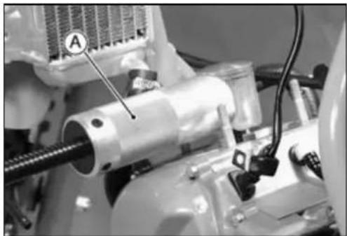
natural_image
Close-up of a mechanical assembly with labeled component A, showing mechanical components and wiring (no readable text or symbols)
Cylinder
PistonInstallation
- Stuffacleanclothintothecrankcaseopeningaroundthe connectingrodsothatnopartswillfallintothecrankcase.
- Scrapeoffanycarbonofthepiston, then lightly polish the pistonwithfineemerycloth.
- Cleancarbonanddirtoutofthepistonringgrooveusing asuitabletool.
NOTICE
Carbonparticlescanbeveryabrasivetopiston ring. Don't allowsuch particlestofallontothe cylinderwalls.
- Wheninstallingthepistonringonthepiston,notethefollowing:
○Firstfitoneendofthepistonringagainstthepinintheringgroove, spreadtheringopeningwiththeotherhand andthensliptheringintothegroove.
○Thetopringhavea“1N”markAonitsuppersurface.
○Thesecondringhavea“2N”mark[B]onitsuppersurface.
○InstalltheringsothatthepinAinthepistonringgroove isbetweentheendsofthepistonring.
- Apply2-strokeengineoiltotheconnectingrodneedle bearingandthepistonpin.
- InstallthepistonAsothatthe"IN"markedside[B]faces theback(intake)sideoftheengine.
- WheninstallingapistonpinsnapringA, compressitonly enoughtoinstallitandnomore.
NOTICE
Donotreusesnaprings,asremovalweakensand deformsthem.Theycouldfalloutandscorethe cylinderwall.
- Fitanewpistonpinsnapringintothesideofthepistonso thattheringopening[B]doesnotcoincidewiththenotch [C]intheedgeofthepistonpinhole.

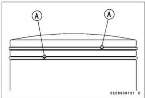


Cylinder
CylinderWearInspection
NOTE
○Measurethecylinderinsidediameterwhenthecylinder iscold(roomorambienttemperature).
- VisuallyInspecttheinsideofthecylinderforscratches andabnormalwear.
★ Ifthecylinderisdamagedorbadlyworn,replaceitwitha newone. - Sincethereisadifferenceincylinderwearindifferentdirections, takeaside-to-sideandafront-tobackmeasurementshowninthefigure.
★ Ifanyofthecylinderinsidediametermeasurementsexceedstheservicelimit, thecylindermustbereplacedwith anewonesincetheELECTROFUSIONcylindercannot beboredorhoned.
CylinderInsideDiameter
Standard: 44.500\~44.515mm, and less than 0.01 mmdifference between any two measurements.
ServiceLimit: 44.64mm,ormorethan0.05 mmdifferencebetweenanytwo measurements.
PistonDiameterMeasurement
- Measuretheoutsidediameter[B]ofthepiston6. 0 mm Aupfromthebottomofthepistonatarightangletothe directionofthepistonpin.
★ Ifthemeasurementisundertheservicelimi t,replace the piston.
PistonDiameter
Standard: 44.453\~44.468mm
ServiceLimit: 44.30mm
Piston/CylinderClearancelnspection
Thepiston-to-cylinderclearanceismeasuredwhenevera pistonorcylinderisreplacedwithanewone. Thestandard piston-to-cylinderclearancemustbeadheredtowhenever thecylinderisreplaced.
Ifonlyapistonisreplaced, the clearancemayexceed the standardslightly. Butitmustnotbelessthantheminimum, inordertoavoidpistonseizure.
Thermostaccuratewaytofindthepistonclearanceis bymakingseparatepistonandcylinderdiametermeasurementsandthencomputingthedifferencebetweenthetwo values.Measurethepistondiameterasjustdescribed,and measurethecylinderdiameterattheverybottomofthe cylinder.
Piston/CylinderClearance
Standard: 0.042\~0.052mm


Cylinder
PistonRing, PistonRing Groove Inspection
- Visually inspect the piston rings and the piston ring grooves.
★Iftheringsarewornunevenlyordamaged,theymustbe replaced.
★Ifthepistonringgroovesarewornunevenlyordamaged, thepistonmustbereplacedandfittedwithnewrings. - Checkforunevengroovewearbyinspectingtheringseating.
- Theringsshouldfitperfectlyparalleltothegroovesurfaces.Ifnot,thepistonmustbereplaced.
- With the piston ring in its groove, makes several measurements with a thickness gauge A to determine piston ring/groove clearance.
★ If the clearance exceed stheservicelimit, measure the thickness of the piston ring
★Iftheringhasworndowntolessthantheservicelimit, replacethering;ifthegroovewidthexceedstheservice limit,replacethepiston.
PistonRing/GrooveClearance(Top, Second)
Standard: 0.02\~0.06mm
ServiceLimit: 0.16mm
PistonRingThickness(Top,Second)
Standard: 0.97\~0.99mm
ServiceLimit: 0.90mm
PistonRingGrooveWidth(Top,Second)
Standard: 1.01\~1.03mm
ServiceLimit: 1.11mm
PistonRingEndGapInspection
- PlacethepistonringAinsidethecylinder[B], using the pistontolocatetheringsquarelyinplace.
- Setitclosetothebottomofthecylinder, wherecylinder wearislow.
- Measurethegap[C]betweentheendsoftheringwitha thicknessgauge.
★Ifthegapiswiderthantheservicelimit,theringisover-wornandmustbereplaced.
PistonRingEndGap(Top, Second)
Standard: 0.15\~0.35mm
ServiceLimit: 0.65mm
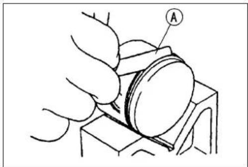

Cylinder
Piston, PistonPin, ConnectingRodWear Inspection
- VisuallyinspectthesnapringAstillfittedinplace.
★ Iftheringshowsweaknessordeformation, replacethering. Also if the pinhole grooveshowsexcessive wear, replacethepiston. - Measurethediameterefthepistonpin[B]withamicrometer.
★ Ifthepistonpindiameterislessthantheservicelimitat anypoint, replacethepistonpin. - Usingacylindergauge, measurethediameterofbothof pistonpinholes[C]inthepistonandtheinsidediameter oftheconnectingrodsmallend.
★ Ifeitherpistonpinholediameterexceedstheservicelimit, replacethepiston.
★ If the connecting rod small ends in diameter exceeds the servicelimit, replacethe crankshaft assembly. - Checktheneedlebearing[D].
○ Therollersinaneedlebearingnormallywearverylittle, andwearisdifficulttomeasure.Insteadofmeasuring, inspectthebearingforabrasion,colorchange,otherdamage.
★ Ifthereisanydoubtastotheconditionofaneedlebearing,replacethebearingandpistonpin.
PistonPinDiameter
Standard: 11.995\~12.000mm
ServiceLimit: 11.96mm
PistonPinHoleDiameter
Standard: 12.001\~12.011mm
ServiceLimit: 12.08mm
SmallEndInsideDiameter
Standard: 16.002\~16.013mm
ServiceLimit: 16.05mm

Muffler(ExpansionChamber)
MufflerRemoval
- Remove:
RightShroud
RightSideCover
- Removethemufflermountingbolts[B]andpullthemufflerAofftowardtherear.
- RemovethespringsAholdingtheexhaustpipeholding
- Removetheexpansionchamberdampermountingbolts A, and pullofftheexpansionchambertotheforward.
- Removetheexhaustgasket.
MufflerInstallation
- Scrapeanycarbonoutoftheexpansionchamber.
- ChecktheexhaustO-ringsforsignsofdamage.
★Ifnecessary, replacethemwithnewones.
- InstallthespringsAholdingtheexhaustpipesothattheir fixedhooks[B]facethecylinder.
Torque-MufflerMountingBolts:8.8N·m(0.90kgf·m,78in·lb)
ExpansionChamberDamperMountingBolt, Nut: 8.8 N·m (0.90 kg f·m, 78 in·lb)
MufflerBaffleReplacement
Replacethemufflerbaffleifexhaustnoisebecomestoo loudortheengineperformedrops.
- RemovethemufflerpipeboltsA, and pull themuffler pipe[B] from themufflerbody.
- Removethemuffler.

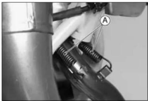
natural_image
Close-up of mechanical components with springs and a labeled section (A), no readable text or symbols present.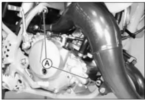
natural_image
Close-up of a mechanical assembly with labeled component A (no readable text or symbols beyond label)

4-12ENGINETOPEND
Muffler(ExpansionChamber)
- UnscrewtheinnerpipemountingboltsA.
-
Pulltheinnerpipe[B]fromthemufflerbody.
-
Pullofftheoldmufflerbaffle, and install thenewmuffler baffleAintothemufflerbody.
- Applysiliconesealanttothecircumference[B]oftheinner pipe.
- Applyanon-permanentlockingagenttotheinnerpipe mountingbolts.
• Installthemuffler.
Torque-InnerPipeMountingBolts:5.9N·m(0.6kgf·m,52in·lb)


EngineRightSide
TableofContents
Exploded View.... 5-2
Specifications 5-4
Clutch Cable 5-5
Clutch Lever Free Play Inspection 5-5
Free Play Adjustment.... 5-5
Clutch Cable Removal 5-6
Clutch Cable Installation 5-6
ClutchCableLubricationandInspection......5-6
Right Engine Cover 5-7
Right Engine Cover Removal 5-7
Engine Right Cover Installation.... 5-7
RightEngineCoverDisassembly 5-9
Right Engine Cover Assembly 5-9
Clutch 5-10
Clutch Removal 5-10
Clutch Installation.... 5-10
Friction and Steel Plates Wear, Damage Inspection.... 5-11
Friction and Steel Plate Warp Inspection 5-11
SpringFreeLengthMeasurement....5-12
FrictionPlate/ClutchHousingClearanceInspection....5-12
Clutch Hub Spline Inspection.... 5-12
External Shift Mechanism.... 5-13
External Shift Mechanism Removal 5-13
External Shift Mechanism Installation 5-13
External Shift Mechanism Inspection.... 5-13
Primary Gear 5-14
Primary Gear Removal 5-14
Primary Gear Installation 5-14
Primary Gear Removal (KX65A6F \~) 5-14
Primary Gear Installation (KX65A6F \~) 5-14
Kickstarter 5-16
Kickshaft Removal 5-16
Kickshaft Installation 5-16
Kickstarter Assembly Disassembly/Assembly 5-16
Idle Gear Removal 5-16
Idle Gear Installation 5-16

ExplodedView
- ClutchLever
- ClutchCable
- Release Lever Shaft
- ClutchPusher
5.Shim(s)
6.SpringPlatePusher - ClutchHub
- ClutchWheel
-
FrictionPlate
-
SteelPlate
-
ClutchHousing
12.Sleeve
13.PrimaryGear
14.GearSetLevers
15.ShiftShaft
16.KickstarterIdleGear
17.RatchetGear
18.KickGear
19.KickShaft
20.KX65-A1\~A6
T1:8.8N·m(0.90kgf·m,78in·lb)
T2:64N·m(6.5kgf·m,47ft·lb)
T3:9.3N·m(0.95kgf·m,82in·lb)
T4:5.2N·m(0.53kgf·m,46in·lb)
T5:1.5N·m(0.15kgf·m,13in·lb)
T6:49N·m(5.0kgf·m,36ft·lb)
T7:12N·m(1.2kgf·m,104in·lb)
EO:ApplyEngineoil.
G: Apply hight temperature grease.
Lh:Left-handThreads
M:Applymolybdenumdisulfidegrease.
O:Applyoil.
Specifications
| Item | StandardServiceLimit | |
| Clutch | ||
| Lever Free Play | 8 ~ 13 mm | --- |
| FrictionPlateThickness3.1~ 3.3mm2.9mm | ||
| Steel Plate Thickness | 1.47 ~ 1.73 mm | 1.37 mm |
| FrictionPlateWarpNotmorethan0.2mm0.3mm | ||
| SteelPlateWarp | Notmorethan0.15mm0.3mm | |
| ClutchSpringFreeLength28.1mm26.7mm | ||
| Friction Plate/Clutch Housing Clearance | 0.3 ~ 0.6 mm | 0.9 mm |
Special Tools - Flywheel & Pulley Holder: 57001-1605
OutsideCirclipPliers: 57001-144
ClutchCable
Duetofrictionplatewearandclutchcablestretchchover alongperiodofuse,theclutchmustbeadjustedinaccordancewiththePeriodicMaintenanceChart.
WARNING
Theengineandexhaustsystemgetextremelyhot duringnormaloperationandcancauseserious burns.Nevertouchtheengineorexhaustpipe duringclutchadjustment.
ClutchLeverFreePlayInspection
- SlidetheclutchleverdustcoverAoutofplace.
- Check that the clutch cable upper end is fully seated in the adjuster[B].
- Check that the clutch lever [C] has 8 \~ 13 mm of play [D].
★ Ifitdoesnot,adjusttheleverplay.
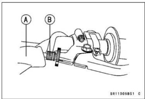

FreePlayAdjustment
- Slidetheclutchleverdustcoveroutofplace.
- LoosentheknurledlocknutA.
- Turntheadjuster[B]sothattheclutchleverwillhave8\~13mmofplay.
NOTE
Besurethattheoutercableendattheclutchleveris fullyseatedintheadjusterattheclutchlever,oritcould slipintotheplacelater,creatingenoughcableplayto preventclutchdisengagement.
- Tightenthelocknut .
- Ifitcannotbedone,loosentheadjustingnutsAatthe bottomoftheclutchcable,andturnthenutssothatclutch leverhas8\~ 13mmofplay.
- After the adjustment is made, tighten the locknut, and starttheengineandcheckthattheclutchdoesnotslip andthatitreleaseproperly.


natural_image
Close-up of mechanical components with no visible text or symbolsClutchCable
ClutchCableRemoval
- Slidethedustcoveroutofplace.
- Loosentheadjustingnutsatthelowerofthecable, and turntheadjustingnutstogivethecableplentyofplay.
- LoosentheknurledlocknutAattheclutchlever, and screwintheadjuster[B].
- Lineuptheslots[C]intheclutchlever,knurledlocknut, andadjuster,andthenfreethecablefromtheclutchlever.
- Freetheclutchinnercabletipfromtheclutchrelease lever.
NOTICE
Donotremovetheclutchreleaseshaftunlessitis absolutelynecessary.Ifremoved,releaseshaftoil sealmustbereplacedwithanewone.
- Pulltheclutchcableoutoftheframe.
ClutchCableInstallation
- RuntheclutchcableaccordingtotheCable, Wire and HoseRoutingsectionoftheGeneralInformationchapter.
- Adjusttheclutchcable(seeFreePlayAdjustment).
ClutchCableLubricationandInspection
- LubricatetheclutchcableAusingthepressurecable lubberinaccordan cewiththePeriodicMaintenance Chart.
- Withthecabledisconnectedatbothends, thecable shouldmovef reelywithinthecablehousing(seeAppendixchapter).


natural_image
Line drawing of hands holding a syringe with a labeled component (A), no text or symbols presentRightEngineCover
RightEngineCoverRemoval
- Draintheengineoil(seeEngineOilChangeintheEngine BottomEnd/Transmissionchapter).
- Drainthecoolant(seeCoolantDrainingintheCooling Systemchapter).
- Remove:
WaterHoseLowerEnds
KickPedal
ClutchCableLowerEnd(seethischapter)
BrakePedal
WaterPumpImpeller(seeCoolingSystemchapter)
- Removetherightenginecovermountingbolts.
- TurntheclutchreleaseleverAtowardtherearandremovetherightenginecover[B].
EngineRightCoverInstallation
- ApplymolybdenumdisulfidegreaseAtothewaterpump shafttopreventwaterpumpsealdamage.
NOTICE
Iftherightenginecoverisinstalledwithoutgreasingthepumpshaft, the pumpsealcoulddamage.
- TherearetwoknockpinsAonthematingsurfacesof thecrankcaseandrightenginecover.
- Runthebreatherhose[B]intotheclamp[C]andposition itwiththerightenginecovermountingboltasshown.

natural_image
Close-up mechanical assembly showing a central circular component with labeled parts A and B (no readable text or symbols)
natural_image
Mechanical gear assembly showing interlocking gears and a central shaft (no text or symbols visible)
RightEngineCover
- WhenthereleaseleverAisturnedtotheright[B]lightly, choosetheamountofshims[C]ontheclutchpusher[D] sothattheincludedanglebetweenthereleaseleverA andtheline[E]attherightangletotherightenginecover isapprox.24°F.

- Stickthenewrightenginecovergasketinpositionwitha thinlayerofgrease.
- Applyahighttemperaturegreasekickshaftoilseallips andkickshaftspline.
- Torquetherightenginecoverboltsandkickshaftmountingbolt.
Torque-RightEngineCoverBolts:8.8N·m(0.90kgf·m,78in·lb)
KickPedalBolt:12N·m(1.2kgf ·m,89in·lb)
- Runtheclutchcableandthecoolinghosesaccordingto theCable, Wire, and HoseRoutingsectionintheGeneral Informationchapter.
- Adjusttheclutchcable(seethischapter).
- Checktheclutchreleaseleverangle.
- Fillthecrankcasewithengineoil(seeEngineBottom End/Transmissionchapter).
- Filltheenginewithcoolant(seeCoolingSystemchapter).
NOTICE
Donotremovetheclutchreleaseshaftunlessitis absolutelynecessary.Ifremoved,youmustreplace theoilsealwithanewone.
- Refertothecoolingsystemchapterforwaterpumpseal andwaterpumpbearingremoval.
RightEngineCover
RightEngineCoverDisassembly
- Removetherightenginecover(seethischapter).
- PullouttheclutchreleaseshaftA.
NOTICE
Donotremovetheclutchreleaseshaftunlessitis absolutelynecessary.Ifremoved,youmustreplace theoilsealwithanewones.
- Refertothecoolingsystemchapterforwaterpumpseal andwaterpumpbearingremoval.

natural_image
Close-up of a mechanical component with a central shaft and circular features, labeled 'A' (no readable text or symbols beyond label)RightEngineCoverAssembly
- Whentheoillevelgauge, needlebearingsandoilseal wereeremoved, notethefollowing.
○SetthenewoillevelgaugeAsothatitsmetalportion[B]facesoutwardandpressinthegaugeuntilitisbottomed.
○Pressthenewlowerneedlebearing[C]untilitisbottomed.Asfortheinstallationdirection,bothsidesare available.
○Setthenewupperneedlebearing[D]withthemarked sidefacingoutandpressbearinguntilitisbottomed.
○Pressthenewoilseals[E]untiltheyarebottomedand applyalittlehightemperaturegrease[F]ontherips.

- RefertotheCoolingSystemchapterforwaterpumpseal andwaterpumpbearinginstallation.
5-10ENGINERIGHTSIDE
Clutch
ClutchRemoval
- Removetherightenginecover(seeRightEngineCoverRemoval).
-
Removethemagnetocover.
- Holdthemagnetoflywheelsteadywithflywheel&pulley holderA.
SpecialTool-Flywheel&PulleyHolder:57001-1605
- Remove:
ClutchHubNutA
ClutchSpringBolts[B]
ClutchSpringHolder[C]
ClutchHub[D]
- Remove:
FrictionPlatesandSteelPlates
ClutchWheel
ClutchHousing
SleeveandWashers
ClutchInstallation
- Applymolybdenumdisulfidegreasetotheoutsideofthe sleeveandclutchhousingbearinghole.
- Install:
ThrustWashersA
Sleeve[B]
ClutchHousing[C]
ClutchWheel[D]
FrictionPlatesandSteelPlates[E]
ClutchHub[F]

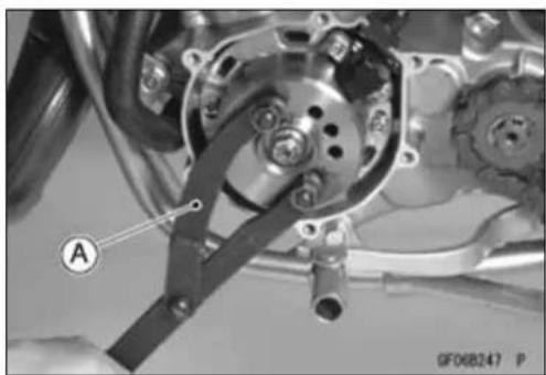
natural_image
Mechanical assembly diagram showing a cam mechanism with labeled component A (no readable text or symbols)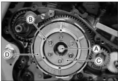

Clutch
NOTICE
Ifdrysteelplatesandfrictionplatesareinstalled, applytransmissionoiltothesurfacesofeachplate toavoidclutchplateseizure.
○Installthefrictionplatesandsteelplates,startingwitha frictionplateandalternatingthem,finishingwithafriction plate.
○Installthehubnutandclutchspringbolts.
Torque-ClutchHubBolt:64N·m(6.5kgf·m,47ft·lb) ClutchSpringBolts:9.3N·m(0.95kgf·m,82in·lb)
- Applymolybdenumdisulfidegreasetotheclutchspring platepusher.
- Install: ClutchSpringPlatePusher Shim(asrequired) ClutchPusher MagnetoCover EngineRightSideCover
FrictionandSteelPlatesWear, DamageInspection
- Visually inspect the friction and steel plate to see if they show an sign of seizure, or uneven wear.
★Ifanyplatesshowsignsofdamage,replacethefriction platesandsteelplatesasaset. - MeasurethethicknessAofthefrictionplates[B]and steelplateswithverniercalipers.
★Iftheyhavewornpasttheservicelimit,replace themwith newones.
FrictionPlateThickness
Standard: 3.1\~3.3mm
ServiceLimit: 2.9mm
SteelPlateThickness
Standard: 1.47\~1.73mm
ServiceLimit: 1.37mm
FrictionandSteelPlateWarpInspection
- Placeeachfrictionplateorsteelplateonasurfaceplate, andmeasurethegapbetweenthesurfaceplateAand eachfrictionplateorsteelplate[B]withathicknessgauge [C]Thegapistheamountoffrictionorsteelplatewarp.
★Ifanyplateiswarpedovertheservicelimit,replaceitwith anewone.
FrictionandSteelPlatesWarp
Standard:
FrictionPlateNotmorethan0.2mm
SteelPlate Not more than 0.15 mm
ServiceLimit:
FrictionPlate0.3mm
SteelPlate0.3mm
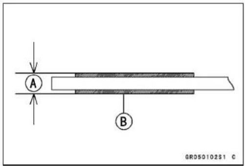

Clutch
SpringFreeLengthMeasurement
- SincethespringAbecomesshorterasitweakens, checkitsfreelengthtodetermineitscondition.
★ Ifanyofthespringsisshorterthantheservicelimit, it must bereplaced.
ClutchSpringFreeLength
Standard: 28.1mm
ServiceLimit: 26.7mm
FrictionPlate/ClutchHousingClearance Inspection
- Measure the clearance between the tongues A on the friction plate and the fingers [B] of the clutch housing.
★ If this clearance is excessive, the clutch will be noisy.
★ Iftheclearanceexceedstheservicelimit,replacethefrictionplates.
FrictionPlate/ClutchHousingClearance
Standard: 0.3\~0.6mm
ServiceLimit: 0.9mm
ClutchHubSplineInspection
- Visuallyinspectwheretheteethonthesteelplateswear againstthesplinesAofthe clutchhub.
★ Iftherearenotcheswornintothesplines,replace the clutchhub.Also,replacetheclutchplatesiftheirteeth aredamaged.

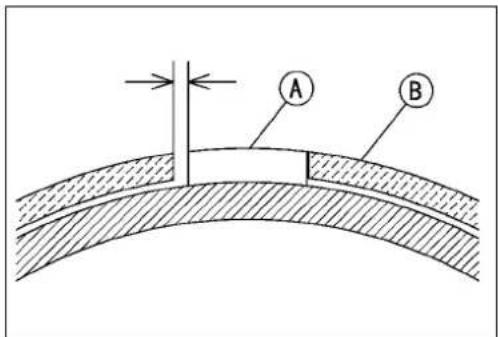

natural_image
Technical line drawing of a mechanical gear assembly with labeled point A (no text or symbols beyond label)ExternalShiftMechanism
ExternalShiftMechanismRemoval
- Remove:
ShiftPedal
RightEngineCover
ClutchHousing
- RemovetheenginemountingboltsAtopullouttheexternalshiftmechanism.
- PullouttheexternalshiftmechanismA, liftingtheengine [B].
- Removethegearsetleverspring[C].
- Removetheleversetscrew[D]andtakeoffthesetlevers [D][E].

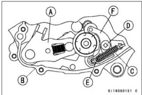
ExternalShiftMechanismInstallation
- InstallthereturnspringAsothatthelargeroundedge sidefacesin.
- Beforeinstallingtheshiftshaft,applyhightemperature greasetotheoilseallipsandshiftshaftsplines.
- Tightenthegearsetleverscrew.
Torque-GearSetLeverScrew:8.8N·m(0.90kgf·m,78in·lb)
ShiftPedalBolt:8.8N·m(0.90kgf·m,78in·lb)

natural_image
Close-up mechanical component with labeled point A, showing gears and shafts (no readable text or symbols)
ExternalShiftMechanismInspection
- ChecktheshiftshaftAforbendingordamagetothe splines.
★Iftheshaftisbent, straightenorreplaceit. Ifthesplines aredamaged, replacetheexternalshiftmechanism. - Checkthereturnspring[B]andarmspring[C]forcracks ordistortion.
★ Ifthespringsaredamagedinanyway, replacethem. - Checktheshiftmechanismarm[D]fordistortion.
★Iftheshiftmechanismarmisdamagedinanyway,re-placetheshiftmechanism. - Checkthegearsetlevers, and it's spring for cracks or distortion.
★ Iftheleverorspringisdamagedinanyway, replacethem.
5-14ENGINERIGHTSIDE
PrimaryGear
PrimaryGearRemoval
- Removetherightenginecover(seeRightEngineCoverRemoval)
- RemovetheirclipA, and takeoff the primary gear[B] and waterpump drive gear.
SpecialTools-OutsideCirclipPliers:57001-144
PrimaryGearInstallation
- PutthewaterpumpdrivegearAandprimarygear[B]on thecrankshaft[C].Forthebothgears,installationeither obverseorreversesideisavailable.

natural_image
Mechanical gear assembly diagram showing teeth and gears (no text or symbols)
PrimaryGearRemoval(KX65A6F \~)
- Removetherightenginecover(seeRightEngineCoverRemoval).
- Removethemagnetocover.
- RemovetheprimarygearnutA, washer, and the primary gear[B].
○Primarygearnutisleft-handthreads.
NOTE
○Usetheflywheel&p ulleyholdertopreventthecrank-shaftfromtherotating.
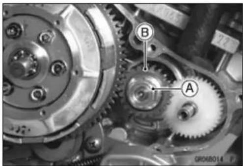
SpecialTools-Flywheel&PulleyHolder:57001-1605
PrimaryGearInstallation(KX65A6F \~)
- InserttheprimarygearAtothecrankshaftthenhollow sidefacingtotheoutside.
- Install: SpringWasher[B] PrimaryGearNut[C]

PrimaryGear
- InstallthespringwasherAwiththeconcavesidefacing totheinward.
- Temporarilytightentheprimarygearnut[B].

- Tightentheprimarygearnut
○Primarygearnutisleft-handthreads.
Torque-PrimaryGearNut:49N·m(5.0kgf·m,36ft·lb)
SpecialTools-Flywheel&PulleyHolder:57001-1605
NOTE
○ Usetheflywheel&pulleyholdertopreventthecrank-shaftfromtherotating.
- Install:
RightEngineCover(seeRightEngineCover)
MagnetoCover
5-16ENGINERIGHTSIDE
Kickstarter
KickshaftRemoval
- Remove:
RightEngineCover(seeRightEngineCoverRemoval) ClutchHousing - PulltheendofthekickspringAoutoftheholeinthe crankcase.
- Removetheratchetguidebolt[B]andratchetguidescrew [C],takeofftheratchetguide[D].
- Removethekickstarterassembly[E].
KickshaftInstallation
- Torquetheratchetguideboltandscrew. Torque-RatchetGuideBolts:8.8N·m(0.90kgf·m,78in·lb) RatchetGuideScrew:5.2N·m(0.53kgf·m,46 in·lb)
KickstarterAssemblyDisassembly/Assembly
- Thekickstarterassemblyconsistsofthefollowingparts. - Checkthekickstarterassemblypartsfordamage.Any damagedpartsshouldbereplacedwithne wones.
A.IdleGear
B.Circlip
C.Washer
D.Spring
E.RatchetGear
F.KickGear
G.KickShaft
H.KickSpring
I.SpringGuide
- Applymol ybdenumdisulfidegreasetotheinsideofthe kickgearandratchetgear.
- WhenassemblingtheratchetgearAontothekickshaft [B], a lignthenotch[C]ontheratchetgearwiththehole [D]onthekickshaft.
- Replacethecirclipsthatwereremovedwithnewones.
SpecialTool- OutsideCirclipPliers:57001-144
IdleGearRemoval
- Remove:
RightEngineCover(seeRightEngineCoverRemoval) ClutchHousing(seeClutchRemoval) - RemovethecirclipAandpullofftheidlegear[B].
SpecialTool- OutsideCirclipPliers:57001-144
IdleGearInstallation
- Applymolybdenumdisulfidegreasetotheinsideofthe idlegear.
- Replacethecirclipwithanewone.
SpecialTool- OutsideCirclipPliers:57001-144


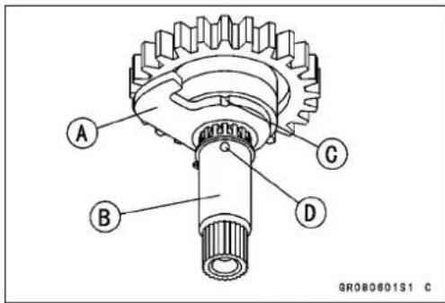

natural_image
Mechanical gear assembly with labeled components (A, B, C) and no visible text or symbolsEngineRemoval/Installation
TableofContents
Exploded View.... 6-2
Engine Removal/Installation 6-3
Engine Removal.... 6-3
Engine Installation.... 6-4
ExplodedView

1.Frame
2.PivotShaft
3.Swingarm
T1:25N·m(2.5kgf·m,18ft·lb)
29N·m(3.0kgf·m,21ft·lb):KX65-A3\~
T2:69N·m(7.0kgf·m,51ft·lb)
G:Applygrease.
L: Applyanon-permanentlockingagent.
GH020501W4 C
EngineRemoval/Installation
EngineRemoval
- Draintheengineoil(seeEngineBottomEnd/Transmissionchapter).
- Drainthecoolant(seeCoolingSystemchapter).
- Remove:
RadiatorShrouds
SideCovers
Seat
FuelTank
WaterHoses
Radiators
ExpansionChamber
SparkPlug
Carburetor(withCablesandHoses)
ClutchCableLowerEnd
DriveChain
EngineSprocket
ShiftPedal
BrakePedal
- Disconnectthemagnetooutputlead, andfreetheleads fromtheclamp.
- PlaceajackAundertheframetoliftthemotorcycleoff theground,andputblocksunderthefrontandreartires tosteadythemotorcycle.

WARNING
Sincetheswingarmpivotshaftalsoservesasthe enginemountingbolt,removingitmaycausethe motorcycletofalloverandcauseinjury.When removingtheswingarmpivotshaft,besurethe frameiswellsupportedsothemotorcyclewillnot fallwhenthepivotisremoved.

natural_image
Mechanical assembly diagram showing labeled components A, B, and C (no text or symbols beyond labels)SpecialTool-Jack:57001-1238
- Removetheenginemountingbolts[B].
- Pullouttheswingarmpivotshaft[C].
- Lifttheengineouttotheright.
EngineRemoval/Installation
EngineInstallation
• Installtheengineontheframe.
- Before tightening the engine mounting nuts, measure the left and right clearance A between the bosses [B] of crankcase and frame brackets [C] with thickness gauge.
Clearance: Under0.3mm
★ Iftheclearancesareoverthespecifiedvalue,adjustthem byinsertingtheshim(PartNo. 92180-1354)andtighten thefollowingnuts.
Torque-EngineMountingNuts:
25N·m(2.5kgf·m,18ft·lb) 29N·m(3.0kgf·m,21ft·lb):KX65-A3\~ SwingArmPivotShaftNut:69N·m(7.0kgf·m,51 ft·lb) Shift Pedal Bolt: 8.8 N·m (0.90 kgf·m, 78 in·lb)
- Toroutetheleads, cablesandhoses, refertotheGeneral Informationchapter.
- Toinstallpartsremoved, refertotheappropriatechapters.
- Fillthecoolingsystemwithcoolant(seeCoolingSystem chapter).
- Filltheenginewithengineoil(seeEngineBottom End/Transmissionchapter).
- Adjust: ThrottleCable ClutchCable DriveCha in RearBrake
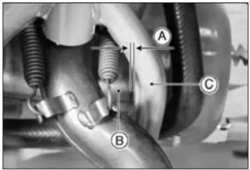
EngineBottomEnd/Transmission
TableofContents
Exploded View.... 7-2
Specifications 7-4
Transmission Oil 7-5
Oil Level Inspection.... 7-5
Oil Change 7-5
Crankcase 7-7
Crankcase Splitting 7-7
Crankcase Disassembly 7-8
Crankcase Assembly 7-8
Crankshaft, Connecting Rod 7-10
Crankshaft Removal 7-10
Crankshaft Installation 7-10
Crankshaft Disassembly 7-10
Crankshaft Assembly 7-10
Connecting Rod Big End Radial Clearance Inspection.... 7-11
Connecting Rod Big End Seizure Inspection 7-11
Connecting Rod Big End Side Clearance Inspection.... 7-11
Crankshaft Runout Inspection.... 7-11
Crankshaft Alignment Inspection 7-12
Transmission 7-13
Shaft Removal 7-13
Shaft Installation 7-13
Shaft Disassembly 7-13
Shaft Assembly 7-13
Shift Drum and Fork Installation.... 7-14
Shift Fork Bending Inspection 7-15
ShiftFork/GearGrooveWearInspection....7-15
ShiftForkGuidePin/ShiftDrumGrooveWearInspection....7-15
Gear Damage Inspection.... 7-16
GearDog/GearDogHoleDamageInspection....7-16
Ball Bearing Wear Inspection.... 7-16
7-2 ENGINEBOTTOMEND/TRANSMISSION
ExplodedView

ExplodedView
- CrankshaftAssembly
2.MagnetoStator
3.MagnetoFlywheel
4.LeftCrankcase
5.RightCrankcase
6.DriveShaft - OutputShaft
- EngineSprocket
9.ShiftRod
10.ShiftFork - OperatingPlate
12.ShiftDrum
13.ShiftShaft
14.ShiftPedal
15.KX65-A1\~A5
16.KX65-A1\~A6
T1:20N·m(2.0kgf·m,15ft·lb)
T2:29N·m(3.0kgf·m,21ft·lb)
T3:8.8N·m(0.90kgf·m,78in·lb)
T4:8.8N·m(0.90kgf·m,78in·lb)
T5:24N·m(2.4kgf·m,17ft·lb)
T6:8.8N·m(0.90kgf·m,78in·lb)
T7:5.2N·m(0.53kgf·m,46in·lb)
EO:Applyengineoiltothetransmissiongearsandshiftforks,etc.
G: Apply hightemperaturegrease.
L: Applyanon-permanentlockingagent.
LG:Applyliquidgaskettotheleftandrightcasematingsurface.
M:Applymolybdenumdisulfidegrease.
O:Apply2-strokeengineoil.
R: Replacementparts
Specifications
| Item | StandardServiceLimit | |
| TransmissionOil:EngineOil:GradeViscositySAE10W-40-- Capacity0.5L-- | APISG,SH,SJ,SLorSMwithJASOMA,MA1orMA2 | --- |
| Crankshaft,ConnectingRodConnectingRodBendNotmorethan0.05mm/100mm0.2mm/100mmConnectingRodTwistNotmorethan0.05mm/100mm0.2mm/100mmConnectingRodBigEndRadial ClearanceConnectingRodBigEndSide ClearanceCrankshaftRunout | 0.025~ 0.037mm0.09mm0.35~ 0.45mm0.65mmNotmorethan0.03mm | 0.05mm |
| TransmissionShift Fork Ear ThicknessGear Shift Fork Groove WidthShift Fork Guide Pin DiameterShiftDrumGrooveWidth | 3.90 ~ 4.00 mm4.05 ~ 4.15 mm5.90 ~ 6.00 mm6.05~ 6.20mm6.25mm | 3.80 mm4.25 mm5.80 mm |
Special Tools - Bearing Puller Adapter: 57001-136
OutsideCirclipPliers: 57001-144
BearingPuller: 57001-158
BearingDriverSet:57001-1129
CrankcaseSplittingToolAssembly:57001-1362
CrankshaftJig: 57001-1439
Sealant - LiquidGasket, TB1105B:92104-002
TransmissionOil
Inorderforthetransmissionandclutchtofunctionproperly,alwaysmaintainthetransmissionoilattheproperlevel andchangetheoilperiodically.

WARNING
Vehicleoperationwithinsufficient,deteriorated,or contaminatedtransmissionoilwillcauseacceleratedwearandmayresultinengineortransmission seizure,accident,andinjury.Checktheoillevelbeforeeachuseandchangetheoilandfilteraccordingtotheperiodicmaintenancechart.
OilLevelInspection
- Situatethemotorcyclesothatitisperpendiculartothe ground.
- Ifthemotorcyclehasjustbeenused, waitseveralminutes untiltheoilsettles.
- Checkthattheoillevelcomesupbetweentheupperlevel Aandlowerlevel[B]throughtheoillevelgauge[C]ontherightenginecover.
★ If the oil level to high, removal the excess oil through the oil filler opening using asyringe or some others suitable device.
★Iftheoillevelistoolow,addthecorrectamountofoil. Usethesametypeandmakeofoilthatisalreadyinthe engine.
NOTE
○ Iftheengineoiltypeandmakeareunknown,useany brandofthespecifiedoiltotopupthelevelinpreference torunningtheenginewiththeoillevellow. Thenatyour earliestconvenience,changetheoilcompletely.
OilChange
- Warmuptheenginethoroughlysothattheoilwillpickup anysedimentanddraineasily. Thenstoptheengine.
- Placeanoilpanbeneaththeengine
- RemovetheengineoidrainplugAonthebottomofthe engine, andlettheoidraincompletely.
NOTE
○ Holdthemotorcycleuprightsothattheoilmaydrain completely.


TransmissionOil
- Checkthegasketattheengineoildrainplugfordamage.
★Replacethegasketwithanewoneifitisdamaged. - Aftertheoilhascompletelydrainedout,installtheengine oildrainplugwiththegasket,andtightenit.
Torque-EngineOilDrainPlug:20N·m(2.0kgf·m,15ft·lb)
- Filltheenginewithagoodqualityengineoilspecifiedbelow.
- Checktheoillevel.
RecommendedEngineOil
Grade: APISG, SH, SJ, SL or SM with JASOMA, MA1 or MA2
Viscosity: SAE10W-40
EngineOilCapacity
Capacity: 0.5L
NOTE
○Donotaddanychemicaladditivetotheoil. Oilsfulfilling theaboverequirementsarefullyformulatedandprovide adequatelylubricationforboththeengineandtheclutch.
Although 10W-40engineoilistherecommendedoilfor most conditions, the oil viscosity may need to be changed to accommodate atmospheric conditions in your riding area.

Crankcase
CrankcaseSplitting
- Removetheengine(seetheEngineRemoval/Installation chapter).
- Settheengineonacleansurfacewhilepartsarebeing removed.
- Remove:
MagnetoCover
OutputShaftSleeveAandO-ring[B]

CylinderHead(seeEngineTopEndChapter)
Cylinder(seeEngineTopEndChapter)
Piston(seeEngineTopEndChapter)
RightEngineCover(seeEngineRightSideChapter)
Clutch(seeEngineRightSideChapter)
PrimaryGear(seeEngineRightSideChapter)
KickstarterAssembly(seeEngineRightSideChapter)
KickstarterIdleGear(seeEngineRightSideChapter)
GearSetandNeutralSetLeversA
MagnetoFlywheelandStator(seeElectricalSystem
Chapter)

- RemovethecrankcaseboltsA.

natural_image
Close-up of a mechanical component with labeled parts (A), showing internal gears and mounting holes (no readable text or symbols)- InstallthecrankcasesplittingtoolAandadapter[B]into theleftsideofthecrankcase.Becertaintoscrewthetool inalltheway.
SpecialTools-CrankcaseSplittingToolAssembly:57001-1362
BearingPullerAdapter:57001-136
- Tightentheboltonthecrankcasesplittingtooltosplitthe crankcasehalves.
- Oncethecrankcaseissplit,removethecrankcasesplittingtool,andliftofftheleftcrankcasehalf.
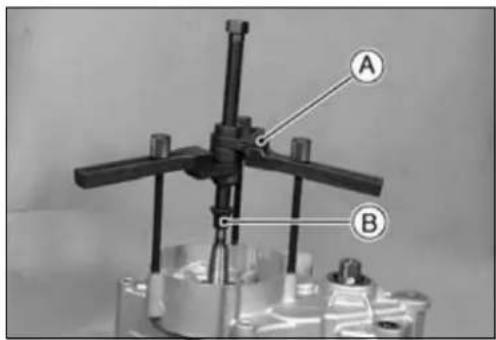
Crankcase
- PullouttheshiftrodsA.
- Disengagetheshiftforkguidepinsfromtheshiftdrum grooves.
- Takeofftheshiftdrum[B]
- Removetheshiftforks[C]fromthetransmissiongears.
- Takeoutthedriveshaft[D]andoutputshaft[E]together withtheirgearmeshed.
- Removethecrankshaftfromtherightcrankcasehalfusingapress.

CrankcaseDisassembly
NOTICE
Donotremovethebearingsandtheoilsealsunless itisnecessary. Removalmaydamagethem.
CrankcaseAssembly
- Beforefittingtheleftcaseontherightcase,notethefollowing:
○ Chipofftheoldgasketfromthematingsurfacesofthe crankcasehalves, andcleanoffthecrankcasewithahigh flash-pointsolvent. Aftercleaning, applytransmissionoil tothetransmissiongears, shiftdrum, shiftforksandso on.
Besuretoreplaceanyoilsealremovedwithanewone. Pressinthenewoilsealusingapressandsuitabletools sothatthesealsurfaceisflushwiththesurfaceofthe crankcase.
○AsforthecrankshaftoilsealA,ontherightcrankcase half[B]pressinthesealuntilitisbottomed.
○Applyhightemperaturegreasetotheoilseallips.
○Pressintheballbearingsusingthebearingdriversetuntil thebearingisbottomed.
SpecialTool-BearingDriverSet:57001-1129
○ Tightenthedriveshaftbearingretainingscrewssecurely. Torque-BearingRetainingScrews:8.8N·m(0.90kgf·m,78 in·lb)
○ Ifthecrankshaftbearingsstayonthecrankshaftwhen splittingthecrankcase,removethebearingsfromthe crankshaftandreinstalltheminthecrankcase,andthen assemblethecrankcase(seeCrankshaftRemovaland Installation).

Crankcase
- TurnthecrankshaftAtoBDC[B], and install the crankshaft jig[C] between the fly wheels opposite the connecting rodbig end to protect fly wheel alignment as shown. Install the suitable shaft[D] to there are end of the crankshaft jig.
Ofthecrankshafthasbeenremovedfromthecrankcase, installthejigbetweenthecrankshaftflywheelsbefore pressingthecrankshaftintotherightcrankcasehalf.
SpecialTool-CrankshaftJig:57001-1439
• Installthetransmissionshaftasaset(seethischapter).
- Installtheshiftfork, shiftdrumandshiftrod.
- Checktoseethatthecrankcaseknockpinsareinplace ontherightcrankcasehalf.Ifanyofthemhasbeenremoved,replaceitwithanewone.
- ApplyliquidgaskettothematingsurfaceAoftheleft crankcasehalf.
Sealant-LiquidGasket, TB1105B:92104-002
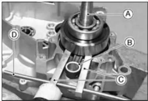

- UsingasuitabletoolontheleftcrankcasetopressA aroundtheholeforthecrankshaft,fitthecrankcase halvestogetherwithapressonthetool.
NOTE
○ Constantlycheckthealignmentofthetwocrankcase halves, and the positionofthetransmissionshafts, and shiftdrum. Thefrontandrearofthecrankcasemustbe pushedtogetherevenly.

natural_image
Mechanical assembly diagram showing internal components and a labeled section A (no readable text or symbols)- Removethecrankshaftjigfromtheflywheels.
- Tightenthecrankcaseboltsstartingwiththeonesaround thecrankshaft,andthenthefartherones.
Torque - Crankcase Bolts: 8.8 N·m (0.90 kgf·m, 78 in·lb)
- Checktoseethatthecrankshaft,driveshaft,andoutput shaftallturnfreely(intheneutralposition).
★ Ifthecrankshaftwillnotturn, probablythecrankshaft is not centered; taptheappropriateendofthecrankshaft withamallettorepositionit. - Spinningtheoutputshaft, shiftthetransmissionthrough allthegearstomakecertainthereisnobindingandthat allthegearsshiftproperly.
- Installthepartsremovedinthereverseorderofremoval, andrefertotheappropriatechapters.
○ReplacetheO-ringontheoutputshaftwithanewone.
7-10 ENGINEBOTTOMEND/TRANSMISSION
Crankshaft, ConnectingRod
CrankshaftRemoval
- Splitthecrankcase(seeCrankcaseSplitting).
- Removethetransmissionshafts(seeTransmissionShaftRemoval).
- Usingapress,removethecrankshaftfromtheright crankcase.
○ Ifthebearingsstayonthecrankshaftwhensplittingthe crankcaseorremovingthecrankshaftfromtheright crankcase,removethebearingsfromthecrankshaftwith abearingpullerAandadapter[B].
SpecialTools-BearingPuller:57001-158
BearingPullerAdapter:57001-136
CrankshaftInstallation
- Wheninstallingthecrankshaftbearings[B],applyhigh temperaturegreasetotheoutersidesofthebearings, andthenpressthemintothecrankcaseusingthebearing driverAuntilthebearingbottomsagainstthestep.
○ Positionthecrankcasehalfsothatthemainbearinghousingisseatedonasuitablepressfixture.
○ Installthecrankshaftbearingsothatthesealedsidein(to theoilseal[C]side).
SpecialTool-BearingDriverSet:57001-1129
- InsertthecrankshaftjigAbetweenthecrankshaftfly-wheels opposite the connecting rod big end to protect flywheelalignmentasshown, and using asuitabletool [B]ontheleftcrankcasetopressaroundtheholeforthe crankshaft.
When pressing, position the jig in the crank case opening so the jig does no that the crank case.
SpecialTool-CrankshaftJig:57001-1439
- Apply2-strokeoiltotheconnectingrodbigendbearing.
CrankshaftDisassembly
Sinceassemblyofthecrankshaftdemandsexactingtolerances, thedisassemblyandreassemblyofthecrankshaft canonlybedonebyashophavingthenecessarytoolsand equipment.
- Ifitshouldbenecessarytodisassemblethecrankshaft, useapresstoremovethecrankpin.
CrankshaftAssembly
Sincetheassemblyofthecrankshaftdemandsexacting tolerances, thedisassemblyandreassemblyofthecrankshaftcanonlybedonebyashophavingthenecessarytools andequipment.
- ReassemblethecrankshaftaccordingtothestandardtolerancesinSpecifications.
○Connectingrodbend,twist
○Connectingrodbigendradialclearance.
○ Cold-fittingtolerancebetweenencrankpinandflywheels.
○Sideclearancebetweentheconnectingrodbigendand oneofflywheels.
○ Crankshaftrunout.

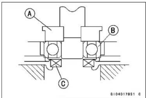

Crankshaft, ConnectingRod
ConnectingRodBigEndRadialClearance Inspection
- SetthecrankshaftinaflywheelalignmentjigoronV blocks, and placeadialgaugeagainsttheconnectingrod bigend.
- Pushtheconnectingrodfirsttowardsthegaugeandthen intheoppositedirection. Thedifferencebetweenthetwo gaugereadingsisteradialclearance.
★Iftheradialclearanceexceedstheservicelimit,thecrankshaftshouldbeeitherreplacedordisassembledandthe crankpin,needlebearing,andconnectingrodbigendexaminedforwear.
ConnectingRodBigEndRadialClearance
Standard: 0.025\~0.037mm
ServiceLimit: 0.09mm
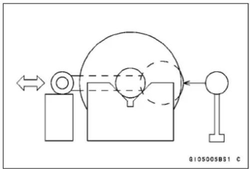
natural_image
Pure mechanical diagram showing a pulley system with no text or symbolsConnectingRodBigEndSeizureInspection
★Incaseofseriousseizurewithdamagedflywheels,the crankshaftmustbereplaced.
★Incaseoflessseriousdamage,disassemblethecrankshaftandreplacethecrankpin,needlebearing,side washers,andconnectingrod.
ConnectingRodBigEndSideClearance Inspection
- MeasurethesideclearanceAoftheconnectingrodwith athicknessgauge.
★Iftheclearanceexceedstheservicelimit,replace the crankshaft.
ConnectingRodBigEndSideClearance
Standard: 0.35\~0.45mm
ServiceLimit: 0.65mm
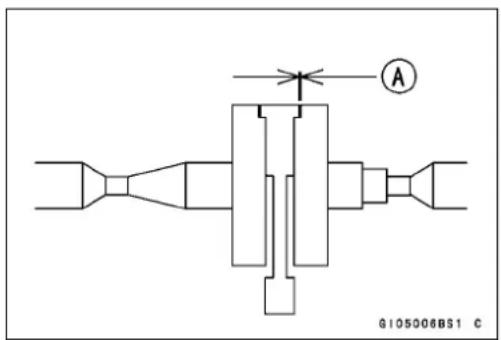
CrankshaftRunoutInspection
- SetthecrankshaftinaflywheelalignmentjigoronV blocks, and placeadialgaugeagainststhepointsindicated.
- Turnthecrankshaftslowly. Themaximumdifferencein gaugereadingsisthecrankshaftrunout.
★ Iftherunoutateitherpointexceedstheservicelimit, align theflywheelssothattherunoutfallswithintheservice limit.

CrankshaftRunout
Standard: Not more than 0.03 mm
ServiceLimit: 0.05mm
7-12 ENGINEBOTTOMEND/TRANSMISSION
Crankshaft, ConnectingRod
CrankshaftAlignmentInspection
- In the case of horizontal misalignment, which is most common, strikethe projecting grimof the flywheel with a plastic, softlead, or brasshammer as indicated in the figure.
- Rechecktherunoutwithadialgauge,repeatingthe processuntiltherunoutfallswithintheservicelimit.
○ Verticalmisalignment is corrected either by driving a wedge in between the fly wheels or by squeezing the fly wheel rims in advance, depending on then nature of the misalignment. In cases of both horizontal and vertical misalignment, correct the horizontal misalignment first.
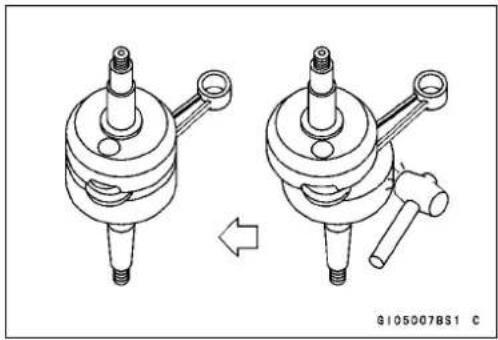
natural_image
Technical illustration of a mechanical assembly showing two views of a cylindrical component with threaded ends and a shaft (no text or symbols)NOTICE
Don'thammertheflywheelatpoint"A".
★ Ifflywheelmisalignmentcannotbecorrectedbytheabove method,replacecrankpinorthecrankshaftitself.
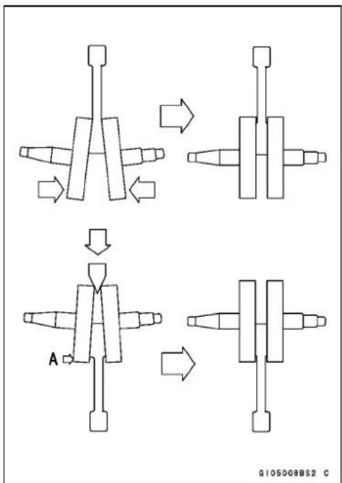
flowchart
graph TD
    A["Step 1: Initial mechanical component"] --> B["Step 2: Rotation of a mechanical part"]
    B --> C["Step 3: Pulling mechanism"]
    C --> D["Step 4: Final assembly with labeled component 'A'"]
    style A fill:#f9f,stroke:#333
    style B fill:#ccf,stroke:#333
    style C fill:#cfc,stroke:#333
    style D fill:#fcc,stroke:#333
Transmission
ShaftRemoval
- Splitthecrankcase(seeCrankcaseSplitting).
- PullofftheshiftrodsA, and disengagetheshiftfork guidepinsfromtheshiftdrumgrooves.
- Removetheshiftdrum[B]
- Removetheshiftforks[C]fromthetransmissiongears.
- Takeoutthedriveshaft[D]andoutputshaft[E]together, withtheirgearsmeshed.
ShaftInstallation
- HoldthedriveshaftAandoutputshaft[B]together,with theirgearsmeshed,andfitthemintotherightcrankcase half.
- Toinstalltheshiftforksandshiftdrum,seetheShiftDrum andForkInstallation.
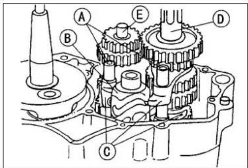
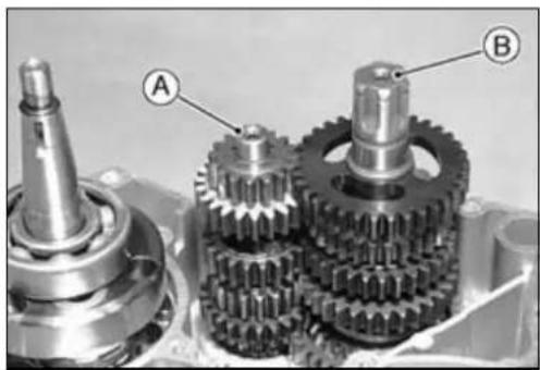
natural_image
Mechanical gear assembly with labeled components A and B (no text or symbols beyond labels)ShaftDisassembly
- Removethetransmissionshafts(seeShaftRemoval).
- Usingcirclipplierstoremovethecirclips,disassemblethe transmissionshaft.
SpecialTool-OutsideCirclipPliers:57001-144
ShaftAssembly
- Applytransmissionoilliberallytothetransmissionshaft, gearsandbe arings.
- Replaceanycirclipsthatwereremovedwithnewones. ○AlwaysinstallcirclipsAsothattheopening[B]isaligned withasplinegroove[C].
SpecialTool-OutsideCirclipPliers:57001-144

- Thedriveshaftgearscanbeidentifiedbysize;thesmall-estdiametergearis1stgear,andthelargestis6th.Be surethatallpartsareputbackinthecorrectsequence, andfacingtheproperdirection,andthatallcirclipsand thewashersareproperlyinplace.
A1stGear(13T;partofdriveshaft)
[B]6thGear(24T; plainsidefacesright)
[C]3rd/4thGear(18T/21T;largergearfacesleft)
[D]5thGear(23T; plainsidefacesleft)
[E]2ndGear(16T;eithersidemayfacein)
[F]Circlip(1.2×15×19)
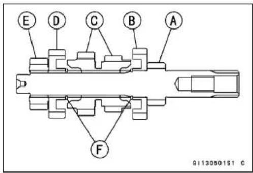
Transmission
- The output shaft gears can be identified by size; the largest diameter gear is 1st gear, and the smallest is 6th. Besure that all parts are put back in the correct sequence and facing the proper direction, and that all circlips are properly in place.
A2ndGear(34T; dogrecessesfaceright)
[B]5thGear(28T;forkgroovegoestotherightsideof thegearteeth)
[C]4thgear(30T; dogrecessesfaceleft)
[D]3rdgear(31T; dogrecessesfaceright)
[E]6thgear(26T;forkgroovegoestotheleftsideofthe gearteeth)
[F]1stgear(37T; plainsidefacesright)
[G]Circlip(1.2×18)
[H]Circlip(1.2×18×23.5)
- Check that each gear spins or slides freely on the transmission shaft without binding after assembly.


ShiftDrumandForkInstallation
- Applyalittletransmissionoiltotheshiftforkears, and fit theshiftforksintothegeargrooves.
ShiftForkIdentification
| Driveshaft3rdgearand4th gearshiftfork[A] | earsareshorterthanthoseof theothertwoshiftforks |
| Outputshaft5thand6thgear shiftforks[B] | earsarelonge rthanthedrive shaft3rd/4rd gearshiftfork |

natural_image
Two metallic mechanical components labeled A and B, shown side by side (no text or symbols on the parts themselves)Transmission
• Installtheshiftdrum.
- Fittheshiftforkguidepinsintothecorrespondingshift drumgrooves.
- Applyalittletransmissionoiltotheshiftrods, and slide themintotheshiftforks.
- Holdingtheshiftdrumwiththesuitabletoolandtighten theshiftdrumoperatingplatebolt.
○Applyanon-permanentlockingagenttotheshiftdrum operatingplatebolt.
Torque-ShiftDrumOperatingPlateBolt:24N·m(2.4 kgf·m,17ft·lb)
ShiftForkBendingInspection
- Visuallyinspecttheshiftforks, and replaceanyforkthatis bent. Abentforkcouldcausedifficultyinshifting, orallow thetransmissiontojumpoutofgearwhenunderpower. A90°
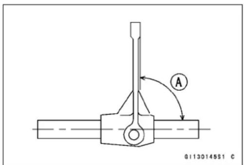
ShiftFork/GearGrooveWearInspection
- MeasurethethicknessoftheshiftforkearsA, and measurethewidth[B]oftheshiftforkgroovesinthetransmissiongears.
★ Ifthethicknessofashiftforkearislessthantheservice limit, theshiftforkmustbereplaced.
ShiftForkEarThickness
Standard: 3.90\~4.00mm
ServiceLimit: 3.80mm

★Ifagearshiftforkgrooveiswornovertheservicelimit, thegearmustbereplaced.
ShiftF orkGrooveWidth
Standard:4.05\~4.15mm
ServiceLimit:4.25mm
ShiftForkGuidePin/ShiftDrumGrooveWear Inspection
- MeasurethediameterAofeachshiftforkguidepin,and measurethewidth[B]ofeachshiftdrumgroove.
★ Iftheguidepinonanyshiftforkislessthantheservice limit, theforkmustbereplaced.
ShiftForkGuidePinDiameter
Standard: 5.90\~6.00mm
ServiceLimit: 5.80mm

★Ifanyshiftdrumgrooveiswornovertheservicelimit,the drummustbereplaced.
ShiftDrumGrooveWidth
Standard: 6.05\~6.20mm
ServiceLimit: 6.25mm
Transmission
GearDamageInspection
- Visuallyinspectthegearteethonthetransmissiongears.
★Repairlightlydamagedgearteeethwithanoilstone. The gearmustbereplacediftheteetharebadlydamaged.
★ Whengearisrepairedorreplaced, thedrivinggearshould also be inspected and repaired or replaced if necessary.
GearDog/GearDogHoleDamageInspection
- VisuallyinspectthegeardogsAandgeardogholes[B].
★Replaceanydamagedgearsorgearswithexcessively worndogsordogholes.
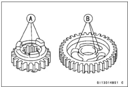
natural_image
Technical illustration of two gear assemblies labeled A and B, showing internal components and alignment lines (no text or symbols beyond labels)BallBearingWearInspection
- Checktheballbearingonthecrankcase.
★ Sincetheballbearingsaremadetoextremelyclosetolerances, thewearmustbejudgedbyfeelratherthanmeasurement. Cleaneachbearinginahighflash-pointsolvent, dryit(donotspinthebearingwhileitisdry), andoil itwithtransmissionoil.
○ Spinthebearingbyhandtocheckitscondition.
★ Ifthebearingisnoisy, does not spinsmoothly, or has any roughspots, replace it.
Wheels/Tires
TableofContents
Exploded View 8-2
Specifications 8-3
Wheels (Rims) 8-4
Front Wheel Removal 8-4
Front Wheel Installation 8-4
Rear Wheel Removal 8-5
Rear Wheel Installation 8-6
Wheels Inspection.... 8-7
Spoke Inspection 8-7
Rim Inspection 8-8
Axle Inspection.... 8-8
Tires 8-9
AirPressureInspection/Adjustment....8-9
Tires Inspection 8-9
Tire Removal 8-10
Tire Installation.... 8-11
Hub Bearings.... 8-12
Hub Bearing Removal 8-12
Hub Bearing Installation 8-12
Bearing Inspection 8-13
ExplodedView

1.Nipple
2.Spoke
3.FrontTire
4.Rim
5.FrontAxle
6.Swingarm
7.RearTire
8.RearAxle
T1:1.5N·m(0.15kgf·m,13in·lb)
- UsingthejackAundertheframe, and stabilizethemotorcycle.
SpecialTool-Jack:57001-1238 - Placeastandundertheenginetoraisethefrontwheel theground.
- RemovethecotterpinA
- Unscrewtheaxlenut[B].
- RemovetheaxleA, and pulloutthewheel. Takeoff the collar[B] and cap[C] from each side of the fronthub.
NOTICE
Donotlaythewheelonthegroundwiththedisc facingdown. This candamageorwarpthedisc. Placeblocksunderthewheelsothediscdoesnot touchtheground.
- Insertawoodwedgebetweenthediscbrakepads. This preventsthemfrombeingmovedoutoftheirproperposition,shouldthebrakeleverbesqueezedaccidentally.
FrontWheelInstallation
- ApplygreaseAtotheseals.
- Fittheprojectiononthecaptothegrooveonthecollar.
- Installthecaps[B]collars[C]ontheleftandrightsideof thehub. Thecollarsandcapsarethesame.
- Inserttheaxle[D]fromleftside.
- Tightenthefrontaxlenut[E].
natural_image
Mechanical assembly diagram showing a vehicle with labeled component A (no readable text or symbols)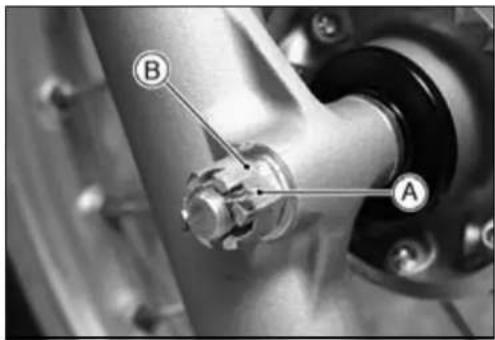


Wheels(Rims)
- InsertanewcotterpinA.
NOTE
○ Wheninsertingthecotterpin,iftheslotsinthenutdo notalignwiththecotterpinholeintheaxle,tightenthe nutclockwise[B]uptonextalignment.
○ Itshouldbewithin30degree.
○ Loosenonceandtightenagainwhentheslotgoespast thenaresthole.
- BendthecotterpinAoverthenut[B].
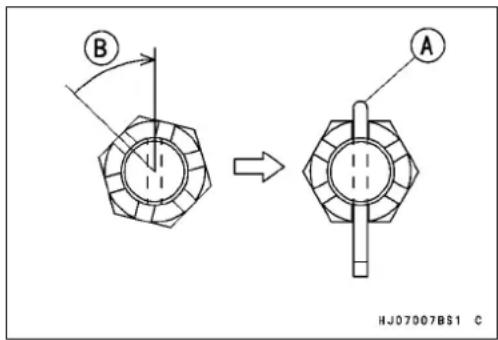

- Removethejack.
- Checkthefrontbrakeforgoodbrakingpowerandno brakedrag.

WARNING
Afterservicing, ittakesseveral applications of the brakelever before the brake pads contact the disc, which could result in increased stopping distance and cause an accident resulting in injury or death. Donot attempt toridethemotor cycle until a firm brake lever is obtained by pumping the lever until the pads are against the disc.
RearWheelRemoval
- Usingthej ackundertheframesothattherearwheelis raisedofftheground.
SpecialTool-Jack:57001-1238
- RemovetheclipAfromthemasterlinkusingpliers,and freethedrivechain[B]fromtherearsprocket.
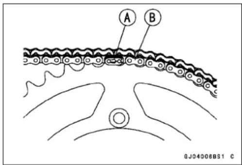
Wheels(Rims)
- RemovethecotterpinA.
- Removetheaxlenut[B].
- Pullouttheaxle[C].
- Movetherearwheelbackwiththerearcaliperinstalled.
- Takeoffthecollarandcapfromtheeachsideoftherear hub.
NOTICE
Donotlaythewheelonthegroundwiththedisc facingdown. This candamageorwarpthedisc. Placeblocksunderthewheelsothediscdoesnot touchtheground.
- Insertawoodwedgebetweenthebrakepads. This preventsthemfrombeingmovedoutoftheirproperposition, shouldthebrakepedalbesqueezedaccidentally.
RearWheelInstallation
- FitthebrakeholderstopAagainstthestopprojection [B]ontheswingarm.
- ApplygreaseAtotheseals.
- Fittheprojectiononthecaptothegrooveonthecollar.
- Installthecaps[B]andcollars[C]ontheleft(longercollar) andright(shortercollar)sideofthehub.
- Installthedrivechain.InstalltheclipAsothattheclosed endofthe"U"[B]pointsinthedirectionofchainrotation [C].
- Checkthedrivechainslack(seeFinalDrivechapter).
- Inserttheaxlefromleftsideandtightentherearaxlenut.
Torque - Rear Axle Nut: 79 N·m (8.0 kgf·m, 58 ft·lb)
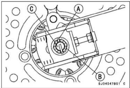

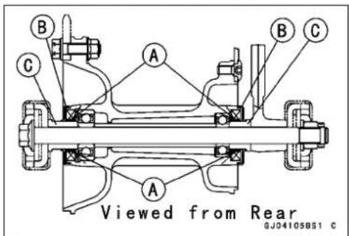

Wheels(Rims)
- InsertanewcotterpinA.
NOTE
○ Wheninsertingthecotterpin,iftheslotsinthenutdo notalignwiththecotterpinholeintheaxle,tightenthe nutclockwise[B]uptonextalignment.
○ Itshouldbewithin30degree.
○ Loosenonceandtightenagainwhentheslotgoespast thenaresthole.
- BendthecotterpinAoverthenut[B].


- Checktherearbrakeforgoodbrakingpowerandno brakedrag.
WARNING
Afterservicing, ittakesseveral applications of the brakepedal before the brake pads contact the disc, which could result in increased stopping distance and cause an accident resulting in injury or death. Donot attempt toridethemotor cycle until a firm brake pad is obtained by pumping the pedal until the pads are against the disc.
WheelsInspection
- Placethejackundertheframesothatthefront/rearwheel israisedo fftheground.
SpecialTool-Jack:57001-1238
- Spinthewheellightly, and check for roughnessor binding.
★lfro ughnessorbindingisfound,replacethehubbearings. - Visuallyinspectthefrontandrearaxlesfordamage.
★ Ifaxleisdamagedorbent, replaceit.
Spokelnspection
- Checkthatallthespokesaretightenedevenly.
★Ifspoketightnessisunevenorloose,tightenthespoke nipplesevenly.
Torque-SpokeNipples:1.5N·m(0.15kgf·m,13in·lb)
- Checktherimrunout.
WARNING
Amissingspokeplacesanadditionalloadon theotherspokes,whichwilleventuallycause otherspokestobreak,creatingthepotentialfor anaccidentresultinginseriousinjuryor death. Immediatelyreplaceanybrokenspoke(s).
Wheels(Rims)
RimInspection
- Removethewheel, and support it with the tire by the axle.
- Measuretherimrunout, axialA and radial[B], with radial gauge.
★ Iftherimrunoutexceedstheservicelimit, checkthehub bearings. Replacethemiftheyaredamaged.
★ If the problem is not due to the bearings, correct therim warp (runout). Acertain amount of trim warpcan be corrected by recentering therim. Loosensomespokes and tighten part of therim. If therim is badly bent, however, it must bere placed.
RimRunout(withtireinstalled)
Standard:
AxialTIR1.0mmorless
RadialTIR1.0mmorless
ServiceLimit:
AxialTIR2mm
RadialTIR2mm
AxleInspection
- Visuallyinspectthefrontandrearaxlefordamages.
★ Iftheaxleisdamagedorbent,replaceit. - PlacetheaxleinVblocksthatare100mmAapart, and setadialgaugeontheaxleatapointhalfwaybetween theblocks. Turntheaxletomeasuretherunout. The differencebetween the highest and lowest dialreadings is the amount of runout.
★ Ifrunoutexceedstheservicelimit, replacetheaxle.
AxleRunout/100mm
Standard: Under0.1mm
ServiceLimit: 0.2mm

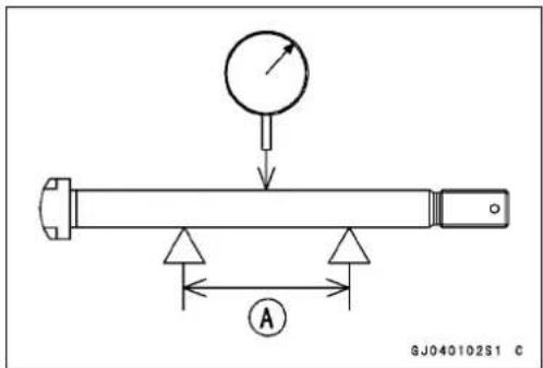
Tires
AirPressureInspection/Adjustment
- UsingtireairpressuregaugeA,measurethetirepressurewhenthetiresarecold.
★Adjustthetireairpressuretosuittrackconditionsand riderpreference, butdonotstraytoofarfromtherecommendedpressure.
| TrackCondition | TirePressure |
| Whenthetrackiswet,muddy,sandy orslippery,reducethetirepressureto increasethetiretreadsurfaceonthe ground. | 80kPa(0.8kgf/cm2,11psi)↑ |
| Whenthetrackispebblyorhard, increasethetirepressuretoprevent damageorpunctures,throughthe tireswillskidmoreeasily. | ↓98kPa(1.0kgf/cm2,14psi) |

TiresInspection
Asthetiretreadwearsdown, thetirebecomesmoresusceptiblethepunctureandfailure.
- Removeanyimbeddedstonesorotherforeignparticles fromthetread.
- Visually inspect the tire for cracks and cuts, replacing the tire in case of baddamage. Swelling or high spots indicate internal damage, requiring tirereplacement.
WARNING
Somereplacementtiresmayadverselyaffecthandlingandcauseanaccidentresultinginserious injuryordeath.Toensureproperhandlingandstability,useonlytherecommendedstandardtiresfor replacement,inflatedtothestandardpressure.

natural_image
Technical line drawing of a tire track with suspension components (no text or symbols)NOTE
○ Checkandbalancethewheelwhenatireisreplaced withanewone.
StandardTire
Front:
Size:60/100-1430M
Make: DUNLOP
Type: D755F, Tube(KX65-A1\~A6)
D756F, Tube
Rear:
Size:80/100-1241M
Make: DUNLOP
Type: D755, Tube(KX65-A1\~A6)
D756, Tube
Tires
TireRemoval
NOTICE
Donotlaythewheelonthegroundwiththedisc facingdown. This candamageorwarpthedisc. Placeblocksunderthewheelsothediscdoes not touchtheground.
- Removethewheelfromthemotorcycle(seeWheelsRemoval).
- Tomaintainwheelbalance, markAthevalvestempositiononthetirewithchalksothatthetirecanbereinstalled inthesameposition.
• Takeoutthevalvecore[B]toletouttheair. - Removethevalvestemnut[C].
○Whenhandlingtherim, be careful not to damage therim flanges. - Removethebeadprotectornut.
- Lubricatethetirebeadsandrimflangesonbothsideswith asoapandwatersolutionorrubberlubricant. Thishelps thetirebeadsslipofftherimflanges.
NOTICE
Neverlubricatewithmineraloil(engineoil)orgasolinebecausetheywillcausedeteriorationofthetire.
-
Breakthebeadsawayfrombothsidesoftherimwiththe beadbreakerA.
SpecialTool-BeadBreakerAssembly:57001-1072 -
Steponthesideofthetireoppositevalvestem, prythe tireofftherimwiththetireironAofthebeadbreaker protectingtheri mwithrimprotectors[B].
SpecialTools-RimProtector:57001-1063
TireIronProtectionoftheBeadBreakerAs-sembly:57001-1072
NOTICE
Takecarenottoi nsertthetireironssodeeplythat thetubegetsdamaged.
- Removethetubewhenonesideofthetireispriedoff.
- Prythetireofftherim.

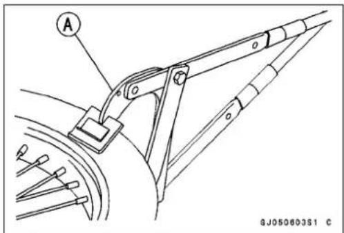

Tires
TireInstallation
- Inspecttherimandtire, and replacethemifnecessary.
- Installthetube.
- Applyasoapandwatersolution,orrubberlubricanttotherimflangeandtirebeads.
- PositionthetireontherimsothatthevalveAisatthetire balancemarkB.
- Insertthevalvestemintotherim, andscrewthenuton loosely.
- Fittherimprotectorsandusetireironstoinstallthetire bead.
NOTE
○ Topreventrimdamage, besuretoplacetherimprotectorsatanyplacethetireironsareapplied.
- Pryonesideofthetirebackontotherim.Fitthebead protectorintothetire.
- Prytheothersideofthetireontotherim, startingatthe sideoppositethevalve.
○Takecarenottoinsertthetireironssodeeplythatthe tubeisdamaged. - Installtheothersideofthetirebeadontotheriminthe samemanner.
- Check that the tube is not pinched between the tire and rim.
- Tightenthebeadprotectornutandvalvestemnut,and putonthevalvecap.
- Checkandadjusttheairpressureafterinstalling.

HubBearings
HubBearingRemoval
- Removethewheel(seeWheelRemoval).
NOTICE
Donotlaythewheelonthegroundwiththedisc facingdown. Thiscandamageorwarpthedisc. Placeblocksunderthewheelsothatthediscdoes nottouchtheground.
- Removetheoilsealsandcirclip.
- Removethehubbearingbytappingevenlyaroundthe bearinginnerraceasshown.
ABar
[B]DistanceCollar
[C]HubBearing
HubBearingInstallation
- Beforeinstallingthewheelbearings,blowanydirtorforeignparticlesoutofthehubwithcompressedairtopreventcontaminationofthebearings.
- InstallthebearingsAbyusingthebearingdriverset[B] whichdoesnotcontactthebearinginnerrace.
SpecialTool-BearingDriverSet:57001-1129
NOTE
○Installthebearingssothatthemarkedside,orthe sealedsidefacesout.
○Pressinthebearingsasfollows.
○WhenthebearingsareinstalledinthefronthubA,press intherightsidebearing[B]untilitisbottomedagainstthe step[C]ofthehub.Andpressinth eleftsidebearing[D] untilitisbottomedagainstthecollar[E].
○WhenthebearingsareinstalledintherearhubA,press intheleft sidebearing[B]untilitisbottomedagainststhe step[C]ofthehub.Andpressintherightsidebearing[D] untilitisbottomedagainststhecollar[E].


HubBearings
- Replacethecirclipandoilsealswithnewones.
- PressintheoilsealsAsothatthesealsurfaceisflush [B]withtheendofthehole.
- Applyhightemperaturegreasetotheoilseallips.
SpecialTool-BearingDriverset:57001-1129[C]
InsideCirclipPliers:57001-143

BearingInspection
NOTE
- Itisnotnecessarytoremoveanybearingsforinspection.Ifanybearingsareremoved,theywillneedtobe replacedwithnewones.
- SpinAitbyhandtocheckitscondition.
★ Ifitisnoisy, does not spins smoothly, or has any rough spots, it must bere placed. - Examinethebearingseal[B]fortearsorleakage.
★Ifthesealistornorisleaking,replacehebearing.

FinalDrive
TableofContents
Exploded View 9-2
Specifications 9-3
Drive Chain.... 9-4
Drive Chain Slack Inspection.... 9-4
Drive Chain Slack Adjustment 9-4
Wheel Alignment Inspection 9-5
Wheel Alignment Adjustment.... 9-5
Drive Chain Wear Inspection 9-5
Drive Chain Lubrication.... 9-6
Drive Chain Removal 9-6
Drive Chain Installation 9-7
Sprockets.... 9-8
Engine Sprocket Removal 9-8
Engine Sprocket Installation 9-8
Rear Sprocket Removal 9-8
Rear Sprocket Installation.... 9-8
Sprocket Wear Inspection.... 9-8
Rear Sprocket Warp Inspection 9-9

GK021268W4 C
-
EngineSprocket
-
OutputShaft
3.Swingarm
4.ChainSlipper
5.ChainGuide
6.Locknut
-
Adjusting Bolt
-
ChainAdjuster
9.DriveChain
10.RearSprocket
11.RearAxle
12.KX65-A6,A6F\~
T1:26N·m(2.7kgf·m,20ft·lb)
DriveChainSlackInspection
- Supportthemotorcycleonitsstand.
- Checkthewheelalignment(seeWheelAlignmentInspection), and adjustitifnecessary(seeWheelAlignmentAdjustment).
NOTE
○Cleanthedrivechainifitisdirty, and lubricateitifit appears dry.
- Rotatetherearwheeltofindthepositionwherethechain istightest.
- Measurethespace(chainslack)Abetweenthechain andtheswingarmattherearofthechainslipperwiththe rearwheelraisedofftheground.
★ Ifthedrivechainslackexceedsthestandard,adjustit.
ChainSlack
Standard:
KX65-A1\~
44\~54mm
A2
KX65-A3\~45\~55mm

DriveChainSlackAdjustment
- LoosentheleftandrightchainadjusterlocknutsA.
-
Removethecotterpin[B]andloosentheaxlenut[C].
★ Ifthechainistootight,backouttheleftandrightchain adjustingbolts[D]evenly,andpushthewheelf forward untilthechainistooloose.
★ Ifthechainistooloose,turnbothchainadjustingbolts evenlyuntilthedrivechainhasthecorrect amountof slack.Tokeepthechainandwheelproperlyaligned,the rearendoftheleftchainadjustersshouldalignwiththe sameswingarmmark[E]astherearen d[F]oftheright chainadjuster. -
Checkthewheelalignment.
- Tightenbothchainadjusterlocknutssecurely.
- Tightentheaxlenu t.
Torque - Rear Axle Nut: 79 N·m (8.0 kgf·m, 58 ft·lb)
- InsertanewcotterpinA.
NOTE
When inserting the cotterpin, if the slots in then but do not align with the cotterpinhole in the axle, tighten the nut clockwise [B] uptonextalignment.
○Itshouldbewithin30degree.
○Loosenonceandtightenagainwhentheslotgoespast thenaresthole.
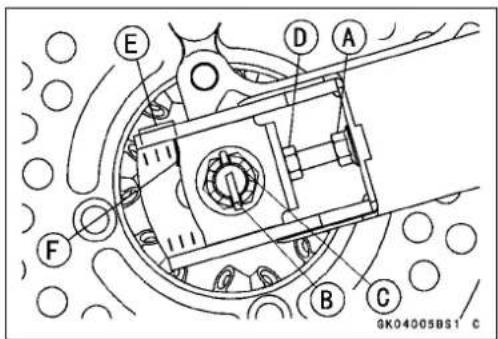
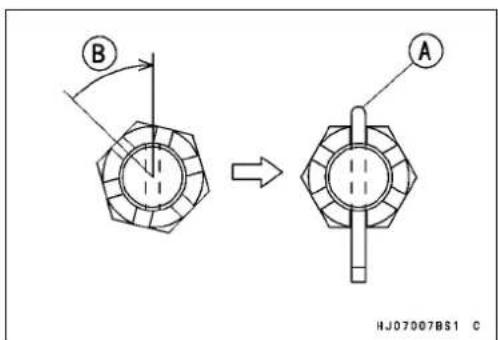
DriveChain
- BendthecotterpinAoverthenut[B].

- Rotatethewheel, measure the chainslack again at the tightest position, and readjustif necessary.

WARNING
Alooseaxlenutcanleadtoanaccidentresultingin seriousinjuryordeath. Tightentheaxlenuttothe propertorqueandinstallanewcotterpin.
NOTE
○ Inwetandmuddyconditions, mudstickstothecchain andsprocketsresultinginanoverlytightchain, and the chainmaybreak. Topreventthis, adjustthechainto54 \~ 64mm(KX65-A3 \~, 55 \~ 65mm)ofslackwhenever necessary.
WheelAlignmentInspection
- CheckthattherearendAoftheleftchainadjuster[B] alignswiththesameswingarmmark[C]astherightchain adjuster.
NOTE
○ Wheelalignmentcanalsobecheckedusingthe straightedgeorstringmethod.

WARNING
Misalignmentofthewheelwillresultinabnormal wearandmayresultinanunsaferidingcondition. Besurethewheelisproperlyaligned.
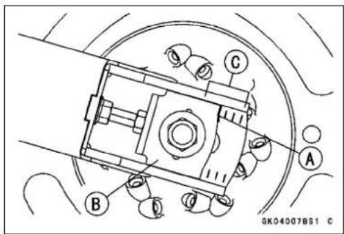
WheelAlignmentAdjustment
These procedures are the same as DriveChainSlack Adjustment.
DriveChainWearInspection
- Rotatetherearwheeltoinspectthedrivechainfordamagedrollers, and loosepinsandlinks.
ABushing
[B]Roller
[C]Pin
[D]PinLink
[E]RollerLink
★Ifthereisanyirregularity,replacethedrivechain.
★Lubricatethedrivechainifitappearsdry.

DriveChain
- Stretchthechaintautbyhanginga98N(10kg,20lb) weightAonthechain.
- Measurethelengthof20links[B]onthestraightpart[C]of thechainfromthepincenterofthe1stpintothepincenter ofthe21stpin.Sincethechainmaywearunevenly,take measurementsatseveralplaces.
Chain20-linkLength
Standard: 254.0\~254.6mm
ServiceLimit: 259mm
★ Ifanymeasurementsexceedtheservicelimit,replace the chain.Also,replacethefro ntandrearsprocketshenthe drivechainisreplaced.

WARNING
Achainthatbreaksorjumpsoffthesprockets couldsnagontheengin esprocketorlockthe rearwheel,severelydamagingthemotorcycleand causingittogooutofcontrol.Inspectthechainfor damageandpro peradjustmentbeforeeachride. Ifchainwearexceedstheservicelimit,replaceit withthestandardchain.
StandardChain
Make: DAIDO
Type: DID420MBK1
Link: 108Links
110Links(KX65-A3\~)
DriveChainLubrication
- If the chain appears especially dirty, it should be cleaned before lubrication with high flash-points solvent.
- Ifaspeciallubricantisnotavailable, aheavyoilsuchas SAE90 is preferred to alighteroil because it will stay on the chain longer and provide better lubrication.
- Applyoiltothesidesoftherollerssothatoilwillpenetrate totherollersandbushings.
OilAppliedAreasA - Wipeoffanyexcessoil.
DriveChainRemoval
- Removetheenginesprocketcover.
- RemovetheclipAfromthemasterlinkusingpliers,and freethedrivechainfromtherearsprocket.
- Removethedrivechainfromthechassis.


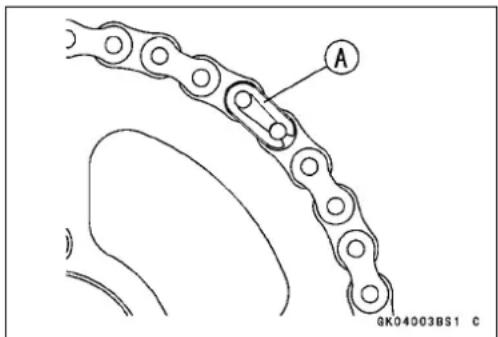
DriveChain
DriveChainInstallation
- Fitthedrivechainbackontothesprocketswiththeends attherearsprocket.
• Installthemasterlinkfromtheframeside. - InstalltheclipAsothattheclosedendofthe"U"[B] pointsinthedirectionofchainrotation[C].
- Adjustthedrivechainslack(seeDriveChainSlackAdjustment).
- Checktherearbrake(seetheBrakeschapter).

Sprockets
EngineSprocketRemoval
- Remove:
MagnetoCover
DriveChainA
- Removethecirclip[B], and pullofftheenginesprocket [C].
SpecialTool-OutsideCirclipPliers:57001-144
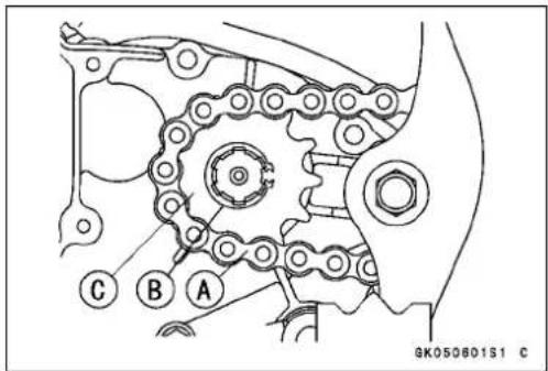
EngineSprocketInstallation
- Replacethecirclipwithanewone.
- Install the circlip so that the tooth is aligned with aspline groove.
SpecialTool-OutsideCirclipPliers:57001-144
RearSprocketRemoval
- Removetherearwheel(seeWheels/Tireschapter).
NOTICE
Donotlaythewheelonthegroundwiththedisc facingdown. This candamageofwarpthedisc. Placeblocksunderthewheelsothatthed iscdoes nottouchtheground.
- UnscrewtherearsprocketboltsA, andremovetherearsprocket[B].
RearSprocketInstallation
- Installtherea rsprocketAsothatthemarkedside[B] facesout.
- Tightentherearsprocketbolts.
Torque-RearSprocketBolts:26N·m(2.7kgf·m,20ft·lb)

SprocketWearInspection
- Visuallyinspectthefrontandrearsprocketteeth.
★ Iftheteetharewornasillustrated, replacethesprocket, and inspect the drivechain and engines procket (see DriveChainWearInspection).
WornTooth(EngineSprocket)A
WornTooth(RearSprocket)[B]
DirectionofRotation[C]
NOTICE
Ifasprocketrequiresreplacement,thedrivechain isprobablywornalso.Uponreplacingtherear sprocket,inspectthechainandenginesprocket.
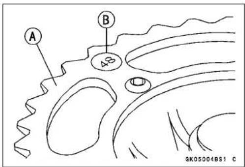

Sprockets
RearSprocketWarpInspection
• Usingthejack, raisetherearwheelofftheground.
SpecialTool-Jack:57001-1238
- SetadialgaugeAagainsttherearsprocket[B]nearthe teethasshownandrotate[C]therearwheeltomeasure thesprocketrunout(warp). Thedifferencebetween the highestandlowestdialgaugereadingsistheamountof runout(warp).
★ Iftherunoutexceedstheservicelimit, replacetherear sprocket.
RearSprocketWarp
Standard:
Under0.4mm
ServiceLimit:
0.5mm

Brakes
TableofContents
Exploded View 10-2
Specifications 10-4
Brake Lever, Brake Pedal 10-5
Brake Lever Play Adjustment.... 10-5
BrakePedalPosition/PedalPlayAdjustment....10-5
Brake Pedal Removal 10-5
Brake Pedal Installation 10-6
Brake Fluid 10-7
Fluid Level Inspection 10-8
Fluid Change.... 10-8
Bleeding the Brake Line.... 10-10
Caliper 10-12
Caliper Removal 10-12
Caliper Installation 10-12
Caliper Disassembly 10-13
Caliper Assembly 10-13
Fluid Seal Damage Inspection.... 10-14
DustSealandCoverDamageInspection....10-14
Piston Cylinder Damage Inspection.... 10-14
Caliper Holder Shaft Wear Inspection.... 10-14
Brake Pad Removal 10-15
Brake Pad Installation 10-15
Brake Pad Inspection.... 10-15
Master Cylinder 10-16
Front Master Cylinder Removal 10-16
Front Master Cylinder Installation 10-16
Rear Master Cylinder Removal.... 10-17
Rear Master Cylinder Installation.... 10-17
Front Master Cylinder Disassembly 10-17
Rear Master Cylinder Disassembly.... 10-18
Master Cylinder Assembly 10-18
MasterCylinderInspection(VisualInspection)....10-19
Brake Disk 10-20
Brake Disc Inspection 10-20
Brake Hose.... 10-21
Brake Hose Removal/Installation 10-21
Brake Hose Inspection.... 10-21

- FrontBrakeReservoir
2.BrakeLever - BrakeHose
- Clamps
5.FrontCaliper
6.BrakePad - Piston
8.FrontDisc
9.KX65A9F\~
T1:25N·m(2.5kgf·m,18ft·lb)
T2:8.8N·m(0.90kgf·m,78in·lb)
T3:7.8N·m(0.80kgf·m,69in·lb)
T4:18N·m(1.8kgf·m,13ft·lb)
T5:9.8N·m(1.0kgf·m,87in·lb)
T6:4.9N·m(0.50kgf·m,43in·lb)
L: Applyanon-permanentlockingagent.
R:ReplacementParts
Si:ApplySiliconegrease.
ExplodedView

- RearBrakeReservoir
- RearMasterCylinder
3.BrakeHose - BrakePedal
- RearCaliperCover
6.RearCaliper
7.Piston
8.BrakePad
9.RearDisc
T1:25N·m(2.5kgf·m,18ft·lb)
T2:9.8N·m(1.0kgf·m,87in·lb)
T3:7.8N·m(0.80kgf·m,69in·lb)
T4:18N·m(1.8kgf·m,13ft·lb)
G:Applyhightemperaturegrease.
L: Applyanon-permanentlockingagent.
R:ReplacementParts
Si:ApplySiliconegrease.
Specifications
| Item | StandardServiceLimit | |
| BrakeAdjustmentLeverPlayAdjustable(tosuitrider)-- -- | ||
| BrakeFluidRecommendedDiscBrakeFluid:-- --Type | DOT3orDOT4 | --- |
| BrakePadsLiningThickness:Front4.5mm0.7mmRear4.5mm0.7mm | ||
| BrakeDiscThickness:Front2.80~ 3.20mm2.5mmRear2.80~ 3.20mm2.5mmRunoutNotmorethan0.15mm0.3mm |
SpecialTools-InsideCirclipPliers:57001-143
Jack: 57001-1238
BrakeLever, BrakePedal
BrakeLeverPlayAdjustment
- AdjustthefrontbrakeleverAtosuityou.
- Slidethebrakeleverdustcover[B]outofplace.
- Loosentheadjusterlocknut[C]andturntheadjuster[D]toeitherside.
• Afteradjustment, tightenthelocknut.

WARNING
Animproperlyadjustedbrakecoulddragandcause thebraketooverheat,damagingthebrakeassemblyandpossiblylockingtherearwheel,resultingin lossofcontrol.Alwaysmaintaintheproperbrake adjustment.
BrakePedalPosition/PedalPlayAdjustment
Thebrakepedalpositionandpedalplayshouldnotbe adjusted. Thereisnopedalpositionadjustmentdevice assuch. Theonlyadjustmentismastercylinderpushrod length.
NOTE
○ Usuallyitisnotnecessarytoadjustthepushrodlength, butalwaysadjustitwhentherearmastercylinderAis disassembled.
○ Whenthebrakepedalisinitsrestposition, measure thelength[B]indicatedinthefigure.
B:80.5mm
C:PushRodLocknut
★ Ifthelengthisnotwithinthespecifiedlength,adjustthe clevisAasfollows.
○Loosenthepushrodlocknut[B].
○Pulloutthecotterpin[C]andthejointpin[D].
○Turntheclevistoobtainthespecifiedlength.
○Tightenthelocknut.
Torque-PushRodLocknut:18N·m(1.8kgf·m,13ft·lb)
○Installthejointpinandnewcotterpin.
NOTE
○ Ifthepedalpositionisincorrectafteradjusting the mastercylinderpushrod, thebrakepedalmaybeformed orincorrectlyinstalled.
BrakePedalRemoval
- Remove: CotterPinA
JointPin[B]
Washer


GL04002BS1 C
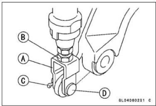

GL04000BS1 C
10-6BRAKES
BrakeLever, BrakePedal
- RemovethebrakepedalmountingboltAandtakeoff thebrakepedalandreturnspring[B].

BrakePedallInstallation
- CheckthepedalO-ringforsignsofdamage.Ifnecessary, replacethemwithnewone. - Applyhightemperaturegreasetotheshaftportionofthe brakepedal,andinstallthepedalwithreturnspringonto theframe.
Torque-BrakePedalMountingBolt:25N·m(2.5kgf·m,18ft·lb)
- Checkthebrakepedalposition.
- Installthejointpin, washerandanewcotterpin.

WARNING
When working with the disc brake, observ the precautions listed below.
- Neverreuseoldbrakefluid.
- Donotusefluidfromacontainerthathasbeenleft unsealedorthathasbeenopenforalongtime.
- Donotmixtwotypesandbrandsoffluidforusein thebrake. Thislowersthebrakefluidboilingpoint andcouldcausethebraketobeineffective. It may also cause therubberbrakepartstodeteriorate.
- Don'tleavethereservoircapofforanylengthof timetoavoidmoisturecontaminationofthefluid.
- Don't changethe fluid in therain or when a strong windis blowing.
- Except forthediscpadsanddisc, use only disc brake fluid, isopropyl alcohol, orethyl alcohol for cleaning brake parts. Donot use any other fluid for cleaning these parts. Gasoline, engine oil, or any other petroleum distillate will cause deterioration of the rubber parts. Oil spilled on any part will be difficult to wash off completely and while eventually deteriorate the rubber used in the disc brake.
- When handling the discpadsordisc, be careful that nodiscbrakefluidoranyoilgetsonthem. Cleanoff any fluidorolthatinadvertently gets on the pads or disc with a high flash-points solvent. Donotuseone which will leave an oily residue. Replacethepads with new ones if they cannot be cleaned satisfactorily.
- Brake fluid quickly ruins painted surfaces; any spilledfluidshouldbecompletelywipedupimmediately.
- If any of the brakeline fittings or the bleed valve is opened at any time, the AIR MUST BE BLED FROM THE BRAKELINE.
BrakeFluid
FluidLevelInspection
Inaccordance with the Periodic Maintenance Chart, inspect the brake fluid level in the front and rear brake fluid reservoirs.
- CheckthebrakefluidlevelinthefrontbrakereservoirA.
NOTE
○Holdthereservoirhorizontalwhencheckingbrakefluid level.
○Thefrontreservoirmustbekeptabovethelowerlevel line[B]. If the fluid level in frontreservoir is lower than the lower level line, fill the reservoir to the upper level line. Inside the frontreservoir is stopped and showing the upper level line[C].
- TherearreservoirAmustbekeptmorethanhalffullwith brakefluid.Iftheamountofbrakefluidisinsufficient,add brakefluid.

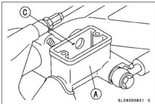

natural_image
Close-up of a mechanical component with a labeled section marked 'A' (no readable text or symbols beyond the label)FluidChange
InaccordancewiththePeriodicMaintenanceChart, changethebrakefluid. Thebrakefluidshouldalsobe changedifitbecomescontaminatedwithdirtorwater. Furthermore, thebrakefluidshouldbechangedtobleed theairquicklyandcompletelywheneverthebrakeline partsareremoved.

WARNING
Mixingbrandsandtypesofbrakefluidcanreduce thebrakesystem'seffectivenessandcauseanaccidentresultinginjuryordeath.Donotmixtwo brandsofbrakefluid.Changethebrakefluidinthe brakelinecompletelyifthebrakefluidmustbere-filledbutthetypeandbrandofthebrakefluidthat isalreadyinthereservoirareunidentified.
RecommendedDiscBrakeFluid
Type:
DOT3orDOT4
BrakeFluid
NOTE
○ Theproceduretochangethefrontbrakefluidisasfollows. Changingtherearbrakefluidisthesameasfor thefrontbrake.
- Levelthebrakefluidreservoir.
- Removethereservoircap.
- RemovetherubbercapAonthebleedvalve[B].
- Attachaclearplastichosetothebleedvalveonthe caliper, and run the other end of the hose into a container.
- Changethebrakefluidasfollows:
○Repeatthisoperationuntilfreshbrakefluidcomesout fromtheplastichoseorthecolorofthefluidchanges.
- OpenthebleedvalveA
2.Applythebrakeandholdit[B]
-
Closethebleedvalve[C]
-
Releasethebrake[D]
○Fillthereservoirwithfreshspecifiedbrakefluid.
NOTE
○ Thefluidlevelmustbecheckedoftenduringthechangingoperationandreplenishedwithfreshbrakefluid. If thefluidinthereservoirrunsoutanytimeduringthe changingoperation,thebrakeswillneedtobebled sinceairwillhaveenteredthebrakeline.
- Removetheclearplastichose.
- Tightenthebleedvalves, and installtherubbercap.
Torque - Caliper Bleed Valve: 7.8 N·m (0.8 kgf·m, 69 in·lb)
- Afterchangingthefluid, checkthebrakeforgoodbraking power, nobrakedrag, andnofluidleakage.
★Ifnecessary,bleedtheairfromthelines.
• Installthereservoircap.


NOTE
○ Follow the procedure below to install therear brake reservoir cap correctly.
○ First, tightentherearbrakereservoircap[B]clockwise [C]byhanduntilslightresistanceisfeltindicatingthat thecapsseatedonthereservoirbody, thentightenthe capanadditional1/6turn[D]whileholdingthebrake fluidreservoirbodyA.

BrakeFluid
BleedingtheBrakeLine
Thebrakefluidhasaverylowcompressioncoefficientso thatalmostallthemovementofthebrakeleverorpedal istransmitteddirectlytothecaliperforbrakingaction.Air, however,iseasilycompressed.Whenairentersthebrake lines,brakeleverorpedalmovementwillbepartiallyused incompressingtheair.Thiswillmaketheleverorpedalfeel spongy,andtherewillbealossinbrakingpower.

WARNING
Airinthebrakelinesdiminishbrakingperformance andcancauseanaccidentresultinginjuryor death.Ifthebrakeleverhasasoftor"spongy"feelingmushywhenitisapplied,theremightbeairin thebrakelinesorthebrakemaybefective.Do notoperatethevehicleandservicethebrakesystemimmediately.
NOTE
○Theproceduretobleedthefrontbrakelineisasfollows. Bleedingtherearbrakelineisthesameasforthefront brake.
- Removethereservoircap, and check that there is plenty off fluid in the reservoir. - With the reservoir cap off, slowly pump the brake lever severaltimes until no air bubbles can be seen rising up through the fluid from the holes at the bottom of the reservoir.
○ Bleedtheaircompletelyfromthemastercylinderbythis operation.
• Installthereservoircap.
- Attachaclearplastichosetothebleedvalveonthe caliper, and run the other end of the hose into a container.
- Bleedthebrakelineandthecaliperasfollows:
○ Repeat this operation until nomore air can be seen coming out into the plastic chose.
- Pumpthebrakeleveruntilbecomeshard, and apply thebrakeandholditA.
- Quickly open and closethe bleed valve while holding the brake applied [B].
- Releasethebrake[C].
NOTE
○Thefluidlevelmustbecheckedoftenduringthebleedingoperationandreplenishedwithfreshbrakefluidas necessary. Ifthefluidinthereservoirrunsalmostout anytimeduringbleedingoperation,thebleedingoperationmustdoneoveragainfromthebeginningsince airwillhaveenteredtheline.
○ Tapthebrakehoselightlyfromthecalipertothereservoirforeasierbleeding.

BrakeFluid
- Removetheclearplastichose.
- Tightenthebleedvalves, and installtherubbercap.
Torque-CaliperBleedValve:7.8N·m(0.8kgf·m,69in·lb) - Checkthefluidlevel.
- Afterbleedingisdone, checkthebrakeforgoodbraking power, nobrakedrag, andnofluidleakage.

WARNING
Afterservicing, ittakesseveral applications of the brakelever before the brake pads contact the disc, which could result in increased stopping distance and cause an accident resulting in injury or death. Donot attempt toridethemotor cycle until a firm brake lever is obtained by pumping the lever until the pads are against the disc.
Caliper
CaliperRemoval
FrontBrake
- LoosenthebanjoboltAsoasnottospillbrakefluid.
- Removethecalipermountingbolts[B].
- Removethebanjoboltandtakeoffthebrakehosefrom thecaliper[C].
- Ifthecaliperistobedisassembledafterremovalandif compressedairisnotavailable,removethepistonusing thefollowingstepsbeforedisconnectingthebrakehose fromthecaliper.
○Removethepads.
○Pumpthebrakelevertoremovethepiston.
RearBrake
- Unbolttheguardboltsandremovetherearcaliperguard.
- LoosenthebanjoboltAsoasnottospillbrakefluid.
- Removethecalipermountingbolts[B].
- Removethebanjoboltandtakeoffthebrakehosefrom thecaliper[C].
- Ifthecaliperistobedisassembledafterremovalandif compressedairisnotavailable,removethepistonusing thefollowingstepsbeforedisconnectingthebrakehose fromthecaliper.
○Removethepads.
○Pumpthebrakelevertoremovethepiston.
NOTICE
Immediatelywipeupanybrakefluidthatisspilled.
CaliperInstallation
- Tightenthebrakepadbolt siftheywereremoved.
Torque-BrakePadBolts:18N·m(1.8kgf·m,13ft·lb) - Installthecaliper, and the brakehoselowerend.
○Replacethewasherstha tareoneachsideofhosefitting withnewones.
○Installthebrakehoselowerendsothatthewhitepaint markonitfacesbac kward.
Torque-CaliperMountingBolts:25N·m(2.5kgf·m,18ft·lb) BrakeHoseBanjoBolt:25N·m(2.5kgf·m,18ft·lb)
- Bleedthebrakeli ne(seeBleedingtheBrakeLine).
- Checkthebrakeforgoodbrakingpower,nobrakedrag, andnofluidleakage.

WARNING
Afterservicing, ittakesseveral applications of the brakeleverorpedal before the brakepads contact the disc, which could result in increased stopping distance and cause an accident resulting in injury or death. Donot attempt toridethemotorcycle until a firm brake leverorpedalis obtained by pumping the leverorpedal until the pads are again sthedisc.


Caliper
CaliperDisassembly
- Removethefront/rearcaliper(seeCaliperremoval).
- Removethepadsandspring(seePadRemoval).
- Removethecaliperholder, shaftrubberfrictionbootand cover.
- Usingcompressedair,removethepiston(s).
○Coverthecaliperopeningwithaclean,heavyclothA.
○Removethepiston(s)bylightlyapplyingcompressedair [B]tothehosejointopening.
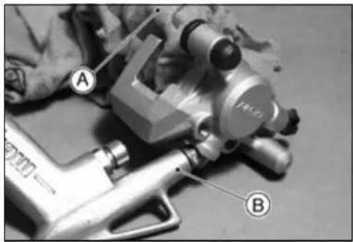
natural_image
Close-up of a mechanical device with labeled parts A and B, no visible text or symbols on the main subject.WARNING
Thepistoninthebrakecalipercancrushhandsand fingers. Neverplaceyourhandorfingersinfrontof thepiston.
NOTE
○ Ifthecaliperistobedisassembledafterremovaland compressedairisnotavailable,removethepiston(s) usingthefollowingthreestepsbeforedisconnectingthe brakehosefromthecaliper.
○Prepareacontainerforbrakefluid, and perform the workaboveit.
○Removethepadsandspring(seePadRemoval).
○Pumpthebrakeleverorpedaltoremovethecaliper piston(s).
- Removethedustseal(s)andfluidseal(s).
- Removethebleedvalveandrubbercap.
CaliperAssembly
- Cleanthecaliperpartsexceptforthepads.
NOTICE
Forcleaningtheparts, useonlydiscbrakefluid, isopropylalcohol, orethylalcohol.
- Tightenthebleedvalvewithrubbercap. Torque - Caliper Bleed Valve: 7.8 N·m (0.8 kgf·m, 69 in·lb)
- Replacethefluidsealwhichisremovedwithnewone. ○Applybrakefluidtothefluidseal[B], andinstallitintothe cylinderbyhand.
- Replacethedustsealwithnewoneifitisdamaged.
○ApplybrakefluidtothedustsealA, and installitintothe cylinderbyhand. - Applybrakefluidtotheoutsideofthepiston[C], and push it into the cylinder by hand.

Caliper
• Installtheanti-rattlespringAinthecaliperasshown.
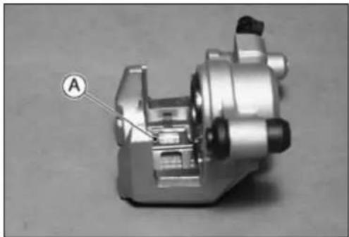
natural_image
Mechanical component with labeled section A, no visible text or symbols- Replacetheshafrubberbootanddustcoveriftheyare damaged.
- Applyathincoatosiliconegreasetothecaliperholder shaftsandholderholes(PBCisaspecialhightemperature,water-resistantgrease).
• Installthepads(seePadsInstallation). - Wipeupanyspilledbrakefluidonthecaliper.
FluidSealDamageInspection
Thefluidsealaroundthepistonmaintainstheproper pad/discclearance.Ifthissealisnotingoodcondition, padwearwillincrease,andconstantpaddragonthedisc willraisebrakeandbrakefluidtemperature.
- Replacethefluidsealsunderanyofthefollowingconditions:(a)fluidleakagearoundthepad;(b)brakesoverheat;(c)thereisalargedifferenceinleftandrightpad wear;(d)thesealisstucktothepiston.Ifthefluidsealis replaced,replacethedustsealaswell.Also,replaceall sealseveryothertimethepadsarechanged.
DustSealandCoverDamageInspection
- Check that the dust seals and covers are not cracked, worn, swollen, or other wisedamaged.
★ Iftheyshowanydamage, replacethem.
PistonCylinderDamageInspection
- Visually inspect the piston and cylinders surfaces.
★Replacethecylinderandpistoniftheyarebadlyscored orrusty.
CaliperHolderShaftWearInspection
Thecaliperbodymustslidessmoothlyonthecaliperholder shafts.Ifthebodydoesnotslidessmoothly,onepadwill wearmorethantheother,padwearwillincrease,andconstantdragonthediscwillraisebrakeandbrakefluidtemperature.
- Checktoseeifthecaliperholdershaftsarenotbadlyworn orstepped,ortherubberbootisnotdamaged.
★ Iftheshaftsorrubberbootaredamaged,replace the shafts,rubberboot,andthecaliperholder.
Caliper
BrakePadRemoval
- LoosenthepadboltsA.
- Removethecaliper[B].
- Removethepadbolts.
•Takeoutthepistonsidepad. - Pushthecaliperholdertowardthepiston, and thenremoveanotherpadfromthecaliperholder.
BrakePadInstallation
- Pushthecaliperpistonsinbyhandasfarastheywillgo.
- InstallthepistonsidepadAfirst,andthenanotherpad[B].
- Tightenthebrakepadbolt.
Torque-BrakePadBolts:18N·m(1.8kgf·m,13ft·lb) - Checkthebrakeforgoodbrakingpower,nobrakedrag, andnofluidleakage.
WARNING
Afterservicing, ittakesseveral applications of the brakeleverorpedal before the brakepads contact the disc, which could result in increased stopping distance and cause an accident resulting in injury or death. Donot attempt toridethemotorcycle until a firm brake leverorpedalis obtained by pumping the leverorpedal until the pads are again sthedisc.
BrakePadInspection
- Checktheliningthicknessandconditionofthepadsineachcaliper.
★lfeitherpadisdamaged,replacebothpadsinthecaliper asaset.
★ IftheliningthicknessAofeitherpadislessthanthe servicelimit[B],replacebothpadsinthecaliperasaset.
LiningThickness
Standard:
Front4.5mm
Rear4.5mm
ServiceLimit:
Front0.7mm
Rear0.7mm
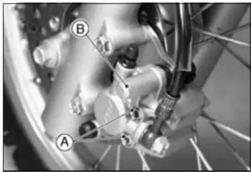

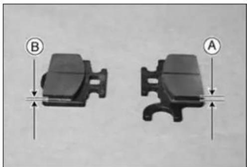
natural_image
Two mechanical component diagrams labeled A and B, showing different mounting features with directional arrows (no text or symbols beyond labels)NOTICE
Brakefluidquicklyruinspaintedorplasticsurfaces;anyspilledfluidshouldbecompletelywiped upimmediately.
FrontMasterCylinderRemoval
- RemovethebanjoboltAtodisconnecttheupperbrake hosefromthemastercylinder(seeBrakeHoseRemoval/Installation).
- When removing the brakehose, temporarily secure the endofthe brakehosetosome high placeto keep fluid lossto a minimum.
- Unscrewthemastercylinderclampbolts[B], and takeoff themastercylinder[C] as an assembly with the reservoir and brakelever.
FrontMasterCylinderInstallation
- Positionthemastercylindersothatthepartingli neAof themastercylinderclampalignwiththepunchmark[B] onthehandlebar.
- ThemastercylinderclampmustbeinstalledwiththearrowmarkAupward.
○ Tightentheupper clampbolt[B]first, and thenthelower clampbolt[C]Therewillbeagapatthelowerpartofthe clampaftertightening.
Torque-MasterCylinderClampBolts:8.8N·m(0.9kgf·m, 78in·lb)
- Replacethewashersthatareoneachsideofhosefitting withnewo nes.
- Tightenthebrakehosebanjobolt.
Torque-BrakeHoseBanjoBolt:25N·m(2.5kgf·m,18ft·lb)
- Bleedt hebrakeline(seeBleedingtheBrakeLine).
- Checkthebrakeforgoodbrakingpower,nobrakedrag, andnofluidleakage.


MasterCylinder
RearMasterCylinderRemoval
- Removetherightsidecoverandthereservoirmounting boltA.
- Removethecotterpin[B].
- Pulloffthejointpin[C]withwasher.
NOTE
○ Pulloffthejointpinwhilepressingdownthebrake pedal.
- UnscrewthebrakehosebanjoboltD.
- When removing the brakehose, temporarily secure the endofthe brakehosetosome high placeto keep fluid lossto a minimum.
- Unscrewthemastercylindermountingbolts[E], andremovethemastercylinder[F] withthereservoir.
- Removethereservoircap, and pour the brake fluid into a container.
- Removethereservoiranditshosefromthemastercylinder.
RearMasterCylinderInstallation
- Replacethecotterpinwithanewone.
- Replacethewashersareoneachsideofhosefittingwith newones.
- Tightenthefollowing:
Torque-MasterCylinderMountingScrews:9.8N·m(1.0 kgf·m,87in·lb)
Brake Hose Banjo Bolt: 25N·m(2.5kgf·m,18ft·lb)
- Bleedthebrakeline(seeBleedingtheBrakeLine).
- Checkthebrakeforgoodbrakingpower,nobrakedrag, andnofluidleakage.
- Checkthebrakepedalposition(mastercylinderpushrod length).
FrontMasterCylinderDisassembly
- Removethefrontmastercylinder.
- Removethereservoircapanddiaphragm, and pour the brakefluid into a container.
- Unscrewthelocknutandpivotbolt, andremovethebrake lever.
- PushthedustcoverAoutofplace,andremovethecirclip[B].
SpecialToo I - InsideCirc lipPliers:57001-143
- Removethewasher[C], pulloutthepiston[D], primary cup[F], and returnspring[G].
NOTICE
Donotremovethesecondarycup[E]fromthepistonsinceremovalwilldamageit.
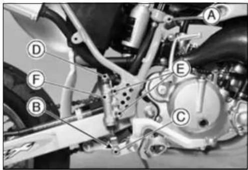
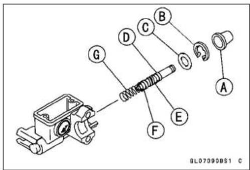
RearMasterCylinderDisassembly
- Removetherearmastercylinder.
- SlidethedustcoverAonthepushrod[B]outofplace, andremovetheretainer[C].
SpecialTool-InsideCirclipPliers:57001-143 - Pulloutthepushrodwiththepistonstop[D].
- Takeoffthepiston[E], primarycup[G], and returnspring [H].
NOTICE
Donotremovethesecondarycup[F]fromthepistonsinceremovalwilldamageit.
- Removethecirclip[I], and takeofftheconnector[J] and O-ring[K].

MasterCylinderAssembly
- Beforeassembly, cleanallpartsincludingthemaster cylinderwithbrakefluidoralcohol.
- Applybrakefluidtotheremovedpartsandtotheinner wallofthecylinder.
NOTICE
Exceptforthediscpadsanddisc,useonlydisc brakefluid,isopropylalcohol,orethylalcoholfor cleaningbrakeparts.Donotuseanyotherfluidfor cleaningtheseparts.Gasoline,engineoil,orany otherpetroleumdistillatewillcausedeteriorationof therubberparts.Oilspilledonanypartwillbedifficulttowashoffcompletely,andwilleventuallydeterioratetherubberusedinthediscbrake.
- Takecarenottoscratchthepistonortheinnerwallofthe cylinder.
- Tighten the brake lever pivot bolt and the locknut securely.
Torque-RearMasterCylinderPushRodLocknut:18N·m (1.8kgf·m,13ft·lb)
MasterCylinder
MasterCylinderInspection(VisualInspection)
- Disassemblethefrontandrearmastercylinders.
- Check that there are nos scratches, rust or pitting on the inner wallofeach master cylinder A and on the outside of each piston [B].
★Ifamastercylinderorpistonshowsanydamage,replace them. - Inspecttheprimary[C]andsecondary[D]cups.
★Ifacupisworn,damaged,softened(rotted),orswollen, thepistonassemblyshouldbereplacetorenewthecups.
★Iffluidleakageisnotedatthebrakelever,thepistonassemblyshouldbereplacedtorenewthecup. - Checkthedustcovers[E]fordamage.
★Iftheyaredamaged, replacethem. - Check that therelief[G] and supply[H] ports are not plugged.
★Ifthesmallreliefportbecomesplugged,thebrakepads willdragonthedisc.Blowtheportscleanwithcompressedair. - Checkthepistonreturnsprings[F]foranydamage.
★Ifaspringisdamaged,replaceit. [J]FrontMasterCylinder [K]RearMasterCylinder


BrakeDisk
BrakeDisclInspection
- VisuallyinspectthediscA.
★ Ifitisscratchedordamaged, replacethedisc. - Measurethethicknessofeachdiscatthepoint[B]where ithaswornthemost.
★Replacethediscifithaswornpasttheservicelimit.
Thickness
Standard:
Front2.80\~3.20mm
Rear2.80\~3.20mm
ServiceLimit:
Front2.5mm
Rear2.5mm
Torque-BrakeDiscMountingBolts:9.8N·m(1.0kgf·m,87in·lb)
- Placeajackunderthemotorcyclesothatthefront/rear wheelisraisedofftheground.
SpecialTool-Jack:57001-1238 - SetupadialgaugeagainstthediscAasillustrated.
○Forthefrontdisc,turnthehandlebarfullytooneside. - Measurethediscrunoutwhilerotatingthewheelslowly [B].
★ Iftherunoutexceedstheservicelimit,replacethedisc.
Runout
Standard: Notmorethan0.15mm
ServiceLimit:0.3mm


BrakeHose
BrakeHoseRemoval/Installation
NOTICE
Brakefluidquicklyruinspaintedorplasticsurfaces;anyspilledfluidshouldbecompletelywiped upimmediatelywithwateredcloth.
- When removing the brakehose, take care not to spill the brake fluid on the painted or plastic parts.
- When removing the brakehose, temporarily secure the endofthe brakehosetosome high placeto keep fluid lossto a minimum.
- Therearewashersoneachsideofthebrakehosefitting. Replacethemwithnewoneswheninstalling.
- Wheninstallingthehoses,avoidsharpbending,kinking, flatteningortwisting,androutethehosesaccording to theCable,WireandHoseRoutingsectionintheGeneral Informationchapter.
- Torquethebanjoboltsatthehosefittings.
Torque-BrakeHoseBanjoBolts:25N·m(2.5kgf·m,18 ft·lb)
- Bleedthebrakelineafterinstallingthebrakehose(see BleedingtheBrakeLine).
BrakeHoselnspection
- The high pressure insidethebrakeline can cause fluid to leak A or the host of burst theline is not properly maintained. Bend and twist the rubber hose while examining it.
★Replaceitifanycracks[B]orbulges[C]arenoticed
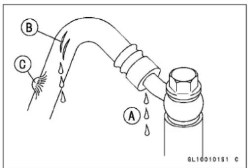
Suspension
TableofContents
Exploded View.... 11-2
Specifications 11-6
Front Fork 11-7
Rebound Damping Adjustment (KX65-A3 \~) 11-7
Fork Oil Level Adjustment (Simplify).... 11-7
OilChange/OilLevelAdjustment(eachforkleg)....11-9
Front Fork Removal 11-10
Front Fork Installation 11-11
Front Fork Disassembly (each fork).... 11-11
Front Fork Assembly (each fork).... 11-13
Inner Tube Inspection 11-14
Guide Bush Inspection.... 11-14
Dust Seal/Oil Seal Inspection 11-14
Spring Tension Inspection.... 11-14
Rear Suspension (Uni-Trak) 11-15
Rear Shock Absorber 11-15
ReboundDampingForceAdjustment....11-15
Spring Preload Adjustment 11-15
Rear Shock Absorber Removal 11-16
Rear Shock Absorber Installation 11-17
Spring Replacement 11-17
Spring Tension 11-18
Rear Shock Absorber Scrapping 11-18
Swingarm.... 11-19
Swingarm Removal 11-19
Swingarm Installation.... 11-19
Swingarm Bearing Removal 11-19
Swingarm Bearing Installation 11-20
Tie-rod, Rocker Arm 11-21
Tie-rod Removal 11-21
Tie-rod Installation 11-21
Rocker Arm Removal.... 11-21
Rocker Arm Installation.... 11-22
Needle Bearing Inspection.... 11-22
Uni-Trak Maintenance 11-23
Rocker Arm Sleeve Wear Inspection 11-23
Rocker Arm Mounting Bolt Bend Inspection 11-23
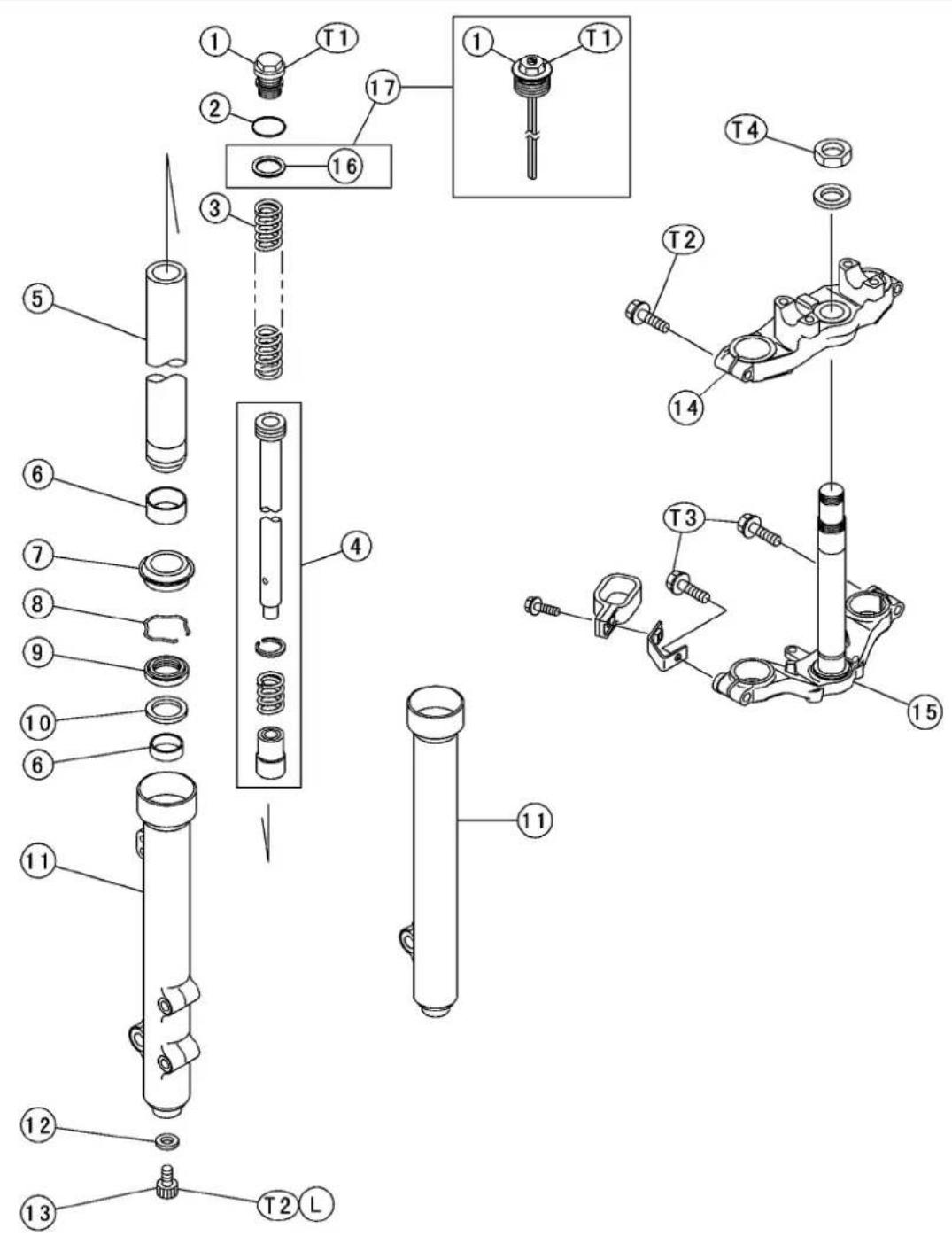
GM02006BW4 C
ExplodedView
1.TopPlug
2.O-ring
3.ForkSpring
4. Piston Cylinder Unit
5. InnerTube
6.GuideBushes
7.DustSeal
8.RetainingRing
9.OilSeal
10.Washer
11. OuterTube
12.Gasket
13. AllenBolt
14. SteeringStemHead
15. SteeringStem
16.SpringSeat
17.KX65-A3\~
T1:22N·m(2.2kgf·m,16ft·lb)
T2:20N·m(2.0kgf·m,14ft·lb)
T3:29N·m(3.0kgf·m,22ft·lb)
T4:44N·m(4.5kgf·m,33ft·lb)
L: Applyanon-permanentlockingagent.
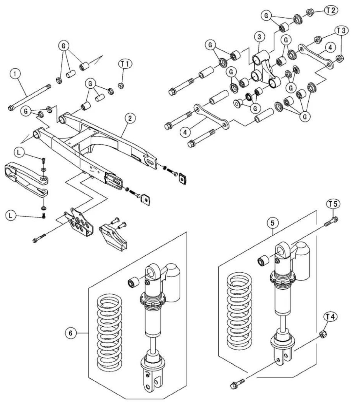
ExplodedView
1.PivotShaft
2.Swingarm
3.RockerArm
4. Tie-rod
5. RearShockAbsorber
6.RearShockAbsorber(KX65-A3\~)
T1:69N·m(7.0kgf·m,51ft·lb)
T2:83N·m(8.5kgf·m,61ft·lb)
T3:59N·m(6.0kgf·m,43ft·lb)
T4:34N·m(3.5kgf·m,25ft·lb)
T5:39N·m(4.0kgf·m,29ft·lb)
G:Applygrease.
L: Applyanon-permanentlockingagent.
Specifications
| Item | StandardServiceLimit | |
| FrontFork | ||
| OilViscositySHOWASS-8orequivalent- - - OilCapacity(CompletelyDry)238±2.5mL(KX65-A1)- - - OilLevel(FullyCompressed, SpringRemoved) | 240±2.5mL(KX65-A2) | - - - |
| 252±2.5mL(KX65-A3~) | - - - | |
| 124±2mm(KX65-A1) (fromtopofinnertube) | 98~ 140mm(KX65-A1) | |
| 126±2mm(KX65-A2) (fromtopofinnertube) | 96~ 139mm(KX65-A2) | |
| 132±2mm(KX65-A3~) (fromtopofinnertube) | 98 ~ 142 mm (KX65-A3 ~) | |
| ForkSpringFreeLength455.7mm(KX65-A1)446.6mm(KX65-A1) | 470.7mm(KX65-A2)461.3mm(KX65-A2) | 487.2 mm (KX65-A3 ~) |
| 497.1 mm (KX65-A3 ~) | ||
| RearSuspension(Uni-Trak) | ||
| RearShockAbsorber(AdjustableRange) | ||
| Spring Preload Adjustment | 88.8 mm (KX65-A1) | 82.8 ~ 94.8 mm (KX65-A1 ~ A2) |
| (Adjustingnutpositionfromthe 866.6mm(KX65-A2) center of the upper mounting hole) | 79.6 mm (KX65-A3 ~ A6) | 75.6 ~ 83.6 mm (KX65-A3 ~ A6) |
| 80.1 mm (KX65A6F ~) | 76.1 ~ 84.1 mm (KX65A6F ~) | |
| Rear Shock Spring Free Length | 206.1 mm | 202.0 mm |
| 211.1 mm (KX65-A3 ~) | 206.9 mm (KX65-A3 ~) | |
| GasReservoir | ||
| GasPressure | 980kPa(10kgf/cm2,142psi) | - - - |
| Tie-rod,RockerArm | ||
| Sleeve Outside Diameter | 17.989 ~ 18.000 mm | 17.96 mm |
| Rocker Arm Mounting Bolt Runout | under 0.1 mm | 0.2 mm |
Special Tools - Fork Cylinder Holder Handle: 57001-183
ForkCylinderHolderAdapter: 57001-1011
OilSeal&BearingRemover:57001-1058
HookWrench:57001-1101
BearingDriverSet:57001-1129
ForkOuterTubeWeight: 57001-1218
ForkOilSealDriver:57001-1219
Jack: 57001-1238
ForkOilLevelGauge:57001-1290
FrontFork
Thefrontforkshouldalwaysbeadjustedfortherider's weightandtrackconditionsbyusingoneormoreofthe followingmethods.
Oilleveladjustment-Theeffectsofhigherorlowerfork oillevelareonlyfeltduringthefinal100mmofforktravel. Ahigheroillevel(moreoil)willmaketheforkrepulsion morelarge.Aloweroillevel(lessoil)willmakethefork repulsionmoresmall.
OForksprings-Optionalspringsareavailablethatare softerandstifferthanstandard.
○Forkclampposition-Steeringqualitiesaregreatlyaffectedbytheforkclampposition.Forktubeheightis theamountoftheinnertubeprojectingabovethesteeringstemhead.Whenthefortubeheightissmaller,the frontendbecomeslighterduetothechangeinweight bias.Also,ittendstoundersteerinturnsand"washout". Whentheheightisgreater,theresultsareopposite.
ReboundDampingAdjustment(KX65-A3 \~)
- Toadjustrebounddamping,turntheadjusterAonthe frontforktopplugswiththebladeofascrewdriveruntil youfeelaclick.Adjusttherebounddampingtosuityou preferenceunderspecialcondition.
NOTICE
Theleftandrightforklegsmusthavethesame shockdamping.
Seatedpositions: adjuster turned fully clockwiseA.
ReboundDampingAdjusterSetting
Standard: 3 clicks
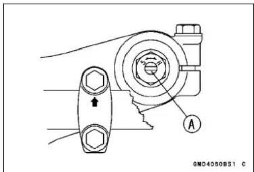

flowchart
graph LR
    A["Harder"] --> B{STD}
    B --> C["4"]
    B --> D["3"]
    B --> E["2"]
    B --> F["1"]
    G["Softer"] --> H["(Clockwise)"]
    H --> I["(Counterclockwise)"]
    I --> J["A"]
ForkOilLevelAdjustment(Simplify)
- Raisethefrontwheeloffthegroundusingajack.
SpecialTool-Jack:57001-1238 - Removethenumberplate.
- Remove the front fork top plugs A and the fork spring [B].

FrontFork
KX65-A3\~
- Remove:
NumberPlate
HandlebarAssembly
FrontForkTopPlugA
ForkSpring[B]
ForkSpringSeat[C]
- Slowlycompress the front fork fully bypassing up the outertubes A using a jack or others suitable means under the front wheel.
- Placeastandorothersuitablesupport[B]underthefront wheel.
- Usetheoillevelgaugetomeasuretheforkoillevel.
With the fork fully compressed, put the oil level gauge A and the stopper [B], and adjusted distance from the top of the inertubetool.
SpecialTool-ForkOilLevelGauge:570 01-1290
FrontForkOilLevel(ful lycompressed, withoutspring) Standard: 124±2mm(KX65-A1)
126±2mm(KX65-A2)
132±2mm(KX65-A3\~)
AdjustableRange: 98\~140mm(KX65-A1)
96\~139mm(KX65-A2)
98\~142mm(KX65-A 3\~)
★ Ifnooilisdrawnout, thereisinsufficientoilinthefork tube. Pourinenoughoil, thenpumpouttheexcessoil.
ForkOil:
SHOWASS-8orequivalent
- Measurethebothdiametersoftheforkspringendsand inserttheforkspringwiththesmalldiameterendAfacingdown.


natural_image
Mechanical assembly diagram showing a wheel mounted on a platform with labeled parts A and B (no text or symbols beyond labels)

natural_image
Diagram of a coiled spring with a rectangular base and labeled point A (no text or symbols beyond label)FrontFork
- CheckbothtopplugO-ringAfordamageandreplace themifnecessary.

natural_image
Close-up of a mechanical assembly with labeled component A (no readable text or symbols)• Installtheforktopplug.
• Installtheforktopplugandforspringseat(KX65-A3\~).
- Tightentheforktopplug.
Torque-FrontForkTopPlug:22N·m(2.2kgf·m,16ft·lb)
- Assembletheotherforktubeinthesamewayasdescribedabove.
• Installthepartsremoved.
- Installthehandlebarassembly(seeSteering).: KX65-A3\~
OilChange/OilLevelAdjustment(eachforkleg)
- Removethefrontfork(seethischapter).
- Removethefollowing. TopPlug
ForkSpring
ForkSpringSeat(KX65-A3\~)
WARNING
Thetopplugsareunderextremespringpressure andmayejectwithgreatforceduringservice.Use carewhenremovingthetopplugs.Weareyeand faceprotection.
- Holdtheforktubeupsidedownoveracleancontainer andpumpittodraintheoil.
- Fillthefrontforktothetopwithspecifiedoil.
RecommendedOil SHOWASS-8orequivalent
FrontForkOilCapacity(completelydry) 238±2.5mL(KX65-A1) 240±2.5mL(KX65-A2) 252±2.5mL(KX65-A3\~)
FrontFork
- Adjusttheoillevel.
With the fork fully compressed, put the oil level gauge A and the stopper [B], and inspect the distance from the top of the inertubeto the oil.
SpecialTool-ForkOilLevelGauge:57001-1290
OilLevel(fullycompressed, withoutspring) Standard: 124±2mm(KX65-A1)
126±2mm(KX65-A2)
132±2mm(KX65-A3\~)
AdjustableRange: 98\~140mm(KX65-A1)
96\~139mm(KX65-A2)
98 \~ 142 mm (KX65-A3 \~)
★ Ifnooilisdrawnout, thereisinsufficientoilinthefork tube. Pourinenoughoil, thendrawnouttheexcessoil.
- Installthepartsr emoved(seeFrontForkAssembly)

FrontForkRemoval
- RemovethefrontbrakehoseclampsA.
- Removethecaliper[B]fromtheforklegtoberemoved, andrestthecaliperonsomekindofstandsothatitdoesn't dangle.
- Removethefrontwheel(seeWheels/Tireschapter).

natural_image
Close-up of a bicycle wheel with visible tire, disc, and head assembly (no text or symbols)- Removethenumberplate.
- LoosentheupperandlowerforkclampboltsA.
- Withatwistingmotion,worktheforklegdownandout.
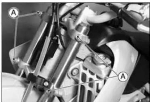
natural_image
Mechanical assembly diagram showing linkage components and labeled parts (A), no readable text or symbols present.FrontFork
FrontForkInstallation
- Iftheforklegwasdisassembled, checktheforkoillevel.
- InstalltheforksothatthetopendAoftheinnertubeis 10mmup[B]withtheuppersurface[C]ofthesteering stemhead.
- InstalltheforksothatthetopendAoftheinnertubeis 20mmup[B]withtheuppersurface[C]ofthesteering stemhead(KX65-A3\~).
- RoutethecablesandhoseaccordingtotheCable, Wire and HoseRoutingsectionintheGeneralInformation chapter.
• Installthefrontwheel(seeWheels/Tireschapter). - Tightenthefollowing:
Torque-FrontForkClampBolts(Upper):20N·m(2.0 kgf·m,14ft·lb) FrontForkClampBolts(Lower):29N·m(3.0 kgf·m,22ft·lb) CaliperMountingBolts:25N·m(2.5kgf·m,18ft·lb)
- Checkthefrontbrakeoperationafterinstallation.
FrontForkDisassembly(eachfork)
- Removethefrontfork(seethischapter).
- Removethetopplugandtheforkspring.
- Draintheforkoilwiththeforkupsidedown(seeForkOil Change)
- HoldtheoutertubeAinavise.
- Stopthecylinder[B]fromturningbyusingthefrontfork cylinderholder.
SpecialTools-ForkCylinderHolderHandle:57001-183[C] ForkCylinderHolderAdapter:57001-1011[D]
- UnscrewtheAllenbolt[E], thentaketheboltandgasket outofthebottomoftheoutertube.
KX65-A3\~
- Loosenthetopplug.
- Removethefrontfork(seethischapter).
- HoldtheoutertubeAinavise.
- Holdoftheinnertube[B]andloosentheAllenbolt[C].
- Removethetopplug, theforkspringseatandforspring (seeForkOilLevelAdjustment).
- Draintheforkoilwiththeforkupsidedown(seeForkOil Change)
• TakeouttheAllenbolt[C]andgasket.


11-12 SUSPENSION
FrontFork
- RemovethecylinderunitAandspring[B]fromthefork.
- RemovethedustsealAandretainingring[B].
- UsetheforkoutertubeweightAtoseparatetheinner tubefromtheoutertube. SpecialTool-ForkOuterTubeWeight:57001-1218
○ Holdingtheinnertubebyhandinaverticalposition,pull downtheoutertubeseveraltimestopullouttheinner tube.
- TheoilsealA, washer[B], and guidebushes[C] come off with the innertube. - Takethecylinderbase out of the outertube.

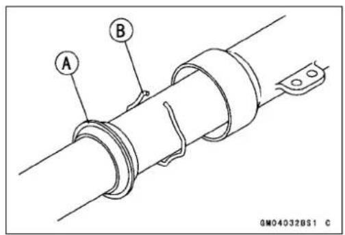

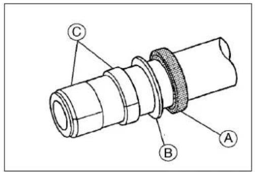
FrontFork
FrontForkAssembly(eachfork)
- Assemblyisthereverseofdisassembly.
- Replacethefollowingpartsremovedwithanewone.
GuideBushes
OilSeal
BottomAllenBoltGasket
- Inspect the following and replace them with new ones if damaged.
InnerTube(seeInnerTubeInspection)
TopPlugO-ring
- Insertthecylinderunitandspringintheinnertube.
- InsertthecylinderbaseAinthecylinderunit[B].
○Thecylinderbasemustbeinstalledwiththetaperedside facingupward.
- Installthecylinderunitintheinnertubeandthecylinder baseinthebottomoftheoutertube.
- Applyanon-permanentlockingagenttothebottomAllen boltandtightenittothespecifiedtorque,usingthefront forkcylinderholder.
Torque-ForkBottomAllenBolts:20N·m(2.0kgf·m,14ft·lb)
SpecialTools-ForkCylinderHolderHandle:57001-183
(use for KX65-A1 \~ A2)
ForkCylinderHolderAdapter: 57001-1011
(use for KX65-A1 \~ A2)
- InstalltheguidebushAbytapping[C]theusedguidebushwiththeforkoilseal driver[D]untilitstops.
SpecialTool-ForkOilSealDriver:57001-1219
-
Installthefollowing.
Washer
OilSeal(usetheforkoilsealdriver:57001-1219,the markedsideupward)
RetainingRing
DustSeal -
Measurethebothdiametersoftheforkspringendsand inserttheforkspringwiththesmalldiameterAfacing down.
- Pourtheforkoil(seeForkOilchange).
- Installthefrontfork(seeFrontForkInstallation).
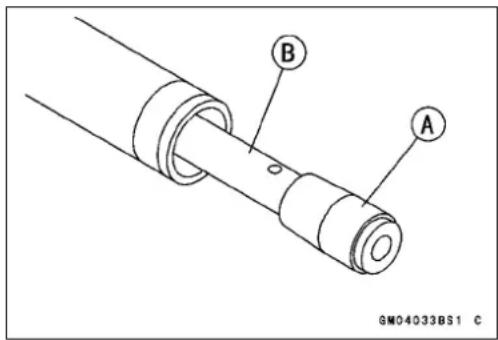


natural_image
Diagram of a coiled spring with labeled point A, no text or symbols presentFrontFork
InnerTubeInspection
- VisuallyinspecttheinnertubeA,repairanydamage.
- Nickorrustdamagecansometimesberepairedbyusing awet-stonetoremovesharpedgesorraisedareaswhich causesealdamage.
★ Ifthedamageisnotrepairable,replacetheinnertube. Sincedamagetotheinnertubedamagestheoilseal, replacetheoilsealwhenevertheinnertubeisrepaired orreplaced. - Temporarily assemble the inner and outer tubes, and pump them back and forth manually to check for smooth operation.
NOTICE
Iftheinnertubeisbadlybentorcreased,replace it.Excessivebending,followedbysubsequent straightening,canweakentheinnertube.
GuideBushInspection
- VisuallyinspecttheguidebushesA, andreplacethemif necessary.
DustSeal/OilSealInspection
- InspectthedustsealAforanysignsofdeteriorationor damage.
★Replaceitifnecessary. - Replacetheoilseal[B]withanewonewheneverithas beenremoved.
SpringTensionInspection
- Sinceaspringbecomesshorterasitweakens,checkits freelengthAtodetermineitcondition.
★ Ifthespringofeitherforklegisshorterthantheservice limit, itmustbereplaced. Ifthelengthofareplacement springandthatoftheremainingspringvarygreatly, the remainingspringshouldalsobereplacedinordertokeep theforklegsbalancedfromotorcyclestability.
ForkSpringFreeLength
Standard:455.7mm(KX65-A1)
470.7mm(KX65-A2)
497.1mm(KX65-A3\~)
ServiceLimit: 446.6mm(KX65-A1)
461.3mm(KX65-A2)
487.2mm(KX65-A3\~)

natural_image
Simple line drawing of a vertical cylindrical object with a labeled point A (no text or symbols beyond the label)

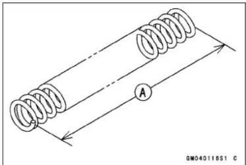
natural_image
Diagram of a coiled spring with labeled point A and reference number GM040118S1 C (no text or symbols on the diagram itself)RearSuspension(Uni-Trak)
RearShockAbsorber
TherearsuspensionsystemofthismotorcycleisUni-trak. Itconsistsofarearshockabsorber,swingarm,tie-rodand rockerarm.
Tosuittovariousridingconditions,thespringpreloadof theshockabsorbercanbeadjustedorthespringcanbe replacedwithanoptionalone.
KX65-A3\~
Thedampingforce can be adjusted easily so changing oil viscosity unnecessary.
ReboundDampingForceAdjustment
- Toadjusttherebounddampingforce,turnthelower dampingadjusterApunchmark[B].
★Ifthedampingfeelstoosoftortoostiff,adjustit.
Seatedposition:adjustertunedfullyclockwiseA
ReboundDampingAdjusterSetting Standard:11/2turnsout
○Differtheindividuallyforshockabsorbersideofthepunch markposition[B].


flowchart
graph TD
    A["(Counterclockwise) Softer"] --> B["1 1/2 STD"]
    C["(Clockwise) Harder"] --> D["3 Adjustable range"]
    B --> E["B"]
    D --> F["A"]
    style A fill:#f9f,stroke:#333
    style C fill:#f9f,stroke:#333
    style B fill:#ccf,stroke:#333
    style D fill:#ccf,stroke:#333
SpringPreloadAdjustment
- Remove:
Seat
SideCovers
RearFrameA
AirCleanerHousing[B]
- Usingthejackundertheframe,raisetherearwheeloff theground.
SpecialTool-Jack:57001-1238
- Using the hook wrenchesA, loosenthelocknut[B] on therearshockabsorber.
SpecialTool-HookWrench:57001-1101

natural_image
Close-up of a mechanical assembly with labeled parts A and B, showing no readable text or symbols beyond labels.
11-16 SUSPENSION
RearSuspension(Uni-Trak)
- UsingthehookwrenchA,turntheadjustingnut[B]as required.Turningtheadjustingnutdownwardmarksthe springactionharderandupwardsofter.
SpecialTool-HookWrench:57001-1101

natural_image
Close-up of a mechanical assembly with labeled parts A and B, showing hands adjusting components (no readable text or symbols)SpringPreloadAdjustment
(AdjustingnutpositionAfromthecenter ofthemountinghole)
Standard:88.8mm(KX65-A1)
86.6mm(KX65-A2)
79.6mm(KX65-A3\~A6)
80.1mm(KX65A6F\~)
AdjustableRange:
82.8 \~ 94.8 mm (KX65-A1 \~ A2)
75.6 \~ 83.6 mm (KX65-A3 \~ A6)
76.1 \~ 84.1 mm (KX65A6F \~)

- Tightenthelocknutsecurely.
- Afteradjusting, movethespringupanddowntomake surethatthespringisseated.
• Installthepartsremoved. - Tightentherearframemountingbolts.
Torque-RearFrameMountingBolts:34N·m(3.5kgf·m25ft·lb)
RearShockAbsorberRemoval
- Remove:
Seat
SideCovers
RearFrame
AirCleanerHousing
- Usingthejackundertheframe,raisetherearwheeloff theground.
SpecialTool-Jack:57001-1238
- Removethetie-rodfrontmountingboltA.
NOTICE
When pulling out them mounting bolts, lift therear wheels slightly. Forcingortappingonabolt could damagethebolt, sleeve, and bearing
- RemovetherearshockabsorbermountingboltB].

RearSuspension(Uni-Trak)
- RemovetherearshockabsorberuppermountingboltA, andpullouttherearshockabsorber[B].
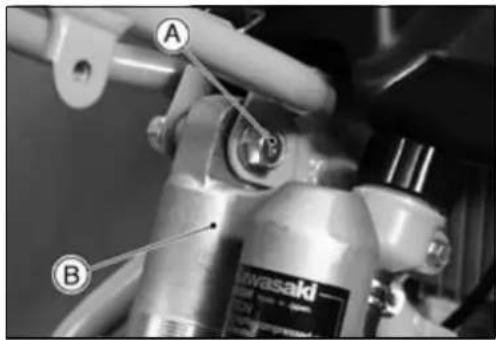
RearShockAbsorberInstallation
- Packtherockerarmneedlebearingswithgrease.
- Tightenthefollowing:
Torque-RearShockAbsorberMountingBolt(Upper):39 N·m(4.0kgf·m,29ft·lb)
RearShockAbsorberMountingNut(Lower):34 N·m(3.5kgf·m,25ft·lb)
Tie-rodMountingNut:59N·m(6.0kgf·m,43ft·lb)
RearFrameMountingBolts:34N·m(3.5kgf·m,25ft·lb)
SpringReplacement
Inadditiontothestandardspring,heavyandlightsprings areavailable.Ifthestandardspringisimproperforyour purpose,selectaproperoneaccordingtotherider'sweight orcourseconditions.
- Remove
SideCovers
Seat
RearFrame
AirCleanerHousing
- Removetherearshockabsorber.
- Cleanethreadedportionontheupperoftherearshock absorber.
- Holdtheloweroftherearshockabsorberwithavise.
- Using the hookwrenches[C], loosenthelocknut[B] and turnthead adjusting nutA all wayup.
SpecialTool- HookWrench:57001-1101

11-18 SUSPENSION
RearSuspension(Uni-Trak)
- Removetherearshockabsorberfromthevise.
- RemovethestopperringA.
- Removethespringseat[B]fromtheshockabsorberand liftoffthespring[C].
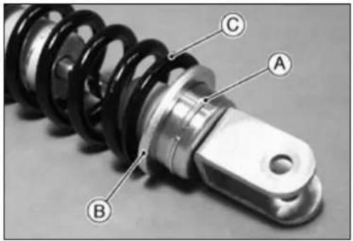
• Installthespringguide.
- Adjust the spring preload (see Spring Preload Adjustment).
• Installtherearshockabsorber.
• Installthepartsremoved.
SpringTension
Sinceaspringbecomesshorterasitweakens,checkits freelengthAtodetermineitscondition.
★ Ifthespringisshorterthantheservicelimit, it must be replaced.
RearShockAbsorberSpringFreeLength
Standard:206.1mm(KX65-A1\~A2)
211.1mm(KX65-A3\~)
ServiceLimit:202.0mm(KX65-A1\~A2)
206.9mm(KX65-A3\~)
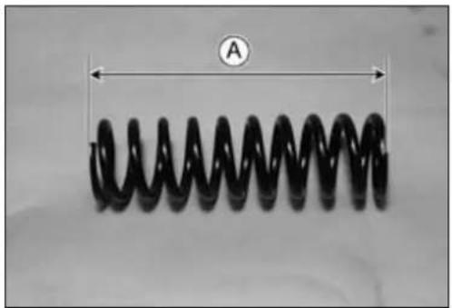
natural_image
Close-up of a black helical spring with diameter labeled 'A' (no text or symbols on the spring itself)RearShockAbsorbe rScrapping
WARNING
Sincethereserv oirtankoftherearshockabsorber containsnitrogengas, donotincineratethereserv-voirtankwithoutfirstreleasingthegasoritmay explode.
- Removetheshockabsorber(seeRearShockAbsorber Removal).
- RemovethevalvecapAandreleasethenitrogengas completelyfromthegasreservoir.
- Removethevalve.
WARNING
Pressurizedgascancauseinjury.Donotpointthe valvetowardyourfaceorbody.

natural_image
Technical line drawing of a mechanical assembly with cylindrical components and a labeled component (no text or symbols present)Swingarm
SwingarmRemoval
- Placethejackundertheframesothattherearwheelis offtheground.
SpecialTool-Jack:57001-1238
- Removetherearwheel(seeWheels/Tireschapter).
- RemovethebrakepedalA.
- Removethetie-rodrearmountingbolt[B].
NOTICE
When pulling out them mounting bolts, lift therear wheels slightly. Forcingortappingonabolt could damagethebolt, sleeve, and bearing.
- Pullouttheswingarmpivotshaft[C], andremovethe swingarm[D].
- Separatethechainguideandchainslipperfromthe swingarm.
SwingarmInstallation
- Applyplentyofgreasetotheinsideoftheneedlebearings, sleeves, and oilsealscaps.
- Tightenthefollowing:
Torque-SwingarmPivotShaftNut:69N·m(7.0kgf·m,51ft·lb)
Tie-rodMountingNut:59N·m(6.0kgf·m,43ft·lb)
- RefertotheWheels/Tires, FinalDrive, and Brakeschapters for wheel installing.
SwingarmBearingRemoval
- Remove:
Swingarm
DustSealsA
OilSeals[B]
Sleeves[C]
- Removetheneedlebearings[D]usingthebearingremover.
SpecialTool-OilSeal&BearingRemover:57001-1058


Swingarm
SwingarmBearingInstallation
- Replacetheneedlebearings, dustsealsandoilsealswith newones.
- Applyplentyofgreasetothedustseals, oilsealsand needlebearings.
NOTE
○Installtheneedlebearingssothatthemanufacturer's marksfaceout.
SpecialTool-BearingDriverSet:57001-1129
- InstalltheneedlebearingsAdustseals[B]andoilseals[C]positionasshown.
○ Theinstallationprocedureisthesameasthecounter side.

Tie-rod,RockerArm
Tie-rodRemoval
- Usingthejackundertheframe,raisetherearwheeloff theground.
SpecialTool-Jack:57001-1238
- Removethetie-rodfrontmountingboltA.
NOTICE
When pulling out them mounting bolts, lift therear wheels slightly. Forcingortappingonabolt could damagethebolt, sleeve, and bearing.
- Removethetie-rodrearmountingbolt[B], andthentake outthetie-rods[C].
Tie-rodInstallation
- Applyplentyofgreasetotheinsideoftheneedlebearings andoilseals.
- Tightenthetie-rodfrontandrearmountingnuts.
Torque-Tie-rodMountingNuts:59N·m(6.0kgf·m,43ft·lb)
RockerArmRemoval
- Usingthejackundertheframe,raisetherearwheeloff theground.
SpecialTool-Jack:57001-1238
- RemovethechainAandthelowerchainguideroller[B].
- Removethetie-rodfrontmountingboltA.
NOTICE
When pulling out them mounting bolts, lift therear wheels slightly. Forcingortappingon bolt could damage the bolt, sleeve, and bearing.
- Removetherearshockabsorberlowermountingbolt[B].
- Removetherockerarmpivotshaft[C].
- Removetherockerarm[D].
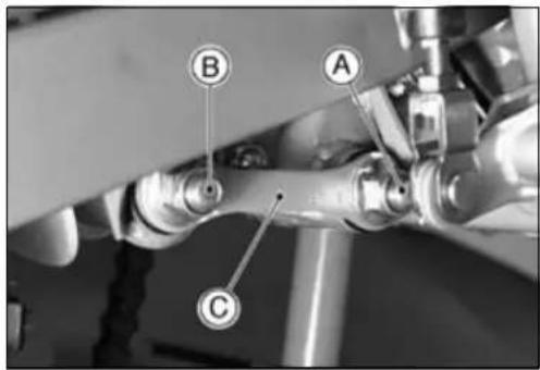

natural_image
Mechanical assembly diagram showing a chain link and labeled components A and B (no text or symbols beyond labels)
11-22 SUSPENSION
Tie-rod,RockerArm
RockerArmInstallation
- Applyplentyofgreasetotheinsideoftherockerarm holes, needlebearings, oilsealsandgreasesealsoutsideofthesleeve.
- InstalltheneedlebearingA,greaseseals[B]andoil seals[C]positionasshown.
- Tightenthefollowing:
Torque-RockerArmPivotNut:83N·m(8.5kgf·m,61ft·lb)
RearShockAbsorberMountingNut(Lower):34 N·m(3.5kgf·m,25ft·lb)
Tie-rodMountingNuts:59N·m(6.0kgf·m,43ft·lb)
SwingarmPivotShaftNut:69N·m(7.0kgf·m,51ft·lb)
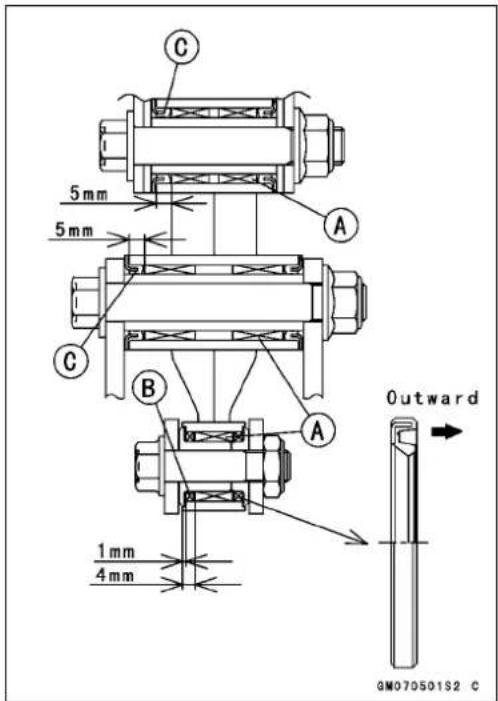
NeedleBearingInspection
★ Ifthereisanydoubtastotheconditionofeitherneedle bearing,replacethebearingandsleeveasaset.
Uni-TrakMaintenance
Checktheuni-trakcomponentpartsforwearperiodically, orwheneverexcessiveplayissuspected.
- Usingthejackundertheframe,raisetherearwheeloff theground.
SpecialTool-Jack:57001-1238
- PushandpullontheswingarmA, upanddown, tocheck forwear.
★Asmallamountofplayontheswingarmisnormalandno correctiveactionisneeded.However,ifexcessiveplayis felt,removetheuni-trakpartsfromtheframeandcheck forwear.
RockerArmSleeveWearInspection
- PulloutthesleevesAoftherockerarm,andmeasure theoutsidediameterofthesleeve.
★ Ifthesleeveiswornpasttheservicelimit,replacethe sleeve.
SleeveOutsideDiameter
Standard: 17.989\~18.000mm
ServiceLimit: 17.96mm

natural_image
Close-up of a hand adjusting a bicycle wheel rim with labeled components (no readable text or symbols)
natural_image
Mechanical assembly with a metallic valve and multiple small components (no visible text or symbols)RockerArmMountingBoltBendInspection
Abentboltcausesvibration,poorhandling,andinstability.
- Tomeasuretheboltrunout,removethebolt,placeit inVblock,andsetadialgaugetotheboltatapoint halfwaybetweenheblock.TurnAthebolttomeasure therunout.Theamountofdialvariationistheamountof runout.
★ Ifrunoutexceedstheservicelimit, replacethebolt.
BoltRunout
Standard: Under0.1mm
ServiceLimit: 0.2mm

Steering
TableofContents
Exploded View 12-2
Specifications 12-3
Steering 12-4
Steering Inspection 12-4
Steering Adjustment.... 12-4
SteeringStem,StemBearingRemoval....12-5
SteeringStem,StemBearingInstallation....12-6
Steering Maintenance.... 12-8
Stem Bearing Lubrication.... 12-8
StemBearingWear, DamageInspection....12-8
Stem Warp Inspection.... 12-8
Handlebar 12-9
Handlebar Removal 12-9
Handlebar Installation 12-9
Clutch Lever Installation.... 12-9
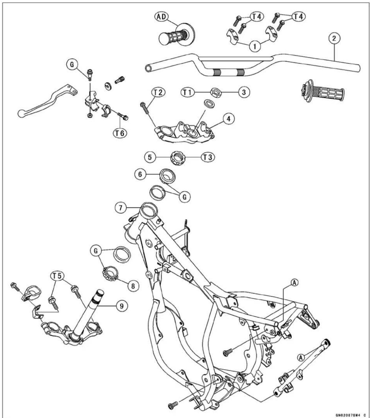
- HandlebarClamp
- Handlebar
- SteeringStemHeadNut
- SteeringStemHeadBracket
- SteeringStemNut
6.TaperedRollerBearing
7.HeadPipe
8.TaperedRollerBearing - SteeringStem
T3:2.9N·m(0.30kgf·m,26in·lb)
T4:25N·m(2.5kgf·m,18ft·lb)
T5:29N·m(3.0kgf·m,22ft·lb)
T6:8.8N·m(0.90kgf·m,78in·lb)
AD:Applyadhesivecement.
G:Applygrease.
Specifications
SpecialTools-SteeringStemBearingDriver:57001-137
HeadPipeOuterRacePressShaft:57001-1075
SteeringStemBearingDriverAdapter:57001-1092
SteeringStemNutWrench:57001-1100
HeadPipeOuterRaceDriver:57001-1106
HeadPipeOuterRaceRemover:57001-1107
Jack:57001-1238
Steering
SteeringInspection
- Usingthejack,raisethefrontwheelofftheground.
SpecialTool-Jack:57001-1238 - Withthefrontwheelpointingstraightahead, alternately nudgeeachendofthehandlebar. Thefrontwheelshould swingfullyleftandrightfromtheforceofgravityuntilthe forkhitsthestop.
★ If the steering binds or catches before the stop, check the routing of the cables, hoses, and harnesses.
★ Ifthesteeringfeelstight, adjustorlubricatethesteering. - Feelforsteeringloosenessbypushingandpullingthe forks.
★ Ifyoufeellooseness,adjustthesteering.
SteeringAdjustment
- Removethenumberplate.
- Usingthejack,raisethefrontwheelofftheground.
SpecialTool-Jack:57001-1238 - Removethehandlebar.
- LoosenthefrontforkclampboltsAandsteeringstem headnut[B].

natural_image
Close-up of hands adjusting a bicycle wheel rim and tire assembly (no visible text or symbols)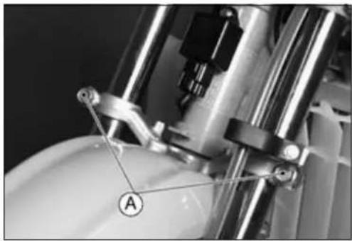
natural_image
Close-up of mechanical components with no visible text or symbols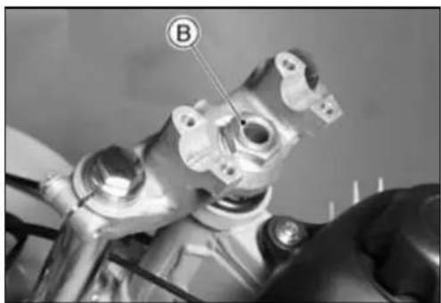
natural_image
Close-up of a mechanical component with labeled point B (no readable text or symbols)
- TurnthesteeringstemnutAwiththesteeringstemnut wrench[B]toobtaintheproperadjustment.
★ Ifthesteeringistootight, loosenthesteeringstemnuta fractionofaturn; ifthesteeringistooloose, tightenthe nutafractionofaturn.
SpecialTool-SteeringStemNutWrench:57001-1100
NOTE
○Turnthesteeringstemnut1/8turnatatimemaximum.
- Tightenthefollowing:
Torque-Steering Stem Head Nut: 44N·m (4.5kgf·m, 33ft·lb)
Front Fork Clamp Bolts (Lower): 29 N·m (3.0 kgf·m,22ft·lb)
Steering
SteeringStem, StemBearingRemoval
- Remove:
FrontWheel(seeWheels/Tireschapter) BrakeHoseClamp(seeBrakeSystemchapter) CaliperMountingBolts(seeBrakeSystemchapter) MasterCylinderClamp(seeBrakeSystemchapter) FrontFender Handlebar(seeHandlebarRemoval) FrontFork(seeSuspensionchapter)
- Removethesteeringstemheadnutandwasher.
- Removethesteeringstemhead.
- PushinguponthestembaseA,andremovethesteering stemnut[B],withthesteeringstemnutwrench[C],then removethesteeringstem[D].
SpecialTool-SteeringStemNutWrench:57001-1100
- Takeofftheupperstembearinginnerrace(taperedroller bearing)A.
- Driveoutthebearingouterracesfromtheheadpipe. ○Removetheouterracespressedintotheheadpipe,using theheadpipeouterraceremoverA,andhammerthe headpipeouterraceremovertodriveitout.
SpecialTool-HeadPipeOuterRaceRemover:57001 -1107
NOTE
○ Ifeithersteeringstem bearingisdamaged,itisrecommendedthatboththeupperandlowerbearing(includingouterraces)shouldbereplacedwithnewones.
- Removethelowerstembearinginnerrace(taperedroller bearing)Awithitsgreasesealfromthestemusingsuitabletools.
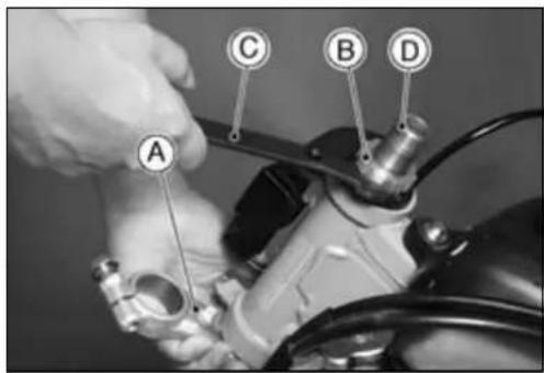


Steering
SteeringStem, StemBearingInstallation
- Replacethebearingouterracewithnewones.
○Applygreasetotheouterraces, and drivetheminto the headpipe using the pressshaftA and the drivers[B].
SpecialTools-HeadPipeOuterRacePressShaft:57001
-1075
HeadPipeOuterRaceDriver:57001-1106
- Replacethelowerinnerraceswithnewones.
○Applygreasetothelowerinnerrace, and drive it onto the stem using the steering stem bearing driverA and adapter[B].
SpecialTools-SteeringStemBearingDriver:57001-137
SteeringStemBearingDriverAdapter: 57001-1092
- Applygreasetotheupperinnerrace, and installitinthe headpipe.
- Installthestemthroughsteeringtheheadpipeandupperbearing,andhand-tightenthesteeringstemnutwhile pushinguponthestembase.
- Installthestemheadandwasher, andtightenthestem headnutlightly.
- Settlethebearinginplaceasfollows;
○ Tightenthesteeringstemnutto39N·m(4.0kgf·m,29ft·lb)oftorque.(Totightenthesteeringstemnuttothe specifiedtorque,hookthewrenchAonthesteeringstem nut,andpullthewrenchattheholeby22.2kgforce[B] inthedirectionshown.)
SpecialTooI - SteeringSt emNutWrench:57001-1100
○Checkthatthereisnoplayandthesteeringstemturns smoothlywithouttrattles.Ifnot,thesteeringstembearings maybedamaged.
○Againbackoutthesteeringstemnutafractionofaturn untilturnslightly.
Turnthesteeringstemnutlightlyclockwiseuntilitjust becomeshardtoturn.Donotovertighten,orthesteering willbetootight.
Torque- SteeringStemNut:2.9N·m(0.3kgf·m,26in·lb)
• Installthefrontfork(seetheSuspensionchapter).
NOTE
○Tightentheforkupperclampboltsfirst,nextthestem headnut,lasttheforklowerclampbolt.
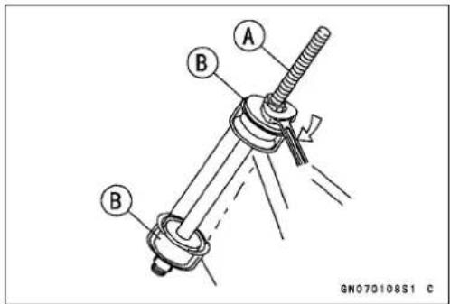


Steering
Torque-SteeringStemHeadNut:44N·m(4.5kgf·m,33ft·lb)
FrontForkClampBolt:
Upper:20N·m(2.0kgf·m,15ft·lb)
Lower:29N·m(3.0kgf·m,22ft·lb)
- Installthepartsremoved(seetheappropriatechapter).
WARNING
Donotimpedethehandlebarturningbyroutingthe cables,wiresandhosesimproperly(seetheGeneralInformationchapter).
- CheckandAdjust:
Steering
FrontBrake
ClutchCable
ThrottleCable
12-8STEERING
SteeringMaintenance
StemBearingLubrication
- Removethesteeringstem(seeSteeringStemRemoval).
- Usingahighflash-pointsolvent,washtheupperand lowertaperedrollersinthecages,andwipetheupper andlowerouterraces,whicharepress-fittedintothe frameheadpipe,cleanoffgreaseanddirt.
- Visuallychecktheouterracesandtherollers.
★Replacethebearingassembliesiftheyshowwearor damage. - PacktheupperandlowertaperedrollerbearingsAin thecageswithgrease,andapplyalightcoatofgreaseto theupperandlowerouterraces.
- Installthesteeringstem, and adjust thesteering (see SteeringStem, StemBearing Installation, Steering Adjustment).
StemBearingWear, DamageInspection
- Usingahighflash-pointsolvent,washtheupperand lowertaperedrollersinthecages,andwipetheupper andlowerouterraces,whicharepress-fittedintothe frameheadpipe,cleanoffgreaseanddirt.
- Visuallychecktheouterraseandtherollers.
★Replacethebearingassemblyifitshowdamage.
StemWarpInspection
- Whenever the steering stem is removed, or the steering cannot be adjusted for smooth action, check the steering stem for straightness.
★ If thesteeringstemshaft is bent A, replace thesteering stem.

natural_image
Mechanical component with labeled parts (A and a small circular feature), no readable text or symbols present.
natural_image
Technical line drawing of a mechanical assembly with labeled component A (no text or symbols beyond label)Handlebar
HandlebarRemoval
- Remove:
EngineStopButtonA
ClutchHolder[B]
ThrottleGripAssembly[C]
FrontMasterCylinder[D]
HandlebarHolders[E]
Handlebar[F]
HandlebarInstallation
- Applyadhesivecementtotheinsideofthelefthandlebar gripA.
-
Installthefrontmastercylinder(seeFrontMasterCylinder InstallationintheBrakeschapter).
-
Mountthehandlebarclamps[B]sothathearrows[C]on theclamppointatthefrontA.
- Alignthepunchmark[D]onthehandlebartothemating surfaceofeachclampsofhandlebar.
- Tightenthehandlebarclampbolts.
Torque-HandlebarClampBolts:25N·m(2.5kgf·m,18 ft·lb)
○Tightentheclampbolts,frontfirstandthentherear. If thehandlebarclampiscorrectlyinstalled,therewillbeno gapatthefrontandagap[E]attherearaftertightening.
ClutchLeverInstallation
- InstalltheclutchleversothatthematingsurfaceAofthe clutchleverclampisalignedwiththepunchmark[B].
Torque-ClutchLeverClampBolts:8.8N·m(0.90kgf·m,78in·lb)
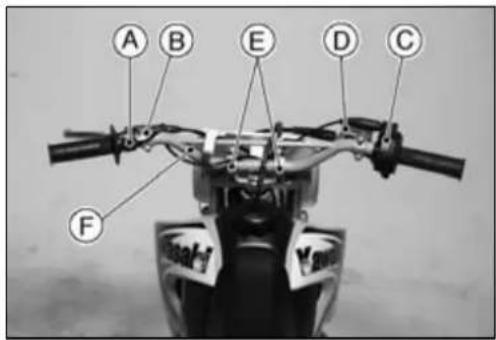

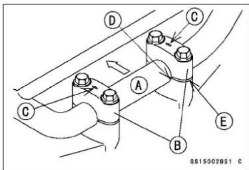

ElectricalSystem
TableofContents
Wiring Diagram.... 13-2
Exploded View.... 13-3
Specifications 13-4
Precautions.... 13-5
Electrical Wiring 13-6
Wiring Inspection 13-6
Ignition Timing 13-7
Ignition Timing Adjustment.... 13-7
Flywheel Magneto 13-8
Flywheel Magneto Removal.... 13-8
Flywheel Magneto Installation.... 13-8
Crankshaft Sensor Air Gap Inspection (KX65A6F \~) 13-9
Flywheel Magneto Inspection 13-9
Ignition System.... 13-11
Crankshaft Sensor Installation (KX65A6F \~) 13-11
Crankshaft Sensor Air Gap Adjustment (KX65A6F \~) 13-11
Crankshaft Sensor Inspection (KX65A6F \~) 13-11
Crankshaft Sensor Peak Voltage Inspection (KX65A6F \~) 13-12
Ignition Coil Removal 13-12
Ignition Coil Installation 13-12
Ignition Coil Inspection.... 13-12
Spark Plug Cleaning and Inspection.... 13-14
Spark Plug Gap Inspection 13-14
CDI Unit Removal 13-14
CDI Unit Inspection 13-14
13-2 ELECTRICAL SYSTEM
WiringDiagram

GP07016BW2 C
KX65A6F\~

flowchart
graph TD
    A["Magneto"] --> B["Crankshaft Sensor"]
    B --> C["CDI Unit"]
    C --> D["Ignition Coil"]
    D --> E["Engine Stop Button"]
    E --> F["Spark Plug Cap"]
    F --> G["Spark Plug"]
    G --> H["Ground"]
    style A fill:#f9f,stroke:#333
    style B fill:#ccf,stroke:#333
    style C fill:#cfc,stroke:#333
    style D fill:#fcc,stroke:#333
    style E fill:#ffc,stroke:#333
    style F fill:#cff,stroke:#333
    style G fill:#ffc,stroke:#333
    style H fill:#cfc,stroke:#333
    subgraph Color Code
        I["BK Black"]
        J["G Green"]
        K["O Orange"]
        L["R Red"]
        M["W White"]
        N["Y Yellow"]
    end
ExplodedView

1.MagnetoCover
2.MagnetoFlywheel
3. Stator
4.CDIUnit
5.IgnitionCoil
6.SparkPlugCap
7.SparkPlug
8. EngineStopButton
9.KX65-A1\~A6
T1:29N·m(3.0kgf·m,21ft·lb)
T2:4.9N·m(0.50kgf·m,43in·lb)
T3:25N·m(2.6kgf·m,19ft·lb)
T4:8.8N·m(0.90kgf·m,78in·lb)
SS:Applysiliconesealant.
GP022958W4 C
Specifications
| Item | Standard |
| MagnetoStatorcoilresistanceinthetext | |
| IgnitionSystemIgnitionTiming:IgnitionCoil:3NeedleArcingDistance7mmormorePrimary Winding ResistanceSecondaryWindingResistance3.1kΩ ±15%SparkPlug:TypeGap0.5~ 0.6mmCDI.unit:inthetext | 20.5°BTDC@6000r/min(rpm)20.5°BTDC@7100r/min(rpm)(KX65A6F~)0.31 Ω ±15% (at 20°C)(at20°C)NGKBR10EGNGKB10EG(KX65-A1~ A6(US)) |
SpecialTools-FlywheelPuller:57001-252
Flywheel&PulleyHolder:57001-1343
HandTeste:57001-1394
PeakVoltageAdapter:57001-1415
LiquidGasket, TB1211:56019-120
US:UnitedStatesModel
Precautions
Thereare numbers of important precaution that are must always servicing electrical systems. Learn and observe all the rules below.
○Theelectricalpartsshouldneverbestrucksharply,as withahammer,orallowedtofallonahardsurface.Such ashocktothepartscandamagethem.
○Troublesmayinvolveoneorinsomecasesallitems. Neverreplaceadefectivepartwithoutdeterminingwhat CAUSEDthefailure.Ifthefailurewascausedbysome otheritemoritems,theytoomustberepairedorreplaced, orthenewreplacementwillsoonfailagain.
○Makesureallconnectorsinthecircuitarecleanandtight, andexaminewiresforsignsofburning, fraying, etc. Poor wiresandbadconnectionswillaffectelectricalsystemoperation.
○Measurecoilandwindingresistancewhenthepartiscold (atroomtemperature).
SafetyInstructions

WARNING
Theignitionsystemproducesextremelyhighvoltage.Donottouchthesparkplug,ignitioncoilorignitioncoilleadwhiletheengineisrunning,oryou couldreceiveasevereelectricalshock.
13-6 ELECTRICAL SYSTEM
Electrical Wiring
WiringInspection
- Visuallyinspectthewiringforsignsofburning,fraying, etc.
★ Ifanywiringispoor, replacethedamagedwiring. - PulleachconnectorAapartandinspectitforcorrosion, dirt, and damage.
★ Iftheconnectoriscorrodedordirty, cleanitcarefully. Ifit isdamaged, replace it. - Checkthewiringforcontinuity.
○Usethewiringdiagramtofindtheendsoftheleadwhich issuspectedofbeingaproblem.
○Connectanohmmeterbetweentheendsoftheleads.
○Setthemetertothe×1Ω range, andleadthemeter.
★ Ifthemeterdoesnotread0Ω theleadisdefective. Re- placetheleadorthewiringharnessifnecessary.

natural_image
Pure electrical circuit lines without any symbolsIgnitionTiming
IgnitionTimingAdjustment
- Removethemagnetocover.
- ChecktoseeifthecentermarkofthethreemarksAon themagnetostatorplateisalignedwiththemark[B]on thecrankcase.
★Ifthemarksarenotaligned,loosenthemagnetostator platemountingscrews[C]andturnthestator[D]. - Tightenthestatorplatemountingscrewssecurely.
Torque-StatorPlateMountingScrews:4.9N·m(0.50 kgf·m,43in·lb)
• Installthemagnetocover.
Torque-MagnetoCoverBolts:8.8N·m(0.90kgf·m,78in·lb)
Theignitiontimingcanbeadjustedfordifferentpower bandtosuittorider'spreferenceability.
- Removethemagnetocover.
- Loosenthestatorplatemountingscrews.
- Adjustthetimingbyshiftingthestatorpositionwithinthe threelinesA.


natural_image
Technical line drawing of a mechanical assembly with bolted components and labeled section A (no readable text or symbols beyond labels)NOTE
○ Forbestengineperformance,itisveryimportanttoadjusttheignitiontimingwithintheadjustablerangejust explained.
ACrankshaftRotation
[B]Statorplateofmovement
[C]Advance
[D]Retard
- Tightenthestatorplatemountingscrews securely (see IgnitingTimingAdjustment).
• Installthemagnetocover. - Testridethemotorcycleandreadjusttheignitiontimingif necessary.

FlywheelMagneto
FlywheelMagnetoRemoval
- Removethemagnetocover.
-
Holdtheflywheelsteady, withtheflywheel&pulleyholder A, andremovetheflywheelnut[B].
SpecialTool-Flywheel&PulleyHolder:57001-1343 -
ScrewtheflywheelpullerAintotheflywheelbyturning itcounterclockwise(left-handthread).
- Removetheflywheelfromthecrankshaftbyturninginthe pullercenterboltandtappingtheheadoftheboltlightly withahammer,whileholdingthepullerbodysteady. Thereisawoodruffkeyinthecrankshafttaperedportion.
SpecialTool-FlywheelPuller:57001-252
NOTICE
Neverstrikethegrabbarortheflywheelitself. Strikethebarcanbondit.Iftheflywheelisstrike, themagnetsmaylosetheirmagnetism.
- Unscrewthemounti ngscrewsA,andremovethestator plate[B]andthewiringgrommet[C].
- Removetheband.
- Disconnectt hestatorleadconnectorsfromtheharness.


FlywheelMagnetolnstallation
• Installthestatorplate.
- Applysiliconesealantaroundthestatorwiringgrommet A, andsetitinthenotch[B] in the left crank case half securely, and routethe leads according to the Cable, Wire and Hose Routing section in the General Information chapter.
Torque-StatorPlateMountingScrews:4.9N·m(0.50 kgf·m,43in·lb)
Sealant-LiquidGasket, TB1211:56019-120
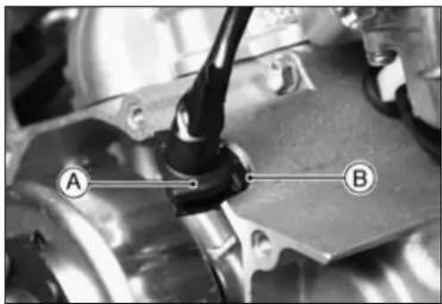
FlywheelMagneto
- Usingahighflash-pointsolvent,cleanoffanyoilordirt thatmaybeonthecrankshafttaperAorinthehole[B]intheflywheel.Drythemwithacleancloth.
- FitthewoodruffkeyAsecurelyintheslotinthecrank-shaftbeforeinstallingthestatorplate.
- Holdingtheflywheelsteady, withtheflywheelholderA, andtightentheflywheelnut[B].
SpecialTool-Flywheel&PulleyHolder:57001-1343
Torque-FlywheelNut:29N·m(3.0kgf·m,21ft·lb) MagnetoCoverBolts:8.8N·m(0.90kgf·m,78in·lb)


CrankshaftSensorAirGapInspection(KX65A6F \~)
- Removethemagnetocover.
- MeasurethecrankshaftsensorairgapA.
CrankshaftSensorAirGap
0.5±0.1mm(0.020±0.004in.)
★ Ifthegapisincorrect, reinstallthecrankshaftsensorso thatthegaphascorrectclearance.
FlywheelMagnetoInspection
- Therearethreetypesofmagnetoproblems:short,open (wireburnedout),orlossinflywheelmagnetism.Ashort oropeninoneofthecoilwireswillresultineitheralow output,ornooutputatall.Alossinflywheelmagnetism, whichmaybecausedbydroppingorhittingtheflywheel byleavingitnearanelectromagneticfield,orjustbyaging,willresultinlowoutput.

13-10 ELECTRICAL SYSTEM
FlywheelMagneto
- Tocheckthestatorcoilresistanceasfollows.
○Connectthehandtestertotheterminalsoftheharness connectorAasshowninthetable2.
○Notethereadings.
Table2StatorCoilResistance
| TesterRange | Connections | Reading | |
| Tester(+)Tester(+) | |||
| ×1Ω | Black/Red Lead | Black/White Lead | 214Ω ±20% |

KX65A6F\~:
| TesterRange | Connections | Reading | |
| Tester(+)Tester(-)o | |||
| ×100Ω | Black/White Lead | Black/Red Lead | 288~432Ω |
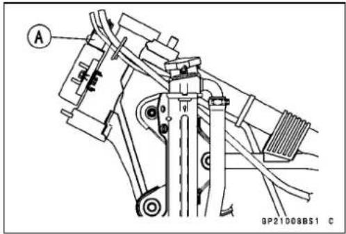
★ Ifthereismoreresistancehanshowninthe table,orno handtesterreading(infinity)thestatorhasanopenlead andmustbereplaced.Muchlessthanthisresistance meansthestatorisshorted,andmu stbereplaced.
- Using the highest resistance range of the hand tester, measure the resistance between each leads and chassis ground.
★Anyhandtesterreadinglessthaninfinity(∞)indicatesa short, necessitatingstatorreplacement.
★ Ifthestatorcoilshave normalresistance, but the voltage check showed them magnetotobedefective; then therotor magnet shave probably weakened, and therotormust be replaced.
SpecialTool-HandTester:57001-1394
IgnitionSystem
SafetyInstructions

WARNING
Theignitionsystemproducesextremelyhighvoltage.Donottouchthesparkplug,ignitioncoilorignitioncoilleadwhiletheengineisrunning,oryou couldreceiveasevereelectricalshock.
CrankshaftSensorInstallation(KX65A6F \~)
- Installthecrankshaftsensorsothattheairgap(clearance betweentheflywheelandthecrankshaftsensorcore)has correctclearance(seeFlywheelMagnetoInstallation).
CrankshaftSensorAirGapAdjustment(KX65A6F \~)
- Removethemagnetocover.
- Loosenthecrankshaft sensorscrewsA.
- Inserta0.5mmthicknessgauge[B]betweenthecrank-shaftsensorcoreandthetimingplate.
- Whilepressingthecrankshaftsensortowardthemagneto flywheel, tightenthecoilscrewsandremovethethickness gauge.
- Checktheairgap(SeeFlywheelMagnetoInstallation). Crankshaft Sensor Air Gap: 0.4 \~ 0.6 mm (0.016 \~ 0.024 in.)
★ If the air gap is not within the specified range, read just the gap.
CrankshaftSensorInspection(KX65A6F \~)
- Removethefollowing MagnetoLeadConnectorA
- Setthehandtester[B]tothe×100Ω rangeandconnect ittothemagnetoleadconnector(crankshaftsensorlead) connector.
SpecialTool-HandTester:57001-1394
★ Ifthereismoreresistancethanthespecifiedvalue,the coilhasanopenleadandmustbereplaced.Muchless thanthisresistancemeansthecoilisshorted,andmust bereplaced.
CrankshaftSensorResistance
W/G \~ W/R Leads: 396 \~ 594 Ω (× 100 Ω)
- Using the highest resistance range of the hand tester, measure the resistance between the crankshaft sensor leads and chassis ground.
★Anyhandtesterreadinglessthaninfinity(∞)indicatesa short, necessitatingreplacementofthestator.
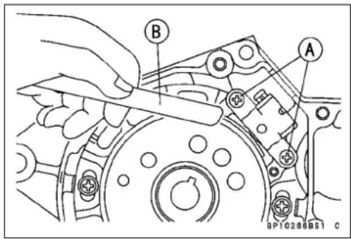
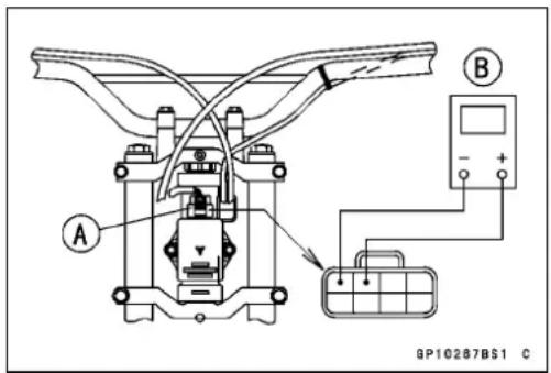
IgnitionSystem
CrankshaftSensorPeakVoltageInspection (KX65A6F \~)
- Disconnectthemagnetoleadconnector[C].
- Setthehandtester[B]tothe×25VDCrange,andconnectitacommerciallyavailablePeakvoltageadapterAasshowninthediagram.
- ConnecttheblackleadoftheadaptertoWhite/Green leadandredleadtoWhite/Redleadofthemagnetolead adapter.
- Kickingtheprimarykick,turntheengine4\~ 5seconds withthetransmissiongearinneutraltomeasurethe crankshaftsensorpeakvoltage.
- Repeatthemeasurement5ormoretimes.
CrankshaftSensorPeakVoltage
Standard:
4.0Vormore
SpecialToos-HandTester:57001-1394
PeakVoltageAdapter:57001-1415
Type:KEK-54-9-B

WARNING
Electricalequipmentcancauseseriouselectrical shock.Toavo idbeingshocked,donottouchthe metalportionoftheprobewhenmeasuringvoltage.
★ If the voltage is less than the specified, replace the pickup coil.
IgnitionCoilRemoval
- Remove:
Seat
SideCovers
Shroud
FuelTank - DisconnecttheignitioncoilprimaryleadA.
- Pulltheplugcapoffthesparkplug.
- Unscrewthemountingbolts[B], andremovetheignition coil[C].
IgnitionCoilInstallation
- Installationisthereverseofremoval.
Torque-IgnitionCoilMountingBolts:8.8N·m(0.90kgf·m, 78in·lb)
IgnitionCoilInspection
Measuring arcing distance
Thermostaccuratetestfordeterminingtheconditionof theignitioncoilismadebymeasuringarcingdistanceusing thecoiltesterforthe3-needlemethod.
- Removetheignitioncoil.
- Connecttheignitioncoil(withthesparkplugcapleftinstalledonthesparkpluglead)Atothetester[B],and measurethearcingdistance.

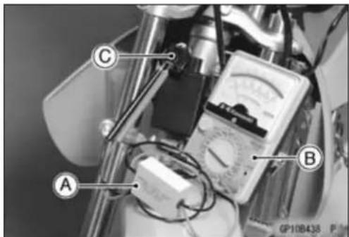
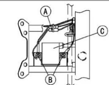
VIEWED FROM FRONT
GP100501S1 C

IgnitionSystem

WARNING
Toavoidextremelyhighvoltageshocks, donot touchthecoilorlead.
★ Ifthedistancereadingislessthanthespecifiedvalue,the ignitioncoilorsparkplugcapsdefective.
3 Needle Arcing Distance Standard: 7 mmormore
- Todeterminewhichpartisdefective,measurethearcing distanceagainwiththesparkplugcapremovedfromthe ignitioncoillead.
★ Ifthearcingdistanceissubnormalasbefore,thetrouble iswiththeignitioncoilitself. Ifthearcingdistanceisnow normal,thetroubleiswiththesparkplugcap. C:KX65A6F\~
MeasuringCoilResistance
If the arcing tester is not available, the coil can be checked for a broken or badly shorted winding with an ohmmeter. However, an ohmmeter cannot detect layer shorts and shorts resulting from insulation breakdown underhighvoltage.
- Removetheignitioncoil.
- Measure the primary winding resistance A.
○Connectanohmmeterbetweenthecoilterminals.
○Setthemetertothe×1Ω range,andreadthemeter. KX65A6F[C]
- Measurethesecondarywindingresistance[B].
○Pullthesparkplugcapoffthelead. - Connectanohmmeterbetweenthesparkplugleadand thegroundleadterminal.
- Setthemetertothe×1kΩ range,andreadthemeter.
★ Ifthemeterdoesnotreadasspecified, replacethecoil.
★ Ifthemeterreadsasspecified, the ignition coil windings are probably good. However, if the ignition system still does not perform as it should after all other components have been checked, testreplacethe coil with one known tobegood.
IgnitionCoilWindingResistance
Primary Windings: 0.26 \~ 0.36 Ω (× 1 Ω)
Secondary Windings: 2.64 \~ 3.57 Ω (× 1 kΩ)
KX65A6F\~
PrimaryWindings: 0.36 \~ 0.48 Ω (× 1 Ω)
Secondary Windings: 5.4 \~ 7.4 Ω (× 1 kΩ)
- Checkthesparkplugleadforvisibledamage.
★Ifthesparkplugleadisdamaged,replacethecoil.

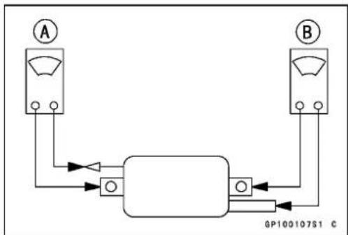

IgnitionSystem
SparkPlugCleaningandInspection
- Removethesparkplug, and visually inspectit.
- Cleanthesparkplug, preferablyinasandblastingdevice, andthencleanoffanyabrasiveparticles. Theplugmay also be cleaned using a high flash-points solvent and a wire brush or others suitable tool.
★ Ifthesparkplugelectrodesarecorrodedordamaged, oriftheinsulatoriscracked, replacetheplug. Usethe standardsparkplug.
Torque-SparkPlug:26N·m(2.6kgf·m,19ft·lb)
SparkPlugGapInspection
- MeasurethegapAwithawire-typethicknessgauge.
★ Ifthegapisincorrect, carefullybendthesideelectrode [B]withasuitabletooltoobtainthecorrectgap.
SparkPlugGap
Standard: 0.5\~0.6mm
CDIUnitRemoval
- Turnthehandlebartotheright. (KX65-A1\~A6)
- DisconnecttheharnessconnectorA.
- Unscrewthemountingbolt[B]andremovetheCDIUnit [C].
KX65A6F\~:
- DisconnecttheharnessconnectorA.
- RemovetheCDIUnitmountingbolts[B]andremovethe CDIUnit[C].
Torque-CDIUnitMountingBolts:8.8N·m(0.90kgf·m,78in·lb)
CDIUnitInspection
NOTICE
When inspecting the CDIUnit observ the following to avoid damage to the CDIUnit.
DonotdisconnecttheCDIUnitwhiletheengineis running.
ThismaydamagetheCDIUnit.

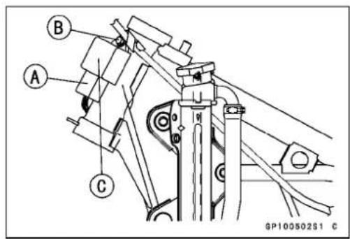
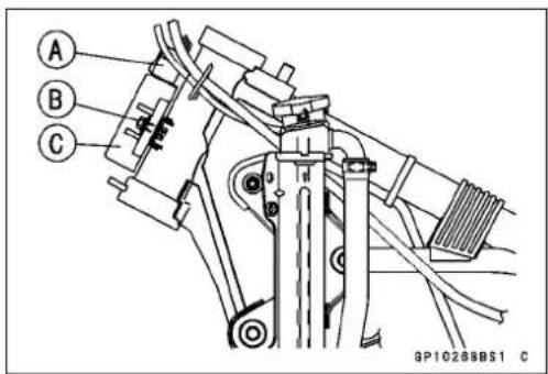
IgnitionSystem
IgnitionCoilPrimaryPeakVoltageCheck
- Remove:
Shrouds
SideCovers
Seat
FuelTank
- DisconnectthesparkplugcapfromthesparkplugA.
- Connectthenewsparkplug[B]tothesparkplugcap, thengroundittotheengine.
NOTE
○ Measure the voltage with each lead connected correctly. The correct value may not be obtained if disconnected.
○ Maintainthecorrectvalueofcompressionpressurefor thecylinder.(Besuretomeasurethevoltagewiththe sparkpluginstalledtothecylinderhead.)
- ConnectthepeakvoltageadapterAbetweenheterminalofprimarylead(orange)andgroundconnectionofthe leadoftheignitioncoil[B].
SpecialTool-PeakVoltageAdapter:57001-1415
Type: KEK-54-9-B
HandTester:57001-1394
Connection:
TesterPositive→ GroundLead[C]
TesterNegative→OrangeLead[D]
- Shiftthegeartotheneutralposition, thenpushtheengine stopbutton.
- Crank the engine by kicking the pedal several times to measure the peak voltage of the primary ignition coil.
PeakVoltage: DC115Vorabove

WARNING
Electrical equipment can cause serious electrical shock. To avoid being shocked, do not touch the metal portion of the probewhen measuring voltage.
★Ifthevoltageislessthanthespecifiedvalue,seethenext page.


Troubleshooting

flowchart
graph TD
    A["Faulty ignition (Malfunctioned engine)"] --> B["Wiring and connect portion of the ignition system inspection"]
    B -->|Good| C["Spark plug inspection"]
    B -->|No good| D["Repair"]
    C -->|Good| E["Spark plug cap inspection"]
    C -->|No good| F["Replace"]
    E -->|Good| G["Ignition coil primary peak voltage inspection"]
    E -->|No good| H["Replace"]
    G -->|Good| I["Voltage is specified but faulty ignition"]
    G -->|No good. Voltage is none or almost none.| J["Defective ignition coil"]
    I --> K["Replace"]
    J --> L["Inspect"]
    L --> M["1. Adapter connection is incorrect or adapter is directive."]
    L --> N["2. Engine stop switch (button)"]
    L --> O["3. Crankshaft sensor peak voltage (KX65A6F)"]
    L --> P["4. Exciter coil peak voltage"]
    Q["Inspect"] --> R["1. Speed of cranking engine is slow. (Increase force of kicking engine.)"]
    Q --> S["2. Lower resistance in the tester. (Use KAWASAKI Hand Tester)"]
    Q --> T["3. Lacking of sampling (Sampling few times)"]
    Q --> U["4. Crankshaft sensor peak voltage (KX65A6F)"]
    Q --> V["5. Exciter coil peak voltage"]
    R --> W["C.D.I Unit is defective"]
    S --> W
    T --> W
    U --> W
    V --> W
    W --> X["Replace the malfunctioned parts or inspect in proper way"]
    X --> Y["No good"]
    Y --> Z["Replace the malfunctioned parts or inspect in proper way"]
IgnitionSystem
Exciter(Stator)CoilPeakVoltageCheck
- DisconnecttheconnectoroftheharnessfromtheCDI Unit.
- Tocheckthepeakvoltage,dothefollowingprocedures.
NOTE
○ Measure the voltage with each lead connected correctly. The correct value may not be obtained if disconnected.
○ Maintain the correct value of compression pressure for the cylinder (Besuretomeasure the voltage with the spark plugin installed to the cylinder head).
○ConnectthepeakvoltageadapterAofthetestertothe terminalsoftheharnessconnector[B].
SpecialTool-PeakVoltageAdapter:57001-1415
Type:KEK-54-9-B
HandTester:57001-1394
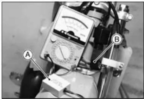
natural_image
Close-up of an analog multimeter with labeled points A and B, showing measurement scales and wiring (no readable text beyond labels)Connection:
AdapterPositive→ Black/RedLead
AdapterNegative→ Black/WhiteLead
○Cranktheenginebykick ingthepedalseveraltimesto measurethepeakvoltageoftheexciter(stator)coil.
PeakVoltageDC100Vorabove
★ If the voltage is less than the specified, check the exciter (stator) coil.
EngineStopFunctionCheck
- Disconnecttheenginestopbutton(switch)leadsA.
- Starttheengine.
- Groundthestopbutton(switch)lead[B]ofthemainharnesssidewhiletheengineisrunning.
★Iftheenginedoesnotstop,theCDIUnitisdefective.

EngineStopButtonElectricCurrentCheck(KX65A6F \~)
- Disconnecttheenginestopbutton(switch)leadconnector.
- Starttheengine.
- Groundthestopbutton(switch)black/yellowleadofthe magnetoleadwhiletheengineisrunning.
★Iftheengine does not stop, replace the CDI Unit.
Appendix
TableofContents
Troubleshooting Guide 14-2
General Lubrication 14-6
Lubrication (Periodic Maintenance) 14-6
Nut, Bolt, and Fastener Tightness 14-7
Tightness Inspection 14-7
Unit Conversion Table 14-8
TroubleshootingGuide
NOTE
○ Thisisnotanexhaustivelist, giving every possible cause foreach problem listed. It is meant simply as a rough guideto assist the troubleshooting for some of them more common difficulties.
EngineDoesn'tStart, Starting Difficulty:
Transmissiongearorbearingseizure
Kickshaftreturnspringbroken
Kickratchetgearnotengaging
Nofuelflow:
Nofuelintank
Fueltapturnedoff
Tankcapairventobstructed
Fueltapclogged
Fuellineclogged
Floatvalveclogged
Engineflooded:
Floatleveltoohigh
Floatvalvewornorstuckopen
Startingtechniquefaulty
(when flooded, kick with the throttle fully opento allow more air to reach the engine.)
Nospark;sparkweak:
Sparkplugdirty,broken,ormaladjusted
Sparkplugcaporhightensionwiringtrouble
Sparkplugcapnotingoodcontact
Sparkplugincorrect
CDIUnittrouble
Ignitioncoiltrouble
Ignitioncoilresistoropen
Flywheelmagnetodamaged
Wiringshortedoropen
Fuel/airmixtureincorrect:
Idleadjustingscrewmaladjusted
Slowjetorairpassageclogged
Aircleanerclogged,poorlysealed,ormissing
Starterjetclogged
CompressionLow:
Sparkplugloose
Cylinderheadnotsufficientlytightened down
Cylinder, pistonworn
Pistonringbad(worn,weak, broken, or sticking)
Pistonringandclearanceexcessive
Cylinderheadgasketdamaged
Cylinderheadwarped
Cylinderbasegasketdamaged
Readvalvedamaged
Cylindernutloose
PoorRunningatLowSpeed:
Sparkweak:
Sparkplugdirty,broken,ormaladjusted
Sparkplugcaporhightensionwiringtrouble
Sparkplugcapshortedornotingoodcontact
Sparkplugincorrect
CDIUnittrouble
Ignitioncoiltrouble
Flywheelmagnetodamaged
Ignition coil lead or CDI Unit lead not in good contact
Fuel/airmixtureincorrect:
Idleadjustingscrewmaladjusted
Slowjetorairpassageclogged
Aircleanerclogged,poorlysealed,ormissing
Chokeplungerstuckopen
Floatleveltoohighortoolow
Fueltankairventobstructed
Carburetorholderloose
Aircleanerductloose
CompressionLow:
Sparkplugloose
Cylinderheadnotsufficientlytightened down
Cylinder, pistonworn
Pistonringbad(worn, weak,broken,or sticking)
Pistonring/landclearanceexcessive
Cylinderheadgasketdamaged
Cylinderheadwarped
Cylinderbasegasketdamaged
Reedvalvedamaged
Cylindernutloose
Other:
CDIUnittrouble
Transmissionoilviscositytoohigh
Brakedragging
PoorRunningorNoPoweratHigh Speed:
Firingincorrect:
Sparkplugdirty,damaged,ormaladjusted
Sparkplugcaporhightensionwiringdam- aged
Sparkplugcapshortedornotingoodcontact
Sparkplugincorrect
CDIUnittrouble
Ignitioncoiltrouble
TroubleshootingGuide
Flywheelmagnetodamaged
IgnitioncoilleadorCDIUnitleadnotingood contact
Fuel/airmixtureincorrect:
Mainjetcloggedorwrongsize
Jetneedleorneedlejetworn
Jetneedleclipinwrongposition
Floatleveltoohighortoolow
Airjetorairpassageclogged
Aircleanerclogged,poorlysealed,ormissing
Chokeplungerstuckopen
Fueltocarburetorinsufficient
Waterorforeignmatterinfuel
Fueltankairventobstructed
Carburetorholderloose
Aircleanerductloose
Fueltapclogged
Fuellineclogged
Compressionlow:
Sparkplugloose
Cylinderheadnotsufficientlytightened down
Cylinder, pistonworn
Pistonringbad(worn,weak,broken,or sticking)
Pistonring/andclearanceexcessive
Cylinderheadgasketdamaged
Cylinderheadwarped
Cylinderbasegasketdamaged
Reedvalvedamaged
Cylindernutloose
Enginerpmwillnotriseproperly:
Chokeplungerstuckopen
Floatleveltoohighortoolow
Mainjetclogged
Throttlevalvedoesnotfullyopen
Aircleanerclogged
Mufflerclogged
Waterorforeignmatterinfuel
Cylinderexhaustportclogged
Brakedragging
Clutchslipping
Overheating
Transmissionoilleveltoohigh
Transmissionoilviscositytoohigh
Crankshaftbearingwornordamaged
Knocking:
Carbonbuiltupincombustionchamber
Fuelpoorqualityorincorrect
Sparkplugincorrect
CDIUnittrouble
Overheating:
Firingincorrect:
Sparkplugdirty, broken, ormaladjusted
Sparkplugincorrect
CDIUnittrouble
Fuel/airmixtureincorrect:
Mainjetcloggedorwrongsize
Fuellevelincarburetorfloatbowltoolow
Carburetorholderloose
Aircleanerpoorlysealed,ormissing
Aircleanerductpoorlysealed
Aircleanerclogged
Compressionhigh:
Carbonbuiltupincombustionchamber
Engineloadfaulty:
Brakedragging
Clutchslipping
Transmissionoilleveltoohigh
Transmissionoilviscositytoohigh
Lubricationinadequate:
Transmissionoilleveltoolow
Transmissionoilpoorqualityorincorrect
Coolantincorrect:
Coolantleveltoolow
Coolantdeteriorated
Coolingsystemcomponentincorrect:
Radiatorclogged
Radiatorcaptrouble
Waterpumpnotrotating
ClutchOperationFaulty:
Clutchslipping:
Noclutchleverplay
Clutchcablemaladjusted
Clutchinnercablecatching
Frictionplatewornorwarped
Steelplatewornorwarped
Clutchspringbrokenorweak
Clutchreleasemechanismtrouble
Clutchhuborhousingunevenlyworn
Clutchnotdisengagingproperly:
Clutchleverplayexcessive
Clutchplatewarpedortoorough
Clutchspringtensionuneven
Transmissionoildeteriorated
Transmissionviscositytoohigh
Transmissionoilleveltoohigh
Clutchhousingfrozenondriveshaft
Clutchreleasemechanismtrouble
GearShiftingFaulty:
Doesn'tintogear;shiftpedaldoesn't
return:
Clutchnotdisengaging
Shiftforkbentorseized
Gearstuckontheshaft
Gearpositioningleverbinding
Shiftreturnspringweakorbroken
Shiftreturnspringpinloose
Shiftmechanismarmspringbroken
Shiftmechanismarmbroken
Shiftdrumbroken
TroubleshootingGuide
Jumpsoutofgear:
Shiftforkworn
Geargrooveworn
Geardogsand/ordogholesworn
Shiftdrumgrooveworn
Gearpositioningleverspringweakorbroken
Shiftforkguidepinworn
Driveshaft, outputshaft, and/orgear splinesworn
Overshifts:
Gearpositioningleverspringweakorbroken
Shiftmechanismarmspringbroken
AbnormalEngineNoise:
Knocking:
CDIUnittrouble
Carbonbuiltupincombustionchamber
Fuelpoorqualityorincorrect
Sparkplugincorrect
Overheating
Pistonslap:
Cylinder/pistonclearanceexcessive
Cylinder, pistonworn
Connectingrodbent
Pistonpin, pistonpinholeworn
Othernoise:
Connectingrodsmallendclearanceexcessive
Connectingrodbigendclearanceexcessive
Pistonringworn, brokenorstuck
Pistonseizureordamaged
Cylinderheadgasketleaking
Exhaustpipeleakingatcylinderheadconnection
Crankshaftrunoutexcessive
Enginemountsloose
Crankshaftbearingworn
Primarygearwornorchipped
AbnormalDriveTrainNoise
Clutchnoise:
Clutchhousing/frictionplateclearanceexcessive
Clutchhousinggear/primarygearbacklash excessive
Metalchipjammedinclutchhousinggear teeth
Transmissionnoise:
Crankcasebearingwornordamaged
Transmissiongearwornorchipped
Metalchipjammedingearteeth
Transmissionoilinsufficientortoothin
Kickratchetgearnotproperlydisengaging fromkickgear
Outputshaftidlegearwornorchipped
Drivechainnoise:
Drivechainadjustedimproperly
Chainworn
Rearand/orenginesprocket(s)worn
Chainlubricationinsufficient
Rearwheelmisaligned
AbnormalFrameNoise:
Frontforknoise:
Oilinsufficientortoothin
Springweakorbroken
Rearshockabsorbernoise:
Shockabsorberdamaged
Discbrakenoise:
Padinstalledincorrectly
Padsurfaceglazed
Discwarped
Calipertrouble
Cylinderdamaged
Othernoise
Bracket, nut, bolt, etc. not properly mountedortightened
ExhaustSmoke:
Excessivewhitesmoke:
Throttlecablemaladjusted
Brownishsmoke:
Aircleanerclogged
Mainjettoolargeoffallenout
Chokeplungerstuckopen
Floatleveltoohigh
Handling and/or Stability
Unsatisfactory:
Handlebarhardtoturn:
ControlCableroutingincorrect
Wiringroutingincorrect
Steeringstemnuttootight
Bearingballdamaged
Bearingracedentedorworn
Steeringstembearinglubricationinadequate
Steeringstembent
Tireairpressuretoolow
Handlebarshakesorexcessivelyvibrates:
Tireworn
Swingarmsleeveorneedlebearingdam- aged
Rimwarped,ornotbalanced
Front, rearaxlerunoutexcessive
Wheelbearingworn
Handlebarclamploose
Steeringstemheadnutloose
Handlebarpullstooneside:
Framebent
TroubleshootingGuide
Wheelmisalignment
Swingarmbentortwisted
Swingarmpivotshafrunoutexcessive
Steeringmaladjusted
Steeringstembent
Frontforklegbent
Right/leftfrontforkoilleveluneven
Shockabsorptionunsatisfactory:
(Toohard)
Frontforkoilexcessive
Frontforkoilviscositytoohigh
Frontforklegbent
Tireairpressuretoohigh
Rearshockabsorbermaladjusted
(Toosoft)
Frontforkoilinsufficientand/orleaking
Frontforkoilviscositytoolow
Frontfork, rearshockabsorberspringweak
Rearshockabsorbergasleaking
Rearshockabsorbermaladjusted
BrakeDoesn'tHold:
Discbrake:
Airinthebrakeline
Padordiscworn
Brakefluidleak
Discwarped
Contaminatedpads
Brakefluiddeteriorated
Primaryorsecondarycupdamaged
Mastercylinderscratchedinside
Brakemaladjustment(leverorpedalplay excessive)
14-6APPENDIX
GeneralLubrication
Lubrication(PeriodicMaintenance)
- Beforelubricatingeachpart,cleanoffanyrustyspotswith rustremoverandwipeoffanygrease,oil,dirt,orgrime.
- Lubricatethepointslistedbelowwithindicatedlubricant.
NOTE
○ Wheneverthevehiclehasbeenoperatedunder wetorrainyconditions,orespeciallyafterusing a high-pressurewaterspray,performthegenerallubrication.
Pivots:LubricatewithMotorOil
ClutchLever
BrakeLever
KickPedal
ShiftPedal
DriveChain
Points:LubricatewithGrease[A].
ClutchInnerCableUpperandLowerEnds
ThrottleInnerCableUpperEnds
SwingarmPivot
Tie-RodPivot
RockerarmPivot
SteeringStemBearing
Cables: Lubricate with Rust Inhibitor.
ThrottleCables
ClutchCableA
- With the cabled disconnected at the both ends, the cable A should move freely within the cable housing.
★ Ifcablemovementisnotfreeafterlubricating,ifthecable isfrayed,orifthecablehousingiskinked,replacethe cable.


natural_image
Line drawing of hands holding a syringe with a pointer and labeled point A (no text or symbols beyond label)
Nut, Bolt, and Fastener Tightness
TightnessInspection
- Checkthetightnessofboltsandnutslistedhere. Also, checktoseethateachcotterpinisinplaceandingood condition.
NOTE
○ Fortheenginefasteners, check the tightness of them when the engine is cold (at room temperature).
★ Ifthereareloosefasteners,retorquethemtothespecifiedtorquefollowingthespecifiedtighteningsequence. Refertotheappropriatechapterfortorquespecifications. Iftorquespecificationsarenotintheappropriatechapter, seetheStandardTorqueTable.Foreachfastener,first loosenitby1/2turn,thentightenit.
★Ifcotterpinsaredamaged, replacethemwithnewones.
Nut,BoltandFastenertobechecked
Wheels:
SpokeNipples
FrontAxleNut
RearAxleNut
FinalDrive:
ChainAdjusterLocknuts
Brakes:
MasterCylinderClampBolts
CaliperMountingBolts
BrakePedalMountingBolt
Suspension:
FrontForkClampBolts
RearShockAbsorberMountingBoltandNut
SwingarmPivotShaftNut
Tie-rodMountingNut
Steering:
SteeringStemHeadNut
HandlebarClampBolts
SteeringStemNut
Engine:
EngineMountingNuts
EngineBracketNuts
CylinderHeadNuts
ShiftPedalBolt
MufflerMountingBoltandNut
KickPedalBolt
Others:
RearFrameMountingBolts
FrontFenderMountingBolt
PrefixesforUnits:
| PrefixSymbol | Power | |
| megaM×1000000 | ||
| kilok×1000 | ||
| centic× 0 . 0 1 | ||
| millim×0.001 | ||
| microμ | ×0.000001 | |
UnitsofMass:
| kg | × | 2.205 | = | lb |
| g | × | 0.03527 | = | oz |
UnitsofVolume:
| L | × | 0.2642 | = | gal (US) |
| L | × | 0.2200 | = | gal (imp) |
| L | × | 1.057 | = | qt (US) |
| L | × | 0.8799 | = | qt (imp) |
| L | × | 2.113 | = | pint(US) |
| L | × | 1.816 | = | pint (imp) |
| mL | × | 0.03381 | = | oz (US) |
| mL | × | 0.02816 | = | oz (imp) |
| mL | × | 0.06102 | = | cu in |
UnitsofForce:
| N | × | 0.1020 | = | kg |
| N | × | 0.2248 | = | lb |
| kg | × | 9.807 | = | N |
| kg | × | 2.205 | = | lb |
UnitsofLength:
| km | × | 0.6214 | = | mile |
| m | × | 3.281 | = | ft |
| mm | × | 0.03937 | = | in |
UnitsofTorque:
| N·m | × | 0.1020 | = | kgf·m |
| N·m | × | 0.7376 | = | ft·lb |
| N·m | × | 8.851 | = | in·lb |
| kgf·m | × | 9.807 | = | N·m |
| kgf·m | × | 7.233 | = | ft·lb |
| kgf·m | × | 86.80 | = | in·lb |
UnitsofPressure:
| kPa | × | 0.01020 | = | kgf/cm ^2 |
| kPa | × | 0.1450 | = | psi |
| kPa | × | 0.7501 | = | cmHg |
| kgf/cm ^2 | × | 98.07 | = | kPa |
| kgf/cm ^2 | × | 14.22 | = | psi |
| cmHg | × | 1.333 | = | kPa |
UnitsofSpeed:
| km/h | × | 0.6214 | = | mph |
UnitsofPower:
| kW | × | 1.360 | = | PS |
| kW | × | 1.341 | = | HP |
| PS | × | 0.7355 | = | kW |
| PS | × | 0.9863 | = | HP |
UnitsofTemperature:

line
| Position | Value (°C) | |---|---| | 1 | -40 | | 2 | -20 | | 3 | -4 | | 4 | -20 | | 5 | 0 | | 6 | 20 | | 7 | 32 | | 8 | 40 | | 9 | 60 | | 10 | 68 | | 11 | 80 | | 12 | 100 | | 13 | 104 | | 14 | 120 | | 15 | 140 | | 16 | 160 | | 17 | 176 | | 18 | 180 | | 19 | 200 | | 20 | 212 | | 21 | 220 | | 22 | 248 | | 23 | 240 | | 24 | 260 | | 25 | 280 | | 26 | 284 | | 27 | 300 | | 28 | 320 | | 29 | -40 | | 30 | -20 | | 31 | -17.8 | | 32 | -4.4 | | 33 | 0 | | 34 | 4.4 | | 35 | 26.7 | | 36 | 20 | | 37 | 48.9 | | 38 | 60 | | 39 | 71.1 | | 40 | 80 | | 41 | 93.3 | | 42 | 100 | | 43 | 116 | | 44 | 120 | | 45 | 138 | | 46 | 140 | | 47 | 160 | | 48 | -40 | The chart displays the deviation of temperature from the center of the axis (labeled as 'F' and 'C') for two different temperature conditions (labeled as 'F' and 'C'). The values are expressed as fractions of a constant (e.g., (9(°C+40)/5) -4 = °F). The chart is divided into two sections: 'Temperature Difference' (lower section) and 'Temperature Difference' (upper section). The values above the lines represent the absolute difference between the two temperature conditions, while the lower section shows the corresponding temperature deviation. The chart is annotated with a mathematical expression on the left side.MODELAPPLICATION
| YearModel | BeginningFrameNo | |
| 2000KX65-A1 | JKBKEAC□YA000001orJKAKX065AAA000001 | |
| 2001KX65-A2 | JKBKXEAC□1A009001orJKBKX065AAA009001 | |
| 2002KX65-A3 | JKBKXEAC□2A016001orJKBKX065AAA016001 | |
| 2003KX65-A4 | JKBKXEAC□3A027001orJKBKX065AAA027001 | |
| 2004KX65-A5 | JKBKXEAC□4A036001orJKBKX065AAA036001 | |
| 2005KX65-A6 | JKBKXEAC□5A042001orJKBKX065AAA042001 | |
| 2006KX65A6F | JKBKXEAC□6A048001orJKBKX065AAA048001 | |
| 2007KX65A7F | JKBKXEAC□7A054001JKBKX065AAA054001 | |
| 2008KX65A8F | JKBKXEAC□8A059001orJKBKX065AAA059001 | |
| 2009KX65A9F | JKBKXEAC□9A065001orJKBKX065AAA065001 | |
| 2010KX65AAF | JKBKXEAC□AA070001orJKBKX065AAA070001 | |
| 2011KX65ABF | JKBKXEAC□BA072001orJKBKX065AAA072001 | |
□: Thisdigitintheframenumberchangesfromonemachinetoanother.


- Motorcycle ServiceManual
- QuickReferenceGuide
- Foreword
- HowtoUsethisM anual
- DANGER
- WARNING
- CAUTION
- NOTICE
- NOTE
- GeneralInformation
- TableofContents
- BeforeServicing
- Especiallynotethefollowing:
- (1)Dirt
- (2)BatteryGround
- Installation, Assembly
- TighteningSequence
- (5)Torque
- (6)Force
- (7)Edges
- (8)High-FlashPointSolvent
- (9)Gasket,O-ring
- (10)LiquidGasket,LockingAgent
- (11)Press
- (12)BallBearingandNeedleBearing
- (13)OilSealandGreaseSeal
- Circlip, Retaining Ring, and Cotter Pin
- (15)Lubrication
- (16)DirectionofEngineRotation
- (17)ReplacementParts
- (18)ElectricalLeads
- Two-ColorElectrical
- (19)Inspection
- (20)Specifications
- ModelIdentification
- 1-8GENERALINFORMATION
- PeriodicMaintenanceChart
- 1-10GENERALINFORMATION
- TorqueandLockingAgent
- 1-14GENERALINFORMATION
- SpecialToolsandSealants
- 1-16GENERALINFORMATION
- Cable, Wire and Hose Routing
- KX65A6F\~
- FuelSystem
- ExplodedView
- ThrottleGripandCable
- FreePlayInspection
- FreePlayAdjustment
- Throttle Cable Installation
- CableLubrication
- CableInspection
- Carburetor
- IdleSpeedInspection
- IdleSpeedAdjustment
- ServiceFuelLevelInspection
- ServiceFuelLevelAdjustment
- CarburetorRemoval
- Carburetor Installation
- Fuelspilledfromthecarburetorishazardous.
- FuelInspection
- CarburetorDisassembly
- CarburetorAssembly
- CarburetorCleaning
- CarburetorInspection
- AirCleaner
- AirCleanerHousingRemoval
- AirCleanerHousingInstallation
- ElementRemoval
- ElementInstallation
- ElementCleaningandInspection
- FuelTank
- FuelTankRemoval
- FuelTankInstallation
- FuelTapRemoval
- FuelTapInstallation
- FuelTapInspection
- FuelTankandTapCleaning
- ReedValve
- ReedValveRemoval
- ReedValveInstallation
- ReedValveInspection
- FuelHose
- FuelHosesandConnectionsCheck
- CoolingSystem
- 3-4COOLINGSYSTEM
- Coolant
- CoolantLevelInspection
- CoolantDeteriorationInspection
- CoolantDraining
- CoolantFilling
- AirBleeding
- CoolingSystemPressureTesting
- CoolingSystemFlushing
- 3-8COOLINGSYSTEM
- Disassembly and Assembly Precautions
- WaterPump
- WaterPumpShaftRemoval
- KX65A6F\~:
- WaterPumpShaftInstallation
- OilSealRemoval
- OilSealInstallation
- Radiator
- RadiatorRemoval
- RadiatorInstallation
- RadiatorInspection
- Donotteartheradiatortubeswhilestraightening thefins.
- CapInspection
- RadiatorCapReliefPressure:
- FillerNeckInspection
- WaterHoses, BreatherHoseInspection
- WaterHoses, Breather Hose Installation
- EngineTopEnd
- CylinderHead
- CylinderCompressionMeasurement
- CylinderCompression
- Cylinder
- CylinderRemoval
- CylinderInstallation
- PistonRemoval
- PistonInstallation
- CylinderWearInspection
- CylinderInsideDiameter
- PistonDiameterMeasurement
- PistonDiameter
- Piston/CylinderClearancelnspection
- Piston/CylinderClearance
- PistonRing, PistonRing Groove Inspection
- PistonRingEndGapInspection
- Piston, PistonPin, ConnectingRodWear Inspection
- Muffler(ExpansionChamber)
- MufflerRemoval
- MufflerInstallation
- MufflerBaffleReplacement
- 4-12ENGINETOPEND
- EngineRightSide
- ClutchCable
- ClutchLeverFreePlayInspection
- ClutchCableRemoval
- ClutchCableInstallation
- ClutchCableLubricationandInspection
- RightEngineCover
- RightEngineCoverRemoval
- EngineRightCoverInstallation
- RightEngineCoverDisassembly
- RightEngineCoverAssembly
- 5-10ENGINERIGHTSIDE
- Clutch
- ClutchRemoval
- ClutchInstallation
- FrictionandSteelPlatesWear, DamageInspection
- FrictionPlateThickness
- SteelPlateThickness
- FrictionandSteelPlateWarpInspection
- FrictionandSteelPlatesWarp
- SpringFreeLengthMeasurement
- FrictionPlate/ClutchHousingClearance Inspection
- ClutchHubSplineInspection
- ExternalShiftMechanism
- ExternalShiftMechanismRemoval
- ExternalShiftMechanismInstallation
- ExternalShiftMechanismInspection
- 5-14ENGINERIGHTSIDE
- PrimaryGear
- PrimaryGearRemoval
- PrimaryGearInstallation
- PrimaryGearRemoval(KX65A6F \~)
- PrimaryGearInstallation(KX65A6F \~)
- 5-16ENGINERIGHTSIDE
- Kickstarter
- KickshaftRemoval
- KickshaftInstallation
- KickstarterAssemblyDisassembly/Assembly
- IdleGearRemoval
- IdleGearInstallation
- EngineRemoval/Installation
- EngineRemoval
- EngineInstallation
- EngineBottomEnd/Transmission
- 7-2 ENGINEBOTTOMEND/TRANSMISSION
- TransmissionOil
- OilLevelInspection
- OilChange
- Crankcase
- CrankcaseSplitting
- CrankcaseDisassembly
- CrankcaseAssembly
- 7-10 ENGINEBOTTOMEND/TRANSMISSION
- Crankshaft, ConnectingRod
- CrankshaftRemoval
- CrankshaftInstallation
- CrankshaftDisassembly
- CrankshaftAssembly
- ConnectingRodBigEndRadialClearance Inspection
- ConnectingRodBigEndSeizureInspection
- ConnectingRodBigEndSideClearance Inspection
- CrankshaftRunoutInspection
- 7-12 ENGINEBOTTOMEND/TRANSMISSION
- CrankshaftAlignmentInspection
- Don'thammertheflywheelatpoint"A".
- Transmission
- ShaftRemoval
- ShaftInstallation
- ShaftDisassembly
- ShaftAssembly
- ShiftDrumandForkInstallation
- ShiftForkBendingInspection
- ShiftFork/GearGrooveWearInspection
- ShiftForkGuidePin/ShiftDrumGrooveWear Inspection
- GearDamageInspection
- GearDog/GearDogHoleDamageInspection
- BallBearingWearInspection
- Wheels/Tires
- FrontWheelInstallation
- Wheels(Rims)
- RearWheelRemoval
- RearWheelInstallation
- WheelsInspection
- Spokelnspection
- RimInspection
- AxleInspection
- Tires
- AirPressureInspection/Adjustment
- TiresInspection
- StandardTire
- TireRemoval
- TireInstallation
- HubBearings
- HubBearingRemoval
- HubBearingInstallation
- BearingInspection
- FinalDrive
- DriveChainSlackInspection
- ChainSlack
- DriveChainSlackAdjustment
- DriveChain
- WheelAlignmentInspection
- WheelAlignmentAdjustment
- DriveChainWearInspection
- DriveChainLubrication
- DriveChainRemoval
- DriveChainInstallation
- Sprockets
- EngineSprocketRemoval
- EngineSprocketInstallation
- RearSprocketRemoval
- RearSprocketInstallation
- SprocketWearInspection
- RearSprocketWarpInspection
- Brakes
- BrakeLever, BrakePedal
- BrakeLeverPlayAdjustment
- BrakePedalPosition/PedalPlayAdjustment
- BrakePedalRemoval
- 10-6BRAKES
- BrakePedallInstallation
- When working with the disc brake, observ the precautions listed below.
- BrakeFluid
- FluidLevelInspection
- FluidChange
- BleedingtheBrakeLine
- Caliper
- CaliperRemoval
- FrontBrake
- RearBrake
- CaliperInstallation
- CaliperDisassembly
- CaliperAssembly
- FluidSealDamageInspection
- DustSealandCoverDamageInspection
- PistonCylinderDamageInspection
- CaliperHolderShaftWearInspection
- BrakePadRemoval
- BrakePadInstallation
- BrakePadInspection
- FrontMasterCylinderRemoval
- FrontMasterCylinderInstallation
- MasterCylinder
- RearMasterCylinderRemoval
- RearMasterCylinderInstallation
- FrontMasterCylinderDisassembly
- RearMasterCylinderDisassembly
- Donotremovethesecondarycup[F]fromthepistonsinceremovalwilldamageit.
- MasterCylinderAssembly
- MasterCylinderInspection(VisualInspection)
- BrakeDisk
- BrakeDisclInspection
- BrakeHose
- BrakeHoseRemoval/Installation
- Brakefluidquicklyruinspaintedorplasticsurfaces;anyspilledfluidshouldbecompletelywiped upimmediatelywithwateredcloth.
- BrakeHoselnspection
- Suspension
- FrontFork
- ReboundDampingAdjustment(KX65-A3 \~)
- Theleftandrightforklegsmusthavethesame shockdamping.
- ReboundDampingAdjusterSetting
- ForkOilLevelAdjustment(Simplify)
- KX65-A3\~
- OilChange/OilLevelAdjustment(eachforkleg)
- FrontForkRemoval
- FrontForkInstallation
- FrontForkDisassembly(eachfork)
- 11-12 SUSPENSION
- FrontForkAssembly(eachfork)
- InnerTubeInspection
- GuideBushInspection
- DustSeal/OilSealInspection
- SpringTensionInspection
- ForkSpringFreeLength
- RearSuspension(Uni-Trak)
- RearShockAbsorber
- ReboundDampingForceAdjustment
- ReboundDampingAdjusterSetting Standard:11/2turnsout
- SpringPreloadAdjustment
- 11-16 SUSPENSION
- RearShockAbsorberRemoval
- RearShockAbsorberInstallation
- SpringReplacement
- 11-18 SUSPENSION
- SpringTension
- RearShockAbsorbe rScrapping
- Swingarm
- SwingarmRemoval
- SwingarmInstallation
- SwingarmBearingRemoval
- SwingarmBearingInstallation
- SpecialTool-BearingDriverSet:57001-1129
- Tie-rod,RockerArm
- Tie-rodRemoval
- Tie-rodInstallation
- RockerArmRemoval
- 11-22 SUSPENSION
- RockerArmInstallation
- NeedleBearingInspection
- Uni-TrakMaintenance
- RockerArmSleeveWearInspection
- RockerArmMountingBoltBendInspection
- Steering
- Specifications
- SteeringInspection
- SteeringAdjustment
- SteeringStem, StemBearingRemoval
- SteeringStem, StemBearingInstallation
- 12-8STEERING
- SteeringMaintenance
- StemBearingLubrication
- StemBearingWear, DamageInspection
- StemWarpInspection
- Handlebar
- HandlebarRemoval
- HandlebarInstallation
- ClutchLeverInstallation
- ElectricalSystem
- 13-2 ELECTRICAL SYSTEM
- WiringDiagram
- Precautions
- SafetyInstructions
- 13-6 ELECTRICAL SYSTEM
- Electrical Wiring
- WiringInspection
- IgnitionTiming
- IgnitionTimingAdjustment
- FlywheelMagneto
- FlywheelMagnetoRemoval
- FlywheelMagnetolnstallation
- CrankshaftSensorAirGapInspection(KX65A6F \~)
- FlywheelMagnetoInspection
- 13-10 ELECTRICAL SYSTEM
- IgnitionSystem
- CrankshaftSensorInstallation(KX65A6F \~)
- CrankshaftSensorAirGapAdjustment(KX65A6F \~)
- CrankshaftSensorInspection(KX65A6F \~)
- CrankshaftSensorPeakVoltageInspection (KX65A6F \~)
- IgnitionCoilRemoval
- IgnitionCoilInstallation
- IgnitionCoilInspection
- Measuring arcing distance
- Toavoidextremelyhighvoltageshocks, donot touchthecoilorlead.
- Needle Arcing Distance Standard: 7 mmormore
- MeasuringCoilResistance
- IgnitionCoilWindingResistance
- SparkPlugCleaningandInspection
- SparkPlugGapInspection
- CDIUnitRemoval
- CDIUnitInspection
- IgnitionCoilPrimaryPeakVoltageCheck
- Exciter(Stator)CoilPeakVoltageCheck
- Connection:
- EngineStopFunctionCheck
- EngineStopButtonElectricCurrentCheck(KX65A6F \~)
- Appendix
- TroubleshootingGuide
- EngineDoesn'tStart, Starting Difficulty:
- Nofuelflow:
- Engineflooded:
- Nospark;sparkweak:
- Fuel/airmixtureincorrect:
- CompressionLow:
- PoorRunningatLowSpeed:
- Sparkweak:
- Other:
- PoorRunningorNoPoweratHigh Speed:
- Firingincorrect:
- Enginerpmwillnotriseproperly:
- Knocking:
- Overheating:
- Compressionhigh:
- Engineloadfaulty:
- Lubricationinadequate:
- Coolantincorrect:
- Coolingsystemcomponentincorrect:
- ClutchOperationFaulty:
- Clutchslipping:
- Clutchnotdisengagingproperly:
- GearShiftingFaulty:
- Doesn'tintogear;shiftpedaldoesn't
- return:
- Jumpsoutofgear:
- Overshifts:
- AbnormalEngineNoise:
- Pistonslap:
- Othernoise:
- AbnormalDriveTrainNoise
- Clutchnoise:
- Transmissionnoise:
- Drivechainnoise:
- AbnormalFrameNoise:
- Frontforknoise:
- Rearshockabsorbernoise:
- Discbrakenoise:
- Othernoise
- ExhaustSmoke:
- Excessivewhitesmoke:
- Brownishsmoke:
- Handling and/or Stability
- Unsatisfactory:
- Handlebarhardtoturn:
- Handlebarshakesorexcessivelyvibrates:
- Handlebarpullstooneside:
- Shockabsorptionunsatisfactory:
- BrakeDoesn'tHold:
- Discbrake:
- 14-6APPENDIX
- GeneralLubrication
- Lubrication(PeriodicMaintenance)
- Pivots:LubricatewithMotorOil
- Points:LubricatewithGrease[A].
- Cables: Lubricate with Rust Inhibitor.
- Nut, Bolt, and Fastener Tightness
- TightnessInspection
- Nut,BoltandFastenertobechecked
Brand : KAWASAKI
Model : KX65 (2010)
Category : Motorcycle