
ER-6n (2006) - Motorcycle KAWASAKI - Free user manual and instructions
Find the device manual for free ER-6n (2006) KAWASAKI in PDF.


| Brand | Kawasaki |
| Model | ER-6n |
| Year | 2006 |
| Category | Naked motorcycle |
| Engine type | Liquid-cooled, 4-stroke, parallel twin |
| Displacement | 649 cc |
| Bore x stroke | 83.0 x 60.0 mm |
| Compression ratio | 11.3:1 |
| Fuel system | Fuel injection (DFI) |
| Transmission | 6-speed, chain drive |
| Front suspension | 41 mm telescopic fork, 125 mm travel |
| Rear suspension | Bottom-link Uni-Trak with adjustable preload, 130 mm travel |
| Front brakes | Dual 300 mm petal discs, 2-piston calipers |
| Rear brakes | Single 220 mm petal disc, 1-piston caliper |
| Overall length | 2,105 mm (82.9 in) |
| Overall width | 770 mm (30.3 in) |
| Overall height | 1,315 mm (51.8 in) |
| Seat height | 785 mm (30.9 in) |
| Wheelbase | 1,415 mm (55.7 in) |
| Curb weight | 206 kg (454 lb) |
| Fuel capacity | 16 L (4.2 US gal) |
| Maintenance interval | Every 6,000 km (3,700 mi) |
| Repair manual | Available from Kawasaki or online |
Frequently Asked Questions - ER-6n (2006) KAWASAKI
User questions about ER-6n (2006) KAWASAKI
0 question about this device. Answer the ones you know or ask your own.
Ask a new question about this device
Download the instructions for your Motorcycle in PDF format for free! Find your manual ER-6n (2006) - KAWASAKI and take your electronic device back in hand. On this page are published all the documents necessary for the use of your device. ER-6n (2006) by KAWASAKI.
USER MANUAL ER-6n (2006) KAWASAKI
natural_image
Black and white exterior view of a Kawasaki motorcycle with visible engine, wheels, and front wheel (no text or symbols)Motorcycle ServiceManual
QuickReferenceGuide
| GeneralInformation1 | |
| PeriodicMaintenance2 | |
| FuelSystem(DFI)3 | |
| CoolingSystem4 | |
| EngineTopEnd5 | |
| Clutch | 6 |
| EngineLubricationSystem | 7 |
| EngineRemoval/Installation | 8 |
| Crankshaft/Transmission | 9 |
| Wheels/Tires | 10 |
| FinalDrive | 11 |
| Brakes | 12 |
| Suspension | 13 |
| Steering | 14 |
| Frame | 15 |
| ElectricalSystem | 16 |
| Appendix | 17 |
This quick reference guidewill assist you in locating adesired topic or procedure.
- Bendthepagesbacktomatchthe blacktabofthedesiredchapternumberwiththeblacktabontheedgeateachtableofcontentspage.
- Refertothesectionaltableofcontents fortheexactpagestolocatethespecifictopicrequired.
Motorcycle ServiceManual
Allrightsreserved.Nopartsofthispublicationmaybereproduced,storedinaretrievalsystem,or transmittedinanyformorbyanymeans,electronicmechanicalphotocopying,recordingorotherwise, withoutthepriorwrittenpermissionofQualityDivision/ConsumerProducts&MachineryCompany/Kawasaki HeavyIndustries,Ltd.,Japan.
Noliability can be accepted for any inaccuracies or missions in this publication, although he very possible care has been taken to make it as complete and accurate as possible.
The right is reserved to make changes at any time without prior notice and without incurring an obligation to make such changestoproducts manufactured previously. See your Motorcycle dealer forthelatest information on product improvements incorporated after this publication.
All information contained in this publication is based on the latest product information available at the time of publication. Illustrationsandphotographsinthispublicationareintendedforreferenceuseonlyandmay notdepictactualmodelcomponentparts.
LISTOFABBREVIATIONS
| Aampere($) | lbpound(s) | ||
| ABDCafter | bottomdeadcenter | m | meter(s) |
| AC | alternatingcurrentmin | minute(s) | |
| ATDCafter | topdeadcenter | N | newton(s) |
| BBDCbefore | bottomdeadcenterPapascal(s) | ||
| BDCbottom | deadcenterPShorsepower | ||
| BTDC | before top dead center | psi | pound(s) per square inch |
| °C | degree(s) Celsius | r | revolution |
| DC | direct current | rpm | revolution(s) per minute |
| F | farad(s) | TDC | top dead center |
| °F | degree(s) Fahrenheit | TIR | total indicator reading |
| ft | foot, feet | V | volt(s) |
| g | gram(s) | W | watt(s) |
| h | hour(s) | Ω | ohm(s) |
| L | liter(s) |
Read OWNER'S MANUAL before operating.
Foreword
Thismanualisdesignedprimarilyforuseby trainedmechanicsinaproperlyequippedshop. However, it contains enough detail and basic information to make useful to the owner who desire to perform his own basic maintenance and repair work. Abasicknowledge of mechanics, the proper use of tools, and workshop procedures must be understood in order to carry out maintenance and repairs satisfactorily. Whenever the owner has insufficient experience or doubt this ability to do the work, all adjustments, maintenance, and repair should be carried out only by qualified mechanics.
Inordertoperformtheworkefficiently and toavoidcostlymistakes,readthetext,thoroughlyfamiliarizeyourselfwiththeprocedures beforestartingwork,andthendotheworkcarefullyinacleanarea.Wheneverspecialtoolsorequipmentarespecified,donotuse makeshift toolsorequipment.Precisionmeasurements canonlybemadeiftheproperinstrumentsare used,and the use of substitute tools may adverselyaffectsafeoperation.
Forthedurationofthewarrantyperiod, we recommend that all repairs and scheduled maintenancebeperformedinaccordancewith thisservicemanual. Anyownermaintenanceor repair procedure not performed in accordance withthismanualmayvoidthewarranty. Togetthelongestlifeoutofyourvehicle:
- FollowthePeriodicMaintenanceChartintheServiceManual.
- Be alert for problems and non-scheduled maintenance.
- UsepropertoolsandgenuineKawasakiMotorcycleparts. Specialtools, gauges, and testersthatarenecessary whenservicing Kawasakimotorcyclesareintroduced by the Service Manual. Genuine parts provided as sparepartsarelistedinthePartsCatalog.
- Follow the procedures in this manual carefully. Don't take shortcuts.
- Remembertokeepcompleterecordsofmaintenanceand repairwithdatesand anynew partsinstalled.
HowtoUseThisManual
Inpreparing this manual, wedivided the product into its major systems. Thesesystems became the manual's chapters. All information for particular system from adjustment through disassembly and inspection is located in single chapter.
TheQuickReferenceGuideshowsyouall oftheproduct'ssystem andassistsinlocating theirchapters.Eachchapterinturnhasitsown comprehensiveTableofContents.
The Periodic Maintenance Chartis located in the Periodic Maintenance chapter. The chart gives atimescheduleforrequiredmaintenance operations.
If you want spark plugin information, fore example, goto the Periodic Maintenance Chart first. The chart tells you how frequently to clean and gap the plug. Next, use the Quick Reference Guidetolocate the Periodic Maintenance chapter. Then, use the Table of Contents on the first page of the chapter to find the Spark Plug section.
Whenever you see these WARNING and CAUTION symbols, heed their instructions! Always follows safe operating and maintenance practices.
WARNING
This warningsymbolidentifiesspecial instructionsorprocedureswhich,ifnot correctlyfollowed,couldresultinpersonalinjury,orlossoflife.
CAUTION
Thiscautionsymbolidentifiesspecial instructionsorprocedureswhich,ifnot strictlyobserved,couldresultindam- agetoordestructionofequipment.
This manual contains four more symbols (in addition to WARNING and CAUTION) which will help you distinguish different types of information.
NOTE
○ Thisnotesymbolindicatespointsofparticularinterestformoreefficientandconvenientoperation.
- Indicatesaproceduralsteporworktobe done.
○Indicatesaproceduralsub-steporhowtodo theworkoftheproceduralstepitfollows.It alsoprecedesthetextofaNOTE.
★Indicates a conditional stepor what action to take based on the result of the test or inspection in the procedural steporsub-stepit follows.
Inmostchaptersanexplodedviewillustration of the system components follow the Table of Contents. In these illustrations you will find the instructions indicating which parts require specified tightening torque, oil, grease oralocking agent during assembly.
GeneralInformation
TableofContents
Before Servicing 1-2
Model Identification.... 1-7
General Specifications.... 1-8
TechnicalInformation-CassetteTypeTransmission....1-11
TechnicalInformation-InletAirPressureSensor....1-12
Unit Conversion Table 1-13
1-2GENERALINFORMATION
BeforeServicing
Beforestartingtopermaninspectionserviceorcarryoutadisassemblyandreassemblyoperation on a motorcycle, read the precautions given below. To facilitate actual operations, notes, illustrations, photographs, cautions, and detailed descriptions have been included in each chapter wherever necessary. This section explains the item that require particular attention during the removal and reinstallationordisassemblyandreassembly of general parts.
Especiallynotethefollowing:
BatteryGround
Beforecompletinganyserviceonthemotorcycle, disconnectthebatterywiresfromthebatterytopreventtheengine fromaccidentallyturningover.Disconnectthegroundwire (-) firstandthenthepositive (+) .Whencompletedwith the service,firstconnectthepositive (+) wiretothepositive (+) terminalofthebatterythenthenegative (-) wiretothenegativeterminal.
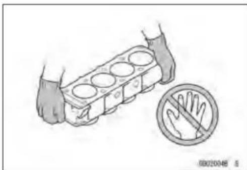
EdgesofParts
Liftlargeorheavypartswearingglovestopreventinjury frompossiblesharpedgesontheparts.
Solvent
Useahigh-flushpointsolventwhencleaningparts.High -flushpointsolventshouldbeusedaccordingtodirections ofthesolventmanufacturer.
Cleaning Vehicle before Disassembly
Cleanthevehiclethoroughlybeforedisassembly.Dirtor otherforeignmaterialsenteringintosealedareasduringveh-cledisassemblycancauseexcessivewearanddecrease performanceofthevehicle.

natural_image
Illustration of hands holding a cylindrical engine block with a no-handled hand symbol nearby (no text or labels)

natural_image
Line drawing of a motorcyclist with hands adjusting the wheel (no text or symbols)BeforeServicing
ArrangementandCleaningofRemovedParts
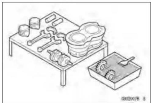
Disassembledpartsareeasytoconfuse.Arrangethe partsaccordingtotheorderthepartsweredisassembled andcleanthepartsinorderpriortoassembly.
StorageofRemovedParts
After all the parts including subassembly part have been cleaned, store the parts in a clean area. Put a clean cloth or plastics sheet over the part stop protect from any foreign material that may collect before assembly.
Inspection
Reuseofwornordamagedpartsmayleadtoseriousaccident. Visuallyinspectremovedpartsforcorrosion, discoloration, orotherdamage. Refertotheappropriatesections of this manualforservicelimitsonindividualparts. Replace thepartsifanydamagehasbeenfoundorifthepartisbeyonditsservicelimit.
ReplacementParts
ReplacementpartsmustbeKAWASAKIgenuineor recommendedbyKAWASAKI.Gaskets,O-rings,oilseals, greaseseals,circlipsorcotterpinsmustbereplacedwith newoneswheneverdisassembled.
AssemblyOrder
Inmostcasesassemblyorderisthereverseofdisassembly,however,ifassemblyorderisprovidedinthisService Manual,followtheproceduresgiven.
natural_image
Technical line drawing of a mechanical assembly with gears, gears, and components (no text or symbols)
natural_image
Isometric line drawing of a tray with various mechanical components and fixtures (no text or symbols)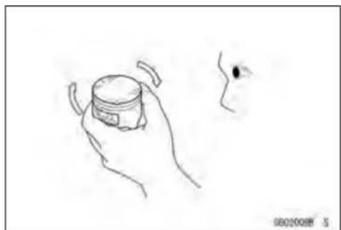
natural_image
Hand holding a small cylindrical object with a small dark mark, next to a small abstract shape (no text or symbols)

natural_image
Line drawing of hands using a tool to adjust mechanical parts on a workbench (no text or symbols)BeforeServicing
TighteningSequence
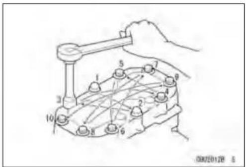
Generally, when installing apart with several bolts, nuts, or screws, start them all in their holes and tight them to as nugfit. Thentightenthem according to the specified sequence to prevent casewar page or deformation which can lead to malfunction. Conversely when loosening the bolts, nuts, or screws, first loosen allof them by about a quarter turn and then removethem. If these specified tightening sequence is not indicated, tight the fasteners alternating diagonally.
Tightening Torque
Incorrect torque applied to a bolt, nut, or screw may lead to serious damage. Tighten fastener stothespecified torque using a good quality torque wrench. Often, the tightening sequence is followed twice - initial tightening and final tightening with torque wrench.
Force
Usecommonsenseduringdisassemblyandassembly, excessiveforcecancauseexpensiveorhardtorepairdamage. Whennecessary, removescrewsthathaveanon-permanentlockingagentappliedusinganimpactdriver. Useaplastic-facedmalletwhenevertappingisnecessary.
Gasket, O-ring
Hardening, shrinkage, or damage of both gaskets and O-ringsafterdisassembly can reduce sealing performance. Remove old gaskets and clean these sealing surfaces thoroughly so that no gasket material or other material remains. Install new gaskets and replace used O-rings when re-assembling
LiquidGasket, Non-permanentLockingAgent
For application that require Liquid Gasket or a Non-permanent Locking Agent, clean the surfaces so that no oil residue remains before applying liquid gasket or non-permanent locking agent. Donot apply them excessively. Excessive application can log oil passages and causes serious damage.

natural_image
Line drawing of hands using a tool to lift a mechanical component (no text or symbols)
natural_image
Line drawing of a hand using a tool to cut or adjust a mechanical component (no text or symbols)
natural_image
Line drawing of two hands adjusting a flange with a magnified inset showing the circular opening (no text or symbols)
natural_image
Hand holding a tool applying material to a mechanical component, with a circular symbol indicating no chemical symbols (no text or labels present)BeforeServicing
Press
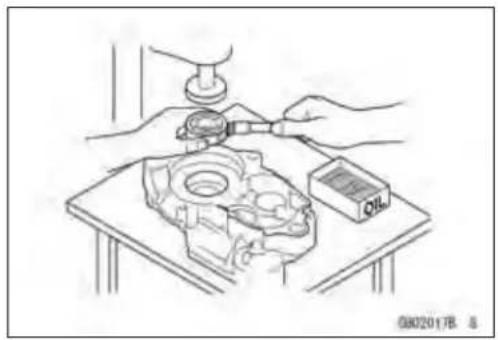
Foritemssuchasbearingsoroilsealsthatmustbe pressedintoplace,applysmallamountofoiltothecontactarea.Besuretomaintainproperalignmentanduse smoothmovementswheninstalling.
BallBearingandNeedleBearing
Donotremovepressedballorneedleunlessremovalis absolutelynecessary.Replacewithnewoneswhenever removed.Pressbearingswiththemanufacturerandsize marksfacingout.Pressthebearingintoplacebyputting pressureonthecorrectbearingraceasshown.
Pressingtheincorrectracecancausepressurebetween theinnerandouterraceandresultinbearingdamage.
OilSeal, GreaseSeal
Donotremovepressedoilorgreasesealsunlessremoval isnecessary.Replacewithnewoneswheneverremoved. Pressnewoilsealswithmanufactureandsizemarksfacing out.Makesurethesealisalignedproperlywheninstalling.
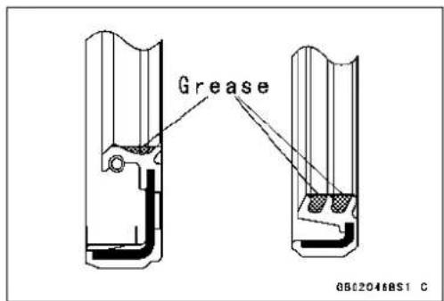
Applyspecifiedgreasetothelipofsealbeforeinstalling theseal.
Circlips, CotterPins
Replacecirclipsorcotterpinsthatwereremovedwithnew ones. Takecarenottoopentheclipexcessivelywheninstallingtopreventdeformation.
natural_image
Technical line drawing of a mechanical assembly with hands and a small component (no text or symbols)
natural_image
Technical drawing of a mechanical assembly with two views showing a bearing and a circular component (no text or symbols)

natural_image
Line drawing of a hand holding a tool with a pen, next to a cylindrical object (no text or symbols)1-6GENERALINFORMATION
BeforeServicing
Lubrication
Itisimportanttolubricaterotatingorslidingpartsduring assemblytominimizewearduringinitialoperation.Lubricationpointsarecalledoutthroughoutthismanual,apply thespecificoilorgreaseasspecified.
DirectionofEngineRotation
Whenrotatingthecrankshaftbyhand, thefreeplay amountofrotatingdirectionwillaffecttheadjustment. Rotatethecrankshafttopositivedirection(clockwiseviewed fromoutputside).
ElectricalWires
Atwo-colorwireisidentifiedfirstbytheprimarycolorand thenthestripecolor.Unlessinstructedotherwise,electrical wiresmustbeconnectedtothoseofthesamecolor.
Instrument
Useameterthathasenoughaccuracyforanaccurate measurement.Readthemanufacture'sinstructionsthor- oughlybeforeusingthemeter.Incorrectvaluesmaylead toimproperadjustments.

natural_image
Line drawing of hands using a tool to lift a tire (no text or symbols)
natural_image
Line drawing of a mechanical component with a lever and adjustment arrow (no text or symbols)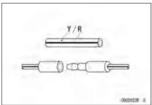

natural_image
Line drawing of a hand using a multimeter to test electrical components (no text or symbols present)ModelIdentification
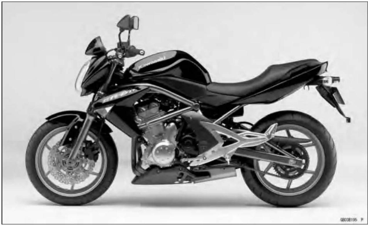
ER650A6F/ER650A6SLeftSideView
natural_image
Side profile of a black motorcycle with visible engine and front wheel (no text or symbols)ER650A6F/ER650A6SRightSideView

natural_image
Side profile of a black motorcycle with visible engine and wheel (no text or symbols)ER650A6F:Australia,Malaysia
ER650A6S:Europe
GeneralSpecifications
| ItemsER650A6F/ER650A6S | |
| Dimensions | |
| OverallLength2100mm(82.7in.) | |
| OverallWidth760mm(29.9in.) | |
| OverallHeight1095mm(43.1in.) | |
| Wheelbase1405mm(55.3in.) | |
| RoadClearance140mm(5.5in.) | |
| SeatHeight785mm(30.9in.) | |
| DryMass174kg(383.7lb) | |
| CurbMass: | |
| Front | 98kg(216.1lb) |
| Rear98kg(216.1lb) | |
| FuelTankCapacity15.5L(4.1USgal.) | |
| Performance | |
| MinimumTurningRadius | 2.7m(8.9ft) |
| Engine | |
| Type | 4-stroke, DOHC, 2-cylinder |
| CoolingSystem | Liquid-cooled |
| BoreandStroke | 83×60mm(3.3×2.4in.) |
| Displacement | 649cm3(39.60cuin.) |
| Compression Ratio | 11.3 : 1 |
| Maximum Horsepower | 53 kW (72 PS) @8 500 r/min (rpm), |
| Maximum Torque | 66 N·m (6.7 kgf·m, 49 ft·lb) @7 000 r/min (rpm), |
| Carburetion System | FI (Fuel Injection) KEIHIN TTK38 × 2 |
| StartingSystem | Electricstarter |
| Ignition System | Battery and coil (transistorized) |
| Timing Advance | Electronically advanced(digitaligniter) |
| IgnitionTiming | From 10° BTDC @1 300 r/min (rpm) to 35° BTDC @4 800 r/min(rpm) |
| SparkPlug | NGKCR9EIA-9 |
| Cylinder Numbering Method | Left to right, 1-2 |
| FiringOrder | 1-2 |
| ValveTiming: | |
| Inlet: | |
| Open | 31°BTDC |
| Close | 61°ABDC |
| Duration | 272° |
| Exhaust: | |
| Open | 50°BBDC |
| Close | 30°ATDC |
| Duration | 260° |
| Lubrication System | Forced lubrication (semi-dry sump) |
| EngineOil: | |
| Type | APISE,SForSG |
| APISH,SJor SLwithJASOMA | |
GeneralSpecifications
| ItemsER650A6F/ER650A6S | |
| ViscositySAE10W-40Capacity2.4L(2.5USqt) | |
| DriveTrainPrimaryReductionSystem:TypeGearReductionRatio2.095(88/42)ClutchTypeTransmission:Type6-speed,constantmesh,returnshiftGearRatios:1st2nd1.714(36/21)3rd1.333(32/24)4th1.111(30/27)5th0.966(28/29)6thFinalDriveSystem:TypeChaindriveReductionRatio3.067(46/15)OverallDriveRatio 5.473@Topgear | |
| FrameTypeCaster(RakeAngle)TrailFrontTire:TypeTubelessSizeRimSizeRearTire:TypeTubelessSizeRimSizeFrontSuspension:TypeWheelTravelRearSuspension:TypeSwingarmWheelTravelBrakeType:FrontRear | Tubular,diamond24.5°102 mm (4.0 in.)120/70ZR17M/C(58W)17×3.50160/60ZR17M/C(69W)17×4.50Telescopicfork120mm(4.7in.)125mm(4.9in.)Dual discsSingledisc |
| ElectricalEquipmentBattery | 12V10Ah |
1-10GENERALINFORMATION
GeneralSpecifications
| ItemsER650A6F/ER650A6S | |
| Headlight:TypeSemi-sealedbeamBulb1 2 V 5 5 W × 2 / 5 5 W ( Hi / Lo )Tail/BrakeLight12V5/21WAlternator:TypeThree-phaseACRatedOutput24A/14V@5000r/min(rpm) | |
Specificationsaresubjecttochangewithoutnotice, and may not apply to every country.
TechnicalInformation-CassetteTypeTransmission
CassetteTypeTransmission
The transmission of the current model is unable to be removed without disassembling upper and lower crank case halves.
TheER650Aenablestransmissiontoberemovedfromtherightsideofengineasanassy, without disassemblingcrankcasehalves(seeTransmissionAssyRemovalintheCrankshaft/Transmission chapter).
TransmissionAssy: DriveShaft[A] OutputShaft[B] ShiftRods[C] ShiftDram[D] ShiftForks[E] TransmissionCase[F]


natural_image
Detailed cutaway view of a mechanical transmission assembly (no visible text or labels)1-12GENERALINFORMATION
TechnicalInformation-InletAirPressureSensor
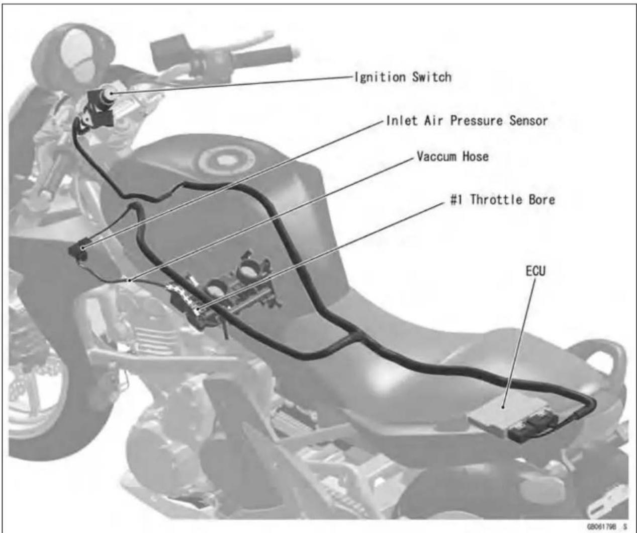
AtmosphericpressuresensorandcamshaftpositionsensorarenotequippedwiththeER650A.As asubstituteofthesesensorsabove,theER650Arecognizesatmosphericpressureandintakestroke of#1bythesignalofinletairpressuresensor.
The ECU detects atmospheric pressure when the ignition is switched ON. While the engine is running, the ECU also presumes atmospheric pressure by analyzing the waveform of boost pressure over fixed period. The intake stroke is recognized by waveform of boost pressure, therefore the system can recognize difference of each stroke.
UnitConversionTable
PrefixesforUnits:
| PrefixSymbolPower | ||
| megaM×1 kilok×1000 centic×0 millim×0.001 microμ×0.000001 | 0 0 0 0 0 0 . 0 1 0 1 000001 | |
UnitsofMass:
| kg | × | 2.205 | = | lb |
| g | × | 0.03527 | = | oz |
UnitsofVolume:
| L | × | 0.2642 | = | gal(US) |
| L | × | 0.2200 | = | gal (imp) |
| L | × | 1.057 | = | qt (US) |
| L | × | 0.8799 | = | qt (imp) |
| L | × | 2.113 | = | pint (US) |
| L | × | 1.816 | = | pint (imp) |
| mL | × | 0.03381 | = | oz (US) |
| mL | × | 0.02816 | = | oz (imp) |
| mL | × | 0.06102 | = | cu in |
UnitsofForce:
| N | × | 0.1020 | = | kg |
| N | × | 0.2248 | = | lb |
| kg | × | 9.807 | = | N |
| kg | × | 2.205 | = | lb |
UnitsofLength:
| km | × | 0.6214 | = | mile |
| m | × | 3.281 | = | ft |
| mm | × | 0.03937 | = | in |
UnitsofTorque:
| N·m | × | 0.1020 | = | kgf·m |
| N·m | × | 0.7376 | = | ft·lb |
| N·m | × | 8.851 | = | in·lb |
| kgf·m | × | 9.807 | = | N·m |
| kgf·m | × | 7.233 | = | ft·lb |
| kgf·m | × | 86.80 | = | in·lb |
UnitsofPressure:
| kPax | 0.01020 | = | kgf/cm2 | |
| kPax | 0.1450 | = | psi | |
| kPax | 0.7501 | = | cmHg | |
| kgf/cm2 | × | 98.07 | = | kPa |
| kgf/cm2 | × | 14.22 | = | psi |
| cmHg | × | 1.333 | = | kPa |
UnitsofSpeed:
| km/h | × | 0.6214 | = | mph |
UnitsofPower:
| kW | × | 1.360 | = | PS |
| kW | × | 1.341 | = | HP |
| PS | × | 0.7355 | = | kW |
| PS | × | 0.9863 | = | HP |
UnitsofTemperature:

line
| Position | Value | |---|---| | -40 | -20 | | -20 | -17.8 | | -4 | 0 | | 20 | 32 | | 40 | 4.4 | | 60 | 68 | | 80 | 80 | | 100 | 104 | | 120 | 120 | | 140 | 140 | | 160 | 160 | | 176 | 176 | | 180 | 180 | | 200 | 200 | | 220 | 220 | | 248 | 248 | | 260 | 260 | | 284 | 284 | | 300 | 300 | | 320 | 320 |PeriodicMaintenance
TableofContents
Periodic Maintenance Chart 2-3
Torque and Locking Agent.... 2-6
Specifications 2-11
Special Tools 2-13
Periodic Maintenance Procedures.... 2-14
Fuel System (DFI) 2-14
FuelHoseInspection(fuelleak,damage,installationcondition)....2-14
Throttle Control System Inspection.... 2-14
Idle Speed Inspection 2-15
Idle Speed Adjustment.... 2-15
Air Cleaner Element Cleaning.... 2-16
EngineVacuumSynchronizationInspection....2-17
Cooling System.... 2-19
Coolant Level Inspection.... 2-19
RadiatorHoseandPipeInspection(coolantleak,damage,installationcondition)......2-20
Air Suction System 2-20
AirSuctionSystemDamageInspection....2-20
Engine Top End 2-20
Valve Clearance Inspection 2-20
Valve Clearance Adjustment.... 2-22
Clutch 2-25
Clutch Operation Inspection.... 2-25
Wheels/Tires 2-25
Air Pressure Inspection.... 2-25
Wheel/Tire Damage Inspection 2-26
Tire Tread Wear, Abnormal Wear Inspection 2-26
WheelBearingDamageInspection 2-27
Drive Train 2-27
Drive Chain Lubrication Condition Inspection 2-27
Drive Chain Slack Inspection 2-28
Drive Chain Slack Adjustment 2-28
Wheel Alignment Inspection 2-29
Drive Chain Wear Inspection 2-30
Chain Guide Inspection.... 2-30
Brake System 2-31
BrakeFluidLeak(BrakeHoseandPipe)Inspection....2-31
Brake Hose Damage and Installation Condition Inspection 2-31
Brake Operation Inspection 2-31
Brake Fluid Level Inspection 2-32
Brake Pad Wear Inspection 2-33
BrakeLightSwitchOperationInspection....2-33
Suspensions 2-34
FrontForks/RearShockAbsorberOperationInspection....2-34
Front Fork Oil Leak Inspection 2-34
Rear Shock Absorber Oil Leak Inspection 2-34
Steering System 2-35
Steering Play Inspection 2-35
Steering Play Adjustment.... 2-35
Steering Stem Bearing Lubrication 2-36
Electrical System 2-37
Spark Plug Condition Inspection 2-37
LightsandSwitchesOperationInspection......2-38
Headlight Aiming Inspection 2-40
SidestandSwitchOperationInspection 2-41
EngineStopSwitchOperationInspection......2-42
Others 2-43
Chassis Parts Lubrication 2-43
Bolts,NutsandFastenersTightnessInspection......2-44
Replacement Parts 2-45
AirCleanerElementReplacement....2-45
Engine Oil Change 2-45
Oil Filter Replacement 2-46
Fuel Hose Replacement 2-46
Coolant Change 2-47
RadiatorHoseandO-ringReplacement....2-50
BrakeHoseandPipeReplacement....2-51
Brake Fluid Change 2-51
MasterCylinderRubberPartsReplacement....2-53
CaliperRubberPartsReplacement....2-54
Spark Plug Replacement 2-56
PeriodicMaintenanceChart
Thescheduledmaintenancemustbedoneinaccordancewiththischarttokeepthemotorcyclein goodrunningcondition. Theinitialmaintenanceisvitallyimportantandmustnotbeneglected.
PeriodicInspection
| FREQUENCY | Whichever comes first ↓ Every | *ODOMETERREADING ×1000km (×1000mile) | See Page | ||||||
| 161(0.6) | 2182(4) | 4303(7.5) | 6(12) | (15) | (20) | (24) | |||
| INSPECTION | |||||||||
| Fuel System | |||||||||
| Aircleanerelement -clean | ● | ● | ● | 2-16 | |||||
| Throttle control system (play, smooth return,no drag)- inspect | year | ● | ● | ● | ● | 2-14 | |||
| Enginevacuumsynchronization-inspect | ● | ● | ● | 2-17 | |||||
| Idlespeed - inspect | ● | ● | ● | ● | 2-15 | ||||
| Fuelleak(fuelhoseandpipe)-inspect year | ● | ● | ● | ● | 2-14 | ||||
| Fuelhoseandpipedamage-inspect year | ● | ● | ● | ● | 2-14 | ||||
| Fuelhose andpipe installationcondition - inspect | year | ● | ● | ● | ● | 2-14 | |||
| CoolingSystem | |||||||||
| Coolantlevel -inspect | ● | ● | ● | ● | 2-19 | ||||
| Coolant leak (radiator hose and pipe) - inspect | year | ● | ● | ● | ● | 2-20 | |||
| Radiatorhosedamage-inspect | year | ● | ● | ● | ● | 2-20 | |||
| Radiator hose installation condition - inspect | year | ● | ● | ● | ● | 2-20 | |||
| AirSuction System | |||||||||
| Airsuctionsystemdamage-inspect | ● | ● | ● | 2-20 | |||||
| EngineTop End | |||||||||
| Valve clearance - inspect | Every 42 000 km (26 000 mile) | 2-20 | |||||||
| Clutch | |||||||||
| Clutch operation( play, disengagement, engagement)- inspect | ● | ● | ● | ● | 2-25 | ||||
| Wheels andTires | |||||||||
| Tire air pressure - inspect | year | ● | ● | ● | 2-25 | ||||
| Wheel/tiredamage-inspect | ● | ● | ● | 2-26 | |||||
| Tiretreadwear,abnormalwear-inspect | ● | ● | ● | 2-26 | |||||
| Wheelbearingdamage-inspect | year | ● | ● | ● | 2-27 | ||||
| Drive Train | |||||||||
| Drive chain lubrication condition - inspect # | Every 600 km (400 mile) | 2-27 | |||||||
| Drive chain slack - inspect # | Every 1 000 km (600 mile) | 2-28 | |||||||
| Drivechainwear -inspect# | ● | ● | ● | 2-30 | |||||
| Chainguidewear -inspect | ● | ● | ● | 2-30 | |||||
| Brake System | |||||||||
| Brake fluid leak (brake hose and pipe) - inspect | year | ● | ● | ● | ● | ● | ● | ● | 2-31 |
2-4 PERIODIC MAINTENANCE
PeriodicMaintenanceChart
| FREQUENCY | Whichever comes first ↓ Every | *ODOMETERREADING × 1000k (×1000mile) | m See Page | ||||||
| 161(0.6) | 2182(4) | 4303(7.5) | 6(12) | (15) | (20) | (24) | |||
| INSPECTION | |||||||||
| Brakehoseandpipedamage-inspectyear | ●● | ●●●● | ● | 2-31 | |||||
| Brakehoseinstallationcondition-inspect | year | ●● | ●●●● | ● | 2-31 | ||||
| Brakeoperation(effectiveness,play,no drag)-inspect | year | ●● | ●●●● | ● | 2-31 | ||||
| Brakefluidlevel-inspect | 6 months | ●● | ●●●● | ● | 2-32 | ||||
| Brakepadwear-inspect# | ●●●●● | ● | 2-33 | ||||||
| Brakelightswitchoperation-inspect | ●● | ●●●● | ● | 2-33 | |||||
| Suspensions | |||||||||
| Frontforks/rearshockabsorberoperation (dampingandsmoothstroke)-inspect | ● | ● | ● | 2-34 | |||||
| Frontforks/rearshockabsorberoilleak-inspect | year | ● | ● | ● | 2-34 | ||||
| SteeringSystem | |||||||||
| Steeringplay-inspect | year | ● | ● | ● | ● | 2-35 | |||
| Steering stem bearings - lubricate | 2 years | ● | 2-36 | ||||||
| ElectricalSystem | |||||||||
| Sparkplugcondition-inspect | ● | ● | ● | 2-37 | |||||
| Lightsandswitchesoperation-inspect | year | ● | ● | ● | 2-38 | ||||
| Headlightaiming-inspect | year | ● | ● | ● | 2-40 | ||||
| Sidestandswitchoperation-inspect | year | ● | ● | ● | 2-41 | ||||
| Enginestopswitchoperation-inspect | year | ● | ● | ● | 2-42 | ||||
| Others | |||||||||
| Chassisparts-lubricate | year | ● | ● | ● | 2-43 | ||||
| Boltsandnutstightness-inspect | ● | ● | ● | ● | 2-44 | ||||
: Service more frequently when operating in severe conditions; dusty, wet, muddy, high speed or frequent starting/stopping.
*: Forhigherodometerreadings,repeatatthefrequencyintervalestablishedhere.
PeriodicMaintenanceChart
PeriodicReplacementParts
| CHANGE/REPLACE ITEM | FREQUENCY Whichever comes first ↓ Every | *ODOMETERREADING ×1000km (×1000mile) | See Page | ||||
| 112(0.6) | 243648(7.5) | (15) | (24) | (30) | |||
| Aircleanerelement#2years2-45 | |||||||
| Engineoil# | year | ● | ● | ● | ● | ● | 2-45 |
| Oilfilter | year | ● | ● | ● | ● | ● | 2-46 |
| Fuelhose | 4years | ● | 2-46 | ||||
| Coolant | 3years | ● | 2-47 | ||||
| RadiatorhoseandO-ring | 3years | ● | 2-50 | ||||
| Brakehoseandpipe | 4years | ● | 2-51 | ||||
| Brakefluid | 2years | ● | ● | 2-51 | |||
| Rubber parts of master cylinder and caliper | 4 years | ● | 2-53 | ||||
| Sparkplug | ● | ● | ● | ● | 2-56 | ||
: Service more frequently when operating in severe conditions; dusty, wet, muddy, high speed or frequent starting/stopping.
*: For higher odometer readings, repeat at the frequency interval established here.
TorqueandLockingAgent
The following tables list the tightening torque for them major fasteners requiring use of a non-permanent locking agentor liquid gasket.
Lettersusedinthe"Remarks"columnmean:
AL: Tightenthewoclampboltsalternatelytwotimestoensureeventighteningtorque.
EO:Applyengineoil.
L: Applyanon-permanentlockingagenttothethreads.
Lh:Left-handthreads
MO:Applymolybdenumdisulfideoilsolution.
R:ReplacementParts
S: Tightenthefastenersfollowingthespecifiedsequence.
Si:Applysiliconegrease(ex.PBCgrease).
SS:Applysiliconesealant.
| Fastener | Torque | Remarks | ||
| N·mkgf | mft·lb | |||
| FuelSystem | ||||
| WaterTemperatureSensor121.2106in·lb | ||||
| SpeedSensorBolt7.8 0.8069in·lb | L | |||
| Fuel Pump Bolts | 9.8 | 1.0 | 87 in·lb | L, S |
| OxygenSensor | 44.1 | 4.50 | 32.5 | |
| CoolingSystem | ||||
| Radiator Hose Clamp Screws | 2.0 | 0.20 | 17 in·lb | |
| Water Pump Impeller Bolt | 9.8 | 1.0 | 87 in·lb | |
| Water Pump Cover Bolts | 9.8 | 1.0 | 87 in·lb | |
| Water Pump Drain Bolt | 7.0 | 0.70 | 62 in·lb | |
| Thermostat Housing Bolts | 9.8 | 1.0 | 87 in·lb | |
| WaterTemperatureSensor121.2106in·lb | ||||
| EngineTopEnd | ||||
| Air Suction Valve Cover Bolts | 9.8 | 1.0 | 87 in·lb | |
| Cylinder Head Cover Bolts | 9.8 | 1.0 | 87 in·lb | |
| Camshaft Cap Bolts | 12 | 1.2 | 106 in·lb | S |
| CylinderHeadBolts(M10NewBolts) | 545.5 | 40 | MO,S | |
| Cylinder Head Bolts (M10 Used Bolts) | 49 | 5.0 | 36 | MO, S |
| Cylinder Bolt (M8) | 27.5 | 2.8 | 20 | MO, S |
| Cylinder Nut (M10) | 49 | 5.0 | 36 | MO, S |
| Cylinder Head Bolts (M6) | 12 | 1.2 | 106 in·lb | S |
| Cylinder Bolts (M6) | 12 | 1.2 | 106 in·lb | S |
| Throttle Body Holder Bolts | 12 | 1.2 | 106 in·lb | |
| Rear Camshaft Chain Guide Bolt | 20 | 2.0 | 15 | L |
| Camshaft Chain Tensioner Mounting Bolts | 9.8 | 1.0 | 87 in·lb | |
| CamshaftChainTensionerCapBolt | 202.0 | 15 | ||
| Camshaft Sprocket Bolts | 15 | 1.5 | 11 | L |
| Spark Plugs | 15 | 1.5 | 11 | |
| Exhaust Pipe Manifold Holder Nuts | 17 | 1.7 | 12 | |
| Muffler Body Mounting Bolt (Front) | 20 | 2.0 | 15 | |
| Muffler Body Mounting Bolt (Rear) | 20 | 2.0 | 15 | |
| BafflePlateBolts | 5.9 | 0.6052in·lb | ||
TorqueandLockingAgent
| Fastener | Torque | Remarks | ||
| N·mkgf | mft·lb | |||
| Clutch | ||||
| UpperCaponClutchCover3.90.4035in·lb | Hand-tighten | |||
| LowerCaponClutchCover | — | |||
| OilFillerPlug—Hand-tighten | ||||
| ClutchCoverMountingBolts9.81.087in·lb | ||||
| ClutchSpringBolts | 9.81.087 | in·lb | ||
| ClutchHubNut | 132 | 13.5 | 98 | R |
| Clutch Lever Clamp Bolts | 7.8 | 0.80 | 69 in·lb | S |
| Oil Pump Chain Guide Bolts | 12 | 1.2 | 106 in·lb | L |
| Clutch Cable Holder Bolts | 9.8 | 1.0 | 87 in·lb | L |
| ClutchCableClampBolt | 9.81.087 | in·lb | ||
| EngineLubrication | ||||
| Engine Oil Drain Bolt | 20 | 2.0 | 15 | |
| Filter Plate Bolt | 9.8 | 1.0 | 87 in·lb | L |
| Oil Filter | 17.2 | 1.75 | 13 | EO, R |
| Holder Mounting Bolt | 25 | 2.5 | 18 | L |
| Oil Pan Bolts | 12 | 1.2 | 106 in·lb | |
| OilPipeBolts | 9.81.087 | in·lb | ||
| Oil Pipe Plate Bolt | 9.8 | 1.0 | 87 in·lb | L |
| Oil Pressure Relief Valve | 15 | 1.5 | 11 | L |
| Oil Pressure Switch | 15 | 1.5 | 11 | SS |
| OilPumpCoverBolts | 9.81.087 | in·lb | L | |
| Oil Pump Sprocket Bolt | 12 | 1.2 | 106 in·lb | L, Lh |
| Oil Passage Plug | 20 | 2.0 | 15 | L |
| Oil Plate Bolts | 9.8 | 1.0 | 89 in·lb | L |
| EngineRemoval/Installation | ||||
| Engine Mounting Bracket Bolts | 25 | 2.5 | 18 | |
| Front Engine Mounting Bolts | 44 | 4.5 | 32 | |
| Rear Engine Mounting Nuts | 44 | 4.5 | 32 | |
| Crankshaft/Transmission | ||||
| OilPlateBolts | 9.81.087 | in·lb | L | |
| BreatherPlateBolts | 9.81.087 | in·lb | L | |
| Crankcase Bolts (M9, L = 113 mm) | 44 | 4.5 | 32 | MO, S |
| CrankcaseBolts(M9,L=83 mm) | 44 | 4.5 | 32 | MO,S |
| Crankcase Bolts (M8, L = 73 mm) | 35 | 3.6 | 26 | MO, S |
| Crankcase Bolts (M8, L = 60 mm) | 35 | 3.6 | 26 | MO, S |
| Crankcase Bolts (M8, L = 110 mm) | 27.5 | 2.8 | 20 | S |
| Crankcase Bolts (M8, L = 50 mm) | 27.5 | 2.8 | 20 | S |
| Crankcase Bolts (M6) | 19.6 | 2.0 | 15 | S |
| UpperCrankcaseBolts | 27.52.8 | 20 | S | |
| Shift Drum Bearing Holder Screw | 4.9 | 0.50 | 43 in·lb | L |
| Connecting Rod Big End Nuts | see Text | ← | ← | ← |
| Timing Rotor Bolt | 40 | 4.1 | 30 | |
TorqueandLockingAgent
| Fastener | Torque | Remarks | ||
| N·mkgf | mft·lb | |||
| OilPressureSwitch | 151.511 | SS | ||
| OilPassagePlug202.015L | ||||
| Gear Positioning Lever Bolt | 12 | 1.2 | 106 in·lb | L |
| ShiftShaftReturnSpringpin292.922L | ||||
| Shift Drum Cam Bolt | 12 | 1.2 | 106 in·lb | L |
| NeutralSwitch | 151.511 | |||
| TransmissionCaseBolts | 202.015 | |||
| Shift Rod Plate Bolt | 9.8 | 1.0 | 87 in·lb | |
| Neutral Switch Holder Screw | 4.9 | 0.50 | 43 in·lb | L |
| Shift Shaft Cover Bolts | 9.8 | 1.0 | 87 in·lb | L (see Text) |
| Shift Shaft Cover Screw | 4.9 | 0.50 | 43 in·lb | L |
| Wheels/Tires | ||||
| Front Axle | 108 | 11.0 | 80 | |
| FrontAxleClampBolt | 343.525 | |||
| Rear Axle Nut | 108 | 11.0 | 80 | |
| FinalDrive | ||||
| Engine Sprocket Nut | 125 | 12.7 | 92 | MO |
| Rear Axle Nut | 108 | 11.0 | 80 | |
| RearSprocketNuts | 596.044 | |||
| Speed Sensor Bolt | 7.8 | 0.80 | 69 in·lb | L |
| Speed Sensor Bracket Bolts | 9.8 | 1.0 | 87 in·lb | |
| Brakes | ||||
| Bleed Valve | 7.8 | 0.80 | 69 in·lb | |
| Brake Hose Banjo Bolts | 25 | 2.5 | 18 | |
| Brake Lever Pivot Bolt | 1.0 | 0.10 | 9 in·lb | Si |
| Brake Lever Pivot Bolt Locknut | 5.9 | 0.60 | 52 in·lb | |
| Brake Pedal Bolt | 8.8 | 0.90 | 78 in·lb | |
| Front Brake Disc Mounting Bolts | 27 | 2.8 | 20 | L |
| Front Brake Light Switch Screw | 1.0 | 0.10 | 9 in·lb | |
| Front Brake Reservoir Cap Screws | 1.0 | 0.10 | 9 in·lb | |
| Front CaliperMountingBolts | 343.525 | |||
| Front Master Cylinder Clamp Bolts | 8.8 | 0.90 | 78 in·lb | S |
| Rear Brake Disc Mounting Bolts | 27 | 2.8 | 20 | L |
| Rear CaliperMountingBolts | 252.518 | |||
| Rear Master Cylinder Mounting Bolts | 25 | 2.5 | 18 | |
| Rear Master Cylinder Push Rod Locknut | 18 | 1.8 | 13 | |
| Suspension | ||||
| FrontAxleClampBolt | 343.525 | |||
| Front Fork Bottom Allen Bolts | 30 | 3.1 | 22 | L |
| Front Fork Clamp Bolts (Lower) | 20 | 2.0 | 15 | AL |
| Front Fork Clamp Bolts (Upper) | 20 | 2.0 | 15 | |
| Front Fork Top Plugs | 25 | 2.5 | 18 | |
| RearShock AbsorberBolt | 596.044 | |||
TorqueandLockingAgent
| Fastener | Torque | Remarks | ||
| N·mkgf | mft·lb | |||
| RearShockAbsorberNut | 596.044 | |||
| SwingarmPivotShaftNut10811.080 | ||||
| Steering | ||||
| FrontForkClampBolts(Lower)202.015AL | ||||
| FrontForkClampBolts(Upper)202.015 | ||||
| Handlebar Holder Bolts | 25 | 2.5 | 18 | S |
| LeftSwitchHousingScrews | 3.5 | 0.36 | 31in·lb | |
| Right Switch Housing Screws | 3.5 | 0.36 | 31 in·lb | |
| SteeringStemHeadBolt | 10811.080 | |||
| Steering Stem Nut | 20 | 2.0 | 15 | |
| Frame | ||||
| FootpegStayBolts | 343.525 | |||
| Front Fender Bolts | 3.9 | 0.40 | 35 in·lb | |
| Front Fender Bracket Bolts | 8.8 | 0.90 | 78 in·lb | L |
| GrabRailMountingBolts | 252.518 | |||
| Lower Fairing Mounting Bolts | 8.8 | 0.90 | 78 in·lb | |
| SidestandBolt | 444.532 | |||
| Sidestand Switch Bolt | 8.8 | 0.90 | 78 in·lb | L |
| ElectricalSystem | ||||
| Alternator Cover Bolts | 9.8 | 1.0 | 87 in·lb | |
| Alternator Lead Holding Plate Bolt | 9.8 | 1.0 | 87 in·lb | L |
| Alternator Rotor Bolt | 155 | 15.8 | 114 | MO |
| Crankshaft Sensor Bolts | 6.0 | 0.60 | 53 in·lb | |
| Front Brake Light Switch Screw | 1.2 | 0.12 | 11 in·lb | |
| Left Switch Housing Screws | 3.5 | 0.36 | 31 in·lb | |
| License Plate Light Cover Screws | 0.90 | 0.090 | 8 in·lb | |
| License Plate Light Mounting Screws | 1.2 | 0.12 | 11 in·lb | |
| MeterScrews | 1.2 | 0.12 | 11in·lb | |
| Neutral Switch | 15 | 1.5 | 11 | |
| Oil Pressure Switch | 15 | 1.5 | 11 | SS |
| OxygenSensor | 44.1 | 4.5032.5 | ||
| Regulator/Rectifier Bolts | 8.8 | 0.90 | 78 in·lb | |
| Right Switch Housing Screws | 3.5 | 0.36 | 31 in·lb | |
| SidestandSwitchBolt | 8.8 | 0.90 | 78 in·lb | L |
| Spark Plugs | 15 | 1.5 | 11 | |
| Speed Sensor Bolt | 7.8 | 0.80 | 69 in·lb | L |
| Starter Motor Cable Terminal Nut | 6.0 | 0.60 | 53 in·lb | |
| Starter Motor Clutch Bolts | 34 | 3.5 | 25 | L |
| Starter Motor Mounting Bolts | 9.8 | 1.0 | 87 in·lb | L |
| StarterMotorTerminalLocknut | 11 | 1.1 | 97in·lb | |
| Starter Motor Through Bolts | 4.9 | 0.50 | 43 in·lb | |
| Stator Coil Bolts | 12 | 1.2 | 106 in·lb | L |
2-10 PERIODIC MAINTENANCE
TorqueandLockingAgent
| Fastener | Torque | Remarks | ||
| N·mkgf | mft·lb | |||
| TimingRotorBolt404.130WaterTemperatureSensor121.2106in·lb | ||||
Thetablebelow, relatingtighteningtorquetothreaddiameter, liststhebasictorquefortheboltsand nuts. Use histable for only the bolts and nuts which donot require as specific torque value. Allof the values are for use with dry solvent-cleaned threads.
BasicTorqueforGeneralFasteners
| ThreadsDiameter(mm) | Torque | ||
| N·mkgf·m | ft·lb | ||
| 5 | 3.4 ~ 4.9 | 0.35 ~ 0.50 | 30 ~ 43 in·lb |
| 6 | 5.9 ~ 7.8 | 0.60 ~ 0.80 | 52 ~ 69 in·lb |
| 8 | 14 ~ 19 | 1.4 ~ 1.9 | 10.0 ~ 13.5 |
| 10 | 25 ~ 34 | 2.6 ~ 3.5 | 19.0 ~ 25 |
| 12 | 44 ~ 61 | 4.5 ~ 6.2 | 33 ~ 45 |
| 14 | 73 ~ 98 | 7.4 ~ 10.0 | 54 ~ 72 |
| 16 | 115 ~ 155 | 11.5 ~ 16.0 | 83 ~ 115 |
| 18 | 165 ~ 225 | 17.0 ~ 23.0 | 125 ~ 165 |
| 20 | 225 ~ 325 | 23.0 ~ 33.0 | 165 ~ 240 |
Specifications
| ItemStandardServiceLimit | ||
| FuelSystemThrottle Grip Free PlayIdleSpeed1 300±50r/mBypass Screws (Turn Out)EngineVacuum35.3±1.3kPaAirCleanerElementPolyurethaneFoam- - - | - - - | |
| - - - | ||
| CoolingSystemCoolant:Type(recommended)ColorMixed RatioFreezingPointTotal Amount | Permanenttypeofantifreeze- - -GreenSoft water 50%, Coolant 50%-35°C(-31°F)1.2 L (1.3 US qt) | - - - |
| - - - | ||
| EngineTopEndValveClearance:ExhaustInlet | 0.22 ~ 0.31 mm (0.0087 ~ 0.0122 in.)0.15 ~ 0.21 mm (0.0059 ~ 0.0083 in.) | - - - |
| - - - | ||
| ClutchClutch Lever Free Play | 2 ~ 3 mm (0.08 ~ 0.12 in.) | - - - |
| EngineLubricationSystemEngineOil:TypeViscosityCapacityLevel | API SE, SF or SGAPISH,SJorSLwithJASOMASAE 10W-401.7 L (1.8 US qt) (when filter is not removed)1.9 L (2.0 US qt) (when filter is removed)2.4 L (2.5 US qt) (when engine is completelydry)Between upper and lower level lines(afteridlingorrunning) | - - - |
| - - - | ||
| - - - | ||
| - - - | ||
| - - - | ||
| - - - | ||
| Wheels/TiresTreadDepth:FrontRearAirPressure(whenCold):FrontRear | 6.5 mm (0.26 in.)9.0 mm (0.35 in.)Upto180kg(397lb)load:225kPa(2.25kgf/cm2,32psi)Upto180kg(397lb)load:250kPa(2.50kgf/cm2,36psi) | 1 mm (0.04 in.), (AT, CH,DE)1.6 mm (0.06 in.)Up to 130 km/h (80 mph):2 mm (0.08 in.),Over130km/h(80mph):3 mm (0.12in.) |
| - - - | ||
| - - - | ||
Specifications
| ItemStandardServiceLimit | ||
| FinalDrive | ||
| Drive Chain Slack | 30 ~ 40 mm (1.2 ~ 1.6 in.) | - - - |
| DriveChainWear(20-link Length) | 317.5 ~ 318.2 mm (12.50 ~ 12.53 in.) | 323 mm (12.7 in.) |
| StandardChain:MakeENUMA--TypeEK520MVXL1--Link114links | - - - | |
| Brakes | ||
| BrakeFluid:Grade | DOT4 | - - - |
| Brake Pad LiningThickness:Front | 4.5mm(0.18in.) | 1mm(0.04in.) |
| Rear | 5.0 mm (0.20 in.) | 1 mm (0.04 in.) |
| BrakeLightTiming:Front | PulledON | - - - |
| Rear | ONafterabout10mm(0.39in.) of pedaltravel | - - - |
| ElectricalSystem | ||
| Spark Plug Gap | 0.8 ~ 0.9 mm (0.03 ~ 0.04 in.) | - - - |
AT:Austria
CH: Switzerland
DE: Germany
SpecialTools
InsideCirclipPliers: 57001-143

natural_image
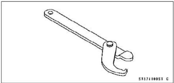
Line drawing of a pair of pliers (no text or symbols)SteeringStemNutWrench: 57001-1100
natural_image
Line drawing of a mechanical wrench tool (no text or symbols on the tool itself)Jack: 57001-1238

natural_image
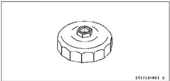
Technical line drawing of a mechanical support structure (no text or symbols)OilFilterWrench: 57001-1249
natural_image
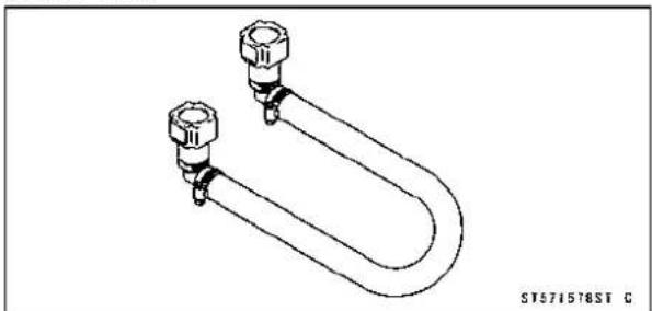
Technical line drawing of a mechanical knob or dial (no text or symbols)ExtensionTube: 57001-1578
natural_image
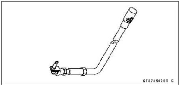
Technical line drawing of a U-shaped pipe fitting with two flanged ends (no text or symbols)PilotScrewAdjuster,E: 57001-1603
natural_image
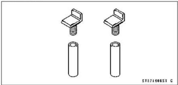
Technical line drawing of a pipe fitting with a bent end (no text or symbols)JackAttachment: 57001-1608
natural_image
Technical line drawing of two mechanical fasteners with cylindrical base (no text or symbols)2-14 PERIODIC MAINTENANCE
PeriodicMaintenanceProcedures
FuelSystem(DFI)
FuelHoseInspection(fuelleak,damage,installation condition)
The fuelhose is designed to be used throughout the motorcycle's lifewithout anymaintenance. However, if the motorcycle is not properly handled, the high pressure in-sidetheuelline can cause fuel to leak [A] or the hose to burst. Removetheueltank (see Fuel Tank Removal Fuel System (DFI) chapter) and check the fuel hose.
★Replacethefuelhoseifanyfraying, cracks[B]orbulges [C]arenotic.
- Check that the hosesarerouted according to Cable, Wire, and HoseRoutingsection in the Appendix chapter.
★Replacethehoseifithasbeensharplybentorkinked.
HoseJoints[A]
FuelHose[B]
- Check that the hose joints are securely connected.
○Pushandpull[A]thehosejoint[B]backandforthmore thantwotimes,andmakesureitislocked.
★ Ifitdoesnotlocked, reinstallthehosejoint.
WARNING
Makesurethehosejointisinstalledcorrectlyonthe deliverypipebyslidingthejoint,orthefuelcould leak.
ThrottleControlSystemInspection
-
Check that the throttle grip movess smoothly from full open to close [A], and the throttle closes quickly and completely by thereturnspring in all steering positions.
★ Ifthethrottlegripdoesn'treturnproperly, checkthethrottlecablerouting, gripfreeplay, andcabledamage. Then lubricatethrottlecable. -
Checkthethrottlegripfreeplay[A].
★Ifthefreeplayisincorrect,adjustthethrottlecable.
ThrottleGripFreePlay
Standard: 2 \~ 3 mm (0.08 \~ 0.12 in.)


natural_image
Close-up of a motorcycle handle and lever with a labeled component (A) and directional arrow, no readable text or symbols beyond the label.
natural_image
Close-up of a motorcycle handle and lever with a labeled component (A) and no visible text or symbols on the device itself.PeriodicMaintenanceProcedures
★ If necessary, adjust the throttleable as follows.
- Loosenthelocknut[A]attheupperendoftheaccelerator cable.
- Turntheadjuster[B]incompletelysoastogivethethrottle griplentyofplay.
- Loosenthelocknut[A]atthemiddleofthedecelerator cable.
- Turntheadjuster[B]untilthereisnoplaywhenthethrottle gripiscompletelyclosed.
- Tightenthelocknut.
- Turntheacceleratorcableadjusteruntiltheproper amountofthrottlegripfreeplayisobtained.
- Tightenthelocknut.
IdleSpeedInspection
- Starttheengineandwarmitupthoroughly.
- Withtheengineidling,turnthehandlebartobothsides [A].
★ Ifhandlebarmovementchangestheidlespeed, the throttlecablesmaybeimproperlyadjustedorincorrectly routedordamaged. Besuretocorrectanyofthese conditionsbeforeriding(seeThrottleControlSystem InspectionorCable,Wire,andHoseRoutingsectionin theAppendixchapter).
WARNING
Operationwithimproperlyadjusted, incorrectly routedordamagedcablescouldresultinanunsafe ridingcondition.
- Checkidlespeed.
★If the idle speed is out of the specified range, adjust it.
IdleSpeed
Standard: 1300±50r/min(rpm)
IdleSpeedAdjustment
- Starttheengineandwarmitupthoroughly.
- Turntheadjustingscrew[A]untiltheidlespeediscorrect.
Open and close the throttle a few times to make sure that theidlespeediswithinthespecifiedrange.Readjustif necessary.


natural_image
Close-up of a car's roof structure with two labeled points A and B (no text or symbols beyond labels)
natural_image
Close-up of a motorcycle's front wheel and side-mounted steering wheel (no visible text or symbols)
natural_image
Close-up of mechanical components with no visible text or symbols2-16PERIODICMAINTENANCE
PeriodicMaintenanceProcedures
AirCleanerElementCleaning
NOTE
○ Industryareas, theelementshouldbecleanedmore frequentlythantherecommendedinterval.
○ Afterridingthroughrainoronmuddilyroads, the elements should be cleaned immediately.
WARNING
Ifdirtordustisallowedtopassthroughintothe throttleassy,thethrottlemaybecomestuck,possiblycausingaccident.
CAUTION
Ifdirtgetsthroughintotheengine,excessiveenginewearandpossiblyenginedamagewillooccur.
- Removethefueltank(seeFuelTankRemovalintheFuel System(DFI)chapter).
- Remove: AirSwitchingValveHoseA AirCleanerElementScrew[B] AirCleanerElement[C]
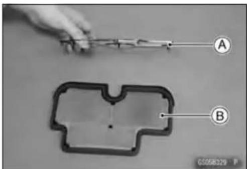
- Remove: UpperPlasticHolder[A] Element[B]

NOTE
○ Thewirescreen[A]isfastenedwithanadhesiveforthe shadedportion[B].Donotremovethewirescreen.

PeriodicMaintenanceProcedures
WARNING
Cleantheelementinawell-ventilatedarea,and makesurethattherearenosparksorflameany-whereneartheworkingarea. Becauseofthedangerofhighlyflammableliquids, donotusegasolineoralowflash-pointsolventto cleantheelement.
- Cleantheelement[A]inabathofhighflash-pointsolvent, andthendryitwithcompressedairorbyshakingit.
- Aftercleaning, saturateaclean, lint-freetowel with SE, SF, or SGclassSAE30oil and apply the oil to the element by tapping the element outsidewith the towel.
- Visuallychecktheelementfortearsorbreaks.
- Iftheelementhasanytearsorbreaks,replacetheelement.
- Installtheelementunit[A]withthefoamelementside(gray)[B]facingdown.

natural_image
Close-up of a plastic mechanical part with a labeled section A (no text or symbols beyond label)
EngineVacuumSynchronizationInspection
NOTE
These procedures are explained on the assumption that the inlet and exhaust system sof the engine are good condition.
- Situatethemotorcyclesothatitisvertical.
- Removethecenterfairing(seeCenterFairingRemoval intheFramechapter).
- Pullofftherubbercaps[A]fromthefittingofeachthrottle body(Inthephoto, thethrottlebodyhasbeenremoved forclarity).

CAUTION
Donotremovetheinletairpressuresensorhose [B]ontheleftfittingofthethrottlebody.
- Connectacommerciallyavailablevacuumgaugeand hoses[A]tothefittingsofthethrottlebodyasshown.
- Connectahighlyaccuratetachometertooneofthestick coilprimaryleads.
![KAWASAKI ER-6n (2006) - Donotremovetheinletairpressuresensorhose [B]ontheleftfittingofthethrottlebody. - 1](/content/2026/06/1277913/images/1ff43f97d6956e08a10671cf475e9d84694c6654505e1a287cd411fd64e97bf5.jpg)
natural_image
Technical line drawing of a mechanical assembly with gears and pipes (no text or symbols)2-18 PERIODIC MAINTENANCE
PeriodicMaintenanceProcedures
- Starttheengineandwarmitupthoroughly.
- Checktheidlespeed.
Tachometer[A] - Openandclosethethrottle.
★Iftheidlespeedisoutofthespecifiedrange,adjustit.
CAUTION
Donotmeasuretheidlespeedbythetachometerof themeterunit.
- Whileidlingtheengine, inspect the engine vacuum, using the vacuum gauge[B].
EngineVacuum
Standard:35.3±1.3kPa(265±10mmHg)atIdle
Speed1300±50r/min(rpm)
★Ifanyonevacuumisnotwithinthespecification,turnin thebypassscrewsuntilitseatsfullybutnottightly.
SpecialTool-PilotScrewAdjuster, E[A]:57001-1603
CAUTION
Donotovertightenthem. They could bedamaged, requiring replacement.
- Turnoutthebypassscrewofthehighervacuumbetween #1[A]and#2[B]tothelowervacuum.
- Openandclosethethrottlevalvesaftereachmeasurementandadjusttheidlespeedasnecessary.
- Inspectthevacuumsasbefore.
★Ifbothvacuumsarewithinthespecification,finishtheenginevacuumsynchronization.
★Ifanyvacuumcannotbeadjustedwithinthespecification, removethebypassscrews#1,#2andcleanthem.
- Removethebypassscrew[A], spring[B], washer[C] and O-ring[D].
○Checkthebypassscrewanditsholeforcarbondeposits.
★Ifanycarbonaccumulates,wipethecarbonoffthebypass screwandthehole,usingacottonpadpenetratedwith a high-flashpointsolvent.
○ReplacetheO-ringwithanewone.
○Checkthetaperedportion[E]ofthebypassscrewfor wearordamage.
★Ifthebypassscrewiswornordamaged,replaceit.
- Turninthebypassscrewuntilitseatsfullybutnottightly.


natural_image
Close-up of mechanical components with no visible text or symbols

PeriodicMaintenanceProcedures
- Repeatthesameprocedureforotherbypassscrews.
- Repeatthesynchronization.
★ If the vacuums are correct, check the output voltage of themainthrottlesensor (see Main Throttle Sensor Output Voltage Inspection in the Fuel System (DFI) chapter).
MainThrottleSensorOutputVoltage ConnectionstoECU
Meter(+)→ Y/Wlead(terminal7)
Meter(-)→ BR/BKlead(terminal28)
Standard:
1.055\~ 1.095VDC(atidlethrottleopening)
★ If the output voltage is out of the range, check the throttle input voltage (see Main Throttle Sensor Input Voltage Inspection in the Fuel System (DFI) chapter).
- Removethevacuumgaugehosesandinstallthevacuum hosesandrubbercaps.
CoolingSystem
CoolantLevelInspection
NOTE
○Checkthelevelwhentheengineiscold(roomorambienttemperature).
- Checkthecoolantlevelinthereservetank[A]withthe motorcycleheldperpendicular(Donotusethesidestand).
★ If the coolant level is slower than the "L" levelline[B], remove the right center fairing (see Center Fairing Removal in the Frame chapter) and unscrew the reservoir tank cap, and add coolant to the "F" levelline[C].
"L":low
"F":full
CAUTION
Forrefilling, addthespecifiedmixture of coolant and softwater. Adding water alonedilutesthe coolant and degrades its anticorrosion properties. Thediluted coolant can attack the aluminum engine parts. Inan emergency, softwater alone can be added. But the diluted coolant must be returned to the correct mixturerati within a few days. If coolant must be added often or thereservoir tank has run completely dry, there is probably leakage in the cooling system. Check the system for leaks. Cool an truinspainted surfaces. Immediately wash away any coolant that spills on the frame, engine, wheels or other painted parts.

2-20PERIODICMAINTENANCE
PeriodicMaintenanceProcedures
RadiatorHoseandPipeInspection(coolantleak, damage, installationcondition)
○Thehighpressureinsidetheradiatorhoseandpipecan causecoolanttoleak[A]orthehosetoburstifthelineis notproperlymaintained.
- Visuallyinspectthehosesforsignsofdeterioration. Squeezethehos. Ahoseshouldnotbehardand brittle, nor shouldditbesoftorswollen.
★Replacethehoseifanyfraying,cracks[B]orbulges[C]arenoticed.
- Check that the hoses are securely connected and clamps are tightened correctly.
Torque-RadiatorHoseClampScrews:2.0N·m(0.20kgf·m, 17in·lb)
AirSuctionSystem
AirSuctionSystemDamageInspection
- Removethefueltank(seeFuelTankRemovalintheFuel System(DFI)chapter).
- Removethefuelhose(seeFuelHoseReplacement).
- Connect:
FuelPumpLeadConnector[A] ExtensionTube[B]
Special Tool - Extension Tube: 57001-1578
- Pull the air switching valve hose [C] out of the air cleaner housing.
- Starttheengineandrunitatidlespeed.
- Plug[A]theairswitchingvalve hoseendwith yourfinger andfeelvacuumpulsinginthehose.
★Ifthereisnovacuumpulsation,checkthehoselinefor leak. If there is no leak, check the air switching valve (seeAirSwitchingValveUnitTestintheElectricalSystemchapter)orairsuctionvalve(seeAirSuctionValveInspectionintheEngineTopEndchapter).
EngineTopEnd
ValveClearanceInspection
NOTE
○ Valveclearancemustbecheckedandadjustedwhen theengineiscold(roomtemperature).
- Remove the cylinder head cover (see Cylinder Head CoverRemovalintheEngineTopEndchapter).
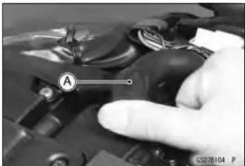
- Unscrewtheupper[A]andlower[B]capsontheclutch cover.


natural_image
Close-up of a gloved hand holding a component with a labeled section 'A' (no readable text or symbols beyond the label)
PeriodicMaintenanceProcedures
- CheckthevalveclearancewhenthepistonsareatTDC.
- Thepistonsarenumberedbeginningwiththeengineleft side.
- Usingawrench[A]onthecrankshaftrotationbolt,turn thecrankshaftclockwiseuntilthe"1|T"markonthetiming rotorisalignedwiththenotch[B]intheedgeoftheupper holeintheclutchcoverfor#1pistonand"2|T"markfor #2piston.
1|TMark[A]
2|TMark[B]
Hole[C]ofUpperCap
Notch[D]inEdgeofUpperHole


○Measurethevalveclearanceofthevalvesforwhichthe camareturnedawayfromeachother.

- Usingthethicknessgauge[A],measurethevalveclearancebetweencamandvalvelifter.
ValveClearance
Standard:
Exhaust 0.22 \~ 0.31 mm (0.0087 \~ 0.0122 in.)
Inlet 0.15 \~ 0.21 mm (0.0059 \~ 0.0083 in.)

natural_image
Close-up mechanical assembly with labeled component A (no readable text or symbols)○Eachpistonhastwoinletandtwoexhaustvalves.Measurethesetwoinletorexhaustvalvesatthesamecrankshaftposition.
ValveClearanceMeasuringPosition
1PistonTDCatEndofCompressionStroke→
Inletvalveclearancesof#1piston,and
Exhaustvalveclearancesof#1piston
NOTE
○Checkthevalveclearanceusingthismethodonly. Checkingtheclearanceatanyothercampositionmay resultinimpropervalveclearance.
ValveClearanceMeasuringPosition
2PistonTDCatEndofCompressionStroke→
Inletvalveclearancesof#2piston,and Exhaustvalveclearancesof#2piston
★ If the valve clearance is not within the specified range, first record the clearance, and adjust it.
ValveClearanceAdjustment
- Tochangethevalveclearance,removethecamshaft chaintensioner,camshaftsandvalvelifters.Replacethe shimwithoneofadifferentthickness.
NOTE
○ Markandrecordthevalvelifterandshimlocationsso theycanbereinstalledintheiroriginalpositions.
○ Ifthereisnoclearance,selectashimwhichisseveral sizesmallerandthenmeasuretheclearance.

Donotputshimstockundertheshim. This may cause the topopoutathighrpm, causing extensiveenginedamage. Donotgrindtheshim. This may cause it to fracture, causing extensiveenginedamage.
PeriodicMaintenanceProcedures
VALVECLEARANCEADJUSTMENTCHARTINLETVALVE
INLET
| PRESENT SHIM | |||||||||||||||||||||
| Part No. (92180) | 1014 | 1016 | 1018 | 1020 | 1022 | 1024 | 1026 | 1028 | 1030 | 1032 | 1034 | 1036 | 1038 | 1040 | 1042 | 1044 | 1046 | 1048 | 1050 | 1052 | 1054 |
| MARK | 50 | 55 | 60 | 65 | 70 | 75 | 80 | 85 | 90 | 95 | 00 | S | 10 | 15 | 20 | 25 | 30 | 35 | 40 | 45 | 50 |
| THICKNESS (mm) | 2.50 | 2.55 | 2.60 | 2.65 | 2.70 | 2.75 | 2.80 | 2.85 | 2.90 | 2.95 | 3.00 | 3.05 | 3.10 | 3.15 | 3.20 | 3.25 | 3.30 | 3.35 | 3.40 | 3.45 | 3.50 |

- Measure the clearance (when engine is cold).
- Checkpresentshimsize.
- Matchclearanceinverticalcolumnwithpresentshimsizeinhorizontalcolumn.
- Install the shim specified where the lines intersect. This shim will give the proper clearance.
Example: Presentshimis2.95mm
Measuredclearanceis0.45mm
Replace 2.95 mm shim with 3.20 mm shim.
- Remeasure the valve clearance and readjust if necessary.
VALVECLEARANCEADJUSTMENTCHARTEXHAUSTVALVE
EXHAUST
| PRESENT SHIM | Example | ||||||||||||||||||||
| Part No. (92180) | 1014 | 1016 | 1018 | 1029 | 1022 | 1024 | 1026 | 1028 | 1030 | 1032 | 1034 | 1036 | 1038 | 1040 | 1042 | 1044 | 1046 | 1048 | 1050 | 1052 | 1054 |
| MARK | 50 | 55 | 60 | 65 | 70 | 75 | 80 | 85 | 90 | 95 | 00 | 5 | 10 | 15 | 20 | 25 | 30 | 35 | 40 | 45 | 50 |
| THICKNESS (mm) | 2.50 | 2.55 | 2.60 | 2.65 | 2.70 | 2.75 | 2.80 | 2.85 | 2.90 | 2.95 | 3.00 | 3.05 | 3.10 | 3.15 | 3.20 | 3.25 | 3.30 | 3.35 | 3.40 | 3.45 | 3.50 |

- Measure the clearance (when engine is cold).
- Checkpresentshimsize.
- Matchclearanceinverticalcolumnwithpresentshimsizeinhorizontalcolumn.
- Install the shim specified where the lines intersect. This shim will give the proper clearance.
Example: Presentshimis2.95mm.
Measuredclearanceis0.47mm.
Replace 2.95 mm shim with 3.15 mm shim.
- Remeasure the valve clearance and readjust if necessary.
PeriodicMaintenanceProcedures
Clutch
ClutchOperationInspection
- Pulltheclutchleverjustenoughtotakeupthefreeplay [A].
- Measurethegapbetweentheleverandtheleverholder.
★Ifthegapistoowide,theclutchmaynotreleasefully.If thegapistoonarrow,theclutchmaynotengagefully.In eithercase,adjustit.
ClutchLeverFreePlay
Standard: 2 \~ 3 mm (0.08 \~ 0.12 in.)

natural_image
Close-up of a mechanical component with labeled parts (A) and no visible text or symbols beyond the label.WARNING
To avoid a serious burn, nevertouch the engine or exhaust pipe during clutch adjustment.
- Turn the adjuster [A] so that 5 \~ 6 mm (0.20 \~ 0.24 in.) [B] of threads are visible.

- Slidethedustcover[A]atthemiddleoftheclutchcable outofplace.
- Loosenthelocknut[B]atthemiddleofclutchcable.
- Turntheadjustingnut[C]untilthefreeplayiscorrect.

WARNING
Besurethattheoutercableendatheclutchlever isfullyseatedintheadjusterattheclutchlever,or itcouldslipintoplacelater,creatingenoughcable playtopreventclutchdisengagement.
- Aftertheadjustment, tightenthelocknutandstarttheengineandcheckthattheclutchdoesnotslipandthatit releasesproperly.
Wheels/Tires
AirPressureInspection
- Removetheairvalvecap.
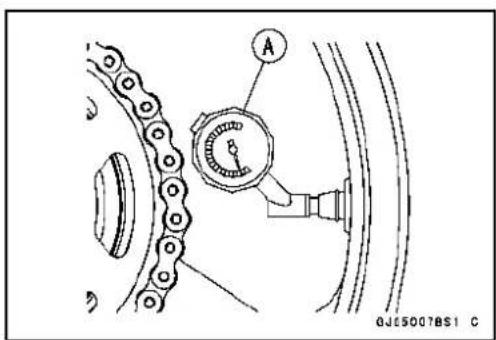
- Measure the air pressure with an air pressure gauge [A] when the tires are cold (thatis, when the motorcycle has not been ridden more than a mile during the past 3 hours).
• Installtheairvalvecap.
★Adjustthetireairpressureaccordingtothespecifications ifnecessary.
AirPressure(whenCold)
Front: Upto180kg(397lb) 225kPa(2.25kgf/cm²,32psi)
Rear: Upto180kg(397lb) 250kPa(2.50kgf/cm²,36psi)
PeriodicMaintenanceProcedures
Wheel/TireDamageInspection
- Removeanyimbeddedstones[A]orotherforeignparticles[B]fromtread.
- Visually inspect the tire for cracks and replace the tire if necessary. Swelling or high spots indicate internal damage, requiring tirereplacement.
- Visually inspect the wheelfor cracks, cuts and dents damage.
★Ifanydamageisfound, replacethewheelifnecessary.
TireTreadWear, AbnormalWearInspection
Asthetiretreadwearsdown, the tirebecomesmoresusceptibletopuncture and failure. An accepted estimate is that 90% of all tire failures occur during the last 10% of tread life (90% worn). So it is false economy and unsafetouse the tires until they are bald.
- Measurethetreaddepthatthecenterofthetreadwitha depthgauge[A].Sincethetiremaywearunevenly,take measurementatseveralplaces.
★Ifanymeasurementislessthantheservicelimit,replace thetire(seeTireRemoval/InstallationintheWheels/Tires chapter).


TreadDepth
Standard:
Front6.5mm(0.26in.)
Rear9.0mm(0.35in.)
ServiceLimit:
| Front | 1mm(0.04in.) (AT,CH,DE)1.6mm(0.06in.) |
| Rear | 2mm(0.08in.) (Upto130km/h(80mph)) 3mm(0.12in.) (Over130km/h(80mph)) |
WARNING
Toensuresafehandlingandstability,useonlythe recommended standard tires for replacement, inflatedtothestandardpressure.
NOTE
○ Mostcountriesmayhavetheirownregulationsamini-mumtiretreaddepth:besuretofollowthem.
○ Checkandbalancethewheelwhenatireisreplaced withanewone.
PeriodicMaintenanceProcedures
WheelBearingDamageInspection
- Raisethefrontwheeloffthegroundwithjack(seeFront WheelRemovalintheWheels/Tireschapter).
- Turnthehandlebarallthewaytotherightorleft.
- Inspecttheroughnessofthefrontwheelbearingbypushingandpulling[A]thewheel.
- Spin[B]thefrontwheellightly,andcheckforsmoothly turn,roughness,bindingornoise.
★ Ifroughness, bindingornoiseisfound, removethefront wheelandinspectthewheelbearing(seeFrontWheel Removal, HubBearingInspectionintheWheels/Tires chapter). - Raisetherearwheeloffthegroundwithstand(seeRear WheelRemovalintheWheels/Tireschapter).
- Inspecttheroughnessoftherearwheelbearingbypushingandpulling[A]thewheel.
- Spin[B]therearwheellightly,andcheckforsmoothly turn,roughness,bindingornoise.
★ Ifroughness, binding or noise is found, removetherear wheel and inspect the wheel bearing (see Rear Wheel Removal, Hub Bearing Inspection in the Wheels/Tires chapter) and coupling (see Coupling Bearing Inspection in the Final Drive chapter).


DriveTrain
DriveChainLubricationConditionInspection
- Ifaspeciallubricantisnotavailable, aheavyoilsuchas SAE90 is preferred to alighteroil because it will stay on the chain longer and provide better lubrication.
- If the chain appears especially dirty, clean it before lubrication.
CAUTION
TheO-ringsbetweenthesideplatessealinthelubricantbetweenthepinandthebushing.Toavoid damagingtheO-ringsandresultantlossoflubricant,observethefollowingrules.
UseonlykeroseneordieseloilforcleaninganO-ringdrivechain.Anyothercleaningsolutionsuch asgasolineortrichloroethylenewillcausedeteriorationandswellingoftheO-ring.Immediatelyblow thechaindrywithcompressedairaftercleaning. Completecleaninganddryingthechainwithin10 minutes.
2-28PERIODICMAINTENANCE
PeriodicMaintenanceProcedures
- Applyoiltothesidesoftherollerssothatoilwillpenetrate totherollersandbushings.ApplytheoiltotheO-ringsso thattheO-ringswillbecoatedwithoil.
- Wipeoffanyexcessoil. OilAppliedAreas[A] O-rings[B]
DriveChainSlackInspection
NOTE
○ Checktheslackwiththemotorcyclesettingonitssidestand.
○ Cleanthechainifitisdirty, and lubricateitifitappears dry.
- Checkthewheelalignment(seeWheelAlignmentInspection).
- Rotatetherearwheeltofindthepositionwherethechain istightest.
- Measure the vertical movement (chainslack) [A] midway between the prospects.
★Ifthechainslackexceedsthestandard,adjustit.
ChainSlack
Standard: 30 \~ 40 mm (1.2 \~ 1.6 in.)
DriveChainSlackAdjustment
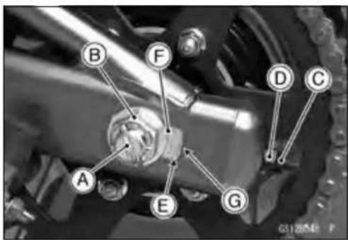
- Removethecotterpin[A], and loosentheaxlenut[B].
- Loosenthebothchainadjusterlocknuts[C].
★Ifthechainistooloose,turnintheleftandrightchain adjusternuts[D]evenly.
★Ifthechainistootight,turnouttheleftandrightchain adjusternutsevenly,andkickthewheelforward. - Turnbothchainadjusternutsevenlyuntilthedrivechain hasthecorrectamountofslack.Tokeepthechainand wheelproperlyaligned,thevalue[E]ontheleftwheel alignmentadjuster[F]shouldalignwiththesame(leftor right)edge[G]ofinspectionwindowontheswingarmthat therightwheelalignmentadjustervaluealignswith.
WARNING
Misalignmentofthewheelwillresultinabnormal wearandmayresultinanunsaferidingcondition.
- Tightenbothchainadjusterlocknutssecurely.
- Tightentheaxlenut.
- Turnthewheel, measure the chainslack again at the tightest position, and read just if necessary.
Torque-RearAxleNut:108N·m(11.0kgf·m,80ft·lb)


PeriodicMaintenanceProcedures
- Insertanewcotterpin[A].
NOTE
When inserting the cotterpin, if the slots in thenut do not align with the cotterpinhole in the axle, tighten the nut clockwise [B] uptonextalignment.
○Itshouldbewithin30°.
○Loosenonceandtightenagainwhentheslotgoespast thenaresthole.
- Bendthecotterpin[A]overthenut[B].
WARNING
Iftherearaxlenutisnotsecurelytightenedorthe cotterpinisnotinstalled,anunsaferidingconditionmayresult.


WheelAlignmentInspection
- Checkthatthevalue[A]ontheleftwheelalignmentadjuster[B]alignswiththesame(leftorright)edge[C]of inspectionwindowontheswingarmthattherightwheel alignmentadjustervaluealignswith.
★ Iftheydonot, adjust the chainslack and align the wheel alignment (seeDriveChainSlack Adjustment).
NOTE
○ Wheelalignmentcanbealsocheckedusingthe straightedgeorstringmethod.

WARNING
Misalignmentofthewheelwillresultinabnormal wear, and may result in an unsaferiding condition.
2-30 PERIODIC MAINTENANCE
PeriodicMaintenanceProcedures
DriveChainWearInspection
- Remove:
ChainCover(seeSwingarmRemovalintheSuspension chapter) - Rotatetherearwheeltoinspectthedrivechainfordamagedrollers, and loosepinsandlinks.
★Ifthereisanyirregularity, replacethedrivechain.
★Lubricatethedrivechainifitappearsdry. - Stretchthechaintautbyhanginga98N(10kg,20lb) weight[A]onthechain.
- Measurethelengthof20links[B]onthestraightpart[C]of thechainfromthepincenterofthe1stpintothepincenter ofthe21stpin.Sincethechainmaywearunevenly,take measurementsatseveralplaces.
★Ifanymeasurementsexceedtheservicelimit,replace the chain.Also,replacethefrontandrearsprocketswhenthe drivechainisreplaced.
DriveChain20-linkLength
Standard: 317.5 \~ 318.2 mm (12.50 \~ 12.53 in.)
ServiceLimit:323mm(12.7in.)
WARNING
Ifthedrivechainwearexceedstheservicelimit,re- placethechainoranunsaferidingconditionmay result.Achainthatbreaksorjumpsoffthesprock- etscouldsnagontheenginesprocketorlockthe rearwheel,severelydamagingthemotorcycleand causingittogooutofcontrol. Forsafely,useonlythestandardchain.Itisanend- lesstypeandshouldnotbecutforinstallation.
StandardChain
Make:ENUMA
Type: EK520MVXL1
Link: 114links
ChainGuideInspection
- Remove:
Swingarm(seeSwingarmRemovalintheSuspension chapter) - Visuallyinspectthechainguide[A].
★Replacethechainguideifitshowsanysignsofabnormal wearordamage.


natural_image
Close-up of a mechanical component with labeled section A (no readable text or symbols beyond label)PeriodicMaintenanceProcedures
BrakeSystem
BrakeFluidLeak(BrakeHoseandPipe)Inspection
- Applythebrakeleverorpedalandinspectthebrakefluid leakfromthebrakehoses[A]andfittings[B].
★ Ifthebrakefluidleakedfromanyposition,inspectorre-placetheproblempart.


BrakeHoseDamageandInstallationCondition Inspection
- Inspectthebrakehosesandfittingsfordeterioration, cracksandsignsofleakage.
○Thehighpressureinsidethebrakelinecancausefluidto leak[A]orthehosetoburstifthelineisnotproperlymaintained.Bendandtwisttherubberhosewhileexamining it.
★Replacethehoseifanycrack[B],bulge[C]orleakageis noticed.
★Tightenanybrakehosebanjobolts.
Torque-BrakeHoseBanjoBolts:25N·m(2.5kgf·m,18 ft·lb)
- Inspectthebrakehoserouting.
★Ifanybrakehoseroutingisincorrect, routethebrakehose accordingtoCable, Wire, and HoseRoutingsectioninthe Appendixchapter.

BrakeOperationInspection
- Inspecttheoperationofthefrontandrearbrakebyrunningthevehicleonthedryroad.
★ Ifthebrakeoperationisinsufficiency, inspectthebrake system.
WARNING
When inspecting by running the vehicle, notea surrounding traffic situation enough in the place of safety.
2-32PERIODICMAINTENANCE
PeriodicMaintenanceProcedures
BrakeFluidLevelInspection
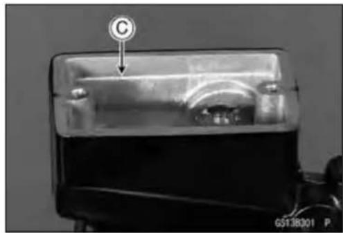
- Check that the brake fluid level in the front braker reservoir [A] is abovethelower levelline [B].
NOTE
○ Holdthereservoirhorizontalbyturningthehandlebar whencheckingbrakefluidlevel.
★Ifthefluidlevelislowerthanthelowerlevelline,fillthe reservoirtotheupperlevelline[C]inthereservoir.

- Removetheseat(seeSeatRemovalintheFramechapter).
- Check that the brake fluid level in therear braker reservoir [A] is abovethelower levelline[B].
★Ifthefluidlevelislowerthanthelowerlevelline,fillthe reservoirtotheupperlevelline[C].

WARNING
Changethebrakefluidinthebrakelinecompletely ifthebrakefluidmustberefilledbutthetypeand brandofthebrakefluidthatisalreadyinthereservoirareunidentified. Afterchangingthefluid, use onlythesametypeandbrandoffluidthereafter.
RecommendedDiscBrakeFluid Grade:DOT4
- Follow the procedure below to install therear brake fluid reservoir cap correctly.
○First,tightentherearbrakefluidreservoircap[B]clockwise[C]byhanduntilslightresistanceisfeltindicating thatthecapisseatedonthereservoirbody,thentighten thecapanadditional1/6turn[D]whileholdingthebrake fluidreservoirbody[A].

PeriodicMaintenanceProcedures
BrakePadWearInspection
- Checktheliningthickness[A]ofthepadsineachcaliper.
★ Iftheliningthicknessofeitherpadislessthantheservice limit[B],replacebothpadsinthecaliperasaset.
PadLiningThickness
Standard:
Front 4.5mm(0.18in.)
Rear 5.0mm(0.20in.)
ServiceLimit:1mm(0.04in.)
BrakeLightSwitchOperationInspection
- Turnontheignitionswitch.
- Thebrakelight[A]shouldgoonwhenthebrakeleveris appliedorafterthebrakepedalisdepressedabout10 mm(0.39in.).
★ Ifitdoesnot,adjustthebrakelightswitch.
- Whileholdingtheswitchbody,turntheadjustingnut[A] toadjusttheswitch.
CAUTION
To avoid damaging the electrical connections in sidetheswitch, besure that the switch body does not turn during adjustment.
★ Ifitdoesnotgoon, inspectorreplacethefollowingitems.
Battery(seeChargingConditionInspectionintheElectricalSystemchapter)
BrakeLight(seeTail/BrakeLightRemovalintheElectricalSystemchapter)
MainFuse30AandTaillightFuse10A(seeFuseInspectionintheElectricalSystemchapter)
FrontBrakeLightSwitchA
RearBrakeLightSwitch(seeSwitchInspectioninthe ElectricalSystemchapter)
Harness(see Wiring Inspection in the Electrical System chapter)


natural_image
Close-up of a motorcycle's front wheel and dashboard (no visible text or symbols)
natural_image
Close-up of a mechanical assembly with labeled component A (no readable text or symbols)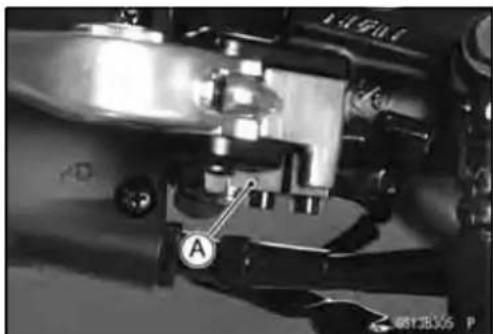
natural_image
Close-up mechanical assembly with labeled component A (no readable text or symbols)2-34PERIODICMAINTENANCE
PeriodicMaintenanceProcedures
Suspensions
FrontForks/RearShockAbsorberOperation Inspection
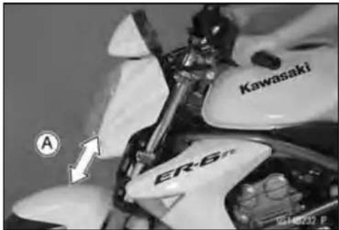
- Pumptheforksdownandup[A]4or5times,andinspect thesmoothstroke.
★Iftheforksdonotsmoothlyornoiseisfound,inspectthe forkoillevelorforkclamps(seeFrontForkOilChangein theSuspensionchapter).
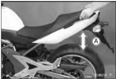
- Pumptheseatdownandup[A]4or5times,andinspect thesmoothstroke.
★Iftheshockabsorberdoesnotsmoothlystrokeornoise isfound, inspecttheoilleak(seeRearShockAbsorber OilLeakInspection).
FrontForkOilLeakInspection
- Visuallyinspectthefrontforks[A]foroilleakage.
★Replaceorrepairanydefectiveparts,ifnecessary.
RearShockAbsorberOilLeakInspection
- Visuallyinspecttheshockabsorber[A]foroilleakage.
★Iftheoilleakageisfoundonit,replacetheshockabsorber withanewone.
natural_image
Close-up of a motorcycle's side panel with a hand adjusting the seat area, showing no visible text or symbols.

natural_image
Close-up mechanical assembly showing a spring and bearing component (no visible text or symbols)PeriodicMaintenanceProcedures
SteeringSystem
SteeringPlayInspection
- Raisethefrontwheeloffthegroundwithjack.
SpecialTools-Jack:57001-1238
JackAttachment:57001-1608
- With the front wheelpointing straight ahead, alternately tapeach end of the handle bar. The front wheel should swing fully left and right from the force of gravity until the fork hit the stop.
★ If the wheel binds or catches before the stop, the steering istootight.
- Feelforsteeringloosenessbypushingandpullingthe forks.
★ Ifyoufeellooseness, thesteeringistooloose.
NOTE
○ Thecablesandwiringwillhavesomeeffectonthemotionoftheforkwhichmustbetakenintoaccount.
○Besurethewiresandcablesareproperlyrouted.
○ Thebearingsmustbeingoodconditionandproperly lubricatedinorderforanytesttobevalid.
SteeringPlayAdjustment
- Remove:
HeadlightAssy(seeHeadlightRemoval/Installationin theElectricalSystemchapter)
Handlebar(seeHandlebarRemovalintheSteering chapter)
UpperForkClampBolts[A]
SteeringStemHeadBoltPlug[B]
StemHeadBolt[C]
- Removethesteeringstemhead[D].
- Straightentheclaws[A]oftheclawwasher.
- Removethesteeringstemlocknut[B]andclawwasher [C].

natural_image
Close-up of a car wheel assembly with a hand adjusting the brake caliper (no visible text or symbols)

2-36PERIODICMAINTENANCE
PeriodicMaintenanceProcedures
- Adjustthesteering.
SpecialTool-SteeringStemNutWrench[A]:57001-1100
★Ifthesteeringistootight,loosenthestemnut[B]afraction ofaturn.
★Ifthesteeringistooloose,tightenthestemnutafraction ofaturn.
NOTE
○ Turnthestemnut1/8turnattimemaximum.
- Installtheclawwasher[A]sothatitsbentside[B]faces upward, and engage the bent claw with the grooves of stemlocknut[C].
- Handtightenthestemlocknutuntilittouchestheclaw washer.
- Tightenthestemlocknutclockwiseuntiltheclawsare alignedwiththegrooves(rangingfrom2ndto4th)ofstem nut[D],andbendthe2clawsdownward[E].
• Installthesteeringstemhead.
• Installthewasher, and tightenthestemheadbolt. - Tighten:
Torque-SteeringStemHeadBolt:108N·m(11.0kgf·m,80ft·lb)
FrontForkClampBolts(Upper):20N·m(2.0 kgf·m,15ft·lb)
- Checkthesteeringagain.
★Ifthesteeringisstilltootightortooloose,repeathead-justment. - Installtheremovedparts(seeappropriatechapters).
SteeringStemBearingLubrication
- Removethesteeringstem(seeStem,StemBearingRemovalintheSteeringchapter).
- Using a high flash-point solvent, wash the upper and lowerballbearingsinthecages,andwipetheupperand lowerouterraces,whicharepress-fittedintotheframe headpipe,cleanoffgreaseanddirt.
- Visuallychecktheouterracesandtheballbearings.
★Replace the bearing assemblies if they show wear or damage. - Packtheupperandlowerballbearings[A]inthecages withgrease,andapplylightcoatofgreasetotheupper andlowerouterraces.
- Installthesteeringstem(seeStem,StemBearingInstallationintheSteeringchapter).
- Adjustthesteering(seeSteeringPlayAdjustment).


natural_image
Technical line drawing of a mechanical assembly with labeled component A (no text or symbols beyond label)PeriodicMaintenanceProcedures
ElectricalSystem
SparkPlugConditionInspection
- Removethesparkplugs(seeSparkPlugReplacement).
- Visuallyinspectthesparkplugs.
★Ifthesparkplugcenterelectrode[A]and/orsideelectrode[B]arecorrodedordamaged,oriftheinsulator[C]iscracked,replacetheplug.
★ Ifthesparkplugisdirtiedorthecarbonisaccumulated, replacethesparkplug. - Measurethegap[D]withawire-typethicknessgauge.
★ Ifthegapisincorrect, replacethesparkplug.
Spark Plug Gap: 0.8 \~ 0.9 mm (0.03 \~ 0.04 in.)
- Usethestandardsparkplugoritsequivalent.
SparkPlug:CR9EIA-9

2-38PERIODICMAINTENANCE
PeriodicMaintenanceProcedures
LightsandSwitchesOperationInspection
FirstStep
- Turnontheignitionswitch.
- The following light should go on according to below table.
| CityLight[A] | goeson |
| Taillight[B] | goeson |
| LicensePlateLight[C] | goeson |
| MeterPanelLCD[D] | goeson |
| NeutralIndicatorLight(LED)[E] | goeson |
| OilPressure/WaterTemperatureWarning IndicatorLight(LED)[F] | goeson |
| FllndicatorLight(LED)[G] | goeson (about2seconds) |
★Ifthelightdoesnotgoon,inspectorreplacethefollowing item.
Battery(seeChargingConditionInspectionintheElectricalSystemchapter)
ApplicableBulb(seeWiringDiagramintheElectrical Systemchapter)
MeterUnitforMeterPanelLCD(seeElectronicCombinationMeterUnitInspectionintheElectricalSystem chapter)
MeterUnitforNeutralIndicatorLight(LED)(seeElectronicCombinationMeterUnitInspectionintheElectricalSystemchapter)
MeterUnitforOilPressure/WaterTemperatureWarning
IndicatorLight(LED)(seeElectronicCombinationMeter
UnitInspectionintheElectricalSystemchapter)
MeterUnitforFllndicatorLight(LED)(seeElectronic CombinationMeterUnitInspectionintheElectricalSystemchapter)
ECU(seeECUPowerSupplyInspectionintheFuelSystem(DFI)chapter)
MainFuse30AandTaillightFuse10A(seeFuseInspectionintheElectricalSystemchapter)
IgnitionSwitch(seeSwitchInspectionintheElectrical Systemchapter)
NeutralSwitch(seeSwitchInspectionintheElectrical Systemchapter)
Harness(see Wiring Inspection in the Electrical System chapter)
- Turnofftheignitionswitch.
• Thealllightsshouldgooff.
★Ifthelightdoesnotgooff,replaceignitionswitch.
SecondStep
- TurntheignitionswitchtoP(Park)position.
- Thecitylight,taillightandlicenseplatelightshouldgoon.
★Ifthelightdoesnotgoon,inspectorreplacethefollowing item.
IgnitionSwitch(seeSwitchInspectionintheElectrical Systemchapter)

natural_image
Close-up of a motorcycle's head and neck showing internal gear structure (no text or symbols visible)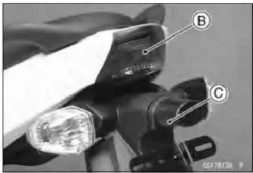

PeriodicMaintenanceProcedures
ThirdStep
- TurnontheturnsignalswitchA.
- TheleftorrightturnsignallightsBaccordingtotheswitchpositionsshouldflash.
- Theturnsignalindicatorlight(LED)[C]inthemeterunit shouldflash.
★ If the each light does not flash, inspector replace the following item.
TurnSignalLightBulb(seeTurnSignalLightBulbReplacementintheElectricalSystemchapter)
MeterUnitforTurnSignalLightIndicatorLight(LED) (seeElectronicCombinationMeterUnitInspectioninthe ElectricalSystemchapter)
TurnSignalRelayFuse10A(seeFuseInspectioninthe ElectricalSystemchapter)
TurnSignalSwitch(seeSwitchInspectionintheElectricalSystemchapter)
TurnSignalRelay(seeTurnSignalRelayInspectionin theElectricalSystemchapter)
Harness(see Wiring Inspection in the Electrical System chapter)
- Pushtheturnsignalswitch.
- Theturnsignallightsandindicatorlight(LED)shouldgo off.
★ Ifthelightdoesnotgooff, inspectorreplacethefollowing item.
TurnSignalSwitch(seeSwitchInspectionintheElectricalSystemchapter)
TurnSignalRelay(see TurnSignalRelayInspection in the Electrical Systemchapter)

natural_image
Close-up of a camera lens and adjustment knobs mechanism (no visible text or symbols)
natural_image
Close-up of a mechanical device with labeled component B, no visible text or symbols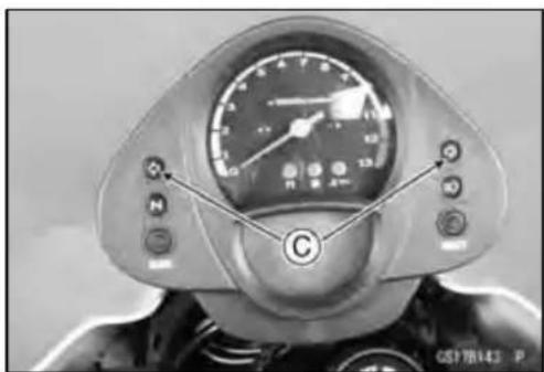
natural_image
Close-up of a scooter's front wheel with speedometer and control buttons (no visible text or symbols)FourthStep
- Setthedimmerswitch[A]tolowbeamposition.
- Starttheengine.
- Thelowbeamheadlightshouldgoon.
★ Ifthelowbeamheadlightdoesnotgoon, inspectorre-placethefollowingitem.
HeadlightLowBeamBulb(seeHeadlightBulbReplacementintheElectricalSystemchapter)
HeadlightFuse10A(seeFuseInspectionintheElectricalSystemchapter)
DimmerSwitch(seeSwitchInspectionintheElectrical Systemchapter)
HeadlightRelayinRelayBox(seeRelayCircuitInspectionintheElectricalSystemchapter)
Harness(see Wiring Inspection in the Electrical System chapter)

natural_image
Close-up of a mechanical device's control panel with labeled component A (no readable text or symbols beyond label)2-40PERIODICMAINTENANCE
PeriodicMaintenanceProcedures
- Setthedimmerswitchtohighbeamposition.
- Thelowbeam[A]andhighbeam[B]headlightsshould goon.
- Thehighbeamindicatorlight(LED)[C]shouldgoon.
★Ifthehighbeamheadlightand/orhighbeamindicatorlight(LED)doesnotgoon,inspectorreplacethefollowing item.
HeadlightHighBeamBulb(seeHeadlightBulbReplacementintheElectricalSystemchapter)
DimmerSwitch(seeSwitchInspectionintheElectrical Systemchapter) - Turnofftheenginestopswitch.
- Thelowbeamandhighbeamheadlightsshouldstaygoingon.
★Iftheheadlightsandhighbeamindicatorlight(LED)does gooff,inspectorreplacethefollowingitem.
HeadlightRelayinRelayBox(seeRelayCircuitInspectionintheElectricalSystemchapter) - Turnofftheignitionswitch.
- Theheadlightsandhighbeamindicatorlight(LED)should gooff.
HeadlightAimingInspection
- Inspecttheheadlightbeamforaiming.
★Iftheheadlightbeampointstoonesideratherthan straightahead,adjustthehorizontalbeam.
HeadlightBeamHorizontalAdjustment
- Turnthehorizontaladjuster[A]ontheheadlightwiththe screwdriverinoroutuntilthebeampointsstraightahead.
★Iftheheadlightbeampointstooloworhigh,adjustthe verticalbeam.
HeadlightBeamVerticalAdjustment
- Turntheverticaladjuster[A]ontheheadlightwiththe screwdriverinorouttoadjusttheheadlightvertically.
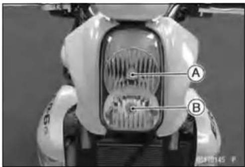

natural_image
Front view of a scooter's head and dashboard with visible controls and a speedometer (no text or symbols)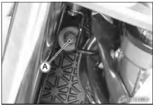
natural_image
Close-up of a mechanical component with a labeled part 'A' and a circular arrow, showing internal structure without any readable text or symbols.
natural_image
Close-up of mechanical components with visible wiring and a labeled component 'A' (no readable text or symbols beyond the label)PeriodicMaintenanceProcedures
NOTE
○ONhighbeam, the brightestpointsshouldbeslightly below horizontal with themotorcycleonitswheels and theriderseated. Adjust the headlight to the proper angle according to local regulations.
LowBeam[A]
HeightofHeadlightCenter[B]
HighBeam[C]

natural_image
Line drawing of a motorcycle with gear and wheel, showing motion direction (no text or symbols)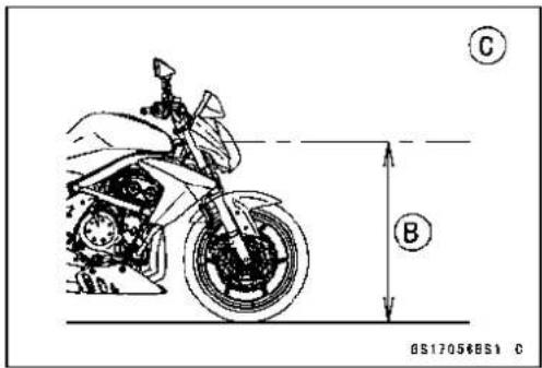
SidestandSwitchOperationInspection
- Inspectthesidestandswitch[A]operationaccordanceto belowtable.
SidestandSwitchOperation
| Sidestand | Gear Position | Clutch Lever | Engine Start | Engine Run |
| UpNeutralReleased | Starts | Continue running | ||
| UpNeutralPulledin | Starts | Continue running | ||
| Up | InGear | Released | Doesn't start | Stops |
| UpInGearPulledinStarts | Continue running | |||
| DownNeutralReleasedStarts | Continue running | |||
| DownNeutralPulledinStarts | Continue running | |||
| Down | InGear | Released | Doesn't start | Stops |
| Down | InGear | Pulledin | Doesn't start | Stops |

natural_image
Close-up of mechanical components with no visible text or symbols2-42PERIODICMAINTENANCE
PeriodicMaintenanceProcedures
★Ifthesidestandswitchoperationdoesnotwork,inspect orreplacethefollowingitem.
Battery(seeChargingConditionInspectionintheElectricalSystemchapter)
MainFuse30A(seeFuseInspectionintheElectrical Systemchapter)
IgnitionFuse10A(seeFuseInspectionintheElectrical Systemchapter)
IgnitionSwitch(seeSwitchInspectionintheElectrical Systemchapter)
SidestandSwitch(seeSwitchInspectionintheElectrical Systemchapter)
EngineStopSwitch(seeSwitchInspectionintheElectricalSystemchapter)
StarterButton(seeSwitchInspectionintheElectrical Systemchapter)
NeutralSwitch(seeSwitchInspectionintheElectrical Systemchapter)
StarterControlRelay(seeStarterRelayInspectionin the ElectricalSystemchapter)
RelayBox(seeRelayCircuitInspectionintheElectrical Systemchapter)
StarterCircuitRelay(seeRelayCircuitInspectioninthe ElectricalSystemchapter)
Harness(see Wiring Inspection in the Electrical System chapter)
★Iftheallpartsaregoodcondition,replaceECU(see ECURemoval/InstallationintheFuelSystem(DFI)chapter).
EngineStopSwitchOperationInspection
FirstStep
- Turnontheignitionswitch.
- Settheneutralposition.
- Turntheenginestopswitchtostopposition[A].
- Pushthestarterbutton.
• Theenginedoesnotstart.
★Iftheenginestarts,inspectorreplacethefollowingitem. EngineStopSwitch(seeSwitchInspectionintheElectricalSystemchapter)
SecondStep
- Turnontheignitionswitch.
- Settheneutralposition.
- Turntheenginestopswitchtorunposition[A].
- Pushthestarterbuttonandruntheengine.
- Turntheenginestopswitchtostopposition.
- Immediatelytheengine shouldbestop.
★Iftheengine does not stop, inspector replace the following item.
EngineStopSwitch(seeSwitchInspectionintheElectricalSystemchapter)
★Iftheenginestopswitchisgoodcondition,replace the ECU(seeECURemoval/InstallationintheFuelSystem (DFI)chapter).

natural_image
Close-up of a mechanical device with labeled component A (no readable text or symbols beyond label)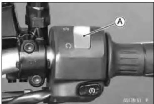
PeriodicMaintenanceProcedures
Others
ChassisPartsLubrication
- Beforelubricatingeachpart,cleanoffanyrustyspotswith rustremoverandwipeoffanygrease,oil,dirt,orgrime.
- Lubricatethepointslistedbelowwithindicatedlubricant.
NOTE
○ Wheneverthevehiclehasbeenoperatedunder wetorrainyconditions,orespeciallyafterusing a high-pressurewaterspray,performthegenerallubrication.
Pivots:LubricatewithGrease.
BrakeLever BrakePedal ClutchLever RearBrakeJointPin Sidestand
Points:LubricatewithGrease.
ClutchInnerCableUpperandLowerEnds[A] ThrottleInnerCableUpperandLowerEnds

Cables:LubricatewithRustInhibitor.
ClutchCable ThrottleCables
- Lubricatethecablesbyseepingtheoilbetweenthecable andhousing.
○Thecablemaybelubricatedbyusingacommercially availablepressurecablelubricatorwithanaerosolcable lubricant.

natural_image
Line drawing of two hands holding a syringe and a bottle, no text or symbols present- With the cable disconnected at both ends, the inner cable should move freely [A] within the cable housing.
★Ifcablemovementisnotfreeafterlubricating,ifthecable isfrayed[B],orifthecablehousingiskinked[C],replace thecable.

Bolts, Nuts and Fasteners Tightness Inspection
- Checkthetightnessoftheboltsandnutslistedhere. Also, checktoseethateachcotterpinisinplaceandingood condition.
NOTE
○ Fortheenginefasteners, check the tightness of them when the engine is cold (at room temperature).
★Ifthereareloosefasteners,retightenthemtothespecifiedtorquefollowingthespecifiedtighteningsequence. Refertotheappropriatechapterfortorquespecifications. Iftorquespecificationsarenotintheappropriatechapter, seetheStandardTorqueTable.Foreachfastener,first loosenitby1/2turn,thentightenit.
★Ifcotterpinsaredamaged, replacethemwithnewones.
Bolt, Nutand Fastenertobechecked
Engine:
ClutchLeverPivotNut
EngineMountingBoltsandNuts
ExhaustPipeManifoldHolderNuts
MufflerBodyMountingBolts
Wheels:
FrontAxle
FrontAxleClampBolt
RearAxleNut
RearAxleNutCotterPin
Brakes:
BrakeLeverPivotNut
BrakePedalBolt
BrakeRodJointCotterPin
CaliperMountingBolts
FrontMasterCylinderClampBolts
RearMasterCylinderMountingBolts
Suspension:
FrontForkClampBolts
RearShockAbsorberBoltandNut
SwingarmPivotShaftNut
Steering:
SteeringStemHeadBolt
HandlebarHolderBolts
Others:
FootpegStayBolts
FrontFenderBolts
SidestandBolt
PeriodicMaintenanceProcedures
ReplacementParts
AirCleanerElementReplacement
- RefertotheAirCleanerElementCleaning.
EngineOilChange
- Situatethemotorcyclesothatis vertical after warming up the engine.
- Unscrewtheoilfillerplug[A].
-
Placeonoilpanbeneaththeengine.
-
Removetheengineoidrainbolt[A]todraintheoil.
○Theoilintheoilfiltercanbedrainedbyremovingthefilter (seeOilFilterReplacement).
★Replacethedrainboltgasket[B]withanewone. - Tightenthedrainbolt.
Torque-EngineOilDrainBolt:20N·m(2.0kgf·m,15ft·lb)
- Pourinthespecifiedtypeandamountofoil.


RecommendedEngineOil
Type:
APISE,SForSG
APISH,SJorSLwithJASOMA
Viscosity:
SAE10W-40
Capacity:1.7L(1.8USqt)(whenfilterisnot removed)
1.9L(2.0USqt)(whenfilterisremoved)
2.4L(2.5USqt)(whenengineis completelydry)
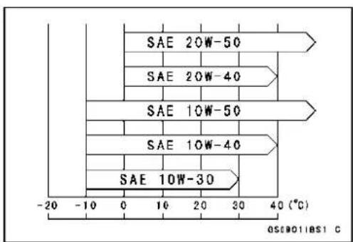
bar
| Category | Value (°C) | |---|---| | SAE 20W-50 | -10 | | SAE 20W-40 | 30 | | SAE 10W-50 | 30 | | SAE 10W-40 | 30 | | SAE 10W-30 | 30 | The chart displays a single bar representing the temperature for each category. The x-axis ranges from -20 to 40 (°C), and the labels above the bars indicate the duration in seconds. The label 'OSB01IBS1 C' appears at the bottom right of the chart.NOTE
Although 10W-40engineoilistherecommendedoil formostconditions, the oil viscosity may need to be changed to accommodate atmospheric conditions in your riding area.
- Checktheoillevel(seeOilLevelInspectionintheEngine LubricationSystemchapter).
2-46PERIODICMAINTENANCE
PeriodicMaintenanceProcedures
OilFilterReplacement
- Draintheengineoil(seeEngineOilChange).
-
Removetheoilfilter[A]withtheoilfilterwrench[B].
SpecialTool-OilFilterWrench:57001-1249 -
Replacethefilterwithanewone.
- Applyengineoiltothegasket[A]beforeinstallation.
- Tightenthefilterwiththeoilfilterwrench.
Torque-OilFilter:17.2N·m(1.75kgf·m,13ft·lb)
NOTE
○ Handtighteningoftheoilfiltercannotbeallowedsince itdoesnotreachtothistighteningtorque.
- Pourinthespecifiedtypeandamountofoil(seeEngine OilChange).
FuelHoseReplacement
CAUTION
Whenremovingandinstallingthefuelhosejoint,do notapplystrongforcetotheoutletpipeonthefuel pumpanddeliverypipeonthethrottlebodyassy. Thepipesmadefromresincouldbedamaged.
- Removethefueltank(seeFuelTankRemovalintheFuel System(DFI)chapter).
- Besuretoplaceapieceofcloth[A]aroundthefuelhose joint.
- Insertaminusscrewdriver[B]intotheslit[C]onthejoint lock.
- Turn[A]thedrivertodisconnectthejointlock[B].
- Pull[C]thefuelhosejoint[D]outofthedeliverypipe.
WARNING
Bepreparedforfuelspillage;anyspilledfuelmust becompletelywipedupimmediately. Whenthefuelhoseisdisconnected,fuelspillsout fromthehoseandthepipe.Coverthehoseconnectionwithacleanshoptoweltopreventfuelspillage.


natural_image
Technical line drawing of a mechanical component with labeled point A (no text or symbols beyond label)

PeriodicMaintenanceProcedures
• Installthenewfuelhose.
- Insert[A]thefuelhosejoint[B]straightontothedelivery pipeuntilthehosejointclicks.
- Push[C]thejointlock[D].
- Pushandpull[A]thefuelhosejoint[B]backandforth morethantwotimesandmakesureitislockedand doesn'tcomeoff.
WARNING
Makesurethefuelhosejointisinstalledcorrectly onthedeliverypipeorthefuelcouldleak.
★ Ifitcomesoff, reinstallthehosejoint.
- Runthefuelhosecorrectly(seeCable, Wire, and Hose RoutingsectionintheAppendixchapter).
• Installtheremovedparts(seeappropriatechapters).
- Starttheengineandcheckthefuelhoseforleaks.
CoolantChange
WARNING
Toavoidburns, donotremovetheradiatorcapor trytochangethecoolantwhentheengineisstill hot. Wait until cools down. Coolantontires will makethemslippery and can cause an accident and injury. Immediately wipe up or wash away any coolant that spills on the frame, engine, or other painted parts. Since coolantisharmful to the human body, donot use for drinking.
- Remove:
RightCenterFairing(seeCenterFairingRemovalinthe Framechapter)
LowerFairing(seeLowerFairingRemovalintheFrame chapter) - Remove:
ReserveTankBolts[A] ReserveTank[B]
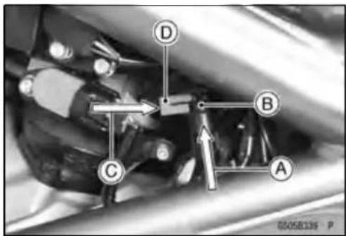

natural_image
Close-up of a mechanical assembly with labeled parts A and B, showing no readable text or symbols beyond labels
2-48PERIODICMAINTENANCE
PeriodicMaintenanceProcedures
- Put[A]theprojection[B]onthereservetankintothehole [C]ontheframebracket,andplacethereservetankon therightsideofframe.
- Placeacontainerunderthewaterpumpdrainbolt[A], thenremovethedrainbolt.
- Removetheradiatorcap[A]intwosteps.Firstturnthe capcounterclockwisetothefirststop.Thenpushandturn itfurtherinthesamedirectionandremovethecap. ○Thecoolantwilldrainfromtheradiatorandengine.
- Turnover[A]thereservetank,removethecap,andpour thecoolantintoasuitablecontainer. - Placethereservetankontherightsideofframe. - Tightenthedrainboltwiththegasket. - Replacethedrainboltgasketwithanewone. Torque-WaterPumpDrainBolt:7.0N·m(0.70kgf·m,92 in·lb)

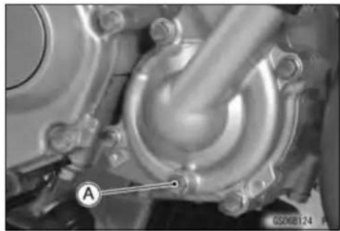
natural_image
Close-up of a mechanical component with labeled section A, showing internal structure and mounting brackets (no readable text or symbols beyond label)
natural_image
Close-up mechanical component with labeled section A, showing no readable text or symbols beyond the label
PeriodicMaintenanceProcedures
- Whenfillingthecoolant,chooseasuitablemixtureratio byreferringtothecoolantmanufacturer'sdirections.
CAUTION
Softordistilledwatermustbeusedwiththeantifreezeinthecoolingsystem. Ifhardwaterisusedinthesystem, itcausesscales accumulationinthewaterpassages, and considerablyreducetheefficiencyofthecoolingsystem.
WaterandCoolantMixtureRatio(Recommended)
SoftWater:50%
Coolant:50%
FreezingPoint: -35^(-31^)
TotalAmount: 1.2L(1.3USqt)
- Filltheradiatoruptothefillerneck[A]withcoolant.
NOTE
○Pourinthecoolantslowlysothatitcanexpeltheair fromtheengineandradiator.
- Checkthecoolingsystemforleaks.
- Taptheradiatorhosestoforceanyairbubblescaught inside.
- Filltheradiatoruptothefillerneckwithcoolant.
- Temporarily installthereservetanktotheframewithtwo mountingbolts.
- Fillthereservetankuptothe“F”(full)levelline[A]with coolantandinstallthecap[B].
- Starttheengine, warmitupthoroughly untiltheradiator fanturnson and thenstoptheengine.
- Checkthecoolantlevelinthereservetankaftertheenginecoolsdown.
★ If the coolant level is slower than the "L" levelline, add coolant to the "F" levelline.
CAUTION
Donotaddmorecoolantabovethe“F”levelline.
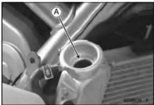
natural_image
Close-up of a mechanical component with labeled point A pointing to a cylindrical opening (no readable text or symbols)
2-50PERIODICMAINTENANCE
PeriodicMaintenanceProcedures
RadiatorHoseandO-ringReplacement
- Drainthecoolant(seeCoolantChangeinthePeriodic Maintenancechapter).
- Remove: ThermostatHousingA WaterPumpCoverB Hoses[C] O-rings[D]
- ApplygreasetothenewO-ringsandinstallthem.
- Instalthenewhosesandtightentheclampssecurely.
- Fillthecoolant(seeCoolantChangeinthePeriodicMaintenancechapter).
- Checkthecoolingsystemforleaks.
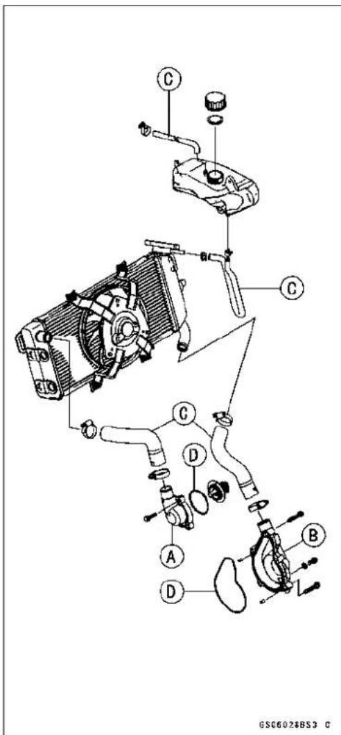
PeriodicMaintenanceProcedures
BrakeHoseandPipeReplacement
CAUTION
Brakefluidquicklyruinspaintedplasticsurfaces; anyspilledfluidshouldbecompletelywashedaway immediately.
- Removethebanjobolts[A].
- Whenremovingthebrakehose, takecarenottospillthe brakefluidonthepaintedorplasticparts.
- When removing the brake hoses [B], temporarily secure the end of the brake hosetosome high placeto keep fluid lossto a minimum.
- Immediatelywashawayanybrakefluidthatspills.
- Therearewashersoneachsideofthebrakehosefitting. Replacethemwithnewoneswheninstalling.
- Tighten:
Torque - Brake Hose Banjo Bolts: 25 N·m (2.5 kgf·m, 18 ft·lb)


- Wheninstallingthehoses,avoidsharpbending,kinking,flattingortwisting,androutethehosesaccordingto Cable,Wire,andHoseRoutingsectionintheAppendix chapter.
- Fillthebrakelineafterinstallingthebrakehose(see BrakeFluidChange).
BrakeFluidChange
NOTE
○ Theproceduretochangethefrontbrakefluidisasfollows. Changingtherearbrakefluidisthesameasfor thefrontbrake.
2-52PERIODICMAINTENANCE
PeriodicMaintenanceProcedures
- Levelthebrakefluidreservoir.
- Removethereservoircapanddiaphragm.
- Removetherubbercapfromthebleedvalve[A]onthe caliper.
- Attachaclearplastichose[B]tothebleedvalve,andrun theotherendofthehoseintoacontainer.
- Fillthereservoirwithfreshspecifiedbrakefluid.
- Changethebrakefluid. ○Repeatthisoperationuntilfreshbrakefluidcomesout fromtheplasticchoseorthecolorofthefluidchanges.
- Openthebleedvalve[A].
- Applythebrakeandholdit[B].
3.Closethebleedvalve[C]. - Releasethebrake[D].
NOTE
○ Thefluidlevelmustbecheckedoftenduringthechangingoperationandreplenishedwithfreshbrakefluid. If thefluidinthereservoirrunsoutanytimeduringthe changingoperation,thebrakeswillneedtobebled sinceairwillhaveenteredthebrakeline.
○ FrontBrake: Repeat the abovesteps for the other caliper.
- Removetheclearplastichose.
• Installthediaphragmandreservoircap. - Tighten:
Torque-FrontBrakeReservoirCapScrews:1.0N·m(0.10 kgf·m,9in·lb)
-
Follow the procedure below to install therear brake fluid reservoir cap correctly.
○First,tightentherearbrakefluidreservoircap[B]clockwise[C]byhanduntilslightresistanceisfeltindicating thatthecapisseatedonthereservoirbody,thentighten thecapanadditional1/6turn[D]whileholdingthebrake fluidreservoirbody[A]. -
Tightenthebleedvalve, and installtherubbercap.
- Afterchangingthefluid, checkthebrakeforgoodbraking power, nobrakedrag, andnofluidleakage.
★Ifnecessary,bleedtheairfromthelines.
Torque-BleedValve:7.8N·m(0.80kgf·m,69in·lb)

natural_image
Close-up of a mechanical assembly with labeled parts A and B (no readable text or symbols beyond labels)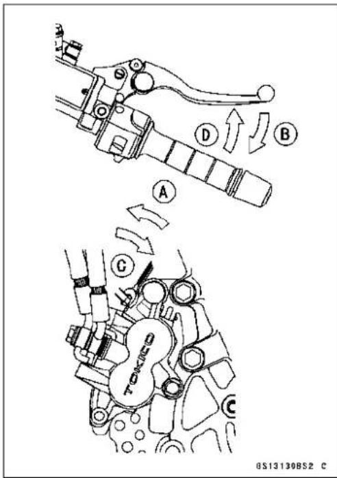

PeriodicMaintenanceProcedures
MasterCylinderRubberPartsReplacement
FrontMasterCylinderDisassembly
- Removethefrontmastercylinder(seeFrontMasterCylinderRemovalintheBrakeschapter).
- Removethereservoircapanddiaphragm, and pour the brakefluid into a container.
- Unscrewthelocknutandpivotbolt, andremovethebrake lever.
- Pullthedustcover[A]outofplace,andremovethecirclip [B].
SpecialTool-InsideCirclipPliers:57001-143
- Pulloutthepiston[C], secondarycup[D], primarycup[E], andreturnspring[F].
CAUTION
Donotremovethesecondarycupfromthepiston sinceremovalwilldamageit.
RearMasterCylinderDisassembly
NOTE
○ Donotremovethepushrodclevisformastercylinder disassemblysinceremovalreguiresbrakepositionadjustment.
- Removetherearmastercylinder(seeRearMasterCylinderRemovalintheBrakeschapter).
- Slidethedustcoveronthepushrodoutofplace,and removethecirclip.
SpecialTool-InsideCirclipPliers:57001-143
- Pulloutthepushrodwiththepistonstop.
- Takeoffthepiston[A], secondarycup[B], primarycup[C] and returnspring[D].
CAUTION
Donotremovethesecondarycupfromthepiston sinceremovalwilldamageit.
MasterCylinderAssembly
- Beforeassembly, cleanallpartsincludingthemaster cylinderwithbrakefluidoralcohol.
CAUTION
Exceptforthediscpadsanddisc,useonlydisc brakefluid,isopropylalcohol,orethylalcoholfor cleaningbrakeparts.Donotuseanyotherfluidfor cleaningtheseparts.Gasoline,engineoil,orany otherpetroleumdistillatewillcausedeteriorationof therubberparts.Oilspilledonanypartwillbedifficulttowashoffcompletely,andwilleventuallydeterioratetherubberusedinthediscbrake.
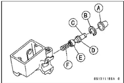
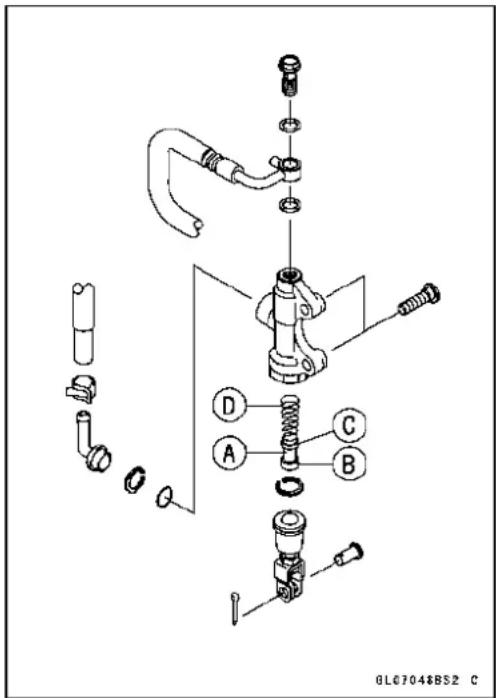
2-54PERIODICMAINTENANCE
PeriodicMaintenanceProcedures
- Applybrakefluidtothenewpartsandtotheinnerwallof thecylinder.
- Takecarenottoscratchthepistonortheinnerwallofthe cylinder.
- Tightenthebrakeleverpivotboltandlocknut.
- Applysiliconegrease. BrakeLeverPivotBolt
- Tighten:
Torque-BrakeLeverPivotBolt:1.0N·m(0.10kgf·m,9 in·lb) BrakeLeverPivotBoltLocknut:5.9N·m(0.60 kgf·m,52in·lb)
CaliperRubberPartsReplacement FrontCaliperDisassembly
- Remove:
FrontCaliper(seeFrontCaliperRemovalintheBrakes chapter) BrakePads(seeFrontBrakePadRemovalintheBrakes chapter)
• Usingcompressedair, removethepistons.
○Coverthepistonareawithaclean,thickcloth[A].
○Blowcompressedair[B]intotheholeforthebanjoboltto removethepiston.
WARNING
Toavoidseriousinjury,neverplaceyourfingersor palminfrontofthepiston.Ifyouapplycompressed airintothecaliper,thepistonmaycrushyourhand orfingers.
○Pulloutthepistonsbyhand.
- Removethedustseals[A]andfluidseals[B].
- Removethebleedvalve[C]andrubbercap[D].

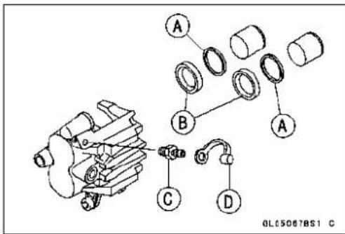
NOTE
○ Ifcompressedairisnotavailable, withthebrakehose stillattached, applythebrakelevertoremovethepiston. Theremainingprocessisasdescribedabove.
FrontCaliperAssembly
- Cleanthecaliperpartsexceptforthepads.
CAUTION
Forcleaningtheparts, useonlydiscbrakefluid, isopropylalcohol, orethylalcohol.
• Installthebleedvalveandrubbercap.
Torque-BleedValve:7.8N·m(0.80kgf·m,69in·lb)
PeriodicMaintenanceProcedures
- Replacethefluidseals[A]withnewones.
○Applybrakefluidtothefluidseals, and install them into the cylinders by hand. -
Replacethedustseals[B]withnewonesiftheyaredamaged.
○Applybrakefluidtothedustseals, and install them into the cylinders by hand. -
Applybrakefluidtotheoutsideofthepistons, and push themintoeachcylinderbyhand.
- Checktheshaftrubberfrictionboot[A]andthedustcover [B]replacethemwithnewonesiftheyaredamaged.
- ApplyathincoatofPBC(PolyButylCuprysil)greaseto thecaliperholdershafts[C]andholderholesD.
• Installtheanti-rattlespring[A].
- Installthepads(seeFrontBrakePadInstallationinthe Brakeschapter).
- Wipeupanyspilledbrakefluidonthecaliperwithwet cloth.


natural_image
Mechanical component diagram showing internal parts and a labeled section (A), no readable text or symbols present.RearCaliperDisassembly
- Removetherearcaliper(seeRearCaliperRemovalin theBrakeschapter).
- Removethepadsandanti-rattlespring(seeRearBrake PadRemovalintheBrakeschapter).
- Usingcompressedair,removethepiston.
○Coverthepistonareawithaclean,thickcloth[B].
○Blowcompressedair[A]intotheholeforthebanjoboltto removethepiston.

WARNING
To avoid serious injury, never place your fingers or palminidethecaliper opening. If you apply compressed air into the caliper, the piston may crush your handorfingers.
- Removethedustsealandfluidseal.
- Removethebleedvalveandrubbercap.
NOTE
○ Ifcompressedairisnotavailable, withthebrakehose stillattached, applythebrakepedaltoremovethepiston. Theremainingprocessisasdescribedabove.
2-56PERIODICMAINTENANCE
PeriodicMaintenanceProcedures
RearCaliperAssembly
- Cleanthecaliperpartsexceptforthepads.
CAUTION
Forcleaningoftheparts,useonlydiscbrakefluid, isopropylalcohol,orethylalcohol.
• Installthebleedvalveandrubbercap.
Torque-BleedValve:7.8N·m(0.80kgf·m,69in·lb)
- Replacethefluidseal[A]withanewone.
○Applybrakefluidtothefluidseal, and installitintothe cylinderbyhand.
- Replacethedustseal[B]withanewoneifitisdamaged.
○Applybrakefluidtothedustseal, and installitintothe cylinderbyhand.
- Applybrakefluidtotheoutsideofthepiston,andpushit intothecylinderbyhand.
- Replacetheshaftrubberfrictionboot[A]anddustcover [B]iftheyaredamaged.
- ApplyathincoatofPBC(PolyButylCuprysil)greaseto thecaliperholdershafts[C]andholderholesD.
• Installtheanti-rattlespring[A]inthecaliperasshown.
- Installthepads(seeRearBrakePadInstallationinthe Brakeschapter).
- Wipeupanyspilledbrakefluidonthecaliperwithwet cloth.
SparkPlugReplacement
- Remove:
StickCoils(seeStickCoil(IgnitionCoiltogetherwith SparkPlugCap)RemovalintheElectricalSystemchapter)
- Removethesparkplugsusingthe16mmplugwrench [A].
Owner's Tool-SparkPlugWrench, 16mm:92110-1132


natural_image
Mechanical component with labeled section A, showing internal parts and mounting features (no readable text or symbols)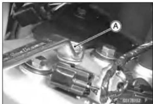
natural_image
Close-up of mechanical components with a labeled section A (no readable text or symbols)PeriodicMaintenanceProcedures
- Insertthesparkplugverticallyintotheplugholewiththe sparkpluginstalledintheplugwrench[A].
Owner's Tool-Spark Plug Wrench, 16mm:92110-1132
- Tighten:
Torque-SparkPlugs:15N·m(1.5kgf·m,11ft·lb)
- Install:
StickCoils(seeStickCoil(IgnitionCoiltogetherwith SparkPlugCap)InstallationintheElectricalSystem chapter)

natural_image
Close-up of an engine cylinder assembly with visible components and no text or symbolsFuelSystem(DFI)
TableofContents
Exploded View.... 3-4
DFI System.... 3-8
DFI System.... 3-10
DFI Parts Location.... 3-13
Specifications 3-14
Special Tools and Sealant 3-16
DFI Servicing Precautions 3-18
DFI Servicing Precautions 3-18
Troubleshooting the DFI System 3-20
Outline 3-20
Outline.... 3-20
Inquiries to Rider.... 3-24
Inquiries to Rider 3-24
DFI System Troubleshooting Guide 3-27
Self-Diagnosis 3-35
Self-diagnosis Outline 3-35
Self-diagnosis Outline 3-35
Self-diagnosis Procedures.... 3-35
Self-diagnosis Procedures 3-35
Service Code Clearing Procedures 3-36
ServiceCodeClearingProcedures....3-36
How to Read Service Codes.... 3-38
How to Read Service Codes.... 3-38
How to Erase Service Codes.... 3-38
How to Erase Service Codes 3-38
Service Code Table 3-39
Service Code Table 3-39
Backups 3-40
Backups 3-40
Main Throttle Sensor (Service Code 11) 3-42
MainThrottleSensorRemoval/Adjustment....3-42
Input Voltage Inspection.... 3-42
Output Voltage Inspection.... 3-43
Resistance Inspection.... 3-44
Inlet Air Pressure Sensor (Service Code 12).... 3-45
Removal.... 3-45
Installation.... 3-45
Input Voltage Inspection.... 3-45
Output Voltage Inspection 3-46
InletAirTemperatureSensor(ServiceCode13)....3-50
Removal/Installation.... 3-50
Output Voltage Inspection 3-50
Sensor Resistance Inspection 3-51
Water Temperature Sensor (Service Code 14) 3-52
WaterTemperatureSensorRemoval/Installation....3-52
Water Temperature Sensor Output Voltage Inspection.... 3-52
Sensor Resistance Inspection 3-53
Crankshaft Sensor (Service Code 21).... 3-54
CrankshaftSensorRemoval/Installation....3-54
Crankshaft Sensor Inspection 3-54
Speed Sensor (Service Code 24, 25) 3-55
SpeedSensorRemoval/Installation....3-55
Speed Sensor Inspection 3-55
SpeedSensorInputVoltageInspection....3-55
SpeedSensorOutputVoltageInspection....3-55
Vehicle-down Sensor (Service Code 31) 3-57
Vehicle-down Sensor Removal 3-57
Vehicle-down Sensor Installation 3-57
Vehicle-down Sensor Inspection.... 3-57
Subthrottle Sensor (Service Code 32).... 3-60
SubthrottleSensorRemoval/Adjustment....3-60
SubthrottleSensorInputVoltageInspection....3-60
SubthrottleSensorOutputVoltageInspection....3-61
SubthrottleSensorResistanceInspection....3-62
OxygenSensor-notactivated(ServiceCode33)-EuropeModel....3-63
OxygenSensorRemoval/Installation....3-63
Oxygen Sensor Inspection.... 3-63
Stick Coils (#1, #2: Service Code 51, 52) 3-65
Stick Coil Removal/Installation.... 3-65
Stick Coil Input Voltage Inspection.... 3-65
Radiator Fan Relay (Service Code 56).... 3-67
RadiatorFanRelayRemoval/Installation....3-67
Radiator Fan Relay Inspection.... 3-67
Subthrottle Valve Actuator (Service Code 62) 3-68
Subthrottle Valve Actuator Removal 3-68
SubthrottleValveActuatorAudibleInspection....3-68
SubthrottleValveActuatorVisualInspection....3-68
Subthrottle Valve Actuator Resistance Inspection....3-68
SubthrottleValveActuatorInputVoltageInspection....3-69
Air Switching Valve (Service Code 64) 3-70
AirSwitchingValveRemoval/Installation....3-70
Air Switching Valve Inspection 3-70
OxygenSensorHeater(ServiceCode67)-EuropeModel....3-71
OxygenSensorHeaterRemoval/Installation....3-71
OxygenSensorHeaterInspection....3-71
OxygenSensor-IncorrectOutputVoltage(ServiceCode94)-EuropeModel....3-73
OxygenSensorRemoval/Installation....3-73
Oxygen Sensor Inspection 3-73
FI Indicator Light (LED) 3-75
FI Indicator Light (LED) Inspection 3-76
ECU 3-77
ECU Removal 3-77
ECU Installation 3-77
ECU Power Supply Inspection 3-78
Fuel Line 3-80
Fuel Pressure Inspection 3-80
Fuel Flow Rate Inspection 3-82
Fuel Pump 3-84
Fuel Pump Removal 3-84
Fuel Pump Installation 3-84
Fuel Pump Operation Inspection 3-85
FuelPumpOperatingVoltageInspection....3-85
Pressure Regulator Removal.... 3-86
Pump Screen, Fuel Filter Cleaning 3-86
Fuel Injectors 3-88
Removal/Installation.... 3-88
Audible Inspection.... 3-88
FuelInjectorPowerSourceVoltageInspection....3-88
FuelInjectorOutputVoltageInspection....3-89
Injector Signal Test.... 3-89
Injector Resistance Inspection 3-90
Injector Unit Test 3-91
Injector Fuel Line Inspection 3-91
Throttle Grip and Cables 3-93
Throttle Grip Free Play Inspection 3-93
Throttle Grip Free Play Adjustment.... 3-93
Throttle Cable Installation 3-93
Throttle Cable Lubrication 3-93
Throttle Body Assy 3-94
Idle Speed Inspection 3-94
EngineVacuumSynchronizationInspection/Adjustment....3-94
HighAltitudePerformanceAdjustment....3-94
Throttle Body Assy Removal 3-94
Throttle Body Assy Installation.... 3-95
Throttle Body Assy Disassembly 3-96
Throttle Body Assy Assembly 3-97
Air Cleaner.... 3-98
AirCleanerElementRemoval/Installation....3-98
Air Cleaner Element Inspection 3-98
Air Cleaner Oil Draining 3-98
Air Cleaner Housing Removal 3-98
Air Cleaner Housing Installation 3-99
Fuel Tank 3-100
Fuel Tank Removal 3-100
Fuel Tank Installation 3-101
Fuel Tank and Cap Inspection 3-102
Fuel Tank Cleaning 3-103

ExplodedView
| No.Fastener | Torque | Remarks | ||
| N·mkgf· | mft·lb | |||
| 1 FuelPumpBolts9.81.087in·lb | L, S | |||
2.FIIndicatorLEDLight
-
Throttle Cable (Accelerator)
-
ThrottleCable(Decelerator)
-
ThrottleBodyAssy
-
Injectors
CL:Applycablelubricant.
EO:Applyengineoil.
G:Applygrease.
L: Applyanon-permanentlockingagent.
R:ReplacementParts
S: Follow the specified tightening sequence.

ExplodedView
| No.Fastener | Torque | Remarks | |||
| N·mkgf·mft·lb | |||||
| 1 | WaterTemperatureSensor | 121.2106in·lb | |||
| 2SpeedSensorBolt7.80.8066in·lbL | |||||
| 3 | Oxygen Sensor (Europe Model) | 44.1 | 4.50 | 32.5 | |
- InletAirPressureSensor
- AirSwitchingValve
- InletAirTemperatureSensor
- CrankshaftSensor
- SealedBattery
- RelayBox
- StickCoil
- Vehicle-downSensor
- ECU(ElectronicControlUnit)
L: Applyanon-permanentlockingagent.
R: ReplacementParts
SS: Applysiliconesealant.
DFISystem

6017022CH5

DFISystem
- IgnitionSwitch
2.StarterLockoutSwitch - StarterRelay
- Tachometer
5.FIIndicatorLight(LED)
6.InletAirPressureSensor
7.SparkPlug
8.CrankshaftSensor - Injector
10.MainThrottleSensor
11.DeliveryPipe
12.SubthrottleSensor
13.SubthrottleValve
14.MainThrottleValve
15.SubthrottleValveActuator
16.FuelPump - PressureRegulator
18.FuelTank
19.AirCleanerElement
20.AirSwitchingValve
21.InletAirTemperatureSensor
22.AirCleanerHousing
23.NeutralSwitch
24.SpeedSensor - Vehicle-downSensor
26.OxygenSensor(EuropeModel) - ECU(ElectronicControlUnit)
28.SealedBattery - AirFlow
30.FuelFlow
31.WaterTemperatureSensor
DFISystemWiringDiagram

DFISystem
PartName
- OxygenSensor(EuropeModel)
2.CrankshaftSensor - InletAirTemperatureSensor
- WaterTemperatureSensor
- Water-proofJointE
- Injectors
- Vehicle-downSensor
- Water-proof JointD
9.InletAirPressureSensor
10.MainThrottleSensor
11.SubthrottleSensor
12.SubthrottleValveActuator
13.SpeedSensor - AirSwitchingValve
15.Water-proofJointC
16.StickCoil
17.FanMotor - EngineStopSwitch
19.IgnitionSwitch
20.FIIndicatorLight(LED)
21.WaterTemperatureGauge
22.Tachometer
23.Speedometer
24.Water-proofJointA
25.Water-proofJointB
26.OxygenSensorHeaterFuse10A
27.RadiatorFanFuse15A
28.ECUFuse15A
29.IgnitionFuse10A
30.RadiatorFanRelay
31.ECUMainRelay
32.FuelPumpRelay
33.RelayBox
34.MainFuse30A
35.Battery
36.FrameGround
37.FuelPump
38.DiagnosisConnector
39.Self-diagnosisTerminal
40.JointConnector
41.ECU

GC17969BH2 C
TerminalNames
- Subthrottle Valve Actuator Drive Signal 2
2.SubthrottleValveActuatorDriveSignal1
-
Water Temperature Warning Light Signal
-
Unused
5.OxygenSensorSignal
6.SpeedSensorSignal
7.MainThrottleSensorSignal
- InletAirPressureSensorSignal
9.Unused
10.PowerSupplytoSensors
-
Vehicle-downSensorSignal
-
NeutralSwitchSignal
13.CrankshaftSensor(+)Signal
14.Unused
15.Unused
-
PowerSupplytoECU(fromECUMainRelay)
-
PowerSupplytoECU(fromBattery)
18.SubthrottleValveActuatorDriveSignal4
19.SubthrottleValveActuatorDriveSignal3
20.WaterTemperatureSensorSignal
21.Unused
22.Self-diagnosisTerminal
23.Unused
24.SubthrottleSensorSignal
25.Unused
26.InletAirTemperatureSensorSignal
27.Unused
28.GroundtoSensors
29.OxygenSensorHeaterSignal
30.CrankshaftSensor(−)Signal
31.Unused
32.ExternalDiagnosisSystemSignal
33.Unused
34.GroundtoECU
- EngineStopSwitchSignal
36.StarterLockoutSwitchSignal
37.StarterButtonSignal
38.Unused
39.FuelPumpRelaySignal
40.AirSwitchingValveSignal
41.FuellInjector#2Signal
42.FuellInjector#1Signal
43.StickCoil#1Signal
44.SidestandSwitchSignal
45.RadiatorFanRelaySignal
- ExternalCommunicationLine(Mode Switch)
47.TachometerSignal
48.FIIndicatorLEDLight
49.-
50.GroundforFuelSystem
51.GroundforignitionSystem
52.StickCoil#2Signal
DFIPartsLocation
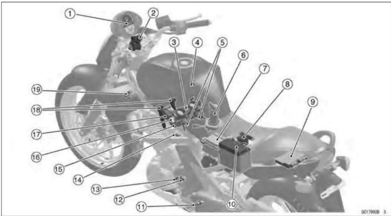
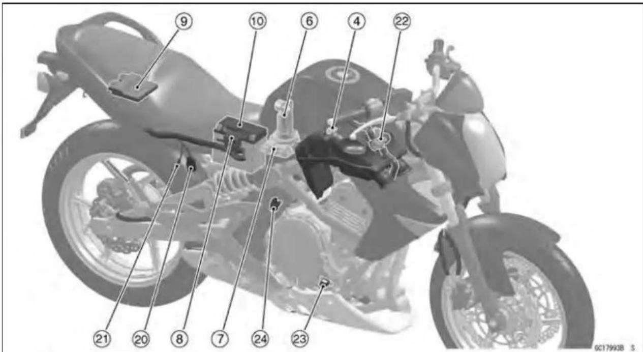
DFI:DigitalFuelInjectionParts
1.FIIndicatorLightLED(DFI)
2.IgnitionSwitch
3. ThrottleBodyAssy
4.InletAirTemperatureSensor
5. Injectors
6.FuelPump
7. RelayBox(ECUMainRelay, FuelPump Relay, RadiatorFanRelay)
8. FuseBox(ECUFuse15A, OxygenSensorHeaterFuse10A)
9.ECU
10.SealedBattery
11.OxygenSensor
12.SpeedSensor
13.NeutralSwitch
14.WaterTemperatureSensor
15.SubthrottleSensor
16.MainThrottleSensor
17.SubthrottleValveActuator
18.StickCoils
19.InletAirPressureSensor
20.DiagnosisConnector
21.Self-diagnosisTerminal
22.AirSwitchingValve
23.CrankshaftSensor
24. Vehicle-downSensor
Specifications
| ItemStandard | |
| DigitalFuelInjectionSystem | |
| IdleSpeed1300±50r/min(rpm) | |
| ThrottleAssy: | |
| TypeTwobarreltype | 38mm(1.50in.) |
| Bore | |
| ECU(ElectronicControlUnit): | |
| MakeDenso | |
| Type | Digitalmemorytype,withbuiltinICigniter,sealed withresin |
| UsableEngineSpeed100~12000r/min(rpm) | |
| FuelPressure(HighPressureLine): | |
| RightafterIgnitionSwitchON323kPa(3.3kgf/cm2,47psi)withfuelpumprunning | |
| After3SecondsfromIgnitionSwitchON265kPa(2.7kgf/cm2,38psi)withfuelpumpstopped | |
| WithEngineIdling333kPa(3.4kgf/cm2,48psi)withfuelpumprunning | |
| FuelPump: | |
| Typeln-tankfrictionpump | |
| Discharge60mLormorefor3seconds | |
| FuelInjectors: | |
| TypeINP-287 | |
| NozzleType | Onespraytypewith12holes |
| Resistance | about 11.7 ~ 12.3 Ω at 20°C (68°F) |
| MainThrottleSensor: | Non-adjustableandnon-removable |
| Input Voltage | 4.75 ~ 5.25 V DC between BL and BR/BK leads |
| Output Voltage at Idle Throttle Opening | 1.073 ~ 1.077 V DC between Y/W and BR/BK leads |
| Output Voltage at Full Throttle Opening | 4.29 ~ 4.49 V DC between Y/W and BR/BK leads |
| Resistance | 4~ 6 kΩ |
| InletAirPressureSensor: | |
| Input Voltage | 4.75 ~ 5.25 V DC between BL and BR/BK leads |
| Output Voltage | 3.80 ~ 4.20 V DC at standard atmospheric pressure (seethistextfordetails) |
| InletAirTemperatureSensor: | |
| Resistance | 5.4 ~ 6.6 kΩ at 0°C (32°F) |
| Output Voltage at ECU | 0.29~ 0.39kΩ at80°C(176°F) |
| WaterTemperatureSensor: | about 2.25 ~ 2.50 V @20°C (68°F) |
| ResistanceseeElectricalSystemchapter | |
| Output Voltage at ECU | about 2.80 ~ 2.97 V @20°C (68°F) |
| SpeedSensor: | |
| Input Voltage at Sensor | about 9 ~ 11 V DC at Ignition Switch ON |
| Output Voltage at Sensor | about 0.05 ~ 0.07 V DC at Ignition Switch ON and 0 km/h |
| Vehicle-downSensor: | |
| DetectionMethod | Magneticfluxdetectionmethod |
| DetectionAngle | morethan60~ 70°foreachbank |
Specifications
| ItemStandard | |
| Output Voltage | with the sensor tilted 60 ~ 70° or more: 0.65 ~ 1.35 V withsensorarrowmarkpointedup:3.55~ 4.45V |
| SubthrottleSensor:Non-adjustableandnon-removal | |
| Input Voltage | 4.75 ~ 5.25 V DC between BL and BR/BK leads |
| Output Voltage at Idle Throttle Opening | 0.4 ~ 0.6 V DC between BL/W and BR/BK leads |
| Output Voltage at Full Throttle Opening | 3.625 ~ 3.775 V DC between BL/W and BR/BK leads |
| Resistance | 4 ~ 6 kΩ |
| SubthrottleValveActuator:Resistance | about 5.5 ~ 7.5 Ω |
| InputVoltageabout8.5~ 10.5VDCOxygenSensor(EuropeModel):OutputVoltage(Rich)0.7VormoreOutputVoltage(Lean)0.2VorlessHeater Resistance | 11.7 ~ 14.5 Ω at 20°C (68°F) |
| ThrottleGripandCables | |
| Throttle Grip Free Play | 2 ~ 3 mm (0.08 ~ 0.12 in.) |
3-16FUELSYSTEM(DFI)
SpecialToolsandSealant
OilPressureGauge,5kgf/cm²: 57001-125

natural_image
Technical line drawing of a pressure gauge with attached tubing (no text or symbols)ForkOilLevelGauge: 57001-1290

natural_image
Technical line drawing of three mechanical components (no text or symbols)HandTester: 57001-1394

natural_image
Technical line drawing of a mechanical housing or enclosure with internal components and mounting holes (no text or symbols)ThrottleSensorSettingAdapter#1: 57001-1400

natural_image
Technical line drawing of a mechanical tool or connector assembly (no text or symbols)PeakVoltageAdapter: 57001-1415
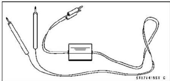
natural_image
Pure electrical circuit lines without any symbolsNeedleAdapterSet: 57001-1457

natural_image
Technical line drawing of two screwdriver tips (no text or symbols)ThrottleSensorSettingAdapter: 57001-1538

natural_image
Pure electrical connector diagram without any text, numbers, or symbolsSensorHarnessAdapter: 57001-1561

natural_image
Technical line drawing of a Y-shaped connector with multiple leads (no text or symbols)FuelPressureGaugeAdapter: 57001-1593

natural_image
Technical line drawing of a mechanical connector or fitting (no text or symbols)FuelHose: 57001-1607

natural_image
Two U-shaped metal pipe fittings with flanges, shown from different angles (no text or symbols)SpecialToolsandSealant
KawasakiBond(SiliconeSealant): 56019-120
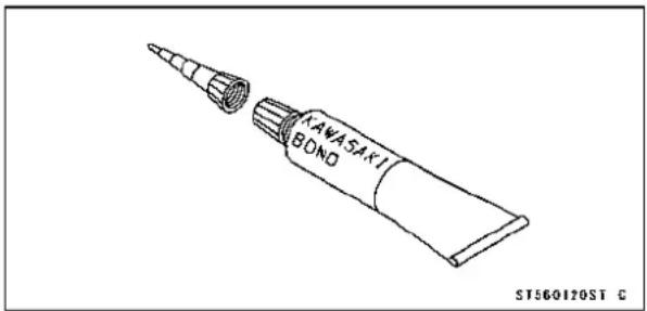
DFIServicingPrecautions
Thereareanumberofimportantprecautionsthatshould befollowedservicingtheDFIsystem.
○ThisDFIsystemisdesignedtobeusedwitha12Vsealed batteryasitspowersource.Donotuseanyotherbattery exceptfora12Vsealedbatteryasapowersource.
- Donotreversethebatterycableconnections. This will damagetheECU.
- TopreventdamagetotheDFIparts, donotdisconnectthe batterycablesoranyotherelectricalconnectionswhen theignitionswitchisonorwhiletheengineisrunning.
○Takecarenottoshorttheleadsthataredirectlyconnectedtothebatterypositive(+)terminaltothechassis ground.
○Whencharging,removethebatteryfromthemotorcycle. ThisistopreventECUdamagebyexcessivevoltage.
○DonotturntheignitionswitchONwhileanyoftheDFI electricalconnectorsaredisconnected.TheECUmemorizesservicecodes.
○Donotspraywaterontheelectricalparts,DFIparts,connectors,leads,andwiring.
○WhenevertheDFIelectricalconnectionsaretobedis-connected,firstturnofftheignitionswitch,anddisconnect thebattery(−)terminal.Donotpullthelead,onlytheconnector.Conversely,makesurethatalltheDFIelectrical connectionsarefirmlyreconnectedbeforestartingtheengine.
○Connecttheseconnectorsuntiltheyclick[A]
○Ifatransceiverisinstalledonthemotorcycle,makesure thattheoperationoftheDFIsystemisnotinfluencedby electricwaveradiatedfromtheantenna.Checkoperation ofthesystemwiththeengineatidle.Locatetheantenna asfaraspossibleawayfromtheECU.
Whenanyfuelhoseisdisconnected,fuelmayspoutout byresidualpressureinthefuelline.Coverthehosejoint withapieceofcleanclothopreventfuelspillage.
○Whenanyfuelhoseisdisconnected,donotturnonthe ignitionswitch.Otherwise,thefuelpumpwilloperateand fuelwillspoutfromthefuelhose.
○Donotoperatethefuelpumpifthepumpiscompletely dry. Thisistopreventpumpseizure.
○Beforeeremovingthefuelsystemparts, blowtheoutersurfacesofthesepartscleanwithcompressedair.
- Topreventcorrosionanddepositsinthefuelsystem,do notaddtofuelanyfuelantifreezechemicals.

DFIServicingPrecautions
- Tomaintainthecorrectfuel/airmixture(F/A),theremust benoinletairleaksintheDFIsystem.Besuretoinstall theoilfillerplug[A]afterfillingtheengineoil. ClutchCover[B]
Torque-OilFillerPlug:Hand-tighten

Outline
Outline
Whenanabnormalityinthesystemoccurs, theFlindicatorLED(LightEmittingDiode)lightgoesontoalerttherider onthemeterpanel. In addition, the condition of the problem is stored in the memory of the ECU (electronic control unit). With the engine stopped and turned in the self-diagnosis mode, the service code [A] is indicated by then number of times the FlindicatorLED lightblinks.
Whenduetoamalfunction, the FlindicatorLEDlightremainslit, asktheriderabouttheconditions[B]underwhich theproblemoccurredandtrytodeterminethecause[C].
- First, conduct as self-diagnosis inspection and then an non-self-diagnosis inspection. Then on self-diagnosis items are not indicated by the Fl indicator LED light. Don't rely solely on the DFI self-diagnosis function, use common sense.
EvenwhentheDFIsystemisoperatingnormally,theFI indicatorLEDlight[A]maylightupunderstrongelectrical interference.Norepairneeded.Turntheignitionswitch OFFtostoptheindicatorlight.
WhentheFlindicatorLEDlightgoesonandthemotorcycleisbroughtinforrepair,checktheservicecodes.
Whentherepairhasbeendone,theLEDlightdoesn'tgo on.Buttheservicecodesstoredinmemoryarenoterased topreservetheproblemhistory,andtheLEDlightcandis-playthecodesintheself-diagnosismode.Theproblem historyisreferredwhensolvingunstableproblems.
Whenthemotorcycleisdown,thevehicle-downsensoristurnedOFFandtheECUshutsoffthefuelinjectorsandignitionsystem.TheFlindicatorLEDlightblinksbuttheservicecodecannotbedisplayed.TheignitionswitchisleftON.Ifthestarterbuttonispushed,theelectricstarterturnsbuttheengineedsen'tstart.Tostarttheengineagain,raisethemotorcycle,turntheignitionswitchOFF,andthenON.Thevehicle-downsensoristurnedONandtheLEDlightgoesOFF.
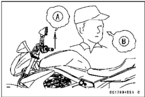


TroubleshootingtheDFISystem
○TheDFIpartconnectors[A]haveseals[B],includingthe ECU.
- Jointheconnectorandinserttheneedleadapters[C] insidetheseals[B]frombehindtheconnectoruntilthe adapterreachestheterminal.
SpecialTool-NeedleAdapterSet:57001-1457
CAUTION
Inserttheneedleaderstraightalongtheterminal intheconnectortopreventshort-circuitbetween terminals.
- Makesurethatmeasuringpointsarecorrectintheconnector, noting the position of the lock[D] and the lead color before measurement. Donot reverse connections of the hand tester or a digital meter.
- Becarefulnottoshort-circuittheleadsoftheDFlorelectricalsystempartsbycontactbetweenadapters.
- TurntheignitionswitchONandmeasurethevoltagewith theconnectorjoined.
CAUTION
Incorrect, reverseconnectionorshortcircuitby needleadapterscoulddamagetheDFlorelectrical systemparts.
○Aftermeasurement,removetheneedleadaptersandap- plysiliconesealanttotheseals[A]oftheconnector[B] forwaterproofing.
SiliconeSealant(KawasakiBond:56019-120)-Seals of Connector
- AlwayscheckbatteryconditionbeforereplacingtheDFI parts.Afullychargedbatteryisamustforconducting accuratetestsoftheDFIsystem.
- Troublemayinvolveoneorinsomecasesallitems. Neverreplaceadefectivepartwithoutdeterminingwhat CAUSEDtheproblem.Iftheproblemwascausedby someotheritemoritems,theytoomustberepairedor replaced,orthenewreplacementpartwillsoonfailagain.
- MeasurecoilwindingresistancewhentheDFIpartiscold (atroomtemperature).
- Makesureallconnectorsinthecircuitarecleanandtight, andexaminewiresforsignsofburning,fraying,short, etc.Deterioratedwiresandbadconnectionscancause reappearanceofproblemsandunstableoperationofthe DFIsystem.
★Ifanywiringisdeteriorated,replacethewiring.
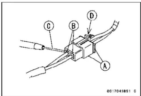

TroubleshootingtheDFISystem
- Pulleachconnector[A]apartandinspectitforcorrosion, dirt, and damage.
★Iftheconnectoriscorrodedordirty,cleanitcarefully.Ifit isdamaged,replaceit.Connecttheconnectorssecurely. - Checkthewiringforcontinuity.
○Usethewiringdiagramtofindtheendsoftheleadwhich issuspectedofbeingaproblem.
○Connectthehandtesterbetweentheendsoftheleads.
○Setthetestertothe×1Ω range,andreadthetester.
★Ifthetesterdoesnotread0Ω, theleadisdefective. Re-placetheleadorthemainharnessorthesubharness.
Olfbothendsofaharness[A]arefarapart,ground[B]the oneend[C],usingajumperlead[D]andcheckthecontinuitybetweentheend[E]andtheground[F].Thisenablestocheckalongharnessforcontinuity.Iftheharness isopen,repairorreplacetheharness.
Whencheckingaharness[A]forshortcircuit, openone end[B]andcheckthecontinuitybetweentheotherend [C]andground[D]. If thereiscontinuity, theharnesshas ashortcircuttoground, anditmustberepairedorreplaced.
- NarrowdownsuspiciouslocationsbyrepeatingthecontinuitytestsfromtheECUconnectors.
★Ifnoabnormalityisfoundinthewiringorconnectors,the DFIpartsarethenextlikelysuspects.Checkthepart, startingwithinputandoutputvoltages.However,thereis nowaytochecktheECUitself.
★Ifanabnormalityisfound,replaceaffectedDFIpart.
★Ifnoabnormalityisfoundinthewiring,connectors,and DFIparts,replaceECU.
○LeadColorCodes:
BK:Black
BL:Blue
BR:Brown
CH:Chocolate
DG:Darkgreen
G:Green
GY:Gray
LB:Lightblue
LG:Lightgreen
O:Orange
P:Pink
PU:Purple
R:Red
W:White
Y:Yellow
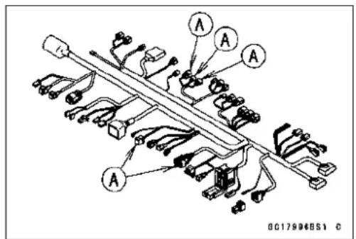

flowchart
graph TD
    A["A"] --> B["B"]
    B --> C["C"]
    C --> D["D"]
    D --> E["E"]
    E --> F["F"]
    F --> G["Ground Symbol"]
    style A fill:#f9f,stroke:#333
    style B fill:#f9f,stroke:#333
    style C fill:#f9f,stroke:#333
    style D fill:#f9f,stroke:#333
    style E fill:#f9f,stroke:#333
    style F fill:#f9f,stroke:#333
    style G fill:#f9f,stroke:#333
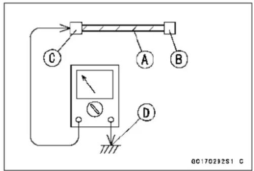
TroubleshootingtheDFISystem
- TherearetwowaystoinspecttheDFIsystem.Oneis voltageCheckMethodandtheotherisResistanceCheck Method.
(VoltageCheckMethod)
- This method is conducted by measuring the input voltage [B] to as sensor [A] first, and then the output voltage [C] from the sensor.
○SometimesthismethodcandetectafaultoftheECU.
- Refertoeachsensorinspectionsectionfordetailinthis chapter.
- Useafullychargedbatteryandadigitalmeter[D]which canbereadtwodecimalplacesvoltageorresistance.
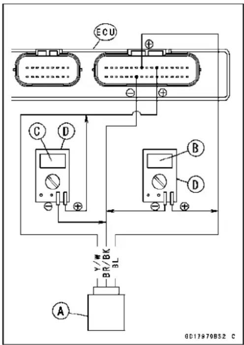
(ResistanceCheckMethod)
○Thismethodissimple.Noneedforafullychargedbattery andtheneedleadapter.Justdothefollowingsespecially whenasensor[A]issuspect.
- TurntheignitionswitchOFFanddisconnecttheconnectors.
- Inspectthesensorresistance, usingadigitalmeter(see eachsensorinspectioninthischapter).
- Inspectthewiringandconnectors[B]forcontinuity, using thehandtesterC rather thanadigital meter.
SpecialTool-HandTester:57001-1394
★ Ifthesensor, the wiring and connections are good, inspect the ECU for its ground and powers supply (seethis chapter). If the ground and powers supply are good, the ECU is suspect. Replace the ECU.

DFIDiagnosisFlowChart

flowchart
graph TD
    A["Problem occurs."] --> B["Confirm problems."]
    B --> C["Gather information from rider."]
    C --> D["The ignition switch is turned on, and the state of the FI indicator light (LED) is seen."]
    D --> E["unlit"]
    D --> F["lit"]
    E --> G["Conduct non-self-diagnosis inspection."]
    F --> H["Conduct self-diagnosis inspection."]
    G --> I["Conduct general fuel system inspection."]
    H --> J["End."]
    I --> J
    style A fill:#f9f,stroke:#333
    style J fill:#f9f,stroke:#333
InquiriestoRider
InquiriestoRider
○Eachriderreactstoproblemsindifferentways,soitisimportanttoconfirmwhatkindofsymptomstheriderhasencountered.
O Trytofindoutexactlywhatproblemoccurrendreunderexactlywhatconditionsbyaskingtherider; knowingthisinformationmayhelpyoureproducetheproblem.
○Thefollowingsamplediagnosisssheetwillhelppreventyoufromoverlookinganyareas,andwill helpyoudecideifitisaDFIsystemproblem,orageneralengineproblem.
TroubleshootingtheDFISystem
SampleDiagnosisSheet
| Ridername:RegistrationNo.(licenseplateNo.): | ||
| Yearofinitialregistration:Model: | ||
| EngineNo.:FrameNo.: | ||
| Dateproblemoccurred:Mileage: | ||
| Environmentwhenproblemoccurred. | ||
| Weather | □fine, □cloudy,□rain, □snow, □always, □other: | |
| Temperature | □hot, □warm, □cold, □very cold, □always | |
| Problem frequency | □chronic, □often, □once | |
| Road | □street, □highway, □mountain road (□uphill, □downhill), □bumpy, □pebble | |
| Altitude | □normal, □high (about 1 000 m or more) | |
| Motorcycleconditionswhenproblemoccurred. | ||
| Flindicator light(LED) | □light up immediately after ignition switch ON, and goes off after 1 ~ 2 seconds (normal) | |
| □lights blinks immediately after ignition switch ON, and stays on (DFI problem) | ||
| □lights up immediately after ignition switch ON, but goes off after about 10 seconds (DFIproblem) | ||
| □unlights(light(LED),ECUoritswiringfault) | ||
| □sometimeslightsup(probablywiringfault) | ||
| Starting difficulty | □startermotornotrotating | |
| □startermotorrotatingbutenginedoesn’tturnover | ||
| □startermotorandengine don’tturnover | ||
| □no fuel flow (□no fuel in tank, □no fuel pump sound) | ||
| □engine flooded (do not crank engine with throttle opened, which promotes engine flooding) | ||
| □nospark | ||
| □choke lever is not pulled fully when using the lever (pull it fully when using) | ||
| □other | ||
| Enginestops | □rightafterstarting | |
| □whenopeningthrottlegrip | ||
| □whenclosingthrottlegrip | ||
| □whenmovingoff | ||
| □whenstoppingthemotorcycle | ||
| □whencruising | ||
| □other | ||
| Poor running atlowspeed | □very low idle speed, □very high idle speed, □rough idle speed | |
| □batteryvoltageislow(chargethebattery) | ||
| □sparkplugloose(tightenit) | ||
| □sparkplugdirty, broken,orgapmaladjusted(remedyit) | ||
| □backfiring | ||
| □afterfiring | ||
| □hesitationwhenacceleration | ||
| □engineoilviscositytoohigh□brakedragging | ||
| □engineoverheating | ||
TroubleshootingtheDFISystem
| □clutchslipping | |
| □other | |
| Poorrunning ornopowerat highspeed | □sparkplugloose(tightenit) |
| □sparkplugdirty,broken,orgapmaladjusted(remedyit) | |
| □sparkplugincorrect(replaceit) | |
| □knocking (fuel poor quality or incorrect, → use high-octane gasoline) | |
| □brakedragging | |
| □clutchslipping | |
| □engineoverheating | |
| □engineoilleveltoohigh | |
| □engineoilviscositytoohigh | |
| □other |
DFISystemTroubleshootingGuide
NOTE
○This is not an exhaustive list, giving every possible cause for each problem listed. It is meant simplyasaroughguidetoassistthetroubleshootingforsomeofthemorecommandifficulties.
TheECUmaybeinvolvedintheDFIelectricalandignitionsystemtroubles.Ifthesepartsandcircuitsarecheckedoutgood,besuretochecktheECUforgroundandpowersupply.Ifthegroundandpowersupplyarecheckedgood,replacetheECU.
EngineDoesn'tStart, StartingDifficulty
| SymptomsorpossibleCausesActions(chapter) | |
| Startermotornotrotating: | |
| IgnitionandenginestopswitchesnotONTurnbothswitchesON. | |
| StarterlockoutswitchorneutralswitchtroubleInspect(seechapter16) | |
| StartermotortroubleInspect(seechapter16). | |
| Batteryvoltagelow | Inspectandcharge(seechapter16). |
| StarterrelaysnotcontactingoroperatingInspectthestarterrelay(seechapter16). | |
| StarterbuttonnotcontactingInspectandreplace(seechapter16). | |
| StartersystemwiringopenorshortedInspectthewiring(seechapter16). | |
| Ignitionswitchtrouble | Inspectandreplace(seechapter16). |
| Engine stop switch trouble | Inspect and repair or replace (see chapter 16). |
| Main 30A or ignition fuse blown | Inspect and replace (see chapter 16). |
| Startermotorrotatingbutengineedsn'tturnover: | |
| Starterclutchtrouble | Inspect(seechapter16). |
| Starteridlegeartrouble | Inspect(seechapter16). |
| Enginewon'tturnover: | |
| Valve seizure | Inspectandreplace(seechapter5). |
| Cylinder,pistonseizure | Inspectandreplace(seechapter5). |
| Camshaftseizure | Inspectandreplace(seechapter5). |
| Connectingrodsmallendseizure | Inspectandreplace(seechapter9). |
| Connectingrodbigendseizure | Inspectandreplace(seechapter9). |
| Crankshaftseizure | Inspectandreplace(seechapter9). |
| Transmissiongearorbearingseizure | Inspectandreplace(seechapter9). |
| Balancerbearingseizure | Inspectandreplace(seechapter9). |
| Nofuelflow: | |
| No or little fuel in tank | Supply fuel (see Owner's Manual). |
| Fuelpumpnotrotating | Inspect(seechapter3). |
| Fuelinjectortrouble | Inspectandreplace(seechapter3). |
| Fueitankairventobstructed | Inspectandrepair(seechapter3). |
| Fuel filter or pump screen clogged | Inspect and replace fuel pump (see chapter 3). |
| Fuel pressure regulator clogged | Inspect and replace fuel pump (see chapter 3). |
| Fuellineclogged | Inspectandrepair(seechapter3). |
| Engineflooded: | |
| Spark plug dirty, broken or gap maladjusted | Replace (see chapter 2). |
| Starting technique faulty | When flooded, don't crank engine with throttle fullyopened. |
| Nosparkorsparkweak: | |
| IgnitionandenginestopswitchesnotONTurnbothswitchesON. | |
DFISystemTroubleshootingGuide
| SymptomsorpossibleCausesActions(chapter) | |
| Clutchlevernotpulledinandgearnotinneutralwhethersidestandupornot | Pulltheleverinandshiftthegearinneutral. |
| Thoughclutchleverpulledin,sidestandupand gearnotinneutral | Sidestanddownandclutchleverpulledin whethergearinneutralornot |
| Vehicle-down-sensorcomingoffReinstall(seechapter3). | |
| Vehicle-down-sensortroubleInspect(seechapter3). | |
| ECUgroundorpowersupplytroubleInspect(seechapter3). | |
| BatteryvoltagelowInspectandcharge(seechapter16). | |
| Sparkplugdirty,brokenorgapmaladjustedReplace(seechapter2). | |
| StickcoiltroubleInspectstickcoil(seechapter16). | |
| StickcoilshortedornotingoodcontactReinstallorinspectstickcoil(seechapter16). | |
| SparkplugincorrectReplaceitwiththecorrectplug(seechapter16). | |
| ICigniterinECUtrouble Inspect(seechapter16). | |
| Neutral,starterlockoutorsidestandswitch trouble | Inspecteachswitch(seechapter16). |
| Crankshaftsensortrouble Inspect(seechapter16). | |
| StickcoiltroubleInspect(seechapter16). | |
| Ignitionswitchshorted Inspectandreplace(seechapter16). | |
| Engine stop switch shorted | Inspect and repair or replace (see chapter 2) . |
| Starter system wiring shorted or open | Inspect and repair or replace (see chapter 16). |
| Main30Aorignitionfuseblown Inspectandreplace(seechapter16). | |
| Fuel/airmixtureincorrect: | |
| Aircleanerclogged,poorlysealedormissing | Cleanorreinstall(seechapter3). |
| Leakfromoilfillercap,crankcasebreatherhose oraircleanerdrainhose | Inspectandrepairorreplace(seechapter3). |
| Water or foreign matter in fuel | Change fuel. Inspect and clean fuel system (see chapter3). |
| Fuelpressureregulatortrouble Inspectfuelpressureandreplacefuelpump(see chapter3). | |
| Mainthrottlesensortrouble Inspect(seechapter3). | |
| FuelpressuremaybelowInspect(seechapter3). | |
| Fuelpumptrouble Inspect(seechapter3). | |
| Fuelinjectortrouble Inspect(seechapter3). | |
| Inletairpressuresensortrouble Inspect(seechapter3). | |
| Inletairtemperaturesensortrouble Inspect(seechapter3). | |
| Water temperature sensor trouble Inspect (see chapter 3). | |
| Crankshaftsensortrouble Inspect(seechapter3). | |
| Compressionlow: | |
| Sparkplugloose Reinstall(seechapter16). | |
| Cylinder head not sufficiently tightened down Tighten (see chapter 5). | |
| Cylinder,pistonworn Inspectandreplace(seechapter5). | |
| Piston ring bad (worn, weak, broken or sticking) Inspect and replace (see chapter 5). | |
| Piston ring/groove clearance excessive Inspect and replace (see chapter 5). | |
| Cylinderheadgasketdamaged Replace(seechapter5). | |
| Cylinder head warped Inspect and replace (see chapter 5). | |
DFISystemTroubleshootingGuide
| SymptomsorpossibleCausesActions(chapter) | |
| NovalveclearanceAdjust(seechapter2). | |
| Valveguideworn | Inspectandreplace(seechapter5). |
| ValvespringbrokenorweakInspectandreplace(seechapter5). | |
| Valvenotseatingproperly(valvebent,wornor carbonaccumulatingonseatingsurface) | Inspectandrepairorreplace(seechapter5). |
PoorRunningatLowSpeed
| SymptomsorPossibleCausesActions(chapter) | |
| Sparkweak: | |
| BatteryvoltagelowInspectandcharge(seechapter16). | |
| Sparkplugdirty,brokenorgapmaladjustedReplace(seechapter2). | |
| StickcoiltroubleInspectthestickcoil(seechapter16). | |
| StickcoilshortedornotingoodcontactReinstallerinspectstickcoil(seechapter16). | |
| SparkplugincorrectReplaceitwiththecorrectplug(seechapter16). | |
| IC igniter in ECU trouble | Inspect (see chapter 16). |
| Crankshaftssensortrouble | Inspect(seechapter16). |
| StickcoiltroubleInspect(seechapter16). | |
| Fuel/airmixtureincorrect: | |
| Little fuel in tank | Supply fuel (see Owner's Manual). |
| Air cleaner clogged, poorly sealed, or missing | Clean element or inspect sealing (see chapter 2,3). |
| Aircleanerductloose | Reinstall(seechapter3). |
| Air cleaner O-ring damaged | Replace (see chapter 3). |
| FueItankairventobstructed | Inspectandrepair(seechapter3). |
| Throttlebo dyassyloose | Reinstall(seechapter3). |
| ThrottlebodyassyO-ringdamage | Replace(seechapter3). |
| Fuel filter or pump screen clogged | Inspect and replace fuel pump (see chapter 3). |
| Fuelpressureregulatorclogged | Inspectfuelpressureandreplacefuelpump(seechapter3). |
| Fuellineclogged | Inspectandrepair(seechapter3). |
| Inletairpressuresensortrouble | Inspect(seechapter3). |
| Inletairtemperaturesensortrouble | Inspect(seechapter3). |
| Thermostattrouble | Inspectandreplace(seechapter4). |
| Unstable(rough)idling: | |
| Fuelinjectortrouble | Inspect(seechapter3). |
| Mainthrottlesensortrouble | Inspect(seechapter3). |
| Crankshaftssensortrouble | Inspect(seechapter3). |
| Throttlevalvesnotsynchronizing | Inspect(seechapter2). |
| Inletairtemperaturesensortrouble | Inspect(seechapter3). |
| Watertemperaturesensortrouble | Inspect(seechapter3). |
| Fuelpressuretoolowortoohigh | Inspect(seechapter3). |
| BatteryvoltagelowInspectandcharge(seechapter16). | |
| Incorrectidespeed: | |
| Water temperature sensor trouble | Inspect (see chapter 3). |
| Mainthrottlesensortrouble | Inspect(seechapter3). |
DFISystemTroubleshootingGuide
| SymptomsorPossibleCausesActions(chapter) | |
| Enginestallseasily: | |
| Fuelpumptrouble | Inspect(seechapter3). |
| FuelinjectortroubleInspect(seechapter3). | |
| MainthrottlesensortroubleInspect(seechapter3). | |
| FuelpressuretoolowortoohighInspect(seechapter3). | |
| InletairpressuresensortroubleInspect(seechapter3). | |
| WatertemperaturesensortroubleInspect(seechapter3). | |
| Inletairtemperaturesensortrouble | Inspect(seechapter3). |
| FuellinecloggedInspectandrepair(seechapter3). | |
| FuelpressuretoolowortoohighInspect(seechapter3). | |
| Fuel pressure regulator trouble | Inspect fuel pressure and replace fuel pump (see chapter3). |
| Crankshaftsensortrouble | Inspect(seechapter16). |
| Stickcoiltrouble | Inspect(seechapter16). |
| CompressionLow: | |
| Sparkplugloose | Reinstall(seechapter16). |
| Cylinder head not sufficiently tightened down | Tighten (see chapter 5). |
| Novalveclearance | Adjust(seechapter2). |
| Cylinder,pistonworn | Inspectandreplace(seechapter5). |
| Piston ring bad (worn, weak, broken or sticking ) | Inspect and replace (see chapter 5). |
| Piston ring/groove clearance excessive | Inspect and replace (see chapter 5). |
| Cylinderheadgasketdamaged | Replace(seechapter5). |
| Cylinderheadwarped | Inspectandreplace(seechapter5). |
| Valve guide worn or stem seal damaged | Inspect and replace (see chapter 5). |
| Valve spring broken or weak | Inspect and replace (see chapter 5). |
| Valvenotseatingproperly(valvebent,wornor carbon accumulatingonseatingsurface) | Inspect and repair or replace (see chapter 5). |
| Camshaftcamworn | Inspectandreplace(seechapter5). |
| Hesitation: | |
| Too low fuel pressure | Inspect (see chapter 3). |
| Cloggedfuelline | Inspectandrepair(seechapter3). |
| Crackedorobstructedinletairpressuresensor hose | Inspect and repair or replace (see chapter 3). |
| Fuelpumptrouble | Inspect(seechapter3). |
| FuelinjectortroubleInspect(seechapter3). | |
| Inletairtemperaturesensortrouble | Inspect(seechapter3). |
| MainthrottlesensortroubleInspect(seechapter3). | |
| Subthrottlesensortrouble | Inspect(seechapter3). |
| Subthrottlevalveactuatortrouble | Inspect(seechapter3). |
| WatertemperaturesensortroubleInspect(seechapter3). | |
| InletairpressuresensortroubleInspect(seechapter3). | |
| Looseinjectorconnectors | Remedy(seechapter3). |
| Crankshaft sensor trouble | Inspect and repair or replace (see chapter 16). |
| Stick coil trouble | Inspect and repair or replace (see chapter 16). |
DFISystemTroubleshootingGuide
| SymptomsorPossibleCausesActions(chapter) | |
| Looseterminalofbattery(−)leadorengine groundlead | Inspectandrepair(seechapter16). |
| DelayofignitiontimingInspectcrankshaftsensorand | CigniterinECU (seechapter16). |
| Pooracceleration: | |
| ToolowfuelpressureInspect(seechapter3). | |
| WaterorforeignmatterinfuelChangefuel.Inspectandcleanfuelsystem(see chapter3). | |
| CloggedfuelfilterorpumpscreenInspectandreplacefuelpump(seechapter3). | |
| FuelpumptroubleInspect(seechapter3). | |
| FuelinjectortroubleInspect(seechapter3). | |
| Inletairtemperaturesensortrouble | Inspect(seechapter3). |
| Watertemperaturesensortrouble | Inspect(seechapter3). |
| Subthrottlesensortrouble | Inspect(seechapter3). |
| Subthrottlevalveactuatortrouble | Inspect(seechapter3). |
| Stickcoiltrouble | Inspectandreplace(seechapter16). |
| EngineoilleveltohighRepair(seechapter7). | |
| Spark plug dirty, broken or gap maladjusted | Replace (see chapter 2). |
| Stumble: | |
| ToolowfuelpressureInspect(seechapter3). | |
| FuelinjectortroubleInspect(seechapter3). | |
| Mainthrottlesensormalfunction | Inspect(seechapter3). |
| Subthrottlesensortrouble | Inspect(seechapter3). |
| Subthrottlevalveactuatortrouble | Inspect(seechapter3). |
| Watertemperaturesensortrouble | Inspect(seechapter3). |
| Inletairpressuresensortrouble | Inspect(seechapter3). |
| Surge: | |
| Unstablefuelpressure | Fuelpressureregulatorortrouble(Inspectand replacefuelpump)orkinkedfuelline(Inspect andrepairfuelline)(seechapter3). |
| FuelinjectortroubleInspect(seechapter3). | |
| Watertemperaturesensortrouble | Inspect(seechapter3). |
| Backfiringwhendeceleration: | |
| Spark plug dirty, broken or gap maladjusted | Replace (see chapter 2). |
| ToolowfuelpressureInspect(seechapter3). | |
| FuelpumptroubleInspect(seechapter3). | |
| Mainthrottlesensortrouble | Inspect(seechapter3). |
| Inletairtemperaturesensortrouble | Inspect(seechapter3). |
| Watertemperaturesensortrouble | Inspect(seechapter3). |
| Inletairpressuresensortrouble | Inspect(seechapter3). |
| Airswitchingvalvebroken | Inspectandreplace(seechapter5). |
| Airsuctionvalvetrouble | Inspectandreplace(seechapter5). |
| Afterfire: | |
| Crankshaftsensortrouble | Inspect(seechapter16). |
| Spark plug burned or gap maladjusted | Replace (see chapter 2). |
DFISystemTroubleshootingGuide
| SymptomsorPossibleCausesActions(chapter) | |
| InletairtemperaturesensortroubleInspect(seechapter3). | |
| WatertemperaturesensortroubleInspect(seechapter3). | |
| InletairpressuresensortroubleInspect(seechapter3). | |
| FuelinjectortroubleInspect(seechapter3). | |
| Run-on(dieseling): | |
| IgnitionswitchtroubleInspectandreplace(seechapter16). | |
| EnginestopswitchtroubleInspectandrepairorreplace(seechapter2). | |
| FuelinjectortroubleInspect(seechapter3). | |
| Looseterminalofbattery(-)cableorECU groundlead | Inspectandrepair(seechapter16). |
| CarbonaccumulatingonvalveseatingsurfaceRepair(seechapter5). | |
| Engineoverheating | (seeOverheatingofTroubleshootingGuide,see chapter17) |
| Other: | |
| Engineoilviscositytoohigh Change(seechapter2). | |
| Drivetraintrouble | Inspectdrivechain(seechapter2)andsprocket (seechapter11). |
| Brakedragging | Inspectcaliperfluidsealdamageorclogging ofmastercylinderreliefandsupplyports(see chapter12). |
| Clutchslipping | Inspectfrictionplatesforwear(seechapter6). |
| Engineoverheating | (seeOverheatingofTroubleshootingGuide,see chapter17) |
| Airswitchingvalvetrouble | Inspectandreplace(seechapter5). |
| Airsuctionvalvetrouble | Inspectandreplace(seechapter5). |
| Intermittent any DFI fault and its recovery | Check that DFI connectors are clean and tight, andexaminewiresforsignsofburningorfraying (seechapter3). |
PoorRunningorNoPoweratHighSpeed:
| SymptomsorPossibleCausesActions(chapter) | |
| Firingincorrect: | |
| Sparkplugdirty,brokenormaladjusted | Replace(seechapter2). |
| Stickcoiltrouble | Inspectstickcoil(seechapter16). |
| Stick coil shorted or not in good contact | Reinstall or inspect stick coil (see chapter 16). |
| Spark plug incorrect | Replace it with the correct plug (see chapter 16). |
| ICigniterinECUtrouble | Inspect(seechapter16). |
| Crankshaftsensortrouble | Inspect(seechapter16). |
| Stickcoiltrouble | Inspect(seechapter16). |
| Fuel/airmixtureincorrect: | |
| Air cleaner clogged, poorly sealed, or missing | Clean element or inspect sealing (see chapter 3). |
| Aircleanerductloose | Reinstall(seechapter3). |
| AircleanerO-ringdamaged | Replace(seechapter3). |
| Water or foreign matter in fuel | Change fuel. Inspect and clean fuel system (see chapter3). |
| Throttlebodyassyloose | Reinstall(seechapter3). |
DFISystemTroubleshootingGuide
| SymptomsorPossibleCausesActions(chapter) | |
| ThrottlebodyassyO-ringdamagedReplace(seechapter3). | |
| Fueltankairventobstructed | Inspectandrepair(seechapter3). |
| FuellinecloggedInspectandrepair(seechapter3). | |
| FuelpumpoperatesintermittentlyandoftenDFI fuseblows. | Pumpbearingsmaywear.Replacehepump(seechapter3). |
| FuelpumptroubleInspect(seechapter3). | |
| InletairtemperaturesensortroubleInspect(seechapter3). | |
| MainthrottlesensortroubleInspect(seechapter3). | |
| InletairpressuresensortroubleInspect(seechapter3). | |
| Crackedorobstructedinletairpressuresensor hose | Inspectandrepairorreplace(seechapter3). |
| Injectorclogged | Visuallyinspectandreplace(seechapter3). |
| Compressionlow: | |
| Sparkplugloose | Reinstall(seechapter16). |
| Cylinderheadnotsufficientlytighteneddown | Tighten(seechapter5). |
| Novalveclearance | Adjust(seechapter2). |
| Cylinder,pistonworn | Inspectandreplace(seechapter5). |
| Piston ring bad (worn, weak, broken or sticking) | Inspect and replace (see chapter 5). |
| Piston ring/groove clearance excessive | Inspect and replace (see chapter 5). |
| Cylinder head gasket damaged | Replace (see chapter 5). |
| Cylinderheadwarped | Inspectandreplace(seechapter5). |
| Valvespringbrokenorweak | Inspectandreplace(seechapter5). |
| Valvenotseatingproperly(valvebent,wornor carbonaccumulatingontheseatingsurface) | Inspectandrepairorreplace(seechapter5). |
| Knocking: | |
| Carbonbuiltupincombustionchamber | Repair(seechapter5). |
| Fuelpoorqualityorincorrect(Usethegasoline recommendedintheOwner'sManual) | Changefuel(seechapter3). |
| Sparkplugincorrect | Replaceitwiththecorrectplug(seechapter16). |
| Stickcoiltrouble | Inspect(seechapter16). |
| ICigniterinECUtrouble | Inspect(seechapter16). |
| InletairtemperaturesensortroubleInspect(seechapter3). | |
| Miscellaneous: | |
| Subthrottlesensortrouble | Inspect(seechapter3). |
| Subthrottlevalveactuatortrouble | Inspect(seechapter3). |
| Speedsensortrouble | Inspect(seechapter3). |
| Throttlevalveswon'tfullyopen | Inspectthrottlecableandleverlinkage(see chapter3). |
| Brakedragging | Inspectcaliperfluidsealdamageorclogging ofmastercylinderreliefandsupplyports(see chapter12). |
| Clutchslipping | Inspectfrictionplatesforwear(seechapter6). |
| Engineoverheating-Watertemperaturesensor, crankshaftsensororspeedsensortrouble | (seeOverheatingofTroubleshootingGuidein chapter17). |
| Engineoilleveltoohigh | Repair(seechapter7). |
| Engineoilviscositytoohigh | Change(seechapter2). |
DFISystemTroubleshootingGuide
| SymptomsorPossibleCausesActions(chapter) | |
| Drivetraintrouble | Inspectdrivechain(seechapter2)andsprockets (seechapter11). |
| CamshaftcamwornInspectandreplace(seechapter5). | |
| AirswitchingvalvetroubleInspectandreplace(seechapter5). | |
| AirsuctionvalvetroubleInspectandreplace(seechapter5). | |
| Catalyticconvertersmeltdownduetomuffler overheating | Replacemuffler(seechapter5). |
| ExhaustSmokesExcessively: | |
| (Whitesmokes) | |
| PistonoilringwornInspectandreplace(seechapter5). | |
| CylinderwornInspectandreplace(seechapter5). | |
| ValveoilsealdamagedReplace(seechapter5). | |
| Valveguidewom | Replacetheguide(seechapter5). |
| Engineoilleveltoohigh | Repair(seechapter7). |
| (Blacksmoke) | |
| Aircleanerclogged | Clean(seechapter3). |
| Too high fuel pressure | Inspect (see chapter 3). |
| Injectorstuckopen | Inspect(seechapter3). |
| Water temperature sensor trouble | Inspect and replace (see chapter 3). |
| Inlet air temperature sensor trouble | Inspect and replace (see chapter 3). |
| (Brownsmoke) | |
| Aircleanerductloose | Reinstall(seechapter3). |
| AircleanerO-ringdamaged | Replace(seechapter3). |
| Too low fuel pressure | Inspect fuel line and fuel pump (see chapter 3). |
| Water temperature sensor trouble | Inspect and replace (see chapter 3). |
| Inlet air temperature sensor trouble | Inspect and replace (see chapter 3) |
Self-Diagnosis
Self-diagnosisOutline
Self-diagnosisOutline
Theself-diagnosisssystemhasthreemodesandcanbe switchedtoanothermodebygroundingtheself-diagnosis terminal.
UserMode
TheECUnotifiestherideroftroublesinDFIsystemandignitionsystembylightingtheFlindicatorwhenDFIsystemandignitionsystempartsarefaulty,andinitiatesfail-safe function.Incaseofseriousoustroubles,theECUstopsthe injection/ignition/startermotoroperation.
DealerMode1
TheFlindicatorlight(LED)emitsservicecode(s)toshow theproblem(s)whichtheDFIsystem,andignitionsystem hasatthemomentofdiagnosis.
DealerMode2
TheFlindicatorlight(LED)emitsservicecode(s)toshow theproblem(s)whichtheDFIsystem,andignitionsystem hadinthepast.
Self-diagnosis Procedures
Self-diagnosis Procedures
When a problem occurs with the DFIsystem and ignition system, the DFI indicator light(LED)[A] goes on.
NOTE
○Useafullychargedbatterywhenconducting self-diagnosis. Otherwise, thelight(LED)blinks veryslowlyordoesn'tblink.
○Keeptheself-diagnosisterminalgroundedduringself-diagnosis, withanauxiliarylead.
- Removetheseat(seeSeatRemovalintheFramechapter).
- Ground[A]theself-diagnosisterminalBtothebattery(−)terminal[C]orbattery(−)leadconnector,usingawire.
- Turnontheignitionswitch.
- Connectanauxiliarylead[E]totheself-diagnosisterminal [G]forgrounding.
- Toentertheself-diagnosisdealermode1,ground[A]the self-diagnosisindicatorterminaltothebattery(−)terminal formorethan2seconds[C],andthenkeepitgrounded continuously[D].
○Count the blinks of the light (LED) to read the service code. Keep the auxiliary leadground until you finish reading the service code.

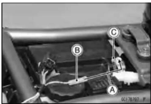

Self-Diagnosis
- Toentertheself-diagnosisdealermode2, open[B] and ground[A] theleadmorethanfivetimes[F] within2seconds[C] aftertheleadisfirstgrounded, and then keepit grounded continuously[D] formorethan2seconds.
○Counttheblinksofthelight(LED)toreadtheservice code.Keeptheauxiliaryleadgrounduntilyoufinishreadingtheservicecode.
AuxiliaryLead[E]
Self-diagnosisTerminal[G]
NOTE
○ Toenterthedealermode2fromthedealermode1,turn offtheignitionswitchonce.
ServiceCodeClearingProcedures
ServiceCodeClearingProcedures
- Entertheself-diagnosisdealermode2(seeSelf-diagnosisProceduresinthischapter).
NOTE
○ Makesuretokeepthegroundinguntilthefollowing openingandgroundingstarts.
- Pulltheclutchleverinmorethan5seconds, and then releaseit.
- Repeatopening[B]andgrounding[A]thelead (self-diagnosisterminal)morethanfivetimes[F]within2 seconds[C]aftertheleadisgrounded,andthenkeepit groundedcontinuously[D]formorethan2seconds.
AuxiliaryLead[E]
Self-diagnosisTerminal[G]
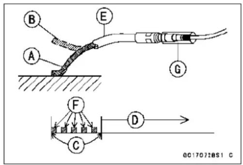

Self-Diagnosis

flowchart
graph TD
    A["Turn the ignition switch OFF"] --> B["Turn the ignition switch ON, and self-diagnosis mode starts, using an auxiliary lead."]
    B --> C["Dealer Mode 1.<br>Ground the self-diagnosis terminal for more than 2 seconds and then keep it grounded."] --> D["FI indicator light (LED) blinks to display the service code for more than 2 seconds."]
    B --> E["Dealer Mode 2.<br>Ground and open the self-diagnosis terminal more than five times within 2 seconds and then keep it grounded."] --> D
    D --> F["Locate the problem with the service code table and check and repair DFI or ignition system according to inspection procedure on all service codes."]
    F --> G["Remove the auxiliary lead, ending the self-diagnosis mode."]
    G --> H["Make sure the FI indicator light (LED) doesn't go ON."]
    H -->|NG| I["End"]
    H -->|NG| J["Run the engine for several minutes at idling and run the motorcycle at 30 km/h (18 mph) or above in order to confirm no problem."]
    J --> K["OK"]
    K --> L["END"]
HowtoReadServiceCodes
HowtoReadServiceCodes
○ServicecodesareshownbyaseriesoflongandshortblinksoftheFlindicatorlight(LED)asshown below.
○Read10thdigitandunitdigitastheFlindicatorlight(LED)blinks.
○Whenthereareanumberofproblems,alltheservicecodescanbestoredandthedisplaywill beginstartingfromthelowestnumberservicecodeinthenumericalorder. Thenaftercompleting allcodes,thedisplayisrepeateduntiltheself-diagnosisindicatorterminalisopen.
○Ifthereisnoproblem,nocodeandunlight.
○Forexample,iftwoproblemsoccurredintheorderof21,12,theservicecodesaredisplayedfrom the lowestnumberintheorderlisted.
$$ (1 2 \rightarrow 2 1) \rightarrow (1 2 \rightarrow 2 1) \rightarrow \dots (\text { repeated }) $$

Of the problem is with the following parts, the ECU cannot memorize these problems, the Fl indicator light(LED) doesn't goon, and noservice codes can be displayed.
FllIndicatorLight(LED)
FuelPump
FuelPumpRelay
DFIMainRelay
ECUPowerSourceWiringandGroundWiring(seeECUInspection)
FuelInjectors
HowtoEraseServiceCodes
HowtoEraseServiceCodes
○EveniftheignitionswitchisturnedOFF,thebatteryortheECUaredisconnectedortheproblemis solved,allservicecodesremainintheECU.
○RefertotheServiceCodeClearingProcedurefortheservicecodeerasure.
Self-Diagnosis
ServiceCodeTable
ServiceCodeTable
| Service Code | FllndicatorLEDLightProblems | |
| 11 |   | Mainthrottlesensormalfunction,wiringopenorshort |
| 12 | [22AB] | Inletairpressuresensormalfunction,wiringopenorshort |
| 13 | [30TT] | Inletairtemperaturesensormalfunction,wiringopenorshort |
| 14 |  | Watertemperaturesensormalfunction,wiringopenorshort |
| 21 | 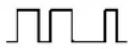 | Crankshaftsensormalfunction,wiringopenorshort |
| 24 and 25 |  +[ZZDH] +[ZZDH] | Speedsensormalfunction,wiringopenorshortFirst24isdisplayedandthen25,repeatedly |
| 31 | [5HZK] | Vehicle-downsensor,malfunction,wiringopenorshort |
| 32 | [4003] | Subthrottlesensormalfunction,wiringopenorshort |
| 33 | [8KB4] | Oxygensensorinactivation,wiringopenorshort(EuropeModel) |
| 51 |  | Stick(Ignition)coil#1malfunction,wiringopenorshort |
| 52 | [0ZA3] | Stick(Ignition)coil#2malfunction,wiringopenorshort |
| 56 | [ZZD3] | Radiatorfanrelaymalfunction,wiringopenorshort |
| 62 |  | Subthrottlevalveactuatormalfunction,wiringopenorshort |
| 64 | [KS43] | Airswitchingvalvemalfunction,wiringopenorshort |
| 67 | [KA05] | Oxygensensorheatermalfunction,wiringopenorshort(EuropeModel) |
| 94 |  | Oxygensensormalfunction,wiringopenorshort(EuropeModel) |
Notes:
The ECU maybe involved in these problems. If all the parts and circuits checked out good, be sure to check the ECU for ground and powers supply. If the ground and powers supply are checked good, replace the ECU.
○Whennoservicecodeisdisplayed, the electrical part of the DFIsystem has no fault, and the mechanical part of the DFIsystem and the enginearesuspect.
Backups
Backups
○TheECUtakesthefollowingmeasurestopreventenginedamagewhentheDFIortheignition systempartshavetroubles.
| Service Codes | Parts | OutputSignalUsable RangeorCriteria | BackupsbyECU |
| 11 | MainThrottle Sensor | MainThrottleSensor OutputVoltage 0.20~4.8V | Ifthemainthrottlesensorsystemfails(the signalisoutoftheusablerange,wiringshort oropen),theECUlocksignitiontimingintothe ignitiontimingatclosedthrottlepositionand setstheDFlintheD-Jmethod.Also,themainthrottlesensorsystemmand inletairpressurefails,theECUlocksignition timingintotheignitiontimingatclosedthrottle positionandsetstheDFlintheα-Nmethod. |
| 12 | InletAir Pressure Sensor | InletAirPressure (absolute)Pv=150mmHg~800 mmHg | Iftheinletairpressuresensorsystemfails(the signalPvisoutoftheusablerange,wiring shortoropen),theECUsetstheDFlintheα-Nmethod. |
| 13 | InletAir Temperature Sensor | InletAirTemperature Ta=-30°C~+120°C | Iftheinletairtemperaturesensorfails(the signalisoutoftheusablerange,wiringshort oropen),theECUsetsTaat40°C. |
| 14 | Water Temperature Sensor | WaterTemperature Tw=-30C°~+120°C | Ifthewatertemperaturesensorsystemfails (thesignalisoutoftheusablerange,wiring shortoropen),theECUsetsTwat80°C. |
| 21 | Crankshaft Sensor | Crankshaftsensormust send22signals(output signal)totheECUat theonecranking. | Ifcrankshaftsensorgeneratesotherthan22 signals,theenginestopsbyitself. |
| 24 and 25 | SpeedSensor | Speedsensormust send4signals(output signal)totheECUat theonerotationofthe enginesprocket.Thegearpositionis decidedbythesignalof thespeedsensor. | Ifthespeedsensorsystemfails(nosignal, wiringshortoropen),thespeedometershows 0,andtheECUsetsthetop(6)gearposition. |
| 31 | Vehicle-down Sensor | Vehicle-downSensor OutputVoltage(signal)Vd=0.65V~4.45V | Ifthevehicle-downsensorsystemhasfailures (theoutputvoltageVdismorethanusable range,wiringopen),theECUshutsoffthe fuelpump,thefuelinjectorsandtheignition system. |
| 32 | Subthrottle Sensor | SubthrottleSensor OutputVoltage 0.15~4.85V | Ifthesubthrottlesensorsystemfails(the signalisoutoftheusablerange,wiringshort oropen),theactuatorlockssubthrottlevalve atfullopenposition. |
| 33 | OxygenSensor (EuropeModel) | Theoxygenensoris activeandsensormust sendsignals(output voltage)continuously to theECU. | Iftheoxygensensorisnotactivated,theECU stopsoygensensorfeedbackmode. |
Self-Diagnosis
| Service Codes | Parts | OutputSignalUsable RangeorCriteria | BackupsbyECU |
| 51 | StickCoil#1 (IgnitionCoil)* | Thestickcoilprimary windingmustsend signals(outputvoltage) continuouslytothe ECU. | Iftheignitionprimarywinding#1hasfailures (nosignal,wiringshortoropen),theECU shutsofftheinjector#1tostopfueltothe cylinder#1,thoughtheenginekeepsrunning. |
| 52 | StickCoil#2 (IgnitionCoil)* | Thestickcoilprimary windingmustsend signals(outputvoltage) continuouslytothe ECU. | Iftheignitionprimarywinding#2hasfailures (nosignal,wiringshortoropen),theECU shutsofftheinjector#2tostopfueltothe cylinder#2,thoughtheenginekeepsrunning. |
| 62 | Subthrottle ValveActuator | Theactuatoroperates openandcloseofthe subthrottlevalvebythe pulsesignalfromthe ECU. | Ifthesubthrottlevalveactuatorfails(the signalisoutoftheusablerange,wiringshort oropen),theECUstopsthecurrenttothe actuator. |
| 67 | OxygenSensor (EuropeModel) | Theoxygenensor heaterraise temperatureofthe sensorforitsearlier activation.12V-6.6W, 0.55A | Iftheoxygenensorheaterfails(wiringshort oropen),theECUstopsthecurrenttothe heater. |
| 94 | OxygenSensor (EuropeModel) | Theoxygensensor mustsendsignals (outputvoltage) continuouslytothe EUC | Iftheoxygenensoroutputvoltageisincorrect, theECUstopsoygensensorfeedbackmode. |
Note:
(1) D-J Method and -N Method: When the engine load is light like at idling or low speed, the ECU determinestheinjectionquantitybycalculatingfromthethrottlevacuum(inletairpressuresensor outputvoltage)andenginespeed(crankshaftsensoroutputvoltage).ThismethodiscalledD-J method(low-speedmode).Astheenginespeedincreases,andtheengineloadturnsmiddleto heavy,theECUdeterminestheinjectionquantitybycalculatingfromthethrottleopening(throttle sensor output voltage) and the engine speed. This method is called -N method (high-speed mode).
(*) This depends on the number of stopped cylinders.
MainThrottleSensorRemoval/Adjustment
CAUTION
Donotremoveoradjustthemainthrottlesensor[A] sinceithasbeenadjustedandsetwithprecisionat thefactory.
Neverdropthesensor,especiallyonahardsurface.
Suchashocktothesensorcandamageit.
Input Voltage Inspection
NOTE
○ Besurethebatteryisfullycharged.
- TurntheignitionswitchOFF.
- Disconnectthemainthrottlesensorconnectorandconnecttheharnessadapter[A]betweentheseconnectors.
- Connectadigitalmetertotheharnessadapterlead.
SpecialTool-ThrottleSensorHarnessAdapter:57001-1538
- Measurethesensorinputvoltagewiththeenginestopped andwiththeconnectorjoined.
- TurntheignitionswitchON.
MainThrottleSensorInputVoltage ConnectionstoAdapter
Meter(+)→ R(sensorBL)lead
Meter(-)→ BK(sensorBR/BK)lead
Standard:4.75\~5.25VDC
- TurntheignitionswitchOFF.
★Iftheinputvoltageisnormal,checkthesensoroutput voltage.
★Iftheinputvoltageislessthanthestandard,removethe ECUandcheckthewiringbetweentheseconnectors.
○DisconnecttheECUandsensorconnectors.
WiringConnection
ECUConnector[A]←→ ThrottleSensorConnector[B]
BLlead(ECUterminal10)
BR/BKlead(ECUterminal28)
★Ifthewiringisgood,checktheECUforitsgroundand powersupply(seeECUPowerSupplyInspection).

natural_image
Close-up mechanical assembly showing a component labeled 'A' and part identifier 'GC178673 P' (no readable text or symbols beyond labels)
natural_image
Close-up mechanical assembly showing hoses and components (no visible text or symbols)
MainThrottleSensor(ServiceCode11)
OutputVoltageInspection
- Measure the output voltage at the main throttlesensor in the same way as input voltage inspection, Not the following.
- Disconnectthemainthrottlesensorconnectorandconnecttheharnessadapter[A]betweentheseconnectors.
SpecialTool-ThrottleSensorHarnessAdapter:57001-1538
- Starttheengineandwarmitupthoroughly.
- Checkidlespeedtoensurethethrottleopeningiscorrect.
IdleSpeed
Standard:1300±50r/min(rpm)
★ If the idlespeedis out of the specified range, adjust it (see Idle Speed Inspection in the Periodic Maintenance chapter).
- Turnofftheignitionswitch.
- Measure the output voltage of the sensor with the engine stopped, and with the connector joined.
- TurntheignitionswitchON.
MainThrottleSensorOutputVoltage ConnectionstoAdapter
Meter(+)→ R(sensorY/W)lead
Meter(-)→ W(sensorBR/BK)lead
Standard:
1.073\~ 1.077VDC(atidlethrottleopening)
4.29\~ 4.49VDC(atfullthrottleopening)
★ If the output voltage is out of the standard, inspect the main throttles sensor resistance.
★ If the output voltage is normal, check the wiring for continuity.
WiringConnection
ECUConnector[A]←→ ThrottleSensorConnector[B]
Y/Wlead(ECUterminal7)
BR/BKlead(ECUterminal28)
★ Ifthewiringisgood, checktheECUforitsgroundand powersupply(seeECUPowerSupplyInspection).

natural_image
Close-up mechanical assembly with labeled component A, showing gears and wiring (no readable text or symbols)
MainThrottleSensor(ServiceCode11)
ResistanceInspection
- TurntheignitionswitchOFF.
- Disconnectthemainthrottlesensorconnector.
- Connectadigitalmeter[A]tothemainthrottlesensor connector[B].
- Measurethemainthrottlesensorresistance.
MainThrottleSensorResistance
Connections:BLlead[C]←→ BR/BKlead[D]
Standard:4\~6 k Ω
★Ifthereadingisoutoftherange,replacethethrottlebody assy.
★ If thereading is within the range, but the problem still exists, replace the ECU (see ECURemoval).

MainThrottleSensorCircuit

GC17972BH2 C
- ECU
- Water-proof JointE
- Water-proof JointD
4.MainThrottleSensor
InletAirPressureSensor(ServiceCode12)
CAUTION
Neverdropthesensor,especiallyonahardsurface. Suchashocktothepartcandamageit.
Removal
- Remove:
LeftCenterFairing(seeCenterFairingRemovalinthe Framechapter) - Disconnecttheinletairpressuresensorconnector[A]and thevacuumhose[B].
- Pulluptheinletairpressuresensor[C].
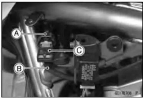
Installation
- Install:
VacuumHose
InletAirPressureSensor
Input Voltage Inspection
NOTE
○Besurethebatteryisfullycharged.
○ Theinspectionisthesameas "Input Voltage Inspection" of themainthrottlesensor.
- TurntheignitionswitchOFF.
- RemovetheECU(seeECURemoval).Donotdisconnect theECUconnectors.
- Connectadigitalvoltmeter[A]totheconnector[B]with theneedleadapterset.
SpecialTool-NeedleAdapterSet:57001-1457
- Measure the input voltage with the engine stopped, and with the connectors joined.
- TurntheignitionswitchON.

InletAirPressureSensorInputVoltage ConnectionstoECU
Meter(+)→ BLlead(terminal10) Meter(-)→ BR/BKlead(terminal28)
Standard:4.75\~5.25VDC
★ Ifthereadingiswithinthestandardrange,checkthesensoroutputvoltage.
★ Ifthereadingislessthanthestandardrange,removethe ECUandcheckthewiringbetweentheseconnectors.
★ Ifthewiringisgood, checktheECUforitsgroundand powersupply(seeECUPowerSupplyInspection).
Output Voltage Inspection
NOTE
○ Theoutputvoltagechangesaccordingtothelocalatmosphericpressure.
- Measure the output voltage at the ECU in the same way as input voltage inspection. Not the following.
InletAirPressureSensorOutputVoltage ConnectionstoECU
Meter(+)→ Y/BLlead(terminal17)
Meter(-)→ BR/BKlead(terminal14)
UsableRange: 3.74\~4.26VDCatthestandard atmosphericpressure(101.32kPa, 76cmHgabs.)
- TurntheignitionswitchOFF.
★Iftheoutputvoltageiswithintheusablerange,checkthe ECUforitsground,andpowersupply(seeECUPower SupplyInspection).
★Iftheoutputvoltageisoutoftheusablerange,remove thefueltankandcheckthewiring.Iftheoutputvoltageis 4.8V,theECUisnormal.
★Ifthewiringisgood,checkthesensorforvariousvacuum.
★Iftheoutputvoltageforvariousvacuumisnormal,check theECUforitsground,andpowersupply(seeECU PowerSupplyInspection).
- Removetheinletairpressuresensor[A]anddisconnect thevacuumhosefromthesensor.
○Donotdisconnectthesensorconnector.
- Connectanauxiliaryhose[B]totheinletairpressuresensor.
- Temporarily install the inletair pressuresensor.
○Connectacommerciallyavailabledigitalmeter[C], vacuumgauge[D], theforkoillevelgauge[E] and theharnessadapter to the inlet air pressures sensor.
SpecialTools-ForkOilLevelGauge:57001-1290
SensorHarnessAdapter:57001-1561
InletAirPressureSensorOutputVoltage
ConnectiontoAdapter
Meter(+)→ G(sensorY/BL)lead
Meter(-)→ BK(sensorBR/BK)lead


○TurntheignitionswitchON.
○Measuretheinletairpressuresensoroutputvoltagefromvariousvacuumreadings,whilepulling thehandleoftheforkoillevelgauge.
○Checktheinletairpressuresensoroutputvoltage,usingthefollowingformulaandchart.
Suppose:
Pg:VacuumPressure(gauge)toSensor
PI:LocalAtmosphericPressure(absolute)measuredbyabarometer
Pv:VacuumPressure(absolute)toSensor
Vv:SensorOutputVoltage(v)
InletAirPressureSensor(ServiceCode12)
then
$$ P v = P I - P g $$
Forexample, supposethe following data is obtained:
Pg=8cmHg(Vacuumgaugereading)
PI=70cmHg(Varometerreading)
Vv=3.2V(Digitalvoltmeterreading)
then
$$ \mathrm{Pv} = 7 0 - 8 = 6 2 \mathrm{cmHg(Abs)} $$
PlotthisPv(62cmHg)atapoint[1]onthechartanddrawaverticallinethroughthepoint. Then, you cangettheusablerange[2]ofthesensoroutputvoltage.
Usablerange=3.04\~3.49V
PlotVv(3.2V)ontheverticalline.→ Point[3].
Results: Inthechart, Vviswithintheusablerangeandthesensorisnormal.
Pv=24\~55cmHg

line
| PkPa (abs) | Vv volt (ST) | Vv volt (UR) | | ---------- | ------------ | ------------ | | 24 | 1.2 | 1.4 | | 35 | 1.4 | 1.6 | | 40 | 1.6 | 1.8 | | 50 | 1.8 | 2.0 | | 60 | 2.0 | 2.2 | | 70 | 2.2 | 2.4 | | 73 | 2.4 | 2.6 |Pv=55\~86cmHg
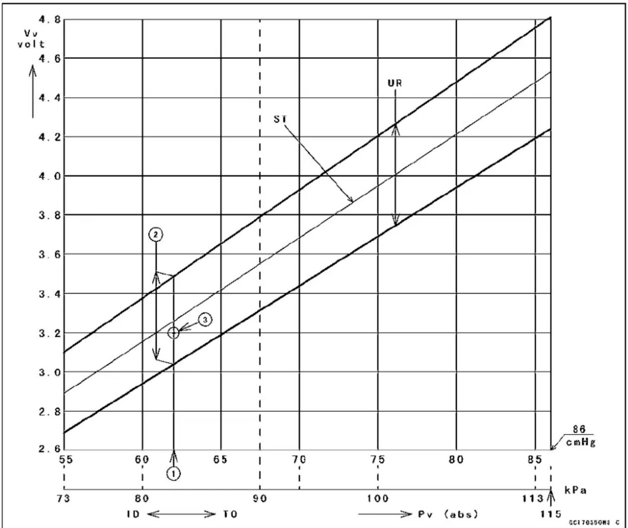
line
| Point | Pv (abs) | Vv volt | |-------|----------|---------| | 1 | 80 | 3.2 | | 2 | 80 | 3.5 | | 3 | 80 | 3.2 |Vv:InletAirPressureSensorOutputVoltage(V)(DigitalMeterReading)
Pv:ThrottleVacuumPressure(Absolute)
Ps:StandardAtmosphericPressure(Absolute)
ID:Idling
TO:ThrottleFullOpen
ST:StandardofSensorOutputVoltage(v)
UR:UsableRangeofSensorOutputVoltage(v)
InletAirPressureSensor(ServiceCode12)
InletAirPressureSensorCircuit

flowchart
graph TD
    A["①"] --> B["3"]
    A --> C["2"]
    A --> D["4"]
    B --> E["T/BL"]
    B --> F["BR/BL"]
    B --> G["BL"]
    C --> H["BR/BL"]
    C --> I["BR/BL"]
    D --> J["T/BL"]
    D --> K["BR/BL"]
    D --> L["BL"]
GC17973BH2 C
1.ECU
2. Water-proof JointE
3. Water-proof JointD
4. InletAirPressureSensor
Removal/Installation
CAUTION
Neverdropthesensor,especiallyonahardsurface. Suchashocktothesensorcandamageit.
- Removethefueltank(seeFuelTankRemoval).
- Disconnecttheconnector[A]fromtheinletairtemperaturesensor.
- Removethescrew[B].
- Pullouttheinletairtemperaturesensor[C].
- Puttheinletairtemperaturesensorintotheaircleaner housing.
- Tightenthescrewsecurely.
Output Voltage Inspection
NOTE
○ Besurethebatteryisfullycharged.
○ Theoutputvoltagechangesaccordingtotheinletair temperature.
- RemovetheECU(seeECURemoval).Donotdisconnect theECUconnectors.
- ConnectadigitalvoltmetertotheECUconnector, using needleadapterset.
SpecialTool-NeedleAdapterSet:57001-1457
- Measurethesensoroutputvoltagewiththeengine stoppedandtheconnectorjoined.
- TurntheignitionswitchON.
InletAirTemperatureSensorOutputVoltage ConnectionstoECUConnector
Meter(+)→ Ylead(terminal26)
Meter(-)→ BR/BKlead(terminal28)
Standard: about2.25\~2.50Vatinletairtemperature 20°C(68°F)
- TurntheignitionswitchOFF.
★Iftheoutputvoltageisoutofthestandard,removethe fueltankandcheckthewiring.Andiftheoutputvoltage is4.8V,theECUisnormal.
★Iftheoutputvoltageiswithinthestandard,checktheECU foritsground,andpowersupply(seeECUPowerSupply Inspection).
★Ifthewiringisgood,checkthesensorresistance. - Removetheneedleadapterset, and applysilicone sealanttothesealsoftheconnectorforwaterproofing.
SiliconeSealant(KawasakiBond:56019-120)-Seals of ECUConnectors


InletAirTemperatureSensor(ServiceCode13)
SensorResistanceInspection
- Removetheinletairtemperaturesensor.
- Suspendthesensor[A]inacontainerofmachineoilso thattheheat-sensitiveportionissubmerged.
- Suspendathermometer[B]withtheheat-sensitiveportion[C]locatedinalmostthesamedepthwiththesensor.
NOTE
○ Thesensorandthermometermustnottouchthecontainersideorbottom.
- Placethecontaineroverasourceofheatandgradually raisethetemperatureoftheoilwhilestirringtheoilgently foreventemperature.
- Usingadigitalmeter,measuretheinternalresistance ofthesensoracrosstheterminalsatthetemperatures showninthetable.
InletAirTemperatureSensorResistance
Standard:
5.4 \~ 6.6 kΩ at 0°C (68°F)
0.29 \~ 0.39 kΩ at 80°C (176°F)
★ Ifthemeasurementisoutoftherange, replacethesensor.
★ Ifthemeasurementiswithinthespecified,replace the ECU.

InletAirTemperatureSensorCircuit

GC17974BW2 C
1.ECU
2. InletAirTemperatureSensor
3. Water-proof JointE
WaterTemperatureSensorRemoval/Installation
CAUTION
Neverdropthesensor,especiallyonahardsurface. Suchashocktothesensorcandamageit.
- Drainthecoolant(seeCoolantChangeinthePeriodic Maintenancechapter).
- Disconnectthesensorconnector[A], and unscrew the watertemperaturesensor[B].
Torque-WaterTemperatureSensor:12N·m(1.2kgf·m,106 in·lb)
- ApplygreasetonewO-ringonthewatertemperaturesensor.
- Filltheenginewithcoolantandbleedtheairfromthecoolingsystem(seeCoolantChangeinthePeriodicMaintenancechapter).
WaterTemperatureSensorOutputVoltageInspection
NOTE
○ Besurethebatteryisfullycharged.
- RemovetheECU(seeECURemoval).Donotdisconnect theconnectors.
- Connectadigitalvoltmeter[A]totheECUconnector[B] withtheneedleadapterset.
SpecialTool-NeedleAdapterSet:57001-1457
- Measurethesensoroutputvoltagewiththeengine stoppedandtheconnectorjoined.
- TurntheignitionswitchON.
WaterTemperatureSensorOutputVoltage ConnectionstoECU
Meter(+)→ Olead(terminal20)
Meter(-)→ BR/BKlead(terminal28)
Standard:about2.80\~ 2.97Vat20°C(68°F)
NOTE
○ Theoutputvoltagechangesaccordingtothecoolant temperatureintheengine.
- TurntheignitionswitchOFF.
★Iftheoutputvoltageiswithinthestandard,checktheECU foritsground,andpowersupply(seeECUPowerSupply Inspection).
★Iftheoutputvoltageisoutofthestandard,checkthe wiring.Andiftheoutputvoltageis4.8V,theECUisnormal.
★Ifthewiringisgood, checkthewatertemperaturesensor resistance. - Removetheneedleadapterset, andapplysilicone sealanttothesealsoftheconnectorforwaterproofing.
SiliconeSealant(KawasakiBond:56019-120)-Seals of ECUConnectors

natural_image
Close-up of a mechanical assembly with labeled parts A and B, showing hoses and components (no readable text or symbols beyond labels)
WaterTemperatureSensor(ServiceCode14)
WaterTemperatureSensorCircuit

GC17975BH2 C
1.ECU
2. WaterTemperatureSensor
3. Water-proof JointE
4.MeterUnit
SensorResistanceInspection
- Removethewatertemperaturesensor(seeWaterTemperatureSensorRemoval/Installation).
- RefertoWaterTemperatureSensorInspectioninthe ElectricalSystemchapter.
CrankshaftSensor(ServiceCode21)
StarttheengineandswitchthediagnosismodetoDealer 1modetoknowalltheproblemthattheDFIsystemhasat thetimeofself-diagnosis. Iftheenginecannotbestarted, theself-diagnosisissystemdoesnotdetectdynamicconditionofthecrankshaftsensor. Inthiscase, turnofftheignitionswitchandturnitonagaintoentertheDealer2mode. Inthismode, thesystemtellsallthetroubleswhichtheDFIsystemhadinbothstaticanddynamicconditions.
CrankshaftSensorRemoval/Installation
- SeethelIgnitionSystemsectionintheElectricalSystem chapter.
CrankshaftSensorInspection
○Thecrankshaftsensorhasnopowersource, and when theenginestops, thecrankshaftsensorgeneratesnosignals.
- Cranktheengineandmeasurethepeakvoltageofthecrankshaftsensor(seeCrankshaftSensorInspectionintheElectricalSystem)inordertocheckthesensor.
- Checkthewiringforcontinuity, using the following diagram.
CrankshaftSensorCircuit

GC17976BH2 C
- ECU
2.CrankshaftSensor
SpeedSensor(ServiceCode24,25)
SpeedSensorRemoval/Installation
- SeetheSwitchesandSensorssectionintheElectrical Systemchapter.
SpeedSensorInspection
- SeeSpeedSensorInspectionsectionintheElectrical Systemchapter.
SpeedSensorInputVoltageInspection
NOTE
○Besurethebatteryisfullycharged.
- TurntheignitionswitchOFF.
- Disconnectthespeedsensorconnectorandconnectthe harnessadapter[A]betweentheharnessconnectorand speedsensorconnector.
- Connectadigitalmetertotheharnessadapterleads.
SpecialTool-ThrottleSensorSettingAdapter#1:57001-1400
- Measurethesensorinputvoltagewiththeengine stopped, and with the connector joined.
- TurntheignitionswitchON.
SpeedSensorInputVoltage
ConnectiontoAdapter
Meter(+)→ BL(sensorP)lead[C] Meter(-)→ BK(sensorBK/Y)lead[D]
Standard: About9\~ 11VDCatlgnitionSwitchON
★ Ifthereadingisoutoftherange, checkthewiring(see wiringdiagraminthissection), andmeter(seeElectronic CombinationMeterUnitInspectionintheElectricalSystemchapter).
★ If thereading is good, check the output voltage.
- TurntheignitionswitchOFF.
SpeedSensorOutputVoltageInspection
- Beforethisinspection, inspecttheinputvoltage(see SpeedSensorInputVoltageInspection).
NOTE
○Besurethebatteryisfullycharged.
- TurntheignitionswitchOFF.
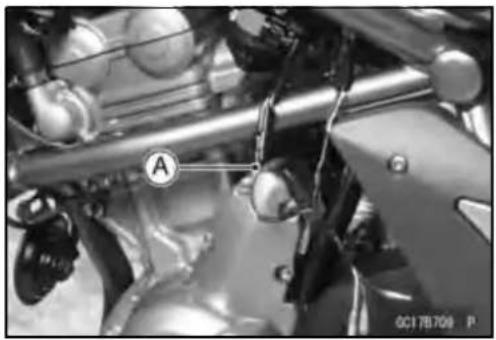
natural_image
Close-up mechanical assembly with labeled component A (no readable text or symbols beyond label)
3-56FUELSYSTEM(DFI)
SpeedSensor(ServiceCode24,25)
- Disconnectthespeedsensorconnectorandconnectthe harnessadapter[A]betweentheharnessconnectorand speedsensorconnector.
- Connectadigitalmetertotheharnessadapterleads.
SpecialTool-ThrottleSensorSettingAdapter#1:57001 -1400 - Measurethesensoroutputvoltagewiththeengine stopped, and with the connector joined.
- TurntheignitionswitchON.
SpeedSensorOutputVoltageatSensor ConnectionstoAdapter
Meter(+)→ Y/W(sensorLG/R)lead[C]
Meter(-)→ BK(sensorBK/Y)lead[D]
Standard: About0.05\~ 0.07VDC
NOTE
○ Ifyourotatetheenginesprocket, the output voltage will be increased.
★Ifthereadingisoutoftherange,checkthespeedsensor operation(seeSpeedSensorInspectionintheElectrical Systemchapter)andthewiringtoECU(seewiringdiagraminthissection).
★Ifthereading,speedsensoroperationandwiringare good,checktheECUforitsground,andpowersupply (seeECUPowerSupplyInspection).

natural_image
Close-up mechanical assembly showing gears and shafts with no visible text or symbols
SpeedSensorCircuit

flowchart
graph TD
    A["①"] --> B["②"]
    B --> C["③"]
    C --> D["④"]
    D --> E["⑤"]
    E --> F["⑥"]
    C --> G["①"]
    G --> H["②"]
    H --> I["③"]
    I --> J["④"]
    style A fill:#f9f,stroke:#333
    style B fill:#ccf,stroke:#333
    style C fill:#cfc,stroke:#333
    style D fill:#fcc,stroke:#333
    style E fill:#ffc,stroke:#333
    style F fill:#cff,stroke:#333
    style G fill:#ffc,stroke:#333
    style H fill:#cfc,stroke:#333
    style I fill:#cfc,stroke:#333
GC17977BW2 C
1.ECU
2.SpeedSensor
3.MeterUnit
4. Water-proof JointB
5.FrameGround
6.JointConnector
Vehicle-downSensor(ServiceCode31)
Vehicle-downSensorRemoval
CAUTION
Neverdropthedown-sensor,especiallyonahard surface.Suchashocktothesensorcandamageit.
- Remove:
Bolts[A]
ConnectionandVehicle-downSensor[B]
Vehicle-downSensorInstallation
- TheUPmark[A]ofthesensorshouldfaceupward.
WARNING
Incorrect installation of the vehicle-downsensor could cause sudden loss of engine power. The rider could lose balanced during certain ridings situations like leaning over in aturn with the potential for an accident resulting in injury or death. Ensure that the downsensor is held in place by the sensor brackets.
Vehicle-down Sensor Inspection
NOTE
○Besurethebatteryisfullycharged.
- Connectadigitalvoltmeter[C]totheconnector[B]ofthe vehicle-downsensor[A]withtheneedleadapterset[D].
Vehicle-downSensorPowerSourceVoltage ConnectionstoSensor
Meter(+)→ BLlead[D]
Meter(-)→ BR/BKlead[E]
- TurntheignitionswitchON, and measure the power source voltage with the connector joined.
Vehicle-downSensorInputVoltage Standard:4.75\~5.25VDC
- TurntheignitionswitchOFF.
★ Ifthereadingofinputvoltageislessthanthestandard, checktheECUforitsground,powersupplyandwiring shorted.
★ Ifthepowersourceisnormal, checktheoutputvoltage.

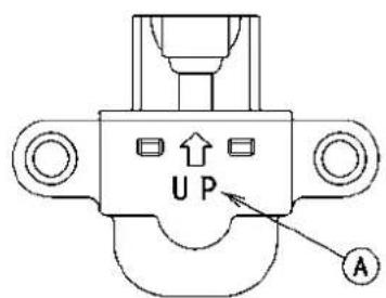
0C17004CS1 C


0C17312BS2 C
Vehicle-downSensor(ServiceCode31)
- Removethesensor.
- Connectadigitalvoltmeter[A]totheconnectorwithneedleadapterset[B].
SpecialTool-NeedleAdapterSet:57001-1457
Vehicle-downSensorOutputVoltage ConnectionstoSensor
Meter(+)→ Y/Glead[E]
Meter(-)→ BR/BKlead[F]
- Holdthesensorvertically.
- TurntheignitionswitchON, and measure the output voltage with the connector joined.
○Tilt the sensor 60 \~ 70° or more [C] right or left, then hold the sensor almost vertical with the arrow mark pointed up [D], and measure the output voltage.
OutputVoltageatSensor
Standard:withsensortilted60\~70°ormoreright orleft:0.65\~1.35V
withsensorarrowmarkpointedup: 3.55\~4.45V

NOTE
○ Ifyouneedtotestagain,turntheignitionswitchOFF, andthenON.
- TurntheignitionswitchOFF.
- Removetheneedleadapterset, and applysilicone sealanttothesealsoftheconnectorforwaterproofing.
SiliconeSealant(KawasakiBond:56019-120)-Seals of Vehicle-down Sensor Connector
★Iftheoutputvoltageisnormal,thewiringissuspect. Checkthewiring.
★Ifthewiringisgood,checktheECUforitsgroundand powersupply(seeECUPowerSupplyInspection).
★ If the output voltage is out of the specified, replace the vehicle-downsensor.
Vehicle-downSensor(ServiceCode31)
Vehicle-downSensorCircuit

GC17978BH2 C
1.ECU
2. Water-proofJointE
3. Vehicle-downSensor
4. Water-proof JointD
SubthrottleSensorRemoval/Adjustment
CAUTION
Donotremoveoradjustthesubthrottlesensor[A] sinceithasbeenadjustedandsetwithprecisionat thefactory.
Neverdropthesensor,especiallyonahardsurface.
Suchashocktothesensorcandamageit.
SubthrottleSensorInputVoltageInspection
NOTE
○ Besurethebatteryisfullycharged.
- Removethefueltank(seeFuelTankRemoval).
- TurntheignitionswitchOFF.
- Disconnect the subthrottlesensorconnector and connect the harness adapter[A] between these connectors.
- Connectadigitalmetertotheharnessadapterlead.
SpecialTool-ThrottleSensorHarnessAdapter:57001
-1400
- Measurethesensorinputvoltagewiththeenginestopped andwiththeconnectorjoined.
- TurntheignitionswitchON.
SubthrottleSensorInputVoltage
ConnectionstoAdapter
Meter(+)→ BL(sensorBL)lead
Meter(-)→ BK(sensorBR/BK)lead
Standard:4.75\~5.25VDC
- TurntheignitionswitchOFF.
★Iftheinputvoltageisnormal,checkthesensoroutput voltage.
★ If the input voltage is less than the standard, removes the ECU and check the wiring between these connectors.
○DisconnecttheECUandsensorconnectors.
WiringConnection
ECUConnector[A]←→
SubthrottleSensorConnector[B]
BLlead(terminal10)
natural_image
Close-up of a mechanical component with visible wiring and a labeled section (A), no readable text or symbols present.
natural_image
Close-up of an automotive engine bay with hoses and components (no visible text or symbols)
SubthrottleSensor(ServiceCode32)
SubthrottleSensorOutputVoltageInspection
- Removethefueltank(seeFuelTankRemoval).
- Measure the output voltage at the subthrottlesensor in the same way as input voltage inspection. Not the following.
- Disconnectthesubthrottlesensorconnectorand(black)connecttheharnessadapter[A]betweentheseconnectors.
SpecialTool-ThrottleSensorHarnessAdapter:57001-1400
- Measure the output voltage of the sensor with the engine stopped, and with the connector joined.
- TurntheignitionswitchON.
- Measure the output voltage when the subthrottle valve is fully opened or completely closed by hand.
SubthrottleSensorOutputVoltage ConnectionstoAdapter
Meter(+)→ Y(sensorBL/W)lead Meter(-)→ BK(sensorBR/BK)lead
Standard:
0.4\~ 0.6VDC(atidlethrottleopening) 3.625\~ 3.775VDC(atfullthrottleopening)
★ If the output voltage is out of the standard, inspect the subthrottles sensor resistance.
★ Iftheoutputvoltageisnormal, checkthewiringforcontinuity.
WiringConnection
ECUConnector[A]←→ SubthrottleSensorConnector[B] BL/Wlead(terminal7) BR/BKlead(terminal28)
★ Ifthewiringisgood, checktheECUforitsgroundand powersupply(seeECUPowerSupplyInspection).

natural_image
Close-up of a mechanical assembly with hoses and components, no visible text or symbols
3-62FUELSYSTEM(DFI)
SubthrottleSensor(ServiceCode32)
SubthrottleSensorResistanceInspection
- TurntheignitionswitchOFF.
- Disconnectthesubthrottlesensorconnector.
- Connectadigitalmeter[A]tothesubthrottlesensorconnector[B].
- Measurethesubthrottlesensorresistance.
ThrottleSensorResistance
Connections:BLlead[C]←→ BKlead[D]
Standard:4\~6 k Ω

★Ifthereadingisoutoftherange,replacethethrottlebody assy.
★Ifthereadingiswithintherange,buttheproblemstill exists,replaceECU(seeECUsection).
SubthrottleSensorCircuit

GC17979BH2 C
- ECU
- Water-proof JointE
- Water-proof JointD
4.SubthrottleSensor
OxygenSensor-notactivated(ServiceCode33)-EuropeModel
OxygenSensorRemoval/Installation
- RefertoSwitchesandSensorssectionintheElectrical Systemchapter.
OxygenSensorInspection
- Warmuptheenginethoroughlyuntiltheradiatorfan starts.
- TurntheignitionswitchOFF.
- Remove: LeftCenterFairing(seeCenterFairingRemovalinthe Framechapter) SprocketCover(seeEngineSprocketRemovalinthe FinalDrivechapter)
- Connectadigitalvoltmeter[A]totheoxygenensorconnectorB,usingtheneedleadapter set[C].
SpecialTool-NeedleAdapterSet:57001-1457
OxygenSensorOutputVoltage ConnectionstoOxygenSensorConnector
Meter(+)→ BL/YIlead
Meter(-)→ BR/BKlead
- Removetheairswitchingvalvehosesfromthefitting.
- Installthesuitableplugs[A]onthefitting[B]andshutoff thesecondaryair.


- TurntheignitionswitchON.
- Starttheengine, andletitidle.
- Measure the output voltage of the sensor with the connector joined.
OxygenSensorOutputVoltage(withPlugs)
Standard: 0.7Vormore
- Next,removetheplugsfromthefitting[A]withidling.

natural_image
Close-up of a mechanical assembly with labeled component A (no readable text or symbols beyond label)OxygenSensor-notactivated(ServiceCode33)-EuropeModel
- Measure the output voltage of the sensor with the connector joined.
OxygenSensorOutputVoltage(withoutPlugs)
Standard: 0.2Vorless
★Ifthereadingiswithinrange(withplugs:0.7Vormore,
withoutplugs:0.2Vorless),theoxygenensorisgood.
★Ifthereadingiswithoutrange,replaceoxygenensor.
OxygenSensorCircuit
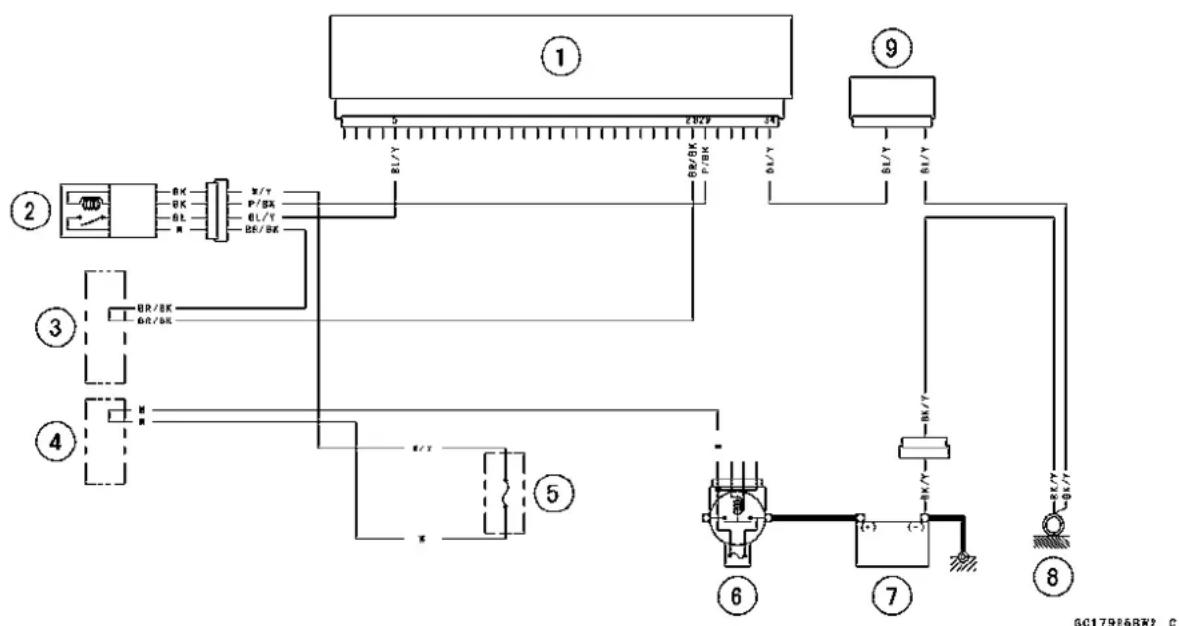
flowchart
graph TD
    A["①"] --> B["②"]
    B --> C["③"]
    C --> D["④"]
    D --> E["⑤"]
    E --> F["⑥"]
    F --> G["⑦"]
    G --> H["⑧"]
    H --> I["⑨"]

    subgraph Component 1
        J["BL/Y"] --> K["BR/BR/FBR"]
        L["BL/Y"] --> M["BR/BR"]
        N["BL/Y"] --> O["BR/BR"]
        P["X/Y"] --> Q["P/BR"]
        R["GL/Y"] --> S["BL/BR"]
        T["X/Y"] --> U["X/Y"]
    end

    subgraph Component 2
        V["OK"] --> W["OK"]
        X["OK"] --> Y["OK"]
        Z["X"] --> AA["X"]
    end

    subgraph Component 3
        AB["UR/BR"]
        AC["DR/BR"]
    end

    subgraph Component 4
        AD[" "] --> AE[" "]
    end

    subgraph Component 5
        AF["X/Y"] --> AG["X/Y"]
    end

    subgraph Component 6
        AH[" "] --> AI[" "]
        AJ["X/Y"] --> AK["X/Y"]
    end

    subgraph Component 7
        AL[" "] --> AM[" "]
        AN["X/Y"] --> AO["X/Y"]
    end

    subgraph Component 8
        AP["X/Y"] --> AQ["X/Y"]
    end

    style Component 1 fill:#f9f,stroke:#333
    style Component 2 fill:#ccf,stroke:#333
    style Component 3 fill:#cfc,stroke:#333
    style Component 4 fill:#fcc,stroke:#333
    style Component 5 fill:#cff,stroke:#333
    style Component 6 fill:#ffc,stroke:#333
    style Component 7 fill:#cfc,stroke:#333
    style Component 8 fill:#fcc,stroke:#333
- ECU
2.OxygenSensor - Water-proof JointE
- Water-proof JointD
5.OxygenSensorHeaterFuse10A
6.MainFuse30A
7.Battery
8.FrameGround
9.JointConnector
StickCoils(#1,#2:ServiceCode51,52)
StickCoil#1:IgnitionCoil(ServiceCode51)
StickCoil#2:IgnitionCoil(ServiceCode52)
StickCoilRemoval/Installation
CAUTION
Neverdropthestickcoils,especiallyonahardsurface.Suchashocktothestickcoilcandamageit.
- RefertotheIgnitionSystemsectionintheElectricalSystemchapter.
StickCoilInputVoltageInspection
NOTE
○Besurethebatteryisfullycharged.
- TurntheignitionswitchOFF.
- RemovetheECU(seeECURemoval).Donotdisconnect theECUconnector.
- Connectadigitalvoltmeter[A]asshown,withtheneedle adapterset[B].
○Measure the input voltage to each primary winding of the ignition coil with the engine stopped, and with the connectors joined. - TurntheignitionswitchON.
Stick Coil Input Voltage at ECU Connections for Stick Coil #1
Meter(+)→ BKlead(terminal43)
Meter(-)→ BK/Ylead(terminal51)
ConnectionsforStickCoil#2
Meter(+)→ BK/Glead(terminal52)
Meter(-)→ BK/Ylead(terminal51)
InputVoltageatECU
Standard: Battery Voltage(12.8Vormore)
★ If thereading is out of the standard, check the wiring (see next wiring diagram).
★ Ifthereadingisgood, theinputvoltageisnormal. Crank theengine, and check the peak voltage of the stick coils (see Stick Coil Primary Peak Voltage in the Electrical System chapter) in order to check the primary coils.

StickCoilCircuit
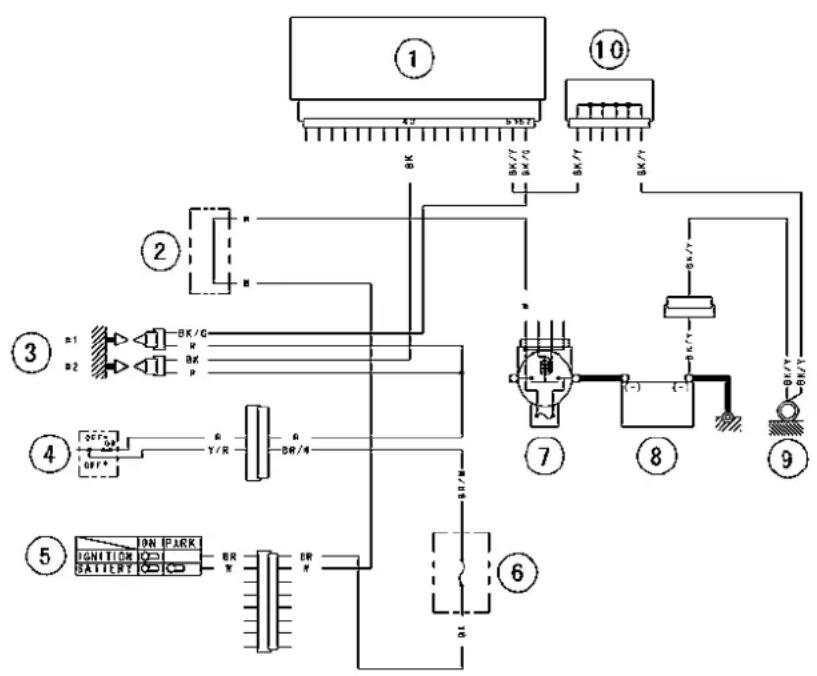
GC17980BH2 C
- ECU
- Water-proof JointC
3.StickCoils - EngineStopSwitch
- IgnitionSwitch
6.IgnitionFuse10A
7.MainFuse30A
8.Battery
9.FrameGround
10.JointConnector
RadiatorFanRelay(ServiceCode56)
RadiatorFanRelayRemoval/Installation
- Radiatorfanrelayisbultintherelaybox.
- Removetherelaybox(seeRelayBoxRemovalinthe ElectricalSystemchapter).
RadiatorFanRelayInspection
- SeeRelayCircuitInspectionintheElectricalSystem chapter.
- RemovetherelayboxandECU(seeECUREmoval).Do not disconnecttherelayboxandECUconnectors.Check the wiring for continuity, using the following diagram.
★Ifwiringandradiatorfanrelayaregood,checktheECU foritsground,andpowersupply(seeECUPowerSupply Inspection).Ifthegroundandpowersupplyaregood, replacetheECU.
RadiatorFanRelayCircuit

1.ECU
2. Water-proof JointC
3. Water-proof JointB
4. RadiatorFanFuse15A
5.RelayBox
6.RadiatorFanRelay
7.MainFuse30A
8.Battery
9.FrameGround
10.JointConnector
Subthrottle ValveActuatorRemoval
CAUTION
Donotremovethesubthrottlevalveactuator[A] sinceithasbeenadjustedandsetwithprecision atthefactory.
Neverdroptheactuator,especiallyonahardsurface.Suchashocktotheactuatorcandamageit.

natural_image
Close-up of a mechanical assembly with labeled component A (no readable text or symbols beyond label)Subthrottle Valve Actuator Audible Inspection
NOTE
○ Besurethebatteryisfullycharged.
- TurntheignitionswitchONandensurethattheactuator valvesopenandclose(makelightsounds)severaltimes withinseconds, and then close at the idle throttle opening position.
- TurntheignitionswitchOFF.
★Iftheactuatordoesnotworkasdescribedabove,dothe visualinspection.
Subthrottle Valve Actuator Visual Inspection
- Removethethrottlebodyassy(seeThrottleBodyAssyRemoval).
- TurntheignitionswitchON.
- Checktoseethatallthesubthrottlevalves[A]openand closesmoothly.
★If the subthrottle valves donot operate, check the actuator internal resistance (see Subthrottle Valve Actuator Resistance Inspection).
Subthrottle Valve Actuator Resistance Inspection
- TurntheignitionswitchOFF.
- Removethethrottlebodyassy(see ThrottleBodyAssy Removal).
-
Disconnectthesubthrottlevalveactuatorconnector[A].
-
Connectadigitalmetertothesubthrottlevalveactuator connector[A].
- Measure the subthrottle valve actuator resistance.
SubthrottleValveActuatorResistance
Connections:BKlead[1]←→ Plead[2]
Glead[3]←→ W/BLlead[4]
Standard: About5.5\~7.5kΩ
SpecialTool-HandTester:57001-1394
★Ifthereadingisoutoftherange,replacetheactuator alongwiththethrottlebodyassy.
★Ifthereadingiswithintherange,checktheinputvoltage (seeSubthrottleValveActuatorInputVoltageInspection).

natural_image
Close-up of a mechanical component with two circular cavities and a labeled section A, being handled by a hand (no readable text or symbols)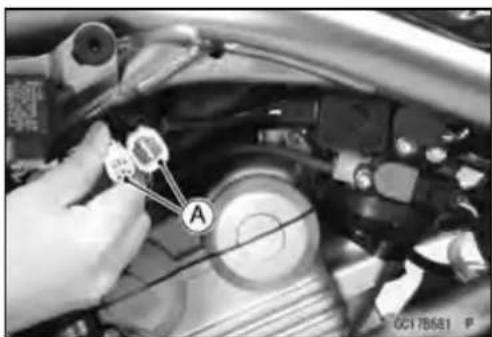

0C171598S1 C
SubthrottleValveActuator(ServiceCode62)
Subthrottle Valve Actuator Input Voltage Inspection
NOTE
○Besurethebatteryisfullycharged.
- TurntheignitionswitchOFF.
- Connectthepeakvoltageadapter[A]andadigitalmeter[B]totheconnector[C],usingtheneedleadapterset[D].
SpecialTools-PeakVoltageAdapter:57001-1415
Type:KEK-54-9-B
Brand:KOWASEIKI
NeedleAdapterSet:57001-1457
SubthrottleValveActuatorInputVoltage ConnectionstoHarnessConnector
(I)Meter(+)→ B K / B L I e a d [1]
Meter(-)→ Plead[2]
(II)Meter (+) W/BLlead[3]
Meter(-)→ G/Ylead[4]
- Measure the actuator input voltage with the engine stopped, and with the connector joined.
- TurntheignitionswitchON.
InputVoltageatActuator
Standard: about8.5\~10.5VDC
★If the reading is within the standard but the actuator doesn't operate, replace it.
★ If thereading is out of the range, check the wiring to ECU (seewiring diagram in this section).
★ If the wiring is good, check the ECU for its ground and powersupply (see ECUPowerSupplyInspection).
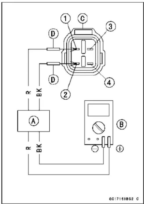
SubthrottleValveActuatorCircuit

GC17981BH2
1.ECU
2.SubthrottleValveActuator
AirSwitching ValveRemoval/Installation
- RefertoCleanAirSystemsectionintheEngineTopEnd chapter.
AirSwitchingValveInspection
- RefertoAirSwitchingValvesectionintheElectricalSystemchapter.
- Removethefueltankandcheckthewiringcontinuity,usingthefollowingdiagram.
AirSwitchValveCircuit

flowchart
graph TD
    A["Component 1"] -->|R/RL| B["Relays"]
    C["Component 2"] -->|R/R| D["Switch"]
    E["Component 3"] -->|R/R| F["Switch"]
    G["Component 4"] --> H["Reactor with Battery"]
    I["Component 5"] --> J["Switch"]
    K["Component 6"] --> L["Switch"]
    M["Component 7"] --> N["Switch"]
    O["Component 8"] --> P["Switch"]
    Q["Component 9"] --> R["Switch"]
    S["Component 10"] --> T["Switch"]
    U["Component 11"] --> V["Switch"]
    W["Component 12"] --> X["Switch"]
    Y["Ground"] --> Z["Ground"]
- ECU
- AirSwitchingValve
3.Water-proofJointC - IgnitionSwitch
- Water-proof JointA
6.ECUFuse15A
7.ECUMainRelay
8.RelayBox
9.MainFuse30A
10.Battery
11.FrameGround
12.JointConnector
OxygenSensorHeater(ServiceCode67)-EuropeModel
OxygenSensorHeaterRemoval/Installation
Theoxygen sensor heater is built in the oxygen sensor. So, the heater itself cannot be removed. Removethe oxygen sensor (see Oxygen Sensor Removal in the Electrical System chapter).
OxygenSensorHeaterInspection
- Removetheenginesprocketcover(seeEngineSprocketRemovalintheFinalDrivechapter).
- Disconnecttheoxygen sensorleadconnector[A].
- Setthehandtester[A]tothe×1Ω rangeandconnectit totheterminalsintheoxygenensorleadconnector[B]. Black[C] Black[D]
SpecialTool-HandTester:57001-1394
OxygenSensorResistance
Standard: 11.7 \~ 14.5 Ω at 20°C (68°F)
★ Ifthetesterreadingisnotasspecified, replacetheoxygen sensorwithanewone.
★ If the tester reading is specified, check the powers source voltage inspection.
NOTE
○Besurethebatteryisfullycharged.
- Connectadigitalvoltmeter[A]totheoxygenensorconnector[B],usingtheneedleadapter[C].
SpecialTool-NeedleAdapterSet:57001-1457
- Measure the powersource voltage with the engine stopped, and with the oxygensensor connector joined.
OxygenSensorPowerSourceVoltage
ConnectionstoOxygenSensorConnector
Tester(+)→ W/Ylead[D]
Tester (-) Battery (-) Terminal [E]
Standard: BatteryVoltage
OxygenSensor[F]
★ If thereading is incorrect, check the following. Battery
MainFuse30A
OxygenSensorHeaterFuse10A
★ Ifthereadingisgood, thepowersourcevoltageisnormal, InspecttheRed/Blackleadbetweentheoxygenensor connectorandtheECUforcontinuity, usingthefollowing diagram.
★ Ifthewiringisgood, inspecttheECUforitsground, and powersupply(seeECUPowerSupplyInspection). If the groundandpowersupplyaregood, replacetheECU.

natural_image
Close-up of a hand using a tool to adjust mechanical components, no visible text or symbols

OxygenSensorCircuit

flowchart
graph TD
    A["①"] -->|5 V/7| B["②"]
    A -->|28V/8K P/8K BL/8K BL/7| C["③"]
    A -->|6V/7| D["④"]
    A -->|BL/7| E["⑤"]
    A -->|BL/7| F["⑥"]
    A -->|BL/7| G["⑦"]
    A -->|BL/7| H["⑧"]
    A -->|BL/7| I["⑨"]
    style A fill:#f9f,stroke:#333
    style B fill:#ccf,stroke:#333
    style C fill:#cfc,stroke:#333
    style D fill:#fcc,stroke:#333
    style E fill:#cff,stroke:#333
    style F fill:#ffc,stroke:#333
    style G fill:#fcc,stroke:#333
    style H fill:#ffc,stroke:#333
    style I fill:#fcc,stroke:#333
1.ECU
2.OxygenSensor
3. Water-proof JointE
4. Water-proof JointD
5.OxygenSensorHeaterFuse10A
6.MainFuse30A
7.Battery
8.FrameGround
9.JointConnector
OxygenSensor-IncorrectOutputVoltage(ServiceCode94)-EuropeModel
OxygenSensorRemoval/Installation
- RefertoOxygenSensorRemoval/InstallationintheElectricalSystemchapter.
OxygenSensorInspection
- Warmuptheenginethoroughlyuntiltheradiatorfan starts.
- TurntheignitionswitchOFF.
- Remove: LeftCenterFairing(seeCenterFairingRemovalinthe Framechapter) SprocketCover(seeEngineSprocketRemovalinthe FinalDrivechapter)
- Connectadigitalvoltmeter[A]totheoxygenensorconnectorB,usingtheneedleadapter set[C].
SpecialTool-NeedleAdapterSet:57001-1457
OxygenSensorOutputVoltage ConnectionstoOxygenSensorConnector
Meter(+)→ BL/YIlead
Meter(-)→ BR/BKlead
- Removetheairswitchingvalvehosesfromthefitting.
- Installthesuitableplugs[A]onthefitting[B]andshutoff thesecondaryair.
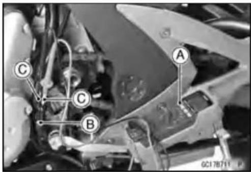

- TurntheignitionswitchON.
- Starttheengine, and let it idle.
- Measure the output voltage of the sensor with the connector joined.
OxygenSensorOutputVoltage(withPlugs)
Standard: 0.7Vormore
- Next,removetheplugsfromthefitting[A]withidling.
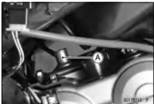
natural_image
Close-up of a mechanical assembly with labeled component A (no readable text or symbols beyond label)OxygenSensor-IncorrectOutputVoltage(ServiceCode94)-EuropeModel
- Measure the output voltage of the sensor with the connector joined.
OxygenSensorOutputVoltage(withoutPlugs)
Standard: 0.2Vorless
★Ifthereadingiswithinrange(withplugs:0.7Vormore, withoutplugs:0.2Vorless),theoxygenensorisgood.
★Ifthereadingiswithoutrange,inspecttheengineandfuel supplysystem.
★Iftheengineandfuelsupplysystemgood,replacethe oxygensensor.
OxygenSensorCircuit
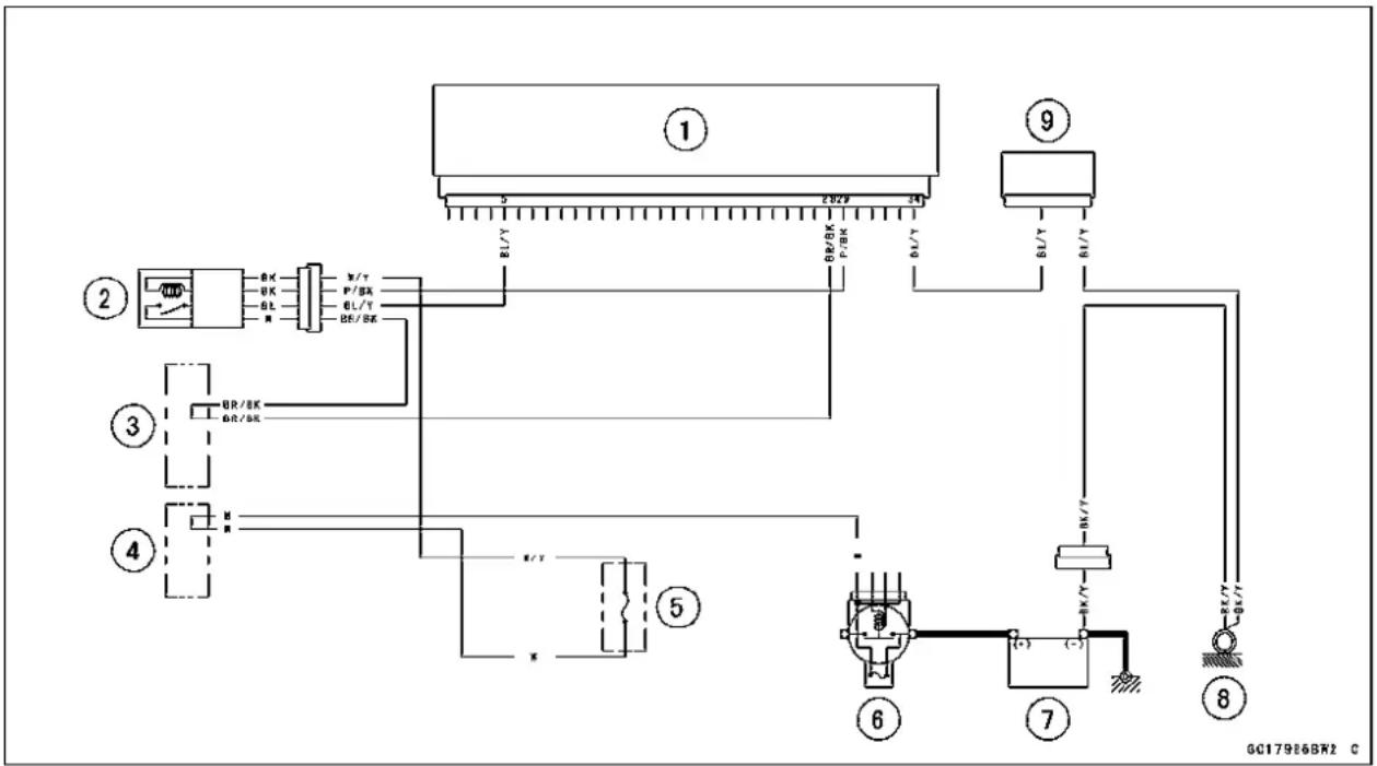
flowchart
graph TD
    A["①"] -->|BL/Y| B["②"]
    A -->|P/BR| C["③"]
    A -->|BL/T| D["④"]
    A -->|BL/T| E["⑤"]
    A -->|BL/T| F["⑥"]
    A -->|BL/T| G["⑦"]
    A -->|BL/T| H["⑧"]
    A -->|BL/T| I["⑨"]
    style A fill:#f9f,stroke:#333
    style B fill:#ccf,stroke:#333
    style C fill:#cfc,stroke:#333
    style D fill:#fcc,stroke:#333
    style E fill:#cff,stroke:#333
    style F fill:#ffc,stroke:#333
    style G fill:#fcc,stroke:#333
    style H fill:#ffc,stroke:#333
    style I fill:#fcc,stroke:#333
1.ECU
2.OxygenSensor
3. Water-proof JointE
4. Water-proof JointD
5.OxygenSensorHeaterFuse10A
6.MainFuse30A
7.Battery
8.FrameGround
9.JointConnector
FllIndicatorLight(LED)
InspectionFlowChart

flowchart
graph TD
    A["Turn the ignition SW ON."] --> B["Does the light (LED) goes on?"]
    B -->|Yes (goes on)| C["Does the light (LED) go off after 1~2 seconds?"]
    B -->|No (Flashes once then goes off or unfit)| D["Check the light (LED) and the wiring."]
    D -->|Good| E["DFI and ignition systems are considered to be normal."]
    E --> F["DFI and ignition systems are abnormal."]
    F --> G["Turn the ignition SW OFF."]
    G --> H["Turn the ignition SW OFF."]
    H --> I["Run the engine with idling."]
    I --> J["Does the light (LED) go off after 10~20 seconds?"]
    J --> K["Turn the ignition SW OFF."]
    K --> L["Ask the rider if the problem occurs again."]
    L -->|No| M["DFI and ignition systems are normal."]
    L -->|Yes (occurs)| N["Replace the ECU."]
    N --> A
    A --> O["Repair or replace the meter or wiring"]
    O --> P["NG"]
GC17852B F
FllIndicatorLight(LED)
FllndicatorLight(LED)Inspection
- Removethemeterunit(seeMeterUnitRemovalinthe ElectricalSystemchapter).
- Usingtwoauxiliaryleads, supplybatterypowertotheFI indicatorlight(LED)[A]. 12VBattery[B]
FllIndicatorLight(LED)Check
Connector:MeterConnectorC
Connection: W/BKLeadTerminal[1] of the Meter → Battery(+)Terminal
BR/RLeadTerminal[16]oftheMeter → Battery(−)Terminal
Criterion: Thelight(LED) shouldlight.
★Ifthelight(LED)doesnotgoon,replacemetheterunit.
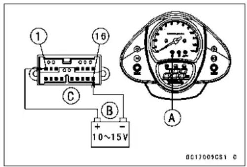
FllIndicatorLight(LED)Circuit
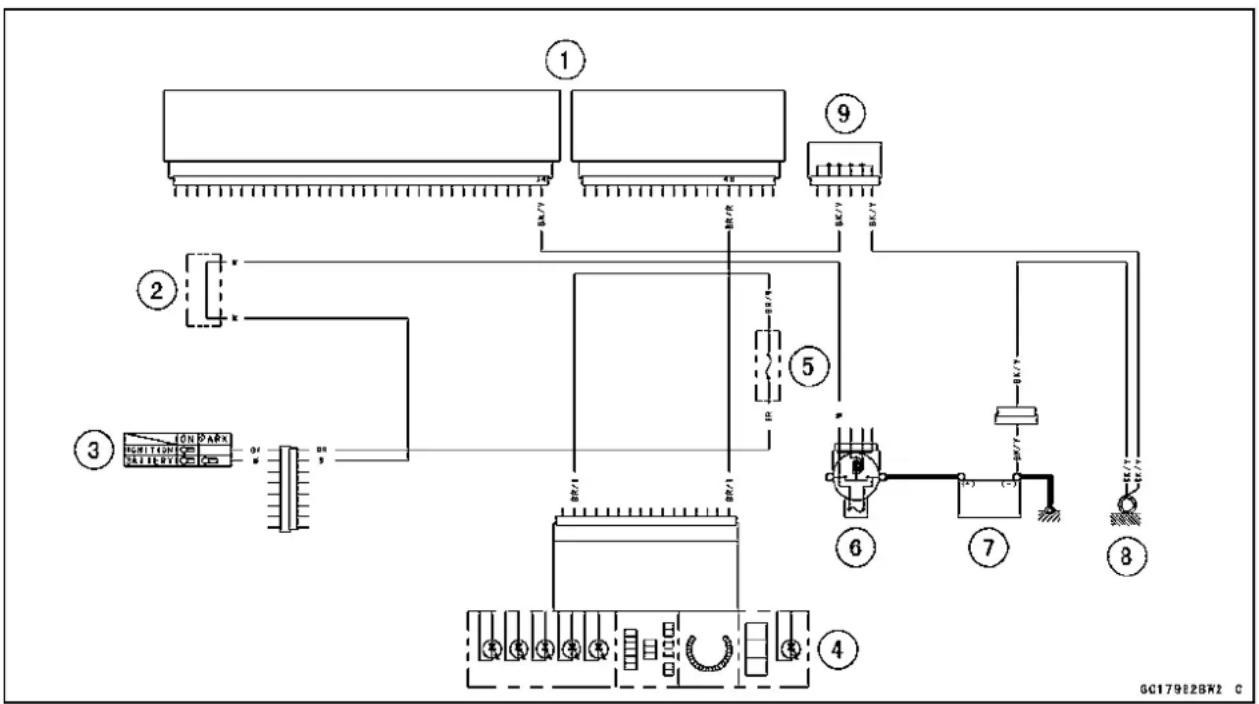
flowchart
graph TD
    A["1"] --> B["2"]
    B --> C["3"]
    C --> D["4"]
    D --> E["5"]
    E --> F["6"]
    F --> G["7"]
    G --> H["8"]
    H --> I["9"]
    I --> J["10"]
    style A fill:#f9f,stroke:#333
    style B fill:#ccf,stroke:#333
    style C fill:#cfc,stroke:#333
    style D fill:#fcc,stroke:#333
    style E fill:#cff,stroke:#333
    style F fill:#ffc,stroke:#333
    style G fill:#cfc,stroke:#333
    style H fill:#fcc,stroke:#333
    style I fill:#ffc,stroke:#333
1.ECU
2. Water-proof JointC
3. IgnitionSwitch
4.MeterUnit
5. IgnitionFuse10A
6.MainFuse30A
7.Battery
8.FrameGround
9.JointConnector
ECU
CAUTION
NeverdroptheECU,especiallyonahardsurface.
SuchashocktotheECUcandamageit.
ECURemoval
- Remove:
Seat(seeSeatRemovalintheFramechapter) GrabRailsA CenterSeatCoverB SeatCoversC RearFenderRearBolts[D]
- Pulldowntherearfenderrear[A].


natural_image
Close-up of a motorcycle's front wheel and side gear assembly (no visible text or symbols)- RemovetheECUbracketbolts[A].
• TaketheECU[B]outalongwiththeharness. - DisconnecttheECUleadconnectors.
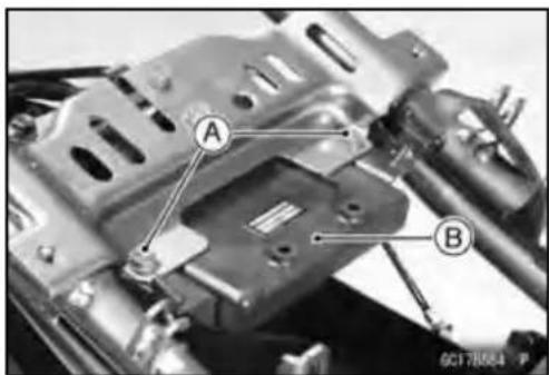
ECUInstallation
- Fit[A]thebracketontheECUasshown.

ECU
ECUPowerSupplyInspection
- Visuallyinspecttheterminals[A]oftheECUconnectors.
★Iftheconnectoriscloggedwithmudordust,blowitoff withcompressedair.
★Replacethemainharnessiftheterminalsofthemain harnessconnectorsarecracked,bent,orotherwisedamaged.
★ReplacetheECUiftheterminalsoftheECUconnectors arecracked,bent,orotherwisedamaged.
- WiththeECUconnectors[A]connected,checkthefollowinggroundleadforcontinuitywiththeignitionswitch OFF,usingatesterandneedleadapterset.
Battery[B] Tester[C]
SpecialTool-NeedleAdapterSet:57001-1457
ECUGroundingInspection
34,50,or51(BK/Y) Terminal
Battery(-)Terminal:0Ω
EngineGround
←→ Battery(−)Terminal:0Ω
★Ifnocontinuity,checktheconnector,theengineground lead,ormainharness,andrepairorreplacethemifnecessary.
- ChecktheECUpowersourcevoltagewithadigitalmeter [A].
○Positiontheterminalinaccordancewithterminalnumbers ofECUconnectors[B]inthischapterfigure. Battery[C]
ECUPowerSourceInspection
MeterConnections:
BetweenTerminal16(BR/W)andBattery(−)Terminal
BetweenTerminal17(W/BK)andBattery(−)Terminal
IgnitionSwitchOFF:
Terminal16(BR/W):0V
Terminal17(W/BK):BatteryVoltage(12.6Vormore)
IgnitionSwitchON:
Both:BatteryVoltage(12.6Vormore)
★Ifthemeterdoesnotreadasspecified,checkthefollowing:
MainFuse30A(seeFusesectionintheElectricalSystemchapter)
ECUFuse15A(seeFuseInspectionintheElectrical Systemchapter)
ECUMainRelay(seeRelayCircuitInspectioninthe ElectricalSystemchapter)
PowerSourceWiring(seewiringdiagrambelow)
★Iftheinspectionchecksgood,theECUisdamaged.ReplaceetheECU.TheECUitselfcannotbecheckedorserviced.

natural_image
Close-up of hands holding electronic components with labeled parts (A), no readable text or symbols present.

ECU
ECUPowerSourceCircuit

flowchart
graph TD
    A["1"] --> B["2"]
    B --> C["3"]
    C --> D["4"]
    D --> E["5"]
    E --> F["6"]
    F --> G["7"]
    G --> H["8"]
    H --> I["9"]
    I --> J["10"]
    J --> K["11"]
    K --> L["12"]
    L --> M["13"]
    M --> N["14"]
    N --> O["15"]
    O --> P["16"]
    P --> Q["17"]
    Q --> R["18"]
    R --> S["19"]
    S --> T["20"]
    T --> U["21"]
    U --> V["22"]
    V --> W["23"]
    W --> X["24"]
    X --> Y["25"]
    Y --> Z["26"]
    Z --> AA["27"]
    AA --> AB["28"]
    AB --> AC["29"]
    AC --> AD["30"]
    AD --> AE["31"]
    AE --> AF["32"]
    AF --> AG["33"]
    AG --> AH["34"]
    AH --> AI["35"]
    AI --> AJ["36"]
    AJ --> AK["37"]
    AK --> AL["38"]
    AL --> AM["39"]
    AM --> AN["40"]
- ECU
- Water-proofJointC
- IgnitionSwitch
-
Water-proofJointA
5.ECUMainFuse15A
6.ECUMainRelay -
RelayBox
8.MainFuse30A
9.Battery
10.FrameGround
11.JointConnector
FuelLine
FuelPressureInspection
NOTE
○ ThisinspectioncandeterminewhichtroubletheDFI systemhas,mechanicalorelectricaltrouble.
○ Itispreferabletomeasurethefuelpressurewhilerunningthemotorcyclejustwhentroubleoccurredinorder toknowsymptomwell.
○ Besurethebatteryisfullycharged.
- Removethefueltank(seeFuelTankRemoval).
- Besuretoplaceapieceofclotharoundthefuelhosejoint andthedeliverypipe.
- Insertaminusscrewdriver[A]intotheslitonthejointlock [B].
- Turnthedrivertodisconnectthejointlock.
- Removethefuelhose[C].
WARNING
Bepreparedforfuelspillage;anyspilledfuelmust becompletelywipedupimmediately. Whenthefuelhoseisdisconnected,fuelspillsout fromthehoseandthepipebecauseofresidual pressure.Coverthehoseconnectionwithapiece ofcleanclothopreventfuelspillage.
- Installthefuelpressuregaugeadapter[A]andfuelhoses betweenthefuelpumpoutletpipe[B]andthedelivery pipe[C].
- Connectthepressuregauge[D]tothefuelpressure gaugeadapter.
SpecialTools-OilPressureGauge,5kgf/cm²:57001-125 FuelPressureGaugeAdapter:57001-1593 FuelHose:57001-1607
WARNING
Donottrytostarttheenginewiththefuelhoses disconnected.
- Temporarily, install the fuel tank [E]. Clamps [F]

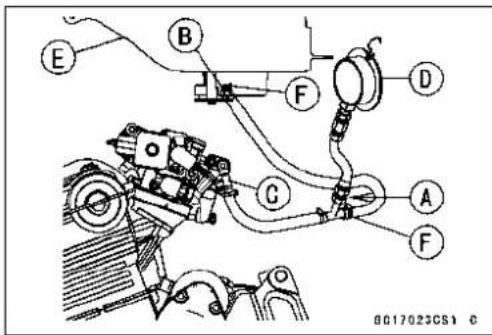
FuelLine
- TurntheignitionswitchON. The fuel pump will turn for 3 seconds, and then stop.
CAUTION
Donotdrivethefuelpumpwithoutthefuelinthe fueltank.
- Measure the fuel pressure with the engine stopped.
FuelPressure
RightafterIgnitionSwitchON,withpumprunning:
Standard:323kPa(3.3kgf/cm²,47psi)
After3secondsfromIgnitionSwitchON,withpump stopped:
Standard:265kPa(2.7kgf/cm²,38psi)(residual fuelpressure)
Thesystemshouldholdtheresidual pressureabout30seconds.
- Starttheengine, andletitidle.
- Measurethefuelpressurewiththeengineidling.
FuelPressure(Idling)
Standard: 333 kPa (3.4 kgf/cm², 48 psi)
NOTE
○ Thegaugeneedlewillfluctuate. Read the pressure at the average of the maximum and minimum indications.
★ If the fuel pressure is normal, the fuel circulation system (fuelpump, pressureregulator, and fuelpassage) is no faults. Check the DF I electronic control system (injectors, sensors, crankshaft sensor, and ECU).
★ If the fuel pressure is much lower than specified, check the following:
FuelLineLeakage
FuelPumpOperation(checkthesoundofthepump)
AmountofFuelFlow(seeFuelFlowRateInspection)
★ If the fuel pressure is much higher than specified, check the following:
DeliveryPipeClogging
InjectorClogging
- Removethefuelpressuregaugeandadapter.
- Installthefueltank(seeFuelTankInstallation).
FuelLine
FuelFlowRateInspection
NOTE
○ Besurethebatteryisfullycharged.
WARNING
Gasolineisextremelyflammableandcanbeexplosiveundercertainconditions.Makesurethearea iswell-ventilatedandfreefromanysourceofflame orsparks;thisincludesanyappliancewithapilot light.Donotsmoke.TurntheignitionswitchOFF. Bepreparedforfuelspillage;anyspilledfuelmust becompletelywipedupimmediately.
- Turntheignitionswitch, and enginestopswitchOFF.
- Waituntiltheenginecoolsdown.
● Prepareaplastichoseoftheinsidediameter7.5mm (0.30in.) andameasuringcylinder. - Removethefueltankbolt(seeFuelTankRemoval).
- Openthefueltankcap[A]tolowerthepressureinthe tank.

natural_image
Close-up of a mechanical component with labeled section A, showing a circular opening and central bore (no text or symbols beyond label)WARNING
Bepreparedforfuelspillage;anyspilledfuelmust becompletelywipedupimmediately. Whenthefuelhoseisdisconnected,fuelspillsout fromthehoseandthepipebecauseofresidual pressure.Coverthehoseconnectionwithapiece ofcleanclothtopreventfuelspillage.
- Connecttheplastichose[A]tothefuelpumpoutletpipe.
- Securetheplastichosewithaclamp[B].
- Runtheothersideoftheplastichoseintothemeasuring cylinder[C].
WARNING
Wipeoffspilledoutfuelimmediately. Besuretoholdthemeasuringcylinderververtical.
- Temporarily install the fueltank and closet the fueltank cap.
- With the engine stopped, turn the ignitions switch ON. The fuel pump should operate for 3 seconds, and then should stop. Repeat this several times until the plastic chose is filled with fuel.

FuelLine
CAUTION
Donotdrivethefuelpumpwithoutthefuelinthe fueltank.
- Measurethedischargefor3secondswiththeplastichose filledwithfuel.
○Repeatthisoperationseveraltimes.
AmountofFuelFlow
Standard:60mLormorefor3seconds
★Ifthefuelflowismuchlessthanthespecified, check thebatterycondition(seeBatterysectionintheElectricalSystemchapter).Ifthebatteryisgood,replace fuelpump.
- Afterinspection, install the fuel tank. (see Fuel Tank Installation).
- Starttheengineandcheckforfuelleakage.
FuelPump
FuelPumpRemoval
CAUTION
Neverdropthefuelpump,especiallyonahardsurface.Suchashocktothepumpcandamageit.
WARNING
Gasolineisextremelyflammableandcanbeexplosiveundercertainconditions.Makesurethearea iswell-ventilatedandfreefromanysourceofflame orsparks;thisincludesanyappliancewithapilot light.Donotsmoke.TurntheignitionswitchOFF. Disconnectthebattery(−)terminal. Tomakefuelspillageminimum,drawthefuelout fromthefueltankwhentheengineiscold.Be preparedforfuelspillage;anyspilledfuelmustbe completelywipedupimmediately.
- Drawthefueloutfromthefueltankwithacommercially availableelectricpump.
- Removethefueltank(seeFuelTankRemoval).
○Becarefuloffuelspillagefromthefueltankssincefuelstill remainsinthefueltankandfuelpump.Plugthefuelpipe ofthefueltank. - Turnthefueltankupsidedown.
- Remove: FuelPumpBolts[A] FuelPump[B]andgasket
- Discardthefuelpumpgasket.
CAUTION
Donotpulltheleadofthefuelpump.Iftheyare pulled,theleadterminalsmaybedamaged.
FuelPumpInstallation
- Removedirtordustfromthefuelpump[A]bylightlyapplyingcompressedair.
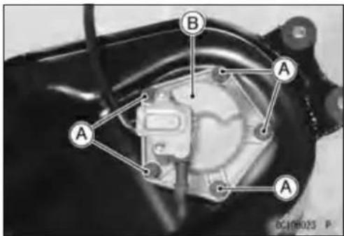
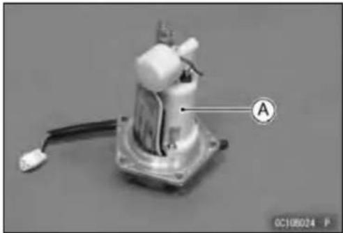
natural_image
Mechanical component with labeled section A and cable, no readable text or symbols beyond labelFuelPump
- Replacethefuelpumpgasket[A]withanewone.

natural_image
Technical line drawing of a mechanical device with labeled component A and reference number 0C10045BS1 (no text or symbols on the diagram itself)- Applyanon-permanentlockingagenttothethreadsof thefuelpumpbolts.
- Tightenthefuelpumpboltstoasnugfit,tightenthem alternatingdiagonally.
Torque-FuelPumpBolts:9.8N·m(1.0kgf·m,87in·lb)
- Tightenthepumpboltsagainalternatingdiagonallyto checkthetightness.
FuelPumpOperationInspection
NOTE
○Besurethebatteryisfullycharged.
○Justlistentothepumpsoundinthefueltanktoconfirm pumpoperation.
- TurntheignitionswitchONandmakesurethatthefuel pumpoperates(makelightsounds)for3seconds,and thenstops.
- TurntheignitionswitchOFF.
★ If the pump does not work as described above, inspect the operating voltage.
FuelPumpOperatingVoltageInspection
NOTE
○Besurethebatteryisfullycharged.
- TurntheignitionswitchOFF.
- Removetheleftsidecover(seeSideCoverRemovalin theFramechapter).
FuelPump
- Connectthehandtester(25VDC)tothefuelpumpconnector[A]withneedleadapterset.
SpecialTools-HandTester:57001-1394
NeedleAdapterSet:57001-1457
○Measuretheoperatingvoltagewiththeenginestopped, andwiththeconnectorjoined.
- TurntheignitionswitchON.
○Thetesterneedleshouldindicatebatteryvoltagefor3 seconds,andthen0V.
PumpOperatingVoltageatPump
ConnectionstoPumpConnectors
Tester(+)→ W/RLead
Tester(-)→ BK/YLead
Operating Voltage at Pump Connector
Standard:BatteryVoltage(12.8Vormore)for3 seconds,andthen0V.
★Ifthereadingstaysonbatteryvoltage,andnevershows 0V.ChecktheECUandfuelpumprelay.
★Ifthevoltageisinspecification,butthepumpdoesn't work,replacethepump.
★Ifthereisstillnobatteryvoltage,checkthepumprelay (seeRelayBoxsectionintheElectricalSystemchapter).
PressureRegulatorRemoval
○Thepressureregulator[A]isbuiltintothefuelpump[B] and cannot be removed.

natural_image
Close-up of mechanical components with labeled parts (A and C) showing no readable text or symbols beyond labels
PumpScreen, FuelFilterCleaning
○Thefuelfilter[A]isbuiltintothepumpandcannotbe cleanedorchecked.
★ If the fuelfilterissuspected of cloggingor being damaged, replace it with the fuelpumpasaset.
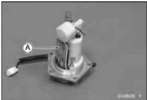
natural_image
Mechanical component with labeled section A and cable, no visible text or symbolsFuelPump
FuelPumpCircuit

flowchart
graph TD
    A["1"] --> B["2"]
    A --> C["3"]
    A --> D["4"]
    B --> E["5"]
    C --> F["6"]
    D --> G["7"]
    E --> H["8"]
    F --> I["9"]
    G --> J["10"]
    H --> K["11"]
    I --> L["12"]
    J --> M["13"]
    K --> N["14"]
    L --> O["15"]
    M --> P["16"]
    N --> Q["17"]
    O --> R["18"]
    P --> S["19"]
    Q --> T["20"]
    R --> U["21"]
    S --> V["22"]
    T --> W["23"]
    U --> X["24"]
    V --> Y["25"]
    W --> Z["26"]
- ECU
- Water-proofJointC
- EngineStopSwitch
- IgnitionSwitch
- IgnitionFuse10A
6.FuelPumpRelay
7. RelayBox
8.MainFuse30A
9.Battery
10.FrameGround
11.FuelPump
FuellInjectors
Removal/Installation
- RefertotheThrottleBodyAssyDisassembly/Assembly.
AudibleInspection
- Starttheengine.
- Applythetipofascrewdriver[A]totheinjector[C].Put thegripendontoyourear, andlistenwhethertheinjector isclickingornot.
○Asoundscope[B]canalsobeused. - Dothesamefortheotherinjectors.
★Ifalltheinjectorsclickataregularintervals,theinjectors aregood. Thetroublemayberelatedtothefuelline, requiringfuelpressureinspection(seeFuelLinesection).
○Theclickintervalbecomesshorterastheenginespeed rises.
★Ifanyinjector(s)doesn'tclick,theDFIcircuitortheinjector issuspect.Perform "FuelInjectorPowerSourceVoltage Inspection",first.

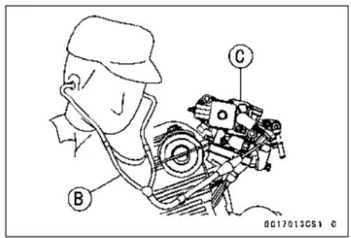
FuelInjectorPowerSourceVoltageInspection
- RemovetheECU(seeECUPowerSupplyInspection).
○DonotdisconnecttheECUconnector. - Connectadigitalmeter[A]totheECUconnector[B],usingtheneedleadapter[C].
SpecialTool-NeedleAdapterSet:57001-1457
○Measure the powersource voltage with the engine stopped, and with the connector joined.
- TurntheignitionswitchON.
InjectorPowerSourceVoltageatECU
Connections:Meter(+)→ W/Y(terminal16)
Meter(-)→ Battery(-)Terminal
ServiceLimit: Voltage(12.6Vormore)

★Ifthemeterdoesn'treadasspecified,checkthefollowing.
MainFuse30A(seeFusesectionintheElectricalSystemchapter)
FuelPumpRelay(seeRelayCircuitInspectioninthe ElectricalSystemchapter)
PowerSourceWiring(see Wiring Diagram below)
TochecktheW/Rleadsbetweentheinjectorconnector andthefuelpumprelay,removethefueltank(seeFuel TankRemoval)andtheleftsidecover(seeSide Cover RemovalintheFramechapter).
★If the power source voltage is normal, check the output voltageoftheinjectors.
FuellInjectors
FuelInjectorOutputVoltageInspection
- TurntheignitionswitchOFF.
- RemovetheECU(seeECUPowerSupplyInspection).
- Connectadigitalvoltmeter[A]totheECUconnector[B] withtheneedleadapterset[C].
SpecialTool-NeedleAdapterSet:57001-1457
InjectorOutputVoltage
Connectionstolnjector#1
Meter(+)→ BL/Rlead(terminal42)
Meter (-) Battery (-) Terminal
Connectionstoljector#2
Meter(+)→ BL/Glead(terminal41)
Meter (-) Battery (-) Terminal
- TurntheignitionswitchON.
OutputVoltageatInjectorConnector
Standard:BatteryVoltage(12.8Vormore)
★ If the output voltage is normal, perform "InjectorSignal Test".
★ Iftheoutputvoltageisoutofthestandard,turntheignition switchOFF,removethefueltank,andchecktheinjector wiringforcontinuity.
InjectorWiringInspection
ECUConnectorInjectorConnectors
Terminal36 → Injector#1Terminal(BL/R)
Terminal35 → Injector#2Terminal(BL/G)
★ If the wiring is good, inspect the resistance of the injectors (see Injector Resistance Inspection).
- Removetheneedleader.
- ApplysiliconesealanttothesealsoftheECUconnector forwaterproofing.
SiliconeSealant(KawasakiBond:56019-120)-Seals of ECUConnectors
InjectorSignalTest
- Preparetwotestlightsetswithmaleterminalsasshown. RatingofBulb[A]:12V×3\~3.4W
TerminalWidth[B]:1.8mm(0.071in.)
TerminalThickness[C]:0.8mm(0.031in.)
CAUTION
Donotuselargerterminalsthanspecifiedabove.A largerterminalcoulddamagetheinjectormainharnessconnector(female),leadingtoharnessrepair orreplacement.
Besuretoconnectbulbsinseries.Thebulbworks as a current limiter to protect the solenoid in the injectorfromexcessivecurrent.


FuellInjectors
- Removethefueltank(seeFuelTankRemoval).
- Removetheaircleanerhousing(seeAirCleanerHousingRemoval)
- Removeconnectorsforinjector[A].
- Connecteachtestlightset[B]totheinjectorsubharness connector[C].
- TurntheignitionswitchON.
- Whilecrankingtheenginewiththestartermotor,watch thetestlights.
★Ifthetestlightsflickeratregularintervals, theinjector circuitintheECU, andthewiringaregood. Perform the "InjectorResistanceInspection".
○Injectorsignalscanbealsoconfirmedbyconnectingthe handtester(×10VAC)insteadofthetestlightsetto theirinjectormainharness(female)connector.Crankthe enginewiththestartermotor,andchecktoseeifthehand oscillatesatregularintervals.
SpecialTool-HandTester:57001-1394
★Ifthetestlightdoesn'tflicker(orthetesterneedledoesn't oscillates),checkthewiringandconnectorsagain.Ifthe wiringisgood,checktheinjectorvoltage.Ifthewiringis good,inspecttheECUforitsgroundandpowersupply (seeECUPowerSupplyInspection).
InjectorResistanceInspection
- Removethefueltank(seeFuelTankRemoval).
- Removetheaircleanerhousing(seeAirCleanerHousingRemoval).
- Disconnecttheconnectorfromtheinjector[A].
- Measure the injector resistance with the hand tester [B].
SpecialTool-HandTester:57001-1394
InjectorResistance
Connectionstoljector
Meter(+)Meter(-)
1:W/R←→ BL/RTerminal
2: W/R ←→ BL/G Terminal
Standard: about 11.7 \~ 12.3 Ω @20°C (68°F)
★If the reading is out of the range, perform the "Injector Unit Test".
★ If thereading is normal, perform the "InjectorUnitTest" for confirmation.
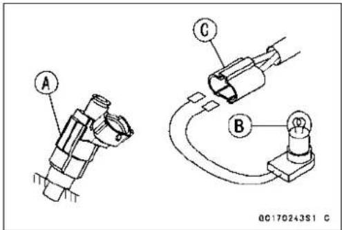
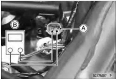
FuellInjectors
InjectorUnitTest
- Usetwoleads[A]andthesametestlightset[B]asin "InjectorSignalTest".
RatingofBulb[C]:12V×(3\~3.4)W
12VBattery[D]
CAUTION
Besuretoconnectthebulbinseries.Thebulb worksasacurrentlimitertoprotectthesolenoid intheinjectorfromexcessivecurrent.
- Connectthetestlightsettotheinjector[E]asshown.
- Openandconnect[F]theendoftheleadtothebattery (-)terminalrepeatedly.Theinjectorshouldclick.
★ If the injectordoes not click, replace the injector.
★ Iftheinjectorclicks, checkthewiringagain. Ifthewiring isgood, replacetheinjector(maybeclogged) or ECU.
InjectorFuelLineInspection
- Remove:
FuelTank(seeFuelRemoval) - Besuretoplaceapieceofclotharoundthefuelhosejoint andthedeliverypipe.
- Insertaminusscrewdriver[A]intotheslitonthejointlock [B].
- Turnthedrivertodisconnectthejointlock.
- Pullthefuelhosejoint[C]outofthedeliverypipe.
- Checktheinjectorfuellineforleakageasfollows: ○Connectacommerciallyavailablevacuum/pressure pump[A]tothenippleofthedeliverypipe[B]with a high-pressurefuelhoseCasshown.
Torque-FuelHoseClampScrews:1.5N·m(0.15kgf·m,13in·lb)
○Applysoapandwatersolutiontotheareas[E]asshown.
- Watching the pressure gauge, squeezethepumplever [F], and build up the pressure until the pressurereaches themaximum pressure.


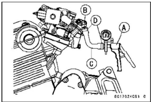
InjectorFuelLineMaximumPressure
Standard: 333 kPa (3.4 kgf/cm², 48 psi)
CAUTION
Duringpressuretesting, donotexceedthemaxi-mumpressureforwhichthesystemisdesigned.
- Watchthegaugeforatleast6seconds.
★ If the pressure holds steady, the system is good.
★ If the pressuredropsatonceorifbubblesarefound in the area, the line is leaking. Replacethedeliverypipe, injectors and related parts.
○Repeat the leak test, and check the fluelline for no leakage. - Installthepumpoutlethose(seeFuelTankInstallation).
- Run the hoses correctly (see Cable, Wire, and Hose Routing section in the Appendix chapter).
FuelInjectorCircuit

flowchart
graph TD
    A["①"] --> B["②"]
    B --> C["③"]
    C --> D["④"]
    D --> E["⑤"]
    E --> F["⑥"]
    F --> G["⑦"]
    G --> H["⑧"]
    H --> I["⑨"]
    I --> J["⑩"]
    J --> K["⑪"]
    K --> L["⑫"]
    L --> M["⑬"]
    M --> N["⑭"]
    N --> O["⑮"]
    O --> P["⑯"]
    P --> Q["⑰"]
    Q --> R["⑱"]
    R --> S["⑲"]
    S --> T["⑳"]
    T --> U["⑪"]
    U --> V["⑫"]
    V --> W["⑬"]
    W --> X["⑭"]
    X --> Y["⑮"]
    Y --> Z["⑯"]
    Z --> AA["⑰"]
    AA --> AB["⑱"]
    AB --> AC["⑲"]
    AC --> AD["⑳"]
    AD --> AE["⑪"]
    AE --> AF["⑫"]
    AF --> AG["⑬"]
    AG --> AH["⑭"]
    AH --> AI["⑮"]
    AI --> AJ["⑯"]
    AJ --> AK["⑰"]
    AK --> AL["⑱"]
    AL --> AM["⑲"]
1.ECU
2.FuellInjectors
3. Water-proof JointC
4. EngineStopSwitch
5. IgnitionSwitch
6. IgnitionFuse10A
- Fuel Pump Relay (for fuel pump and injectors)
8.RelayBox
9.MainFuse30A
10.Battery
11.FrameGround
12.JointConnector
ThrottleGripandCables
ThrottleGripFreePlayInspection
- RefertoThrottleControlSystemInspectioninthePeriodicMaintenancechapter.
ThrottleGripFreePlayAdjustment
- RefertoThrottleControlSystemInspectioninthePeriodicMaintenancechapter.
Throttle Cable Installation
- InstallthethrottlecablesinaccordancewithCable, Wire, and HoseRoutingsectionintheAppendixchapter.
- Installthelowerendsofthethrottlecablesinthecable bracketonthethrottleassyafterinstallingtheupperends ofthethrottlecablesinthegrip.
- Afterinstallation,adjusteachcableproperly.
WARNING
Operationwithincorrectlyroutedorimproperlyadjustedcablescouldresultinanunsaferidingcondition.
ThrottleCableLubrication
- RefertoChassisPartsLubricationinthePeriodicMaintenancechapter.
ThrottleBodyAssy
IdleSpeedInspection
- RefertoIdleSpeedInspectioninthePeriodicMaintenancechapter.
EngineVacuumSynchronizationInspection/Adjustment
- RefertoEngineVacuumSynchronizationInspectionin thePeriodicMaintenancechapter.
HighAltitudePerformanceAdjustment
- Anymodificationisnotnecessaryinthismodelsince theinletairpressuresensorsensesinletairpressure changeduetohighaltitudeandtheECUcompensates thechange.
ThrottleBodyAssyRemoval
WARNING
Gasolineisextremelyflammableandcanbeexplosiveundercertainconditions.Turntheignition switchOFF.Disconnectthebattery(−)cableterminal.Donotsmoke.Makesuretheareas well-ventilatedandfreefromanysourceofflame orsparks;thisincludesanyappliancewithapilot light. Bepreparedforfuelspillage:anyspilledfuelmust becompletelywipedupimmediately.
- Remove: FuelTank(seeFuelTankRemoval)
- Disconnect: MainThrottleSensorConnector[A] FuelHoseLowerEnd[B] VacuumHose[C] SubthrottleSensorActuator[D]Connector
- Disconnect: #1.#2InjectorConnector[A] SubthrottleSensorConnector[B] - Loosen: HolderandDuctClampBolts[C]
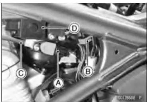
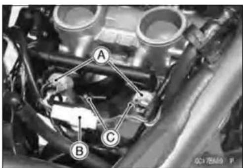
ThrottleBodyAssy
- Loosenthelocknutandscrewinthethrottledcableadjuster fullytogivethecablesplentyofplay.
- Removetherightswitchhousingandtakeouttheacceleratorcableupperend[A]anthedeceleratorcableupper end[B].
- Removethethrottledcablelowerends[A]fromthethrottle pulley.
- Afterremovingthethrottlebodyassy, stuffpiecesoflint-free, cleanclothintothethrottlebodyholders.
CAUTION
Ifdirtgetsintotheengine,excessiveenginewear andpossibleenginedamagewilloccur.
ThrottleBodyAssyInstallation
- Installtheholderclampbolts[A]inthedirections shown with each boltheads[B], facing outwards.
- Installtheaircleanerductclampscrew[A]sothattheir screwheads[B]facetheright.
- Runthevacuumhose(seeCable, Wire, and HoseRoutingsectionintheAppendixchapter).

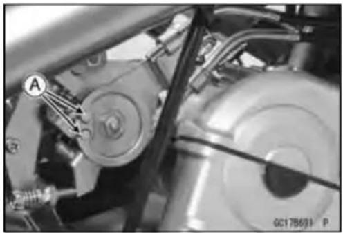
natural_image
Close-up mechanical assembly showing a car wheel and gear mechanism (no visible text or symbols)

ThrottleBodyAssy
- Fittheacceleratorcableend[A]andthedeceleratorcable end[B]intothethrottlepulley.
- Checkfuelleakagefromthethrottlebodyassy.
WARNING
Fuelspilledfromthecarburetorsishazardous.
- Applyathincoatingofgreasetothethrottlecableupper ends.
• Installtheupperendsofthethrottlecablesinthegrip. - Fittheprojection[A]oftherightswitchhousingintothe hole[B]ofthehandlebar.
- Turnthethrottlegripandmakesurethatthethrottlevalves movesmoothlyandreturnbyspringforce.
- Checkthethrottlegripfreeplay(seeThrottleControlSystemInspectioninthePeriodicMaintenancechapter).
WARNING
Operationwithanincorrectlyroutedcablecouldresultinanunsaferidingcondition.
- Adjust:
Throttle Grip Free Play IdleSpeed
ThrottleBodyAssyDisassembly
CAUTION
Donotremove, disassembleor adjust themain throttlesensor[A], subthrottlesensor[B], sub-throttle valve actuator[C], throttle link mechanism [D] and throttle body assy[E], because they are adjusted or set at the manufacturer. Adjustment of these parts could result in poor performance, requiring replacement of the throttle body assy.
- Removethethrottlebodyassy(see ThrottleBodyAssy Removal).
CAUTION
Neverdropethethrottlebodyassy,especiallyona hardsurface.Suchashocktothebodyassycan damageit.


0017018CS1 C
ThrottleBodyAssy
- Remove:
Screws[A]
DeliveryPipe[B]
FuellInjectors[C]

ThrottleBodyAssyAssembly
○ReplacetheO-rings[A]andseals[B]withthenewones.
- Beforeassembling, blowawaydirtordustfromthethrottle bodyanddeliverypipebyapplyingcompressedair.
- ApplyengineoiltothenewO-ringsofeachinjector[C], insertthemintothedeliverypipeandconfirmwhetherthe injectorsturnsmoothlyornot.
- Installtheinjectorsalongwiththedeliverypipeassyinto thethrottlebodies.
- Install the throttle body assy (see Throttle Body Assy Installation).

flowchart
graph TD
    A["Component A"] --> B["Component B"]
    B --> C["Component C"]
    C --> A
    C --> B
    style A fill:#f9f,stroke:#333
    style B fill:#ccf,stroke:#333
    style C fill:#cfc,stroke:#333
AirCleaner
AirCleanerElementRemoval/Installation
- RefertoAirCleanerElementReplacementinthePeriodic Maintenancechapter.
AirCleanerElementInspection
- Removetheaircleanerelement(seeAirCleanerElement ReplacementinthePeriodicMaintenancechapter).
- Visuallychecktheelement[A]fortearsorbreaks.
★Iftheelementhasanytearsorbreaks,replacetheelement.
AirCleanerOilDraining
Adrainhoseisconnectedtothebottomoftheaircleaner todrainwateroroilaccumulatedinthecleanerpart.
- Visuallycheckthedrainhose[A]ifthewateroroilaccumulates.
★Ifanywateroroilaccumulatesinthehose,removethe plug[B]fromthedrainhoseanddrainit.
WARNING
Besuretoreinstallthepluginthedrainhoseafterdraining.Oilontireswillmakethemslipperyandcancauseanaccidentandinjury.
AirCleanerHousingRemoval
- Removedisconnect. Hose(Disconnect)[A] InletAirTemperatureSensorConnector[B] Screws[C] Cover[D]
- Disconnectthebreatherhose[A]ontheuppercrankcase.
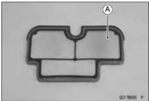
natural_image
Technical diagram of a mechanical part with labeled point A (no text or symbols beyond label)
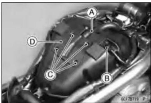
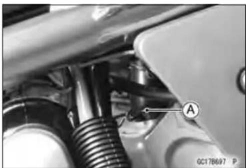
natural_image
Close-up of mechanical components with no visible text or symbolsAirCleaner
- Unscrewthebolts[A]andremovetheaircleanerhousing [B].

AirCleanerHousingInstallation
- Installtheclamponthehose[A]sothatitspinchheads [B]facetheright.
- Installtheclamponthebreatherhose[C]sothatitspinch heads[D]facethefront.

FuelTank
FuelTankRemoval
WARNING
Gasolineisextremelyflammableandcanbeexplosiveundercertainconditions.Makesurethearea iswell-ventilatedandfreefromanysourceofflame orsparks;thisincludesanyappliancewithapilot light.Donotsmoke.TurntheignitionswitchOFF. Bepreparedforfuelspillage;anyspilledfuelmust becompletelywipedupimmediately.
- Remove:
Seat(seeSeatRemovalintheFramechapter) SideCovers(seeSideCoversRemovalintheFrame chapter) FuelTankBolts[A]
- Turntheignitionswitch,andenginestopswitchOFF.
- Waituntiltheenginecoolsdown.
-
Openthefueltankcap[A]tolowerthepressureinthe tank.
○Duringtankremoval, keep the tank cap open to release pressure in the tank. This makes fuel spillage less. -
Drawthefueloutfromthefueltankwithacommercially availablepump[A].
○Useasoftplastichose[B]asapumpinlethoseinorder toinsertthehosesmoothly. - Putthehosethroughthefillopening[C]intothetankand drawthefuelout. Front[D]
WARNING
The fuel could not be removed completely from the fuel tank. Becareful for remained fuel spillage.
- Remove:
LeftSideCover(seeSideCoverRemovalintheFrame chapter) - Disconnectthefuelpumpleadconnector[A]andthetube[B].

natural_image
Close-up of mechanical components with labeled point A (no readable text or symbols beyond label)
natural_image
Close-up of a mechanical component with labeled section A, showing a circular opening and central bore (no text or symbols beyond label)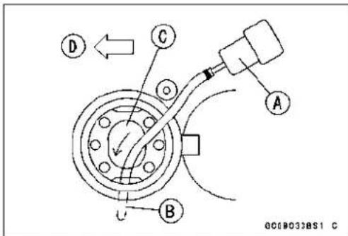

FuelTank
- Besuretoplaceapieceofcloth[A]aroundthefuelhose joint.
-
Insertaminusscrewdriver[B]intotheslit[C]onthejoint lock.
-
Turn[A]thedrivertodisconnectthejointlock[B].
- Pull[C]thefuelhosejointout[D]oftheoutletpipe.
CAUTION
When removing the fuel hose joint, donot apply strong forceto the outlet pipe on the fuel pump. The pipemade from resincould bed damaged.
- Closethefueltankcap.
- Removethefueltank, and placeitonaflatsurface.
○Donotapplytheloadtothefuelpumpoutletportion[A] especiallytheoutletpipemadefromresin.
FuelTankInstallation
- NotetheaboveWARNING(seeFuelTankRemoval).
- Routethehosescorrectly(seeCable, Wire, and Hose RoutingintheAppendixchapter).
-
Check that the rubber dampers[A] are on the frame and the fuel tank.
-
Checkthatthedampers[A]areinplaceonthefueltank aswell.
★ If the dampers are damaged, deteriorated, replace them.

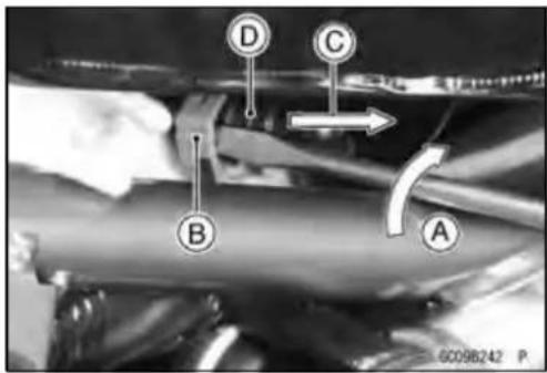

natural_image
Close-up of a mechanical component with a magnified circular detail labeled 'A', no visible text or symbols beyond the label.

FuelTank
- Besurethatthetrimseal[A]isonthefueltank.
ReverseSideofFuelTank[B]
SideCover[C]
Approx.17mm(0.67in.)[D]
Front[E]
- Insert[A]thefuelhosejoint[B]straightontothedelivery pipeuntilthehosejointclicks.
CAUTION
Wheninstallingthefuelhosejoint, donotapply strongforcetotheoutletpipeonthefuelpump. The pipemadefromresincouldbedamaged.
- Push[C]thejointlock[D].
- Pushandpull[A]thehosejoint[B]backandforthmore thantwotimesandmakesureitislockedanddoesn't comeoff.
WARNING
Makesurethehosejointisinstalledcorrectlyonthe deliverypipebyslidingthejoint,orthefuelcould leak.
★ Ifitcomesoff, reinstallthehosejoint.
- Connectthefuelpumpandthefuellevelsensorconnectorsandthebattery(−)cableterminal.
FuelTankandCapInspection
- Visuallyinspectthegasket[A]onthetankcapforany damage.
★Replacethegasketifitisdamaged. - Checktoseeifthewaterdrainpipe[B]inthetankisnot clogged.checkthetankcapbreatheralso.
★Iftheyareclogged,removethetankanddrainit,andthen blowthebreatherfreewithcompressedair.
CAUTION
Donotapplycompressedairtotheairventholes [C]inthetankcap. This could cause damage and clogging of the labyrinth in the cap.

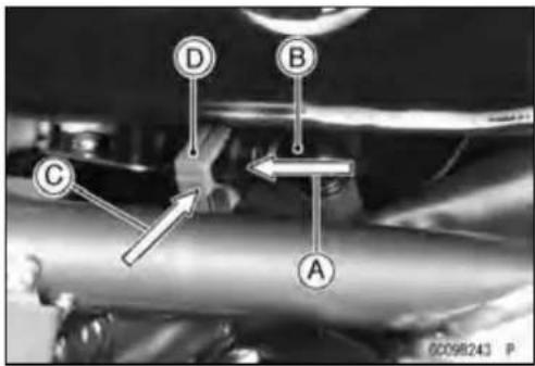
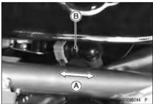

FuelTank
FuelTankCleaning
WARNING
Cleanthetankinawell-ventilatedarea, and take care that there are no sparks or flame any where near the working area. Because of the danger or highly flammable liquids, donot use gasoline or low-flash points solvent st o cleanthetank.
- Removethefueltank(seeFuelTankRemoval).
- Removethefuelpumpinlethoseandthefuelpump(see FuelPumpsection).
- Poursomehigh-flashpointsolventintothefueltankand shakethetanktoremovedirtandfueldeposits.
- Drawthesolventoutofthefueltank.
- Drythetankwithcompressedair.
- Installthefuelpump(seeFuelPumpInstallation).
- Installthefueltank(seeFuelTankInstallation).
CoolingSystem
TableofContents
Exploded View 4-2
Coolant Flow Chart.... 4-4
Specifications 4-6
Special Tools 4-7
Coolant 4-8
Coolant Deterioration Inspection.... 4-8
Coolant Level Inspection 4-8
Coolant Draining 4-8
Coolant Filling 4-8
Pressure Testing 4-8
Cooling System Flushing 4-9
CoolantReserveTankRemoval/Installation....4-9
Water Pump 4-10
Water Pump Removal 4-10
Water Pump Installation 4-10
Mechanical Seal Inspection 4-11
Water Pump Housing Disassembly 4-11
Water Pump Housing Assembly 4-11
Impeller Assembly 4-12
Pump Impeller Inspection 4-12
Radiator 4-13
RadiatorandRadiatorFanRemoval....4-13
Radiator and Radiator Fan Installation 4-14
Radiator Inspection 4-14
Radiator Cap Inspection 4-14
Radiator Filler Neck Inspection 4-15
Thermostat 4-16
Thermostat Removal 4-16
Thermostat Installation.... 4-16
Thermostat Inspection 4-16
Hose and Pipes 4-18
Hose Installation 4-18
Hose Inspection 4-18
Water Temperature Sensor 4-19
WaterTemperatureSensorRemoval/Installation....4-19
WaterTemperatureSensorInspection 4-19
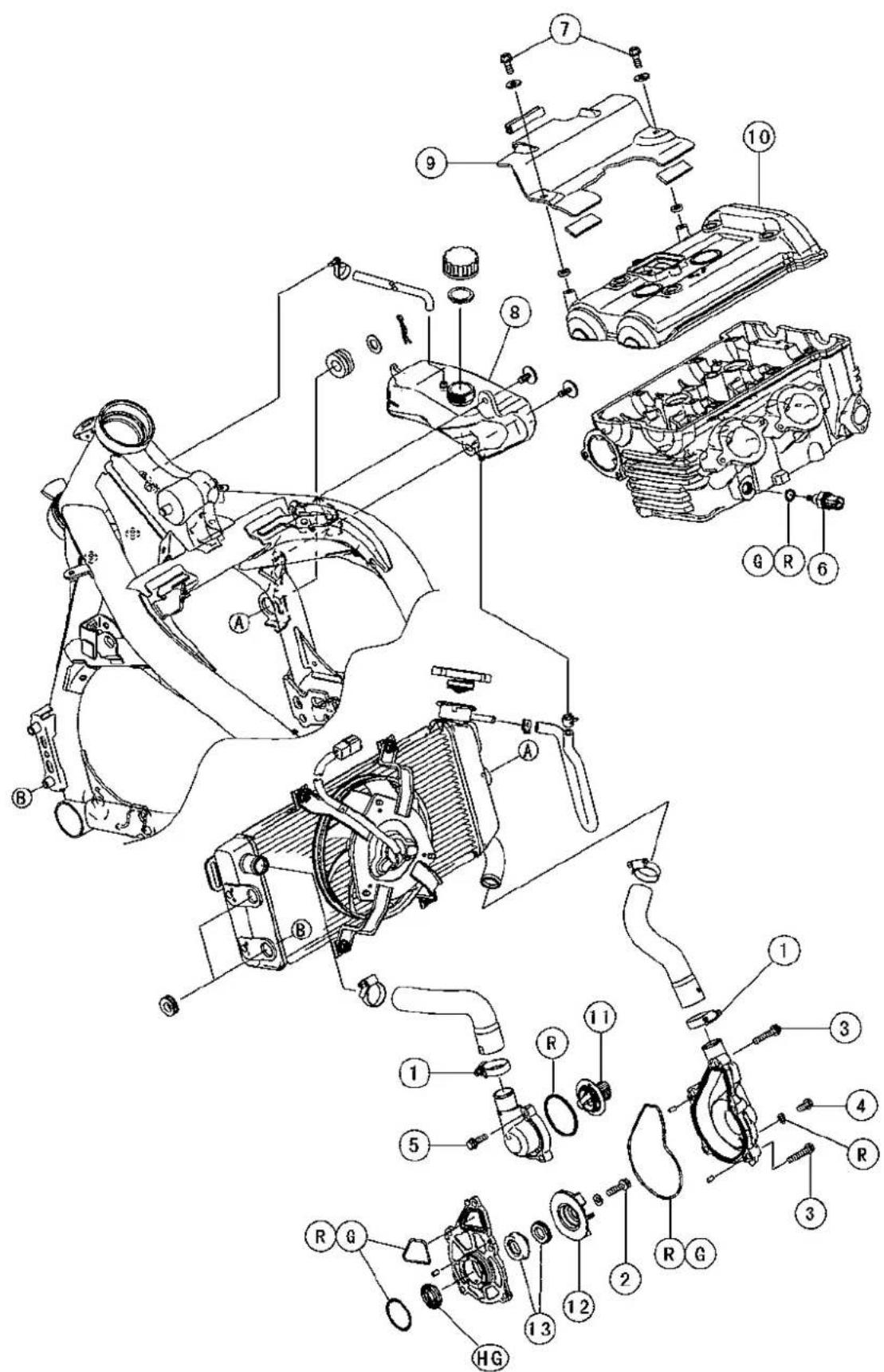
6002056875
ExplodedView
| No. | Fastener | Torque | Remarks | ||
| N·mkgf·mft·lb | |||||
| 1 | RadiatorHoseClampScrews | 2.00.20 | 17in·lb | ||
| 2 | WaterPumpImpellerBolt9.81.087in·lb | ||||
| 3 | WaterPumpCoverBolts9.81.087in·lb | ||||
| 4 | Water Pump Drain Bolt | 7.0 | 0.70 | 62 in·lb | |
| 5 | ThermostatHousingBolts | 9.81.087in·lb | |||
| 6 | Water Temperature Sensor | 12 | 1.2 | 106 in·lb | |
| 7 | Baffle Plate Bolts | 5.9 | 0.60 | 52 in·lb | L |
-
ReserveTank
-
BafflePlate
-
CylinderHeadCover
-
Thermostat
-
WaterPumpImpeller
-
MechanicalSeal
G: Applygrease.
HG: Applyhigh-temperaturegrease.
R: ReplacementParts

CoolantFlowChart
Permanent type antifreeze is used as a coolant to protect the cooling system from rust and corrosion. Whentheenginestarts,thewaterpumpturnsandthecoolantcirculates.
Thethermostatisawaxpellettypewhichopensorcloseswithcoolanttemperaturechanges. The thermostatcontinuouslychangesitsvalveopeningtokeepthecoolanttemperatureattheproperlevel. When coolant temperature is below 80.5 \~ 83.5°C (177 \~ 182°F), the thermostat closes so that the coolantflowisrestrictedthroughtheairbleederhole,causingtheenginetowarmupmorequickly. When coolant temperature is more than 80.5 \~ 83.5°C, the thermostat opens and the coolant flows.
When the coolant temperature goes up beyond 93 \~ 103°C (199 \~ 217°F), the radiator fan relay conductstoooperatetheradiatorfan. Theradiatorfandrawsairthroughtheradiatorcorewhenthere isnotsufficientairflowsuchasatlowspeeds. Thisincreasesupthecoolingactionoftheradiator. When the temperature is below 91°C (196°F) \~ temperature less than ON temperature, the fan relay opensandtheradiatorfanstops.
In this way, this system control the engine temperature within narrow limits where the engine operates most efficiently even if the engine load varies.
Thesystemispressurizedbytheradiatorcaptosuppressboilingandtheresultantairbubbles whichcancauseengineoverheating.Astheenginewarmsup,thecoolantintheradiatorandthe waterjacketexpands.Theexcesscoolantflowsthroughtheradiatorcapandhosetothereservetank tobestoredtheretemporarily.Conversely,astheenginecoolsdown,thecoolantintheradiatorand thewaterjacketcontracts,andthestoredcoolantflowsbacktotheradiatorfromthereservetank.
Theradiatorcaphastwovalves.Oneisapressurevalvewhichholdsthepressureinthesystem when the engine is running. When the pressure exceeds 112.3 \~ 141.7 kPa (1.15 \~ 1.45 kgf/cm², 16.3 \~ 20.5 psi), the pressure valve opens and releases the pressure to the reserve tank. As soon as pressure escapes, the valve closes, and keeps the pressure at 112.3 \~ 141.7 kPa (1.15 \~ 1.45 kgf/cm², 16.3 \~ 20.5 psi). When the engine cools down, another small valve (vacuum valve) in the capopens.Asthecoolantcools,thecoolantcontractstoformavacuuminthesystem.Thevacuum valveopensandallowsthecoolantfromthereservetanktoentertheradiator.
Specifications
| ItemStandard | |
| CoolantProvidedwhenShippingType(Recommended)Permanenttype | ofantifreeze(softwaterandethyleneglycolpluscorrosionandrustinhibitorchemicalsforaluminumenginesandradiators) |
| ColorGreenMixedRatioSoftwater50%,coolant50%FreezingPointTotalAmount | -35°C(-31°F)1.2L(1.3USqt)(reservetankfulllevel,includingradiatorandengine) |
| RadiatorCapRelief Pressure | 112.3 ~ 141.7 kPa (1.15 ~ 1.45 kgf/cm2, 16.3 ~ 20.5 psi) |
| ThermostatValve Opening TemperatureValveFullOpeningLift8mm(0.31in.)or | 80.5 ~ 83.5°C (177 ~ 182°F)more@95°C(203°F) |
SpecialTools
BearingDriverSet: 57001-1129
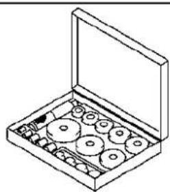
natural_image
Isometric line drawing of a mechanical device with multiple circular components and a rectangular opening (no text or symbols)ST571129ST C
OilSealDriver: 57001-1660

natural_image
Simple line drawing of a cylindrical mechanical part (no text or symbols)\$1571660ST C
Coolant
CoolantDeteriorationInspection
- Removetherightcenterfairingcover(seeCenterFairing RemovalintheFramechapter).
- Visuallyinspectthecoolant[A]inthereservetank.
★Ifwhitishcotton-likewaftsareobserved,aluminumparts inthecoolingsystemarecorroded.Ifthecoolantis brown,ironorsteelpartsarerusting.Ineithercase,flush thecoolingsystem.
★Ifthecoolantgivesoffanabnormalsmell,checkfora coolingsystemleak.Itmaybecausedbyexhaustgas leakingintothecoolingsystem.
CoolantLevelInspection
- RefertoCoolantLevelinthePeriodicMaintenancechapter.
CoolantDraining
- RefertoCoolantChangeinthePeriodicMaintenance chapter.
CoolantFilling
- RefertoCoolantChangeinthePeriodicMaintenance chapter.
Pressure Testing
- Removethereservetank(seeCoolantChangeinthePeriodicMaintenancechapter).
- Removetheradiatorcap, and installacoolingsystem pressuretester[A]onthefillerneck[B].
NOTE
○ Wetthecapsealingsurfaceswithwaterorcoolantto preventpressureleaks.
- Build up pressure in the system carefully until the pressurereaches141.7kPa(1.45kgf/cm²,20.5psi).
CAUTION
Duringpressuretesting, donotexceedthepressureforwhichthesystemisdesigned. Themaximumpressureis141.7kPa(1.45kgf/cm²,20.5psi).
- Watchthegaugeforatleast6seconds.
★Ifthepressureholdssteady,thesystemisallright.
★If the pressuredrops and no external source is found, check for internal leaks. Droplets in the engine oil indicate internal leakage. Check the cylinder headgasket and the waterpump. - Removethepressuretester,replenishthecoolant,and installtheradiatorcap.

natural_image
Close-up of a white plastic container with labeled component A, mounted on a mechanical vehicle (no visible text or symbols beyond label)
Coolant
CoolingSystemFlushing
Overaperiodoftime, thecoolingsystem accumulates rust, scale, and lime in the water jacket and radiator. When this accumulation is suspected or observed, flush the coolingsystem. If this accumulation is not removed, it will clog up the water passage and consider ablereducetheefficiency of the coolingsystem.
- Drainthecoolingsystem(seeCoolantChangeinthePeriodicMaintenancechapter).
- Fillthecoolingsystemwithfreshwatermixedwithaflushingcompound.
CAUTION
Donotuseaflushingcompoundwhichisharmfulto thealuminumengineandradiator.Carefullyfollow theinstructionssuppliedbythemanufacturerofthe cleaningproduct.
- Warmuptheengine, and runitatnormaloperatingtemperatureforabouttenminutes.
- Stoptheengine, anddrainthecoolingsystem.
- Fillthesystemwithfreshwater.
- Warmuptheengineanddrainthesystem.
- Repeat the previous wostepsoncemore.
- Fillthesystemwithapermanenttypecoolantandbleed theairfromthesystem(seeCoolantChangeinthePeriodicMaintenancechapter).
CoolantReserveTankRemoval/Installation
- Thecoolantreservetankisremovedandinstalledduringcoolantchange(seeCoolantChangeinthePeriodicMaintenancechapter).
WaterPump
WaterPumpRemoval
- Drainthecoolant(seeCoolantChangeinthePeriodic Maintenancechapter).
- Loosentheclampandremovetheradiatorhose[A]from thewaterpumpcover[B].
-
Removethewaterpumpcoverbolts[C].
-
Shiftthetransmissioninto1stgear.
- Whileapplyingtherearbrake,removethewaterpump impellerbolt[A].
- Remove: Impeller[B] WaterPumpHousing[C]
WaterPumpInstallation
- Wheninstallingthewaterpumpimpellerbolt,shiftthe transmissioninto1stgearandapplytherearbrake.
- ReplacetheO-rings[A]onthewaterpumphousingwith newonesandapplygreasethem.
- Applyhightemperaturegreasetothelipsofthewaterpumphousingoilseal[B].
- Besurethatthedowelpin[A]isinposition.
• Installthewaterpumphousing.
- Tighten: Torque-WaterPumpImpellerBolt:9.8N·m(1.0kgf·m,87 in·lb)
- ReplacetheO-ring[A]onthewaterpumpcoverwitha newoneandgreaseit.


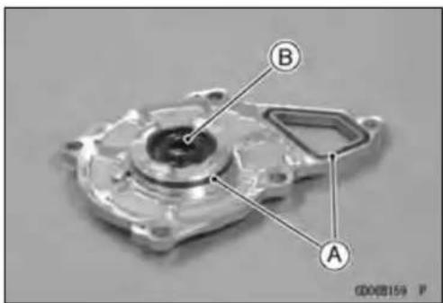
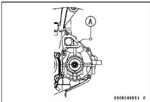
natural_image
Technical line drawing of a mechanical assembly with no visible text or symbols
natural_image
Cross-sectional view of a mechanical component with labeled point A (no text or symbols beyond label)WaterPump
- Installthewaterpumpcover, being careful of the two dowelpins[A].
Torque-WaterPumpCoverBolts:9.8N·m(1.0kgf·m,87in·lb)

natural_image
Mechanical assembly diagram showing a gear and pump component with labeled parts (no readable text or symbols)MechanicalSealInspection
- Visuallyinspectthemechanicalseal.
★Ifanyoneofthepartsisdamaged, replacethemechanicalsealasaunit.
○Thesealingseatandrubbersealmayberemovedeasily byhand.
[A]ImpellerSealingSeatSurface
[B]RubberSeal
[C]MechanicalSealDiaphragm
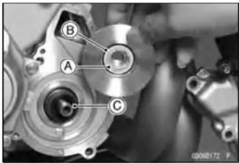
WaterPumpHousingDisassembly
CAUTION
Becarefulnottodamagethesealingsurfaceofthe mechanicalseal.
- Taketheoilseal[A]outofthehousing[B]withahook[C].
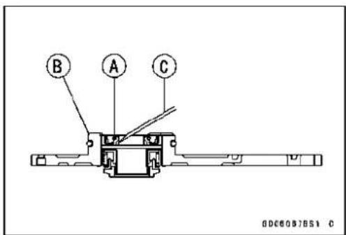
- Pressthemechanicalseal[A]outofthehousingwitha bearingdriver[B].
SpecialTool-BearingDriverSet:57001-1129
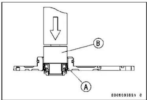
WaterPumpHousingAssembly
- Applyahighttemperaturegrease[A]tothenewoilseal [B].
- Presstheoilsealintothehousingwithabearingdriverso thatthesealsurfaceisflush[C]withtheendofthehole.
- Pressthenewmechanicalsealintothehousingwiththe oilsealdriver[D]untilitsflange[E]touchesthesurface [F]ofthehousing.
SpecialTool-OilSealDriver:57001-1660
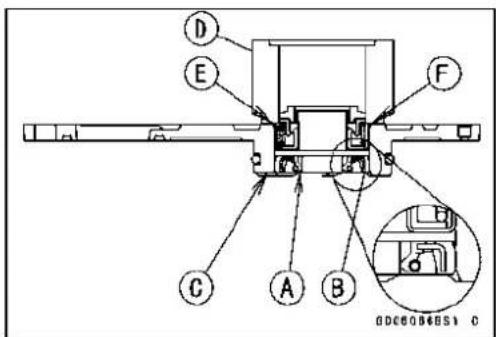
WaterPump
ImpellerAssembly
- Cleantheslidingsurfaceofthemechanicalsealwitha highflash-pointsolvent, and applyalittlecoolanttothe slidingsurfacetogivethemechanicalsealinitiallubrication.
- Applycoolanttothesurfacesoftherubberseal[A]and sealingseat[B], and installtherubbersealandsealing seatintotheimpellerbypassingthembyhanduntilthe seatstopsatthebottomofthehole.
PumpImpellerInspection
- Visuallychecktheimpeller[A].
★Ifthesurfaceiscorroded,orifthebladesaredamaged, replacetheimpeller.
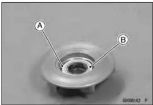

natural_image
Mechanical component with labeled parts (A and P), no readable text or symbols beyond labelsRadiator
RadiatorandRadiatorFanRemoval
- Drainthecoolant(seeCoolantChangeinthePeriodic Maintenancechapter).
- Remove: Left/RightCenterFairing(seeCenterFairinginthe Framechapter) ReserveTank(seeCoolantChangeinthePeriodicMaintenancechapter) RadiatorFanMotorConnectorA RadiatorHoseClampScrewB
- Loosen: RadiatorHoseClampScrew[A] - Remove: CotterPin[B]
- Pull[A]theradiator[B]towardtheleft,notingthebaffle plate[C]onthecylinderheadcover.
CAUTION
Donottouchtheradiatorcore. This could damage theradiatorfins, resulting in loss of cooling efficiency.
- Ifnecessary, remove: RadiatorFanMountingBolts[A] RadiatorFan[B]


Radiator
RadiatorandRadiatorFanInstallation
- Installthegrommet[A]sothatitslargesidefacesthe front.
• Installtheradiator[B]totheframe.
○Align[C]theprojectionontheradiatorwiththeholeon theframe.
○Align[D] the projection on the framework with radiator.
○Notethebaffleplateonthecylinderheadcoverwhen intallingtheradiator.
○Positiontheradiatorhoseclampscrews[E]asshown.

RadiatorInspection
- Checktheradiatorcore.
★Ifthereareobstructionstoairflow,removethem.
★Ifthecorrugatedfins[A]aredeformed,carefully straightenthem.
★Iftheairpassagesoftheradiatorcoreareblockedmore than20%byunremovableobstructionsorirreparablydeformedfins,replacetheradiatorwithanewone.
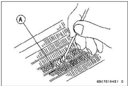
CAUTION
Whencleaningtheradiatorwithsteamcleaner, be carefulofthefollowingtopreventradiatorordamage: Keepthesteamgun[A]awaymorethan0.5m(1.6 ft)[B]fromtheradiatorcore.
HoldthesteamgunperpendicularCtothecoresurface.
Runthesteamgun, following the core find direction.

RadiatorCapInspection
- Remove:
ReserveTank(seeCoolantChangein thePeriodicMaintenancechapter) RadiatorCap - Checktheconditionofthebottom[A]andtop[B]valve sealsandvalvespring[C].
★Ifany oneofthemshowsvisibledamage, replacethecap withanewone.

Radiator
- Installthecap[A]onacoolingsystempressuretester[B].
NOTE
○Wetthecapsealingsurfaceswithwaterorcoolantto preventpressureleaks.
- Watching the pressure gauge, pump the pressure tester to build up the pressure until the relief valve opens: the gaugeneedleflicks downward. Stoppumping and measureleak time at once. There lief valvemustopen within the specified range in the table below and the gauge hand must remain within the same range at least 6 seconds.

RadiatorCapReliefPressure
Standard: 112.3 \~ 141.7 kPa (1.15 \~ 1.45 kgf/cm², 16.3 \~ 20.5psi)
★ Ifthecapcannotholdthespecifiedpressureorifitholds toomuchpressure,replaceitwithanewone.
RadiatorFillerNeckInspection
- Removethereservetank(seeCoolantChangeinthePeriodicMaintenancechapter).
- Removetheradiatorcap.
- Checktheradiatorfillerneckforsignsofdamage.
- Checktheconditionofthetopandbottomsealingseats [A]inthefillerneck. They must besmoothandcleanfor theradiatorcaptofunctionproperly.

Thermostat
ThermostatRemoval
- Drainthecoolant(seeCoolantChangeinthePeriodic Maintenancechapter).
- Remove: LeftCenterFairing(seeCenterFairingRemovalinthe Framechapter) ThermostatHosingBolts[A] ThermostatHosing[B]
- Pullthethermostat[A]outofthecylinderhead.
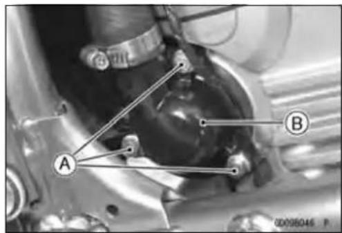

natural_image
Close-up mechanical assembly showing a rotating component with labeled point A (no readable text or symbols)ThermostatInstallation
- Installthethermostat[A]inthecylinderheadsothatthe airbleederhole[B]isontop.
- InstallanewO-ringintothehousingandapplygreaseit.
- Tighten:
Torque-ThermostatHosingBolts:9.8N·m(1.0kgf·m,87in·lb)
- Filltheradiatorwithcoolant(seeCoolantChangeinthe PeriodicMaintenancechapter).
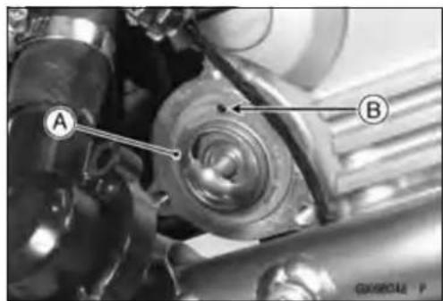
ThermostatInspection
- Removethethermostat, and inspect the thermostat valve [A] at room temperature.
★Ifthevalveisopen, replacethethermostatwithanew one.
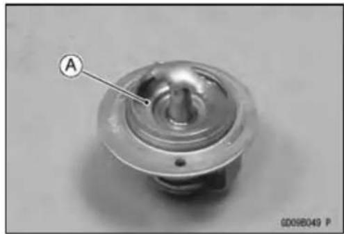
natural_image
Close-up of a metallic mechanical component with a labeled section (A) and reference number 60098049 P (no text or symbols on the object itself)Thermostat
- Tocheckvalveopeningtemperature, suspendthethermostat[A]inacontainerofwaterandraisethetemperatureofthewater.
○Thethermostatmustbecompletelysubmergedandmust nottouchthecontainersidesorbottom.Suspendanaccuratethermometer[B]inthewatersothattheheatsensitiveportions[C]arelocatedinalmostthesamedepth. Itmustnottouchthecontainer,either.
★ If themeasurement is out of the specified range, replace the thermostat with anewone.
ThermostatValveOpeningTemperature
80.5 \~ 83.5°C (177 \~ 182°F)

HoseandPipes
HoseInstallation
- Install the hoses and pipes, being careful to follow bending direction. Avoid sharp bending, kinking, flattening or twisting.
- Runthehoses(seeCable, Wire, and HoseRoutingsectionintheAppendixchapter).
- Installtheclamp[A]asnearaspossibletothehoseend tocleartheraisedribofthefitting. This will prevent the hoses from working loose.
○Theclampscrewsshouldbepositionedcorrectlytopreventtheclampsfromcontactingtheotherparts.
Torque-RadiatorHoseClampScrews:2.0N·m(0.20kgf·m, 17in·lb)
HoseInspection
- RefertoCoolingHoseandConnectionInspectioninthe PeriodicMaintenancechapter.

WaterTemperatureSensor
CAUTION
Thewatertemperaturesensorshouldneverbeallowedtofallonahardsurface.Suchashocktothe watertemperaturesensorcandamageit.
WaterTemperatureSensorRemoval/Installation
- RefertoWaterTemperatureSensorRemoval/Installation intheFuelSystem(DFI)chapter. WaterTemperatureSensor[A]

natural_image
Close-up mechanical assembly showing gears and shafts with a labeled component 'A' (no readable text or symbols beyond label)WaterTemperatureSensorInspection
- RefertoWaterTemperatureSensorInspectioninthe ElectricalSystemchapter.
EngineTopEnd
TableofContents
ExplodedView....5-2
Specifications....5-7
SpecialToolsandSealant......5-9
CleanAirSystem....5-11
AirSuctionValveRemoval......5-11
AirSuctionValveInstallation......5-11
AirSuctionValveInspection......5-11
AirSwitchingValveRemoval......5-11
AirSwitchingValveInstallation....5-12
Air Switching Valve Operation Test....5-12
AirSwitchingValveUnitTest......5-12
CleanAir System Hose Inspection....5-12
CylinderHeadCover....5-13
CylinderHeadCoverRemoval....5-13
CylinderHeadCoverInstallation .5-13
CamshaftChainTensioner....5-14
Camshaft Chain Tensioner Removal....5-14
Camshaft Chain Tensioner Installation....5-14
Camshaft,CamshaftChain....5-15
CamshaftRemoval....5-15
CamshaftInstallation....5-15
Camshaft and Sprocket Assembly....5-18
Camshaft,CamshaftCapWear...5-18
CamshaftRunout 5-19
CamWear....5-19
CamshaftChainRemoval......5-19
CylinderHead....5-20
CylinderCompression Measurement....5-20
CylinderHeadRemoval....5-21
CylinderHeadInstallation....5-22
CylinderHeadWarp....5-24
Valves....5-25
ValveClearanceInspection .....5-25
ValveClearanceAdjustment......5-25
ValveRemoval 5-25
ValveInstallation 5-25
ValveGuideRemoval 5-25
ValveGuideInstallation .....5-26
Valve-to-Guide Clearance Measurement (Wobble Method)....5-26
ValveSeatInspection 5-27
ValveSeatRepair....5-27
Cylinder, Pistons....5-32
CylinderRemoval....5-32
CylinderInstallation....5-32
PistonRemoval....5-32
PistonInstallation....5-33
CylinderWear....5-34
PistonWear....5-34
PistonRing, PistonRing Groove Wear....5-35
PistonRingGrooveWidth......5-35
PistonRingThickness....5-35
PistonRingEndGap....5-36
ThrottleBodyHolder 5-37
ThrottleBodyHolderInstallation..5-37
Muffler....5-38
Muffler BodyRemoval......5-38
ExhaustPipeRemoval......5-38
Muffler Body and Exhaust Pipe Installation....5-39
ExplodedView

ExplodedView
| No.Fastener | Torque | Remarks | |||
| N·mkgf·mft·lb | |||||
| 1 | AirSuctionValveCoverBolts | 9.81.087in·lb | |||
| 2CylinderHeadCoverBolts9.81.087in·lb | |||||
| 3 | Camshaft Cap Bolts | 12 | 1.2 | 106 in·lb | S |
| 4 | Cylinder Head Bolts (M10 New Bolts) | 54 | 5.5 | 40 | MO, S |
| Cylinder Head Bolts (M10 Used Bolts) | 49 | 5.0 | 36 | MO, S | |
| 5 | Cylinder Head Bolts (M6) | 12 | 1.2 | 106 in·lb | S |
| 6 | Throttle Body Holder Bolts | 12 | 1.2 | 106 in·lb | |
| 7 | Rear Camshaft Chain Guide Bolts | 20 | 2.0 | 15 | L |
| 8 | Camshaft Chain Tensioner Mounting Bolts | 9.8 | 1.0 | 87 in·lb | |
| 9 | CamshaftChainTensionerCapBolt | 202.0 | 15 | ||
| 10 | Spark Plugs | 15 | 1.5 | 11 | |
| 11 | Camshaft Sprocket Bolts | 15 | 1.5 | 11 | L |
| 12 | Baffle Plate Bolts | 5.9 | 0.60 | 52 in·lb | L |
L: Applyanon-permanentlockingagent.
M:Applymolybdenumdisulfidegrease.
MO:Applymolybdenumdisulfideoilsolution.
(mixtureoftheengineoilandmolybdenumdisulfidegreaseinaweightratio10: 1)
R:ReplacementParts
S: Followthespecifictighteningsequence.
SS:Applysiliconesealant.
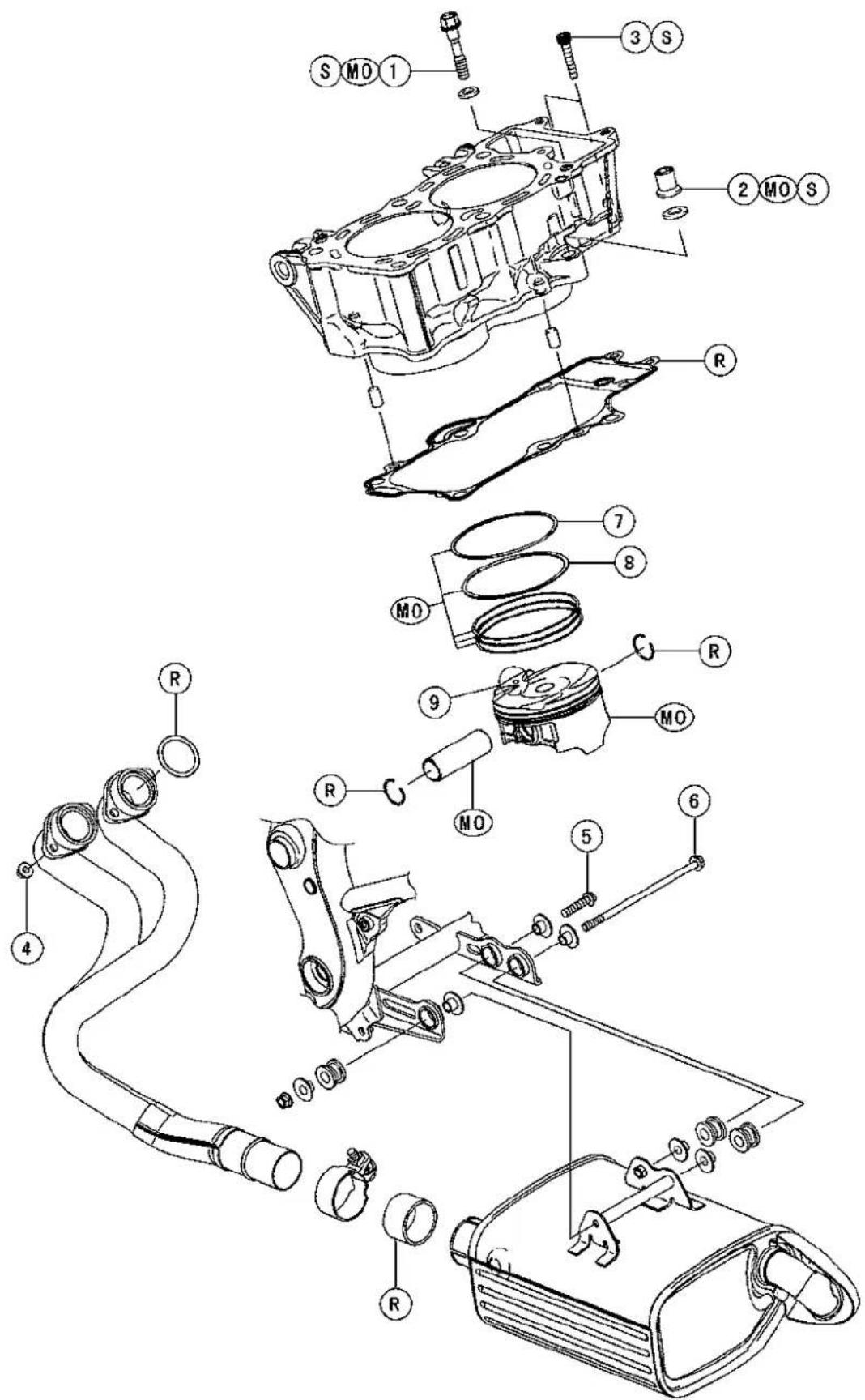
GE02200B75 C
ExplodedView
| No.Fastener | Torque | Remarks | |||
| N·mkgf | mft·lb | ||||
| 1 | CylinderBolt(M8) | 27.52.820 | MO,S | ||
| 2 | Cylinder Nut (M10) | 49 | 5.0 | 36 | MO,S |
| 3 | Cylinder Bolts (M6) | 12 | 1.2 | 106 in·lb | S |
| 4ExhaustPipeManifoldHolderNuts171.712 | |||||
| 5 | Muffler Body Mounting Bolt (Front) | 20 | 2.0 | 15 | |
| 6 | Muffler Body Mounting Bolt (Rear) | 20 | 2.0 | 15 | |
- "R"marked sidefaces up.
- "RN"marked sidefacesup.
- Hollowmark facesforward.
MO: Applymolybdenumdisulfideoilsolution.
(mixture of the engine oil and molybdenum disulfide grease in a weight ratio 10 : 1)
R: ReplacementParts
Exhaust System ER650A6F
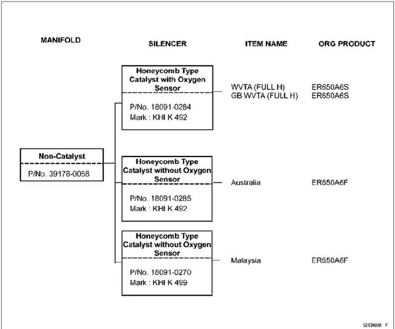
flowchart
graph TD
    A["MANIFOLD"] --> B["Non-Catalyst"]
    A --> C["SILENCER"]
    C --> D["Honeycomb Type Catalyst with Oxygen Sensor"]
    D --> E["P/No. 18091-0284\nMark : KHI K 492"]
    C --> F["Honeycomb Type Catalyst without Oxygen Sensor"]
    F --> G["P/No. 18091-0285\nMark : KHI K 492"]
    C --> H["Honeycomb Type Catalyst without Oxygen Sensor"]
    H --> I["P/No. 18091-0270\nMark : KHI K 499"]
    D --> J["ITEM NAME: WVTA (FULL H), GB WVTA (FULL H)"]
    F --> K["Australia"]
    H --> L["Malaysia"]
    J --> M["ORG PRODUCT: ER650A6S, ER650A6S"]
    L --> N["ORG PRODUCT: ER650A6F"]
Full: Full Power
H: HoneycombTypeCatalyst
GB: UnitedKingdom Model
ExplodedView
Silencer[C]withHole[A]forOxygenSensor[B]
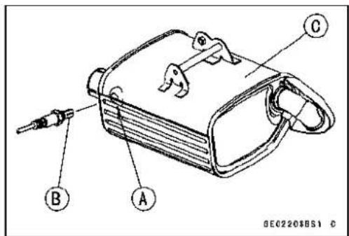
Specifications
| ItemStandardServiceLimit | ||
| Camshafts | ||
| CamHeight: | ||
| Exhaust | 35.843 ~ 35.957 mm (1.4111 ~ 1.4156 in.) | 35.74 mm (1.4071 in.) |
| Inlet | 36.543 ~ 36.657 mm (1.4387 ~ 1.4432 in.) | 36.44mm(1.4346in.) |
| CamshaftJournal,Camshaft CapClearance | 0.028 ~ 0.071 mm (0.0011 ~ 0.0028 in.) | 0.16 mm (0.0063 in.) |
| CamshaftJournalDiameter | 23.950~ 23.972mm(0.9429~ 0.9438 in.) | 23.92mm(0.942in.) |
| CamshaftBearingInside Diameter | 24.000 ~ 24.021 mm (0.9449 ~ 0.9457 in.) | 24.08mm(0.948in.) |
| Camshaft Runout | TIR 0.02 mm (0.0008 in.) or less | TIR 0.1 mm (0.004 in.) |
| CylinderHead | ||
| CylinderCompression | (UsableRange)961~ 1471kPa(9.8~ 15.0kgf/cm2, 139~ 213psi)@400r/min(rpm) | -- -- |
| Cylinder Head Warp | -- -- | 0.05 mm (0.002 in.) |
| Valves | ||
| Exhaust | 0.22 ~ 0.31 mm (0.0087 ~ 0.0122 in.) | -- -- |
| Inlet | 0.15 ~ 0.21 mm (0.0059 ~ 0.0083 in.) | -- -- |
| ValveHeadThickness: | ||
| Exhaust | 0.8mm(0.031in.) | 0.5mm(0.020in.) |
| Inlet | 0.5 mm (0.020 in.) | 0.25 mm (0.0098 in.) |
| ValveStemBend | TIR0.01mm(0.0004in.)orless | TIR0.05mm (0.002in.) |
| ValveStemDiameter: | ||
| Exhaust | 4.455 ~ 4.470 mm (0.1754 ~ 0.1760 in.) | 4.44 mm (0.175 in.) |
| Inlet | 4.475 ~ 4.490 mm (0.1762 ~ 0.1768 in.) | 4.46 mm (0.176 in.) |
| ValveGuideInsideDiameter: | ||
| Exhaust | 4.500 ~ 4.512 mm (0.1772 ~ 0.1776 in.) | 4.58 mm (0.180 in.) |
| Inlet | 4.500 ~ 4.512 mm (0.1772 ~ 0.1776 in.) | 4.58 mm (0.180 in.) |
| Valve/ValveGuideClearance (WobbleMethod): | ||
| Exhaust | 0.07 ~ 0.14 mm (0.0028 ~ 0.0055 in.) | 0.27 mm (0.0106 in.) |
| Inlet | 0.02 ~ 0.08 mm (0.0008 ~ 0.0032 in.) | 0.22 mm (0.0087 in.) |
| Valve Seat Cutting Angle | 45°, 32°, 55°, 60° | -- -- |
| ValveSeatingSurface: | ||
| Width: | ||
| Exhaust | 0.5 ~ 1.0 mm (0.020 ~ 0.039 in.) | -- -- |
| Inlet | 0.5~ 1.0mm(0.020~ 0.039in.) | -- -- |
| OutsideDiameter: | ||
| Exhaust | 27.6 ~ 27.8 mm (1.087 ~ 1.094 in.) | -- -- |
| Inlet | 32.6 ~ 32.8 mm (1.283 ~ 1.291 in.) | -- -- |
Specifications
| ItemStandardServiceLimit | ||
| ValveSpringFreeLength:Exhaust41.91mm(1.650in.)40.3mm(1.587in.)Inlet41.91mm(1.650in.)40.3mm(1.587in.) | ||
| Cylinder,Pistons | ||
| CylinderInsideDiameter | 82.994 ~ 83.006 mm (3.2675 ~ 3.2679 in.) | 83.10mm(3.2716in.) |
| PistonDiameter | 82.969 ~ 82.984 mm (3.2665 ~ 3.2671 in.) | 82.82mm(3.2606in.) |
| Piston/Cylinder Clearance | 0.010 ~ 0.037 mm (0.0004 ~ 0.0015 in.) | -- -- |
| PistonRing/GrooveClearance:Top | 0.03 ~ 0.07 mm (0.0012 ~ 0.0028 in.) | 0.17 mm (0.0067 in.) |
| Second | 0.02 ~ 0.06 mm (0.0008 ~ 0.0024 in.) | 0.16 mm (0.0063 in.) |
| PistonRingGrooveWidth:Top | 0.92 ~ 0.94 mm (0.0362 ~ 0.0370 in.) | 1.02 mm (0.040 in.) |
| Second | 1.01 ~ 1.03 mm (0.0398 ~ 0.0406 in.) | 1.11 mm (0.044 in.) |
| PistonRingThickness:Top | 0.87 ~ 0.89 mm (0.0342 ~ 0.0350 in.) | 0.80 mm (0.031 in.) |
| Second | 0.97 ~ 0.99 mm (0.0382 ~ 0.0390 in.) | 0.90 mm (0.035 in.) |
| PistonRingEndGap:Top | 0.25 ~ 0.40 mm (0.0098 ~ 0.0157 in.) | 0.7 mm (0.028 in.) |
| Second | 0.40 ~ 0.55 mm (0.0157 ~ 0.0217 in.) | 0.8 mm (0.031 in.) |
SpecialToolsandSealant
CompressionGauge,20kgf/cm²: 57001-221

natural_image
Technical line drawing of a pressure gauge with a valve, shown without any text or symbolsValveSpringCompressorAssembly: 57001-241
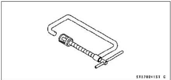
natural_image
Line drawing of a mechanical clamp or spring-loaded component (no text or symbols)ValveSeatCutter,45°-35: φ 57001-1116

natural_image
Isometric line drawing of a cylindrical mechanical part with concentric rings (no text or symbols)ValveSeatCutter,32°-30: 57001-1120

natural_image
Simple line drawing of a cylindrical mechanical part with concentric rings (no text or symbols)ValveSeatCutter,32°-35: φ 57001-1121

natural_image
Isometric line drawing of a cylindrical mechanical part with concentric rings and textured surface (no text or symbols)ValveSeatCutter,60°-30:φ 57001-1123

natural_image
Simple line drawing of a conical object with a circular top and textured base (no text or symbols)ValveSeatCutterHolderBar: 57001-1128

natural_image
Simple line drawing of a cylindrical object with no text or symbolsValveSeatCutter,45°-30:φ 57001-1187
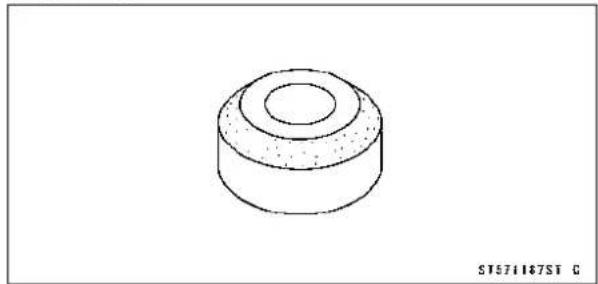
natural_image
Simple line drawing of a cylindrical mechanical part with concentric rings and a central hole (no text or symbols)ValveSeatCutter,55°-35:φ 57001-1247

natural_image
Simple line drawing of a conical object with a circular top and textured base (no text or symbols)ValveSpringCompressorAdapter,21φ 57001-1272

natural_image
Technical line drawing of a mechanical component (no text or symbols)5-10ENGINETOPEND
SpecialToolsandSealant
CompressionGaugeAdapter, M10×1.0: 57001-1317
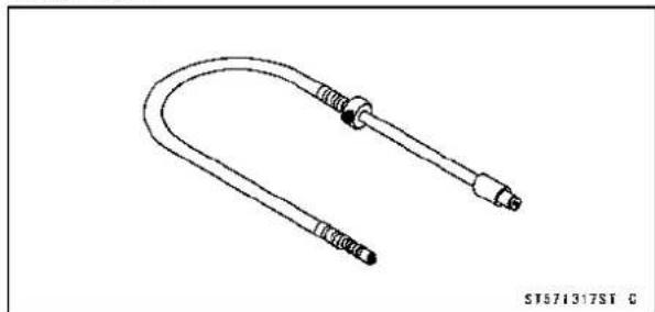
natural_image
Line drawing of a U-shaped connector with two connectors and a central hub (no text or symbols)ValveSeatCutterHolder,4.5 57001-1330
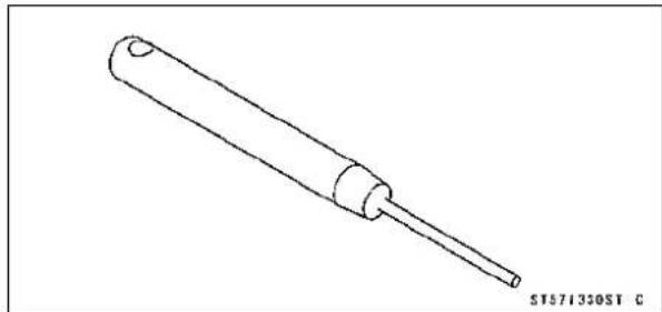
natural_image
Line drawing of a cylindrical mechanical component with a pointed tip and a base (no text or symbols)ValveGuideArbor,4.5: 57001-1331

natural_image
Technical line drawing of a mechanical component with a cylindrical shaft and flanged end (no text or symbols)ValveGuideReamer,4.5: 57001-1333

natural_image
Line drawing of a mechanical tool or rod with a flanged end (no text or symbols)PistonPinPuller: 57001-1568

natural_image
Technical line drawing of a mechanical device with cutaway view and two small components (no text or symbols)PistonPinPullerAdapterC: 57001-1657

natural_image
Technical line drawing of a mechanical connector (no text or symbols)KawasakiBond(SiliconeSealant): 92104-0004

CleanAirSystem
AirSuctionValveRemoval
- Remove:
FuelTank(seeFuelTankRemovalintheFuelSystem (DFI)chapter)
AirCleanerHousing(seeAirCleanerHousingRemoval intheFuelSystem(DFI)chapter)
AirSwitchingValvewithHoses(seeAirSwitchingValve Removal)
AirSuctionValveCoverBolts[A]andClamp
AirSuctionValveCover[B]
AirSuctionValve[C]
AirSuctionValveInstallation
- Installtheairsuctionvalve[A]sothatitssidewherestopperisfixedwiththescrews[B]facesthefront[C].
- Tighten:
Torque-AirSuctionValveCoverBolts:9.8N·m(1.0kgf·m, 87in·lb)


AirSuctionValveInspection
- Removetheairsuctionvalve(seeAirSuctionValveRemoval).
- Visually inspect thereeds for cracks, folds, warps, heat damage or other damage.
★ If thereisanydoubtastotheconditionofthereeds[A], replacetheairsuctionvalveasanassembly. - Checkthereedcontactareas[B]ofthevalveholderfor grooves,scratches,anysignsofseparationfromthe holderorheatdamage.
- Ifthereisanydoubtastotheconditionofthereedcontact areas,replaceheairsuctionvalveasanassembly.
- Ifanycarbonorotherforeignparticles have accumulated between thereed and thereed contact area, wash the valve assembly clean with a high-flash pointsolvent.

CAUTION
Donotscrapeoffthedepositswithascpraperasthis coulddamagetherubber,requiringreplacementof thesuctionvalveassembly.
AirSwitchingValveRemoval
- Remove:
FuelTank(seeFuelTankRemovalintheFuelSystem (DFI)chapter)
AirSwitchingValveConnectorA VacuumSwitchValve[B]

CleanAirSystem
AirSwitching Valve Installation
- Installthevacuumswitchvalvesothatthevacuumfitting [A]facesleftside.
- Routethehosescorrectly(seeCable, Wire, and Hose RoutingsectionintheAppendixchapter).
AirSwitching ValveOperationTest
- RefertoAirSwitchingValveOperationTestintheElectricalSystemchapter.
AirSwitchingValveUnitTest
- RefertoAirSwitchingValveUnitTestintheElectricalSystemchapter.
CleanAirSystemHoseInspection
- Becertainthatallthehosesareroutedwithoutbeingflattenedorkinked,andareconnectedcorrectlytotheair cleanerhousing,airswitchingvalve,#1and#2throttle bodyholdersandairsuctionvalvecovers.
★Iftheyarenot,correctthem.Replaceethemiftheyare damaged.
CylinderHeadCover
CylinderHeadCoverRemoval
- Remove:
FuelTank(seeFuelTankRemovalintheFuelSystem (DFI)chapter)
AirCleanerHousing(seeAirCleanerHousingRemoval intheFuelSystem(DFI)chapter)
AirSuctionValveCover[A]withHose[B] StickCoils[C]
BafflePlate
CylinderHeadCoverBolts[D]
CylinderHeadCover[E]
CylinderHeadCoverInstallation
- Replacetheheadcovergasket[A]withanewone.
- Applysiliconesealant[B]tothecylinderheadasshown.
Sealant-KawasakiBond(SiliconeSealant):92104-0004
• Install:
DowelPins[C]
PlugHoleGaskets[D]


- Install:
Washers[A]
CylinderHeadCoverBolts[B]
○Installthewasherswithmetalside[C]facesupward.
- Tighten:
Torque-CylinderHeadCoverBolts:9.8N·m(1.0kgf·m,87in·lb)

- Installthebaffleplate[A].
- Puttheinsulators[B]underthebaffleplateandthewashers[C]onthebaffleplate.
○Applyanon-permanentlockingagenttothebaffleplate boltsandtorquethem.
Torque-BafflePlateBolts:5.9N·m(0.60kgf·m,52in·lb)

CamshaftChainTensionerRemoval
CAUTION
Thisisanon-returntypecamshaftchaintensioner. Thepushroddoesnotreturntoitsoriginalposition onceitmovesouttotakeupcamshaftchainslack. Observealltheruleslistedbelow:
Whenremovingthetensioner, donottakeoutthe mountingboltsonlyhalfway. Retighteningthe mountingboltsfromthispositioncoulddamage thetensionerandthecamshaftchain. Oncethe boltsareloosened, thetensionermustberemoved andresetasdescribedin "CamshaftChainTensionerInstallation."
Donotturnoverthecrankshaftwhilethetensioner isremoved. Thiscouldupsetthecamshaftchain timing, anddamagethevalves.
- Remove:
CapBolt[A]
Washer [B]
Spring[C]
- Removethemountingbolts[D]andtakeoffthecamshaft chaintensioner.
CamshaftChainTensionerInstallation
- Releasethestopper[A]andpushthepushrod[B]into thetensioner[C].
- Installthetensionersothatthestopperfacesupward.
- Tightenthetensionermountingbolts[A].
Torque-CamshaftChainTensionerMountingBolts: 9.8 N·m(1.0kgf·m,87in·lb)
• Installthespringandwasher.
- Tightenthecapbolt[B].
Torque-CamshaftChainTensionerCapBolt:20N·m(2.0 kgf·m,15ft·lb)
- Turnthecrankshaft2turnsclockwisetoallowthetensionertoexpandandrecheckthecamshaftchaintiming.
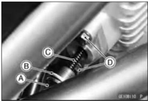


Camshaft,CamshaftChain
CamshaftRemoval
- Remove:
CylinderHeadCover(see CylinderHeadCoverRemoval) - Positionthecrankshaftasfollows.
○Removetheupper[A]andlower[B]capsontheclutch cover.
○Usingawrenchonthecrankshaftrotationbolt,turnthe crankshaftclockwiseuntilthe2|Tmarkline[A]onthetimingrotorisalignedwiththenotch[B]intheedgeofthe upperhole[C]intheclutchcover.


- Remove:
CamshaftChainTensioner(seeCamshaftChainTensionerRemoval)
CamshaftCapBolts[A]
CamshaftCaps[B]
Camshafts[C]

CAUTION
Thecrankshaftmaybeturnedwhilethecamshafts areremoved.Alwayspullthechaintautwhileturningthecrankshaft.Thisavoidskinkingthechain onthelower(crankshaft)sprocket.Akinkedchain coulddamageboththechainandthesprocket.
CamshaftInstallation
- Besuretoinstallthefollowingparts.
PlugHoleGaskets[A]
DowelPins[B]
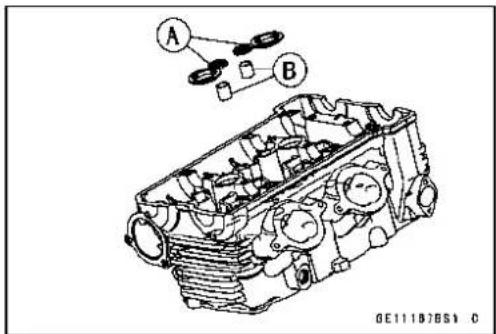
Camshaft, CamshaftChain
- Applymolybdenumdisulfideoilsolutiontoallcams[A] journals[B]andthrustblocks[C]with×marks.
- Ifanewcamshaftistobeused, applyathincoatofmolybdenumdisulfidegreasetothecamsurfaces.
NOTE
○ Theexhaustcamshafthasa2412EXmark[D]andthe inletcamshafthasa2412INmark[E].Becarefulnot tomixuptheseshafts.

GE11153BH2 C
- Positionthecrankshaftasfollows.
- Pullthetensionside(exhaustside)ofthechaintauto installthechain.
- Engagethecamshaftchainwiththecamshaftsprockets sothatthetimingmarksonthesprocketsarepositioned asshown.
○Usingawrenchonthecrankshaftrotationbolt,turnthe crankshaftclockwiseuntilthe2|Tmarkline[A]onthetimingrotorisalignedwiththenotch[B]intheedgeofthe upperhole[C]intheclutchcover.
- If the clutch covers removed, perform then next procedure.
○Usingawrenchonthecrankshaftrotationbolt,turnthe crankshaftclockwiseuntilthe1|Tmarkline[A]onthe timingrotorisalignedwiththewatingsurface[B]ofthe crankcasehalves.


Camshaft,CamshaftChain
OThetimingmarksmustbealignedwiththecylinderhead uppersurface[C]. EXmarkD INmarkE
1Pin[F]
2Pin[G]
31Pin[H]
32Pin[J]
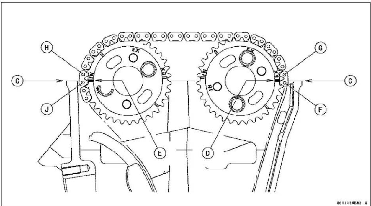
- Installthecamshaftcap, whilepushingthecamshaft chain, tightenallcamshaftboltsandchainguidebolts.
NOTE
○Theexhaustcaphasa“EX”mark[A]andtheinletcaphasa“IN”mark[B].Becarefulnottomixupthesecaps.
○Firsttightenallthecamshaftcapboltsevenlytoseatthe camshaftinplace, thentightenallboltsfollowingthespecifiedtighteningsequence.
Torque-CamshaftCapBolts(1\~12):12N·m(1.2kgf·m, 106in·lb)
- Install: CamshaftChainTensioner(seeCamshaftChainTensionerInstallation) CylinderHeadCover(seeCylinderHeadCoverInstallation)

Camshaft, CamshaftChain
CamshaftandSprocketAssembly
○Theinletandexhaustsprocketsareidentical.
- Installthesprocketssothatthemarked("IN"and"EX") sidefacestotherightside.
CAUTION
Inletsprocketmustuse“IN”markedboltsholes[A]. Exhaustsprocketmustuse“EX”markedbolts holes[B].
- Applyanon-permanentlockingagenttothecamshaft sprocketsboltsandtightenthem.
Torque-CamshaftSprocketsBolts:15N·m(1.5kgf·m,11ft·lb)
★Ifanewcamshaftistobeused,applyathincoatofa molybdenumdisulfidegreasetothecamsurfaces.
Camshaft, Camshaft Cap Wear
- Remove:
CamshaftCaps(seeCamshaftRemoval)
- Cutstripsofplastigagetojournalwidth.Placeastrip oneachjournalparalleltothecamshaftinstalledinthe correctposition.
- Measureeachclearancebetweenthecamshaftjournal andthecamshaftcapusingplastigage(pressgauge)[A].
- Tighten:
Torque-CamshaftCapBolts:12N·m(1.2kgf·m,106in·lb)
NOTE
○ Donotturnthecamshaftwhentheplastigageisbetweenthejournalandcamshaftcap.
CamshaftJournal, CamshaftCapClearance
Standard: 0.028 \~ 0.071 mm (0.0011 \~ 0.0028 in.) ServiceLimit:0.16mm(0.0063in.)
★Ifanyclearanceexceedstheservicelimit,measurethe diameterofeachcamshaftjournalwithamicrometer.
CamshaftJournalDiameter
Standard: 23.950 \~ 23.972 mm (0.9429 \~ 0.9438 in.) ServiceLimit: 23.92mm(0.942in.)
★Ifthecamshaftjournaldiameterislessthantheservice limit, replacethecamshaftwithanewoneandmeasure theclearanceagain.
★Iftheclearancestillremainsoutofthelimit,replace the cylinderheadunit.

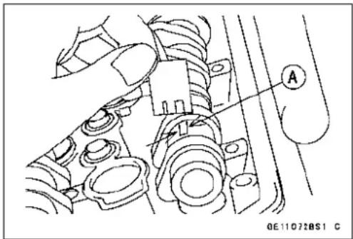
Camshaft,CamshaftChain
CamshaftRunout
- Removethecamshaft(seeCamshaftRemoval).
- SetthecamshaftinacamshaftalignmentjigoronV blocks.
- Measurerunoutwithadialgaugeatthespecifiedplace asshown.
★ Iftherunoutexceedstheservicelimit, replacetheshaft.
CamshaftRunout
Standard: TIR0.02mm(0.0008in.) or less
ServiceLimit:TIR0.1mm(0.004in.)

natural_image
Technical line drawing of a mechanical assembly with pressure gauge and mounting base (no text or symbols)CamWear
- Removethecamshaft(seeCamshaftRemoval).
- Measuretheheight[A]ofeachcamwithamicrometer.
★ Ifthecamsareworndownpasttheservicelimit,replace thecamshaft.
CamHeight
Standard:
Exhaust 35.843 \~ 35.957 mm (1.4111 \~ 1.4156 in.)
Inlet 36.543 \~ 36.657 mm (1.4387 \~ 1.4432 in.)
ServiceLimit:
Exhaust 35.74mm(1.4071in.)
Inlet 36.44mm(1.4346in.)
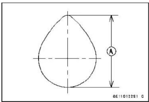
CamshaftChainRemoval
- Splitthecrankcase(seeCrankcaseSplittingintheCrankshaft/Transmissionchapter).
- Removethecamshaftchain[A]fromthecrankshaft sprocket.

natural_image
Mechanical assembly diagram showing gears and shafts in a vehicle (no text or symbols visible)CylinderCompressionMeasurement
NOTE
○ Usethebatterywhichisfullycharged.
● Warmuptheenginethoroughly.
- Stoptheengine.
- Remove:
Seat(seeSeatRemovalintheFramechapter)
FuelTank(seeFuelTankRemovalintheFuelSystem (DFI)chapter)
AirCleanerHousing(seeAirCleanerHousingRemoval intheFuelSystem(DFI)chapter)
StickCoils(seeStickCoil(IgnitionCoiltogetherwith SparkPlugCap)RemovalintheElectricalSystemchapter)
SparkPlugs(seeSparkPlugReplacementinthePeriodicMaintenancechapter)
Owner's Tool-SparkPlugWrench, 16mm:92110-1132
NOTE
○ Reconnecttheconnectorsoftheairswitchingvalve leadandtheinletairtemperaturesensorlead. When theignitionswitchisturnedONwiththeaboveconnec-torsdisconnected,theservicecodes(13,64)arestores intheECU.
- Attachthecompressiongauge[A]andadapter[B]firmly intothesparkplughole.
○Usingthestartermotor,turntheengineoverwiththethrottlefullyopenuntilthecompressiongaugestopsrising;the compressionisthehighestreadingobtainable.
SpecialTools-Compression Gauge,20 kgf/cm²:57001-221
CompressionGaugeAdapter, M10×1.0:
57001-1317
CylinderCompression
UsableRange: 961 \~ 1 471 kPa (9.8 \~ 15.0 kgf/cm², 139
\~ 213psi)@400r/min(rpm)
- Repeatthemeasurementfortheothercylinders.
• Installthesparkplugs.
Torque-SparkPlugs:15N·m(1.5kgf·m,11ft·lb)

CylinderHead
The following tables should be consulted if the obtainable compression reading is not within the usability range.
| ProblemDiagnosis | sisRemedy(Action) | |
| Cylindercompression ishigherthanusable range | Carbonaccumulationonpistonandin combustionchamberpossiblydueto damagedvalvestemoilsealand/or damagedpistonoilrings(Thismaybe indicatedbywhiteexhaustsmoke). | Removethecarbondeposits andreplacedamagedpartsif necessary. |
| Incorrectcylinderheadgasket thickness | Replacethegasketwithastandard part. | |
| Cylindercompression islowerthanusable range | Gasleakagearoundcylinderhead | Replacedamagedgasketand checkcylinderheadwarp. |
| BadconditionofvalveseatingRepairifnecessary. | ||
| IncorrectvalveclearanceAdjustthevalveclearance. | ||
| Incorrectpiston/cylinderclearanceReplace thepistonand/orcylinder. | ||
| Pistonseizure | Inspectthecylinderand replace/repairthecylinderand/or pistonasnecessary. | |
| Badconditionofpistonringand/or pistonringgrooves | Replacethepistonand/orthe pistonrings. | |
CylinderHeadRemoval
- Remove:
ExhaustPipes(seeExhaustPipeRemoval)
CylinderHeadCover(see CylinderHead Cover Removal)
Camshafts(seeCamshaftRemoval)
ThrottleBodyAssy(see ThrottleBodyAssyRemovalin theFuelSystem(DFI)chapter)
ThrottleBodyHolder
Water Hose
WaterTemperatureSensorConnector[A]
FrontCamshaftChainGuide
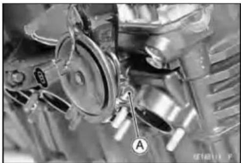
natural_image
Close-up of mechanical components with labeled parts (A) and no visible text or symbols5-22ENGINETOPEND
CylinderHead
- FirstlyremovetheM6cylinderheadboltsandM6cylinder bolts[A].
- Secondly,removetheM8bolts[B].
- Thirdly,removetheM10nut[C].
- Fourthly,removetheM10bolts[D].


CylinderHeadInstallation
NOTE
○ Thecamshaftcapismachinedwiththecylinderhead, soifanewcylinderheadisinstalled,usethecapthat issuppliedwiththenewhead.
- Installanewcylinderheadgasket[A]anddowelpins[B].

CylinderHead
- Applymolybdenumdisulfideoilsolution[A]tobothsides ofwashersandthethreadsofboltsandnut.
M10CylinderHeadBolts[B]
M10CylinderNut[C]
M8CylinderBolt[D]
- Torquethealltheboltsandnutfollowingthetightening sequence[1\~8].
Torque-CylinderHeadBolts(M10):
First:25N·m(2.5kgf·m,18ft·lb)
Final:
UsedBolts49N·m(5.0kgf·m,36ft·lb)
NewBolts54N·m(5.5 k g f · m, 40 ft · lb)
CylinderNut(M10):49N·m(5.0kgf·m,36ft·lb)
CylinderBolt(M8):27.5N·m(2.8kgf·m,20ft·lb)
NOTE
○ThetighteningsequenceNo.1 \~ No.5arethecylinder headboltsthataretightenedbetweenthecylinderhead withthecrankcase.
○TheNo.6isthecylinderheadboltthatistightenedbetweenthecylinderheadwiththecylinder.
○TheNo.7andNo.8arethecylindernutandcylinder boltthataretightenedbetweenthecylinderandthe crankcase.

5-24ENGINETOPEND
CylinderHead
- TightentheM6cylinderheadboltsandM6cylinderbolts [A].
Torque-CylinderHeadBolts(M6):12N·m(1.2kgf·m,106 in·lb)
CylinderBolts(M6):12N·m(1.2kgf·m,106in·lb)
• Installthefrontcamshaftchainguide[A].
○Inserttheend[B]offrontcamshaftchainguideintothe hollowonthelowercrankcasehalf.
- Installtheremovedparts(seeappropriatechapters).
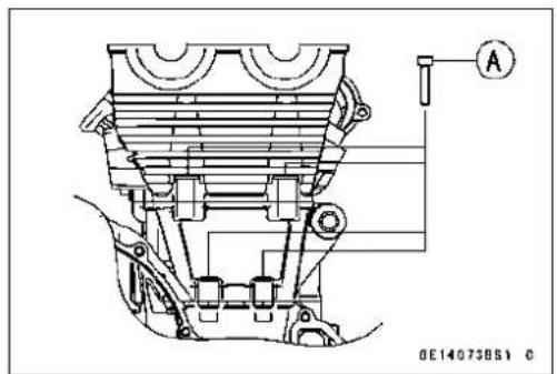

CylinderHeadWarp
- Cleanthecylinderhead.
- Layastraightedgeacrossthelowersurfaceofthecylinder headatseveralpositions.
- Useathicknessgauge[A]tomeasurethespacebetween thestraightedge[B]andthehead.
CylinderHeadWarp
Standard: ---
ServiceLimit:0.05mm(0.002in.)
★Ifthecylinderheadiswarpedmorethantheservicelimit, replaceit.
★Ifthecylinderheadiswarpedlessthantheservicelimit, repairtheheadbyrubbingthelowersurfaceonemery papersecuredtoasurfaceplate(firstNo.200,thenNo.400).

Valves
ValveClearanceInspection
- RefertoValveClearanceInspectioninthePeriodicMaintenancechapter.
ValveClearanceAdjustment
- RefertoValveClearanceAdjustmentinthePeriodic Maintenancechapter.
ValveRemoval
- Removecylinderhead(seeCylinderHeadRemoval).
- Removethevalvelifterandshim.
○Markandrecordthevalvelifterandshimlocationssothey canbeinstalledintheiroriginalpositions.
- Using the valvespringcompressorassembly, remove the valve.
SpecialTools-ValveSpringCompressorAssembly:57001-241[A]
ValveSpringCompressorAdapter, 21: 57001-1272[B]

ValveInstallation
- Replacetheoilsealwithanewone.
○Applyengineoiltotheoilseallip.
- Applyathincoatofmolybdenumdisulfidegreasetothe valvestembeforevalveinstallation.
- Installthespringssothattheclosedcoilendfacesdownwards(thesidepaintedingreenfacesupwards).
ValveStem[A]
OilSeal[B]
SpringSeat[C]
ClosedCoilEnd[D]
ValveSpring[E]
SidePaintedinGreen[F]
Retainer[G]
SplitKeepers[H]

Valve Guide Removal
- Remove:
Valve(seeValveRemoval)
OilSeal
SpringSeat
- Heattheareaaroundthevalveguideto120\~ 150°C(248
\~ 302°F), and hammer lightly on the valve guide arbor [A] to remove the guide from the top of the head.
CAUTION
Donotheatthecylinderheadwithatorch. This will warp the cylinderhead. Soakthecylinderhead in oil and heat the oil.
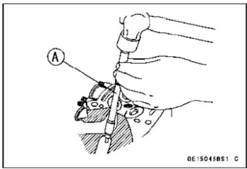
Special Tool - Valve Guide Arbor, 4.5 : 57001-1331
Valves
ValveGuideInstallation
- Applyoiltothevalveguideoutersurfacebeforeinstallation.
- Heattheareaaroundthevalveguideholetoabout120\~150°C(248\~302°F).
- Drivethevalveguideinfromthetopoftheheadusingthe valveguidearbor. Theflangestopstheguidefromgoing intoofar.
SpecialTool-ValveGuideArbor,4.5:57001-1331
- Waituntilthecylinderheadcoolsdownandthenreamthe valveguidewiththevalveguidereamer[A]eveniftheold guideisreused.
○Turnthereamerinaclockwisedirectionuntilthereamer turnsfreelyintheguide.Neverturnthereamercounter-clockwiseoritwillbedulled.
○Oncetheguidesarereamedtheymustbecleanedthoroughly.
SpecialTool-ValveGuideReamer,4.5:57001-1333
Valve-to-GuideClearanceMeasurement(Wobble Method)
Ifasmallboregaugeisnotavailable,inspectthevalve guidewearbymeasuringthevalvetovalveguideclearance withthewobblemethodasindicatedbelow.
- Insertanewvalve[A]intotheguide[B]andsetadial gaugeagainstthestemperpendiculartoitascloseas possibletothecylinderheadmatingsurface.
- Movethestembackandforth[C]tomeasurevalve/valve guideclearance.
- Repeatthemeasurementinadirectionatarightangleto thefirst.
★ Ifthereadingexceedstheservicelimit, replacetheguide.


NOTE
○ Thereadingisnotactualvalve/valveguideclearance becausethemeasuringpointisabovetheguide.
Valve/ValveGuideClearance(WobbleMethod)
Standard:
Exhaust 0.07 \~ 0.14 mm (0.0028 \~ 0.0055 in.)
Inlet 0.02 \~ 0.08 mm (0.0008 \~ 0.0032 in.)
ServiceLimit:
Exhaust 0.27mm(0.0106in.)
Inlet 0.22mm(0.0087in.)
Valves
ValveSeatInspection
- Removethevalve(seeValveRemoval).
- Checkthevalveseatingsurface[A]betweenthevalve[B] andvalveseat[C].
○Measuretheoutsidediameter[D]oftheseatingpattern onthevalveseat.
★ Iftheoutsidediameteristoolargeortoosmall, repair the seat(seeValveSeatRepair).
ValveSeatingSurfaceOutsideDiameter
Standard:
Exhaust 27.6 \~ 27.8 mm (1.087 \~ 1.094 in.)
Inlet 32.6 \~ 32.8 mm (1.283 \~ 1.291 in.)
○Measuretheseatwidth[E]oftheportionwherethereis nobuild-upcarbon(whiteportion)ofthevalveseatwitha verniercaliper. Good[F]
★ Ifthewidthistoowide[G], toonarrow[H]oruneven[J], repairtheseat(seeValveSeatRepair).
ValveSeatingSurfaceWidth
Standard:
Exhaust 0.5 \~ 1.0 mm (0.020 \~ 0.039 in.)
Inlet 0.5 \~ 1.0 mm (0.020 \~ 0.039 in.)

ValveSeatRepair
- Repairthevalveseatwiththevalveseatcutters[A]. SpecialTools-ValveSeatCutterHolderBar:57001-1128[C] ValveSeatCutterHolder, 4.5:57001 - 1330[B]
ForExhaustValveSeat
ValveSeatCutter,45°- φ30:57001-1187
ValveSeatCutter,32°- φ30:57001-1120
ValveSeatCutter,60°- φ30:57001-1123
ForInletValveSeat
ValveSeatCutter,45°- φ35:57001-1116
ValveSeatCutter,32°- φ35:57001-1121
ValveSeatCutter,55°- φ35:57001-1247
★ Ifthemanufacturer's instructions are not available, use the following procedure.
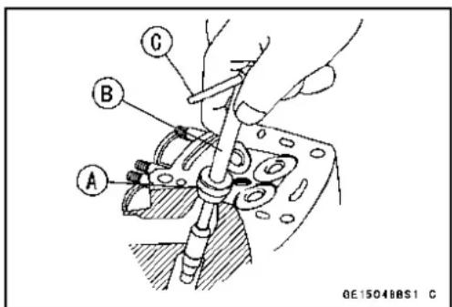
Valves
SeatCutterOperationCare
- This valveseatcutterisdeveloped to grind the valve for repair. Therefore the cutterm must not be used for other purpose sthan seat repair.
- Donotdroporshockthevalveseatcutter, orthedia-mondparticles may falloff.
- Donotfailtoapplyengineoiltothevalveseatcutter beforegrindingtheseatsurface. Alsowashoffground particlesstickingtothecutterwithwashingoil.
NOTE
○ Donotuseawirebrushtoremovethemetalparticles fromthecutter.Itwilltakeoffthediamondparticles.
- Setting the valveseat cutterholderinposition, operate the cutterinonehand. Donot apply to much force to the diamond portion.
NOTE
○ Priorogrinding, apply engine oil to the cutter and during the operation, wash off any ground particles sticking to the cutter with washing oil.
- After use, washit with washing oil and apply thin layer of engine oil before storing.
MarksStampedontheCutter
Themarksstampedonthebackofthecutter[A]represent the following.
60°....Cutterangle[B]
37.5 ......Outerdiameterofcutter[C]

OperatingProcedures
- Cleantheseatareacarefully.
- Coattheseatwithmachinist'sdye.
- Fita45°cutterintotheholderandslideitintothevalve guide.
- Pressdownlightlyonthehandleandturnitrightorleft. Grindtheseatingsurfaceonlyuntilissmooth.
CAUTION
Donotgrindtheseattoomuch. Overgrindingwill reducevalveclearancebysinkingthevalveintothe head.Ifthevalvesinkstoofarintothehead,itwill beimpossibletoadjusttheclearance,andthecylinderheadmustbereplaced.
Valves
- Measuretheoutsidediameteroftheseatingsurfacewithaverniercaliper.
★ Iftheoutsidediameteroftheseatingsurfaceistoosmall, repeatthe45°grinduntilthediameteriswithinthespecifiedrange.
WidenedWidth[A]ofengagementbymachiningwith 45°cutter
GroundVolume[B]by32°cutter 32°[C]
CorrectWidth[D]
GroundVolume[E]by60°or55°cutter
60°or55°[F]
- Measuretheoutsidediameteroftheseatingsurfacewithaverniercaliper.
★ Iftheoutsidediameteroftheseatingsurfaceistoosmall, repeatthe45°grind[A]untilthediameteriswithinthe specifiedrange.
OriginalSeatingSurface[B]
NOTE
○Removeallpittingsofflawsfrom45°groundsurface.
○Aftergrindingwith45°cutter,applythincoatofmachinist'sdyetoseatingsurface. Thismakesseatingsurface distinctand32°and60°(or55°)grindingoperationeasier.
○ Whenthevalveguideisreplaced, besuretogrindwith 45°cutterforcenteringandgoodcontact.
★ Iftheoutsidediameter[A]oftheseatingsurfaceistoo large, makethe32°grinddescribedbelow.
★ If the outsided diameter of these seating surface is within the specified range, measure these seat width as described below.
- Grindtheseatata32°angle[B]untiltheseatoutside diameteriswithinthespecifiedrange.
OTomakethe32°grind, fita32°cutterintotheholder, and slideitintothevalveguide.
○Turntheholderoneturnatatimewhilepressingdown verylightly.Checktheseataftereachturn.
CAUTION
The32°cutterremovesmaterialveryquickly. Checktheseatoutsidediameterfrequentlytoppreventovergrinding.
○Aftermakingthe32°grind, return to theseatoutsidediametermeasurementstepabove.
- Tomeasuretheseatwidth, useaverniercalipertomea-
surethewidthofthe45°angleportionoftheseatatseveralplacesaroundtheseat.
★ If theseatwidthistoonarrow, repeat the 45° grind until theseatisslightly toowide, and then return to theseat outsidediameter measurement step above.


Valves
★Iftheseatwidthhistoowide,makethe60°or55°[A]grind describedbelow.
★Iftheseatwidthiswithinthespecifiedrange,lapthevalve totheseatasdescribedbelow.
- Grindtheseatata60°or55°angleuntiltheseatwidthis withinthespecifiedrange.
- Tomakethe60°or55°grind, fit60°or55°cutterintothe holder, and slide it into the valve guide.
○Turntheholder,whilepressingdownlightly.
○Aftermakingthe60°or55°grind,returntotheseatwidth measurementstepabove.
CorrectWidth[B]
- Lapthevalvetotheseat, oncetheseatwidthandoutside diameterarewithintherangesspecifiedabove.
- Putalittlecoarsegrindingcompoundonthefaceofthe valveinanumberofplacesaroundthevalvehead.
○Spinthevalveagainsttheseatuntilthegrindingcompoundproducesasmooth, matchedsurfaceonboththe seatandthevalve.
○Repeat the process with a fine grinding compound.
Lapper[A] ValveSeat[B] Valve[C]
- Theseatingareashouldbemarkedaboutinthemiddle ofthevalveface.
★Iftheseatareaisnotintherightplaceonthevalve,check tobesurethevalveisthecorrectpart.Ifitis,itmayhave beenrefacedtoomuch;replaceit.
- Besuretoremoveallgrindingcompoundbeforeassembly.
- Whentheengineisassembled,besuretoadjustthevalve clearance(seeValveClearanceAdjustmentinthePeriodicMaintenancechapter).
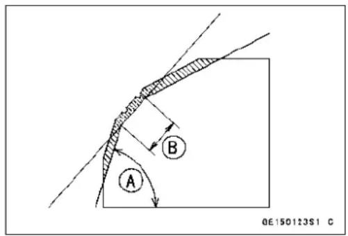
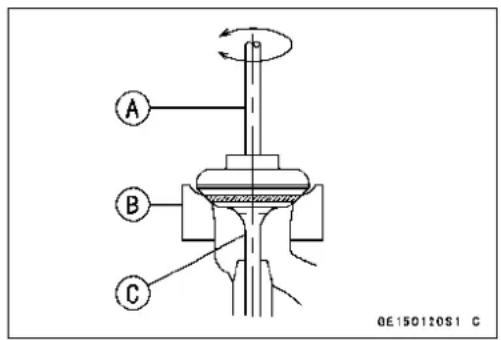
Valves

flowchart
graph TD
    A["START"] --> B["Machinist's dye on seat"]
    B --> C["45° Grind"]
    C --> D["Measure Seating Area O.D."]
    D --> E["Tools: Vernier Caliper\nPurpose: check seat O.D.\ngainst spec."]
    E --> F["Results"]
    F --> G["Too small"]
    G --> H["45° Grind\nTool: 45°Cutter\nPurpose: increase O.D. of\ncat area to spec."]
    F --> I["OK"]
    I --> J["Measure Seat Width\nTool: Vernier Caliper\nPurpose: check seat width\nagainst spec."]
    J --> K["Results"]
    K --> L["Too narrow"]
    L --> M["45° Grind\nTool: 45°Cutter\nPurpose: increase width of seat\nta area beyond spec.\nto increase O.D."]
    K --> N["OK"]
    N --> O["Too wide"]
    O --> P["Machinist's dye on seat"]
    P --> Q["60° or 55° Grind\nTool: 60°Cutter\nPurpose: reduce seat width\nto specification."]
    K --> R["Lap Valve\nTools: Valve Lapper,\nGrinding Compound\nPurpose: perfectly match valve\nand seat area; check\nvalve head for damage."]
    R --> S["FINISHED"]
5-32ENGINETOPEND
Cylinder, Pistons
CylinderRemoval
- Remove:
CylinderHead(see CylinderHeadRemoval) Horn
- Remove:
FrontEngineMountingBolts(BothSide)A FrontEngineBrackets(BothSide)B Cylinder[C]
CylinderInstallation
NOTE
○ Ifanewcylinderisused, usenewpistonring.
- Installthedowelpins[A]andnewcylindergasket[B].
- Thepistonringopeningsmustbepositionedasshownin thefigure. Theopeningsoftheoilringsteelrailsmustbe about30\~40°ofanglefromtheopeningofthetopring.
TopRing[A]
SecondRing[B]
OilRingSteelRails[C]
OilRingExpander[D]
Hollow[E]
30\~40°F
- Applymolybdenumdisulfideoilsolutiontothecylinder bore, pistonringsandpiston.
● Preparetwoauxiliaryheadboltswiththeirheadcut.
○Installthetwobolts[A]diagonallyinthecrankcase.
- Positionthecrankshaftsothatallthepistonheadsare almostlevel.
• Installthecylinderblock.
○Insertthepistonringswithyourthumbs.
PistonRemoval
- Removethecylinder(seeCylinderRemoval).
- Placeacleanclothunderthepistonsandremovethepistonpinsnapring[A]fromtheoutsideofeachpiston.


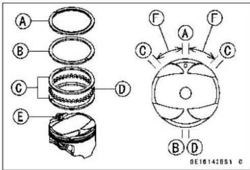

natural_image
Close-up mechanical assembly showing hoses and components (no visible text or symbols)
natural_image
Close-up of a mechanical component with labeled parts (A and B) and no readable text or symbols beyond labelsCylinder, Pistons
- Removethepistonpins.
SpecialTool-PistonPinPuller:57001-1568[A]
PistonPinPullerAdapterC:57001-1657[D]
CenterBolt[B]
ShallofPiston[C]
- Removethepistons.
- Carefullyspreadtheringopeningwithyourthumbsand thenpushupontheoppositesideofthering[A]toremove it.
- Removethe3-pieceoilringwithyourthumbsinthesame manner.
PistonInstallation
- Installtheoilringexpander[A]inthebottompistonring groovesotheends[B]butttogether.
- Installtheoilringsteelrails,oneabovetheexpanderand onebelowit.
○Spreadtherailwithyourthumbs,butonlyenoughtofit therailoverthepiston.
○Releasetherailintothebottompistonringgroove.
NOTE
○Theoilringrailshaveno "top" or "bottom".
- Donotmixupthetopandsecondring.
- Installthetopring[A]sothatthe"R"mark[B]facesup.
- Installthesecondring[C]sothatthe"RN"mark[D]faces up.


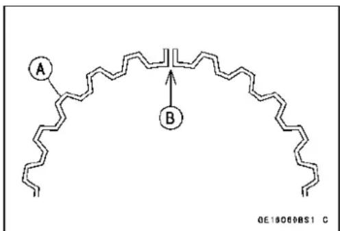
chemical
Chemical structure diagram showing a polymer chain with labeled points A and B, likely representing a polymer or functional group.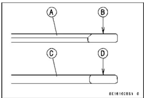
Cylinder, Pistons
NOTE
○ Ifanewpistonisused, usenewpistonring.
• Install the piston with its marking hollow facing forward.
- Fitanewpistonpinsnapringintothesideofthepiston sothattheringopening[A]doesnotcoincidewiththeslit [B]ofthepistonpinhole.
○Applymolybdenumdisulfideoilsolutiontothepistonpins andpistonjournals.
When installing the piston pinsnapring, compressit only enough to install it and nomore.
CAUTION
Donotreusesnaprings,asremovalweakensand deformsthem.Theycouldfalloutandscorethe cylinderwall.
- Installthecylinder(see Cylinder Installation).
CylinderWear
- Sincethereisadifferenceincylinderwearindifferentdirections, takeaside-to-sideandafront-to-backmeasurementateachofthetwolocations(totaloffourmeasurements)showninthefigure.
★Ifanyofthecylinderinsidediametermeasurementsexceedstheservicelimit,replacethecylinder. 10mm(0.39in.)[A] 60mm(2.36in.)[B]
CylinderInsideDiameter
Standard: 82.994 \~ 83.006 mm (3.2675 \~ 3.2679 in.)
ServiceLimit:83.10mm(3.2716in.)
PistonWear
- Measuretheoutsidediameter[A]ofeachpiston18mm (0.7087in.)[B]upfromthebottomofthepistonataright angletothedirectionofthepistonpin.
★Ifthemeasurementisunderservicelimit, replacethepiston.
PistonDiameter
Standard: 82.969 \~ 82.984 mm (3.2665 \~ 3.2671 in.)
ServiceLimit:82.82mm(3.2606in.)
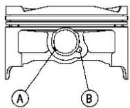
GE10144BS1 C

GE10145851 C

GE10146851 C
Cylinder, Pistons
PistonRing, PistonRingGrooveWear
- Checkforunevengroovewearbyinspectingtheringseating.
★Theringsshouldfitperfectlyparalleltogroovesurfaces. Ifnot, replacethepistonandallthepistonrings. - With the piston rings in their grooves, makes several measurements with a thickness gauge [A] to determine piston ring/groove clearance.
PistonRing/GrooveClearance
Top
Standard: 0.03 \~ 0.07 mm (0.0012 \~ 0.0028 in.)
ServiceLimit:0.17mm(0.0067in.)
Second
Standard: 0.02 \~ 0.06 mm (0.0008 \~ 0.0024 in.)
ServiceLimit:0.16mm(0.0063in.)

PistonRingGrooveWidth
- Measurethepistonringgroovewidth.
○Useaverniercaliperatseveralpointsaroundthepiston.
PistonRingGrooveWidth
Top[A]
Standard: 0.92 \~ 0.94 mm (0.0362 \~ 0.0370 in.)
ServiceLimit:1.02mm(0.040in.)
Second[B]
Standard: 1.01 \~ 1.03 mm (0.0398 \~ 0.0406 in.)
ServiceLimit:1.11mm(0.044in.)

★ If the width of any of the two grooves is wider than the servicelimitat anypoint, replacethepiston.
PistonRingThickness
● Measure the piston ring thickness.
○Usethemicrometertomeasureatseveralpointsaround thering.
PistonRingThickness
Top[A]
Standard: 0.87 \~ 0.89 mm (0.0342 \~ 0.0350 in.)
ServiceLimit: 0.80mm(0.031in.)
Second[B]
Standard: 0.97 \~ 0.99 mm (0.0382 \~ 0.0390 in.)
ServiceLimit: 0.90mm(0.035in.)

★ Ifanyofthemeasurementsislessthantheservicelimit oneitheroftherings,replacealltherings.
NOTE
○Whenusingnewringsinausedpiston,checkforunevengroovewear. Theringsshouldfitperfectlyparallel tothegroovesides. Ifnot,replacethepiston.
Cylinder, Pistons
PistonRingEndGap
- Placethepistonring[A]insidethecylinder,usingthepistontolocatetheringsquarelyinplace.Setitclosetothe bottomofthecylinder,wherecylinderwearislow.
- Measurethegap[B]betweentheendsoftheringwitha thicknessgauge.
PistonRingEndGap
Top
Standard: 0.25 \~ 0.40 mm (0.0098 \~ 0.0157 in.)
ServiceLimit:0.7mm(0.028in.)
Second
Standard: 0.40 \~ 0.55 mm (0.0157 \~ 0.0217 in.)
ServiceLimit:0.8mm(0.031in.)
★Iftheendgapofeitherringisgreaterthantheservice limit,replacealltherings.
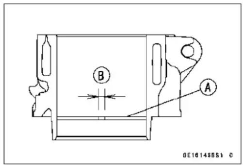
ThrottleBodyHolder
ThrottleBodyHolderInstallation
- BesuretoinstalltheO-rings[A].
- Installtheclamps[B]asshownandsothattheirprojec-tionsfit[C]ontheholesoftheholders.
○Besurethattheclampboltheads[D]faceoutwards.
- Tighten:
Torque-ThrottleBodyHolderBolts[E]:12N·m(1.2kgf·m, 106in·lb)
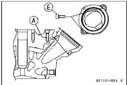
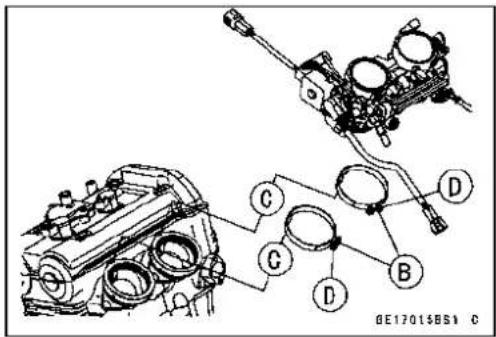
Muffler
A WARNING
Toavoidaseriousburn, donotremovethemuffler whentheengineisstillhot. Waituntilthemuffler cooldown.
MufflerBodyRemoval
- Remove:
RightFrameCover(seeFrameCoverRemovalinthe Framechapter)
- Removetheboltsandliftuptherightfootpegstay[A].
- Removethemufflerbodymountingbolts[A]andnut,and pullthemufflerbody[B]backward.
ExhaustPipeRemoval
- Remove:
LowerFairing(seeLowerFairingRemovalintheFrame chapter)
CenterFairing(seeCenterFairingRemovalinthe Framechapter)
MufflerBodyClampBolt[A]
ExhaustPipeManifoldHolderNuts[B]
ExhaustPipe[C]
Gaskets

natural_image
Mechanical assembly diagram showing a car chassis with labeled component A (no readable text or symbols)

Muffler
MufflerBodyandExhaustPipeInstallation
- Replacetheexhaustpipegaskets[A]andmufflerbody connectiongasket[B]withnewonesandinstallthem.
○Installthemufflerbodyconnectiongasketuntilitisbot-tomedsothatthechamferside[C]fecesmufflerbody[D].
- Install: MufflerBody ExhaustPipe[E]
- Tighten:
Torque-ExhaustPipeManifoldHolderNut[F]:17N·m(1.7 kgf·m,12ft·lb) MufflerBodyMountingBolts(FrontandRear)[G]: 20N·m(2.0kgf·m,15ft·lb)
- Tightenthemufflerbodyclampbolts[H].
○Installthemufflerbodyclampbolt[H]asshown.
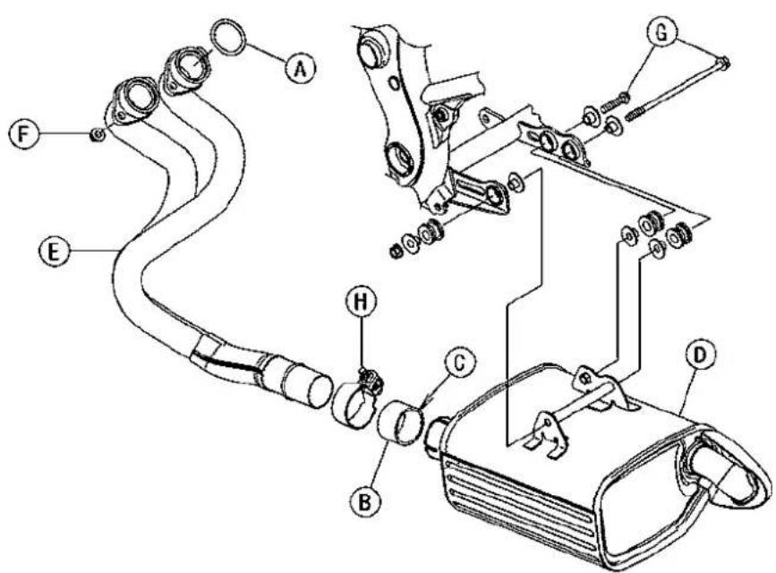
GE18024BH2 C
- Thoroughlywarmuptheengine, waituntiltheengine coolsdown, andretightenalltheboltsandnuts.
Clutch
TableofContents
Exploded View 6-2
Specifications 6-4
Special Tool and Sealant 6-5
Clutch Lever and Cable 6-6
Clutch Lever Free Play Inspection 6-6
ClutchLeverFreePlayAdjustment....6-6
Clutch Cable Removal 6-6
Clutch Cable Installation 6-6
Clutch Cable Lubrication.... 6-6
Clutch Lever Installation.... 6-7
Clutch Lever Adjustment.... 6-7
Clutch Cover 6-8
Clutch Cover Removal 6-8
Clutch Cover Installation 6-8
Release Shaft Removal 6-9
Release Shaft Installation 6-9
Clutch Cover Disassembly 6-9
Clutch Cover Assembly 6-10
Clutch 6-11
Clutch Removal.... 6-11
Clutch Installation.... 6-11
ClutchPlate,Wear,DamageInspection....6-13
Clutch Plate Warp Inspection.... 6-13
Clutch Spring Free Length Measurement 6-14
Clutch Housing Finger Inspection 6-14
Clutch Housing Spline Inspection 6-14

ExplodedView
| No.F | Fastener | Torque | Remarks | ||
| N·mkgf | ·mft·lb | ||||
| 1 | UpperCaponClutchCover3.90.4035in·lb | ||||
| 2 | LowerCaponClutchCover—Hard-tighten | ||||
| 3 | OilFillerPlug—Hard-tighten | ||||
| 4 | ClutchCoverMountingBolts | 9.8 | 1.0 | 87in·lb | |
| 5 | Clutch Spring Bolts | 9.8 | 1.0 | 87 in·lb | |
| 6 | Clutch Hub Nut | 132 | 13.5 | 98 | R |
| 7 | Oil Pump Sprocket Bolt | 12 | 1.2 | 106 in·lb | L, Lh |
| 8 | Clutch Lever Clamp Bolts | 7.8 | 0.80 | 69 in·lb | S |
| 9 | Oil Pump Chain Guide Bolts | 12 | 1.2 | 106 in·lb | L |
| 10 | ClutchCableHolderBolts | 9.8 | 1.0 | 87 in·lb | L |
| 11 | Clutch Cable Clamp Bolt | 9.8 | 1.0 | 87 in·lb | |
CL: Apply cable lubricant.
EO: Apply engine oil.
G: Apply grease.
HG: Applyhigh-temperature grease.
Lh: Left-hard Threads
M: Applymolybdenum disulfidegrease.
R: Replacement Parts
W: Applywater.
Specifications
| ItemStandardServiceLimit | ||
| Clutch Lever Free Play | 2 ~ 3 mm (0.08 ~ 0.12 in.) | -- -- |
| Clutch | ||
| Friction Plate Thickness | 2.92 ~ 3.08 mm (0.115 ~ 0.121 in.) | 2.8 mm (0.110 in.) |
| Friction Plate Warp | 0.15 mm (0.16 in.) or less | 0.3 mm (0.012 in.) |
| Steel Plate Warp | 0.2 mm (0.008 in.) or less | 0.3 mm (0.012 in.) |
| Clutch Spring Free Length | 33.6 mm (1.32 in.) | 32.6 mm (1.28 in.) |
SpecialToolandSealant
ClutchHolder: 57001-1243

natural_image
Technical line drawing of a mechanical clamp or bracket assembly (no text or symbols)KawasakiBond(SiliconeSealant): 92104-0004

ClutchLeverandCable
ClutchLeverFreePlayInspection
- RefertoClutchOperationInspectioninthePeriodicMaintenancechapter.
ClutchLeverFreePlayAdjustment
- RefertoClutchOperationInspectioninthePeriodicMaintenancechapter.
ClutchCableRemoval
- Removetherightframecover(seeFrameCoverRemoval intheFramechapter).
- Slidethedustcover[A]atthemiddleofclutchcableout ofplace.
- Loosenthelocknut[B], and turnthead adjusting nut[C] to givethecable plenty of play.
- Screwintheadjuster.
- Lineuptheslots[A]intheclutchleverandadjuster[B], and thenfreethecablefromthelever.
- Freetheclutchinnercabletipfromtheclutchrelease lever.
- Disconnecttheclutchcableclamp[A]onthecylinder headcover.
- Pulltheclutchcableoutoftheframe.
ClutchCableInstallation
- Runtheclutchcablecorrectly(seeCable, Wire, and Hose RoutingsectionintheAppendixchapter).
- Adjusttheclutchcable(seeClutchOperationInspection inthePeriodicMaintenancechapter).
ClutchCableLubrication
- RefertoChassisPartsLubricationinthePeriodicMaintenancechapter.


natural_image
Technical line drawing of a mechanical device with labeled component A (no text or symbols beyond label)ClutchLeverandCable
ClutchLeverInstallation
- Installtheclutchleversothatthematingsurface[B]ofthe clutchleverclampisalignedwiththepunchmark[A].
- Tightentheupperclampboltfirst, andthenthelower clampbolt. Therewillbeagapatthelowerpartofthe clampaftertightening.
Torque-ClutchLeverClampBolts:7.8N·m(0.80kgf·m,69in·lb)
ClutchLeverAdjustment
Theadjusterhas5positionssothattheclutchleverpositioncanbeadjustedtosuittheoperator'shand.
- Pushtheleverforwardandturntheadjuster[A]toalign thenumberwiththearrowmark[B]ontheleverholder.
○The distance from the griptotheleveris minimum at number 5 and maximum at number 1.


ClutchCover
ClutchCoverRemoval
- Remove:
EngineOil(drain,seeEngineOilChangeinthePeriodic Maintenancechapter) RightFrameCover(seeFrameCoverRemovalinthe Framechapter) ClutchCableLowerEnd[A] ClutchCoverMountingBolts[B]
- Turnthereleaselever[A]towardtherearasshown,and removetheclutchcover[B]. About90°[C]
- Pushthereleaselevertowardthefrontofthemotorcycle andtapethereleaselevertotheclutchcovertoprevent thereleaseshaftfromfallingout.
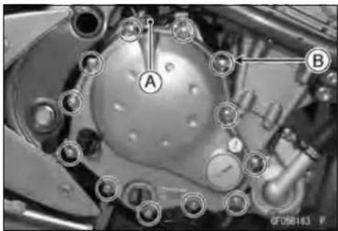
natural_image
Mechanical component diagram showing a central circular component with labeled points A and B, surrounded by mechanical parts (no readable text or symbols)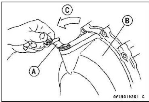
ClutchCoverInstallation
- Applysiliconesealanttothearea[A]wherethemating surfaceofthecrankcasetouchestheclutchcovergasket andtothecrankshaftsensorleadgrommet[B].
Sealant-KawasakiBond(SiliconeSealant):92104-0004
- Besurethatthedowelpins[C]areinposition.
- Replacetheclutchcovergasket[D]withanewone.
- Tightentheclutchcovermountingbolts.
Torque-ClutchCoverMountingBolts:9.8N·m(1.0kgf·m, 87in·lb)

ClutchCover
ReleaseShaftRemoval
CAUTION
Donotremovetheclutchreleaseleverandshaft assemblyunlessitisabsolutelynecessary.Ifremoved,theoilsealreplacementmayberequired.
- Removetheclutchcover(seeClutchCoverRemoval).
- Pulltheleverandshaftassemblystraightoutoftheclutch cover.
ReleaseShaftInstallation
- Applyhigh-temperaturegreasetotheoilseallipsonthe upperridgeoftheclutchcover.
- Applyengineoiltotheneedlebearingsintheholeofthe clutchcover.
- Applymolybdenumdisulfidegreasetothepusher-holding portion[A]onthereleaseshaft.
• Installthewasher[B]andspring[C]. - Insertthereleaseshaftstraightintotheupperholeofthe clutchcover.
CAUTION
Wheninsertingthereleaseshaft,becarefulnotto removethespringoftheoilseal.
- Fitthespring[A]asshown.
ReleaseShaft[B]
ClutchCover[C]


ClutchCoverDisassembly
- Remove:
OilSeal[A]
NeedleBearings[B]
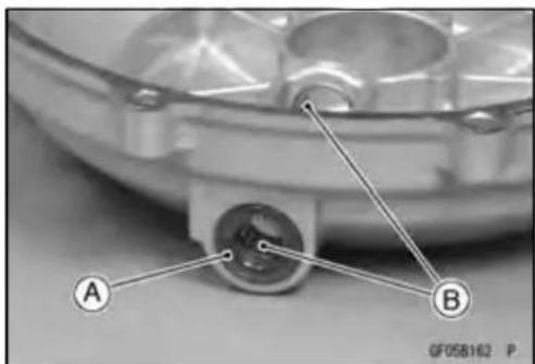
natural_image
Close-up of a mechanical component with labeled parts A and B, no readable text or symbols beyond labelsClutchCover
- Removetheoillevelgauge[A].
ClutchCoverAssembly
- Replacetheneedlebearingsandoilsealwithnewones.
NOTE
○ Installtheneedlebearingssothatthemanufacture's markfaceout.
- Installtheneedlebearings[A]andoilseal[B]positionas shown.
Press[C]thebearingsothathebearingsurface[D]is flushwiththehousingendofclutchcover[E].
- Applywatertotherubberoftheoilgauge[A]andpress [C]itsothatthering[B]faceoutside.


Clutch
ClutchRemoval
- Remove:
EngineOil(drain,seeEngineOilChangeinthePeriodic Maintenancechapter)
ClutchCover(seeClutchCoverRemoval)
ClutchSpringBolts[A]
ClutchSprings
ClutchSpringPlateB
- Remove:
FrictionPlates,SteelPlates ClutchHubNut[A]
○Holdingtheclutchhub[B],removethenutandwasher.
SpecialTool-ClutchHolder[C]:57001-1243
- Remove:
ClutchHub Spacer
- Removetheoilpumpsprocketboat[A].
NOTE
○Theoilpumpsprocketbolthasaleft-handthreads.
• Usingthehole[B], pulloutthesleeve[C].
- Removethefollowingasaset.
ClutchHousing[D] OilPumpChain[E] OilPumpSprocket[F]
- Unscrewthebolts[A]andremovetheoilpumpchain guide[B].
ClutchInstallation
- Applyanon-permanentlockingagenttotheoilpump chainguideboltsandtightenthem.
Torque-OilPumpChainGuideBolts:12N·m(1.2kgf·m, 106in·lb)
- Puttheoilpumpchain[A]ontheclutchhousinggear[B] andtheoilpumpsprocket[C].


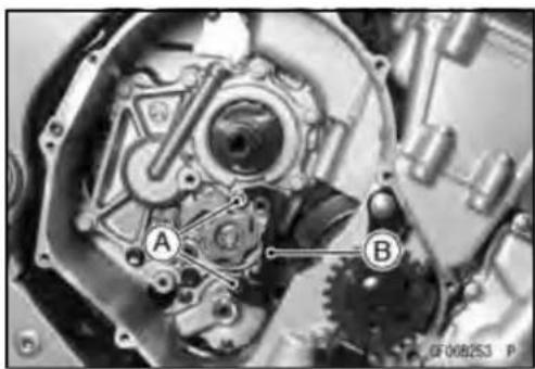
natural_image
Mechanical gear assembly diagram showing internal components labeled A and B (no text or symbols beyond labels)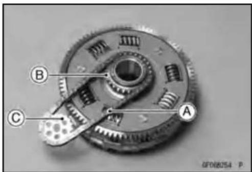
Clutch
- Besurethatthespacer[A]isinposition.
- Insertthefollowingonthedriveshaft. ClutchHousing[A]withChain[B]andSprocket[C] Sleeve[D]
- Align[E]theholeontheoilpumpsprocketwiththeoil pumpshaft.
- Installthefollowingpartsonthedriveshaft. Spacer[A] ClutchHub[B] Washer[C] Nut[D]
○InstallthewashersothattheOUTSIDEmark[A]faces outward.
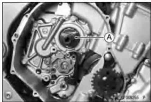
natural_image
Close-up mechanical assembly showing gears and a central component (no visible text or symbols)
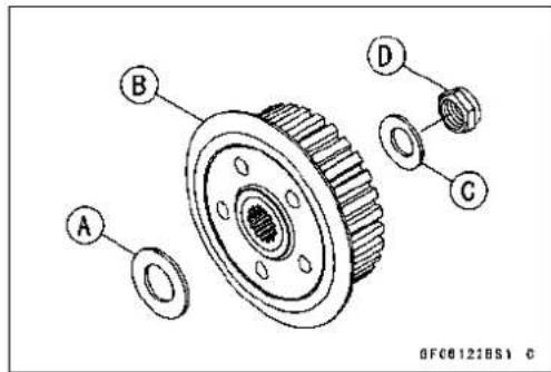
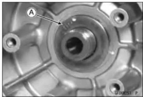
natural_image
Close-up of a mechanical component with labeled point A and reference number GF00851 P (no readable text or symbols beyond labels)- Replacetheclutchhubnutwithanewone. - Holdingtheclutchhub,tightentheclutchhubnut. SpecialTool-ClutchHolder:57001-1243 Torque-ClutchHubNut:132N·m(13.5kgf·m,98ft·lb)
Clutch
- Install the friction plates and steel plates, starting with a friction plate and alternating them.
CAUTION
If new dry friction plates and steel plates are installed, apply engine oil to the surfaces of each plateto avoid clutch plates seizure.
○Forthefirststeelplate[A],itsthicknessis2.6mm(0.10 in.).Theothersare2.3mm(0.09in.).
○Installthelastfrictionplate[A]fittingthetangsinthe groovesinthehousingasshown.

natural_image
Technical illustration of a mechanical gear assembly with labeled component A (no text or symbols beyond label)
- Applymolybdenumdisulfidegreasetothepusherends [A]andinstallitintheclutchspringplate[B].
○Applyengineoiltothebearing[C]. - Installtheclutchspringplateandsprings[D], andtighten theclutchspringbolts[E].
Torque-ClutchSpringBolts:9.8N·m(1.0kgf·m,87in·lb)
- Installtheclutchcover(seeClutchCoverInstallation).
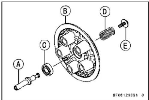

ClutchPlate, Wear, DamageInspection
- Visually inspect the friction and steel plates for sign of seizure, overheating (discoloration), or uneven wear.
- Measurethethicknessofeachfrictionplate[A]atseveral points.
★Ifanyplatesshowsignsofdamage,oriftheyhaveworn pasttheservicelimit,replacethemwithnewones.
FrictionPlateThickness
Standard: 2.92 \~ 3.08 mm (0.115 \~ 0.121 in.)
ServiceLimit:2.8mm(0.110in.)
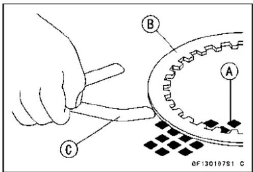
ClutchPlateWarpInspection
- Placeeachfrictionplateorsteelplateonasurfaceplate andmeasurethegapbetweenthesurfaceplate[A]and eachfrictionplateorsteelplate[B]withathicknessgauge [C].Thegapistheamountoffrictionorsteelplatearp.
★ Ifanyplateiswarpedovertheservicelimit, replaceitwith anewone.
FrictionandSteelPlateWarp
Standard:0.15mm(0.006in.)orless
ServiceLimit:0.3mm(0.012in.)
Clutch
ClutchSpringFreeLengthMeasurement
- Measurethefreelengthoftheclutchsprings[A].
★Ifanyspringisshorterthantheservicelimit, it must be replaced.
ClutchSpringFreeLength
Standard:33.6mm(1.32in.)
ServiceLimit:32.6mm(1.28in.)
ClutchHousingFingerInspection
- Visuallyinspecttheclutchhousingfingers[A]wherethe frictionplatetangs[B]hitthem.
★Iftheyarebadlywornoriftherearegroovecutswherethe tangshit,replacethehousing.Also,replacethefriction platesiftheirtangsaredamaged.
ClutchHousingSplineInspection
- Visuallyinspectwheretheteeth[B]onthesteelplates wearagainsttheclutchhubsplines[A].
★Iftherearenotcheswornintothesplines,replace the clutchhub.Also,replacethesteelplatesiftheirteethare damaged.
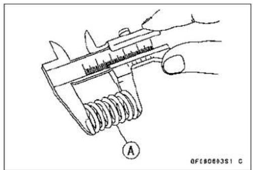


EngineLubricationSystem
TableofContents
Exploded View 7-2
Engine Oil Flow Chart.... 7-4
Specifications 7-6
Special Tools and Sealant 7-7
Engine Oil and Oil Filter 7-8
Oil Level Inspection.... 7-8
Engine Oil Change 7-8
Oil Filter Replacement 7-8
Oil Pan 7-9
Oil Pan Removal 7-9
Oil Pan Installation 7-10
Oil Pressure Relief Valve 7-11
Oil Pressure Relief Valve Removal 7-11
Oil Pressure Relief Valve Installation 7-11
Oil Pressure Relief Valve Inspection.... 7-11
Oil Pump 7-12
Oil Pump Removal 7-12
Oil Pump Installation 7-13
Oil Pressure Measurement.... 7-14
Oil Pressure Measurement 7-14
Oil Pressure Switch 7-15
Oil Pressure Switch Removal 7-15
Oil Pressure Switch Installation 7-15
ExplodedView

ExplodedView
| No.Fastener | Torque | Remarks | |||
| N·mkgf·mft·lb | |||||
| 1EngineOilDrainBolt202.015 | |||||
| 2FilterPlateBolts9.81.087in·lbL | |||||
| 3 | Oil Filter | 17.2 | 1.75 | 13 | EO, R |
| 4 | Holder Mounting Bolt | 25 | 2.5 | 18 | L |
| 5 | Oil Pan Bolts | 12 | 1.2 | 106 in·lb | |
| 6 | Oil Pipe Plate Bolt | 9.8 | 1.0 | 87 in·lb | L |
| 7 | Oil Pressure Relief Valve | 15 | 1.5 | 11 | L |
| 8 | Oil Pressure Switch | 15 | 1.5 | 11 | SS |
| 9 | Oil Pump Cover Bolts | 9.8 | 1.0 | 87 in·lb | L |
| 10 | OilPumpSprocketBolt | 12 | 1.2 | 106 in·lb | L, Lh |
| 11 | Oil Passage Plugs | 20 | 2.0 | 15 | L |
| 12 | Lower Fairing Bracket Bolts | 12 | 1.2 | 106 in·lb | L |
| 13 | OilPump ChainGuideBolts | 12 | 1.2 | 106 in·lb | L |
| 14 | Oil Plate Bolts | 9.8 | 1.0 | 87 in·lb | L |
EO: Applyengineoil.
G: Applygrease.
L: Applyanon-permanentlockingagent.
Lh: Left-hand-threads
MO: Apply molybdenum disulfide oil solution.
(mixture of the engine oil and molybdenum disulfide grease in a weight ratio 10 : 1)
R: ReplacementParts
SS: Apply silicone sealant (Kawasaki Bond: 56019-120).
7-4 ENGINE LUBRICATION SYSTEM
EngineOilFlowChart

EngineOilFlowChart
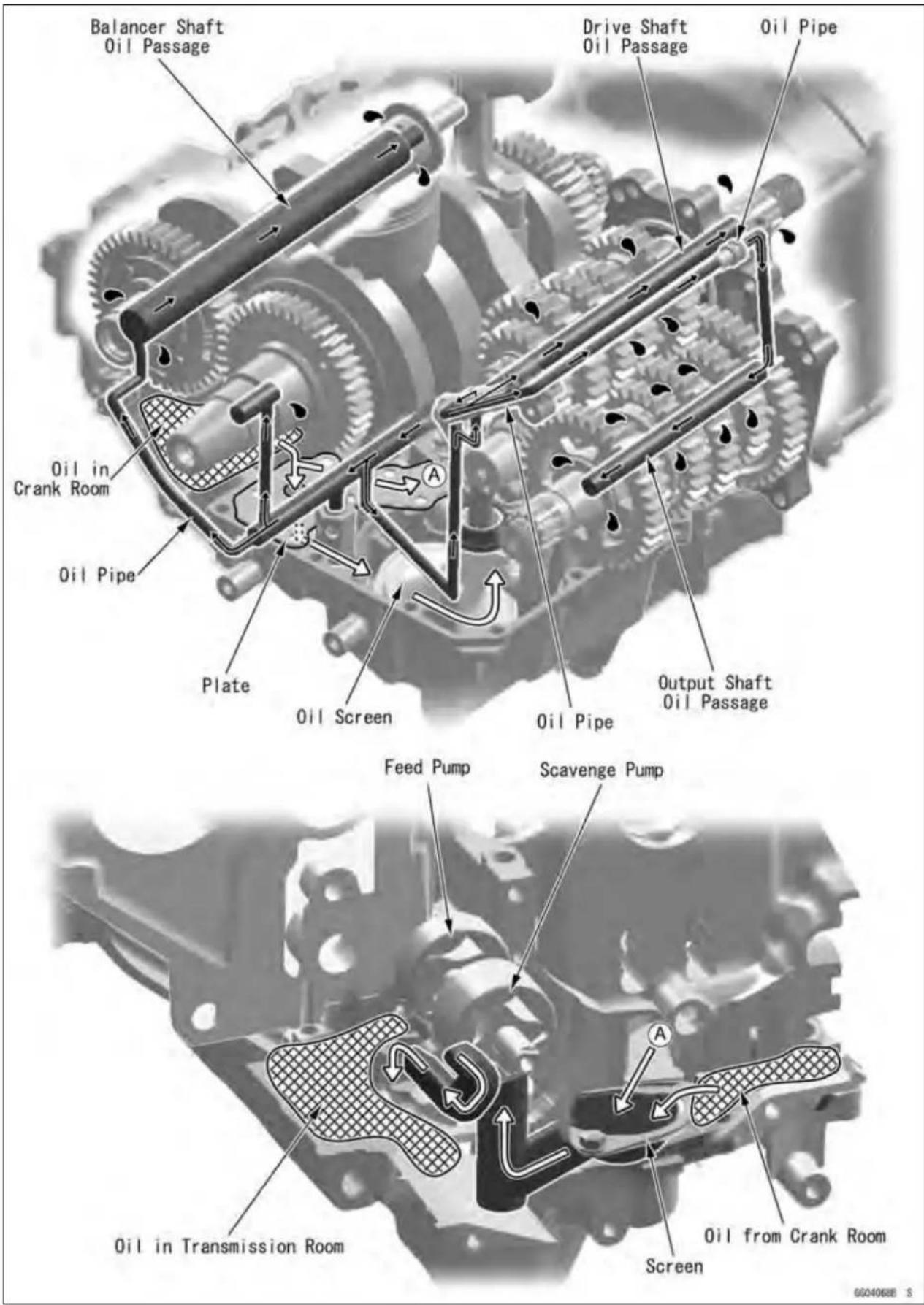
Specifications
| ItemStandard | |
| EngineOilTypeViscositySAE10W-40Capacity:1.7L(1.8USgt)(whenfilterisnotremoved)LevelBetweenupperandlower | APISE,SForSGAPISH,SJorSLwithJASOMA1.9L(2.0USgt)(whenfilterisremoved)2.4L(2.5USgt)(whenengineiscompletelydry)evellines |
| OilPressureMeasurementOil Pressure | 216 ~ 294 kPa (2.2 ~ 3.0 kgf/cm2, 31 ~ 43 psi) @4 000 r/min (rpm), OilTemperature90°C(194°F) |
SpecialToolsandSealant
OilPressureGauge,10kgf/cm²: 57001-164
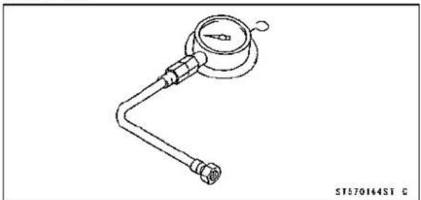
natural_image
Line drawing of a pressure gauge with a handle and connector (no text or symbols)OilPressureGaugeAdapter,PT3/8×19/in.: 57001-1233

natural_image
Technical line drawing of a mechanical connector (no text or symbols)OilFilterWrench: 57001-1249

natural_image
Technical line drawing of a mechanical component with hexagonal base and central nut (no text or symbols)KawasakiBond(SiliconeSealant): 56019-120
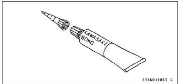
EngineOilandOilFilter
WARNING
Motorcycleoperationwithinsufficient,deteriorated,orcontaminatedengineoilwillcause acceleratedwearandmayresultinengineortransmissionseizure,accident,andinjury.
OilLevelInspection
- Check that the engine oil level is between the upper [A] and lower [B] levels in the gauge.
NOTE
○ Situatethemotorcyclesothatitisperpendiculartothe ground.
○ Ifthemotorcyclehasjustbeenused, waitseveralminutesforalltheoiltodraindown.
○ Iftheoilhasjustbeenchanged,starttheengineand runitforseveralminutesatidlespeed. Thisfillstheoil filterwithoil. Stoptheengine,thenwaitseveralminutes untiltheoilsettles.
CAUTION
Racingtheenginebeforetheoilreacheseverypart cancauseengineseizure. Iftheengineoilgetsextremelyloworiftheoilpump oroilpassagescloguporotherwisedonotfunction properly,theoilpressurewarninglightwilllight.If thislightstaysonwhentheengineisrunningabove idlespeed,stoptheengineimmediatelyandfindthe cause.
★Iftheoillevelistoohigh,removetheexcessoil,usinga syringorsomeothersuitabledevice.
★Iftheoillevelistoolow,addthecorrect amountofoil through the oil filter opening. Use the same type and makeofoilthatisalreadyintheengine.
NOTE
○ Iftheengineoiltypeandmakeareunknown,useany brandofthespecifiedoiltotopoffthelevelinpreference torunningtheenginewiththeoillevellow. Thenatyour earliestconvenience,changetheoilcompletely.
EngineOilChange
- RefertoEngineOilChangeinthePeriodicMaintenance chapter.
OilFilterReplacement
- Refer to Oil Filter Replacement in the Periodic Maintenancechapter.
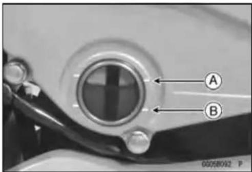
OilPan
OilPanRemoval
- Remove:
EngineOil(drain,seeEngineOilChangeinthePeriodic Maintenancechapter) ExhaustPipe(seeExhaustPipeRemovalintheEngine TopEndchapter) MufflerBody(seeMufflerBodyRemovalintheEngine TopEndchapter) OilPanBolts[A] OilPan[B] Gasket[C] Damper[D]

- Removethefollowingfromtheoilpanasnecessary. FilterPlateBolts[A] FilterPlate[B] Filter[C]

- Removethefollowingfromthelowercrankcasehalfas necessary. OilScreen[A] OilPipePlateBolt[B] OilPipePlate[C] OilPipes[D] OilPressureReliefValve[E]
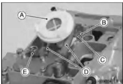
7-10ENGINELUBRICATIONSYSTEM
OilPan
OilPanInstallation
- ApplygreasetotheO-ringsontheoilpipes[A].
- Installtheoilpipeplate[B]sothatitsguideportion[C]fits thebreatherpipe[D]asshown.
- Applyanon-permanentlockingagenttotheoilpipeplate bolt.
Torque-OilPipePlateBolt[E]:9.8N·m(1.0kgf·m,87in·lb)
★Iftheoilpressurereliefvalve[F]wasremoved,installit.
○Applyanon-permanentlockingagenttothethreads[G] oftheoilpressurereliefvalve,andtightenit.
CAUTION
Donotapplytoomuchnon-permanentlocking agenttothethreads. This may block the oil passage.
Torque-OilPressureReliefValve:15N·m(1.5kgf·m,11ft·lb)
- ApplygreasetotheO-ring[A]ontheoilscreen[B]and installitonthelowercrankcasehalfasshown.
-
Besurethedamper[C]isontheendofthebreatherpipe [D].
-
Replacetheoilpangasketwithanewone.
- Wheninstallingtheoilpan, align[A]thedamper[B]on thebreatherpipewiththehollow[C]ontheoilpan.
- Tighten: Torque-OilPanBolts:12N·m(1.2kgf·m,106in·lb)


OilPressureReliefValve
OilPressureReliefValveRemoval
- SeeOilPanRemoval.
OilPressureReliefValveInstallation
- SeeOilPanInstallation.
OilPressureReliefValveInspection
- Checktoseeifthevalve[A]slidessmoothlywhenpushingitinwithawoodenorothersoftrod,andseeifitcomes backtoitsseatbyspring[B]pressure.
NOTE
○Inspectthevalveinitsassembledstate.Disassembly andassemblymaychangethevalveperformance.
★Ifanyroughspotsarefoundduringaboveinspection, washthevalvecleanwithahigh-flashpointsolventand blowoutanyforeignparticlesthatmaybeinthevalvewith compressedair.
WARNING
Cleantheoilpressurereliefvalveinawell -ventilatedarea,andtakecarethatthereisno sparkorflameanywhereneartheworkingarea. Becauseofthedangerofhighlyflammableliquids, donotusegasolineorlow-flashpointsolvent.
★If cleaning does not solve the problem, replace the oil pressure relief valve as an assembly. The oil pressure relief valve is precision made with no allowance for replacement of individual parts.

7-12ENGINELUBRICATIONSYSTEM
OilPump
OilPumpRemoval
- Drain:
EngineOil(seeEngineOilChangeinthePeriodicMaintenancechapter) - Remove:
Clutch(seeClutchRemovalintheClutchchapter) OilPumpCoverBolts[A] OilPumpCover[B]
- Remove:
InnerRotor[A]forScavengePump OuterRotor[B]forScavengePump
- Remove:
DowelPin[A]
Pin[B]
OilPumpBody[C]withOilPumpShaft[D]andPin
- Remove:
InnerRotor[A]forFeedPump
OuterRotor[B]forFeedPump


OilPump
OilPumpInstallation
- Applymolybdenumdisulfidegreasetotheportion[A]of theoilpumpshaft,asshown.
- Install: OuterRotor[B]forFeedPump InnerRotor[C]forFeedPump OilPumpShaft[D]andPin[E] DowelPin[F] OilPumpBody[G] Pin[H]andInnerRotor[I]forScavengePump OuterRotor[J]forScavengePump OilPumpCover[K]
NOTE
○ Thescavengepumprotorsarewiderthanthefeed pumprotors.
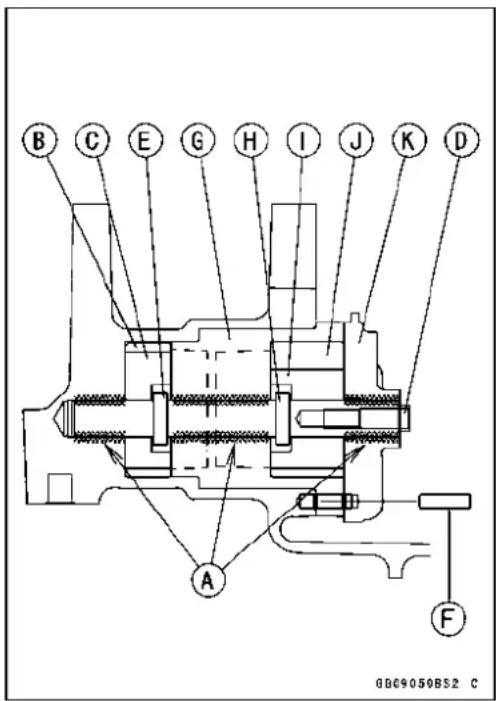
- Applyanon-permanentlockingagenttotheoilpump coverboltsandtightenthem. Torque-OilPumpCoverBolts:9.8N·m(1.0kgf·m,87in·lb)
7-14ENGINELUBRICATIONSYSTEM
OilPressureMeasurement
OilPressureMeasurement
- Removethelowerfairing(seeLowerFairingRemovalin theFramechapter).
- Removetheoilpassageplug, and attach the adapter[A] and gauge[B] to the plughole.
SpecialTools-OilPressureGauge,10kgf/cm²:57001-164 OilPressureGaugeAdapter,PT3/8×19/in.: 57001-1233

- Starttheengineandwarmuptheengine.
- Runtheengineatthespecifiedspeed,andreadtheoil pressuregauge.
★Iftheoilpressureismuchlowerthanthestandard,check theoilpump,reliefvalve,and/orcrankshaftbearinginsert wearimmediately.
★Ifthereadingismuchhigherthanthestandard,checkthe oilpassagesforclogging.
OilPressure
Standard: 216 \~ 294 kPa (2.2 \~ 3.0 kgf/cm², 31 \~ 43 psi)@4000r/min(rpm),oiltemperature. 90°C(194°F)
- Stoptheengine.
- Removetheoilpressuregaugeandadapter.
WARNING
Takecareagainstburnsformhotengineoilthat willdrainthroughtheoilpassagewhenthegauge adapterisremoved.
- Applyanon-permanentlockingagenttotheoilpassage plug, and installit.
Torque-OilPassagePlug(Right): 20N·m(2.0kgf·m,15ft·lb)
OilPressureSwitch
OilPressureSwitchRemoval
- Removeordrain:
EngineOil(seeEngineOilChangeinthePeriodicMaintenancechapter)
SwitchCover[A]
SwitchTerminalBolt[B]
OilPressureSwitch[C]

OilPressureSwitchInstallation
- Applysiliconesealanttothethreadsoftheoilpressure switchandtightenit.
Sealant-KawasakiBond(SiliconeSealant):56019-120
Torque-OilPressureSwitch:15N·m(1.5kgf·m,11ft·lb)
- Tightentheterminalboltsecurely.
- Applyasmallamountgreasetotheterminalsothat greaseshouldnotclosetheholes[A]oftheswitchcover.
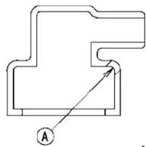
natural_image
Pure mechanical part diagram with no text, numbers, or symbolsEngineRemoval/Installation
TableofContents
Exploded View 8-2
Engine Removal/Installation 8-4
Engine Removal 8-4
ExplodedView
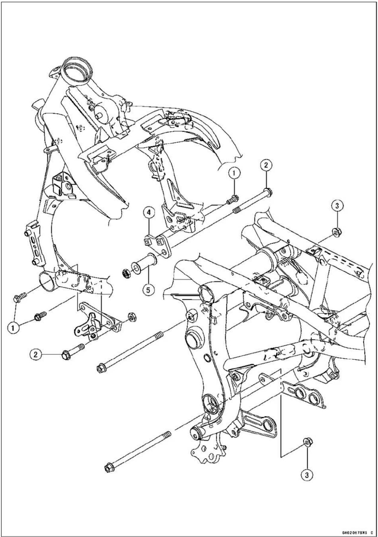
ExplodedView
| No.Fastener | Torque | Remarks | |||
| N·mkgf | mft·lb | ||||
| 1EngineMountingBracketBolts252.518 | |||||
| 2FrontEngineMountingBolts444.532 | |||||
| 3RearEngineMountingNuts444.532 | |||||
- EngineMountingBrackets
5.Collar
8-4 ENGINEREMOVAL/INSTALLATION
EngineRemoval/Installation
EngineRemoval
- Supporttherearpartoftheswingarmwithastand.
- Squeezethebrakeleverslowlyandholditwithaband [A].
WARNING
Besuretoholdthefrontbrakewhenremovingthe engine,orthemotorcyclemayfallover.Itcould causeanaccidentandinjury.

natural_image
Close-up of a motorcycle's handle and lever assembly with labeled component A (no text or symbols beyond label)CAUTION
Besuretoholdthefrontbrakewhenremovingthe engine,orthemotorcyclemayfallover.Theengine orthemotorcyclecouldbedamaged.
- Drain:
EngineOil(seeEngineOilChangeinthePeriodicMaintenancechapter)
Coolant(seeCoolantChangeinthePeriodicMaintenancechapter) - Remove:
Seat(seeSeatRemovalintheFramechapter)
LowerFairingandCenterFairing(seeFairingsectionin theFramechapter)
SideCovers(seeSideCoverRemovalintheFrame chapter)
FrameCovers(seeFrameCoverRemovalintheFrame chapter)
RadiatorandHoses(seeRadiatorandRadiatorFanRemovalintheCoolingSystemchapter) - Unscrewthelowerfairingbracketbolts(bothsides)[A] andremovethebrackets(bothsides)[B].
- Disconnecttheoilpressureswitchterminal[A].


natural_image
Mechanical assembly diagram showing components with no visible text or symbolsEngineRemoval/Installation
- Disconnectthecrankshaftsensorleadconnector[A].
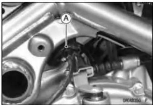
natural_image
Close-up mechanical assembly showing a valve labeled 'A' and a circular component (no readable text or symbols)- Remove:
ExhaustPipe(see Exhaust Pipe Removal in the Engine Top End chapter)
MufflerBody(see MufflerBody Removal in the Engine Top End chapter)
FuelTank(seeFuelTankRemovalintheFuelSystem (DFI)chapter)
AirSwitchingValveandHose(seeAirSwitchingValveRemovalintheEngineTopEndchapter)
AirCleanerHousing(seeAirCleanerHousingRemoval intheFuelSystem(DFI)chapter)
ThrottleBodyAssy(see ThrottleBodyRemovalinthe FuelSystem(DFI)chapter)
ClutchCable(seeClutchCableRemovalintheClutch chapter)
- Remove:
StickCoils[A]
BafflePlate[B]

- Removeordisconnect:
WaterTemperatureSensorLeadConnector[A] StarterMotorCable[B]
EngineGroundCableTerminalBolt[C]
AlternatorLeadConnector[D]
SidestandSwitchLeadConnector[E]
SpeedSensorLeadConnector[F]

8-6ENGINEREMOVAL/INSTALLATION
EngineRemoval/Installation
- Removetheenginesprocketcover(seeEngineSprocketRemovalintheFinalDrivechapter).
- RemovetheshiftpedalA.
- Disconnect: OxygenSensorLeadConnector[B] NeutralSwitchLeadTerminal[C]
- Removethebracket[D]andtheenginesprocketE.
- Remove: HornLeadsA HornBolt[B] Horn[C]
- Supporttheenginewithastandorjack[A].
○Putawoodenboard[B]onthesuitablestand.
- Removetheenginemountingbolts[C].
- Removetheenginemountingbracketbolts(bothsides) [D]andremovethebrackets[E].
- Removetheengine[F].
- Inserttherearenginemountingboltsfromtheleftsideof theengineandtightenthenuts.
- Installtheenginemountingbrackets[A]withthebolts[B].
- Insertthefrontenginemountingbolts[C]andtightenthe bolts.
○Positionthecollar[D]ontherightenginemounting bracket.
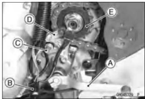

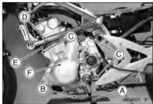

EngineRemoval/Installation
- Tighten:
Torque-RearEngineMountingNuts:44N·m(4.5kgf·m,32ft·lb)
FontEngineMountingBolts:44N·m(4.5kgf·m, 32ft·lb)
EngineMountingBracketbolts:25N·m(2.5kgf·m, 18ft·lb)
- Installtheenginesprocket(seeEngineSprocketInstallationintheFinalDrivechapter).
- Runtheleads, cables, and hosescorrectly (see Cable, Wire, and HoseRoutingsection in the Appendix chapter).
- Installtheremovedparts(seeappropriatechapters).
- Adjust:
ThrottleCables(see ThrottleControlSystemInspection inthePeriodicMaintenancechapter)
ClutchCable(seeClutchOperationInspectioninthePeriodicMaintenancechapter)
DriveChain(seeDriveChainSlackAdjustmentinthe PeriodicMaintenancechapter)
- Filltheenginewithengineoil(seeEngineOilChangein thePeriodicMaintenancechapter).
- Filltheenginewithcoolantandbleedtheairfromthecoolingsystem(seeCoolantChangeinthePeriodicMaintenancechapter).
- Adjusttheidling(seeIdleSpeedAdjustmentinthePeriodicMaintenancechapter).
Crankshaft/Transmission
TableofContents
ExplodedView....9-2
Specifications....9-6
SpecialToolsandSealant....9-9
CrankcaseSplitting....9-10
CrankcaseSplitting......9-10
CrankcaseAssembly....9-11
CrankshaftandConnectingRods.....9-17
CrankshaftRemoval....9-17
CrankshaftInstallation......9-17
ConnectingRodRemoval......9-17
ConnectingRodInstallation......9-18
Crankshaft/ConnectingRod Cleaning....9-21
ConnectingRodBend......9-21
ConnectingRodTwist......9-22
ConnectingRodBigEndSide Clearance....9-22
ConnectingRodBigEndBearing Insert/CrankpinWear....9-22
CrankshaftSideClearance......9-24
CrankshaftRunout......9-24
CrankshaftMainBearing Insert/JournalWear....9-24
Balancer....9-27
BalancerRemoval....9-27
BalancerInstallation....9-27
BalancerShaftBearing Insert/JournalClearance......9-27
Transmission.... 9-29
ShiftPedalRemoval....9-29
ShiftPedallInstallation....9-29
ExternalShiftMechanism Removal.... 9-29
ExternalShiftMechanism Installation.... 9-30
ExternalShiftMechanism Inspection.... 9-31
TransmissionAssyRemoval...... 9-32
TransmissionAssyDisassembly. 9-33
TransmissionAssyAssembly.....9-33
TransmissionAssyInstallation..... 9-34
TransmissionShaftRemoval..... 9-35
TransmissionShaftInstallation.... 9-35
TransmissionShaftDisassembly.9-36
TransmissionShaftAssembly.....9-36
ShiftDrumandForkRemoval.....9-39
ShiftDrumandForkInstallation...9-39
ShiftDrumDisassembly......9-39
ShiftDrumAssembly....9-39
ShiftForkBending....9-39
ShiftFork/GearGrooveWear.....9-39
ShiftFork GuidePin/Drum GrooveWear....9-40
GearDogandGearDogHole Damage.... 9-40
BallBearing,NeedleBearing,andOil
Seal.... 9-41
Ball and NeedleBearing Replacement.... 9-41
BallandNeedleBearingWear.....9-41
OilSealInspection....9-41
ExplodedView

ExplodedView
| No.Fastener | Torque | Remarks | |||
| N·mkgf·mft·lb | |||||
| 1 | ConnectingRodBigEndNuts | seeText← | ← ← | ||
| 2TimingRotorBolt404.130 | |||||
| 3 | Oil Plate Bolts | 9.8 | 1.0 | 87 in·lb | L |
| 4 | Breather Plate Bolts | 9.8 | 1.0 | 87 in·lb | L |
| 5 | Shift Shaft Return Spring Pin | 29 | 2.9 | 22 | L |
| 6 | Oil Pipe Bolts | 9.8 | 1.0 | 87 in·lb | L |
| 7 | CrankcaseBolts(M9, L =113mm) | 444.532 | MO,S | ||
| 8 | Crankcase Bolts (M9, L = 83 mm) | 44 | 4.5 | 32 | MO, S |
| 9 | Crankcase Bolts (M8, L = 73 mm) | 35 | 3.6 | 26 | MO, S |
| 10 | Crankcase Bolts (M8, L = 60 mm) | 35 | 3.6 | 26 | MO, S |
| 11 | Crankcase Bolts (M8, L = 110 mm) | 27.5 | 2.8 | 20 | S |
| 12 | Crankcase Bolts (M8, L = 50 mm) | 27.5 | 2.8 | 20 | S |
| 13 | CrankcaseBolts(M6) | 19.6 | 2.015 | S | |
| 14 | Upper Crankcase Bolts | 27.5 | 2.8 | 20 | S |
- Donotapplyanygreaseoroil.
G: Applygrease.
L: Applyanon-permanentlockingagent.
LG: Apply liquid gasket (Kawasaki Bond: 92104-1064).
M: Applymolybdenumdisulfidegrease.
MO: Applymolybdenumdisulfideoilsolution.
(mixture of the engine oil and molybdenum disulfide grease in a weight ratio 10:1)
R: ReplacementParts
S: Followthespecifictighteningsequence.
SS: Applysiliconesealant(ThreeBond1207B).
ExplodedView

ExplodedView
| No.Fastener | Torque | Remarks | |||
| N·mkgf·mft·lb | |||||
| 1 | GearPositioningLeverBolt | 121.2106in·lbL | |||
| 2TransmissionCaseBolts202.015 | |||||
| 3 | Shift Drum Cam Bolt | 12 | 1.2 | 106 in·lb | L |
| 4 | Shift Drum Bearing Holder Screw | 4.9 | 0.50 | 43 in·lb | L |
| 5 | Shift Rod Plate Bolt | 9.8 | 1.0 | 87 in·lb | |
| 6 | Neutral Switch Holder Screw | 4.9 | 0.50 | 43 in·lb | L |
| 7 | NeutralSwitch | 151.511 | |||
| 8 | Shift Shaft Cover Bolts | 9.8 | 1.0 | 87 in·lb | (L) |
| 9 | Shift Shaft Cover Screw | 4.9 | 0.50 | 43 in·lb | L |
EO:Applyengineoil.
G:Applygrease.
L: Applyanon-permanentlockingagent.
MO:Applymolybdenumdisulfideoilsolution.
(mixtureoftheengineoilandmolybdenumdisulfidegreaseinaweightratio10:1)
R:ReplacementParts
Specifications
| ItemStandardServiceLimit | ||||
| Crankshaft,ConnectingRodsConnectingRodBend-- TIR0.2/100mmConnectingRodTwistConnectingRodBigEndSideClearanceConnectingRodBigEndBearingInsert/Crankpin ClearanceCrankpinDiameter:Marking:None37.984~ 37.992mm○ConnectingRodBigEndInsideDiameter:Marking:None41.000~ 41.008mm○ConnectingRodBigEndBearingInsert Thickness:Brown1.475~ 1.480mmBlack1.480~ 1.485mmBlue1.485~ 1.490mm | 0.13~ 0.38mm(0.0051~ 0.0150in.)0.017~ 0.041mm(0.0007~ 0.0016in.)37.984~ 38.000mm(1.4954~ 1.4961in.) | (0.008/3.94in.)TIR0.2/100mm(0.008/3.94in.)0.58mm(0.023in.)0.08mm(0.0031in.)37.97mm(1.4949in.)---- | ||
| (1.4954~ 1.4957in.)37.993~ 38.000mm(1.4958~ 1.4961in.)41.000~ 41.016mm(1.6142~ 1.6148in.) | ---- | |||
| (1.6142~ 1.6145in.)41.009~ 41.016mm(1.6145~ 1.6148in.) | ---- | |||
| (0.05807~ 0.05827in.) | ---- | |||
| (0.05827~ 0.05846in.) | ---- | |||
| (0.05846~ 0.05866in.) | ---- | |||
| ConnectingRodBigEndBearingInsertSelection: | ||||
| Con-rodBigEnd BoreDiameter Marking | CrankpinDiameter Marking | BearingInsert | ||
| SizeColorPartNumber | ||||
| None | ○ | Brown92139-0116 | ||
| None | None | Black | 92139-0115 | |
| ○ | ○ | |||
| ○ | None | Blue | 92139-0114 | |
| ConnectingRodBoltStretch:(UsableRange)NewConnectingRodUsed Connecting RodCrankshaftSideClearance | 0.24~ 0.36mm(0.0094~ 0.0142in.)0.20~ 0.32 mm(0.0079~ 0.0126in.)0.05~ 0.20mm(0.0020~ 0.0079in.) | |||
Specifications
| ItemStandardServiceLimit | ||
| CrankshaftRunoutTIR0.02mm(0.0008in.) | orless | TIR0.05mm(0.0020in.) |
| CrankshaftMainBearingInsert/JournalClearance0.012~ 0.036mm(0.0005~ 0.0014in.) | 0.07mm(0.0028in.) | |
| CrankshaftMainJournalDiameter: | 37.984~ 38.000mm(1.4954~ 1.4961in.) | 37.96mm(1.4945in.) |
| Marking: | ||
| None37.984~ 37.992mm | (1.4954~ 1.4957in.) | -- -- |
| 137.993~ 38.000mm | (1.4958~ 1.4961in.) | -- -- |
| CrankcaseMainBearingInsideDiameter: | 41.000~ 41.016mm(1.6142~ 1.6148in.) | -- -- |
| Marking: | ||
| ○ | 41.000~ 41.008mm(1.6142~ 1.6145in.) | -- -- |
| None41.009~ 41.016mm | (1.6145~ 1.6148in.) | -- -- |
| CrankshaftMainBearingInsertThickness: | ||
| Brown1.490~ 1.494mm | (0.0587~ 0.0588in.) | -- -- |
| Black1.494~ 1.498mm | (0.0588~ 0.0590in.) | -- -- |
| Blue1.498~ 1.502mm | (0.0590~ 0.0591in.) | -- -- |
CrankshaftMainBearingInsertSelection:
| CrankcaseMain BearingInside DiameterMarking | CrankshaftMain JournalDiameter Marking | BearingInsert* | |
| SizeColor | PartNumber | ||
| ○ | 1 | Brown | 92028-1905 |
| None | 1 | Black | 92028-1904 |
| ○ | None | ||
| None | None | Blue | 92028-1903 |
*ThebearinginsertsforNos.1,2and3journalshaveoilgrooves.
| BalancerShaft | ||
| Balancer Shaft Bearing Insert/Journal Clearance | 0.011 ~ 0.033 mm(0.0004~ 0.0013in.) | 0.08mm(0.0031in.) |
| BalancerShaftJournalDiameter: | 27.987~ 28.000mm(1.1019~ 1.1024in.) | 27.96mm(1.1108in.) |
| Marking: | ||
| None | 27.987 ~ 27.993 mm(1.1019~ 1.1021in.) | -- -- |
| ○ | 27.994~ 28.000mm(1.1021~ 1.1024in.) | -- -- |
Specifications
| ItemStandardServiceLimit | ||||
| CrankcaseBearingBoreDiameter: | 31.000~31.016mm(1.2205~1.2228in.) | --- | ||
| Marking: | ||||
| ○ | 31.000~31.008mm(1.2205~1.2208in.) | --- | ||
| None31.009~31.016mm | (1.2208~1.2211in.) | --- | ||
| BalancerShaftBearingInsertThickness: | ||||
| Brown1.490~1.494mm | (0.0587~0.0588in.) | --- | ||
| Black1.494~1.498mm | (0.0588~0.0590in.) | --- | ||
| Blue1.498~1.502mm | (0.0590~0.0591in.) | --- | ||
| BalancerShaftBearingInsertSelection: | ||||
| BalancerShaftJournalDiameterMarking | BearingInsert*CrankcaseBearing | |||
| SizeColorPartNumber | ||||
| ○ | ○ | Brown92139-0119 | ||
| ○ | None | Black | 92139-0118 | |
| None | ○ | |||
| None | None | Blue | 92139-0117 | |
| *ThebearinginsertsforNos. 1,2journalshaveoilgrooves. | ||||
| TransmissionShiftForkEarThickness | 5.9~6.0mm(0.232~0.236in.) | 5.8mm(0.228 in.) | ||
| Gear Groove Width | 6.05~6.15 mm(0.238~0.242in.) | 6.25 mm(0.246 in.) | ||
| ShiftForkGuidePinDiameter | 6.9~7.0mm(0.272~0.276in.) | 6.8mm(0.268 in.) | ||
| ShiftDrumGrooveWidth | 7.05~7.20mm(0.278~0.283in.) | 7.3mm(0.287 in.) | ||
SpecialToolsandSealant
OutsideCirclipPliers: 57001-144

natural_image
Line drawing of a pair of pliers (no text or symbols on the tool itself)KawasakiBond: 92104-1064

BearingDriverSet: 57001-1129
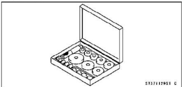
natural_image
Isometric line drawing of a box containing multiple circular components, no text or symbols presentCrankcaseSplitting
CrankcaseSplitting
- Remove:
Engine(seeEngineRemovalintheEngineRemoval/Installationchapter)
Cylinder(see CylinderRemovalintheEngineTopEnd chapter)
Pistons(seePistonRemovalintheEngineTopEnd chapter)
StaterMotor(seeStarterMotorRemovalintheElectrical Systemchapter)
Clutch(seeClutchRemovalintheClutchchapter)
TransmissionAssy(see TransmissionAssyRemoval)
AlternatorRotor(seeAlternatorRotorRemovalinthe ElectricalSystemchapter)
- Removetheuppercrankcasebolts(M8)[A]andthewashers.
- Removetheoilpan,reliefvalve,oilscreenandoilpipes (seeOilPanRemovalintheEngineLubricationSystem chapter).
- Removethelowercrankcasebolts.
○FirstlyloosentheM6bolts,secondlytheM8boltsand lastlytheM9bolts.
M6Bolts[A]
M8Bolts[B]
M9Bolts[C]andWashers
- Taplightlyaroundthecrankcasematingsurfacewitha plasticmallet,andsplitthecrankcase.Takecarenotto damagethecrankcase.

natural_image
Technical line drawing of a mechanical assembly (no text or symbols visible)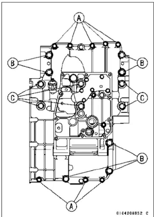
CrankcaseSplitting
★Iftheoilpieistoberemoved,followthenextprocedure. ○Unscrewthebolts[A]andremovetheoilpipe[B].

- Preparea5mmrod[B], and insertittotheholeofthe uppercrankcasehalf. - Removetheoilpipe[A], tapping[C]therodasshown.

★Ifthebreatherplate[A]istoberemoved,followthenext procedure. ○Removetheoilpipe(seeabove). ○Cutthegasketaroundtheplate[B]. ○Remove: BreatherPlateBolts[C] BreatherPlatewithPipe

CrankcaseAssembly
CAUTION
Theupperandlowercrankcasehalvesaremachinedatthefactoryintheassembledstate,sothe crankcasehalvesmustbereplacedasaset.
- Withahigh-flashpointsolvent,cleanoffthematingsurfacesofthecrankcaseshalvesandwipedry.
- Usingcompressedair, blowout the oil passages in the crankcase halves.
- If the oil plate [A] on the upper crank case half was removed, install it as shown.
- Applyanon-permanentlockingagenttotheoilplatebolts andtorquethem.
Torque-OilPlateBolts[B]:9.8N·m(1.0N·m,87in·lb)

CrankcaseSplitting
- Pressandinsert[A]thenewneedlebearing[B]forthe shiftdrumuntilitisbottomed.
SpecialTool-BearingDriverSet:57001-1129
- Pressandinsert[C]thenewneedlebearing[D]forthe shiftshaftsothatthebearingsurfaceisflushwiththeend ofthehole.
SpecialTool-BearingDriverSet:57001-1129
LowerCrankcaseHalf[E]
- Applysilicones equalant to the breather platematings surface [A] 1 mm (0.04 in.) or more thick, and then install the breather plate.
Sealant-ThreeBond1207B
NOTE
○ Maketheapplicationfinishwithin7minuteswhenthe liquidgaskettothematingsurfaceofthebreatherplate isapplied.
○ Moreoverfittheplateandtightentheboltsjustafter applicationoftheliquidgasket.
- Applyanon-permanentlockingagenttothethreadsandtightenthebolts[A].
Torque-BreatherPlateBolts:9.8N·m(1.0kgf·m,87in·lb)
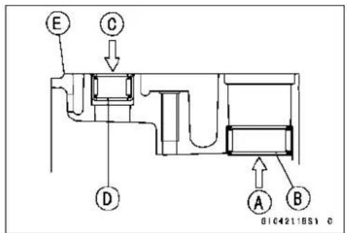


natural_image
Mechanical assembly with labeled components A, showing internal components and mounting holes (no readable text or symbols)• Installthebreatherpipe[A].
○Align thewhitemark [B] on the pipewith [C] on the breatherfittling.
○Installtheclamp[D]sothatthepinchportions[E]facethe whitemarks.

- Installtheoilpipe[A]sothatitsflange[B]touchesto the surface [C] of the upper crankcase half.
- Apply grease to the O-ring [D] on the oil pipe.

CrankcaseSplitting
-
Installthecrankshaftassemblyandthebalancershaftassemblyontheuppercrankcasehalf.
○Align[A]thetimingmarkonthebalancergear[B]withthe timingmarkonthebalancerdrivegear[C]ofthecrank-shaft. -
Besuretohangthecamshaftchain[A]onthecrankshaft.
- Besurethatthedowelpins[A]areinposition.
- Setthebearinggroove[A]onthepositioningring[B]as shown.
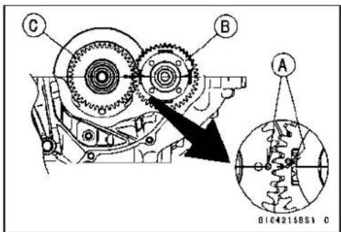

natural_image
Close-up of a mechanical engine component with gears and shafts (no visible text or symbols)

CrankcaseSplitting
- Applyliquidgasket[A]tothematingsurfaceofthelower crankcasehalf.
Sealant-KawasakiBond:92104-1064
NOTE
○ Especially, applyaliquidgasketcarefullysothatitshall befilleduponthegrooves.
CAUTION
Donotapplyliquidgasketaroundthecrankshaft mainbearinginserts, andoilpassageholes.
○Donotapplyliquidgaskettotheoilpassage[B].

G104217BH2 C
CrankcaseSplitting
- Fitthelowercrankcasehalftotheuppercrankcasehalf.
OInser[A]thebreatherpipe[B]ontheuppercrankcase halfthroughthehole[C]onthelowercrankcasehalf.
NOTE
○ Maketheapplicationfinishwithin20minuteswhen theliquidgaskettothematingsurfaceofthelower crankcasehalfisapplied.
○Moreoverfitthecaseandtightenthecaseboltsjust afterfinishingtheapplicationoftheliquidgasket.
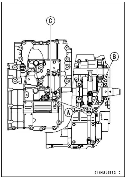
○The M9 bolts [1 \~ 6] (see the next figure) have copper platedwashers. Replacethemwithnewones.
- Applymolybdenumdisulfideoilsolutiontobothsides[A] oftheM9boltswashersandthethreads[B]oftheM9 bolts.
- Applymolybdenumdisulfideoilsolutiontoflange[A]and thethreads[B]oftheM8boltswhichistighteningorderis [7\~10]only(seethenextfigure).
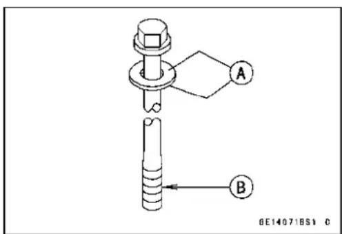

CrankcaseSplitting
- Tightenthelowercrankcaseboltsusingthefollowing steps.
○Followingthesequencenumbersonthelowercrankcase half,tightentheM9bolts[1,2]L=113mm(4.45in.)with washers.
Torque-CrankcaseBolts(M9):44N·m(4.5kgf·m,32ft·lb)
○TightentheM9bolts[3,4]L=83mm(3.27in.)withwashers.
Torque-CrankcaseBolts(M9):44N·m(4.5kgf·m,32ft·lb)
○TightentheM9bolts[5,6]L=113mm(4.45in.)with washers.
Torque-CrankcaseBolts(M9):44N·m(4.5kgf·m,32ft·lb)
○TightentheM8bolts[7\~10].
Torque-CrankcaseBolts(M8):35N·m(3.6kgf·m,26ft·lb)
○TightentheM8boltsA.
Torque-CrankcaseBolts(M8):27.5N·m(2.8kgf·m,20ft·lb)
○TightentheM6bolts[B].
Torque-CrankcaseBolts(M6):19.6N·m(2.0kgf·m,15ft·lb)
- Tightentheuppercrankcasebolts.
- Theuppercrankcaseboltshavecopperplatedwashers.
-Replacethemwithnewones.
Torque-UpperCrankcaseBolts(M8)[A]:27.5N·m(2.8 kgf·m,20ft·lb)
- Aftertighteningallcrankcasebolts, check the following items.
○Crankshaftandbalancershaftsturnfreely.
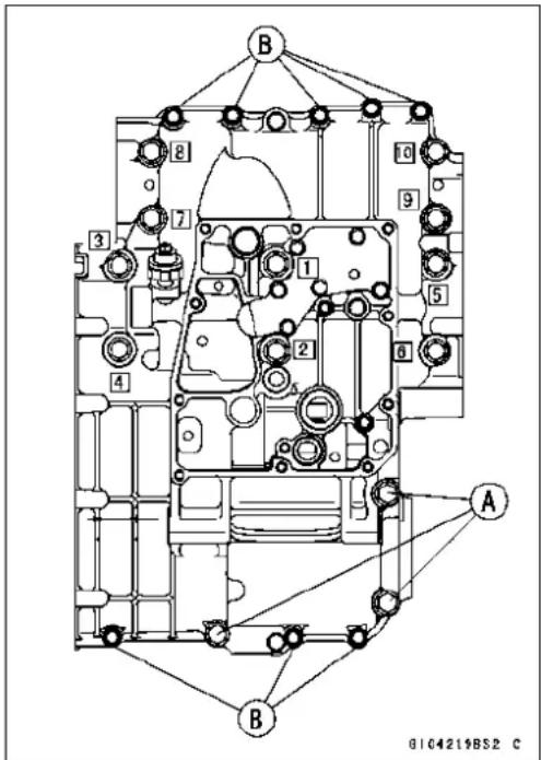
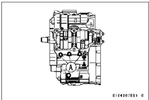
natural_image
Technical line drawing of a mechanical assembly with no visible text or symbolsCrankshaftandConnectingRods
CrankshaftRemoval
- Splitthecrankcase(seeCrankcaseSplitting).
- Removethecrankshaft[A].
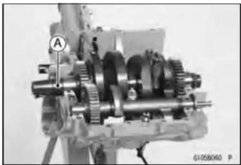
natural_image
Mechanical gear assembly with labeled component A (no readable text or symbols)CrankshaftInstallation
CAUTION
Ifthecrankshaft,bearinginserts,orcrankcase halvesarereplacedwithnewones,selectthebearinginsertsandcheckclearancewithaplastigage (pressgauge)beforeassemblingenginetobesure thecorrectbearinginsertsareinstalled.
- Applymolybdenumdisulfideoilsolutiontothecrankshaft mainbearinginserts.
○Align[A]thetimingmarkonthebalancergear[B]withthe timingmarkonthebalancerdrivegear[C]ofthecrankshaft. - Installthecrankshaftwiththecamshaftchain[A]hanging onit.


natural_image
Close-up of a mechanical engine component with gears and shafts, no visible text or symbolsConnectingRodRemoval
- Splitthecrankcase(seeCrankcaseSplitting).
- Removetheconnectingrodnuts[A].
- Removethecrankshaft.
NOTE
○Markandrecordthelocationsoftheconnectingrods andtheirbigendcapssothattheycanbereassembled intheiroriginalpositions.
- Removetheconnectingrodsfromthecrankshaft.

CAUTION
Discardtheconnectingrodbolts. Topreventdamagetothecrankpinsurfaces, donotallowtheconnectingrodboltstobumpagainstthecrankpins.
9-18CRANKSHAFT/TRANSMISSION
CrankshaftandConnectingRods
ConnectingRodInstallation
CAUTION
Tominimize vibration, the connecting rod should havethesameweightmark.
BigEndCap[A]
ConnectingRod[B]
WeightMark,Alphabet[C]
DiameterMark[D]:“ ○” or nomark
CAUTION
If the connecting rods, bigendbearing inserts, or crankshaft are replaced with new ones, select the bearing insert and check clearance with laplasti-gage (press gauge) before assembling engineetobe sure the correct bearing inserts are installed.
- Applymolybdenumdisulfidegrease[A]totheoutersurfaceoftheupperinsertandtheinnersurfaceoftheconnectingrodbigend.
- Applymolybdenumdisulfideoilsolution[B]totheinner surfacesofupperandlowerbearinginserts.
○Themolybdenumdisulfideoilsolutionisamixtureofengineoilandmolybdenumdisulfidegreasewithaweight ratio(10:1).
○Donotapplyanygreaseoroil[C]tothecapinsideand capinsertoutside.
○Installtheinsertssothattheirnails[D]areonthesame sideandfitthemintotherecessoftheconnectingrodand cap.
CAUTION
Wrongapplicationofoilandgreasecouldcause bearingdamage.
Wheninstallingtheinserts[A],becarefulnottodamage theinsertsurfacewiththeedgeoftheconnectingrod[B] orthecap[C].Onewaytoinstallinsertsisasfollows: Installation[D]toCap Installation[E]toConnectingRod Push[F] SpareDowelPin[G] ConnectingRodBolts[H]
- Installthecapontheconnectingrod, aligningtheweight anddiametermarks.
- Removedebrisandcleanthesurfaceofinserts.
- Applymolybdenumdisulfideoilsolution[MO]tothe threadsandseatingsurfacesofthebigendnutsand bolts.
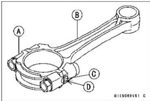
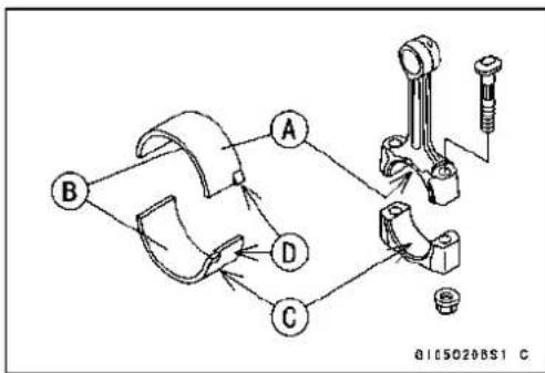

CrankshaftandConnectingRods
- Installthecrankshaft(seeCrankshaftInstallation).
- Installeachconnectingrodonitsoriginalcrankpin.
NOTE
○Installeachconnectingrodsothatitsoiljet[A]facesthe exhaustside(thefront[B])(seeEngineOilFlowChart intheEngineLubricationSystemchapter).

○Theconnectingrodbigendisboltedusingthe"plastic regionfasteningmethod".
- Thismethodpreciselyachievestheneededclamping forcewithoutexceedingitunnecessarily,allowingthe useofthinner,lighterboltsfurtherdecreasingconnectingrodweight.
- There are two types of the plastic region fastening. One is abolt length measurement method and other is a rotation angle method. Observe one of the following two, but the bolt length measurement method is preferable because this is more reliable way to light the big end nuts.
CAUTION
Theconnectingrodboltsaredesignedtostretch whentightened.Neverreusetheconnectingrod bolts.Seethetablebelowforcorrectboltandnut usage.
CAUTION
Becarefulnottovertightenthenuts. Theboltsmustbepositionedontheseatingsurface correctlytopreventtheboltheadsfromhittingthe crankcase.
(1) BoltLengthMeasurementMethod
- Besuretocleanthebolts, nuts, and connecting rods thoroughly with a high-flash points solvent, because the new connecting rods, bolts, and nuts are treated with an anti-rust solution.
WARNING
Cleanthebolts, nuts, and connectingrodsinawell-ventilated area, and take care that there is nospark or flame any where near the working area. This includes any appliance with a pilot light. Because of the danger of highly flammable liquids, donot use gasoline or low flash points solvent to clean them.
CAUTION
Immediately dry the bolts and nuts with compressed air after cleaning. Clean and dry the bolts and nuts completely.
CrankshaftandConnectingRods
• Installnewboltsinreusedconnectingrods.
- Dentbothboltheadandbolttipwithapunchasshown.
- Beforetightening, useapointmicrometer[A]tomeasure thelengthofnewconnectingrodboltsandrecordthevaluestofindtheboltstretch.
ConnectingRod[B]
Markherewithapunch[C].
Nuts[D]
Fitmicrometerpinsintopunchmarks[E].
- Applyasmallamountofmolybdenumdisulfideoilsolution tothefollowing:
ThreadsofNutsandBolts
SeatingSurfacesofNutsandCon-rods - Tightenthebigendnutsuntiltheboltelongationreaches thelengthspecifiedinthetable.
- Checkthelength[F]oftheconnectingrodbolts.
★Ifthestretchismorethantheusablerange,thebolthas stretchedtoomuch.Anoverelongatedboltmaybreakin use.
| BoltLengthaftertightening | - | BoltLengthbeforetightening | = | BoltStretch |
| ConnectingRod Assy | BoltNut | UsableRangeof ConnectingRod BoltStretch | |
| New | Usethebolts attachedto newcon-rod. | Attachedto newcon-rod | 0.24~0.36mm(0.0094~0.0142in.) |
| New | |||
| Used | Replacethe boltswithnew ones. | Used | 0.20~0.32mm(0.0079~0.0126in.) |
| New |
(2)RotationAngleMethod
★Ifyoudon'thaveapointmicrometer,youmaytightenthe nutsusingthe"RotationAngleMethod".
- Besuretocleantheboltsandnutsthoroughlywithahigh -flashpointsolvent,becausethenewboltsandnutsare treatedwithananti-rustsolution.
WARNING
Cleantheboltsandnutsinawell-ventilatedarea, andtakecarethatthereisnosparkorflameany-whereneartheworkingarea. Thisincludesanyappliancewithapilotlight.Becauseofthedanger orhighlyflammableliquids,donotusegasolineor low-flashpointsolventstocleanthem.
CAUTION
Immediately dry the bolts and nuts with compressed air after cleaning.
Cleananddrytheboltsandnutscompletely.

CrankshaftandConnectingRods
- Installnewboltsinreusedconnectingrods.
- Applyasmallamountofmolybdenumdisulfideoiltothe following:
Threads[A]ofNutsandBolts SeatingSurfaces[B]ofNutsandCon-rods

- First, tightenthenutstothespecifiedtorque. Seethe tablebelow.
- Next,tightenthenuts 120^±5^ .
OMark[A]theconnectingrodbigendcapsandnutssothat nutscanbeturned120°[B]properly.
| ConnectingRod Assy | BoltNut | Torque+AngleN·m(kgf·m,ft·lb) | |
| New | Usethebolts attachedto newcon-rod. | Attachedto newcon-rod | 18(1.8,13.0)+120° |
| New | 20(2.0,14.5)+120° | ||
| Used | Replacethe boltswith newones. | Used | 24(2.4,17.4)+120° |
| New | 25(2.6,18.8)+120° |

chemical
Chemical reaction diagram showing transformation of compound A to compound B with electron movement and structural changeCrankshaft/ConnectingRodCleaning
- Afterremovingtheconnectingrodsfromthecrankshaft, cleanthemwithahigh-flashpointsolvent.
- Blowthecrankshaftoilpassageswithcompressedairto removeanyforeignparticlesorresiduethatmayhave accumulatedinthepassages.
ConnectingRodBend
- Removetheconnectingrodbigendbearinginserts, and reinstalltheconnectingrodbigendcap.
- Selectanarbor[A]ofthesamediameterastheconnectingrodbigend, and insert the earborthrough the connectingrodbigend.
- Selectanarborofthesamediameterathestepistonpin andatleast100mm(3.94in.)long,andinsertthearbor [B]throughtheconnectingrodsmallend.
- Onasurfaceplate, setthebig-endarboronVblock[C].
- With the connecting rod held vertically, use a height gauge to measure the difference in the height of the arborabovethesurfaceplate over a 100 mm (3.94 in.) length to determine the amount of connecting rod bend.
★ Ifconnectingrodbendexceedstheservicelimit, theconnectingrodmustbereplaced.

ConnectingRodBend
Service Limit: TIR0.2/100mm(0.008/3.94in.)
CrankshaftandConnectingRods
ConnectingRodTwist
- Withthebig-endarbor[A]stillonVblock[C], hold the connectingrodhorizontally and measure the amount that the arbor[B] varies from being paralleled with the surface plateover a 100mm (3.94in.) length of the arbortode-terminethe amount of connecting rodtwist.
★Ifconnectingrodtwistexceedstheservicelimit,theconnectingrodmustbereplaced.
ConnectingRodTwist
ServiceLimit:TIR0.2/100mm(0.008/3.94in.)
ConnectingRodBigEndSideClearance
- Measureconnectingrodbigendsideclearance.
○Insertathicknessgauge[A]betweenthebigendandeithercrankwebtodetermineclearance.
ConnectingRodBigEndSideClearance
Standard: 0.13 \~ 0.38 mm (0.0051 \~ 0.0150 in.)
ServiceLimit:0.58mm(0.023in.)
★Iftheclearanceexceedstheservicelimit,replacetheconnectingrodwithnewoneandthencheckclearanceagain. Ifclearanceistoolargeafterconnectingrodreplacement, thecrankshaftalsomustbereplaced.
ConnectingRodBigEndBearingInsert/Crankpin Wear
- Measurethebearinginsert/crankpin[B]clearancewith plastigage[A].
- Tightenthebigendnutstothespecifiedtorque(seeConnectingRodInstallation).
NOTE
○ Donotmovetheconnectingrodandcrankshaftduring clearancemeasurement.
CAUTION
Aftermeasurement, replacetheconnectingrod bolts.
Connecting Rod Big End Bearing Insert/Crankpin Clearance
Standard: 0.017 \~ 0.041 mm (0.0001 \~ 0.0016 in.)
ServiceLimit: 0.08mm(0.0031in.)
★Iftheclearanceiswithinthestandard,nobearingreplacementisrequired.
★Iftheclearanceisbetween0.042mm(0.00165in.)and theservicelimit(0.08mm,0.0031in.),replacethebearing inserts [A] with inserts painted blue [B]. Check insert/crankpinclearancewiththeplastigage. Theclear-ancemayexceedthestandardslightly,butitmustnotbe lessthanthemminuminordertoavoidbearingseizure.
★ If the clearance exceed stheservicelimit, measure the diameter of the crankpins.
CrankpinDiameter
Standard: 37.984 \~ 38.000 mm (1.4954 \~ 1.4961 in.)
ServiceLimit:37.97mm(1.4949in.)


natural_image
Close-up of mechanical gears and shafts with a labeled section A, no readable text or symbols present.

CrankshaftandConnectingRods
★Ifanycrankpinhaswornpasttheservicelimit,replace the crankshaftwithanewone.
★ Ifthemeasuredcrankpindiametersarenotlessthanthe servicelimit, butdonotcoincidewiththeoriginaldiameter markingsonthecrankshaft, makenewmarksonit.
CrankpinDiameterMarks
None 37.984 \~ 37.992 mm (1.4954 \~ 1.4957 in.)
37.993 \~ 38.000 mm (1.4958 \~ 1.4961 in.)
Δ:CrankpinDiameterMarks," ○" or n o m a r k.
- Measure the connecting rodbigend insided diameter, and markeach connecting rodbigend in accordance with the insided diameter.
- Tightentheconnectingrodbigendnutstothespecified torque(seeConnectingRodInstallation).
NOTE
○ Themarkalreadyonthebigendshouldalmostcoincide withthemeasurement.

ConnectingRodBigEndInsideDiameterMarks
None 41.000 \~ 41.008 mm (1.6142 \~ 1.6145 in.)
☐ 41.009 \~ 41.016 mm (1.6145 \~ 1.6148 in.)
Big End Cap [A]
ConnectingRod[B]
WeightMark,Alphabet[C]
DiameterMark(AroundWeightMark)[D]:“ ○” or no mark

- Selecttheproperbearinginsert[A]inaccordancewiththe combinationoftheconnectingrodandcrankshaftcoding. SizeColor[B]
| Con-rodBigEndInsideDiameterMarking | CrankpinDiameterMarking | BearingInsert | |
| SizeColor | PartNumber | ||
| None | ○ | Brown921 | 39-0116 |
| None | None | Black | 92139-0115 |
| ○ | ○ | ||
| ○ | None | Blue | 92139-0114 |

- Installthenewinsertsintheconnectingrodandcheck insert/crankpinclearancewiththeplastigage.
CrankshaftandConnectingRods
CrankshaftSideClearance
- Insertathicknessgauge[A]betweenthecrankcasemain bearingandthecrankwebattheNo.2journal[B]to determineclearance.
★Iftheclearanceexceedstheservicelimit,replace the crankcasehalvesasaset.
NOTE
○ Theupperandlowercrankcasehalvesaremachined atthefactoryintheassembledstate,sothecrankcase halvesmustbereplacedasaset.
CrankshaftSideClearance
Standard: 0.05 \~ 0.20 mm (0.0020 \~ 0.0079 in.)
ServiceLimit:0.40mm(0.0157in.)
CrankshaftRunout
- Measurethecrankshaftrunout.
★Ifthemeasurementexceedstheservicelimit,replace the crankshaft.
CrankshaftRunout
Standard: TIR0.02mm(0.0008in.) or less
ServiceLimit:TIR0.05mm(0.0020in.)
CrankshaftMainBearingInsert/JournalWear
- Usingaplastigage(pressgauge)[A],measurethebearinginsert/journal[B]clearance.
NOTE
○ Tightenthecrankcaseboltstothespecifiedtorque(see CrankcaseAssembly).
○ Donotturnthecrankshaft during clearancemeasurement.
○ Journal clearance less than 0.025 mm (0.00098 in.) can not be measured by plastigage, however, using genuine partsmaintainstheminimumstandardclearance.
CrankshaftMainBearingInsert/JournalClearance
Standard: 0.012 \~ 0.036 mm (0.0005 \~ 0.0014 in.)
ServiceLimit: 0.07mm(0.0028in.)
★If the clearance is within the standard, nobearing replacement is required.
★Iftheclearanceis between0.037mm(0.0015in.)andthe servicelimit(0.07mm,0.0028in.),replacethebearinginserts[A]withinsertspainted blue[B].Checkinsert/journal clearance withtheplastigage.Theclearance mayexceed thestandardslightly,butitmustnotbelessthanthemiminuminordertoavoidbearingseizure.
★Iftheclearanceexceedstheservicelimit,measurethe diameterofthecrankshaftmainjournal.
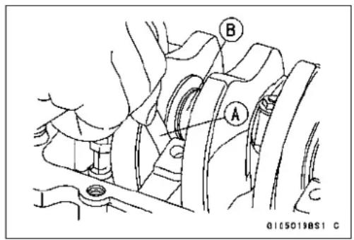
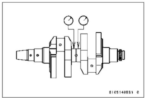
natural_image
Technical line drawing of a mechanical assembly with no visible text or symbols
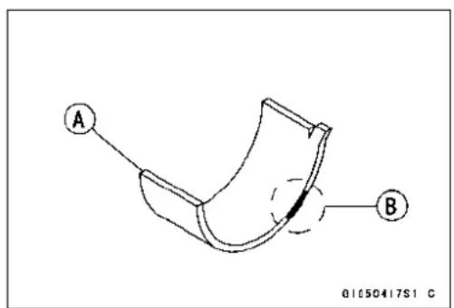
CrankshaftandConnectingRods
CrankshaftMainJournalDiameter
Standard: 37.984 \~ 38.000 mm (1.4954 \~ 1.4961 in.)
ServiceLimit:37.96mm(1.4945in.)
★Ifanyjournalhaswornpasttheservicelimit,replace the crankshaftwithanewone.
★ Ifthemeasuredjournaldiametersarenotlessthanthe servicelimit, butdonotcoincidewiththeoriginaldiameter markingsonthecrankshaft, makenewmarksonit.
CrankshaftMainJournalDiameterMarks
None 37.984 \~ 37.992 mm (1.4954 \~ 1.4957 in.)
1 37.993 \~ 38.000 mm (1.4958 \~ 1.4961 in.)
☐:CrankshaftMainJournalDiameterMarks,"1"orno mark.
- Measurethemainbearinginsidediameter, and mark the uppercrankcasehalfinaccordance with the insidediameter.
CrankcaseMainBearingInsideDiameterMarks: "O" or nomark.
- Tightenthecrankcaseboltstothespecifiedtorque(see CrankcaseAssembly).
NOTE
○ Themarkalreadyontheuppercrankcasehalfshould almostcoincidewiththemeasurement.
CrankcaseMainBearingInsideDiameterMarks
○ 41.000 \~ 41.008 mm (1.6142 \~ 1.6145 in.)
None 41.009 \~ 41.016 mm (1.6145 \~ 1.6148 in.)
□□□:CrankcaseMainBearingInsideDiameterMarks," ○" markornomark
[A]No.1Journal
[B]No.2Journal
[C]No.3Journal
- Selecttheproperbearinginsert[A]inaccordancewiththe combinationofthecrankcaseandcrankshaftcoding. SizeColor[B]


| CrankcaseMainBearingInsideDiameterMarking | CrankshaftMainJournalDiameterMarking | BearingInsert* | |
| SizeColorPartNumber | |||
| ○ | 1 | Brown | 92028-1905 |
| None | 1 | Black | 92028-1904 |
| ○ | None | ||
| None | None | Blue | 92028-1903 |
*ThebearinginsertsforNos.1,2and3journalshaveoilgroove.
9-26CRANKSHAFT/TRANSMISSION
CrankshaftandConnectingRods
- Installthenewinsertsinthecrankcasehalvesandcheck insert/journalclearancewiththeplastigage.
Balancer
BalancerRemoval
- Splitthecrankcase(seeCrankcaseSplitting).
- Pullthebalancershaftwiththebalancergearoutofthe crankcase.
BalancerInstallation
- Applymolybdenumdisulfideoilsolutiontotheinsideof thebalancershaftbearinginsert.
- Align[A]thetimingmarkonthebalancergear[B]withthe timingmarkonthebalancerdrivegear[C]ofthecrankshaft.
- Assemblethecrankcase(seeCrankcaseAssembly).
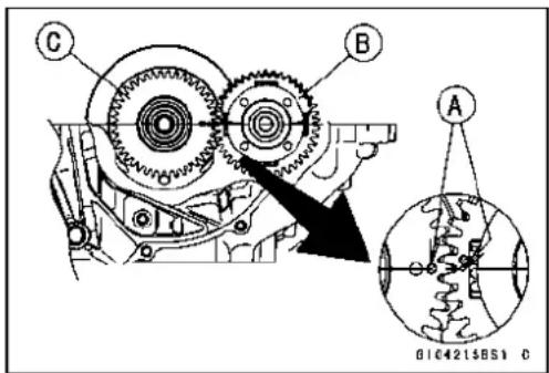
BalancerShaftBearingInsert/JournalClearance
- Measurethebearinginsert/journalclearanceusinga plastigage.
○Splitthecrankcaseandwipeeachbearinginsertandjournalsurfacecleanofoil.
○Cutstripsofplastigagetobearinginsertwidth, and place astriponeachjournalparalleltothebalancershaftsothat theplastigagewillbecompressedbetweenthejournal andthebearinginsert.
○Installthelowercrankcasehalf, andtightenthecasebolts tothespecifiedtorque(seeCrankcaseAssembly).
NOTE
○Donotturnthebalancershaftduringclearancemeasurement.
- Removethelowercrankcasehalfandmeasuretheplastigagewidth[A]todeterminethebearinginsert/journal[B] clearance.
BalancerShaftBearingInsert/JournalClearance
Standard: 0.011 \~ 0.033 mm (0.0004 \~ 0.0013 in.) ServiceLimit:0.08mm(0.0031in.)
★ If the clearance is within the standard, nobearing insert replacement is required.
★ If the clearance is between 0.050 mmand the service limit (0.09 mm), replace the bearing inserts [A] within- sertspainted blue [B] Check insert/journal clearance with aplastigage. The clearancemay exceed the standard slightly, but it must not be less than the minimum in order to avoid bearing seizure.
★ If the clearance exceed stheservicelimit, measure the diameter of the balancershaft journal.
BalancerShaftJournalDiameter
Standard: 27.987 \~ 28.000 mm (1.1019 \~ 1.1024 in.)
ServiceLimit: 27.96mm(1.1008in.)


Balancer
★lfeitherjournalhaswornpasttheservicelimit,replace thebalancershaftwithanewone.
★Ifthemeasuredjournaldiametersarenotlessthanthe servicelimit,butdonotcoincidewiththeoriginaldiameter markingsonthebalancershaft,writenewmarksonit.
BalancerShaftDiameterMarks
None 27.987 \~ 27.993 mm (1.1019 \~ 1.1021 in.)
27.994 \~ 28.000 mm (1.1021 \~ 1.1024 in.)
Δ:BalancerShaftJournalDiameterMarks," "m a r k o r nomark.

- Putthelowercrankcasehalfontheuppercrankcasehalf withoutbearinginserts, andtightenthecaseboltstothe specified torque and sequence (seeCrankcaseAssembly).
- Measurethecrankcasebearingborediameterforthebalancershaft,andmarktheuppercrankcasehalfinaccordancewiththeborediameter.
NOTE
○ Themarkalreadyontheuppercrankcasehalfshould almostcoincidewiththemeasurement.
CrankcaseBearingBoreDiameterMarks
31.000 \~ 31.008 mm (1.2205 \~ 1.2208 in.)
None 31.009 \~ 31.016 mm (1.2208 \~ 1.2211 in.)
□□:CrankcaseBearingBoreDiameterMarks," ○" m a r k ornomark.
[A]No.1Journal
[B]No.2Journal

- Selecttheproperbearinginsertinaccordancewiththe combinationofthecrankcaseandthebalancershaftcoding.
- Installthenewinsertsinthecrankcaseandcheckinsert/journalclearancewithaplastigage.
BalancerShaftBearingInsertSelection
| BearingBoreDiameter Mark | CrankshaftMain JournalDiameterMark | BearingInsert*CrankcaseMain | |
| SizeColor | PartNumber | ||
| ○ | ○ | Brown | 92139-0119 |
| ○ | None | Black | 92139-0118 |
| None | ○ | ||
| None | None | Blue | 92139-0117 |
Transmission
ShiftPedalRemoval
- Remove: ShiftLeverBolt[A] ShiftLever[B]

ShiftPedalInstallation
- Alignthemark[A]ontheshiftshaftwiththeslit[B]onthe shiftlever.
- Tightentheshiftleverboltsecurely.

- Besuretheshiftpedalpositionisasshown. ShiftPedalDamper[A] Bottom[B]ofLeftFootpegStay ShiftLever[C] Bolt[D]ofLeftFootpegStay
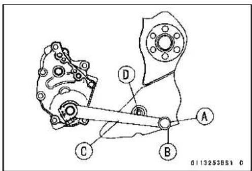
ExternalShiftMechanismRemoval
- Remove:
EngineOil(drain,seeEngineOilChangeinthePeriodic Maintenancechapter)
ShiftPedal(seeShiftPedalRemoval)
EngineSprocket(seeEngineSprocketRemovalinthe
FinalDrive)
NeutralSwitchLeadConnector(Disconnect)
ShiftShaftCoverBolts[A]
ShiftShaftCoverScrew[B]
ShiftShaftCover[C]

- Removetheshiftshaftassembly[A].

9-30CRANKSHAFT/TRANSMISSION
Transmission
- Remove:
Clutch(seeClutchRemovalintheClutchchapter)
GearPositioningLeverBolt[A]
GearPositioningLever[B], Spacer, WasherandSpring
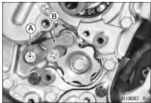
ExternalShiftMechanismInstallation
• Installthegearpositioninglever[A]asshown.
Spring[B]
Washer[C]
Spacer[D]
Bolt[E]
○Fookthespringatgearpositioninglever,pushingup[F] thefookportion,asshown.
- Applyanon-permanentlockingagenttothegearpositioningleverboltandtorqueit.
Torque-GearPositioningLeverBolt:12N·m(1.2kgf·m, 106in·lb)
• Installtheshiftshaftassembly.
○Apply[A]molybdenumdisulfideoilsolutionotherubbingsurfacebetweenthelever[B]andpawl[C]andmove themtwoorthreetimesupanddowntolubricatethem.

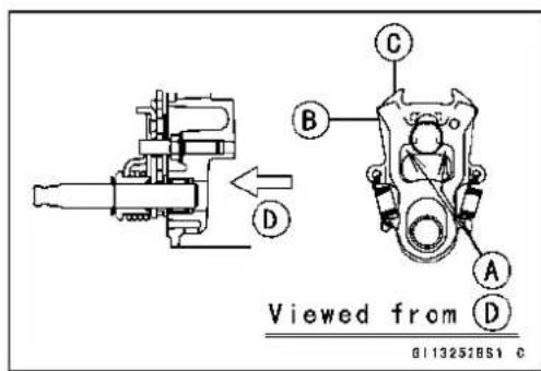
○Besurethatthewasher[A]isontheshaft.
○Besurethatthespringhookportions[B]areasshown.

ShiftShaftCoverScrew:4.9N·m(0.50kgf·m,43in·lb)
ExternalShiftMechanismInspection
- Examinetheshiftshaft[A]foranydamage.
★ Iftheshaftisbent, straightenorreplaceit.
★Iftheserration[B]aredamaged,replacetheshaft.
★ Ifthesprings[C]aredamagedinanyway, replacethem.
★ Iftheshiftmechanismarm[D]isdamagedinanyway, replacethearm.
- Checkthereturnspringpin[A]isnotloose.
★ Ifitisloose, unscrewit, applyanon-permanentlocking agenttothethreads, and tightenit.
Torque-ShiftShaftReturnSpringPin:29N·m(2.9kgf·m, 21ft·lb)


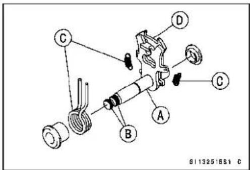

natural_image
Close-up mechanical assembly with labeled component A (no readable text or symbols)Transmission
- Check the gear positioninglever[A] and it spring for breaksordistortion.
★Iftheleverorspringaredamagedinanyway,replace them. - Visuallyinspecttheshiftdrumcam[B].
★Iftheyarebadlywornoriftheyshowanydamage,replace it.

TransmissionAssyRemoval
- Remove:
ShiftShaftAssembly(seeExternalShiftMechanismRemoval)
NeutralSwitchHolderBolt[A]
NeutralSwitchHolder[B]andPin
ShiftDrumHolder[C]andPin
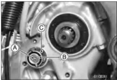
- Remove:
Collar[A]
O-ring[B]
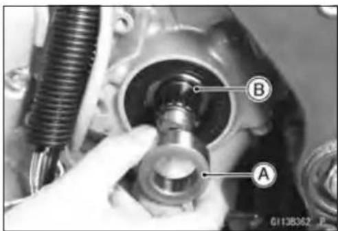
- Remove:
Clutch(seeClutchRemovalintheClutchchapter)
TransmissionCaseBolts[A]
★Ifthetransmissionassyistobedisassembled, following.
ShiftRodPlateBolt[B]
ShiftRodPlate[C]
GearPositioningLeverBolt[D]
GearPositioningLever[E]withSpring,Washerand
Spacer

- Pullthetransmissionassy[A]outofthecrankcase.
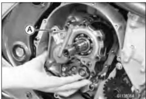
natural_image
Close-up of a mechanical assembly with gears and a hand holding a component (no visible text or symbols)Transmission
TransmissionAssyDisassembly
- Removethetransmissionassy(seeTransmissionAssy Removal)
- Removethefollowingfromthetransmissioncase[A]. ShiftRods[B] ShiftForks[C] DriveShaft[D] OutputShaft[E]
- Remove: ShiftDrumCamBolt[A] ShiftDrum[B]andPin ShiftDrum[C]
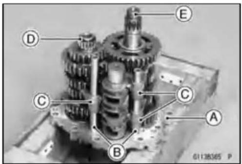

TransmissionAssyAssembly
- Whenthenewallbearings[A]areinstalledinthetransmissioncase[B],pressandinsertthemuntiltheyarebotomed.
SpecialTool-BearingDriverSet57001-1129

Transmission
- Installthefollowingonthetransmissioncase[A].
ShiftDrum[B]
Pin[C]
ShiftDrumCam[D]
○Alignthepinwiththeholeontheshiftdrumcam.
- Applyanon-permanentlockingagenttotheshiftdrum camboltandtorqueit.
Torque-ShiftDrumCamBolt:12N·m(1.2kgf·m,106in·lb)
• Installthefollowingasaset.
DriveShaft[F]
OutputShaft[G]
- Installtheforksasshown.
○Positiontheone[H]withshortestearsonthedriveshaft andplacethepininthecentergrooveintheshiftdrum.
○Thetwoforks[J]ontheoutputshaftareidentical.
- Installtheshiftrods,notingthegrooveposition.
○Therod[K]lengthoftheoutputshaftsideisshorterthan therod[L]lengthofthedriveshaftside.
- ApplymolybdenumdisulfideoilsolutiontothetransmissiongearsshownwithXmarks[M].
- Besurethatthespacer[P]isontheoutputshaft.

G113244BH2 C
TransmissionAssyInstallation
- Assemblethetransmissionassy(seeTransmissionAssy Assembly).
- Besurethatthedowelpins[A]areinposition.
- ApplygreasetotheO-ring[B]ontheoilpipe.
- Installthetransmissionassyonthecrankcase.
- Tightenthetransmissioncasebolts.
Torque-TransmissionCaseBolts:20N·m(2.0kgf·m,15ft·lb)
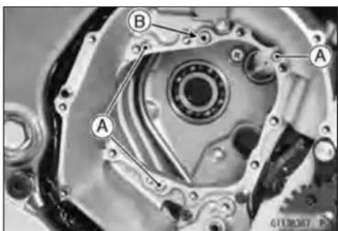
Transmission
- Install the gear positioninginglever (see External Shift Mechanism Installation).
• Installtheshiftrodplate.
Torque-ShiftRodPlateBolt:9.8N·m(1.0kgf·m,87in·lb) - Setthegearpositioninglevertotheneutralposition[A].
- Checkthatthedriveandoutputshaftturnfreely.
- Install: Pin[A] ShiftDrumHolder[B] Pin[C] NeutralSwitchHolder[D] NeutralSwitchHolderScrew[E]
○Applyanon-permanentlockingagenttotheneutralswitch holderscrewandtorqueit.
Torque-NeutralSwitchHolderScrew:4.9N·m(0.50kgf·m, 43in·lb)
- ApplygreasetotheO-ring[A]andinstallitsposition[B]ontheoutputshaft.
- Applygreasetothelipoftheoilseal[C].
- Installthecollar[D].

natural_image
Close-up of mechanical components with a highlighted circular area labeled 'A' (no readable text or symbols)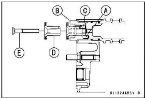

TransmissionShaftRemoval
- Removethetransmissionassy(seeTransmissionAssyRemoval).
- Remove: ShiftRods[A] ShiftForks[B] DriveShaft[C]andOutputShaft[D]

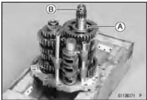
TransmissionShaftInstallation
- Besurethatthespacer[A]isontheoutputshaft[B].
Transmission
- Installthetransmissionassyonthecrankcase(seeTransmissionAssyInstallation).
- Pressintheoilseal[A]ontocollar[B]sothatthesurface oftheoilsealisflushwiththesurface[C]ofthecrankcase.
○Applyoiltotheoutercircumference[D]oftheoilsealso thatitwillgointplacessmoothly.
○Applygreasetothelip[E]oftheoilseal.
TransmissionShaftDisassembly
- Removethetransmissionshafts(seeTransmissionShaft Removal).
- Removethecirclips, disassemblethetransmission shafts.
SpecialTool-OutsideCirclipPliers:57001-144
- The5thgear[A]ontheoutputshaftthasthreesteelballs assembledintoitforthepositiveneutralfindermechanism.Removethe5thgear.
○Settheoutputshaftinaverticalpositionholdingthe3rd gear[B].
○Spinthe5thgearquickly[C]andpullitoffupward.
TransmissionShaftAssembly
- Applyengineoiltothebushings, needlebearings and shafts.
-
Installthegearbushings[A]ontheshaftwiththeirholes [B]aligned.
-
Replaceanycirclipsremovedwithnewones.
- Installthecirclips[A]sothattheopening[B]isaligned with aspline groove[C].


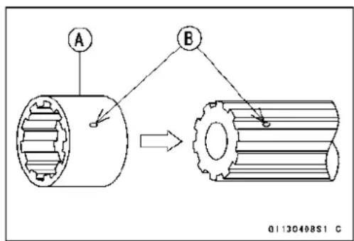

Transmission
- Thedriveshaftgearscanberecognizedbysize:thegear withthesmallestdiameteris1stgear,andthelargestone is6thgear.Besurethatallpartsareputbackinthecorrectsequenceandallcirclipsandwashersareproperlyin place.
- Installthe3rd/4thgearontothedriveshaftwiththeiroil holesaligned.
- Installthe6thgearbushingontothedriveshaftwiththeir oilholesaligned.
- Theoutputshaftgearscanberecognizedbysize:the gearwiththelargestdiameteris1stgear,andthesmall-estoneis6thgear.Besurethatallpartsareputback inthecorrectsequenceandallcirclipsandwashersare properlyinplace.
- Installthe5thand6thgearsontotheoutputshaftwith theiroilholesaligned.
- Installthe3rd/4thgearbushingsontotheoutputshaftwith theiroilholesaligned.
- Fitthesteelballsintothe5thgearholesintheoutput shaft, aligningthreeoilholes[D].
5thGear[A]
OutputShaft[B]
SteelBalls[C]
CAUTION
Donotapplygreasetotheballstoholdthemin place. This will cause the positiveneutralfinder mechanismtomalfunction.
Afterassembling the 5th gear with steel balls in place on the output shaft, check the ball-locking effect that the 5th geardoesn't come out of the output shaft when moving it up and down by hand.
- Checkthateachgearspinsorslidesfreelyonthetransmissionshaftswithoutbindingafterassembly.
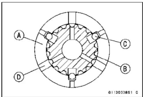
Transmission

1.1stGear
2.2ndGear
3.3rdGear
4.4thGear
5.5thGear
6.6th(Top)Gear
7.BallBearing
8.Bushing
9.ToothedWasher, φ34mm(1.34in.)
10.Circlip
11.Bushing
- ThrustWasher, 30mm(1.18in.)
13.NeedleBearing
14.Circlip
15.OilSeal
16.Collar
17.Washer
18.Nut
19.O-ring
20.Bearing
21.Spacer, φ39mm(1.54in.)
22.PositioningRing
23.Washer, φ40mm(1.57in.)
24.Bushing
25.ToothedWasher, φ38mm(1.50in.)
26.Shim, φ28mm(1.10in.)
27.SteelBall
28.Circlip, φ32.2mm(1.268in.)
29.ThrustWasher, φ25mm(0.98in.)
Transmission
ShiftDrumandForkRemoval
- Removethetransmissionassy(seeTransmissionAssyRemoval).
- Removetheshiftforks[A]andshiftdrumB.

ShiftDrumandForkInstallation
- RefertoTransmissionAssyAssemblyandInstallation.
ShiftDrumDisassembly
- RefertoTransmissionAssyRemovalandDisassembly.
ShiftDrumAssembly
- RefertoTransmissionAssemblyandInstallation.
ShiftForkBending
- Visuallyinspecttheshiftforks, and replaceanyforkthatis bent. Abentforkcouldcauseddifficultyinshifting, orallow thetransmissiontojumpoutofgearwhenunderpower. 90°[A]

ShiftFork/GearGrooveWear
- Measurethethicknessoftheshiftforkears[A], and measurethewidth[B]ofthegeargrooves.
★ Ifthethicknessofashiftforkearislessthantheservice limit, theshiftforkmustbereplaced.

ShiftForkEarThickness
Standard: 5.9 \~ 6.0 mm (0.232 \~ 0.236 in.)
ServiceLimit:5.8mm(0.228in.)
★ If the gear groove is worn over the service limit, the gear must bereplaced.
GearGrooveWidth
Standard: 6.05 \~ 6.15 mm (0.238 \~ 0.242 in.)
ServiceLimit:6.25mm(0.246in.)
Transmission
ShiftForkGuidePin/DrumGrooveWear
- Measurethediameterofeachshiftforkguidepin[A], and measurethewidth[B]ofeachshiftdrumgroove.
★ Iftheguidepinonanyshiftforkislessthantheservice limit, theforkmustbereplaced.
ShiftForkGuidePinDiameter
Standard: 6.9 \~ 7.0 mm (0.272 \~ 0.276 in.)
ServiceLimit:6.8mm(0.268in.)
★Ifanyshiftdrumgrooveiswornovertheservicelimit,the drummustbereplaced.
ShiftDrumGrooveWidth
Standard: 7.05 \~ 7.20 mm (0.278 \~ 0.283 in.)
ServiceLimit:7.3mm(0.287in.)
GearDogandGearDogHoleDamage
- Visuallyinspectthegeardogs[A]andgeardogholes[B].
★Replaceanydamagedgearsorgearswithexcessively worndogsordogholes.
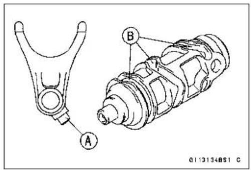

BallBearing, NeedleBearing, and Oil Seal
BallandNeedleBearingReplacement
CAUTION
Donotremovetheballorneedlebearingsunlessit isnecessary.Removalmaydamagethem.
- Usingapressorpuller,removetheballbearingand/or needlebearings.
NOTE
○Intheabsenceoftheabovementionedtools,satisfactoryresultsmaybeobtainedbyheatingthecasetoapproximately93°C(200°F)max.,andtappingthebearinginorout.
CAUTION
Donotheatthecasewithatorch. This will warp the case. Soakthecaseinoilandheattheoil.
- Usingapressandthebearingdriverset[A],installthe newballbearinguntilitstopsatthebottomofitshousing.
○Thenewneedlebearingsmustbepressedintothe crankcasesothattheendisflushwiththeendofthe hole.
SpecialTool-BearingDriverSet:57001-1129
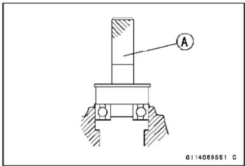
BallandNeedleBearingWear
CAUTION
Donotremovethebearingsforinspection. Removalmaydamagethem.
- Checktheballbearings.
○Sincetheballbearingsaremadetoextremelyclosetolerances,thewearmustbejudgedbyfeelratherthanmeasurement.Cleaneachbearinginahigh-flashpointsolvent,dryit(donotspinthebearingwhileitisdry),andoil itwithengineoil.
○Spin[A]thebearingbyhandtocheckitscondition.
★ If the bearing is noisy, does not spin smoothly, or has any rough spots, replace it.
- Checktheneedlebearings.
○Therollersinaneedlebearingnormallywearverylittle, andwearisdifficulttomeasure. Insteadofmeasuring, inspectthebearingforabrasion,colorchange, orother damage.
★ If there is any doubt to the condition of a needle bearing, replace it.

OilSealInspection
- Inspecttheoilseals.
★Replaceitifthelipsaremisshapen,discolored(indicating thattherubberhasdeteriorated),hardenedorotherwise damaged.
Wheels/Tires
TableofContents
Exploded View 10-2
Specifications 10-4
Special Tools 10-5
Wheels (Rims) 10-6
Front Wheel Removal 10-6
Front Wheel Installation 10-6
Rear Wheel Removal.... 10-8
Rear Wheel Installation.... 10-8
Wheel Inspection 10-10
Axle Inspection.... 10-10
Balance Inspection.... 10-11
Balance Adjustment.... 10-11
Balance Weight Removal.... 10-11
Balance Weight Installation.... 10-11
Tires.... 10-13
Air Pressure Inspection/Adjustment 10-13
Tire Inspection 10-13
Tire Removal 10-13
Tire Installation.... 10-13
Tire Repair 10-15
Hub Bearing.... 10-16
Hub Bearing Removal.... 10-16
Hub Bearing Installation.... 10-16
Hub Bearing Inspection.... 10-16
Hub Bearing Lubrication 10-17

ExplodedView
| No.Fastener | Torque | Remarks | ||
| N·mkgf | mft·lb | |||
| 1FrontAxle10811.080 | ||||
| 2FrontAxleClampBolt343.525 | ||||
| 3RearAxleNut10811.080 | ||||
G: Applygrease.
HG: Applyhigh-temperaturegrease.
R: ReplacementParts
WL: Applysoapandwatersolutionorrubberlubricant.
Specifications
| ItemStandardServiceLimit | ||
| Wheels(Rims)RimRunout:AxialTIR0.5mm(0.02in.)orlessTIR1.0mm(0.04in.)RadialTIR0.8mm(0.03in.)orlessTIR1.0mm(0.04in.)Axle Runout/100 mm (3.94 in.)WheelBalance10g(0.35oz.)orless——BalanceWeightsRimSize:Front17×3.50Rear | TIR 0.03 mm (0.0012 in.) or less——10g(0.35oz.),20g(0.71oz.),30g(1.06oz.)————17 × 4.50 | TIR 0.2 mm (0.008 in.)——— |
| TiresAirPressure(whenCold):FrontUpto180kg(397lb)load:225kPaRearTreadDepth:FrontRear | (2.25kgf/cm2,32psi)Upto180kg(397lb)load:250kPa(2.50kgf/cm2,36psi)6.5mm(0.26in.)9.0 mm (0.35 in.) | ———1mm(0.04 in.)(AT,CH,DE) 1.6mm(0.06in.)Up to 130 km/h (80 mph):2mm(0.08 in.)Over130km/h(80mph):3mm(0.12 in.) |
| Standard Tires:FrontDUNLOP,SPORTMAX RADIALRear | Make, Type | Size |
| D221FAJDUNLOP, SPORTMAX D221J | 120/70ZR17M/C(58W)160/60 ZR17 M/C (69 W) | |
AT: Austria
CH:Switzerland
DE:Germany
WARNING
Usethesamemanufacturer'stiresonbothfrontandrearwheels.
SpecialTools
BearingDriverSet: 57001-1129
natural_image
Isometric line drawing of a mechanical housing with multiple circular components and a central opening (no text or symbols)Jack: 57001-1238
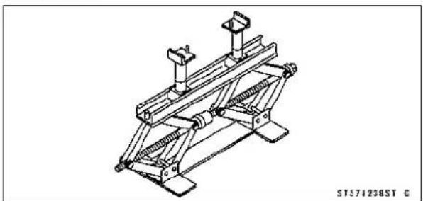
natural_image
Technical line drawing of a mechanical support structure (no text or symbols)BearingRemoverHead,20×22: φ 57001-1293

natural_image
Technical line drawing of a mechanical connector (no text or symbols)BearingRemoverShaft,13φ 57001-1377

natural_image
Line drawing of a long, elongated object with a pointed tip and textured end (no text or symbols)JackAttachment: 57001-1608
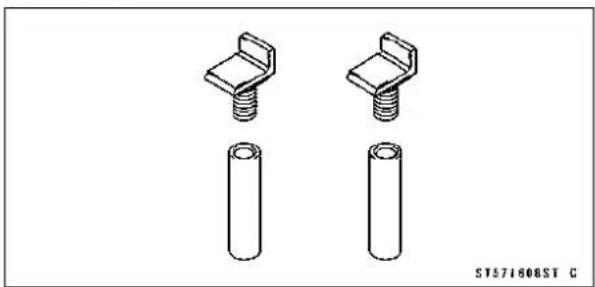
natural_image
Technical line drawing of two mechanical fasteners with cylindrical base (no text or symbols)Wheels(Rims)
FrontWheelRemoval
- Remove: BrakeCaliperMountingBolts[A] FrontBrakeCalipers[B]
- Loosen: AxleClampBolt[A] - Removethefrontaxle[B].
- Removethelowerfairing(seeLowerFairingRemovalin theFramechapter). - Raisethefrontwheeloffthegroundwithjack. SpecialTools-Jack:57001-1238 JackAttachment:57001-1608
- Pullouttheaxletotherightanddropthefrontwheelout oftheforks.
CAUTION
Donotlaythewheelonthegroundwiththediscs facingdown. This candamageorwarpthedisc. Placewoodenblocksunderthewheelsothatthe discdoesnottouchtheground.
FrontWheelInstallation
NOTE
○ Thedirectionofthewheelrotation[A]isshownbyan arrow[B]onthewheelspoke.
- Checkthewheelrotationmarkonthefrontwheeland installit.
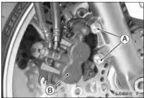

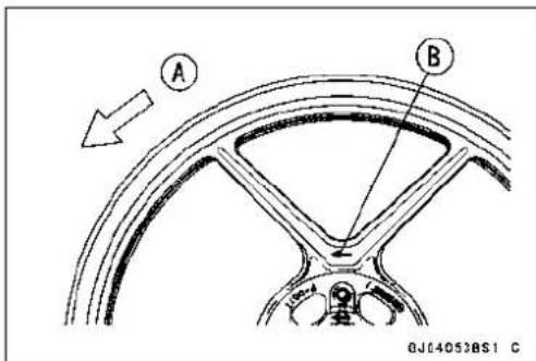
Wheels(Rims)
- Applyhigh-temperaturegreasetothegreaseseallips.
● Fitthecollars[A]onthebothsidesofthehub.
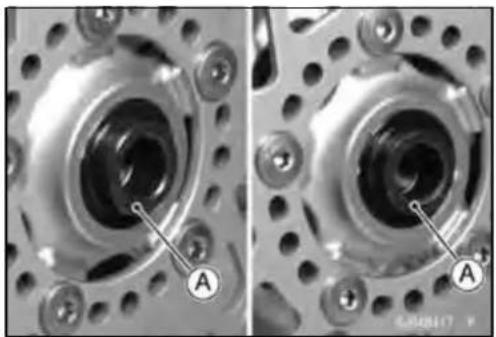
natural_image
Close-up of mechanical components with labeled parts A, showing internal circular features and bolted joints (no readable text or symbols)- Insertthefrontaxle, andtightentheaxle.
Torque-FrontAxle:108N·m(11.0kgf·m,80ft·lb) - Before tightening the axle clamp bolt on the right front fork leg, pump the front fork up and down 4 or 5 times to allow the right front fork leg to go on the front axle.
NOTE
○Putablockinfrontofthefrontwheeltostopmoving.
- Tightentheaxleclampbolt[A]. Torque-FrontAxleClampBolt:34N·m(3.5kgf·m,25ft·lb)

natural_image
Close-up of a car brake system with labeled components (no readable text or symbols)- Installthelowerfairing(seeLowerFairingInstallationin theFramechapter).
- Installthefrontbrakecalipers(seeCaliperInstallationin theBrakeschapter).
- Checkthefrontbrakeeffectiveness(seeBrakeOperationInspectioninthePeriodicMaintenancechapter).
WARNING
Donotattempttodrivethemotorcycleuntilafull brakeleverisobtainedbypumpingthebrakelever untilthepadsareagainstthedisc.Thebrakewill notfunctiononthefirstapplicationoftheleverif thisisnotdone.
10-8WHEELS/TIRES
Wheels(Rims)
RearWheelRemoval
- Raisetherearwheeloffthegroundwithstand[A].
- Remove:
BrakeCaliperMountingBolts[A] RearBrakeCaliper[B]
- Remove:
CotterPin[A]
AxleNut[B]
Washer[C]
Axle[D]withWasher
- Removethedrivechain[A]fromtherearsprockettoward theleft.
- Movetherearwheelbackandremoveit.
CAUTION
Donotlaythewheelonthegroundwiththedisc facingdown. This candamageorwarpthedisc. Placewoodenblocksunderthewheelsothatthe discdoesnottouchtheground.
RearWheelInstallation
- Applyhigh-temperaturegreasetothegreaseseallips.
- Fitthecollars[A]onthebothsidesofthehub.
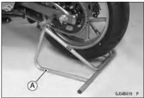
natural_image
Close-up of a motorcycle's wheel mounted on a metal platform, labeled with point A and GJ048419 P (no text or symbols on the object itself)


natural_image
Close-up mechanical assembly showing a gear and wheel with labeled component A (no readable text or symbols)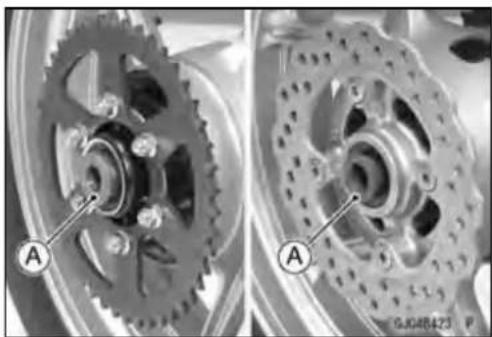
natural_image
Mechanical gear assembly diagram showing two views of a wheel with labeled components (no text or symbols present)Wheels(Rims)
- Engagethedrivechainwiththerearsprocket.
- Installthecaliperbracket[A]ontotheswingarmstop[B].
- Inserttheaxlefromtherightsideofthewheel, andtighten the axlenut.
Torque-RearAxleNut:108N·m(11.0kgf·m,80ft·lb)
- Insertanewcotterpin[A].
NOTE
When inserting the cotterpin, if the slots in thenut do not align with the cotterpinhole in the axle, tighten the nut clockwise [B] uptonextalignment.
○Itshouldbewithin30°.
○ Loosenonceandtightenagainwhentheslotgoespast thenaresthole.
- Bendthecotterpin[A]overthenut[B].
WARNING
Iftherearaxlenutisnotsecurelytightenedorthe cotterpinisnotinstalled,anunsaferidingconditionmayresult.
- Adjustthedrivechainslackafterinstallation(seeDriveChainSlackInspectioninthePeriodicMaintenancechapter).
- Installtherearbrakecaliper(seeCaliperInstallationin theBrakeschapter).
- Checktherearbrakeeffectiveness(seeBrakeOperationInspectioninthePeriodicMaintenancechapter).
WARNING
Donotattemptlodrivethemotorcycleuntilafull brakepedalisobtainedbypumpingthebrakepedal untilthepadsareagainstthedisc. Thebrakewill notfunctiononthefirstapplicationofthepedalif thisisnotdone.

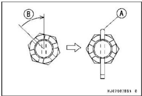

Wheels(Rims)
WheelInspection
- Raisethefront/rearwheeloffthegroundwithjack.
SpecialTools-Jack:57001-1238
JackAttachment:57001-1608
- Spinthewheellightly, and check for roughnessor binding.
★Ifroughnessorbindingisfound, replacethehubbearings. - Inspectthewheelforsmallcracks, dents, bending, or warp.
★Ifthereisanydamagetothewheel,replacethewheel. - Removethewheel, and support it without the tire by the axle.
- Measuretherimrunout, axial[A]andradial[B], withadial gauge.
★ Ifrimrunoutexceedstheservicelimit, checkthehubbearings.
★Iftheproblemisnotduetothebearings,replace the wheel.
RimRunout
Standard:
Axial TIR0.5mm(0.02in.)orless
Radial TIR0.8mm(0.03in.)orless
ServiceLimit:
Axial TIR1.0mm(0.04in.)
Radial TIR1.0mm(0.04in.)
WARNING
Neverattempttorepairadamagedwheel.Ifthere isanydamagebesideswheelbearings,thewheel mustbereplacedtoinsuresafeoperationalcondition.
AxleInspection
- Removethefrontandrearaxles(seeFront/RearWheelRemoval).
- Visuallyinspectthefrontandrearaxlefordamages.
★Iftheaxleisdamagedorbent,replaceit. - PlacetheaxleinVblocksthatare100mm(3.94in.)[A] apart, and set adial gauge[B] on the axle at a point halfway between the blocks. Turn[C] the axlet omea suretherunout. The difference between the highest and lowest dial readings sisthe amount of runout.
★Ifaxlerunoutexceedstheservicelimit,replacetheaxle.
AxleRunout/100mm(3.94in.)
Standard: TIR0.03mm(0.0012in.) or less
ServiceLimit: TIR0.2mm(0.008in.)


Wheels(Rims)
BalanceInspection
- Removethefrontandrearwheels(seeFront/RearWheel Removal).
- Supportthewheelsothatitcanbespunfreely.
- Spinthewheellightly, and mark[A]thewheelatthetop whentewheelstops.
○Repeatthisprocedureseveraltimes.Ifthewheelstopsofitsownaccordinvariouspositions,itiswellbalanced.
★ If the wheel always stops in one position, adjust the wheel balance (see Balance Adjustment).
BalanceAdjustment
- Ifthewheelalwaysstopsinoneposition,provisionally attachabalanceweight[A]ontherimatthemarkingusing adhesivetape.
- Rotatethewheel1/4turn[B], and seewhetherornotthe wheelstopsinthisposition. If it does, the correct balance weight is being used.
★ Ifthewheelrotatesandtheweightgoesup,replace the weightwiththenextheaviersize.Ifthewheelrotatesand theweightgoesdown,replace the weightwiththenext lightersize.Repeat these steps until the wheel remains at rest after being rotated 1/4 turn. - Rotatethewheelanother1/4turnandthenanother1/4turntoseeifthewheeliscorrectlybalanced.
- Repeat the entire procedure as many times necessary to achieve correct wheel balance.
- Permanentlyinstallthebalanceweight.
BalanceWeightRemoval
- Insertaregulartipscrewdrivers[A][B]betweentherib[C] andtheweight[D]asshown.
- Prythebalanceweightwithtwoscrewdriversandremove thebalanceweight.
- Discardtheusedbalanceweight.
CAUTION
Donottapthescrewdrivers.Therimcouldbedamaged.
BalanceWeightInstallation
- Checkiftheweightportionhasanyplayontheblade[A] andclip[B].
★ Ifitdoes, discardit.
WARNING
If the balance weight has any play on the rib of the rim, the blade and or clip have been stretched. Re placethelose balance weight. Donot reuse used balance weight. Unbalanced wheels can create an safer iding condition.
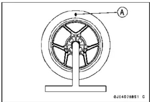

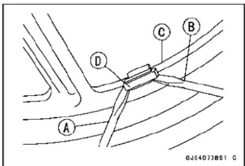

BalanceWeight
| PartNumberWeight | |
| 41075-000710g(0.35oz.) | |
| 41075-000820g(0.71oz.) | |
| 41075-000930g(1.06oz.) | |
NOTE
○ BalanceweightsareavailablefromKawasakidealersin 10,20,and30grams(0.35,0.71,and1.06oz.)sizes.Animbalanceoflessthan10grams(0.35oz.)willnot usuallyaffectrunningstability.
○ Donotusefourormorebalanceweight(morethan90 gram,3.17oz.). If the wheel requires an excess balance weight, disassemble the wheel to find the cause.
- Slipthebalanceweight[A]ontotherib[B]bypushingor lightlyhammering[C]theclip[D].
LeftSide[E] RightSide[F]

- Besuretoinstallthebalanceweight.
○Checkthattheblade[A]andclip[B]arefullyseatedontherim[C]andthattheclipishookedovertherib[D].
LeftSide[E] RightSide[F]

Tires
AirPressureInspection/Adjustment
- RefertotheAirPressureInspectioninthePeriodicMaintenancechapter.
TireInspection
- RefertotheWheel/TireDamageInspectioninthePeriodicMaintenancechapter.
TireRemoval
- Remove:
Wheel(seeFront/RearWheelRemoval) ValveCore(Letouttheair)
- Tomaintainwheelbalance, markthevalvestemposition onthetirewithchalksothatthetirecanbereinstalledin thesameposition.
ChalkMarkorYellowMark[A] AirValve[B] Align[C]
- Lubricatethetirebeadsandrimflangesonbothsideswith asoapandwatersolutionorrubberlubricant. This helps the tirebeadsslipofftherimflanges.
CAUTION
Neverlubricatewithengineoilorpetroleumdistillatesbecausetheywilldeterioratethetire.
- Removethetirefromtherimusingasuitablecommerciallyavailabletirechanger.
NOTE
○ Thetires cannot be removed with hand tools because they fit their imstootightly.
TireInstallation
WARNING
Usethesamemanufacturer'stiresonbothfrontand rearwheels.
- Inspecttherimandtire, andreplacethemifnecessary.
- Cleanthesealingsurfacesoftherimandtire, andsmooth the sealing surfaces of the rim with a fine emery cloth if necessary.
- Removetheairvalveanddiscardit.
CAUTION
Replacetheairvalvewheneverthetireisreplaced. Donotreusetheairvalve.

Tires
• Installanewvalveintherim.
- Removethevalvecap, lubricatethestemseal[A]witha soapandwatersolutionorrubberlubricant, andpull[B] thevalvestemthroughtherimfromtheinsideoutuntil snapsintoplace.
CAUTION
Donotuseengineoilorpetroleumdistillatestolubricatethestembecausetheywilldeterioratethe rubber.
○Theairvalveisshowninthefigure.
ValveCap[A]
ValveCore[B]
StemSeal[C]
ValveStem[D]
ValveSeat[E]
ValveOpened[F]
- Checkthetirerotationmarkonthefrontandreartiresand installthemontherimaccordingly.
TireRotationMark[A]
RotatingDirection[B]
- Positionthetireontherimsothatthevalve[A]alignwith thetirebalancemarkB.
- Install the tire bead over therim flange using as suitable commercially available tire changer.
- Lubricatethetirebeadsandrimflangeswithasopand watersolutionorrubberlubricanttohelpseathetire beadsinthesealingsurfacesoftherimwhileinflatingthe tire.
- Centertheriminthetirebeads, andinflatethetirewith compressedairuntilthetirebeadsseatinthesealing surfaces.
WARNING
Besuretoinstallthevalvecorewheneverinflating thetire, anddonotinflatethetiretomorethan400 kPa(4.0kgf/cm², 57psi). Overinflationcanexplode thetirewithpossibilityofinjuryandlossoflife.

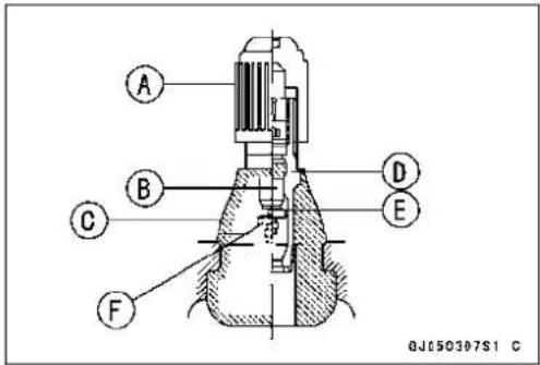


Tires
- Checktoseethatherimlines[A]onbothsidesofthetire sidewallsareparallelwiththerimflanges.
★ Iftherimflangesandtiresidewallrimlinesarenotparallel, removethevalvecore. - Lubricatetherimflangesandtirebeads.
- Installthevalvecoreandinflatethetireagain.
- Afterthetirebeadsseatintherimflanges, checkforair leakage.
○Inflatethetireslightlyabovestandardinflation.
OUseasoapandwatersolutionorsubmergethetire, and checkforbubblesthatwouldindicateleakage.
- Adjust the air pressure to the specified pressure (see Air Pressure Inspection in the Periodic Maintenance chapter).
- Installtheairvalvecap.
- Adjustthewheelbalance(seeBalanceAdjustment).
TireRepair
Currentlytwotypesofrepairfortubelesstireshavecome intowideuse.Onetypeiscalledatemporary(external)repairwhichcanbecarriedoutwithoutremovingthetirefrom therim,andtheothertypeiscalledpermanent(internal)repairwhichrequirestireremoval.Itisgenerallyunderstoodthathigherrunningdurabilityisobtainedbypermanent(internal)repairsthanbytemporary(external)ones. Also,permanent(internal)repairshavetheadvantageof permittingathoroughexaminationforsecondarydamage notvisiblefromexternalinspectionofthetire.Forthese reasons,Kawasakidoesnotrecommendtemporary(external)repair.Onlyappropriatepermanent(internal)repairs arerecommended.Repairmethodsmayvaryslightlyfrom maketomake.Followtherepairmethodsindicatedbythe manufactureroftherepairtoolsandmaterialssothatsafe resultscanbeobtained.

HubBearing
HubBearingRemoval
- Removethewheel(seeFront/RearWheelRemoval), and takeoutthefollowing.
Collars
Coupling(Outofrearhub)
GreaseSeals
- Usethebearingremovertoremovethehubbearings[A].
CAUTION
Donotlaythewheelonthegroundwiththedisc facingdown. This candamageorwarpthedisc. Placewoodenblocksunderthewheelsothatthe discdoesnottouchtheground.
SpecialTools-BearingRemoverHead,20×22[B]: 57001-1293
BearingRemoverShaft, 13[C] :57001-1377
HubBearingInstallation
- Beforeinstallingthehubbearings,blowanydirtorforeign particlesoutofthehubwithcompressedairtoprevent contaminationofthebearings.
- Replacethebearingswithnewones.
NOTE
○ Installthebearingssothatthemarkedsidefacesout.
- Installthebearingsbyusingthebearingdriversetwhich doesnotcontactthebearinginnerrace.
- Pressineachbearing[A]rightuntiltheyarebottomed.
SpecialTool-BearingDriverSet[B]:57001-1129
- Replacethegreasesealswithnewones.
- Pressinthegreaseseals[A]sothatthesealsurfaceis flush[B] withtheend ofthe hole.
○Applyhigh-temperaturegreasetothegreaseseallips.
SpecialTool-BearingDriverSet[C]:57001-1129
HubBearing Inspection
Since the hub bearings are made to extremely close tolerances, the clearance cannot normally be measured.
NOTE
○ Donotremoveanybearingsforinspection. Ifanybearingsareremoved, they will need to be replaced with new ones.
- Turneach bearinginthehubbackandforth[A]while checkingforplays,roughnessorbinding.
★Ifbearingplay,roughnessorbindingisfound,replacethe bearing. - Examinethebearingseal[B]fortearsorleakage.
★Ifthesealistornorisleaking,replacethebearing.

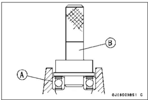
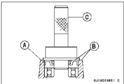

HubBearing
HubBearingLubrication
NOTE
○Sincethehubbearingsarepackedwithgreaseand sealed,lubricationisnotrequired.
FinalDrive
TableofContents
Exploded View.... 11-2
Specifications 11-4
Special Tools 11-5
Drive Chain.... 11-6
Drive Chain Slack Inspection 11-6
Drive Chain Slack Adjustment 11-6
WheelAlignmentInspection/Adjustment....11-6
Drive Chain Wear Inspection 11-6
Drive Chain Lubrication.... 11-6
Drive Chain Removal 11-6
Drive Chain Installation 11-7
Sprocket, Coupling 11-10
Engine Sprocket Removal 11-10
Engine Sprocket Installation 11-11
Rear Sprocket Removal.... 11-11
Rear Sprocket Installation.... 11-11
Coupling Installation.... 11-12
Coupling Bearing Removal 11-12
Coupling Bearing Installation 11-12
Coupling Bearing Inspection 11-13
Coupling Bearing Lubrication.... 11-13
Coupling Damper Inspection.... 11-13
Sprocket Wear Inspection.... 11-13
Rear Sprocket Warp Inspection 11-14

GK02088B75 C
ExplodedView
| No.Fastener | Torque | Remarks | |||
| N·mkgf | mft·lb | ||||
| 1 | Engine Sprocket Nut | 125 | 12.7 | 92 | MO |
| 2RearAxleNut10811.080 | |||||
| 3 | Rear Sprocket Nuts | 59 | 6.0 | 44 | |
| 4 | Speed Sensor Bolt | 7.8 | 0.80 | 69 in·lb | L |
| 5 | Speed Sensor Bracket Bolts | 9.8 | 1.0 | 87 in·lb | |
G: Applygrease.
HG: Applyhigh-temperature grease.
HO: Apply heavyoil.
L: Applya non-permanentlockingagent.
MO: Applymolybdenumdisulfide oilsolution.
(mixture of the engine oil and molybdenum disulfide grease in a weight ratio 10 : 1)
R: Replacement Parts
Specifications
| ItemStandardServiceLimit | ||
| DriveChain | ||
| Drive Chain Slack | 30 ~ 40 mm (1.2 ~ 1.6 in.) | -- -- |
| Drive Chain Wear (20-link Length) | 317.5 ~ 318.2 mm (12.50 ~ 12.53 in.) | 323 mm (12.7 in.) |
| StandardChain: | ||
| MakeENUMA-- -- | ||
| TypeEK520MVXL1-- -- | ||
| Link | 114 links | -- -- |
| Sprockets | ||
| Rear Sprocket Warp | 0.4 mm (0.016 in.) or less | 0.5 mm (0.020 in.) |
SpecialTools
InsideCirclipPliers: 57001-143
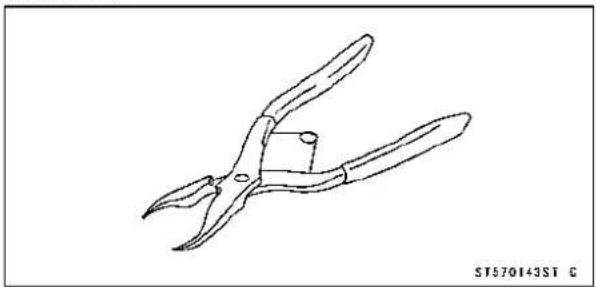
natural_image
Line drawing of a pair of pliers (no text or symbols)BearingDriverSet: 57001-1129
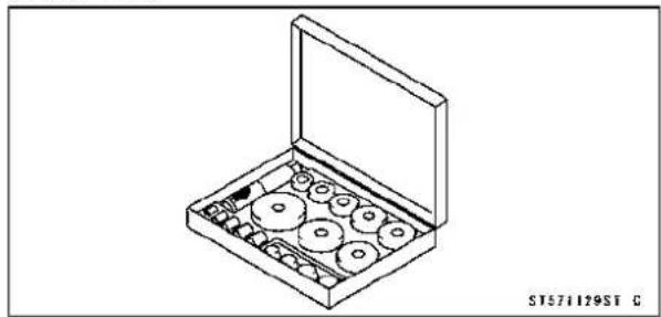
natural_image
Isometric line drawing of a box containing multiple circular components, no text or symbols presentDriveChain
DriveChainSlackInspection
- RefertotheDriveChainSlackInspectioninthePeriodic Maintenancechapter.
DriveChainSlackAdjustment
- RefertotheDriveChainSlackAdjustmentinthePeriodic Maintenancechapter.
WheelAlignmentInspection/Adjustment
- RefertotheWheelAlignmentInspectioninthePeriodic Maintenancechapter.
DriveChainWearInspection
- RefertotheDriveChainWearInspectioninthePeriodic Maintenancechapter.
DriveChainLubrication
- RefertotheDriveChainLubricationConditionInspection inthePeriodicMaintenancechapter.
DriveChainRemoval
NOTE
○ Sincethedrivechainisinstalledthroughtheswingarm, thechaincannotberemovedotherthanbycuttingit. Preparethenewlinkpin, linkplate, greaseseals, and toolsforrejoiningthechain.
- Usingasuitabletool, cutthedrivechainbyremovingthe linkpins.
RecommendedTool: EKJointTool#50
CAUTION
ReadtheToolManualbeforeremoving.
Body[A]
Handlebar[B]
CuttingandRivetingPin[C]
ForCutting[D]
ForRiveting[E]
PlateHolder(a)[F]
PlateHolder(b)[G]
Gauge[H]
- Grind[A]thepinheadtomakeitflat.
- Setthecuttingandrivetingpin[B]asshown.
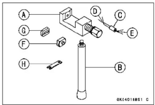

DriveChain
- Screwthepinholderuntilittoucheschainpin.
-
Besurethatthecuttingpinhitscenterofchainpin.
-
Screwthehandlebar[A]intobody.
- Turnthepinholderwithwrench[B]clockwisetoextract chainpin.

natural_image
Technical line drawing of a mechanical assembly with rollers and a shaft, showing a curved arrow indicating motion (no text or symbols)
DriveChainInstallation
- Engagethenewdrivechaintotheolddrivechainandpull theendoftheolddrivechainuntiltheyarechangingthe position.
- Removetheolddrivechainfromthenewdrivechain.
- Applygreasetothelinkpins[A]andgreaseseals[B][C].
- Engagethedrivechainontherearsprocketthroughthe swingarm.
- Insertthelinkpinsinthedrivechainends.
• Installthegreaseseals[C].
• Installthelinkplatesothatthemark[D]facesout. - Pushthelinkplatebyhandorpliertofixit.
- Incaseofgreasesealchain,besuretosetthegrease sealscorrectly.
- Settheplateholder(a)[A]andplateholder(b)[B]onthe body.


11-8FINALDRIVE
DriveChain
- Fittheplateholder(a)tolinkplate.
-
Turnthepinholderbyhanduntilplateholder(b)touches theotherlinkplate.
-
Turnthepinholderbywrenchclockwiseuntiltwopinsof linkcomeintogrooveofplateholder(a).
• Takeofftheplateholder(a).
- Settheplateholder(b)[A]andcuttingandrivetingpin[B]asshown.
- Turnthepinholderuntilrivetingpintoucheslinkpin.
- Turnthewrenchclockwiseuntiltipofrivetingpinhitsof linkpin.
• Rivetit. - Sameworkfortheotherlinkpin.

natural_image
Mechanical assembly diagram showing a rotating shaft and chain mechanism (no text or symbols)
natural_image
Technical line drawing of a mechanical assembly with no visible text or symbols

natural_image
Technical line drawing of a mechanical assembly with rotating shaft and housing (no text or symbols)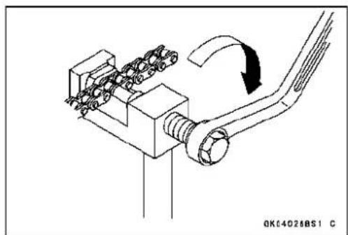
natural_image
Technical line drawing of a mechanical assembly with spring-loaded components and a curved arrow indicating rotation (no text or symbols)DriveChain
- Afterstaking, checkthestakedareaofthelinkpinfor cracks.
- Measuretheoutsidediameter[A]ofthelinkpinandlink plateswidth[B].
LinkPinOutsideDiameter
Standard: 5.7 \~ 6.0 mm (0.22 \~ 0.24 in.)
LinkPlatesOutsideWidth
Standard: 17.25 \~ 17.45 mm (0.679 \~ 0.687 in.)
★ If thereading exceed sthespecified length, cut andrejoin thechain again.
- Check:
MovementoftheRollers
- Adjustthedrivechainsslackafterinstallingthechain(see DriveChainSlackAdjustmentinthePeriodicMaintenancechapter).

11-10FINALDRIVE
Sprocket, Coupling
EngineSprocketRemoval
- Remove: EngineSprocketCoverBolts[A] EngineSprocketCover[B]
- Remove: SpeedSensorBracketBolts[A] SpeedSensorBracket[B]
- Flattenoutthebendedwasher[A]. - Removetheenginesprocketnut[B]andwasher.
NOTE
○ Whenlooseningtheenginesprocketnut, holdtherear brakeon.
- Raisetherearwheeloffthegroundwithstand.
- Removetheaxlecotterpin, and loosentherearaxlenut.
- Loosenthedrivechain(seeDriveChainSlackAdjustmentinthePeriodicMaintenancechapter).
- Removethedrivechainfromtherearsprockettowardthe right.
- Pulltheenginesprocket[A]withdrivechain[B]offthe outputshaft[C].
- Disengagethedrivechainfromtheenginesprocket.
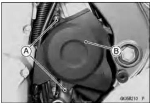
natural_image
Mechanical component diagram showing a central circular component with labeled points A and B, surrounded by springs and gears (no readable text or symbols)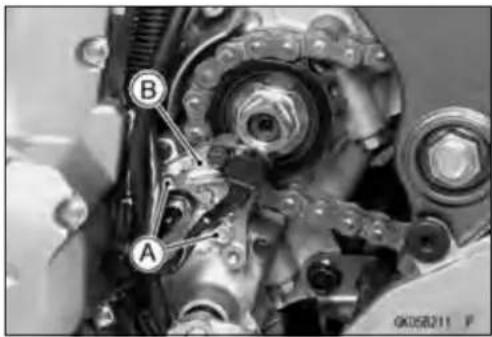
natural_image
Mechanical gear assembly with labeled components A and B (no readable text or symbols beyond labels)

Sprocket, Coupling
EngineSprocketInstallation
- Replacethesprocketwasherandaxlecotterpin.
- Installtheenginesprocket[A]sothat"OUTSIDE"letters faceoutward.
- Applymolybdenumdisulfideoilsolutiontothethreads oftheoutputshaftandseatingsurfaceoftheengine sprocketnut.
- Aftertorquingtheenginesprocketnut,bendtheoneside ofthewasher[B]overthenut.
NOTE
○ Tightentheenginesprocketnutwhileapplyingtherear brake.
- Tighten:
Torque-EngineSprocketNut:125N·m(12.7kgf·m,92ft·lb) SpeedSensorBracketBolts:9.8N·m(1.0kgf·m, 87in·lb)
- Installtheenginesprocketcover, andtightenthebolts.
- Adjustthedrivechainslackafterinstallingthesprocket (seeDriveChainSlackAdjustmentinthePeriodicMaintenancechapter).
- Bendtheendofaxlecotterpinsurelyaftertighteningthe axlenut(seeRearWheelInstallationintheWheels/Tires chapter).
RearSprocketRemoval
- Removetherearwheel(seeRearWheelRemovalinthe Wheels/Tireschapter).
CAUTION
Donotlaythewheelonthegroundwiththedisc facingdown. This candamageorwarpthedisc. Placewoodenblocksunderthewheelsothatthe discdoesnottouchtheground.
- Removetherearsprocketnuts[A].
- Removetherearsprocket[B].
RearSprocketInstallation
- Installthesprocketfacingthetoothnumbermarking[A] outward.
- Tightentherearsprocketnuts. Torque-RearSprocketNuts:59N·m(6.0kgf·m,44ft·lb)
- Installtherearwheel(seeRearWheelInstallationinthe Wheels/Tireschapter).
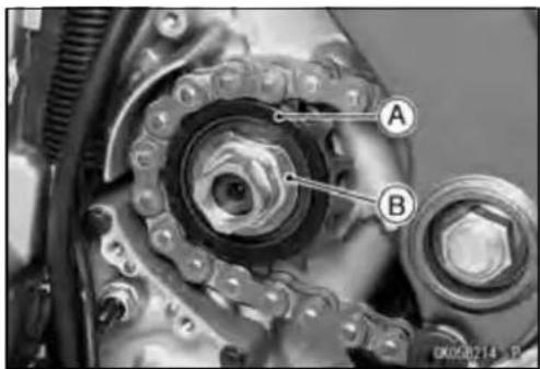

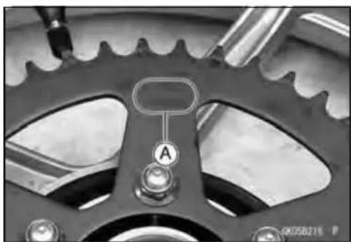
natural_image
Close-up of a mechanical gear with visible teeth and central knob (no text or symbols)11-12FINALDRIVE
Sprocket, Coupling
Coupling Installation
- Applyhigh-temperaturegreasetothecouplinggrease seallips[A].
-
Applygreasetothecouplinginternalsurface[B].
-
Greasethefollowing. WheelFlangePortion[A] O-ring[B]
• Installthecollar[C].
CouplingBearingRemoval
- Remove:
Coupling
GreaseSeal
Circlip[A]
SpecialTool-InsideCirclipPliers:57001-143
- Removethebearing[A]bytappingfromthewheelside.
SpecialTool-BearingDriverSet[B]:57001-1129
CouplingBearingInstallation
- Replacethebearingwithanewone.
- Pressinthebearing[A]untilitisbottomed.
SpecialTool-BearingDriverSet[B]:57001-1129 - Replacethecirclipwithanewone.
SpecialTool-InsideCirclipPliers:57001-143


natural_image
Close-up of a mechanical component with a central circular bore and bolt holes (no visible text or symbols)

Sprocket, Coupling
- Replacethegreasesealwithanewone.
- Pressinthegreasesealsothatthesealsurfaceisflush withtheendofthehole.
○Applyhigh-temperaturegreasetothegreaseseallips.
SpecialTool-BearingDriverSet:57001-1129
CouplingBearingInspection
Sincethecouplingbearingismadetoextremelyclose tolerances, the clearance cannot normally be measured.
NOTE
- Itisnotnecessarytoremovethecouplingbearingfor inspection. Ifthebearingisremoved, itwillneedtobe replacedwithanewone.
- Turnthebearinginthecouplingbackandforth[A]while checkingforplays,roughnessorbinding.
★ If the bearing play, roughnessor binding is found, replace the bearing. - Examinethebearingseal[B]fortearsorleakage.
★ Ifthesealistornorisleaking, replacethebearing.
CouplingBearingLubrication
NOTE
○Sincethecouplingbearingispackedwithgreaseand sealed,lubricationisnotrequired.
CouplingDamperInspection
- Removetherearwheelcoupling, and inspecttherubber dampers[A].
- Replacethedamperifitappearsdamagedordeteriorated.
SprocketWearInspection
- Visually inspect the engine and rears procketteeth for wear and damage.
★ Iftheteetharewornasillustrated, replacethesprocket, and inspect the drivechainwear (seeDriveChainWear Inspection in the Periodic Maintenance chapter). WornTooth (Engine Sprocket) [A] WornTooth (Rear Sprocket) [B] Direction of Rotation [C]
NOTE
○ Ifasprocketrequiresreplacement,thechainisprobablywornalso.Whenreplacingasprocket,inspectthe chain.
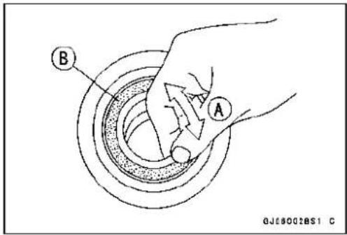

natural_image
Close-up of a mechanical component with central hub and mounting holes (no visible text or symbols)
RearSprocketWarpInspection
- Raisetherearwheeloffthegroundwithstandsothatit willturnfreely.
- Setadialgauge[A]againsttherearsprocket[B]nearthe teethasshown,androtate[C]therearwheeltomeasure thesprocketrunout(warp). Thedifferencebetween the highestandlowestdialgaugereadingsistheamountof runout(warp).
★Iftherunoutexceedstheservicelimit,replacetherear sprocket.
RearSprocketWarp
Standard:0.4mm(0.016in.)orless
ServiceLimit:0.5mm(0.020in.)
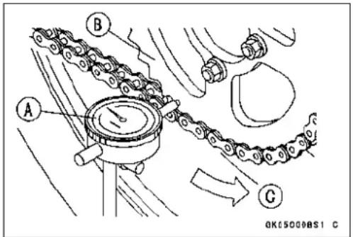
Brakes
TableofContents
ExplodedView....12-2
Specifications....12-6
SpecialTools....12-7
BrakeLever, BrakePedal....12-8
BrakeLeverPositionAdjustment.12-8
BrakePedalPositionInspection..12-8
BrakePedalPositionAdjustment.12-8
BrakePedalRemoval....12-9
BrakePedallInstallation....12-9
Calipers....12-11
FrontCaliperRemoval....12-11
RearCaliperRemoval......12-11
CaliperInstallation....12-11
FrontCaliperDisassembly......12-12
FrontCaliperAssembly....12-12
RearCaliperDisassembly......12-12
RearCaliperAssembly....12-12
CaliperFluidSealDamage......12-12
RearCaliperDustBootand FrictionBootDamage....12-12
CaliperPistonandCylinder Damage....12-13
RearCaliperHolderShaftWear..12-13
BrakePads.... 12-14
FrontBrakePadRemoval......12-14
FrontBrakePadInstallation......12-14
RearBrakePadRemoval...... 12-14
RearBrakePadInstallation...... 12-14
BrakePadWearInspection......12-14
MasterCylinder.... 12-15
FrontMasterCylinderRemoval...12-15
FrontMasterCylinderInstallation 12-15
RearMasterCylinderRemoval.... 12-16
RearMasterCylinderInstallation.12-16
FrontMasterCylinder Disassembly.....12-16
RearMasterCylinder Disassembly.....12-16
MasterCylinderAssembly...... 12-16
MasterCylinderInspection......12-17
BrakeDisc.... 12-18
BrakeDiscRemoval....12-18
BrakeDisclInstallation....12-18
BrakeDiscWear.... 12-18
Brake Disc Warp 12-18
BrakeFluid.... 12-19
BrakeFluidLevelInspection...... 12-19
BrakeFluidChange.... 12-19
BrakeLineBleeding......12-19
BrakeHose.... 12-22
BrakeHoseRemoval/Installation.12-22
BrakeHoseInspection......12-22

ExplodedView
| No. | Fastener | Torque | Remarks | ||
| N·mkgf | f·mft·lb | ||||
| 1 | BleedValve7.80.8069in·lb | ||||
| 2 | BrakeHoseBanjoBolts252.518 | ||||
| 3 | Brake Lever Pivot Bolt | 1.0 | 0.10 | 9 in·lb | Si |
| 4 | Brake Lever Pivot Bolt Locknut | 5.9 | 0.60 | 52 in·lb | |
| 5 | Front Brake Disc Mounting Bolts | 27 | 2.8 | 20 | L |
| 6 | Front Brake Light Switch Screw | 1.0 | 0.10 | 9 in·lb | |
| 7 | FrontBrakeReservoirCapScrews | 1.0 | 0.10 | 9 in·lb | |
| 8 | Front Caliper Mounting Bolts | 34 | 3.5 | 25 | |
| 9 | Front Master Cylinder Clamp Bolts | 8.8 | 0.90 | 78 in·lb | S |
B: Applybrakefluid.
L: Applyanon-permanentlockingagent.
R: ReplacementParts
S: Followthespecifiedtighteningsequence.
Si: Applysiliconegrease(ex. PBCgrease).

ExplodedView
| No.Fastener | Torque | Remarks | |||
| N·mkgf | ·mft·lb | ||||
| 1BleedValve7.80.8069in·lb | |||||
| 2BrakeHoseBanjoBolts252.518 | |||||
| 3BrakePedalBolt8.80.9078in·lb | |||||
| 4 | Rear Brake Disc Mounting Bolts | 27 | 2.8 | 20 | L |
| 5 | Rear Caliper Mounting Bolts | 25 | 2.5 | 18 | |
| 6 | Rear Master Cylinder Mounting Bolts | 25 | 2.5 | 18 | |
| 7 | RearMasterCylinder Push RodLocknut | 181.8 | 3 | ||
B: Applybrakefluid.
G: Applygrease.
L: Applyanon-permanent lockingagent.
R: ReplacementParts
Si: Apply silicone grease (ex. PBC grease).
Specifications
| ItemStandardServiceLimit | ||
| BrakeLever,BrakePedalBrakeLeverPosition5-wayadjustable(tosuitrider)-- --BrakeLeverFreePlayNon-adjustable-- --PedalFreePlayNon-adjustable-- --PedalPositionAbout40mm(1.6in.)belowtopoffootpeg-- -- | ||
| BrakePadsLiningThickness:FrontRear | 4.5mm(0.18in.)1mm(0.04in.)5.0mm(0.20in.)1mm(0.04in.) | |
| BrakeDiscThickness:FrontRearRunout | 4.3 ~ 4.7 mm (0.17 ~ 0.19 in.)4.8 ~ 5.2 mm (0.19 ~ 0.20 in.)0.15 mm (0.006 in.) or less | 4.0 mm (0.16 in.)4.5 mm (0.18 in.)0.3 mm (0.01 in.) |
| BrakeFluidGrade | DOT4 | -- -- |
SpecialTools
InsideCirclipPliers: 57001-143
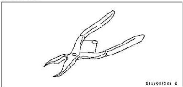
natural_image
Line drawing of a pair of pliers (no text or symbols)Jack: 57001-1238
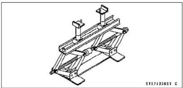
natural_image
Technical line drawing of a mechanical support structure (no text or symbols)JackAttachment: 57001-1608

natural_image
Technical line drawing of two mechanical fasteners with cylindrical base (no text or symbols)12-8BRAKES
BrakeLever, BrakePedal
BrakeLeverPositionAdjustment
Thebrakeleveradjusterhas5positionssothatthebrake leverpositioncanbeadjustedtosuittheoperator'shand.
- Pushtheleverforwardandturntheadjuster[A]toalign thenumberwiththearrowmark[B]ontheleverholder.
○The distance from the griptotheleveris minimum at number 5 and maximum at number 1.
BrakePedalPositionInspection
- Check that the brake pedal [A] is in the correct position. Footpeg [B]
PedalPosition
Standard: About40mm(1.6in.)[C]belowtopof footpeg
★Ifitisincorrect,adjustthebrakepedalposition.
BrakePedalPositionAdjustment
NOTE
○ Usuallyitisnotnecessarytoadjustthepedalposition, butalwaysadjustitwhenthepushrodlocknuthasbeen loosened.
- Remove:
FrameCover(seeFrameCoverRemovalintheFrame chapter) Bolts[A] RightFootpegStay[B]
- Loosenthelocknut[A]andturnthepushrodwiththehex head[B]toachievethecorrectpedalposition.
★Ifthelength[C]shownis70±1mm(2.76±0.04in.), the pedalpositionwillbewithinthestandardrange.
- Tighten:
- Loosenthelocknut[A]andturnthepushrodwiththehex head[B]toachievethecorrectpedalposition. ★Ifthelength[C]shownis70±1mm(2.76±0.04in.), the pedalpositionwillbewithinthestandardrange. ● Tighten:
Torque-RearMasterCylinderPushRodLocknut:18N·m (1.8kgf·m, 13ft·lb)
• Installthefootpegstay, andtightenthebolts.
Torque - Footpeg Stay Bolts: 34 N·m (3.5 kgf·m, 25 ft·lb)
- Checkthebrakelightswitchoperation(seeBrakeLight SwitchOperationInspectioninthePeriodicMaintenance chapter).


natural_image
Mechanical assembly diagram showing labeled components A and B (no readable text or symbols beyond labels)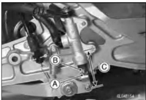
BrakeLever, BrakePedal
BrakePedalRemoval
- Remove:
FrameCover(seeFrameCoverRemovalintheFrame chapter) Bolts[A] RightFootpegStay[B]
- Remove:
CotterPin[A] JointPin[B] RearBrakeLightSwitchSpring[C] ReturnSpring[D]
- Removethemountingbolt[E]andtakeoutthebrake pedal.
BrakePedallInstallation
- Applygreasetothepivotshaft[A]andinstallthewasher [B].
- Install:
BrakePedal[C] Washer[D] BrakePedalBolt[E]
Torque-BrakePedalBolt:8.8N·m(0.90kgf·m,78in·lb)
- Hookthelowerendoftherearbrakelightswitchspring [A]onthepedalhook.
-
Hooktheupperendofthereturnspring[B]onthepedal hook.
-
Replacethecotterpinwithanewone.
- Insertthecotterpin[A]andbendthepinends[B].

natural_image
Mechanical assembly diagram showing labeled components A and B (no readable text or symbols beyond labels)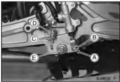

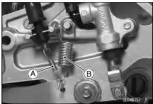
natural_image
Mechanical assembly diagram showing two labeled components (A and B) with no readable text or symbols
12-10BRAKES
BrakeLever, BrakePedal
• Installtherightfootpegstay, andtightenthebolts.
Torque-FootpegStayBolts:34N·m(3.5kgf·m,25ft·lb)
○Depressthebrakepedal[A]andthenaligntheboltsholes ofthemastercylinder[B].
Torque-RearMasterCylinderMountingBolts:25N·m(2.5 kgf·m,18ft·lb)
- Checkthebrakepedalposition(seeBrakePedalPosition Inspection).
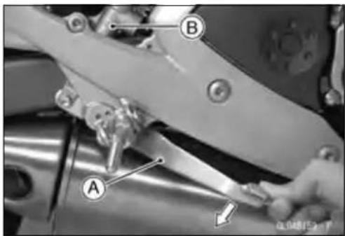
Calipers
FrontCaliperRemoval
- Loosenthebanjobolt[A]atthebrakehoselowerend, andtightenitloosely.
- Unscrewthecalipermountingbolts[B], and detach the caliper[C] fromthedisc.
- Unscrewthebanjoboltandremovethebrakehoses[D] fromthecaliper(seeBrakeHoseRemoval/Installation).
CAUTION
Immediatelywashawayanybrakefluidthatspills.

NOTE
○Ifthecaliperistobedisassembledafterremovalandif compressedairisnotavailable,disassemblethecaliper beforethebrakehoseisremoved(seeFrontCaliper Disassembly).
RearCaliperRemoval
- Loosenthebanjobolt[A]atthebrakehoselowerend, andtightenitloosely.
- Unscrewthecalipermountingbolts[B], and detach the caliper[C] fromthedisc.
- Unscrewthebanjoboltandremovethebrakehose[D] fromthecaliper(seeBrakeHoseRemoval/Installation).
CAUTION
Immediatelywashawayanybrakefluidthatspills.
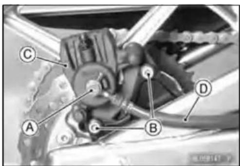
NOTE
○ Ifthecaliperistobedisassembledafterremovalandif compressedairisnotavailable,disassemblethecaliper beforethebrakehoseisremoved(seeRearCaliper Disassembly).
CaliperInstallation
• Installthecaliperandbrakehoselowerend.
○Replacethewashersoneachsideofhosefittingwithnew ones.
- Tighten:
Torque-CaliperMountingBolts
Front:34N·m(3.5kgf·m,25ft·lb)
Rear:25N·m(2.5kgf·m,18ft·lb)
BrakeHoseBanjoBolts:25N·m(2.5kgf·m,18ft·lb)
- Checkthefluidlevelinthebrakereservoirs.
- Bleedthebrakeline(seeBrakeLineBleeding).
- Checkthebrakeforgoodbrakingpower,nobrakedrag, andnofluidleakage.
WARNING
Donotattempttodrivethemotorcycleuntilafull brakeleverorpedalisobtainedbypumpingthe brakeleverorpedaluntilthepadsareagainstthe disc. Thebrakeswillnotfunctiononthefirstapplicationoftheleverorpedalifthisisnotdone.
Calipers
FrontCaliperDisassembly
- RefertotheCaliperRubberPartsReplacementinthePeriodicMaintenancechapter.
FrontCaliperAssembly
- RefertotheCaliperRubberPartsReplacementinthePeriodicMaintenancechapter.
RearCaliperDisassembly
- RefertotheCaliperRubberPartsReplacementinthePeriodicMaintenancechapter.
RearCaliperAssembly
- RefertotheCaliperRubberPartsReplacementinthePeriodicMaintenancechapter.
CaliperFluidSealDamage
Thefluidseal(pistonseal)[A]isplacedaroundthepistontomaintainclearancebetweenthepadandthedisc.If thesealisinapoorcondition,itcouldleadthepadtowear excessivelyorthebraketodrag,whichmaycausethetemperatureofthediscsorthebrakefluidtoincrease.
- Replacethefluidsealifitexhibitsanyoftheconditions listedbelow.
○Brakefluidleakagearoundthepad.
○Brakesoverheat.
○Considerabledifferenceininnerandouterpadwear.
○Sealandpistonarestucktogether.
★Ifthefluidsealisreplaced, replacethedustseal[B]as well. Also, replaceallsealseveryothertimethepadsare changed.
RearCaliperDustBootandFrictionBootDamage
- Check that the dustboot[A] and frictionboot[B] are not cracked, worn, swollen, or other wisedamaged.
★Iftheyshowanydamage,replaceit.


Calipers
CaliperPistonandCylinderDamage
- Visuallyinspectthepistons[A]andcylindersurfaces[B].
★Replacethecaliperifthecylinderandpistonarebadly scoresorrusty.

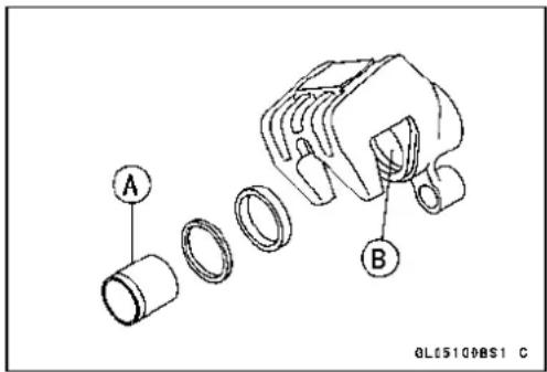
RearCaliperHolderShaftWear
Thecaliperbodymustslidessmoothlyonthecaliperholder shafts[A].Ifthebodydoesnotslidessmoothly,onepadwill wearmorethantheother,padwearwillincrease,andconstantdragonthediscwillraisebrakeandbrakefluidtemperature.
- Checktoseethatthecaliperholdershaftsarenotbadly wornorstepped, and thattherubberfrictionbootsarenot damaged.
★ Iftherubberfrictionbootisdamaged, replacetherubber frictionboot. Toreplacethefrictionboot, removethepads and thecaliperbracket.
★ Ifthecaliperholdershaftisdamage, replacothecaliper bracket.

BrakePads
FrontBrakePadRemoval
- Removethefrontcaliperwiththehoseinstalled(seeFront CaliperRemoval).
- Drawouttheholdershaftpin[A], andtakeofftheholder shaft[B].
- Removethepad[C]onthepistonside.
- Pushtheholder[D]towardsthepiston,andremovethe padoftheotherside[E]fromtheholdershaft[F].
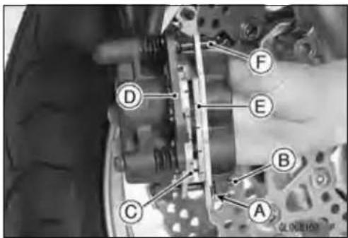
FrontBrakePadInstallation
- Pushthecaliperpistonsinbyhandasfarastheywillgo.
• Installtheanti-rattlespringinitscorrectposition. - Installthepadonthepistonsidefirst, then installtheother padontheholder.
- Installthefrontcaliper(seeCaliperInstallation).
WARNING
Donotattempttodrivethemotorcycleuntilafull brakeleverisobtainedbypumpingthebrakelever untilthepadsareagainstthedisc.Thebrakewill notfunctiononthefirstapplicationoftheleverif thisisnotdone.
RearBrakePadRemoval
- Removetherearcaliperwiththehoseinstalled(seeRear CaliperRemoval).
- Drawouttheholdershaftpin[A], and takeofftheholder shaft[B].
- Removethepad[C]onthepistonside.
- Pushtheholder[D]towardsthepiston,andremovethe padoftheotherside[E]fromtheholdershaft[F].
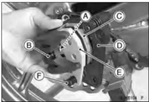
RearBrakePadInstallation
- Pushthecaliperpistoninbyhandasfarasitwillgo.
• Installtheanti-rattlespringinitscorrectposition. - Installthepadonthepistonsidefirst, theninstalltheother padontheholder.
- Installtherearcaliper(seeCaliperInstallation).
WARNING
Donotattemptlodrivethemotorcycleuntilafull brakepedalisobtainedbypumpingthebrakepedal untilthepadsareagainstthedisc. Thebrakewill notfunctiononthefirstapplicationofthepedalif thisisnotdone.
BrakePadWearInspection
- RefertotheBrakePadWearInspectioninthePeriodic Maintenancechapter.
MasterCylinder
FrontMasterCylinderRemoval
- Removethebanjobolt[A]todisconnectthebrakehose fromthemastercylinderB.
- Disconnectthefrontbrakelightswitchconnectors[A]. - Unscrewtheclampbolts[B], and takeoffthemastercylinderasanassemblywiththereservoir, brakeleverand brakeswitchinstalled.
CAUTION
Immediatelywashawayanybrakefluidthatspills.
- Remove: BrakeLeverPivotBolt[A]andLocknut BrakeLever[B] FrontBrakeLightSwitch[C]
FrontMasterCylinderInstallation
- Installthefrontmastercylindersothatthepunchmark[A] ofthehandlebarisalignedwiththematingsurface[B]of themastercylinderclamptolevelthereservoir.
- Themastercylinderclampmustbeinstalledwiththearrowmark[A]upward.
- Tightentheupperclampbolt[B]first,andthenthelower clampbolt[C].Therewillbeagapatthelowerpartofthe clampaftertightening.
Torque-FrontMasterCylinderClampBolts:8.8N·m(0.90 kgf·m,78in·lb)
- Replacethewashersoneachsideofthehosefittingwith newones.
- Tightenthebrakehosebanjobolt.
Torque-BrakeHoseBanjoBolt:25N·m(2.5kgf·m,18ft·lb)
- Bleedthebrakeline(seeBrakeLineBleeding).
- Checkthebrakeforgoodbrakingpower,nobrakedrag, andnofluidleakage.


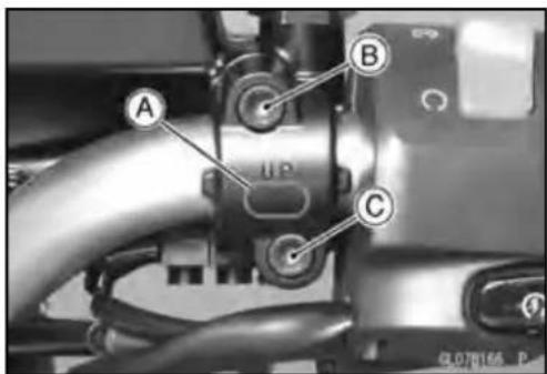
12-16BRAKES
MasterCylinder
RearMasterCylinderRemoval
- Unscrewthebrakehosebanjobolt[A]onthemastercylinder(seeBrakeHoseRemoval/Installation).
- Unscrewthemastercylindermountingbolts[A].
- Removethecotterpin[B].
NOTE
○ Pulloffthejointpinwhilepressingdownthebrake pedal.
- Pulloffthereservoirhoselowerend[C], anddrainthe brakefluidintoacontainer.
- Removethemastercylinder.
RearMasterCylinderInstallation
- Replacethecotterpin[A]withanewone.
- Replacethewashersoneachsideofhosefittingwithnew ones.
- Tightenthefollowingbolts.
Torque-RearMasterCylinderMountingBolts:25N·m(2.5 kgf·m,18ft·lb)
Brake Hose Banjo Bolt: 25N·m (2.5kgf·m
- Bleedthebrakeline(seeBrakeLineBleeding).
- Checkthebrakeforgoodbrakingpower,nobrakedrag, andnofluidleakage.
FrontMasterCylinderDisassembly
- RefertotheMasterCylinderRubberPartsReplacement inthePeriodicMaintenancechapter.
RearMasterCylinderDisassembly
- RefertotheMasterCylinderRubberPartsReplacement inthePeriodicMaintenancechapter.
MasterCylinderAssembly
- RefertotheMasterCylinderRubberPartsReplacement inthePeriodicMaintenancechapter.
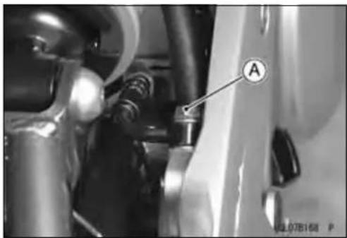
natural_image
Close-up of mechanical components with labeled component A (no readable text or symbols beyond label)

MasterCylinder
MasterCylinderInspection
- Removethemastercylinders(seeFront/RearMaster CylinderRemoval).
- Disassemblethefrontandrearmastercylinders.
- Check that there are no scratches, rust or pitting on the inner wall [A] of each master cylinder and on the outside of each piston [B].
★Ifamastercylinderorpistonshowsanydamage,replace them. - Inspecttheprimarycup[C]andsecondarycup[D].
★Ifacupisworn,damagedsoftened(rotted),orswollen, thepistonassemblyshouldbereplacedtorenewthe cups.
★ Iffluidleakage is noted at the brake lever, the piston assembly should be replaced to renew the cups.
FrontMasterCylinder[J]
- Checkthedustcovers[E]fordamage.
★ Iftheyaredamaged, replacethem. - Checkthepistonreturnsprings[F]foranydamage.
★ Ifthespringsaredamaged, replacethem. - Checkthatreliefport[G]andsupplyport[H]arenot plugged.
★ Ifthereliefportbecomesplugged, thebrakepadswill dragonthedisc. Blowtheportscleanwithcompressed air.
RearMasterCylinder[K]


BrakeDisc
BrakeDiscRemoval
- Removethewheel(seeFront/RearWheelRemovalinthe Wheels/Tireschapter).
- Unscrewthemountingbolts, and takeoffthedisc.
- Removethegaskets.
BrakeDiscInstallation
- Replacethegasketswithnewones.
- Installthebrakedisconthewheelsothatthemarkedside [A]facesout.
- Applyanon-permanentlockingagenttothethreadsof thefrontandrearbrakediscmountingbolts[B].
- Tighten:
Torque-BrakeDiscMountingBolts:27N·m(2.8kgf·m,20ft·lb)
BrakeDiscWear
- Measurethethicknessofeachdisc[A]atthepointwhere ithaswornthemost.
★Ifthedischaswornpasttheservicelimit,replaceit. MeasuringArea[B]
BrakeDiscsThickness
Standard:
Front 4.3 \~ 4.7 mm (0.17 \~ 0.19 in.)
Rear 4.8 \~ 5.2 mm (0.19 \~ 0.20 in.)
ServiceLimit:
Front 4.0mm(0.16in.)
Rear 4.5mm(0.18in.)
BrakeDiscWarp
- Raisethewheeloffthegroundwithjack(seeFront/Rear WheelRemovalintheWheels/Tireschapter).
SpecialTools-Jack:57001-1238
JackAttachment:57001-1608
○Forfrontdiscinspection, turn the handlebarfully to one side.
- Setupadialgaugeagainstthedisc[A]asshownand measurediscrunout,whileturning[B]thewheelbyhand.
★ Ifrunoutexceedstheservicelimit,replacethedisc.
DiscRunout
Standard:0.15mm(0.006in.)orless
ServiceLimit:0.3mm(0.01in.)


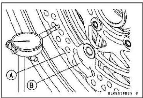
BrakeFluid
BrakeFluidLevelInspection
- RefertotheBrakeFluidLevelInspectioninthePeriodic Maintenancechapter.
BrakeFluidChange
- RefertotheBrakeFluidChangeinthePeriodicMaintenancechapter.
BrakeLineBleeding
Thebrakefluidhasaverylowcompressioncoefficientso thatalmostallthemovementofthebrakeleverorpedal istransmitteddirectlytothecaliperforbrakingaction.Air, however,iseasilycompressed.Whenairentersthebrake lines,brakeleverorpedalmovementwillbepartiallyused incompressingtheair.Thiswillmaketheleverorpedalfeel spongy,andtherewillbealossinbrakingpower.
WARNING
Besuretobleedtheairfromthebrakelinewhen-everbrakeleverorpedalactionfeelssoftor spongyafterthebrakefluidischanged,orwheneverabrakelinefittinghasbeenloosenedforany reason.
NOTE
○ Theproceduretobleedthefrontbrakelineisasfollows. Bleedingtherearbrakelineisthesameasforthefront brake.
- Removethereservoircap[A]anddiaphragm.
- Fillthereservoirwithfreshbrakefluidtotheupperlevel lineinthereservoir.
-
Slowlypumpthebrakeleversealtimesuntilnoair bubblescanbeseenrisingupthroughthefluidfromthe holesatthebottomofthereservoir.
○Bleedtheaircompletelyfromthemastercylinderbythis operation. -
Removetherubbercapfromthebleedvalve[A]onthe caliper.
- Attachaclearplastichose[B]tothebleedvalve, and run theotherendofthehoseintoacontainer.
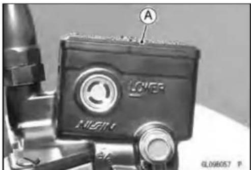
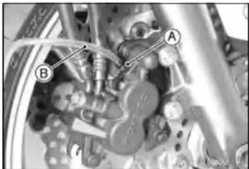
natural_image
Close-up mechanical assembly diagram showing components labeled A and B (no readable text or symbols)BrakeFluid
-
Bleedthebrakelineandthecaliper.
○Repeatthisoperationuntilnomoreaircanbeseencomingoutintotheplastichose. -
Pumpthebrakeleveruntilbecomeshard, and apply thebrakeandholdit[A].
- Quickly open and close [B] the bleed valv while holding the brake applied.
- Releasethebrake[C].
NOTE
○ Thefluidlevelmustbecheckedoftenduringthebleedingoperationandreplenishedwithfreshbrakefluidas necessary. If thefluidinthereservoirrunscompletely outanytimeduringbleeding, thebleedingoperation mustbedoneoveragainfromthebeginningsinceair willhaveenteredtheline.
○ Tapthebrakehoselightlyfromthecalipertothereservoirformorecompletebleeding.
○ FrontBrake: Firstbleedingtherightcaliperthenrepeat theabovestepsfortheleftcaliper.
- Removetheclearplastichose.
- Installthediaphragmandreservoircap.
- Tighten:
Torque-FrontBrakeReservoirCapScrews:1.0N·m(0.10 kgf·m,9in·lb)
- Follow the procedure below to install therear brake fluid reservoir cap correctly.
○First,tightentherearbrakefluidreservoircap[B]clockwise[C]byhanduntilslightresistanceisfeltindicating thatthecapisseatedonthereservoirbody,thentighten thecapanadditional1/6turn[D]whileholdingthebrake fluidreservoirbody[A].
- Tightenthebleedvalve, and installtherubbercap.
Torque-BleedValve:7.8N·m(0.80kgf·m,69in·lb)
- Checkthefluidlevel(seeBrakeFluidLevelInspectionin thePeriodicMaintenancechapter).
- Afterbleedingisdone, checkthebrakeforgoodbraking power, nobrakedrag, andnofluidleakage.


WARNING
When working with the disc brake, observ the precautions listed below.
- Neverreuseoldbrakefluid.
- Donotusefluidfromacontainerthathasbeenleft unsealedorthathasbeenopenforalongtime.
-
Donotmixtwotypesandbrandsoffluidforusein thebrake. Thislowersthebrakefluidboilingpoint andcouldcausethebraketobeineffective. It may also cause therubberbrakepartstodeteriorate.
-
Don'tleavethereservoircapofforanylengthof timetoavoidmoisturecontaminationofthefluid.
-
Don't changethe fluid in therain or when a strong wind is blowing.
-
Except forthediscpadsanddisc, use only disc brake fluid, isopropylalcohol, orethylalcohol for cleaning of the brake parts. Donot use any other fluid for cleaning these parts. Gasoline, engine oil, or any other petroleum distillate will cause deterioration of the rubber parts. Oil spilled on any part will be difficult to wash off completely and while eventually deteriorate the rubber used in the disc brake.
-
When handling the discpadsordisc, be careful that nodiscbrakefluidoranyoilgetsonthem. Cleanoff any fluidorolthatinadvertently gets on the pads or disc with a high-flash pointsolvent. Donotuse one which will leave an oily residue. Replace the pads with new ones if they cannot be cleaned satisfactorily.
-
Brakefluidquicklyruinspaintedsurfaces; any spilledfluidshouldbecompletelywipedupimmediately.
-
If any of the brakeline fittings or the bleed valve is opened at any time, the AIR MUST BE BLED FROM THE BRAKE LINE.
BrakeHose
BrakeHoseRemoval/Installation
- RefertotheBrakeHoseandPipeReplacementinthe PeriodicMaintenancechapter.
BrakeHoseInspection
- RefertotheBrakeHoseDamageandInstallationConditionInspectioninthePeriodicMaintenancechapter.
Suspension
TableofContents
Exploded View.... 13-2
Specifications 13-6
Special Tools 13-7
Front Fork 13-9
Front Fork Removal 13-9
Front Fork Installation 13-9
Front Fork Oil Change 13-9
Front Fork Disassembly 13-11
Front Fork Assembly 13-12
Inner Tube Inspection 13-13
Dust Seal Inspection 13-13
Fork Spring Inspection 13-14
Rear Shock Absorber 13-15
Spring Preload Adjustment 13-15
Rear Shock Absorber Removal 13-15
Rear Shock Absorber Installation 13-16
Rear Shock Absorber Inspection 13-16
Swingarm.... 13-17
Swingarm Removal.... 13-17
Swingarm Installation.... 13-17
Swingarm Bearing Removal 13-18
Swingarm Bearing Installation 13-18
SwingarmBearing,SleeveInspection....13-19
Swingarm Bearing Lubrication 13-20
Chain Guide Inspection.... 13-20
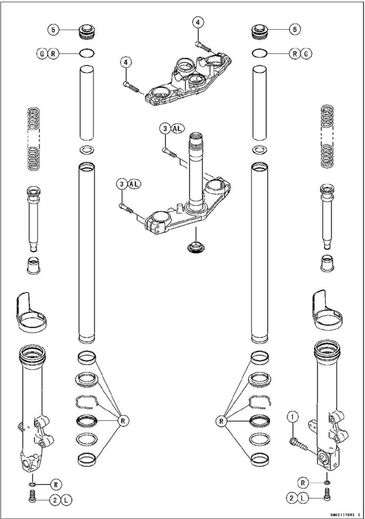
ExplodedView
| No.Fastener | Torque | Remarks | |||
| N·mkgf·mft·lb | |||||
| 1 | FrontAxleClampBolt | 343.525 | |||
| 2 | FrontForkBottomAllenBolts303.122L | ||||
| 3 | FrontForkClampBolts(Lower)202.015AL | ||||
| 4 | FrontForkClampBolts(Upper) | 202.015 | |||
| 5 | FrontForkTopPlugs252.518 | ||||
AL: Tighten the two clamp bolts alternately two times to ensure even tightening torque.
G: Apply grease.
L: Apply a non-permanentlocking agent.
R: ReplacementParts

ExplodedView
| No.Fastener | Torque | Remarks | |||
| N·mkgf·mft·lb | |||||
| 1 | RearShockAbsorberBolt | 596.044 | |||
| 2RearShockAbsorberNut596.044 | |||||
| 3SwingarmPivotShaftNut10811.080 | |||||
G:Applygrease.
R:ReplacementParts
Specifications
| ItemStandard | |
| FrontFork(PerOneUnit) | |
| ForkInnerTubeOutsideDiameter41mm | (1.6in.) |
| AirPressure | Atmosphericpressure(Non-adjustable) |
| ForkSpringSettingNon-adjustable | |
| DamperSettingNon-adjustable | |
| ForkOil: | |
| ViscosityKAYABAKHL34-G10orequivalent | |
| Amountapprox.390mL(13.2USoz.)(whenchangingoil) | |
| ForkOilLevel115±2mm(4.5±0.08in.)(belowfrominnertubetopwithfullycompressed,withoutforspring) | |
| Fork Spring Free Length | 277.8 mm (10.94 in.) (Service limit 272 mm (10.7 in.)) |
| RearShockAbsorber | |
| Spring Preload | 3rd position (Adjustable Range: 1st ~ 7th position) |
| GasPressure | 980kPa( 10kgf/cm^2 ,142psi,Non-adjustable) |
SpecialTools
InsideCirclipPliers: 57001-143

natural_image
Line drawing of a pair of pliers (no text or symbols)ForkCylinderHolderHandle: 57001-183

natural_image
Simple line drawing of a long rod or tool with a flanged end and a small circular end (no text or symbols)ForkCylinderHolderAdapter: 57001-1057

natural_image
Technical line drawing of a conical mechanical component (no text or symbols)OilSeal&BearingRemover: 57001-1058

natural_image
Technical line drawing of a mechanical component assembly (no text or symbols)BearingDriverSet: 57001-1129
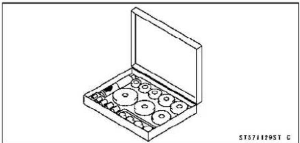
natural_image
Isometric line drawing of a box containing various circular components, no text or symbols presentJack: 57001-1238

natural_image
Technical line drawing of a mechanical support structure (no text or symbols)ForkOilSealDriver,41φ 57001-1288
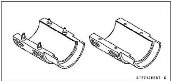
natural_image
Technical line drawing of two mechanical bracket components (no text or symbols)ForkOilLevelGauge: 57001-1290

natural_image
Technical line drawing of mechanical components including a cylindrical spring and a coiled spring (no text or symbols)JackAttachment: 57001-1608

natural_image
Technical line drawing of two mechanical fasteners with cylindrical base (no text or symbols)StemBearingDriver,28¢ 57001-1610

natural_image
Technical line drawing of a mechanical component with two views: top and side (no text or symbols)SpecialTools
Spacer,28: 57001-1663


ST571663ST C
FrontFork
FrontForkRemoval
- Remove:
FrontWheel(seeFrontWheelRemovalinthe Wheels/Tireschapter)
FrontFender(seeFrontFenderRemovalintheFrame chapter)
★Loosentheupperforkclampbolt[A]andforktopplug[B]beforehandiftheforklegistobedisassembled.
NOTE
○Loosenthetopplugafterlooseningtheupperfork clampbolt.
- Loosentheupperforkclampboltandlowerforkclamp bolts[C].
- Withatwistingmotion,worktheforklegdownandout.
FrontForkInstallation
- Installtheforkwiththeupperendoftheinnertubeflush [A]againstthetopsurfaceofthestemhead[B].
- Tighten:
Torque-FrontForkClampBolts(Lower):20N·m(2.0 kgf·m,15ft·lb)
FrontForkTopPlug:25N·m(2.5kgf·m,18ft·lb)
NOTE
○ Tightenthetopplugbeforetighteningtheupperfork clampbolt.
○ Tightenthetwoclampboltsalternatelytwotimestoensureeventighteningtorque.
- Tighten:
Torque-FrontForkClampBolt(Upper):20N·m(2.0kgf·m, 15ft·lb) - Installtheremovedparts(seeappropriatechapters).
FrontForkOilChange
- Removethefrontfork(seeFrontForkRemoval).
- Remove:
Top Plug [A] with O-ring Collar[B]
ForkSpringSeat[C]
ForkSpring[D]


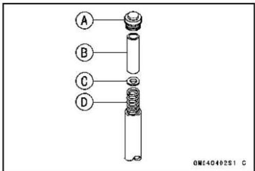
FrontFork
- Compress[A]thefork[B]upsidedowntodrawouttheoil intothesuitablecontainer[C].
- Pourinthespecifiedamountofoil.
ForkOil
Viscosity:
KAYABAKHL34-G10or equivalent
Amount(PerSide):
Whenchangingoil: approx.390mL(13.2USoz.)
Afterdisassembly
andcompletelydry:458±4mL(15.5±0.14USoz.)
NOTE
○ Movetheoutertubeupanddownafewtimestoremove theairthatistrappedintheforkoilinordertostabilize theoillevel.
- Holdtheoutertubeverticallyinaviseandcompressthe forkcompletely.
- Waituntiltheoillevelstabilizes.
- Usetheforkoillevelgauge[A]tomeasurethedistance betweenthetopoftheinnertubetotheoillevel.
SpecialTool-ForkOilLevelGauge:57001-1290
○Settheoillevelgaugestopper[B]sothatthedistance[C] fromthebottomofthestoppertothelowerendofthepipe isthestandardoilleveldistance.
○Acorrectmeasurementcannotbeobtainedunlessthe levelgaugepipeisplacedinthecenteroftheinnertube.
OilLevel(fullycompressed, withoutspring)
Standard:115±2mm(4.5±0.08in.)
-
Placethestopperofthelevelgaugeatthetop[D]ofthe innertube[E]andpullthehandleslowlytodrawoutthe excessoilfromforkintothegauge,thusattainingthestandardlevel.
Olfnotoilisdrawnout, there is not enough oil in the fork. Pour insomemore oil and measure again. -
Repeatthesameprocedureforadjustingtheotherfork.
- Installtheforkspring[A],forkspringseat[B]andcollar [C].
- InspectthetopplugO-ringandreplaceitwithanewone.
- Installthefrontfork(seeFrontForkInstallation).

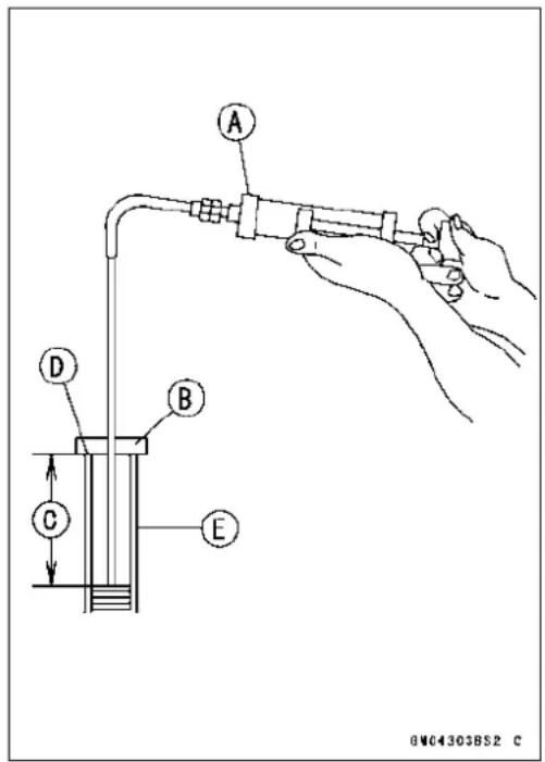

FrontFork
FrontForkDisassembly
- Removethefrontfork(seeFrontForkRemoval).
- Removethetopplug[A]withO-ring,takeoutthecollar [B],forkspringseat[C],andforkspring[D].
- Draintheforkoil(seeFrontForkOilChange).
- RemovetheAllenbolt[A]fromthebottomofthefork. SpecialTools-ForkCylinderHolderHandle[B]:57001-183 ForkCylinderHolderAdapter[C]:57001 -1057
NOTE
○Holdtheoutertubeinavise[D],stopthecylinderunit[E]fromturningbyusingthespecialtools,andunscrew theAllenbolt.
- Removethecylinderunit[A], washer, and the spring[B] from the innertube.
- Removethefollowingfromthetopoftheoutertube. DustSeal[A] RetainingRing[B]
- Separatetheinnertube[A]fromtheoutertube[B].
NOTE
○Fromthecompressedstate, firmlypulldowntheouter tubeafewtimestowardsthedirectionofelongation.


natural_image
Mechanical component with labeled parts A and B, showing internal structure without any text or symbols beyond labels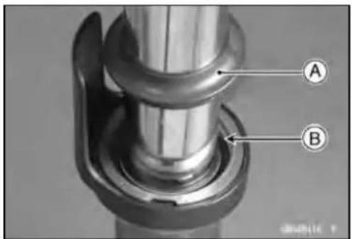

13-12 SUSPENSION
FrontFork
- Removethefollowingfromtheinnertube.
InnerGuideBushing[A]
OuterGuideBushing[B]
Washer[C]
OilSeal[D]
- Removethecylinderbase[A]fromthebottomoftheouter tube.
FrontForkAssembly
- CheckthetopplugO-ringandreplaceitwithanewone.
- Replacethefollowingpartswithnewones.
RetainingRing[A]
DustSeal[B]
OilSeal[C]
InnerGuideBushing[D]
OuterGuideBushing[E]
ForkBottomAllenBoltGasket[F]
• Installtheguidebushingontheendoftheinnertube.
- Insertthecylinderunitandthespringintotheinnertube, andinstallthecylinderbase[A]ontothecylinderend[B] thatprotrudesfromthebottom.
○Installthecylinderbasestartingwithitssteppedend.
- Inserttheinnertube, cylinderunit, washer, spring, and cylinderbaseasasetintotheoutertube.
• Installtheguidebushingintotheoutertube.
- Afterinstallingthewasher, installtheoilseal[A]byusing theforkoilsealdriver[B].
SpecialTool-ForkOilSealDriver,41:57001-1288
• Installtheretainingringintotheoutertube.
• Installthedustsealbyhand.


natural_image
Close-up of a mechanical component with a white connector labeled 'A' and a metallic handle (no text or symbols beyond label)
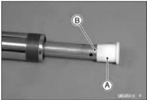
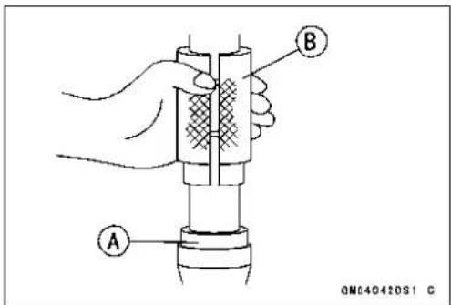
FrontFork
- Applynon-permanentlockingagenttothethreadsofthe bottomAllenbolt[A].
- Holdthefrontforkhorizontallyinavise[B].
- Holdthecylinderunit[C]withthespecialtoolsandtighten thebottomAllenbolttosecurethecylinderinplace.
Torque-FrontForkBottomAllenBolt:30N·m(3.1kgf·m, 22ft·lb)
SpecialTools-ForkCylinderHolderHandle[D]:57001-183
ForkCylinderHolderAdapter[E]:57001
-1057
- Pourinthespecifiedtypeofoil(seeFrontForkOil Change).
InnerTubeInspection
- Visually inspect the innertube[A], and repair any damage.
- Nicksorrustdamagecansometimesberepairedbyusing awet-stonetoremovesharpedgesorraisedareaswhich causesealdamage.
★ Ifthedamageisnotrepairable,replaceiinnertube. Sincedamagetotheinnertubedamagestheoilseal, replacetheoilsealwhenevertheinnertubeisrepaired orreplaced.
CAUTION
Iftheinnertubeisbadlybentorcreased,replace it.Excessivebending,followedbysubsequent straightening,canweakentheinnertube.
- Temporarily assemble the inner and outer tubes, and pumpthemback and forthmanually to check for smooth operation.
- If you feel binding or catching, the inner and outer tubes must bereplaced.
WARNING
Astraightenedinnerorouterforktubemayfallin use, possibly causing an accident. Replace abadly bentordamaged inneroroutertube and inspect the othertubecarefully before reusing it.
DustSealInspection
- Inspectthedustseal[A]foranysignsofdeteriorationor damage.
★Replaceitifnecessary.
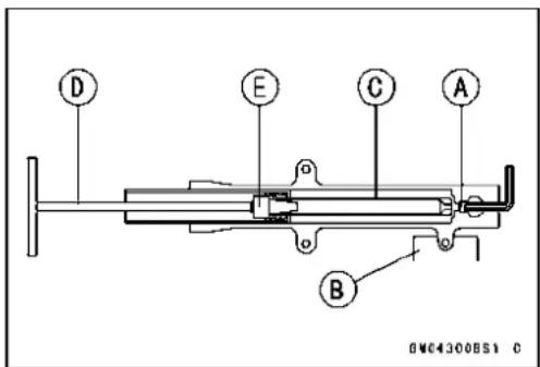

natural_image
Technical line drawing of a cylindrical mechanical component with a labeled connection point A (no text or symbols beyond label)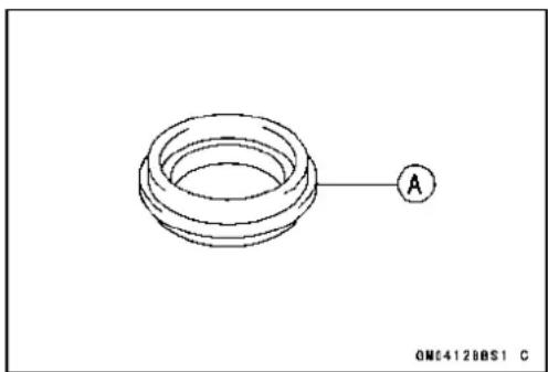
natural_image
Technical line drawing of a coiled spring with a labeled point A (no text or symbols beyond label)FrontFork
ForkSpringInspection
- Measurethefreelength[A]oftheforkspring[B].
★Ifthemeasuredlengthisshorterthantheservicelimit,the springmustbereplaced.Ifthefreelengthofthereplacementspringandthatoftheremainingspringvarygreatly, theremainingspringshouldalsobereplacedinorderto keeptheforklegsbalancedtoensurestability.
ForkSpringFreeLength
Standard:277.8mm(10.94in.)
ServiceLimit:272mm(10.7in.)
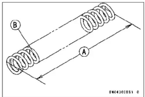
RearShockAbsorber
SpringPreloadAdjustment
- Usingthehookwrench[A],turntheadadjustingnut[B]to adjustthespringpreload.
○Thestandardadjustersettingforaverage-buildriderof68 kg(150lb)withnopassengerandnoaccessoriesis3rd position.
SpringPreloadSetting
StandardPosition: 3rdposition
AdjustableRange:1stto7thposition
- If the compression of the spring is not suited to the operating conditions, adjust to an appropriate position by referring to the table below.
SpringPreloadAdjustment
| Adjuster Position | Damping Force | Shock Absorber Hardness | Load | Road Conditions | Driving Speed |
| 1stWeak↑ ↑↓ ↓7th | ↑ ↑ ↑↓ ↓ ↓Strong | Soft↑↓Hard | Light | Good | Low |
| Heavy | Bad | Highway |
RearShockAbsorberRemoval
- Remove:
FrameCovers(seeFrameCoverRemovalintheFrame chapter)
MufflerBody(see Muffler Body Removal in the Engine Top End chapter)
- Raisetherearwheeloffthegroundwithjack.
Special Tools - Jack:57001-1238
JackAttachment:57001-1608
- Squeezethebrakeleverslowlyandholditwithaband [A].
WARNING
Besuretoholdthefrontbrakewhenremovingthe shockabsorber,orthemotorcyclemaytallover. It could cause an accident and injury.
- Remove:
RightStayCover[A]

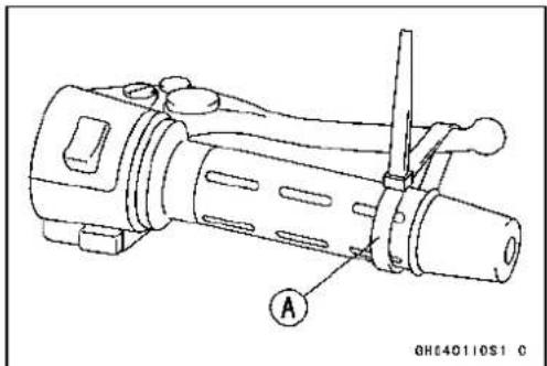

natural_image
Close-up of a mechanical component with labeled point A and reference number 00258196 P (no readable text or symbols beyond labels)13-16 SUSPENSION
RearShockAbsorber
- Remove:
UpperShockAbsorberBolt[A] LowerShockAbsorberNutandWasher LowerShockAbsorberBolt[B]
- Removetheshockabsorber[C]frombackward.
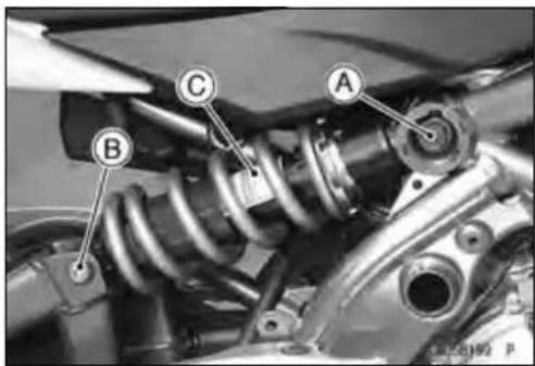
RearShockAbsorberInstallation
- Installationisthereverseofremoval. - Applygreasetothelipofoilsealsandbearingofrear shockabsorber.
○Besuretoinstalltheoilsealstotheshockabsorber.
- Tighten:
Torque-RearShockAbsorberBolt:59N·m(6.0kgf·m,44 ft·lb) RearShockAbsorberNut:59N·m(6.0kgf·m,44 ft·lb)
• Installtheremovedparts(seeappropriatechapters).
RearShockAbsorberInspection
- Removetherearshockabsorber(seeRearShockAbsorberRemoval).
- Visuallyinspectthefollowingitems. SmoothStroke OilLeakage CrackorDent
★Ifthereisanydamagetotherearshockabsorber,replace it.
- Visuallyinspecttherubberbushing.
★Ifitshowanysignsofdamage,replaceit.
Swingarm
SwingarmRemoval
- Remove: ChainCoverBolts[A]andCover[B]
- Remove: RightSideCover(seeSideCoverRemovalintheFrame chapter) FrameCovers(seeFrameCoverRemovalintheFrame chapter)
- Removethebrakehosebanjoboltfromtherearcaliper, freethebrakehose[A]fromtheclamps[B], and remove thefootpegstaywiththerearmastercylinder(seeRear CaliperRemovalintheBrakeschapter).
- Remove: MufflerBody(seeMufflerBodyRemovalintheEngine TopEndchapter) RearWheel(seeRearWheelRemovalinthe Wheels/Tireschapter)
- Raisetherearwheeloffthegroundwithjack.
SpecialTools-Jack:57001-1238 JackAttachment:57001-1608
- Removethelowershockabsorbernutandbolt[A].
- Removethedrivechain(seeDriveChainRemovalinthe FinalDrivechapter).
- Unscrewtheswingarmpivotshaftnut[A].
- Pulloffthepivotshaft[B], andremovetheswingarm.


natural_image
Close-up of mechanical components with labeled section A (no readable text or symbols)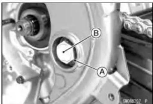
SwingarmInstallation
- Installationisthereverseofremoval.
○Applygreasetothelipoftheoilseals.
○Besuretoinstalltheoilsealandcollartotheswingarm. - Tightenthepivotshaftnut.
Torque-SwingarmPivotShaftNut:108N·m(11.0kgf·m, 80ft·lb)
- Installtheremovedparts(seeappropriatechapters).
Swingarm
SwingarmBearingRemoval
- Remove:
Swingarm(seeSwingarmRemoval)
Collar[A]
OilSeals[B]
Sleeve[C]
Circlip[D]
SpecialTool-InsideCirclipPliers:57001-143
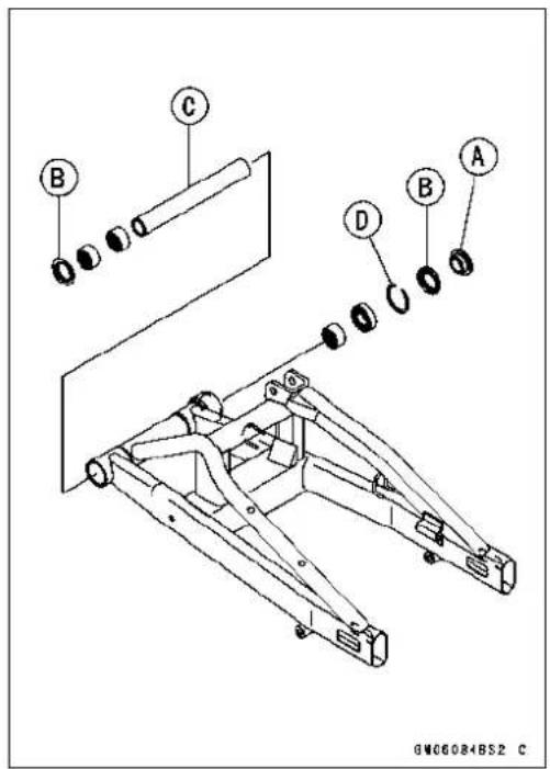
- Removetheballbearingandneedlebearings.
SpecialTool-OilSeal&BearingRemover[A]:57001-1058
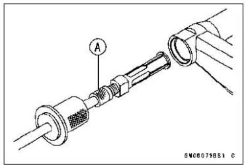
SwingarmBearingInstallation
- Replacetheballandneedlebearings[A]withnewones.
- Installtheballandneedlebearingssothatthemanufac-turer'smarksfaceout.
SpecialTools-BearingDriverSet:57001-1129
StemBearingDriver, 28[B] :57001-1610
Spacer, 28:57001 - 1663
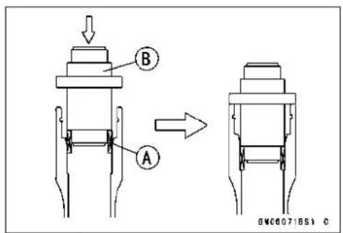
Swingarm
- Installtheneedlebearings[A],ballbearing[B]andoil seals[C]positionasshown.
Circlip[D]
25mm(0.98in.)[E]
17mm(0.67in.)[F]
1mm(0.04in.)[G]
0.5mm(0.02in.)[H]
1mm(0.04in.)[l]
23.5mm(0.93in.)[J]
6mm(0.24in.)[K]

SwingarmBearing, SleeveInspection
CAUTION
Donotremovethebearingsforinspection. Removalmaydamagethem.
- Inspecttheneedlebearings[A]andballbearinginstalled intheswingarm.
○Therollersandballinabearingnormallywearverylittle, andwearisdifficulttomeasure.Insteadofmeasuring, visuallyinspectthebearingforabrasion,discoloration,or otherdamage.
★ Iftheneedlebearingandsleeve[B]showanysingsof abnormalwear,discoloration,ordamage,replacethem asaset.

13-20 SUSPENSION
Swingarm
- Turnthebearingintheswingarmbackandforth[A]while checkingforplays,roughness,orbinding.
★Ifthebearingplay,roughness,orbindingisfound,replace thebearing. - Examinethebearingseal[B]fortearsorleakage.
★Ifthesealistornorisleaking,replacehebearing.

SwingarmBearingLubrication
NOTE
○ Sincethebearingsarepackedwithgreaseandsealed, lubricationisnotrequired.
ChainGuideInspection
- RefertotheChainGuideWearInspectioninthePeriodic Maintenancechapter.
Steering
TableofContents
Exploded View.... 14-2
Special Tools 14-4
Steering 14-5
Steering Inspection 14-5
Steering Adjustment.... 14-5
Steering Stem.... 14-6
Stem, Stem Bearing Removal.... 14-6
Stem, Stem Bearing Installation.... 14-7
Stem Bearing Lubrication.... 14-8
Steering Stem Warp 14-9
StemCapDeterioration,Damage....14-9
Handlebar 14-10
Handlebar Removal 14-10
Handlebar Installation 14-10

ExplodedView
| No.F | Fastener | Torque | Remarks | ||
| N·mkgf·mft·lb | |||||
| 1 | FrontForkClampBolts(Lower) | 202.015 | AL | ||
| 2 | FrontForkClampBolts(Upper)202.015 | ||||
| 3 | HandlebarHolderBolts252.518S | ||||
| 4 | Left Switch Housing Screws | 3.5 | 0.36 | 31 in·lb | |
| 5 | Right Switch Housing Screws | 3.5 | 0.36 | 31 in·lb | |
| 6 | Steering Stem Head Bolt | 108 | 11.0 | 80 | |
| 7 | SteeringStem Nut | 202.015 | |||
AD: Apply adhesive.
AL: Tighten the two clamp bolts alternately two times to ensure even tighten torque.
G: Apply grease.
L: Apply a non-permanent locking agent.
R: Replacement Parts
S: Follow the specified tightening sequence.
SpecialTools
SteeringStemNutWrench: 57001-1100

natural_image
Line drawing of a mechanical wrench tool (no text or symbols present)BearingDriverSet: 57001-1129
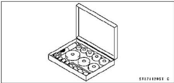
natural_image
Isometric line drawing of a box containing multiple circular components, no text or symbols presentSteeringStemBearingDriver,42.5: 57001-1344
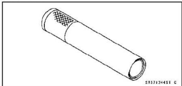
natural_image
Technical line drawing of a cylindrical mechanical component with a textured inner layer (no text or symbols)SteeringStemBearingDriverAdapter,41.5:57001-1345

natural_image
Simple line drawing of a cylindrical object with layered top surface (no text or symbols)Steering
SteeringInspection
- RefertotheSteeringPlayInspectioninthePeriodicMaintenancechapter.
SteeringAdjustment
- RefertotheSteeringPlayAdjustmentinthePeriodic Maintenancechapter.
SteeringStem
Stem, StemBearingRemoval
- Remove:
FrontWheel(seeFrontWheelRemovalinthe
Wheels/Tireschapter)
HeadlightAssy(seeHeadlightRemoval/Installationin theElectricalSystemchapter)
Handlebar(seeHandlebarRemoval)
SteeringStemHeadBoltPlug[A]
SteeringStemHeadBolt[B]andWasher
FrontForkClampBolts(Upper)C
SteeringStemHead[D]
- Remove:
UnderBracketA
FrontForks(seeFrontForkRemovalintheSuspension chapter)
- Straightentheclaws[A]oftheclawwasher.
- Removethesteeringstemlocknut[B]andclawwasher [C].
- Pushingupthestembase, andremovethesteeringstem nut[A]withstemcap[B].
SpecialTool-SteeringStemNutWrench[C]:57001-1100
- Removethesteeringstem[D] underside.
- Removetheupperstembearinginnerraceandbearing.
- Toremovethebearingouterraces[A]pressedintothe headpipe[B],insertabar[C]intotherecessesofhead pipe,andapplyingittobothrecessalternatelyhammerit todrivetheraceout.
NOTE
○ Ifeithersteeringstembearingisdamaged,itisrecommendedthatboththeupperandlowerbearings(includingouterraces)shouldbereplacedwithnewones.


natural_image
Close-up of a mechanical assembly with visible components and a labeled section (A), no readable text or symbols present.
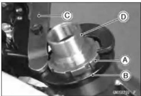

SteeringStem
- Removethelowerbearinginnerrace[A]whichispressed ontothesteeringstemwithasuitablecommerciallyavailablechisel[B].
Stem, StemBearingInstallation
- Replacethebearingouterraceswithnewones.
- Applygreasetotheouterraces, and drivetheminto the headpipeatthesametime.
SpecialTool-BearingDriverSet[A]:57001-1129
- Replacethebearinginnerracesandoilsealwithnew ones.
- Applygreasetotheoilseal.
- Drivethelowerballbearinginnerraceappliedthegrease ontothestem.
SpecialTools-SteeringStemBearingDriver,42.5[A]: 57001-1344
SteeringStemBearingDriverAdapter, 41.5[B]:57001 - 1345
- Applygreasetothelowerballbearing[A], and install it onto the stem.
-
Applygreasetotheupperballbearing[B]andinnerrace [C].
-
Installthestem[A]throughtheheadpipeandinstallthe ballbearing[B]andinnerrace[C]onit.
- Installthestemcap[D]andsteeringstemnut[E].


natural_image
Close-up of a mechanical component with labeled section A (no readable text or symbols)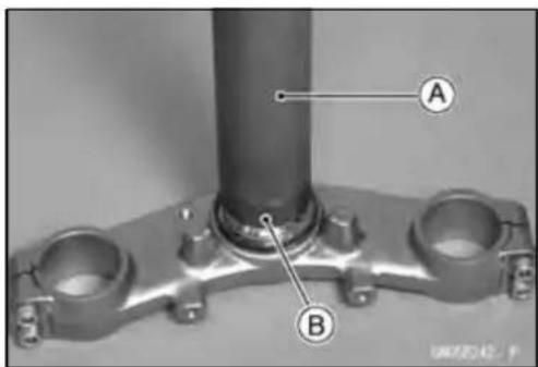

natural_image
Three ball bearing rings labeled A, B, and C, shown in grayscale without any text or symbols.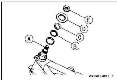
SteeringStem
- Settletheinnerracesinplaceasfollows.
○Tightenthesteeringstemnutwith39N·m(4.0kgf·m,29ft·lb)oftorquefirst,andloosenitafractionofaturnuntilitturnslightly.Afterwardtightenitagainwithspecifiedtorqueusingastemnutwrench[A]inthedirectionshown.
○Checkthatthereisnoplayandthesteeringstemturns smoothlywithouttrattles.Ifnot,thesteeringstembearings maybedamaged.
SpecialTool-SteeringStemNutWrench:57001-1100
Torque-SteeringStemNut:20N·m(2.0kgf·m,15ft·lb)
- Installtheclawwasher[A]sothatitsbentside[B]faces upward, and engage the bent claw with the grooves of stemlocknut[C].
- Handtightenthestemlocknutuntilittouchestheclaw washer.
- Tightenthestemlocknutclockwiseuntiltheclawsare alignedwiththegrooves(rangingfrom2ndto4th)ofstem nut[D],andbendthe2clawsdownward[E].
- Installthestemhead.
- Installthewasher, and tightenthestemheadbolt with specified torque.
- Installthefrontforks(seeFrontForkInstallationinthe Suspensionchapter).
NOTE
○ Tightentheupperforkclampboltsfirst, nextthestem headbolt, lastthelowerforkclampbolts.
○ Tightenthetwoclampboltsalternatelytwotimestoensureeventighteningtorque.
Torque-FrontForkClampBolts(Upper): 20N·m(2.0 kgf·m,15ft·lb)
SteeringStemHeadBolt:108N·m(11.0kgf·m,80ft·lb)
FrontForkClampBolts(Lower): 20N·m(2.0 kgf·m,15ft·lb)
WARNING
Donotimpedethehandlebarturningbyroutingthe cables,harnessesandhosesimproperly(seeCable, Wire,andHoseRoutingsectionintheAppendixchapter).
• Installthesteeringstemheadboltplug.
- Installtheremovedparts(seeappropriatechapters).
StemBearingLubrication
- RefertotheSteeringStemBearingLubricationinthePeriodicMaintenancechapter.


SteeringStem
SteeringStemWarp
- Whenever thesteering stem is removed, or if thesteering cannot be adjusted for smooth action, check thesteering stem for straightness.
★ Ifthesteeringstem[A]isbent,replacesteeringstem.

StemCapDeterioration, Damage
★Replacethestemcapifitsoilseal[A]showsdamage.

natural_image
Close-up of a hand holding a coiled black hose with a labeled component (A), no visible text or symbols on the object itself.14-10STEERING
Handlebar
HandlebarRemoval
-
Remove:
ClutchLeverAssembly[A]
LeftSwitchHousing[B]
LeftHandlebarWeight[C] -
Remove:
FrontBrakeMasterCylinderA
RightSwitchHousing[B]
RightHandlebarWeight[C]
ThrottleGrip[D] -
Removethehandlebarholderbolts[A].
- Removethehandlebarholder[B]andthenpulloutthe handlebar.
HandlebarInstallation
- Alignthepunchmark[A]onthehandlebarandthecorner edge[B]onthestemhead.
- Tightenthefrontholderboltsfirst, andthentherearholder bolts. Therewillbeagap[A]attherearpartofthehandlebarholderaftertightening.
Torque-HandlebarHolderBolts:25N·m(2.5kgf·m,18ft·lb)
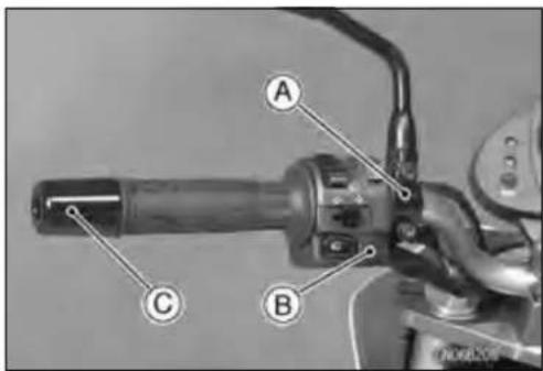


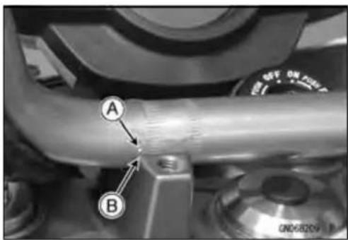
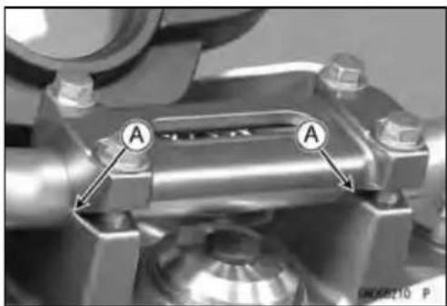
natural_image
Close-up of a mechanical component with two labeled points A, showing no visible text or symbols.Handlebar
- Installtheclutchlever(seeClutchLeverInstallationinthe Clutchchapter).
- Applyadhesivecementtotheinsideofthelefthandlebar grip.
-
Applyanon-permanentlockingagenttothelefthandlebar weightbolt.
• Installtheleftswitchhousing.
○Fittheprojection[A]intoasmallhole[B]inthehandlebar.
Torque-LeftSwitchHousingScrews:3.5N·m(0.36kgf·m, 31in·lb) -
Install:
ThrottleGrip
ThrottleCableTips[A]
RightSwitchHousing
○Fittheprojection[B]intoasmallhole[C]inthehandlebar.
Torque-RightSwitchHousingScrews:3.5N·m(0.36 kgf·m,31in·lb)
- Applyanon-permanentlockingagenttotherighthandlebarweightbolt.
- Installthefrontbrakemastercylinder(seeFrontMaster CylinderInstallationintheBrakeschapter).


Frame
TableofContents
Exploded View 15-2
Seat 15-8
Seat Removal 15-8
Seat Installation 15-8
Fairings.... 15-9
Lower Fairing Removal 15-9
Lower Fairing Installation 15-9
Center Fairing Removal 15-9
Center Fairing Installation 15-9
Upper Fairing Removal 15-10
Upper Fairing Installation 15-10
Upper Fairing Bracket Removal 15-10
Inner Fairing Removal.... 15-11
Inner Fairing Installation.... 15-11
Side Covers 15-12
Side Cover Removal 15-12
Side Cover Installation 15-12
Seat Covers.... 15-13
Seat Cover Removal 15-13
Seat Cover Installation.... 15-13
Fenders 15-14
Front Fender Removal 15-14
Front Fender Installation 15-14
Flap and Rear Fender Rear Removal 15-14
Flap and Rear Fender Rear Installation 15-14
Rear Fender Front Removal 15-15
Rear Fender Front Installation 15-15
Frame 15-16
Frame Inspection 15-16
Sidestand.... 15-17
Sidestand Removal 15-17
Sidestand Installation.... 15-17
Frame Cover.... 15-18
Frame Cover Removal 15-18
Frame Cover Installation.... 15-18
Rear View Mirrors.... 15-19
Rear View Mirrors Removal 15-19
Rear View Mirrors Installation.... 15-19

ExplodedView
| No.Fastener | Torque | Remarks | |||
| N·mkgf·mft·lb | |||||
| 1 | FootpegStayBolts | 343.525 | |||
| 2SidestandBolt444.533 | |||||
| 3SidestandSwitchBolt8.80.9078in·lbL | |||||
G:Applygrease.
L: Applyanon-permanentlockingagent.
R:ReplacementParts

ExplodedView
| No.Fastener | Torque | Remarks | |||
| N·mkgf· | mft·lb | ||||
| 1 | FrontFenderBolts3.90.4035in·lb | ||||
| 2 | Front Fender Bracket Bolts | 8.8 | 0.90 | 78 in·lb | L |
L: Applyanon-permanentlockingagent.

ExplodedView
| No.Fastener | Torque | Remarks | |||
| N·mkgf· | mft·lb | ||||
| 1 | GrabRailMountingBolts | 252.518 | |||
| 2 | Lower Fairing Mounting Bolts | 8.8 | 0.90 | 78 in·lb | |
15-8FRAME
Seat
SeatRemoval
- Inserttheignitionswitchkey[A]intotheseatlock,turning thekeyclockwise,pullingupontherearoftheseat[B], andpullingtheseatbackward.
SeatInstallation
- Sliptheseathook[A]underthebrace[B]onthefueltank bracket.
- Inserttheseatlatch[A]intothelatchhole[B].
- Pushdowntherearpartoftheseatuntilthelockclicks.


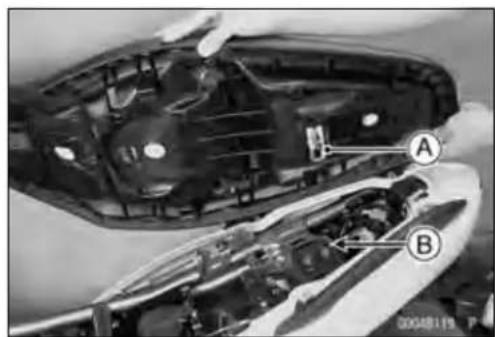
Fairings
LowerFairingRemoval
- Removethemountingbolts[A]andlowerfairing[B].

natural_image
Mechanical assembly diagram showing components labeled A and B (no readable text or symbols beyond labels)LowerFairingInstallation
- Installthelowerfairing, andtightenthemountingbolts.
Torque-LowerFairing, Mounting Bolts: 8.8N·m (0.90 kgf·m, 78in·lb)
CenterFairingRemoval
- Removethemountingbolts[A].
- Pullthecenterfairing[B]evenlyoutwardtoclearthestoppers.
- Disconnecttheturnsignalleadconnector[A].


natural_image
Close-up of mechanical components with visible wiring and a labeled section (A), no readable text or symbols present.- Removetheinnerfairing(seeInnerFairingRemoval).
- Removethebracketscrews[A]andturnsignallight[B].

CenterFairingInstallation
- Installtheturnsignallighttothecenterfairing.
- Installtheinnerfairing(seeInnerFairingInstallation).
Fairings
- Connecttheturnsignalleadconnector.
- Inserttheprojections[A]intotheholes[B].
• Installthemountingbolts.
UpperFairingRemoval
- Remove:
HeadlightAssy(seeHeadlightRemoval/Installationin theElectricalSystemchapter) MountingBolts[A] UpperFairings


natural_image
Close-up of a mechanical component with labeled parts A, showing internal structure and mounting holes (no readable text or symbols)UpperFairingInstallation
- Installationisthereverseofremoval.
UpperFairingBracketRemoval
- Remove: HeadlightAssy(seeHeadlightRemoval/Installationin theElectricalSystemchapter) MeterUnit(seeMeterUnitRemovalintheElectricalSystemchapter) Bolts[A]
- Freethefollowingpartsfromthebracket. ClutchCable IgnitionSwitchLead MainHarness BrakeHose ThrottleCables SwitchHousingLeads
- Removetheupperfairingbracket[B].
- Remove: Clamp[A] Bolts[B] UnderBracket[C]

natural_image
Mechanical assembly diagram showing interconnected components labeled A and B (no readable text or symbols beyond labels)
Fairings
InnerFairingRemoval
- Remove: CenterFairings(seeCenterFairingRemoval) MountingScrews[A] InnerFairing[B]

InnerFairingInstallation
- Tightenthemountingscrews.
- Installthecenterfairings(seeCenterFairingInstallation).
15-12FRAME
SideCovers
SideCoverRemoval
- Removetheseat(seeSeatRemoval).
- Removethebolt[A].
- Pullthesidecover[B]evenlyoutwardtoclearthestoppers.
SideCoverInstallation
- Insertthetabs[A]intotheholes[B].
- Tightenthebolt.
- Installtheseat(seeSeatInstallation).
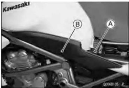

SeatCovers
SeatCoverRemoval
-
Remove:
Seat(seeSeatRemoval)
Bolts[A]
GrabRails[B]
ScrewRivets[C] -
Pushthecentralpin, and then removethe quickrivets[A].
- Pullthefrontandrearportionsoftheseatcoveroutside, andthenremovetheseatcovers.
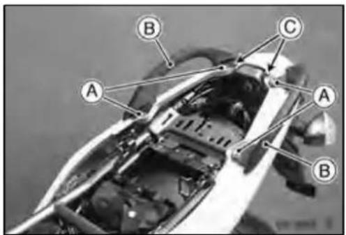

SeatCoverInstallation
- Installationisthereverseofremoval.
- Puttheprojection[A]intothegrommet[B]ontherear fenderrear.


- Puttheprojection[A]intothehole[B]oftheseatcover.
• Install: GrabRailsandBolts
Torque-GrabRailMountingBolts:25N·m(2.5kgf·m,18 ft·lb)
- Inserttheprojections[A]ofthecenterseatcoverintothe holes[B]ofthesideseatcover.
- Install: ScrewRivets Seat(seeSeatInstallation)

15-14FRAME
Fenders
FrontFenderRemoval
- Remove: BrakeHoseClamps[A] Bolts[B]withCollar(BothSide)
- Removethefrontfender[C].
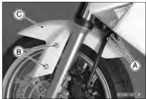
FrontFenderInstallation
- Tighten: Torque-FrontFenderBolts:3.9N·m(0.40kgf·m,35in·lb)
- Installthebrakehoseclampstothefrontfenderholes.
FlapandRearFenderRearRemoval
- Remove: Seat(seeSeatRemoval) SeatCovers(seeSeatCoverRemoval) Tail/BrakeLightA
- Remove: Nuts[A]andBolts[B] Flap(withLicensePlateLight)

natural_image
Close-up of a mechanical component with labeled point A (no readable text or symbols)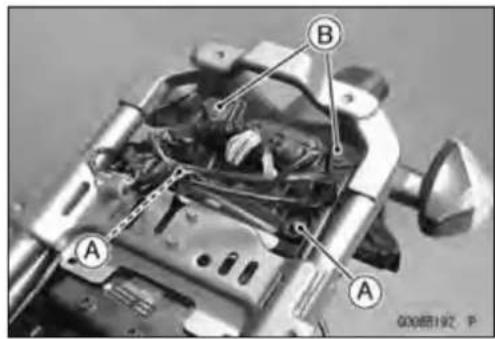
- Remove: SeatLockCableLowerEnd[A] QuickRivet[B]
- Freetheclampsfromtherearfenderrear.
- Pullouttherearfenderrearbackwardanddownward.

natural_image
Close-up mechanical assembly showing internal components with labeled parts A and B (no readable text or symbols beyond labels)FlapandRearFenderRearInstallation
- Installationisthereverseofremoval.
Fenders
RearFenderFrontRemoval
- Remove:
RearFenderRear(seeFlapandRearFenderRearRemoval) Battery(seeBatteryRemovalintheElectricalSystem chapter) RelayBox(seeRelayBoxRemovalintheElectricalSystemchapter) StarterRelay(seeStarterRelayInspectionintheElectricalSystemchapter)
- Removethefuseboxfromtherearfenderfront.
- Remove: Bolt[A] Clamp[B]
- Freetheclampfromtherearfenderfront.
- Removetherearfenderfront[A]backwardandupward.
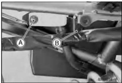

natural_image
Close-up of mechanical components with a labeled component 'A' and an arrow pointing to it (no readable text or symbols)RearFenderFrontInstallation
- Installationisthereverseofremoval.
- Installtheremovedparts(seeappropriatechapters).
Frame
FrameInspection
- Visually inspect the frame for cracks, dents, bending or warp.
○Ifthereisanydamagetotheframe,replaceit.
WARNING
Arepairedframemayfailinuse, possibly causing an accident. If the frame is bent, dented, cracked, or warped, replace it.
Sidestand
SidestandRemoval
- Raisetherearwheeloffthegroundwithstand.
- Remove:
FrameCover(seeFrameCoverRemoval) Bolts[A] FootpegStay[B]
- Remove: SidestandSwitchBolt[A]withClamp SidestandSwitch[B]
- Remove: Spring[A] SidestandNut[B] SidestandBolt[C] Sidestand[D]


natural_image
Mechanical assembly diagram showing two labeled components A and B, no readable text or symbols present.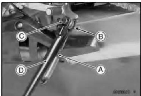
SidestandInstallation
- Applygreasetotheslidingarea[A]ofthesidestand[B].
- Tightentheboltandlockthemwiththenut.
Torque-SidestandBolt:44N·m(4.5kgf·m,33ft·lb) - Hookthespring.
• Installthesidestandswitch.
○Applyanon-permanentlockingagenttothethreadofthe switchbolt.
Torque-SidestandSwitchBolt:8.8N·m(0.90kgf·m,78in·lb)
• Installthefootpegstay.
- Tighten:
Torque-FootpegStayBolts:34N·m(3.5kgf·m,25ft·lb)
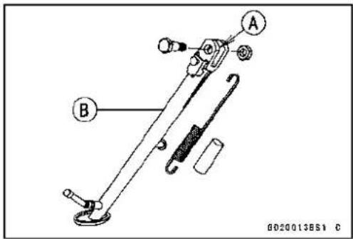
15-18FRAME
FrameCover
FrameCoverRemoval
- Removethebolt[A].
- Pulltheframecover[B]outwardtoclearthestoppers.
FrameCoverInstallation
- Inserttheprojections[A]intotheholes[B].
- Tightenthebolt.
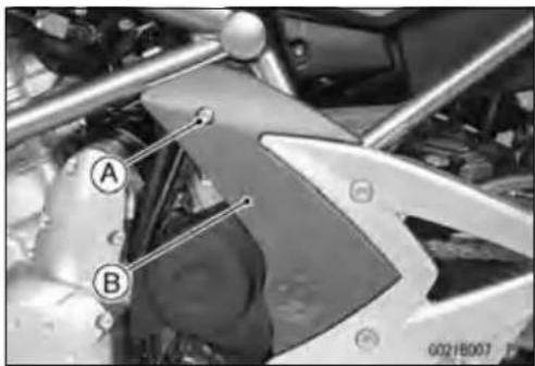
natural_image
Close-up of a motorcycle's front wheel and side-mounted sensors (no visible text or symbols)
RearViewMirrors
RearViewMirrorsRemoval
- Loosenthelowerhexagonalarea[A]fortighteningtoremovetherearviewmirrorfromtheholder.
CAUTION
Donotforcetotightenand/orloosentheupper hexagonalarea(adapter)[B]withapairofspanners.DisassemblyofthisareaisNotAvailable. Non-permanentlockingagent[C]isalreadyapplied tothethreadsofthisinnerarea.Forciblelooseningmaydamagetheadapterand/ortheturning mechanismofthestay[D].
RearViewMirrorsInstallation
- Screwthemountingareaoftherightrearviewmirrorinto theholderalltheway,andtightenthelowerhexagonal areafortighteningsecurely. LowerHexagonalAreaforTightening[A] UpperHexagonalArea(Adapter)[B] RearViewMirror(Right)[C]
- Turnthestay[A]toassurethesafeconditionsoftherear withtheoperatorsatonthemotorcycle. - Adjusttherearviewmirrorslightlywithitsmirror[B]. ○Installationandadjustmentoftheleftsidearecommon withthoseoftherightside.Followtheproceduresspecifiedattherightside.

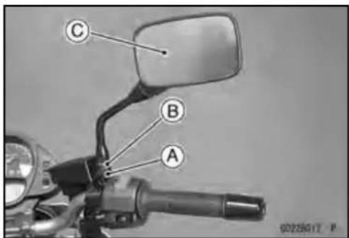

ElectricalSystem
TableofContents
Exploded View.... 16-3
Specifications 16-10
Special Tools and Sealants 16-11
Parts Location.... 16-12
Wiring Diagram.... 16-14
Precautions.... 16-16
Electrical Wiring.... 16-18
Wiring Inspection 16-18
Battery 16-19
Battery Removal 16-19
Battery Installation 16-19
Battery Activation.... 16-19
Precautions 16-22
Interchange 16-22
Charging Condition Inspection.... 16-23
Refreshing Charge.... 16-23
Charging System 16-25
Alternator Cover Removal.... 16-25
Alternator Cover Installation.... 16-25
Stator Coil Removal 16-25
Stator Coil Installation 16-26
Alternator Rotor Removal 16-26
Alternator Rotor Installation 16-26
Alternator Inspection.... 16-28
Regulator/Rectifier Inspection.... 16-29
Charging Voltage Inspection.... 16-31
Starter Motor Clutch 16-33
StarterMotorClutchRemoval/Installation....16-33
Starter Motor Clutch Inspection 16-33
Starter Motor Clutch Disassembly 16-33
Starter Motor Clutch Assembly 16-33
Ignition System 16-34
Crankshaft Sensor Removal 16-34
Crankshaft Sensor Installation 16-35
Crankshaft Sensor Inspection.... 16-35
CrankshaftSensorPeakVoltageInspection....16-35
Timing Rotor Removal 16-36
Timing Rotor Installation 16-36
Stick Coil (Ignition Coil together with Spark Plug Cap) Removal.... 16-36
Stick Coil (Ignition Coil together with Spark Plug Cap) Installation.... 16-36
Stick Coil (Ignition Coil together with Spark Plug Cap) Inspection.... 16-37
Stick Coil Primary Peak Voltage 16-37
Spark Plug Removal 16-38
Spark Plug Installation 16-38
Spark Plug Condition Inspection.... 16-38
Interlock Operation Inspection 16-39
IC Igniter Inspection 16-40
Electric Starter System 16-43
Starter Motor Removal 16-43
Starter Motor Installation.... 16-43
Starter Motor Disassembly.... 16-43
Starter Motor Assembly 16-44
Brush Inspection 16-45
CommutatorCleaningandInspection....16-45
Armature Inspection.... 16-45
Brush Lead Inspection 16-46
BrushPlateandTerminalBoltInspection....16-46
Starter Relay Inspection.... 16-46
Lighting System 16-49
HeadlightBeamHorizontalAdjustment....16-49
Headlight Beam Vertical Adjustment.... 16-49
Headlight Bulb Replacement 16-49
City Light Bulb Replacement.... 16-50
Headlight Removal/Installation 16-51
Tail/Brake Light Removal 16-51
Tail/Brake Light Installation 16-51
LicensePlateLightBulbReplacement....16-52
Turn Signal Light Bulb Replacement 16-53
Turn Signal Relay Inspection 16-54
Air Switching Valve 16-56
Air Switching Valve Operation Test 16-56
Air Switching Valve Unit Test 16-56
Radiator Fan System.... 16-58
Fan Motor Inspection 16-58
Meter, Gauge, Indicator Unit.... 16-59
Meter Unit Removal 16-59
Meter, Gauge Disassembly 16-59
ElectronicCombinationMeterUnitInspection....16-60
Switches and Sensors 16-67
Brake Light Timing Inspection.... 16-67
Brake Light Timing Adjustment 16-67
Switch Inspection 16-67
WaterTemperatureSensorInspection....16-68
Speed Sensor Removal 16-68
Speed Sensor Installation 16-68
Speed Sensor Inspection.... 16-69
OxygenSensorRemoval(EuropeModels)......16-69
OxygenSensorInstallation(EuropeModels)......16-69
OxygenSensorInspection(EuropeModels)......16-70
Fuel Reserve Switch Inspection.... 16-70
Relay Box 16-71
Relay Box Removal 16-71
Relay Circuit Inspection 16-71
Diode Circuit Inspection 16-72
Fuse.... 16-74
30 A Main Fuse Removal 16-74
Fuse Box Fuse Removal 16-74
15 A ECU Fuse Removal 16-74
Fuse Installation.... 16-75
Fuse Inspection.... 16-75
ExplodedView
DummyPage
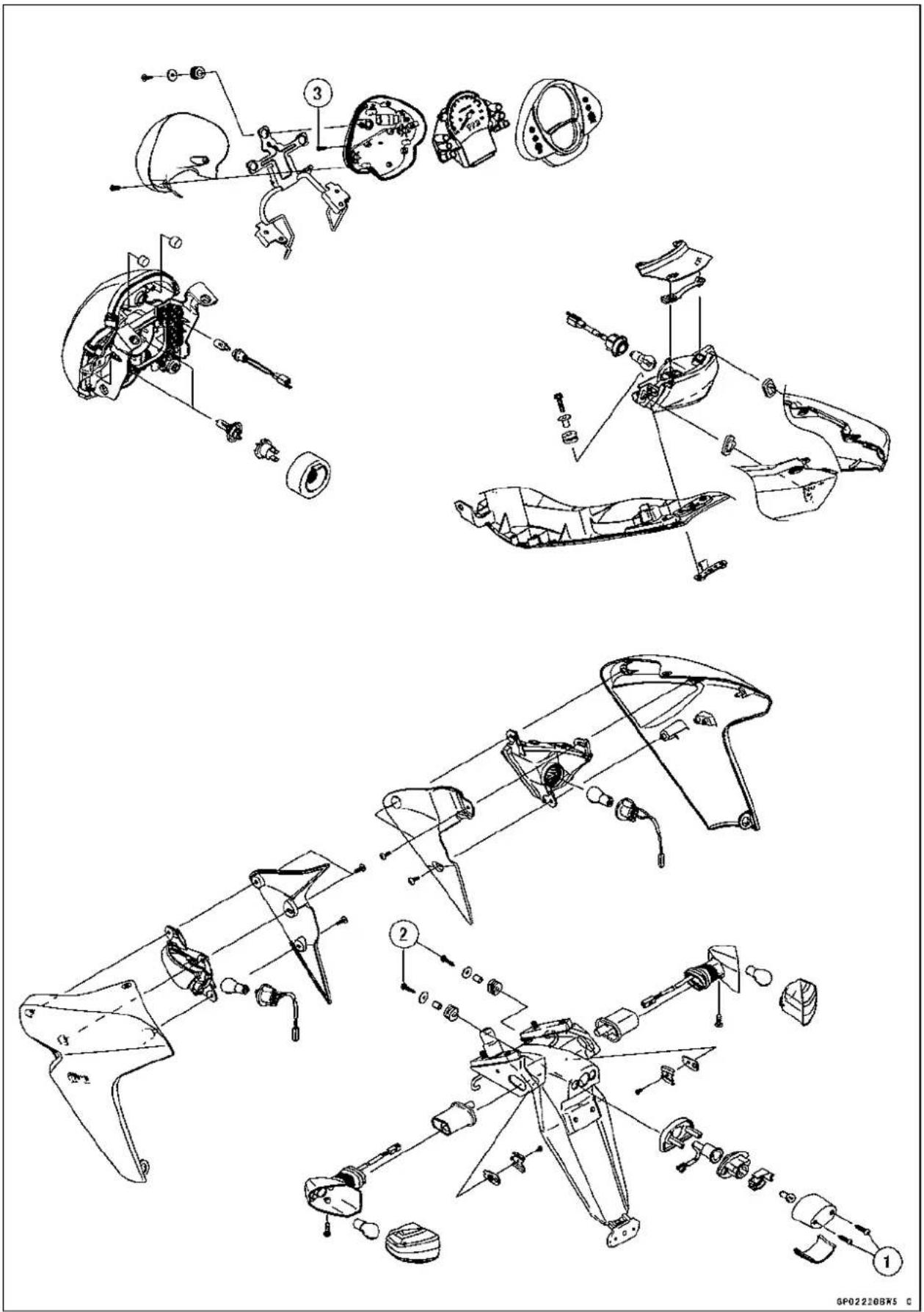
ExplodedView
| No.Fastener | Torque | Remarks | |||
| N·mkgf | ·mft·lb | ||||
| 1LicensePlateLightCoverScrews0.900.0908 i n · l b | |||||
| 2LicensePlateLightMountingScrews1.20.1211in·lb | |||||
| 3 | Meter Screws | 1.2 | 0.12 | 11 in·lb | |
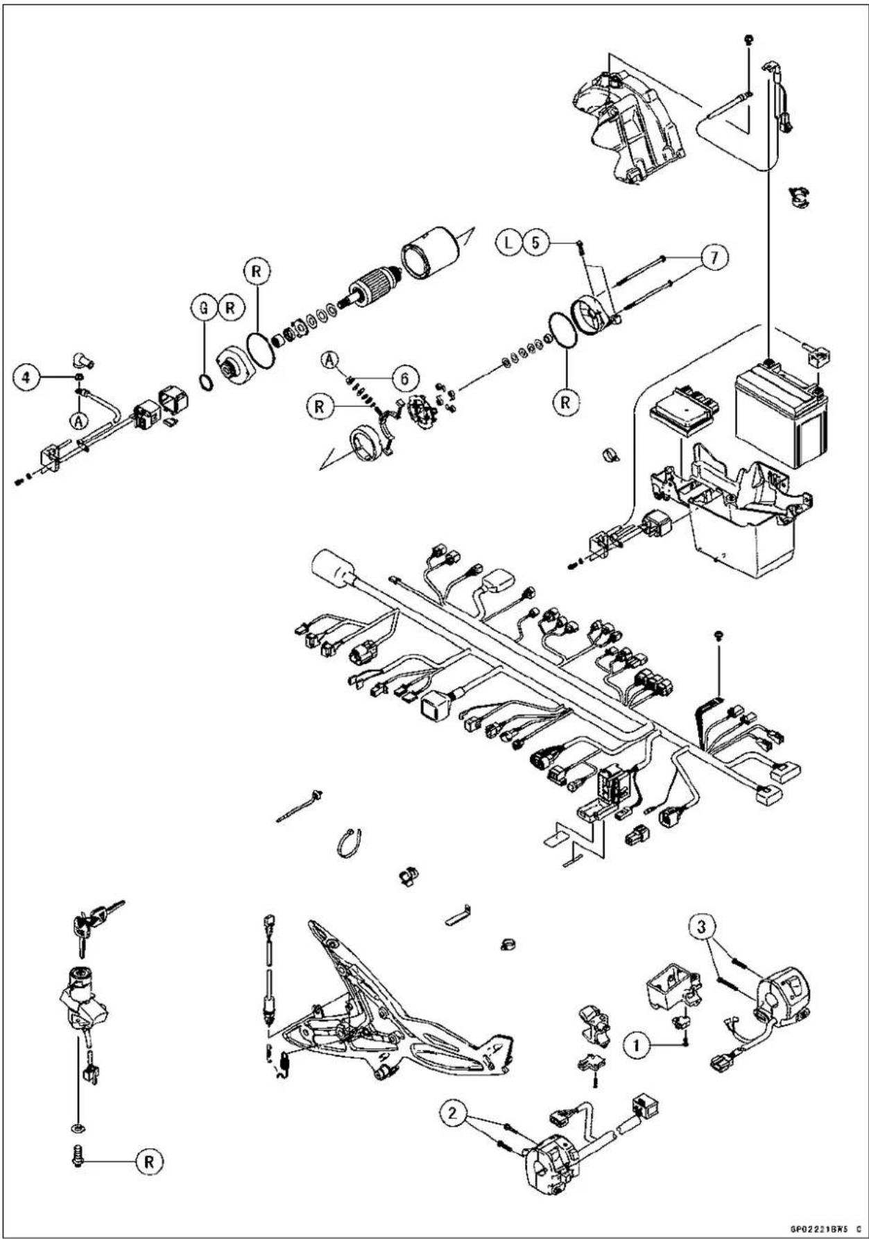
ExplodedView
| No.Fastener | Torque | Remarks | |||
| N·mkgf | mft·lb | ||||
| 1 | FrontBrakeLightSwitchScrew1.20.121in·lb | ||||
| 2 | LeftSwitchHousingScrews3.50.3631in·lb | ||||
| 3 | Right Switch Housing Screws | 3.5 | 0.36 | 31 in·lb | |
| 4 | StarterMotorCableTerminalNut | 6.00.60 | 53in·lb | ||
| 5 | Starter Motor Mounting Bolts | 9.8 | 1.0 | 87 in·lb | L |
| 6 | Starter Motor Terminal Locknut | 11 | 1.1 | 97 in·lb | |
| 7 | Starter Motor Through Bolts | 4.9 | 0.50 | 43 in·lb | |
G: Applygrease.
L: Applyanon-permanentlockingagent.
R: ReplacementParts
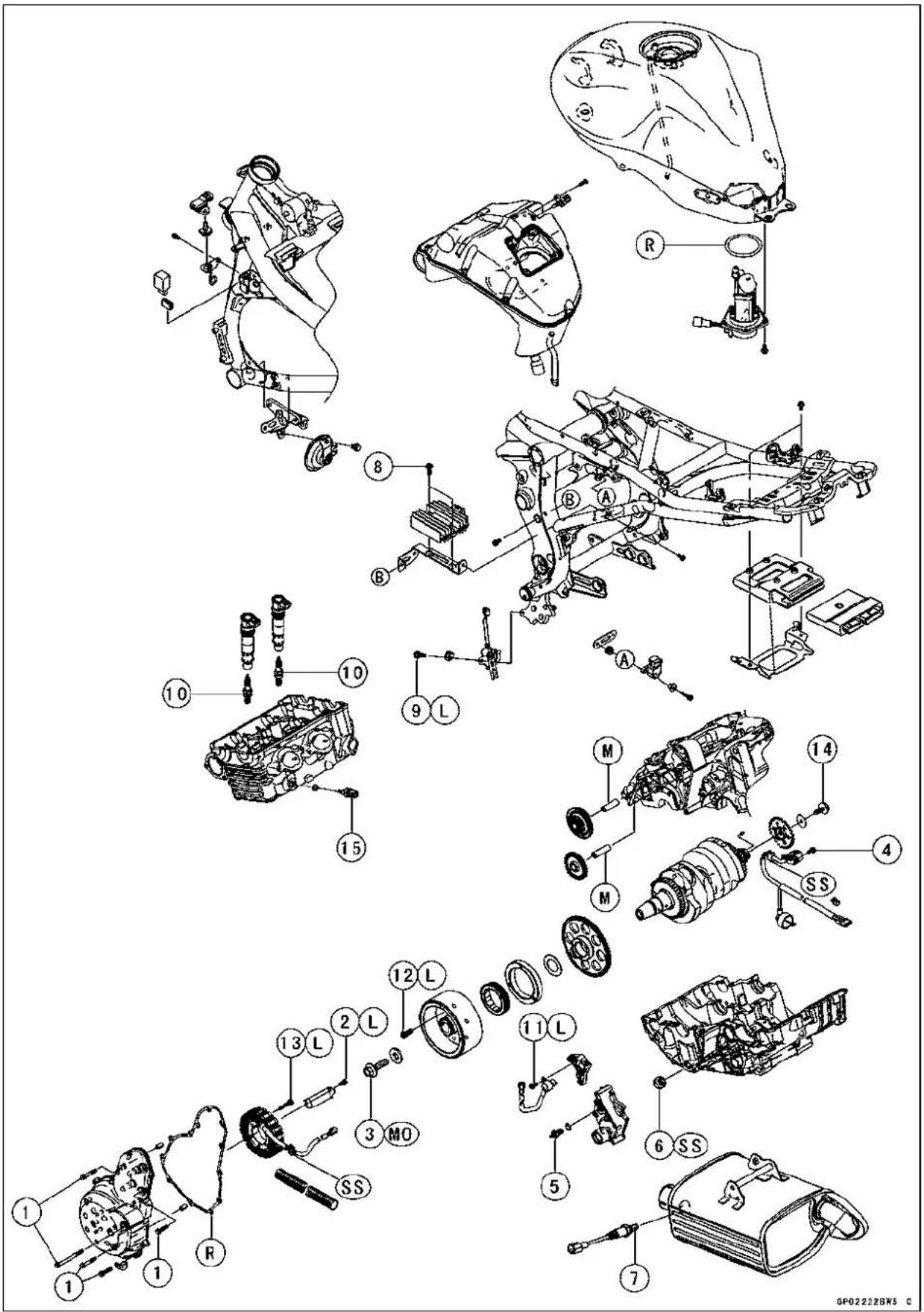
ExplodedView
| No. | Fastener | Torque | Remarks | ||
| N·mkgf | ·mft·lb | ||||
| 1 | AlternatorCoverBolts9.81.087in·lb | ||||
| 2 | Alternator Lead Holding Plate Bolt | 9.8 | 1.0 | 87 in·lb | L |
| 3 | Alternator Rotor Bolt | 155 | 15.8 | 114 | MO |
| 4 | Crankshaft Sensor Bolts | 6.0 | 0.60 | 53 in·lb | |
| 5 | Neutral Switch | 15 | 1.5 | 11 | |
| 6 | Oil Pressure Switch | 15 | 1.5 | 11 | SS |
| 7 | OxygenSensor | 44.1 | 4.50 | 32.5 | |
| 8 | Regulator/Rectifier Bolts | 8.8 | 0.90 | 78 in·lb | |
| 9 | Sidestand Switch Bolt | 8.8 | 0.90 | 78 in·lb | L |
| 10 | Spark Plugs | 15 | 1.5 | 11 | |
| 11 | Speed Sensor Bolt | 7.8 | 0.80 | 69 in·lb | L |
| 12 | Starter Motor Clutch Bolts | 34 | 3.5 | 25 | L |
| 13 | StatorCoilBolts | 12 | 1.2 | 106 in·lb | L |
| 14 | Timing Rotor Bolt | 40 | 4.1 | 30 | |
| 15 | Water Temperature Sensor | 12 | 1.2 | 106 in·lb | |
L: Applyanon-permanentlocking agent.
M:Applymolybdenumdisulfidegrease.
MO:Applymolybdenumdisulfideoil solution.
(Mixtureoftheengineoilandmolybdenumdisulfidegreaseinaweightratio10:1)
R:ReplacementParts
SS:Applysilicone sealant.
Specifications
| ItemStandard | |
| BatteryTypeModelNameYTX12-BSCapacity12V10AhVoltage12.8Vormore | SealedBattery |
| ChargingSystemTypeThree-phaseACAlternatorOutputVoltage42Vormoreat4000r/min(rpm)StatorCoilResistance0.18~ 0.27ΩChargingVoltage14.2~ 15.2V(Regulator/RectifierOutputVoltage) | |
| IgnitionSystemCrankshaft Sensor ResistanceCrankshaftSensorPeakVoltageStickCoil:Primary Winding ResistanceSecondary Winding ResistancePrimaryPeakVoltageSparkPlug:Spark Plug Gap | 376 ~ 564 Ω1.9Vormore1.1 ~ 1.5 Ω10.8 ~ 16.2 kΩ88Vormore0.8 ~ 0.9 mm (0.03 ~ 0.04 in.) |
| ElectricStarterSystemStarterMotor:BrushLengthCommutator Diameter | 12mm(0.47in.)(Servicelimit:6.0mm,0.24in.)28 mm (1.10 in.) (Service limit: 27 mm, 1.06 in.) |
| AirSwitchingValveResistance | 18~ 22Ω at20°C(68°F) |
| SwitchandSensorRear Brake Light Switch TimingEngine Oil Pressure Switch ConnectionsWater Temperature Sensor Resistance | ON after about 10 mm (0.39 in.) pedal travelWhen engine is stopped: ONWhenengineisrunning: OFFin the text |
SpecialToolsandSealants
HandTester: 57001-1394
natural_image
Technical line drawing of a mechanical housing or enclosure with internal components and mounting holes (no text or symbols)FlywheelPullerAssembly, M38×1.5/M35×1.5: 57001-1405
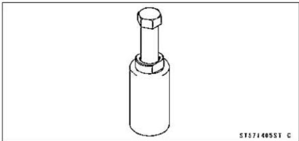
natural_image
Technical line drawing of a mechanical component with a cylindrical body and hexagonal top (no text or symbols)PeakVoltageAdapter: 57001-1415

natural_image
Simple line drawing of a coiled electrical component with two probes and a rectangular block (no text or symbols)LeadWire-PeakVoltageAdapter: 57001-1449

natural_image
Pure electrical connector diagram without any text, numbers, or symbolsNeedleAdapterSet: 57001-1457

natural_image
Technical line drawing of two screwdriver tips (no text or symbols)Grip: 57001-1591

natural_image
Technical line drawing of a metal bracket with two bolts and a hole, no text or symbols presentFlywheel&PulleyHolder: 57001-1605

natural_image
Technical line drawing of a mechanical bracket assembly with mounting holes and mounting points (no text or symbols)RotorHolder: 57001-1658

natural_image
Technical line drawing of two mechanical components: a circular ring with flange and a hexagonal nut (no text or symbols)KawasakiBond(SiliconeSealant): 56019-120

KawasakiBond(SiliconeSealant): 92104-0004

PartsLocation


-
AirSwitchingValve
-
Alternator
3.Battery12V10Ah
4.CrankshaftSensor
5.ECU(ElectricControlUnit)
6.FanMotor
7.FrontBrakeLightSwitch
8.FuseBoxwithECUMainFuse
9.IgnitionSwitch
10.MeterUnit
- NeutralSwitch
12.OilPressureSwitch
13.RearBrakeLightSwitch
14.Regulator/Rectifier
15.RelayBox
16.SidestandSwitch
17.SpeedSensor
18.StarterLockoutSwitch
19.StarterMotor
20.StarterRelaywithMainFuse
21.StickCoils
22.TurnSignalRelay
23.WaterTemperatureSensor
24.OxygenSensor(EuropeModels)
PartsLocation
DummyPage
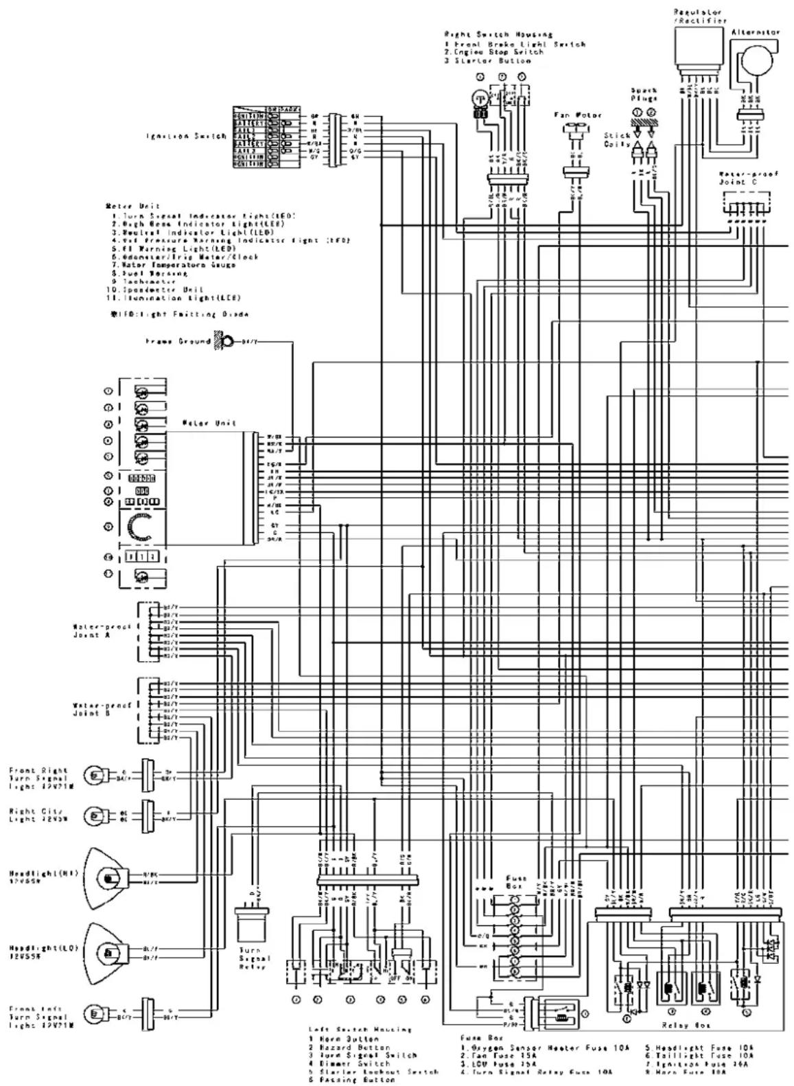
| LEFT SWITCH HOUSING CONNECTIONS | ||||||||||||||||||||
| Horn Button | Hazard Button | Turn Signal Switch | Dinner Switch | Starter Lockout Switch | Passing Button | |||||||||||||||
| Color | BK/W | BK/Y | Color | G | O | GY | Color | G | O | GY | Color | R/BK | BL/Y | R/Y | Color | BK | BK/R | Color | R/BK | BL/Y |
| L | HI | Clutch tear | ||||||||||||||||||
| Push | Push | OFF (Push) | Released | Push | ||||||||||||||||
| OFF (Push) | R | LO | Pulled in | |||||||||||||||||
T2L0221AH5 C
WiringDiagram

Precautions
Thereareanumberofimportantprecautionsthatare mustswhenservicingelectricalsystems.Learnandobservealltherulesbelow.
- Donotreversethebatterycableconnections. This will burnoutthediodesontheelectricalparts.
○Alwayscheckbatteryconditionbeforecondemningother partsofanelectricalsystem.Afullychargedbatteryisa mustforconductingaccurateelectricalsystemtests.
○Theelectricalpartsshouldneverbestrucksharply,as withahammer,orallowedtofallonahardsurface.Such ashocktothepartscandamagethem. - Toppreventdamagetoelectricalparts,donotdisconnect thebatterycablesoranyotherelectricalconnections whentheignitionswitchison,orwhiletheengineis running.
○Becauseofthelargeamountofcurrent,neverkeepthe starterbuttonpushedwhenthestartermotorwillnotturn over,orthecurrentmayburnoutthestartermotorwindings. - Donotuseameterilluminationbulbratedforotherthan voltageorwattagespecifiedinthewiringdiagram,asthe meterorgaugepanelcouldbewarpedbyexcessiveheat radiatedfromthebulb.
○Takecarenottoshortthecablesthataredirectlyconnectedtothebatterypositive(+)terminaltothechassis ground.
○Troublesmayinvolveoneorinsomecasesallitems. Neverreplaceadefectivepartwithoutdeterminingwhat CAUSEDthefailure.Ifthefailurewascausedbysome otheritemoritems,theymustberepairedorreplaced,or thenewreplacementwillsoonfailagain.
○Makesureallconnectorsinthecircuitarecleanandtight, andexaminewiresforsignsofburning,fraying,etc.Poor wiresandbadconnectionswillaffectelectricalsystemoperation.
○Measurecoilandwindingresistancewhenthepartiscold (atroomtemperature).
○ColorCodes:
BK:Black
BL:Blue
BR:Brown
CH:Chocolate
DG:DarkGreen
G:Green
GY:Gray
LB:LightBlue
LG:LightGreen
O:Orange
P:Pink
PU:Purple
R:Red
W:White
Y:Yellow
○ElectricalConnectors FemaleConnectors[A]

Precautions
MaleConnectors[B]

- Visuallyinspectthewiringforsignsofburning,fraying, etc.
★Ifanywiringispoor,replacethedamagedwiring. - Pulleachconnector[A]apartandinspectitforcorrosion, dirt, and damage.
★Iftheconnectoriscorrodedordirty,cleanitcarefully.Ifit isdamaged,replaceit. - Checkthewiringforcontinuity.
OUsethewiringdiagramtofindtheendsoftheleadwhich issuspectedofbeingaproblem.
○Connectthehandtesterbetweentheendsoftheleads.
SpecialTool-HandTester:57001-1394
○Setthetestertothe×1Ω range,andreadthetester.
★Ifthetesterdoesnotread0Ω, theleadisdefective. Re-placetheleadorthewiringharness[B]ifnecessary.
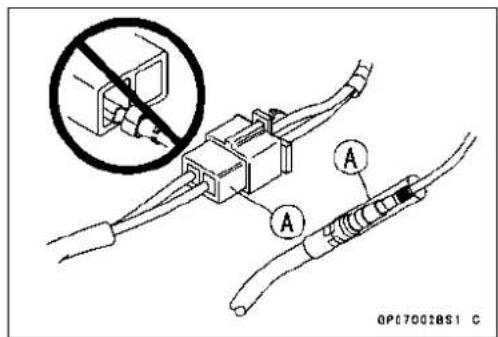

natural_image
Technical line drawing of a mechanical assembly with multiple connectors and a labeled component (B), no readable text or symbols present.Battery
BatteryRemoval
- Remove: Seat(seeSeatRemovalintheFramechapter)
- Disconnectthenegative(−)cable[A].
- Slideoutthepositive(+)terminalcap[B]andthendisconnectthepositive(+)cable.
CAUTION
Besuretodisconnectthenegative(−)cablefirst.
- Removethebattery.
Battery Installation
- Putthebatteryintotherearfenderfront.
- Applyalightcoatofgreaseontheterminalstoprevent corrosion.
• Installthepositive(+)cable[A]first. - Coverthepositive(+)terminalwiththecap[B].
- Installthenegative(−)cable[C].
BatteryActivation
ElectrolyteFilling
- Makesurethatthemodelname[A]oftheelectrolytecontainermatchesthemodelname[B]ofthebattery. These namesmustbethesame.
BatteryModelNameforER650A:YTX12-BS
CAUTION
Besuretousetheelectrolytecontainerwiththe samemodelnameasthebatterysincetheelectrolytevolumeandspecificgravityvarywiththe batterytype.Thisistopreventoverfillingofthe electrolyte,shortingthebatterylife,anddeteriorationofthebatteryperformance.
CAUTION
Donotremovethealuminumsealingsheet[A]from thefillerports[B]untiljustpriortouse.Besureto usethededicatedelectrolytecontainerforcorrect electrolytevolume.
- Placethebatteryonalevelsurface.
- Checktoseethatthesealingsheethasnopeeling, tears, orholesinit.
- Removethesealingsheet.


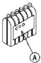

natural_image
Isometric line drawing of a battery with mounting holes and a labeled component (B), no text or symbols present.QP180204S1 C
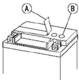
OP18003BS1 C
NOTE
○ Thebatteryisvacuumsealed. If thesealingsheethas leakedairintothebattery, it may require alonger initial charge.
Battery
- Removetheelectrolytecontainerfromthevinylbag.
- Detachthestripofcaps[A]fromthecontainerandset aside,thesewillbeusedlatertosealthebattery.
NOTE
○ Donotpierceorotherwiseopenthesealedcells[B] of theelectrolytecontainer.Donotattemptoseparate individualcells.
- Placethelectrolytecontainerupsidedownwiththesix sealedcellsintothefillerportsofthebattery.Holdthe containerlevel,pushdowntobreakthesealsofallsix cells.Youwillseeairbubblesrisingintoeachcellasthe portsfill.
NOTE
○ Donottilttheelectrolytecontainer
- Checktheelectrolyteflow.
★Ifnoairbubbles[A]arecomingupfromthefillerports,or ifthecontainercellshavenotemptiedcompletely,tapthe container[B]afewtimes. - Keepthecontainerinplacefor20minutesormore. Don't removethecontainerfromthebatteryuntil'sempty, the batteryrequiresalltheelectrolytefromthecontainerfor properoperation.
CAUTION
Removalofthecontainerbeforeitiscompletely emptycanshortentheservicelifeofthebattery.Do notremovetheelectrolytecontaineruntilitiscom- pletelyemptyand20minuteshaveelapsed.
- Gentlyremovethecontainerfromthebattery.
- Letthebatterysitfor30minutespriortochargingtoallow theelectrolytetopermeateintotheplatesforoptimum performance.
NOTE
○ Chargingthebatteryimmediatelyafterfillingcan shortenservicelife.Letthebatterysitforatleast30 minutesafterfilling.


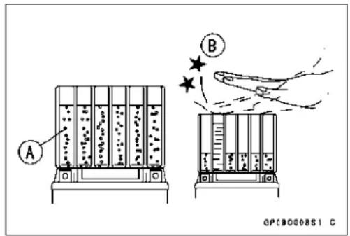
Battery
InitialCharge
- Placethestrip[A]ofcapslooselyoverthefillerports.
- Newlyactivatedsealedbatteriesrequireaninitialcharge.
StandardCharge: 1.2A×5\~10hours
★Ifusingarecommendedbatterycharger, followthe charger'sinstructionsfornewlyactivatedsealedbattery.
Kawasaki-recommendedchargers
Optimatell
Yuasa1.5AmpAutomaticCharger
BatteryMate150-9
★ Iftheabovechargersarenotavailable,useequivalent one.
NOTE
○Chargingrateswillvarydependingonhowlongthe batteryhasbeenstored,temperature,andthetypeof chargerused.Letbatterysit30minutesafterinitial charge,thencheckvoltageusingavoltmeter.Ifitis notatleast12.8V,repeatchargingcycle.
- Afterchargingiscompleted, pressdownfirmlywithboth handstoseatthestripofcaps[A]intothebattery(don't poundorhammer.). Whenproperlyinstalled, thestripof thecapswillbelevelwiththetopofthebattery.
CAUTION
Oncethestripofthecaps[A]isinstalledontothe battery,neverremovethecaps,noraddwaterorelectrolytetothebattery.


natural_image
Technical line drawing of a battery and its internal components with no visible text or symbolsNOTE
Toensuremaximumbatterylifeandcustomersatisfaction, it is recommended the battery beload tested at threetimesitsamp-hour rating for 15 seconds. Re-check voltage and if less than 12.8 V repeat the charging cycle and load test. If still below 12.8 V the battery is defective.
Battery
Precautions
1) Noneedoftopping-up
Notopping-upisnecessaryinthisbatteryuntilitendsitslifeundernormaluse.F offthesealcaptoaddwaterisverydangerous.Neverdothat.
orciblyprying
2) Refreshingcharge.
Ifanenginewillnotstart,ahornsoundsweak,orlampsaredim,itindicatesthebatteryhasbeen discharged.Giverefreshchargefor5to10hourswithchargecurrentshowninthespecification (seeSpecifications).
When a fast charge is inevitably required, do it following precisely the maximum charge current and time conditions indicated on the battery.
CAUTION
Thisbatteryisdesignedtosustainnounusualdeteriorationifrefresh-chargedaccording tothemethodspecifiedabove.H _owever,thebattery'sperformancemaybereducednoticeablyifchargedunderconditionsotherthangivenabove.Neverremovethesealcap duringrefreshcharge.
If by chance an excessive amount of gas is generated due to overcharging, thereelief valve releases the gastokee the battery normal.
3) When you donotus the motorcycle form months.
Give are fresh charge before you store them motorcycle and store it with the negative cabler removed. Give a refresh charge once a month during storage.
4) Batterylife.
If the battery will not start the engine even after several refresh charges, the battery has exceeded its use full life. Replace it (Provided, however, the vehicle's startingsystem has no problem).
WARNING
Keepthebatteryawayfromsparksandopenflamesduringcharging,sincethebattery givesoffanexplosivegasmixtureofhydrogenandoxygen.Whenusingabatterycharger, connectthebatterytothechargerbeforeturningonthecharger.
This procedure preventssparksatthebatteryterminals which could ignite any battery gases.
Nofireshouldbedrawnnearthebattery,ornoterminalsshouldhavethetighteningloosened.
Theelectrolytecontainssulfuricacid.Becarefulnottohaveittouchyourskinoreyes.If touched,washitoffwithliberalamountofwater.Getmedialattentionifsevere.
Interchange
Asealed battery can fully display its performance only when combined with a proper vehicle electric system. Therefore, replace a sealed battery only on a motorcycle which was originally equipped with a sealed battery.
Becareful, ifasealedbattery is installed on a motorcycle which had an ordinary battery as original equipment, thesealedbattery's lifewill beshortened.
Battery
ChargingConditionInspection
○Batterychargingconditioncanbecheckedbymeasuring batteryterminalvoltagewithadigitalvoltmeter[A].
- Remove:
Seat(seeSeatRemovalintheFramechapter) BatteryCableCap(seeBatteryRemoval)
- Disconnectthebatteryterminals.
CAUTION
Besuretodisconnectthenegative(−)cablefirst.
- Measurethebatteryterminalvoltage.
NOTE
○Measurewithadigitalvoltmeterwhichcanbereadone decimalplacevoltage.
★ Ifthereadingis12.8Vormore, norefreshchargeisrequired, however, ifthereadisbelowthespecified, refresh chargeisrequired.
BatteryTerminalVoltage
Standard: 12.8Vormore
TerminalVoltage(V)[A]
BatteryChargeRate(%)[B]
Good[C]
Refreshchargeisrequired[D]
RefreshingCharge
- RemovethebatteryA.
- Dorefreshchargebyfollowingmethodaccordingtothe batteryterminalvoltage.
WARNING
Thisbatteryissealedtype.Neverremovesealing cap[B]evenatcharging.Neveraddwater.Charge withcurrentandtimeasstatedbelow.


line
| X (%) | Y | |---|---| | 100 | 13.2 | | 90 | 13.1 | | 80 | 13.0 | | 70 | 12.9 | | 60 | 12.8 | | 50 | 12.7 | | 40 | 12.6 | | 30 | 12.5 | | 20 | 12.4 | | 10 | 12.3 | | 0 | 12.2 | The chart displays a single decreasing trend line from point A (100, 13.2) to point B (0, 12.1). The label 'A' and 'B' are present at the top left, while 'C' and 'D' are positioned below the graph.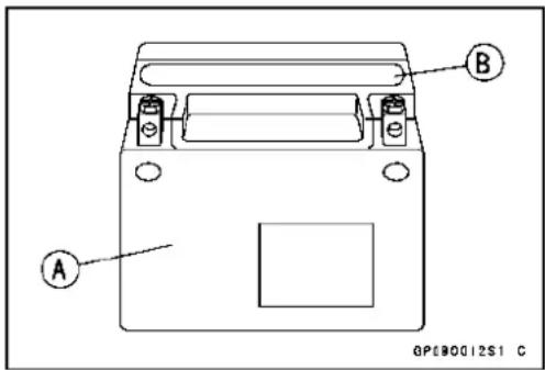
Battery
TerminalVoltage:11.5\~ lessthan12.8V
StandardCharge1.2A×5\~ 10h(seefollowingchart)
QuickCharge 5 A × 1 h
CAUTION
If possible, donot quick charge. If quick charge is done unavoidably, dostandard chargelateron.
TerminalVoltage:lessthan11.5V
ChargingMethod 1.2 A × 20 h
NOTE
○ Increase the charging voltage to a maximum voltage of 25V if the battery will not accept current initially. Charge for more than 5 minutes at the increased voltage then check if the battery is drawing current. If the battery will accept current decrease the voltage and charge by the standard charging method described on the battery case. If the battery will not accept current after 5 minutes, replace the battery.
Battery[A]
BatteryCharger[B]
StandardValue[C]
- Determinethebatteryconditionafterrefreshcharge.
○Determinetheconditionof thebatteryleftfor30minutes aftercompletionofthechargebymeasuringtheterminal voltageaccording to thetable below.
| Criteria | Judgement |
| 12.8 Vor higher | Good |
| 12.0 ~ lower than 12.8 V | Chargeinsufficient→ Recharge |
| lower than 12.0 V | Unserviceable → Replace |

line
Charge Time (h) | Battery Terminal Voltage (V) | Charge Time (h) | | :--- | :--- | | 11.6 | 10 | | 11.8 | 8 | | 12.0 | 6 | | 12.2 | 4 | | 12.4 | 2 | | 12.6 | 0 | | 12.8 | -2 | | 13.0 | -4 |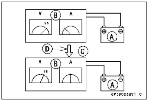
flowchart
graph TD
    A["Switch A"] --> B["Diode D"]
    B --> C["Switch C"]
    C --> D["Power Supply"]
    subgraph Power Source
        E["16μF"] --> F["Ground"]
        G["25μF"] --> H["Ground"]
    end
    style E fill:#f9f,stroke:#333
    style F fill:#ccf,stroke:#333
    style G fill:#cfc,stroke:#333
    note right of E: 25μF (green arc) or 16μF (red arc)
    note right of G: 16μF (green arc) or 25μF (red arc)
ChargingSystem
AlternatorCoverRemoval
- Remove:
LowerFairing(seeLowerFairingRemovalintheFrame chapter)
AlternatorLeadConnector[A]
- Placeasuitablecontainerunderthealternatorcover[A], andremovethecoverbolts[B].
- Pullthealternatorcoveroutside.

natural_image
Close-up mechanical assembly showing a brake caliper and suspension components (no visible text or symbols)
AlternatorCoverInstallation
- Applysiliconesealanttothealternatorleadgrommetand crankcasehalvesmatingsurface[A]onthefrontandrear sidesofthecovermount.
Sealant-KawasakiBond(SiliconeSealant):92104-0004
- Checkthatdowelpins[B]areinplaceonthecrankcase.
• Installanewgasketandthealternatorcover. - Tighten:
Torque-AlternatorCoverBolts:9.8N·m(1.0kgf·m,87in·lb)


StatorCoilRemoval
- Remove:
AlternatorCover(seeAlternatorCoverRemoval) HoldingPlateBolt[A]andPlate
AlternatorLeadGrommet[B] StatorCoilBolts[C]
- Removethestatorcoil[D]fromthealternatorcover.
ChargingSystem
StatorCoilInstallation
- Applyanon-permanentlockingagenttothethreadsof thestatorcoilboltsandtightenthem.
Torque-StatorCoilBolts:12N·m(1.2kgf·m,106in·lb)
- Securethealternatorleadwithaholdingplate, and tightenthebolt.
○Applyanon-permanentlockingagenttothethreadsof theholdingplatebolt.
Torque-AlternatorLeadHoldingPlateBolt:9.8N·m(1.0 kgf·m,87in·lb)
- Applysilicones equalant to the circumference of the alternator lead grommet, and fitthegrommet into thenotch of the cover securely.
Sealant-KawasakiBond(SiliconeSealant):92104-0004
- Installthealternatorcover(seeAlternatorCoverInstallation).
AlternatorRotorRemoval
- Removethealternatorcover(seeAlternatorCoverRemoval).
- Removethestarteridlegear, torquelimiterandshafts.
- Wipeoilofftheoutercircumferenceoftherotor.
- Holdthealternatorrotorsteadywiththerotorholder[A], andremovetherotorbolt[B]andwasher.
SpecialTools-Grip:57001-1591
RotorHolder:57001-1658
- Usingtheflywheelpuller[A],removethealternatorrotor fromthecrankshaft.
SpecialTool-FlywheelPullerAssembly, M38×1.5/M35×1.5:57001-1405
CAUTION
Donotattempttostrikethealternatorrotoritself. Strikingtherotorcancausethemagnetstolose theirmagnetism.
AlternatorRotorInstallation
- Usingacleaningfluid,cleanoffanyoilordirtonthefollowingportionsanddrythemwithacleancloth.
CrankshaftTaperedPortion[A]
AlternatorRotorTaperedPortion[B]
- Applyathincoatofmolybdenumdisulfidegreasetothe crankshaft[C].
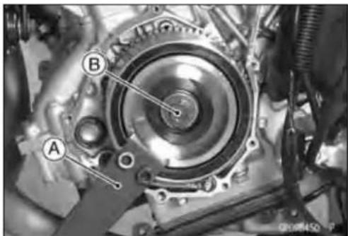

natural_image
Mechanical gear assembly with labeled component A (no readable text or symbols)
natural_image
Technical drawing of a mechanical component with cross-sectional view and labeled section B (no text or symbols beyond label)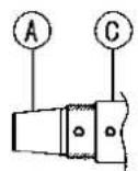
GP09141851 C
ChargingSystem
• Installthestartergear[A]andwasher[B].
- Again, cleanthecrankshaft tapered portion [C] and dry there.
- Installthealternatorrotor[A]whileturning[B]itcounterclockwise.
- Installthewasher[A].
NOTE
○Confirmthealternatorrotorfitornottothecrankshaft beforetighteningitwithspecifiedtorque.
- Applymolybdenumdisulfideoilsolutiontothethreads andseatingsurfaceoftherotorbolt.
- Installtherotorbolt[B]andtightenitwith70N·m(7.0 kgf·m,52ft·lb)oftorque.
- Removetherotorboltandwasher.
- Checkthetighteningtorquewithflywheelpuller.
★ Iftherotoris not pulled out with 20N·m (2.0kgf·m, 15 ft·lb) of drawing torque, it is installed correctly.
★Iftherotorispulledoutwithunder20N·m(2.0kgf·m,15ft·lb)ofdrawingtorque,cleanoffanyoidirtorflawofthecrankshaftandrotortaperedportion,anddrythemwithacleancloth.Then,confirmthatitisnotpulledoutwithabovetorque. - Tightenthealternatorrotorboltwhileholdingthealternatorrotorsteadywiththerotorholder.
SpecialTools-Grip:57001-1591
RotorHolder:57001-1658
Torque-AlternatorRotorBolt:155N·m(15.8kgf·m,114ft·lb)

ChargingSystem
- Applyathincoatofmolybdenumdisulfidegreasetothe shafts[A], and install them.
• Installthetorquelimiter[B]andstarteridlegear[C]. - Installthealternatorcover(seeAlternatorCoverInstallation).
AlternatorInspection
Therearethreetypesofalternatorfailures:short,open (wireburnedout),orlossinrotormagnetism.Ashortor openinoneofthecoilwireswillresultineitheralowoutput,ornooutputatall.Alossinrotormagnetism,whichmaybe causedbydroppingorhittingthealternator,byleavingit nearanelectromagneticfield,orjustbyaging,willresultin lowoutput.
- Tocheckthealternatoroutputvoltage,dothefollowing procedures.
○Turnofftheignitionswitch.
○Disconnectthealternatorleadconnector[A].
○Connectthehandtesterasshowninthetable1.
○Starttheengine.
○Runitatherpmgiveninthetable1.
○Notethevoltagereadings(total3measurements).
Table1 AlternatorOutputVoltage
| Tester Range | Connections | Reading at4000rpm | |
| Tester(+)toTester(-)to | |||
| 250VACOne | Blacklead | Another Blacklead42 | Vormore |
★ If the output voltages show the value in the table, the alternator operates properly.
★Iftheoutputvoltageshowsamuchhigherthanthevalueinthetable,theregulator/rectifierisdamaged. Amuch lowerreadingthanthatgiveninthetableindicatesthat thealternatorisdefective.
- Checkthestatorcoilresistanceasfollows.
○Stoptheengine.
○Connectthehandtesterasshowninthetable2.
○Notethereadings(total3measurement).
Table2StatorCoilResistance
| Tester Range | Connections | Reading | |
| Tester(+)toTester(-)to | |||
| ×1Ω | OneBlacklead | AnotherBlacklead | 0.18~0.27Ω |


natural_image
Mechanical assembly diagram showing components like gears and springs (no readable text or symbols)ChargingSystem
★ Ifthereismoreresistancethanshowninthetable,orno handtesterreading(infinity)foranytwoleads,thestator hasanopenleadandmustbereplaced.Muchlessthan thisresistancemeansthestatorisshorted,andmustbe replaced.
- Using the highest resistancer range of the hand tester, measure the resistance between each of the black leads and chassis ground.
★Anyhandtesterreadinglessthaninfinity(∞)indicatesa short, necessitatingstatorreplacement.
★ Ifthestatorcoilshavenormalresistance, but the voltage check showed the alternatortobedefective; then therotor magnet shave probably weakened, and therotormust be replaced.
SpecialTool-HandTester:57001-1394
Regulator/RectifierInspection
- Remove: Bolts[A]
- Disconnecttheconnector[A].
- Removetheregulator/rectifier[B].

natural_image
Close-up of a car interior showing a metallic heating element labeled 'A' (no readable text or symbols beyond the label)
RectifierCircuitCheck
- Checkconductivityofthefollowingpairofterminals.
RectifierCircuitInspection
★The resistance should be low in one direction and more thantentimesasmuchintheotherdirection. Ifanytwo leadsareloworhighinbothdirections,therectifieris defectiveandtheregulator/rectifiermustbereplaced.

NOTE
○Theactualmeterreadingvarieswiththemeterused and the individual rectifier, but, generally speaking the lowerreadingsshouldbefromzerotoonehalfthescale.
ChargingSystem
RegulatorCircuitCheck
Totesttheregulatoroutofcircuit, usethree12Vbatteries andatestlight(12V3\~6Wbulbinasocketwithleads).
CAUTION
Thetestlightworksasanindicatorandalsoacurrentlimitertoprotecttheregulator/rectifierfromexcessivecurrent.Donotuseanammeterinsteadof atestlight.
- Checktobesuretherectifiercircuitisnormalbeforecontinuing.
- Dothe1ststepregulatorcircuittest.
○Connectthetestlightandthe12Vbatterytotheregulator/rectifierasshown.
○ChecktheBK1,BK2andBK3terminalrespectively.
★Ifthetestlightturnson,theregulator/rectifierisdefective. Replaceit.
★Ifthetestlightdoesnotturnon,continuethetest.
- Dothe2ndstepregulatorcircuittest.
○Connectthetestlightandthe12Vbatteryinthesame mannerasspecifiedinthe“RegulatorCircuitTest-1st Step”.
○Apply12VtothevoltageBRterminal.
○ChecktheBK1,BK2andBK3terminalrespectively.
★Ifthetestlightturnson,theregulator/rectifierisdefective. Replaceit.
★Ifthetestlightdoesnotturnon,continuethetest.
- Dothe3rdstepregulatorcircuittest.
○Connectthetestlightandthe12Vbatteryinthesame mannerasspecifiedinthe“RegulatorCircuitTest-1st Step”.
- Momentarilyapply24VtothevoltageBRterminalby addinga12Vbattery.
○ChecktheBK1,BK2andBK3terminalsrespectively.
CAUTION
Donotapplymorethan24V.Ifmorethan24Visapplied,theregulator/rectifiermaybedamaged.Do notapply24Vmorethanafewseconds.If24V isappliedformorethanafewseconds,theregulator/rectifiermaybedamaged.
★Ifthetestlightdidnotlightwhenthe24Vwasapplied momentarilytothevoltagemonitoringterminal,theregulator/rectifierisdefective.Replaceit.
★Iftheregulator/rectifierpassesallofthetestsdescribed, itmaystillbedefective. Ifthechargingsystemstilldoes notworkproperlyaftercheckingallofthecomponents andthebattery,testtheregulator/rectifierbyreplacingit withaknowngoodunit.

natural_image
Pure electrical circuit lines without any symbols
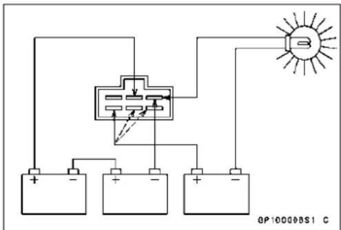
ChargingSystem
Charging Voltage Inspection
- Checkthebatterycondition(seeChargingConditionInspection).
- Warmuptheenginetoobtainactualalternatoroperating conditions.
- Removetheseat(seeSeatRemovalintheFramechapter).
- Check that the ignition switch is turned off, and connect the hand tester[A] to the battery terminals[B].
SpecialTool-HandTester:57001-1394
- Starttheengine, and not the voltage readings at various enginespeeds with the headlight turned on and then turned off (Toturnoff the headlight, disconnect the headlight connector on the headlight unit.). The reading should show nearly battery voltage when the enginespeed is slow, and, astheenginespeed rises, the reading should also rise. But they must be kept under the specified voltage.
ChargingVoltage
| TesterRange | Connections | Reading | |
| Tester(+) to Tester(-) to | |||
| 25 V DC | Battery (+) | Battery (-) | 14.2 ~ 15.2 V |
- Turn off the ignition switch to stop the engine, and disconnectthehandtester.
★If the charging voltage is kept between the values given in the table, the charging system is considered to be working normally.
★ If the charging voltage is much higher than the values specified in the table, theregulator/rectifier is defective or theregulator/rectifier leads are loose or open.
★If the charging voltaged does not rise as the enginespeed increases, thenteregulator/rectifier is defective or the alternator output is insufficient fortheloads. Check the alternator and regulator/rectifier to determine which part is defective.
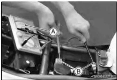
natural_image
Close-up of hands working on an automotive engine with labeled components (A and B), no visible text or symbols beyond labels.ChargingSystemCircuit

GP09144BH2 C
- IgnitionSwitch
- Alternator
- Regulator/Rectifier
- Water-proof JointC
5.MainFuse30A
6.Battery12V10Ah
7.Load
StarterMotorClutch
StarterMotorClutchRemoval/Installation
- RefertotheAlternatorRotorRemoval/Installation.
StarterMotorClutchInspection
- Remove:
AlternatorCover(seeAlternatorCoverRemoval) StarterIdleGearandTorqueLimiter Shafts
- Turnthestartermotorclutchgear[A]byhand. Thestarter motorclutchgearshouldturnclockwise[B]freely, but shouldnotturncounterclockwise[C].
★ Ifthestartermotorclutchdoesnotoperateasitshouldor ifitmakesnoise, gotothenextstep. - Disassemblethestartermotorclutch, and visually inspect the clutchparts.
★ If thereisanywornordamagedpart, replaceit.
NOTE
○Examinethestartermotorclutchgearaswell.Replace itifitwornordamaged.
StarterMotorClutchDisassembly
- Remove:
AlternatorRotor(seeAlternatorRotorRemoval) StarterMotorClutchBolts[A]
- Remove:
StarterMotorClutch[A]
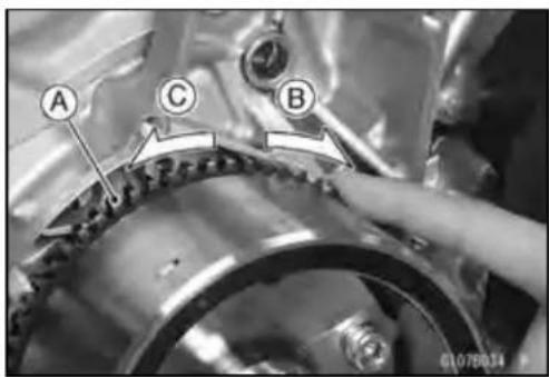

natural_image
Close-up of a metallic mechanical component with labeled points A and a small hole, no readable text or symbols present.
natural_image
Close-up of a metallic mechanical component with a labeled section A and reference number 6107B036 P (no readable text or symbols beyond label)StarterMotorClutchAssembly
- Applyanon-permanentlockingagenttothethreadsof thestartermotorclutchboltsandtightenthem.
Torque-StarterMotorClutchBolts:34N·m(3.5kgf·m,25ft·lb)
IgnitionSystem
WARNING
Theignitionsystemproducesextremelyhighvoltage.Donottouchthesparkplugsorstickcoils whiletheengineisrunning,oryoucouldreceive asevereelectricalshock.
CAUTION
Donotdisconnectthebatterycablesoranyother electricalconnectionswhentheignitionswitchis on,orwhiletheengineisrunning.Thisistoprevent ECU(ElectricControlUnit)damage. Donotinstallthebatterybackwards.Thenegative sideisgrounded.Thisistopreventdamagetothe ECU.
CrankshaftSensorRemoval
- Remove:
LowerFairing(seeLowerFairingRemovalintheFrame chapter)
RightFrameCover(seeFrameCoverRemovalinthe Framechapter)
CrankshaftSensorLeadConnector[A]
- Remove:
RubberBoot(SlideOut)[A]
OilPressureSwitchLeadTerminal[B]
ClutchCover(seeClutchCoverRemovalintheClutch chapter)
- Remove:
Bolts[A]
CrankshaftSensor[B]
- Pulloutthegrommet[C].

natural_image
Close-up mechanical assembly showing internal components and a labeled section (A), no readable text or symbols present.
natural_image
Mechanical assembly diagram showing two labeled components A and B connected to a central mechanical component (no text or symbols beyond labels)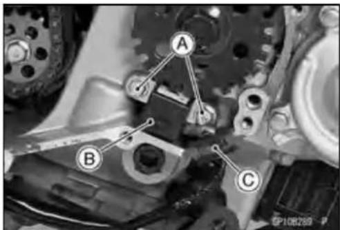
IgnitionSystem
CrankshaftSensorInstallation
- Routethecrankshaftsensorleadcorrectly(seeCable, Wire,andHoseRoutingsectionintheAppendixchapter).
- Tighten:
Torque - Crankshaft Sensor Bolts: 6.0 N·m (0.60 kgf·m, 53 in·lb)
- Applysiliconesealant[A]tothecrankshaftsensorlead grommet.
Sealant-KawasakiBond(SiliconeSealant):92104-0004
- Installtheremovedparts(seeappropriatechapters).
CrankshaftSensorInspection
- Remove:
RightFrameCover(seeFrameCoverRemovalinthe Framechapter) CrankshaftSensorLeadConnector[A]
- Setthehandtestertothe×100Ω rangeandconnect(+) leadtotheblackleadand(−)leadtotheyellowleadin theconnector.
SpecialTool-HandTester:57001-1394
★ Ifthereismoreresistancethanthespecifiedvalue,the coilhasanopenleadandmustbereplaced.Muchless thanthisresistancemeansthecoilisshorted,andmust bereplaced.
Crankshaft Sensor Resistance: 376 \~ 564 Ω
- Using the highest resistance range of the tester, measure the resistance between the crankshaft sensor leads and chassis ground.
★Anytesterreadinglessthaninfinity(∞)indicatesashort, necessitatingreplacementofthecrankshaftsensorassembly.
CrankshaftSensorPeakVoltageInspection
NOTE
○Besurethebatteryisfullycharged.
○Usingthepeakvoltageadapter[A]isamorereliable waytodeterminetheconditionofthecrankshaftsensorhancrankshaftsensorinternalresistancemeasurements.
- Remove:
CrankshaftSensorLeadConnector(seeCrankshaft SensorRemoval)
- Setthehandtester[B]tothe×DC10Vrange, and connectitpeakvoltageadapter.
- Connecttheblackleadoftheadaptertoyellowleadand redleadtoblackleadinthecrankshaftsensorconnector.
- TurntheignitionswitchandenginestopswitchON.

natural_image
Close-up mechanical assembly with labeled component A (no readable text or symbols)
natural_image
Close-up mechanical assembly showing internal components and a labeled section (A), no readable text or symbols present.
IgnitionSystem
- Pushingthestarterbutton,turntheengine4\~5 secondswiththetransmissiongearinneutraltomeasurethe crankshaftsensorpeakvoltage.
- Repeatthemeasurement5ormoretimes.
CrankshaftSensorPeakVoltage
Standard:1.9Vormore
SpecialTools-HandTester:57001-1394
PeakVoltageAdapter:57001-1415
Type:KEK-54-9-B
★ Ifthetesterreadingisnotspecifiedone, checkthecrank-shaftsensor.
TimingRotorRemoval
- Remove:
ClutchCover(seeClutchCoverRemovalintheClutch chapter)
CrankshaftSensor(seeCrankshaftSensorRemoval)
- Removethetimingrotor[A].
○Holding the timing rotor with the flywheel & pulley holder [B]andunscrewtherotorbolt[C].
Special Tool - Flywheel & Pulley Holder: 57001-1605

TimingRotorInstallation
- Fittherotortothecrankshaft.
- Tightentherotorbolt.
Torque-TimingRotorBolt:40N·m(4.1kgf·m,30ft·lb)
- Install the removed parts (see appropriate chapters).
StickCoil(IgnitionCoiltogetherwithSparkPlugCap) Removal
- Removetheaircleanerhousing(seeAirCleanerHousing Removal in the Fuel System (DFI) chapter).
- Disconnect thestickcoilconnectors [A].
- Pull the stick coils [B] off the spark plugs.
CAUTION
Donotprytheconnectorpartofthecoilwhilere-movingthecoil.
StickCoil(IgnitionCoiltogetherwithSparkPlugCap) Installation
- Insertthecoilasshownbeingcarefulofthecoilheads[A] direction.
- Connecttheconnectors.
CAUTION
Do not tap the coil head while installing the coil.
- Runthehosesandharnesscorrectly(seeCable, Wire, and Hose Routing section in the Appendix chapter).
- Install the removed parts (see appropriate chapters).

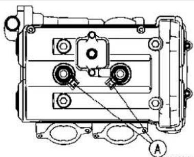
natural_image
Technical line drawing of a mechanical component with mounting holes and a central housing (no text or symbols)GP10281BS1 C
IgnitionSystem
StickCoil(IgnitionCoiltogetherwithSparkPlugCap) Inspection
- Removethestickcoils(seeStickCoil(IgnitionCoiltogetherwithSparkPlugCap)Removal).
- Measure the primary winding resistance [A] as follows.
○Connectthehandtesterbetweenthecoilterminals.
○Setthetestertothe×1Ω range,andreadthetester. - Measurethesecondarywindingresistance[B]asfollows.
○Connectthetesterbetweentheplugterminaland(−)coil terminal.
○Setthetestertothe×1kΩ rangeandreadthetester.
IgnitionCoilWindingResistance
PrimaryWindings: 1.1\~1.5Ω
Secondary Windings: 10.8 \~ 16.2 kΩ
★ Ifthetesterdoesnotreadasspecified, replacethecoil.
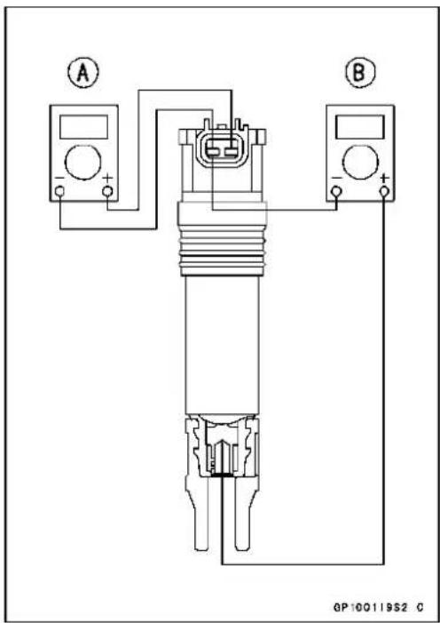
StickCoilPrimaryPeakVoltage
NOTE
○Besurethebatteryisfullycharged.
- Removethestickcoils(seeStickCoil(IgnitionCoiltogetherwithSparkPlugCap)Removal),butdonotremove thesparkplugs.
- Measure the primary peak voltage as follows.
○Installthenewsparkplug[A]intoeachstickcoil[B], and groundthemontotheengine.
○Connectthepeakvoltageadapter[C]intothehandtester[D]whichissettothe×DC250Vrange.
○Connecttheadaptertotheleadwire-peakvoltage adapter[E]whichisconnectedbetweenthestickcoil connectorandstickcoil.
ECU[F]
Battery[G]
SpecialTools-HandTester:57001-1394
PeakVoltageAdapter:57001-1415
Type:KEK-54-9-B
Lead Wire-Peak Voltage Adapter: 57001-1449
PrimaryLeadConnection
Adapter(R,+)toleadwire-peakvoltageadapter(W)
Adapter (BK, -) to lead wire-peak voltage adapter (R)
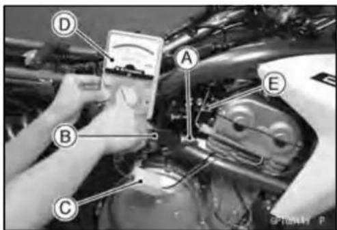

flowchart
graph TD
    A["Component A"] --> B["Valve B"]
    B --> C["Actuator C"]
    C --> D["Valve D"]
    D --> E["Component E"]
    E --> F["Valve F"]
    F --> G["Ground"]
    H["Component G"] --> I["Valve I"]
    J["Component H"] --> K["Actuator K"]
    L["Component I"] --> M["Valve M"]
    N["Component J"] --> O["Actuator O"]
    P["Component K"] --> Q["Actuator Q"]
    R["Component L"] --> S["Valve S"]
    T["Component M"] --> U["Actuator U"]
    V["Component N"] --> W["Valve W"]
    X["Component O"] --> Y["Actuator Y"]
IgnitionSystem
WARNING
Toavoidextremelyhighvoltageshocks, donot touchthesparkplugsortesterconnections.
- TurntheignitionswitchandtheenginestopswitchON.
- Pushingthestarterbutton,turntheengine4\~ 5seconds withthetransmissioninneutraltomeasuretheprimary peakvoltage.
- Repeatthemeasurements5timesforonestickcoil.
StickCoilPrimaryPeakVoltage
Standard: 88Vormore
- Repeatthetestfortheotherstickcoil.
★Ifthereadingislessthanthespecifiedvalue,checkthe following.
StickCoils(seeStickCoil(IgnitionCoiltogetherwith SparkPlugCap)Inspection) CrankshaftSensor(seeCrankshaftSensorInspection) ECU(seeECUPowerSupplyInspectionintheFuelSys- tem(DFI)chapter)
SparkPlugRemoval
- RefertotheSparkPlugReplacementinthePeriodic Maintenancechapter.
SparkPlugInstallation
- RefertotheSparkPlugReplacementinthePeriodic Maintenancechapter.
SparkPlugConditionInspection
- RefertotheSparkPlugConditionInspectioninthePeriodicMaintenancechapter.
IgnitionSystem
InterlockOperationInspection
- Raisetherearwheeloffthegroundwithstand.
1stCheck
- Starttheenginetothefollowingconditions.
Condition
TransmissionGear→ 1stPosition
ClutchLever→ Release
Sidestand→ DownorUp
○TurntheignitionswitchONandpushthestarterbutton.
○Thenthestartermotorshouldnotturnwhenthestarter systemcircuitisnormality.
★ Iftheengineisstart, inspectthestarterlockoutswitch, neutralswitchandrelaybox.
★ If their parts are normality replace the ECU.
2ndCheck
- Starttheenginetothefollowingconditions.
Condition
TransmissionGear→ 1stPosition
Clutch Lever → Pulled in
Sidestand→ Up
○TurntheignitionswitchONandpushthestarterbutton.
○Thenthestartermotorshouldturnwhenthestartersystemcircuitisnormality.
★ Ifthestartermotorisnotturn, inspectthestarterlockout switch, neutralswitchandrelaybox.
★ If their parts are normality replace the ECU.
3rdCheck
- Inspecttheengineforitssecurestopafterthefollowing operationsarecompleted.
- Runtheenginetothefollowingconditions.
Condition
TransmissionGear→ 1stPosition
Clutch Lever → Pulled in
Sidestand→ Up
- Setthesidestandontheground,thentheenginewillstop.
★Ifwhichevermaynotbestopped,inspecttheneutral switch,starterlockoutswitch,sidestandswitchandrelay box.
★ If their parts are normality, replace the ECU.
IgnitionSystem
ICIgniterInspection
○TheICigniterisbuiltintheECU[A].
- RefertotheInterlockOperationInspection, IgnitionSystemTroubleshootingchartandFuelSystem(DFI)chapter forECUPowerSupplyInspection.

natural_image
Close-up of a mechanical component with labeled section A (no readable text or symbols beyond label)IgnitionSystem
Ignition System Troubleshooting
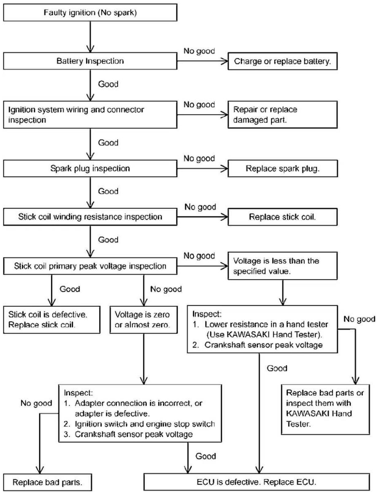
flowchart
graph TD
    A["Faulty ignition (No spark)"] --> B["Battery Inspection"]
    B -->|Good| C["Ignition system wiring and connector inspection"]
    B -->|No good| D["Charge or replace battery."]
    C -->|Good| E["Spark plug inspection"]
    C -->|No good| F["Repair or replace damaged part."]
    E -->|Good| G["Stick coil winding resistance inspection"]
    E -->|No good| H["Replace spark plug."]
    G -->|Good| I["Stick coil primary peak voltage inspection"]
    G -->|No good| J["Replace stick coil."]
    I -->|Good| K["Stick coil is defective. Replace stick coil."]
    I -->|No good| L["Voltage is zero or almost zero."]
    L --> M["Inspect: 1. Adapter connection is incorrect, or adapter is defective.<br>2. Ignition switch and engine stop switch<br>3. Crankshaft sensor peak voltage"]
    M --> N["Replace bad parts."]
    M --> O["ECU is defective. Replace ECU."]
    N --> P["Replace bad parts."]
    N --> Q["ECU is defective. Replace ECU."]
    L --> R["Inspect: 2. Crankshaft sensor peak voltage"]
    R --> S["Replace bad parts or inspect them with KAWASAKI Hand Tester."]
    S --> T["No good"]
    R --> U["Replace bad parts or inspect them with KAWASAKI Hand Tester."]
GP10280B F
IgnitionSystemCircuit
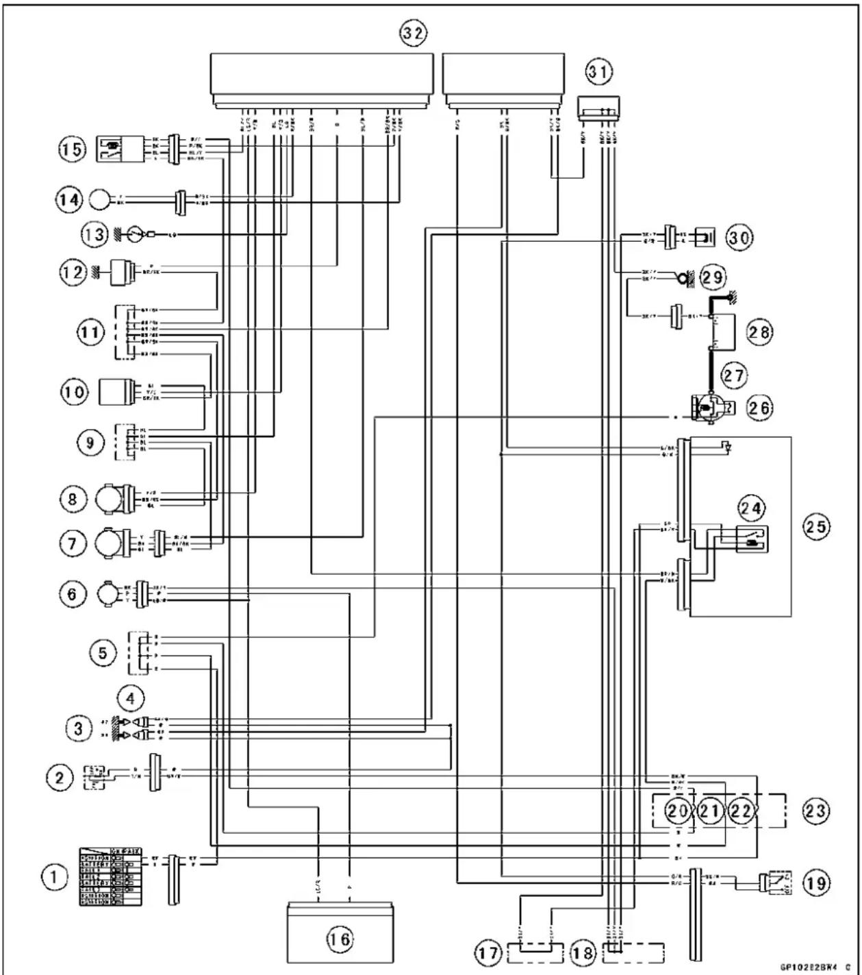
flowchart
graph TD
    A["1"] --> B["2"]
    B --> C["3"]
    C --> D["4"]
    D --> E["5"]
    E --> F["6"]
    F --> G["7"]
    G --> H["8"]
    H --> I["9"]
    I --> J["10"]
    J --> K["11"]
    K --> L["12"]
    L --> M["13"]
    M --> N["14"]
    N --> O["15"]
    O --> P["31"]
    P --> Q["32"]
    Q --> R["30"]
    R --> S["29"]
    S --> T["28"]
    T --> U["27"]
    U --> V["26"]
    V --> W["25"]
    W --> X["24"]
    X --> Y["23"]
    Y --> Z["22"]
    Z --> AA["21"]
    AA --> AB["20"]
    AB --> AC["19"]
    AC --> AD["18"]
    AD --> AE["17"]
    AE --> AF["16"]
    AF --> AG["15"]
-
IgnitionSwitch
-
EngineStopSwitch
3.SparkPlugs
4.StickCoils
- Water-proof JointC
6.SpeedSensor
7.SubthrottleSensor
8.MainThrottleSensor
-
Water-proof JointD
-
Vehicle-downSensor
-
Water-proof JointE
-
WaterTemperatureSensor
-
NeutralSwitch
14.CrankshaftSensor
15.OxygenSensor
16.MeterUnit
-
Water-proof JointA
-
Water-proofJointB
-
StarterLockoutSwitch
20.OxygenSensorHeaterFuse 10 A
21.ECUFuse15A
22.IgnitionFuse10A
23.FuseBox
24.ECUMainRelay
25.RelayBox
26.MainFuse30A
- StarterRelay
28.Battery12V10Ah
29.FrameGround
30.SidestandSwitch
31.JointConnector
32.ECU
ElectricStarterSystem
StarterMotorRemoval
CAUTION
Donottapthestartermotorshaftorbody.Tapping theshaftorbocoulddamagethemotor.
- Removethefueltank(seeFuelTankRemovalintheFuel System(DFI)chapter).
- Slidebacktherubbercap[A].
- Removethestartermotorcableterminalnut[B].
- Removethemountingbolts[A].
- Pulloutthestartermotor[B].


StarterMotorInstallation
CAUTION
Donottapthestartermotorshaftorbody.Tapping theshaftorbocoulldamagethemotor.
- Wheninstallingthestartermotor,cleanthestartermotorlegs[A]andcrankcase[B]wherethestartermotoris grounded.
- ReplacetheO-ring[A]withanewone.
- ApplygreasetotheO-ring.
- Applyanon-permanentlockingagenttothethreadsof theboltsandtightenthebolts.
Torque-StarterMotorMountingBolts:9.8N·m(1.0kgf·m, 87in·lb)
• Installthestartermotorcable.
- Tighten:
Torque-StarterMotorCableTerminalNut:6.0N·m(0.60 kgf·m,53in·lb)

natural_image
Close-up of a mechanical component with labeled parts A and B, showing assembly details (no readable text or symbols)
natural_image
Mechanical component with labeled section A, no visible text or symbols on the body itselfStarterMotorDisassembly
- Removethestartermotor(seeStarterMotorRemoval).
- Takeoffthestartermotorthroughbolts[A]andremove thebothendcovers[B]andpullthearmatureoutofthe yoke[C].

ElectricStarterSystem
- Remove:
TerminalLocknutandWashers
O-ring
- Removethebrushplateassy[A]fromtheyoke[B].
- Removethebrushplate[A]fromtheplatecover[B].
NOTE
○ Donotremovethenegativecarbonbrushesformthe brushplate.
StarterMotorAssembly
- Installthebrushplate[A]totheplatecover[B]asshown.
• Installthebrushplateassytotheyoke.
- Clampthesprings[A]withtheclips[B].
- Fitthearmature[C]tothebrushplateassy[D].
- Removetheclips.
• InstallthenewO-ring[A]asshown.
- Install:
Washers[B]andTerminalLocknut[C]
- Tighten:
Torque-StarterMotorTerminalLocknut:11N·m(1.1 kgf·m,97in·lb)

natural_image
Cross-sectional view of a mechanical device with labeled parts (A, B), no visible text or symbols beyond labels
natural_image
Close-up of a mechanical component with labeled parts A and B, no readable text or symbols beyond labels
natural_image
Close-up of a mechanical component with labeled parts A and B, no readable text or symbols beyond labels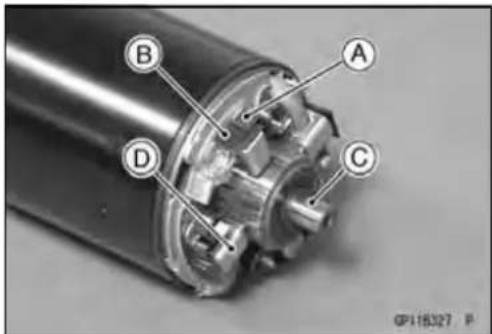

flowchart
graph TD
    A["Component A"] --> B["Component B"]
    B --> C["Component C"]
    B --> D["Component D"]
    B --> E["Component E"]
    B --> F["Component F"]
    B --> G["Component G"]
    style A fill:#f9f,stroke:#333
    style B fill:#ccf,stroke:#333
    style C fill:#cfc,stroke:#333
    style D fill:#fcc,stroke:#333
    style E fill:#cff,stroke:#333
    style F fill:#ffc,stroke:#333
    style G fill:#cfc,stroke:#333
ElectricStarterSystem
- Alignthelines[A]ontheyokewiththeendcoverlines[B].
● Tightenthethroughbolts.
Torque-StarterMotorThroughBolts:4.9N·m(0.50kgf·m, 43in·lb)
BrushInspection
● Measurethelengthofeachbrush[A].
★Ifanyisworndowntotheservicelimit,replacebrush plateassy[B]andtheterminalboltassy[C].
StarterMotorBrushLength
Standard:12mm(0.47in.)
ServiceLimit:6.0mm(0.24in.)
CommutatorCleaningandInspection
- Smooththecommutatorsurface[A]ifnecessarywithfine emerycloth[B],andcleanoutthegrooves.
- Measurethediameter[A]ofthecommutator[B].
★ If the commutator diameter is less than the service limit, replace the starter motor with anewone.
CommutatorDiameter
Standard:28mm(1.10in.)
ServiceLimit:27mm(1.06in.)
ArmatureInspection
- Usingthe×1Ω handtesterrange,measuretheresistancebetweenanytwocommutatorsegments[A].
SpecialTool-HandTester:57001-1394
★ If there is a high resistance on noreading ( ) between any two segments, awinding is open and the starter motor must bere placed.
- Using the highest hand test range, measure the resistance between these segments and the shaft [B].
★ If there is any reading at all, the immature has a short and the starter motorm must be replaced.


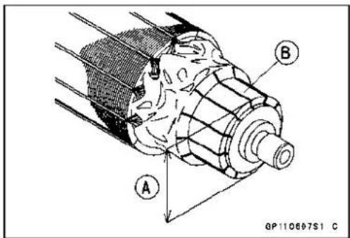

NOTE
Eveniftheforegoingchecksshowthearmaturetobe good, itmaybedefectiveinsomemannernotreadily detectablewiththehandtester. Ifallotherstartermotor andstartermotorcircuitcomponentscheckgood, but thestartermotorstilldoesnotturnoveroronlyturns overweakly, replacetheartermotorwithanewone.
BrushLeadInspection
- Usingthe×1Ω handtesterrange,measuretheresistanceasshown.
TerminalBoltandPositiveBrushes[A]
BrushPlateandNegativeBrushes[B]
SpecialTool-HandTester:57001-1394
★Ifthereisnotclosetozeroohms,thebrushleadhasan open.Replacetheterminalboltassyand/orthebrush plateassy.
BrushPlateandTerminalBoltInspection
- Using the highest and test range, measure the resistance as shown.
TerminalBoltandBrushPlate[A]
TerminalBoltandNegativeBrushHolders[B]
TerminalBoltandYoke[C]
SpecialTool-HandTester:57001-1394
★Ifthereisanyreading,thebrushplateassyand/orterminalboltassyhaveashort.Replacehebrushplateassy andtheterminalboltassy.
StarterRelayInspection
- Remove:
Bolt[A]andCover[B]
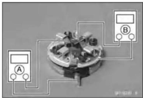
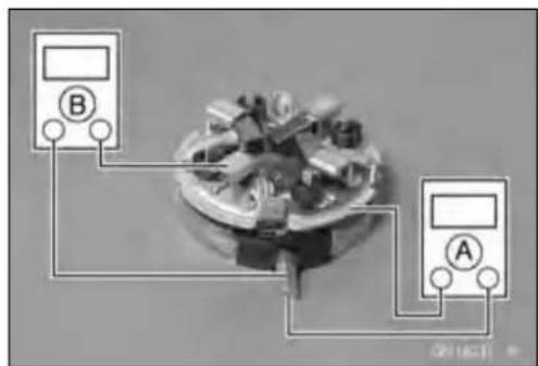
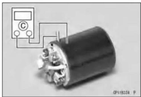
natural_image
Close-up of a cylindrical electronic component with a digital multimeter connected to its top terminal (no visible text or symbols)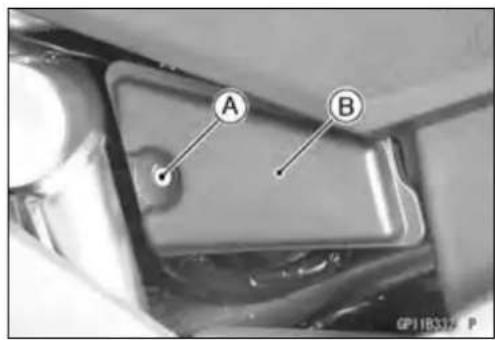
ElectricStarterSystem
- Disconnecttheconnector[A].
- Disconnectthestartermotorcable[B]andbatterypositive (+)cable[C]fromthestarterrelay[D].
CAUTION
Thebatterypositive(+)cablewiththerubbercapis connecteddirectlytothebatterypositive(+)terminalevenwhentheignitionswitchoff,sotakecare nottoshorttheremovedcabletochassisground.
- Connectthehandtester[A]and12Vbattery[B]tothe starterrelay[C]asshown.
SpecialTool-HandTester:57001-1394
★ Iftherelaydoesnotworkasspecified,therelayisdefective.Replacetherelay.
TestingRelay
TesterRange: ×1Ω range
Criteria: When battery is connected → 0Ω
When battery is disconnected → ∞ Ω


ElectricStarterCircuit

- IgnitionSwitch
- Water-proof JointB
- StarterLockoutSwitch
- IgnitionFuse10A
5.FuseBox
6.StarterCircuitRelay - RelayBox
8.StarterMotor - StarterRelay
10.MainFuse30A
11.Battery12V10Ah
12.SidestandSwitch
13.FrameGround
14.JointConnector - NeutralSwitch
16.Water-proofJointC
17.StarterButton - EngineStopSwitch
LightingSystem
Thismotorcycleadoptthedaylightsystemandhavea headlightrelayintherelaybox. Theheadlightdoesnot goonwhentheignitionswitchandtheenginestopswitch arefirstturnedon. Theheadlightcomesonafterthestarter buttonisreleasedandstaysonuntiltheignitionswitchis turnedoff. Theheadlightwillgooutmomentarilywhenever thestarterbuttonispressedandcomebackonwhenthe buttonisreleased.
HeadlightBeamHorizontalAdjustment
- RefertotheHeadlightAimingInspectioninthePeriodic Maintenancechapter.
HeadlightBeam Vertical Adjustment
- RefertotheHeadlightAimingInspectioninthePeriodic Maintenancechapter.
HeadlightBulbReplacement
- Remove: HeadlightAssy(seeHeadlightRemoval/Installation) HeadlightBulbDustCover[A]
- Remove: Hook[A] HeadlightBulb[B]
CAUTION
Whenhandlingthequartz-halogenbulb,never touchtheglassportionwithbarehands.Always useacleancloth.Oilcontaminationfromhandsor dirtyragscanreducebulblifeorcausethebulbto explode.
NOTE
○Cleanoffanycontaminationthatinadvertentlygetson thebulbwithalcoholorsoapandwatersolution.
- Replacetheheadlightbulb.
- Fittheprojection[A]ofthebulbinthehollow[B]oftheheadlight.
- Installthehook[C].

natural_image
Close-up of a mechanical component with textured surface and labeled point A (no readable text or symbols)

LightingSystem
- Fitthedustcover[A]withthe"Top"markupwardontothe bulb[B]firmlyasshown.
Good[C]
Bad[D]
TopMark[E]
- Afterinstallation, adjusttheheadlightaim(seeHeadlight AimingInspectioninthePeriodicMaintenancechapter).


natural_image
Close-up of a mechanical component with no visible text or symbolsCityLightBulbReplacement
- Removetheheadlightassy(seeHeadlightRemoval/Installation).
- Pulloutthesocket[A]togetherwiththebulb.
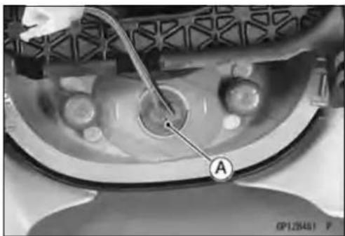
natural_image
Close-up medical image of a mechanical device with labeled component A (no readable text or symbols)- Pullthebulb[A]outofthesocket.
CAUTION
Donotturnthebulb.Pullthebulbouttoprevent damagetothebulb.Donotusebulbratedfor greaterwattagethenthespecifiedvalve.
- Replacethebulbwithanewone.

LightingSystem
HeadlightRemoval/Installation
- Remove: MountingBolts[A]

natural_image
Close-up of a mechanical component with a dial indicator and label 'A' (no readable text or symbols beyond the label)
- Disconnecttheheadlightconnectors[A]andcitylightconnector[B].
- Removetheheadlightassy.
- Removetheupperfairings(seeUpperFairingRemoval intheFramechapter).
- Installationisthereverseofremoval.


Tail/BrakeLightRemoval
- Remove:
SeatCovers(seeSeatCoverRemovalintheFrame chapter) - Disconnecttheconnector[A].
- Unscrewthemountingbolts[B].
- Removethetail/brakelight[C].
Tail/BrakeLightInstallation
- Installationisthereverseofremoval.
LightingSystem
LicensePlateLightBulbReplacement
- Remove:
Screws[A]
LicensePlateLightCover[B]
- Pushandturnthebulbcounterclockwiseandremoveit.
- Insertthenewbulb[A]byaligningitsupperandlowerpins[B]withtheupperandlowergrooves[C]inthesocket,and turnthebulbclockwise.
○Turnthebulbabout15°.
• Installthelicenseplatelightcover.
- Tighten:
Torque-LicensePlateLightCoverScrews:0.90N·m (0.090kgf·m,8in·lb)


LightingSystem
Headlight/TailLightCircuit
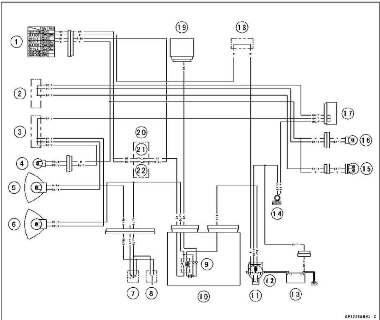
flowchart
graph TD
    A["①"] --> B["②"]
    B --> C["③"]
    C --> D["④"]
    D --> E["⑤"]
    E --> F["⑥"]
    F --> G["⑦"]
    G --> H["⑧"]
    H --> I["⑨"]
    I --> J["⑩"]
    J --> K["⑪"]
    K --> L["⑫"]
    L --> M["⑬"]
    M --> N["⑭"]
    N --> O["⑮"]
    O --> P["⑯"]
    P --> Q["⑰"]
    Q --> R["⑱"]
    R --> S["⑲"]
    S --> T["⑳"]
    T --> U["㉑"]
    U --> V["㉒"]
    V --> W["㉓"]
    W --> X["㉔"]
    X --> Y["㉕"]
    Y --> Z["㉖"]
    Z --> AA["㉗"]
    AA --> AB["㉘"]
    AB --> AC["㉙"]
    AC --> AD["㉚"]
    AD --> AE["㉛"]
    AE --> AF["㉜"]
    AF --> AG["㉝"]
    AG --> AH["㉟"]
    AH --> AI["㉟A"]
    AI --> AJ["㉟B"]
    AJ --> AK["㉟C"]
    AK --> AL["㉟D"]
    AL --> AM["㉟E"]
    AM --> AN["㉟F"]
    AN --> AO["㉟G"]
    AO --> AP["㉟H"]
    AP --> AQ["㉟I"]
    AQ --> AR["㉟J"]
    AR --> AS["㉟K"]
    AS --> AT["㉟L"]
    AT --> AU["㉟M"]
    AU --> AV["㉟N"]
    AV --> AW["㉟O"]
    AW --> AX["㉟P"]
    AX --> AY["㉟Q"]
- IgnitionSwitch
- Water-proofJointA
- Water-proofJointB
4.PositionLight
5.Headlight(HighBeam)
6.Headlight(LowBeam)
7.DimmerSwitch
8.PassingSwitch
9.HeadlightRelay
10.RelayBox
11.StarterRelay
TurnSignalLightBulbReplacement
- Unscrewthescrew[A]andremovethelens[B].
12.MainFuse30A
13.Battery12V10Ah
14.FrameGround
15. Tail/BrakeLight
16. LicensePlateLight12V5W
17.JointConnector
18. Water-proof JointC
19. Regulator/Rectifier
20.FuseBox
21.HeadlightFuse10A
22.TailLightFuse10A

LightingSystem
- Pushandturnthebulb[A]counterclockwiseandremove it.
- Insertthenewbulb[A]byaligningitsupperandlowerpins [B]withtheupperandlowergrooves[C]inthesocket,and turnthebulbclockwise.
○Turnthebulbabout15°.
- Install the projection of theelenstothedintsoftheturn signallight.
TurnSignalRelayInspection
- Remove: LeftCenterFairing(seeCenterFairingRemovalinthe Framechapter) TurnSignalRelay[A]
- Connectone12Vbatteryandturnsignallightsasindicatedinthefigure,andcounthowmaytimesthelights flashforoneminute.
TurnSignalRelay[A]
TurnSignalLights[B]
12VBattery[C]
★Ifthelightsdonotflashasspecified, replacetheturnsignalrelay.
TestingTurnSignalRelay
| Load | FlashingTimes (c/m*) | |
| TheNumberofTurn SignalLights | Wattage(W) | |
| 1** | 21or23140~250 | |
| 2 | 42 or 46 | 75 ~ 95 |
(*):Cycle(s)perminute
(**):Correctedto"onelightburnedout".

natural_image
Close-up of a mechanical component with a labeled section A pointing to a spherical object (no text or symbols beyond label)
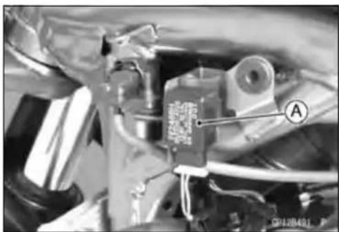
natural_image
Close-up of a mechanical assembly with labeled component A (no readable text or symbols)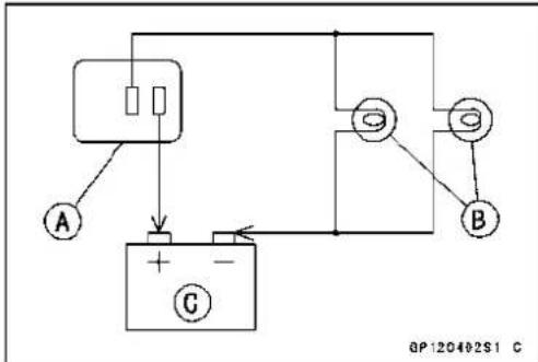
LightingSystem
TurnSignalLightCircuit

flowchart
graph TD
    A["①"] --> B["②"]
    B --> C["③"]
    C --> D["④"]
    D --> E["⑤"]
    E --> F["⑥"]
    F --> G["⑦"]
    G --> H["⑧"]
    H --> I["⑨"]
    I --> J["⑩"]
    J --> K["⑪"]
    K --> L["⑫"]
    L --> M["⑬"]
    M --> N["⑭"]
    N --> O["⑮"]
    O --> P["⑯"]
    P --> Q["⑰"]
    Q --> R["⑱"]
    R --> S["⑲"]
    S --> T["⑳"]
    T --> U["㉑"]
    U --> V["㉒"]
    V --> W["㉓"]
    W --> X["㉔"]
    X --> Y["㉕"]
    Y --> Z["㉖"]
    Z --> AA["㉗"]
    AA --> AB["㉘"]
    AB --> AC["㉙"]
    AC --> AD["㉚"]
    AD --> AE["㉛"]
    AE --> AF["㉜"]
    AF --> AG["㉝"]
    AG --> AH["㉟"]
    AH --> AI["㉟c"]
    AI --> AJ["㉞"]
    AJ --> AK["㉟d"]
    AK --> AL["㉟e"]
    AL --> AM["㉟f"]
    AM --> AN["㉟g"]
    AN --> AO["㉟h"]
    AO --> AP["㉟i"]
    AP --> AQ["㉟j"]
    AQ --> AR["㉟k"]
    AR --> AS["㉟l"]
    AS --> AT["㉟m"]
    AT --> AU["㉟n"]
    AU --> AV["㉟o"]
    AV --> AW["㉟p"]
    AW --> AX["㉟q"]
    AX --> AY["㉟r"]
    AY --> AZ["㉟t"]
    AZ --> BA["㉟u"]
    BA --> BB["㉟v"]
    BB --> BC["㉟w"]
    BC --> BD["㉟x"]
    BD --> BE["㉟y"]
    BE --> BF["㉟z"]
1.MeterUnit
2. Water-proof JointA
3. Water-proofJointB
4.FrontRightTurnSignalLight
5.FrontLeftTurnSignalLight
6. TurnSignalRelay
7.HazardButton
8. TurnSignalSwitch
9.FuseBox
10.TurnSignalRelayFuse10A
11.MainFuse30A
12.Battery12V10Ah
13.FrameGround
14. RearRightTurnSignalLight
15.RearLeftTurnSignalLight
16.JointConnector
17.Water-proofJointC
18.IgnitionSwitch
19.FrameGround
AirSwitchingValve
AirSwitching ValveOperationTest
- Removethefueltank(seeFuelTankRemovalintheFuel System(DFI)chapter).
-
Pulltheairswitchingvalvehose[A]outoftheaircleaner base.
-
Taketheairswitchingvalvehoseendoutsideofthe frame.
- Reinstallthefueltank(seeFuelTankInstallationinthe FuelSystem(DFI)chapter).
- Starttheengineandrunitatidlespeed.
- Plug[A]theairswitchingvalvehose[B]endwithyour fingerandfeelvacuumpulsinginthehose.
★Ifthereisnovacuumpulsation,checkthehoselinefor leak.Ifthereisnoleak,checktheairswitchingvalve(see AirSwitchingValveUnitTest). - Applyasoapandwatersolutionorrubberlubricanttothe endoftheairswitchinghoseandinstallthehoseonthe fitting.
AirSwitchingValveUnitTest
- Removetheairswitchingvalve(seeAirSwitchingValveRemovalintheEngineTopEndchapter).
- Setthehandtester[A]tothe×Ω rangeandconnectitto theairswitchingvalveterminalsasshown.
SpecialTool-HandTester:57001-1394
AirSwitchingValveResistance
Standard: 18 \~ 22 Ω at 20°C (68°F)
★Iftheresistancereadingisexceptthespecifiedvalue,replaceitwithanewone.
- Connectthe12Vbattery[A]totheairswitchingvalve terminalsasshown.
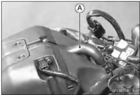
natural_image
Close-up of a mechanical component with labeled parts (A and CP108704), no readable text or symbols beyond labels


AirSwitchingValve
- Blowtheairtotheinletairduct[A], and makesuredoes notflowtheblownairfromtheoutletairduct[B].
- Disconnectthe12Vbattery.
- Blowtheairtotheinletairduct[A], and makesuredoes not flow the blownair from the outlet air duct[B].
★ If the air switching valued does not operate as described, replace it with anewone.
NOTE
○ Tocheckairflowthroughtheairswitchingvalve, just blowthroughtheaircleanerhose[C].


RadiatorFanSystem
FanMotorInspection
- Disconnecttheconnector[A].
- Usinganauxiliaryleads, supplybatterypowertothefan motor.
★Ifthefandoesnotrotate, thefanmotorisdefective and mustbereplaced.
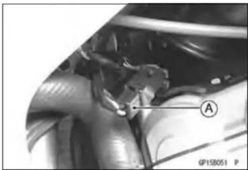
natural_image
Close-up of a mechanical component with labeled point A (no readable text or symbols beyond label)RadiatorFanCircuit

flowchart
graph TD
    A["1"] --> B["2"]
    B --> C["3"]
    C --> D["4"]
    D --> E["5"]
    E --> F["6"]
    F --> G["7"]
    G --> H["8"]
    H --> I["9"]
    I --> J["10"]
    J --> K["11"]
    K --> L["12"]
    L --> M["13"]
    M --> N["14"]
    N --> O["15"]
    O --> P["16"]
    style A fill:#f9f,stroke:#333
    style K fill:#f9f,stroke:#333
    style L fill:#f9f,stroke:#333
    style M fill:#f9f,stroke:#333
    style N fill:#f9f,stroke:#333
    style O fill:#f9f,stroke:#333
    style P fill:#f9f,stroke:#333
    style Q fill:#f9f,stroke:#333
    style R fill:#f9f,stroke:#333
    style S fill:#f9f,stroke:#333
    style T fill:#f9f,stroke:#333
    style U fill:#f9f,stroke:#333
    style V fill:#f9f,stroke:#333
    style W fill:#f9f,stroke:#333
    style X fill:#f9f,stroke:#333
    style Y fill:#f9f,stroke:#333
    style Z fill:#f9f,stroke:#333
    style AA fill:#f9f,stroke:#333
    style AB fill:#f9f,stroke:#333
    style AC fill:#f9f,stroke:#333
    style AD fill:#f9f,stroke:#333
    style AE fill:#f9f,stroke:#333
    style AF fill:#f9f,stroke:#333
    style AG fill:#f9f,stroke:#333
    style AH fill:#f9f,stroke:#333
    style AI fill:#f9f,stroke:#333
    style AJ fill:#f9f,stroke:#333
    style AK fill:#f9f,stroke:#333
    style AL fill:#f9f,stroke:#333
    style AM fill:#f9f,stroke:#333
    style AN fill:#f9f,stroke:#333
    style AO fill:#f9f,stroke:#333
    style AP fill:#f9f,stroke:#333
    style AQ fill:#f9f,stroke:#333
    style AR fill:#f9f,stroke:#333
    style AS fill:#f9f,stroke:#333
    style AT fill:#f9f,stroke:#333
    style AU fill:#f9f,stroke:#333
    style AV fill:#f9f,stroke:#333
    style AW fill:#f9f,stroke:#333
-
RelayBox
-
RadiatorFanRelay
3.ECUMainRelay
4.FuseBox
5.FanFuse15A
6.ECUFuse15A
7.MainFuse30A
8.Battery12V10Ah
9.FrameGround
10.JointConnector
11.ECU
- WaterTemperatureSensor
13.Water-proofJointE
14.Water-proofJointC
15.RadiatorFan
-
IgnitionSwitch
-
Water-proof JointA
-
Water-proof JointB
Meter, Gauge, Indicator Unit
MeterUnitRemoval
- Remove:
HeadlightAssy(seeHeadlightRemoval/Installation) Screws[A]andCover[B]
- Slidethedustcover[A]andremovetheconnector[B].
- Removethemeterunitbytakingoffthemountingscrews [C]withthewashers.
CAUTION
Placethemeterunitsothatthefaceisup.Ifameter unitisleftupsidedownorsidewaysforanylength oftime,itwillmalfunction.
Meter, GaugeDisassembly
- Remove:
MeterUnit(seeMeterUnitRemoval) Screws[A] LowerMeterCover[B]
- Separatethemeterassembly[A]anduppermetercover [B].

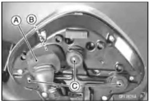
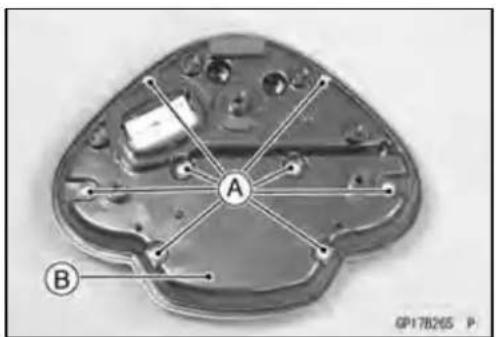

Meter, Gauge, Indicator Unit
ElectronicCombinationMeterUnitInspection
- RemovethemeterunitA.
[1]Battery(+)
[2]Ignition
[3]Ground(-)
[4]Unused
[5]SpeedSensorSignal
[6]TachometerSignal
[7]WaterTemperatureSensor(−)
[8]OilPressureWarningIndicatorLight(LED)(−)
[9]FuelLevelWarningIndicatorLight(LED)(−)
[10]SpeedSensorSupplyVoltage
[11]HighBeamIndicatorLight(LED)(+)
[12]NeutralIndicatorLight(LED)(−)
[13]Unused
[14]RightTurnSignalIndicatorLight(LED)(+)
[15]LeftTurnSignalIndicatorLight(LED)(+)
[16]FllIndicatorLight(LED)(−)
CAUTION
Donotdrophemeterunit.Placethemeterunitso thatitfacesupward.Ifthemeterunitisleftupside downorsidewaysforalongtimeordropped,itwill malfunction.Donotshorteachterminals.
LiquidCrystalDisplay(LCD)SegmentsCheck
- Usingtheauxiliarywires,connectthe12Vbatterytothe meterunitconnectorasfollows.
○Connectthebatterypositiveterminaltotheterminal[1].
○Connectthebatterynegativeterminaltotheterminal[3].
- Connecttheterminal[2]totheterminal[1].

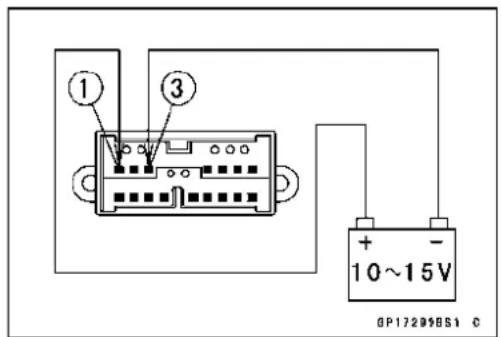

Meter, Gauge, Indicator Unit
○Whentheterminalsareconnected, alltheLCDsegments [A]andLEDwarninglights[B]appear(Flwarninglight appearfortwoseconds).
★ IftheLCDsegmentsandLEDwarninglightswillnotappear, replacethemeterassembly.
- Disconnecttheterminal[2].
○AlltheLCDsegmentsandLEDwarninglightdisappear.
★ If these segments donot disappear, replacethemeteras-sembly.
MODEANDRESETBUTTONOperationCheck
- Connectthe12Vbatteryandterminalsinthesamemannerasspecifiedinthe"LiquidCrystalDisplay(LCD)SegmentsCheck".
- CheckthatthedisplaychangetotheCLOCK,ODO,TRIP AandTRIPBdisplayseachtimetheMODEbutton[A]is pressed.
Olfthefuellevelgaugeflashed, displaychangetoCLOCK, ODO, TRIPA, TRIPBandFUEL.
★ Ifthedisplayfunctiondoesnotwork, replacethemeter assembly.


flowchart
graph TD
    A["CLOCK"] --> B["1:23"]
    B --> C["8756 ODO"]
    C --> D["TRIPA"]
    D --> E["23.5"]
    E --> F["TRIP B"]
    F --> G["138"]
    G --> H["FUEL"]
    H --> I["GP17298B52 C"]
- Indicatetheclockmode.
- Check that when the RESET button in CLOCK mode is pushed from more than two seconds, the meter display turnstotheclockset mode.
○Boththehourandminutedisplaystartflashing.

Meter, Gauge, Indicator Unit
- IntheHOUR/MINUTEsettingmode, press the RESET button again to effect the HOUR setting mode.
○Thehourdisplayflashesonthedisplay. -
PresstheMODEbuttontosetthehour.
-
IntheHOURsettingmode, presstheRESETbuttonto effecttheMINUTEsettingmode.
○Theminutedisplayflashesonthedisplay. -
PresstheMODEbuttontosetheminute.
-
IntheMINUTEsettingmode, presstheRESETbuttonto returntotheHOUR/MINUTEsettingmode.
- PresstheMODEbuttontocompletethetimesetting process.
○Theclockstartscountingthesecondsassoonasthe MODEbuttonispressed.
- IndicatetheODOmode.
- Checkthatthedisplay[A]changetothemileandkmdisplayeachtimebypushingtheRESETbuttonwhileMODE buttonpushedin.
NOTE
○ Mile/KmdisplaycanalternatebetweenEnglishand metricmodes(mileandkm)inthedigitalmeter.Make surethatkmormileaccordingtolocalregulationsis correctlydisplayedbeforeriding.
★ Ifthedisplayfunctiondoesnotworkandadjust,replace themeterassembly.
SpeedometerCheck
- Connectthe12Vbatteryandterminalsinthesamemannerasspecifiedinthe"LiquidCrystalDisplay(LCD)SegmentsCheck".
- Thespeedequivalenttotheinputfrequencyisindicatedin theoscillator[A],ifthesquarewave(illustratedasshown) wouldbeinputintotheterminal[5].
○Indicatesapproximately60mphincasetheinputfrequencywouldbeapproximately169.0Hz.
○Indicatesapproximately60km/hincasetheinputfrequencywouldbeapproximately105.6Hz.

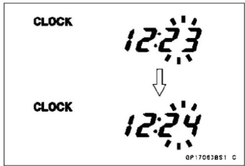
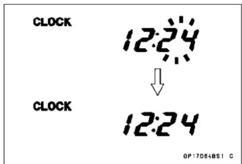


Meter, Gauge, Indicator Unit
- If the oscillator is not available, the speedometer can be checked as follows.
○Installthemeterunit.
○Raisetherearwheeloffthegroundwithstand.
○Turnontheignitionswitch.
○Rotatetherearwheelbyhand.
○Checkthatthespeedometershowsthespeed.
★ If the speedometer does not work, check the speed sensor are electric source voltage and speed sensor.
★Theelectricsourcevoltageandspeedsensorarenormal, replacethemeterassembly.
SpeedSensorElectricSourceCheck
- Connectthe12Vbatteryandterminalsinthesamemannerasspecifiedinthe"LiquidCrystalDisplay(LCD)SegmentsCheck".
- SetthehandtestertotheDC25Vrangeandconnectit totheterminals[10]and[3].
★ If the voltage is less than 8V, replacethemeter assembly.
OdometerCheck
- Checktheodometerwiththespeedometerinthesame way.
★ Ifvalueindicatedintheodometerisnotadded,replace themeterassembly.
NOTE
○ Thedataismaintainedevenifthebatteryisdisconnected.
○ Whenthefigurescometo999999, theyarestopped and locked.
TripA/BMeterCheck
- CheckthetripAorBmeterswiththespeedometerinthe sameway.
★IfvalueindicatedinthetripA/Bmetersisnotadded,re-placethemeterassembly. - Check that when the RESET button is pushed more than two seconds, the configured display turnsto 0.0.
★ If the figured display does not indicate 0.0, replacethemeterassembly.
TachometerCheck
- Connectthe12Vbatteryandterminalsinthesamemannerasspecifiedinthe"LiquidCrystalDisplay(LCD)SegmentsCheck".
- Therevolutionsperminute(rpm)equivalenttotheinput frequencyisindicatedintheoscillator[A]ifthesquare wave(illustratedasshown)wouldbeinputintotheterminal[6].
○Indicatesapproximately6000rpmincasetheinputfrequencywouldbeapproximately200Hz.

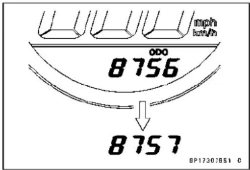


Meter, Gauge, Indicator Unit
- If the oscillator is not available, the tachometer can be checked as follows.
○Connectthe12Vbatteryandterminalsinthesamemannerasspecifiedinthe"LiquidCrystalDisplay(LCD)SegmentsCheck".
○Usinganauxiliarywire, quickopenandconnecttheter- minal[2]totheterminal[6]repeatedly.
○Thenthetachometerneedle[A]shouldflick[B].
★Iftheneedledoesnotflick, replacethemeterassembly.
IndicatorLightsInspection
- Connectthe12Vbatteryandterminalsinthesamemannerasspecifiedinthe"LiquidCrystalDisplay(LCD)Segmentscheck".
NeutralIndicatorLight(LED)[A]
FllIndicatorLight(LED)[B]
OilPressure/WaterTemperatureWarningIndicatorLight (LED)[C]
RightTurnSignalIndicatorLight(LED)[D]
LeftTurnSignalIndicatorLight(LED)[E]
HighBeamIndicatorLight(LED)[F]
FuelLevelWarningIndicatorLight(LED)[G]
- Usingtheauxiliaryleads,connecta12Vbatterytothe meterunitconnectorasfollows.
WaterTemperatureWarningIndicatorLight(LED)
BatteryNegative(−)TerminaltoTerminal[7]
OilPressureWarningIndicatorLight(LED)
BatteryNegative(−)TerminaltoTerminal[8]


Meter, Gauge, Indicator Unit
FuelLevelWarningIndicatorLight(LED)
BatteryNegative(−)TerminaltoTerminal[9]

HighBeamIndicatorLight(LED)
BatteryPositive(+)TerminaltoTerminal[11]
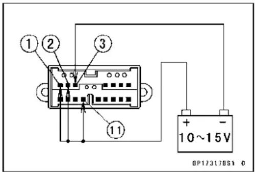
NeutralIndicatorLight(LED)
BatteryNegative(−)TerminaltoTerminal[12]

RightandLeftTurnSignalIndicatorLight(LED)
ForRightTurnSignalIndicatorLight(LED)
BatteryPositive(+)TerminaltoTerminal[14]
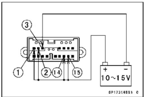
ForLeftTurnSignalIndicatorLight(LED)
BatteryPositive(+)TerminaltoTerminal[15]
FllIndicatorLight(LED)
BatteryNegative(−)TerminaltoTerminal[16]

- Ifeachlights(LED)doesnotgoon,replacethemeter assembly.
MeterCircuit
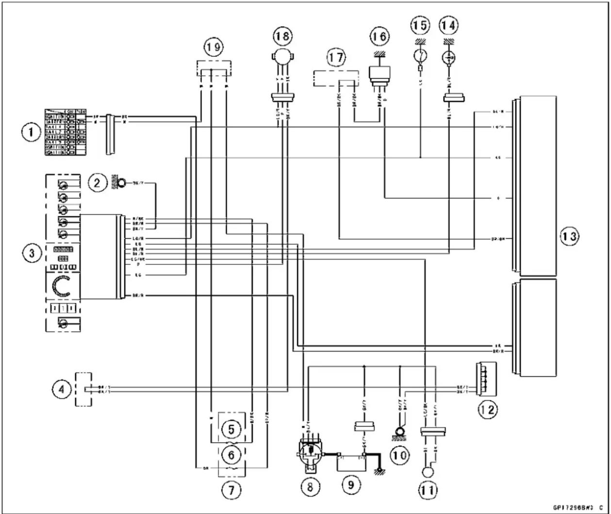
flowchart
graph TD
    A["Generator ①"] --> B["Resistors"]
    B --> C["Control Unit ③"]
    C --> D["Relays ②"]
    D --> E["Ground"]
    C --> F["Control Unit ④"]
    F --> G["Resistors"]
    G --> H["Control Unit ⑤"]
    H --> I["Relays ⑥"]
    I --> J["Control Unit ⑦"]
    J --> K["Output ⑧"]
    K --> L["Control Unit ⑩"]
    L --> M["Output ⑪"]
    M --> N["Control Unit ⑫"]
    N --> O["Output ⑬"]
    O --> P["Control Unit ⑭"]
    P --> Q["Output ⑮"]
    Q --> R["Control Unit ⑮"]
    R --> S["Output ⑯"]
    S --> T["Control Unit ⑰"]
    T --> U["Output ⑰"]
    U --> V["Control Unit ⑱"]
    V --> W["Output ⑱"]
    W --> X["Control Unit ⑲"]
    X --> Y["Output ⑲"]
    Y --> Z["Control Unit ⑳"]
    Z --> AA["Output ⑳"]
    AA --> AB["Control Unit ⑪"]
    AB --> AC["Output ⑪"]
    AC --> AD["Control Unit ⑫"]
    AD --> AE["Output ⑫"]
    AE --> AF["Control Unit ⑬"]
    AF --> AG["Output ⑬"]
    AG --> AH["Control Unit ⑭"]
    AH --> AI["Output ⑮"]
    AI --> AJ["Control Unit ⑮"]
    AJ --> AK["Output ⑮"]
    AK --> AL["Control Unit ⑯"]
    AL --> AM["Output ⑯"]
    AM --> AN["Control Unit ⑰"]
    AN --> AO["Output ⑰"]
    AO --> AP["Control Unit ⑱"]
    AP --> AQ["Output ⑱"]
    AQ --> AR["Control Unit ⑲"]
    AR --> AS["Output ⑲"]
    AS --> AT["Control Unit ⑳"]
    AT --> AU["Output ⑳"]
    AU --> AV["Control Unit ⑪"]
    AV --> AW["Output ⑪"]
- IgnitionSwitch
2.FrameGround
3.MeterUnit
- Water-proofJointB
5.ECUFuse15A
6.IgnitionFuse10A
7.FuseBox
8.MainFuse30A
9.Battery12V10Ah
10.FrameGround
11.FuelReserveSwitch
12.JointConnector
13.ECU
14.OilPressureSwitch
-
NeutralSwitch
-
Water Temperature Sensor
17.Water-proofJointE
18.SpeedSensor
19.Water-proofJointC
SwitchesandSensors
BrakeLightTimingInspection
- RefertotheBrakeLightSwitchOperationInspectionin thePeriodicMaintenancechapter.
BrakeLightTimingAdjustment
- RefertotheBrakeLightSwitchOperationInspectionin thePeriodicMaintenancechapter.
SwitchInspection
- Usingahandtester, checktoseethatonlytheconnectionsshowninthetablehavecontinuity(aboutzero ohms).
○Fortheswitchhousingsandtheignitionswitch,referto thetablesintheWiringDiagram.
★ Iftheswitchhasanopenorshort,repairitorreplaceit withanewone.
SpecialTool-HandTester:57001-1394
RearBrakeLightSwitchConnections
| Rear Brake Light Switch Connections | ||
| Color | BR | BL |
| When brake pedal is pushed down | ||
| When brake pedal is released | ||
SidestandSwitchConnections
| Sidestand Switch Connections | ||
| Color | BK | G |
| When sidestand is down | ||
| When sidestand is up | ○ | ○ |
NeutralSwitchConnections
| Neutral Switch Connections | ||
| Color | SW.Terminal | Ground |
| When transmission is in neutral | ||
| When transmission is not in neutral | ||
OilPressureSwitchConnections*
| Oil Pressure Switch Connections * | ||
| Color | SW.Terminal | Ground |
| When engine is stopped | ○ | ○ |
| When engine is running | ||
*:Enginelubricationsystemisingoodcondition.
SwitchesandSensors
WaterTemperatureSensorInspection
- Removethewatertemperaturesensor(seeRemoval/InstallationintheFuelSystem(DFI)chapter).
- Suspendthesensor[A]inacontainerofcoolantsothat thetemperature-sensingprojection[C]andthreadedportion[C]aresubmerged.
- Suspendanaccuratethermometer[B]withtemperature-sensingprojectionlocatedinalmostthesamedepth.
NOTE
○ Thesensorandthermometermustnottouchthecontainersideorbottom.
- Placethecontaineroverasourceofheatandgraduallyraisethetemperatureofthecoolantwhilestirringthe coolantgently.
- Usingthehandtester,measuretheinternalresistanceof thesensor.
★Ifthehandtesterdoesnotshowthespecifiedvalues,re-placethesensor.
WaterTemperatureSensorResistance
| Temperature | Resistance(kΩ) |
| -20°C(-4°F)*18.80±2.37 | |
| 0°C(32°F)*(about6.544) | |
| 40°C(104°F) | 1.136±0.095 |
| 100°C(212°F) | 0.1553±0.0070 |
*:ReferenceInformation
SpeedSensorRemoval
- Disconnectthespeedsensorleadconnector[A].
- Removetheenginesprocketcover(seeEngineSprocketRemovalintheFinalDrivechapter).
- Remove: Bolt[A] SpeedSensor[B]
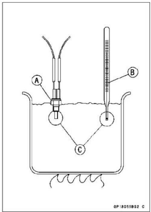

natural_image
Close-up mechanical assembly showing hoses, springs, and a labeled component (A), no readable text or symbols present.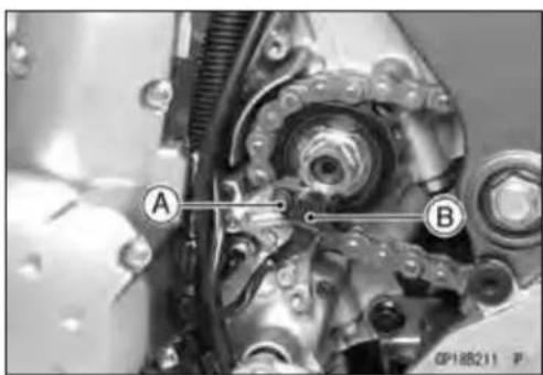
SpeedSensorInstallation
• Installationisthereverseofremoval.
- Applyanon-permanentlockingagenttothesensorbolt, andtightenit.
Torque-SpeedSensorBolt:7.8N·m(0.80kgf·m,69in·lb)
SwitchesandSensors
SpeedSensorInspection
- Removethespeedsensor(seeSpeedSensorRemoval).
- Connectthespeedsensorconnector[A]withthebattery [B],10kΩ resistor[C]andhandtester[D]asshown.
- SetthetestertotheDC25Vrange.
SpecialTool-HandTester:57001-1394

- Trace[A]eachsideofthespeedsensorsurfacewiththe screwdriver.
○Thenthetesterindicatorshouldflick[B].
★ Ifthetesterindicatordoesnotflick, replacethespeed sensor.

OxygenSensorRemoval(EuropeModels)
- Remove: LowerFairing(seeLowerFairingRemovalintheFrame chapter)
- Disconnecttheoxygenensorleadconnector[A].

natural_image
Close-up of mechanical components with labeled parts (A) and connectors, no readable text or symbols beyond labels- Removetheoxygen sensor[A].

natural_image
Close-up of a mechanical assembly with a labeled component (A) and bolted joint, no readable text or symbols present.OxygenSensorInstallation(EuropeModels)
CAUTION
Neverdroptheoxygen sensor[A],especiallyona hardsurface.Suchashocktotheunitcandamage it.Donottouchthesensingpart[B]andfilterholes [C]ofthesensortopreventoilcontact.Oilcontaminationfromhandscanreducesensorperformance.
- Tighten:
Torque-OxygenSensor:44.1N·m(4.50kgf·m,32.5ft·lb) - Runtheoxygen sensor lead correctly (see Cable, Wire, and Hose Routing section in the Appendix chapter).
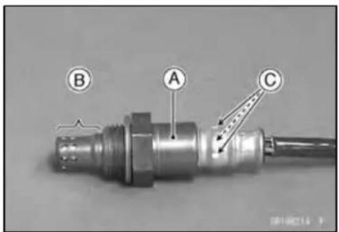
SwitchesandSensors
OxygenSensorInspection(EuropeModels)
- RefertotheOxygenSensorInspectionintheFuelSystem (DFI)chapter.
FuelReserveSwitchInspection
- Fillthefueltankwithfuel.
- Closethefueltankcapsurely.
- Removethefueltank(seeFuelTankRemovalintheFuel System(DFI)chapter).
- ConnectthetestlightAandthe12Vbattery[B]tothefuelpumpconnector [C].
Connections:
Battery(+)→ 12V3.4WBulb(OneSide)
12V3.4WBulb(OtherSide)→ BLLeadTerminal
Battery(-)→ BKLeadTerminal
★Ifthetestlightturnon,thereserveswitchisdefective. Replacethefuellevelsensor.
- Removethefuelpump(seeFuelPumpRemovalinthe FuelSystem(DFI)chapter).
- Connectthetestlight(12V3.4Wbulbinasocketwith leads)andthe12Vbatterytothefuelpumpconnectoras shown.
12VBattery[A]
TestLight[B]
FuelPumpConnector[C]
FuelReserveSwitch[D]
★Ifthetestlightdoesn'tlight,replacethefuelpump.

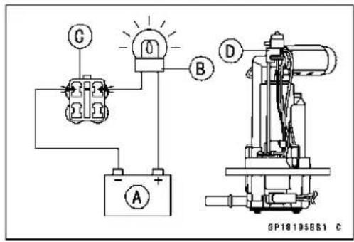
NOTE
Olt may take along timetoturnonthetestlightincase that the fuel reserves switch is inspected just after the fuel pump is removed. Leav the fuel reserves switch with leads for inspection connected for few minutes.
RelayBox
Therelaybox[A]hasrelaysanddiodes. Therelaysand diodescannotberemoved.
RelayBoxRemoval
- Remove:
FuelTank(seeFuelTankRemovalintheFuelSystem (DFI)chapter) - Takeouttherelaybox[A]anddisconnecttheconnectors [B].

natural_image
Close-up of a mechanical assembly with visible components and a labeled component (A), no readable text or symbols present.
RelayCircuitInspection
- Removetherelaybox(seeRelayBoxRemoval).
- Checkconductivityofthefollowingnumberedterminals byconnectingthehandtesterandone12Vbatterytothe relayboxasshown(seeRelayBoxInternalCircuitinthis section).
★ Ifthetesterdoesnotreadasspecified, replacetherelay box.
RelayCircuitInspection(withthebatterydisconnected)
RelayCircuitInspection(withthebatteryconnected)
| Battery Connection (+)(-) | Tester Connection | Tester Reading(Ω) | |||
| ECUMainRelay | 2-111-30 | ||||
| 4-57-60 | |||||
| FuelPumpRelay9-107-80 | |||||
| FanRelay18-1917-200 | |||||
| Battery Connection (+)(-) | TesterConnection DC25V Range | Tester Reading(V) | |||
| Starter CircuitRelay | 16-1211-12 | Battery Voltage | |||
(+):Apply positive lead.
(−): Apply negative lead.
Diode Circuit Inspection
- Remove the relay box (see Relay Box Removal).
- Check conductivity of the following pairs of terminals (see Relay Box Internal Circuit in this section).
DiodeCircuitInspection
| TesterConnection | 1-11,2-11,12-13,12-15,12-16,13-14,13-15 |
★The resistance should be low in one direction and more than ten times as much in the other direction. If any diode shows low or high in both directions, the diode is defective and the relay box must be replaced.
NOTE
○ The actual meter reading varies with the meter or tester used and the individual diodes, but generally speaking, the lower reading should be from zero to one half the scale.
RelayBox
RelayBoxInternalCircuit


GP19010B72 C
A:HeadlightRelay
B:ECUMainRelay
C:FuelPumpRelay
D:StarterCircuitRelay
E:FanRelay
Fuse
30AMainFuseRemoval
- Remove:
LeftSideCover(seeSideCoverRemovalintheFrame chapter) Cover(seeStarterRelayInspection) Connector[A]
- Pulloutthemainfuse[B]fromthestarterrelaywithneedle nosepliers.
FuseBoxFuseRemoval
- Removetheseat(seeSeatRemovalintheFramechapter).
- Unlockthehook[A]toliftupthelid[B].
- Pullthefuses[A]straightoutofthefuseboxwithneedle nosepliers.
15AECUFuseRemoval
- Remove:
Seat(seeSeatRemovalintheFramechapter)
- Unlockthehook[A]topullthelid[B].
- PullouttheECUfuse[A]fromthefusebox.


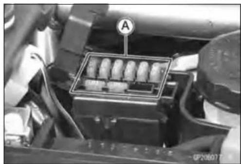
natural_image
Close-up of a vehicle engine compartment with a highlighted component labeled 'A' (no readable text or symbols beyond label)

Fuse
FuseInstallation
- Ifafusefailsduringoperation,inspecttheelectricalsystemtodeterminethecause,andthenreplaceitwithanewfuseofproperamperage.
- Installthefuseboxfusesontheoriginalpositionasspecifiedonthelid.
FuseInspection
- Removethefuse(see30AMain/FuseBox/15AECU FuseRemoval).
- Inspectthefuseelement.
★Ifitisblownout, replacethefuse. Before replacing a blownfuse, always check the amperage in the affected circuit. If the amperage is equal to greater than the fuserating, check the wiring and related components for ashort circuit.
Housing[A]
FuseElement[B]
Terminals[C]
BlownElement[D]

CAUTION
Whenreplacingafuse, besurethenewfuse matchesthespecifiedfuseratingforthatcircuit. Installationofafusewithahigherratingmaycause damagetowiringandcomponents.
Appendix
TableofContents
Cable, Wire, and Hose Routing.... 17-2
Troubleshooting Guide 17-26
17-2 APPENDIX
Cable, Wire, and HoseRouting

Cable, Wire, and HoseRouting
- Clamp (From the on sequentially, through the left switch housing lead, ignition switch lead and mainharness.)
2.LeftSwitchHousingLeadConnector - Clamp(Inserttheclampfromaircleanerside.)
- AirSwitching Valve Lead Connector
5.MainHarness - Clamp
- Clamp(Inserttheclampintheframe.)
- Clamp(Inserttheclampintheframe.)
- Clamp
10.InletTemperatureSensorLeadConnector - Clamp(Inserttheclampfromaircleanerside.)
- IgnitionSwitchLeadConnector
- Clamp(Clamptheleftswitchhousinglead(mainharnessside)andignitionswitchlead(mainharnessside).)
17-4APPENDIX
Cable, Wire, and HoseRouting
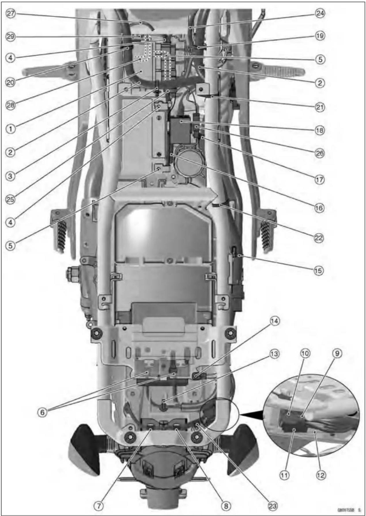
Cable, Wire, and HoseRouting
- RelayBox
2.MainHarness - Clamp(Inserttheclampinthebracket.)
4.BatteryNegativeCable
5.BatteryPositiveCable
6.ECUConnectors - Clamp
- Clamp
- TailLightConnector
- LicensePlateLightConnector
- RearLeftTurnSignalLightConnector
- RearRightTurnSignalLightConnector
- Clamp(Inserttheclampintherearfenderrear.)
14.FrameGround
15.Clamp
16.Water-proofJoint
17.Clamp
18.FuseBox
19.Clamp
20.Clamp
21.Band
22.Band
23.Clamp
24.TotheVehicle-downSensor,CrankshaftSensorandRearBrakeSwitch - Clamp (Clamp the regulator/rectifier lead and battery negative cable, and insert the clamp in the rearfenderfront.)
26.BatteryNegativeLeadConnector
27.FuelPumpLead
28.StarterMotorCable
29.ToStarterRelay

Cable, Wire, and HoseRouting
- InletPressureSensor
- TurnSignalRelay
- Clamp(Inserttheclampintheframe.)
4.HornLead - TotheWaterTemperatureSensor
6.OxygenSensorLeadConnector - Clamp(Throughthesidestandswitchleadandoxygensensorleadintheclamp.)
8.OxygenSensorLead - Clamp(Throughthedrainhoseintheclamp.)
10.DrainHose
11.SidestandSwitchLead
12.CorrugatedTube - Alternator Lead Connector
14.SidestandSwitchLeadConnector
15.SpeedSensorLeadConnector
16.MainThrottleSensorLeadConnector
17.Tube - NeutralSwitchLead
- Clamp(Inserttheclampintheenginebracket.)
- Clamp(Inserttheclampinthecrosspipe.)
21.DrainHose(Throughthedrainhosebetweenmainharnessandaircleaner.)
17-8APPENDIX
Cable, Wire, and HoseRouting
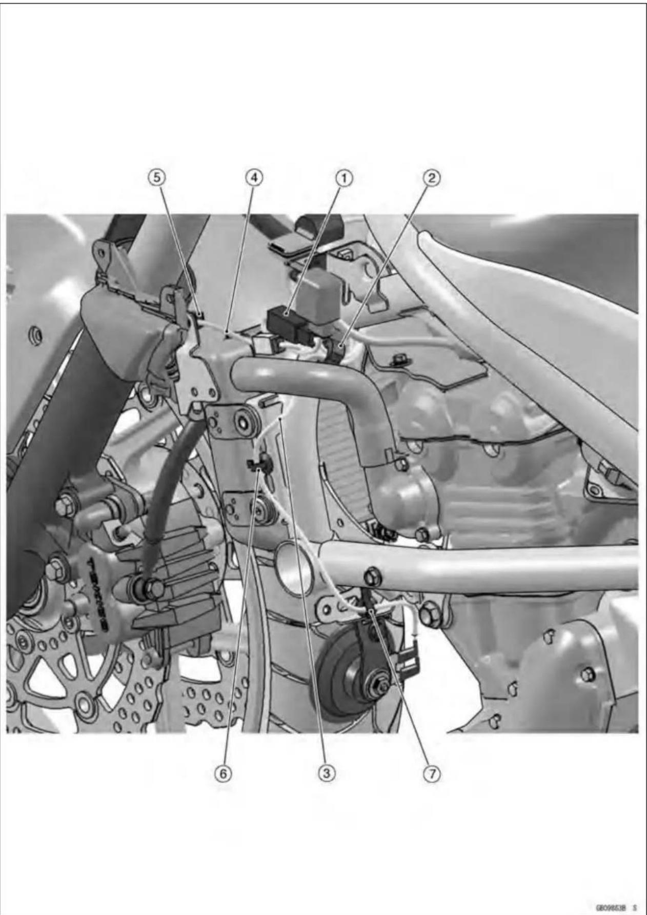
Cable, Wire, and HoseRouting
- RadiatorFanConnector
- Clamp(Throughthemainharnessandradiatorfanlead, and inserttheclampintheframe.)
- Through the horn lead between water pipe and frame.
- To Front Left Turn Signal Light
- Clamp(Inserttheclampinthebracket.)
- Clamp(Inserttheclampintheframe.)
- Clamp(Inserttheclampintheenginebracket.)
17-10APPENDIX
Cable, Wire, and HoseRouting

Cable, Wire, and HoseRouting
- Clamp(Throughtherightswitchhousinglead, and insert the clamp in the frame.)
- ClutchCable
3.ThrottleCables - Clamp
5.RightSwitchHousingLead - Clamp(Inserttheclampinthebracket.)
- Clamp(Inserttheclampintheframe.)
8.About45° - Clamp(Inserttheclampintheframe.)
10.CoolantHose
11.Clamp - Clamp(Throughtheclutchcableintheclamp.)
17-12APPENDIX
Cable, Wire, and HoseRouting

GEO9860B \$
Cable, Wire, and HoseRouting
- Crankshaft Sensor Lead Connector
- Clamp(Inserttheclampinthebracket.)
17-14APPENDIX
Cable, Wire, and HoseRouting

Cable, Wire, and HoseRouting
- TailLightConnector
- LicensePlateLightConnector
- RearRightTurnSignalLightConnector
- RearLeftTurnSignalLightConnector
- Clamp(Inserttheclampintherearfenderrear.)
- Clamp(Inserttheclampintherearfenderrear.)
7.DiagnosisConnector - Clamp(Inserttheclampintherearfenderfront.)
- RearBrakeLightSwitchLead
10.Band(Clampthemainharnesswiththeframe.)
11.Band

Cable, Wire, and HoseRouting
-
RightSwitchHousingLead
-
ThrottleCables
3.Headlight(LO)Connector
-
Headlight(HI) Connector
-
BrakeHose
-
Clamp
-
IgnitionSwitchLead
8.MainHarness
9.LeftSwitchHousingLead
10.ClutchCable
11.CityLightConnector
-
Clamp(Inserttheclampinthebracket.)
-
Clamp(Alightheclampwiththewhitetapeoftheharness.)
-
From the left sequentially, through the clutch cable, left switch housing lead, ignition switch lead and mainharness.
15.Clamp(Throughtheignitionswitchlead,andinserttheclampinthebracket.)
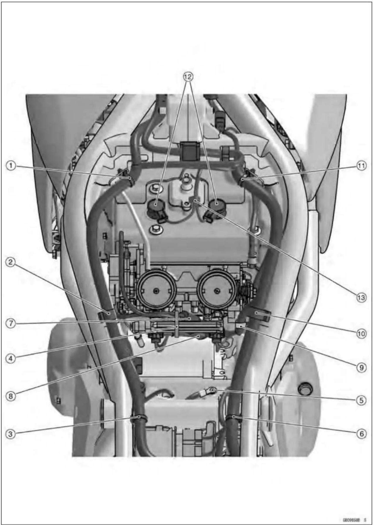
Cable, Wire, and HoseRouting
- Clamp
- Clamp
- Clamp
- Clamp (Clamp the main harness, subthrottle sensor lead and subthrottle valve actuator lead to thedeliverypipe.)
5.GroundLead - Clamp
7.SubthrottleSensorLeadConnector - Subthrottle Valve Actuator Lead Connector
- Clamp(Clamptheharness.)
10.Clamp
11.Clamp
12.StickCoilLeadConnector - Clamp(Clampthestickcoillead.)
17-20APPENDIX
Cable, Wire, and HoseRouting
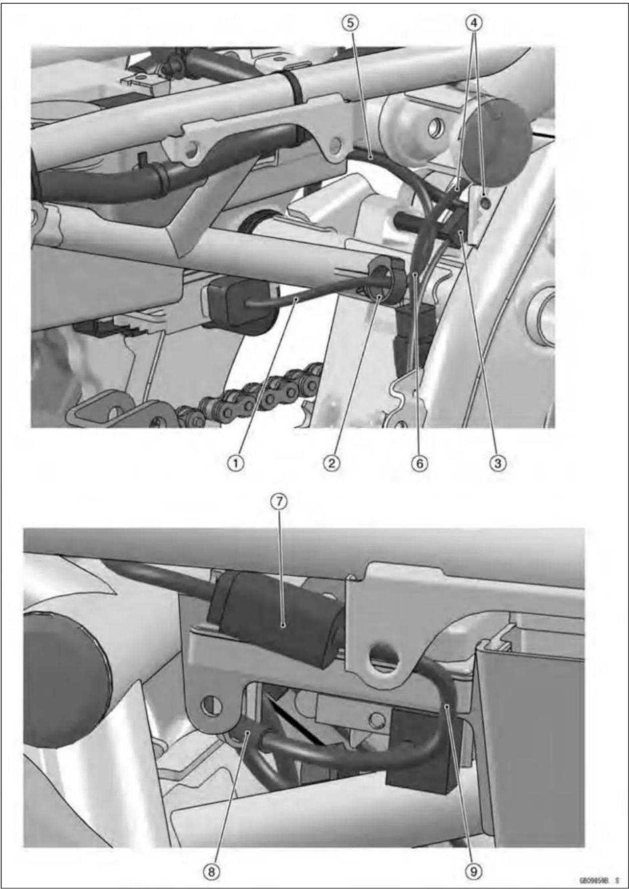
Cable, Wire, and HoseRouting
- Regulator/RectifierLead
- Clamp(Inserttheclampintheframe.)
- RearBrakeLightSwitchLeadConnector
- Through therearbrakelightswitchleadandvehicle-downsensorleadfromthefrontsideoftherarshockabsorberinstallationpart.
- Throughtheregulator/rectifierleadtothefrontopeningoftherearfenderfront.
- Vehicle-downSensorLead
7.FuelPumpLeadConnector - Through the fuelpumplead to the hook of there arfender front.
- Through the fuelpumplead to the slit of the cover.

Cable, Wire, and HoseRouting
- Clamp(Inserttheclampinthefrontfender.)
2.BrakeHose - Clamp
Cable, Wire, and HoseRouting

Cable, Wire, and HoseRouting
- BrakeHose
- Clamp
- Clamp
TroubleshootingGuide
NOTE
○ RefertotheFuelSystemchapterformost ofDFItroubleshootingguide.
○ Thisisnotanexhaustivelist, giving every possible cause foreach problem listed. It is meant simply as a rough guideto assist the troubleshooting for some of them more common difficulties.
EngineDoesn'tStart, Starting Difficulty:
Startermotornotrotating:
Starterlockoutswitchorneutralswitchtrouble
Startermotortrouble
Batteryvoltagelow
Starterrelaynotcontactingoroperating
Starterbuttonnotcontacting
Wiringopenorshorted
Ignitionswitchtrouble
Enginestopswitchtrouble
Fuseblown
Startermotorrotatingbutenginedoesn't
turnover:
Starterclutchtrouble
Vehicle-downsensor(DFI)comingoff
Transmissiongearorbearingseizure
Camshaftseizure
Starteridlegearseizure
Nofuelflow:
Nofuelintank
Fuelpumptrouble
Fueltankairventobstructed
Fuelfilterclogged
Fuellineclogged
Engineflooded:
Cleansparkplugandadjustpluggap
Startingtechniquefaulty
(When flooded, donotcrank the engine with the throttle fully opened. This promotes engine flood because more fuel supply is automatically by DFI.)
Nospark;sparkweak:
Vehicle-downsensor(DFI)comingoff IgnitionswitchnotON
EnginestopswitchturnedOFF
Clutchlevernotpulledinorgearnotinneutral
Batteryvoltagelow
Sparkplugdirty, broken, orgapmaladjusted
Stickcoilshortedornotingoodcontact
Stickcoiltrouble
Sparkplugincorrect
ICigniterinECUtrouble
Neutral, starterlockout, or sidestandswitch trouble
Crankshaftsensortrouble
Ignition switch or engine stop switch shorted
Wiringshortedoropen
Fuseblown
Fuel/airmixtureincorrect:
Bypassscrewand/oridleadjustingscrew maladjusted
Airpassageclogged
Aircleanerclogged,poorlysealed,ormissing
CompressionLow:
Sparkplugloose
Cylinder head not sufficiently tightened down
Novalveclearance
Cylinder, pistonworn
Piston ring bad (worn, weak, broken, or sticking)
Pistonring/grooveclearanceexcessive
Cylinderheadgasketdamaged
Cylinderheadwarped
Valve spring broken or weak
Valve not seating properly (valve bent, worn, orcarbonaccumulation on the seatingsurface)
PoorRunningatLowSpeed:
Sparkweak:
Batteryvoltagelow
Sparkplugdirty,broken,ormaladjusted
Stickcoilwiringtrouble
Stickcoilnotingoodcontact
Sparkplugincorrect
ICigniterinECUtrouble
Crankshaftsensortrouble
Stickcoiltrouble
Fuel/airmixtureincorrect:
Bypassscrewmaladjusted
Airpassageclogged
Airbleedpipebleedholesclogged
Pilotpassageclogged
Aircleanerclogged,poorlysealed,ormissing
Fueltankairventobstructed
Fuelpumptrouble
Throttlebodyassyholderloose
Aircleanerductloose
TroubleshootingGuide
Compressionlow:
Sparkplugloose
Cylinderheadnotsufficientlytightened down
Novalveclearance
Cylinder, pistonworn
Pistonringbad(worn,weak,broken,or sticking)
Pistonring/grooveclearanceexcessive
Cylinderheadwarped
Cylinderheadgasketdamaged
Valvespringbrokenorweak
Valvenotseatingproperly(valvebent, worn,orcarbonaccumulationonthe seatingsurface)
Other:
ICigniterinECUtrouble
Throttlebodyassynotsynchronizing
Engineoilviscositytoohigh
Drivetraintrouble
Brakedragging
Airsuctionvalvetrouble
Airswitchingvalvetrouble
Engineoverheating
Clutchslipping
PoorRunningorNoPoweratHigh
Speed:
Firingincorrect:
Sparkplugdirty,broken,ormaladjusted
Stickcoilwiringtrouble
Stickcoilnotingoodcontact
Sparkplugincorrect
Camshaftpositiontrouble
ICigniterinECUtrouble
Crankshaftsensortrouble
Stickcoiltrouble
Fuel/airmixtureincorrect:
Aircleanerclogged,poorlysealed,ormissing
AircleanerO-ringdamaged
Aircleanerductloose
Waterorforeignmatterinfuel
Throttlebodyassyholderloose
Fueltoinjectorinsufficient(DFI)
Fueltankairventobstructed
Fuellineclogged
Fuelpumptrouble
Compressionlow:
Sparkplugloose
Cylinderheadnotsufficientlytightened down
Novalveclearance
Cylinder, pistonworn
Pistonringbad(worn,weak,broken,or sticking)
Pistonring/grooveclearanceexcessive
Cylinderheadgasketdamaged
Cylinderheadwarped
Valvespringbrokenorweak
Valvenotseatingproperly(valvebent, worn,orcarbonaccumulationonthe seatingsurface)
Knocking:
Carbonbuiltupincombustionchamber
Fuelpoorqualityorincorrect
Sparkplugincorrect
ICigniterinECUtrouble
Crankshaftsensortrouble
Miscellaneous:
Throttlevalewon'tfullyopen
Brakedragging
Clutchslipping
Engineoverheating
Engineoilleveltoohigh
Engineoilviscositytoohigh
Drivetraintrouble
Airsuctionvalvetrouble
Airswitchingvalvetrouble
Catalytic converter melt down due to muffler overheating(KLEEN)
Overheating:
Firingincorrect:
Sparkplugdirty, broken, ormaladjusted
Sparkplugincorrect
ICigniterinECUtrouble
Muffleroverheating:
ForKLEEN, donotruntheengine even if with only one cylinder misfiring or poor running (Requestthenearestservicefacilitytocorrectit)
ForKLEEN, donotpush-startwithadead battery (Connect another full-charged battery with jumpercables, and start the engine using the electric starter)
ForKLEEN, donotstarttheengineunder misfireduetosparkplugfoulingorpoor connectionofthestickcoil
For KLEEN, do not coast the motorcycle withtheignitionswitchoff(TurntheignitionswitchONandruntheengine)
ICigniterinECUtrouble
Fuel/airmixtureincorrect:
Throttlebodyassyholderloose
Aircleanerductloose
Aircleanerpoorlysealed,ormissing
AircleanerO-ringdamaged
Aircleanerclogged
Compressionhigh:
Carbonbuiltupincombustionchamber
Engineloadfaulty:
Clutchslipping
Engineoilleveltoohigh
TroubleshootingGuide
Engineoilviscositytoohigh
Drivetraintrouble
Brakedragging
Lubricationinadequate:
Engineoilleveltoolow
Engineoilpoorqualityorincorrect
Gaugeincorrect:
Watertemperaturegaugebroken
Watertemperaturesensorbroken
Coolantincorrect:
Coolantleveltoolow
Coolantdeteriorated
Wrongcoolantmixedratio
Coolingsystemcomponentincorrect:
Radiatorfindamaged
Radiatorclogged
Thermostattrouble
Radiatorcaptrouble
Radiatorfanrelaytrouble
Fanmotorbroken
Fanbladedamaged
Waterpumpnotturning
Waterpumpimpellerdamaged
OverCooling:
Gaugeincorrect:
Watertemperaturegaugebroken
Watertemperaturesensorbroken
Coolingsystemcomponentincorrect:
Radiatorfanrelaytrouble
Thermostattrouble
ClutchOperationFaulty:
Clutchslipping:
Frictionplatewornorwarped
Steelplatewornorwarped
Clutchspringbrokenorweak
Clutchhuborhousingunevenlyworn
Noclutchleverplay
Clutchinnercabletrouble
Clutchreleasemechanismtrouble
Clutchnotdisengagingproperly:
Clutchplatewarpedortoorough
Clutchspringcompressionuneven
Engineoildeteriorated
Engineoilviscositytoohigh
Engineoilleveltoohigh
Clutchhousingfrozenondriveshaft
Clutchhubnutloose
Clutchhubsplinedamaged
Clutchfrictionplateinstalledwrong
Clutchleverplayexcessive
Clutchreleasemechanismtrouble
GearShiftingFaulty:
Doesn'tgointogear;shiftpedaldoesn't
return:
Clutchnotdisengaging
Shiftforkbentorseized
Gearstuckontheshaft
Gearpositioningleverbinding
Shiftreturnspringweakorbroken
Shiftreturnspringpinloose
Shiftmechanismarmspringbroken
Shiftmechanismarmbroken
Shiftpawlbroken
Jumpsoutofgear:
Shiftforkearworn,bent
Geargrooveworn
Geardogsand/ordogholesworn
Shiftdrumgrooveworn
Gearpositioningleverspringweakorbroken
Shiftforkguidepinworn
Driveshaft, outputshaft, and/orgear splinesworn
Overshifts:
Gearpositioningleverspringweakorbroken
Shiftmechanismarmspringbroken
AbnormalEngineNoise:
Knocking:
ICigniterinECUtrouble
Carbonbuiltupincombustionchamber
Fuelpoorqualityorincorrect
Sparkplugincorrect
Overheating
Pistonslap:
Cylinder/pistonclearanceexcessive
Cylinder, pistonworn
Connectingrodbent
Pistonpin,pistonpinholeworn
Valvenoise:
Valveclearanceincorrect
Valvespringbrokenorweak
Camshaftbearingworn
Valvelifterworn
Othernoise:
Connectingrodsmallendclearanceexcessive
Connectingrodbigendclearanceexcessive
Pistonring/grooveclearanceexcessive
Pistonringworn,broken,orstuck
Crankshaftrunoutexcessive
TroubleshootingGuide
Enginemountloose
Crankshaftbearingworn
Primarygearwornorchipped
Camshaftchaintensionertrouble
Camshaftchain, sprocket, guideworn
Airsuctionvalvedamaged
Airswitchingvalvedamaged
Alternatorrotorloose
Catalyticconvertermeltdownduetomuffler overheating(KLEEN)
AbnormalDriveTrainNoise:
Clutchnoise:
Clutchhousing/frictionplateclearanceexcessive
Clutchhousinggearworn
Wronginstallationofoutsidefrictionplate
Transmissionnoise:
Bearingsworn
Transmissiongearwornorchipped
Metalchipsjammedingearteeth
Engineoilinsufficient
Drivelinenoise:
Drivechainadjustedimproperly
Drivechainworn
Rearand/orenginesprocketworn
Chainlubricationinsufficient
Rearwheelmisaligned
AbnormalFrameNoise:
Frontforknoise:
Oilinsufficientortoothin
Springweakorbroken
Rearshockabsorbernoise:
Shockabsorberdamaged
Discbrakenoise:
Padinstalledincorrectly
Padsurfaceglazed
Discwarped
Calipertrouble
Othernoise:
Bracket, nut, bolt, etc. not properly mountedortightened
OilPressureWarningLightGoesOn:
Engineoilpumpdamaged
Engineoilscreenclogged
Engineoilfilterclogged
Engineoilleveltoolow
Engineoilviscositytoolow
Camshaftbearingworn
Crankshaftbearingworn
Oilpressureswitchdamaged
Wiringfaulty
Reliefvalvestuckopen
O-ringattheoilpassageinthecrankcase damaged
ExhaustSmokesExcessively:
Whitesmoke:
Pistonoilringworn
Cylinderworn
Valveoilsealdamaged
Valveguideworn
Engineoilleveltoohigh
Blacksmoke:
Aircleanerclogged
Brownsmoke:
Aircleanerductloose
AircleanerO-ringdamaged
Aircleanerpoorlysealedormissing
Handling and/or Stability Unsatisfactory:
Handlebarhardtoturn:
Cableroutingincorrect
Hoseroutingincorrect
Wiringroutingincorrect
Steeringstemnuttootight
Steeringstembearingdamaged
Steeringstembearinglubricationinadequate
Steeringstembent
Tireairpressuretoolow
Handlebarshakesorexcessivelyvibrates:
Tireworn
Swingarmpivotbearingworn
Rimwarped,ornotbalanced
Wheelbearingworn
Handlebarholderboltloose
Steeringstemnutloose
Front, rearaxlerunoutexcessive
Enginemountingboltloose
Handlebarpullstooneside:
Framebent
Wheelmisalignment
Swingarmbentortwisted
Swingarmpivotshaftrunoutexcessive
Steeringmaladjusted
Frontforkbent
Rightandleftfrontforkoilleveluneven
Shockabsorptionunsatisfactory:
(Toohard)
Frontforkoilexcessive
Frontforkoilviscositytoohigh
Rearshockabsorberadjustmenttoohard
Tireairpressuretoohigh
Frontforkbent
(Toosoft)
Tireairpressuretoolow
Frontforkoilinsufficientand/orleaking
Frontforkoilviscositytoolow
TroubleshootingGuide
Rearshockadjustmenttoosoft
Frontfork, rearshockabsorberspringweak
Rearshockabsorberoilleaking
BrakeDoesn'tHold:
Airinthebrakeline
Padordiscworn
Brakefluidleakage
Discwarped
Contaminatedpad
Brakefluiddeteriorated
Primaryorsecondarycupdamagedinmaster cylinder
Mastercylinderscratchedinside
BatteryTrouble:
Batterydischarged:
Chargeinsufficient
Batteryfaulty(toolowterminalvoltage)
Batteryleadmakingpoorcontact
Loadexcessive(e.g.,bulbofexcessive wattage)
Ignitionswitchtrouble
Alternatortrouble
Wiringfaulty
Regulator/rectifiertrouble
Batteryovercharged:
Alternatortrouble
Regulator/rectifiertrouble
Batteryfaulty
MODELAPPLICATION
| YearModel | BeginningFrameNo. | |
| 2006ER6 | 50A6F | JKAEREA1□6A000001ER650A-000001 |
| 2006ER6 | 50A6SJKAER650AAA | 000001 |
□: Thisdigitintheframenumberchangesfromonemachinetoanother.


- Motorcycle ServiceManual
- QuickReferenceGuide
- Foreword
- HowtoUseThisManual
- WARNING
- CAUTION
- NOTE
- GeneralInformation
- TableofContents
- 1-2GENERALINFORMATION
- BeforeServicing
- BatteryGround
- EdgesofParts
- Solvent
- Cleaning Vehicle before Disassembly
- ArrangementandCleaningofRemovedParts
- StorageofRemovedParts
- Inspection
- ReplacementParts
- AssemblyOrder
- TighteningSequence
- Tightening Torque
- Force
- Gasket, O-ring
- LiquidGasket, Non-permanentLockingAgent
- Press
- BallBearingandNeedleBearing
- OilSeal, GreaseSeal
- Circlips, CotterPins
- 1-6GENERALINFORMATION
- Lubrication
- DirectionofEngineRotation
- ElectricalWires
- Instrument
- ModelIdentification
- 1-10GENERALINFORMATION
- TechnicalInformation-CassetteTypeTransmission
- CassetteTypeTransmission
- 1-12GENERALINFORMATION
- TechnicalInformation-InletAirPressureSensor
- UnitConversionTable
- UnitsofTemperature:
- PeriodicMaintenance
- PeriodicMaintenanceChart
- 2-4 PERIODIC MAINTENANCE
- : Service more frequently when operating in severe conditions; dusty, wet, muddy, high speed or frequent starting/stopping.
- TorqueandLockingAgent
- 2-10 PERIODIC MAINTENANCE
- SpecialTools
- 2-14 PERIODIC MAINTENANCE
- PeriodicMaintenanceProcedures
- FuelSystem(DFI)
- IdleSpeedInspection
- IdleSpeedAdjustment
- 2-16PERIODICMAINTENANCE
- EngineVacuumSynchronizationInspection
- Donotremovetheinletairpressuresensorhose [B]ontheleftfittingofthethrottlebody.
- 2-18 PERIODIC MAINTENANCE
- Donotmeasuretheidlespeedbythetachometerof themeterunit.
- Donotovertightenthem. They could bedamaged, requiring replacement.
- CoolingSystem
- 2-20PERIODICMAINTENANCE
- AirSuctionSystem
- EngineTopEnd
- 1PistonTDCatEndofCompressionStroke→
- 2PistonTDCatEndofCompressionStroke→
- VALVECLEARANCEADJUSTMENTCHARTINLETVALVE
- VALVECLEARANCEADJUSTMENTCHARTEXHAUSTVALVE
- Clutch
- Wheels/Tires
- Wheel/TireDamageInspection
- TireTreadWear, AbnormalWearInspection
- TreadDepth
- WheelBearingDamageInspection
- DriveTrain
- 2-28PERIODICMAINTENANCE
- DriveChainSlackInspection
- ChainSlack
- DriveChainSlackAdjustment
- Misalignmentofthewheelwillresultinabnormal wearandmayresultinanunsaferidingcondition.
- Torque-RearAxleNut:108N·m(11.0kgf·m,80ft·lb)
- 2-30 PERIODIC MAINTENANCE
- DriveChainWearInspection
- ChainGuideInspection
- BrakeSystem
- 2-32PERIODICMAINTENANCE
- BrakeFluidLevelInspection
- RecommendedDiscBrakeFluid Grade:DOT4
- BrakePadWearInspection
- PadLiningThickness
- BrakeLightSwitchOperationInspection
- 2-34PERIODICMAINTENANCE
- Suspensions
- SteeringSystem
- 2-36PERIODICMAINTENANCE
- ElectricalSystem
- 2-38PERIODICMAINTENANCE
- LightsandSwitchesOperationInspection
- FirstStep
- SecondStep
- ThirdStep
- FourthStep
- 2-40PERIODICMAINTENANCE
- HeadlightAimingInspection
- HeadlightBeamHorizontalAdjustment
- HeadlightBeamVerticalAdjustment
- 2-42PERIODICMAINTENANCE
- EngineStopSwitchOperationInspection
- Others
- Pivots:LubricatewithGrease.
- Points:LubricatewithGrease.
- Cables:LubricatewithRustInhibitor.
- Bolt, Nutand Fastenertobechecked
- 2-46PERIODICMAINTENANCE
- OilFilterReplacement
- FuelHoseReplacement
- 2-48PERIODICMAINTENANCE
- 2-50PERIODICMAINTENANCE
- RadiatorHoseandO-ringReplacement
- 2-52PERIODICMAINTENANCE
- Torque-FrontBrakeReservoirCapScrews:1.0N·m(0.10 kgf·m,9in·lb)
- Torque-BleedValve:7.8N·m(0.80kgf·m,69in·lb)
- MasterCylinderRubberPartsReplacement
- FrontMasterCylinderDisassembly
- RearMasterCylinderDisassembly
- MasterCylinderAssembly
- 2-54PERIODICMAINTENANCE
- CaliperRubberPartsReplacement FrontCaliperDisassembly
- FrontCaliperAssembly
- RearCaliperDisassembly
- 2-56PERIODICMAINTENANCE
- RearCaliperAssembly
- SparkPlugReplacement
- DFISystem
- PartName
- TerminalNames
- DFIPartsLocation
- 3-16FUELSYSTEM(DFI)
- SpecialToolsandSealant
- DFIServicingPrecautions
- Outline
- TroubleshootingtheDFISystem
- DFIDiagnosisFlowChart
- InquiriestoRider
- DFISystemTroubleshootingGuide
- Self-Diagnosis
- Self-diagnosisOutline
- UserMode
- DealerMode1
- DealerMode2
- Self-diagnosis Procedures
- ServiceCodeClearingProcedures
- HowtoReadServiceCodes
- HowtoEraseServiceCodes
- ServiceCodeTable
- Notes:
- Backups
- Note:
- MainThrottleSensor(ServiceCode11)
- OutputVoltageInspection
- ResistanceInspection
- MainThrottleSensorCircuit
- InletAirPressureSensor(ServiceCode12)
- Removal
- Installation
- Input Voltage Inspection
- Output Voltage Inspection
- InletAirPressureSensorOutputVoltage ConnectionstoECU
- Suppose:
- InletAirPressureSensorCircuit
- Neverdropthesensor,especiallyonahardsurface. Suchashocktothesensorcandamageit.
- InletAirTemperatureSensor(ServiceCode13)
- SensorResistanceInspection
- InletAirTemperatureSensorCircuit
- WaterTemperatureSensor(ServiceCode14)
- WaterTemperatureSensorCircuit
- CrankshaftSensor(ServiceCode21)
- CrankshaftSensorRemoval/Installation
- CrankshaftSensorInspection
- CrankshaftSensorCircuit
- SpeedSensor(ServiceCode24,25)
- SpeedSensorRemoval/Installation
- SpeedSensorInspection
- SpeedSensorInputVoltageInspection
- SpeedSensorInputVoltage
- SpeedSensorOutputVoltageInspection
- 3-56FUELSYSTEM(DFI)
- SpeedSensorCircuit
- Vehicle-downSensor(ServiceCode31)
- Vehicle-downSensorOutputVoltage ConnectionstoSensor
- OutputVoltageatSensor
- Vehicle-downSensorCircuit
- SubthrottleSensor(ServiceCode32)
- 3-62FUELSYSTEM(DFI)
- SubthrottleSensorResistanceInspection
- ThrottleSensorResistance
- SubthrottleSensorCircuit
- OxygenSensor-notactivated(ServiceCode33)-EuropeModel
- OxygenSensorRemoval/Installation
- OxygenSensorInspection
- OxygenSensorOutputVoltage ConnectionstoOxygenSensorConnector
- OxygenSensorOutputVoltage(withPlugs)
- StickCoils(#1,#2:ServiceCode51,52)
- StickCoilRemoval/Installation
- StickCoilInputVoltageInspection
- Stick Coil Input Voltage at ECU Connections for Stick Coil #1
- InputVoltageatECU
- RadiatorFanRelay(ServiceCode56)
- RadiatorFanRelayRemoval/Installation
- RadiatorFanRelayInspection
- SubthrottleValveActuator(ServiceCode62)
- SubthrottleValveActuatorCircuit
- AirSwitching ValveRemoval/Installation
- AirSwitchingValveInspection
- OxygenSensorHeater(ServiceCode67)-EuropeModel
- OxygenSensorHeaterRemoval/Installation
- OxygenSensorHeaterInspection
- OxygenSensorResistance
- OxygenSensorPowerSourceVoltage
- Standard: BatteryVoltage
- OxygenSensor-IncorrectOutputVoltage(ServiceCode94)-EuropeModel
- OxygenSensorOutputVoltage(withoutPlugs)
- Standard: 0.2Vorless
- FllIndicatorLight(LED)
- InspectionFlowChart
- FllndicatorLight(LED)Inspection
- ECU
- ECURemoval
- ECUInstallation
- ECUPowerSupplyInspection
- ECUGroundingInspection
- ECUPowerSourceInspection
- FuelLine
- Donotdrivethefuelpumpwithoutthefuelinthe fueltank.
- AmountofFuelFlow
- FuelPump
- FuelPumpInstallation
- FuelPumpCircuit
- FuellInjectors
- Removal/Installation
- AudibleInspection
- FuelInjectorPowerSourceVoltageInspection
- SpecialTool-HandTester:57001-1394
- InjectorResistanceInspection
- InjectorResistance
- 1:W/R←→ BL/RTerminal
- 2: W/R ←→ BL/G Terminal
- InjectorUnitTest
- Besuretoconnectthebulbinseries.Thebulb worksasacurrentlimitertoprotectthesolenoid intheinjectorfromexcessivecurrent.
- InjectorFuelLineInspection
- Torque-FuelHoseClampScrews:1.5N·m(0.15kgf·m,13in·lb)
- InjectorFuelLineMaximumPressure
- Duringpressuretesting, donotexceedthemaxi-mumpressureforwhichthesystemisdesigned.
- ThrottleGripandCables
- ThrottleGripFreePlayInspection
- ThrottleGripFreePlayAdjustment
- Throttle Cable Installation
- ThrottleCableLubrication
- ThrottleBodyAssy
- ThrottleBodyAssyInstallation
- ThrottleBodyAssyAssembly
- AirCleaner
- AirCleanerElementRemoval/Installation
- AirCleanerElementInspection
- AirCleanerOilDraining
- AirCleanerHousingRemoval
- AirCleanerHousingInstallation
- FuelTank
- FuelTankInstallation
- FuelTankandCapInspection
- FuelTankCleaning
- CoolantFlowChart
- Coolant
- CoolantDeteriorationInspection
- CoolantLevelInspection
- CoolantDraining
- CoolantFilling
- Pressure Testing
- CoolingSystemFlushing
- CoolantReserveTankRemoval/Installation
- WaterPump
- WaterPumpRemoval
- WaterPumpInstallation
- MechanicalSealInspection
- WaterPumpHousingAssembly
- ImpellerAssembly
- PumpImpellerInspection
- Radiator
- RadiatorandRadiatorFanRemoval
- RadiatorandRadiatorFanInstallation
- RadiatorInspection
- RadiatorCapInspection
- RadiatorCapReliefPressure
- RadiatorFillerNeckInspection
- Thermostat
- ThermostatRemoval
- ThermostatInstallation
- ThermostatInspection
- HoseandPipes
- HoseInstallation
- HoseInspection
- WaterTemperatureSensor
- ExplodedView
- 5-10ENGINETOPEND
- CleanAirSystem
- AirSuctionValveRemoval
- AirSuctionValveInstallation
- AirSuctionValveInspection
- AirSwitchingValveRemoval
- AirSwitching Valve Installation
- AirSwitching ValveOperationTest
- AirSwitchingValveUnitTest
- CleanAirSystemHoseInspection
- CylinderHeadCover
- CylinderHeadCoverRemoval
- CylinderHeadCoverInstallation
- Camshaft,CamshaftChain
- CamshaftRemoval
- CamshaftInstallation
- Camshaft, CamshaftChain
- 1Pin[F]
- 2Pin[G]
- 31Pin[H]
- 32Pin[J]
- CamshaftRunout
- CamWear
- CamHeight
- CamshaftChainRemoval
- CylinderHead
- CylinderHeadRemoval
- 5-22ENGINETOPEND
- 5-24ENGINETOPEND
- CylinderHeadWarp
- Valves
- ValveClearanceInspection
- ValveClearanceAdjustment
- ValveRemoval
- ValveInstallation
- Valve Guide Removal
- ValveGuideInstallation
- SpecialTool-ValveGuideArbor,4.5:57001-1331
- SpecialTool-ValveGuideReamer,4.5:57001-1333
- Valve-to-GuideClearanceMeasurement(Wobble Method)
- Valve/ValveGuideClearance(WobbleMethod)
- ValveSeatInspection
- ValveSeatingSurfaceOutsideDiameter
- ValveSeatingSurfaceWidth
- ValveSeatRepair
- SeatCutterOperationCare
- MarksStampedontheCutter
- OperatingProcedures
- 5-32ENGINETOPEND
- Cylinder, Pistons
- CylinderRemoval
- CylinderInstallation
- PistonRemoval
- PistonInstallation
- CylinderWear
- PistonWear
- PistonRing, PistonRingGrooveWear
- PistonRing/GrooveClearance
- PistonRingGrooveWidth
- PistonRingThickness
- PistonRingEndGap
- ThrottleBodyHolder
- Muffler
- A WARNING
- MufflerBodyRemoval
- ExhaustPipeRemoval
- SpecialToolandSealant
- ClutchLeverandCable
- ClutchLeverFreePlayInspection
- ClutchLeverFreePlayAdjustment
- ClutchCableRemoval
- ClutchCableInstallation
- ClutchCableLubrication
- ClutchLeverInstallation
- ClutchLeverAdjustment
- ClutchCover
- ClutchCoverRemoval
- ClutchCoverInstallation
- ReleaseShaftInstallation
- ClutchCoverDisassembly
- ClutchCoverAssembly
- ClutchRemoval
- ClutchInstallation
- ClutchPlate, Wear, DamageInspection
- FrictionPlateThickness
- ClutchPlateWarpInspection
- FrictionandSteelPlateWarp
- EngineLubricationSystem
- 7-4 ENGINE LUBRICATION SYSTEM
- EngineOilFlowChart
- EngineOilandOilFilter
- OilLevelInspection
- EngineOilChange
- OilPan
- OilPanRemoval
- 7-10ENGINELUBRICATIONSYSTEM
- OilPanInstallation
- OilPressureReliefValve
- 7-12ENGINELUBRICATIONSYSTEM
- OilPump
- OilPumpRemoval
- OilPumpInstallation
- 7-14ENGINELUBRICATIONSYSTEM
- OilPressureMeasurement
- OilPressureSwitch
- OilPressureSwitchRemoval
- OilPressureSwitchInstallation
- EngineRemoval/Installation
- 8-4 ENGINEREMOVAL/INSTALLATION
- EngineRemoval
- 8-6ENGINEREMOVAL/INSTALLATION
- Crankshaft/Transmission
- CrankcaseSplitting
- CrankcaseAssembly
- CrankshaftandConnectingRods
- CrankshaftRemoval
- CrankshaftInstallation
- ConnectingRodRemoval
- 9-18CRANKSHAFT/TRANSMISSION
- (2)RotationAngleMethod
- Crankshaft/ConnectingRodCleaning
- ConnectingRodBend
- ConnectingRodTwist
- CrankpinDiameterMarks
- ConnectingRodBigEndInsideDiameterMarks
- CrankshaftSideClearance
- CrankshaftRunout
- CrankshaftMainBearingInsert/JournalWear
- CrankshaftMainBearingInsert/JournalClearance
- CrankshaftMainJournalDiameter
- CrankshaftMainJournalDiameterMarks
- CrankcaseMainBearingInsideDiameterMarks
- 9-26CRANKSHAFT/TRANSMISSION
- Balancer
- BalancerRemoval
- BalancerInstallation
- BalancerShaftBearingInsert/JournalClearance
- BalancerShaftJournalDiameter
- BalancerShaftDiameterMarks
- CrankcaseBearingBoreDiameterMarks
- Transmission
- ShiftPedalRemoval
- ShiftPedalInstallation
- ExternalShiftMechanismRemoval
- 9-30CRANKSHAFT/TRANSMISSION
- TransmissionAssyRemoval
- TransmissionAssyInstallation
- TransmissionShaftRemoval
- TransmissionShaftInstallation
- TransmissionShaftDisassembly
- SpecialTool-OutsideCirclipPliers:57001-144
- TransmissionShaftAssembly
- ShiftDrumandForkRemoval
- ShiftDrumandForkInstallation
- ShiftDrumDisassembly
- ShiftDrumAssembly
- ShiftForkBending
- ShiftFork/GearGrooveWear
- ShiftForkEarThickness
- GearGrooveWidth
- BallBearing, NeedleBearing, and Oil Seal
- OilSealInspection
- Wheels(Rims)
- FrontWheelRemoval
- FrontWheelInstallation
- 10-8WHEELS/TIRES
- RearWheelRemoval
- RearWheelInstallation
- WheelInspection
- RimRunout
- AxleInspection
- BalanceInspection
- BalanceAdjustment
- BalanceWeightRemoval
- BalanceWeightInstallation
- Tires
- AirPressureInspection/Adjustment
- TireInspection
- TireRemoval
- TireInstallation
- TireRepair
- HubBearing
- HubBearingRemoval
- HubBearingInstallation
- HubBearing Inspection
- FinalDrive
- DriveChain
- WheelAlignmentInspection/Adjustment
- DriveChainLubrication
- DriveChainRemoval
- ReadtheToolManualbeforeremoving.
- DriveChainInstallation
- 11-8FINALDRIVE
- 11-10FINALDRIVE
- Sprocket, Coupling
- EngineSprocketRemoval
- EngineSprocketInstallation
- RearSprocketRemoval
- RearSprocketInstallation
- 11-12FINALDRIVE
- Coupling Installation
- CouplingBearingRemoval
- CouplingBearingInstallation
- CouplingBearingInspection
- CouplingDamperInspection
- SprocketWearInspection
- RearSprocketWarpInspection
- Brakes
- 12-8BRAKES
- BrakeLever, BrakePedal
- BrakeLeverPositionAdjustment
- BrakePedalPositionInspection
- PedalPosition
- BrakePedalPositionAdjustment
- BrakePedalRemoval
- BrakePedallInstallation
- 12-10BRAKES
- Calipers
- FrontCaliperRemoval
- RearCaliperRemoval
- CaliperInstallation
- FrontCaliperDisassembly
- CaliperFluidSealDamage
- RearCaliperDustBootandFrictionBootDamage
- CaliperPistonandCylinderDamage
- RearCaliperHolderShaftWear
- BrakePads
- FrontBrakePadRemoval
- FrontBrakePadInstallation
- RearBrakePadRemoval
- RearBrakePadInstallation
- MasterCylinder
- FrontMasterCylinderRemoval
- FrontMasterCylinderInstallation
- 12-16BRAKES
- RearMasterCylinderRemoval
- RearMasterCylinderInstallation
- MasterCylinderInspection
- BrakeDisc
- BrakeDiscRemoval
- BrakeDiscInstallation
- BrakeDiscWear
- BrakeDiscsThickness
- BrakeDiscWarp
- BrakeFluid
- BrakeFluidChange
- BrakeLineBleeding
- When working with the disc brake, observ the precautions listed below.
- BrakeHose
- BrakeHoseRemoval/Installation
- BrakeHoseInspection
- Suspension
- FrontFork
- FrontForkRemoval
- FrontForkInstallation
- FrontForkOilChange
- ForkOil
- FrontForkDisassembly
- 13-12 SUSPENSION
- FrontForkAssembly
- ForkSpringInspection
- RearShockAbsorber
- SpringPreloadAdjustment
- SpringPreloadSetting
- RearShockAbsorberRemoval
- 13-16 SUSPENSION
- Swingarm
- SwingarmRemoval
- SwingarmInstallation
- SwingarmBearingRemoval
- SwingarmBearingInstallation
- Donotremovethebearingsforinspection. Removalmaydamagethem.
- 13-20 SUSPENSION
- Steering
- SteeringInspection
- SteeringAdjustment
- SteeringStem
- Stem, StemBearingRemoval
- Stem, StemBearingInstallation
- StemBearingLubrication
- SteeringStemWarp
- 14-10STEERING
- Handlebar
- HandlebarRemoval
- HandlebarInstallation
- Frame
- 15-8FRAME
- Seat
- SeatRemoval
- SeatInstallation
- Fairings
- LowerFairingRemoval
- LowerFairingInstallation
- CenterFairingRemoval
- CenterFairingInstallation
- UpperFairingRemoval
- UpperFairingInstallation
- UpperFairingBracketRemoval
- InnerFairingRemoval
- InnerFairingInstallation
- 15-12FRAME
- SideCovers
- SideCoverRemoval
- SideCoverInstallation
- SeatCovers
- SeatCoverRemoval
- SeatCoverInstallation
- 15-14FRAME
- Fenders
- FrontFenderRemoval
- FrontFenderInstallation
- FlapandRearFenderRearRemoval
- FlapandRearFenderRearInstallation
- RearFenderFrontRemoval
- RearFenderFrontInstallation
- FrameInspection
- Sidestand
- SidestandRemoval
- SidestandInstallation
- 15-18FRAME
- FrameCover
- FrameCoverRemoval
- FrameCoverInstallation
- RearViewMirrors
- RearViewMirrorsRemoval
- RearViewMirrorsInstallation
- SpecialToolsandSealants
- PartsLocation
- WiringDiagram
- Precautions
- Battery
- BatteryRemoval
- Besuretodisconnectthenegative(−)cablefirst.
- Battery Installation
- BatteryActivation
- ElectrolyteFilling
- InitialCharge
- Interchange
- ChargingConditionInspection
- BatteryTerminalVoltage
- RefreshingCharge
- ChargingSystem
- AlternatorCoverRemoval
- AlternatorCoverInstallation
- StatorCoilRemoval
- StatorCoilInstallation
- AlternatorRotorRemoval
- AlternatorRotorInstallation
- AlternatorInspection
- RectifierCircuitCheck
- RegulatorCircuitCheck
- Charging Voltage Inspection
- ChargingSystemCircuit
- StarterMotorClutch
- IgnitionSystem
- CrankshaftSensorRemoval
- CrankshaftSensorInstallation
- CrankshaftSensorPeakVoltageInspection
- TimingRotorRemoval
- TimingRotorInstallation
- Toavoidextremelyhighvoltageshocks, donot touchthesparkplugsortesterconnections.
- StickCoilPrimaryPeakVoltage
- Standard: 88Vormore
- SparkPlugRemoval
- SparkPlugInstallation
- SparkPlugConditionInspection
- InterlockOperationInspection
- 1stCheck
- Condition
- 2ndCheck
- 3rdCheck
- ICIgniterInspection
- ElectricStarterSystem
- StarterMotorRemoval
- Donottapthestartermotorshaftorbody.Tapping theshaftorbocoulddamagethemotor.
- StarterMotorInstallation
- Donottapthestartermotorshaftorbody.Tapping theshaftorbocoulldamagethemotor.
- StarterMotorDisassembly
- StarterMotorAssembly
- BrushInspection
- CommutatorCleaningandInspection
- ArmatureInspection
- BrushLeadInspection
- BrushPlateandTerminalBoltInspection
- StarterRelayInspection
- TestingRelay
- LightingSystem
- HeadlightBeam Vertical Adjustment
- HeadlightBulbReplacement
- CityLightBulbReplacement
- Headlight/TailLightCircuit
- AirSwitchingValve
- AirSwitchingValveResistance
- RadiatorFanSystem
- FanMotorInspection
- Meter, Gauge, Indicator Unit
- MeterUnitRemoval
- ElectronicCombinationMeterUnitInspection
- LiquidCrystalDisplay(LCD)SegmentsCheck
- MODEANDRESETBUTTONOperationCheck
- SpeedometerCheck
- SpeedSensorElectricSourceCheck
- OdometerCheck
- TripA/BMeterCheck
- TachometerCheck
- IndicatorLightsInspection
- WaterTemperatureWarningIndicatorLight(LED)
- OilPressureWarningIndicatorLight(LED)
- FuelLevelWarningIndicatorLight(LED)
- HighBeamIndicatorLight(LED)
- NeutralIndicatorLight(LED)
- RightandLeftTurnSignalIndicatorLight(LED)
- SwitchesandSensors
- BrakeLightTimingInspection
- BrakeLightTimingAdjustment
- SwitchInspection
- WaterTemperatureSensorInspection
- SpeedSensorRemoval
- SpeedSensorInstallation
- OxygenSensorRemoval(EuropeModels)
- RelayBox
- RelayBoxRemoval
- RelayCircuitInspection
- Diode Circuit Inspection
- RelayBoxInternalCircuit
- Fuse
- 30AMainFuseRemoval
- FuseBoxFuseRemoval
- 15AECUFuseRemoval
- FuseInstallation
- FuseInspection
- Appendix
- 17-2 APPENDIX
- Cable, Wire, and HoseRouting
- 17-4APPENDIX
- 17-8APPENDIX
- 17-10APPENDIX
- 17-12APPENDIX
- 17-14APPENDIX
- 17-20APPENDIX
- TroubleshootingGuide
- EngineDoesn'tStart, Starting Difficulty:
- Startermotornotrotating:
- Startermotorrotatingbutenginedoesn't
- turnover:
- Nofuelflow:
- Engineflooded:
- Nospark;sparkweak:
- Fuel/airmixtureincorrect:
- CompressionLow:
- PoorRunningatLowSpeed:
- Sparkweak:
- Other:
- PoorRunningorNoPoweratHigh
- Speed:
- Firingincorrect:
- Knocking:
- Miscellaneous:
- Overheating:
- Muffleroverheating:
- Compressionhigh:
- Engineloadfaulty:
- Lubricationinadequate:
- Gaugeincorrect:
- Coolantincorrect:
- Coolingsystemcomponentincorrect:
- OverCooling:
- ClutchOperationFaulty:
- Clutchslipping:
- Clutchnotdisengagingproperly:
- GearShiftingFaulty:
- Doesn'tgointogear;shiftpedaldoesn't
- return:
- Jumpsoutofgear:
- Overshifts:
- AbnormalEngineNoise:
- Pistonslap:
- Valvenoise:
- Othernoise:
- AbnormalDriveTrainNoise:
- Clutchnoise:
- Transmissionnoise:
- Drivelinenoise:
- AbnormalFrameNoise:
- Frontforknoise:
- Rearshockabsorbernoise:
- Discbrakenoise:
- OilPressureWarningLightGoesOn:
- ExhaustSmokesExcessively:
- Whitesmoke:
- Blacksmoke:
- Brownsmoke:
- Handling and/or Stability Unsatisfactory:
- Handlebarhardtoturn:
- Handlebarshakesorexcessivelyvibrates:
- Handlebarpullstooneside:
- Shockabsorptionunsatisfactory:
- BrakeDoesn'tHold:
- BatteryTrouble:
- Batterydischarged:
- Batteryovercharged:
Brand : KAWASAKI
Model : ER-6n (2006)
Category : Motorcycle