
KLV1000 (2004) - Motorcycle KAWASAKI - Free user manual and instructions
Find the device manual for free KLV1000 (2004) KAWASAKI in PDF.


| Product Type | Motorcycle |
| Brand | Kawasaki |
| Model | KLV1000 (2004) |
| Category | Adventure Touring |
| Engine Type | Liquid-cooled, 4-stroke, V-twin |
| Displacement | 998 cc |
| Bore x Stroke | 98.0 x 66.2 mm |
| Compression Ratio | 10.2:1 |
| Maximum Power | 92 hp (68 kW) @ 8000 rpm |
| Maximum Torque | 95 Nm @ 6000 rpm |
| Fuel System | Fuel injection with dual 44 mm throttle bodies |
| Transmission | 6-speed, constant mesh, wet clutch |
| Final Drive | O-ring chain |
| Frame Type | Twin-tube, high-tensile steel |
| Front Suspension | 43 mm inverted telescopic fork, adjustable preload and rebound |
| Rear Suspension | Uni-Trak with adjustable preload, compression and rebound damping |
| Front Brakes | Dual 260 mm discs, 4-piston calipers |
| Rear Brakes | Single 230 mm disc, 2-piston caliper |
| Wheelbase | 1500 mm |
| Seat Height | 845 mm |
| Dry Weight | 207 kg |
| Fuel Capacity | 20 L |
| Maintenance | Refer to manual for oil changes, valve adjustments, chain tension, and brake fluid replacement. |
| Safety Features | ABS available on some models; always wear protective gear. |
| Spare Parts | Available through authorized Kawasaki dealers or online retailers. |
| General Information | Owner's manual covers operation, maintenance schedules, and troubleshooting. |
Frequently Asked Questions - KLV1000 (2004) KAWASAKI
User questions about KLV1000 (2004) KAWASAKI
0 question about this device. Answer the ones you know or ask your own.
Ask a new question about this device
Download the instructions for your Motorcycle in PDF format for free! Find your manual KLV1000 (2004) - KAWASAKI and take your electronic device back in hand. On this page are published all the documents necessary for the use of your device. KLV1000 (2004) by KAWASAKI.
USER MANUAL KLV1000 (2004) KAWASAKI
natural_image
Side profile of a KLV1000 motorcycle with visible exhaust plume and alloy wheels (no text or symbols on the bike body)Motorcycle Service Manual
Motorcycle Service Manual Supplement
All rights reserved. No parts of this publication may be reproduced, stored in a retrieval system, or transmitted in any form or by any means, electronic mechanical photocopying, recording or otherwise, without the prior written permission of Quality Assurance Department/Consumer Products & Machinery Company/Kawasaki Heavy Industries, Ltd., Japan. No liability can be accepted for any inaccuracies or omissions in this publication, although every possible care has been taken to make it as complete and accurate as possible.
The right is reserved to make changes at any time without prior notice and without incurring an obligation to make such changes to products manufactured previously. See your Motorcycle dealer for the latest information on product improvements incorporated after this publication.
All information contained in this publication is based on the latest product information available at the time of publication. Illustrations and photographs in this publication are intended for reference use only and may not depict actual model component parts.
Foreword
This Kawasaki Service manual supplement information provides unique to the Kawasaki KLV1000-A1, which is based on the Suzuki DL1000K4. It must be used in conjunction with the other chapters of this manual. Read both this supplement and the base manual for complete information on proper service procedures for the model covered by this manual.
This manual is designed primarily for use by trained mechanics in a properly equipped shop. However, it contains enough detail and basic information to make it useful to the owner who desires to perform his own basic maintenance and repair work. A basic knowledge of mechanics, the proper use of tools, and workshop procedures must be understood in order to carry out maintenance and repair satisfactorily.
Whenever the owner has insufficient experience or doubts his ability to do the work, all adjustments, maintenance, and repair should be carried out only by qualified mechanics.
In order to perform the work efficiently and to avoid costly mistakes, read the text, thoroughly familiarize yourself with the procedures before starting work, and then do the work carefully in a clean area. Whenever special tools or equipment are specified, do not use makeshift tools or equipment. Precision measurements can only be made if the proper instruments are used.
For the duration of the warranty period, we recommend that all repairs and scheduled maintenance be performed in accordance with this service manual. Any owner maintenance or repair procedure not performed in accordance with this manual may void the warranty.
To get the longest life out of your motorcycle:
- Follow the Periodic Maintenance Chart in the Service Manual.
- Be alert for problems and non-scheduled maintenance.
- Use proper tools and genuine Kawasaki Motorcycle parts. Special tools, gauges, and testers that are necessary when servicing Kawasaki motorcycles are listed in this manual. Genuine parts provided as spare parts are listed in the Parts Catalog.
- Follow the procedures in this manual carefully. Don't take shortcuts.
- Remember to keep complete records of maintenance and repair with dates and any new parts installed.
How to Use This Manual
In preparing this manual, the product was divided into its major systems, and these systems became the manual's chapters. All information for a particular system from adjustment through disassembly and inspection is located in a single chapter.
The Group Index shows you all of the product's systems and assists in locating their chapters. Each chapter in turn has its own comprehensive Table of Contents.
For example, if you want crankshaft information, use the Group Index to locate the Engine chapter. Then, use the Table of Contents on the first page of the chapter to find the Crankshaft section.
Whenever you see these WARNING and CAUTION symbols, heed their instructions! Always follow safe operating and maintenance practices.
WARNING
This warning symbol identified special instructions or procedures which, if not correctly followed, could result in personal injury, or loss of life.
CAUTION
This caution symbol identifies special instructions or procedures which, if not strictly observed, could result in damage to or destruction of equipment.
This manual contains the other symbols (in addition to WARNING and CAUTION) which will help you distinguish different types of information.
NOTE
○ This note symbol indicates points of particular interest for more efficient and convenient operation.
- Indicates a procedural step or work to be done.
Symbol
Throughout this manual are symbols indicating instructions and other information necessary for servicing. The meaning of each symbol is included in the table below. Where applicable, comparable Kawasaki products and their part numbers have been included.
| SYMBOL | SUZUKI | DEFINITION |
 | Torque control required. Data beside it indicates specified torque. | ← |
 | Indicates service data. | ← |
 | Apply oil. Use engine oil unless otherwise specified. | ← |
 | Apply molybdenum oil solution. (mixture of engine oil and SUZUKI MOLY PASTE in a ratio of 1:1) | Apply molybdenum disulfide oil. (a mixture of engine oil and molybdenum disulfide grease with a weight ratio of 1:1) |
 | Apply SUZUKI SUPER GREASE “A”. 99000-25030 (For USA) 99000-25010 (For the other countries) | Apply grease. |
 | Apply SUZUKI SILICONE GRESE. 99000-25100 | Apply Silicone grease. |
 | Apply SUZUKI MOLY PASTE. 99000-25140 | Apply molybdenum disulfide grease. |
 | Apply SUZUKI BOND “1207B”. 99104-31140 (For USA) 99000-31140 (For the other countries) | Apply THREE BOND “TB1207B”. |
 | Apply SUZUKI BOND “1215”. 99000-31110 (Except USA) | Apply THREE BOND “TB1215”. |
 | Apply THREAD LOCK SUPER “1303”. 99000-32030 | Apply a non-permanent locking agent. |
 | Apply THREAD LOCK SUPER “1322”. 99000-32110 (Except USA) | Apply a non-permanent locking agent. |
 | Apply THREAD LOCK “1342”. 99000-32050 | Apply a non-permanent locking agent. |
 | Apply or use brake fluid, | ← |
 | Measure in voltage range. | ← |
 | Measure in resistance range. | ← |
 | Measure in current range. | ← |
 | Measure in diode test range. Use a suitable commercially available digital multi meter for a diode tester and measure in diode test range. | |
 | Measure in continuity test range. | ← |
 | Use special tool. Refer to the special tools in Servicing Information chapter. | |
 | Use engine coolant.99000-99032-11X (Except USA) | ← |
 | Use fork oil.99000-99001-SS8 | Front Fork Oil ViscositySAE 10W-20 |
 | Use rear shock absorber oil.99000-99001-S25 | ← |
KAWA
General Information
Contents
WARNING/CAUTION/NOTE...... Base Manual
GENERAL PRECAUTIONS 1-2
KAWASAKI LV1000-A1.... 1-3
SERIAL NUMBER LOCATION.... Base Manual
FUEL, OIL, AND ENGINE COOLANT RECOMMENDATION ....... Base Manual
FUEL.... Base Manual
ENGINE OIL ...... Base Manual
BRAKE FLUID ...... Base Manual
FRONT FORK OIL.... Base Manual
ENGINE COOLANT...... Base Manual
WATER FOR MIXING...... Base Manual
ANTI-FREEZE/ENGINE COOLANT ...... Base Manual
LIQUID AMOUNT OF WATER/ENGINE COOLANT...... Base Manual
BREAK-IN PROCEDURES...... Base Manual
CYLINDER IDENTIFICATION...... Base Manual
INFORMATION LABELS...... Base Manual
SPECIFICATIONS.... 1-5
DIMENSIONS 1-5
PERFORMANCE 1-5
ENGINE 1-5
DRIVE TRAIN 1-6
FRAME 1-6
ELECTRICAL.... 1-6
COUNTRY AND AREA CODES.... 1-7
GENERAL PRECAUTIONS
CAUTION
* If parts replacement is necessary, replace the parts with KAWASAKI Genuine Parts or their equivalent.
* When removing parts that are to be reused, keep them arranged in an orderly manner so that they may be reinstalled in the proper order and orientation.
★ Be sure to use special tools when instructed.
★ Make sure that all parts used in reassembly are clean. Lubricate them when specified.
★ Use the specified lubricants, bands, or sealant.
* When removing the battery, disconnect the negative cable first and then the positive cable.
When reconnecting the battery, connect the positive cable first and then the negative cable, and replace the terminal cover on the positive terminal.
* When performing service to electrical parts, if the service procedures not require use of battery power, disconnect the negative cable the battery.
* When tightening the cylinder head and case bolts and nuts tighten the larger sizes first.
Always tighten the bolts and nuts from the inside working out, in a crisscross manner.
* Whenever you remove oil seals, gaskets, packing, O-rings, locking washers, self-locking nuts, cotter pins, circlips, and certain other parts as specified, be sure to replace them with new ones. Also, before installing these new parts, be sure to remove any left over material from the mating surfaces.
* Never reuse a circlip. When installing a new circlip, take care not to expand the end gap larger than required to slip the circlip over the shaft. After installing a circlip, always ensure that it is completely seated in its groove and securely fitted.
* Use a torque wrench to tighten fasteners to the specified torque. Wipe off grease and oil if a thread is smeared with them.
★ After reassembling, check parts for tightness and proper operation.
★ To protect the environment, do not unlawfully dispose of used motor oil and all other fluids: batteries and tires.
* To protect the Earth's natural resources, properly dispose of used motorcycle and parts.
Kawasaki LV1000-A1

natural_image
Side profile of a KAV1000 motorcycle with visible engine and wheel (no text or symbols on the body)
natural_image
Side profile of a silver KIV1000 motorcycle with visible exhaust plume and wheels (no text or symbols on the bike body)SPECIFICATIONS
| Items | LV1000-A1 |
| Dimensions:Overall length 2 295 mm (90.4 in.)Overall width 910 mm (35.8 in.)Overall height 1 395 mm (54.9 in.)Wheelbase 1 535 mm (60.4 in.)Road clearance 165 mm (6.5 in.)Seat height 840 mm (33.1 in.)Dry mass 208 kg (458 lbs)Fuel tank capacity 22 L (5.81 US gal) | |
| Performance:Minimum turning radius 2.7 m (106.3 ft.) | |
| Engine:Type 4-stroke, DOHC, V2-cylinderCooling system Liquid-cooledBore and strokeDisplacement 996 mL (60.8 cu in.)Compression ratio 11.3Carburetion system FI (Fuel Injection)Starting system Electric starterIgnition systemIgnition timingSpark plugsLubrication systemEngine oil:TypeViscosityCapacity | 98.0 × 66.0 mm (3.858 × 2.598 in.) Electronic ignition (transistorized) 4irc BTDC @ 1 200 r/min (rpm) NGK CR8EK or ND U24ETRForced lubrication (wet sump with cooler)API SF or SGSAE10W-403.3 L (3.5 US qt) |
| Drive Train:Primary reduction system:TypeReduction ratioClutch type Wet multi discTransmission:TypeGear ratios: 1st2nd3rd4th5th6th | Gear1.838 (57/31)6-speed, constant mesh, return shift3.000 (36/12)1.933 (29/15)1.500 (27/18)1.227 (27/22)1.086 (25/23)0.913 (21/23) |
| Items | LV1000-A1 | |
| Final drive system:TypeReduction ratio 2.411 (41/17)Overall drive ratio 4.045 @Top gear | Chain | drive |
| Frame:TypeCaster (rake angel)Trail 111 mm (4.4 in.)Front tire:TypeSize 110/80 R19 M/C 59HRear tire:TypeSize 150/70 R17 M/C 69HFront suspension:TypeWheel travel 160 mm (6.3 in.)Rear suspension:TypeWheel travel 159 mm (6.3 in.)Brake type:FrontRear | Tubular, diamond26° 30'TubelessTubelessTelescopicSwingarmDual discsSingle | diamond |
| Electrical Equipment:BatteryHeadlightTail/brake lightAlternator:Type | 12 V 10 Ah12 V 60/55W × 2 (H4 × 2)12 V 21/5W × 2Three-phase AC | |
Specifications are subject to change without notice, and may not apply to every country.
COUNTRY AND AREA CODES
The following codes stand for the applicable countries and area.
| CODE | COUNTRY |
| E-02 | U.K. |
| E-03 U.S.A. (Except for California) | |
| E-19 | EU |
| E-24 | Australia |
| E-28 | Canada |
| E-33 | California |
Periodic Maintenance
Contents
PERIODIC MAINTENANCE SCHEDULE 2-2
PERIODIC MAINTENANCE CHART.... 2-2
VALVE CLEARANCE ADJUSTMENT CHART 2-3
MAINTENANCE AND TUNE-UP PROCEDURES ...... Base Manual
AIR CLEANER....Base Manual
SPARK PLUG....Base Manual
TAPPET CLEARANCE....Base Manual
FUEL HOSE....Base Manual
ENGINE OIL AND OIL FILTER....Base Manual
ENGINE IDLE SPEED....Base Manual
THROTTLE CABLE PLAY....Base Manual
THROTTLE VALVE SYNCHRONIZATION ...... Base Manual
CLUTCH....Base Manual
COOLING SYSTEM ...... Base Manual
DRIVE CHAIN......Base Manual
BRAKES......Base Manual
EXHAUST PIPE BOLT....Base Manual
CHASSIS BOLT AND NUT ....Base Manual
COMPRESSION PRESSURE CHECK ...... Base Manual
COMPRESSION TEST PROCEDURE...... Base Manual
OIL PRESSURE CHECK....Base Manual
OIL PRESSURE TEST PROCEDURE ...... Base Manual
PERIODIC MAINTENANCE SCHEDULE
The chart below lists the recommended intervals for all the required periodic service work necessary to keep the motorcycle operating at peak performance and economy. Maintenance intervals are expressed in terms of hours.
NOTE
○ More frequent servicing may be performed on motorcycles that are use under severe conditions.
Periodic Maintenance chart
| Item\Interval | km 1 000 6 000 | 12 000 18 000 | 24 000 | |||
| miles 600 4 000 | 7 500 11 000 | 15 000 | ||||
| months 1 6 12 | 18 24 | |||||
| Air cleaner element — I I R | I | |||||
| Exhaust pipe bolts and muffler bolts | T | — | T | — | T | |
| Valve clearance | — | — | — | — | I | |
| Spark plugs | — | I | R | I | R | |
| Fuel hose | — | I | I | I | I | |
| Replace every 4 years | ||||||
| Engine oil | R | R | R | R | R | |
| Engine oil filter | R | — | — | R | — | |
| Idle speed | I | I | I | I | I | |
| Throttle cable play | I | I | I | I | I | |
| Throttle valve synchronization | I (E-33 only) | — | I | — | I | |
| Evaporative emission control system (E-33 only) | — | — | I | — | I | |
| Replace vapor hose every 4 years | ||||||
| PAIR(air supply)system | — | — | I | — | I | |
| Engine coolant | Replace every 2 years. | |||||
| Radiator hose | — I | I | I | I | ||
| Clutch hose | — | I | I | I | I | |
| Replace every 4 years | ||||||
| Clutch fluid | — | I | I | I | I | |
| Replace every 2 years | ||||||
| Drive chain | I | I | I | I | I | |
| Clean and lubricate every 1 000 km (600 miles) | ||||||
| Brakes | I | I | I | I | I | |
| Brake hose | — | I | I | I | I | |
| Replace every 4 years | ||||||
| Brake fluid | — | I | I | I | I | |
| Replace every 2 years | ||||||
| Tires | — I | I | I | I | ||
| Steering | I | — | I | — | I | |
| Front fork | — | — | I | — | I | |
| Rear suspension | — | — | I | — | I | |
| Chassis bolts and nuts | T | T | T | T | T | |
I=Inspect and clean, adjust, replace or lubricate as necessary
R=Replace
T=Tighten
C=Clean
VALVE CLEARANCE ADJUSTMENT CHART INLET VALVE
INLET
| PRESENT SHIM Example | |||||||||||||||||||||||||||
| Part No. (92180) | S018 | S019 | S020 | S021 | S022 | S023 | S024 | S025 | S026 | S027 | S028 | S029 | S030 | S031 | S032 | S033 | S034 | S035 | S036 | S037 | S038 | S039 | S040 | S041 | S042 | ||
| MARK and THICKNESS (mm) | 2.30 | 2.35 | 2.40 | 2.45 | 2.50 | 2.55 | 2.60 | 2.65 | 2.70 | 2.75 | 2.80 | 2.85 | 2.90 | 2.95 | 3.00 | 3.05 | 3.10 | 3.15 | 3.20 | 3.25 | 3.30 | 3.35 | 3.40 | 3.45 | 3.50 | ||
| Example ↓Example | 0.00~0.04 | 2.30 | 2.35 | 2.40 | 2.45 | 2.50 | 2.55 | 2.60 | 2.65 | 2.70 | 2.75 | 2.80 | 2.85 | 2.90 | 2.95 | 3.00 | 3.05 | 3.10 | 3.15 | 3.20 | 3.20 | 3.25 | 3.30 | 3.35 | 3.40 | ||
| 0.05~0.09 | 2.30 | 2.35 | 2.40 | 2.45 | 2.50 | 2.55 | 2.60 | 2.65 | 2.70 | 2.75 | 2.80 | 2.85 | 2.90 | 2.95 | 3.00 | 3.05 | 3.10 | 3.15 | 3.20 | 3.30 | 3.35 | 3.40 | 3.45 | 3.50 | |||
| 0.10~0.20 | SPECIFIED CLEARANCE/NO CHANGE REQUIRED | ||||||||||||||||||||||||||
| 0.21~0.25 | 2.40 | 2.45 | 2.50 | 2.55 | 2.60 | 2.65 | 2.70 | 2.75 | 2.80 | 2.85 | 2.90 | 2.95 | 3.00 | 3.05 | 3.10 | 3.15 | 3.20 | 3.25 | 3.30 | 3.40 | 3.45 | 3.50 | 3.50 | ||||
| 0.26~0.30 | 2.45 | 2.50 | 2.55 | 2.60 | 2.65 | 2.70 | 2.75 | 2.80 | 2.85 | 2.90 | 2.95 | 3.00 | 3.05 | 3.10 | 3.15 | 3.20 | 3.25 | 3.30 | 3.35 | 3.50 | 3.50 | 3.50 | |||||
| 0.31~0.35 | 2.50 | 2.55 | 2.60 | 2.65 | 2.70 | 2.75 | 2.80 | 2.85 | 2.90 | 2.95 | 3.00 | 3.05 | 3.10 | 3.15 | 3.20 | 3.25 | 3.30 | 3.35 | 3.40 | 3.50 | 3.50 | ||||||
| 0.36~0.40 | 2.55 | 2.60 | 2.65 | 2.70 | 2.75 | 2.80 | 2.85 | 2.90 | 2.95 | 3.00 | 3.05 | 3.10 | 3.15 | 3.20 | 3.25 | 3.30 | 3.35 | 3.40 | 3.45 | 3.60 | 3.50 | ||||||
| 0.41~0.45 | 2.60 | 2.65 | 2.70 | 2.75 | 2.80 | 2.85 | 2.90 | 2.95 | 3.00 | 3.05 | 3.10 | 3.15 | 3.20 | 3.25 | 3.30 | 3.35 | 3.40 | 3.45 | 3.50 | 3.50 | |||||||
| 0.46~0.50 | 2.65 | 2.70 | 2.75 | 2.80 | 2.85 | 2.90 | 2.95 | 3.00 | 3.05 | 3.10 | 3.15 | 3.20 | 3.25 | 3.30 | 3.35 | 3.40 | 3.45 | 3.50 | 3.50 | 3.50 | |||||||
| 0.51~0.55 | 2.70 | 2.75 | 2.80 | 2.85 | 2.90 | 2.95 | 3.00 | 3.05 | 3.10 | 3.15 | 3.20 | 3.25 | 3.30 | 3.35 | 3.40 | 3.45 | 3.50 | 3.50 | |||||||||
| 0.56~0.60 | 2.75 | 2.80 | 2.85 | 2.90 | 2.95 | 3.00 | 3.05 | 3.10 | 3.15 | 3.20 | 3.25 | 3.30 | 3.35 | 3.40 | 3.45 | 3.50 | 3.50 | ||||||||||
| 0.61~0.65 | 2.80 | 2.85 | 2.90 | 2.95 | 3.00 | 3.05 | 3.10 | 3.15 | 3.20 | 3.25 | 3.30 | 3.35 | 3.40 | 3.45 | 3.50 | 3.50 | |||||||||||
| 0.66~0.70 | 2.85 | 2.90 | 2.95 | 3.00 | 3.05 | 3.10 | 3.15 | 3.20 | 3.25 | 3.30 | 3.35 | 3.40 | 3.45 | 3.50 | 3.50 | ||||||||||||
| 0.71~0.75 | 2.90 | 2.95 | 3.00 | 3.05 | 3.10 | 3.15 | 3.20 | 3.25 | 3.30 | 3.35 | 3.40 | 3.45 | 3.50 | 3.50 | |||||||||||||
| 0.76~0.80 | 2.95 | 3.00 | 3.05 | 3.10 | 3.15 | 3.20 | 3.25 | 3.30 | 3.35 | 3.40 | 3.45 | 3.50 | 3.50 | ||||||||||||||
| 0.81~0.85 | 3.00 | 3.05 | 3.10 | 3.15 | 3.20 | 3.25 | 3.30 | 3.35 | 3.40 | 3.45 | 3.50 | 3.50 | |||||||||||||||
| 0.86~0.90 | 3.05 | 3.10 | 3.15 | 3.20 | 3.25 | 3.30 | 3.35 | 3.40 | 3.45 | 3.50 | 3.50 | ||||||||||||||||
| 0.91~0.95 | 3.10 | 3.15 | 3.20 | 3.25 | 3.30 | 3.35 | 3.40 | 3.45 | 3.50 | 3.50 | |||||||||||||||||
| 0.96~1.00 | 3.15 | 3.20 | 3.25 | 3.30 | 3.35 | 3.40 | 3.45 | 3.50 | 3.50 | ||||||||||||||||||
| 1.01~1.05 | 3.20 | 3.25 | 3.30 | 3.35 | 3.40 | 3.45 | 3.50 | 3.50 | |||||||||||||||||||
| 1.06~1.10 | 3.25 | 3.30 | 3.35 | 3.40 | 3.45 | 3.50 | 3.50 | ||||||||||||||||||||
| 1.11~1.15 | 3.30 | 3.35 | 3.40 | 3.45 | 3.50 | 3.50 | |||||||||||||||||||||
| 1.16~1.20 | 3.35 | 3.40 | 3.45 | 3.50 | 3.50 | ||||||||||||||||||||||
| 1.21~1.25 | 3.40 | 3.45 | 3.50 | 3.50 | |||||||||||||||||||||||
| 1.26~1.30 | 3.45 | 3.50 | 3.50 | ||||||||||||||||||||||||
| 1.31~1.35 | 3.50 | 3.50 | |||||||||||||||||||||||||
| 1.36~1.40 | 3.50 | ||||||||||||||||||||||||||
- Measure the clearance (when engine is cold.)
- Check present shim size.
- Match clearance in vertical column with present shim size in horizontal column.
- Install the shim specified where the lines intersect. This shim will give the proper clearance.
Example : Present shim is 2.70 mm.
Measured clearance is 0.23 mm.
Replace 2.70 mm shim with 2.80 mm shim. - Remeasure the valve clearance and readjust if necessary.
VALVE CLEARANCE ADJUSTMENT CHART EXHAUST VALVE
EXHAUST
| PRESENT | SHIM | ↓ Example | |||||||||||||||||||||||||
| Part No. (92180) | S018 | S019 | S020 | S021 | S022 | S023 | S024 | S025 | S026 | S027 | S028 | S029 | S030 | S031 | S032 | S033 | S034 | S035 | S036 | S037 | S038 | S039 | S040 | S041 | S042 | ||
| MARK and THICKNESS (mm) | 2.30 | 2.35 | 2.40 | 2.45 | 2.50 | 2.55 | 2.60 | 2.65 | 2.70 | 2.75 | 2.80 | 2.85 | 2.90 | 2.95 | 3.00 | 3.05 | 3.10 | 3.15 | 3.20 | 3.25 | 3.30 | 3.35 | 3.40 | 3.45 | 3.50 | ||
| ↓Example | 0.00~0.04 | 2.30 | 2.35 | 2.40 | 2.45 | 2.50 | 2.55 | 2.60 | 2.65 | 2.70 | 2.75 | 2.80 | 2.85 | 2.90 | 2.95 | 3.00 | 3.05 | 3.10 | 3.15 | 3.20 | 3.20 | 3.30 | |||||
| 0.05~0.09 | 2.30 | 2.35 | 2.40 | 2.45 | 2.50 | 2.55 | 2.60 | 2.65 | 2.70 | 2.75 | 2.80 | 2.85 | 2.90 | 2.95 | 3.00 | 3.05 | 3.10 | 3.15 | 3.20 | 2.25 | 3.30 | 3.35 | |||||
| 0.10~0.14 | 2.30 | 2.35 | 2.40 | 2.45 | 2.50 | 2.55 | 2.60 | 2.65 | 2.70 | 2.75 | 2.80 | 2.85 | 2.90 | 2.95 | 3.00 | 3.05 | 3.10 | 3.15 | 3.20 | 3,25 | 3.30 | 3.35 | 3.40 | ||||
| 0.15~0.19 | 2.30 | 2.35 | 2.40 | 2.45 | 2.50 | 2.55 | 2.60 | 2.65 | 2.70 | 2.75 | 2.80 | 2.85 | 2.90 | 2.95 | 3.00 | 3.05 | 3.10 | 3.15 | 3.20 | 3.30 | 3.35 | 3.40 | 3.45 | ||||
| 0.20~0.30 | SPECIFIED CLEARANCE/NO CHANGE REQUIRED | ||||||||||||||||||||||||||
| 0.31~0.35 | 2.40 | 2.45 | 2.50 | 2.55 | 2.60 | 2.65 | 2.70 | 2.75 | 2.80 | 2.85 | 2.90 | 2.95 | 3.00 | 3.05 | 3.10 | 3.15 | 3.20 | 3.25 | 3.30 | 4.35 | 3.40 | 3.45 | 3.50 | 3.50 | |||
| 0.36~0.40 | 2.45 | 2.50 | 2.55 | 2.60 | 2.65 | 2.70 | 2.75 | 2.80 | 2.85 | 2.90 | 2.95 | 3.00 | 3.05 | 3.10 | 3.15 | 3.20 | 3.25 | 3.30 | 3.35 | 4.40 | 3.45 | 3.50 | 3.50 | ||||
| 0.41~0.45 | 2.50 | 2.55 | 2.60 | 2.65 | 2.70 | 2.75 | 2.80 | 2.85 | 2.90 | 2.95 | 3.00 | 3.05 | 3.10 | 3.15 | 3.20 | 3.25 | 3.30 | 3.35 | 3.40 | 4.45 | 3.50 | 3.50 | |||||
| 0.46~0.50 | 2.55 | 2.60 | 2.65 | 2.70 | 2.75 | 2.80 | 2.85 | 2.90 | 2.95 | 3.00 | 3.05 | 3.10 | 3.15 | 3.20 | 3.25 | 3.30 | 3.35 | 3.40 | 3.45 | 4.50 | 3.50 | ||||||
| 0.51~0.55 | 2.60 | 2.65 | 2.70 | 2.75 | 2.80 | 2.85 | 2.90 | 2.95 | 3.00 | 3.05 | 3.10 | 3.15 | 3.20 | 3.25 | 3.30 | 3.35 | 3.40 | 3.45 | 3.50 | 3.50 | |||||||
| 0.56~0.60 | 2.65 | 2.70 | 2.75 | 2.80 | 2.85 | 2.90 | 2.95 | 3.00 | 3.05 | 3.10 | 3.15 | 3.20 | 3.25 | 3.30 | 3.35 | 3.40 | 3.45 | 3.50 | 3.50 | 3.50 | |||||||
| 0.61~0.65 | 2.70 | 2.75 | 2.80 | 2.85 | 2.90 | 2.95 | 3.00 | 3.05 | 3.10 | 3.15 | 3.20 | 3.25 | 3.30 | 3.35 | 3.40 | 3.45 | 3.50 | 3.50 | |||||||||
| 0.66~0.70 | 2.75 | 2.80 | 2.85 | 2.90 | 2.95 | 3.00 | 3.05 | 3.10 | 3.15 | 3.20 | 3.25 | 3.30 | 3.35 | 3.40 | 3.45 | 3.50 | 3.50 | ||||||||||
| 0.71~0.75 | 2.80 | 2.85 | 2.90 | 2.95 | 3.00 | 3.05 | 3.10 | 3.15 | 3.20 | 3.25 | 3.30 | 3.35 | 3.40 | 3.45 | 3.50 | 3.50 | |||||||||||
| 0.76~0.80 | 2.85 | 2.90 | 2.95 | 3.00 | 3.05 | 3.10 | 3.15 | 3.20 | 3.25 | 3.30 | 3.35 | 3.40 | 3.45 | 3.50 | 3.50 | ||||||||||||
| 0.81~0.85 | 2.90 | 2.95 | 3.00 | 3.05 | 3.10 | 3.15 | 3.20 | 3.25 | 3.30 | 3.35 | 3.40 | 3.45 | 3.50 | 3.50 | |||||||||||||
| 0.86~0.90 | 2.95 | 3.00 | 3.05 | 3.10 | 3.15 | 3.20 | 3.25 | 3.30 | 3.35 | 3.40 | 3.45 | 3.50 | 3.50 | ||||||||||||||
| 0.91~0.95 | 3.00 | 3.05 | 3.10 | 3.15 | 3.20 | 3.25 | 3.30 | 3.35 | 3.40 | 3.45 | 3.50 | 3.50 | |||||||||||||||
| 0.96~1.00 | 3.05 | 3.10 | 3.15 | 3.20 | 3.25 | 3.30 | 3.35 | 3.40 | 3.45 | 3.50 | 3.50 | ||||||||||||||||
| 1.01~1.05 | 3.10 | 3.15 | 3.20 | 3.25 | 3.30 | 3.35 | 3.40 | 3.45 | 3.50 | 3.50 | |||||||||||||||||
| 1.06~1.10 | 3.15 | 3.20 | 3.25 | 3.30 | 3.35 | 3.40 | 3.45 | 3.50 | 3.50 | ||||||||||||||||||
| 1.11~1.15 | 3.20 | 3.25 | 3.30 | 3.35 | 3.40 | 3.45 | 3.50 | 3.50 | |||||||||||||||||||
| 1.16~1.20 | 3.25 | 3.30 | 3.35 | 3.40 | 3.45 | 3.50 | 3.50 | ||||||||||||||||||||
| 1.21~1.25 | 3.30 | 3.35 | 3.40 | 3.45 | 3.50 | 3.50 | |||||||||||||||||||||
| 1.26~1.30 | 3.35 | 3.40 | 3.45 | 3.50 | 3.50 | ||||||||||||||||||||||
| 1.31~1.35 | 3.40 | 3.45 | 3.50 | 3.50 | |||||||||||||||||||||||
| 1.36~1.40 | 3.45 | 3.50 | 3.50 | ||||||||||||||||||||||||
| 1.41~1.45 | 3.50 | 3.50 | |||||||||||||||||||||||||
| 1.46~1.50 | 3.50 | ||||||||||||||||||||||||||
- Measure the clearance (when engine is cold.)
- Check present shim size.
- Match clearance in vertical column with present shim size in horizontal column.
- Install the shim specified where the lines intersect. This shim will give the proper clearance.
Example : Present shim is 2.90 mm.
Measured clearance is 0.38 mm.
Replace 2.90 mm shim with 3.05 mm shim.
- Remeasure the valve clearance and readjust if necessary.
Engine
Contents
ENGINE COMPONENTS REMOVABLE WITH ENGINE IN PLACE ....Base Manual
ENGINE LEFT SIDE......Base Manual
ENGINE RIGHT SIDE......Base Manual
ENGINE CENTER......Base Manual
ENGINE REMOVAL AND REMOUNTING....Base Manual
ENGINE REMOVAL....Base Manual
ENGINE REMOUNTING ....Base Manual
ENGINE DISASSEMBLY....Base Manual
ENGINE COMPONENTS INSPECTION AND SERVICE......Base Manual
CYLINDER HEAD......Base Manual
CAMSHAFT/AUTOMATIC DECOMPRESSION ASSEMBLY....Base Manual
CYLINDER......Base Manual
PISTON AND PISTON RING....Base Manual
CONROD......Base Manual
CRANKSHAFT ......Base Manual
STARTER CLUTCH....Base Manual
STARTER TORQUE LIMITER ....Base Manual
OIL PUMP......Base Manual
CLUTCH....Base Manual
GEARSHIFT FORK AND GEAR....Base Manual
TRANSMISSION ......Base Manual
BEARINGS ...... Base Manual
OIL SEALS ......Base Manual
ENGINE REASSEMBLY....Base Manual
CRANKSHAFT ......Base Manual
GEARSHIFT CAM AND FORK......Base Manual
CRANKCASE ....Base Manual
STARTER CLUTCH AND GENERATOR ROTOR ......Base Manual
BALANCER SHAFT......Base Manual
PRIMARY DRIVE GEAR ......Base Manual
GEARSHIFT CAM DRIVEN GEAR....Base Manual
GEARSHIFT SHAFT......Base Manual
OIL PUMP......Base Manual
CAM CHAIN....Base Manual
CLUTCH....Base Manual
RIGHT CRANKCASE COVER......Base Manual
CLUTCH COVER ....Base Manual
GENERATOR ROTOR COVER......Base Manual
STARTER DRIVE GEAR COVER ......Base Manual
PISTON RING....Base Manual
PISTON AND CYLINDER......Base Manual
CYLINDER HEAD......Base Manual
CAMSHAFT/AUTOMATIC DECOMPRESSION ASSEMBLY....Base Manual
CYLINDER HEAD COVER......Base Manual
CAM CHAIN TENSION ADJUSTER ....Base Manual
FI System
Contents
PRECAUTIONS IN SERVICING.... Base Manual
CONNECTOR/COUPLER ...... Base Manual
FUSE ...... Base Manual
ECM/VARIOUS SENSORS ...... Base Manual
ELECTRICAL CIRCUIT INSPECTION PROCEDURE ...... Base Manual
FI SYSTEM TECHNICAL FEATURES ...... Base Manual
INJECTION TIME (INJECTION VOLUME)...... Base Manual
COMPENSATION OF INJECTION TIME (VOLUME) ...... Base Manual
INJECTION STOP CONTROL.... Base Manual
FUEL DELIVERY SYSTEM ...... Base Manual
FUEL PUMP ...... Base Manual
FUEL PRESSURE REGULATOR .... Base Manual
FUEL INJECTOR...... Base Manual
FUEL PUMP CONTROL SYSTEM ...... Base Manual
ECM (FI CONTROL UNIT).... Base Manual
INJECTION TIMING ....... Base Manual
SENSORS ...... Base Manual
FI SYSTEM PARTS LOCATION ....... Base Manual
FI SYSTEM WIRING DIAGRAM.... Base Manual
SELF-DIAGNOSIS FUNCTION...... Base Manual
USER MODE ....... Base Manual
DEALER MODE.... Base Manual
TPS ADJUSTMENT.... Base Manual
FAIL-SAFE FUNCTION...... Base Manual
FI SYSTEM TROUBLESHOOTING ...... Base Manual
CUSTOMER COMPLAINT ANALYSIS ...... Base Manual
SELF-DIAGNOSTIC PROCEDURES.... Base Manual
SELF-DIAGNOSIS RESET PROCEDURE...... Base Manual
MALFUNCTION CODE AND DEFECTIVE CONDITION...... Base Manual
"C11" CMP SENSOR CIRCUIT MALFUNCTION...... Base Manual
"C12" CKP SENSOR CIRCUIT MALFUNCTION...... Base Manual
"C13" IAP SENSOR CIRCUIT MALFUNCTION...... Base Manual
"C14" TP SENSOR CIRCUIT MALFUNCTION...... Base Manual
"C15" ECT SENSOR CIRCUIT MALFUNCTION ...... Base Manual
"C21" IAT SENSOR CIRCUIT MALFUNCTION...... Base Manual
"C22" AP SENSOR CIRCUIT MALFUNCTION...... Base Manual
"C23" TO SENSOR CIRCUIT MALFUNCTION ...... Base Manual
"C24" or "25" IGNITION SYSTEM MALFUNCTION...... Base Manual
"C28" STV ACTUATOR CIRCUIT MALFUNCTION ...... Base Manual
"C29" STP SENSOR CIRCUIT MALFUNCTION ...... Base Manual
"C31" GEAR POSITION (GP) SWITCH CIRCUIT MALFUNCTION ...... Base Manual
"C32" or "C33" FUEL INJECTION MALFUNCTION.... Base Manual
"C41" FP RELAY CIRCUIT MALFUNCTION ...... Base Manual
"C42" IG SWITCH CIRCUIT MALFUNCTION ...... Base Manual
"C44" HO2 SENSOR (HO2S) CIRCUIT MALFUNCTION ...... Base Manual
FUEL SYSTEM ...... Base Manual
FUEL TANK LIFT-UP ....... Base Manual
FUEL TANK REMOVAL.... Base Manual
FUEL TANK INSTALLATION ...... Base Manual
FUEL PRESSURE INSPECTION.... Base Manual
FUEL PUMP INSPECTION ....... Base Manual
FUEL PUMP RELAY INSPECTION ...... Base Manual
FUEL PUMP AND FUEL FILTER REMOVAL ...... Base Manual
FUEL MESH FILTER INSPECTION AND CLEANING ....... Base Manual
FUEL PUMP AND FUEL MESH FILTER INSTALLATION ....... Base Manual
THROTTLE BODY AND STV ACTUATOR ....... Base Manual
CONSTRUCTION...... Base Manual
THROTTLE BODY REMOVAL ...... Base Manual
THROTTLE BODY DISASSEMBLY.... Base Manual
THROTTLE BODY CLEANING ....... Base Manual
INSPECTION.... Base Manual
THROTTLE BODY REASSEMBLY.... Base Manual
STP SENSOR ADJUSTMENT...... Base Manual
THROTTLE BODY INSTALLATION...... Base Manual
TP SENSOR ADJUSTMENT ...... Base Manual
FUEL INJECTOR INSPECTION.... Base Manual
FUEL INJECTOR INSTALLATION...... Base Manual
FAST IDLE INSPECTION.... Base Manual
FAST IDLE ADJUSTMENT.... Base Manual
THROTTLE VALVE SYNCHRONIZATION ...... Base Manual
THROTTLE CABLE ADJUSTMENT ...... Base Manual
SENSOR...... Base Manual
IAP SENSOR INSPECTION.... Base Manual
IAP SENSOR REMOVAL/INSTALLATION...... Base Manual
TP SENSOR INSPECTION .... Base Manual
TP SENSOR REMOVAL/INSTALLATION...... Base Manual
STP SENSOR INSPECTION...... Base Manual
STP SENSOR REMOVAL/INSTALLATION ....... Base Manual
CKP SENSOR INSPECTION .... Base Manual
CKP SENSOR REMOVAL/INSTALLATION ...... Base Manual
CMP SENSOR INSPECTION...... Base Manual
CMP SENSOR REMOVAL/INSTALLATION ...... Base Manual
IAT SENSOR INSPECTION .... Base Manual
IAT SENSOR REMOVAL/INSTALLATION...... Base Manual
ECT SENSOR INSPECTION...... Base Manual
ECT SENSOR REMOVAL/INSTALLATION ...... Base Manual
AP SENSOR INSPECTION.... Base Manual
AP SENSOR REMOVAL/INSTALLATION...... Base Manual
TO SENSOR INSPECTION...... Base Manual
TO SENSOR REMOVAL/INSTALLATION ...... Base Manual
HO2 SENSOR INSPECTION ...... Base Manual
HO2 SENSOR REMOVAL/INSTALLATION...... Base Manual
Cooling System
Contents
ENGINE COOLANT .... Base Manual
COOLING CIRCUIT.... Base Manual
COOLING CIRCUIT INSPECTION.... Base Manual
RADIATOR.... Base Manual
REMOVAL ...... Base Manual
INSPECTION AND CLEANING ...... Base Manual
INSTALLATION.... Base Manual
RADIATOR RESERVOIR TANK...... Base Manual
REMOVAL./INSTALLATION ...... Base Manual
RADIATOR CAP.... Base Manual
INSPECTION.... Base Manual
WATER HOSE ...... Base Manual
INSPECTION.... Base Manual
COOLING FAN....Base Manual
REMOVAL ...... Base Manual
INSPECTION.... Base Manual
INSTALLATION...... Base Manual
COOLING FAN THERMO-SWITCH.... Base Manual
REMOVAL ...... Base Manual
INSPECTION.... Base Manual
INSTALLATION...... Base Manual
ENGINE COOLANT TEMPERATURE SENSOR .... Base Manual
REMOVAL ...... Base Manual
INSPECTION.... Base Manual
INSTALLATION...... Base Manual
THERMOSTAT....Base Manual
REMOVAL ...... Base Manual
INSPECTION.... Base Manual
INSTALLATION...... Base Manual
WATER PUMP ...... Base Manual
REMOVAL AND DISASSEMBLY ...... Base Manual
INSPECTION...... Base Manual
REASSEMBLY AND INSTALLATION .... Base Manual
LUBRICATION SYSTEM...... Base Manual
OIL PRESSURE.... Base Manual
OIL FILTER.... Base Manual
OIL PRESSURE REGULATOR .... Base Manual
OIL STRAINER.... Base Manual
OIL JET...... Base Manual
OIL PUMP.... Base Manual
OIL PRESSURE SWITCH.... Base Manual
OIL COOLER.... Base Manual
REMOVAL ...... Base Manual
INSPECTION AND CLEANING .... Base Manual
INSTALLATION...... Base Manual
ENGINE LUBRICATION FLOW CHART...... Base Manual
ENGINE LUBRICATION CIRCUIT ...... Base Manual
Chassis
Contents
EXTERIOR PARTS......Base Manual
CONSTRUCTION......Base Manual
REMOVAL ...... Base Manual
FRONT WHEEL ...... Base Manual
CONSTRUCTION......Base Manual
REMOVAL ...... Base Manual
INSPECTION AND DISASSEMBLY....Base Manual
REASSEMBLY AND REMOUNTING......Base Manual
FRONT FORK ...... Base Manual
CONSTRUCTION......Base Manual
REMOVAL AND DISASSEMBLY....Base Manual
INSPECTION ...... Base Manual
REASSEMBLY AND REMOUNTING......Base Manual
STEERING AND HANDLEBAR....Base Manual
CONSTRUCTION......Base Manual
REMOVAL ...... Base Manual
INSPECTION AND DISASSEMBLY....Base Manual
REASSEMBLY AND REMOUNTING...... Base Manual
STEERING TENSION ADJUSTMENT....Base Manual
REAR WHEEL......Base Manual
CONSTRUCTION......Base Manual
REMOVAL ...... Base Manual
INSPECTION AND DISASSEMBLY....Base Manual
REASSEMBLY AND REMOUNTING......Base Manual
REAR SHOCK ABSORBER....Base Manual
CONSTRUCTION......Base Manual
REMOVAL ...... Base Manual
INSPECTION ...... Base Manual
REAR SHOCK ABSORBER DISPOSAL......Base Manual
REMOUNTING......Base Manual
SUSPENSION SETTING ...... Base Manual
REAR SWINGARM ...... Base Manual
CONSTRUCTION......Base Manual
REMOVAL ...... Base Manual
INSPECTION AND DISASSEMBLY....Base Manual
REASSEMBLY....Base Manual
REMOUNTING......Base Manual
FINAL INSPECTION AND ADJUSTMENT ...... Base Manual
FRONT BRAKE ...... Base Manual
CONSTRUCTION......Base Manual
BRAKE PAD REPLACEMENT....Base Manual
BRAKE FLUID REPLACEMENT....Base Manual
CALIPER REMOVAL AND DISASSEMBLY....Base Manual
CALIPER INSPECTION....Base Manual
CALIPER REASSEMBLY AND REMOUNTING ....... Base Manual
BRAKE DISC INSPECTION....Base Manual
MASTER CYLINDER REMOVAL AND DISASSEMBLY....Base Manual
MASTER CYLINDER INSPECTION....Base Manual
MASTER CYLINDER REASSEMBLY AND REMOUNTING......Base Manual
REAR BRAKE ...... Base Manual
CONSTRUCTION......Base Manual
BRAKE PAD REPLACEMENT....Base Manual
BRAKE FLUID REPLACEMENT....Base Manual
CALIPER REMOVAL AND DISASSEMBLY.... Base Manual
CALIPER INSPECTION....Base Manual
BRAKE DISC INSPECTION....Base Manual
CALIPER REASSEMBLY AND REMOUNTING ....... Base Manual
MASTER CYLINDER REMOVAL AND DISASSEMBLY....Base Manual
MASTER CYLINDER INSPECTION...... Base Manual
MASTER CYLINDER REASSEMBLY AND REMOUNTING......Base Manual
CLUTCH RELEASE CYLINDER AND MASTER CYLINDER ...... Base Manual
CONSTRUCTION......Base Manual
CLUTCH FLUID REPLACEMENT....Base Manual
CLUTCH RELEASE CYLINDER REMOVAL AND DISASSEMBLY......Base Manual
CLUTCH RELEASE CYLINDER INSPECTION ...... Base Manual
CLUTCH RELEASE CYLINDER REASSEMBLY AND REMOUNTING..... Base Manual
CLUTCH MASTER CYLINDER REMOVAL AND DISASSEMBLY ......Base Manual
CLUTCH MASTER CYLINDER INSPECTION....Base Manual
CLUTCH MASTER CYLINDER REASSEMBLY AND REMOUNTING ......Base Manual
TIRE AND WHEEL......Base Manual
TIRE REMOVAL......Base Manual
INSPECTION ...... Base Manual
VALVE INSTALLATION ....Base Manual
TIRE INSTALLATION....Base Manual
Electrical System
Contents
CAUTIONS IN SERVICING ....... Base Manual
CONNECTORS ...... Base Manual
COUPLERS....Base Manual
CLAMPS....Base Manual
FUSE ...... Base Manual
SEMI-CONDUCTOR EQUIPPED PARTS ...... Base Manual
BATTERY....Base Manual
CONNECTING THE BATTERY .... Base Manual
WIRING PROCEDURE ...... Base Manual
USING THE MULTI CIRCUIT TESTER ....... Base Manual
LOCATION OF ELECTRICAL COMPONENTS ...... Base Manual
CHARGING SYSTEM....Base Manual
TROUBLESHOOTING...... Base Manual
INSPECTION...... Base Manual
STARTER SYSTEM AND SIDE-STAND/IGNITION INTERLOCK SYSTEM...... Base Manual
TROUBLESHOOTING.... Base Manual
STARTER MOTOR REMOVAL AND DISASSEMBLY ...... Base Manual
STARTER MOTOR INSPECTION ....... Base Manual
STARTER MOTOR REASSEMBLY ...... Base Manual
STARTER RELAY INSPECTION...... Base Manual
SIDE-STAND/IGNITION INTERLOCK SYSTEM PARTS INSPECTION ....... Base Manual
IGNITION SYSTEM ...... Base Manual
TROUBLESHOOTING....Base Manual
INSPECTION....Base Manual
COMBINATION METER....Base Manual
REMOVAL AND DISASSEMBLY.... Base Manual
INSPECTION...... Base Manual
ENGINE COOLANT TEMPERATURE METER AND INDICATOR ....... Base Manual
LAMPS....Base Manual
HEADLIGHT, BRAKE LIGHT/TAILLIGHT AND TURN SIGNAL LIGHT...... Base Manual
RELAYS ...... Base Manual
TURN SIGNAL/SIDE-STAND RELAY.... Base Manual
STARTER RELAY....Base Manual
FUEL PUMP RELAY....Base Manual
SWITCHES......Base Manual
BATTERY....Base Manual
SPECIFICATIONS......Base Manual
INITIAL CHARGING....Base Manual
SERVICING....Base Manual
RECHARGING OPERATION.... Base Manual
Servicing Information
Contents
TROUBLESHOOTING ....Base Manual
FI SYSTEM MALFUNCTION CODE AND DEFECTIVE CONDITION ...... Base Manual
ENGINE ...... Base Manual
RADIATOR (COOLING SYSTEM) ...... Base Manual
CHASSIS ...... Base Manual
BRAKES......Base Manual
ELECTRICAL....Base Manual
BATTERY....Base Manual
WIRE HARNESS, CABLE, AND HOSE ROUTING...... Base Manual
WIRE HARNESS ROUTING...... Base Manual
ENGINE ELECTRICAL PARTS SET-UP.... Base Manual
HIGH-TENSION CORD ROUTING...... Base Manual
THROTTLE CABLE ROUTING...... Base Manual
THROTTLE BODY INSTALLATION/HOSE ROUTING ....... Base Manual
CRANKCASE BREATHER HOSE ROUTING...... Base Manual
CLUTCH HOSE ROUTING.... Base Manual
COOLING SYSTEM HOSE ROUTING ....... Base Manual
FRONT BRAKE HOSE ROUTING...... Base Manual
REAR BRAKE HOSE ROUTING ...... Base Manual
FUEL TANK DRAIN HOSE ROUTING.... Base Manual
FUEL TANK INSTALLATION....Base Manual
PAIR (AIR SUPPLY) SYSTEM HOSE ROUTING ....... Base Manual
SEAT LOCK CABLE ROUTING...... Base Manual
SIDE-STAND SET-UP....Base Manual
BRAKE PEDAL/FOOTREST SET-UP.... Base Manual
FOOTREST SET-UP....Base Manual
HANDLEBAR BALANCER INSTALLATION...... Base Manual
SPECIAL TOOLS 8-2
TIGHTENING TORQUE....Base Manual
ENGINE ...... Base Manual
FI SYSTEM PARTS ...... Base Manual
CHASSIS....Base Manual
TIGHTENING TORQUE CHART ...... Base Manual
SERVICE DATA......Base Manual
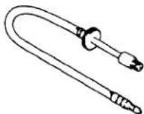
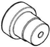
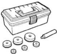
SPECIAL TOOLS
| Base Manual Tools | Kawasaki Recommend tools |
 09900-06107Snap ring pliers 09900-06107Snap ring pliers |  57001-144Outside circlip pliers 57001-144Outside circlip pliers |
 09900-06108Snap ring pliers 09900-06108Snap ring pliers | 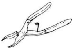 57001-143Inside circlip pliers 57001-143Inside circlip pliers |
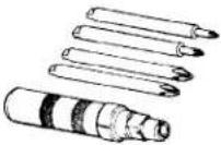 09900-09004Impact driver set 09900-09004Impact driver set | A suitablecommercially availableimpact driver set |
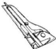 09900-20101 or09900-20102Vernier calipers 09900-20101 or09900-20102Vernier calipers | A suitablecommercially availablevernier calipers(150 mm) |
 09900-20202Micrometer(25 ~ 50 mm) 09900-20202Micrometer(25 ~ 50 mm) | A suitablecommercially availablemicrometer (25 ~ 50mm) |


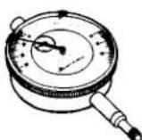
| Base Manual Tools | Kawasaki Recommend tools |
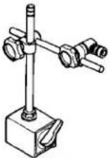 09900-20701Magnetic stand 09900-20701Magnetic stand | A suitablecommercially availablemagnetic stand |
 09900-2080309900-20806Thickness gauge 09900-2080309900-20806Thickness gauge | A suitablecommercially availablethickness gauge |
 09900-20805Tire depth gauge 09900-20805Tire depth gauge | A suitablecommercially availabletire depth gauge |
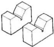 09900-21304V-block set (100 mm) 09900-21304V-block set (100 mm) | A suitablecommercially availableV-block set (100 mm) |
 09900-2230109900-22302Plastigauge 09900-2230109900-22302Plastigauge | A suitablecommercially availableplastigage (0.025 ~0.076 mm) |

natural_image
Line drawing of a box containing a tool kit with a ruler and ring (no text or symbols)
natural_image
Technical line drawing of a mechanical housing or enclosure with internal components (no text or symbols)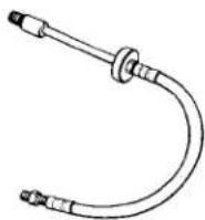

natural_image
Diagram of a mechanical component with multiple cylindrical pins and connecting rods (no text or symbols)

| Base Manual Tools | Kawasaki Recommend tools |
 |  |
| 09913-60230Journal bearingremover/installer | 57001-S065Journal bearingremover/installer |
 |  |
| 09913-60240Journal bearing holder | 57001-S066Journal bearing holder |
 | 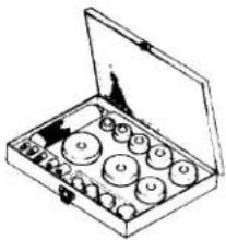 |
| 09913-70210Bearing installer set | 57001-1129Bearing driver set |
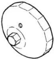 |  |
| 09915-40610Oil filter wrench | 57001-S067Oil filter wrench |
 |  |
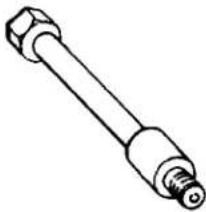
| 09915-64510Compression gaugeset | 57001-221Compression gauge, 20 kgf/cm2 |
natural_image
Line drawing of a mechanical bolt or screw assembly (no text or symbols)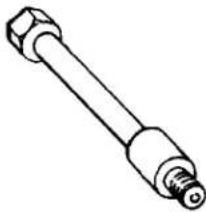
natural_image
Line drawing of a mechanical bolt or screw assembly (no text or symbols)
natural_image
Line drawing of a U-shaped tube with two connectors (no text or symbols)
natural_image
Line drawing of a U-shaped tube with two connectors (no text or symbols)
natural_image
Technical line drawing of a mechanical component with threaded end (no text or symbols)
natural_image
Technical line drawing of a mechanical component with threaded end (no text or symbols)
natural_image
Line drawing of a pressure gauge with handle and dial (no text or symbols)
natural_image
Line drawing of a pressure gauge with tubing (no text or symbols)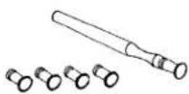
| Base Manual Tools | Kawasaki Recommend tools |
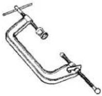 |  |
| 09916-14510Valve springcompressor presser | 57001-241Valve springcompressor assembly |
 |  |
| 09916-14910Valve springcompressor attachment | 57001-1586Valve spring compressoadapter, φ24 |
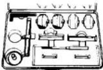 | 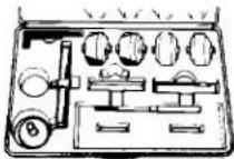 |
| 09916-21111Valve seat cutter set | 57001-S011Valve seat cutter set |
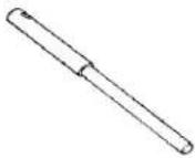 | 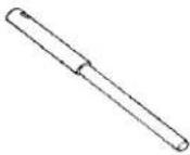 |
| 09916-24480Solid pilot(N-140-5.5 mm) | 57001-S070Solid pilot(N-140-5.5 mm) |
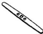
 |  |
| 09916-24210Valve seat cutter(N-615) | 57001-S071Valve seat cutter(N-615) |

natural_image
Technical line drawing of a mechanical component with no visible text or symbols
natural_image
Technical line drawing of a mechanical component with no visible text or symbols



natural_image
Simple line drawing of a pen or stylus (no text or symbols)


| Base Manual Tools | Kawasaki Recommend tools |
 | 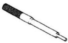 |
| 09916-44910Valve guideremover/installer | 57001-1021Valve guide arbor,φ 5.5 |
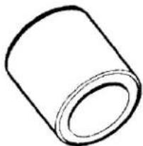 |  |
| 09916-53340Attachment | 57001-S074Attachment |
 | |
| 09916-84511Tweezers | A suitablecommercially availabletweezers |
 | |
| 09917-47010Vacuum pump gauge | A suitablecommerciallyavailable tool |
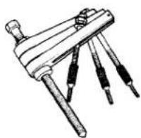 |  |
| 09920-13120Crankcaseseparating tool | 57001-1362Crankcase splittingtool assembly |

natural_image
Line drawing of a mechanical clamp or bracket (no text or symbols)
natural_image
Line drawing of a mechanical clamp or tool (no text or symbols)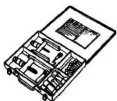
natural_image
Line drawing of a mechanical toolbox with internal compartments (no text or symbols)
natural_image
Illustration of various screwdriver tools including a drill bit, screwdriver, and pushpin (no text or labels)
natural_image
Technical line drawing of mechanical components including a box, cylindrical parts, and threaded rods (no text or labels)
natural_image
Illustration of mechanical components including a box, cylindrical parts, and threaded rods (no text or symbols)
natural_image
Technical line drawing of a screwdriver with threaded shaft and base (no text or symbols)
natural_image
Technical line drawing of a screwdriver with threaded shaft (no text or symbols)

natural_image
Illustration of various screwdriver tools including a drill bit, screwdriver, and pushpin (no text or labels present)| Base Manual Tools | Kawasaki Recommend tools |
 09924-74570Final drive gear bearing installer/remover 09924-74570Final drive gear bearing installer/remover | 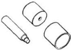 57001-S075Final drive gear bearing installer/remover 57001-S075Final drive gear bearing installer/remover |
 09924-84510Bearing installer set 09924-84510Bearing installer set |  57001-S044Bearing Installer Set 57001-S044Bearing Installer Set |
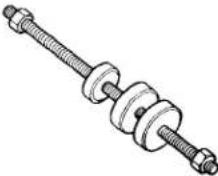 09924-84521Bearing installer set 09924-84521Bearing installer set |  57001-S023Bearing Installer Set 57001-S023Bearing Installer Set |
 09925-18011Steering bearing installer 09925-18011Steering bearing installer | 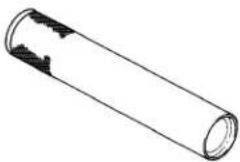 57001-137Steering Stem Bearing Driver 57001-137Steering Stem Bearing Driver |
 09930-11920Torx bit JT40H 09930-11920Torx bit JT40H | A suitable commercially available tool |


natural_image
Simple line drawing of a curved tool or rod (no text or symbols)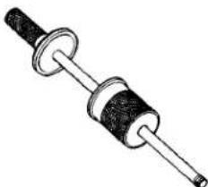
natural_image
Mechanical component diagram showing a shaft and housing with no visible text or symbols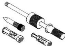
natural_image
Illustration of various screwdriver tools including a pen, screwdriver, and pushpin (no text or labels)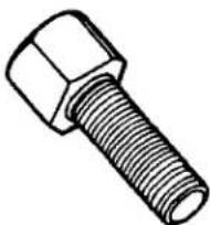

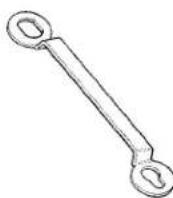

| Base Manual Tools | Kawasaki Recommend tools |
 |  |
| 09930-73110Starter torque limiter holder | 57001-S078Starter torque limiter holder |
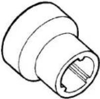 |  |
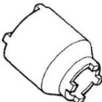
| 09930-73120Starter torque limiter socket | 57001-S079Starter torque limiter socket |
 | 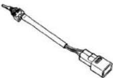 |
| 09930-82710Mode selection switch | 57001-S080Mode selection switch |
 |  |
| 09940-14911Steering stem nut wrench | 57001-S081Steering stem nut wrench |
 |  |
| 09940-14940Swingarm pivot thrust adjuster socket wrench | 57001-S082Swingarm pivot thrust adjuster socket wrench |


natural_image
Line drawing of a mechanical component with no text or symbols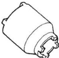
natural_image
Line drawing of a mechanical component with no text or symbols


natural_image
Simple line drawing of a cylindrical object with a circular end, resembling a pen or tool (no text or symbols)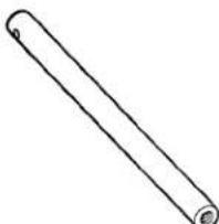
natural_image
Simple line drawing of a cylindrical object with a looped end (no text or symbols)| Base Manual Tools | Kawasaki Recommend tools |
 |  |
| 09940-52861Front fork oil seal installer set | 57001-S034Front fork oil seal installer set |
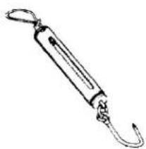 | |
| 099340-92720Spring scale | A suitable commercially available spring scale |
 |  |
| 09941-34513Steering race installer | 57001-1129Bearing driver set |

natural_image
Technical line drawing of a mechanical clamp or bracket component (no text or symbols)

natural_image
Simple line drawing of a mechanical device with a curved handle and two cylindrical components (no text or symbols)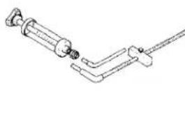
natural_image
Technical line drawing of a mechanical assembly with no visible text or symbols
natural_image
Technical line drawing of a mechanical component (no text or symbols)NOTE
When ordering a special tool, please confirm whether it is available or not.
Emission Control Information
Contents
EMISSION CONTROL SYSTEMS....Base Manual
FUEL INJECTION SYSTEM....Base Manual
CRANKCASE EMISSION CONTROL SYSTEM.... Base Manual
EXHAUST EMISSION CONTROL SYSTEM (PAIR SYSTEM) ...... Base Manual
NOISE EMISSION CONTROL SYSTEM ....... Base Manual
EVAPORATIVE EMISSION CONTROL SYSTEM (Only for E-33)...... Base Manual
PAIR (AIR SUPPLY) SYSTEM INSPECTION ....Base Manual
PAIR (AIR SUPPLY) SYSTEM HOSE ROUTING...... Base Manual
HEATED OXGEN SENSOR (HO₂S) INSPECTION...... Base Manual
HEATED OXGEN SENSOR WIRE ROUTING ...... Base Manual
EVAPORATIVE EMISSION CONTROL SYSTEM INSPECTION (Only for E-33) ...... Base Manual
CANISTER HOSE ROUTING (Only for E-33) ...... Base Manual
Base Manual
Suzuki DL1000
Note: Use the Kawasaki Service Manual Supplement along with the Suzuki Base Manual when servicing the Kawasaki KLV1000-A1 models.
FOREWORD
This manual contains an introductory description on the SUZUKI DL1000 and procedures for its inspection/service and overhaul of its main components.
Other information considered as generally known is not included.
Read the GENERAL INFORMATION section to familiarize yourself with the motorcycle and its maintenance. Use this section as well as other sections to use as a guide for proper inspection and service.
This manual will help you know the motorcycle better so that you can assure your customers of fast and reliable service.
* This manual has been prepared on the basis of the latest specifications at the time of publication. If modifications have been made since then, differences may exist between the content of this manual and the actual motorcycle.
* Illustrations in this manual are used to show the basic principles of operation and work procedures. They may not represent the actual motorcycle exactly in detail.
* This manual is written for persons who have enough knowledge, skills and tools, including special tools, for servicing SUZUKI motorcycles. If you do not have the proper knowledge and tools, ask your authorized SUZUKI motorcycle dealer to help you.
WARNING
Inexperienced mechanics or mechanics without the proper tools and equipment may not be able to properly perform the services described in this manual.
Improper repair may result in injury to the mechanic and may render the motorcycle unsafe for the rider and passenger.
GROUP INDEX
| GENERAL INFORMATION | 1 |
| PERIODIC MAINTENANCE | 2 |
| ENGINE | 3 |
| FI SYSTEM | 4 |
| COOLING AND LUBRICATION SYSTEM | 5 |
| CHASSIS | 6 |
| ELECTRICAL SYSTEM | 7 |
| SERVICING INFORMATION | 8 |
| EMISSION CONTROL INFORMATION | 9 |
| DL1000K3 ('03-MODEL) | 10 |
| DL1000K4 ('04-MODEL) | 11 |
| WIRING DIAGRAM | 12 |
SUZUKI MOTOR CORPORATION
HOW TO USE THIS MANUAL
TO LOCATE WHAT YOU ARE LOOKING FOR:
- The text of this manual is divided into sections.
- The section titles are listed in the GROUP INDEX.
- Holding the manual as shown at the right will allow you to find the first page of the section easily.
- The contents are listed on the first page of each section to help you find the item and page you need.
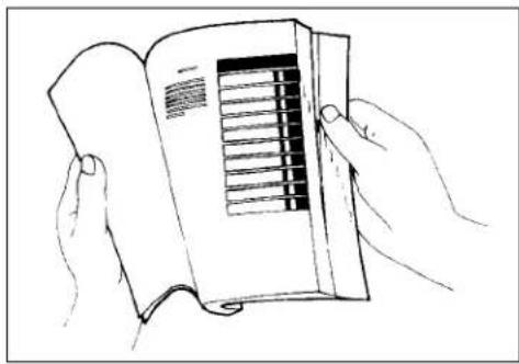
natural_image
Line drawing of two hands holding an open book with a grid of books on the cover (no text or symbols visible)COMPONENT PARTS AND WORK TO BE DONE
Under the name of each system or unit, is its exploded view. Work instructions and other service information such as the tightening torque, lubricating points and locking agent points, are provided.
Example: Front wheel
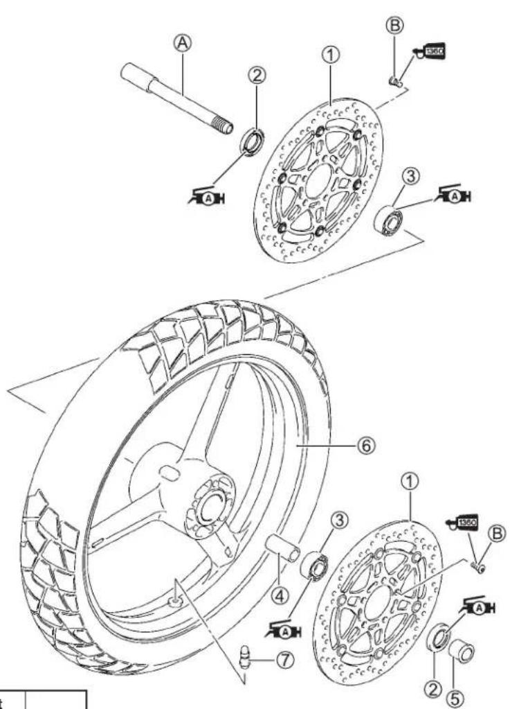
① Brake disc
② Dust seal
③ Bearing
④ Center spacer
⑤ Coller
⑥ Front wheel
⑦ Tire valve
Ⓐ Front axle
⑧ Brake disc bolt
U
| ITEM N·m kgf·m lb·ft | |||
| A | 100 | 10.0 72.5 | |
| B | 23 | 2.3 16.5 | |
SYMBOL
Listed in the table below are the symbols indicating instructions and other information necessary for servicing. The meaning of each symbol is also included in the table.
| SYMBOL | DEFINITION SYMBOL DEFINITION | ||
 | Torque control required. Data beside it indicates specified torque. | 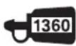 | Apply THREAD LOCK SUPER “1360”. 99000-32130 |
 | Apply oil. Use engine oil unless otherwise specified. |  | Use engine coolant. 99000-99032-11X |
 | Apply molybdenum oil solution. (Mixture of engine oil and SUZUKI MOLY PASTE in a ratio of 1:1) |  | Use fork oil. 99000-99001-SS8 |
 | Apply SUZUKI SUPER GREASE “A”. 99000-25010 |  | Apply or use brake fluid. |
 | Apply SUZUKI MOLY PASTE. 99000-25140 |  | Measure in voltage range. |
 | Apply SUZUKI BOND “1207B” 99000-31140 |  | Measure in current range. |
 | Apply SUZUKI BOND “1215”. 99000-31110 |  | Measure in diode test range. |
 | Apply THREAD LOCK SUPER “1303”. 99000-32030 |  | Measure in continuity test range. |
 | Apply THREAD LOCK SUPER “1322”. 99000-32110 |  | Use special tool. |
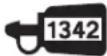 | Apply THREAD LOCK “1342”. 99000-32050 |  | Indication of service data. |
ABBREVIATIONS USED IN THIS MANUAL
A
ABDC : After Bottom Dead Center
AC : Alternating Current
ACL : Air Cleaner, Air Cleaner Box
API : American Petroleum Institute
ATDC : After Top Dead Center
ATM Pressure: Atmospheric Pressure
Atmospheric Pressure Sensor (APS)
A/F : Air Fuel Mixture
B
BBDC : Before Bottom Dead Center
BTDC : Before Top Dead Center
B+ : Battery Positive Voltage
C
CKP Sensor : Crankshaft Position Sensor (CKPS)
CKT : Circuit
CLP Switch : Clutch Lever Position Switch (Clutch Switch)
CMP Sensor : Camshaft Position Sensor (CMPS)
CO : Carbon Monoxide
CPU : Central Processing Unit
D
DC : Direct Current
ECT Sensor : Engine Coolant Temperature Sensor (ECTS), Water Temp. Sensor (WTS)
EVAP : Evaporative Emission
EVAP Canister : Evaporative Emission Canister (Canister)
F
FI : Fuel Injection, Fuel Injector
FP : Fuel Pump
FPR : Fuel Pressure Regulator
FP Relay : Fuel Pump Relay
G
GEN : Generator GND : Ground GP Switch : Gear Position Switch
H
HC : Hydrocarbons
|
IAP Sensor : Intake Air Pressure Sensor (IAPS)
IAT Sensor : Intake Air Temperature Sensor (IATS)
IG : Ignition
L
LCD : Liquid Crystal Display
LED : Light Emitting Diode (Malfunction Indicator Lamp)
LH : Left Hand
M
MAL-Code : Malfunction Code (Diagnostic Code)
Max : Maximum
MIL : Malfunction Indicator Lamp (LED)
Min : Minimum
N
NOx : Nitrogen Oxides
0
OHC : Over Head Camshaft
OPS : Oil Pressure Switch
P
PCV : Positive Crankcase Ventilation (Crankcase Breather)
R
RH : Right Hand
ROM : Read Only Memory
s
SAE : Society of Automotive Engineers
STC System : Secondary Throttle Control System (STCS)
STP Sensor : Secondary Throttle Position Sensor (STPS)
ST Valve : Secondary Throttle Valve (STV)
STV Actuator : Secondary Throttle Valve Actuator (STVA)
T
TO Sensor : Tip Over Sensor (TOS)
TP Sensor : Throttle Position Sensor (TPS)
V
VD : Vacuum Damper
GENERAL INFORMATION
CONTENTS
WARNING/CAUTION/NOTE 1-2
GENERAL PRECAUTIONS 1-2
SUZUKI DL1000K2 ('02-MODEL) 1-4
SERIAL NUMBER LOCATION 1-4
FUEL, OIL AND ENGINE COOLANT RECOMMENDATION ......1- 4
FUEL 1-4
ENGINE OIL 1-5
BRAKE FLUID 1-5
FRONT FORK OIL 1-5
ENGINE COOLANT 1-5
WATER FOR MIXING 1-5
ANTI-FREEZE/ENGINE COOLANT 1-5
LIQUID AMOUNT OF WATER/ENGINE COOLANT ....1- 5
BREAK-IN PROCEDURES 1-6
CYLINDER IDENTIFICATION 1-6
INFORMATION LABELS 1-7
SPECIFICATIONS 1-8
COUNTRY AND AREA CODES 1-10
WARNING/CAUTION/NOTE
Please read this manual and follow its instructions carefully. To emphasize special information, the symbol and the words WARNING, CAUTION and NOTE have special meanings. Pay special attention to the messages highlighted by these signal words.
WARNING
Indicates a potential hazard that could result in death or injury.
CAUTION
Indicates a potential hazard that could result in motorcycle damage.
NOTE:
Indicates special information to make maintenance easier or instructions clearer.
Please note, however, that the warnings and cautions contained in this manual cannot possibly cover all potential hazards relating to the servicing, or lack of servicing, of the motorcycle. In addition to the WARNINGS and CAUTIONS stated, you must use good judgement and basic mechanical safety principles. If you are unsure about how to perform a particular service operation, ask a more experienced mechanic for advice.
GENERAL PRECAUTIONS
WARNING
* Proper service and repair procedures are important for the safety of the service mechanic and the safety and reliability of the motorcycle.
* When 2 or more persons work together, pay attention to the safety of each other.
* When it is necessary to run the engine indoors, make sure that exhaust gas is forced outdoors.
* When working with toxic or flammable materials, make sure that the area you work in is well-ventilated and that you follow all of the material manufacturer's instructions.
* Never use gasoline as a cleaning solvent.
* To avoid getting burned, do not touch the engine, engine oil, radiator and exhaust system until they have cooled.
* After servicing the fuel, oil, water, exhaust or brake systems, check all lines and fittings related to the system for leaks.
CAUTION
* If parts replacement is necessary, replace the parts with Suzuki Genuine Parts or their equivalent.
* When removing parts that are to be reused, keep them arranged in an orderly manner so that they may be reinstalled in the proper order and orientation.
* Be sure to use special tools when instructed.
* Make sure that all parts used in reassembly are clean. Lubricate them when specified.
* Use the specified lubricant, bond, or sealant.
* When removing the battery, disconnect the negative cable first and then the positive cable.
* When reconnecting the battery, connect the positive cable first and then the negative cable, and replace the terminal cover on the positive terminal.
* When performing service to electrical parts, if the service procedures not require use of battery power, disconnect the negative cable the battery.
* When tightening the cylinder head and case bolts and nuts, tighten the larger sizes first. Always tighten the bolts and nuts diagonally from the inside toward outside and to the specified tightening torque.
* Whenever you remove oil seals, gaskets, packing, O-rings, locking washers, self-locking nuts, cotter pins, circlips and certain other parts as specified, be sure to replace them with new ones. Also, before installing these new parts, be sure to remove any left over material from the mating surfaces.
* Never reuse a circlip. When installing a new circlip, take care not to expand the end gap larger than required to slip the circlip over the shaft. After installing a circlip, always ensure that it is completely seated in its groove and securely fitted.
* Use a torque wrench to tighten fasteners to the specified torque. Wipe off grease and oil if a thread is smeared with them.
* After reassembling, check parts for tightness and proper operation.
* To protect the environment, do not unlawfully dispose of used motor oil, engine coolant and other fluids: batteries, and tires.
* To protect Earth's natural resources, properly dispose of used motorcycle and parts.
SUZUKI DL1000K2 ('02-MODEL)

natural_image
Side profile of a Vaxi motorcycle with visible engine and wheel (no text or symbols)RIGHT SIDE

natural_image
Side profile of a silver and black motorcycle with visible engine and wheel (no text or symbols)LEFT SIDE
* Difference between photographs and actual motorcycles depends on the markets.
SERIAL NUMBER LOCATION
The frame serial number or V.I.N. (Vehicle Identification Number) ① is stamped on the right side of the steering head pipe. The engine serial number ② is located on the right side of the crankcase. These numbers are required especially for registering the machine and ordering spare parts.

natural_image
Close-up of a car engine bay with hoses and control panel (no visible text or symbols)
FUEL, OIL AND ENGINE COOLANT RECOMMENDATION FUEL (FOR CANADIAN MODEL)
Use only unleaded gasoline of at least 87 pump octane ( 2 pM91 octane or higher rated by the research method.
Gasoline containing MTBE (Methyl Tertiary Butyl Ether), less than 10% ethanol, or less than 5% methanol with appropriate cosolvents and corrosion inhibitor is permissible.
FUEL (FOR OTHER COUNTRIES)
Gasoline used should be graded 91 octane (Research Method) or higher. Unleaded gasoline is recommended.
ENGINE OIL
Use a premium quality 4-stroke motor oil to ensure longer service life of your motorcycle. Use only oils which are rated SF or SG under the API service classification. The recommended viscosity is SAE 10W-40. If an SAE 10W-40 motor oil is not available, select an alternative according to the following chart.

BRAKE FLUID
Specification and classification: DOT 4
WARNING
Since the brake system of this motorcycle is filled with a glycol-based brake fluid by the manufacturer, do not use or mix different types of fluid such as silicone-based and petroleum-based fluid for refilling the system, otherwise serious damage will result.
Do not use any brake fluid taken from old or used or unsealed containers.
Never re-use brake fluid left over from a previous servicing, which has been stored for a long period.
FRONT FORK OIL
Use fork oil SS8 or an equivalent fork oil.
ENGINE COOLANT
Use an anti-freeze/engine coolant compatible with an aluminum radiator, mixed with distilled water only.
WATER FOR MIXING
Use distilled water only. Water other than distilled water can corrode and clog the aluminum radiator.
ANTI-FREEZE/ENGINE COOLANT
The engine coolant perform as a corrosion and rust inhibitor as well as anti-freeze. Therefore, the engine coolant should be used at all times even though the atmospheric temperature in your area does not go down to freezing point.
Suzuki recommends the use of SUZUKI COOLANT anti-freeze/engine coolant. If this is not available, use an equivalent which is compatible with an aluminum radiator.
LIQUID AMOUNT OF WATER/ENGINE COOLANT
Solution capacity (total): 2 200 ml (2.3/1.9 US/lmp qt)
For engine coolant mixture information, refer to cooling system section, page 5-2.
CAUTION
Mixing of anti-freeze/engine coolant should be limited to 60%. Mixing beyond it would reduce its efficiency. If the anti-freeze/engine coolant mixing ratio is below 50%, rust inhabiting performance is greatly reduced. Be sure to mix it above 50% even though the atmospheric temperature does not go down to the freezing point.
BREAK-IN PROCEDURES
During manufacture only the best possible materials are used and all machined parts are finished to a very high standard but it is still necessary to allow the moving parts to “BREAK-IN” before subjecting the engine to maximum stresses. The future performance and reliability of the engine depends on the care and restraint exercised during its early life. The general rules are as follows.
- Keep to these break-in engine speed limits:
Initial 800 km ( 500 miles): Below 4 500 r/min
Up to 1 600 km (1 000 miles): Below 7 000 r/min
Over 1 600 km (1 000 miles): Below 9 500 r/min
- Upon reaching an odometer reading of 1 600 km (1 000 miles) you can subject the motorcycle to full throttle operation. However, do not exceed 9 500 r/min at any time.
CYLINDER IDENTIFICATION
The two cylinders of this engine are identified as No.1 and No.2 cylinder, as counted from front to rear (as viewed by the rider on the seat).

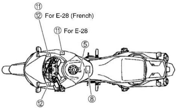
INFORMATION LABELS
| 1 Noise label (For E-03, 24, 33) |
| 2 Information label (For E-03, 28, 33) |
| 3 ICES Canada label (For E-28) |
| 4 Vacuum hose routing label (For E-33) |
| 5 Fuel caution label (For E-02, 24) |
| 6 Manual notice label (For E-03, 33) |
| 7 Tire pressure label |
| 8 Warning safety label |
| 9 Rear carrier warning label |
| 10 Frame caution label |
| 11 Steering warning label |
| 12 Screen warning label |
| 13 ID label (For E-02, 19, 24) |
| 14 Safety label (For E-03, 28, 33) |
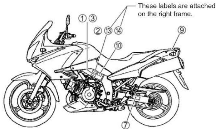

SPECIFICATIONS
DIMENSIONS AND DRY MASS
Overall length....2 295 mm (90.4 in)
Overall width 865 mm (34.1 in)
Overall height....1 335 mm (52.6 in)
Wheelbase....1 535 mm (60.4 in)
Ground clearance 165 mm (6.5 in)
Seat height.... 840 mm (33.1 in)
Dry mass.... 207 kg (456 lbs)
209 kg (461 lbs) .....E-33
ENGINE
Type Four-stroke, Liquid-cooled, DOHC, 90-degree V-twin
Number of cylinders....2
Bore 98.0 mm (3.858 in)
Stroke....66.0 mm (2.598 in)
Piston displacement....996 cm 3 (60.8 cu. in)
Compression ratio....11.3 : 1
Fuel system....Fuel injection system
Air cleaner....Non-woven fabric element
Starter system.....Electric starter
Lubrication system......Wet sump
DRIVE TRAIN
Clutch....Wet multi-plate type
Transmission....6-speed constant mesh
Gearshift pattern ....1-down, 5-up
Primary reduction ratio....1.838 (57/31)
Final reduction ratio 2.411 (41/17)
Gear ratios, Low....3.000 (36/12)
2nd....1.933 (29/15)
3rd 1.500 (27/18)
4th....1.227 (27/22)
5th....1.086 (25/23)
Top 0.913 (21/23)
Drive chain....RK525 SMOZ7, 112 links
CHASSIS
Front suspension...... Inverted telescopic, coil spring, oil damped
Rear suspension.... Link type, coil spring, oil damped
Steering angle.... 40° (right & left)
Caster.... 26° 30'
Trail 111 mm (4.3 in)
Turning radius 2.7 m (8.86 ft)
Front brake.... Disc brake, twin
Rear brake .... Disc brake
Front tire size 110/80 R19M/C 59H, tubeless
Rear tire size.... 150/70 R17M/C 69H, tubeless
Front fork stroke 160 mm (6.3 in)
Rear wheel travel 159 mm (6.2 in)
ELECTRICAL
Ignition type ...... Electronic ignition (ECM, Transistorized)
Ignition timing 4° B. T. D. C at 1 200 r/min
Spark plug ...... NGK: CR8EK or DENSO: U24ETR
Battery.... 12 V 43.2 kC (12 Ah)/10 HR
Generator.... Three-phase A.C. Generator
Fuse 30/15/15/15/15/15/10 A
Headlight.... 12 V 60/55 W H4
Position light.... 12 V 5 W × 2.....Except for E-03, 24, 28, 33
Turn signal light.... 12 V 10 W
License light 12 V 5 W
Brake light/Taillight.... 12 V 21/5 W ×2
Speedometer/Tachometer light...... LED
Neutral indicator light ...... LED
High beam indicator light...... LED
Turn signal indicator light ...... LED
Over drive indicator light ...... LED
Fuel injector warning light ...... LED
Engine coolant temperature warning light...... LED
Oil pressure warning light...... LED
CAPACITIES
Fuel tank 22 L (5.8/4.8 US/Imp gal)
Engine oil, oil change 2700 ml (2.9/2.4 US/Imp qt)
with filter change.... 2 900 ml (3.1/2.6 US/Imp qt)
overhaul.... 3 300 ml (3.5/2.9 US/Imp qt)
Engine coolant, including reserve 2 200 ml (2.3/1.9 US/lmp oz)
Front fork oil (each leg) 505 ml (17.1/17.8 US/Imp oz)
These specifications are subject to change without notice.
COUNTRY AND AREA CODES
The following codes stand for the applicable country(-ies) and area(-s).
| CODE COUNTRY | or AREA |
| E-02 | U. K. |
| E-03 | U. S. A. (Except for California) |
| E-19 | EU |
| E-24 | Australia |
| E-28 | Canada |
| E-33 | California (U. S. A.) |
PERIODIC MAINTENANCE
CONTENTS
PERIODIC MAINTENANCE SCHEDULE 2-2
PERIODIC MAINTENANCE CHART 2-2
LUBRICATION POINTS 2-3
MAINTENANCE AND TUNE-UP PROCEDURES ......2- 4
AIR CLEANER 2-4
SPARK PLUG 2-5
TAPPET CLEARANCE 2-7
FUEL HOSE 2-12
ENGINE OIL AND OIL FILTER 2-12
ENGINE IDLE SPEED 2-14
THROTTLE CABLE PLAY 2-14
THROTTLE VALVE SYNCHRONIZATION 2-15
PAIR (AIR SUPPLY) SYSTEM 2-15
CLUTCH 2-16
COOLING SYSTEM 2-17
DRIVE CHAIN 2-19
BRAKE 2-21
TIRE 2-25
STEERING 2-25
FRONT FORK 2-26
REAR SUSPENSION 2-26
EXHAUST PIPE BOLT 2-26
CHASSIS BOLT AND NUT 2-27
COMPRESSION PRESSURE CHECK 2-29
COMPRESSION TEST PROCEDURE 2-29
OIL PRESSURE CHECK 2-30
OIL PRESSURE TEST PROCEDURE 2-30
PERIODIC MAINTENANCE SCHEDULE
The chart below lists the recommended intervals for all the required periodic service work necessary to keep the motorcycle operating at peak performance and economy. Mileages are expressed in terms of kilometers, miles and time for your convenience.
NOTE:
More frequent servicing may be performed on motorcycles that are used under severe conditions.
PERIODIC MAINTENANCE CHART
| Item\Interval | km | 1 000 6 000 12 000 | 18 000 24 000 | |||
| miles | 600 4 000 7 500 11 | 000 15 000 | ||||
| months 1 | 6 12 18 24 | |||||
| Air cleaner element — I I R I | ||||||
| Exhaust pipe bolts and muffler bolts | T — | T — | T | |||
| Valve clearance | — | — | — | — | I | |
| Spark plugs | — I R I R | |||||
| Fuel hose | — I I I I | |||||
| Replace every 4 years | ||||||
| Engine oil | R | R | R | R | R | |
| Engine oil filter | R | — | — | R | — | |
| Idle speed | I | I | I | I | I | |
| Throttle cable play | I I I | I I | ||||
| Throttle valve synchronization | I — I — I(E-33 only) | |||||
| Evaporative emission control system(E-33 only) | — | — | I | — | I | |
| Replace vapor hose every 4 years | ||||||
| PAIR(air supply)system | — | — | I | — | I | |
| Engine coolant | Replace every 2 years. | |||||
| Radiator hose | — I I I I | |||||
| Clutch hose | — I I I I | |||||
| Replace every 4 years | ||||||
| Clutch fluid | — I I I I | |||||
| Replace every 2 years | ||||||
| Drive chain | I | I | I | I | I | |
| Clean and lubricate every 1 000 km (600 miles) | ||||||
| Brakes | I | I | I | I | I | |
| Brake hose | — I I | I I | ||||
| Replace every 4 years | ||||||
| Brake fluid | — I I | I I | ||||
| Replace every 2 years | ||||||
| Tires | — | I | I | I | I | |
| Steering | I | — | I | — | I | |
| Front fork | — | — | I | — | I | |
| Rear suspension | — | — I | — I | |||
| Chassis bolts and nuts | T T | T | T T | |||
NOTE:
I=Inspect and clean, adjust, replace or lubricate as necessary;
R=Replace; T=Tighten
LUBRICATION POINTS
Proper lubrication is important for smooth operation and long life of each working part of the motorcycle. Major lubrication points are indicated below.


NOTE:
* Before lubricating each part, clean off any rusty spots and wipe off any grease, oil, dirt or grime.
* Lubricate exposed parts which are subject to rust, with a rust preventative spray whenever the motorcycle has been operated under wet or rainy conditions.
MAINTENANCE AND TUNE-UP PROCEDURES
This section describes the servicing procedures for each item of the Periodic Maintenance requirements.
AIR CLEANER
Inspect every 6 000 km (4 000 miles, 6 months) and replace every 18 000 km (11 000 miles, 18 months).
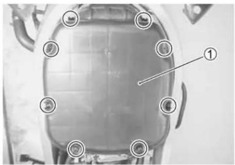
- Remove the seat. (6-4)
- Remove the fuel tank. (4-52)
- Remove the air cleaner box cap ①.
- Remove the air cleaner element ②.
- Carefully use air hose to blow the dust from the cleaner element.
CAUTION
Always use air pressure on the throttle body side of the air cleaner element. If air pressure is used on the other side, dirt will be forced into the pores of the air cleaner element thus restricting air flow through the air cleaner element.
• Install the O-ring ③ properly.
- Reinstall the cleaned or new air cleaner element in the reverse order of removal.
CAUTION
If driving under dusty condition, clean the air cleaner element more frequently. The surest way to accelerate engine wear is to use the engine without the element or to use a ruptured element. Make sure that the air cleaner is in good condition at all times. Life of the engine depends largely on this component!
natural_image
Top-down view of a car's front bumper with numbered callouts highlighting the interior area (no text or symbols present)
natural_image
Interior view of a vehicle air vent with visible airflow and engine components (no text or symbols)
natural_image
Close-up of a hand holding a rectangular electronic component with a grid-like structure, mounted on a dark tray (no visible text or symbols)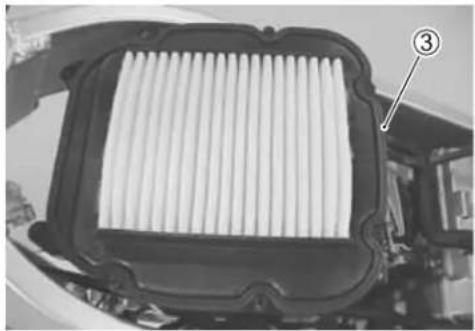
natural_image
Close-up of a mechanical component with internal parallel grooves and a numbered label (3) pointing to a feature, no readable text or symbols present.NOTE:
When cleaning the air cleaner element, drain water from the air cleaner by removing the drain plug.
SPARK PLUG
Inspect every 6 000 km (4 000 miles, 6 months) and replace every 12 000 km (7 500 miles, 12 months).
NO.1 (FRONT) SPARK PLUG REMOVAL
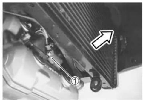
- Remove the spark plug mounting bolts ① and ②.
- Move the radiator forward.
- Remove the spark plug cap ①.
NOTE:
Be careful not to damage the radiator fins.
WARNING
The hot radiator and the hot engine can burn you. Wait until the radiator and the engine are cool enough to touch.
- Remove the spark plug with a spark plug wrench.

natural_image
Close-up of a car engine bay with visible structural components and a white arrow pointing to a specific component (no text or symbols present)
natural_image
Close-up of a car's engine compartment with a labeled component (A) and a circular detail on the wheel (no text or symbols beyond label)
natural_image
Close-up of a mechanical component with a numbered annotation and an arrow pointing to a detail (no readable text or symbols)
natural_image
Close-up of mechanical components and tools, no visible text or symbolsNO.2 (REAR) SPARK PLUG REMOVAL
- Remove the seat. (6-4)
- Lift and support the fuel tank. (4-51)
- Remove the spark plug cap.
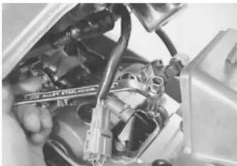
- Remove the spark plug with a spark plug wrench.
natural_image
Close-up of a car engine bay with visible hoses and components (no text or symbols)HEAT RANGE
- Check to see the heat range of the plug.
| Standard Cold type | |
| NGK CR8EK CR9EK or CR10EK | |
| DENSO U24ETR U27ETR or U31ETR | |
CARBON DEPOSIT
- Check to see if there are carbons deposit on the plugs. If carbon is deposited, remove it with a spark plug cleaner machine or carefully using a tool with a pointed end.
SPARK PLUG GAP
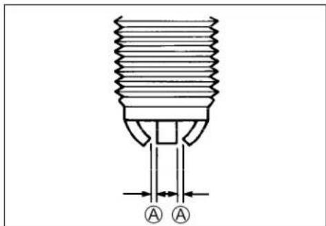
- Measure the plug gap with a thickness gauge. If out of specification, adjust it to the following gap.

09900-20803: Thickness gauge

Spark plug gap®
Standard: 0.6 - 0.7 mm (0.024 - 0.028 in)
ELECTRODES CONDITION
- Check to see the worn or burnt condition of the electrodes. If it is extremely worn or burnt, replace the plug. And also replace the plug if it has a broken insulator, damaged thread.
CAUTION
Confirm the thread size and reach when replacing the plug. If the reach is too short, carbon will be deposited on the screw portion of the plug hole and engine damage may result.

natural_image
Line drawing of hands using a compass to draw a small object (no text or symbols present)SPARK PLUG AND PLUG CAP INSTALLATION
CAUTION
Before using a spark plug wrench, carefully turn the spark plug by finger into the threads of the cylinder head to prevent damage the aluminum threads.
• Install the spark plugs to the cylinder heads by finger tight, and then tighten them to the specified torque.

Spark plug: 11 N·m (1.1 kgf-m, 8.0 lb-ft)
NOTE:
When fitting the spark plug caps, front and rear, face the triangle mark Ⓐ on the water-proof cover to each cylinder exhaust side.
TAPPET CLEARANCE
Inspect every 24 000 km (15 000 miles, 24 months).
- Remove the seat. (6-4)
- Lift and support the fuel tank. (4-51)
- Remove the fuel tank side covers, cowlings and inner cover. (6-6)
- Remove the radiator. (5-4)
- Remove the spark plugs. (2-5)
- Remove the cylinder head covers.
The tappet clearance specification is different for intake and exhaust valves.
Tappet clearance must be checked and adjusted, 1) at the time of periodic inspection, 2) when the valve mechanism is serviced, and 3) when the camshafts are disturbed by removing them for servicing.

Tappet clearance (when cold)
IN.: 0.10 - 0.20 mm (0.004 - 0.008 in)
EX.: 0.20 - 0.30 mm (0.008 - 0.012 in)
NOTE:
* The tappet clearance should be taken when each cylinder is at Top Dead Center (TDC) of compression stroke.
* The cams (IN & EX) on the front cylinder at position Ⓐ show the front cylinder at TDC of compression stroke.
* The cams (IN & EX) on the rear cylinder at position Ⓑ show the rear cylinder at TDC of compression stroke.
* The clearance specification is for COLD state.
* To turn the crankshaft for clearance checking, be sure to use a 17-mm wrench, and rotate in the normal running direction. All spark plugs should be removed.
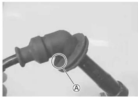
natural_image
Close-up of a black electric plug with labeled component A (no text or symbols beyond labels)
natural_image
Close-up of mechanical components with circular annotations highlighting specific parts (no readable text or symbols)
natural_image
Close-up of a mechanical engine component with four circular arrows indicating directional changes (no text or symbols present)
- Remove the generator cover plug ① and timing inspection plug ②.
- Turn the crankshaft to set the No.1 (Front) cylinder at TDC of compression stroke. (Align the "F | T" line on the generator rotor to the index mark of valve timing inspection hole and also bring the camshafts to the position as shown in page 2-7.)
- To inspect the No.1 (Front) cylinder tappet clearance, use a thickness gauge between the tappet and the cam. If the clearance is out of specification, adjust it into the specified range.

09900-20803: Thickness gauge
- Turn the crankshaft 270 degrees ( 34 turns) to set the No.2 (Rear) cylinder at TDC of compression stroke. (Align the "R | T" line on the generator rotor to the index mark of valve timing inspection hole and also bring the camshafts to the position as shown in page 2-7.)
- Inspect the No.2 (Rear) cylinder tappet clearance as the same manner of No.1 (Front) cylinder and adjust the clearance if necessary.

09900-20803: Thickness gauge

natural_image
Close-up of a mechanical component with numbered annotations (1 and 2), no readable text or symbols present.
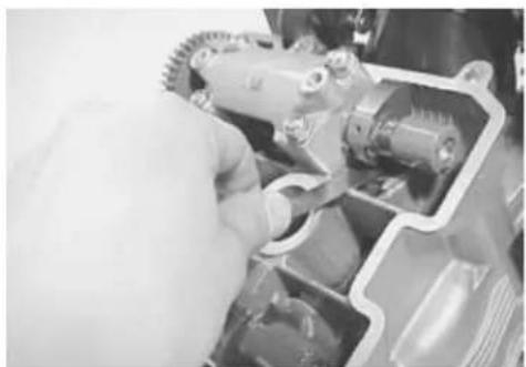
natural_image
Close-up of a hand operating a mechanical gear assembly (no visible text or symbols)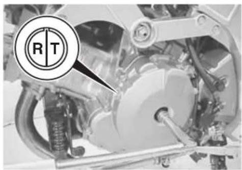

natural_image
Close-up of a car engine component being adjusted, with a tool labeled 'TOOL' pointing to the valve (no other text or symbols visible)TAPPET CLEARANCE ADJUSTMENT
The clearance is adjusted by replacing the existing tappet shim by a thicker or thinner shim.
- Remove the intake or exhaust camshafts. (3-20)
- Remove the tappet and shim by fingers or magnetic hand.
- Check the figures printed on the shim. These figures indicate the thickness of the shim, as illustrated.
- Select a replacement shim that will provide a clearance within the specified range. For the purpose of this adjustment, a total of 25 sizes of tappet shim are available ranging from 2.30 to 3.50 mm in steps of 0.05 mm . Fit the selected shim to the valve stem end, with numbers toward tappet. Be sure to check shim size with micrometer to ensure its size. Refer to the tappet shim selection table (Pages 2-10 and -11) for details.
NOTE:
* Be sure to apply engine oil to tappet shim top and bottom faces.
* When seating the tappet shim, be sure to face figure printed surface to the tappet.
CAUTION
Reinstall the camshafts as the specified manner. (3-105)
- After replacing the tappet shim and camshafts, rotate the engine so that the tappet is depressed fully. This will squeeze out oil trapped between the shim and the tappet that could cause an incorrect measurement, then check the clearance again to confirm that it is within the specified range.
- After finishing the tappet clearance adjustment, reinstall the following items.
- When installing the cylinder head cover, do not forget the gasket Ⓐ.
Page
* Cylinder head cover 3-111
* Spark plug and plug cap.... 2-7
* Valve timing inspection plug.... 3-111
* Generator cover plug.... 3-112
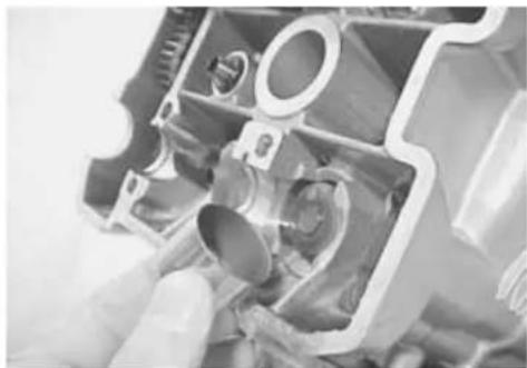
natural_image
Close-up of a mechanical component with a hand inserting a cylindrical part (no visible text or symbols)

natural_image
Pure mechanical cross-section diagram without any text, numbers, or symbols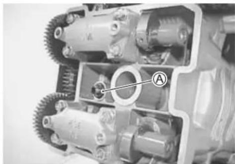
natural_image
Cross-sectional view of a mechanical assembly showing gears and shafts (no visible text or symbols)(INTAKE SIDE)
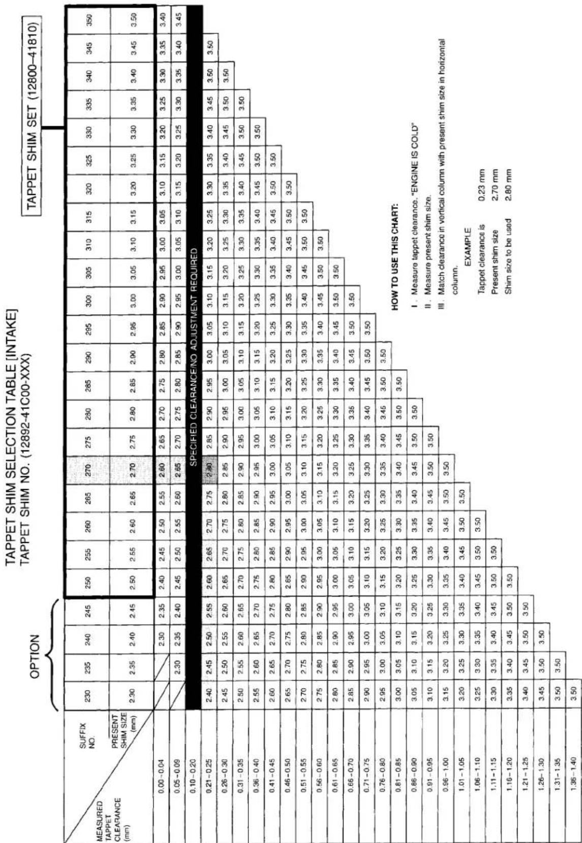
other
TAPPET SHIM SELECTION TABLE [INTAKE] TAPPET SHIM NO. (12892-41C00-XXX) TAPPET SHIM SET (12800-41810) OPTION MEASURED TAPPET CLEARANCE (mm) SUFFIX NO. 230 235 240 245 250 255 260 265 270 275 280 285 290 295 300 305 310 315 320 325 330 335 340 345 350 PRESENT SHIM SIZE (mm) 2.30 2.35 2.40 2.45 2.50 2.60 2.65 2.70 2.75 2.80 2.85 2.90 2.95 3.00 3.05 3.10 3.15 3.20 3.25 3.30 3.35 3.40 3.45 3.50 0.00-0.04 0.05-0.09 0.10-0.20 SPECIFIED CLEARANCE/NO ADJUSTMENT REQUIRED 0.21-0.25 0.26-0.30 0.31-0.35 0.36-0.40 0.41-0.45 0.46-0.50 0.51-0.55 0.56-0.60 0.61-0.65 0.66-0.70 0.71-0.75 0.76-0.80 0.81-0.85 0.86-0.90 0.91-0.95 0.96-1.00 1.01-1.05 1.06-1.10 1.11-1.15 1.16-1.20 1.21-1.25 1.26-1.30 1.31-1.35 1.36-1.40 HOW TO USE THIS CHART: I . Measure tappet clearance, "ENGINE IS COLD" II . Measure present shim size. III . Match clearance in vertical column with present shim size in horizontal column. EXAMPLE Tappet clearance is 0.23 mm Present shim size 2.70 mm Shim size to be used 2.80 mm(EXHAUST SIDE)
| SUFFIXNO | 230 | 235 | 240 | 245 | 250 | 255 | 260 | 265 | 270 | 275 | 280 | 285 | 290 | 295 | 300 | 305 | 310 | 315 | 320 | 325 | 330 | 335 | 340 | 345 | 350 |
| PRESENTSHIM SIZE(mm) | 2.30 | 2.35 | 2.40 | 2.45 | 2.50 | 2.550 | 2.60 | 2.65 | 2.70 | 2.75 | 2.80 | 2.85 | 2.90 | 2.95 | 3.00 | 3.05 | 3.10 | 3.15 | 3.20 | 3.25 | 3.30 | 3.35 | 3.40 | 3.45 | 3.50 |
| 0.00-0.04 | 2.30 | 2.35 | 2.40 | 2.45 | 2.50 | 2.55 | 2.60 | 2.65 | 2.70 | 2.75 | 2.80 | 2.85 | 2.90 | 2.95 | 3.00 | 3.05 | 3.10 | 3.15 | 3.20 | 3.25 | 3.30 | ||||
| 0.05-0.09 | 2.30 | 2.35 | 2.40 | 2.45 | 2.50 | 2.55 | 2.60 | 2.65 | 2.70 | 2.75 | 2.80 | 2.85 | 2.90 | 2.95 | 3.00 | 3.05 | 3.10 | 3.15 | 3.20 | 2.25 | 3.30 | 3.35 | |||
| 0.10-0.14 | 2.30 | 2.35 | 2.40 | 2.45 | 2.50 | 2.55 | 2.60 | 2.65 | 2.70 | 2.75 | 2.80 | 2.85 | 2.90 | 2.95 | 3.00 | 3.05 | 3.10 | 3.15 | 3.20 | 3,25 | 3.30 | 3.35 | 3.40 | ||
| 0.15-0.19 | 2.30 | 2.35 | 2.40 | 2.45 | 2.50 | 2.55 | 2.60 | 2.65 | 2.70 | 2.75 | 2.80 | 2.85 | 2.90 | 2.95 | 3.00 | 3.05 | 3.10 | 3.15 | 3.20 | 3.35 | 3.30 | 3.35 | 3.40 | 3.45 | |
| 0.20-0.30 | SPECIFIED CLEARANCE/NO ADJUSTMENT REQUIRED | ||||||||||||||||||||||||
| 0.31-0.35 | 2.40 | 2.45 | 2.50 | 2.55 | 2.60 | 2.65 | 2.70 | 2.75 | 2.80 | 2.85 | 2.90 | 2.95 | 3.00 | 3.05 | 3.10 | 3.15 | 3.20 | 3.25 | 3.30 | 3.35 | 3.40 | 3.45 | 3.50 | 3.50 | |
| 0.36-0.40 | 2.45 | 2.50 | 2.55 | 2.60 | 2.65 | 2.70 | 2.75 | 2.80 | 2.85 | 2.90 | 2.95 | 3.00 | 3.05 | 3.10 | 3.15 | 3.20 | 3.25 | 3.30 | 3.35 | 4.40 | 3.45 | 3.50 | 3.50 | ||
| 0.41-0.45 | 2.50 | 2.55 | 2.60 | 2.65 | 2.70 | 2.75 | 2.80 | 2.85 | 2.90 | 2.95 | 3.00 | 3.05 | 3.10 | 3.15 | 3.20 | 3.25 | 3.30 | 3.35 | 3.40 | 4.45 | 3.50 | 3.50 | |||
| 0.46-0.50 | 2.55 | 2.60 | 2.65 | 2.70 | 2.75 | 2.80 | 2.85 | 2.90 | 2.95 | 3.00 | 3.05 | 3.10 | 3.15 | 3.20 | 3.25 | 3.30 | 3.35 | 3.40 | 3.45 | 4.45 | 3.50 | 3.50 | |||
| 0.51-0.55 | 2.60 | 2.65 | 2.70 | 2.75 | 2.80 | 2.85 | 2.90 | 2.95 | 3.00 | 3.05 | 3.10 | 3.15 | 3.20 | 3.25 | 3.30 | 3.35 | 3.40 | 3.45 | 3.50 | 4.50 | 3.50 | ||||
| 0.56-0.60 | 2.65 | 2.70 | 2.75 | 2.80 | 2.85 | 2.90 | 2.95 | 3.00 | 3.05 | 3.10 | 3.15 | 3.20 | 3.25 | 3.30 | 3.35 | 3.40 | 3.45 | 3.50 | 3.50 | ||||||
| 0.61-0.65 | 2.70 | 2.75 | 2.80 | 2.85 | 2.90 | 2.95 | 3.00 | 3.05 | 3.10 | 3.15 | 3.20 | 3.25 | 3.30 | 3.35 | 3.40 | 3.45 | 3.50 | 3.50 | |||||||
| 0.66-0.70 | 2.75 | 2.80 | 2.85 | 2.90 | 2.95 | 3.00 | 3.05 | 3.10 | 3.15 | 3.20 | 3.25 | 3.30 | 3.35 | 3.40 | 3.45 | 3.50 | 3.50 | ||||||||
| 0.71-0.75 | 2.80 | 2.85 | 2.90 | 2.95 | 3.00 | 3.05 | 3.10 | 3.15 | 3.20 | 3.25 | 3.30 | 3.35 | 3.40 | 3.45 | 3.50 | 3.50 | |||||||||
| 0.76-0.80 | 2.85 | 2.90 | 2.95 | 3.00 | 3.05 | 3.10 | 3.15 | 3.20 | 3.25 | 3.30 | 3.35 | 3.40 | 3.45 | 3.50 | 3.50 | ||||||||||
| 0.81-0.85 | 2.90 | 2.95 | 3.00 | 3.05 | 3.10 | 3.15 | 3.20 | 3.25 | 3.30 | 3.35 | 3.40 | 3.45 | 3.50 | 3.50 | |||||||||||
| 0.86-0.90 | 2.95 | 3.00 | 3.05 | 3.10 | 3.15 | 3.20 | 3.25 | 3.30 | 3.35 | 3.40 | 3.45 | 3.50 | 3.50 | ||||||||||||
| 0.91-0.95 | 3.00 | 3.05 | 3.10 | 3.15 | 3.20 | 3.25 | 3.30 | 3.35 | 3.40 | 3.45 | 3.50 | 3.50 | |||||||||||||
| 0.96-1.00 | 3.05 | 3.10 | 3.15 | 3.20 | 3.25 | 3.30 | 3.35 | 3.40 | 3.45 | 3.50 | 3.50 | ||||||||||||||
| 1.01-1.05 | 3.10 | 3.15 | 3.20 | 3.25 | 3.30 | 3.35 | 3.40 | 3.45 | 3.50 | 3.50 | |||||||||||||||
| 1.06-1.10 | 3.15 | 3.20 | 3.25 | 3.30 | 3.35 | 3.40 | 3.45 | 3.50 | 3.50 | ||||||||||||||||
| 1.11-1.15 | 3.20 | 3.25 | 3.30 | 3.35 | 3.40 | 3.45 | 3.50 | 3.50 | |||||||||||||||||
| 1.16-1.20 | 3.25 | 3.30 | 3.35 | 3.40 | 3.45 | 3.50 | 3.50 | ||||||||||||||||||
| 1.21-1.25 | 3.30 | 3.35 | 3.40 | 3.45 | 3.50 | 3.50 | |||||||||||||||||||
| 1.26-1.30 | 3.35 | 3.40 | 3.45 | 3.50 | 3.50 | ||||||||||||||||||||
| 1.31-1.35 | 3.40 | 3.45 | 3.50 | 3.50 | |||||||||||||||||||||
| 1.36-1.40 | 3.45 | 3.50 | 3.50 | ||||||||||||||||||||||
| 1.41-1.45 | 3.50 | 3.50 | |||||||||||||||||||||||
| 1.46-1.50 | 3.50 | ||||||||||||||||||||||||
FUEL HOSE
Inspect every 6 000 km (4 000 miles, 6 months). Replace every 4 years.
Inspect the fuel feed hose Ⓐ for damage and fuel leakage. If any defects are found, the fuel hoses must be replaced.
ENGINE OIL AND OIL FILTER
(ENGINE OIL)
Replace initially at 1 000 km (600 miles, 1 month) and every 6 000 km (4 000 miles, 6 months) thereafter.
(OIL FILTER)
Replace initially at 1 000 km (600 miles, 1 month) and every 18 000 km (11 000 miles, 18 months) thereafter.
Oil should be changed while the engine is warm. Oil filter replacement at the above intervals, should be done together with the engine oil change.
ENGINE OIL REPLACEMENT
- Keep the motorcycle upright.
- Place an oil pan below the engine, and drain oil by removing the drain plug ① and filler cap ②.
- Tighten the drain plug ① to the specified torque, and pour fresh oil through the oil filler. The engine will hold about 2.7 L (2.9/2.4 US/lmp qt) of oil. Use an API classification of SF or SG oil with SAE 10W-40 viscosity.

Oil drain plug: 23 N·m (2.3 kg·m, 16.5 lb·ft)

natural_image
Close-up of a mechanical assembly with labeled component A (no readable text or symbols)
natural_image
Close-up of a mechanical component with labeled parts (no readable text or symbols)
natural_image
Close-up mechanical assembly showing internal components and a numbered label (②), no readable text or symbols present.- Start up the engine and allow it to run for several minutes at idling speed.
- Turn off the engine and wait about one minute, then check the oil level through the inspection window Ⓐ. If the level is below mark "L", add oil to "F" level. If the level is above mark "F", drain oil to "F" level.
OIL FILTER REPLACEMENT
- Remove the engine under cover ①.
- Drain engine oil in the same manner of engine oil replacement procedure.
- Remove the oil filter ② by using the oil filter wrench. (Special tool)
- Apply engine oil lightly to the gasket of the new filter before installation.
• Install the new filter turning it by hand until you feel that the filter gasket contacts the mounting surface. Then tighten it 2 turns using the oil filter wrench.
09915-40610: Oil filter wrench
NOTE:
To properly tighten the filter, use the special tool. Never tighten the filter by hand.
- Pour fresh engine oil and check the oil level in the same manner of engine oil replacement procedure.
DATA Engine oil capacity
Oil change: 2.7 L (2.9/2.4 US/lmp qt)
Filter change: 2.9 L (3.1/2.6 US/lmp qt)
Overhaul engine: 3.3 L (3.5/2.9 US/Imp qt)
CAUTION
ONLY USE A GENUINE SUZUKI MOTORCYCLE OIL FILTER. Other manufacturer's oil filters may differ in thread specifications (thread diameter and pitch), filtering performance and durability which may lead to engine damage or oil leaks. Also, do not use a genuine Suzuki automobile oil filter on this motorcycle.

natural_image
Close-up of a mechanical component with a circular feature and labeled point A (no readable text or symbols)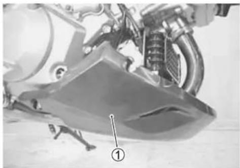
natural_image
Mechanical component with labeled parts, no visible text or symbols

ENGINE IDLE SPEED
Inspect initially at 1 000 km (600 miles, 1 month) and every 6 000 km (4 000 miles, 6 months) thereafter.
NOTE:
Make this adjustment when the engine is hot.
- Start up the engine and set its idle speed to the specified range by turning the throttle stop screw Ⓐ.
DATA Engine idle speed: 1 200 ± 100 r/min
THROTTLE CABLE PLAY
Inspect initially at 1 000 km (600 miles, 1 month) and every 6 000 km (4 000 miles, 6 months) thereafter.
Adjust the throttle cable play Ⓐ with the following three steps.
MINOR ADJUSTMENT
First step:
- Remove cable adjuster covers Ⓑ.
- Loosen the locknut ③ of the throttle returning cable ① and turn in the adjuster ④ fully into the threads.
Second step:
- Loosen the locknut ⑤ of the throttle pulling cable ②.
- Turn the adjuster ⑥ in or out until the throttle cable play ① should be 2.0 - 4.0 mm (0.08 - 0.16 in) at the throttle grip.
- Tighten the locknut ⑤ while holding the adjuster ⑥.
Third step:
- While holding the throttle grip at the fully closed position, slowly turn out the adjuster ④ of the throttle returning cable ① to feel resistance.
- Tighten the locknut ③ while holding the adjuster ④.
DATA Throttle cable play®: 2.0 – 4.0 mm (0.08 – 0.16 in)
WARNING
After the adjustment is completed, check that handle-bar movement does not raise the engine idle speed and that the throttle grip returns smoothly and automatically.
NOTE:
Major adjustment can be made by the throttle body side adjuster.

natural_image
Close-up of a mechanical component with labeled parts (A), showing internal wiring and housing (no readable text or symbols)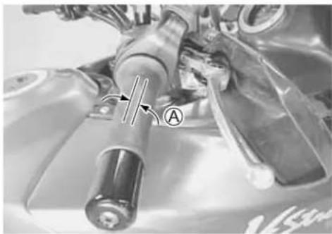
natural_image
Close-up of a mechanical component with labeled parts (A) and directional arrows, no readable text or symbols present.
natural_image
Close-up of a car engine bay with visible components and tool tips (no text or symbols)
MAJOR ADJUSTMENT
- Remove the fuel tank. (4-52)
- Remove the air cleanet box. (4-60)
- Loosen the locknut ① of the throttle returning cable.
- Turn the returning cable adjuster ② to obtain proper cable play.
- Loosen the locknut ③ of the throttle pulling cable.
- Turn the pulling cable adjuster ④ in or out until the throttle cable play Ⓐ should be 2.0 - 4.0 mm (0.08 - 0.16 in) at the throttle grip.
- Tighten the locknut ③ securely while holding the adjuster ④.
DATA Throttle cable play Ⓐ: 2.0 – 4.0 mm (0.08 – 0.16 in)
- While holding the throttle grip at the fully closed position, slowly turn the returning cable adjuster ② to obtain a slack of 1.0 mm (0.04 in).
- Tighten the locknut ① securely.
WARNING
After the adjustment is completed, check that handlebar movement does not raise the engine idle speed and that the throttle grip returns smoothly and automatically.

natural_image
Close-up of a mechanical component with labeled parts (A) and directional arrows, no readable text or symbols beyond labels
THROTTLE VALVE SYNCHRONIZATION
Inspect every 12 000 km (7 500 miles, 12 months).
(4-72)
PAIR (AIR SUPPLY) SYSTEM
Inspect every 12 000 km (7 500 miles, 12 months).
(9-6)
CLUTCH
(CLUTCH HOSE AND CLUTCH FLUID)
Inspect every 6 000 km (4 000 miles, 6 months).
Replace hose every 4 years.
Replace fluid every 2 years.
CLUTCH FLUID LEVEL
- Keep the motorcycle upright and place the handlebars straight.
- Check the clutch fluid level by observing the lower limit line on the clutch fluid reservoir.
- If the level is found to be lower than the lower mark, replenish with BRAKE FLUID that the following specification.

Specification and Classification: DOT 4
WARNING
The clutch system of this motorcycle is filled with a glycol-based brake fluid. Do not use or mix different types of fluid such as silicone-based or petroleum based. Do not use any brake fluid taken from old, used or unsealed containers. Never re-use brake fluid left over from the last servicing or stored for a long periods. Check the clutch hose and hose joints for cracks and oil leakage.

natural_image
Close-up of a motorcycle's front wheel and dashboard (no visible text or symbols)BLEEDING AIR FROM THE CLUTCH FLUID CIRCUIT
The clutch fluid circuit may be purged of air in the following manner.
- Keep the motorcycle upright and place the handlebars straight.
- Fill up the master cylinder reservoir to the upper end of the inspection window. Replace the reservoir cap to prevent entry of dirt.
- Attach a pipe to the bleeder valve and insert the free end of the pipe into a receptacle.
- Squeeze and release the clutch lever several times in rapid succession, and squeeze the lever fully without releasing it. Loosen the bleeder valve by turning it a quarter of a turn so that the fluid runs into the receptacle; this will remove the tension of the clutch lever causing it to touch the handlebar grip. Then, close the valve, pump and squeeze the lever, and open the valve. Repeat this process until the fluid flowing into the receptacle no longer contains air bubbles.
- Close the bleeder valve, and disconnect the pipe. Fill the reservoir with brake fluid to the upper end of the inspection window.
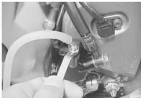
natural_image
Close-up of a hand holding a white plastic hose attached to a mechanical component (no visible text or symbols)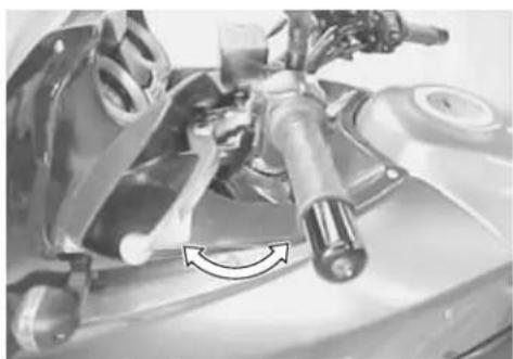
natural_image
Close-up of a motorcycle's front wheel and side-mounted brake lever (no visible text or symbols)
Air bleeder valve: 7.5 N·m (0.75 kg·m, 5.5 lb-ft)
COOLING SYSTEM
Inspect every 6 000 km (4 000 miles, 6 months). Replace engine coolant every 2 years.
ENGINE COOLANT LEVEL CHECK
- Keep the motorcycle upright.
- Check the engine coolant level by observing the full and lower lines on the engine coolant reserve tank.
Ⓐ Full line
⑧ Lower line - If the level is below the lower line, add engine coolant to the full line from the engine coolant reserve tank filler. To remove the filler cap, remove the right fuel tank side cover. (6-4)


natural_image
Close-up of a motorcycle's front wheel and side-mounted lever mechanism (no visible text or symbols)ENGINE COOLANT CHANGE
- Remove the right fuel tank side cover. (6-4)
- Remove the radiator cap ①.
- Drain engine coolant by removing the drain bolts ① and ②.
WARNING
* Do not open the radiator cap when the engine is hot, as you may be injured by escaping hot liquid or vapor.
* Engine coolant may be harmful if swallowed or if it comes in contact with skin or eyes. If engine coolant gets into the eyes or in contact with the skin, flush thoroughly with plenty of water. If swallowed, induce vomiting and call physician immediately!
- Flush the radiator with fresh water if necessary.
- Tighten the water drain bolts Ⓐ and Ⓑ to the specified torque.

Water drain bolt: 13 N·m (1.3 kgf-m, 9.5 lb-ft)
⑧: 5.5 N·m (0.55 kgf·m, 4.0 lb·ft)
- Pour the specified engine coolant up to the radiator inlet.
- Bleed the air from the engine coolant circuit as following procedure.
NOTE:
For engine coolant information, refer to page 5-2.

natural_image
Close-up of a mechanical assembly with a numbered component (1) pointing to a component, no visible text or symbols.
natural_image
Mechanical assembly diagram showing labeled parts A and B (no text or symbols beyond labels)AIR BLEEDING THE ENGINE COOLANT CIRCUIT
- Bleed air from the air bleeder bolt①.
- Tighten the air bleeder bolt ① to the specified torque.

Air bleeder bolt: 13 N·m (1.3 kgf-m, 9.5 lb-ft)
-
Add engine coolant up to the radiator inlet.
• Support the motorcycle upright. -
Lightly tap the thermostat case ② and slowly swing the motor-cycle, right and left, to bleed the air trapped in the case ②.
-
Add engine coolant up to the radiator inlet.
-
Start up the engine and bleed air from the radiator inlet completely.
- Add engine coolant up to the radiator inlet.
-
Repeat the above procedure until bleed no air from the radiator inlet.
-
Close the radiator cap ③ securely.
• After warming up and cooling down the engine several times, add the engine coolant up to the full level of the reserve tank.
CAUTION
Repeat the above procedure several times and make sure that the radiator is filled with engine coolant up to the reserve tank full level.

Engine coolant capacity
Reverse tank side : 250 ml (0.3/0.2 US/lmp qt)
Engine side : 1 950 ml (2.1/1.7 US/lmp qt)

natural_image
Close-up of an automotive engine bay with visible hoses and components (no text or symbols)
natural_image
Close-up of internal mechanical components with hoses and tubing (no visible text or symbols)
natural_image
Close-up of mechanical components including a white car brake system and a white vehicle chassis (no visible text or symbols)
natural_image
Close-up of a mechanical assembly with numbered component (3), no visible text or symbolsRADIATOR HOSES
Check to see the radiator hoses for crack, damage or engine coolant leakage.
If any defects are found, replace the radiator hoses with new ones.
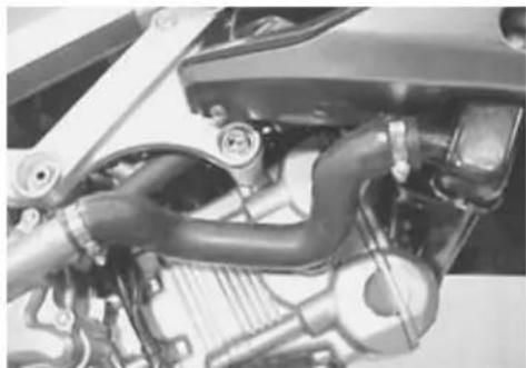
natural_image
Close-up of a mechanical engine component with hoses and springs (no visible text or symbols)DRIVE CHAIN
Inspect initially at 1 000 km (600 miles, 1 month) and every 6 000 km (4 000 miles, 6 months) thereafter. Clean and Lubricate every 1 000 km (600 miles).
Visually check the drive chain for the possible defects listed below. (Support the motorcycle by a jack and a wooden block, turn the rear wheel slowly by hand with the transmission shifted to Neutral.)
* Loose pins * Excessive wear
* Damaged rollers * Improper chain adjustment
* Dry or rusted links * Missing O-ring seals
* Kinked or binding links
If any defects are found, the drive chain must be replaced.

NOTE:
When replacing the drive chain, replace the drive chain and sprockets as a set.
CHECKING
- Remove the axle cotter pin. (For E-03, 28 and 33 models)
- Loosen the axle nut ①.
- Loosen the chain adjuster locknuts ②.
- Tense the drive chain fully by turning both chain adjusters ③.
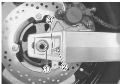

natural_image
Mechanical assembly diagram showing a chain drive and gear mechanism (no text or symbols)- Count out 21 pins (20 pitches) on the chain and measure the distance between the two points. If the distance exceeds the service limit, the chain must be replaced.
DATA
Drive chain 20-pitch length
Service Limit: 319.4 mm (12.6 in)

ADJUSTING
- Loosen or tighten both chain adjusters ① until the chain has 20 - 30 mm (0.8 - 1.2 in) of slack in the middle between engine and rear sprockets. The ends of left and right spacers must be at the same position on the scales A to ensure that the front and rear wheels are correctly aligned.
- Place the motorcycle on its side-stand for accurate adjustment.
- After adjusting the drive chain, tighten the axle nut ② to the specified torque.
- Recheck the drive chain slack after tightening the axle nut ①.
- Tighten both chain adjuster locknuts ③ securely.

Rear axle nut: 100 N·m (10.0 kgf-m, 72.5 lb-ft)
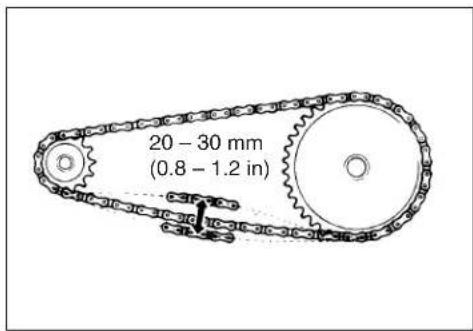


CLEANING AND LUBRICATING
- Wash the chain with kerosene. If the chain tends to rust quickly, the intervals must be shortened.
CAUTION
Do not use trichlene, gasoline or any similar fluids: These fluids have too great a dissolving power for this chain and, what is more important, they can damage the "O"-rings (or seals) confining the grease in the bush to pin clearance. Remember, high durability comes from the presence of grease in that clearance.
• After washing and drying the chain, oil it with a heavy-weight motor oil.
CAUTION
* Do not use any oil sold commercially as “drive chain oil”. Such oil can damage the “O”-rings (or seals).
* The standard drive chain is RK525SMOZ7. SUZUKI recommends that this standard drive chain should be used for the replacement.

natural_image
Close-up of a mechanical assembly with a brake and wheel (no visible text or symbols)BRAKE
(BRAKE)
Inspect initially at 1 000 km (600 miles, 1 month) and every 6 000 km (4 000 miles, 6 months) thereafter.
Inspect every 6 000 km (4 000 miles, 6 months). Replace hoses every 4 years. Replace fluid every 2 years.

natural_image
Close-up of a motorcycle's front wheel and brake lever (no visible text or symbols)- Keep the motorcycle upright and place the handlebars straight.
- Check the brake fluid level by observing the lower limit lines on the front and rear brake fluid reservoirs.
- When the level is below the lower limit line, replenish with brake fluid that meets the following specification.


Specification and Classification: DOT 4
WARNING
The brake system of this motorcycle is filled with a glycol-based brake fluid. Do not use or mix different types of fluid such as silicone-based or petroleum-based. Do not use any brake fluid taken from old, used or unsealed containers. Never re-use brake fluid left over from the last servicing or stored for a long period.
WARNING
Brake fluid, if it leaks, will interfere with safe running and immediately discolor painted surfaces. Check the brake hoses and hose joints for cracks and oil leakage before riding.
- Remove the brake caliper. (Front)
BRAKE PADS
The extent of brake pad wear can be checked by observing the grooved limit Ⓐ on the pad. When the wear exceeds the grooved limit, replace the pads with new ones. (6-57, 67)
CAUTION
Replace the brake pad as a set, otherwise braking performance will be adversely affected.
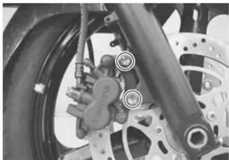
natural_image
Close-up of a motorcycle brake system with visible springs and calipers (no text or symbols)

natural_image
Close-up of a car tire and brake caliper assembly (no visible text or symbols)
natural_image
Mechanical assembly diagram showing a bracket and housing with a magnified inset highlighting component A (no text or symbols present)BRAKE PEDAL HEIGHT
- Loosen the locknut ① and rotate the push rod ② to locate brake pedal 20 – 30 mm (0.8 – 1.2 in) Ⓐ below the top face of the footrest.
- Retighten the locknut ① to secure the push rod ② in the proper position.
DATA Brake pedal height: 20 - 30 mm (0.8 - 1.2 in)
Rear brake master cylinder rod locknut①: 18 N·m (1.8 kgf·m, 13.0 lb·ft)
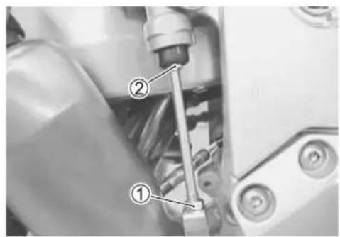
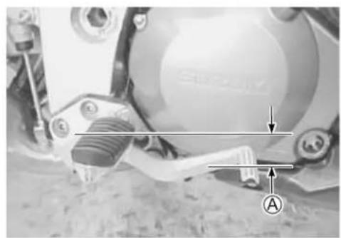
natural_image
Close-up of a mechanical component with labeled parts (A and an arrow), no readable text or symbols present.BRAKE LIGHT SWITCH
Adjust the rear brake light switch so that the brake light will come on just before pressure is felt when the brake pedal is depressed.

natural_image
Close-up of mechanical components with a black arrow pointing to a specific part (no visible text or symbols)AIR BLEEDING THE BRAKE FLUID CIRCUIT
Air trapped in the fluid circuit acts like a cushion to absorb a large proportion of the pressure developed by the master cylinder and thus interferes with the full braking performance of the brake caliper. The presence of air is indicated by “sponginess” of the brake lever and also by lack of braking force. Considering the danger to which such trapped air exposes the machine and rider, it is essential that, after remounting the brake and restoring the brake system to the normal condition, the brake fluid circuit be purged of air in the following manner:
- Fill up the master cylinder reservoir to the "UPPER" line. Place the reservoir cap to prevent entry of dirt.
- Attach a pipe to the air bleeder valve, and insert the free end of the pipe into a receptacle.

Air bleeder valve: 7.5 N·m (0.75 kgf-m, 5.5 lb-ft)
- Front brake: Bleed the air from the air bleeder valve.
- Squeeze and release the brake lever several times in rapid succession and squeeze the lever fully without releasing it. Loosen the bleeder valve by turning it a quarter of a turn so that the brake fluid runs into the receptacle; this will remove the tension of the brake lever causing it to touch the handlebar grip. Then, close the valve, pump and squeeze the lever, and open the valve. Repeat this process until the fluid flowing into the receptacle no longer contains air bubbles.
NOTE:
Replenish the brake fluid in the reservoir as necessary while bleeding the brake system. Make sure that there is always some fluid visible in the reservoir.
- Close the bleeder valve, and disconnect the pipe. Fill the reservoir with brake fluid to the "UPPER" line.
CAUTION
Handle brake fluid with care: the fluid reacts chemically with paint, plastics, rubber materials and so on.
- The only difference between bleeding the front and rear brakes is that the rear master cylinder is actuated by a pedal.

natural_image
Close-up of a hand adjusting automotive brake calipers and components on a vehicle (no visible text or symbols)
natural_image
Close-up of a motorcycle's front wheel and engine components, showing no visible text or symbols
natural_image
Close-up of a hand adjusting a car brake caliper and wheel (no visible text or symbols)
natural_image
Close-up of a mechanical component with a circular arrow and arrowhead, no visible text or symbolsTIRE
Inspect every 6 000 km (4 000 miles, 6 months).
TIRE TREAD CONDITION
Operating the motorcycle with excessively worn tires will decrease riding stability and consequently invite a dangerous situation. It is highly recommended to replace a tire when the remaining depth of tire tread reaches the following specification.

09900-20805: Tire depth gauge

Tire tread depth
Service Limit (FRONT) : 1.6 mm (0.06 in)
(REAR) : 2.0 mm (0.08 in)
TIRE PRESSURE
If the tire pressure is too high or too low, steering will be adversely affected and tire wear increased. Therefore, maintain the correct tire pressure for good roadability or shorter tire life will result. Cold inflation tire pressure is as follows.
| COLD INFLATIONTIRE PRESSURE | SOLO RINDING D | UAL RIDING | ||||
| kPa | kgf/cm2 psi | kPa | kgf/cm2 psi | |||
| FRONT 250 2 | 50 36 | 250 2.50 | 36 | |||
| REAR 250 2.5 | 50 36 | 280 2.80 | 41 | |||
CAUTION
The standard tire fitted on this motorcycle is 110/80 R19M/C (59H) for front and 150/70 R17M/C (69H) for rear. The use of tires other than those specified may cause instability. It is highly recommended to use a SUZUKI Genuine Tire.
TIRE TYPE
BRIDGESTONE (Front : TW101F Rear : TW152F)
STEERING
Inspect initially at 1 000 km (600 miles, 1 month) and every 12 000 km (7 500 miles, 12 months) thereafter.
Steering should be adjusted properly for smooth turning of handlebars and safe running. Overtight steering prevents smooth turning of the handlebars and too loose steering will cause poor stability. Check that there is no play in the steering stem while grasping the lower fork tubes by supporting the machine so that the front wheel is off the ground, with the wheel straight ahead, and pull forward. If play is found, perform steering bearing adjustment as described in page 6-32 of this manual.

natural_image
Diagram of a light bulb with a magnified inset showing the tip and base (no text or symbols)
natural_image
Line drawing of a car wheel with a pressure gauge attached, showing motion lines (no text or symbols)
natural_image
Close-up of a hand adjusting a motorcycle wheel and brake disc (no visible text or symbols)FRONT FORK
Inspect every 12 000 km (7 500 miles, 12 months).
Inspect the front forks for oil leakage, scoring or scratches on the outer surface of the inner tubes. Replace any defective parts, if necessary. (6-15)
REAR SUSPENSION
Inspect every 12 000 km (7 500 miles, 12 months).
Inspect the damper for oil leakage and the spring unit for damage. Check that there is no play in the swing-arm assembly. Replace any defective parts, if necessary. (6-43)
EXHAUST PIPE BOLT
Tighten initially at 1 000 km (600 miles, 1 month) and every 12 000 km (7 500 miles, 12 months) thereafter.
- Tighten the exhaust pipe bolts and muffler mounting bolts to the specified torque.

Muffler mounting bolt /nu#: 23 N·m (2.3 kgf·m, 16.5 lb·ft)
Exhaust pipe bolt ⒷC: 23 N·m (2.3 kgf·m, 16.5 lb·ft)

99000-32050: THREAD LOCK "1342"
EXHAUST GAS SEALER: PERMATEX 1372

| ITEM N·m kgf-m lb-ft | |||
| A B C | 23 2.3 | 1625 | |
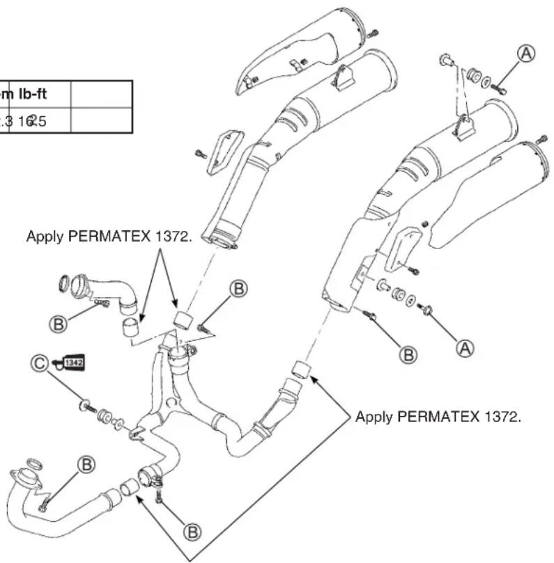
CHASSIS BOLT AND NUT
Tighten initially at 1 000 km (600 miles, 1 month) and every 6 000 km (4 000 miles, 6 months) thereafter.
Check that all chassis bolts and nuts are tightened to their specified torque. (Refer to page 2-28 for the locations of the following nuts and bolts on the motorcycle.)
| ITEM N·m kgf-m lb-ft | |||
| 1 Steering stem head nut 90 9.0 65.0 | |||
| 2 Steering stem locknut 80 8.0 58.0 | |||
| 3 Front fork upper clamp bolt 23 2.3 16.5 | |||
| 4 Front fork lower clamp bolt 23 2.3 16.5 | |||
| 5 Front axle 100 10.0 72.5 | |||
| 6 Front axle pinch bolt 23 2.3 16.5 | |||
| 7 Handlebar holder bolt 23 2.3 16.5 | |||
| 8 Handlebar holder set nut 45 4.5 32.5 | |||
| 9 Front brake master cylinder mounting bolt | 10 | 1.0 | 7.0 |
| 10 Front brake caliper mounting bolt | 39 3.9 28.0 | ||
| 11 Brake hose union bolt | 23 2.3 16.5 | ||
| 12 Clutch master cylinder mounting bolt | 10 | 1.0 | 7.0 |
| 13 Clutch hose union bolt | 23 2.3 16.5 | ||
| 14 Air bleeder valve | 7.5 0.75 5.5 | ||
| 15 Brake disc bolt (Front & Rear) | 23 2.3 16.5 | ||
| 16 Rear brake caliper mounting bolt | 23 2.3 16.5 | ||
| 17 Rear brake master cylinder mounting bolt | 10 | 1.0 | 7.0 |
| 18 Rear brake master cylinder rod locknut | 18 1.8 13.0 | ||
| 19 Front footrest bracket mounting bolt | 26 2.6 19.0 | ||
| 20 Swingarm pivot nut | 100 10.0 72.5 | ||
| 21 Swingarm pivot shaft locknut | 90 | 9.0 | 65.0 |
| 22 Rear shock absorber mounting nut (Upper & Lower) | 50 5.0 36.0 | ||
| 23 Cusion lever mounting nut 78 7.8 56.5 | |||
| 24 Cusion lever rod mounting nut | 78 7.8 56.5 | ||
| 25 Rear axle nut | 100 10.0 72.5 | ||
| 26 Seat rail bolt | 55 5.5 40.0 |


COMPRESSION PRESSURE CHECK
The compression of a cylinder is a good indicator of its internal condition.
The decision to overhaul the cylinder is often based on the results of a compression test. Periodic maintenance records kept at your dealership should include compression readings for each maintenance service.
COMPRESSION PRESSURE SPECIFICATION (Automatic de-comp. actuated)
| Standard Limit | Difference | |
| 1 000 – 1 400 kPa ( 10 - 14 kgf/cm2 \\ 142 - 199 psi ) | 800 kPa ( 8 kgf/cm2 \\ 114 psi ) | 200 kPa ( 2 kgf/cm2 \\ 28 psi ) |
Low compression pressure can indicate any of the following conditions:
* Worn-down piston or piston rings
* Piston rings stuck in grooves
* Poor seating of valves
* Ruptured or otherwise defective cylinder head gasket
Overhaul the engine in the following cases:
* Compression pressure in one of the cylinders is less than 800 kPa (8 kgf/cm², 114 psi).
* Difference in compression pressure between two cylinders is more than 200 kPa (2 kgf/cm², 28 psi).
* All compression pressure are below 1 000 kPa (10 kgf/cm², 142 psi) even when they measure more than 800 kPa (8 kgf/cm², 114 psi).
COMPRESSION TEST PROCEDURE
NOTE:
* Before testing the engine for compression pressure, make sure that the cylinder head bolts are tightened to the specified torque values and valves are properly adjusted.
* Have the engine warmed up by idling before testing.
* Be sure that the battery used is in fully-charged condition.
Remove the parts concerned and test the compression pressure in the following manner.
- Remove the radiator. (5-4)
- Remove all the spark plugs. (2-5)
- Fit the compression gauge in one of the plug holes, while taking care of the tight connection.
- Keep the throttle grip in full-open position.
- While cranking the engine a few seconds with the starter, and record the maximum gauge reading as the compression of that cylinder.
- Repeat this procedure with an other cylinder.

09915-64510: Compression gauge
09913-10750: Adaptor
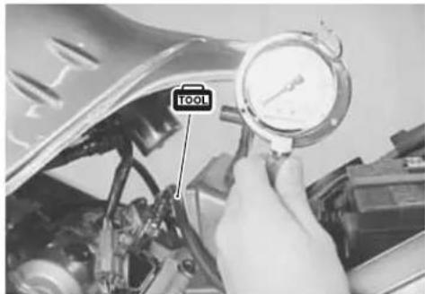

natural_image
Close-up of a hand holding a pressure gauge with attached components (no visible text or symbols)
natural_image
Close-up of a hand adjusting a car's steering wheel (no visible text or symbols)OIL PRESSURE CHECK
Check periodically the oil pressure in the engine to judge roughly the condition of the moving parts.
OIL PRESSURE SPECIFICATION
Above 400 kPa (4.0 kgf/cm², 57 psi)
Below 700 kPa (7.0 kgf/cm², 100 psi)
at 3 000 r/min., Oil temp. at 60°C (140°F)
If the oil pressure is lower or higher than the specification, the following causes may be considered.
LOW OIL PRESSURE
* Clogged oil filter
* Oil leakage from the oil passage way
* Damaged O-ring
* Defective oil pump
* Combination of the above items
HIGH OIL PRESSURE
* Used of high viscosity engine oil
* Clogged oil passage way
* Combination of the above items

natural_image
Mechanical assembly diagram showing motor components and a numbered component (no text or symbols present)OIL PRESSURE TEST PROCEDURE
Start the engine and check if the oil pressure indicator light is turned on. If it keeps on lighting, check the oil pressure indicator light circuit. If it is in good condition, check the oil pressure in the following manner.
- Remove the engine under cover ①.
- Remove the main oil gallery plug ②.
• Install the oil pressure gauge with attachment in the position shown in the figure.
• Warm up the engine as follows:
Summer 10 min. at 2 000 r/min.
Winter 20 min. at 2 000 r/min. - After warming up, increase the engine speed to 3 000 r/min. (with the engine tachometer), and read the oil pressure gauge.

natural_image
Close-up mechanical assembly showing internal components and a numbered annotation (no readable text or symbols)
natural_image
Close-up of a motorcycle's internal engine and wheel assembly, showing hoses and components (no visible text or symbols)
09915-72410: Oil pressure gauge attachment
09915-74521: Oil pressure gauge hose
09915-74532: Oil pressure gauge attachment
09915-77331: Meter (for high pressure)

Oil gallery plug [M 8]: 18 N·m (1.8 kgf-m, 13.0 lb-ft)
ENGINE
CONTENTS
ENGINE COMPONENTS REMOVABLE WITH ENGINE IN PLACE ...3- 2
ENGINE REMOVAL AND INSTALLATION ....3- 3
ENGINE REMOVAL 3-3
ENGINE INSTALLATION 3-12
ENGINE DISASSEMBLY 3-19
ENGINE TOP SIDE 3-19
ENGINE BOTTOM SIDE 3-25
ENGINE COMPONENTS INSPECTION AND SERVICING ....3-34
CYLINDER HEAD COVER 3-34
CAMSHAFT/CYLINDER HEAD 3-35
CYLINDER/PISTON INSPECTION 3-47
CONROD/CRANKSHAFT 3-50
CLUTCH 3-54
TRANSMISSION 3-56
GEARSHIFT FORK 3-62
PRIMARY DRIVE GEAR 3-63
STARTER TORQUE LIMITER 3-64
STARTER CLUTCH 3-65
GEARSHIFT 3-66
CRANKCASE 3-66
CRANKCASE-CRANKSHAFT BEARING ....3-71
GENERATOR COVER 3-77
CLUTCH COVER 3-77
GEARSHIFT COVER 3-77
ENGINE REASSEMBLY 3-78
ENGINE BOTTOM SIDE 3-78
ENGINE TOP SIDE 3-92
ENGINE COMPONENTS REMOVABLE WITH ENGINE IN PLACE
The parts listed below can be removed and reinstalled without removing the engine from the frame. Refer to the page listed in this section for removal and reinstallation instructions.
ENGINE LEFT SIDE
| PARTS REMOVAL INSTALLATION | ||
| Generator rotor 3-31 3-82Gearshift 3-31 3-80 |
ENGINE RIGHT SIDE
| PARTS REMOVAL INSTALLATION | ||
| Clutch cover 3-26 3-89 | ||
| Clutch 3-26 3-86 | ||
| Oil pump driven gear 3-29 3-86 | ||
| Primary drive gear 3-30 3-83 | ||
| Cam drive idle gear/sprocket 3-29 3-84 | ||
| Gear position switch 3-28 3-85 | ||
| Oil sump filter 3-29 3-85 | ||
| Oil pressure switch | 3-67 3-67 | |
| Oil jet | 3-67 | 3-68, 94 |
ENGINE CENTER
| PARTS REMOVAL INSTALLATION | ||
| Cylinder head cover | 3-19, 22 | 3-111 |
| Camshaft | 3-20, 23 | 3-105 |
| Cylinder head (Front) | 3-20 3-95 | |
| Cylinder (Front) | 3-21 3-94 | |
| Piston (Front) | 3-22 3-92 | |
| Cam chain tension adjuster | 3-20, 23 | 3-101, 104 |
| Oil filter | 3-25 3-92 | |
| Starter motor | 3-21 | 3-112 |
ENGINE REMOVAL AND INSTALLATION
ENGINE REMOVAL
Before taking the engine out of the frame, wash the engine using a steam cleaner. Engine removal is sequentially explained in the following steps. Reinstall the engine by reversing the removal procedure.
- Drain engine oil. (2-12)
- Drain engine coolant. (2-17)
- Remove the seat. (6-4)
- Disconnect the battery lead wire.
- Remove the engine under cover ①.
- Remove the fuel tank side covers ②, cowlings ③ and inner cowling. (6-6)
- Remove the radiator and water hoses.
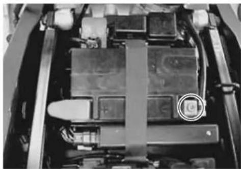
natural_image
Interior view of a car showing battery compartments and wiring (no visible text or symbols)
natural_image
Close-up of a motorcycle's internal engine and drivetrain components (no visible text or symbols)

natural_image
Close-up mechanical assembly showing hoses and components with directional arrows (no visible text or symbols)- Remove the fuel tank ①.
- Remove the air cleaner.
- Remove the throttle body.
- Remove the spark plug caps.
- Remove the camshaft position sensor lead wire coupler ①.
- Disconnect the gear position switch lead wire coupler ②.

natural_image
Close-up of a metallic mechanical component with labeled part (1), no visible text or symbols beyond the label
natural_image
Close-up of a car engine compartment with visible structural components (no text or symbols)
natural_image
Close-up of an engine cylinder assembly with visible internal components and wiring (no text or symbols)
natural_image
Mechanical assembly diagram showing two views of a vehicle's internal components with no visible text or symbols
natural_image
Close-up of a mechanical component with no visible text or symbols- Disconnect the generator lead wire coupler ① and signal generator lead wire coupler ② after removing the screw A.
- Remove the gearshift lever link.
- Remove the engine coolant temperature sensor lead wire coupler ③.
- Bind the clutch lever with a rubber band to prevent the clutch release cylinder piston from coming out.
- Remove the clutch release cylinder ④.

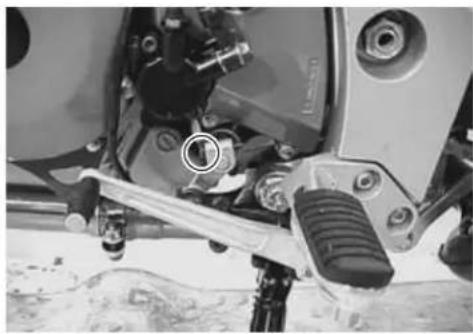
natural_image
Close-up of a mechanical assembly with no visible text or symbols
natural_image
Close-up mechanical assembly showing internal components and a numbered label (③), no readable text or symbols present.
natural_image
Close-up of a motorcycle's front wheel and suspension components (no visible text or symbols)
natural_image
Mechanical assembly diagram showing components with numbered annotations (no readable text or symbols)- Remove the push rod ①.
- Remove the engine sprocket cover ②.
- Remove the speed sensor ③.
- Remove the engine sprocket nut and washer while depressing the brake pedal.
- Remove the cotter pin. (For E-03, 28, 33)
- Loosen the rear axle nut ④.
- Loosen the chain adjusters ⑤ by loosening the lock nuts ⑥.
- Remove the engine sprocket ⑦.

natural_image
Mechanical assembly diagram showing components with numbered annotations (no readable text or symbols)
natural_image
Mechanical assembly diagram showing a gear-like component with a numbered annotation (3), no readable text or symbols present.
natural_image
Close-up of a mechanical assembly showing gears and shafts with an arrow pointing to a central component (no visible text or symbols)

natural_image
Mechanical assembly diagram showing internal components with no visible text or symbols- Disconnect the engine ground lead wire ①.
- Disconnect the O2 sensor lead wire couplers ②, ③.
- Remove the mufflers. (L & R)
- Loosen the front exhaust pipe mounting bolts.

- Remove the front exhaust pipe.
- Remove the mud guard ①.
- Remove the rear exhaust pipe.
- Remove the right footrest bracket and brake pedal.
- Remove the oil cooler ②.
- Disconnect the starter motor lead wire ③ and oil pressure switch lead wire ④.

- Support the engine with an engine jack.
- Remove the engine mounting nut ① and bolt. - Loosen the engine mounting thrust adjuster lock nut with the special tool.

09940-14990: Engine mounting thrust adjuster socket wrench
- Loosen the engine mounting thrust adjuster.

09940-14990: Engine mounting thrust adjuster socket wrench
- After removing the pinch bolt ②, remove the engine mounting bolt ③.
- Remove the engine mounting bolt ④. - Remove the engine mounting bracket ⑤.

natural_image
Close-up of a mechanical assembly with gears and components (no visible text or symbols)
natural_image
Close-up of a car engine component showing internal parts and a tool labeled 'TOOL' (no text or symbols beyond labels)
natural_image
Close-up of a car suspension system with a tool labeled 'TOOL' pointing to a component (no readable text or symbols beyond the label)

- Remove the ignition coil lead wires.
- Remove the engine mounting nut ①.
- Loosen the engine mounting thrust adjuster lock nut.

09940-14990: Engine mounting thrust adjuster socket wrench
- Loosen the engine mounting thrust adjuster ②.
- Loosen the pinch bolt ③.

natural_image
Close-up of mechanical components with two circular features, no visible text or symbols
natural_image
Close-up mechanical assembly showing a component with numbered annotation (1), no readable text or symbols present.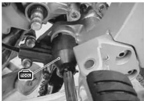
natural_image
Close-up of mechanical components with a tool labeled 'TOOL' pointing to a specific part (no readable text or symbols beyond the label)
natural_image
Close-up mechanical assembly showing a component with numbered annotation (no readable text or symbols)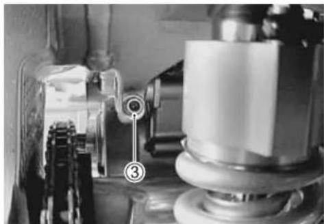
natural_image
Close-up of mechanical components with numbered annotations (③ and ④) indicating parts of a device or assembly (no readable text or symbols beyond labels)- Gradually lower the engine assembly by removing the bolt ①, ②.
CAUTION
Be careful not to damage the frame and engine when removing the engine from the frame.

natural_image
Close-up of mechanical components with numbered annotations (1 and 2), no readable text or symbols present.ENGINE INSTALLATION
Remount the engine in the reverse order of engine removal.
Pay attention to the following points:
NOTE:
* The engine mounting nuts are self-locking.
* Once the nut has been removed, it is no longer of any use. Be sure to use new nuts, and then tighten them to the specified torque.

| ITEM N | m kgf-m | lb-ft | |
| A B D E | 55 5.5 | 40.0 | |
| J K L | 23 2.3 | 16.53 | 16 |
| F H | 12 1.2 | 8.5 | 5 |
| G I | 45 4.5 | 32.5 | |
| C | 75 7.5 | 54.0 |
- Before installing the engine assembly, install the spacer Ⓐ, collar Ⓑ and engine thrust adjuster Ⓒ, Ⓓ.

• Install the collar Ⓑ onto the crankcase properly as shown.
- Apply THREAD LOCK "1342" to the engine mounting bracket bolts.
- Tighten the bolts to the specified torque.

Engine mounting bracket bolt:
23 N·m (2.3 kgf-m, 16.5 lb-ft)

342
99000-32050: THREAD LOCK "1342"

natural_image
Technical line drawing of a mechanical component with threaded parts and a labeled section B (no text or symbols beyond label)
- Put the drive chain on the driveshaft.
- Gradually raise the engine assembly and align all the bolt holes.
• Install the engine mounting bolts and bracket bolts, and tighten them temporarily. - Tighten the engine mounting thrust adjuster and its lock nut to the specified torque with the special tool.
Engine mounting thrust adjuster: 12 N·m (1.2 kgf·m, 8.5 lb·ft) Engine mounting thrust adjuster lock nut:
45 N·m (4.5 kgf-m, 32.5 lb-ft)

09940-14990: Engine mounting thrust adjuster socket wrench
- After tightening the engine mounting bolt Ⓐ, tighten the pinch bolt Ⓑ.
Engine mounting bolt A: 55 N·m (5.5 kgf·m, 40.0 lb·ft) Engine mounting pinch bolt B:
23 N·m (2.3 kgf-m, 6.5 lb-ft)
- Tighten the engine mounting bolt to the specified torque.
Engine mounting bolt©: 55 N·m (5.5 kgf-m, 40.0 lb-ft)

natural_image
Close-up of mechanical gear and chain components (no visible text or symbols)
natural_image
Mechanical assembly diagram showing two views of a mechanical component with a tool labeled 'TOOL' (no readable text or symbols beyond label)

natural_image
Close-up of mechanical components with labeled parts A and B, no readable text or symbols present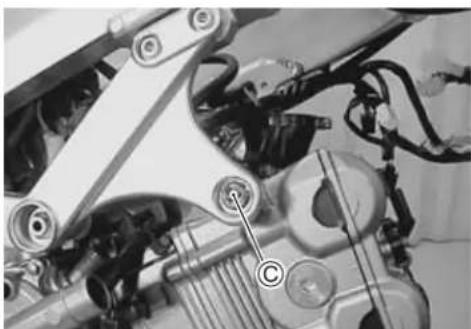
natural_image
Mechanical assembly diagram showing components like gears and linkages (no visible text or labels)- Tighten the engine mounting nut Ⓐ, Ⓑ to the specified torque.
Engine mounting nut: 75 N·m (7.5 kgf·m, 54.0 lb·ft) Engine mounting nut Ⓐ: 55 N·m (5.5 kgf·m, 40.0 lb·ft)
- After tightening the bolt Ⓐ, tighten the pinch bolt Ⓓ to the specified torque.
Engine mounting bolt: 55 N·m (5.5 kgf-m, 40.0 lb-ft) Engine mounting pinch bolt: 23 N·m (2.3 kgf-m, 16.5 lb-ft)
• Install the washers and tighten the union bolt to the specified torque.
Oil hose union bolt: 23 N·m (2.3 kgf-m, 16.5 lb-ft)
• Install the new gaskets.
• Install the exhaust pipes and mufflers.
NOTE:
Apply THREAD LOCK "1342" to the bolt Ⓔ.

99000-32050: THREAD LOCK "1342"


- Adjust the brake pedal height.
DATA Brake pedal height®
Standard: 20 - 30 mm (0.8 - 1.2 in)
• Install the gearshift arm as shown.
DATA Gearshift arm angle®: Approx. 60°

natural_image
Mechanical assembly diagram showing a rotating component with labeled point A (no readable text or symbols)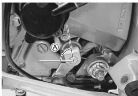
natural_image
Close-up of a mechanical component with labeled parts (A), no visible text or symbols beyond the label.- Adjust the gearshift lever as shown.

Gearshift lever height®
Standard: 20 - 30 mm (0.8 - 1.2 in)
• Install the engine sprocket.
- Apply THREAD LOCK SUPER "1303" to the engine sprocket nut and tighten it to the specified torque while depressing the brake pedal.

Engine sprocket nut: 115 N·m (11.5 kgf-m, 83.0 lb-ft)

99000-32030: THREAD LOCK SUPPER "1303"
- Tighten the speed sensor rotor bolt to the specified torque.

Speed sensor rotor bolt: 23 N·m (2.3 kgf·m, 16.5 lb·ft)
- Apply SUZUKI SUPER GREASE "A" to the push rod ① and install it.
• Install the clutch release cylinder.

99000-25030: SUZUKI SUPER GREASE "A" (USA) 99000-25010: SUZUKI SUPER GREASE "A" (Others)
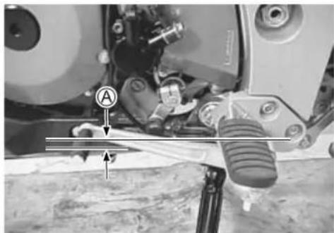
natural_image
Mechanical assembly diagram showing a component with labeled parts and directional arrows (no readable text or symbols)
natural_image
Close-up of a mechanical gear assembly with chain links and central hub (no visible text or symbols)
natural_image
Close-up of a mechanical gear assembly with no visible text or symbols
natural_image
Close-up of a mechanical assembly with gears and housing (no visible text or symbols)
- After installing the engine, route the wire harness, cables and hoses properly. (8-14)
- Adjust the following items.
* Engine oil 2-12
* Engine coolant 2-17
* Engine idle speed 2-14
* Throttle cable play 2-14
DATA
Engine oil capacity
Oil change: 2.7 L (2.9/2.4 US/lmp qt)
Oil and filter change: 2.9 L (3.1/2.6 US/Imp qt)
Engine overhaul: 3.3 L (3.5/2.9 US/Imp qt)
ENGINE DISASSEMBLY ENGINE TOP SIDE
- Remove the thermostat.
- Remove the valve timing inspection plug ① and generator cover plug ②.
FRONT CYLINDER HEAD COVER
- Remove the front cylinder head cover ①.
- Turn the crankshaft to bring the "F | T" line on generator rotor to the index mark of the valve inspection hole and also to bring the cams to the position as shown.
NOTE:
At the above condition, the No.1 (Front) cylinder is at TDC of compression stroke and also the engraved lines Ⓐ on the camshafts are parallel with the mating surface of the cylinder head cover.

natural_image
Close-up of mechanical components with no visible text or symbols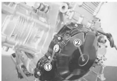

natural_image
Close-up of mechanical components with no visible text or symbols

FRONT CYLINDER CAMSHAFT
- Remove the camshaft journal holders.
CAUTION
Be sure to loosen the camshaft journal holder bolts evenly by shifting the wrench diagonally.
- Remove the camshafts.
NOTE:
Do not drop the dowel pins into the crankcase.
FRONT CAM CHAIN TENSION ADJUSTER
- After loosing the spring holder bolt ①, remove the cam chain tension adjuster.
FRONT CYLINDER HEAD
- Remove the cam drive idle gear/sprocket ① by removing its shaft with the copper washer and the thrust washer ②.
NOTE:
Do not the drop the thrust washer ② into the crankcase.
- Remove the cylinder head bolts and cam chain tensioner mounting bolt.
- Remove the cam chain tensioner.
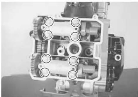
natural_image
Cross-sectional view of a mechanical transmission system with visible gears and shafts (no text or labels)
natural_image
Cross-sectional view of a mechanical assembly showing internal gears and housing (no visible text or labels)
natural_image
Close-up of an engine component with numbered annotations (1 and 2) pointing to specific parts, no readable text or symbols present.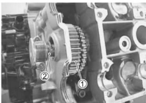
natural_image
Close-up of mechanical gears and shafts in a vehicle assembly (no visible text or symbols)
natural_image
Close-up of a mechanical assembly showing internal components and housing (no visible text or symbols)STARTER MOTOR
- Remove the starter motor.
- Remove the cylinder head nut.
- Loosen the cylinder nuts.
- Remove the oil cooler mounting bracket ①.
- Remove the cylinder head bolts.
- Remove the cylinder head.
NOTE:
* When loosening the cylinder head bolts, loosen each bolt little by little diagonally.
* To identify each cylinder head, mark the cylinder as the front and rear, cylinder head uses the same part.
FRONT CYLINDER
- Remove the cylinder.
NOTE:
Firmly grip the cylinder at both ends, and lift it straight up. If the cylinder does not come off, lightly tap on the finless portions of the cylinder with a plastic mallet to make the gasketed joint loose.
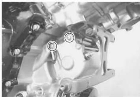
natural_image
Close-up mechanical assembly showing internal components and mounting holes (no visible text or symbols)
natural_image
Close-up of internal mechanical components with no visible text or symbols
natural_image
Mechanical assembly diagram showing internal components with no visible text or symbols
natural_image
Cross-sectional view of a mechanical assembly with internal components and highlighted circular features (no text or symbols)
natural_image
Close-up of a mechanical assembly with circular annotations highlighting specific components (no visible text or symbols)- Remove the cylinder base gasket and dowel pins.
FRONT PISTON
- Place a clean rag over the cylinder base so as not to drop the piston pin circlip into the crankcase.
- Remove the piston pin circlip.
- Remove the piston by driving out the piston pin.
NOTE:
Scribe the cylinder number on the head of the piston.
REAR CYLINDER HEAD COVER
- Remove the rear cylinder head cover ①.
- Turn the crankshaft to bring the "F | T" line mark on generator rotor to the index mark of the valve inspection hole and also to bring the cams to the position as shown.
NOTE:
At the above condition, the rear cylinder is at ATDC 90° on expansion stroke and also the engraved lines Ⓐ on the camshafts are parallel with the mating surface of the cylinder head cover.

natural_image
Close-up of mechanical components with circular annotations highlighting specific parts (no readable text or symbols)
natural_image
Close-up of a mechanical component with a metallic ring and a cylindrical shaft, no visible text or symbols.
natural_image
Close-up of a mechanical component with labeled parts (no visible text or symbols)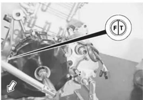

CAUTION
Pull the front cam chain upward, or the chain will be caught between the crankcase and cam drive idle gear/sprocket when turning the crankshaft.
REAR CYLINDER CAMSHAFT
- Remove the two camshaft journal holders.
CAUTION
Be sure to loosen the camshaft journal holder bolts evenly by shifting the wrench diagonally.
- Remove the camshafts.
NOTE:
Do not drop the dowel pins into the crankcase.
REAR CAM CHAIN TENSION ADJUSTER
- After loosing the spring holder bolt ①, remove the cam chain tension adjuster.
REAR CYLINDER HEAD
- Remove the cam drive idle gear/sprocket ① by removing its shaft, the copper washer and the thrust washer ②.
NOTE:
Do not drop the thrust washer ② into the crankcase.

natural_image
Close-up of mechanical components including a valve and housing (no visible text or symbols)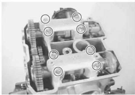
natural_image
Cross-sectional view of a mechanical engine showing internal components and gear (no visible text or labels)
natural_image
Close-up of a mechanical assembly showing internal gears and shafts (no visible text or symbols)
natural_image
Close-up of mechanical components with numbered annotations (1 and two circles), no readable text or symbols present.
natural_image
Close-up of mechanical gear assembly with numbered annotations (1 and 2), no readable text or symbols present.- Remove the cylinder head bolts and cam chain tensioner mounting bolt.
- Remove the cam chain tensioner.
- Remove the cylinder head nuts ①.
- Remove the cylinder head nut ②.
- Loosen the cylinder nuts ③.
- Remove the cylinder head bolts.
- Remove the cylinder head.
NOTE:
* When loosening the cylinder head bolts, loosen each bolt little by little diagonally.
* To identify each cylinder head, mark the cylinder as the Front and Rear.
REAR CYLINDER
- Remove the rear cylinder.
NOTE:
Firmly grip the cylinder at both ends, and lift it straight up. If the cylinder does not come off, lightly tap on the finless portions of the cylinder with a plastic mallet to make the gasketed joint loose.

natural_image
Close-up of mechanical components with circular annotations pointing to specific parts (no visible text or symbols)
natural_image
Close-up of a mechanical component with two circular annotations pointing to features, no visible text or symbols.
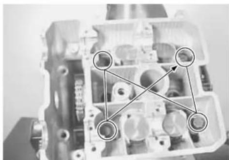
natural_image
Close-up of a mechanical assembly with internal components and a highlighted triangular mesh pattern (no text or symbols)
natural_image
Close-up of a mechanical assembly with gears and shafts, no visible text or symbols- Remove the cylinder base gasket and dowel pins.
REAR PISTON
- Place a clean rag over the cylinder base so as not to drop the piston pin circlip into the crankcase.
- Remove the piston pin circlip.
- Remove the piston by driving out the piston pin.
NOTE:
Scribe the cylinder number on the head of the piston.
ENGINE BOTTOM SIDE
OIL FILTER
- Remove the oil filter with the special tool.

09915-40610: Oil filter wrench
- Remove the generator cover.
- Remove the starter torque limiter ① and starter idle gear ②.
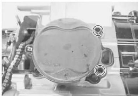
natural_image
Close-up of a mechanical component with circular features and mounting brackets (no visible text or symbols)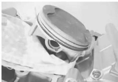
natural_image
Close-up of a mechanical piston assembly with visible internal components (no text or symbols)
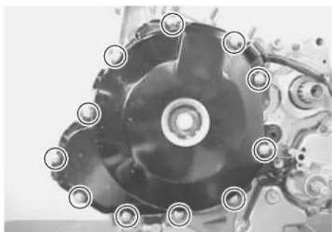
natural_image
Close-up of a mechanical component with multiple circular features and central hub (no visible text or symbols)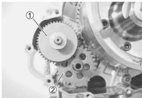
natural_image
Mechanical gear assembly diagram showing two labeled components (① and ②), no readable text or symbols present.- Remove the bushings ① from the crankcase and generator cover.

natural_image
Close-up of mechanical components with numbered annotations (1) showing internal parts and mounting holes (no readable text or symbols)CLUTCH COVER
- Remove the water pump case. WATER PUMP DISASSEMBLY 5-13

natural_image
Close-up of a mechanical component with circular annotations highlighting specific parts (no readable text or symbols)CLUTCH
- Remove the clutch cover.
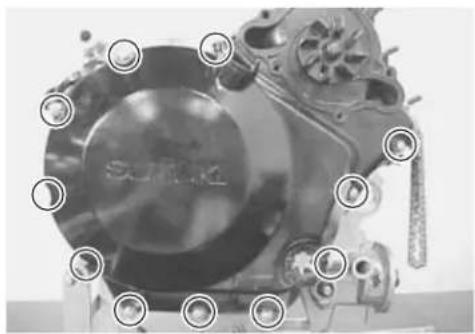
natural_image
Close-up of a mechanical engine component with circular features and no visible text or symbols- Hold the generator rotor with the special tool.

09930-44541: Rotor holder

natural_image
Close-up of a mechanical assembly with a tool labeled 'TOOL' pointing to a component (no readable text or symbols beyond the label)- While holding the generator rotor, remove the clutch spring set bolts and springs diagonally.
- Remove the pressure plate ①.

natural_image
Close-up of an internal combustion engine showing gears and shafts (no text or symbols visible)- Remove the clutch push piece, bearing and thrust washer.
- Remove the clutch push rod ①.
- Remove the clutch drive and driven plates.
- Remove the wave washer ② and wave washer seat ③.
- Unlock the clutch sleeve hub nut.
- While holding the clutch sleeve hub with the special tool, remove the clutch sleeve hub nut.

09920-53740: Clutch sleeve hub holder
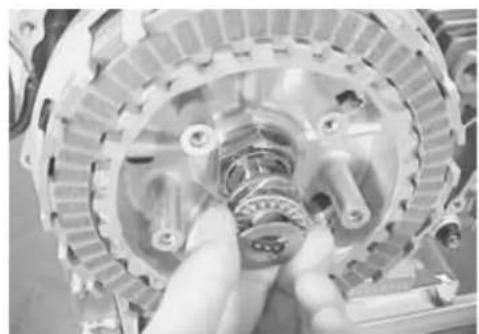
natural_image
Close-up of a mechanical assembly showing a hand adjusting a gear mechanism (no visible text or symbols)
natural_image
Close-up of a mechanical assembly with visible gears and housing (no text or symbols)
natural_image
Close-up of a mechanical assembly with numbered annotations pointing to components (no readable text or symbols)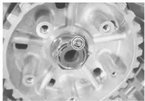
natural_image
Close-up of a mechanical gear assembly with central hub and multiple teeth (no visible text or symbols)
natural_image
Mechanical gear assembly with a tool labeled 'TOOL' (no readable text or symbols beyond label)- Remove the washer ① and ②.
-
Remove the clutch sleeve hub ③.
-
Remove the thrust washer ④.
- Remove the primary driven gear assembly.
- Remove the needle roller bearing, spacer and thrust washer.
GEAR POSITION SWITCH
- Remove the gear position switch.
- Remove the gear position switch contacts ① and springs ②.


natural_image
Close-up of a mechanical assembly with gears and housing (no visible text or symbols)
natural_image
Close-up of mechanical components including gears and housing (no visible text or symbols)
natural_image
Close-up of mechanical components with circular annotations highlighting specific parts (no readable text or symbols)
OIL SUMP FILTER
- Remove the oil sump filter.
OIL PUMP
- Remove the oil pump driven gear ① by removing the snap ring.

09900-06107: Snap ring pliers
- Remove the pin ② and washer ③.
NOTE:
Do not drop the snap ring, pin and washer into the crankcase.
- Hold the generator rotor with the special tool.

09930-44541: Rotor holder
CAM DRIVE IDLE GEAR/SPROCKET
- While holding the generator rotor, remove the cam drive idle gear/sprocket nut.

natural_image
Close-up of mechanical components including gears and a battery casing (no visible text or symbols)
natural_image
Mechanical gear assembly with labeled component (1), no visible text or symbols

natural_image
Close-up of a mechanical assembly with a tool labeled 'TOOL' pointing to a component (no readable text or symbols beyond the label)
natural_image
Close-up of a mechanical gear assembly with visible teeth and shafts (no text or symbols)- Insert a suitable bar into the holes of primary drive gears to align the teeth of scissors gears.
- Remove the cam drive idle gear/sprocket and cam chain.
- Remove the key ①.
PRIMARY DRIVE GEAR
- Hold the generator rotor with the special tool.

09930-44541: Rotor holder
- While holding the generator rotor, remove the primary drive gear nut.
CAUTION
This bolt has left-hand thread. Turning it counterclockwise may cause damage.
- Remove the washer ①.
- Remove the primary drive gear assembly ②.

natural_image
Close-up of mechanical gears and shafts in a vehicle assembly (no visible text or symbols)
natural_image
Close-up of a mechanical gear assembly with a threaded shaft and adjustment knob (no visible text or symbols)
natural_image
Close-up of a mechanical assembly with a labeled tool (no readable text or symbols beyond the label)
natural_image
Close-up mechanical assembly showing gears and shafts in a vehicle (no visible text or symbols)
natural_image
Mechanical gear assembly with numbered components (1, 2), no visible text or symbols- Remove the key ① and thrust washer ②.
GENENRATOR ROTOR
- While holding the generator rotor with the special tool, remove its bolt.

09930-44541: Rotor holder
• Install the special tool to the boss.
- Remove the generator rotor by turning the special tool while holding the generator rotor with the special tool.

09930-30450: Generator rotor remover bolt
- Remove the key ① and starter driven gear ②.
GEARSHIFT
- Remove the gearshift cover.

natural_image
Close-up of a mechanical component with numbered annotations (1 and 2), no readable text or symbols present.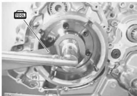
natural_image
Close-up of a mechanical assembly with a tool labeled 'TOOL' pointing to a central component (no readable text or symbols beyond the label)

natural_image
Close-up of a mechanical gear assembly with labeled parts (① and ②), no readable text or symbols beyond labels
natural_image
Close-up of a mechanical component with bolt holes and mounting brackets (no visible text or symbols)- Draw out the gearshift shaft ①.
- Remove the gearshift cam plate ②.
- Remove the gearshift cam stopper ③.
- Remove the engine sprocket spacer ④.
- Remove the cam drive idle gear shaft ⑤.
- Remove the crankcase bolts.

natural_image
Close-up mechanical assembly showing internal components and a numbered label (1) pointing to a specific part (no readable text or symbols)
natural_image
Close-up of a mechanical assembly with numbered components (no visible text or symbols)
natural_image
Close-up mechanical assembly showing a central shaft and housing with mounting holes (no visible text or symbols)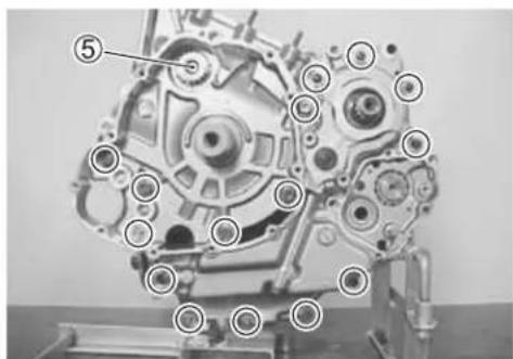
natural_image
Mechanical engine component with numbered parts (no visible text or symbols)
natural_image
Detailed mechanical assembly diagram showing internal gears and shafts (no text or labels visible)- Separator the crankcase into 2 parts, right and left with the crankcase separating tool.

09920-13120: Crankcase separating tool
NOTE:
* Fit the crankcase separating tool, so that the tool arms are in parallel with the side of crankcase.
* The crankshaft and transmission components should remain in the left crankcase half.
* When separating the crankcase, tap the end of the counter-shaft with a plastic hammer.
- Remove the gearshift fork shafts, gearshift forks and gearshift cam.

natural_image
3D mechanical assembly diagram showing internal components and a labeled tool (no text or symbols beyond the label)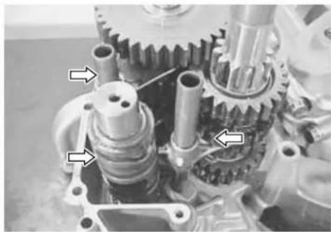
natural_image
Close-up of mechanical gear assembly with no visible text or symbols- Remove the countershaft and driveshaft.

natural_image
Close-up mechanical assembly showing gears and shafts in a mechanical component (no visible text or symbols)- Remove the crankshaft.
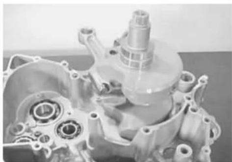
natural_image
Close-up of a mechanical assembly with gears and housing (no visible text or symbols)ENGINE COMPONENTS INSPECTION AND SERVICING CYLINDER HEAD COVER
DISASSEMBLY
CAUTION
Be sure to identify each removed part as to its location, and lay the parts out in groups designated as "No.1", "No.2" "Exhaust", "Intake", so that each will be restored to the original location during assembly.
- Remove the camshaft position sensor ①.
- Remove the PAIR reed valve cover ②.
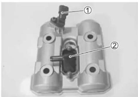
INSPECTION
- Inspect the PAIR reed valve for the carbon deposit.
- If the carbon deposit is found in the reed valve, replace it with a new one.

natural_image
Black rectangular electronic device with two small buttons on top, isolated on white background (no text or symbols)REASSEMBLY
- Apply SUZUKI SUPER GREASE "A" to the O-ring and install it.

99000-25030: SUZUKI SUPER GREASE "A" (USA) 99000-25010: SUZUKI SUPER GREASE "A" (Others)

natural_image
Close-up of a mechanical component with a hand adjusting a small component (no visible text or symbols)- Apply THREAD LOCK "1342" to the thread and install the PAIR reed valve cover.

99000-32050: THREAD LOCK "1342"
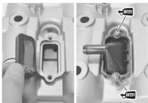
natural_image
Close-up of mechanical components with no visible text or symbolsCAMSHAFT/CYLINDER HEAD
CAUTION
Be sure to identify each removed part as to its location, and lay the parts out in groups designated as "No.1", "No.2", "Exhaust", "Intake", so that each will be restored to the original location during assembly.
CAMSHAFT
All camshafts should be checked for runout and also for wear of cams and journals if the engine has been noted as giving abnormal noise, vibration or lack power output. Any of these conditions may be caused by camshafts worn down or distorted to the service limit.
The camshafts can be identified by the engraved letter.
① No.1 (Front) intake camshaft ("INF" and "I": Intake)
② No.1 (Front) exhaust camshaft ("EXF" and "E": Exhaust)
③ No.2 (Rear) intake camshaft ("INR" and "I": Intake)
④ No.2 (Rear) exhaust camshaft ("EXR" and "E": Exhaust)
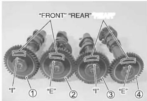

CAM WEAR
Worn-down cams are often the cause of mistimed valve operation resulting in reduced power output.
The limit of cam wear is specified for both intake and exhaust cams in terms of cam height Ⓗ, which is to be measured with a micrometer. Replace camshaft if it wears worn down to the limit.

Cam height®
Service Limit (IN) : 35.98 mm (1.417 in)
(EX): 35.38 mm (1.393 in)

09900-20202: Micrometer (25 - 50 mm)
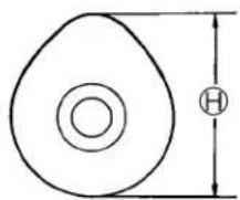
natural_image
Simple geometric diagram showing a teardrop-shaped object with concentric circles and a labeled dimension H (no text or symbols beyond the label)CAMSHAFT JOURNAL WEAR
Determine whether or not each journal is worn down to the limit by measuring the oil clearance with the camshaft installed in place. Use the plastigauge Ⓐ to read the clearance at the widest portion, which is specified as follows:
DATA
Camshaft journal oil clearance
Service Limit (IN & EX): 0.150 mm (0.0059 in)
TOOL
09900-22301: Plastigauge
09900-22302: Plastigauge
NOTE:
Install camshaft journal holder to their original positions.
Tighten the camshaft journal holder bolts evenly and diagonally to the specified torque.
[NO TEXT]
Camshaft journal holder bolt: 10 N·m (1.0 kgf·m, 7.0 lb·ft)
NOTE:
Do not rotate the camshaft with the plastigauge in place.
Remove the camshaft holders, and read the width of the compressed plastigauge with envelope scale. This measurement should be taken at the widest part.
If the camshaft journal oil clearance measured exceeds the limit, measure the inside diameter of the camshaft journal holder and outside diameter of the camshaft journal. Replace the camshaft or the cylinder head depending upon which one exceeds the specification.
DATA
Camshaft journal holder I.D.
Standard (IN & EX):
22.012 - 22.025 mm (0.8666 - 0.8671 in)
TOOL
09900-20602: Dial gauge (1/1000, 1 mm)
09900-22403: Small bore gauge (18 - 35 mm)
DATA
Crankshaft journal O.D.
Standard (IN & EX):
21.972 - 21.993 mm (0.8650 - 0.8659 in)
TOOL
09900-20205: Micrometer (0 - 25 mm)

natural_image
Mechanical assembly diagram showing gears and housing components (no visible text or labels)
natural_image
Close-up of a mechanical assembly with gears and shafts (no visible text or symbols)
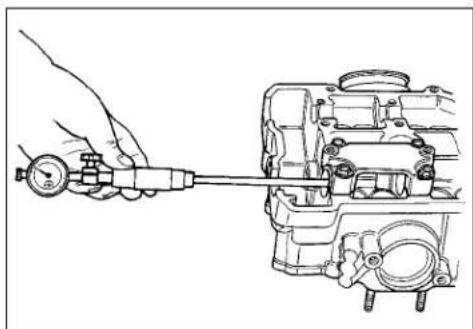
natural_image
Line drawing of a hand using a dial indicator to measure the internal components of a mechanical engine (no text or symbols present)
natural_image
Line drawing of hands using a mechanical tool to adjust or install a mechanical component (no text or symbols present)CAMSHAFT RUNOUT
Measure the runout with a dial gauge. Replace the camshaft if the runout exceeds the limit.

Camshaft runout
Service Limit (IN & EX): 0.10 mm (0.004 in)

09900-20607: Dial gauge (1/100 mm, 10 mm)
09900-20701: Magnetic stand
09900-21304: V-block (100 mm)
CAM GEAR AND AUTOMATIC-DECOMP.
Inspect the cam gear teeth for wear and damage.
Inspect the automatic-decomp. for damage and smooth operation.
If there are unusual, replace the camshaft assembly and cam chain as a set.
CAUTION
Do not attempt to disassemble the cam gears and automatic-decomp. assembly. They are unserviceable.
CAM CHAIN TENSION ADJUSTER
The cam chain tension adjusters are maintained at the proper cam chain tension automatically.
Unlock the ratchet Ⓐ, and move the push rod Ⓑ in place to see if it slides smoothly. If any stickiness is noted or ratchet mechanism is faulty, replace the cam chain tension adjuster assembly with a new one.
① Front cam chain tension adjuster
② Rear cam chain tension adjuster
CAM CHAIN GUIDE AND CAM CHAIN TENSIONER
Check the cam chain guide and tensioner for wear and damage. If they are found to be damaged, replace them with the new ones.
③ Front cam chain tensioner
④ Rear cam chain tensioner
⑤ Front and Rear cam chain guide
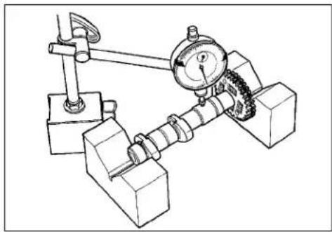
natural_image
Technical line drawing of a mechanical testing apparatus with a dial and base mount (no text or symbols)
natural_image
Close-up of four mechanical gears with directional arrows indicating assembly or movement (no text or symbols present)

CYLINDER HEAD
- Remove the tappets and shims ① by fingers or magnetic hand.

natural_image
Close-up of a mechanical component with hands adjusting parts (no visible text or symbols)
natural_image
Cross-sectional view of a mechanical component with numbered annotations (no readable text or symbols)- Using special tools, compress the valve spring and remove the two cotter halves ② from the valve stem.

09916-14510: Valve lifter
09916-14910: Valve lifter attachment
09916-84511: Tweezers
- Remove the valve spring retainer ③ and valve spring ④.


- Pull out the valve from the other side.

natural_image
Technical line drawing of an engine cylinder head assembly (no text or labels)- Remove the oil seals ① and the spring seats ②.
CAUTION
Do not reuse the removed oil seals.
CYLINDER HEAD DISTORTION
Decarbonize the combustion chambers.
Check the gasketed surface of the cylinder head for distortion with a straightedge and thickness gauge, taking a clearance reading at several places indicated. If the largest reading at any position of the straightedge exceeds the limit, replace the cylinder head.

Cylinder head distortion
Service Limit: 0.05 mm (0.002 in)

09900-20803: Thickness gauge
VALVE STEM RUNOUT
Support the valve with "V" blocks, as shown, and check its runout with a dial gauge.
The valve must be replaced if the runout exceeds the limit.

Valve stem runout
Service Limit: 0.05 mm (0.002 in)

09900-20607: Dial gauge (1/100 mm)
09900-20701: Magnetic stand
09900-21304: V-block (100 mm)
VALVE HEAD RADIAL RUNOUT
Place the dial gauge at right angles to the valve head face, and measure the valve head radial runout.
If it measures more than the limit, replace the valve.

Valve head radial runout
Service Limit: 0.03 mm (0.001 in)

09900-20607: Dial gauge (1/100 mm)
09900-20701: Magnetic stand
09900-21304: V-block (100 mm)

natural_image
Mechanical assembly diagram showing internal components with numbered annotations (no readable text or symbols)
natural_image
Cross-sectional view of a mechanical engine cylinder head with internal cavities (no text or symbols visible)
natural_image
Technical line drawing of a mechanical testing setup with a dial indicator and clamped components (no text or symbols)
natural_image
Technical line drawing of a mechanical device with a dial indicator and lever mechanism (no text or symbols)VALVE FACE WEAR
Visually inspect each valve for wear of its seating face. Replace any valve with an abnormally worn face. The thickness decreases as the wear of the face advances.
Measure the thickness and, if the thickness is found to have been reduced to the limit, replace it.

Valve head thickness®
Service Limit: 0.5 mm (0.02 in)

09900-20101: Vernier calipers
VALVE STEM DEFLECTION
Lift the valve about 10 mm (0.39 in) from the valve seat.
Measure the valve stem deflection in two directions, "X" and "Y", perpendicular to each other, by positioning the dial gauge as shown. If the deflection measured exceeds the limit, (see below) then determine whether the valve or the guide should be replaced with a new one.

Valve stem deflection (IN & EX)
Service Limit: 0.35 mm (0.014 in)

09900-20607: Dial gauge (1/100 mm)
09900-20701: Magnetic stand
VALVE STEM WEAR
If the valve stem is worn down to the limit, as measured with a micrometer, where the clearance is found to be in excess of the limit indicated, replace the valve; if the stem is within the limit, then replace the guide. After replacing valve or guide, be sure to recheck the clearance.

Valve stem O.D.
Standard (IN) : 5.475 - 5.490 mm (0.2156 - 0.2161 in)
(EX): 5.455 - 5.470 mm (0.2148 - 0.2154 in)

09900-20205: Micrometer (0 - 25 mm)
NOTE:
If valve guides have to be removed for replacement after inspecting related parts, carry out the steps shown in valve guide servicing.
VALVE GUIDE SERVICING
- Using the valve guide remover, drive the valve guide out toward the intake or exhaust camshaft side.

09916-44910: Valve guide remover/installer
NOTE:
* Discard the removed valve guide subassemblies.
* Only oversized valve guides are available as replacement parts. (Part No.11115-32E70)
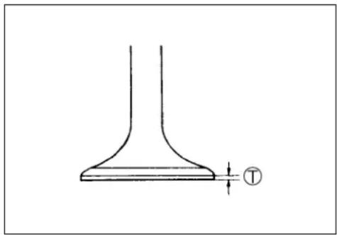
natural_image
Simple line drawing of a conical object with a base and top, marked with a dimension symbol (no text or labels)
natural_image
Technical line drawing of a mechanical assembly with a dial indicator (no text or symbols)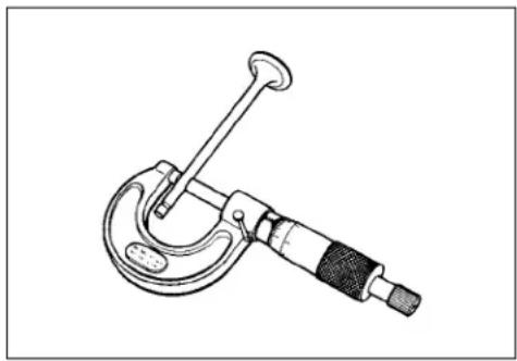
natural_image
Line drawing of a micrometer tool (no text or symbols present)
- Re-finish the valve guide holes in cylinder head with the reamer and handle.

09916-34580: Valve guide reamer 9916-34542: Reamer handle
- Oil the stem hole, too, of each valve guide and drive the guide into the guide hole with the valve guide installer and attachment.

09916-44910: Valve guide remover/installer 9916-53340: Attachment
CAUTION
Failure to oil the valve guide hole before driving the new guide into place may result in a damaged guide or head.
• After fitting the valve guides, re-finish their guiding bores with the reamer. Be sure to clean and oil the guides after reaming.

09916-34550: Valve guide reamer 9916-34542: Reamer handle
NOTE:
Insert the reamer from the combustion chamber and always turn the reamer handle clockwise.
VALVE SEAT WIDTH
- Coat the valve seat uniformly with Prussian blue. Fit the valve and tap the coated seat with the valve face in a rotating manner, in order to obtain a clear impression of the seating contact. In this operation, use the valve lapper to hold the valve head.


- The ring-like dye impression left on the valve face must be continuous without any break. In addition, the width of the dye ring, which is the visualized seat "width", must be within the following specification:

Valve seat width W
Standard: 0.9 – 1.1 mm (0.035 – 0.043 in)

09916-10911: Valve lapper set
If either requirement is not met, correct the seat by servicing is as follows:
VALVE SEAT SERVICING
The valve seats for both intake and exhaust valves are machined to four different angles. (The seat contact surface is cut 45°.)
| INTAKE EXHAUST | |
| 45° N-615 or N-626 N-615 or N-626 | |
| 60° N-211 N-211 | |
| 15° N-615 | |
| 30° N-626 | |
NOTE:
The valve seat contact area must be inspected after each cut.

09916-21111: Valve seat cutter set
09916-24210: Valve seat cutter (N-615)
09916-24480: Solid pilot (N-140-5.5)
09916-24810: Valve seat cutter (N-626)
09916-27710: Valve seat cutter (N-211)
- Insert the solid pilot with a slight rotation. Seat the pilot snugly. Install the 45irc cutter, attachment and T-handle.
- Using the 45irc cutter, descale and clean up the seat with one or two turns.
- Inspect the seat by the previously described seat width measurement procedure. If the seat is pitted or burned, additional seat conditioning with the 45irc cutter is required.
NOTE:
Cut only the minimum amount necessary from the seat to prevent the possibility of the tappet shim replacement.
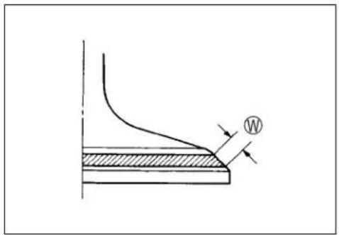


If the contact area is too high on the valve, or if it is too wide, use the 15irc/60irc cutters (for exhaust side) and 30irc/60irc cutters (for intake side) to lower and narrow the contact area.
Contact area too high and too wide on face of valve

natural_image
Pure technical diagram showing a curved line and a shaded rectangular area with an arrow, no text or symbols present.If the contact area is too low or too narrow, use the 45irc cutter to raise and widen the contact area.
Contact area too low and too narrow on face of valve

natural_image
Pure technical diagram showing a curved line and a labeled point W, without any text or symbols• After the desired seat position and width is achieved, use the 45irc cutter very lightly to clean up any burrs caused by the previous cutting operations.
CAUTION
DO NOT use lapping compound after the final cut is made. The finished valve seat should have a velvety smooth finish and not a highly polished or shiny finish.
This will provide a soft surface for the final seating of the valve which will occur during the first few seconds of engine operation.
- Clean and assemble the head and valve components. Fill the intake and exhaust ports with gasoline to check for leaks. If any leaks occur, inspect the valve seat and face for burrs or other things that could prevent the valve from sealing.
WARNING
Always use extreme caution when handling gasoline.
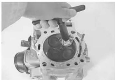
natural_image
Close-up of a hand using a tool to adjust internal components of an engine cylinder (no text or symbols visible)NOTE:
After servicing the valve seats, be sure to check the tappet clearance after the cylinder head has been reinstalled. (2-7)

natural_image
Close-up of a mechanical engine cylinder with a bottle pouring liquid (no visible text or symbols)VALVE SPRING
The force of the coil spring keeps the valve seat tight. Weakened spring results in reduced engine power output, and often account for the chattering noise coming from the valve mechanism.
Check the valve springs for proper strength by measuring their free length and also by the force required to compress them. If the spring length is less than the service limit, or if the force required to compress the spring does not fall within the range specified, replace it.

09900-20102: Vernier calipers

Valve spring free length (IN & EX)
Service Limit: 39.6 mm (1.56 in)
Valve spring tension (IN & EX)
Standard: 197 - 227 N/35.6 mm
(20.1 - 23.1 kgf/35.6 mm, 44.3 - 51.0 lbs/1.40 in)
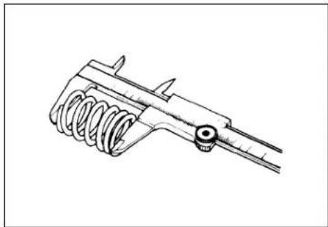
natural_image
Technical line drawing of a mechanical spring assembly (no text or symbols)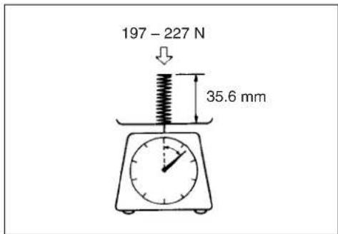
CAM DRIVE IDLE GEAR/SPROCKET THRUST CLEARANCE
Install the cam drive idle gear/sprocket ①, its shaft ②, copper washer ③ and thrust washer ④ to each cylinder head. Tighten the shaft ② to the specified torque. Use a thickness gauge to measure the thrust clearance between the cylinder head and the thrust washer ④.

Cam drive idle gear/sprocket thrust clearance Standard: 0.15 – 0.29 mm (0.006 – 0.011 in)
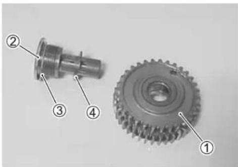

Cam drive idle gear/sprocket shaft: 40 N·m (4.0 kgf-m, 29.0 lb-ft)

09900-20803: Thickness gauge
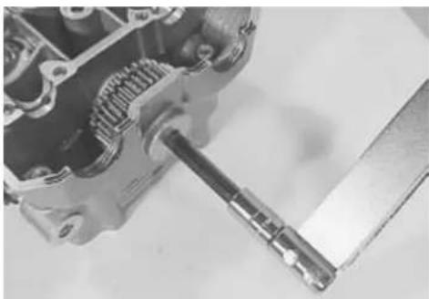
natural_image
Close-up of mechanical gear and shaft assembly (no visible text or symbols)If the thrust clearance exceeds the standard range, adjust the thrust clearance by the following procedures:
- Remove the thrust washer, and measure its thickness with a micrometer.
- Change the thrust washer with the other washer if the thrust clearance is incorrect.
- Perform the thrust clearance measurement described above once again checking to make sure it is within standard.

09900-20205: Micrometer (0 - 25 mm)
Unit: mm (in)
| Color/Mark(Part No.) | Thrust washer thickness Ⓐ |
| Blue(09181-15182) | 1.38 – 1.42(0.054 – 0.056) |
| Yellow(09181-15181) | 1.28 – 1.32(0.050 – 0.052) |
| Light blue(09181-15176) | 1.18 – 1.22(0.046 – 0.048) |
| Light green(09181-15172) | 1.08 – 1.12(0.043 – 0.044) |
| Brown(09181-15166) | 0.98 – 1.02(0.039 – 0.040) |
| “J” mark(09181-15164) | 0.88 – 0.92(0.035 – 0.036) |

natural_image
Close-up of a mechanical assembly with gears and housing (no visible text or symbols)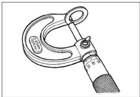
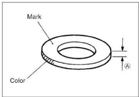
CYLINDER HEAD REASSEMBLY
• Install the valve spring seats.
- Oil each oil seal, and press-fit them into position with the valve guide installer.

09916-44910: Valve guide remover/installer
CAUTION
Do not reuse the removed oil seals.
- Insert the valves, with their stems coated with molybdenum oil solution all around and along the full stem length without any break.
CAUTION
When inserting each valve, take care not to damage the lip of the oil seal.

natural_image
Close-up of an internal mechanical component with a tool labeled 'TOOL' pointing to a pipe or shaft (no readable text beyond label)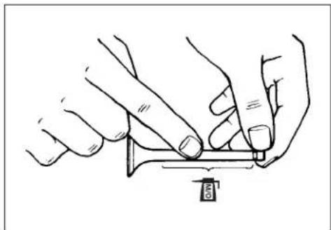
natural_image
Illustration of hands using a caliper to apply a small object (no text or symbols present)
MOLYBDENUM OIL
- Install the valve spring with the small-pitch portion Ⓐ facing cylinder head.
⑧: Large-pitch portion
- Put on the valve spring retainer, and using the valve lifter, press down the spring, fit the cotter halves to the stem end, and release the lifter to allow the cotter ① to wedge in between retainer and stem. Be sure that the rounded lip ⑥ of the cotter fits snugly into the groove ⑭ in the stem end.

09916-14510: Valve lifter
09916-14910: Valve lifter attachment
09916-84511: Tweezers
CAUTION
Be sure to restore each spring and valve to their original positions.
• Install the tappet shim and tappet to their original position.
* Apply engine oil to the shim and tappet before fitting them.
* When seating the tappet shim, be sure the figure printed surface faces the tappet.
NOTE:
INTAKE PIPE/WATER UNION
- Remove the intake pipe.

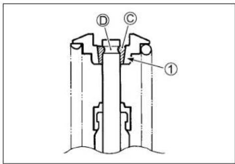

natural_image
Close-up of mechanical components with a tool labeled 'TOOL' pointing to a cylindrical component (no readable text or symbols beyond the label)
natural_image
Close-up of a mechanical component with a hand holding a button (no visible text or symbols)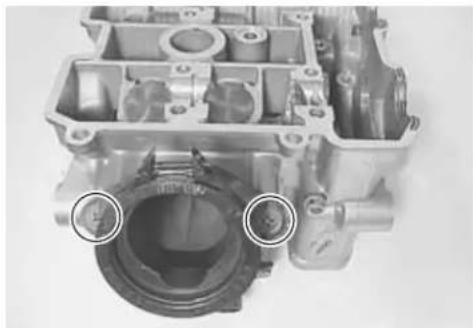
natural_image
Close-up of a mechanical engine component with two circular features, no visible text or symbols- Remove the water union.
- When installing the intake pipe, apply grease to the O-ring.
NOTE:
"UP" mark faces upward.

99000-25030: SUZUKI SUPER GREASE "A" (USA) 9000-25010: SUZUKI SUPER GREASE "A" (Others)
CAUTION
Use the new O-ring to prevent air from sucking through the joint.
- Apply engine coolant to the new O-ring and install the water union.

natural_image
Close-up of a mechanical component with a circular feature and a threaded shaft (no visible text or symbols)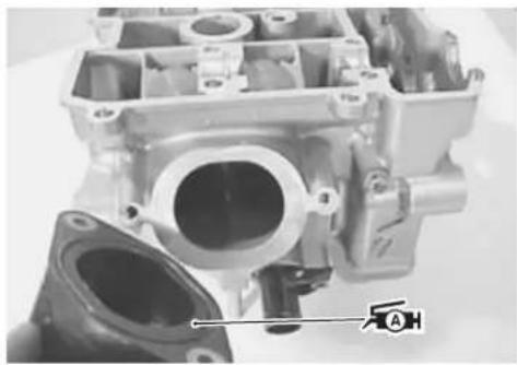
natural_image
Close-up of a mechanical component with internal cavities and mounting holes (no visible text or symbols)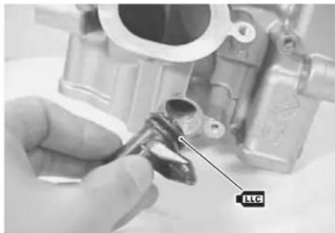
natural_image
Close-up of a hand using a tool to adjust a mechanical component (no visible text or symbols)CYLINDER/PISTON INSPECTION CYLINDER DISTORTION
Check the gasketed surface of the cylinder for distortion with a straightedge and thickness gauge, taking a clearance reading at several places as indicated. If the largest reading at any position of the straightedge exceeds the limit, replace the cylinder.

Cylinder distortion Service Limit: 0.05 mm (0.002 in)

09900-20803: Thickness gauge
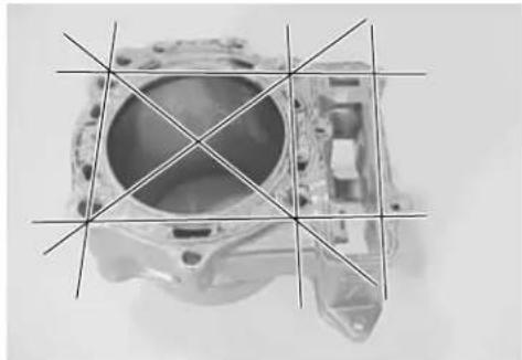
natural_image
Top-down view of a mechanical component with visible internal structure and grid lines (no text or symbols)CYLINDER BORE
Inspect the cylinder wall for any scratches, nicks or other damage. Measure the cylinder bore diameter at six places.

Cylinder bore
Standard: 98.000 - 98.015 mm (3.8583 - 3.8589 in)

09900-20508: Cylinder gauge set
PISTON DIAMETER
Using a micrometer, measure the piston outside diameter at 10 mm (0.4 in) from the piston skirt end. If the measurement is less than the limit, replace the piston.

Piston diameter
Service Limit: 97.880 mm (3.8535 in)

09900-20204: Micrometer (75 - 100 mm)
PISTON-TO-CYLINDER CLEARANCE
As a result of the previous measurement, if the piston to cylinder clearance exceeds the following limit, replace both cylinder and piston.

Piston to cylinder clearance
Service Limit: 0.12 mm (0.0047 in)

natural_image
Technical line drawing of a mechanical component with a dial indicator (no text or symbols)
natural_image
Technical drawing of a mechanical component with cross-sectional and top views (no text or symbols)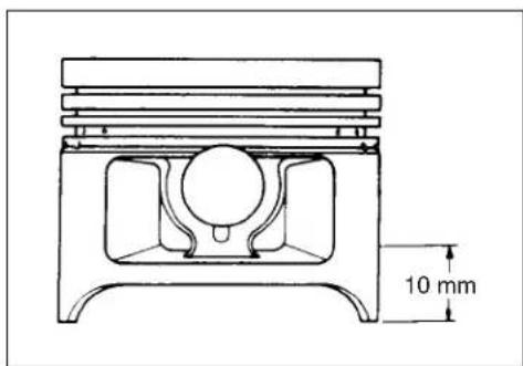

natural_image
Technical line drawing of a micrometer caliper assembly (no text or labels)PISTON RING TO GROOVE CLEARANCE
Using a thickness gauge, measure the side clearances of the 1st and 2nd rings. If any of the clearances exceeds the limit, replace both piston and piston rings.

Piston ring to groove clearance
Service Limit (1st) : 0.18 mm (0.0071 in)
(2nd) : 0.15 mm (0.0059 in)

Piston ring groove width
Standard (1st) : 0.93 - 0.95 mm (0.0366 - 0.0374 in)
1.55 - 1.57 mm (0.0610 - 0.0618 in)
(2nd): 1.01 - 1.03 mm (0.0398 - 0.0406 in)
(Oil): 2.51 - 2.53 mm (0.0988 - 0.0996 in)

Piston ring thickness
Standard (1st) : 0.86 - 0.91 mm (0.034 - 0.036 in)
1.38 - 1.40 mm (0.054 - 0.055 in)
(2nd): 0.97 - 0.99 mm (0.038 - 0.039 in)

09900-20803: Thickness gauge
09900-20205: Micrometer (0 - 25 mm)
PISTON RING FREE END GAP AND PISTON RING END GAP
Before installing piston rings, measure the free end gap of each ring using vernier calipers. Next, fit the ring in the cylinder, and measure each ring end gap using a thickness gauge. If any ring has an excess end gap, replace the ring.

Piston ring free end gap
Service Limit (1st) : 7.0 mm (0.28 in)
(2nd): 8.1 mm (0.32 in)

09900-20101: Vernier caliper

Piston ring end gap
Service Limit (1st) : 0.5 mm (0.02 in)
(2nd) : 0.7 mm (0.03 in)

09900-20803: Thickness gauge

natural_image
Line drawing of hands holding a cylindrical mechanical component with a shaft (no text or symbols)
natural_image
Pure mechanical cross-section diagram without any text, numbers, or symbols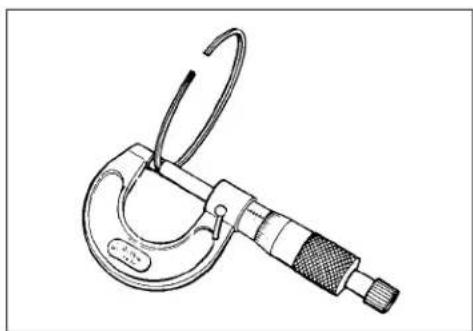
natural_image
Line drawing of a micrometer (no text or symbols present)
natural_image
Line drawing of a vernier caliper with a ring handle and scale (no text or symbols)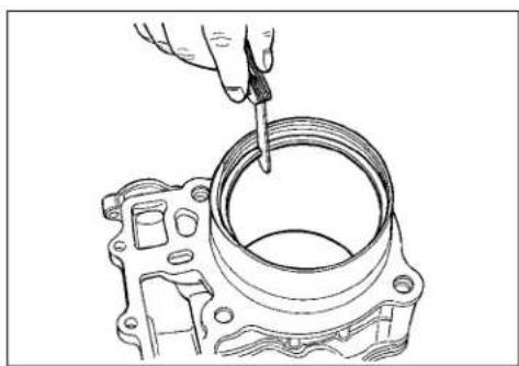
natural_image
Line drawing of a hand using a dropper to inspect a mechanical component (no text or symbols)PISTON PIN AND PIN BORE
Using a small bore gauge, measure the piston pin bore inside diameter, and using a micrometer, measure the piston pin outside diameter. If the difference between these two measurements is more than the limits, replace both piston and piston pin.

Piston pin bore I.D.
Service limit: 22.030 mm (0.8673 in)

09900-20602: Dial gauge (1/1000 mm, 1 mm)
09900-22403: Small bore gauge (18 - 35 mm)
Using a micrometer, measure the piston pin outside diameter at three positions.

Piston pin O.D.
Service Limit: 21.980 mm (0.8654 in)

09900-20205: Micrometer (0 - 25 mm)
CONROD/CRANKSHAFT
CONROD SMALL END I.D.
Using a small bore gauge, measure the inside diameter of the conrod small end.

09900-20602: Dial gauge (1/1000 mm, 1 mm)
09900-22403: Small bore gauge (18 - 35 mm)

Conrod small end I.D.
Service Limit: 22.040 mm (0.8677 in)
If the inside diameter of the conrod small end exceeds the limit, replace the conrod.
CONROD BIG END SIDE CLEARANCE
Check the conrod side clearance by using a thickness gauge. If the clearance exceeds the limit, replace conrod or crankshaft.

Conrod big end side clearance
Service Limit: 0.50 mm (0.020 in)

09900-20803: Thickness gauge
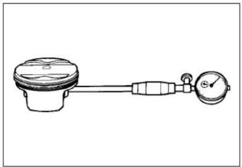
natural_image
Line drawing of a mechanical device with a piston and pressure gauge (no text or symbols)
natural_image
Technical line drawing of a micrometer caliper with no visible text or symbols
natural_image
Hand holding a dial indicator measuring a mechanical component (no text or symbols visible)
natural_image
Mechanical component with attached lever and cylindrical shaft (no visible text or symbols)
Conrod big end width
Standard: 21.95 - 22.00 mm (0.864 - 0.866 in)

Crank pin width
Standard: 44.17 - 44.22 mm (1.739 - 1.741 in)

09900-20205: Micrometer (0 - 25 mm)

natural_image
Technical line drawings of mechanical tools and gauges (no text or symbols)CONROD-CRANK PIN BEARING INSPECTION
- Loosen the bearing cap bolts, and tap the bearing cap bolt lightly with plastic hammer to remove the bearing cap.
CAUTION
Never reuse the bearing cap bolt.
- Remove the conrods, and mark them to identify the cylinder position.
- Inspect the bearing surfaces for any sign of fusion, pitting, burn, or flaws. If any, replace them with a specified set of bearings.

natural_image
Close-up of a mechanical component with metallic parts and a white cylindrical part (no visible text or symbols)
natural_image
Two metallic mechanical components with curved and flat ends, no visible text or symbolsCONROD-CRANK PIN BEARING SELECTION
- Place plastigauge axially on the crank pin avoiding the oil hole, at TDC or BDC side as shown.
- Tighten the bearing cap bolts as the specified manner.

09900-22301: Plastigauge
09900-22302: Plastigauge

natural_image
Technical line drawing of a mechanical component with flanged ends and threaded ports (no text or symbols)NOTE:
Never rotate the crankshaft or conrod when a piece of plastigauge is in the clearance.
- Remove the caps and measure the width of compressed plastigauge with envelope scale. This measurement should be taken at the widest part.
DATA
Conrod big end oil clearance
Service Limit: 0.080 mm (0.0031 in)
- If oil clearance exceeds the service limit, select the specified bearings from the bearing selection table.
- Check the corresponding conrod I.D. code number Ⓐ, "1" or "2".
- Check the corresponding crank pin O.D. code number Ⓑ, "1", "2" or "3" stamped on the left crank web.
Bearing selection table
| Crank pin O.D. 8 | ||||
| Code 1 | 2 | 3 | ||
| Conrod I.D. code A | 1 Green Black Brown | |||
| 2 Black Brown Yellow | ||||
DATA
Conrod big end oil clearance
Standard: 0.040 - 0.064 mm (0.0016 - 0.0025 in)


natural_image
Close-up of a mechanical component with two labeled points A, showing internal features and shafts (no text or symbols beyond labels)
Conrod big end I.D. specification
| Code A I.D. specification | |
| 1 | 48.000 – 48.008 mm(1.8898 – 1.8900 in) |
| 2 | 48.008 – 48.016 mm(1.8900 – 1.8904 in) |
Crank pin O.D. specification
| Code B O.D. specification | |
| 1 | 44.992 – 45.000 mm(1.7713 – 1.7717 in) |
| 2 | 44.984 – 44.992 mm(1.7710 – 1.7713 in) |
| 3 | 44.976 – 44.984 mm(1.7707 – 1.7710 in) |

natural_image
Technical line drawing of a mechanical assembly with no visible text or symbols
09900-20202: Micrometer (25 - 50 mm)
Bearing thickness
| Color (Part No.) Thickness | |
| Green(12164-02F11-0A0) | 1.476 – 1.480 mm(0.0581 – 0.0583 in) |
| Black(12164-02F11-0B0) | 1.480 – 1.484 mm(0.0583 – 0.0584 in) |
| Brown(12164-02F11-0C0) | 1.484 – 1.488 mm(0.0584 – 0.0586 in) |
| Yellow(12164-02F11-0D0) | 1.488 – 1.492 mm(0.0586 – 0.0587 in) |
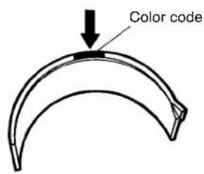
CAUTION
Bearing must be replaced as a set.
BEARING ASSEMBLY
- When fitting the bearings to the bearing cap and conrod, be sure to fix the stopper part © first, and press in the other end.
- Apply molybdenum oil solution to the crank pin and bearing surface.

MOLYBDENUM OIL

natural_image
Two-panel image showing mechanical components with arrows pointing to features, no visible text or symbols- When fitting the conrods on the crankshaft, make sure that I.D. codes Ⓐ of the conrods face each cylinder intake valve sides.
CAUTION
Never reuse the bearing cap bolt.


Apply engine oil to the bearing cap bolts.
- Tighten the bearing cap bolts as following two steps.

Conrod bearing cap bolt
(Initial) : 35 N·m (3.5 kgf-m, 25.5 lb-ft)
(Final) : After tightening the bolts to the above torque, tighten them 1/4 of a turn (90°).
- Check the conrod movement for smooth turning.

CLUTCH
CLUTCH DRIVE PLATES
NOTE:
Wipe off engine oil from the clutch drive plates with a clean rag.
Measure the thickness of drive plates with a vernier calipers. If each drive plate is not within the standard range, replace it with a new one.


Drive plate thickness
Standard (No.1): 2.92 - 3.08 mm (0.115 - 0.121 in)
(No.2 & No.3): 3.72 - 3.88 mm (0.146 - 0.153 in)

09900-20102: Vernier calipers
Measure the claw width of drive plates with a vernier calipers. Replace the drive plates found to have worn down to the limit.

Drive plate claw width (No.1 and No.2)
Standard (No.1): 13.85 – 13.96 mm (0.545 – 0.550 in)
(No.2 & No.3): 13.90 - 14.00 mm (0.547 - 0.551 in)

09900-20102: Vernier calipers
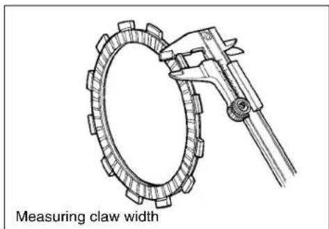
CLUTCH DRIVEN PLATES
NOTE:
Wipe off engine oil from the clutch driven plates with a clean rag.
Measure each driven plate for distortion with a thickness gauge and surface plate.
Replace driven plates which exceed the limit.

Driven plate distortion
Service Limit: 0.10 mm (0.004 in)

09900-20803: Thickness gauge
CLUTCH SPRING FREE LENGTH
Measure the free length of each coil spring with a vernier calipers, and compare the length with the specified limit. Replace all the springs if any spring is not within the limit.

Clutch spring free length
Service Limit: 59.4 mm (2.34 in)

09900-20102: Vernier calipers
CLUTCH BEARING
Inspect the clutch release bearing for any abnormality, particularly cracks, to decide whether it can be reused or should be replaced.
Smooth engagement and disengagement of the clutch depends on the condition of this bearing.
NOTE:
Thrust washer is located between the pressure plate and the bearing.


natural_image
Technical line drawing of a mechanical caliper with spring and adjustment knob (no text or symbols)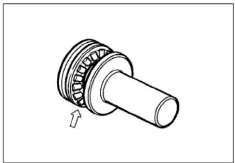
natural_image
Mechanical gear assembly diagram showing shaft and bearing (no text or labels)TRANSMISSION
CONSTRUCTION
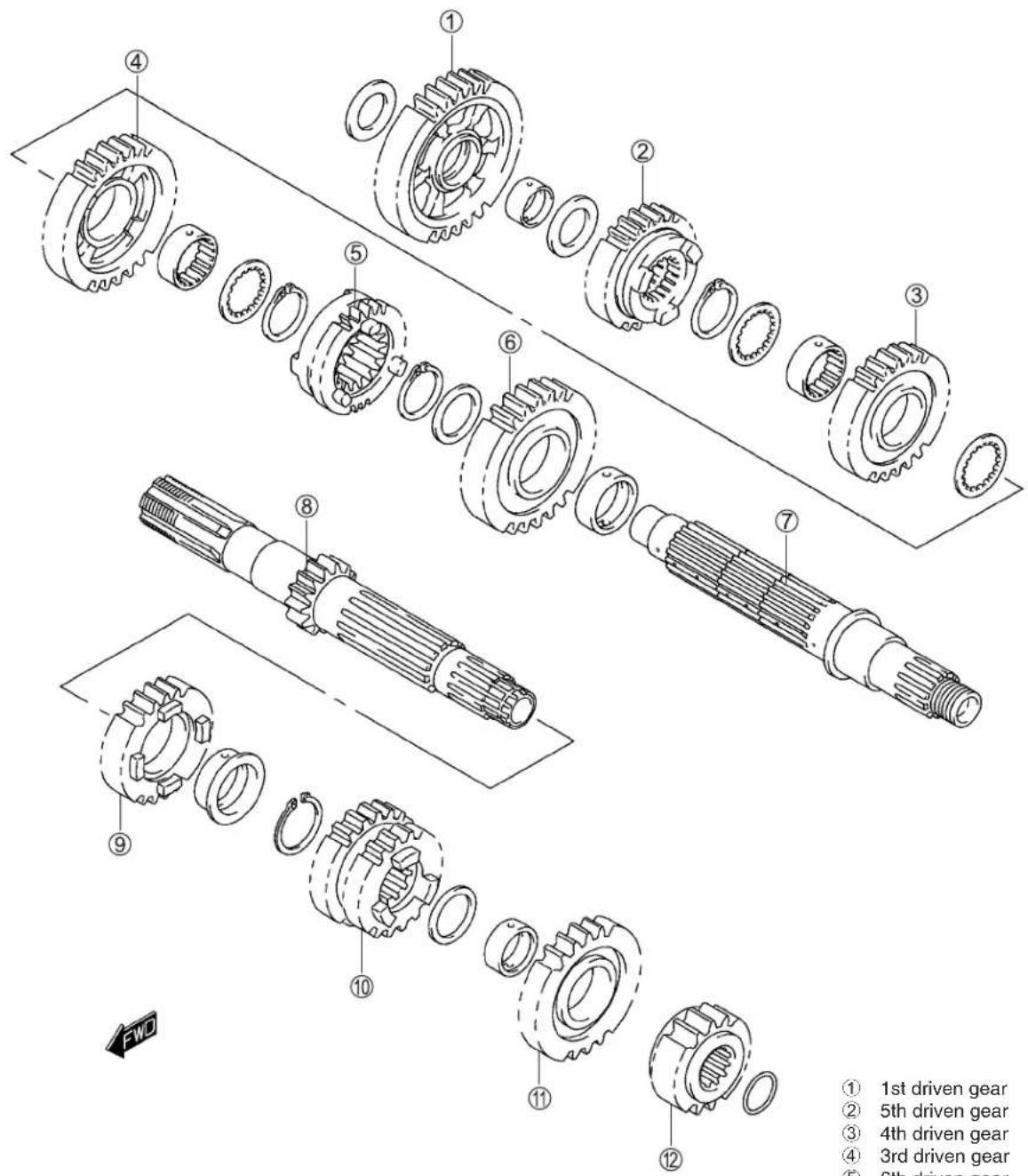
① 1st driven gear
② 5th driven gear
③ 4th driven gear
④ 3rd driven gear
⑤ 6th driven gear
⑥ 2nd driven gear
⑦ Drive shaft
⑧ Countershaft
⑨ 5th drive gear
⑩ 3rd & 4th drive gear
⑪ 6th drive gear
⑫ 2nd drive gear
DISASSEMBLY
CAUTION
Be sure to identify each removed part as to its location, and lay the parts out in groups designated as "Drive" and "Driven", so that each will be restored to the original location during assembly.
Countershaft
- Remove the O-ring ①, 2nd drive gear ② and top drive gear ③.
CAUTION
The removed O-ring must be replaced with a new one.
- Remove the top drive gear bushing ④, washer ⑤, and 3rd/4th drive gears ⑥.
- Remove the snap ring with the special tool.

09900-06107: Snap ring pliers
- Remove the 5th drive gear ⑦ and its bushing ⑧.


natural_image
Close-up of a mechanical gear assembly with visible teeth and central hub (no text or symbols)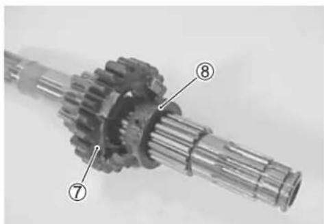
Driveshaft
- Remove the low driven gear ① and washer ②.
- Remove the low driven gear bushing ③, washer ④ and 5th driven gear ⑤.
- Remove the snap ring with the special tool.

09900-06107: Snap ring pliers
- Remove the washer ⑥, 4th driven gear ⑦ and its bushing ⑧.
- Remove the washer ⑨, 3rd driven gear⑩ and its busing ⑪.

natural_image
Close-up of a mechanical gear with labeled parts (① and ②), showing teeth and central bore (no text or symbols beyond labels)

natural_image
Close-up of a mechanical gear assembly with a shaft and gear teeth (no visible text or symbols)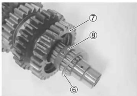

- Remove the washer ①.
- Remove the top driven gear ② by removing the snap ring.

09900-06107: Snap ring pliers
- Remove the snap ring with the special tool.

09900-06107: Snap ring pliers
- Remove the 2nd driven gear ③, its bushing ④ and washer ⑤.

REASSEMBLY
Assemble the transfer in the reverse order of disassembly. Pay attention to the following points:
NOTE:
* Always use new snap rings.
* Before installing the gears, coat lightly engine oil to the shafts and gears.
CAUTION
* Never reuse a snap ring. After a snap ring has been removed from a shaft, it should be discarded and a new snap ring must be installed.
* When installing a new snap ring, care must be taken not to expand the end gap larger than required to slip the snap ring over the shaft.
* After installing a snap ring, always ensure that it is completely seated in its groove and securely fitted.
- When installing a new snap ring, pay attention to the direction of the snap ring. Fit it to the side where the thrust is as shown in the figure.
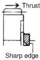
CAUTION
When installing the 3rd and 4th driven gear bushings on to the driveshaft, align the shaft oil holes A with the bushing oil hole B.


GEARSHIFT FORK
GEARSHIFT FORK TO GROOVE CLEARANCE
Using a thickness gauge, check the gearshift fork clearance in the groove of its gear.
The clearance for each gearshift fork plays an important role in the smoothness and positiveness of the shifting action.

Shift fork to groove clearance
Service Limit: 0.50 mm (0.020 in)

09900-20803: Thickness gauge
09900-20102: Vernier calipers
If the clearance checked is noted to exceed the limit specified, replace the fork or its gear, or both.


Shift fork groove width
Standard: 5.0 - 5.1 mm (0.197 - 0.201 in)


Shift fork thickness
Standard: 4.8 – 4.9 mm (0.189 – 0.193 in)

PRIMARY DRIVE GEAR
PRIMARY DRIVE GEAR INSPECTION
Visually inspect the gear teeth for wear and damage. If they are worn, replace the gear with a new one.
PRIMARY DRIVE GEAR DISASSEMBLY
- Disassemble the primary drive gear by removing the snap ring ①.

09900-06107: Snap ring pliers
①: Snap ring
②: Spring washer
③: Scissors gear
④: Spring
⑤: Primary drive gear

natural_image
Mechanical gear component with teeth and central bore (no text or symbols visible)
PRIMARY DRIVE GEAR REASSEMBLY
- Set the springs ① into the grooves.
• Install the scissors gear ②.

NOTE:
Align the holes of the primary drive gear and the scissors gear.
- Install the spring washer ③ not to cover the holes of the gears.

NOTE:
The convex side of the washer faces upward.

natural_image
Close-up of a hand holding a metallic gear with a visible crack or knot (no text or symbols)• Install the snap ring ① completely with the special tool.

09900-06107: Snap ring pliers
CAUTION
* Never reuse a snap ring.
* When installing a new snap ring, care must be taken not to expand the end gap larger than required to slip a snap ring over the gear.
* After installing a snap ring, always insure that it is completely seated in its groove and securely fitted.
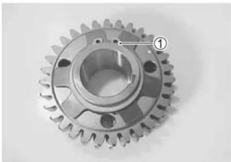
natural_image
Close-up of a mechanical gear with teeth and central bore (no text or symbols visible)STARTER TORQUE LIMITER
STARTER TORQUE LIMITER INSPECTION
CAUTION
Do not attempt to disassemble the starter torque limiter.
The starter torque limiter is available only as an assembly.

natural_image
Close-up of a mechanical gear component with visible teeth and central shaft (no text or symbols)- Check the slip torque with the special tools.

09930-73110: Starter torque limiter holder①
09930-73120: Starter torque limiter socket ②

Slip torque
Standard: 20 - 45 N·m
(2.0 - 4.5 kgf-m, 14.5 - 32.5 lb-ft)

- Set the starter torque limiter to the special tools and vise as shown in the illustration.
- If the slip torque is not within the specification, replace the starter torque limiter with a new one.
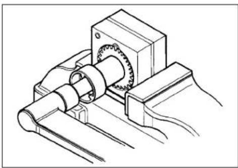
natural_image
Technical line drawing of a mechanical assembly with gears and shafts (no text or symbols)STARTER CLUTCH
DISASSEMBLY
- Remove the starter clutch securing bolts by holding the rotor with the special tool.

09930-44541: Rotor holder
REASSEMBLY
• Install the starter clutch in the proper direction.
NOTE:
* When installing the starter clutch onto the rotor, face the flange side Ⓐ of the one way clutch to the rotor.
* The arrow mark Ⓑ must face to the engine side.
- Apply engine oil to the starter clutch.
- Apply THREAD LOCK SUPER "1303" to the bolts, and then tighten them to the specified torque with the special tool.

Starter clutch bolt: 26 N·m (2.6 kgf-m, 19.0 lb-ft)

99000-32030: THREAD LOCK SUPER "1303"

09930-44541: Rotor holder
INSPECTION
• Install the starter driven gear to the starter clutch.
- Check that the starter driven gear turns in the opposite direction of the arrow mark © on the rotor while holding the generator rotor. The gear never turns in the direction of the arrow.
- If there is anything unusual, replace the one way clutch.
Inspect the starter driven gear bushing for any damage.
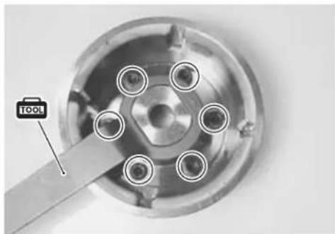
natural_image
Close-up of a mechanical component with circular holes and a tool inserted, no visible text or symbols
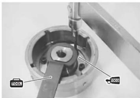
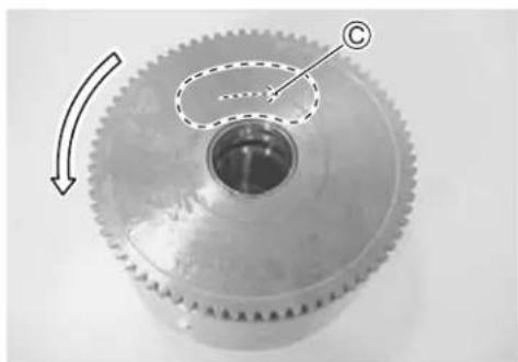
natural_image
Close-up of a mechanical gear with a central bore and dashed outline highlighting a section (no text or symbols)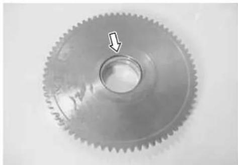
natural_image
Close-up of a metallic gear with visible teeth and central bore, marked by an arrow (no text or symbols)GEARSHIFT
GEARSHIFT SHAFT/GEARSHIFT ARM DISASSEMBLY
- Remove the following parts from the gearshift shaft/gearshift arm ①.
② Washer
⑥ Plate return spring
③ Snap ring
⑦ Washer
④ Gearshift shaft return spring
⑧ Snap ring
⑤ Gearshift cam drive plate
⑨ Washer

09900-06107: Snap ring pliers
GEARSHIFT SHAFT/GEARSHIFT ARM INSPECTION
Check the gearshift shaft/gearshift arm ① for wear or bend.
RETURN SPRINGS INSPECTION
Check the return springs, ④ and ⑥, for damage or fatigue.
GEARSHIFT SHAFT/GEARSHIFT ARM REASSEMBLY
• Install the following parts to the gearshift shaft/gearshift arm ① as shown in the right illustration.
② Washer
⑥ Plate return spring
③ Snap ring
⑦ Washer
④ Gearshift shaft return spring
⑧ Snap ring
⑤ Gearshift cam drive plate
⑨ Washer

09900-06107: Snap ring pliers
NOTE:
When installing the gearshift shaft return spring ④, position the stopper Ⓐ of the gearshift arm between the shaft return spring ends ⑧.
CRANKCASE
OIL PUMP
- Remove the oil pump.
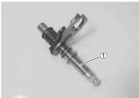
natural_image
Mechanical component with threaded shaft and mounting bracket, labeled with number 1 (no text or symbols on the object itself)
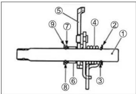


natural_image
Close-up of mechanical components with circular annotations highlighting specific parts (no readable text or symbols)- Rotate the oil pump by hand and check that it moves smoothly.
- If it does not move smoothly, replace the oil pump assembly.
CAUTION
Do not attempt to disassemble the oil pump assembly. The oil pump is available only as an assembly.
OIL PRESSURE REGULATOR
- Remove the oil pressure regulator ①.
- When installing the oil pressure regulator, apply engine oil to the new O-ring.
Check the operation of the oil pressure regulator by pushing on the piston with a proper bar. If the piston does not operate, replace the oil pressure regulator with a new one.
OIL PRESSURE SWITCH
- Remove the oil pressure switch ①.
- When installing the oil pressure switch, apply SUZUKI BOND "1215" to the thread.

Oil pressure switch: 14 N·m (1.4 kgf-m, 10.0 lb-ft)

99000-31110: SUZUKI BOND "1215"
OIL JET
- Remove the oil gallery plug.
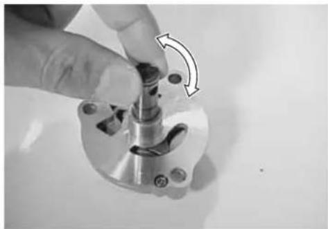
natural_image
Close-up of a hand turning a mechanical component with an arrow indicating rotation (no text or symbols visible)
natural_image
Mechanical assembly diagram showing two views of a mechanical component with labeled parts (no readable text or symbols)
natural_image
Close-up of a hand holding a cylindrical mechanical component (no visible text or symbols)
natural_image
Close-up of mechanical components with numbered annotations (1 and 1215), no readable text or symbols beyond labels
natural_image
Close-up of a mechanical component with a central bolt and mounting holes (no visible text or symbols)- Remove the oil jet with a suitable bar.
- Remove the oil jet.
Check the oil jets for clogging. If they are clogged, clean their oil passage with a proper wire or compressed air.
• Fit the new O-ring to the oil jet.
CAUTION
Use the new O-ring to prevent oil leakage.
NOTE:
Apply engine oil to the O-ring when installing the oil jet.
• Install the oil jet with a suitable bar.
- Tighten the oil gallery plug to the specified torque.

Oil gallery plug (M8): 18 N·m (1.8 kgf-m, 13.0 lb-ft)

natural_image
Close-up of a mechanical assembly with gears and shafts, no visible text or symbols
natural_image
Close-up of a mechanical component with circular holes and internal cavities (no visible text or symbols)
natural_image
Two metallic mechanical components, one cylindrical and one curved, shown against a plain background (no text or symbols visible)
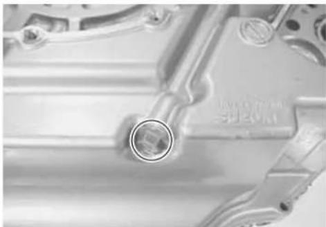
natural_image
Close-up of a mechanical component with a circular bolt and mounting holes (no visible text or symbols)- Apply engine oil to the new O-ring and install it.
- Apply THREAD LOCK "1342" to the screw and tighten it to the specified torque.

Piston cooling oil nozzle screw: 8 N·m (0.8 kgf-m, 6.0 lb-ft)

99000-32050: THREAD LOCK "1342"
- When replacing the gearshift arm stopper bolt, apply THREAD LOCK SUPER "1303" to it.

Gearshift arm stopper bolt: 23 N·m (2.3 kgf-m, 16.5 lb-ft)

99000-32030: THREAD LOCK SUPER "1303"
BEARING/OIL SEAL
Rotate the bearing inner race by finger to inspect for abnormal play, noise and smooth rotation while the bearings are in the crankcase.
Replace the bearing in the following procedure if there is anything unusual.
- Remove the oil seal retainer ①.

natural_image
Close-up of a mechanical component with a finger inserted, showing no visible text or symbols
natural_image
Close-up of a mechanical component with circular holes and a metal bracket (no visible text or symbols)
natural_image
Close-up of a hand adjusting a mechanical component with a labeled part (15.08) and no visible text or symbols.

natural_image
Close-up of mechanical gear components with no visible text or symbols- Remove the oil seal.
CAUTION
The removed oil seal must be replaced with a new one.
- Remove the oil seal with the special tool.

09913-50121: Oil seal remover
CAUTION
The removed oil seal must be replaced with a new one.
- Remove the bearing retainers.
- Remove the bearings with the special tool.

09921-20240: Bearing remover set
NOTE:
If there is no abnormal noise, the bearing removal is not necessary.
• Install the bearings with the special tool.

09913-70210: Bearing installer set
NOTE:
The sealed side of the driveshaft bearing must face outside.

natural_image
Close-up of mechanical components including gears and a shaft assembly (no visible text or symbols)
natural_image
Close-up of a mechanical component with a labeled tool (no readable text or symbols)
natural_image
Close-up of mechanical bearing assembly showing two views (top and side) with bolt holes and central bore (no text or symbols visible)
natural_image
Mechanical assembly with a tool labeled 'TOOL' pointing to a mechanical component (no readable text or symbols beyond label)
natural_image
Close-up of mechanical components with a tool labeled 'TOOL' and a hand adjusting a circular component (no readable text or symbols)• Install the bearing retainers.
NOTE:
When installing the bearing retainers, apply THREAD LOCK to the screws.

09900-32050: THREAD LOCK "1342"
• Install the oil seals with the special tool.

09913-70210: Bearing installer set
• Install the oil seal retainer.
CRANKCASE-CRANKSHAFT BEARING CRANKCASE-CRANKSHAFT BEARING INSPECTION
- Inspect the crankshaft journal bearings for any damage. If any, replace them with a specified set of bearings.
- Inspect the crankshaft journal for any damage.
• Measure the crankshaft journal O.D. with the special tool.

Crankshaft journal O.D.
Standard: 47.985 - 48.000 mm (1.8892 - 1.8898 in)

09900-20202: Micrometer (25 - 50 mm)
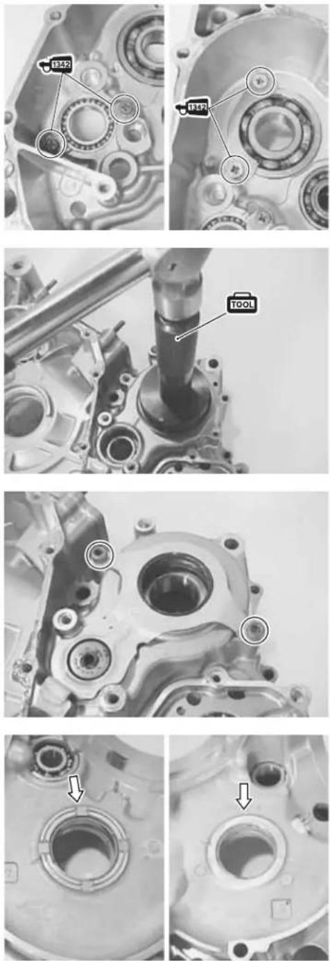

natural_image
Technical line drawing of a mechanical assembly with no visible text or symbolsCRANKCASE-CRANKSHAFT BEARING SELECTION
Select the specified bearings from the crankcase bore I.D. code. The crankcase bore I.D. code Ⓐ "A", "B" or "C", is stamped on the inside of each crankcase half.
Bearing selection table
| I.D. code Ⓐ I.D. specification Bearing | ||
| A | 52.000 – 52.006 mm(2.0472 – 2.0475 in) | Green |
| B | 52.006 – 52.012 mm(2.0475 – 2.0477 in) | Black |
| C | 52.012 – 52.018 mm(2.0477 – 2.0479 in) | Brown |
Bearing thickness
| Color (Part No.) Thickness | |
| Green(12229-06G00-0A0) | 1.996 – 1.999 mm(0.0786 – 0.0787 in) |
| Black(12229-06G00-0B0) | 1.999 – 2.002 mm(0.0787 – 0.0788 in) |
| Brown(12229-06G00-0C0) | 2.002 – 2.005 mm(0.0788 – 0.0789 in) |
CAUTION
Bearing must be replaced as a set.
CRANKSHAFT JOURNAL BEARING REPLACEMENT
- Use the special tool to replace the crankshaft journal bearings. The replacement procedure is as follows.

09913-60230: Journal bearing remover/installer
- Set the special tool as shown to remove the crankshaft journal bearings.
NOTE:
Remove the crankshaft journal bearings in only one direction, from inside to outside of each crankcase half.

natural_image
Close-up of mechanical components with labeled parts (A), no readable text or symbols present


natural_image
Close-up of a mechanical component with a labeled tool (no readable text or symbols beyond the label)- Gradually press out the bearing with the special tool by using the hand-press.
CAUTION
The removed bearings must be replaced with new ones.
NOTE:
Using the hand-press is recommended to remove the crankshaft journal bearings. However, the crankshaft journal bearings can be removed by using with the following special tools.

09924-84510: Bearing installer set 09924-74570: Final drive gear bearing remover/installer
- Set the specified crankshaft journal bearings to the special tool.
CAUTION
* Before setting the bearing, apply enough engine oil to the special tool and bearings.
* When setting the bearing, align the bearing side with the engraved line Ⓐ and also the bearing edge with the mating surface of the special tool.

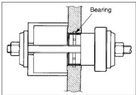

natural_image
Close-up of four metallic mechanical clamps with metal fasteners, no visible text or symbols
natural_image
Close-up of two metallic mechanical components with circular holes and a labeled point A (no text or symbols beyond label)
09913-60210: Journal bearing remover/installer set or 09913-60240: Journal bearing remover/installer
NOTE:
Journal bearing remover/installer (09913-60240) is included in Journal bearing remover/installer set (09913-60210).
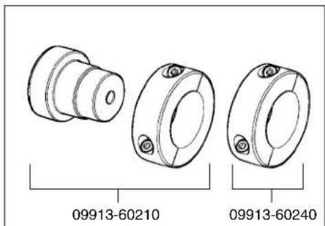
natural_image
Technical line drawing of three mechanical components with mounting holes, labeled 09913-60210 and 09913-60240 (no text or symbols on the components themselves)- Tighten the special tool bolt to the specified torque.
Special tool bolt: 23 N·m (2.3 kgf·m, 16.5 lb·ft)

CAUTION
Before installing the bearings, lightly shave off the sharp edge part of the crankcase chamfer by using an oilstone and wash the crankcase bore with enough engine oil.
- Set the bearings installed in the special tool to the crankcase half as shown.
CAUTION
* Be sure the bearing protruded sideⒶ faces the crankcase bore.
* Align the special tool mating surface with the line mark Ⓑ on the crankcase.
NOTE:
The upper and lower bearings are same.

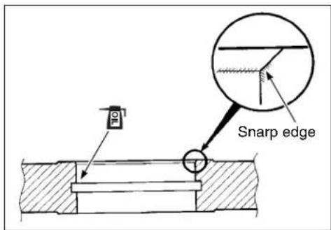
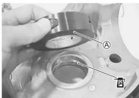
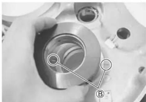
natural_image
Close-up of a mechanical component with labeled points A and B, showing internal structure (no readable text or symbols)- Apply enough engine oil to the special tool and the bearings and then set the special tool carefully.
- Gradually press in the bearing into the main journal bore by using the hand-press until the special tool ① stops the special tool ②.

09913-60230: Journal bearing remover/installer

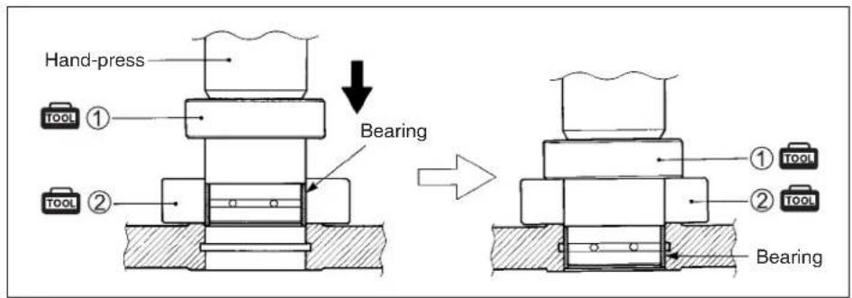
CAUTION
Use the new special tool Ⓐ (09913-60230) for DL1000. The tool Ⓐ and Ⓑ differ in length Ⓒ.

(09913-60230)

(09913-60210)
NOTE:
Using the hand-press is recommended to install the crankshaft journal bearings. However, the crankshaft journal bearings can be installed by using the following special tools.

09924-84510: Bearing installer set 09924-74570: Final drive gear bearing remover/installer

natural_image
Technical line drawing of a mechanical assembly with bolts and shafts (no text or symbols)• After installing the bearings, check the bearing surface for any scratch or damage.
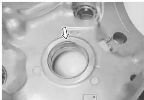
natural_image
Close-up of a mechanical component with a circular bore and mounting holes, marked by an arrow (no text or symbols visible)GENERATOR COVER
REPLACEMENT
When replacing the generator stator or crankshaft position sensor, apply THREAD LOCK "1342" to the generator stator set bolts.

99000-32050: THREAD LOCK "1342"
CLUTCH COVER
OIL SEPARATER
- Remove the oil separator ①.

natural_image
Mechanical gear assembly with mounting holes and a labeled component (no readable text or symbols)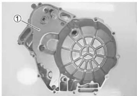
natural_image
Mechanical component diagram showing internal gear and housing structure (no text or symbols)GEARSHIFT COVER
OIL SEAL INSPECTION
Inspect the gearshift shaft oil seal for damage or wear on the lip. If any defects are found, replace the oil seal with a new one.
OIL SEAL REPLACEMENT
- Remove the gearshift shaft oil seal.
CAUTION
The removed oil seal must be replaced with a new one.
• Install the new oil seal with the special tool.

09913-70210: Bearing installer set
NOTE:
Apply grease to the oil seal lip to prevent damage when installing the gearshift cover.

99000-25030: SUZUKI SUPER GREASE "A" (USA)
99000-25010: SUZUKI SUPER GREASE "A" (Others)

natural_image
Mechanical component with a black rod inserted into a housing (no visible text or symbols)
ENGINE REASSEMBLY
Reassemble the engine in the reverse order of disassembly.
NOTE:
Apply engine oil to each running and sliding part before reassembling.
ENGINE BOTTOM SIDE
CRANKSHAFT
• Install the crankshaft into the left crankcase half.
NOTE:
Coat lightly molybdenum oil solution to the crankshaft journal bearings.

MOLYBDENUM OIL
CAUTION
Never strike the crankshaft with a plastic hammer when inserting it into the crankcase.
• Install the countershaft assembly and driveshaft assembly.
• Install the gearshift forks and gearshift cam.
NOTE:
Identify the gearshift forks as follows.
① For 3rd/4th drive gear [I.D. A: 36 mm (1.4 in), Gold]
② For 5th driven gear [I.D. Ⓐ: 40 mm (1.6 in)]
③ For 6th driven gear [I.D. Ⓐ: 40 mm (1.6 in), Gold]

natural_image
Close-up of a mechanical assembly with visible gears and housing (no text or symbols)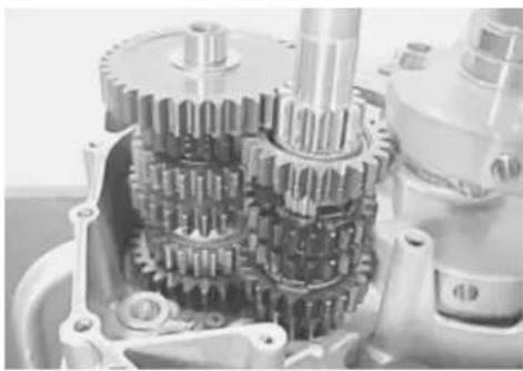
natural_image
Close-up of a mechanical gear assembly with visible teeth and shafts (no text or symbols)
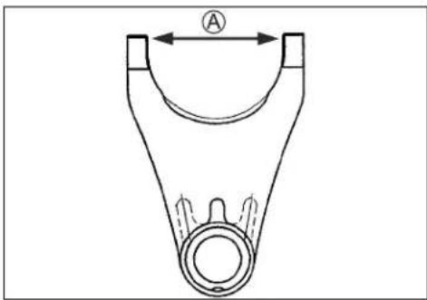
- Fit the dowel pins.
- Apply grease to the O-ring and install it.

99000-25030: SUZUKI SUPER GREASE "A" (USA) 99000-25010: SUZUKI SUPER GREASE "A" (Others)
CAUTION
Use the new O-ring to prevent oil leakage.
- Clean the mating surfaces of the left and right crankcase halves.
- Apply SUZUKI BOND "1215" to the mating surface of the left crankcase.

natural_image
Mechanical assembly diagram showing gears and shafts with mounting holes (no text or labels visible)
natural_image
Close-up of a mechanical component with a labeled section (no readable text or symbols)
99000-31110: SUZUKI BOND "1215"
NOTE:
Use of SUZUKI BOND "1215" is as follows:
* Make surfaces free from moisture, oil, dust and other foreign materials.
* Spread on surfaces thinly to form an even layer, and assemble the crankcases within few minutes.
* Take extreme care not to apply any BOND "1215" to the oil hole, oil groove and bearing.
* Apply to distorted surfaces as it forms a comparatively thick film.
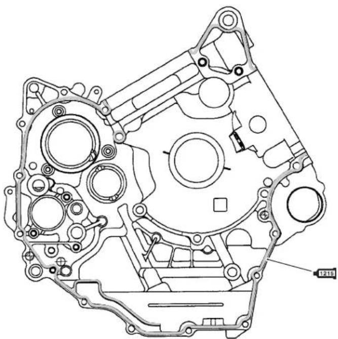
natural_image
Technical line drawing of an internal combustion engine casing (no text or labels)- When securing the right and left crankcase halves, tighten each bolt a little at a time to equalize the pressure. Tighten all the securing bolts to the specified torque values.

Crankcase bolt: (M8) 26 N·m (2.6 kgf-m, 19.0 lb-ft)
(M6) 11 N·m (1.1 kgf-m, 8.0 lb-ft)
CAUTION
Do not drop the O-ring into the crankcase when assembling the right and left crankcase halves.
NOTE:
After the crankcase bolts have been tightened, check if the crankshaft, the driveshaft and the countershaft rotate smoothly.
• Install the engine sprocket spacer ① onto the driveshaft.
CAUTION
Use the new O-ring to prevent oil leakage.
NOTE:
* The grooved Ⓐ side of the engine sprocket spacer faces crankcase side.
* Apply grease to the oil seal lip and O-ring.

99000-25030: SUZUKI SUPER GREASE "A" (USA)
99000-25010: SUZUKI SUPER GREASE "A" (Others)
GEARSHIFT
• Install the gearshift cam stopper ②, its bolt ③, washer ④ and return spring ⑤.
NOTE:
Apply a small quantity of THREAD LOCK "1342" to the gearshift cam stopper bolt ③ and tighten it to the specified torque.

99000-32050: THREAD LOCK "1342"

Gearshift cam stopper bolt: 10 N·m (1.0 kgf·m, 7.0 lb·ft)

natural_image
Mechanical assembly diagram showing internal components with circular annotations (no readable text or symbols)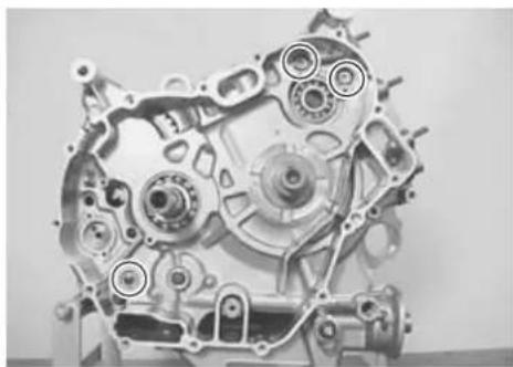
natural_image
Detailed cutaway view of an internal combustion engine showing pistons, gears, and housing (no text or labels visible)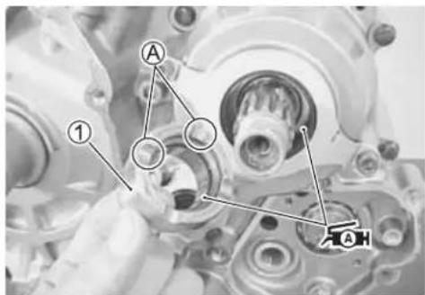

- Confirm the gearshift cam stopper movement.
- Check the neutral position.
- Install the gearshift cam stopper plate after aligning the gearshift cam pin Ⓐ with the gearshift cam stopper plate hole Ⓑ.
- Apply a small quantity of THREAD LOCK "1342" to the gear-shift cam stopper plate bolt ① and tighten it to the specified torque.

99000-32050: THREAD LOCK "1342"

Gearshift cam stopper plate bolt:
10 N·m (1.0 kgf-m, 7.0 lb-ft)
- Assembly the geafshift shaft/gearshift arm.
• Install the gearshift shaft as shown.
• Install the dowel pins and gasket ②.
CAUTION
Use new gasket to prevent oil leakage.


natural_image
Close-up of a mechanical component with a hand holding a tool, showing internal gears and a numbered label (1) — no readable text or symbols present.
natural_image
Mechanical shaft component with mounting flange and threaded end (no visible text or symbols)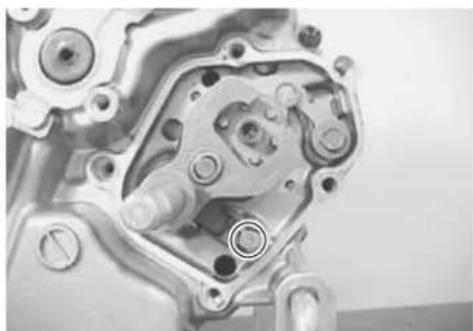
natural_image
Close-up of a mechanical gear assembly with bolts and housing (no visible text or symbols)
natural_image
Mechanical assembly diagram showing internal components with numbered annotations (no readable text or symbols)• Install the gearshift cover.
NOTE:
* Fit the clamp to the bolt Ⓐ.
* Apply grease to the oil seal lip before installing the gearshift cover.

99000-25030: SUZUKI SUPER GREASE "A" (USA) 99000-25010: SUZUKI SUPER GREASE "A" (Others)
GENERATOR ROTOR
• Install the cam drive idle gear shaft ①.
- Degrease the tapered portion of the generator rotor assembly and also the crankshaft. Use nonflammable cleaning solvent to wipe off oily or greasy matter and make these surfaces completely dry.
- Install the key ②.
• Install the generator rotor together with the starter drive gear.
• Install the generator rotor bolt.
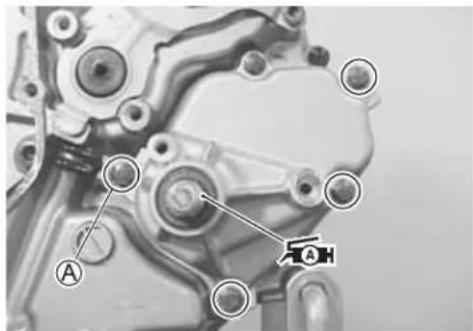

natural_image
Close-up of mechanical components with a numbered annotation (1) pointing to a specific part, no readable text or symbols present.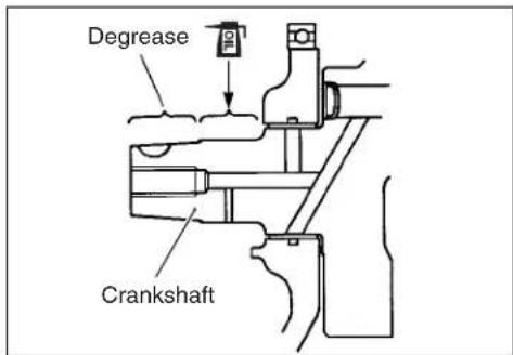

natural_image
Close-up mechanical assembly showing a cylindrical component with a numbered annotation (②) pointing to a specific part, no readable text or symbols present.
natural_image
Close-up of a hand turning a mechanical component with a tool (no visible text or symbols)- While holding the generator rotor with the special tool, tighten the bolt to the specified torque.

Generator rotor bolt: 160 N·m (16.0 kgf·m, 115.5 lb·ft)

09930-44541: Rotor holder
PRIMARY DRIVE GEAR
• Install the thrust washer onto the crankshaft.
NOTE:
The grooved side Ⓐ of the thrust washer faces the crankcase side.
- Install the key ①.
• Install the primary drive gear assembly ② and the washer ③.
NOTE:
The convex side of the washer ③ faces outside.
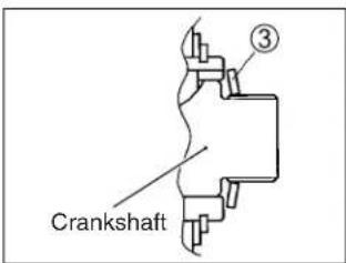
• Install the primary drive gear nut.
NOTE:
* This nut has left-hand thread.
* The "L" mark on the nut faces outside.

natural_image
Close-up of a mechanical assembly with gears and a tool labeled 'TOOL' (no readable text or symbols beyond label)
natural_image
Close-up of mechanical components with a labeled section (A) showing hands operating a gear mechanism (no readable text or symbols)
natural_image
Close-up mechanical component with numbered annotation (1), no readable text or symbols present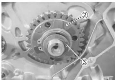
natural_image
Mechanical gear assembly with numbered components (no visible text or symbols)
natural_image
Close-up of a mechanical gear assembly with visible teeth and central bore (no text or symbols)- Hold the generator rotor with the special tool.

09930-44541: Rotor holder
- While holding the generator rotor, tighten the primary drive gear nut to the specified torque.

Primary drive gear nut: 115 N·m (11.5 kgf·m, 83.0 lb·ft)
• Install the cam chain and key ①.
CAM DRIVE IDLE GEAR/SPROCKET
- Insert a suitable bar to the holes of the primary drive gears and align the two gears.
• Install the cam drive idle gear/sprocket ②.
NOTE:
Align the punched marks Ⓐ on the cam drive idle gear/sprocket and primary drive gear.
• Install the washer ③ and nut ④.

natural_image
Close-up of a mechanical gear assembly with a tool labeled 'TOOL' pointing to a specific component (no readable text or symbols beyond the label)
natural_image
Mechanical assembly showing gears and shaft components (no visible text or symbols)
natural_image
Close-up mechanical assembly showing internal components and a numbered annotation (①), no readable text or symbols present.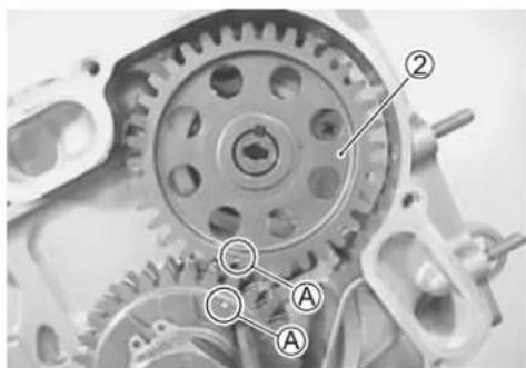

natural_image
Close-up of a mechanical gear assembly with numbered components (no visible text or symbols)- Hold the generator rotor with the special tool.

09930-44541: Rotor holder
- While holding the generator rotor, tighten the cam drive idle gear/sprocket nut to the specified torque.

Cam drive idle gear/sprocket nut:
70 N·m (7.0 kgf-m, 50.5 lb-ft)
CAUTION
Before tightening the cam drive idle gear/sprocket nut, be sure to engage the front and rear cam chains to each sprocket.
OIL SUMP FILTER
- Clean the oil sump filter using compressed air.
• Install the oil sump filter.
NOTE:
The projection Ⓐ of the oil sump filter faces to the bottom.
GEAR POSITION SWITCH
• Install the springs ① and gear position switch contacts ②.

natural_image
Close-up of a mechanical assembly with gears and a tool labeled 'TOOL' (no readable text or symbols beyond label)
natural_image
Close-up of mechanical gears and linkages in a vehicle (no visible text or symbols)
natural_image
Hand holding a diamond-shaped object with a small circular mark, against a plain background (no text or symbols visible)
natural_image
Close-up of an engine cylinder head with a labeled component (A) and circular annotation (no readable text or symbols beyond the label)
• Install the gear position switch and cable guide.
• Install the washer ① and pin ②.
• Install the oil pump driven gear by installing the snap ring.

09900-06107: Snap ring pliers
NOTE:
The boss Ⓐ of the oil pump driven gear faces crankcase side.

natural_image
Close-up of mechanical components with no visible text or symbols
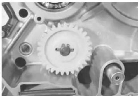
natural_image
Close-up of mechanical gears and linkages in a gear assembly (no visible text or symbols)CLUTCH
• Install the thrust washer onto the countershaft.
NOTE:
The chamfer side Ⓐ of thrust washer faces crankcase side.

natural_image
Close-up of a mechanical gear assembly with a hand adjusting a shaft (no visible text or symbols)
• Install the needle bearing ① and spacer ② onto the counter-shaft.
- Apply engine oil to them.
• Install the primary driven gear assembly ① onto the counter-shaft.
NOTE:
* When installing the primary driven gear assembly, align the teeth of the primary drive gears by inserting a suitable bar to the holes of them.
* Be sure to engage the oil pump drive and driven gears, primary drive and driven gears.
• Install the thrust washer ②.
• Install the clutch sleeve hub.
• Install the washer ③, ④ and clutch sleeve hub nut.
NOTE:
The convex side of the washer faces outside.
- Tighten the clutch sleeve hub nut to the specified torque with the special tool.

Clutch sleeve hub nut: 150 N·m (15.0 kgf·m, 108.5 lb·ft)

09920-53740: Clutch sleeve hub holder

natural_image
Mechanical assembly diagram showing gears and housing components (no text or symbols visible)
natural_image
Close-up of a mechanical gear assembly with labeled component (②), no visible text or symbols beyond the number marker.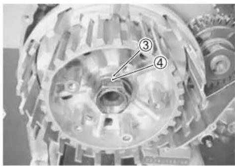
natural_image
Close-up of a mechanical gear assembly with numbered annotations (3, 4) pointing to specific components (no readable text or symbols beyond labels)

natural_image
Mechanical gear assembly with interlocking gears and a tool labeled 'TOOL' (no readable text or symbols beyond label)- Lock the clutch sleeve hub nut with a center punch.
• Install the spring washer seat ① and spring washer ② onto the clutch sleeve hub correctly.
- Insert the clutch drive plates and driven plates one by one into the clutch sleeve hub in the prescribed order, No.3 drive plate being inserted first.
NOTE:
Insert the outermost No.2 drive plate claws to the other slits of clutch housing as shown.
• Install the clutch push rod into the countershaft.
• Install the clutch push piece ③, bearing ④ and thrust washer ⑤.
- Tighten the clutch spring set bolts diagonally to the specified torque while holding the generator rotor with the special tool.

Clutch spring set bolts: 10 N·m (1.0 kgf-m, 7.0 lb-ft)

09930-44541: Rotor holder

natural_image
Close-up of a mechanical component with a central bolt and flanged shaft (no visible text or symbols)

natural_image
Close-up of a mechanical assembly with visible gears and mounting holes (no text or symbols)

natural_image
Close-up of a mechanical assembly with four circular components and gears (no visible text or symbols)
NOTE:
*The No.2 Driven plate should be installed between 4th to 7th position from the clutch sleeve hub.
*Set the numbers of driven plate to the standard specifications when replacing the driven plates with the new ones.
DRIVEN PLATE:
① No.1 Driven plate.....5 - 8 pcs. (Standard: 7pcs.)
⑥ No.2 Driven plate.....1 - 4 pcs. (Standard: 2pcs.)
DRIVE PLATE:
Ⓐ No.1 Drive plate......8 pcs.
⑧ No.2 Drive plate......1 pc.
© No.3 Drive plate......1 pc.
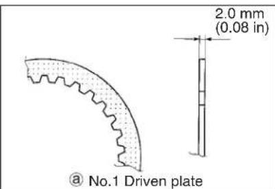


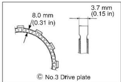
CLUTCH COVER
• Install the gasket and dowel pins.
CAUTION
Use the new gasket to prevent oil leakage.

natural_image
Mechanical assembly diagram showing gears and shafts with no visible text or symbols• Install the clutch cover.
NOTE:
Set the impeller shaft end Ⓐ to the cam drive idle shaft Ⓑ.
NOTE:
* Fit the clamp to the bolt ©.
* Install the bracket Ⓓ.
- Fit the dowel pin.
- Apply the grease to the O-ring.

99000-25030: SUZUKI SUPER GREASE "A" (USA) 99000-25010: SUZUKI SUPER GREASE "A" (Others)
• Install the water pump case.
• Install the starter idle gear ①, spacer ② and shaft ③.
NOTE:
Apply engine oil to the shaft ③.
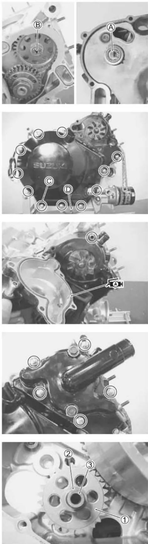
- Install the bushings Ⓐ into the crankcase and generator cover.
NOTE:
Apply molybdenum oil solution to the inside of the bushings.

MOLYBDENUM OIL
- Fit the washers onto the starter torque limiter.
• Install the starter torque limiter.
• Install the dowel pin and gasket.
CAUTION
Use the new gasket to prevent oil leakage.
• Install the generator cover.
NOTE:
Install the bracket Ⓑ.

OIL FILTER
- Apply engine oil lightly to the O-ring.
• Install the oil filter turning it by hand until feeling that the O-ring contacts the mounting surface. Then tighten it 2 turns with the special tool.

09915-40610: Oil filter wrench
• Install the cam chain.

natural_image
Close-up of mechanical components with labeled parts, no visible text or symbols
natural_image
Close-up mechanical assembly showing internal components and mounting holes (no visible text or symbols)ENGINE TOP SIDE
PISTON
• Install the piston rings in the order of oil ring, 2nd ring and 1st ring.
NOTE:
1st ring and 2nd ring differ in the shape.
- Be sure to bring the concave side of 1st ring to top when fitting it to the piston.
- 2nd (middle) ring has letters "RN" marked on the side. Be sure to bring the marked side of the 2nd ring to top when fitting it to the piston.
- The first member to go into the ring groove is spacer ①. After placing the spacer, fit the two side rails ②. Side designations, top and bottom, are not applied to the spacer and side rails: you can position each either way.
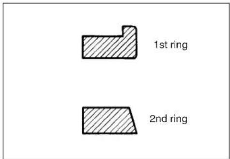
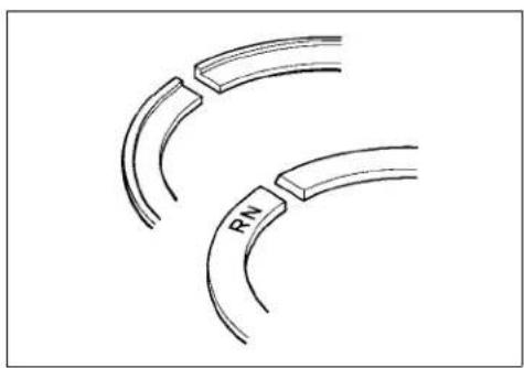
natural_image
Diagram of two curved pipe segments with a label 'RN' on one end (no other text or symbols)
- Position the gaps of the three rings as shown. Before inserting each piston into the cylinder, check that the gaps are so located.
- Apply a light coat of molybdenum oil solution to the piston pin.

MOLYBDENUM OIL
NOTE:
When installing the pistons, front and rear, the indents Ⓐ on the piston heads must be located to each exhaust side.
- Place a clean rag over the cylinder base so as not to drop the piston pin circlips into the crankcase.
• Install the pistons, front and rear.
• Install the piston pin circlips.
CAUTION
Use new piston pin circlips to prevent circlip failure which will occur with a bend one.
CAUTION
When turning the crankshaft, pull the cam chains upward, or the chains will be caught between the crankcase and the cam drive sprocket.
NOTE:
End gap of the circlip should not be aligned with the cutaway in the piston pin bore.

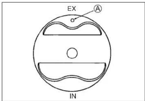

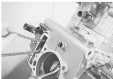
natural_image
Close-up of mechanical components including a metallic engine housing and attached cylindrical parts (no visible text or symbols)
OIL JET
- Apply engine oil to the new O-rings.
• Install each of the oil jets.
CAUTION
Use the new O-rings to prevent oil leakage.
CYLINDER
- Coat SUZUKI BOND "1215" lightly to the mating surfaces at the parting line between the right and left crankcases as shown.
NOTE:
When replacing the stud bolt Ⓐ, apply SUZUKI BOND "1215" to the thread of the crankcase side.

99000-31110: SUZUKI BOND "1215"
- Fit the dowel pins and new gaskets ① to the crankcase.
CAUTION
Use the new gaskets to prevent oil leakage.
- Apply engine oil to the sliding surface of the pistons and cylinders.
NOTE:
The cylinders can be distinguished by the embossed-letters, "F" and "R".
"F": Front (No.1) cylinder
“R”: Rear (No.2) cylinder

natural_image
Close-up of an internal combustion engine cylinder head with mounting holes and bolts (no visible text or symbols)
natural_image
Close-up of a mechanical component with a circular mark and mounting holes (no visible text or symbols)

natural_image
Two grayscale industrial machinery close-up views showing internal components and mounting features (no visible text or symbols)
- Hold the piston rings in proper position, and insert each of the pistons into the respective cylinders.
NOTE:
When installing the cylinders, keep the cam chains taut. The cam chain must not be caught between cam drive sprocket and crankcase when turning the crankshaft.
- Tighten the cylinder nuts (M6) temporarily.
NOTE:
Fit the clamp to the front cylinder nut Ⓐ.
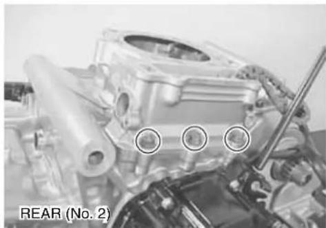
natural_image
Close-up of an internal combustion engine component with three circular annotations highlighting specific parts (no readable text or symbols)
natural_image
Close-up of a mechanical assembly with labeled components (no readable text or symbols)CYLINDER HEAD
- Pull the cam chains out of the cylinders and install the cam chain guides ①.
NOTE:
There are the guide holders for the bottom ends of each cam chain guide cast in the crankcase. Be sure that the cam chain guides are inserted properly.

natural_image
Close-up of a mechanical component with numbered annotations (1 and 2) pointing to features, no readable text or symbols present.
natural_image
Close-up of a mechanical component with numbered callouts highlighting features (no readable text or symbols)- Fit the dowel pins and new cylinder head gaskets to the cylinders, front and rear.
CAUTION
Use the new gaskets to prevent gas leakage.
- Place the rear cylinder head on the cylinder.
NOTE:
When installing the cylinder head, keep the cam chain taut.
- Tighten the cylinder head bolts (M10) to the specified two step torque with a torque wrench sequentially and diagonally.
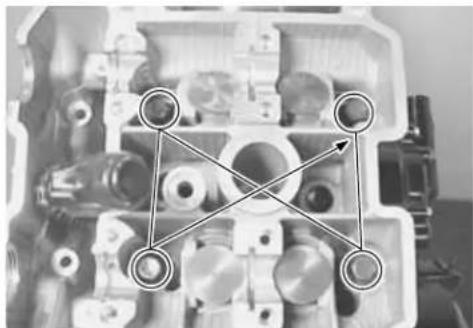
natural_image
Mechanical assembly diagram showing internal components with no visible text or symbols
Cylinder head bolt (M10):
Initial 25 N·m (2.5 kgf-m, 18.0 lb-ft)
Final 47 N·m (4.7 kgf-m, 34.0 lb-ft)
NOTE:
* Install the washers to the cylinder head bolts (M10) as shown.
* Apply engine oil to the washers and thread portion of the bolts before installing the cylinder head bolts.
• After firmly tightening the cylinder head bolts (M10), install the cylinder head nuts and bolts.
- Tighten the cylinder head nuts, bolts and the cylinder nuts.

Cylinder head nut (M8): 25 N·m (2.5 kgf-m, 18.0 lb-ft)
Cylinder head nut (M6): 10 N·m (1.0 kgf·m, 7.0 lb·ft)
Cylinder head bolt (M6): 10 N·m (1.0 kgf·m, 7.0 lb·ft)
Cylinder nut (M6): 10 N·m (1.0 kgf·m, 7.0 lb·ft)
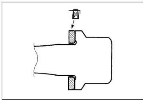
natural_image
Pure mechanical cross-section diagram without any text, numbers, or symbols
natural_image
Close-up of mechanical components with circular annotations highlighting specific parts (no readable text or symbols)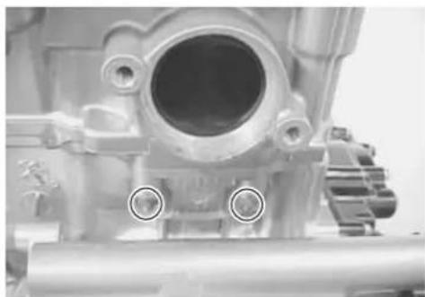
natural_image
Close-up of a mechanical component with two circular features, no visible text or symbols
natural_image
Interior view of a mechanical assembly with multiple cylindrical components and mounting holes (no visible text or labels)- Place the front cylinder head on the cylinder.
NOTE:
When installing the cylinder head, keep the cam chain taut.
- Tighten the cylinder head bolts (M10) to the specified two-step torque with a torque wrench sequentially and diagonally.

Cylinder head bolt (M10): Initial 25 N·m
(2.5 kgf-m, 18.0 lb-ft)
Final 47 N·m
(4.7 kgf-m, 34.0 lb-ft)
NOTE:
* Install the washers to the cylinder head bolts (M10) as shown.
* Apply engine oil to the washers and thread portion of the bolts before installing the cylinder head bolts.

natural_image
Close-up of a mechanical component with internal cavities and mounting holes (no visible text or symbols)
natural_image
Pure mechanical cross-section diagram without any text, numbers, or symbols• After firmly tightening the cylinder head bolts (M10), install the cylinder head nuts, bolts and oil cooler mounting bracket ①.
- Tighten the cylinder head nuts, bolts and the cylinder nuts.

natural_image
Close-up of mechanical components with circular annotations highlighting specific parts (no readable text or symbols)
Cylinder head nut (M8): 25 N·m (2.5 kgf-m, 18.0 lb-ft) Cylinder head nut (M6): 10 N·m (1.0 kgf-m, 7.0 lb-ft) Cylinder head bolt (M6): 10 N·m (1.0 kgf-m, 7.0 lb-ft) Cylinder nut (M6): 10 N·m (1.0 kgf-m, 7.0 lb-ft)

natural_image
Mechanical assembly diagram showing internal components with no visible text or symbols
natural_image
Cross-sectional view of a mechanical assembly showing internal components and housing (no visible text or labels)- Pull the cam chains upward and install the cam chain tensioners into each cylinder head.
① For No.1 (Front) cylinder head
② For No.2 (Rear) cylinder head

natural_image
Two black metal tools with labeled parts, no visible text or symbolsNOTE:
* When installing the cam chain tensioners, insert the their holder ends Ⓐ into each guide cast on the cylinder.
* When installing the No.1 (Front) cam chain tensioner, through it rear side of the rib Ⓑ.

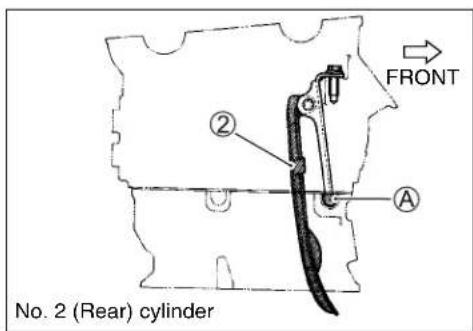
- Tighten the cam chain tensioner mounting bolts to the specified torque.

Cam chain tensioner mounting bolt:
10 N·m (1.0 kgf-m, 7.0 lb-ft)
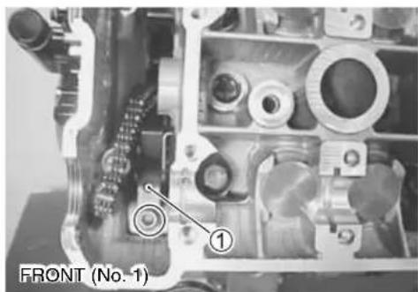

natural_image
Interior view of a mechanical assembly with labeled parts (no readable text or symbols)FRONT CAM DRIVE IDLE GEAR/SPROCKET
- Turn the crankshaft counterclockwise with the box wrench and align "F I T" line Ⓐ on the generator rotor with the index mark Ⓑ of the valve timing inspection hole while keeping the camshaft drive chain pulled upward.
CAUTION
Pull the cam chains upward, or the chain will be caught between crankcase and cam drive sprocket.
CAUTION
To adjust the camshaft timing correctly, be sure to align "F I T" line Ⓐ with the index mark Ⓑ and hold this position when installing the cam drive idle gears/sprockets, front and rear.
- Apply molybdenum oil solution to the cam drive idle gear/sprocket bearing, its shaft ①, and thrust washer ②.

MOLYBDENUM OIL
NOTE:
* The thickness of thrust washer ② must be selected for each cylinder head. THRUST WASHER SELECTION ☐ 3-44
* Paint the engraved line © on the cam drive idle gear/sprocket.
• Install the cam drive idle gear/sprocket onto the front cylinder head and engage the cam chain on it.
- Align the engraved line © on the cam drive idle gear/sprocket with the embossed line Ⓓ on the cylinder head.
• Install the cam drive idle gear/sprocket shaft ①, the copper washer ③ and the thrust washer ②.

natural_image
Close-up of a mechanical assembly with gears and components, no visible text or symbols

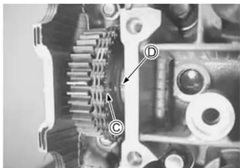
natural_image
Close-up of mechanical components with labeled parts (C, D) and no readable text or symbols beyond labels
- Check and correct the positions of the "F I T" line on the generator rotor and cam drive idle gear/sprocket ①.
CAUTION
When checking the positions, remove the cam chain slack at the cam chain guide ② side by holding the cam drive idle gear/sprocket by hand.
NOTE:
Due to special valve train mechanism, aligning of the three elements; the engraved line Ⓐ, embossed line Ⓑ and the gear tooth root on the cam drive idle gear/sprocket; can occur once every other rotation of crankshaft.

natural_image
Close-up of mechanical gear and housing components, showing teeth and a circular head (no text or symbols visible)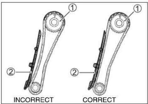
CAUTION
If the engraved line Ⓐ does not align the embossed line Ⓑ, turn the crankshaft 360° (1 turn) to bring the "F | T" line on the generator rotor to the index mark of the valve timing inspection hole again and reinstall the cam drive idle gear/sprocket to the correct position as shown.

CAUTION
Pull the cam chains upward, or the chain will be caught between crankcase and cam drive sprocket when turning the crankshaft.

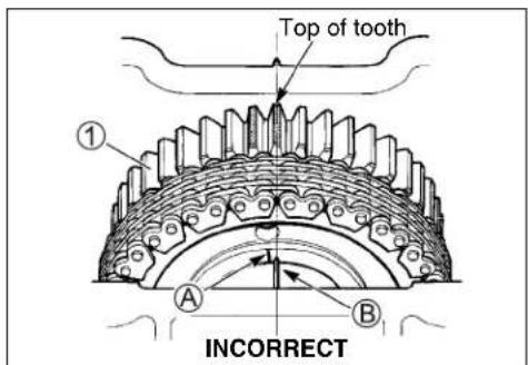
NOTE:
When checking the cam drive idle gear/sprocket ① position at its gear tooth, top or root, bring the eye level as shown in right illustration.
- Tighten the cam drive idle gear/sprocket shaft to the specified torque.

Cam drive idle gear/sprocket shaft:
40 N·m (4.0 kgf-m, 29.0 lb-ft)
CAM CHAIN TENSION ADJUSTER
• Install the front cam chain tension adjuster to the following procedure.
NOTE:
The cam chain tension adjusters are distinguished by the shapes.
① For No.1 (Front) cylinder
② For No.2 (Rear) cylinder
- Turn in the cam chain tension adjuster bolt ③ fully.


natural_image
Close-up of a mechanical gear assembly with no visible text or symbols
natural_image
Two mechanical components with numbered labels (① and ②) showing different assembly states (no text or symbols on the parts themselves)
natural_image
Close-up of a mechanical screw component with threaded shaft and flange (no visible text or symbols)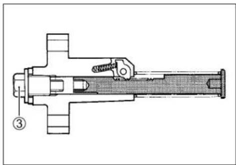
natural_image
Technical line drawing of a mechanical assembly with no visible text or symbols- Compress the cam chain tension adjuster rod ① fully by releasing the ratchet②.


- From this position, turn out the cam chain tension adjuster bolt ③ until locking the cam chain tension adjuster rod ①. Now the cam chain tension adjuster is ready to install.

NOTE: Turn out the cam chain tension adjuster bolt ③ while compressing the cam chain tension adjuster rod.

• Install the new gasket④.
CAUTION
Use the new gasket to prevent oil leakage.
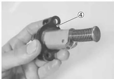
natural_image
Close-up of a hand holding a metallic mechanical component with threaded end (no visible text or symbols)• Install the cam chain tension adjuster as shown and tighten its mounting bolts to the specified torque.
Cam chain tension adjuster mounting bolt:
10 N·m (1.0 kgf-m, 7.0 lb-ft)
- Release the cam chain tension adjuster by turning in its bolt ①.
NOTE:
Click sound is heard when the cam chain tension adjuster rod is released.
- Tighten the cam chain tension adjuster bolt ① to the specified torque.
Cam chain tension adjuster bolt (Front):
23 N·m (2.3 kgf-m, 16.5 lb-ft)
CAUTION
After installing the cam chain tension adjuster, check to be sure that the adjuster work properly by checking the slack of cam chain.
REAR CAM DRIVE IDLE GEAR/SPROCKET
- For the rear cam drive idle gear/sprocket installation, the crankshaft setting position must be set at the same position (TDC of compression stroke) as the front one.
- The procedures are also the same as the front cam drive idle gear/sprocket installation.
CAUTION
When checking the cam drive idle gear/sprocket position, remove the cam chain slack at the cam chain guide ② side by holding it by hand.

natural_image
Close-up mechanical assembly showing internal components and gears (no visible text or symbols)
natural_image
Close-up mechanical assembly showing gears and shafts in a vehicle (no visible text or symbols)
natural_image
Technical cross-sectional diagram of a mechanical assembly (no text or labels visible)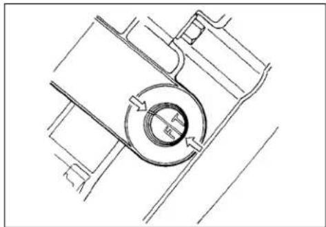
natural_image
Technical line drawing of a mechanical component with a circular feature and directional arrows (no text or symbols)
REAR CAM CHAIN TENSION ADJUSTER
• Install the rear cam chain tension adjuster to the following procedure.
- Disassemble the rear cam chain tension adjuster.
- Compress the cam chain tension adjuster rod by releasing the ratchet.
• Install the new gasket①.
CAUTION
Use the new gasket to prevent oil leakage.
• Install the cam chain tension adjuster as shown and tighten its mounting bolts to the specified torque.

Cam chain tension adjuster mounting bolt:
10 N·m (1.0 kgf-m, 7.0 lb-ft)
• Install a new O-ring, spring and cam chain tension adjuster bolts and tighten them to the specified torque.
NOTE:
Apply grease to the O-ring before installing.

99000-25030: SUZUKI SUPER GREASE "A" (USA)
99000-25010: SUZUKI SUPER GREASE "A" (Others)

Cam chain tension adjuster bolt (Rear):
7 N·m (0.7 kgf-m, 5.0 lb-ft)
NOTE:
Click sound is heard when extending the cam chain tension adjuster rod.
CAUTION
After installing the cam chain tension adjuster, check to be sure that the adjuster work properly by checking the slack of cam chain.

natural_image
Mechanical assembly components including a spring, bolt, and valve (no text or symbols visible)
natural_image
Close-up of a hand holding a metallic mechanical component with two arrows indicating direction (no text or symbols visible)
natural_image
Close-up of a hand holding a metallic ring with a numbered label pointing to the ring (no text or symbols on the ring itself)
natural_image
Close-up of a mechanical assembly with two circular annotations highlighting specific components (no readable text or symbols)
natural_image
Close-up of a mechanical assembly with a finger inserted into a component, no visible text or symbolsCAMSHAFT
- Rotate the generator rotor 720 degrees (2 turns) and align the "F I T" line on the generator rotor with the index mark of the valve timing inspection hole.
- Recheck the position of the engraved lines Ⓐ on the front and rear cam drive idle gears/sprockets.
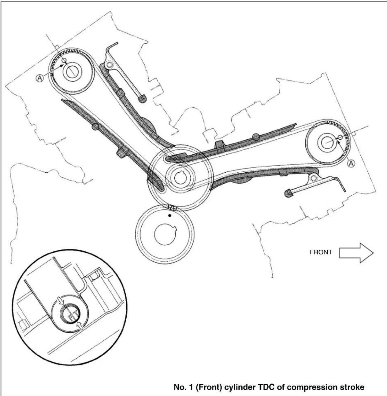
NO.1 (FRONT) CAMSHAFTS
- At the above condition, install the No.1 (Front) camshafts, intake and exhaust, in the following procedure.
NOTE:
The cam shafts are identified by the engraved letters.
① No.1 (Front) exhaust camshaft
② No.1 (Front) intake camshaft
③ No.2 (Rear) exhaust camshaft
④ No.2 (Rear) intake camshaft
NOTE:
Before placing the camshafts on cylinder head, apply molybdenum oil solution to their journals and cam faces.
Apply engine oil to the camshaft journal holders.

MOLYBDENUM OIL
- Place the No.1 (front) camshafts, intake and exhaust.
- Align the engraved lines Ⓐ on the camshafts so it is parallel with the mating surface of the cylinder head cover. Check that the cam faces are located as shown.
• Install the dowel pins.
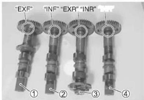
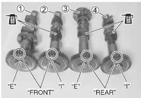


natural_image
Cross-sectional view of a mechanical transmission gear assembly (no visible text or labels)• Install the camshaft journal holders, intake and exhaust.
- Fasten the camshaft journal holders evenly by tightening the camshaft journal holder bolts sequentially and diagonally. (Try to equalize the pressure by shifting the wrench in the above manner, to fasten the shafts evenly.)
NOTE:
* Damage to head or camshaft journal holder thrust surfaces may result if the camshaft journal holders are not drawn down evenly.
* Each camshaft journal holder is identified with a cast-on letters Ⓐ.
- Tighten the camshaft journal holder bolts to the specified torque.
Camshaft journal holder bolt: 10 N·m (1.0 kgf·m, 7.0 lb·ft)
CAUTION
The camshaft journal holder bolts are made of a special material and much superior in strength, compared with other types of high strength bolts.
Take special care not to use other types of bolts instead of these special bolts. To identify these bolts, each of them has a figure "9" on its head.
- Recheck the No.1 (Front) camshaft positions, intake and exhaust.

natural_image
Mechanical assembly diagram showing gears and housing components with labeled points A (no text or symbols beyond labels)
• Install the No.2 (Rear) camshafts, intake and exhaust, in the following procedure.
- From the position where the No.1 (Front) camshafts have now been installed, rotate the generator rotor 360 degrees (1 turn) and align the "F I T" line on the generator rotor with the index mark of the valve timing inspection hole.
NOTE:
At this position, the engraved line Ⓐ on the cam drive idle gear/sprocket is inside the cylinder head and not visible.

natural_image
Close-up of a mechanical engine component with a circular symbol labeled 'F T' and an arrow pointing to a specific part (no readable text or symbols beyond the label)
- Place the No.2 (Rear) camshafts, intake ① and exhaust ②.
- Align the engraved lines Ⓑ on the camshafts so that it is parallel with mating surface of the cylinder head cover. Check that the cam faces are located as shown.


• Install the dowel pins.
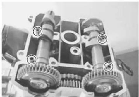
natural_image
Close-up of a mechanical gear assembly with multiple teeth and central bore (no visible text or symbols)• Install the camshaft journal holders, intake and exhaust.
- Fasten the camshaft journal holders evenly by tightening the camshaft journal holder bolts sequentially and diagonally. (Try to equalize the pressure by shifting the wrench in the above manner, to fasten the shafts evenly.)
NOTE:
* Damage to head or camshaft journal holder thrust surfaces may result if the camshaft journal holders are not drawn down evenly.
* Each camshaft journal holder is identified with a cast-on letter Ⓐ.
- Tighten the camshaft journal holder bolts to the specified torque.

Camshaft journal holder bolt: 10 N·m (1.0 kgf·m, 7.0 lb·ft)
CAUTION
The camshaft journal holder bolts are made of a special material and much superior in strength, compared with other types of high strength bolts.
Take special care not to use other types of bolts instead of these special bolts. To identify these bolts, each of them has a figure "9" on its head.
- Recheck the No.2 (Rear) camshaft positions, intake and exhaust.

• After installing the No.2 (Rear) camshafts, rotate the generator rotor 360 degrees (1 turn), and recheck the positions of the camshafts.
CAUTION
Be sure to check the positions of the "F | T" line Ⓐ on the generator rotor, engraved line Ⓑ on the cam drive idle gears/sprockets and the engraved line Ⓒ on the camshafts.
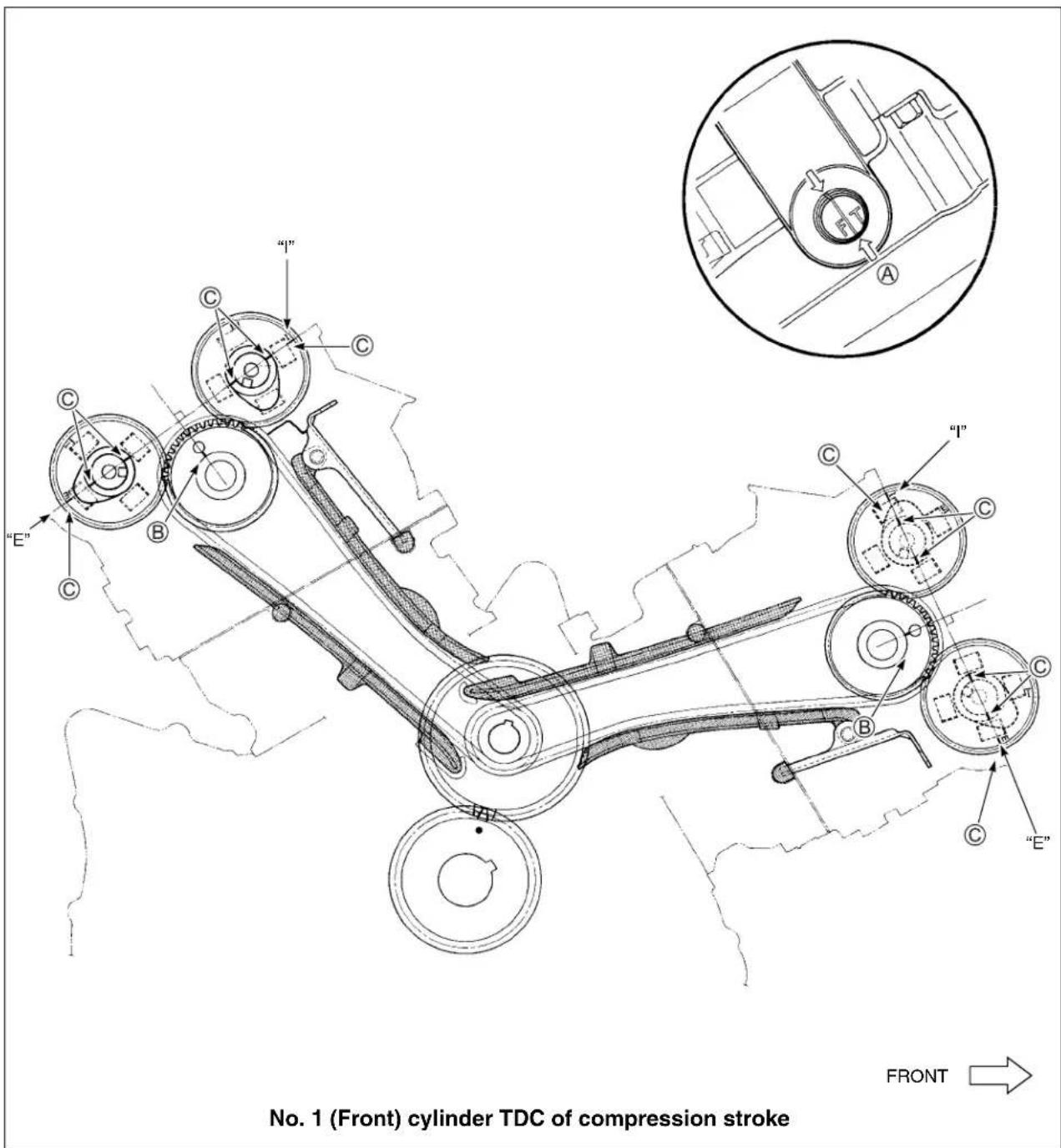
- Pour engine oil in each oil pocket in the front and rear cylinder heads.
CAUTION
Be sure to check the tappet clearance.
CYLINDER HEAD COVER
• Install the new gaskets (②, ③) to each cylinder head cover.
- Apply SUZUKI BOND "1207B" to the cam end caps of the gaskets as shown.

99000-31140: SUZUKI BOND "1207B"
CAUTION
Use the new gaskets to prevent oil leakage.
- Place the cylinder head covers on each cylinder head.
- Fit the gaskets to each head cover bolt.
CAUTION
Use the new gaskets to prevent oil leakage.
• After applying engine oil to the gaskets, tighten the head cover bolts to the specified torque.

Head cover bolt: 14 N·m (1.4 kgf-m, 10.0 lb-ft)
SPARK PLUG
• Install the spark plugs.

09930-10121: Spark plug wrench set
• Install the valve timing inspection plug ①.

natural_image
Close-up of a mechanical engine component with labeled parts (no readable text or symbols)
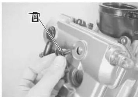
natural_image
Close-up of a mechanical component being adjusted with a tool (no visible text or symbols)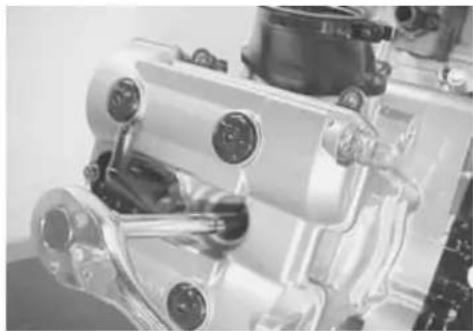
natural_image
Close-up of a mechanical assembly with metallic components and bolts (no visible text or symbols)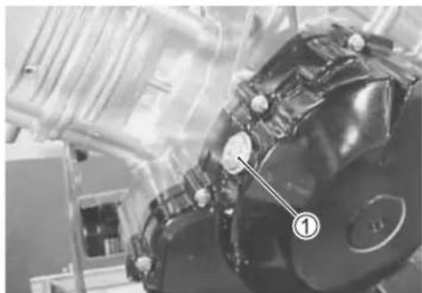
natural_image
Close-up of a mechanical component with numbered annotation (1) and no visible text or symbols- Apply engine oil to the new O-ring and install the generator cover plug.
CAUTION
Use the new O-ring to prevent oil leakage.
STARTER MOTOR
• Install the new O-ring to the starter motor.
CAUTION
Use the new O-ring to prevent oil leakage.
- Apply grease to the O-ring.

99000-25030: SUZUKI SUPER GREASE "A" (USA)
99000-25010: SUZUKI SUPER GREASE "A" (Others)
• Install the starter motor.
NOTE:
Fit the clamp to the bolt Ⓐ.
• Install the thermostat case.

natural_image
Close-up of a hand holding a mechanical component with a close-up view of its internal structure (no visible text or symbols)
natural_image
Close-up of mechanical components with no visible text or symbols
natural_image
Mechanical assembly diagram showing a rotating component with labeled points A and O (no text or symbols beyond labels)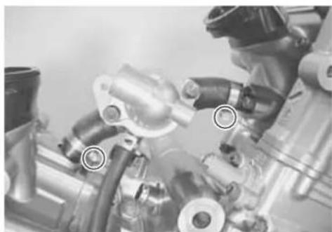
natural_image
Close-up of mechanical components with no visible text or symbolsFI SYSTEM
CONTENTS
PRECAUTIONS IN SERVICING 4-2
CONNECTOR/COUPLER 4-2
FUSE 4-3
ECM/VARIOUS SENSORS 4-3
ELECTRICAL CIRCUIT INSPECTION PROCEDURE 4-5
USING TESTERS 4-8
FI SYSTEM TECHNICAL FEATURES 4-9
INJECTION TIME (INJECTION VOLUME) 4-9
COMPENSATION OF INJECTION TIME (VOLUME) 4-10
INJECTION STOP CONTROL 4-10
INJECTION TIMING 4-15
SENSORS 4-16
FAIL-SAFE FUNCTION 4-26
FI SYSTEM TROUBLESHOOTING 4-27
CUSTOMER COMPLAINT ANALYSIS 4-27
SELF-DIAGNOSTIC PROCEDURES 4-29
SELF-DIAGNOSIS RESET PROCEDURE 4-29
MALFUNCTION CODE AND DEFECTIVE CONDITION 4-30
"C11" CMP SENSOR CIRCUIT MALFUNCTION 4-32
"C12" CKP SENSOR CIRCUIT MALFUNCTION 4-33
"C13" IAP SENSOR CIRCUIT MALFUNCTION 4-34
"C14" TP SENSOR CIRCUIT MALFUNCTION 4-36
"C15" ECT SENSOR CIRCUIT MALFUNCTION 4-38
"C21" IAT SENSOR CIRCUIT MALFUNCTION 4-39
"C22" AP SENSOR CIRCUIT MALFUNCTION 4-40
"C23" TO SENSOR CIRCUIT MALFUNCTION 4-42
"C24" or "C25" IGNITION SYSTEM MALFUNCTION 4-43
"C28" STV ACTUATOR CIRCUIT MALFUNCTION 4-43
"C29" STP SENSOR CIRCUIT MALFUNCTION 4-44
"C31" GEAR POSITION (GP) SWITCH CIRCUIT MALFUNCTION .....4-46
"C32" or "C33" FUEL INJECTION MALFUNCTION 4-47
"C41" FP RELAY CIRCUIT MALFUNCTION 4-48
"C42" IG SWITCH CIRCUIT MALFUNCTION 4-48
"C44" HO₂ SENSOR (HO₂S) CIRCUIT MALFUNCTION 4-49
FUEL SYSTEM 4-51
FUEL TANK LIFT-UP 4-51
FUEL TANK REMOVAL 4-52
FUEL TANK INSTALLATION 4-52
FUEL PRESSURE INSPECTION 4-53
FUEL PUMP INSPECTION 4-54
FUEL PUMP RELAY INSPECTION 4-55
FUEL PUMP AND FUEL FILTER REMOVAL 4-55
FUEL MESH FILTER INSPECTION AND CLEANING 4-57
FUEL PUMP AND FUEL MESH FILTER INSTALLATION 4-57
THROTTLE BODY AND STV ACTUATOR 4-59
CONSTRUCTION 4-59
THROTTLE BODY REMOVAL 4-60
THROTTLE BODY DISASSEMBLY 4-61
THROTTLE BODY CLEANING 4-65
INSPECTION 4-65
THROTTLE BODY REASSEMBLY 4-65
STP SENSOR ADJUSTMENT 4-68
THROTTLE BODY INSTALLATION 4-69
TP SENSOR ADJUSTMENT 4-69
FUEL INJECTOR INSPECTION 4-69
FUEL INJECTOR REMOVAL 4-70
FUEL INJECTOR INSTALLATION 4-70
FAST IDLE INSPECTION 4-70
FAST IDLE ADJUTMENT 4-71
THROTTLE VALVE SYNCHRONIZATION 4-72
THROTTLE CABLE ADJUSTMENT 4-73
SENSOR 4-74
IAP SENSOR INSPECTION 4-74
IAP SENSOR REMOVAL/INSTALLATION 4-74
TP SENSOR INSPECTION 4-74
TP SENSOR REMOVAL/INSTALLATION 4-74
STP SENSOR INSPECTION 4-74
STP SENSOR REMOVAL/INSTALLATION 4-74
CKP SENSOR INSPECTION 4-75
CKP SENSOR REMOVAL/INSTALLATION 4-75
CMP SENSOR INSPECTION 4-75
CMP SENSOR REMOVAL/INSTALLATION 4-75
IAT SENSOR INSPECTION 4-75
IAT SENSOR REMOVAL/INSTALLATION 4-75
ECT SENSOR INSPECTION 4-76
ECT SENSOR REMOVAL/INSTALLATION 4-76
AP SENSOR INSPECTION 4-76
AP SENSOR REMOVAL/INSTALLATION 4-76
TO SENSOR INSPECTION 4-76
TO SENSOR REMOVAL/INSTALLATION 4-76
HO2 SENSOR INSPECTION ....4-76
HO2 SENSOR REMOVAL/INSTALLATION ....4-77
PRECAUTIONS IN SERVICING
When handling the FI component parts or servicing the FI system, observe the following points for the safety of the system.
CONNECTOR/COUPLER
- When connecting a connector, be sure to push it in until a click is felt.
- With a lock type coupler, be sure to release the lock when disconnecting, and push it in fully till the lock works when connecting it.
- When disconnecting the coupler, be sure to hold the coupler body and do not pull the lead wires.
- Inspect each terminal on the connector/coupler for looseness or bending.
- Inspect each terminal for corrosion and contamination. The terminals must be clean and free of any foreign material which could impede proper terminal contact.
- Inspect each lead wire circuit for poor connection by shaking it by hand lightly. If any abnormal condition is found, repair or replace.
- When taking measurements at electrical connectors using a tester probe, be sure to insert the probe from the wire harness side (backside) of the connector/coupler.
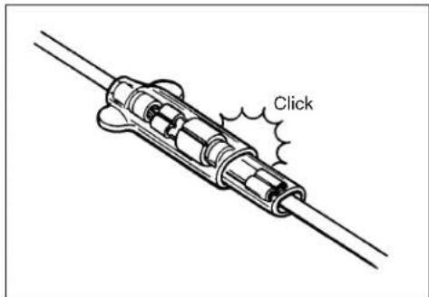

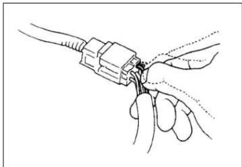
natural_image
Line drawing of hands connecting a cable to a connector (no text or symbols present)
- When connecting meter probe from the terminal side of the coupler (connection from harness side not being possible), use extra care not to force and cause the male terminal to bend or the female terminal to open.
Connect the probe as shown to avoid opening of female terminal.
Never push in the probe where male terminal is supposed to fit.
- Check the male connector for bend and female connector for excessive opening. Also check the coupler for locking (loose-ness), corrosion, dust, etc.
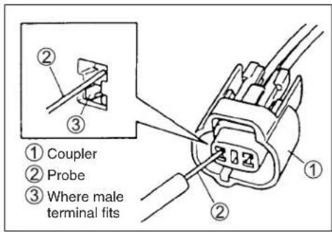
FUSE
- When a fuse blows, always investigate the cause, correct it and then replace the fuse.
- Do not use a fuse of a different capacity.
- Do not use wire or any other substitute for the fuse.

natural_image
Line drawing of a small electronic component with a curved internal line and top marking (no text or symbols)ECM/VARIOUS SENSORS
- Since each component is a high-precision part, great care should be taken not to apply any sharp impacts during removal and installation.
- Be careful not to touch the electrical terminals of the ECM. The static electricity from your body may damage this part.

natural_image
Line drawing of a hand inserting a USB into a device housing (no text or symbols)- When disconnecting and connecting the ECM couplers, make sure to turn OFF the ignition switch, or electronic parts may get damaged.
- Battery connection in reverse polarity is strictly prohibited. Such a wrong connection will damage the components of the FI system instantly when reverse power is applied.
- Removing any battery terminal of a running engine is strictly prohibited. The moment such removal is made, damaging counter electromotive force will be applied to the ECM which may result in serious damage.
- Before measuring voltage at each terminal, check to make sure that battery voltage is 11 V or higher. Terminal voltage check at low battery voltage will lead to erroneous diagnosis.
- Never connect any tester (voltmeter, ohmmeter, or whatever) to the ECM when its coupler is disconnected. Otherwise, damage to ECM may result. - Never connect an ohmmeter to the ECM with its coupler connected. If attempted, damage to ECM or sensors may result. - Be sure to use a specified voltmeter/ohmmeter. Otherwise, accurate measurements may not be obtained and personal injury may result.


natural_image
Line drawing of a battery with two wires and a fuse, showing a lightning bolt striking the fuse (no text or symbols present)
ELECTRICAL CIRCUIT INSPECTION PROCEDURE
While there are various methods for electrical circuit inspection, described here is a general method to check for open and short circuit using an ohmmeter and a voltmeter.
OPEN CIRCUIT CHECK
Possible causes for the open circuit are as follows. As the cause can exist in the connector/coupler or terminal, they need to be checked carefully.
- Loose connection of connector/coupler
- Poor contact of terminal (due to dirt, corrosion or rust, poor contact tension, entry of foreign object etc.)
- Wire harness being open
- Poor terminal-to-wire connection
- Disconnect the negative cable from the battery.
- Check each connector/coupler at both ends of the circuit being checked for loose connection. Also check for condition of the coupler lock if equipped.
- Using a test male terminal, check the female terminals of the circuit being checked for contact tension.
Check each terminal visually for poor contact (possibly caused by dirt, corrosion, rust, entry of foreign object, etc.). At the same time, check to make sure that each terminal is fully inserted in the coupler and locked.
If contact tension is not enough, rectify the contact to increase tension or replace.
The terminals must be clean and free of any foreign material which could impede proper terminal contact.
- Using continuity inspect or voltage check procedure as described below, inspect the wire harness terminals for open circuit and poor connection. Locate abnormality, if any.


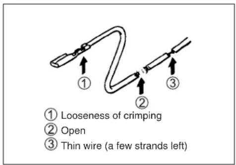
Continuity check
- Measure resistance across coupler Ⓑ (between Ⓐ and Ⓒ in the figure). If no continuity is indicated (infinity or over limit), the circuit is open between terminals Ⓐ and Ⓑ.
- Disconnect the coupler Ⓑ and measure resistance between couplers Ⓐ and Ⓑ. If no continuity is indicated, the circuit is open between couplers Ⓐ and Ⓑ. If continuity is indicated, there is an open circuit between couplers Ⓑ' and Ⓒ or an abnormality in coupler Ⓑ' or coupler Ⓒ.
VOLTAGE CHECK
If voltage is supplied to the circuit being checked, voltage check can be used as circuit check.
- With all connectors/couplers connected and voltage applied to the circuit being checked, measure voltage between each terminal and body ground.
If measurements were taken as shown in the figure at the right and results are as listed below, it means that the circuit is open between terminals Ⓐ and Ⓑ.
Voltage Between:
© and body ground: Approx. 5V
⑧ and body ground: Approx. 5V
Ⓐ and body ground: 0V
Also, if measured values are as listed below, a resistance (abnormality) exists which causes the voltage drop in the circuit between terminals A and B.
Voltage Between:
© and body ground: Approx. 5V
⑧ and body ground: Approx. 5V —— 2V voltage drop
Ⓐ and body ground:


SHORT CIRCUIT CHECK (WIRE HARNESS TO GROUND)
- Disconnect the negative cable from the battery.
- Disconnect the connectors/couplers at both ends of the circuit to be checked.
NOTE:
If the circuit to be checked branches to other parts as shown, disconnect all connectors/couplers of those parts. Otherwise, diagnosis will be misled.
- Measure resistance between terminal at one end of circuit ( A terminal in figure) and body ground. If continuity is indicated, there is a short circuit to ground between terminals A and C.

- Disconnect the connector/coupler included in circuit (coupler ⑧) and measure resistance between terminal ⑨ and body ground.
If continuity is indicated, the circuit is shorted to the ground between terminals Ⓐ and Ⓑ.

USING TESTERS
- Use the Suzuki multi-circuit tester (09900-25008).
- Use well-charged batteries in the tester.
- Be sure to set the tester to the correct testing range.
Using the tester
- Incorrectly connecting the and probes may cause the inside of the tester to burnout.
- If the voltage and current are not known, make measurements using the highest range.
- When measuring the resistance with the multi-circuit tester, ∞ will be shown as 10.00MΩ and "1" flashes in the display.
- Check that no voltage is applied before making the measurement. If voltage is applied, the tester may be damaged.
• After using the tester, turn the power off.

09900-25008: Multi-circuit tester
NOTE:
* When connecting the multi-circuit tester, use a fine needle pointed probe or install fine copper wires (O.D is below 0.5 mm) to the back side of the lead wire coupler and connect the probes of tester to them.
* Use a fine copper wire, the outer diameter being below 0.5 mm, to prevent the rubber of the water proof coupler from damage.
MULTI-CIRCUIT TESTER

FI SYSTEM TECHNICAL FEATURES INJECTION TIME (INJECTION VOLUME)
The factors to determine the injection time include the basic fuel injection time which is calculated on the basis of the intake air pressure, engine speed and throttle opening angle, and various compensations. These compensations are determined according to the signals from various sensors that detect the engine and driving conditions.

flowchart
graph LR
    A["Intake Air Pressure Sensor (IAP Sensor)"] --> B["Intake air pressure signal"]
    C["Crankshaft Position Sensor (CKP Sensor)"] --> D["Engine speed signal"]
    E["Throttle Position Sensor (TP Sensor)"] --> F["Throttle opening signal"]
    G["Various Sensors"] --> H["Various signals"]
    I["Injectors"] --> J["Injection signal"]
    B --> K["Basic fuel injection time"]
    D --> K
    F --> K
    H --> L["Compensation"]
    J --> M["Ultimate fuel injection time"]
    K --> M
    L --> M
    M --> N["ECM"]
COMPENSATION OF INJECTION TIME (VOLUME)
The following different signals are output from the respective sensors for compensation of the fuel injection time (volume).
| SIGNAL DESCRIPTION | |
| ATMOSPHERIC PRESSURE SENSOR SIGNAL | When atmospheric pressure is low, the sensor sends the signal to the ECM and reduce the injection time (volume). |
| ENGINE OIL TEMPERATURE SENSOR SIGNAL | When engine oil temperature is low, injection time (volume) is increased. |
| INTAKE AIR TEMPERATURE SENSOR SIGNAL | When intake air temperature is low, injection time (volume) is increased. |
| BATTERY VOLTAGE SIGNAL ECM operates | on the battery voltage and at the same time, it monitors the voltage signal for compensation of the fuel injection time (volume). A longer injection time is needed to adjust injection volume in the case of low voltage. |
| ENGINE RPM SIGNAL At high speed, the injection time (volume) is increased. | |
| STARTING SIGNAL When starting engine, additional fuel is injected during cranking engine. | |
| ACCELERATION SIGNAL/DECELERATION SIGNAL | During acceleration, the fuel injection time (volume) is increased, in accordance with the throttle opening speed and engine rpm. During deceleration, the fuel injection time (volume) is decreased. |
INJECTION STOP CONTROL
| SIGNAL DESCRIPTION | |
| TIP OVER SENSOR SIGNAL(FUEL SHUT-OFF) | When the motorcycle tips over, the tip over sensor sends a signal to the ECM. Then, this signal cuts OFF current supplied to the fuel pump, fuel injectors and ignition coils. |
| OVER-REV. LIMITER SIGNAL The fuel injectors stop operation when engine rpm reaches rev. limit rpm. | |
The fuel delivery system consists of the fuel tank, fuel pump, fuel filters, fuel feed hose, fuel delivery pipe (including fuel injectors) and fuel pressure regulator. There is no fuel return hose. The fuel in the fuel tank is pumped up by the fuel pump and pressurized fuel flows into the injector installed in the fuel delivery pipe. Fuel pressure is regulated by the fuel pressure regulator. As the fuel pressure applied to the fuel injector (the fuel pressure in the fuel delivery pipe) is always kept at absolute fuel pressure of 300 kPa (3.0 kgf/cm -2 , 43 psi), the fuel is injected into the throttle body in conic dispersion when the injector opens according to the injection signal from the ECM.
The fuel relieved by the fuel pressure regulator flows back to the fuel tank.

FUEL PUMP
The electric fuel pump is mounted at the bottom of the fuel tank, which consists of the armature, magnet, impeller, brush, check valve and relief valve. The ECM controls its ON/OFF operation as controlled under the FUEL PUMP CONTROL SYSTEM.
When electrical energy is supplied to the fuel pump, the motor in the pump runs and together with the impeller. This causes a pressure difference to occur on both sides of the impeller as there are many grooves around it. Then the fuel is drawn through the inlet port, and with its pressure increased, it is discharged through the outlet port. The fuel pump has a check valve to keep some pressure in the fuel feed hose even when the fuel pump is stopped. Also, the relief valve is equipped in the fuel pump, which releases pressurized fuel to the fuel tank when the outlet of the fuel pressure has increased up to 450 – 600 kPa (4.5 – 6.0 kgf/cm², 64 – 85 psi).

When the impeller is driven by the motor, pressure differential occurs between the front part and the rear part of the blade groove as viewed in angular direction due to fluid friction. This process continuously takes place causing fuel pressure to be built up. The pressurized fuel is then let out from the pump chamber and discharged through the motor section and the check valve.

FUEL PRESSURE REGULATOR
The fuel pressure regulator consists of the spring and valve. It keeps absolute fuel pressure of 300 kPa (3.0 kgf/cm 2 , 43 psi) to be applied to the injector at all times.
When the fuel pressure rises more than 300 kPa (3.0 kgf/cm 2 , 43 psi), the fuel pushes the valve in the regulator open and excess fuel returns to the fuel tank.
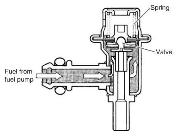

FUEL INJECTOR
The fuel injector consists of the solenoid coil, plunger, needle valve and filter.
It is an electromagnetic type injection nozzle which injects fuel in the throttle body according to the signal from the ECM.
When the solenoid coil of the injector is energized by the ECM, it becomes an electromagnet and attracts the plunger. At the same time, the needle valve incorporated with the plunger opens and the injector which is under the fuel pressure injects fuel in conic dispersion. As the lift stroke of the needle valve of the injector is set constant, the volume of the fuel injected at one time is determined by the length of time during which the solenoid coil is energized (injection time).

When the ignition switch is turned on, current from the battery flows to the fuel pump motor through the side-stand relay and the fuel pump relay causing the motor to turn.
Since the ECM has a timer function, the fuel pump motor stops turning in three seconds after the switch has been turned on.
Thereafter, when the crankshaft is turned by the starter motor or the engine has been started, the engine revolving signal is input to the ECM. Then, current flows to the fuel pump motor from the battery through the side-stand relay and the fuel pump relay so that the pump continues to function.
A tip over sensor is provided in the fuel pump control circuit. By this provision, anytime the motorcycle tips over, the tip over sensor sends a signal to the ECM to turn off power to the fuel pump relay, causing the fuel pump motor to stop. At the same time, current to the fuel injectors as well as the ignition coil is interrupted, which then stops the engine.

ECM (FI CONTROL UNIT)
The ECM is located under the seat.
The ECM consists of CPU (Central Processing Unit), memory (ROM) and I/O (Input/Output) sections. The signal from each sensor is sent to the input section and then sent to CPU. On the basis of signal information received, CPU calculates the volume of fuel necessary for injection using maps programmed for varying engine conditions. Then, the operation signal of the fuel injection is sent from the output section to the fuel injector.
The eight kinds of independent program maps are programmed in the ROM.
These eight kinds of maps are designed to compensate for differences of the intake/exhaust systems and cooling performance.
LIGHT LOAD: When the engine is running in a light load, the fuel injected volume (time) is determined the on basis of the intake air pressure and engine speed.
HEAVY LOAD: When the engine is running in a heavy load, the fuel injected volume (time) is determined on the basis of the throttle valve opening and engine speed.

natural_image
Interior view of a vehicle battery pack with visible circuit breakers and wiring (no text or symbols)INJECTION TIMING
The system employs a sequential, front-and-rear-cylinder independent injection type, using the crankshaft position sensor (signal generator) to determine the piston position (injection timing and ignition timing) and the camshaft position sensor to identify the cylinder during operation, and these information are sent to the ECM. This makes it possible to inject the optimum volume of fuel in the best timing for the engine operating conditions.
SENSORS
INTAKE AIR PRESSURE SENSOR (IAP SENSOR)
The intake air pressure sensor is located at the rear side of the air cleaner box and its vacuum hose is connected to the throttle body.
The sensor detects the intake air pressure, which is then converted into voltage signal and sent to the ECM.
The basic fuel injection time (volume) is determined according to the voltage signal (output voltage).
The voltage signal increases when the intake air pressure is high.
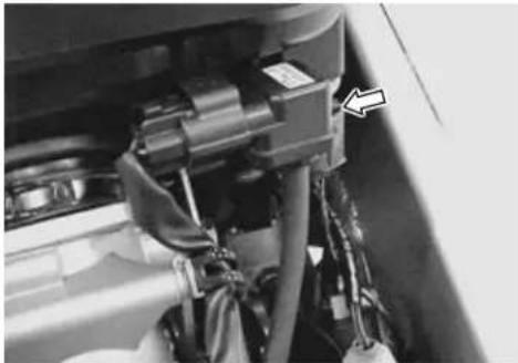
natural_image
Close-up of a mechanical assembly with visible wiring and components, no text or symbols present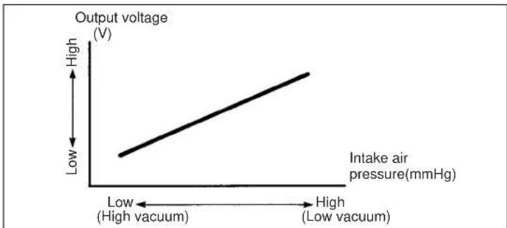
line
| Intake air pressure(mmHg) | Output voltage (V) | | ------------------------- | ------------------ | | Low | Low | | High | High |THROTTLE POSITION SENSOR (TP SENSOR)
The throttle position sensor is installed on the No.1 throttle body. The throttle position sensor is a kind of variable resistor which detects the throttle opening angle.
The battery voltage in the sensor is changed to the throttle position voltage which is then sent to the ECM.
The basic fuel injection time (volume) is determined according to the voltage signal (output voltage).
The voltage signal increases as the throttle is opened wider.

natural_image
Close-up of mechanical components with a white arrow pointing to a component (no visible text or symbols)
line
| Throttle valve opening(Degree) | Output voltage (V) | | ------------------------------ | ------------------ | | Small | Low | | Large | High |CRANKSHAFT POSITION SENSOR (CKP SENSOR)
The signal rotor is mounted on the left end of the crankshaft, and the crankshaft position sensor (Pick-up coil) is installed in the generator cover.
The sensor generates the pick-up signal to be supplied to the ECM.
The ECM calculates and decides both the fuel injection timing and ignition timing.
The injection volume increases when the engine rpm is high.
CAMSHAFT POSITION SENSOR (CMP SENSOR)
The signal rotor is installed on the No.2 intake camshaft, and the camshaft position sensor (Pick-up coil) is installed on the No.2 cylinder head cover.
The sensor generates the pick-up signal to be supplied to the ECM.
The ECM calculates and decides the cylinder identity and sequential injection timing.

natural_image
Close-up of a mechanical clutch assembly with visible gears and housing (no text or symbols)
natural_image
Close-up of a mechanical component with a highlighted connector (no visible text or symbols)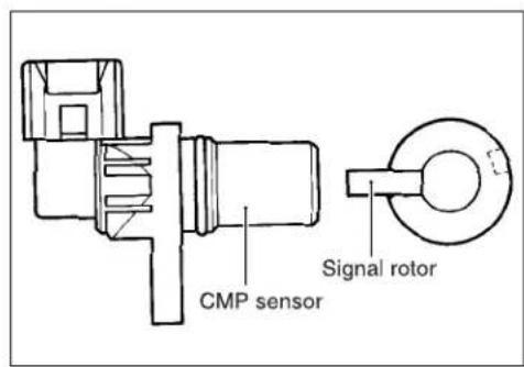
INTAKE AIR TEMPERATURE SENSOR (IAT SENSOR)
The intake air temperature sensor is installed at the rear side of the air cleaner box.
The sensor detects the intake air temperature in thermistor resistance value. With this resistance value converted to voltage signal, the signal is sent to the ECM. The injection volume increases as intake air temperature decreases.
The thermistor resistance value increases when the intake air temperature is low, and decreases when the intake air temperature is high.

natural_image
Close-up of mechanical components with no visible text or symbols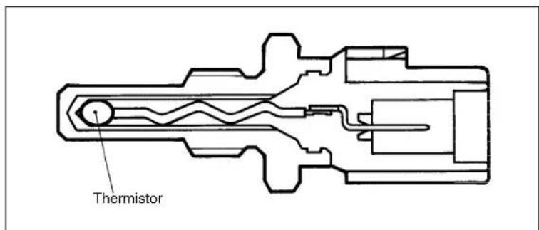
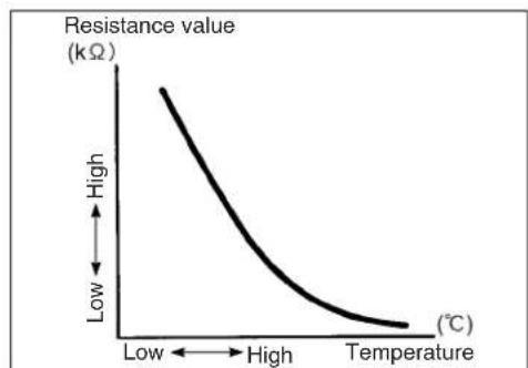
line
| Temperature (°C) | Resistance value (kΩ) | | ---------------- | --------------------- | | Low | High | | High | Low |ENGINE COOLANT TEMPERATURE SENSOR (ECT SENSOR)
The engine coolant temperature sensor is installed at the thermostat case.
The sensor detects the engine oil temperature in thermistor resistance value, which is then converted to voltage signal and sent to the ECM. The injection volume increases as oil temperature decreases.
The thermistor resistance value increases when the engine oil temperature is low, and decreases when the engine oil temperature is high.

natural_image
Close-up of a mechanical assembly with hoses and connectors, no visible text or symbols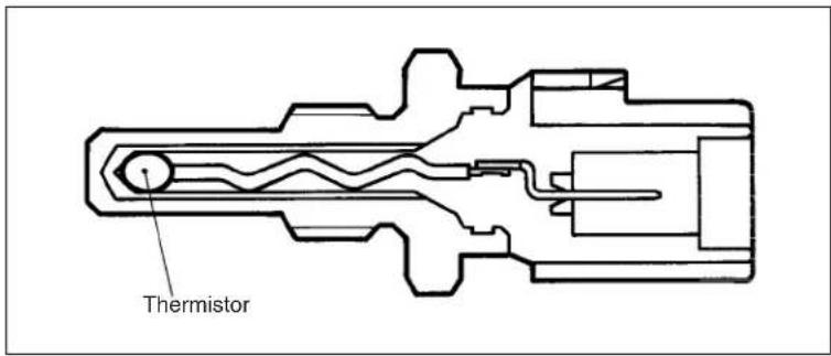

line
| Temperature (°C) | Resistance value (kΩ) | | ---------------- | --------------------- | | Low | High | | High | Low |ATMOSPHERIC PRESSURE SENSOR (AP SENSOR)
The atmospheric pressure sensor is located under the seat. The sensor detects the atmospheric pressure. The detected pressure is converted into voltage signal and sent to the ECM. The injection time (volume) is controlled according to the voltage signal (output voltage).
The voltage signal increases as the atmospheric pressure rises.

natural_image
Close-up of mechanical components with a white arrow pointing to a specific part (no visible text or symbols)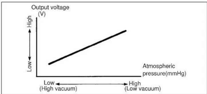
line
| Pressure (mmHg) | Output voltage (V) | |---|---| | Low | High | | High | Low |TIP OVER SENSOR (TO SENSOR)
The tip over sensor is located above the AP sensor.
The sensor detects the leaning of the motorcycle. When it leans more than 65irc , the mechanical switch turns ON and a signal is sent to the ECM. At the same time, this signal cuts OFF current supply to the fuel pump, fuel injectors and ignition coils.
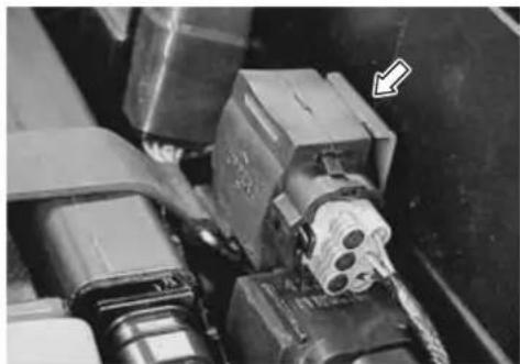
natural_image
Close-up of mechanical components with a white arrow pointing to a component (no visible text or symbols)
SECONDARY THROTTLE POSITION SENSOR (STP SEN- SOR)
The secondary throttle position sensor is installed on the No.1 throttle body.
The secondary throttle position sensor is a kind of variable resistor which detects the secondary throttle opening angle.
The STP sensor detects the STV actuator movement by the voltage signal which is then sent to the ECM.
The ECM determines the ST valve angle based on the operation map.
The voltage signal increases as the secondary throttle is opened wider.

natural_image
Close-up of mechanical components with a white arrow pointing to a component (no visible text or symbols)
line
| Throttle valve opening (Degree) | Output voltage (V) | |---|---| | Small | Low | | Large | High |A Speedometer
B Secondary throttle position sensor (STPS)
© Throttle position sensor (TPS)
D Secondary throttle valve actuator (STVA)
E Tip over sensor (TOS)
⑤ Fuel pump relay (FP RELAY)
© Atomospheric pressure sensor (APS)
H Crankshaft position sensor (CKPS)
① Speed sensor
① Fuel pump (FP)
© Ignition coil (IG COIL)

L Intake air temperature sensor (IATS)
M Intake air pressure sensor (IAPS)
© Camshaft position sensor (CMPS)
Engine coolant temperature sensor (ECTS)
© Gear position switch
@ Heated oxygen sensor (HO₂S)
® PAIR solenoid valve
⑤ Fuel injector (FI)
FI SYSTEM WIRING DIAGRAM
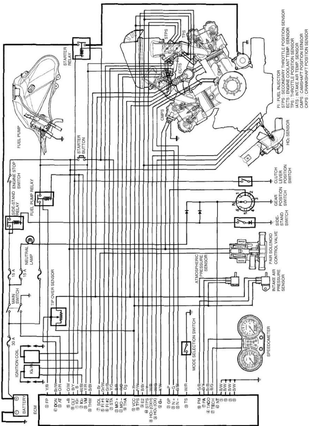
flowchart
graph TD
    subgraph Power Supply
        direction TB
        A["BATTERY"] --> B["IGNITION COIL"]
        B --> C["MAIN SWITCH"]
        C --> D["NEUTRAL LAMP"]
        D --> E["SIDE-STAND RELAY"]
        E --> F["ENGINE STOP SWITCH"]
        F --> G["FUEL PUMP"]
        G --> H["STARTER RELAY"]
        H --> I["STPTS"]
        I --> J["HO2 SENSOR"]
    end

    subgraph Control Systems
        direction LR
        K["TIP OVER SENSOR"] --> L["MODE SELECTION SWITCH"]
        L --> M["ATMOSPHERIC PRESSURE SENSOR"]
        M --> N["PAIR SOLENOID CONTROL VALVE"]
        N --> O["SIDE-STAND SWITCH"]
        O --> P["GEAR POSITION SWITCH"]
        P --> Q["CLUTCH LEVER POSITION SWITCH"]
        Q --> R["HO2 SENSOR"]

    end

    subgraph Control Components
        direction LR
        S["FUEL PUMP"] --> T["STARTER BUTTON"]
        T --> U["STPTS"]
        U --> V["HO2 SENSOR"]

    end

    subgraph Power Supply
        direction LR
        W["ECM"] --> X["FP"]
        X --> Y["DON"]
        Y --> Z["AT"]
        Z --> AA["+B"]
        AA --> AB["CLT"]
        AB --> AC["IG1"]
        AC --> AD["IG2"]
        AD --> AE["VM"]
        AE --> AF["THW"]
        AF --> AG["SOL"]
        AG --> AH["FI #1"]
        AH --> AI["FI #2"]
        AI --> AJ["STA"]
        AJ --> AK["MO +"]
        AK --> AL["MO -"]
        AL --> AM["THA"]
        AM --> AN["VCC"]
        AN --> AO["TPS"]
        AO --> AP["E2"]
        AP --> AQ["STPS"]
        AQ --> AR["HO2 (OXH)"]
        AR --> AS["HO2 (OX)"]
        AS --> AT["G+"]
        AT --> AU["GP"]
        AU --> AV["N +"]
        AV --> AW["N -"]
        AW --> AX["TS"]
        AX --> AY["PM"]
        AY --> AZ["PA"]
        AZ --> BA["TACO"]
        BA --> BB["TECH"]
        BB --> BC["NT"]
        BC --> BD["B/W"]
        BD --> BE["B/W"]
        BE --> BF["B/W"]
        BF --> BG["B/W"]

    end

    style Power Supply fill:#f9f,stroke:#333
    style Control Components fill:#ccf,stroke:#333
SELF-DIAGNOSIS FUNCTION
The self-diagnosis function is incorporated in the ECM. The function has two modes, "User mode" and "Dealer mode". The user can only be notified by the LCD (DISPLAY) panel and LED (FI light). To check the function of the individual FI system devices, the dealer mode is prepared. In this check, the special tool is necessary to read the code of the malfunction items.
USER MODE
| MALFUNCTION | LCD (DISPLAY) INDICATION | FI LIGHT INDICATION | INDICATION MODE |
| “NO” Odometer —— | |||
| “YES”Engine can start | Odometer and “FI” letters *1 | FI light turns ON. Each | 2 sec. Odometer or “FI” is indicated. |
| Engine can not start | “FI” letters *2 | FI light turns ON and blinks. | “FI” is indicated continuously. |
*1
When one of the signals is not received by ECM, the fail-safe circuit works and injection is not stopped. In this case, "FI" and odometer are indicated in the LCD panel and motorcycle can run.
*2
The injection signal is stopped, when the crankshaft position sensor signal, tip over sensor signal, #1/#2 ignition signals, #1/#2 injector signals, fuel pump relay signal or ignition switch signal is not sent to ECM. In this case, "FI" is indicated in the LCD panel. Motorcycle does not run.
“CHEC”: The LCD panel indicates “CHEC” when no communication signal from the ECM is received for 3 seconds.
For Example:
The ignition switch is turned ON, and the engine stop switch is turned OFF. In this case, the speedometer does not receive any signal from the ECM, and the panel indicates "CHEC".
If CHEC is indicated, the LCD does not indicate the trouble code. It is necessary to check the wiring harness between ECM and speedometer couplers.
The possible cause of this indication is as follows;
Engine stop switch is in OFF position. Side-stand/ignition inter-lock system is not working. Ignition fuse is burnt.
DEALER MODE
The defective function is memorized in the computer. Use the special tool's coupler to connect to the dealer mode coupler. The memorized malfunction code is displayed on LCD (DISPLAY) panel. Malfunction means that the ECM does not receive signal from the devices. These affected devices are indicated in the code form.

09930-82710: Mode select switch
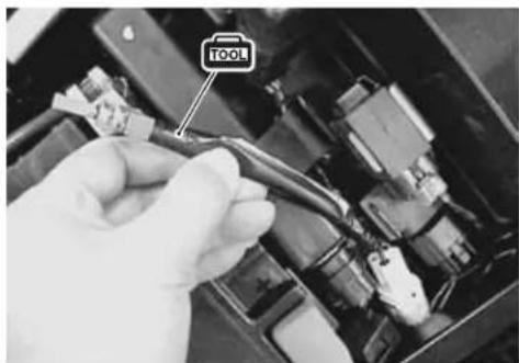


CAUTION
Before checking the malfunction code, do not disconnect the ECM lead wire couplers. If the couplers from the ECM are disconnected, the malfunction code memory is erased and the malfunction code can not be checked.
| MALFUNCTION | LCD (DISPLAY) INDICATION | FI LIGHT INDICATION INDICATION MODE | |
| “NO” C00 | FI light turns OFF. | — | |
| “YES” | C** code is indicated from small numeral to large one. | For each 2 sec., code is indicated. | |
| CODE | MALFUNCTION PART REMARKS | ||
| C00 | None | No defective part | |
| C11 | Camshaft position sensor (CMPS) | ||
| C12 | Crankshaft position sensor (CKPS) | Pick-up coil signal, signal generator | |
| C13 | Intake air pressure sensor (IAPS) | ||
| C14 | Throttle position sensor (TPS) | ||
| C15 | Engine coolant temp. sensor (ECTS) | ||
| C21 | Intake air temp. sensor (IATS) | ||
| C22 | Atmospheric pressure sensor (APS) | ||
| C23 | Tip over sensor (TOS) | ||
| C24 | Ignition signal #1 (IG coil #1) | For #1 cylinder | |
| C25 | Ignition signal #2 (IG coil #2) | For #2 cylinder | |
| C28 | Secondary throttle valve actuator (STVA) | *3 | |
| C29 | Secondary throttle position sensor (STPS) | ||
| C31 | Gear position signal (GP switch) | ||
| C32 | Injector signal #1 (FI #1) | For #1 cylinder | |
| C33 | Injector signal #2 (F1 #2) | For #2 cylinder | |
| C41 | Fuel pump control system (FP control system) | Fuel pump, Fuel pump relay | |
| C42 | Ignition switch signal (IG switch signal) | Anti-theft | |
| C44 | Heated oxygen sensor ( HO2S ) | ||
| CODE | MALFUNCTION PART REMARKS | |
| C00 | None | No defective part |
| C11 | Camshaft position sensor (CMPS) | |
| C12 | Crankshaft position sensor (CKPS) | Pick-up coil signal, signal generator |
| C13 | Intake air pressure sensor (IAPS) | |
| C14 | Throttle position sensor (TPS) | |
| C15 | Engine coolant temp. sensor (ECTS) | |
| C21 | Intake air temp. sensor (IATS) | |
| C22 | Atmospheric pressure sensor (APS) | |
| C23 | Tip over sensor (TOS) | |
| C24 | Ignition signal #1 (IG coil #1) | For #1 cylinder |
| C25 | Ignition signal #2 (IG coil #2) | For #2 cylinder |
| C28 | Secondary throttle valve actuator (STVA) | *3 |
| C29 | Secondary throttle position sensor (STPS) | |
| C31 | Gear position signal (GP switch) | |
| C32 | Injector signal #1 (FI #1) | For #1 cylinder |
| C33 | Injector signal #2 (F1 #2) | For #2 cylinder |
| C41 | Fuel pump control system (FP control system) | Fuel pump, Fuel pump relay |
| C42 | Ignition switch signal (IG switch signal) | Anti-theft |
| C44 | Heated oxygen sensor ( HO2S ) |
In the LCD (DISPLAY) panel, the malfunction code is indicated from small code to large code. *3 When the secondary throttle valve actuator and secondary throttle position sensor signals are not sent to ECM, C29 is indicated.
TPS ADJUSTMENT
- Adjust the engine rpm to 1 200 ± 100 rpm. (2-14)
- Stop the engine and connect the special tool (Mode select switch) to the dealer mode coupler at the wiring harness.
- If the throttle position sensor adjustment is necessary, loosen the screws and turn the throttle position sensor and bring the line to middle.
- Then, tighten the screws to fix the throttle position sensor.

09930-11950: Torx wrench

The LCD indicates 0.4 sec./time. The correct position must be determined when the middle line is indicated twice or more, where the sensor should be fixed.

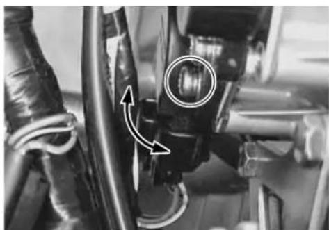
natural_image
Close-up of mechanical components with curved arrows indicating motion or movement (no visible text or symbols)
CD indicates 0.4 sec./time.

correct position must be deterr

ted twice or more, where the
ted twice of more, where the
[Non-Text]
[Non-Text]
[Non-Text]
[Non-Text]
[Non-Text]
[Non-Text]
[Non-Text]
[Non-Text]
[Non-Text]
[Non-Text]
[Non-Text]
[Non-Text]
[Non-Text]
[Non-Text]
[Non-Text]

•

(2)

The Ground Truth image displays a single, solid horizontal line. According to Rule 2 (UNDERSCORE & LINE RULES), this is a stylistic or background line, not a placeholder underscore. Therefore, the OCR result must ignore it and output nothing or only meaningful text. The provided OCR content is "____", which consists of four underscores. This is an incorrect interpretation of the line as a placeholder, violating the rule that stylistic lines must be ignored. The OCR has hallucinated placeholder underscores where none should exist in the GT. Hence, the OCR result is inconsistent with the Ground Truth.

[Non-Text]

[Non-Text]

[Non-Text]

[Non-Text]

[Non-Text]

[Non-Text]

[Non-Text]

[Non-Text]

[Non-Text]

[Non-Text]

[Non-Text]

[Non-Text]

[Non-Text]

[Non-Text]

[Non-Text]

[Non-Text]

[Non-Text]

[Non-Text]

[Non-Text]

[Non-Text]

[Non-Text]

[Non-Text]

[Non-Text]

[Non-Text]

[Non-Text]

[Non-Text]

[Non-Text]

[Non-Text]

[Non-Text]

[Non-Text]

[Non-Text]

[Non-Text]

[Non-Text]

[Non-Text]

[Non-Text]

FAIL-SAFE FUNCTION
FI system is provided with fail-safe function to allow the engine to start and the motorcycle to run in a minimum performance necessary even under malfunction condition.
| ITEM FAIL-SAFE | MODE STARTING ABILITY | RUNNING ABILITY | ||
| Intake air pressure sensor | Intake air pressure is fixed to 760 mmHg. | “YES” “YES” | ||
| Throttle position sensor The | throttle opening is fixed to full open position. Ignition timing is also fixed. | “YES” “YES” | ||
| Engine coolant temperature sensor | Engine coolant temperature value is fixed to 80°C. | “YES” “YES” | ||
| Intake air temperature sensor | Intake air temperature value is fixed to 40°C. | “YES” “YES” | ||
| Atmospheric pressure sensor | Atmospheric pressure is fixed to 760 mmHg. | “YES” “YES” | ||
| Ignition signal #1 #1 | Ignition-off | “YES” “YES” | ||
| #2 cylinder can run. | ||||
| Ignition-off | “YES” “YES” | |||
| #1 cylinder can run. | ||||
| Injection signal #1 #1 | Fuel-cut | “YES” “YES” | ||
| #2 cylinder can run. | ||||
| Fuel-cut | “YES” “YES” | |||
| #1 cylinder can run. | ||||
| Secondary throttle valve actuator | Secondary throttle valve is fixed to half open position. | “YES” “YES” | ||
| Secondary throttle position sensor | Secondary throttle valve is fixed to half open position. | “YES” “YES” | ||
| Gear position signal Gear position signal is fixed to 6th gear. | “YES” “YES” | |||
| Heated oxygen sensor Fuel-air compensation ratio is fixed to normal condition. | “YES” “YES” | |||
“Yes” means that the engine can start and can run even if the above signal is not received from each sensor. But, the engine running condition is not complete, providing only emergency help (by fail-safe circuit). In this case, it is necessary to bring the motorcycle to the workshop for complete repair.
FI SYSTEM TROUBLESHOOTING CUSTOMER COMPLAINT ANALYSIS
Record details of the problem (failure, complaint) and how it occurred as described by the customer. For this purpose, use of such an inspection form will facilitate collecting information to the point required for proper analysis and diagnosis.
EXAMPLE: CUSTOMER PROBLEM INSPECTION FORM
| User name: Model: VIN: | |||
| Date of issue: Date Reg. Date of problem: Mileage: | |||
| Malfunction indicator lamp condition (LED) | □Always ON Sometimes ON Always OFF Good condition |
| Malfunction display/code (LCD) | User mode: □No display Malfunction display ( ) |
| Dealer mode: □No code Malfunction code ( ) |
| PROBLEM SYMPTOMS | |
| ☐Difficult Starting Poor Driveability ☐No cranking Hesitation on acceleration ☐No initial combustion ☐Back fire/ After fire☐ No combustion Lack of power ☐Poor starting at ☐ Surging(□ cold warm always) ☐ Abnormal knocking☐ Other ____ ☐ Other ____ | |
| ☐ Poor Idling ☐ Engine Stall when☐ Poor fast Idle ☐ Immediately after start☐ Abnormal idling speed ☐ Throttle valve is opened(□ High Low) ( r/min) ☐ Throttle valve is closed☐ Unstable ☐ Load is applied☐ Hunting ( r/min. to r/min) ☐ Other ____ | |
| ☐ OTHERS: | |
| MOTORCYCLE/ENVIRONMENTAL CONDITION WHEN PROBLEM OCCURS | |
| Environmental condition | |
| WeatherTemperatureFrequencyRoad Urban Suburb Highway Mountainous ( Uphill Downhill) □ □Tarmacadam Gravel Other | |
| Motorcycle condition | |
| Engine condition | Cold Warming up phase Warmed up Always Other at startingImmediately after start Racing without load Engine speed ( r/min) |
| Motorcycle condition | During driving: Constant speed Accelerating DeceleratingRight hand corner Left hand corner When shifting (Gear position )At stop Motorcycle speed when problem occurs ( km/h, Mile/h)Other |
NOTE:
The above form is a standard sample. It should be modified according to conditions characteristic of each market.
SELF-DIAGNOSTIC PROCEDURES
- Don't disconnect couplers from ECM, battery cable from battery, ECM ground wire harness from engine or main fuse before confirming malfunction code (self-diagnostic trouble code) stored in memory. Such disconnection will erase memorized information in ECM memory.
- Malfunction code stored in ECM memory can be checked by the special tool.
- Before checking malfunction code, read SELF-DIAGNOSIS FUNCTION "USER MODE and DEALER MODE" (4-23, -24 and -25) carefully to have good understanding as to what functions are available and how to use it.
- Be sure to read "PRECAUTIONS for Electrical Circuit Service" (4-5) before inspection and observe what is written there.
- Remove the seat.
- Connect the special tool to the dealer mode coupler Ⓐ at the wiring harness, and start the engine or crank the engine for more than 4 seconds.
- Turn the special tool's switch ON and check the malfunction code to determine the malfunction part.

09930-82710: Mode select switch
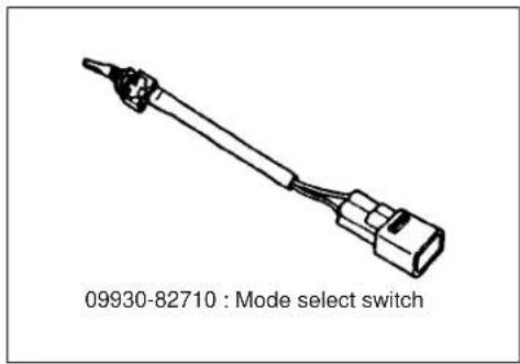


SELF-DIAGNOSIS RESET PROCEDURE
• After repairing the trouble, turn OFF the ignition switch and turn ON again.
- If the malfunction code indicates (C00), the malfunction is cleared.
- Disconnect the special tool from the dealer mode coupler.

MALFUNCTION CODE AND DEFECTIVE CONDITION
| MALFUNCTION CODE | DETECTED ITEM | DETECTED FAILURE CONDITIONCHECK FOR |
| C00 NO FAULT | —— | |
| C11 | Camshaft position sensor | The signal does not reach ECM for more than 3 sec. after receiving the starter signal.The camshaft position sensor wiring and mechanical parts.(Camshaft position sensor, intake cam pin, wiring/coupler connection) |
| C12 | Crankshaft position sensor | The signal does not reach ECM for more than 3 sec. after receiving the starter signal.The crankshaft position sensor wiring and mechanical parts.(Crankshaft position sensor, wiring/coupler connection) |
| C13 | Intake air pressure sensor | The sensor should produce following voltage.(0.10 V sensor voltage < 4.80 V)Without the above range, C13 is indicated.Intake air pressure sensor, wiring/coupler connection. |
| C14 | Throttle position sensor | The sensor should produce following voltage.(0.10 V sensor voltage < 4.80 V)Without the above range, C14 is indicated.Throttle position sensor, wiring/coupler connection. |
| C15 | Engine coolant temperature sensor | The sensor voltage should be the following.(0.10 V sensor voltage < 4.60 V)Without the above range, C15 is indicated.Engine coolant temperature sensor, wiring/coupler connection. |
| C21 | Intake air temperature sensor | The sensor voltage should be the following.(0.10 V sensor voltage < 4.60 V)Without the above range, C21 is indicated.Intake air temperature sensor, wiring/coupler connection. |
| C22 | Atmospheric pressure sensor | The sensor voltage should be the following.(0.10 V sensor voltage < 4.80 V)Without the above range, C22 is indicated.Atm. pressure sensor, wiring/coupler connection. |
| C23 | Tip over sensor The sensor | Sensor voltage should be less than the following for more than 4 sec. after ignition switch turns ON.(0.20 V sensor voltage < 4.60 V)Without the above value, C23 is indicated.Tip over sensor, wiring/coupler connection. |
| C24 or C25 | Ignition signal Crankshaft | Position sensor (pick-up coil) signal is produced but signal from ignition coil is interrupted continuous by two times or more. In this case, the code C24 or C25 is indicated.Ignition coil, wiring/coupler connection, power supply from the battery. |
| C28 | Secondary throttle valve actuator | When no actuator control signal is supplied from the ECM or communication signal does not reach ECM or operation voltage does not reach STVA motor, C28 is indicated. STVA can not operate.STVA lead wire/coupler. |
| C29 | Secondary throttle position sensor | The sensor should produce following voltage.(0.10 V sensor voltage < 4.80 V)Without the above range, C29 is indicated.Secondary throttle position sensor, wiring/coupler connection. |
| C31 | Gear position signal Gear position signal voltage should be higher than the following for more than 4 seconds.(Gear position switch voltage > 1.0 V)Without the above value, C31 is indicated.Gear position sensor, wiring/coupler connection. Gearshift cam etc. | |
| C32 or C33 | Fuel injector signal When fuel injection signal stops, the C32 or C33 is indicated.Injector, wiring/coupler connection, power supply to the injector. | |
| C41 | Fuel pump relay signal When no signal is supplied from fuel pump relay, C41 is indicated.Fuel pump relay, connecting lead, power source to fuel pump relay. | |
| C42 | Ignition switch signal Ignition switch signal is not input in the ECM.Ignition switch, lead wire/coupler. | |
| C44 | Heated oxygen sensor (HO2S) | The sensor voltage should be less than the following after warming up condition.(Sensor voltage < 0.4 V)Without the above value, C44 is indicated.Heater operation voltage does not reach in the oxygen heater circuit, C44 in indicated.The Heater can not operate.HO2S lead wire/coupler connection.Battery voltage supply to the HO2S. |
"C11" CMP SENSOR CIRCUIT MALFUNCTION
| DETECTED CONDITION POSSIBLE CAUSE | |
| No CMP sensor signal for 3 seconds at engine cranking. | • Metal particles or foreign material being attached on the CMP sensor and rotor tip.• CMP sensor circuit open or short.• CMP sensor malfunction.• ECM malfunction. |
INSPECTION
- Lift and support the fuel tank with its prop stay. (4-51)

Turn the ignition switch OFF.
Check the CMP sensor coupler for loose or poor contacts. If OK, then measure the CMP sensor peak voltage. Insert the copper wires to the CMP sensor coupler and crank the engine a few seconds or start the engine, and measure the peak voltage.

CMP sensor peak voltage: More than 3.7 V
(⊕Y/W - ⊖B/W)

09900-25008: Multi circuit tester

Tester knob indication: Voltage (--)

flowchart
graph TD
    A["Yes"] --> B["No"]
    B --> C["Replace the CMP sensor with a new one."]

Remove the CMP sensor.
If the metal particles or foreign material is attached on the CMP sensor and rotor tip, signal not flow correctly to the ECM. Clean the CMP sensor and rotor tip with a spray-type carburetor cleaner and blow dry with compressed air and also change the engine oil if necessary.

flowchart
graph TD
    A["No"] --> B["Loose or poor contacts on the CMP sensor coupler or ECM coupler."]
    B --> C["Replace the CMPsensor with a new one."]
    D["Yes"] --> A
O/W, Y/W or B/W wire open or shorted to ground, or poor ⑫, ⑮ or ⑳ connection. (4-22)
If wire and connection are OK, intermittent trouble or faulty ECM.
Recheck each terminal and wire harness for open circuit and poor connection. (4-5)


natural_image
Close-up of a mechanical assembly with visible components and a white arrow pointing to a component (no text or symbols)


natural_image
Close-up of a black mechanical component with cylindrical and stepped features (no visible text or symbols)
"C12" CKP SENSOR CIRCUIT MALFUNCTION
| DETECTED CONDITION POSSIBLE CAUSE | |
| No CKP sensor signal for 3 seconds at engine cranking. | • Metal particles or foreign material being attached on the CKP sensor and rotor tip.• CKP sensor circuit open or short.• CKP sensor malfunction.• ECM malfunction. |
INSPECTION
- Remove the left frame cover. (6-5)

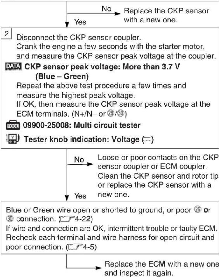
flowchart
graph TD
    A["No"] --> B["Replace the CKP sensor with a new one."]
    C["Yes"] --> B
    D["Disconnect the CKP sensor coupler.<br>Crank the engine a few seconds with the starter motor,<br>and measure the CKP sensor peak voltage at the coupler."] --> E["DATA CKP sensor peak voltage: More than 3.7 V (Blue - Green)<br>Repeat the above test procedure a few times and<br>measure the highest peak voltage.<br>If OK, then measure the CKP sensor peak voltage at the<br>ECM terminals. (N+/N- or 26/30)"]
    F["09900-25008: Multi circuit tester"] --> G["Tester knob indication: Voltage (---)"]
    H["No"] --> I["Loose or poor contacts on the CKP sensor coupler or ECM coupler.<br>Clean the CKP sensor and rotor tips<br>or replace the CKP sensor with a new one."]
    I --> J["Yes"]
    K["Blue or Green wire open or shorted to ground, or poor 26 or 30 connection. (4-22)<br>If wire and connection are OK, intermittent trouble or faulty ECM.<br>Recheck each terminal and wire harness for open circuit and<br>poor connection. (4-5)"]
    L["Replace the ECM with a new one and inspect it again."] --> M["-->"]
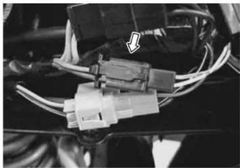
natural_image
Close-up of automotive electrical connectors with wires and a white arrow pointing to a component (no visible text or symbols)


"C13" IAP SENSOR CIRCUIT MALFUNCTION
| DETECTED CONDITION POSSIBLE CAUSE | |
| Low pressure and low voltage.High pressure and high voltage. ( 0.10 V Sensor voltage & < 4.80 V \\ without the above range. ) NOTE:Note that atmospheric pressure caries depending on weather conditions as well as altitude.Take that into consideration when inspecting voltage. | Clogged vacuum passage between throttle body and IAP sensor.Air being drawn from vacuum passage between throttle body and IAP sensor.Red wire circuit open or shorted to ground.B/Br or G/B wire circuit shorted to ground.IAP sensor malfunction.ECM malfunction. |
INSPECTION
- Lift and support the fuel tank with its prop stay. (4-51)
1 Turn the ignition switch OFF. Check the IAP sensor coupler for loose or poor contacts. If OK, then measure the IAP sensor input voltage. Disconnect the IAP sensor coupler. Turn the ignition switch ON. Measure the voltage at the Red wire and ground. If OK, then measure the voltage at the Red wire and B/Br wire.
DATA IAP sensor input voltage: 4.5 – 5.5 V (⊕Red) - ⊖Ground (⊕Red) - ⊖B/Br
09900-25008: Multi circuit tester Tester knob indication: Voltage (—)


natural_image
Close-up of mechanical components with a directional arrow pointing to a component (no visible text or symbols)
2 Connect the IAP sensor coupler. Insert the copper wires to the lead wire coupler. Start the engine at idling speed. Measure the IAP sensor output voltage at the wire side coupler (between G/B and B/Br wires).
DATA IAP sensor output voltage: Approx. 2.5 V at idle speed ( G/B - B/Br ) 09900-25008: Multi circuit tester Tester knob indication: Voltage (---)
No Check the vacuum hose for crack or damage. Open or short circuit in the G/B wire. Replace the IAP sensor with a new one. Yes
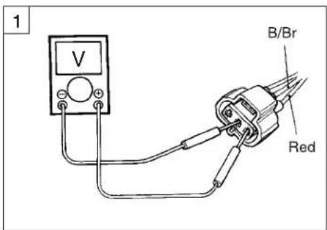

3
Remove the IAP sensor.
Connect the vacuum pump gauge to the vacuum port of the IAP sensor.
Arrange 3 new 1.5 V batteries in series (check that total voltage is 4.5 – 5.0 V) and connect ⊖ terminal to the ground terminal and ⊕ terminal to the Vcc terminal.
Check the voltage between Vout and ground. Also, check if voltage reduces when vacuum is applied up to 40 cmHg by using vacuum pump gauge. (See table below.)

109917-47010: Vacuum pump gauge
09900-25008: Multi circuit tester

Tester knob indication: Voltage (—)

flowchart
graph TD
    A["Yes"] --> B{If check result is not satisfactory, replace IAP sensor with a new one.}
    C["No"] --> B
Red, G/B or B/Br wire open or shorted to ground, or poor ⑩, ⑯ or ⑳ connection. (4-22)
If wire and connection are OK, intermittent trouble or faulty ECM.
Recheck each terminal and wire harness for open circuit and poor connection. (4-5)

3


ECM coupler
OUTPUT VOLTAGE (VCC VOLTAGE 4.5 – 5.0 V, AMBIENT TEMP. 20 – 30 °C, 68 – 86 °F)
| ALTITUDE(Reference) | ATMOSPHERIC PRESSURE | OUTPUT VOLTAGE | ||
| (ft) (m) | (mmHg) kPa | (V) | ||
| 0 | 0 | 760 | 100 | 3.4 – 4.0 |
| | | | | | | | | |
| 2 000 | 610 | 707 | 94 | |
| 2 001 | 611 | 707 | 94 | 3.0 – 3.7 |
| | | | | | | | | |
| 5 000 | 1 524 | 634 | 85 | |
| 5 001 | 1 525 | 634 | 85 | 2.6 – 3.4 |
| | | | | | | | | |
| 8 000 | 2 438 | 567 | 76 | |
| 8 001 | 2 439 | 567 | 76 | 2.4 – 3.1 |
| | | | | | | | | |
| 10 000 | 3 048 | 526 | 70 | |
"C14" TP SENSOR CIRCUIT MALFUNCTION
| DETECTED CONDITION POSSIBLE CAUSE | |
| Signal voltage low or high.Difference between actual throttle opening and opening calculated by ECM in larger than specified value. ( 0.10 V Sensor voltage & < 4.80 V \\ without the above range. ) | TP sensor maladjusted.TP sensor circuit open or short.TP sensor malfunction.ECM malfunction. |
INSPECTION
- Remove the fuel tank and air cleaner box. (4-52 and -60)
1 Turn the ignition switch OFF. Check the TP sensor coupler for loose or poor contacts. If OK, then measure the TP sensor input voltage. Disconnect the TP sensor/injector coupler ①. Turn the ignition switch ON. Measure the voltage at the Red wire and ground. If OK, then measure the voltage at the Red wire and B/Br wire.
DATA TIP sensor input voltage: 4.5 – 5.5 V (⊕Red)–⊖Ground (⊕Red)–⊖B/Br
09900-25008: Multi circuit tester Tester knob indication: Voltage (
Loose or poor contacts on the ECM coupler. Open or short circuit in the Red wire or B/Br wire. Yes
2 Turn the ignition switch OFF. Disconnect the TP sensor/injector coupler. Check the continuity between P/W wire and ground.
DATA TP sensor continuity: ∞ Ω (Infinity) (P/W - Ground) If OK, then measure the TP sensor resistance at the coupler (between P/W and B/Br wires). Turn the throttle grip and measure the resistance.
DATA TP sensor resistance Throttle valve is closed: Approx. 1.1 kΩ Throttle valve is opened: Approx. 4.3 kΩ
09900-25008: Multi circuit tester Tester knob indication: Resistance (Ω)

flowchart
graph TD
    A["No"] --> B["Reset the TP sensor position correctly. Replace the TP sensor with a new one."]
    C["Yes"] --> D["End"]

natural_image
Close-up of mechanical components with a white arrow pointing to a specific part (no visible text or symbols)


3
Connect the TP sensor/injector coupler ①. Insert the copper wires to the lead wire coupler. Turn the ignition switch ON. Measure the TP sensor output voltage at the coupler (between P/W and B/Br wires) by turning the throttle grip.
DATA
TP sensor output voltage
Throttle valve is closed : Approx. 1.1 V
Throttle valve is opened: Approx. 4.3 V
TOOL
09900-25008: Multi circuit tester
V
Tester knob indication: Voltage (—)
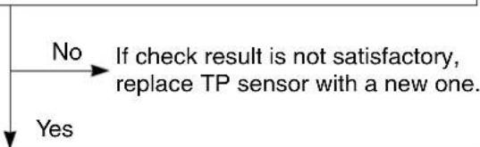
flowchart
graph TD
    A["No"] --> B{If check result is not satisfactory, replace TP sensor with a new one.}
    C["Yes"] --> B
Red, P/W or B/Br wire open or shorted to ground, or poor ⑩, ⑲ or ⑳ connection. (4-22) If wire and connection are OK, intermittent trouble or faulty ECM. Recheck each terminal and wire harness for open circuit and poor connection. (4-5)
Replace the ECM with a new one, and inspect it again.


"C15" ECT SENSOR CIRCUIT MALFUNCTION
| DETECTED CONDITION POSSIBLE CAUSE | |
| High engine coolant temp. (Low voltage – Low resistance)Low engine coolant temp. (High voltage – High resistance) | B/Bl circuit shorted to ground.B/Br circuit open.ECT sensor malfunction.ECM malfunction. |
INSPECTION
- Remove the vacuum damper. (4-61)
1 Turn the ignition switch OFF. Check the ECT sensor coupler for loose or poor contacts. If OK, then measure the ECT sensor voltage at the wire side coupler. Disconnect the coupler and turn the ignition switch ON. Measure the voltage between B/BI wire terminal and ground. If OK, then measure the voltage between B/BI wire terminal and B/Br wire terminal.
DATA ECT sensor voltage: 4.5 – 5.5 V (⊕B/BI)−⊖Ground (⊕B/BI)−⊖B/Br
09900-25008: Multi circuit tester Tester knob indication: Voltage (--)
No Loose or poor contacts on the ECM coupler. Open or short circuit in the B/BI wire or B/Br wire. Yes
2 Turn the ignition switch OFF. Measure the ECT sensor resistance. DATA ECT sensor resistance: 2.3 – 2.6 kΩ at 20°C (68°F) (Terminal - Terminal) TOOL 09900-25008: Multi circuit tester Tester knob indication: Resistance (Ω) Refer to page 5-8 for details. No Replace the ECT sensor with a new one. Yes
B/Bl or B/Br wire open or shorted to ground, or poor ③4 or ③6 connection. (4-22)
If wire and connection are OK, intermittent trouble or faulty ECM.
Recheck each terminal and wire harness for open circuit and poor connection. (4-5)
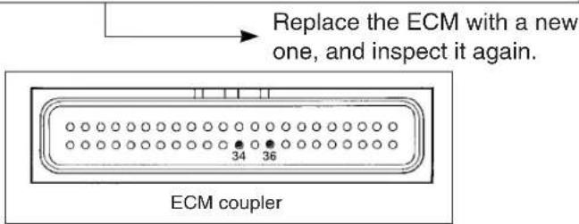

natural_image
Close-up of a mechanical assembly with a highlighted component (no visible text or symbols)

natural_image
Diagram of a multimeter connected to a connector with wires, no text or symbols present| Engine Coolant Temp. | Resistance |
| 20°C (68°F) | Approx. 2.45 kΩ |
| 40°C (104°F) | Approx. 1.148 kΩ |
| 60°C (140°F) | Approx. 0.587 kΩ |
| 80°C (176°F) | Approx. 0.322 kΩ |
"C21" IAT SENSOR CIRCUIT MALFUNCTION
| DETECTED CONDITION POSSIBLE CAUSE | |
| High intake air temp. (Low voltage – Low resistance)Low intake air temp. (High voltage – High resistance) | Dg circuit shorted to ground.B/Br circuit open.IAT sensor malfunction.ECM malfunction. |
INSPECTION
- Lift and support the fuel tank with its prop stay. (4-51)
1 Turn the ignition switch OFF. Check the IAT sensor coupler for loose or poor contacts. If OK, then measure the IAT sensor voltage at the wire side coupler. Disconnect the coupler and turn the ignition switch ON. Measure the voltage between Dg wire terminal and ground. If OK, then measure the voltage between Dg wire terminal and B/Br wire terminal. DATA IAT sensor voltage: 4.5 – 5.5 V

09900-25008: Multi circuit tester Tester knob indication: Voltage (--)

2 Turn the ignition switch OFF. Measure the IAT sensor resistance.
DATA IAT sensor resistance: 2.3 – 2.6 kΩ at 20°C (68°F) (Terminal – Terminal) TOOL 09900-25008: Multi circuit tester
Tester knob indication: Resistance (Ω) No Yes Replace the with a new c
Dg or B/Br wire open or shorted to ground, or poor ⑭ or ③ connection. (4-22) If wire and connection are OK, intermittent trouble or faulty ECM. Recheck each terminal and wire harness for open circuit and poor connection. (4-5) Replace the ECM with a new one, and inspect it again.


natural_image
Close-up of a mechanical component with a white plastic connector and wiring, no visible text or symbols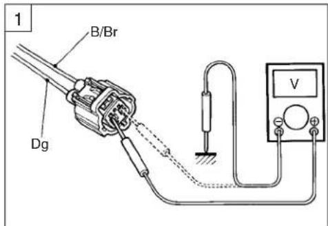

natural_image
Diagram of a multimeter connected to a terminal connector (no text or symbols present)| Intake Air Temp. | Resistance |
| 20°C (68°F) | Approx. 2.45 kΩ |
| 40°C (104°F) | Approx. 1.148 kΩ |
| 60°C (140°F) | Approx. 0.587 kΩ |
| 80°C (176°F) | Approx. 0.322 kΩ |
NOTE:
IAT sensor resistance measurement method is the same way as that of the ECT sensor. Refer to page 5-10 for details.
"C22" AP SENSOR CIRCUIT MALFUNCTION
| DETECTED CONDITION POSSIBLE CAUSE | |
| Low pressure and low voltage.High pressure and high voltage. ( 0.10 V Sensor voltage & < 4.80 V \\ without the above range. ) NOTE:Note that atmospheric pressure caries depending on weather conditions as well as altitude.Take that into consideration when inspecting voltage. | Clogged air passage with dust.Red wire circuit open or shorted to ground.B/Br or G/Y wire circuit shorted to ground.AP sensor malfunction.ECM malfunction. |
INSPECTION
- Remove the seat. (6-4)
1 Turn the ignition switch OFF. Check the AP sensor coupler for loose or poor contacts. If OK, then measure the AP sensor input voltage. Disconnect the AP sensor coupler. Turn the ignition switch ON. Measure the voltage between Red wire and ground. If OK, then measure the voltage between Red wire and B/Br wire terminal.
DATA AP sensor input voltage: 4.5 – 5.5 V (⊕Red)–⊖Ground (⊕Red)–⊖B/Br
09900-25008: Multi circuit tester Tester knob indication: Voltage (--)
No Loose or poor contacts on the ECM coupler. Open or short circuit in the Red wire or B/Br wire. Yes
2 Connect the AP sensor coupler. Insert the copper wires to the lead wire coupler. Turn the ignition switch ON. Measure the AP sensor output voltage at the wire side coupler between G/Y and B/Br wires.
DATA AP sensor output voltage: Approx. 4.0 V at 760 mmHg (100 kPa) (+G/Y - -B/Br)
09900-25008: Multi circuit tester Tester knob indication: Voltage (--)
No Check the air passage for clogging. Open or short circuit in the G/Y wire. Replace the AP sensor with a new one. Yes

natural_image
Close-up of mechanical components with a white arrow pointing to a specific part (no visible text or symbols)
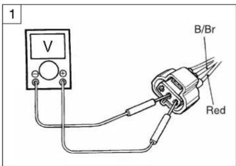

3
Remove the AP sensor.
Connect the vacuum pump gauge to the air passage port of the AP sensor.
Arrange 3 new 1.5 V batteries in series (check that total voltage is 4.5 – 5.0 V) and connect ⊖ terminal to the ground terminal and ⊕ terminal to the Vcc terminal.
Check the voltage between vout and ground. Also, check if voltage reduces when vacuum is applied up to 40 cmHg by using vacuum pump gauge. (See table below.)

109917-47010: Vacuum pump gauge
09900-25008: Multi circuit tester

Tester knob indication: Voltage (—)

flowchart
graph TD
    A["No"] --> B["If check result is not satisfactory, replace AP sensor with a new one."]
    C["Yes"] --> B
Red, G/Y or B/Br wire open or shorted to ground, or poor ⑩, ⑰ or ⑲ connection. (4-22)
If wire and connection are OK, intermittent trouble or faulty ECM.
Recheck each terminal and wire harness for open circuit and poor connection. (4-5)

3
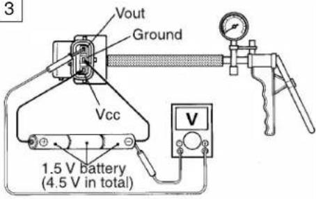
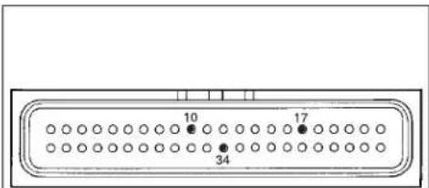
ECM coupler
OUTPUT VOLTAGE (VCC VOLTAGE 4.5 – 5.0 V, AMBIENT TEMP. 20 – 30 °C, 68 – 86 °F)
| ALTITUDE(Reference) | ATMOSPHERIC PRESSURE | OUTPUT VOLTAGE | ||
| (ft) (m) | (mmHg) kPa | (V) | ||
| 0 | 0 | 760 | 100 | 3.4 – 4.0 |
| | | | | | | | | |
| 2 000 | 610 | 707 | 94 | |
| 2 001 | 611 | 707 | 94 | 3.0 – 3.7 |
| | | | | | | | | |
| 5 000 | 1 524 | 634 | 85 | |
| 5 001 | 1 525 | 634 | 85 | 2.6 – 3.4 |
| | | | | | | | | |
| 8 000 | 2 438 | 567 | 76 | |
| 8 001 | 2 439 | 567 | 76 | 2.4 – 3.1 |
| | | | | | | | | |
| 10 000 | 3 048 | 526 | 70 | |
"C23" TO SENSOR CIRCUIT MALFUNCTION
| DETECTED CONDITION POSSIBLE CAUSE | |
| No TO sensor signal for more than 4 seconds, after ignition switch turns ON.Sensor voltage high.(0.2 V Sensor voltage < 4.6 V without the above range. | TO sensor circuit open or short.TO sensor malfunction.ECM malfunction. |
INSPECTION
- Remove the seat. (6-4)
1 Turn the ignition switch OFF.
Check the TO sensor coupler for loose or poor contacts.
If OK, then measure the TO sensor resistance.
Disconnect the TO sensor coupler.
Measure the resistance between Red and B/Br wire terminals.
DATA TO sensor resistance: 19.1 - 19.7 kΩ (Red - B/Br)
09900-25008: Multi circuit tester
Tester knob indication: Resistance (Ω)

flowchart
graph TD
    A["Yes"] --> B{No}
    B --> C["Replace the TO sensor with a new one."]
2 Connect the TO sensor coupler.
Insert the copper wires to the lead wire coupler.
Turn the ignition switch ON.
Measure the voltage at the wire side coupler between Br/W and B/Br wires.
DATA TO sensor voltage: 0.4 – 1.4 V (Br/W – B/Br)
Also, measure the voltage when leaning of the motorcycle. Dismount the TO sensor from its bracket and measure the voltage when it is leaned more than 65irc , left and right, from the horizontal level.
DATA TO sensor voltage: 3.7 – 4.4 V (Br/W – B/Br)
09900-25008: Multi circuit tester
Tester knob indication: Voltage (--)
No
Loose or poor contacts on the ECM coupler.
Open or short circuit in the Br/W wire or B/Br wire.
Replace the TO sensor with a new one.
Red, Br/W or B/Br wire open or shorted to ground, or poor ⑩, ④ or ③ connection. (4-22) If wire and connection are OK, intermittent trouble or faulty ECM. Recheck each terminal and wire harness for open circuit and poor connection. (4-5)
Replace the ECM with a new one, and inspect it again.

natural_image
Close-up of mechanical components with a white arrow pointing to a component (no visible text or symbols)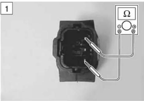
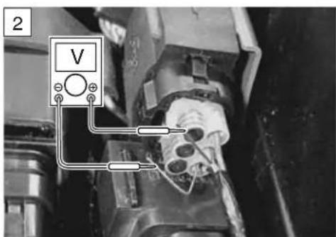

"C24" or "C25" IGNITION SYSTEM MALFUNCTION
*REFER TO THE IGNITION SYSTEM FOR DETAILS. (7-19)
"C28" STV ACTUATOR CIRCUIT MALFUNCTION
DETECTED CONDITION POSSIBLE CAUSE
| The operation voltage does not reach the STVA. ECM does not receive communication signal from the STVA. | • STVA malfunction.• STVA circuit open or short.• STVA motor malfunction. |
INSPECTION
- Remove the fuel tank and air cleaner element. (4-52 and 2-4)
1
Turn the ignition switch OFF.
Check the STVA lead wire coupler for loose or poor contacts.
Turn the ignition switch ON to check the STV operation. STV operating order: Half open → full close → Full open → 75% open → Half open (about 20 seconds later)
Yes
No
Loose or poor contacts on the STVA coupler.
Open or short circuit in the Red and Black wires.
2
Turn the ignition switch OFF.
Check the STVA lead wire coupler for loose or poor contacts.
Disconnect the STVA lead wire coupler.
Check the continuity between Red wire and ground.
DATA
STVA continuity: ∞Ω (Infinity)
If OK, then measure the STVA resistance. (between Red and Black wires)
DATA
STVA resistance: Approx. 4.8 - 7.2 Ω
(⊕ Red - ⊖ Black)

09900-25008: Multi circuit tester

Tester knob indication: Resistance (Ω)
flowchart
graph TD
    A["Yes"] --> B["No"]
    B --> C["Replace the STVA with a new one."]
Loose or poor contacts on the STVA coupler, or poor ⑳ or ㉒ connection. (4-22)
If wire and connection are OK, intermittent trouble or faulty ECM. Recheck each terminal and wire harness for open circuit and poor connection. (4-5)
Replace the ECM with a new one, and inspect it again.
1
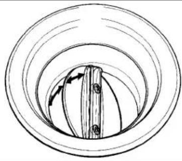
natural_image
Diagram of a spiral structure with internal curved lines and directional arrows, no text or symbols present2

2


natural_image
Front view of a 22-pin electronic connector with pinout and mounting holes (no text or symbols)ECM coupler
"C29" STP SENSOR CIRCUIT MALFUNCTION
| DETECTED CONDITION POSSIBLE CAUSE | |
| Signal voltage low or high.Difference between actual throttle opening and opening calculated by ECM in larger than specified value.(0.10 V Sensor voltage < 4.80 V without the above range. | • STP sensor maladjusted.• STP sensor circuit open or short.• STP sensor malfunction.• ECM malfunction. |
INSPECTION
- Remove the fuel tank and air cleaner box. (4-52 and -60)


2 Turn the ignition switch OFF. Disconnect the STP sensor coupler. Check the continuity between T3 terminal wire and ground.
DATA STP sensor continuity: ∞ Ω (Infinity)
(T 3 terminal - Ground)
If OK, then measure the STP sensor resistance at the coupler (between T3 and T4 terminals).
Close and open the secondary throttle valve by finger, and measure the valve closing and opening resistance.
DATA STP sensor resistance Secondary throttle valve is closed: Approx. 1.1 kΩ Secondary throttle valve is opened: Approx. 4.3 kΩ
09900-25008: Multi circuit tester Tester knob indication: Resistance (Ω)


natural_image
Close-up of mechanical components with a white arrow pointing to a specific part (no visible text or symbols)
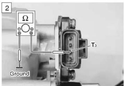


3 Turn the ignition switch OFF. Connect the STP sensor coupler. Insert the copper wires to the lead wire coupler. Disconnect the STVA lead wire coupler. Turn the ignition switch ON. Measure the STP sensor output voltage at the coupler (between Yellow and B/Br wires) by turning the secondary throttle valve (close and open) with a finger.
DATA STP sensor output voltage Throttle valve is closed: Approx. 1.1 V Tester knob indication : Approx. 4.3 V
09900-25008: Multi circuit tester Tester knob indication: Voltage (--)
No If check result is not satisfactory, replace STP sensor with a new one. Yes
Red, Yellow or B/Br wire open or shorted to ground, or poor ⑩, ④ or ③ connection. (4-22) If wire and connection are OK, intermittent trouble or faulty ECM. Recheck each terminal and wire harness for open circuit and poor connection. (4-5)
"C31" GEAR POSITION (GP) SWITCH CIRCUIT MALFUNCTION
| DETECTED CONDITION POSSIBLE CAUSE | |
| No Gear Position switch voltageSwitch voltage low.(Switch Voltage > 1.0 V without the above value. | Gear Position switch circuit open or short.Gear Position switch malfunction.ECM malfunction. |
INSPECTION
- Lift and support the fuel tank with its prop stay. (4-51)
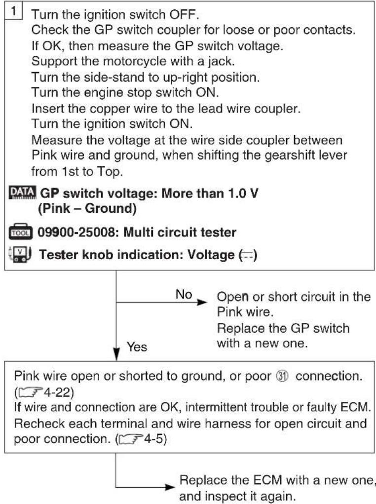

natural_image
Close-up of automotive electrical wiring and connectors (no visible text or symbols)

"C32" or "C33" FUEL INJECTION MALFUNCTION
| DETECTED CONDITION POSSIBLE CAUSE | |
| No injector current. • Injector circuit open or short. | • Injector malfunction.• ECM malfunction. |
INSPECTION
- Remove the fuel tank and air cleaner box. (4-52 and -60)
1 Turn the ignition switch OFF. Check the injector coupler for loose or poor contacts. If OK, then measure the injector resistance. Disconnect the TP sensor/injector coupler and measure the resistance between lead wires.
DATA Injector resistance: 12 – 18 Ω at 20°C (68°F) ( No.1 : Y/R – Gr/W No. 2 : Y/R – Gr/B
If OK, then check the continuity between Y/R wire and ground.
DATA Injector continuity: ∞ Ω (Infinity) (Y/R - Ground)
09900-25008: Multi circuit tester
Tester knob indication: Resistance (Ω)
No Replace the injector with a new one. (4-67) Yes
2 Turn the ignition switch ON. Measure the injector voltage between Y/R wire and ground.
DATA Injector voltage: Battery voltage (Y/R - Ground)
NOTE: Injector voltage can be detected only 3 seconds after ignition switch is turned ON.
09900-25008: Multi circuit tester
Tester knob indication: Voltage (--)
No Open circuit in the Yellow/Red wire. Yes
Gr/W, Gr/B or Y/R wire open or shorted to ground, or poor ⑤, ⑥ or ⑳ connection. (4-22)
If wire and connection are OK, intermittent trouble or faulty ECM.
Recheck each terminal and wire harness for open circuit and poor connection. (4-5)
Replace the ECM with a new one, and inspect it again.

natural_image
Close-up of mechanical components with arrows pointing to features (no visible text or symbols)
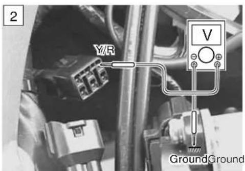

natural_image
Diagram of a 28-pin connector pinout with no text or symbolsECM coupler
"C41" FP RELAY CIRCUIT MALFUNCTION
DETECTED CONDITION POSSIBLE CAUSE
| No signal from fuel pump relay. • Fuel pump relay circuit open or short. • Fuel pump relay malfunction. • ECM malfunction. |
INSPECTION
- Remove the seat. (6-4)

flowchart
graph TD
    A["1 Turn the ignition switch OFF.<br>Check the FP relay coupler for loose or poor contacts.<br>If OK, then check the insulation and continuity. Refer to page 4-51 for details."] --> B{No}
    B -->|Yes| C["Y/B or O/W wire open or shorted to ground, or poor ③2 or ②8 connection. (4-22)<br>If wire and connection are OK, intermittent trouble or faulty ECM.<br>Recheck each terminal and wire harness for open circuit and poor connection. (4-5)"]
    C --> D["Replace the ECM with a new one,<br>and inspect it again."]

natural_image
Close-up of a mechanical component with a highlighted part and arrow indicator (no readable text or symbols)
"C42" IG SWITCH CIRCUIT MALFUNCTION
* Refer to the IGNITION SWITCH INSPECTION for details.
- Remove the fuel tank and air cleaner box. (4-52 and -60)
- Inspect the ignition switch. (7-32)
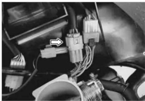
natural_image
Close-up of automotive electrical connectors and wiring (no visible text or symbols)| DETECTED CONDITION POSSIBLE CAUSE | |
| Output voltage of HO2 Sensor higher than the specification or lower than the specification. | H O 2 sensor or its circuit open or short.Fuel system malfunction.ECM malfunction. |
INSPECTION
- Remove the engine under cover and seat. (3-3 and 6-4)
1 Turn the ignition switch OFF. Check the HO₂ sensor coupler for loose or poor contacts. If OK, then check the continuity. Disconnect the HO₂ sensor coupler and ECM coupler. Check the continuity between the HO₂ sensor coupler terminal (White/Green) and ECM coupler terminal (White/Green). Also, check the infinity between the HO₂ sensor coupler terminal and ground.
09900-25008: Multi circuit tester Tester knob indication: Continuity (●))
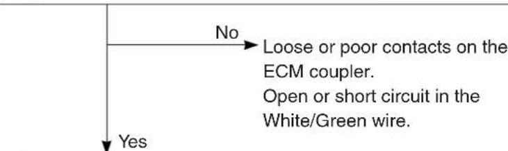
2 Connect the HO2 sensor coupler and ECM coupler. Insert the copper wires to the HO2 sensor lead wire coupler. Start the engine and warm up the engine up to engine coolant temperature is 80 °C (176 °F). Measure the HO2 sensor output voltage at the coupler (between White/Green and Black/Brown wires) when idling condition. Also, measure the HO2 sensor output voltage while holding the engine speed at 5 000 r/min.
DATA HO2 sensor output voltage at idle speed: less than 0.4 V (+ W/G - ⊖ B/Br) HO2 sensor output voltage at 5 000 r/min: more than 0.6 V (+ W/G - ⊖ B/Br)
09900-25008: Multi circuit tester Tester knob indication: Voltage (—)

natural_image
Close-up of mechanical components with wires and a white arrow pointing to a component (no visible text or symbols)
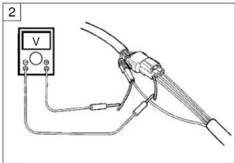
No
Replace the HO2 sensor with a new one.
Yes
3 Turn the ignition switch OFF.
Insert the copper wire to the ECM lead wire coupler ⑧ terminal (Heater circuit).
Turn the ignition switch ON and measure the heater voltage between ⑧ terminal and ground.
If the tester voltage indicates the battery voltage for few seconds it is good condition.
DATA Heater voltage: Battery voltage
(⑧ terminal – Ground)
NOTE:
Battery voltage can be detected only during few seconds after ignition switch is turned ON.

09900-25008: Multi circuit tester

Tester knob indication: Voltage (—)
Yes
No
Replace the HO2 sensor with a new one.
4 Turn the ignition switch OFF.
Disconnect the HO2 sensor coupler.
Check the resistance between the terminals (White – White) of the HO2 sensor.
DATA H 0 sensor resistance: 4 – 5 Ω (at 23 °C/73.4 °F)
NOTE:
* Temperature of the sensor affects resistance value largely.
* Make sure that the sensor heater is at correct temperature.

09900-25008: Multi circuit tester set

Tester knob indication: Resistance (Ω)
Yes
No
Replace the HO2 sensor with a new one.
Black, W/Gr, White, W/B, Gray, B/Br or O/W wire open or shorted to ground, or poor ⑧, ⑮, ⑳ or ⑴ connection.
(4-22)
If wire and connection are OK, intermittent trouble or faulty ECM.
Recheck each terminal and wire harness for open circuit and poor connection. (4-5)
Check the fuel supply system, if the system is OK, replace the ECM with a new one, and inspect it again.

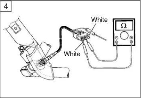
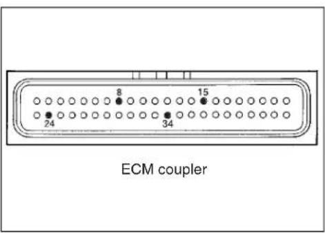
FUEL SYSTEM
FUEL TANK LIFT-UP
- Remove the seat. (6-4)
- Remove the fuel tank side covers, left and right.
- Remove the cowling fitting bolts, left and right.
- Remove the fuel tank top cover by removing the bolts and fasteners.
- Remove the fuel tank mounting bolt.
- Lift and support the fuel tank with the fuel tank prop stay.

FUEL TANK REMOVAL
- Lift and support the fuel tank with the fuel tank prop stay. (4-51)
- Disconnect the fuel pump lead wire coupler ①.
- Place a rag under the fuel feed hose and disconnect the feed hose ② from the fuel tank.
CAUTION
When removing the fuel tank, do not leave the fuel feed hose ② on the fuel tank side.
WARNING
Gasoline is highly flammable and explosive. Keep heat, spark and flame away.
- Remove the fuel tank mounting bolt.
- Remove the fuel tank.

FUEL TANK INSTALLATION
• Installation is in the reverse order of removal.

natural_image
Close-up of mechanical components with a circular detail on a surface (no visible text or symbols)FUEL PRESSURE INSPECTION
- Lift and support the fuel tank with the fuel tank prop stay. (4-51)
- Place a rag under the fuel feed hose. (4-52)
- Remove the fuel feed hose and install the special tools between the fuel tank and fuel delivery pipe.

09940-40211: Fuel pressure gauge adaptor
09940-40220: Fuel pressure gauge hose attachment
09915-77330: Oil pressure gauge
09915-74520: Oil pressure gauge hose
Turn the ignition switch ON and check the fuel pressure.
DATA
Fuel pressure: Approx. 300 kPa (3.0 kgf/cm², 43 psi)
If the fuel pressure is lower than the specification, inspect the following items:
* Fuel hose leakage
* Clogged fuel filter
* Pressure regulator
* Fuel pump
If the fuel pressure is higher than the specification, inspect the following items:
* Fuel pump check valve
* Pressure regulator
WARNING
* Before removing the special tools, turn the ignition switch to OFF position and release the fuel pressure slowly.
* Gasoline is highly flammable and explosive. Keep heat, sparks and flame away.
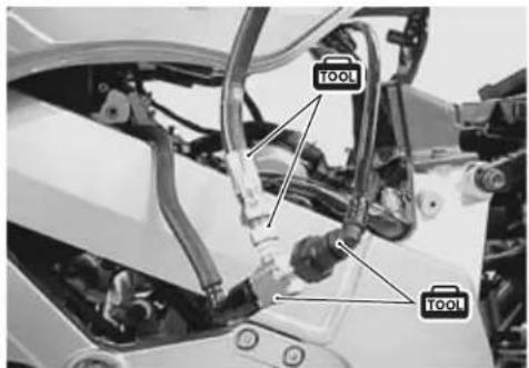
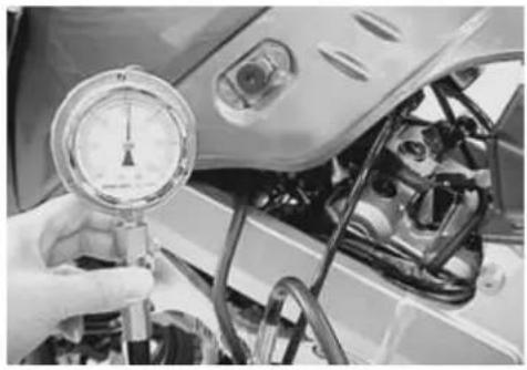
natural_image
Close-up of a car hood with a pressure gauge and mechanical components (no visible text or symbols)
FUEL PUMP INSPECTION
Turn the ignition switch ON and check that the fuel pump operates for few seconds.
If the fuel pump motor does not make operating sound, replace the fuel pump assembly or inspect the fuel pump relay and tip over sensor.
FUEL DISCHARGE AMOUNT INSPECTION
WARNING
Gasoline is highly flammable and explosive. Keep heat, spark and flame away.
- Lift and support the fuel tank with the fuel tank prop stay. (4-51)
- Disconnect the fuel feed hose from the fuel tank.
- Connect a proper fuel hose to the fuel pump.
- Place the measuring cylinder and insert the fuel hose end into the measuring cylinder.
- Disconnect the ECM lead wire coupler.
- Push the lock Ⓐ to pull out the power source lead wire (Yellow with red tracer).
- Apply 12 volts to the fuel pump for 60 seconds and measure the amount of fuel discharged.
Battery ⊕ terminal — Power source lead wire ① (Yellow with red tracer)
If the pump does not discharge the amount specified, it means that the fuel pump is defective or that the fuel filter is clogged.
DATA Fuel discharge amount: Approx. 1 200 ml/60 sec. (1.3/1.1 US/lmp oz)/60 sec.

natural_image
Close-up of a mechanical assembly with visible components and joints (no text or symbols)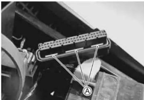
natural_image
Close-up of an automotive electrical connector with labeled terminals (no readable text or symbols)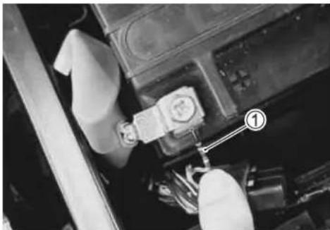
natural_image
Close-up of hands installing or adjusting a component with a tool, no visible text or symbolsNOTE:
The battery must be in fully charged condition.
FUEL PUMP RELAY INSPECTION
Fuel pump relay is located behind the ECM.
- Remove the seat.
- Remove the fuel pump relay.
First, check the insulation between ① and ② terminals with pocket tester. Then apply 12 volts to ③ and ④ terminals, + to ③ and - to ④, and check the continuity between ① and ②. If there is no continuity, replace it with a new one.

natural_image
Close-up of a mechanical component with a highlighted square and arrow pointing to a small feature (no visible text or symbols)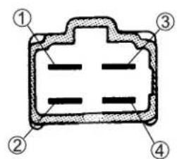
FUEL PUMP AND FUEL FILTER REMOVAL
- Remove the fuel tank. (4-52)
- Remove the fuel pump assembly by removing its mounting bolts diagonally.
WARNING
Gasoline is highly flammable and explosive. Keep heat, spark and flame away.
- Remove the fuel level gauge.

natural_image
Close-up of a mechanical component with circular features and wiring (no visible text or symbols)
natural_image
Close-up of a mechanical device with a cylindrical component and two circular features, no visible text or symbols.- Remove the nuts.

natural_image
Close-up of a mechanical device with three circular connectors on its base (no visible text or symbols)- Remove the screws.
- Remove the fuel pump assy from the fuel pump plate.
- Remove the fuel pump holder.
- Remove the fuel mesh filter.
- Remove the fuel pressure regulator holder ① and the fuel pressure regulator ②.

natural_image
Close-up of a metallic mechanical component with two circular annotations pointing to features (no visible text or symbols)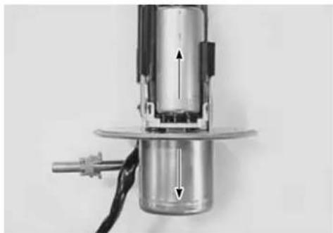
natural_image
Close-up of a mechanical device with internal components and directional arrows (no visible text or symbols)
natural_image
Close-up of a mechanical component with directional arrows indicating movement or force (no text or symbols visible)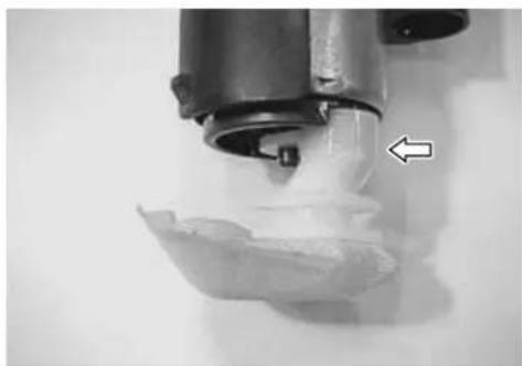
natural_image
Close-up of a 3D printer nozzle dispensing liquid into a small container, with an arrow pointing to the tip (no visible text or symbols)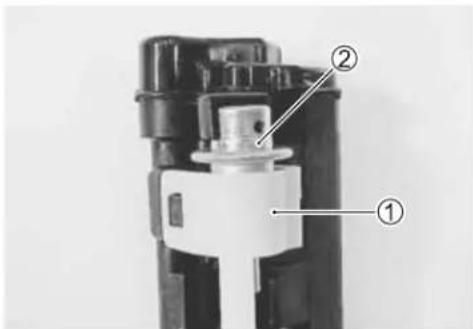
FUEL MESH FILTER INSPECTION AND CLEANING
If the fuel mesh filter is clogged with sediment or rust, fuel will not flow smoothly and loss in engine power may result.
Blow the fuel mesh filter with compressed air.
NOTE:
If the fuel mesh filter is clogged with many sediment or rust, replace the fuel filter cartridge with a new one.
FUEL PUMP AND FUEL MESH FILTER INSTALLATION
Install the fuel pump and fuel mesh filter in the reverse order of removal, and pay attention to the following points:
• Install the new O-rings to the fuel pressure regulator and fuel pipe.
- Apply thin coat of the engine oil to the O-rings.
CAUTION
Use the new O-rings to prevent fuel leakage.
- Tighten the screws together with the lead wire terminals.
- Tighten the nuts together with the lead wire terminals.
Ⓐ...... + terminal for fuel pump
⑧...... + terminal for fuel level gauge
©..... - terminal for fuel level gauge
• Install the fuel level gauge.
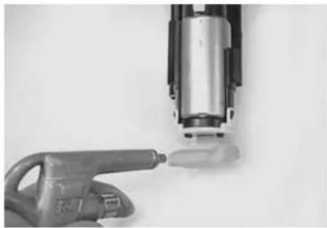
natural_image
Close-up of a mechanical device with a tool and a metallic component, no visible text or symbols
natural_image
Close-up of a hand holding a mechanical component with a small labeled tag (no visible text or symbols)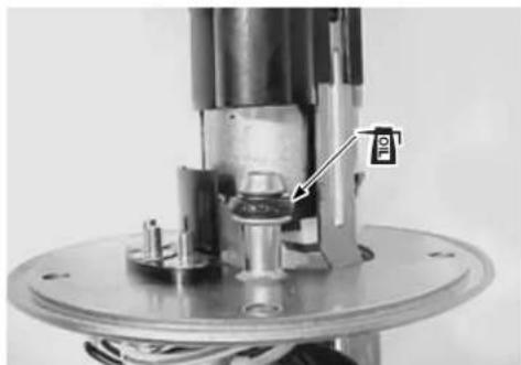
natural_image
Close-up of a mechanical assembly with a central component and a labeled sensor (no visible text or symbols)
natural_image
Close-up of a metallic mechanical component with two circular annotations pointing to features (no visible text or symbols)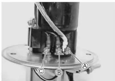
• Install the new O-ring and apply grease to it.
WARNING
The O-ring must be replaced with a new one to prevent fuel leakage.

99000-25030: SUZUKI SUPER GREASE "A" (USA) 99000-25010: SUZUKI SUPER GREASE "A" (Others)
- When installing the fuel pump assembly, first tighten all the fuel pump assembly mounting bolts lightly in the ascending order of numbers, and then tighten them to the specified torque in the above tightening order
Fuel pump mounting bolt: 10 N·m (1.0 kgf·m, 7.3 lb·ft)
NOTE:
Apply a small quantity of the THREAD LOCK "1342" to the thread portion of the fuel pump mounting bolt.

99000-32050: THREAD LOCK "1342"

natural_image
Close-up of a mechanical component with a central circular opening and mounting holes (no visible text or symbols)

① Fuel pressure regulator
② Fuel pump case/Fuel filter cartridge (For high pressure)
③ Fuel pump
④ Fuel mesh filter (For low pressure)
⑤ Fuel level gauge
THROTTLE BODY AND STV ACTUATOR CONSTRUCTION
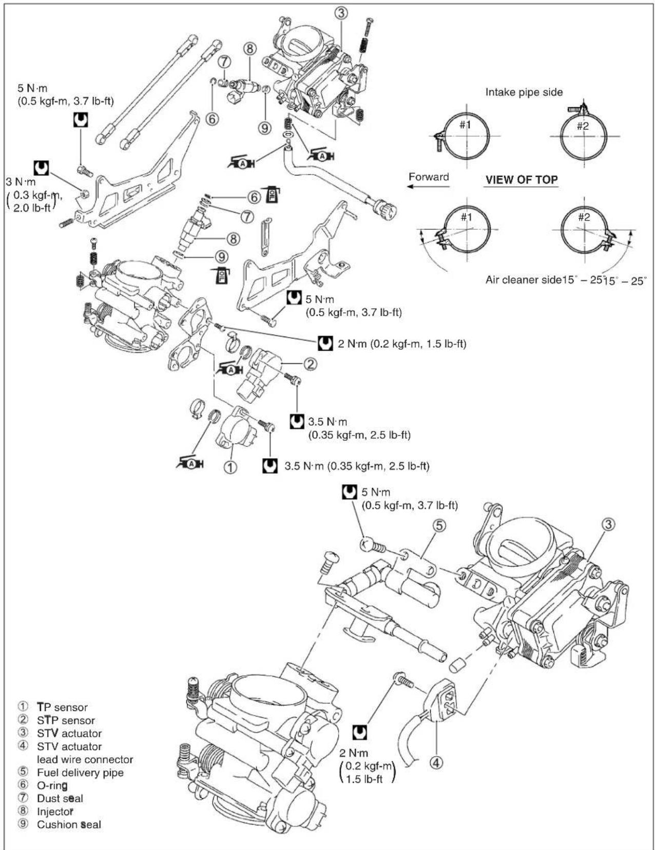
THROTTLE BODY REMOVAL
- Remove the fuel tank. (4-52)
- Loosen the respective throttle body clamp screws (air cleaner side).
- Disconnect the *PAIR solenoid valve lead wire coupler, IAP senor coupler and IAT sensor coupler.
- Disconnect the PAIR hoses from the PAIR solenoid valve.
- Remove the air cleaner box.
* For E-24 model is operated by the vacuum.
- Loosen the respective throttle body clamp screws (intake pipe side).

- Disconnect the various lead wire couplers.
① STP sensor
② TP sensor/Fuel injector
③ STVA motor
- Disconnect the throttle cables from their drum.
- Dismount the throttle body assembly.
CAUTION
* Be careful not to damage the throttle cable bracket and fast idle lever when dismounting or remounting the throttle body assembly.
* After disconnecting the throttle cables, do not snap the throttle valve from full open to full close. It may cause damage to the throttle valve and throttle body.
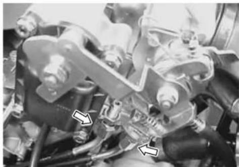
natural_image
Close-up of an automotive engine assembly with visible hoses and components (no text or symbols)THROTTLE BODY DISASSEMBLY
- Remove the IAP sensor vacuum damper and its hose.
- Remove the throttle link rod ① and secondary throttle link rod ②.
NOTE:
The throttle link rod① is longer than the secondary throttle link rod ②.
- Remove the fuel delivery pipe.

natural_image
Mechanical assembly diagram showing motor components and wiring (no text or labels visible)

natural_image
Close-up of mechanical components with four circular features, no visible text or symbols- Remove the fuel injectors.
- Disconnect the TPS coupler.
- Remove the TPS and STPS with the special tool.

09930-11950: Torx wrench
NOTE:
Prior to disassembly, mark each sensor's original position with a paint or scribe for accurate reinstallation.
- Remove the fast idle cam ① by removing its mounting nut.
CAUTION
Do not attempt to disassemble the secondary throttle valve actuator assembly. (Except for the cover ②) Actuator is available only as an assembly.
- Remove the STVA motor lead wire connector ③ by removing the screw.

natural_image
Close-up of mechanical components and connectors, no visible text or symbols
natural_image
Close-up of a mechanical assembly with no visible text or symbols
natural_image
Close-up of mechanical components with four circular annotations highlighting specific parts (no readable text or symbols)

natural_image
Close-up of a mechanical component with a circular inset highlighting a central feature, labeled with number ③ (no readable text or symbols)CAUTION
Never remove the STVA motor yoke and motor.
CAUTION
Avoid removing the STV adjuster Ⓐ unless absolutely necessary.
CAUTION
Never remove the throttle valve and secondary throttle valve.

natural_image
Close-up of mechanical components with no visible text or symbols
natural_image
Close-up of a mechanical component with labeled parts (A and a circle), no readable text or symbols present.
natural_image
Close-up of a mechanical component with two circular features, no visible text or symbols
natural_image
Close-up of a mechanical valve or pump component with two circular features on the side (no visible text or symbols)- Remove the throttle body link plates.
- Remove the throttle lever No.2 ① and secondary throttle lever No.2 ②.
- Remove the throttle lever No.1 ③ and secondary throttle lever No.1 ④.

natural_image
Mechanical assembly with multiple metal components and circular annotations (no readable text or symbols)
natural_image
Mechanical assembly diagram showing a mechanical component with labeled parts (① and an arrow), no readable text or symbols present.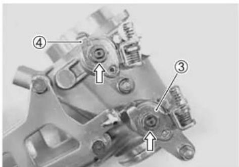

natural_image
Mechanical component with labeled parts (② and an arrow), no readable text or symbols present.THROTTLE BODY CLEANING
WARNING
Some carburetor cleaning chemicals, especially dip-type soaking solutions, are very corrosive and must be handled carefully. Always follow the chemical manufacturer's instructions on proper use, handling and storage.
- Clean all passageways with a spray-type carburetor cleaner and blow dry with compressed air.
CAUTION
Do not use wire to clean passageways. Wire can damage passageways. If the components cannot be cleaned with a spray cleaner it may be necessary to use a dip-type cleaning solution and allow them to soak. Always follow the chemical manufacturer's instructions for proper use and cleaning of the throttle body components. Do not apply carburetor cleaning chemicals to the rubber and plastic materials.
INSPECTION
Check following items for any damage or clogging.
* O-ring * Fuel injector filter
*Throttle shaft bushing and seal *Injector cushion seal
*Throttle valve *Injector dust seal
*Secondary throttle valve *Vacuum hose
THROTTLE BODY REASSEMBLY
Reassemble the throttle body in the reverse order of disassembly.
Pay attention to the following points:
- Be careful not to apply grease to the other parts when applying the grease to the shaft.

99000-25030: SUZUKI SUPER GREASE "A" (USA)
99000-25010: SUZUKI SUPER GREASE "A" (Others)
• Install the actuator cover ①.
NOTE:
Before installing the cover ①, apply grease lightly to the dust seal Ⓐ.

99000-25030: SUZUKI SUPER GREASE "A" (USA)
99000-25010: SUZUKI SUPER GREASE "A" (Others)
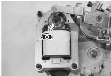
natural_image
Close-up of a mechanical assembly with no visible text or symbols
- Apply thread lock "1342" to the actuator cover nuts and tighten them.

99000-32050: THREAD LOCK "1342"

STVA cover nut: 2.0 N·m (0.2 kgf·m, 1.5 lb·ft)
• Install the fast idle cam and tighten its mounting nut.

Fast idle cam mounting nut: 4.0 N·m (0.4 kgf-m, 3.0 lb-ft)
- Tighten the throttle body link plate bolts securely.

Throttle body link plate bolt: 5 N·m (0.5 kgf-m, 3.7 lb-ft)
- Position the TV control lever between the TV synchronizing screw Ⓐ and spring as shown.
- Set each TV to the same opening by turning the synchronizing screw Ⓐ.
- Position the STV control lever between the STV balance screw Ⓑ and spring as shown.
NOTE:
Apply grease to the screw end and spring if necessary.
- Apply thin coat of the engine oil to the new fuel injector cushion seals ①, and install them to each fuel injector.
CAUTION
Replace the cushion seal with a new one.
• Install the seal ② and O-ring ③ to each fuel injector.
- Apply thin coat of the engine oil to the new O-rings③.
• Install the fuel injectors by pushing them straight to each throttle body.
CAUTION
Replace the dust seal and O-ring with the new ones. Never turn the injector while pushing it.
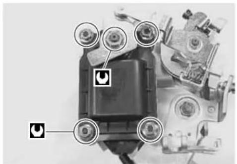
natural_image
Close-up of mechanical components with circular annotations pointing to features (no readable text or symbols)
natural_image
Mechanical assembly with labeled components and a small symbol (no readable text or symbols)
natural_image
Close-up of mechanical components with labeled parts A and B, showing no readable text or symbols.

natural_image
Close-up of a mechanical bracket with mounting holes and structural components (no visible text or symbols)- Connect the fuel injector couplers to the fuel injectors.
NOTE:
The fuel injector coupler No.1 (FRONT) can be distinguished from that of the No.2 (REAR) by the "F" mark.
• Install the fuel delivery pipe assembly to the throttle body assembly.
CAUTION
Never turn the fuel injectors while installing them.
- Tighten the fuel delivery pipe mounting screws.

Fuel delivery pipe mounting screw:
5 N·m (0.5 kgf-m, 3.7 lb-ft)
• Install the throttle link rod ① and secondary throttle link rod ②.
NOTE:
The throttle link rod① is longer than the secondary throttle link rod ②.
- Apply a small quantity of grease to the shaft ends and seal lips.

99000-25030: SUZUKI SUPER GREASE "A" (USA)
99000-25010: SUZUKI SUPER GREASE "A" (Others)
- With the STV fully closed, install the STP sensor.

09930-11950: Torx wrench

STP sensor mounting screw: 3.5 N·m(0.35 kgf·m, 2.5 lb·ft)
NOTE:
STP sensor and TP sensor reassemble each other very closely in external appearance.
Make sure to check the terminal numbers of coupler.
STP sensor: 4-pin TPS sensor: 3-pin

natural_image
Close-up of mechanical components with a highlighted circular detail (no visible text or symbols)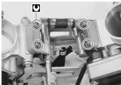
natural_image
Mechanical assembly with four circular components and a small labeled component (no readable text or symbols)

natural_image
Close-up of mechanical components with no visible text or symbols
natural_image
Close-up of hands holding a mechanical component with no visible text or symbols- With the TV fully closed, install the TP sensor.

09930-11950: Torx wrench

TP sensor mounting screw: 3.5 N·m (0.35 kgf·m, 2.5 lb·ft)
- Set each STV to the same opening by turning the balance screw ①.

natural_image
Close-up of a hand holding a mechanical component with no visible text or symbols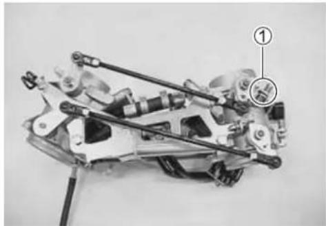
natural_image
Mechanical assembly diagram showing a motor with labeled parts (1 and 2), no readable text or symbols present.STP SENSOR ADJUSTMENT
If the STP sensor adjustment is necessary, measure the sensor resistance and adjust the STP sensor positioning as follows:
- Disconnect the STP sensor coupler.
- Set the ST valve to fully close position by finger and measure the resistance T3 and T4 terminals.

STP sensor setting resistance
ST valve is fully closed: Approx. 1.1 kΩ
( T _ 3 - T _ 4)


09900-25008: Multi circuit tester

Tester knob indication: Resistance (Ω)
- Loosen the STP sensor mounting screws.
- Adjust the STP sensor until resistance is within specification and tighten the STP sensor mounting screws.

09930-11950: Torx wrench

STP sensor mounting screw:
3.5 N·m (0.35 kgf-m, 2.5 lb-ft)

natural_image
Close-up of a hand holding a mechanical component, alongside a close-up of a mechanical component with circular features and a directional arrow (no visible text or symbols)If the measured resistance is not within specification, adjust the STV adjuster Ⓐ as follows:
- Under above condition, turn in or out the STV adjuster Ⓐ until the resistance becomes specified value.
If the measured resistance is not obtain, replace the STP sensor with a new one, and adjust the STP sensor positioning again.
NOTE:
To adjust the TP sensor, install the throttle body assembly to the engine and after warming up engine. (4-64)
THROTTLE BODY INSTALLATION
Installation is in the reverse order of removal. Pay attention to the following points:
- Connect the throttle pulling cable and throttle returning cable to the throttle cable drum.
- Adjust the throttle cable play with the cable adjusters. Refer to page 2-15 for details.
TP SENSOR ADJUSTMENT
• After checking or adjusting the throttle valve synchronization, adjust the TP sensor positioning as follows:
- After warming up engine, adjust the idling speed to 1 200 ± 100 rpm.
- Stop the warmed-up engine and connect the special tool to the dealer mode coupler. (4-24)

09930-82710: Mode select switch
- If the TP sensor adjustment is necessary, loosen the TP sensor mounting screws.
- Turn the TP sensor and bring the line to middle.
- Tighten the TP sensor mounting screws.

09930-11950: Torx wrench

TP sensor mounting screw: 3.5 N·m (0.35 kgf·m, 2.5 lb·ft)

natural_image
Close-up of a mechanical component with a circular annotation labeled 'A' pointing to a textured surface (no readable text or symbols beyond label)
natural_image
Close-up of mechanical components with no visible text or symbols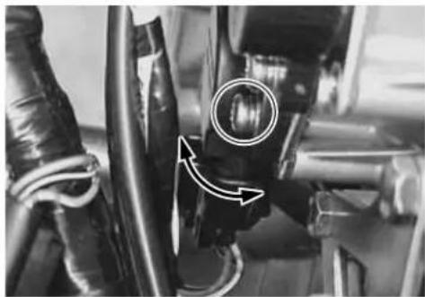
natural_image
Close-up of mechanical components with a circular arrow indicating a specific feature (no text or symbols visible)
← Incorrect
← Correct position
← Incorrect
FUEL INJECTOR INSPECTION
The fuel injector can be checked without removing it from the throttle body.
Refer to page 4-47 for details.

natural_image
Close-up of a black mechanical component with a protruding arm and connector (no visible text or symbols)FUEL INJECTOR REMOVAL
- Remove the fuel tank and air cleaner box. (4-52 and -60)
- Remove the fuel delivery pipe assembly. (4-61)
- Disconnect the injector couplers.
- Remove the fuel injectors No.1 and No.2. (4-62)
INSPECTION
Check fuel injector filter for evidence of dirt and contamination. If present, clean and check for presence of dirt in the fuel lines and fuel tank.
FUEL INJECTOR INSTALLATION
- Apply thin coat of the engine oil to new injector cushion seals and O-rings.
- Install the injector by pushing it straight to the throttle body. Never turn the injector while pushing it. (4-67)
FAST IDLE INSPECTION
The fast idle system is automatic type.
When the fast idle cam is turned by the secondary throttle valve actuator, the cam pushes the lever on the throttle valve shaft causing the throttle valve to open and raise the engine speed. When the engine has warmed up, depending on the water temperature and ambient temperature as shown in the following table, the fast idle is cancelled allowing the engine to resume idle speed.
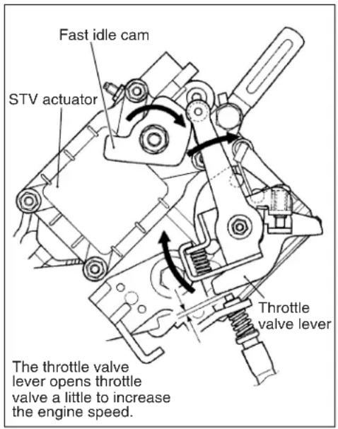
DATA
| Ambient Temp. F | Fast idle rpm | Fast idle cancelling Water Temp. |
| -5 °C(-23 °F) | 1 800 - 2 400 rpm | 50 - 60 °C(122 - 140 °F) |
| 15 °C(59 °F) | 1 700 - 2 300 rpm | 45 - 55 °C(113 - 131 °F) |
| 25 °C(77 °F) | 1 500 - 2 100 rpm | 45 - 55 °C(113 - 131 °F) |
If, under the above conditions, the fast idle cannot be cancelled, the cause may possibly be short-circuit in engine coolant temperature sensor or wiring connections or maladjusted fast idle.
FAST IDLE ADJUTMENT
- Remove the fuel tank and air cleaner box. (4-52 and -60)
- Disconnect the STVA lead wire coupler and turn the ignition switch ON.
- Open the STV gradually with the finger and just when the STP sensor output voltage has become 3.0 V. With the STV held at this position, measure the output voltage of the TP sensor.
- If the TP sensor output voltage is out of specification, turn the fast idle adjusting screw ① and adjust the output voltage to specification (1.158 V).

natural_image
Close-up mechanical assembly showing internal components and a numbered label (①), no readable text or symbols present.DATA
TP sensor output voltage: 1.158 V

09900-25008: Multi circuit tester

Tester knob indication: Voltage (---)
- After adjusting the fast idle speed, set the idle speed to 1 100 – 1 300 rpm by turning the throttle stop screw ②.

natural_image
Close-up of a car engine bay with visible components and a numbered annotation (no text or symbols)THROTTLE VALVE SYNCHRONIZATION
Check and adjust the throttle valve synchronization between two cylinders.

09913-13121: Vacuum balancer gauge
NOTE:
Before balancing the throttle valves, calibrate each vacuum balancer gauge.
- Remove the fuel tank and air cleaner box. (4-52 and -60)
- Remove the rubber caps ① from the vacuum nipples on the respective throttle bodies and connect the vacuum balancer gauge hoses to each vacuum nipple.

- Connect the removed IAT sensor ② and IAP sensor ③.
- Connect the fuel tank and fuel delivery pipe with the fuel feed hose (special tool).

09940-40220: Fuel pressure gauge hose attachment
- Connect the fuel pump lead wire coupler.
- Start up the engine and run it in idling condition for warming up.
- Stop the warmed-up engine.
- Connect a tachometer and start up the engine.
- Bring the engine rpm to 1 200 rpm by the throttle stop screw.
- Check the vacuum of the two cylinders and balance the two throttle valves with the synchronizing screw. (4-66)
NOTE:
* During balancing the throttle valves, always set the engine rpm at 1 200 rpm, using throttle stop screw.
* After balancing the two valves, set the idle rpm to 1 200 rpm.
CAUTION
Avoid drawing dirt into the throttle body while running the engine without air cleaner box. Dirt drawn into the engine will damage the internal engine parts.
For vacuum balancer gauge (09913-13121)
The vacuum gauge is positioned approx. 30° from the horizontal level, and in this position the two balls should be within one ball dia. If the difference is larger than one ball, turn the synchronizing screw on the throttle body and bring the ball to the same level.
A correctly adjusted throttle valve synchronization has the balls in the No.1 and No.2 at the same level.
NOTE:
Make sure that the throttle lever should have a gap Ⓐ (between the throttle lever and throttle lever stopper screw) during synchronization.

Throttle lever gap®: 0.31 mm (0.012 in)

natural_image
Close-up of a mechanical device with a digital multimeter and a tool labeled 'TOOL' (no readable text or symbols on the device itself)
natural_image
Close-up of a mechanical assembly with hoses and components, no visible text or symbols
natural_image
Close-up of a car engine bay with a hand inserting a battery into the charger (no visible text or symbols)
THROTTLE CABLE ADJUSTMENT
NOTE:
Minor adjustment can be made by the throttle grip side adjuster. (2-14)
SENSOR
IAP SENSOR INSPECTION
The intake air pressure sensor is located at the rear side of the air cleaner box. (4-34)
IAP SENSOR REMOVAL/INSTALLATION
- Lift and support the fuel tank. (4-51)
- Remove the IAP sensor ① by removing the screw and disconnect the coupler ② and vacuum hose ③.
• Installation is in the reverse order of removal.
TP SENSOR INSPECTION
- The throttle position sensor is installed on the No.1 throttle body. (4-36)
TP SENSOR REMOVAL/INSTALLATION
- Remove the fuel tank and air cleaner box. (4-52 and -60)
- Remove the TP sensor setting screws ① and disconnect the coupler.
• Install the TP sensor to the No.1 throttle body. Refer to page 4-68 for TP sensor setting procedure.
STP SENSOR INSPECTION
The secondary throttle position sensor is installed on the No.1 throttle body. (4-44)
STP SENSOR REMOVAL/INSTALLATION
- Remove the fuel tank and air cleaner box. (4-52 and -60)
- Remove the STP sensor setting screws ① and disconnect the coupler.
• Install the STP sensor to the No.1 throttle body. Refer to pages 4-67 and -68 for STP sensor setting procedure.


natural_image
Close-up of mechanical components with numbered annotations (1 and 2) and circular features, no readable text or symbols.
natural_image
Mechanical assembly diagram showing components with numbered annotations (no readable text or symbols)CKP SENSOR INSPECTION
The signal rotor is mounted on the generator rotor and crank-shaft position sensor (Pick-up coil) is installed in the generator cover. (4-33)
CKP SENSOR REMOVAL/INSTALLATION
(3-77)

natural_image
Close-up of a mechanical assembly showing gears and housing (no visible text or symbols)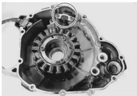
natural_image
Close-up of a mechanical gear assembly with no visible text or symbolsCMP SENSOR INSPECTION
The signal rotor is installed on the No.2 intake camshaft, and the camshaft position sensor (Pick-up coil) is installed on the No.2 cylinder head cover. (4-32)

natural_image
Close-up of a mechanical component with no visible text or symbolsCMP SENSOR REMOVAL/INSTALLATION
- Lift and support the fuel tank. (4-51)
- Disconnect the coupler and remove the CMP sensor. Installation is in the reverse order of removal. (3-34)
IAT SENSOR INSPECTION
The intake air temperature sensor is installed at the rear side of the air cleaner box. (4-39)
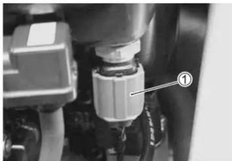
natural_image
Close-up of a mechanical component with a numbered label pointing to a specific part (no readable text or symbols)IAT SENSOR REMOVAL/INSTALLATION
- Lift and support the fuel tank. (4-51)
- Disconnect the IAT sensor coupler ① and remove the IAT sensor from the air cleaner box.
- Installation is in the reverse order of removal.
IAT sensor: 18 N·m (1.8 kgf·m, 13.0 lb·ft)
ECT SENSOR INSPECTION
The engine coolant temperature sensor is installed on the thermostat case. (4-38 and 5-10)
ECT SENSOR REMOVAL/INSTALLATION
(5-10)
AP SENSOR INSPECTION
The atmospheric pressure sensor is located under the seat. (4-40)
AP SENSOR REMOVAL/INSTALLATION
- Remove the seat. (6-4)
- Disconnect the coupler ① and remove the AP sensor.
• Installation is in the reverse order of removal.
TO SENSOR INSPECTION
The tip over sensor is located above the AP sensor. (4-42)
TO SENSOR REMOVAL/INSTALLATION
- Remove the seat. (6-4)
- Disconnect the coupler ① and remove the TO sensor.
• Installation is in the reverse order of removal.
NOTE:
When installing the TO sensor, bring the "UPPER" letter on it to the top.
HO2 SENSOR INSPECTION
The heated oxygen sensor is installed on the exhaust pipe. (4-49)

natural_image
Close-up of an automotive engine component with a highlighted connector (no visible text or symbols)
natural_image
Close-up mechanical assembly showing internal components and a numbered annotation (①), no readable text or symbols present.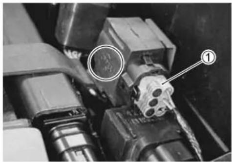
natural_image
Close-up of mechanical components with numbered annotations (1 and 2) pointing to specific parts, no readable text or symbols present.
natural_image
Close-up of mechanical components with a white arrow pointing to a component (no visible text or symbols)HO2 SENSOR REMOVAL/INSTALLATION
- Remove the engine under cover.
- Disconnect the HO 2 sensor lead wire couplers.
- Remove the HO 2 sensor unit.
WARNING
Do not remove the HO2 sensor while it is hot.
CAUTION
Be careful not to expose it to excessive shock. Do not use an impact wrench while removing or installing the HO2 sensor unit. Be careful not to twist or damage the sensor lead wire.
• Installation is in the reverse order of removal.
CAUTION
Do not apply oil or other materials to the sensor air hole.
- Tighten the sensor unit to the specified torque.
H∅SENSOR: 47.5 N·m (4.75 kgf·m, 34.3 lb·ft) - Route the HO 2 sensor lead wire into the frame. (8-16)
- Connect the HO 2 sensor couplers.


natural_image
Close-up of a mechanical assembly with wires and connectors, no visible text or symbols
natural_image
Technical line drawing of a mechanical assembly with a tool inserted (no text or symbols)COOLING AND LUBRICATION SYSTEM
CONTENTS
ENGINE COOLANT 5-2
COOLING CIRCUIT 5-3
COOLING CIRCUIT INSPECTION 5-3
RADIATOR 5-4
REMOVAL 5-4
INSPECTION AND CLEANING 5-5
INSTALLATION 5-6
RADIATOR RESERVOIR TANK 5-6
REMOVAL/INSTALLATION 5-6
RADIATOR CAP 5-6
INSPECTION 5-6
WATER HOSE 5-7
INSPECTION 5-7
COOLING FAN 5-8
REMOVAL 5-8
INSPECTION 5-8
INSTALLATION 5-8
COOLING FAN THERMO-SWITCH 5-9
REMOVAL 5-9
INSPECTION 5-9
INSTALLATION 5-9
ENGINE COOLANT TEMPERATURE SENSOR ....5-10
REMOVAL 5-10
INSPECTION 5-10
INSTALLATION 5-10
THERMOSTAT 5-11
REMOVAL 5-11
INSPECTION 5-11
INSTALLATION 5-12
WATER PUMP 5-13
REMOVAL AND DISASSEMBLY 5-13
INSPECTION 5-15
REASSEMBLY AND INSTALLATION 5-15
LUBRICATION SYSTEM 5-18
OIL PRESSURE 5-18
OIL FILTER 5-18
OIL PRESSURE REGULATOR 5-18
OIL STRAINER 5-18
OIL JET 5-18
OIL PUMP 5-18
OIL PRESSURE SWITCH 5-18
OIL COOLER 5-18
REMOVAL 5-18
INSPECTION AND CLEANING 5-19
INSTALLATION 5-19
ENGINE LUBRICATION FLOW CHART 5-20
ENGINE LUBRICATION CIRCUIT 5-21
ENGINE COOLANT
At the time of manufacture, the cooling system is filled with a 50:50 mixture of distilled water and ethylene glycol anti-freeze. This 50:50 mixture will provide the optimum corrosion protection and excellent heat protection, and will protect the cooling system from freezing at temperatures above -31ircC (-24ircF) . If the motorcycle is to be exposed to temperatures below -31ircC (-24ircF) , this mixing ratio should be increased up to 55% or 60% according to the figure.
CAUTION
* Use a high quality ethylene glycol base anti-freeze, mixed with distilled water. Do not mix an alcohol base anti-freeze and different brands of anti-freeze.
* Do not rut in more than 60% anti-freeze or less than 50%. (Refer to Right figure.)
* Do not use a radiator anti-leak additive.
50% Engine coolant including reserve tank capacity
| Anti-freeze 1 100 ml (2.3/1.9 US/lmp.pt) |
| Water 1 100 ml (2.3/1.9 US/lmp.pt) |
| Anti-freeze density | Freezing point |
| 50% | -31ircC ( -24ircF ) |
| 55% | -40ircC ( -40ircF ) |
| 60% | -55ircC ( -67ircF ) |

line
| Density (%) | Freezing point (°F) | | ----------- | ------------------- | | 0 | 32 | | 20 | 14 | | 40 | -22 | | 60 | -58 | | 80 | -76 | | 100 | -94 |Fig.1 Engine coolant density-freezing point curve.

line
| Density (%) | Boiling point (°F) | Gauge pressure (kgf/cm²) | | ----------- | ------------------ | ------------------------ | | 0 | 100 | 0 | | 10 | 110 | 0.5 | | 20 | 120 | 0.9 | | 30 | 130 | 1.5 | | 40 | 140 | 1.5 | | 50 | 150 | 1.5 | | 60 | 160 | 1.5 |Fig.2 Engine coolant density-boiling point curve.
WARNING
* You can be injured by scalding fluid or steam if you open the radiator cap when the engine is hot. After the engine cools, wrap a thick cloth around cap and carefully remove the cap by turning it a quarter turn to allow pressure to escape and then turn the cap all the way off.
* The engine must be cool before servicing the cooling system.
* Coolant is farmful;
- If the comes in contact with skin or eyes, flush with water.
- If swallowed accidentally, induce vomiting and call physecian immediately.
- Keep it away from chiledren.
COOLING CIRCUIT

flowchart
graph TD
    A["RESERVE TANK"] <--> B["RADIATOR (Upper)"]
    B --> C["RADIATOR (Lower)"]
    C --> D["WATER PUMP"]
    D --> E["NO. 1 CYLINDER HEAD\nNO. 1 CYLINDER"]
    D --> F["NO. 2 CYLINDER\nNO. 2 CYLINDER HEAD"]
    E --> G["THERMOSTAT"]
    F --> G
    G --> H["•"]
    H --> I["•"]
    I --> J["•"]
    J --> K["•"]
    K --> L["•"]
    L --> M["•"]
    M --> N["•"]
    N --> O["•"]
    O --> P["•"]
    P --> Q["•"]
    Q --> R["•"]
    R --> S["•"]
    S --> T["•"]
    T --> U["•"]
    U --> V["•"]
    V --> W["•"]
    W --> X["•"]
COOLING CIRCUIT INSPECTION
Before removing the radiator and draining the engine coolant, inspect the cooling circuit for tightness.
- Remove the cowling. (6-6)
- Remove the radiator cap ① and connect the tester ② to the filler.
WARNING
Do not remove the radiator cap when the engine is hot.
- Give a pressure of about 110 kPa (1.1 kgf/cm², 15.6 psi) and see if the system holds this pressure for 10 seconds.
- If the pressure should fall during this 10-second interval, it means that there is a leaking point in the system. In such a case, inspect the entire system and replace the leaking component or part.
WARNING
When removing the radiator cap tester, put a rag on the filler to prevent spouting of engine coolant.
CAUTION
Do not allow the pressure to exceed the radiator cap release pressure, or the radiator can be damaged.

natural_image
Close-up of a mechanical component with a labeled part (1) and a curved pipe, no visible text or symbols.
natural_image
Close-up of a mechanical valve with a pressure gauge and labeled component (no readable text or symbols)RADIATOR
REMOVAL
- Remove the cowling. (6-6)
- Drain engine coolant. (2-17)
- Disconnect the upper and lower radiator hoses from the radiator.

natural_image
Close-up of a mechanical component with visible wiring and a numbered annotation (no readable text or symbols)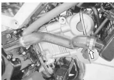
natural_image
Close-up of a mechanical assembly with hoses and gears, no visible text or symbols- Disconnect the siphon hose from the radiator.
- Remove the reservoir tank by removing its mounting bolt.

natural_image
Close-up of a mechanical component with a circular valve and pipe fitting (no visible text or symbols)- Disconnect the horn lead wires.
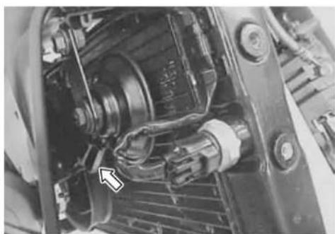
natural_image
Close-up of mechanical components with no visible text or symbols- Disconnect the cooling fan motor and its thermo-switch lead wire coupler ①.
- Remove the radiator by removing its mounting bolts.

natural_image
Mechanical assembly diagram showing two views of a vehicle's engine components with numbered annotations (no readable text or symbols)- With the fasteners unlocked, remove the radiator shroud ①.

natural_image
Close-up of a hand holding a mechanical component with an arrow pointing to a detail (no visible text or symbols)
natural_image
Mechanical device with labeled component (①), no visible text or symbols on the body itself- Remove the cooling fan and horn.
- Remove the cooling fan thermo-switch.
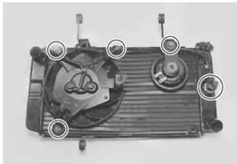
natural_image
Top-down view of a mechanical fan assembly with circular annotations pointing to components (no text or symbols visible)INSPECTION AND CLEANING
- Road dirt or trash stuck to the fins must be removed.
- Use of compressed air is recommended for this cleaning.

natural_image
Close-up of hands installing or adjusting a vehicle's roof panel (no visible text or symbols)- Fins bent down or dented can be repaired by straightening them with the blade of a small screwdriver.
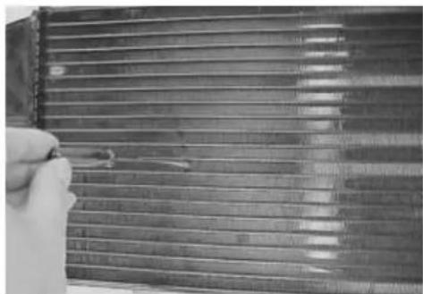
natural_image
Close-up of a hand holding a metallic heat exchanger with visible cooling fins and insulation layers (no text or symbols)INSTALLATION
• Install the cooling fan and horn.

Cooling fan/horn mounting bolt:
8 N·m (0.8 kgf-m, 6.0 lb-ft)
• Install a new O-ring and tigten the cooling fan thermo-switch to the specified torque.

Cooling fan thermo-switch: 17 N·m (1.7 kgf-m, 12.5 lb-ft)
• Install the radiator in the reverse order of removal.
- Route the radiator hoses.
• Install the drain plug with a new sealing washer.
- Pour engine coolant. (2-17)
- Bleed air from the cooling circuit. (2-18)
• Install the cowling.

natural_image
Top-down view of a car radiator with visible cooling fan and mounting bracket (no text or symbols)RADIATOR RESERVOIR TANK REMOVAL/INSTALLATION
- Remove the cowling.
- Disconnect the siphone hose from the radiator.
- Remove the reservoir tank by removing its mouning bolt.
- Drain engine coolant.
• Install the reservoir tank in the reverse order of removal. - Fill the reservoir tank to the upper level.

natural_image
Close-up of a mechanical component with a curved pipe and circular button, no visible text or symbolsRADIATOR CAP INSPECTION
- Remove the cowling.
- Fit the cap ① to the radiator cap tester ②.
- Build up pressure slowly by operating the tester. Make sure that the pressure build-up stops at 95 – 125 kPa (0.95 – 1.25 kgf/cm², 13.5 – 17.8 psi) and that, with the tester held standstill, the cap is capable of holding that pressure for at least 10 seconds.
- Replace the cap if it is found not to satisfy either of these two requirements.


Radiator cap valve opening pressure
Standard: 95 – 125 kPa
(0.95 - 1.25 kgf/cm 2 , 13.5 - 17.8 psi)
WATER HOSE
INSPECTION
- Remove the cowling. (6-6)
- Any water hose found in a cracked condition or flattened or water leaked must be replaced.
- Any leakage from the connecting section should be corrected by proper tightening.
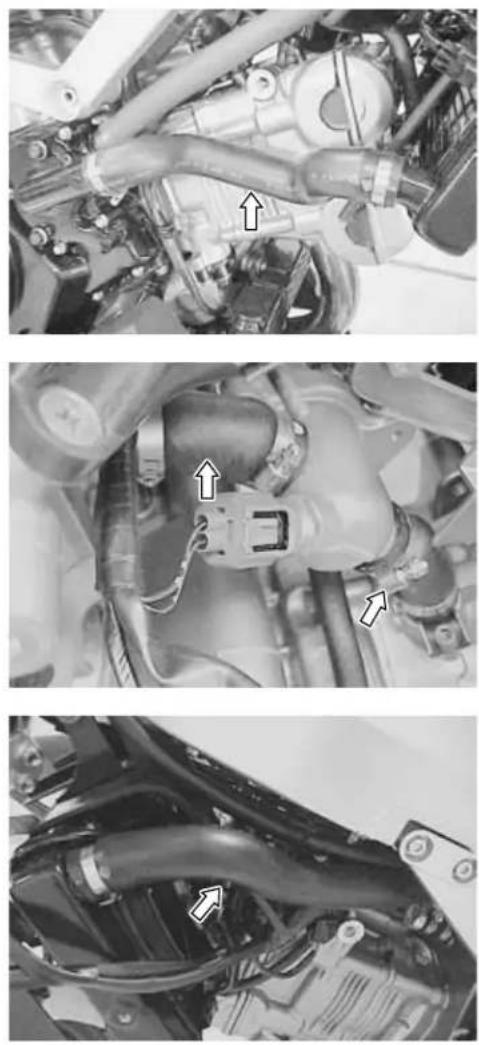
COOLING FAN
REMOVAL
- Remove the cowling. (6-6)
- Drain engine coolant. (2-17)
- Remove the radiator. (5-4)
- Remove the cooling fan.
INSPECTION
- Remove the cowling. (6-6)
- Disconnect the cooling fan motor lead wire coupler ①.
-
Test the cooling fan motor for load current with an ammeter connected as shown in the illustration.
-
The voltmeter is for making sure that the battery applies 12 volts to the motor. With the motor with electric motor fan running at full speed, the ammeter should be indicating not more than 5 amperes.
- If the fan motor does not turn, replace the motor assembly with a new one.
NOTE:
When making above test, it is not necessary to remove the cooling fan.
INSTALLATION
• Install the cooling fan.

Cooling fan motor mounting bolt:
8 N·m (0.8 kgf-m, 6.0 lb-ft)
• Install the radiator.
- Route the radiator hoses. (8-23)
- Pour engine coolant. (2-17)
- Bleed the air from the cooling circuit. (2-18)
• Install the cowling. (6-6)

natural_image
Top-down view of a car fan with visible blades and mounting points (no text or symbols)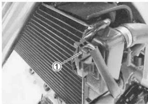
natural_image
Close-up of a car radiator component with a numbered annotation pointing to a specific part (no visible text or symbols)

natural_image
Top-down view of a car radiator fan assembly with mounting holes (no visible text or symbols)COOLING FAN THERMO-SWITCH
REMOVAL
- Remove the cowling. (6-6)
- Drain engine coolant. (2-17)
- Disconnect the cooling fan thermo-switch lead wire coupler ①.
- Remove the cooling fan thermo-switch ②.
INSPECTION
- Check the thermo-switch closing or opening temperatures by testing it at the bench as shown in the figure. Connect the thermo-switch ① to a circuit tester and place it in the oil contained in a pan, which is placed on a stove.
- Heat the oil to raise its temperature slowly and read the column thermometer ② when the switch closes or opens.

09900-25008: Multi circuit tester set

Tester knob indication: Continuity test (•))

Cooling fan thermo-switch operating temperature
Standard (OFF→ON): Approx. 105°C (221°F)
(ON→OFF): Approx. 100°C (212°F)
CAUTION
* Take special care when handling the thermo-switch. It may cause damage if it gets a sharp impact.
* Do not contact the cooling fan thermo-switch① and the column thermometer② with a pan.
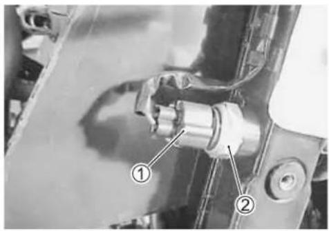
natural_image
Mechanical assembly diagram showing a shaft and mounting bracket with numbered annotations (no readable text or symbols)
INSTALLATION
• Install a new O-ring ①.
- Tighten the cooling fan thermo-switch to the specified torque.

Cooling fan thermo-switch: 17 N·m (1.7 kgf-m, 12.5 lb-ft)
- Pour engine coolant. (2-17)
• Install the cowling. (6-6)
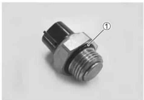
natural_image
Close-up of a metallic mechanical component with threaded end and labeled section (①), no visible text or symbols beyond the label.ENGINE COOLANT TEMPERATURE SENSOR
REMOVAL
- Drain engine coolant. (2-17)
- Remove the seat. (6-4)
- Remove the fuel tank right side cover.
- Remove the IAP sensor vacuum damper.
- Disconnect the engine coolant temperature sensor lead wire coupler.
- Place a rag under the sensor and remove the engine coolant temperature sensor ①.
INSPECTION
- Check the engine coolant temperature by testing it at the bench as shown in the figure. Connect the temperature sensor ① to a circuit tester and place it in the water contained in a pan, which is placed on a stove.
- Heat the water to raise its temperature slowly and read the column thermometer ② and the ohmmeter.
- If the temperature sensor ohmic valve does not change in the proportion indicated, replace it with a new one.
DATA
Temperature sensor specification
| Temperature Standard | resistance |
| 20°C (68°F) Approx. 2 | 45 kΩ |
| 40°C (104°F) Approx. | 1.148 kΩ |
| 60°C (140°F) Approx. | 0.587 kΩ |
| 80°C (176°F) Approx. | 0.322 kΩ |
If the resistance noted to show infinity or too much different resistance value, replace the temperature sensor with a new one.
CAUTION
* Take special care when handling the temperature sensor. It may cause damage if it gets a sharp impact.
* Do not contact the engine coolant temperature sensor ① and the column thermometer ② with a pan.
INSTALLATION
• Install a new sealing washer ①.
- Tighten the engine coolant temperature sensor to the specified torque.

Engine coolant temperature sensor:
18 N·m (1.8 kgf-m, 13.0 lb-ft)
CAUTION
Take special care when handling the temperature sensor. It may cause damage if it gets a sharp impact.
- Pour engine coolant. (2-17)
• Install the fuel tank right side cover. (6-4) - Install the seat.

natural_image
Close-up of an automotive engine component with hoses and valve (no visible text or symbols)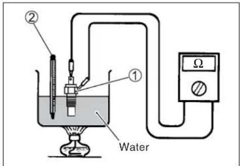
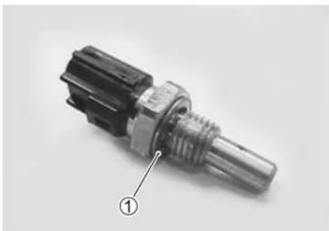
natural_image
Close-up of a mechanical component with a numbered label pointing to a specific part (no visible text or symbols)THERMOSTAT
REMOVAL
- Drain engine coolant. (2-17)
- Place a rag under the thermostat case.
- Remove the thermostat case.
- Remove the thermostat ①.

natural_image
Close-up of mechanical components with circular features, no visible text or symbols
natural_image
Close-up of a mechanical bearing component with a numbered annotation (1) pointing to a circular feature, no visible text or symbols beyond the label.INSPECTION
Inspect the thermostat pellet for signs of cracking.
Test the thermostat at the bench for control action, in the following manner.
• Pass a string between flange, as shown in the photograph.
- Immerse the thermostat in the water contained in a beaker, as shown in the illustration. Note that the immersed thermostat is in suspension. Heat the water by placing the beaker on a stove and observe the rising temperature on a thermometer.
- Read the thermometer just when opening the thermostat. This reading, which is the temperature level at which the thermostat valve begins to open, should be within the standard value.

natural_image
Close-up of a mechanical component with concentric rings and a coiled cable, no visible text or symbols.
DATA
Thermostat valve opening temperature
Standard: Approx. 88 °C (190 °F)
- Keep on heating the water to raise its temperature.
- Just when the water temperature reaches specified value, the thermostat valve should have lifted by at least 8.0 mm (0.31 in).
DATA
Thermostat valve lift
Standard: Over 8.0 mm at 100 °C (Over 0.31 in at 212 °F)
- A thermostat failing to satisfy either of the two requirements (start-to-open temperature and valve lift) must be replaced.
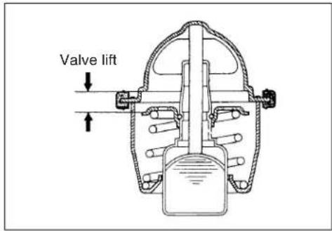
INSTALLATION
• Install the thermostat.
NOTE:
The jiggle valve Ⓐ of the thermostat faces upside.
• Install the thermostat case.
- Tighten the thermostat case bolts to the specified torque.

Thermostat case bolt: 10 N·m (1.0 kgf·m, 7.0 lb·ft)
- Pour engine coolant. (2-17)
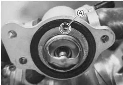
natural_image
Close-up of a mechanical component with labeled point A (no readable text or symbols)
natural_image
Close-up of mechanical components with no visible text or symbolsWATER PUMP
REMOVAL AND DISASSEMBLY
- Remove the engine under cover. (3-3)
- Drain engine coolant. (2-17)
- Drain engine oil. (2-12)
- Remove the right footrest.
- Disconnect the water hoses and crankcase breather hose.
- Remove the water pump case and clutch cover. (3-26)
NOTE:
Before draining engine oil and engine coolant, inspect engine oil and coolant leakage between the water pump and clutch cover. If engine oil is leaking, visually inspect the oil seal and O-ring. If engine coolant is leaking, visually inspect the mechanical seal and seal ring. (5-15)

- Remove the snap ring from the impeller shaft.
- Remove the impeller from the other side.
- Remove the mechanical seal ring ① and the rubber seal ② from the impeller.
- Remove the bearing using the special tool.

09921-20240: Bearing remover set
NOTE:
If there is no abnormal noise, bearing removal is not necessary.
CAUTION
The removed bearing must be replaced with a new one.
- Remove the mechanical seal using the special tool.

09921-20240: Bearing remover set
NOTE:
If there is no abnormal condition, the mechanical seal removal is not necessary.
CAUTION
The removed mechanical seal must be replaced with a new one.
- Remove the oil seal using a suitable bar.
NOTE:
If there is no abnormal condition, the oil seal removal is not necessary.
CAUTION
The removed oil seal must be replaced with a new one.
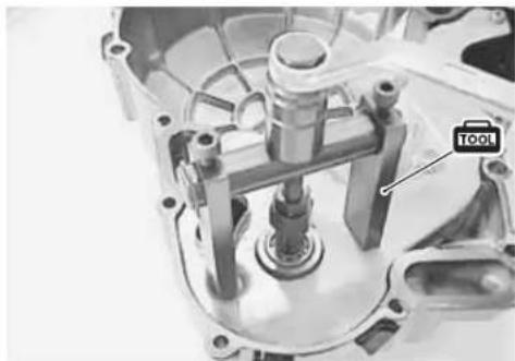
natural_image
Mechanical assembly diagram showing a motor or gear mechanism with no visible text or symbols
natural_image
Mechanical assembly diagram showing internal components with a labeled tool (no readable text or symbols)
natural_image
Close-up of a mechanical component with a metal knob and screw base (no visible text or symbols)INSPECTION
BEARING
- Inspect the play of the bearing by hand while it is in the water pump case.
- Rotate the inner race by hand to inspect for abnormal noise and smooth rotation.
- Replace the bearing if there is anything unusual.
MECHANICAL SEAL
- Visually inspect the mechanical seal for damage, with particular attention given to the sealing face.
- Replace the mechanical seal that shows indications of leakage. Also replace the seal ring if necessary.

natural_image
Close-up of a ball bearing with visible inner and outer rings (no text or symbols)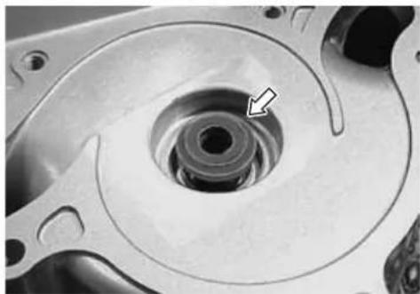
natural_image
Close-up of a mechanical component with concentric rings and a highlighted section (no text or symbols visible)OIL SEAL
- Visually inspect the oil seal for damage, with particular attention given to the lip.
- Replace the oil seal that shows indications of leakage.

natural_image
Close-up of a mechanical component with a circular recess and an arrow pointing to a feature (no text or symbols visible)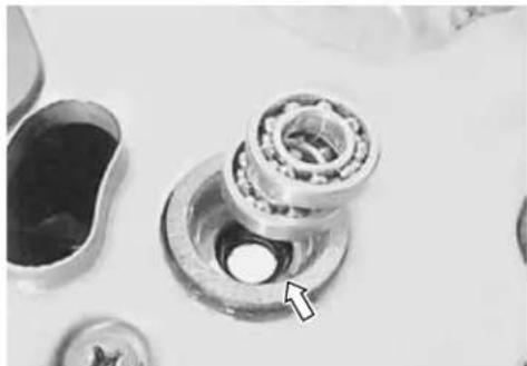
natural_image
Close-up of a mechanical bearing assembly with a highlighted section and an arrow pointing to a component (no visible text or symbols)BEARING CASE
- Visually inspect the bearing case for damage.
- Replace the water pump body if necessary.
REASSEMBLY AND INSTALLATION
• Install the oil seal using the special tool.

09913-70210: Bearing installer set
NOTE:
The stamped mark on the oil seal faces outside.

natural_image
Close-up of a mechanical assembly with a labeled tool (no readable text or symbols beyond the label)- Apply a small quantity of the SUZUKI SUPER GREASE "A" to the oil seal lip.

99000-25030: SUZUKI SUPER GREASE "A" (USA) 99000-25010: SUZUKI SUPER GREASE "A" (Others)
• Install the new mechanical seal using a suitable size socket wrench.
NOTE:
On the new mechanical seal, the sealer Ⓐ has been applied.

natural_image
Close-up of a mechanical component with concentric rings and a labeled section (A), no readable text or symbols present.
natural_image
Close-up of a mechanical component with a labeled section (A) and no visible text or symbols
natural_image
Close-up of a mechanical assembly with a metallic tool inserted, no visible text or symbols• Install the new bearing using the special tool.

09913-70210: Bearing installer set
NOTE:
The stamped mark on the bearing faces crankcase side.
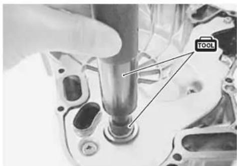
natural_image
Close-up of a mechanical component being inserted into a tool, with no visible text or symbols on the main subject.- Apply grease to the impeller shaft.

99000-25030: SUZUKI SUPER GREASE "A" (USA) 99000-25010: SUZUKI SUPER GREASE "A" (Others)
• Install the rubber seal① into the impeller.
- After wiping off the oily or greasy matter from the mechanical seal ring, install it into the impeller.
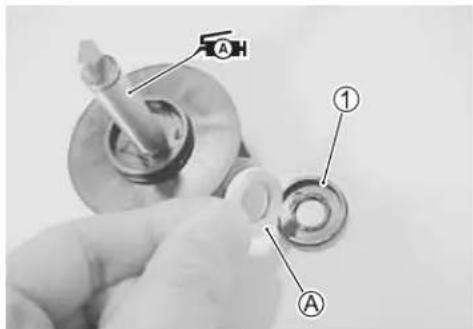
- continued on next page -
NOTE:
The paint marked side Ⓐ of the mechanical seal ring faces the impeller.
• Install the impeller to the water pump body.
• Fix the impeller shaft with the snap ring securely.
• Install a new O-ring ①.
CAUTION
Use a new O-ring to prevent engine coolant leakage.
NOTE:
Apply engine coolant to the O-ring ①.
- Set the impeller shaft end to the cam drive idle shaft. (3-90)
- Connect the water hoses and crankcase breather hose.
• Install the right footrest. - Pour engine coolant. (2-17)
- Pour engine oil. (2-12)
• Install the engine under cover.

natural_image
Close-up of a mechanical pump or turbine component with visible blades and mounting holes (no text or symbols)
natural_image
Close-up of a mechanical component with a central shaft and circular base, showing no visible text or symbols.
natural_image
Mechanical component diagram showing a spiral housing with labeled parts (no readable text or symbols)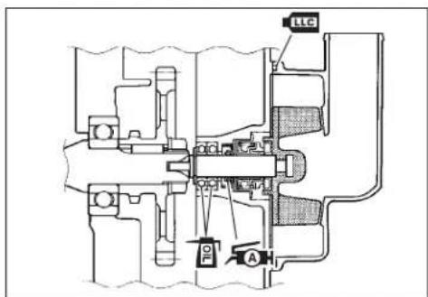
LUBRICATION SYSTEM
OIL PRESSURE
2-30
OIL FILTER
2-13
OIL PRESSURE REGULATOR
3-67
OIL STRAINER
3-29 and -85
OIL JET
3-67, -68 and -94
OIL PUMP
3-66 and -67
OIL PRESSURE SWITCH
3-67 and 7-32
OIL COOLER
REMOVAL
- Remove the engine under cover. (3-3)
- Drain engine oil. (2-12)
- Disconnect the oil cooler hoses.
- Remove the oil cooler.

natural_image
Close-up mechanical assembly showing internal components and a circular detail (no visible text or symbols)
natural_image
Mechanical assembly diagram showing internal components and mounting points (no text or labels visible)- Remove the oil cooler fin guard net.
- Remove the oil hoses.
INSPECTION AND CLEANING
- Inspect the oil cooler and hose joints for oil leakage. If any defect are found, replace the oil cooler and oil hoses with the new ones.
- Road dirt or trash stuck to the fins must be removed.
- Use of compressed air is recommended for this cleaning.
- Fins bent down or dented can be repaired by straightening them with the blade of a small screwdriver.
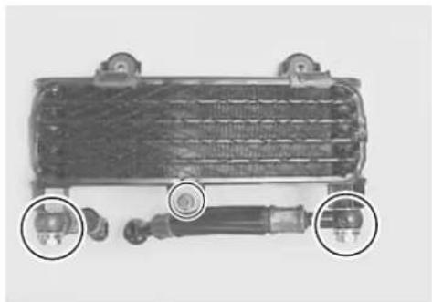
natural_image
Top-down view of a vehicle chassis with attached mechanical components and two circled parts (no visible text or symbols)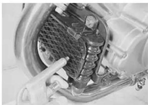
natural_image
Close-up of a mechanical assembly showing internal components and a meshed spring-like structure (no visible text or symbols)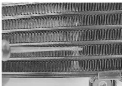
natural_image
Close-up of a coiled metal heating element with no visible text or symbolsINSTALLATION
• Install a new gasket washer ①.
CAUTION
Use a new gasket washer to prevent engine oil leakage.

natural_image
Close-up of mechanical components with no visible text or symbols• Install the oil cooler.
Oil cooler mounting bolt: 10 N·m (1.0 kgf·m, 7.3 lb·ft)
- Tighten the oil cooler hose union bolts to the specified torque.
Oil cooler hose union bolt: 23 N·m (2.3 kgf-m, 16.5 lb-ft)

natural_image
Mechanical assembly diagram showing internal components with no visible text or symbolsENGINE LUBRICATION FLOW CHART

flowchart
```mermaid
graph TD
    subgraph #2_CYLINDER["REAR"]
        A["EX. CAMSHAFT JOURNALS/CAM FACES/SCISSORS GEAR"] --> B["TAPPETS"]
        C["IN. CAMSHAFT JOURNALS/CAM FACES/SCISSORS GEAR"] --> D["TAPPETS"]
        E["IN. CAMSHAFT JOURNALS/CAM FACES/SCISSORS GEAR"] --> F["TAPPETS"]
        G["EX. CAMSHAFT JOURNALS/CAM FACES/SCISSORS GEAR"] --> H["TAPPETS"]
        I["CAM SPROCK-ETS AND DRIVE CHAIN"] --> J["OIL JET"]
        K["#1 PISTON AND PISTON PIN"] --> L["#1 AND #2 CYLINDER WALLS"]
        M["#1 PISTON COOLING NOZZLE"] --> N["#1 AND #2 CRANK-SHAFT PIN BEARINGS"]
        O["#2 PISTON AND PISTON PIN"] --> P["#2 PISTON COOLING NOZZLE"]
        Q["CAM SPROCK-ETS AND DRIVE CHAIN"] --> R["OIL JET"]
        S["CRANKSHAFT LEFT-SIDE JOURNAL BEARING"] --> T["STARTER CLUTCH"]
        U["GENERATOR"] --> V["DRIVESHAFT LEFT-SIDE BEARING"]
        W["DRIVESHAFT GEARS AND BUSHINGS"] --> X["DRIVESHAFT GEARS AND BUSHINGS"]
        Y["STARTER CLUTCH"] --> Z["COUNTERSHAFT LEFT-SIDE BEARING"]
        AA["COUNTERSHAFT GEARS AND BUSHINGS"] --> AB["CLUTCH PLATES"]
        AC["OIL PUMP"] --> AD["OIL SUMP FILTER"]
        AE["OIL PRESSURE REGULATOR"] --> AF["OIL COOLER"]
        AG["OIL FILTER"] --> AH["OIL PRESSURE SWITCH"]
        AI["OIL PRESSURE"] --> AJ["BY-PASS"]
        AK["OIL PRESSURE"] --> AL["BY-PASS"]
    end

    subgraph #2_CYLINDER["FRONT"]
        B --> D
        D --> E
        E --> F
        F --> G
        G --> H
        H --> I
        I --> J
        J --> K
        K --> L
        L --> M
        M --> N
        N --> O
        O --> P
        P --> Q
        Q --> R
        R --> S
        S --> T
        T --> U
        U --> V
        V --> W
        W --> X
        X --> Y
        Y --> Z
        Z --> AA
        AA --> AB
        AB --> AC
        AC --> AD
        AD --> AE
        AE --> AF
        AF --> AG
        AG --> AH
        AH --> AI
    end

    subgraph #2_CYLINDER["REAR"]
        B --> D
        D --> E
        E --> F
        F --> G
        G --> H
        H --> I
        I --> J
        J --> K
        K --> L
        L --> M
        M --> N
        N --> O
        O --> P
        P --> Q
        Q --> R
        R --> S
        S --> T
        T --> U
        U --> V
        V --> X
        X --> Y
        Y --> Z
    end

    subgraph #2_CYLINDER["FRONT"]
        B --> D
        D --> E
        E --> F
        F --> G
        G --> H
        H --> I
        I --> J
        J --> K
        K --> L
        L --> M
        M --> N
        N --> O
        O --> P
        P --> Q
        Q --> R
    end

    subgraph #2_CYLINDER["REAR"]
        B --> D
        D --> E
        E --> F
        F --> G
        G --> H
        H --> I
        I --> J
        J --> K
        K --> L
        L --> M
        M --> N
    end

    subgraph #2_CYLINDER["FRONT"]
        B --> D
        D --> E
        E --> F
        F --> G
        G --> H
    end

    subgraph #2_CYLINDER["REAR"]
        B --> D
        D --> E
        E --> F
    end

    subgraph #2_CYLINDER["FRONT"]
        B --> D
        D --> E
    end

    subgraph #2_CYLINDER["REAR"]
        B --> D
    end

    subgraph #2_CYLINDER["FRONT"]
        B --> D
    end

    subgraph #2_CYLINDER["REAR"]
        B --> D
    end

    subgraph #2_CYLINDER["FRONT"]
        B --> D
    end

    subgraph #2_CYLINDER["REAR"]
        B --> D
    end

    subgraph #2_CYLINDER["FRONT"]
        B --> D
    end

    subgraph #2_CYLINDER["REAR"]
        B --> E
    end

    subgraph #2_CYLINDER["FRONT"]
        B --> E
    end

    subgraph #2_CYLINDER["REAR"]
        B --> F
    end

    subgraph #2_CYLINDER["FRONT"]
        B --> F
    end

    subgraph #2_CYLINDER["REAR"]
        B --> G
    end

    subgraph #2_CYLINDER["FRONT"]
        B --> G
    end

    subgraph #2_CYLINDER["REAR"]
        B --> H
    end

    subgraph #2_CYLINDER["FRONT"]
        B --> H
    end

    subgraph #2_CYLINDER["REAR"]
        B --> I
    end

    subgraph #2_CYLINDER["FRONT"]
        B --> I1["IN. CAMSHAFT JOURNALS/CAM FACES/SCISSORS GEAR"]
    end

    subgraph #2_CYLINDER["REAR"]
            A1["EX. CAMSHAFT JOURNALS/CAM FACES/SCISSORS GEAR"]
            A2["IN. CAMSHAFT JOURNALS/CAM FACES/SCISSORS GEAR"]
            A3["IN. CAMSHAFT JOURNALS/CAM FACES/SCISSORS GEAR"]
            A4["EX. CAMSHAFT JOURNALS/CAM FACES/SCISSORS GEAR"]
            A5["EX. CAMSHAFT JOURNALS/CAM FACES/SCISSORS GEAR"]
            A6["CAM SPROCK-ETS AND DRIVE CHAIN"]
            A7["CAM SPROCK-ETS AND DRIVE CHAIN"]
            A8["CAM SPROCK-ETS AND DRIVE CHAIN"]
            A9["CAM SPROCK-ETS AND DRIVE CHAIN"]
            A10["CAM SPROCK-ETS AND DRIVE CHAIN"]
            A11["CAM SPROCK-ETS AND DRIVE CHAIN"]
            A12["CAM SPROCK-ETS AND DRIVE CHAIN"]
            A13["CAM SPROCK-ETS AND DRIVE CHAIN"]
            A14["CAM SPROCK-ETS AND DRIVE CHAIN"]
            A15["CAM SPROCK-ETS AND DRIVE CHAIN"]
            A16["CAM SPROCK-ETS AND DRIVE CHAIN"]
            A17["CAM SPROCK-ETS AND DRIVE CHAIN"]
            A18["CAM SPROCK-ETS AND DRIVE CHAIN"]
            A19["CAM SPROCK-ETS AND DRIVE CHAIN"]
            A20["CAM SPROCK-ETS AND DRIVE CHAIN"]
            A21["CAM SPROCK-ETS AND DRIVE CHAIN"]
            A22["CAM SPROCK-ETS AND DRIVE CHAIN"]
            A23["CAM SPROCK-ETS AND DRIVE CHAIN"]
            A24["CAM SPROCK-ETS AND DRIVE CHAIN"]
            A25["CAM SPROCK-ETS AND DRIVE CHAIN"]
            A26["CAM SPROCK-ETS AND DRIVE CHAIN"]
            A27["CAM SPROCK-ETS AND DRIVE CHAIN"]
            A28["CAM SPROCK-ETS AND DRIVE CHAIN"]
            A29["CAM SPROCK-ETS AND DRIVE CHAIN"]
            A30["CAM SPROCK-ETS AND DRIVE CHAIN"]
            A31["CAM SPROCK-ETS AND DRIVE CHAIN"]
            A32["CAM SPROCK-ETS AND DRIVE CHAIN"]
            A33["CAM SPROCK-ETS AND DRIVE CHAIN"]
            A34["CAM SPROCK-ETS AND DRIVE CHAIN"]
            A35["CAM SPROCK-ETS AND DRIVE CHAIN"]
            A36["CAM SPROCK-ETS AND DRIVE CHAIN"]
            A37["CAM SPROCK-ETS AND DRIVE CHAIN"]
            A38["CAM SPROCK-ETS AND DRIVE CHAIN"]
            A39["CAM SPROCK-ETS AND DRIVE CHAIN"]
            A40["CAM SPROCK-ETS AND DRIVE CHAIN"]
            A41["CAM SPROCK-ETS AND DRIVE CHAIN"]
            A42["CAM SPROCK-ETS AND DRIVE CHAIN"]
            A43["CAM SPROCK-ETS AND DRIVE CHAIN"]
            A44["CAM SPROCK-ETS AND DRIVE CHAIN"]
            A45["CAM SPROCK-ETS AND DRIVE CHAIN"]
            A46["CAM SPROCK-ETS AND DRIVE CHAIN"]
            A47["CAM SPROCK-ETS AND DRIVE CHAIN"]
            A48["CAM SPROCK-ETS AND DRIVE CHAIN"]
            A49["CAM SPROCK-ETS AND DRIVE CHAIN"]
            A50["CAM SPROCK-ETS AND DRIVE CHAIN"]

    subgraph #2_CYLINDER["REAR"]
        B1["EX. CAMSHAFT JOURNALS/CAM FACES/SCISSORS GEAR"]
            B2["TAPPETS"]
            B3["CAM SHAFT DRIVE IDLE GEAR BUSHING"]
            B4["NIT POTION AND PITTON PIN"]
            B5["#1 PISTON COOLING NOZZLE"]
            B6["#1 AND #2 CYLINDER WALLS"]
            B7["#1 AND #2 CRANK-SHAFT PIN BEARINGS"]
            B8["#2 PISTON COOLING NOZZLE"]
            B9["#2 PISTON COOLING NOZZLE"]
            B10["#2 PISTON COOLING NOZZLE"]
            B11["OIL JET"]
            B12["CRANKSHAFT RIGHT-SIDE JOURNAL BEARING"]
            B13["STARTER CLUTCH"]
            B14["DRIVESHAFT LEFT-SIDE BEARING"]
            B15["DRIVESHAFT GEARS AND BUSHINGS"]
            B16["COUNTERSHAFT LEFT-SIDE BEARING"]
            B17["COUNTERSHAFT GEARS AND BUSHINGS"]
            B18["CLUTCH PLATES"]
            B19["OIL PUMP"]
            B20["OIL SUMP FILTER"]
            B21["OIL PRESSURE REGULATOR"]
            B22["OIL COOLER"]
            B23["OIL FILTER"]
            B24["OIL COOLER"]
            B25["OIL PRESSURE SWITCH"]
            B26["OIL PRESSURE SWITCH"]
            B27["OIL PRESSURE SWITCH"]
            B28["OIL PRESSURE SWITCH"]
            B29["OIL PRESSURE SWITCH"]
            B30["OIL PRESSURE SWITCH"]
            B31["OIL PRESSURE SWITCH"]
            B32["OIL PRESSURE SWITCH"]
            B33["OIL PRESSURE SWITCH"]
            B34["OIL PRESSURE SWITCH"]
            B35["OIL PRESSURE SWITCH"]
            B36["OIL PRESSURE SWITCH"]
            B37["OIL PRESSURE SWITCH"]
            B38["OIL PRESSURE SWITCH"]
            B39["OIL PRESSURE SWITCH"]
            B40["OIL PRESSURE SWITCH"]
            B41["OIL PRESSURE SWITCH"]
            B42["OIL PRESSURE SWITCH"]
            B43["OIL PRESSURE SWITCH"]
            B44["OIL PRESSURE SWITCH"]
            B45["OIL PRESSURE SWITCH"]
            B46["OIL PRESSURE SWITCH"]
            B47["OIL PRESSURE SWITCH"]
            B48["OIL PRESSURE SWITCH"]
            B49["OIL PRESSURE SWITCH"]
            B50["OIL PRESSURE SWITCH"]
            B51["OIL PRESSURE SWITCH"]
            B52["OIL PRESSURE SWITCH"]
            B53["OIL PRESSURE SWITCH"]
            B54["OIL PRESSURE SWITCH"]
            B55["OIL PRESSURE SWITCH"]
            B56["OIL PRESSURE SWITCH"]
            B57["OIL PRESSURE SWITCH"]
            B58["OIL PRESSURE SWITCH"]
            B59["OIL PRESSURE SWITCH"]
            B60["OIL PRESSURE SWITCH"]
            B61["OIL PRESSURE SWITCH"]
            B62["OIL PRESSURE SWITCH"]
            B63["OIL PRESSURE SWITCH"]
            B64["OIL PRESSURE SWITCH"]
            B65["OIL PRESSURE SWITCH"]
            B66["OIL PRESSURE SWITCH"]
            B67["OIL PRESSURE SWITCH"]
            B68["OIL PRESSURE SWITCH"]
            B69["OIL PRESSURE SWITCH"]
            B70["OIL PRESSURE SWITCH"]
            B71["OIL PRESSURE SWITCH"]
            B72["OIL PRESSURE SWITCH"]
            B73["OIL PRESSURE SWITCH"]
            B74["OIL PRESSURE SWITCH"]
            B75["OIL PRESSURE SWITCH"]
            B76["OIL PRESSURE SWITCH"]
            B77["OIL PRESSURE SWITCH"]
            B78["OIL PRESSURE SWITCH"]
            B79["OIL PRESSURE SWITCH"]
            B80["OIL PRESSURE SWITCH"]
            B81["OIL PRESSURE SWITCH"]
            B82["OIL PRESSURE SWITCH"]
            B83["OIL PRESSURE SWITCH"]
            B84["OIL PRESSURE SWITCH"]
            B85["OIL PRESSURE SWITCH"]
            B86["OIL PRESSURE SWITCH"]
            B87["OIL PRESSURE SWITCH"]
            B88["OIL PRESSURE SWITCH"]
            B89["OIL PRESSURE SWITCH"]
            B90["OIL PRESSURE SWITCH"]
            B91["OIL PRESSURE SWITCH"]
          end

    subgraph #2_CYLINDER["REAR"]
        C1["CRANKSHAFT LEFT-SIDE JOURNAL BEARING"]
    end

    subgraph #2_CYLINDER["REAR"]
        C2["DRAIVERSHAFT LEFT-SIDE BEARING"]
      end

    subgraph #2_CYLINDER["REAR"]
        C3["DOUNTERSHAFT LEFT-SIDE BEARING"]
      end

    subgraph #2_CYLINDER["REAR"]
        C4["DOUNTERSHAFT LEFT-SIDE BEARING"]
      end

    subgraph #2_CYLINDER["REAR"]
        C5["DOUNTERSHAFT LEFT-SIDE BEARING"]
      end

    subgraph #2_CYLINDER["REAR"]
        C6["DOUNTERSHAFT LEFT-SIDE BEARING"]
      end

    subgraph #2_CYLINDER["REAR"]
        C7["DOUNTERSHAFT LEFT-SIDE BEARING"]
      end

    subgraph #2_CYLINDER["REAR"]
        C8["DOUNTERSHAFT LEFT-SIDE BEARING"]
      end

    subgraph #2_CYLINDER["REAR"]
        C9["DOUNTERSHAFT LEFT-SIDE BEARING"]
      end

    subgraph #2_CYLINDER["REAR"]
        C10["DOUNTERSHAFT LEFT-SIDE BEARING"]
      end

    subgraph #2_CYLINDER["REAR"]
        C11["DOUNTERSHAFT LEFT-SIDE BEARING"]
      end

    subgraph #2_CYLINDER["REAR"]
        C12["DOUNTERSHAFT LEFT-SIDE BEARING"]
      end

    subgraph #2_CYLINDER["REAR"]
        C13["DOUNTERSHAFT LEFT-SIDE BEARING"]
      end

    subgraph #2_CYLINDER["REAR"]
        C14["DOUNTERSHAFT LEFT-SIDE BEARING"]
      end

    subgraph #2_CYLINDER["REAR"]
        C15["DOUNTERSHAFT LEFT-SIDE BEARING"]
      end

    subgraph #2_CYLINDER["REAR"]
        C16["DOUNTERSHAFT LEFT-SIDE BEARING"]
      end

    subgraph #2_CYLINDER["REAR"]
        C17["DOUNTERSHAFT LEFT-SIDE BEARING"]
      end

    subgraph #2_CYLINDER["REAR"]
        C18["DOUNTERSHAFT LEFT-SIDE BEARING"]
      end

    subgraph #2_CYLINDER["REAR"]
        C19["DOUNTERSHAFT LEFT-SIDE BEARING"]
      end

    subgraph #2_CYLINDER["REAR"]
        C20["DOUNTERSHAFT LEFT-SIDE BEARING"]
      end

    subgraph #2_CYLINDER["REAR"]
        C21["DOUNTERSHAFT LEFT-SIDE BEARING"]
      end

    subgraph #2_CYLINDER["REAR"]
        C22["DOUNTERSHAFT LEFT-SIDE BEARING"]
      end

    subgraph #2_CYLINDER["REAR"]
        C23["DOUNTERSHAFT LEFT-SIDE BEARING"]
      end

    subgraph #2_CYLINDER["REAR"]
        C24["DOUNTERSHAFT LEFT-SIDE BEARING"]
      end

    subgraph #2_CYLINDER["REAR"]
        C25["DOUNTERSHAFT LEFT-SIDE BEARING"]
      end

    subgraph #2_CYLINDER["REAR"]
        C26["DOUNTERSHAFT LEFT-SIDE BEARING"]
      end

    subgraph #2_CYLINDER["REAR"]
        C27["DOUNTERSHAFT LEFT-SIDE BEARING"]
      end

    subgraph #2_CYLINDER["REAR"]
        C28["DOUNTERSHAFT LEFT-SIDE BEARING"]
      end

    subgraph #2_CYLINDER["REAR"]
        C29["DOUNTERSHAFT LEFT-SIDE BEARING"]
      end

    subgraph #2_CYLINDER["REAR"]
        C30["DOUNTERSHAFT LEFT-SIDE BEARING"]
      end

    subgraph #2_CYLINDER["REAR"]
        C31["DOUNTERSHAFT LEFT-SIDE BEARING"]
      end

    subgraph #2_CYLINDER["REAR"]
        C32["DOUNTERSHAFT LEFT-SIDE BEARING"]
      end

    subgraph #2_CYLINDER["REAR"]
        C33["DOUNTERSHAFT LEFT-SIDE BEARING"]
      end

    subgraph #2_CYLINDER["REAR"]
        C34["DOUNTERSHAFT LEFT-SIDE BEARING"]
      end

    subgraph #2_CYLINDER["REAR"]
        C35["DOUNTERSHAFT LEFT-SIDE BEARING"]
      end

    subgraph #2_CYLINDER["REAR"]
        C36["DOUNTERSHAFT LEFT-SIDE BEARING"]
      end

    subgraph #2_CYLINDER["REAR"]
        C37["DOUNTERSHAFT LEFT-SIDE BEARING"]
      end

    subgraph #2_CYLINDER["REAR"]
        C38["DOUNTERSHAFT LEFT-SIDE BEARING"]
      end

    subgraph #2_CYLINDER["REAR"]
        C39["DOUNTERSHAFT LEFT-SIDE BEARING"]
      end

    subgraph #2_CYLINDER["REAR"]
        C40["DOUNTERSHAFT LEFT-SIDE BEARING"]
      end

    subgraph #2_CYLINDER["REAR"]
        C41["DOUNTERSHAFT LEFT-SIDE BEARING"]
      end

    subgraph #2_CYLINDER["REAR"]
        C42["DOUNTERSHAFT LEFT-SIDE BEARING"]
      end

    subgraph #2_CYLINDER["REAR"]
        C43["DOUNTERSHAFT LEFT-SIDE BEARING"]
      end

    subgraph #2_CYLINDER["REAR"]
        C44["DOUNTERSHAFT LEFT-SIDE BEARING"]
      end

    subgraph #2_CYLINDER["REAR"]
        C45["DOUNTERSHAFT LEFT-SIDE BEARING"]
ENGINE LUBRICATION CIRCUIT
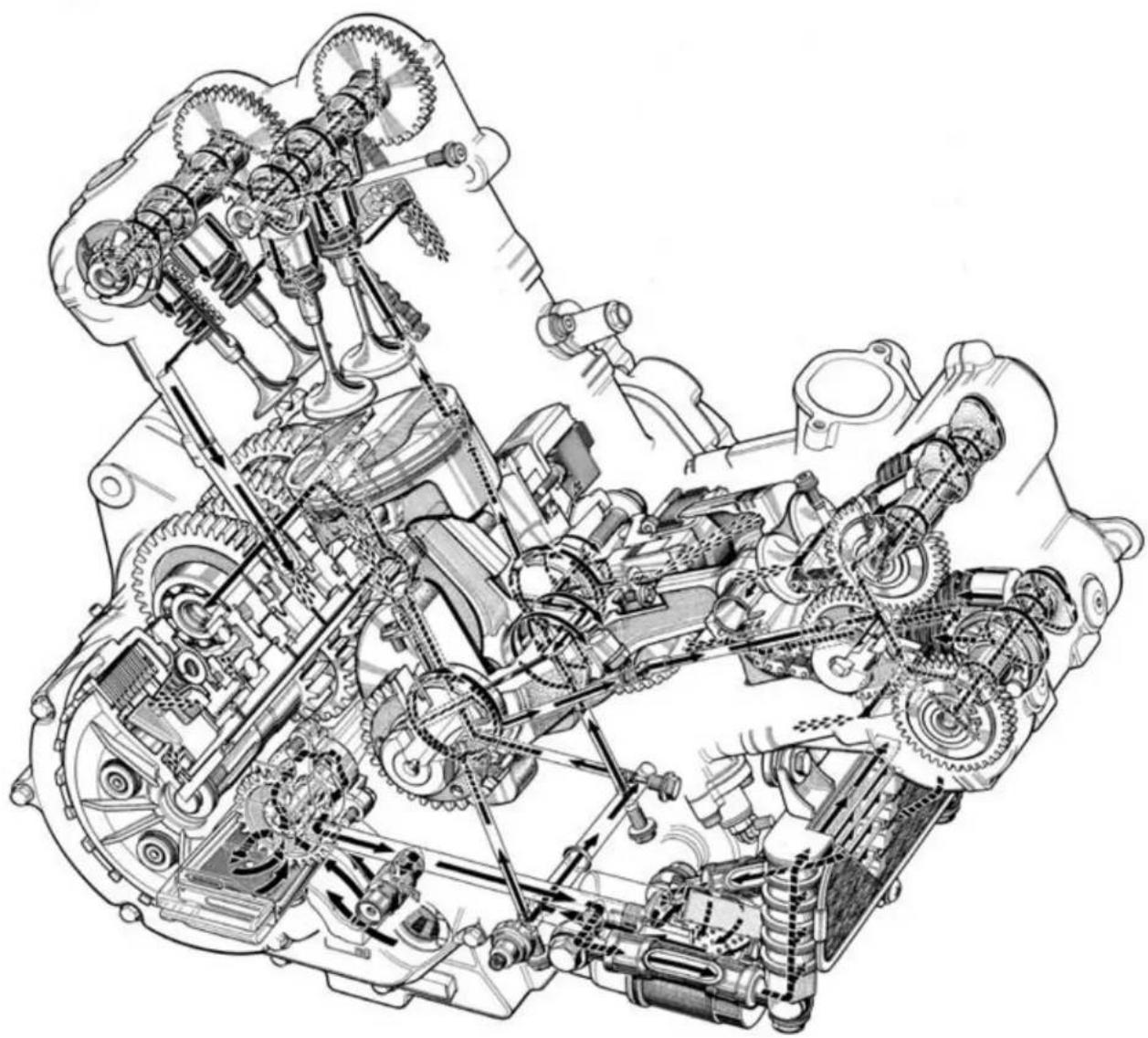
natural_image
Technical line drawing of a mechanical assembly with gears and linkages (no text or labels)CHASSIS
CONTENTS
EXTERIOR PARTS ....6-2 CONSTRUCTION ....6-2 REMOVAL ....6-4
FRONT WHEEL 6-8 CONSTRUCTION 6-8 REMOVAL 6-9 INSPECTION AND DISASSEMBLY 6-9 REASSEMBLY AND REMOUNTING 6-11
FRONT FORK 6-14 CONSTRUCTION 6-14 REMOVAL AND DISASSEMBLY 6-15 INSPECTION 6-18 REASSEMBLY AND REMOUNTING 6-19
STEERING AND HANDLEBAR ....6-24 CONSTRUCTION ....6-24 REMOVAL ....6-25 INSPECTION AND DISASSEMBLY ....6-28 REASSEMBLY AND REMOUNTING ....6-29 STEERING TENSION ADJUSTMENT ....6-32
REAR WHEEL 6-33 CONSTRUCTION 6-33 REMOVAL 6-34 INSPECTION AND DISASSEMBLY 6-35 REASSEMBLY AND REMOUNTING 6-38
REAR SHOCK ABSORBER 6-42 CONSTRUCTION 6-42 REMOVAL 6-43 INSPECTION 6-44 REAR SHOCK ABSORBER DISPOSAL 6-44 REMOUNTING 6-45 SUSPENSION SETTING 6-46
REAR SWINGARM 6-47 CONSTRUCTION 6-47 REMOVAL 6-48 INSPECTION AND DISASSEMBLY 6-49 REASSEMBLY 6-52 REMOUNTING 6-54 FINAL INSPECTION AND ADJUSTMENT 6-55
FRONT BRAKE ....6-56 CONSTRUCTION ....6-56 BRAKE PAD REPLACEMENT ....6-57 BRAKE FLUID REPLACEMENT ....6-58 CALIPER REMOVAL AND DISASSEMBLY ....6-5 CALIPER INSPECTION ....6-60 CALIPER REASSEMBLY AND REMOUNTING ....6-61 BRAKE DISC INSPECTION ....6-62 MASTER CYLINDER REMOVAL AND DISASSEMBLY ....6-63 MASTER CYLINDER INSPECTION ....6-64 MASTER CYLINDER REASSEMBLY AND REMOUNTING ....6-6
REAR BRAKE 6-66 CONSTRUCTION 6-66 BRAKE PAD REPLACEMENT 6-67 BRAKE FLUID REPLACEMENT 6-68 CALIPER REMOVAL AND DISASSEMBLY 6-69 CALIPER INSPECTION 6-70 BRAKE DISC INSPECTION 6-71 CALIPER REASSEMBLY AND REMOUNTING 6-72 MASTER CYLINDER REMOVAL AND DISASSEMBLY 6-73 MASTER CYLINDER INSPECTION 6-74 MASTER CYLINDER REASSEMBLY AND REMOUNTING 6-75
CLUTCH RELEASE CYLINDER AND MASTER CYLINDER 6-77 CONSTRUCTION 6-77 CLUTCH FLUID REPLACEMENT 6-78 CLUTCH RELEASE CYLINDER REMOVAL AND DISASSEMBLY 6-79 CLUTCH RELEASE CYLINDER INSPECTION 6-70 CLUTCH RELEASE CYLINDER REASSEMBLY AND REMOUNTING 6-71 CLUTCH MASTER CYLINDER REMOVAL AND DISASSEMBLY 6-80 CLUTCH MASTER CYLINDER INSPECTION 6-82 CLUTCH MASTER CYLINDER REASSEMBLY AND REMOUNTING 6-83
TIRE AND WHEEL 6-84 TIRE REMOVAL 6-84 INSPECTION 6-84 VALVE INSTALLATION 6-85 TIRE INSTALLATION 6-85
EXTERIOR PARTS CONSTRUCTION
① Screen
② Cowling brace
③ Fuel tank top cover
④ Combination meter panel
⑤ Cowling body
⑥ Right cowling
⑦ Left cowling
⑧ Left side cowling
⑨ Right side cowling
⑩ Inner cowling
⑪ Engine under cover
Ⓐ Cowling brace mounting bolt

U
| ITEM N·m kgf-m lb-ft | ||||
| A | 35 | 3.5 | 25.5 | |
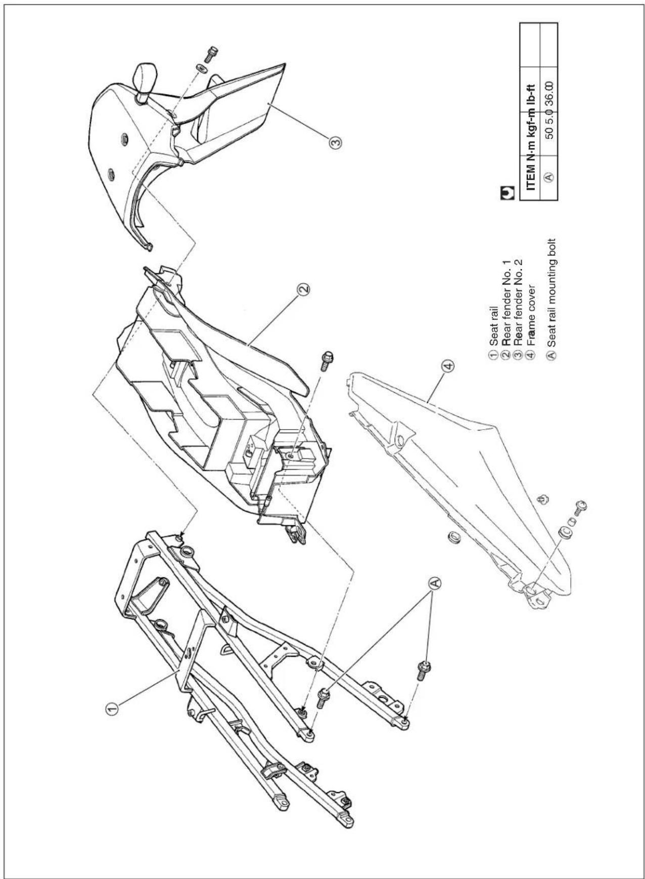
REMOVAL
SEAT
- Remove the seat with the ignition key.
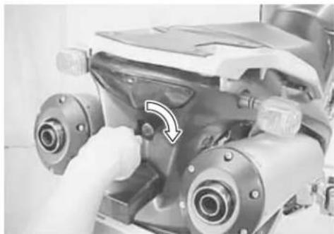
natural_image
Close-up of a mechanical component with a hand adjusting parts, showing a curved arrow indicating rotation (no text or symbols visible)
natural_image
Side view of a motorcycle with visible seat and side panel, no text or symbols presentFRONT TANK COVERS
- Remove the seat. (Above)
- Remove the fuel tank side cover mounting secrew.
- Remove thefuel tank side cover by pulling on the hooked parts.

natural_image
Close-up of a motorcycle's side profile with star markers highlighting key points (no text or symbols present)☆: hooked part

natural_image
Close-up of a robotic car's head and legs with star-shaped markers (no text or symbols visible)CARRIER
- Remove the seat. (Above)
- Remove the carrier.

natural_image
Top-down view of a car chassis with visible internal components and mounting holes (no text or symbols)FRAME COVERS
- Remove the seat. (6-4)
- Remove the carrier. (6-4)
- Remove the fuel tank cover. (6-4)
- Remove the screw ① and clip ②.
- Remove the frame cover by pulling on the hooked part.
☆: hooked part

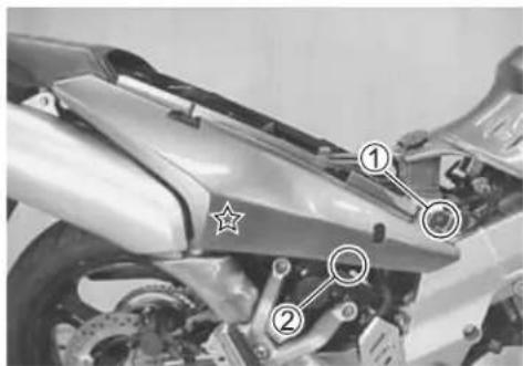
REAR FENDER
- Remove the seat. (6-4)
- Remove the carrier. (6-4)
- Remove the bolts.

natural_image
Close-up of a mechanical component with a circular detail and bolted features (no visible text or symbols)
natural_image
Close-up of a mechanical assembly with no visible text or symbols- Disconnect the brake light/taillight lead wire coupler.

natural_image
Close-up of a mechanical component with an arrow pointing to a feature (no visible text or symbols)COWLING AND COWLING BRACE
- Remove the screen by removing two screws.
- Remove the fuel tank top cover ① by removing the fasteners.
- Remove the combination cover mounting screws.
- Remove the combination meter panel ② by removing the fasteners.
- Remove the cowling inner cover ③ by removing two screws and eight fasteners.
- Remove the left cowling ④.
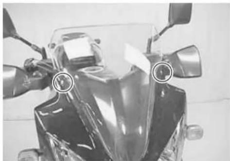
natural_image
Front view of a motorcycle with visible headlights and front brackets (no text or symbols)
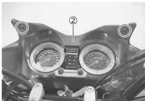
natural_image
Close-up of a motorcycle's front wheel and dashboard with dual gauges (no visible text or symbols)
natural_image
Close-up of a car engine compartment with numbered annotations (3 and 1) pointing to internal components, no readable text or symbols present.
- Remove the right cowling ⑤.
- Remove the turn signals.
- Remove the cowling body ⑥.
- Disconnect the couplers.
- Remove the cowling blace ⑦.
- Remove the combination meter. (7-22)


natural_image
Front view of a motorcycle head with illuminated headlights and circular annotations (no readable text or symbols)
natural_image
Close-up of a motorcycle's front wheel assembly with visible mechanical components and a black arrow pointing to a detail (no text or symbols)
natural_image
Mechanical assembly diagram showing two circular components labeled ① and ②, with no visible text or symbols beyond labels.FRONT WHEEL CONSTRUCTION


| ITEM | N·m | kgf-m | lb-ft | |
| A | 100 | 10.0 | 72.5 | |
| B | 23 | 2.3 | 16.5 |
REMOVAL
- Remove the right and left brake calipers ①.
- Loosen two axle pinch bolts ② on the right front fork leg.
CAUTION
Do not operate the brake lever while removing the calipers.
- Slightly loosen the front axle by using the special tool.

09944-28320: Hexagon bit 19 mm
- Raise the front wheel off the ground and support the motorcycle with a jack or a wooden block.
- Remove the front axle and the front wheel.
- Remove the spacer ③.
NOTE:
After removing the front wheel, fit the calipers temporarily to the original positions.
INSPECTION AND DISASSEMBLY
TIRE (6-84)
BRAKE DISC (6-62)
- Remove the brake discs.
DUST SEAL
- Inspect the dust seals lip for wear or damage. If any damages are found, replace the dust seals with new ones.
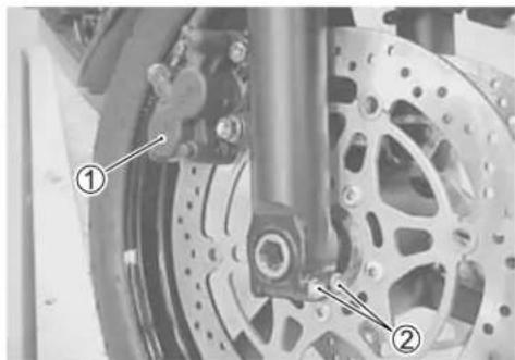
natural_image
Close-up of a mechanical assembly with labeled components (no readable text or symbols)
natural_image
Close-up of a car brake system with a tool labeled 'TOOL' (no other text or symbols visible)
natural_image
Close-up of a car wheel rim with a labeled component (③) and bolt holes, no readable text or symbols beyond the number.
natural_image
Close-up of a car brake disc with multiple brake calipers and mounting holes (no text or symbols visible)
natural_image
Close-up of a metallic mechanical component with a central bore and an arrow pointing to a hole (no text or symbols visible)- Remove the dust seal by using the oil seal remover.

09913-50121: Oil seal remover
CAUTION
Do not reuse the removed dust seals.
FRONT AXLE
Using a dial gauge, check the front axle for runout and replace it if the runout exceeds the limit.

09900-20607: Dial gauge (1/100)
09900-20701: Magnetic stand
09900-21304: V-block set (100 mm)

Axle shaft runout
Service Limit: 0.25 mm (0.010 in)
WHEEL
Make sure that the wheel runout checked as shown does not exceed the service limit. An excessive runout is usually due to worn or loosened wheel bearings and can be reduced by replacing the bearings. If bearing replacement fails to reduce the runout, replace the wheel.
(Wheel inspection: 6-84)

Wheel runout
Service Limit (Axial and Radial): 2.0 mm (0.08 in)
WHEEL BEARING
Inspect the play of the wheel bearings by finger while they are in the wheel. Rotate the inner race by finger to inspect for abnormal noise and smooth rotation.
Replace the bearing in the following procedure if there is anything unusual.
- Remove the wheel bearings by using the special tool.

09921-20240: Bearing remover set
CAUTION
Do not reuse the removed bearings.

natural_image
Close-up of a mechanical assembly with a tool labeled 'TOOL' pointing to a central component (no other text or symbols visible)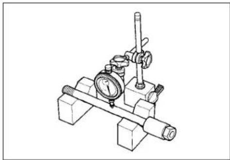
natural_image
Technical line drawing of a mechanical device with pressure gauge and lever (no text or symbols)
natural_image
Technical line drawing of two pressure gauges on a curved surface (no text or symbols)
natural_image
Line drawing of a hand pressing down on a ball bearing (no text or symbols)
natural_image
Close-up of a mechanical assembly with a tool labeled 'TOOL' and a hand holding the wheel (no readable text or symbols beyond label)REASSEMBLY AND REMOUNTING
Reassemble and remount the front wheel in the reverse order of removal and disassembly. Pay attention to the following points:
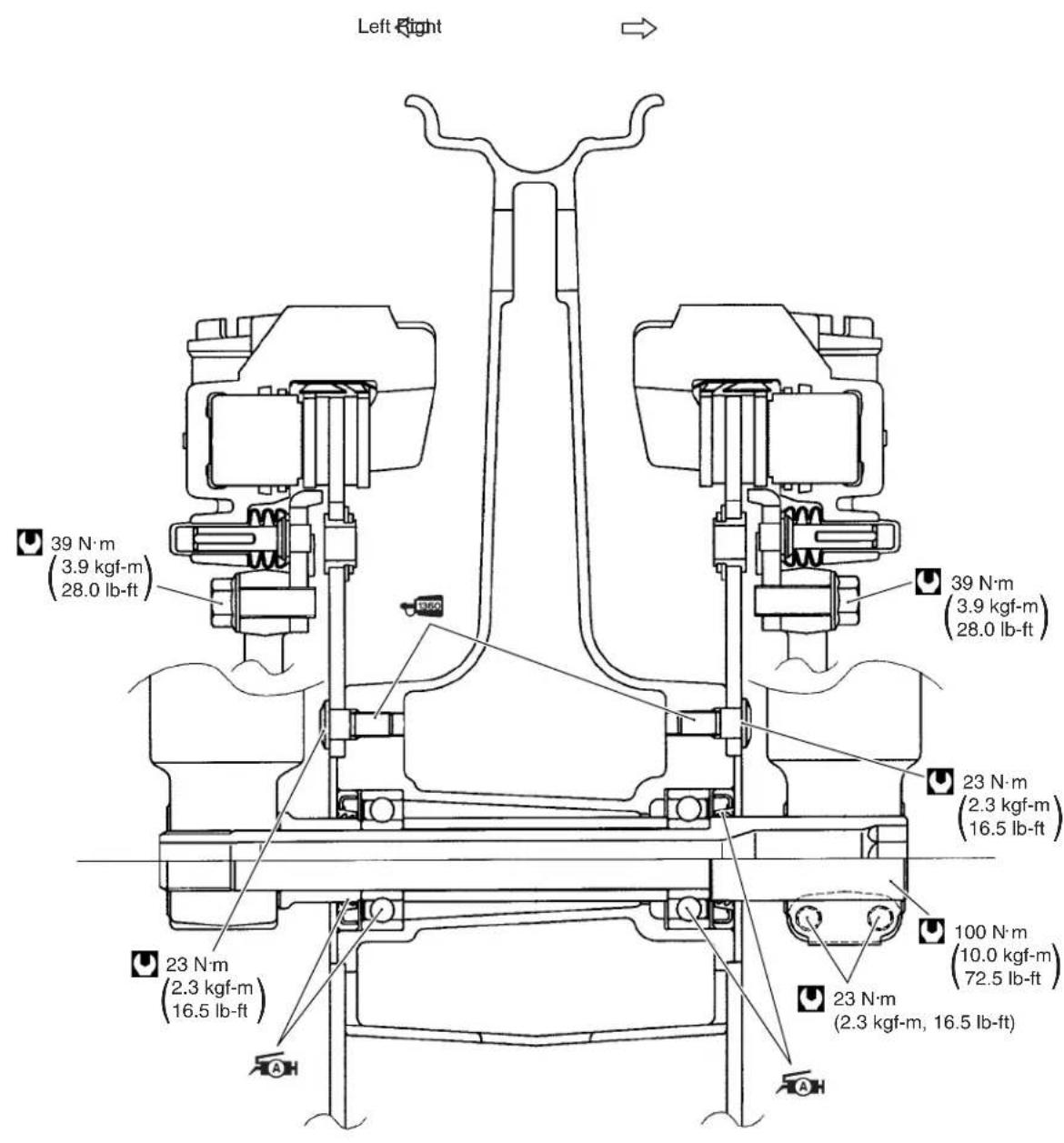
WHEEL BEARING
- Apply grease to the wheel bearings.

99000-25030: SUZUKI SUPER GREASE "A" (USA) 9000-25010: SUZUKI SUPER GREASE "A" (Others)
- First install the left wheel bearing, then install the right wheel bearing and spacer by using the special tools.

09941-34513: Bearing/Steering race installer set
CAUTION
The sealed cover of the bearing must face outside.

natural_image
Line drawing of hands holding a cylindrical object with a lid, next to a container (no text or symbols visible)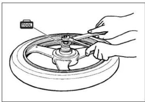

BRAKE DISC
Make sure that the brake disc is clean and free of any greasy matter.
- Apply THREAD LOCK SUPER "1360" to the disc mounting bolts and tighten them to the specified torque.

Brake disc bolt: 23 N·m (2.3 kgf-m, 16.5 lb-ft)

99000-32130: THREAD LOCK SUPER "1360"

natural_image
Close-up of a car brake disc with multiple brake pads and mounting holes (no text or symbols visible)WHEEL
Install the front wheel with the front axle and tighten the front axle temporarily.
WARNING
The directional arrow on the wheel must point to the wheel rotation, when remounting the wheel.
BRAKE CALIPER
- Tighten the brake caliper mounting bolts to the specified torque.

Front brake caliper mounting bolt:
39 N·m (3.9 kgf-m, 28.0 lb-ft)
NOTE:
Push the pistons all the way into the caliper and remount the calipers.
FRONT AXLE
- Tighten the front axle to the specified torque with special tool.

09944-28320: Hexagon bit 19 mm

Front axle: 100 N·m (10.0 kgf-m, 72.5 lb-ft)
NOTE:
Before tightening the two axle pinch bolts on the right front fork leg, move the front fork up and down 4 or 5 times without applying front brake.
- Tighten two axle pinch bolts on the right front fork leg to the specified torque.

Front axle pinch bolt: 23 N·m (2.3 kgf·m, 16.5 lb·ft)
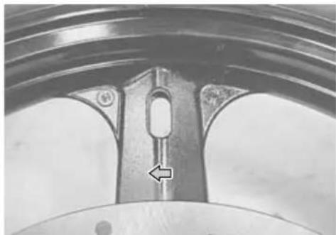
natural_image
Close-up of a mechanical component with a central hole and arrow indicator (no text or symbols)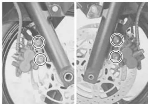
natural_image
Close-up of two mechanical components with circular annotations highlighting features (no readable text or symbols)
natural_image
Close-up of a silver motorcycle wheel and brake system (no visible text or symbols)
natural_image
Close-up of a car brake wheel and tire assembly (no visible text or symbols)FRONT FORK CONSTRUCTION
① O-ring
② Washer
③ Spacer
④ Spring
⑤ Inner rod/damper rod (cartridge)
⑥ Inner tube
⑦ Slide metal
⑧ Gasket
⑨ Dust seal
⑩ Oil seal stopper ring
⑪ Oil seal
⑫ Oil seal retainer
⑬ Guide metal
⑭ Oil lock piece
⑮ Outer tube
Ⓐ Front fork cap bolt
⑧ Inner rod lock nut
© Front axle pinch bolt
D Damper rod bolt

U
| ITEM N·m kgf·m lb·ft | |||
| A | 23 2.3 | 16.5 | |
| B | 20 2.0 | 14.5 | |
| C | 23 2.3 | 16.5 | |
| D | 20 2.0 | 14.5 | |
REMOVAL AND DISASSEMBLY
- Remove the front wheel. (6-9)
- Remove the front fender bolt ① and brake hose bolt ②.
- Loosen the front fork upper clamp bolts ③.
NOTE:
Slightly loosen the front fork cap bolts ④ before loosening the lower clamp bolts to facilitate later disassembly.
- Loosen the front fork lower clamp bolts.
NOTE:
Hold the front fork by the hand to prevent sliding out of the steering stem.
- Loosen and remove the front fork cap bolt.
- Remove the spacer ⑤, washer ⑥ and spring ⑦.


natural_image
Close-up of industrial pipe fittings with a magnified inset showing internal components (no visible text or symbols)
natural_image
Close-up of a metallic kitchen sink with a coiled spring and handle (no text or symbols visible)
- Invert the fork and drain the fork oil out of the fork by stroking.
- Hold the fork inverted for a few minutes to drain oil.
- Remove the front axle pinch bolts.
- Remove the damper rod bolt ⑧.
- Remove the damper rod.
NOTE:
If the damper rod turns together with the damper rod bolt, temporarily install the fork spring, spacer, washer and cap bolt to prevent the damper rod from turning.
- Remove the oil lock piece ⑨ and rebound spring ⑩.
CAUTION
Do not attempt to disassemble the damper rod. It is unserviceable.
- Drain the fork oil out of damper rod by pumping the rod.

natural_image
Hand holding a metal rod inside a stainless steel tray, with an arrow pointing to the drain (no text or symbols visible)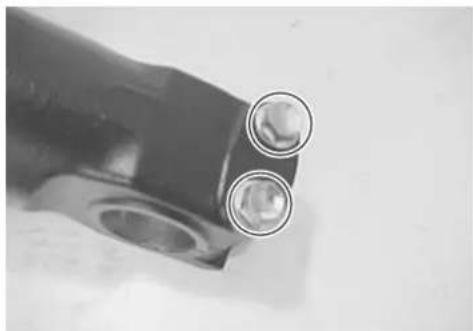
natural_image
Close-up of a mechanical component with two circular features, no visible text or symbols
natural_image
Close-up of a mechanical component with a screwdriver inserted, showing a circular opening and a numbered callout (no text or symbols visible)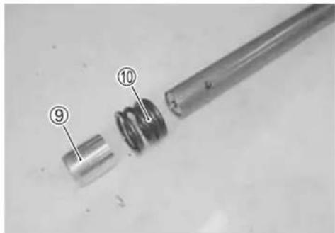
natural_image
Close-up of a mechanical component with numbered parts (9, 10) showing internal structure and shaft (no text or symbols)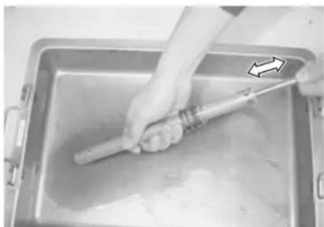
natural_image
Person using a tool to clean or wash material in a metal tray (no text or symbols visible)- Remove the dust seal.
- Remove the oil seal stopper ring.
- Pull the inner tube out of the outer tube.
NOTE:
Be careful not to damage the inner tube.
CAUTION
The slide metals, oil seal and dust seal must be replaced with the new ones when reassembling the front fork.
- Remove the following parts.
⑪ Oil seal
⑫ Oil seal retainer
⑬ Guide metal
⑭ Slide metal

natural_image
Close-up of a hand using a tool to adjust or install a mechanical component (no visible text or symbols)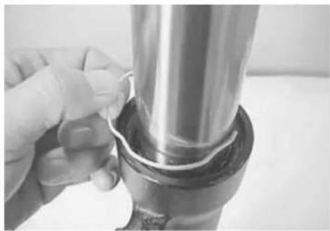
natural_image
Close-up of a hand adjusting a metallic cylindrical component with a black ring (no text or symbols visible)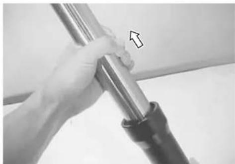
natural_image
Close-up of a hand holding a metallic cylindrical object with an arrow pointing to it (no text or symbols visible)
INSPECTION
INNER AND OUTER TUBES
Inspect the inner tube outer surface and the outer tube inner surface for scratches. If any defects are found, replace them with the new ones.

natural_image
Close-up of a hand holding a metallic cylindrical device with a reflective interior (no text or symbols visible)
natural_image
Close-up of a transparent cylindrical metal rod with a small black dot on its side (no text or symbols visible)FORK SPRING
Measure the fork spring free length. If it is shorter than the service limit, replace it with a new one.

Front fork spring free length
Service limit: 442.0 mm (17.40 in)

natural_image
Close-up of a coiled spring with measurement arrows (no text or symbols)DAMPER ROD
Move the inner rod by hand to examine it for smoothness. If any defects are found, replace the inner/damper rod (cartridge).

natural_image
Metal rod with two metal fasteners, no visible text or markingsREASSEMBLY AND REMOUNTING
Reassemble and remount the front fork in the reverse order of removal and disassembly. Pay attention to the following points:
TUBE METALS AND SEALS
- Hold the inner tube vertically and clean the metal groove and install the guide metal by hand as shown.
CAUTION
Use special care to prevent damage to the "Teflon" coated surface of the guide metal when mounting it.
- Apply fork oil to the oil seal lip lightly before installing it.
- Assemble the following parts as shown.
① Oil seal
② Oil seal retainer
③ Guide metal
④ Dust seal
⑤ Oil seal stopper ring
⑥ Slide metal
CAUTION
* When installing the oil seal to outer tube, be careful not to damage the oil seal lip.
* Do not use solvents for washing to prevent oil seal damage.
* Apply fork oil to the Anti-friction metals and lip of the oil seal.
* Make sure that the oil seal stopper ring ⑤ has been fitted securely.
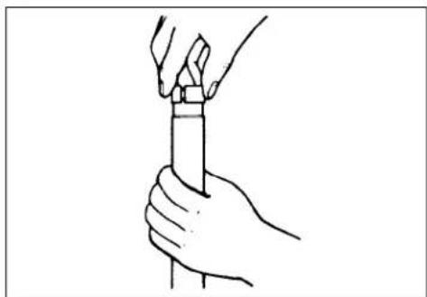
natural_image
Line drawing of a hand holding a pen or tool, no text or symbols present

- Insert the inner tube into the outer tube and fit the oil seal and dust seal with the special tool.

09940-52861: Front fork oil seal installer
NOTE:
Stamped mark on the oil seal should face outside.
DAMPER ROD BOLT
• Install the rebound spring and oil lock piece to the damper rod.
NOTE:
When installing the rebound spring, the smaller inner diameter of spring must seat the stopper of damper rod.
- Insert the inner rod/damper rod (cartridge) into the outer tube. - Apply THREAD LOCK "1342" to the damper rod bolt and tighten it to the specified torque.

99000-32050: THREAD LOCK "1342"

Damper rod bolt: 20 N·m (2.0 kgf·m, 14.5 lb·ft)
CAUTION
Use a new damper rod bolt gasket ⑦ to prevent oil leakage.
NOTE:
If the damper rod turns together with the damper rod bolt, temporarily install the fork spring, spacer, washer and cap bolt to prevent the damper rod from turning.
FORK OIL
- Place the front fork vertically without spring.
- Compress the front fork fully.
- Pour the specified front fork oil into the front fork up to the top of the inner rod.

99000-99001-SS8: SUZUKI FORK OIL SS-8


natural_image
Close-up of a metallic mechanical component with a coiled spring and cylindrical shaft (no text or symbols visible)
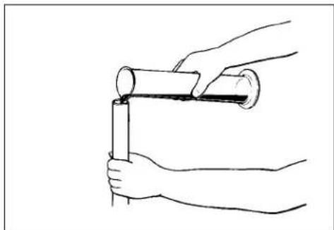
natural_image
Line drawing of hands holding a cylindrical object with a tube inserted (no text or symbols)- Move the inner rod slowly more than ten times until no more air bubbles come out from the oil.

09940-52841: Inner rod holder
NOTE:
Refill the front fork oil up to the top of the inner tube in order to find air bubbles while bleeding air.
- Move the inner tube up and down several strokes until no more bubbles come out from the oil.
- Keep the front fork vertically and leave it during 5 – 6 minutes.
NOTE:
* Always keep the oil level over the cartridge top end, or air may enter the cartridge during this procedure.
* Take extream attention to pump out air completely.
- Hold the front fork vertically and adjust the fork oil level with the special tool.
NOTE:
When adjusting the fork oil level, remove the fork spring and compress the inner tube fully.

09943-74111: Front fork oil level gauge

Fork oil level: 133.0 mm (5.24 in)
Capacity (each leg): 505.0 ml (17.07/17.78 US/lmp oz)

99000-99001-SS8: SUZUKI FORK OIL SS-8
FORK SPRING
- Pull the inner rod up with the inner rod holder.

09940-52841: Inner rod holder


natural_image
Hand holding a metallic cylindrical object with a vertical double-headed arrow indicating measurement (no text or symbols)
natural_image
Technical line drawing showing two mechanical setups: a vertical support device with a height dimension and a connected pipe with a handle (no text or symbols)
• Install the fork spring.
NOTE:
The smaller end of the fork spring should be at the bottom of the front fork.
FRONT FORK CAP BOLT
• Install the washer ① and spacer ②.
- Adjust the height ① of the inner rod threads by turning the lock nut ③ as shown.
Ⓐ: 10.5 mm (0.41 in)
- Tighten the front fork cap bolt to seat at lock nut by hand tightening.
- Hold the front fork cap bolt, tighten the lock nut to the specified torque.

Inner rod lock nut : 20 N·m (2.0 kgf·m, 14.5 lb·ft)
- Apply fork oil lightly to the O-ring.
CAUTION
Use a new O-ring to prevent oil leakage.
- Tighten the front fork cap bolt temporarily.

natural_image
Close-up of a metallic mechanical spring with a coiled spring and handle (no text or symbols visible)


natural_image
Close-up of a metallic mechanical component with a coiled spring and handle (no visible text or symbols)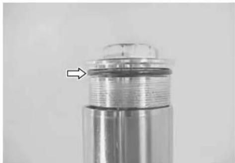
natural_image
Close-up of a metallic cylindrical object with a lid and threaded base, marked by an arrow (no text or symbols visible)- Set the front fork to the front fork lower bracket temporarily by tightening the lower clamp bolts.
- Tighten the front fork cap bolt ④ to the specified torque.
Front fork cap bolt: 23 N·m (2.3 kgf-m, 16.5 lb-ft)
- Align the top of the inner tube to the upper surface of the steering stem upper bracket.
- Tighten the front fork upper and lower clamp bolts.
Front fork upper clamp bolt: 23 N·m (2.3 kgf-m, 16.5 lb-ft) Front fork lower clamp bolt: 23 N·m (2.3 kgf-m, 16.5 lb-ft)
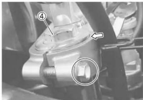
natural_image
Close-up of mechanical components with numbered annotations (4 and 5) and a highlighted section, no readable text or symbols present.
natural_image
Close-up of a mechanical component with a magnified inset showing a small circular feature (no visible text or symbols)• Install the front wheel. (6-13)
• Install the front brake calipers.(6-13)
NOTE:
After install the brake calipers, front brake should be efficient by pumping the front brake lever.
STEERING AND HANDLEBAR CONSTRUCTION
① Handlebars
② Steering stem upper bracket
③ Dust seal
④ Bearing upper
⑤ Bearing lower
⑥ Steering stem lower bracket
⑦ Dust cover
⑧ Steering stem nut
⑨ Handlebar balancer
⑩ Expander
⑪ Spacer
⑫ Washer
⑬ Expander
Ⓐ Handlebar clamp bolt
⑧ Steering stem head nut
© Handlebar holder nut
(D) Front fork upper clamp bolt
E Steering stem lock nut
⑤ Front fork lower clamp bolt

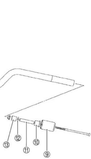
U
| ITEM N·m kgf·m lb·ft | |||
| A | 23 2.3 | 16.5 | |
| B | 90 9.0 | 65.0 | |
| C | 45 4.5 | 3245 | |
| D | 23 2.3 | 16.5 | |
| E | 80 8.0 | 58.0 | |
| F | 23 2.3 | 16.5 | 1 |
REMOVAL HANDLEBARS
- Remove the handlebar balancer ①.
- Remove the brake/clutch lever covers ②.
NOTE:
Do not remove the handlebar balancer mounting screw before removing the handlebar balancer. Slightly loosen the mounting screw, and then pull the balancer assembly out of handlebars.
- Remove the rear view mirror ③.
- Disconnect the front brake light switch coupler ④.
- Remove the front brake master cylinder.
- Remove the right handlebar switch box ⑤ and throttle case ⑥.
- Disconnect the clutch switch lead wires ⑦.
- Remove the left handlebar switch box ⑧.
- Remove the rear view mirror ⑨.
- Remove the clutch master cylinder.
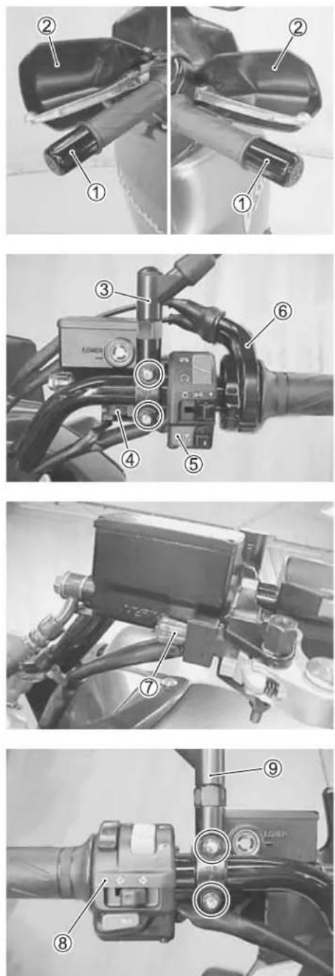
- Remove the handlebars by removing the handlebar clamp bolts.
STEERING STEM
- Remove the front forks and front fender. (6-15)
- Remove the handlebars. (6-25)
- Remove the brake hose guide ①.
- Remove the brake hose guide ②.
- Remove the ignition switch ③ by using the special tools.

09930-11920: Torx bit JT40H
09930-11940: Bit holder
- Remove the steering stem upper bracket by removing the steering stem nut.

natural_image
Close-up of mechanical components with circular annotations highlighting specific parts (no readable text or symbols)
natural_image
Close-up of a mechanical component with labeled parts (1 and 2), no readable text or symbols beyond labels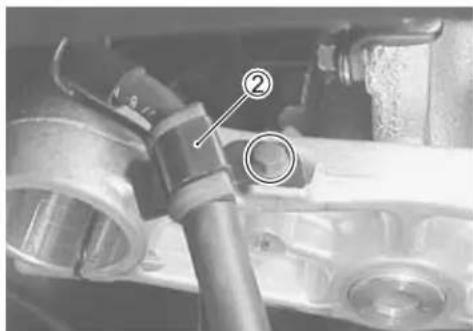
natural_image
Close-up of mechanical components with numbered annotations (② and ②) indicating specific parts, no readable text or symbols present.
natural_image
Close-up of a mechanical component with no visible text or symbols
natural_image
Close-up of mechanical components including a bracket and mounting bracket (no visible text or symbols)- Remove the handle holder nuts ④ and disassemble the handle holder.
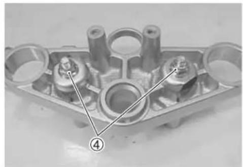
natural_image
Mechanical component with numbered annotation (4) showing internal cavities and shafts (no readable text or symbols)
natural_image
Disassembled mechanical component with bolts and connectors (no text or symbols visible)- Remove the steering stem nuts with the special tools.

09940-14911: Steering stem nut wrench 9940-14960: Steering stem nut wrench
NOTE:
When loosing the stem nuts, hold the steering stem lower bracket to prevent it from falling.
- Remove the steering stem lower bracket.
- Remove the dust cover ⑤, the dust seal ⑥.
- Remove the steering stem upper bearing ⑦.
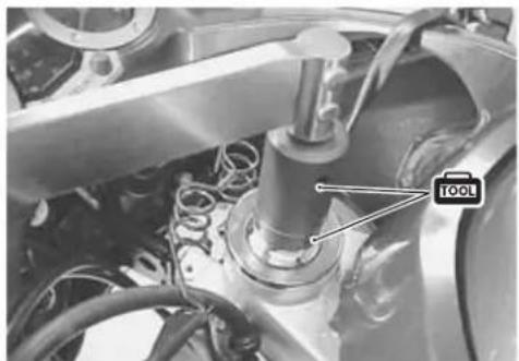
natural_image
Close-up of a mechanical assembly with a tool labeled 'TOOL' pointing to a component (no readable text or symbols beyond the label)
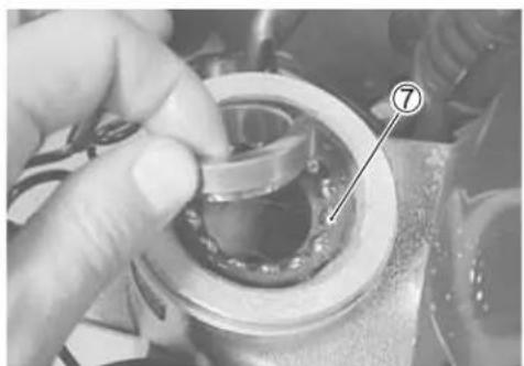
natural_image
Close-up of a hand adjusting a ball bearing component, labeled with number 7 (no text or symbols on the object itself)- Remove the steering stem lower bearing ⑧.
INSPECTION AND DISASSEMBLY
Inspect the removed parts for the following abnormalities.
* Handlebars distiction
* Race wear and brinelling
* Bearing wear or damage
* Abnormal bearing noise
* Distortion of the steering stem
If any abnormal points are found, replace defective parts with the new ones.
- Remove the steering stem lower bearing inner race using a chisel.
CAUTION
The removed bearing inner race and dust seal must be replaced with the new ones.
- Drive out the steering stem upper and lower bearing races using the special tools.

09941-54911: Bearing outer race remover
09925-18011: Steering bearing installer

natural_image
Close-up of a hand adjusting a ball bearing with an arrow pointing to the bolt (no text or symbols visible)
natural_image
Metal T-shaped tool component on a plain surface (no text or symbols visible)
natural_image
Line drawing of a hand using a tool to lift a mechanical component (no text or symbols)
natural_image
Technical line drawings showing a mechanical device with a tool and a hand holding a hammer (no text or symbols present)REASSEMBLY AND REMOUNTING
Reassemble and remount the steering stem in the reverse order of removal and disassembly. Pay attention to the following points:
OUTER RACES
- Press in the upper and lower outer races using the special tool.

09941-34513: Steering outer race installer 09913-70210: Bearing installer set
BEARINGS
- Press in the dust seal and lower bearing using the special tool.

09925-18011: Steering bearing installer
- Apply grease to the bearings and dust seal.
• Install the lower bearing to the steering stem lower bracket.
• Install the upper bearing, bearing inner race, dust seal and dust cover onto the frame.

99000-25030: SUZUKI SUPER GREASE "A" (USA) 99000-25010: SUZUKI SUPER GREASE "A" (Others)
STEERING STEM
- Tighten the steering stem nut to the specified torque with the special tools.

09940-14911: Steering stem nut wrench 09940-14960: Steering stem nut wrench socket

Steering stem nut: 45 N·m (4.5 kgf-m, 32.5 lb-ft)
- Turn the steering stem about five or six times to the left and right so that the angular ball bearing will be seated properly.
- Loosen the steering stem nut by 14 - 12 turn.
NOTE:
This adjustment will vary from motorcycle to motorcycle.

natural_image
Technical illustration showing a bolt and a tool interacting with a mechanical component (no text or symbols)

natural_image
Close-up of two metal ball bearings with labeled section A, shown from a hand holding the ring (no text or symbols on the bearings themselves)

natural_image
Two-step diagram showing a mechanical component before and after turning a circular component, with no text or symbols present.• Install the washer.
NOTE:
When installing the washer, align the stopper lug to the groove of the steering stem.
• Install the steering stem lock nut and tighten it to the specified torque with the special tools.

09940-14911: Steering stem nut wrench
09940-14960: Steering stem nut wrench socket

Steering stem lock nut: 80 N·m (8.0 kgf-m, 58.0 lb-ft)
- Reassemble the handlebar holders to the steering stem upper bracket. - Tighten the handlebar holder nuts to the specified torque.

Handlebar holder nut: 45 N·m (4.5 kgf·m, 32.5 lb·ft)
NOTE:
Before tightening the nut to the specified torque, temporarily install the handlebars in order to align both holders.
• Install the steering stem upper bracket and tighten the steering stem nut lightly.
• Install the ignition switch ① and harness guide ②. (7-31)
• Install the front fork to the steering stem and tighten the lower clamp bolts temporarily.
- Tighten the steering stem head nut to the specified toupue.

Steering stem head nut: 90 N·m (9.0 kgf·m, 65.0 lb·ft)
- Remount the front forks and the front fender. (6-23)
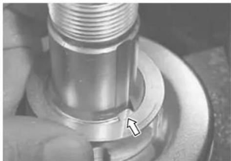
natural_image
Close-up of a mechanical component with threaded shaft and flange, showing a small white arrow pointing to a feature (no text or symbols visible)
natural_image
Close-up of a mechanical assembly with visible tool and wiring (no text or symbols)
natural_image
Close-up of a mechanical clamp or bracket assembly with metal components and a wooden base (no visible text or symbols)

natural_image
Close-up of mechanical components with metallic fittings and bolts (no visible text or symbols)HANDLEBARS
• Install the handlebars with the punch mark Ⓐ aligned with the mating surface Ⓑ of the handlebar holder.
- Set the punch mark © on the handlebar clamp forward.
- Tighten the handlebar clamp bolts to the specified torque.
Handlebar clamp bolt: 23 N·m (2.3 kgf·m, 16.5 lb·ft)
NOTE:
When tightening the handlebar clamp bolts, first tighten the bolt ① and then tighten the bolt ②.
HANDLEBAR SWITCH BOX
• Install the throttle cable case.
- Apply grease to the throttle cables and their holes.

99000-25030: SUZUKI SUPER GREASE "A" (USA) 99000-25010: SUZUKI SUPER GREASE "A" (Others)
- Align the mating surface Ⓑ of the throttle case with the punch mark Ⓐ on the handlebars.
- Install the right handlebar switch box to the handlebars by engaging the stopper ① with the handlebar's hole ②.
• Install the front brake master cylinder. (6-65)

natural_image
Close-up of cylindrical batteries with labeled points A and B, no visible text or symbols on the main subject.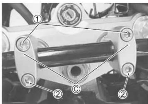

natural_image
Close-up of a hand holding a bicycle brake lever with visible wiring and a labeled component (no text or symbols)

• Install the left handlebar switch box to the handlebars by engaging the stopper ① with the handlebars hole ②.
• Install the clutch master cylinder with the proper clutch hose routing.
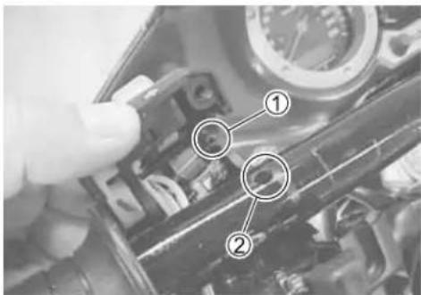
• Install the handlebar balancers and the rear view mirrors.
(Handlbar balancer installation: 8-31)
• Install the front wheel. (6-13)
STEERING TENSION ADJUSTMENT
Check the steering movement in the following procedure.
- By supporting the motorcycle with a jack, lift the front wheel until it is off the floor by 20 – 30 mm (0.8 – 1.2 in).
- Check to make sure that the cables and wire harnesses are properly routed.
- With the front wheel in the straight ahead state, hitch the spring scale (special tool) on one handlebar grip end as shown in the figure and read the graduation when the handlebar starts moving. Do the same on the other grip end.
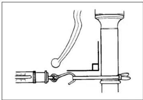
natural_image
Technical line drawing of a mechanical device with no visible text or symbolsDATA
Initial force: 200 - 500 grams
TOOL
09940-92720: Spring scale
- If the initial force read on the scale when the handlebar starts turning is either too heavy or too light, adjust it till it satisfies the specification.
1) First, loosen the front fork upper and lower clamp bolts, steering stem head nut and steering stem lock nut, and then adjust the steering stem nut by loosening or tightening it.
2) Tighten the steering stem lock nut, stem head nut and front fork upper and lower clamp bolts to the specified torque and re-check the initial force with the spring scale according to the previously described procedure.
3) If the initial force is found within the specified range, adjustment has been completed.
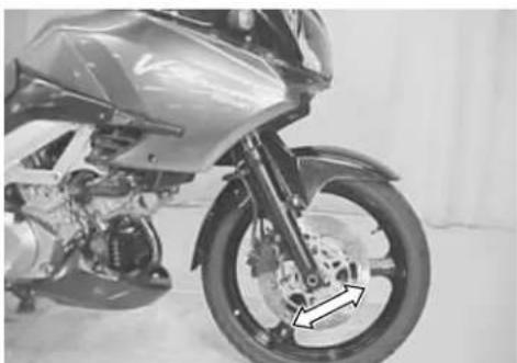
natural_image
Close-up of a motorcycle wheel and brake disc with visible mechanical components (no text or symbols)NOTE:
Hold the front fork legs, move them back and forth and make sure that the steering is not loose.
REAR WHEEL CONSTRUCTION

① Rear axle
② Dust seal
③ Brake disc
④ Collar
⑤ Bearing
⑥ Rear wheel
⑦ Tire valve
⑧ Damper
⑨ Spacer
⑩ Bearing
⑪ Retainer
⑫ Sprocket mounting drum
⑬ Rear sprocket
⑭ Bearing
⑮ Dust seal
⑯ Collar
Ⓐ Brake disc bolt
⑧ Rear sprocket nut
© Rear axle nut
U
| ITEM N·m kgf·m lb·ft | |||
| A | 23 2.3 | 16.5 | |
| B | 60 6.0 | 43.5 | |
| C | 100 10.0 | 72.5 | |
REMOVAL
- Remove the cotter pin. (For E-03, 28, 33)
- Loosen the rear axle nut ①.
- Raise the rear wheel off the ground and support the motorcycle with a jack or wooden block.
- Remove the axle nut and draw out the rear axle.
CAUTION
Do not operate the brake pedal while removing the rear wheel.
- Remove the collars ②, ③.
- Remove the rear sprocket mounting drum assembly ④ from the wheel hub.
NOTE:
Before removing the rear sprocket mounting drum, slightly loosen the rear sprocket nuts to facilitate later disassembly.
- Remove the rear sprocket mounting drum retainer ⑤.
- Remove the rear sprocket from sprocket mounting drum.

natural_image
Close-up of a mechanical brake assembly with labeled component (1), no visible text or symbols beyond the number marker.
natural_image
Close-up of mechanical components showing a gear and housing with numbered annotations (no readable text or symbols)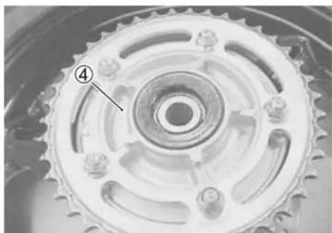
natural_image
Close-up of a mechanical gear assembly with teeth and central hub (no text or symbols visible)
natural_image
Close-up of a hand holding a metallic mechanical component, with inset view showing internal components (no text or symbols visible)- Remove the brake disc.

natural_image
Close-up of a car brake disc with four circular mounting holes (no text or symbols visible)INSPECTION AND DISASSEMBLY
TIRE: (6-84)
WHEEL: (6-10 and 6-84)
REAR AXLE
Using a dial gauge, check the rear axle for runout.
If the runout exceeds the limit, replace the rear axle.

Axle shaft runout: Service Limit: 0.25 mm (0.010 in)

09900-20607: Dial gauge (1/100 mm)
09900-20701: Magnetic stand
09900-21304: V-block set (100 mm)

natural_image
Technical line drawing of a mechanical device with pressure gauge and lever (no text or symbols)WHEEL DAMPER
Inspect the dampers for wear and damage.
Replace the damper if there is anything unusual.

natural_image
Two metallic mechanical components with rounded ends and mounting holes, displayed against a plain background (no text or symbols visible)SPROCKET
Inspect the rear sprocket teeth for wear. If they are worn as shown, replace the engine sprocket, rear sprocket and drive chain as a set.
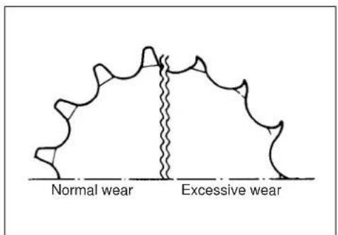
DUST SEAL
- Inspect the wheel dust seal lip and sprocket mounting drum dust seal lips for wear or damage. If any damages are found, replace the dust seal with a new one.

natural_image
Close-up of a mechanical component with a central bore and an arrow pointing to a hole (no text or symbols visible)
natural_image
Close-up of a mechanical component with concentric rings and a white arrow pointing to a specific feature (no text or symbols visible)- Remove the dust seal with the special tool.

09913-50121: Oil seal remover
CAUTION
Do not reuse the removed dust seal.

natural_image
Mechanical assembly with a tool labeled 'TOOL' pointing to a central component (no other text or symbols visible)
natural_image
Close-up of a car brake caliper with a tool labeled 'TOOL' pointing to the wheel (no other text or symbols visible)BEARING
Inspect the play of the wheel and sprocket mounting drum bearings by hand while they are in the wheel and drum. Rotate the inner race by hand to inspect for abnormal noise and smooth rotation. Replace the bearing if there is anything unusual.
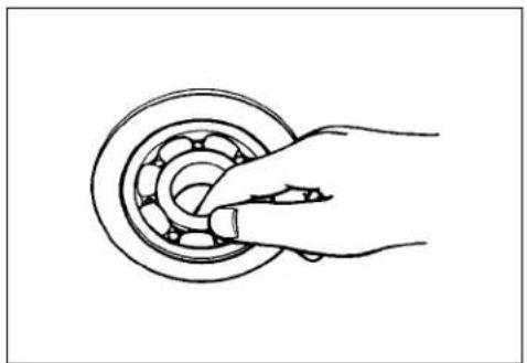
natural_image
Line drawing of a hand pressing down on a ball bearing (no text or symbols)- Remove the sprocket mounting drum bearing and wheel bearings by using the special tool.

09921-20240: Bearing remover set
CAUTION
The removed bearings must be replaced with the new ones.

natural_image
Close-up of a mechanical assembly with a hand adjusting a tool, no visible text or symbols on the main subject.
natural_image
Close-up of a car tire assembly with a tool inserted, showing mechanical components and no visible text or symbols.REASSEMBLY AND REMOUNTING
Reassemble and remount the rear wheel in the reverse order of removal and disassembly. Pay attention to the following points:

BEARING
- Apply grease to the bearings before installing.

99000-25030: SUZUKI SUPER GREASE "A" (USA) 99000-25010: SUZUKI SUPER GREASE "A" (Others)
• Install the new bearing to the sprocket mounting drum using the special tool.

09924-84510: Bearing installer set
NOTE:
When installing the bearing, non-sealed side of bearing must face the special tool.
- First install the right wheel bearing, then install the left wheel bearing and spacer using the special tool.

09941-34513: Bearing/Steering race installer set
CAUTION
The sealed cover of the bearing must face outside.

natural_image
Line drawing of hands holding a cylindrical object with a lid, no text or symbols present
natural_image
Close-up of a hand using a compass to adjust or install a mechanical component (no visible text or symbols)

DUST SEAL
• Install the new dust seal using the special tool.

09913-70210: Bearing installer set
- Apply SUZUKI SUPER GREASE "A" to the dust seal lips before assembling rear wheel.

99000-25030: SUZUKI SUPER GREASE "A" (USA)
99000-25010: SUZUKI SUPER GREASE "A" (Others)
NOTE:
When installing the dust seals, the stamped mark of dust seal must face the special tool.

natural_image
Close-up of a mechanical component with a cylindrical shaft and mounting flange, labeled 'TOOL' with an arrow pointing to it (no other text or symbols visible)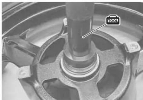
natural_image
Close-up of a mechanical component with a labeled 'TOOL' icon, showing internal structure without any readable text or symbols.BRAKE DISC
Make sure that the brake disc is clean and free of any greasy matter.
- Apply THREAD LOCK SUPER "1360" to the disc bolts and tighten them to the specified torque.

natural_image
Close-up of a car brake disc with four circular mounting holes (no text or symbols visible)
99000-32130: THREAD LOCK SUPER "1360"

Brake disc bolt: 23 N·m (2.3 kgf-m, 16.5 lb-ft)
REAR SPROCKET
- Tighten the sprocket mounting nuts to the specified torque.

Rear sprocket nut: 60 N·m (6.0 kgf-m, 43.5 lb-ft)
NOTE:
Stamped mark Ⓐ on the sprocket must face outside.

natural_image
Close-up of a mechanical gear assembly with labeled points A and B (no text or symbols beyond labels)- Apply SUZUKI SUPER GREASE "A" to the rear sprocket mounting retainer.
• Install the rear sprocket mounting drum retainer. - Apply SUZUKI SUPER GREASE "A" to the contacting surface between the rear wheel and the sprocket drum.

natural_image
Close-up of mechanical components with no visible text or symbols
99000-25030: SUZUKI SUPER GREASE "A" (USA)
99000-25010: SUZUKI SUPER GREASE "A" (Others)
• Install the rear sprocket mounting drum to the rear wheel.
• Install the collar.
REAR AXLE
- Remount the rear wheel and rear axle, install the washer and rear axle nut.
- Tighten the rear axle nut ① to the specified torque.
- Adjust the chain slack after rear wheel installation. (2-19)

Rear axle nut: 100 N·m (10.0 kgf·m, 72.5 lb·ft)
• Install the new cotter pin. (For E-03, 28, 33)

natural_image
Close-up of a mechanical component with concentric rings and bolted flanges (no visible text or symbols)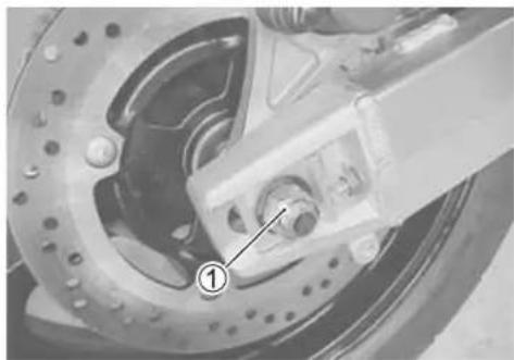
natural_image
Close-up of a car brake system with labeled component (①), no visible text or symbols beyond the number marker.REAR SHOCK ABSORBER CONSTRUCTION

① Rear shock absorber
Ⓐ Rear shock absorber upper mounting nut
⑧ Rear shock absorber lower mounting nut
[NO TEXT]
| ITEM N·m kgf-m lb-ft | |||
| A | 50 5.0 | 36.0 | |
| B | 50 5.0 | 36.0 | |
REMOVAL
- Raise the rear wheel off the ground and support the motorcycle with a jack or wooden block.
- Remove the pre-load adjuster ①.
- Remove the cushion lever rod bolts/nuts and the cushion rods ②.
- Remove the rear shock absorber upper mounting bolt.
- Remove the rear shock absorber lower mounting bolt.
- Remove the rear shock absorber ③.

natural_image
Mechanical assembly diagram showing a gear-like component with two circular annotations pointing to specific parts (no readable text or symbols)
natural_image
Close-up of mechanical components with numbered annotations (2 and 3) and circular features, no readable text or symbols.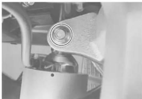
natural_image
Close-up of a mechanical component with a circular head and lever mechanism (no visible text or symbols)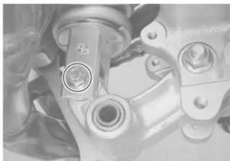
natural_image
Close-up of mechanical components with no visible text or symbols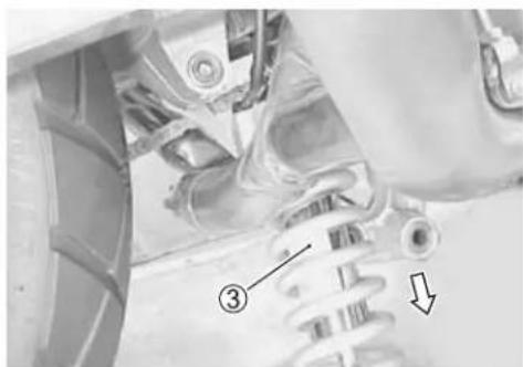
natural_image
Mechanical assembly diagram showing a spring and housing component with numbered annotation (no readable text or symbols)INSPECTION
Inspect the shock absorber body and bushing for damage and oil leakage.
If any defects are found, replace the shock absorber with a new one.
CAUTION
Do not attempt to disassemble the rear shock absorber unit. It is unserviceable.
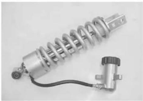
natural_image
Two mechanical components: a metallic spring and a pressure regulator with coiled tubing (no visible text or symbols)REAR SHOCK ABSORBER DISPOSAL
WARNING
The rear shock unit contains high-pressure nitrogen gas. Mishandling can cause explosion.
* Keep away from fire and heat. High gas pressure caused by heat can cause an explosion.
* Release gas pressure before disposing.
GAS PRESSURE RELEASE
- Mark the drill hole at Ⓐ, shown in the illustration, with a center punch.

• Cover the rear shock absorber with a transparent vinyl bag ①.
- Hold the rear shock absorber ② with a vice.
• Make a hole with a 3 mm drill.
WARNING
Wear eye protection to protect your eyes from released gas and metal chips.

REMOUNTING
Remount the rear shock absorbers in the reverse order of removal. Pay attention to the following points:
• Install the rear shock absorber and tighten the rear shock absorber upper/lower mounting nuts.

Rear shock absorber mounting lower nut:
50 N·m (5.0 kgf-m, 36.0 lb-ft)
Rear shock absober mounting upper nut:
50 N·m (5.0 kgf-m, 36.0 lb-ft)
NOTE:
When installing the rear shock absorber, the outlet hose of the prel-load adjuster faces backward.
- Clamp the pre-load adjuster hose ①.
• Install the cushion rod ②.
- Tighten the cushion rod nuts to the specified torque.

Cushion rod nut: 78 N·m (7.8 kgf-m, 56.5 lb-ft)

natural_image
Close-up of a mechanical component with a circular component and textured surface (no visible text or symbols)
natural_image
Close-up of mechanical components with no visible text or symbols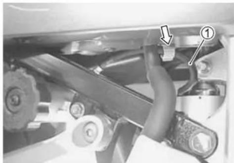
natural_image
Mechanical assembly diagram showing a lever mechanism with labeled component (①), no readable text or symbols present.
natural_image
Close-up of mechanical components with numbered annotations (② and circled) indicating specific parts, no readable text or symbols present.SUSPENSION SETTING
After installing the rear suspension, adjust the spring pre-load and damping force as follows.
SPRING PRE-LOAD ADJUSTMENT
The pre-load is adjusted by turning the pre-load adjuster knob without tool.
Position "0" provides the softest spring pre-load.
Position "5" provides the stiffest spring pre-load.
STD position: "2"
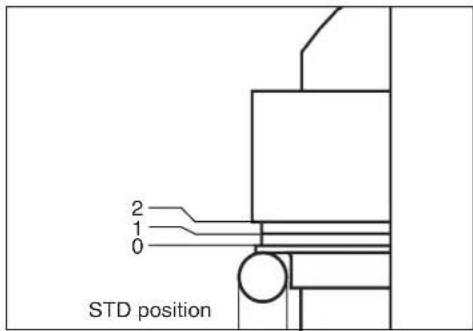
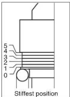
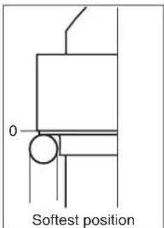
DAMPING FORCE ADJUSTMENT
The rebound damping force is adjusted by turning the adjuster. Fully turn the damping adjuster ① clockwise. It is at stiffest position and turn it out to standard setting position.
STD position: 78 turn out from stiffest position
CAUTION
Do not turn the adjuster more than the given position or the adjuster may be damaged.

REAR SWINGARM CONSTRUCTION

① Rear shock absorber
② Rear cushion rod
③ Rear cushion lever
④ Spacer
⑤ Bearing
⑥ Washer
⑦ Pivot spacer
⑧ Chain cover
⑨ Chain buffer
⑩ Swlngarm
⑪ Center spacer
Ⓐ Rear shock absorber upper mounting nut
⑧ Rear cusion lever nut
© Rear cusion rod nut
D Swingarm pivot shaft
E Swingarm pivot lock nut
⑤ Swingarm pivot nut
© Rear shock absorber lower mounting nut

U
| ITEM N-m kgf-m lb-ft | |||
| A | 50 5.0 | 36.0 | |
| B | 78 7.8 | 56.5 | |
| C | 78 7.8 | 56.5 | |
| D | 15 1.5 | 11.0 | |
| E | 90 9.0 | 65.0 | |
| F | 100 10.0 | 72.5 | |
| G | 50 5.0 | 36.0 | 6 |
REMOVAL
- Remove the exhaust pipe and exhaust muffler. (3-7)
- Raise the rear wheel off the ground and support the motorcycle with a jack or wooden block.
- Remove the rear wheel. (6-34)
-
Remove the rear brake hose guide ①.
-
Remove the cushion rods ②.
- Remove the shock absorber ③.
- Remove the cushion lever ④.
- Remove the swingarm pivot shaft lock nut by using the special tool.

09940-14940: Swingarm pivot thrust adjuster socket wrench
- Hold the swingarm pivot shaft ⑤ and remove the swingarm pivot nut ⑥.
- Remove the swingarm pivot shaft by using the special tool.

09944-28320: Hexagon bit 19 mm
- Remove the chain cover.


natural_image
Close-up of a mechanical assembly with a tool inserted, showing no visible text or symbols.

natural_image
Close-up of a mechanical component with two circular features, no visible text or symbols- Remove the mud guard ⑦.
- Remove the brake hose guide ⑧.
- Remove the chain buffer ⑨.


natural_image
Mechanical component with numbered callouts highlighting features (no readable text or symbols)INSPECTION AND DISASSEMBLY
SPACER
- Remove the spacers from swingarm and cushion lever.
- Inspect the spacers for any flaws or other damage. If any defects are found, replace the spacers with the new ones.

natural_image
Close-up of a hand holding a metallic cylindrical mechanical component with a flange, no visible text or symbols.
natural_image
Metal mechanical component with three ports and a Y-shaped groove (no text or symbols visible)
natural_image
Close-up of a hand turning a small mechanical component (no visible text or symbols)CHAIN BUFFER
Inspect the chain buffer for damage and excessive wear. If any defects are found, replace the chain buffer with a new one.
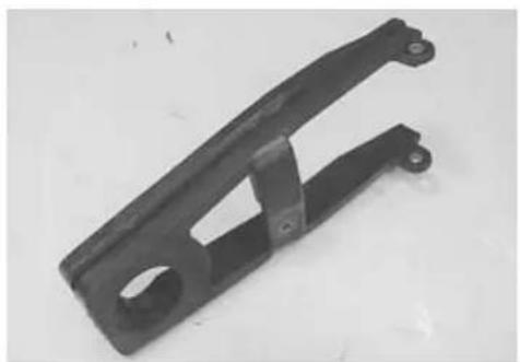
natural_image
Metal bracket component with mounting holes and a central hole (no text or symbols visible)SWINGARM BEARING
Insert the spacer into bearing and check the play when moving the spacer up and down.
If excessive play is noted, replace the bearing with a new one.

natural_image
Close-up of a hand holding a small mechanical component, possibly a valve or knob, against a plain background (no text or symbols visible)
natural_image
Close-up of a hand turning a button on a mechanical component (no visible text or symbols)- Remove the swingarm pivot bearing and spacer with the special tools.

09923-74511: Bearing remover 9930-30102: Sliding shaft
CAUTION
Do not reuse the removed bearings.

- Remove the cushion rod bearings by using the special tool.

09913-73210: Bearing remover 9930-30102: Sliding shaft

CAUTION
Do not reuse the removed bearings.
SWINGARM PIVOT SHAFT
Using a dial gauge, check the pivot shaft runout and replace it if the runout exceeds the limit.

09900-20607: Dial gauge (1/100 mm, 10 mm) 9900-20701: Magnetic stand 9900-21304: V-block (100 mm)

Swingarm pivot shaft runout: Service limit: 0.3 mm (0.01 in)
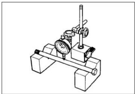
natural_image
Technical line drawing of a mechanical testing apparatus with pressure gauge and lever (no text or symbols)CUSHION LEVER BEARING
Insert the spacer into bearing and check the play when moving the spacer up and down.
If excessive play is noted, replace the bearing with a new one.
- Draw out the cushion lever bearings with the special tool.

09921-20240: Bearing remover set
CAUTION
The removed bearings must be replaced with new ones.
CUSHION LEVER RODS
Inspect the cushion lever rods for damage and distortion.

natural_image
Metal mechanical component with three ports and four directional arrows indicating flow or movement (no text or symbols)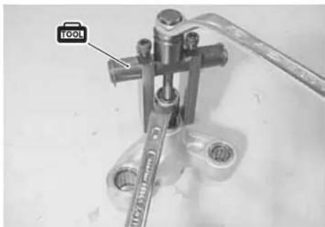

natural_image
Two metallic mechanical linkages with circular holes, one labeled '0.80' (no other text or symbols visible)REASSEMBLY
Reassemble the swingarm in the reverse order of disassembly and removal.
Pay attention to the following points:

SWINGARM BEARING
• Install the bearings and spacer into the swingarm pivot all together by using the special tool.

09941-34513: Steering race installer
NOTE:
When installing the bearing, the stamped mark on the bearing must face the special tool.
• Install the cushion rod bearing with the special tool.

09941-34513: Steering race installer
NOTE:
When installing the bearing, the dust seal that is embedded in the bearing must face outside.
CUSHION LEVER BEARING
- Press the bearings into the cushion lever with the special tool.

09941-34513: Steering race installer
NOTE:
When installing the bearing, the dust seal that is embedded in the bearing must face outside.
- Apply grease to the bearings and spacers.

99000-25030: SUZUKI SUPER GREASE "A" (USA) 9000-25010: SUZUKI SUPER GREASE "A" (Others)
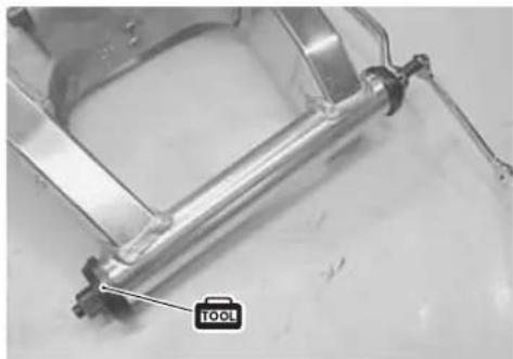
natural_image
Close-up of a metallic mechanical component with a labeled tool (no readable text or symbols)

natural_image
Mechanical component with a labeled tool (no text or symbols on the object itself)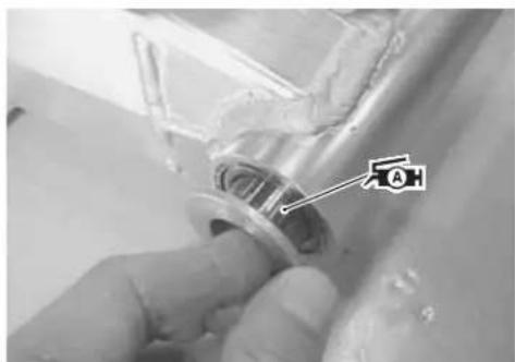

natural_image
Close-up of a mechanical component with a labeled section (A) and arrow pointing to a cylindrical feature (no readable text or symbols)
REMOUNTING
Remount the swingarm in the reverse order of disassembly and removal, and pay attention to the following points:
SWINGARM
- Insert the swingarm pivot shaft and tighten it to the specified torque by using the special tool.

Swingarm pivot shaft: 15 N·m (1.5 kgf·m, 11.0 lb·ft)

09944-28320: Hexagon bit 19 mm
- Hold the swingarm pivot shaft ① and tighten the swingarm pivot nut ② to the specified torque.

Swingarm pivot nut: 100 N·m (10.0 kgf-m, 72.5 lb-ft)
- Tighten the swingarm pivot lock nut to the specified torque with the special tool.

09940-14940: Swingarm pivot thrust adjuster socket wrench

Swingarm pivot lock nut: 90 N·m (9.0 kgf-m, 65.0 lb-ft)

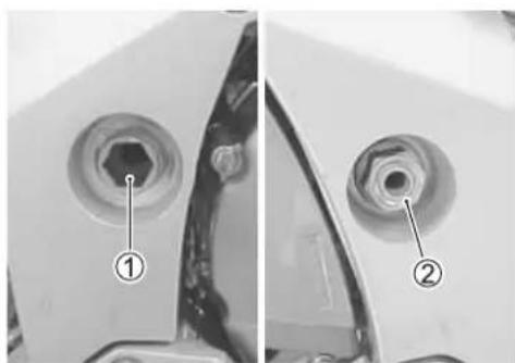
natural_image
Close-up of mechanical components with numbered callouts (① and ②), no visible text or symbols beyond labels
CUSHION LEVER AND CUSHION ROD
• Install the washers ① and cushion lever.
NOTE:
Insert the cushion lever mounting bolt from the left side.
(6-52)
• Install the cushion rod and rear shock absorber.
NOTE:
Insert the cushion rod mounting bolts and rear shock absorber mounting bolts from the left side. (6-52)
- Tighten the cushion lever nut ②, cushion rod nut ③ and rear shock absorber nut to the specified torque.

Cushion lever mounting nut:
78 N·m (7.8 kgf-m, 56.5 lb-ft)
Cushion rod nut: 78 N·m (7.8 kgf-m, 56.5 lb-ft)
Rear shock absorber mounting nut:
50 N·m (5.0 kgf-m, 36.0 lb-ft)
• Install the rear brake hose guide.
• Install the rear wheel. (6-41)
• Install the exhaust pipe and muffler. (3-15)

natural_image
Close-up of a hand adjusting a mechanical component with a numbered annotation (1) and tool, no readable text or symbols present.
FINAL INSPECTION AND ADJUSTMENT
After installing the rear suspension and wheel, the following adjustments are required before driving.
* Drive chain: 2-19
* Tire pressure: 6-86
* Chassis bolts and nuts: 2-27
① Diaphragm
② Dust boot
③ Piston/cup set
④ Brake hose
⑤ Pin
⑥ Pad mounting pin
⑦ Brake pad spring
⑧ Brake pad
⑨ Piston seal
⑩ Dust seal
⑪ Piston
⑫ Caliper holder
⑬ Caliper
Ⓐ Front brake master cylinder mounting bolt
⑧ Brake hose union bolt
© Air bleeder valve
⑭ Brake caliper mounting bolt

| ITEM | N-m | kgf-m | lb-ft | |
| A | 10 | 1.0 | 7.0 | |
| B | 23 | 2.3 | 16.5 | |
| C | 7.5 | 0.75 | 5.5 | |
| D | 39 | 3.9 | 28.0 |
WARNING
* This brake system is filled with an ethylene glycol-based DOT 4 brake fluid. Do not use mix different types of fluid such as silicone-based or petroleum-based.
* Do not use any brake fluid taken from old, used or unsealed containers. Never reuse brake fluid left over from the last servicing or stored for long periods.
* When storing the brake fluid, seal the container completely and keep away from children.
* When replenishing brake fluid, take care not to get dust into fluid.
* When washing brake components, use fresh brake fluid. Never use cleaning solvent.
* A contaminated brake disc or brake pad reduces braking performance. Discard contaminated pads and clean the disc with high quality brake cleaner or neutral detergent.
CAUTION
Handle brake fluid with care: the fluid reacts chemically with paint, plastics, rubber materials etc. and will damage then severely.
BRAKE PAD REPLACEMENT
- Remove the caliper.
CAUTION
Do not operate the brake lever while removing the caliper.
- Remove the pin ①.
- Remove the brake pads by removing the pad mounting pin ②.
- Clean up the caliper especially around the caliper pistons.
- Install the outer pad with the detent Ⓐ of pad fitted to the detent Ⓑ on the caliper holder.
CAUTION
Replace the brake pads as a set, otherwise braking performance will be adversely affected.
- Install the inner pad so that the inner pad will be seated on the hatched part ©.
• Install the pad mounting pin ③.
- Install the pin ④ securely.

natural_image
Close-up of a motorcycle brake caliper assembly with two circular fasteners (no visible text or symbols)


natural_image
Close-up of mechanical components with no visible text or symbols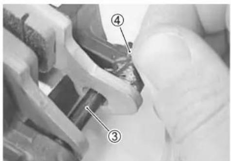
- Remount the caliper.
- Tighten the caliper mounting bolts to the specified torque.

Front brake caliper mounting bolt:
39 N·m (3.9 kgf-m, 28.0 lb-ft)
NOTE:
After replacing the brake pads, pump the brake lever several times to check for proper brake operation and then check the brake fluid level.
BRAKE FLUID REPLACEMENT
- Place the motorcycle on a level surface and keep the handlebars straight.
- Remove the brake fluid reservoir cap and diaphragm.
- Suck up the old brake fluid as much as possible.
- Fill the reservoir with the new brake fluid.

Specification and Classification: DOT 4
- Connect a clear hose to the caliper air bleeder valve and insert the other end of hose into a receptacle.
- Loosen the air bleeder valve and pump the brake lever until old brake fluid flows out of the bleeder system.
- Close the caliper air bleeder valve and disconnect a clear hose. Fill the reservoir with the new fluid to the upper mark of the reservoir.

Brake air bleeder valve: 7.5 N·m (0.75 kgf-m, 5.5 lb-ft)
CAUTION
* Never reuse the brake fluid left over from previous servicing and which has been stored for long periods of time.
* Bleed air from the brake system.
(2-24)

natural_image
Close-up of a motorcycle brake caliper assembly with mounting holes (no visible text or symbols)
natural_image
Close-up of mechanical components including a bulb, valve, and motor assembly (no visible text or symbols)
natural_image
Close-up of a hand adjusting a brake caliper on a vehicle wheel (no visible text or symbols)
natural_image
Close-up of a mechanical device with a lever and fluid bag, showing motion direction (no text or symbols visible)CALIPER REMOVAL AND DISASSEMBLY
- Drain the brake fluid. (6-58)
- Remove the brake pads. (6-57)
- Disconnect the brake hoses by removing the brake hose union bolts.
NOTE:
Place a rag underneath the union bolt on the brake caliper to catch any spilt brake fluid.
- Remove the brake calipers by removing the caliper mounting bolts.
CAUTION
Do not reuse the brake fluid left over from previous servicing and stored for long periods of time.
WARNING
Brake fluid, if it leaks, will interfere with safe running and discolor painted surfaces. Check the brake hose and hose joints for cracks and fluid leakage.
- Remove the caliper holder ①.
- Remove the pad spring ②.
- Place a rag over the pistons to prevent them from popping out and then force out the pistons using compressed air.
CAUTION
Do not use high pressure air to prevent piston damage.
- Remove the dust seals and piston seals.
CAUTION
Do not reuse the removed dust seals and piston seals to prevent fluid leakage.

natural_image
Close-up of a car brake caliper assembly with mounting holes and suspension components (no visible text or symbols)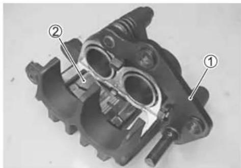
natural_image
Mechanical component with labeled parts (① and ②), no visible text or symbols beyond labels
natural_image
Close-up of a hand using a pliers to adjust or install a mechanical component (no visible text or symbols)
natural_image
Close-up of a gloved hand holding a mechanical component with multiple circular eyes (no visible text or symbols)CALIPER INSPECTION
BRAKE CALIPER
Inspect the brake caliper cylinder wall for nicks, scratches and other damage. If any damage is found, replace the caliper with a new one.
BRAKE CALIPER PISTON
Inspect the brake caliper piston surface for any scratches and other damage. If any damage is found, replace the caliper piston with a new one.
CALIPER HOLDER
- Inspect the caliper holder for damage. If any damage is found, replace it with a new one.
RUBBER PARTS
Inspect the rubber parts for damage. If any damage is found, replace them with the new ones.

natural_image
Close-up of mechanical components with two transparent cylindrical parts and directional arrows indicating features (no text or symbols visible)
natural_image
Two metallic cylindrical objects with textured surfaces, placed on a plain surface (no text or symbols visible)
natural_image
Mechanical linkage component with two articulated arms and a central shaft (no visible text or symbols)
natural_image
Close-up of a mechanical component with two threaded ports and a central housing, showing no visible text or symbols.CALIPER REASSEMBLY AND REMOUNTING
Reassemble the caliper in the reverse order of removal and disassembly. Pay attention to the following points:
- Wash the caliper bores and pistons with specified brake fluid. Particularly wash the dust seal grooves and piston seal grooves.

Specification and Classification: DOT 4
CAUTION
* Wash the caliper components with fresh brake fluid before reassembly. Never use cleaning solvent or gasoline to wash them.
* Do not wipe the brake fluid off after washing the components with a rag.
* When washing the components, use the specified brake fluid. Never use different types of fluid or cleaning solvent such as gasoline, kerosine or the others.
* Replace the piston seals and dust seals with the new ones when reassembly.
* Apply the brake fluid to both seals when installing them.

natural_image
Simple line drawing of a brake fluid container and two cylindrical vials on a tray (no text or symbols)PISTON SEAL
• Install the piston seals as shown in the illustration.
• Install the piston to the caliper.
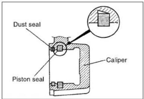
CALIPER HOLDER
- Apply SUZUKI SILICONE GREASE to the caliper holder pin.
99000-25100: SUZUKI SILICONE GREASE
• Install the caliper holder to the caliper.

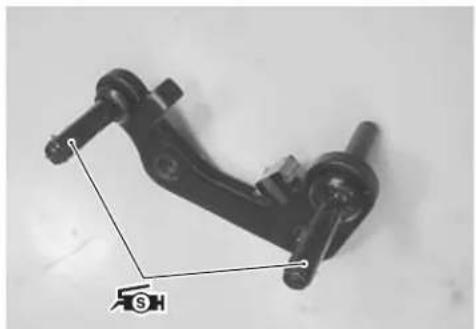
natural_image
Mechanical linkage component with a compass needle pointing to the base (no text or symbols visible)• Install the pad spring①.
• Install the brake pads. (6-57)
NOTE:
Before remounting the caliper, push the piston all the way into the caliper.
- Remount the brake caliper to the front fork.
- Tighten each bolt to the specified torque.

Front brake caliper mounting bolt②:
39 N·m (3.9 kgf-m, 28.0 lb-ft)
Front brake hose union bolt ③:
23 N·m (2.3 kgf-m, 16.5 lb-ft)
CAUTION
* The seal washers should be replaced with the new ones to prevent fluid leakage.
* Bleed air from the system after reassembling the caliper. (2-24)

natural_image
Close-up of mechanical components with a numbered annotation (1) pointing to a specific part, no readable text or symbols present.
Visually check the brake disc for damage or cracks.
Measure the thickness with a micrometer.
Replace the disc if the thickness is less than the service limit or if damage is found.

Front disc thickness: Service Limit: 4.5 mm (0.18 in)

09900-20205: Micrometer (0 - 25 mm)

natural_image
Technical line drawing of a car tire assembly with a screwdriver inserted (no text or symbols)Measure the runout with a dial gauge.
Replace the disc if the runout exceeds the service limit.

Front disc runout: Service Limit: 0.30 mm (0.012 in)

09900-20607: Dial gauge (1/100 mm)
09900-20701: Magnetic stand
* Brake disc removal (6-9)
* Brake disc installation (6-12)

natural_image
Technical line drawing of a car wheel assembly with a pressure gauge attached (no text or symbols)MASTER CYLINDER REMOVAL AND DISASSEMBLY
- Remove the rear view mirror and brake lever cover.
- Drain the brake fluid. (6-58)
- Disconnect the front brake light switch coupler ①.
- Place a rag underneath the union bolt on the master cylinder to catch any spilt brake fluid. Remove the brake hose union bolt and disconnect the brake hose.
CAUTION
Immediately and completely wipe off any brake fluid contacting any part of the motorcycle. The fluid reacts chemically with paint, plastics and rubber materials, etc. and will damage them severely.
- Remove the master cylinder.
- Remove the brake lever ② and brake switch ③.
- Pull out the dust boot ④ and remove the snap ring ⑤.
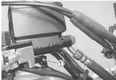
natural_image
Close-up of a motorcycle's front wheel assembly with visible hoses and components (no text or symbols)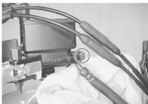
natural_image
Close-up of a medical or laboratory setup with wires and a device, no visible text or symbols
natural_image
Close-up of a motorcycle's front-mounted control panel with buttons and gauges (no visible text or symbols)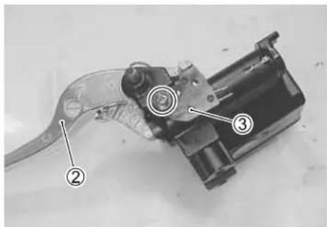
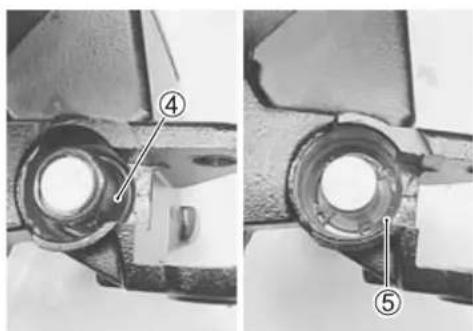
natural_image
Close-up of mechanical components with numbered annotations (4 and 5), no readable text or symbols present.- Remove the piston and return spring.
⑥ Piston
⑦ Secondary cup
⑧ Primary cup
⑨ Return spring
MASTER CYLINDER INSPECTION
Inspect the master cylinder bore for any scratches or other damage.
Inspect the piston surface for any scratches or other damage. Inspect the primary cup, secondary cup and dust seal for wear or damage.
MASTER CYLINDER REASSEMBLY AND REMOUNTING
Reassemble the master cylinder in the reverse order of removal and disassembly. Pay attention to the following points:
CAUTION
* Wash the master cylinder components with fresh brake fluid before reassembly. Never use cleaning solvent or gasoline to wash them.
* Do not wipe the components with a rag.
* Apply brake fluid to the cylinder bore and all the component to be inserted into the bore.

Specification and Classification: DOT 4
- Apply brake fluid to the piston and cups.
• Install the following parts to the master cylinder.
① Dust boot
② Snap ring
③ Secondary cup
④ Piston
⑤ Primary cup
⑥ Return spring


natural_image
Illustration of a brake fluid bottle above a tray with two small objects (no text or symbols)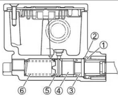
- When remounting the brake master cylinder onto the handlebars, align the master cylinder holder's mating surface Ⓐ with punch mark Ⓑ on the handlebars and tighten the upper clamp bolt first as shown.

Front brake master cylinder mounting bolt:
10 N·m (1.0 kgf-m, 7.0 lb-ft)
- Tighten the union bolt. (Brake hose routing: 8-24)

Brake hose union bolt: 23 N·m (2.3 kgf-m, 16.5 lb-ft)
CAUTION
* The seal washers should be replaced with the new ones to prevent fluid leakage.
* Bleed air from the system after reassembling the master cylinder. (2-24)


natural_image
Close-up of a motorcycle's front-mounted sensor module with attached hoses and a circular annotation highlighting the component (no readable text or symbols)REAR BRAKE CONSTRUCTION

U
| ITEM N·m kgf.m lb-ft | |||
| A | 23 2.3 | 16.5 | |
| B | 10 1.0 | 7.0 | |
| C | 18 1.8 | 13.0 | |
| D | 7.5 0.75 | 6.5 | |
| E | 23 2.3 | 16.53 | |
| F | 17 1.7 | 12.5 | 1 |
| G | 27 2.7 | 19.5 | 9 |
| H | 2.5 0.25 | 1.8 | 1 |
① Brake hose
② Diaphragm
③ Reservoir tank hose
④ Piston/cup set
⑤ Push rod
⑥ Dust boot
⑦ Piston seal
⑧ Dust seal
⑨ Piston
⑩ Pad shim
⑪ Pad insulator
⑫ Brake pad
⑬ Brake pad spring
⑭ Callper bracket
⑮ Caliper
Ⓐ Brake hose union bolt
⑧ Rear brake master cylinder mounting
© Rear brake master cylinder rod lock nut
D Air bleeder valve
E Brake caliper mounting bolt
⑤ Pad mounting pin
© Brake caliper sliding pin
H Plug

WARNING
* This brake system is filled with an ethylene glycol-based DOT 4 brake fluid. Do not use or mix different types of fluid such as silicone-based or petroleum-based.
* Do not use any brake fluid taken from old, used or unsealed containers. Never reuse brake fluid left over from the last servicing or stored for long periods.
* When storing the brake fluid, seal the container completely and keep away from children.
* When replenishing brake fluid, take care not to get dust into fluid.
* When washing brake components, use fresh brake fluid. Never use cleaning solvent.
* A contaminated brake disc or brake pad reduces braking performance. Discard contaminated pads and clean the disc with high quality brake cleaner or neutral detergent.
CAUTION
Handle brake fluid with care: the fluid reacts chemically with paint, plastics, rubber materials etc. and will damage them severely.
BRAKE PAD REPLACEMENT
- Remove the plug ①.
- Loosen the pad mounting pin ②.
- Remove the caliper bracket bolt ③.
CAUTION
* Do not operate the brake pedal while dismounting the pads.
* Replace the brake pads as a set, otherwise braking performance will be adversely affected.
- Remove the pad mounting pin and brake pads with the rear caliper pivoted up.
- Clean up the caliper especially around the caliper pistons.
- Assemble the new brake pad ④, insulator ⑤ and shim ⑥.
CAUTION
Replace the brake pads as a set, otherwise braking performance will be adversely affected.
• Install the new brake pads.

natural_image
Close-up of a mechanical brake assembly with no visible text or symbols
natural_image
Mechanical assembly diagram showing three labeled components (②, ③, ②) without any readable text or symbols.
natural_image
Close-up of a hand adjusting a brake caliper with a valve and adjustment knob (no visible text or symbols)
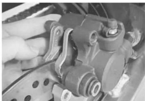
natural_image
Close-up of a hand adjusting automotive brake calipers and components (no visible text or symbols)NOTE:
Make sure that the detent of the pad is seated onto the retainer on the caliper bracket.
- Tighten the caliper mounting bolt ⑦ and pad mounting pin ⑧ to the specified torque.

Rear brake caliper mounting bolt:
23 N·m (2.3 kgf-m, 16.5 lb-ft)
Rear brake pad mounting pin:
17 N·m (1.7 kgf-m, 12.5 lb-ft)
• Install the plug ⑨ to the specified torque.

Pad pin plug: 2.5 N·m (0.25 kgf-m, 1.8 lb-ft)
NOTE:
After replacing the brake pads, pump the brake pedal several times in order to operate the brake correctly and then check the brake fluid level.
BRAKE FLUID REPLACEMENT
- Remove the right frame cover. (6-5)
- Remove the brake fluid reservoir cap.
- Replace the brake fluid in the same manner as the front brake. (6-58)

Specification and Classification: DOT 4
CAUTION
Bleed air from the brake system. (2-24)
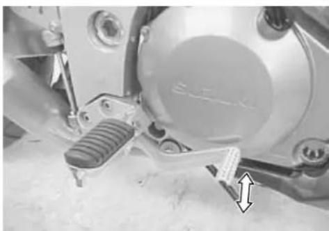
natural_image
Close-up of a mechanical assembly with a circular component and lever mechanism (no visible text or symbols)
natural_image
Close-up of a mechanical component with a tool and a circular component, no visible text or symbols

natural_image
Close-up of a mechanical brake assembly with labeled component (no readable text or symbols)
natural_image
Close-up of hands operating a mechanical component with no visible text or symbols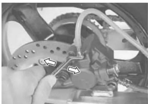
natural_image
Close-up of a mechanical assembly with no visible text or symbolsCALIPER REMOVAL AND DISASSEMBLY
- Drain the brake fluid. (6-68)
- Remove the brake pads. (6-67)
- Place a rag underneath the union bolt to catch any spilt brake fluid.
- Disconnect the brake hose by removing the brake hose union bolt.
CAUTION
Do not reuse the brake fluid left over from previous servicing and stored for long periods.
WARNING
Brake fluid, if it leaks, will interfere with safe running and discolor painted surfaces. Check the brake hose and hose joints for cracks and fluid leakage.
- Pivot the caliper up and remove the caliper from the caliper bracket.
- Remove the pad spring ①.
- Remove the spacer ② and boot ③ from the caliper.

natural_image
Close-up of a mechanical assembly with no visible text or symbols
natural_image
Close-up of hands assembling a mechanical component with a circular arrow indicating rotation (no visible text or symbols)
natural_image
Mechanical component diagram showing internal parts and a labeled section (①), no readable text or symbols present.
- Remove the slide pin ④.
- Place a rag over the piston to prevent it from popping out and then force out the piston using compressed air.
CAUTION
Do not use high pressure air to prevent piston damage.
- Remove the dust seal ⑤ and piston seal ⑥.
CAUTION
Do not reuse the dust seal and piston seal to prevent fluid leakage.
CALIPER INSPECTION
BRAKE CALIPER
Inspect the brake caliper cylinder wall for nicks, scratches and other damage. If any damage is found, replace the caliper with a new one.
BRAKE CALIPER PISTON
Inspect the brake caliper piston surface for any scratches and other damage. If any damage is found, replace the caliper piston with a new one.

natural_image
Close-up of a mechanical component with a numbered annotation pointing to a specific part (no readable text or symbols)
natural_image
Hand holding a camera module with cleaning cloth (no visible text or symbols)
natural_image
Close-up of a mechanical component with numbered annotations (5 and 6) pointing to internal features (no readable text or symbols beyond labels)
natural_image
Close-up of a mechanical component with a highlighted cylindrical part and an arrow pointing to it (no visible text or symbols)
natural_image
Metallic cylindrical object on a plain background (no text or symbols visible)BRAKE CALIPER SLIDING PIN
Inspect the brake caliper sliding pin for wear and other damage. If any damage is found, replace the sliding pin with a new one.

natural_image
Close-up of a black mechanical component with threaded end and flange (no visible text or symbols)Inspect the boot and spacer for damage and wear. If any damage is found, replace boot and spacer with new ones.

natural_image
Two metallic cylindrical mechanical components, one with flange and the other with cap (no text or symbols visible)Inspect the rear brake disc in the same manner as the front brake disc. (6-52)

Service Limit
Rear disc thickness: 4.5 mm (0.18 in)
Rear disc runout: 0.30 mm (0.012 in)
* Brake disc removal (6-34)
* Brake disc installation (6-40)
CALIPER REASSEMBLY AND REMOUNTING
Reassemble and remount the caliper in the reverse order of removal and disassembly. Pay attention to the following points:
CAUTION
* Wash the caliper components with fresh brake fluid before reassembly. Never use cleaning solvent or gasoline to wash them.
* Apply brake fluid to the caliper bore and piston to be inserted into the bore.

Specification and Classification: DOT 4
PISTON SEAL
• Install the piston seals as shown in the right illustration.
• Install the piston to the caliper.
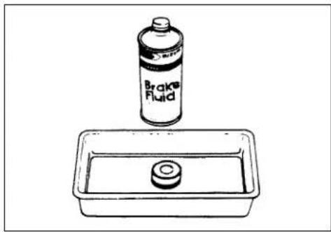
natural_image
Simple line drawing of a brake fluid container above a rectangular basin (no text or symbols)
SLIDING PIN
- Install the boot ①.
- Apply SUZUKI SILICONE GREASE to the inside of the boot.

99000-25100: SUZUKI SILICONE GREASE
- Install the spacer ②.

- Tighten the sliding pin ③ to the specified torque.

Brake caliper sliding pin: 27 N·m (2.7 kgf·m, 19.5 lb·ft)
- Apply SUZUKI SILICONE GREASE to the sliding pin.

99000-25100: SUZUKI SILICONE GREASE

• Install the caliper to the caliper bracket ④.
- Set the boot onto the sliding pin securely.
• Install the brake pad. (6-67)
- Tighten the brake hose union bolt with the brake hose union pipe seated in the cutout on the caliper. (Rear brake hose routing: 8-25)
Brake hose union bolt: 23 N·m (2.3 kgf·m, 16.5 lb·ft) CAUTION
* The seal washers should be replaced with the new ones to prevent fluid leakage.
* Bleed air from the system after reassembling the caliper. (2-24)
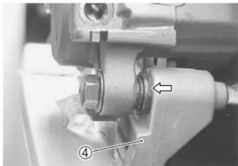
natural_image
Close-up of a mechanical assembly with numbered components (4 and an arrow), no visible text or symbols.
natural_image
Close-up of a mechanical assembly with no visible text or symbolsMASTER CYLINDER REMOVAL AND DISASSEMBLY
- Drain the brake fluid. (6-68)
- Remove the brake fluid reservoir tank mounting bolt ①.

natural_image
Close-up of a mechanical assembly with labeled component (1), no visible text or symbols- Loosen the lock nut ②.
- Remove the master cylinder mounting bolts ③.

natural_image
Mechanical assembly diagram showing two components with numbered callouts (no text or symbols present)- Place a rag underneath the union bolt on the master cylinder to catch spilled drops of brake fluid. Remove the union bolt ④ and disconnect the brake hose.
- Disconnect the reservoir tank hose.
CAUTION
Immediately and completely wipe off any brake fluid contacting any parts of the motorcycle. The fluid reacts chemically with paint, plastic and rubber materials, etc. and will damage them severely.
- Remove the master cylinder by turning the master cylinder rod.
- Disconnect the reservoir hose.
- Remove the connector ⑤ by removing the snap ring ⑥.
- Remove the O-ring ⑦.
CAUTION
Replace the O-ring with a new one.
- Pull out the dust boot ⑧, then remove the snap ring ⑨.
- Remove the push rod, piston/primary cup and spring.
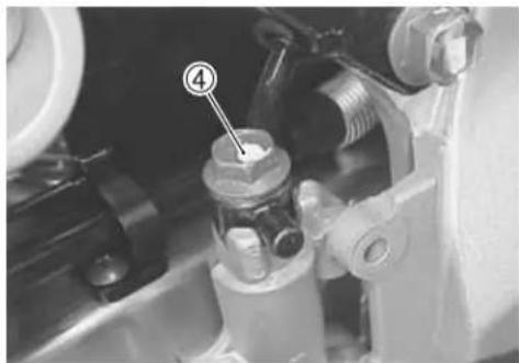
natural_image
Close-up mechanical assembly showing a bolt and housing component (no visible text or symbols)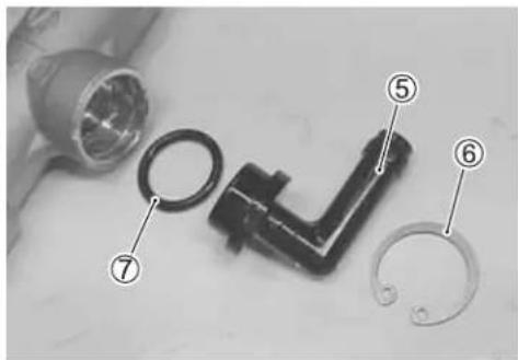

natural_image
Close-up of hands performing a mechanical assembly, showing two steps with numbered annotations (8 and 9) indicating step 8 and step 9 respectively.MASTER CYLINDER INSPECTION
CYLINDER, PISTON AND CUP SET
Inspect the cylinder bore wall for any scratches or other damage.
Inspect the cup set and each rubber part for damage.

natural_image
Technical line drawings of a mechanical component and its corresponding spring assembly (no text or symbols)MASTER CYLINDER REASSEMBLY AND REMOUNTING
Reassemble and remount the master cylinder in the reverse order of removal and disassembly. Pay attention to the following points:
CAUTION
* Wash the master cylinder components with fresh brake fluid before reassembly. Never use cleaning solvent or gasoline to wash them.
* Do not wipe the components with a rag.
* Apply brake fluid to the cylinder bore and all the component to be inserted into the bore.
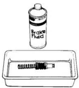

Specification and Classification: DOT 4
- Apply brake fluid to the piston/cup set.
• Install the following parts.
① Spring
② Piston/primary cup
③ Push rod
④ Snap ring
⑤ Dust boot
- Apply the SUZUKI MOLY PASTE to the push rod.

99000-25140: SUZUKI MOLY PASTE
- Install the O-ring ⑥, connector ⑦ and snap ring ⑧ to the master cylinder.
CAUTION
Replace the removed O-ring with a new one.
• Install the master cylinder.
- Tighten the lock nut ⑨.

Rear master cylinder rod lock nut:
18 N·m (1.8 kgf-m, 13.0 lb-ft)


natural_image
Close-up mechanical assembly showing a valve inserted into a housing component (no visible text or symbols)• Install the reservoir tank and reservoir tank hose. (Rear brake hose routing: 8-25)
- Temporarily install the master cylinder to the frame.
- Connect the brake hose to the master cylinder. (Rear brake hose routing: 8-25)
- Tighten the brake hose union bolt to the specified torque.

Brake hose union bolt: 23 N·m (2.3 kgf-m, 16.5 lb-ft)
CAUTION
* The seal washers should be replaced with the new ones to prevent fluid leakage.
* Bleed air from the system after reassembling the master cylinder. (2-24)
- Adjust the brake pedal height. (2-23)
- Reinstall the master cylinder.
- Tighten the master cylinder mounting bolts to the specified torque.

Rear master cylinder mounting bolt:
10 N·m (1.0 kgf-m, 7.0 lb-ft)

natural_image
Close-up of a mechanical component with a circled detail, no visible text or symbols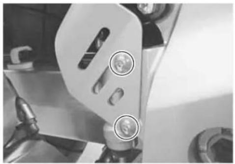
natural_image
Close-up of mechanical components with circular annotations (no readable text or symbols)CLUTCH RELEASE CYLINDER AND MASTER CYLINDER CONSTRUCTION

① Diaphragm
② Push rod
③ Dust boot
④ Piston/cup set
⑤ Clutch hose
⑥ Clutch push rod
⑦ Piston
⑧ Piston cup
⑨ Spring
⑩ Clutch release cylinder
Ⓐ Clutch master cylinder mounting bolt
B Clutch hose union bolt
© Air bleeder valve
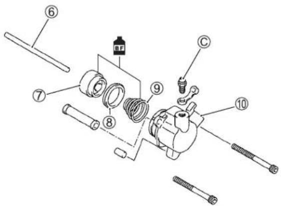

| ITEM N·m kgf·m lb·ft | |||
| A | 10 1.0 | 7.0 | |
| B | 23 2.3 | 16.5 | |
| C | 7.5 | 0.75 5.5 | |
WARNING
* This clutch system is filled with an ethylene glycol-based DOT 4 brake fluid. Do not use or mix different types of fluid such as silicone-based or petroleum-based.
* Do not use any brake fluid taken from old, used or unsealed containers. Never reuse brake fluid left over from the last servicing or stored for long periods.
* When storing the brake fluid, seal the container completely and keep away from children.
* When replenishing brake fluid, take care not to get dust into fluid.
* When washing brake components, use fresh brake fluid. Never use cleaning solvent.
CAUTION
Handle brake fluid with care: the fluid reacts chemically with paint, plastics, rubber materials etc. and will damage them sererly.
CLUTCH FLUID REPLACEMENT
- Place the motorcycle on a level surface and keep the handlebars straight.
- Remove the master cylinder reservoir cap and diaphragm.
- Suck up the old clutch fluid as much as possible from the reservoir tank.
- Fill the reservoir with the new clutch fluid.

Specification and Classification: DOT 4
- Connect a clear hose to the clutch release cylinder air bleeder valve and insert the other end of hose into a receptacle.
- Loosen the air bleeder valve and pump the clutch lever until old clutch fluid flows out of the bleeder system.
- Close the clutch release cylinder air bleeder valve, and disconnect a clear hose. Fill the reservoir with fresh brake fluid to the upper level.
CAUTION
Bleed air in the clutch fluid system. (2-16)

natural_image
Close-up of a mechanical assembly with hoses and components (no visible text or symbols)
natural_image
Close-up of a hand using a tool to adjust or install a mechanical component, with arrows indicating direction (no visible text or symbols)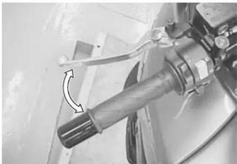
natural_image
Close-up of a mechanical component with a curved arrow indicating rotation (no visible text or symbols)CLUTCH RELEASE CYLINDER REMOVAL AND DISASSEMBLY
- Drain the clutch fluid. (above)
- Disconnect the clutch hose by removing the union bolt ①.
NOTE:
Place a rag underneath the union bolt on the release cylinder to catch any split brake fluid.
- Remove the clutch release cylinder ②.
CAUTION
Do not reuse the brake fluid left over from previous servicing and stored for long periods of time.

WARNING
Brake fluid, if it leaks, will interfere with safe running and discolor painted surfaces. Check the brake hose and hose joints for cracks and fluid leakage.
- Place a rag over the piston to prevent it from popping out.
- Force out the piston by using compressed air.
CAUTION
Do not use high pressure air to prevent piston damage.

natural_image
Line drawing of a hand holding a magnifying glass over a circular object (no text or symbols)CLUTCH RELEASE CYLINDER INSPECTION
Inspect the clutch release cylinder bore wall for nicks, scratches or other damage. Inspect the oil seal for damage and wear. Inspect the piston surface for any scratches or other damage.

natural_image
Close-up of a mechanical component with a central cylindrical housing and mounting flanges (no visible text or symbols)
natural_image
Close-up of a mechanical spring component with metallic housing (no text or symbols visible)CLUTCH RELEASE CYLINDER REASSEMBLY AND REMOUNTING
Reassemble the clutch release cylinder in the reverse order of disassembly and by taking the following steps:
CAUTION
* Wash the clutch cylinder components with fresh brake fluid before reassembly. Never use cleaning solvent or gasoline to wash them.
* Do not wipe the components with a rag.
* Apply brake fluid to the cylinder bore and piston to be inserted into the bore.
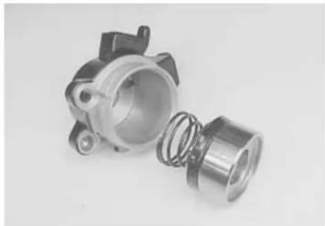
natural_image
Close-up of a metallic automotive engine component with a coiled spring and housing (no text or symbols visible)
Specification and Classification: DOT 4
① Piston
② Piston cup
③ Spring
④ Air bleeder valve
⑤ Bleeder cap
⑥ Clutch ralease cylinder body
- Apply SUZUKI SILICONE GREASE to the concavity of piston.

99000-25100: SUZUKI SILICONE GREASE
• Install the clutch release cylinder⑦ and spacer ⑧.
- Tighten each bolt to the specified torque.

Clutch hose union bolt: 23 N·m (2.3 kgf·m, 16.5 lb·ft) Air bleeder valve ⑩: 7.5 N·m (0.75 kgf·m, 5.5 lb·ft)
CAUTION
* The seal washers should be replaced with the new ones to prevent fluid leakage.
* Bleed air from the system after reassembling the release cylinder. (2-16)

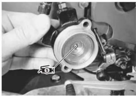
natural_image
Close-up of a hand adjusting a mechanical component with a screwdriver inserted (no visible text or symbols)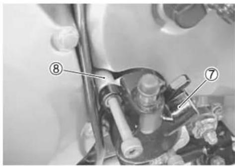

CLUTCH MASTER CYLINDER REMOVAL AND DISASSEMBLY
- Remove the rear view mirror and clutch lever cover.
- Drain the clutch fluid. (6-78)
- Disconnect the clutch lever position switch lead wires.
- Place a rag underneath the union bolt on the master cylinder to catch spilled drops of brake fluid. Remove the union bolt and disconnect the clutch hose from the master cylinder.
- Remove the clutch master cylinder.
CAUTION
Completely wipe off any brake fluid adhering to any parts of motorcycle. The fluid reacts chemically with paint, plastics, rubber materials, etc. and will damage them severely.
- Remove the clutch lever ① and clutch lever position switch ②.
- Remove the boot ③ and push rod ④.
-
Remove the snap ring ⑤.
-
Remove the piston/cup set
⑥ Secondary cup
⑦ Piston
⑧ Primary cup
⑨ Spring
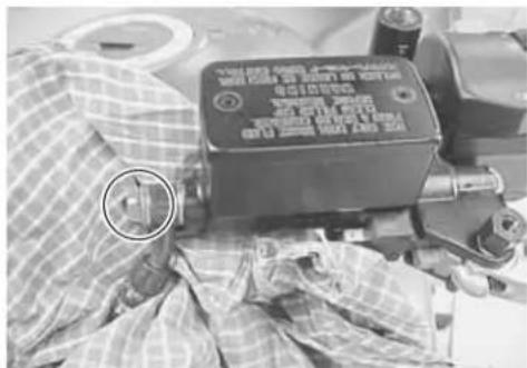
natural_image
Close-up of a mechanical component with a checkered cloth and plastic sheet, no visible text or symbols.
natural_image
Close-up of a motorcycle's front wheel and grip mechanism with three circular buttons (no visible text or symbols)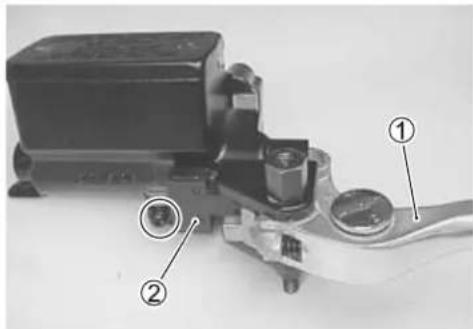

natural_image
Close-up of mechanical components with numbered callouts (3, 4, 5), no visible text or symbols beyond labels
CLUTCH MASTER CYLINDER INSPECTION
Inspect the piston surface for any scratches or other damage. Inspect the primary cup, secondary cup and dust seal for wear or damage.
Inspect the master cylinder bore for any scratches or other damage.
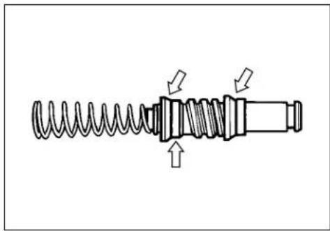
natural_image
Diagram of a mechanical spring assembly with directional arrows indicating motion (no text or labels)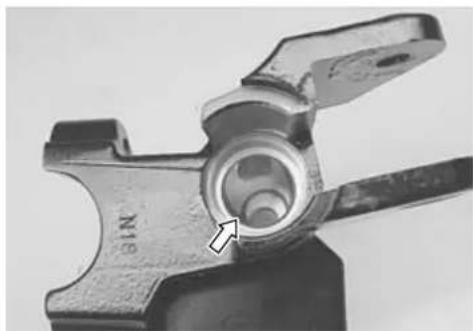
natural_image
Close-up of a mechanical tool with a circular component and an arrow pointing to it (no visible text or symbols)CLUTCH MASTER CYLINDER REASSEMBLY AND REMOUNTING
Reassemble the master cylinder in the reverse order of removal and disassembly. Pay attention to the following points:
CAUTION
* Wash the master cylinder components with fresh brake fluid before reassembly. Never use cleaning solvent or gasoline to wash them.
* Do not wipe the components with a rag.
Apply brake fluid to the cylinder bore and all the component to be inserted into the bore.

natural_image
Simple line drawing of a paint can and a plastic bottle in a tray (no text or symbols)
Specification and Classification: DOT 4
- Apply brake fluid to the piston/cup set and install them to the clutch master cylinder.
① Spring
② Primary cup
③ Piston
④ Secondary cup
⑤ Stopper plate
⑥ Snap ring
⑦ Dust boot
⑧ Push rod

- Apply SUZUKI MOLY PASTE to the push rod.
• Install the push rod and dust boot.

99000-25140: SUZUKI MOLY PASTE
- When remounting the master cylinder on the handlebars, align the master cylinder holder's mating surface Ⓐ with punched mark Ⓑ on the handlebars and tighten the upper clamp bolt first. - Tighten the clutch master cylinder union bolt to the specified torque.

Clutch master cylinder mounting bolt:
10 N·m (1.0 kgf-m, 7.0 lb-ft)
Clutch master cylinder union bolt:
23 N·m (2.3 kgf-m, 16.5 lb-ft)
- Connect the clutch lever position switch lead wire. (Clutch hose routing: 8-22)
CAUTION
* The seal washers should be replaced with the new ones to prevent fluid leakage.
* Bleed air from the system after reassembling the master cylinder. (2-16)
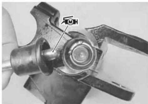

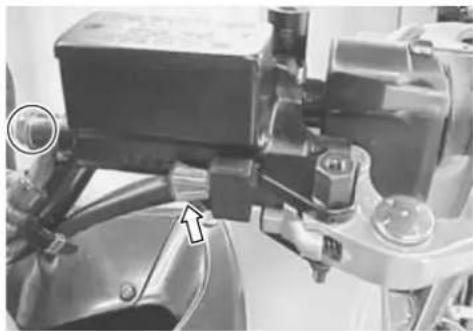
natural_image
Close-up of a mechanical assembly with no visible text or symbolsTIRE AND WHEEL TIRE REMOVAL
The most critical factor of a tubeless tire is the seal between the wheel rim and the tire bead. For this reason, it is recommended to use a tire changer that can satisfy this sealing requirement and can make the operation efficient as well as functional.
For operating procedures, refer to the instructions supplied by the tire changer manufacturer.
NOTE:
When removing the tire in the case of repair or inspection, mark the tire with a chalk to indicate the tire position relative to the valve position.
Even though the tire is refitted to the original position after repairing puncture, the tire may have to be balanced again since such a repair can cause imbalance.
INSPECTION
WHEEL
Wipe the wheel clean and check for the following:
* Distortion and crack
* Any flaws and scratches at the bead seating area.
* Wheel rim runout (6-10)
TIRE
Tire must be checked for the following points:
* Nick and rupture on side wall
* Tire tread depth (2-25)
* Tread separation
* Abnormal, uneven wear on tread
* Surface damage on bead
* Localized tread wear due to skidding (Flat spot)
* Abnormal condition of inner liner

natural_image
Diagram of a curved track with directional arrows indicating movement or flow (no text or symbols)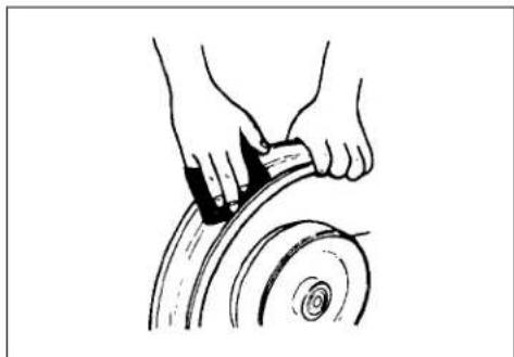
natural_image
Line drawing of hands using a tool to cut a circular object (no text or symbols)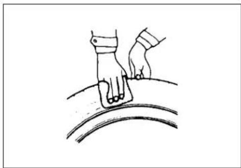
natural_image
Simple line drawing of a hand pressing down on a curved surface (no text or symbols)
natural_image
Diagram of a light bulb with a hand pointing to its tip, showing internal structure and outline (no text or symbols)VALVE
- Inspect the valve after the tire is removed from the rim. Replace the valve with a new one if the seal rubber is peeling or has damage.
- Inspect the valve core. If the seal has abnormal deformation, replace the valve with a new one.

natural_image
Diagram of a mechanical component with a downward arrow indicating a feature, no text or symbols present
VALVE INSTALLATION
- Any dust or rust around the valve hole must be cleaned off. Then install the valve in the rim.
NOTE:
To properly install the valve into the valve hole, apply a special tire lubricant or neutral soapy liquid to the valve.
CAUTION
Be careful not to damage the lip of valve.

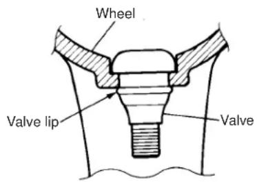
TIRE INSTALLATION
- Apply tire lubricant to the tire bead.
- When installing the tire onto the wheel, observe the following points.
CAUTION
* Do not reuse the valve which has been once removed.
* Do not use oil, grease or gasoline on the tire bead in place of tire lubricant.

natural_image
Simple line drawing of a hand holding a ring with a tool, no text or symbols present- When installing the tire, the arrow ① on the side wall should point to the direction of wheel rotation.
-
Align the chalk mark put on the tire at the time of removal with the valve position.
-
For installation procedure of tire onto the wheel, follow the instructions given by the tire changer manufacturer.
- Bounce the tire several times while rotating. This makes the tire bead expand outward to contact the wheel, thereby facilitating air inflation.
- Inflate the tire.
WARNING
* Do not inflate the tire to more than 400 kPa (4.0kgf/cm²). If inflated beyond this limit, the tire can burst and possibly cause injury. Do not stand directly over the tire while inflating.
* In the case of preset pressure air inflator, pay special care for the set pressure adjustment.
- In this condition, check the "rim line" cast on the tire side walls. The line must be equidistant from the wheel rim all around. If the distance between the rim line and wheel rim varies, this indicates that the bead is not properly seated. If this is the case, deflate the tire completely and unseat the bead for both sides. Coat the bead with lubricant and fit the tire again.
- When the bead has been fitted properly, adjust the pressure to specification.
• As necessary, adjust the tire balance.
CAUTION
Do not run with a repaired tire at a high speed.
DATA
Tire pressure
Solo riding: Front: 250 kPa (2.50 kgf/cm, 36 psi)
Rear: 250 kPa (2.50 kgf/cm 4 , 36 psi)
Dual riding: Front: 250 kPa (2.50 kgf/cm, 36 psi)
Rear: 280 kPa (2.80 kgf/cm 4 , 41 psi)


ELECTRICAL SYSTEM
CONTENTS
CAUTIONS IN SERVICING 7-2
CONNECTOR 7-2
COUPLER 7-2
CLAMP 7-2
FUSE 7-2
SEMI-CONDUCTOR EQUIPPED PART 7-2
BATTERY 7-3
CONNECTING THE BATTERY 7-3
WIRING PROCEDURE 7-3
USING THE MULTI CIRCUIT TESTER 7-3
LOCATION OF ELECTRICAL COMPONENTS 7-4
CHARGING SYSTEM 7-6
TROUBLESHOOTING 7-6
INSPECTION 7-7
STARTER SYSTEM AND SIDE-STAND/IGNITION INTERLOCK
SYSTEM 7-10
TROUBLE SHOOTING 7-10
STARTER MOTOR REMOVAL AND DISASSEMBLY 7-11
STARTER MOTOR INSPECTION 7-12
STARTER MOTOR REASSEMBLY 7-12
STARTER RELAY INSPECTION 7-13
SIDE-STAND/IGNITION INTERLOCK SYSTEM PARTS
INSPECTION 7-14
TROUBLESHOOTING 7-17
INSPECTION 7-19
COMBINATION METER 7-22
REMOVAL AND DISASSEMBLY 7-22
INSPECTION 7-23
ENGINE COOLANT TEMPERATURE METER AND
INDICATOR 7-25
LAMPS 7-29
CAUTIONS IN SERVICING
CONNECTOR
- When connecting a connector, be sure to push it in until a click is felt.
- Inspect the connector for corrosion, contamination and breakage in its cover.

COUPLER
- With a lock type coupler, be sure to release the lock before disconnecting it and push it in fully till the lock works when connecting it.
- When disconnecting the coupler, be sure to hold the coupler itself and do not pull the lead wires.
- Inspect each terminal on the coupler for being loose or bent.
- Inspect each terminal for corrosion and contamination.

CLAMP
- Clamp the wire harness at such positions as indicated in "WIRE HARNESS ROUTING". (8-14 to 8-18)
- Bend the clamp properly so that the wire harness is clamped securely.
- In clamping the wire harness, use care not to allow it to hang down.
- Do not use wire or any other substitute for the band type clamp.
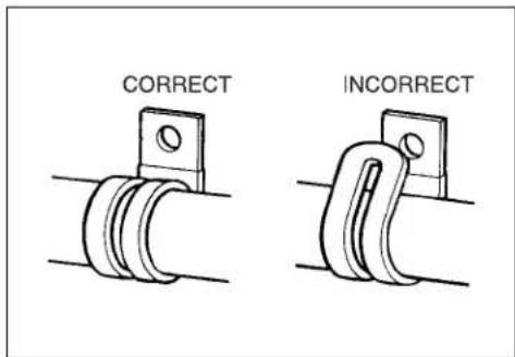
FUSE
- When a fuse blows, always investigate the cause, correct it and then replace the fuse.
- Do not use a fuse of a different capacity.
- Do not use wire or any other substitute for the fuse.

natural_image
Line drawing of a small electronic component with a 10-pin top and four legs (no text or symbols)SEMI-CONDUCTOR EQUIPPED PART
- Be careful not to drop the part with a semi-conductor built in such as a ECM.
- When inspecting this part, follow inspection instruction strictly. Neglecting proper procedure may cause damage to this part.

BATTERY
- The MF battery used in this motorcycle does not require maintenance (e.g., electrolyte level inspection, distilled water replenishment).
- During normal charging, no hydrogen gas is produced. However, if the battery is overcharged, hydrogen gas may be produced. Therefore, be sure there are no fire or spark sources (e.g., short circuit) nearby when charging the battery.
- Be sure to recharge the battery in a well-ventilated and open area.
- Note that the charging system for the MF battery is different from that of a conventional battery. Do not replace the MF battery with a conventional battery.
CONNECTING THE BATTERY
- When disconnecting terminals from the battery for disassembly or servicing, be sure to disconnect the battery lead wire, first.
- When connecting the battery lead wires, be sure to connect the ⊕ battery lead wire, first.
- If the terminal is corroded, remove the battery, pour warm water over it and clean it with a wire brush.
• After connecting the battery, apply a light coat of grease to the battery terminals.
• Install the cover over the ⊕ battery terminal.
WIRING PROCEDURE
- Properly route the wire harness according to the "WIRE ROUTING" section. (8-14 to 8-18)

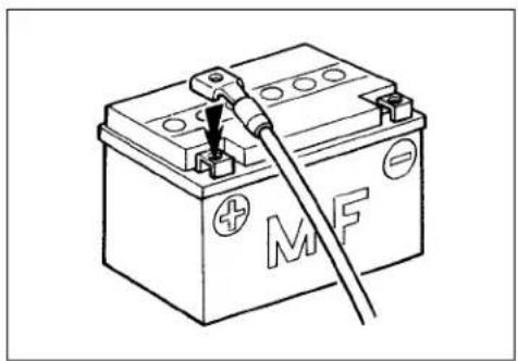
natural_image
Line drawing of a battery with a screwdriver inserted, showing internal components and mounting holes (no text or symbols)USING THE MULTI CIRCUIT TESTER
- Properly use the multi circuit tester⊕ and ⊖ probes. Improper use can cause damage to the motorcycle and tester.
- If the voltage and current values are not known, begin measuring in the highest range.
- When measuring the resistance, make sure that no voltage is applied. If voltage is applied, the tester will be damaged.
• After using the tester, be sure to turn the switch to the OFF position.
CAUTION
Before using the multi circuit tester, read its instruction manual.

natural_image
Technical line drawing of a mechanical device casing with internal components (no text or symbols)LOCATION OF ELECTRICAL COMPONENTS
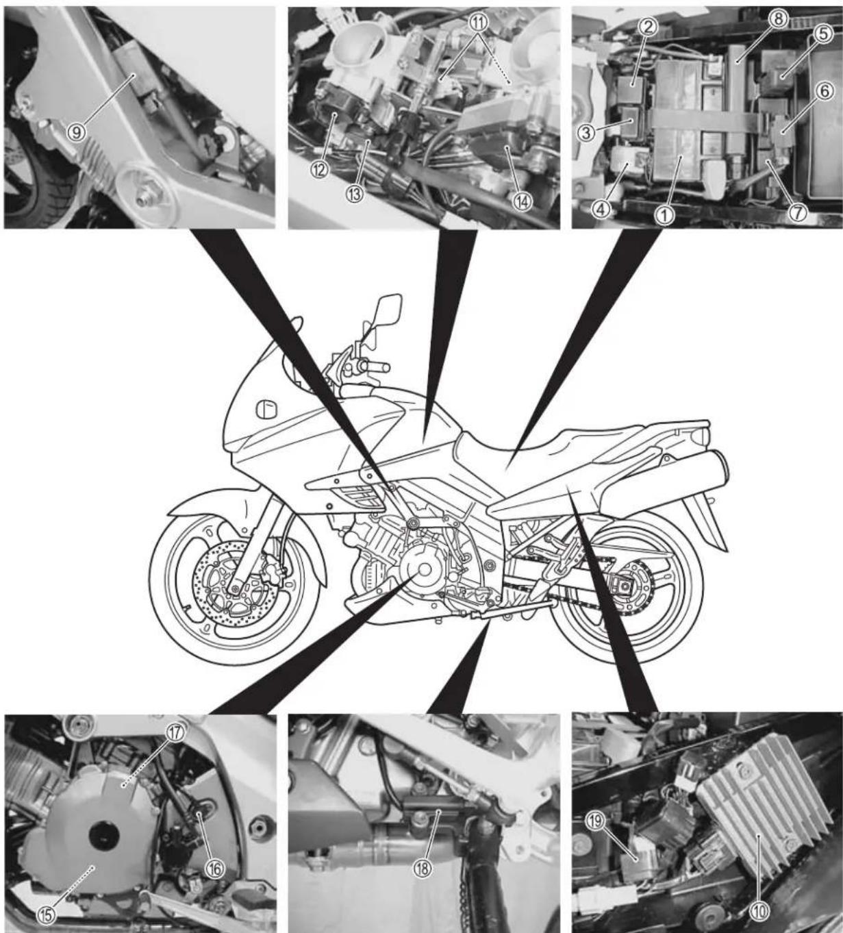
① Battery
② Fuse box
③ Side-stand/turn signal relay
④ Starter relay
⑤ Fuel pump relay
⑥ Tip over sensor (4-42)
⑦ AP sensor (4-40)
⑧ ECM (Engine Control Module)
⑨ Ignition coil (No.2)
⑩ Regulator/rectifier
⑪ Fuel injector (4-47 and 4-70)
⑫ STP sensor (4-44)
⑬ TP sensor (4-36)
⑭ Secondary throttle valve actuator (4-43)
⑮ Generator
⑯ Speedometer sensor
⑰ CKP sensor
⑱ Side stand switch
⑲ Mode selection switch coupler

① ECT sensor (4-38)
② IAP sensor (4-34)
③ IAT sensor (4-39)
④ Starter motor
⑤ CMP sensor (4-32)
⑥ Oil pressure switch
⑦ Fuel pump (4-55)
⑫ Ignition coil (No.1)
CHARGING SYSTEM

flowchart
graph TD
    A["Generator"] --> B["Regulator/rectifier"]
    B --> C["SCR"]
    C --> D["IC"]
    D --> E["Battery"]
    E --> F["Load"]
    F --> G["Ig.switch"]
    G --> H["Ground"]
TROUBLESHOOTING

flowchart
graph TD
    A["Battery runs down quickly."] --> B["Check accessories which use excessive amounts of electricity."]
    B --> C["No accessories"]
    C --> D["Check the battery for current Current leaks: Short circuit of wire harness, Faulty electrical equipment"]
    D --> E["No current leaks"]
    E --> F["Measure the charging voltage between the battery terminals. Correct Faulty battery (7-8) Abnormal driving condition"]
    F --> G["Incorrect"]
    G --> H["Measure the continuity of the generator coil. No continuity (7-8)"]
    H --> I["Continuity"]
    I --> J["Continued on next page"]

    B --> K["Accessories are installed"]
    K --> L["Remove accessories."]

    H --> M["Faulty generator coil or disconnected lead wires"]
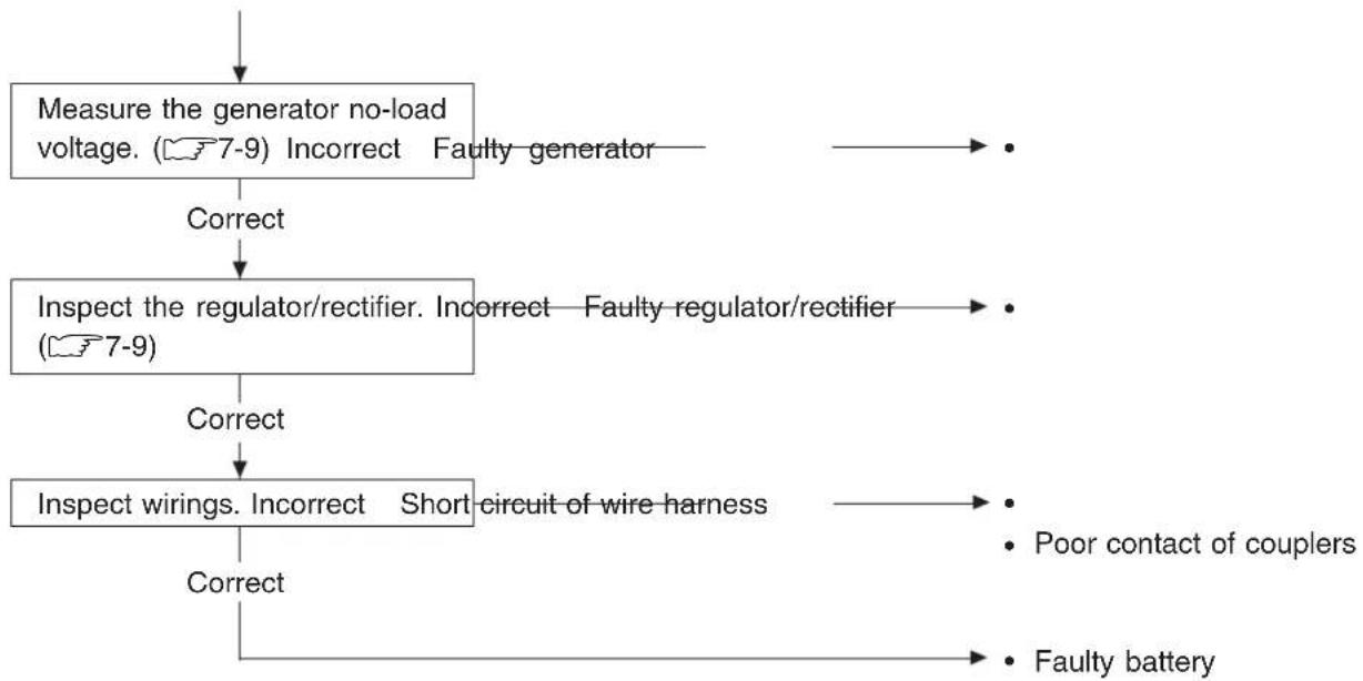
flowchart
graph TD
    A["Measure the generator no-load voltage. (7-9) Incorrect Faulty generator"] --> B["Correct"]
    B --> C["Inspect the regulator/rectifier. Incorrect Faulty regulator/rectifier (7-9)"]
    C --> D["Correct"]
    D --> E["Inspect wirings. Incorrect Short circuit of wire harness"]
    E --> F["Correct"]
    F --> G["Faulty battery"]
    style A fill:#f9f,stroke:#333
    style G fill:#f9f,stroke:#333
Others
Battery overcharge
- Faulty regulator/rectifier
- Faulty battery
- Poor contact of generator lead wire coupler
INSPECTION
BATTERY CURRENT LEAKAGE
- Remove the seat. (6-4)
- Turn the ignition switch to the OFF position.
- Disconnect the battery lead wire.
Measure the current between ⊖ battery terminal and the ⊖ battery lead wire using the multi circuit tester. If the reading exceeds the specified value, leakage is evident.

09900-25008: Multi circuit tester set

Battery current (leak): Under 3 mA

Tester knob indication: Current (---, 20 mA)
CAUTION
* Because the current leak might be large, turn the tester to high range first to avoid tester damage.
* Do not turn the ignition switch to the "ON" position when measuring current.
When checking to find the excessive current leakage, remove the couplers and connectors, one by one, checking each part.

natural_image
Close-up of a multimeter displaying a digital display with measurement markings (no readable text or symbols)
REGULATED VOLTAGE
- Remove the seat. (6-4).
- Start the engine and keep it running at 5 000 r/min. with lighting switch turned ON (only E02, E19) and dimmer switch turned HI position.
Measure the DC voltage between the ⊕ and ⊖ battery terminals using the multi circuit tester. If the voltage is not within the specified value, inspect the generator and regulator/rectifier. (7-8 and 7-9)
NOTE:
When making this test, be sure that the battery is in fully-charged condition.

09900-25008: Multi circuit tester set

Tester knob indication: Voltage (---)

Charging output (Regulated voltage):
14.0 - 15.5 V at 5 000 r/min.
GENERATOR COIL RESISTANCE
- Remove the left frame cover. (6-5)
- Disconnect the generator coupler.
Measure the resistance between the three lead wires.
If the resistance is not specified value, replace the stator with a new one. Also, check that the generator core is insulated.

09900-25008: Multi circuit tester set

Tester knob indication: Resistance (Ω)

Generator coil resistance: 0.2 - 0.5 Ω (Yellow - Yellow) ∞ Ω (Yellow - Ground)
NOTE:
When making above test, it is not necessary to remove the generator.

natural_image
Close-up of an electronic component with visible circuitry and wiring (no text or symbols)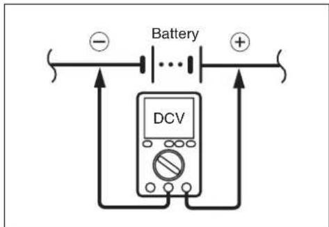

natural_image
Close-up of mechanical components with no visible text or symbols
GENERATOR NO-LOAD PERFORMANCE
- Remove the left frame cover. (6-5)
- Disconnect the generator coupler.
- Start the engine and keep it running at 5 000 r/min.
Using the multi circuit tester, measure the voltage between three lead wires.
If the tester reads under the specified value, replace the generator with a new one.

09900-25008: Multi circuit tester set

Tester knob indication: Voltage (\~)

Generator no-load performance: More than 75 V at 5 000 r/min (When engine is cold)
REGULATOR/RECTIFIER
- Remove the left frame cover. (6-5)
- Remove the regulator/rectifier and disconnect the coupler.


natural_image
Close-up of a mechanical component with circular annotations highlighting features (no readable text or symbols)Measure the voltage between the terminals using the multi circuit tester as indicated in the table below. If the voltage is not within the specified value, replace the regulator/rectifier with a new one.

09900-25008: Multi circuit tester set

Tester knob indication: Diode test (◀)
Unit: V
| Probe of tester to: | + Probe of tester to: | ||||||
| A | B | C | D | E | F | ||
| A | * | 0.4–0.7 | 0.3–0.6 | 0.3–0.6 | 0.3–0.6 | ||
| B | * | * | * | ||||
| C | * | * | * | * | |||
| D | * | * | 0.3–0.6 | * | |||
| E | * | * | 0.3–0.6 | * | |||
| F | * | * | 0.3–0.6 | * | * | ||
* More than 1.4 V (tester's battery voltage)

*
NOTE:
If the tester reads under 1.4 V when the tester probes are not connected, replace the battery of multi circuit tester.
STARTER SYSTEM AND SIDE-STAND/IGNITION INTERLOCK SYSTEM
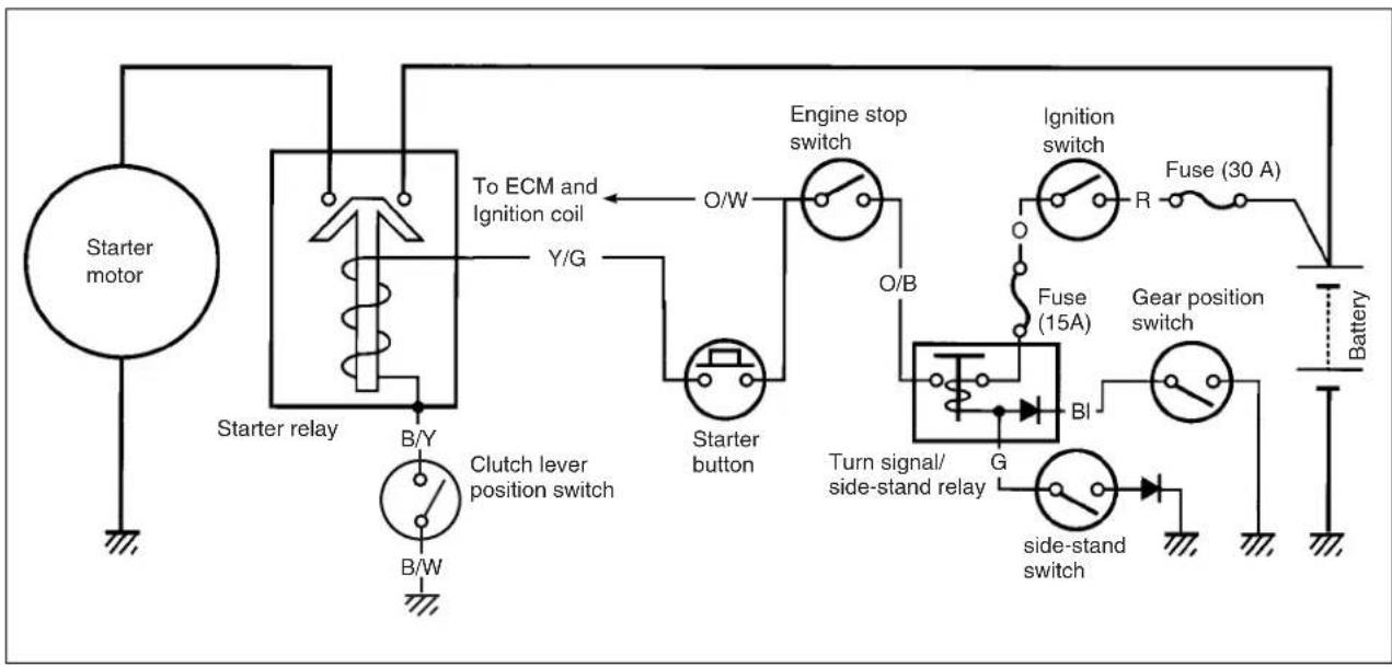
flowchart
graph TD
    A["Starter motor"] --> B["Starter relay"]
    B --> C["To ECM and Ignition coil"]
    C --> D["Y/G"]
    D --> E["Engine stop switch"]
    E --> F["O/W"]
    F --> G["Chutch lever position switch"]
    G --> H["B/Y"]
    H --> I["B/W"]
    I --> J["Starter button"]
    J --> K["Turn signal/ side-stand relay"]
    K --> L["G"]
    L --> M["side-stand switch"]
    M --> N["Side-stand switch"]
    N --> O["BI"]
    O --> P["Fuse (15A)"]
    P --> Q["R"]
    Q --> R["Fuse (30 A)"]
    R --> S["Battery"]
    S --> T["Ignition switch"]
    T --> U["Gear position switch"]
TROUBLE SHOOTING

flowchart
graph TD
    A["Starter motor will not run."] --> B["The transmission is in neutral. Grasp the Check if the starter motor runs clutch lever, turn on the ignition switch when its terminal is connected with the engine stop switch in the "RUN" position and listen for a click from the not use thin "wire" because a starter relay when the starter button is large (amount of current flows) pushed."]
    B -->|No click| C["Measure the starter relay voltage at the starter relay connectors (between Y/G ⊕ and B/Y ⊖) when the starter button is pushed."]
    C -->|Voltage| D["Continued on next page"]
    B -->|Clicks| E["to the battery ⊕ terminal (Do)"]
    E --> F["Runs Does not run"]
    F --> G["Faulty starter motor"]
    G --> H["• Faulty starter relay\n• Loose or disconnected starter motor lead wire\n• Faulty ignition switch\n• Faulty engine stop switch\n• Faulty clutch lever position switch\n• Faulty gear position switch\n• Faulty turn signal/side-stand relay\n• Faulty starter button\n• Poor contact of connector\n• Open circuit in wire harness"]
    E --> I["No voltage"]

flowchart
graph TD
    A["Check the starter relay. (7-13)"] -->|Incorrect| B["Faulty starter relay"]
    A -->|Correct| C["Poor contact of the starter relay"]
The starter motor runs when the transmission is in neutral with the side-stand up or down, but does not run when the transmission is in any position other than neutral with the side-stand down.

flowchart
graph TD
    A["Check the side-stand switch. (7-14)"] --> B{Correct}
    B --> C["Incorrect"]
    C --> D["Faulty side-stand switch"]
    B --> E["Open circuit in wire harness"]
    B --> F["Poor contact of connector"]
    G["Others"] --> E
    G --> F
Engine does not turn though the starter motor runs. • Faulty starter torque limiter (3-64)
STARTER MOTOR REMOVAL AND DISASSEMBLY
- Remove the engine under cover.
- Remove the starter motor and disconnect the starter motor lead wire ①.

natural_image
Mechanical assembly diagram showing internal components with numbered annotations (no readable text or symbols)- Disassemble the starter motor as shown in the illustration.

① O-ring
② Housing
③ Armature
④ Washer
⑤ O-ring
⑥ Starter motor case
⑦ Starter brush holder assembly
⑧ O-ring
STARTER MOTOR INSPECTION
CARBON BRUSH
Inspect the brushes for abnormal wear, cracks, or smoothness in the brush holder.
If any damages are found, replace the brush assembly with a new one.
COMMUTATOR
Inspect the commutator for discoloration, abnormal wear or undercut Ⓐ.
If abnormal wear is found, replace the armature with a new one. If the commutator surface is discolored, polish it with #400 sand paper and wipe it using a clean dry cloth.
If there is no undercut, scrape out the insulator ① with a saw blade.
ARMATURE COIL INSPECTION
Check for continuity between each segment and between each segment and the armature shaft using the multi circuit tester.
If there is no continuity between the segments or there is continuity between the segments and shaft, replace the armature with a new one.

09900-25008: Multi circuit tester set

Tester knob indication: Continuity test (●))
OIL SEAL INSPECTION
Check the oil seal lip for damage or leakage.
If any damage is found, replace the housing end.
STARTER MOTOR REASSEMBLY
Reassemble the starter motor in the reverse order of disassembly. Pay attention to the following points:
- Apply SUSUKI SUPER GREASE "A" to the lip of the oil seal.

99000-25030: SUZUKI SUPER GREASE "A" (USA)
99000-25010: SUZUKI SUPER GREASE "A" (Others)
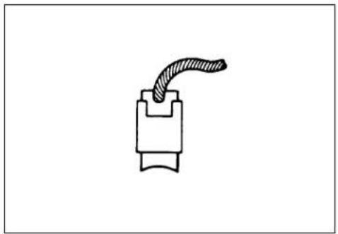
natural_image
Simple line drawing of a mechanical component with a curved handle (no text or symbols)
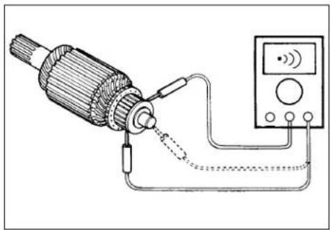
natural_image
Diagram of an electric motor connected to a multimeter via wires, showing wiring and signal output (no text or labels)
natural_image
Close-up of a mechanical component with a central hole and internal gear-like structure, no visible text or symbols.
natural_image
Close-up of a mechanical component with a circular housing and internal blades, labeled 'A' with an arrow pointing to a feature (no text or symbols on the component itself)- Apply a small quantity of SUZUKI MOLY PASTE to the armature shaft.

99000-25140: SUZUKI MOLY PASTE
- Apply a small quantity of THREAD LOCK "1342" to the starter motor housing bolts.

99000-32050: THREAD LOCK "1342"
- Apply SUZUKI SUPER GREASE "A" to the O-ring.

99000-25030: SUZUKI SUPER GREASE "A" (USA) 99000-25010: SUZUKI SUPER GREASE "A" (Others)
- Tighten the starter motor lead wire nut to the specified torque.

Starter motor lend wire nut: 5 N·m (0.5 Kgf·m, 3.7 lb·ft)
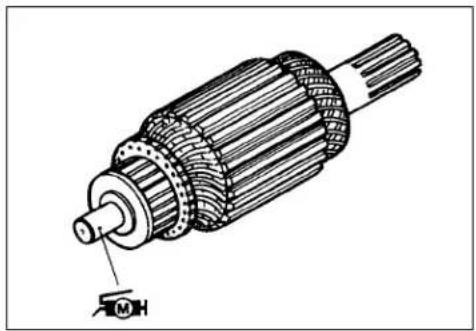
natural_image
Technical line drawing of an electric motor rotor assembly (no text or symbols)

natural_image
Close-up of mechanical components with no visible text or symbolsSTARTER RELAY INSPECTION
- Remove the seat. (6-4)
- Disconnect the battery lead wire from the battery.
- Remove the starter relay cover ①.
- Disconnect the starter relay coupler ②.


- Disconnect the starter motor lead wire ③, battery lead wire ④.
- Remove the starter relay ⑤.
Apply 12 V to Ⓐ and Ⓑ terminals and check for continuity between the positive and negative terminals using the multi circuit tester. If the starter relay clicks and continuity is found, the relay is ok.

09900-25008: Multi circuit tester set

Tester knob indication: Continuity test (●))
CAUTION
Do not apply a battery voltage to the starter relay for more than five seconds, since the relay coil may overheat and damaged.
Measure the relay coil resistance between the terminals using the multi circuit tester. If the resistance is not within the specified value, replace the starter relay with a new one.

09900-25008: Multi circuit tester set

Tester knob indication: Resistance (Ω)

Starter relay resistance: 3 - 6 Ω
SIDE-STAND/IGNITION INTERLOCK SYSTEM PARTS INSPECTION
Check the interlock system for proper operation. If the interlock system does not operate properly, check each component for damage or abnormalities. If any abnormality is found, replace the component with a new one.
SIDE-STAND SWITCH
- Remove the seat. (6-4)
- Remove the left frame cover. (6-5)
- Disconnect the side-stand switch coupler and measure the voltage between Green and Black/White lead wires.

09900-25008: Multi circuit tester set

Tester knob indication: Diode test ( → )
| Green(⊕ Probe) | Black/White(⊖ Probe) | |
| ON(Side-stand up) | 0.4 – 0.6 V | |
| OFF(Side-stand down) | More than 1.4 V(Tester's battery voltage) | |
NOTE:
If the tester reads under 1.4 V when the tester probes are not connected, replace its battery.

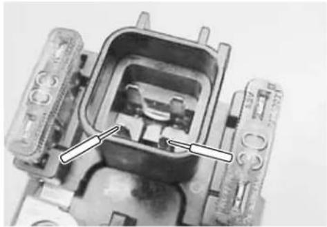
natural_image
Close-up of a mechanical component with internal components and mounting holes (no visible text or symbols)
natural_image
Close-up of a mechanical assembly with visible wiring and components (no text or symbols)
GEAR POSITION SWITCH
- Remove the seat. (6-4)
- Remove the fuel tank front cover.
- Remove the fuel tank side covers.
- Lift and support the fuel tank with the fuel tank prop stay. (4-51)
- Disconnect the gear position switch coupler and check the continuity between Blue and Black with the transmission in "NEUTRAL".
| Blue | Black | |
| ON (Neutral) | ||
| OFF (Expect neutral) |
CAUTION
When disconnecting and connecting the gear position switch coupler, make sure to turn OFF the ignition switch, or electronic parts may get damaged.
- Connect the gear position switch coupler to the wiring harness.
- Turn the ignition switch to "ON" position and side-stand to upright position.
Measure the voltage between Pink and Black lead wires using the multi circuit tester when shifting the gearshift lever from low to top.

09900-25008: Multi circuit tester set

fester knob indication: Voltage (---)

Gear position switch voltage: More than 0.6V
Low to top gear position\Except neutral position (Pink – Black)
NOTE:
* When connecting the multi circuit tester, use a fine copper wire (O.D is below 0.5 mm) to the back side of the lead wire coupler and connect the probes of tester to them.
* Use a fine copper wire, the outer diameter being below 0.5 mm, to prevent the rubber of the water proof coupler from damage.
TURN SIGNAL/SIDE-STAND RELAY
The turn signal/side-stand relay is composed of the turn signal relay, and the side-stand relay and diode.
- Remove the seat. (6-4)
- Remove the turn signal/side-stand relay.
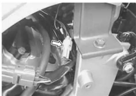
natural_image
Close-up of internal mechanical components with visible wiring and a small connector (no text or symbols)
natural_image
Close-up of electrical connectors and wires with no visible text or symbols
natural_image
Close-up of an electronic component with visible wiring and a white arrow pointing to a component (no text or symbols)SIDE-STAND RELAY INSPECTION
First check the insulation between ① and ② terminals with the tester. Then apply 12 V to terminals ③ and ④ (⊕ to ⑤ and ⊖ to ⑥) and check the continuity between ⑦ and ⑧. If there is no continuity, replace the turn signal/side-stand relay with a new one.

09900-25008: Multi circuit tester set

Tester knob indication: Continuity test (•))
DIODE INSPECTION
Measure the voltage between the terminals using the multi circuit tester. Refer to the following table.
Unit: V
| 1Probe of tester to: | ⊕ Probe of tester to: | ||
| C, B | A | ||
| C, B | More than 1.4 V (Tester's battery voltage) | ||
| A | 0.4 – 0.6 | ||

09900-25008: Multi circuit tester set

Tester knob indication: Diode test ( → )
NOTE:
If the multi circuit tester reads under 1.4 V when the tester probes are not connected, replace its battery.

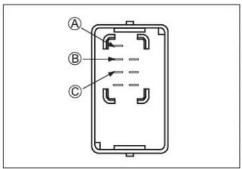

IGNITION SYSTEM

flowchart
graph TD
    A["ECM"] --> B["Power source circuit"]
    B --> C["CPU"]
    C --> D["Throttle position sensor"]
    C --> E["Engine coolant temp. sensor"]
    C --> F["Gear position switch"]
    G["CKP sensor"] --> H["Wave form arrangement circuit"]
    I["Cam position sensor"] --> J["Wave form arrangement circuit"]
    K["Engine stop switch"] --> L["Ignition coil"]
    L --> M["Spark plug #1"]
    L --> N["#2"]
    O["Side-stand relay"] --> P["Fuse"]
    Q["Ignition switch"] --> R["Fuse"]
    S["Battery"] --> T["Battery"]
NOTE:
The fuel cut-off circuit is incorporated in this ECM in order to prevent over-running of engine. When engine speed reaches 9 500 r/min, this circuit cuts off fuel at the fuel injector. But under no load, the clutch lever is pulled or the gear position is neutral, this circuit cuts off fuel when engine speed reaches 9 000 r/min.
CAUTION
Under no load, the engine can run over 9 000 r/min, even if the fuel cut-off circuit is effective, and it may cause engine damage. Do not run the engine without load over 9 000 r/min at anytime.
TROUBLESHOOTING

flowchart
graph TD
    A["No spark or poor spark"] --> B["Check the ignition system couplers for poor connections."]
    B --> C["Correct"]
    C --> D["Continued on next page"]
    E["* Check that the transmission is in neutral and the engine stop switch is in the "RUN" position. Pull the clutch lever. Check that the fuse is not blown and the battery is fully-charged before diagnosing."] --> F["Loose • Poor connection of couplers"]

flowchart
graph TD
    A["Measure the battery voltage between input lead wires (O/W and B/W) at the ECM with the ignition switch in the "ON" position."] --> B{Correct Broken wire harness or poor}
    B --> C["Measure the ignition coil primary peak voltage.(7-19)<br>NOTE: This inspection method is applicable only with the multi circuit tester and the peak volt adaptor."]
    C --> D{Incorrect}
    D --> E["Inspect the ignition coil (-s). (7-20)"]
    E --> F{Correct}
    F --> G["Measure the crankshaft position sensor peak voltage and its resistance.(7-20, -21) Incorrect<br>NOTE: The crankshaft position sensor peak voltage inspection is applicable only with the multi circuit tester and peak volt adaptor."]
    G --> H{Correct}
    H --> I["Inspect the spark plugs. (2-6)"]
    I --> J{Correct Incorrect}
    J --> K{Faulty spark plug (-s)}
    K --> L{Poor connection of the spark plug cap (-s)}
    L --> M{Faulty ignition coil (-s)}
    M --> N{sensor}
    N --> O{Faulty ECM}
    N --> P{Poor connection of ignition couplers.}
    O --> Q["Correct"]
    P --> Q
INSPECTION
IGNITION COIL PRIMARY PEAK VOLTAGE
- Lift and support the fuel tank. (4-51)
- Disconnect the two spark plug caps.
- Connect new two spark plugs to each spark plug cap and ground them.
NOTE:
Make sure that all couplers and spark plugs are connected properly and the battery used is in fully-charged condition.
CAUTION
Avoid grounding the spark plugs and suppling the electrical shock to the cylinder head cover (magnesium parts) in order to prevent the magnesium material from damage.
Measure the No.1 and No.2 ignition coils primary peak voltage in the following procedure.
- Connect the multi circuit tester with peak voltage adaptor as follows.
No.1 ignition coil: + Probe: Black terminal
- Probe: Ground
No.2 ignition coil: ☑ Probe: White/Blue terminal
- Probe: Ground
NOTE:
Do not disconnect the ignition coil primary wire coupler.

09900-25008: Multi circuit tester set
CAUTION
Before using the multi circuit tester and peak volt adaptor, be sure to refer to the appropriate instruction manual.
- Shift the transmission into the neutral and then turn the ignition switch to the "ON" position.
- Pull the clutch lever.
- Press the starter button and allow the engine to crank for a few seconds, and then measure the ignition coil primary peak voltage.
- Repeat the above procedure a few times and measure the highest ignition coil primary peak voltage.

Tester knob indication: Voltage (—)

Ignition coil primary peak voltage: More than 150 V
WARNING
While testing, do not touch the tester probes and spark plugs to prevent receiving an electric shock.
- If the peak voltage is lower than the specified values, inspect the ignition coil. (7-20)

natural_image
Close-up of mechanical components with hoses and tubing, no visible text or symbols


IGNITION COIL RESISTANCE
- Remove the fuel tank. (4-52)
- Disconnect the spark plug caps and coupler.
Measure the ignition coil resistance in both the primary and secondary windings. If the resistance is not within the standard range, replace the ignition coil with a new one.

09900-25008: Multi circuit tester set

Tester knob indication: Resistance (Ω)

Ignition coil resistance
Primary : 2 - 5 Ω ( ⊕ terminal - ⊖ terminal)
Secondary : 24 - 37 kΩ (Plug cap - ⊕ terminal)


natural_image
Technical line drawing of a mechanical component with labeled terminals (no text or symbols beyond basic labels)CKP SENSOR PEAK VOLTAGE
- Remove the seat. (6-4)
- Disconnect the ECM coupler.
NOTE:
Make sure that all of the couplers are connected properly and the battery used is in fully-charged condition.
Measure the CKP sensor peak voltage in the following procedures.
- Connect the multi circuit tester with peak volt adaptor as follows.
⊕ Probe: Yellow/Blue lead wire
- Probe: White lead wire

09900-25008: Multi circuit tester set
CAUTION
Before using the multi circuit tester and peak volt adaptor, be sure to refer to the appropriate instruction manual.
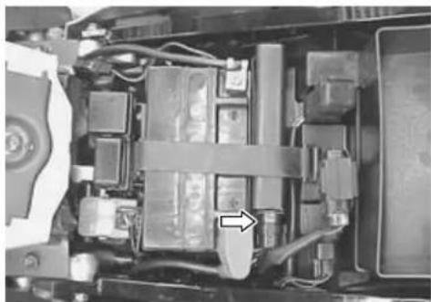
natural_image
Interior view of a vehicle's internal components, showing battery, motors, and wiring (no visible text or symbols)
natural_image
Close-up of a connector with multiple pins and a battery symbol (no readable text or labels)- Shift the transmission into the neutral, and then turn the ignition switch to the "ON" position.
- Pull the clutch lever.
- Press the starter button and allow the engine to crank for a few seconds, and then measure the CKP sensor peak voltage.
- Repeat the above procedure a few times and measure the highest peak voltage.

Tester knob indication: Voltage (---)
DATA
CKP sensor peak voltage: More than 3.7 V
If the peak voltage is lower than the specified values, check the peak voltage at the CKP sensor lead wire coupler.
- Remove the left frame cover. (6-5) - Disconnect the CKP sensor lead wire coupler and connect the multi circuit tester with the peak volt adaptor.
⊕ Probe: Green lead wire
- Probe: Blue lead wire
- Measure the CKP sensor peak voltage at the CKP sensor lead wire coupler in the same manner as on the ECM coupler.

Tester knob indication: Voltage (---)
DATA
CKP sensor peak voltage: More than 3.7 V
If the peak voltage on the CKP sensor lead wire coupler is ok but on the ECM coupler is out of specification, the wire harness must be replaced. If both peak voltages are out of specification, the CKP sensor must be replaced and re-checked.


natural_image
Interior view of a vehicle showing mechanical components and wiring (no visible text or symbols)
CKP SENSOR RESISTANCE
Measure the resistance between the lead wires and ground. If the resistance is not specified value, the CKP sensor must be replaced.

09900-25008: Multi circuit tester set

Tester knob indication: Resistance (Ω)
DATA
CKP sensor resistance: 130 - 240 Ω (Green - Blue)
∞ Ω (Green - Ground)

COMBINATION METER
REMOVAL AND DISASSEMBLY
- Remove the combination meter panel. (6-6).
- Remove the combination meter ①.
CAUTION
When disconnecting and connecting the combination meter coupler, make sure to turn OFF the ignition switch, or electronic parts may get damaged.
• Disassemble the combination meter as follows.
CAUTION
Do not attempt to disassemble the combination meter unit.

natural_image
Mechanical assembly diagram showing internal components with numbered annotations (1 and 2), no readable text or symbols present.
① Combination meter cover
② Combination meter unit
INSPECTION
LED (LIGHT EMITTING DIODE)
Check that the LED lights immediately after turning the ignition switch on.
If the LED fails in operation, replace the combination meter unit with a new one after checking its wire harness/coupler.
STEPPING MOTOR
Check that the pointer calibrates itself immediately after turning the ignition switch on and stops at starting point.
If abnormal condition is found, replace the combination meter unit with a new one after checking its wire harness/coupler.
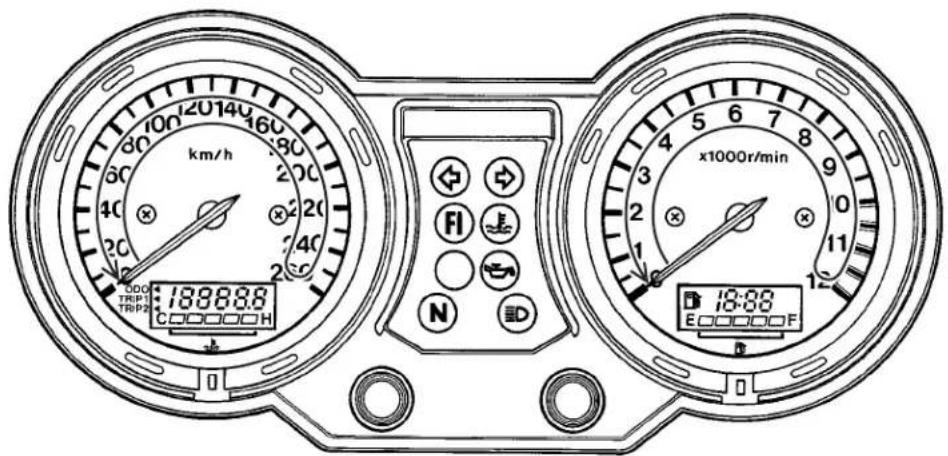
NOTE:
The pointer may not return to the proper position even turning the ignition switch on under low temperature condition. In that case, you can reset the pointer to the proper position by following the instruction below:
1) With the set switch Ⓐ pressed, turn the ignition switch on.
2) Keep pushing the set switch Ⓐ for 3 to 5 seconds.
3) Press the set switch Ⓐ twice (within 1 second). → Reset
* Complete the operation within 10 seconds after the ignition switch has been turned on.

flowchart
graph TD
    A["Time Ignition switch Set switch Ⓐ"] --> B["OFF"]
    B --> C["ON"]
    C --> D["PUSH"]
    D --> E["Release"]
    E --> F["Push"]
    F --> G["Push → Reset"]
    G --> H["10 sec"]

Ⓐ SET SWITCH Ⓑ MODE SWITCH
Pointer will return to the starting point right after the completion of the operation. In the case of the pointer not returning to the proper position after doing above, replace the combination meter unit.
ODOMETER
The odometer indicates “----” when the odometer is faulty. Replace the combination meter unit with a new one.

TRIP METER
The trip meter indicates “----” when the trip meter is faulty. In case the odometer works normally, perform the trip meter reset. If the trip meter isn't restored after above reset, replace the combination meter unit with a new one.

TRIP METER RESET PROCEDURE
- Turn the ignition "ON".
- Select the trip meter by pushing the mode switch Ⓐ.
- Push the set switch Ⓑ for 2 seconds.

ENGINE COOLANT TEMPERATURE METER AND INDICATOR
- Disconnect the engine coolant temperature sensor coupler.
CAUTION
When connecting and disconnecting the engine coolant temp. sensor lead wire coupler, make sure to turn OFF the ignition switch, or electronic parts may get damaged.
- Connect the variable resistor Ⓐ between the terminals.
- Turn the ignition switch "ON".
- Check the display of engine coolant temperature meter as shown below. If any abnormality is found, replace the combination meter with a new one.

natural_image
Close-up of a mechanical component with internal gears and housing (no visible text or symbols)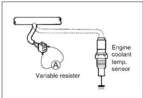
| Water temperature | Under 39 °C | 40 – 59 °C | 60 – 99 °C | 100 – 111 °C |
| Resistance | More than 1.148 kΩ | 1.148 – 0.587 kΩ | 0.587 – 0.188 kΩ | 0.188 – 0.140 kΩ |
| Engine coolant temperature meter | C □□□□□ H | C ■□□□□ H | C ■■□□□ H | C ■■■□□ H |
| Water temperature | 112 – 119 °C | Over 120 °C | Over 122 °C |
| Resistance | 0.140 – 0.116 kΩ | Less than0.116 kΩ | Less than0.111 kΩ |
| Engine coolanttemperature meter | C ▪□□H | C ▪□□□H | ONC ▪□□□H |
- Remove the fuel tank. (4-52)
- Remove the fuel pump. (4-55)
Measure the resistance at each fuel level gauge float position. If the resistance is incorrect, replace the fuel level gauge with a new one.
| Float position Resistance | |
| A“F”(Full) Approx. 4 Ω | |
| B“E”(Empty) | Approx. 182 Ω |

09900-25008: Multi circuit tester set

Tester knob indication: Resistance (Ω)
- Remount the fuel pump. (4-58)

natural_image
Close-up of a hand holding a thin wire attached to a mechanical device with a base (no visible text or symbols)
natural_image
Cross-sectional diagram of a mechanical switch or relay mechanism (no visible text or symbols)
natural_image
Mechanical switch mechanism diagram showing internal components and motion path (no text or labels)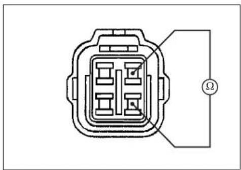
natural_image
Diagram of an electrical connector with a voltage meter and resistor symbol (no text labels)FUEL LEVEL METER
- Lift and support the fuel tank with the fuel tank prop stay. (4-51)
- Connect each resistor between the Yellow/Black and Black/White lead wires at the wire harness.
- Turn the ignition switch "ON" position and wait for approx. 13 seconds.
Check the display of fuel meter as shown below, If any abnormality is found, replace the combination meter with a new one.

natural_image
Close-up of a mechanical component with an arrow pointing to a component (no visible text or symbols)
natural_image
Close-up of a hand holding a small electrical plug with internal circuitry, no visible text or symbols| Resistance | More than 167 Ω | 115 – 167 Ω | 73 – 115 Ω | 45 – 73 Ω 22 | – 45 Ω | Less than 21 Ω |
| Fuel level meter |
OIL PRESSURE INDICATOR
NOTE:
Before inspecting the oil pressure switch, check the engine oil level. (2-13)
- Remove the engine under cover.
- Disconnect the oil pressure switch lead wire from the oil pressure switch.
- Turn the ignition switch "ON" position.
Check if the oil pressure indicator will light, when grounding the lead wire.

natural_image
Close-up of mechanical components with a highlighted section and arrow indicator (no visible text or symbols)
SPEEDOMETER
If the speedometer, odometer or trip meter does not function properly, inspect the speedometer sensor and connection of coupler ①. If the speedometer sensor and connection are all right, replace the meter with a new one.
SPEEDOMETER SENSOR
- Remove the seat. (6-4)
- Remove the fuel tank side covers. (6-5)
- Remove the fuel tank. (4-52)
- Remove the air cleaner box.
- Disconnect speedometer sensor coupler.
- Remove the speedometer sensor ② by removing its mounting bolt.
- Connect 12 V battery, 10 kΩ resistor and the multi circuit tester as shown in the right illustration.
B/R: Black with Red tracer
B/W: Black with White tracer
B: Black

09900-25008: Multi circuit tester set

Tester knob indication: Voltage (---)
- Under above condition, if a suitable screwdriver touching the pick-up surface of the speedometer sensor is moved, the tester reading voltage changes (0 V → 12 V or 12 V → 0 V). If the tester reading voltage does not change, replace the speedometer sensor with a new one.
NOTE:
The highest voltage reading in this test will be the same as that of battery voltage.

natural_image
Close-up of mechanical components with no visible text or symbols
natural_image
Close-up of mechanical components with no visible text or symbols
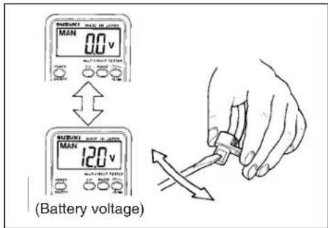
LAMPS
12 V 60/50 W + 5 W (ONLY E02, E19)
HEADLIGHT BEAM ADJUSTMENT
- Adjust the headlight beam, both vertical and horizontal.
Ⓐ: Vertical adjuster
⑧: Horizontal adjuster
NOTE:
To adjust the headlight beam, adjust the beam horizontally first, then adjust the vertically.

natural_image
Mechanical assembly diagram showing a bearing housing with labeled parts (A and B), no readable text or symbols present.RELAYS
TURN SIGNAL/SIDE-STAND RELAY
The turn signal/side-stand relay is composed of the turn signal relay, side-stand relay and diode.

natural_image
Close-up of an automotive battery pack with visible internal components and a white arrow pointing to a component (no text or symbols)INSPECTION
Before removing the turn signal/side-stand relay, check the operation of the turn signal light.
If the turn signal light does not illuminate, inspect the bulb, turn signal switch and circuit connection.
If the bulb, turn signal switch and circuit connection are OK, the turn signal relay may be faulty; therefore, replace the turn signal/ side-stand relay with a new one.
NOTE:
* Make sure that the battery is fully charged.
* Refer to the page 7-16 for the side-stand relay and diode inspection.

STARTER RELAY
7-13
FUEL PUMP RELAY
4-55
SWITCHES
IGNITION SWITCH REMOVAL
- Remove the fuel tank. (4-52)
- Remove the air cleaner box. (4-60)
- Disconnect the ignition switch coupler.
- Remove the ignition switch mounting bolts using the special tools.

09930-11920: Torx bit JT40H
09930-11940: Bit holder
CAUTION
When reusing the ignition switch bolt, clean thread and apply the THREAD LOCK SUPER "1322" or THREAD LOCK "1342".

99000-32050: THREAD LOCK "1342" (USA)

99000-32110: THREAD LOCK SUPER "1322" (Others)

natural_image
Close-up of internal mechanical components with visible wiring and a white arrow pointing to a component (no text or symbols)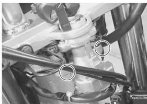
natural_image
Close-up of mechanical components with circular annotations highlighting specific parts (no readable text or symbols)Inspect each switch for continuity with a tester. If any abnormality is found, replace the respective switch assemblies with new ones.
IGNITION SWITCH (For E24)
| Position\Color | R O O/Y B/W | |||
| ON | ||||
| OFF | ||||
| LOCK | ||||
(For Others)
(Except for E03, E24, E28, E33)
PASSING LIGHT SWITCH (Except for E03, E28, E33)
| Position\Color | O/R Y | |
| • | ||
| PUSH | ○— | ○ |
ENGINE STOP SWICH
| Position\Color | O/B O/W | |
| OFF (×) | ||
| RUN (Ω) | ○— | ○ |
STARTER BUTTON
| Position\Color | O/W Y/G | |
| • | ||
| PUSH | ○—○ | |
HORN BUTTON
| Position\Color | B/BI B/W | |
| • | ||
| PUSH | ○— | ○ |
HAZARD (Except for E03, E24, E28, E33)
| Color Position | G/Y Ground | |
| ON (engine is stopped) | ||
| OFF (engine is running) |
(For Others)
| Position\Color | B Ground | |
| ON (engine is stopped) | ||
| OFF (engine is running) |
NOTE:
Before inspecting the oil pressure switch, check the engine oil level. (2-13)
WIRE COLOR
| B : Black | B/W : Black with White tracer |
| Br : Brown | B/Y : Black with Yellow tracer |
| Gr : Gray | B/R : Black with Red tracer |
| Lbl : Light blue | G/Y : Green with Yellow tracer |
| Lg : Light green | O/B : Orange with Black tracer |
| O : Orange | O/BI : Orange with Blue tracer |
| R : Red | O/G : Orange with Green tracer |
| Y : Yellow | O/R : Orange with Red tracer |
| W : White | O/W : Orange with White tracer |
| BI : Blue | O/Y : Orange with Yellow tracer |
| G : Green | W/B : White with Black tracer |
| Y/G : Yellow with Green tracer | |
| Y/W : Yellow with White tracer |
BATTERY SPECIFICATIONS
Type designation FTX14-BS
Capacity 12 V, 43.2 kC (12 Ah)/10 HR
INITIAL CHARGING
Filling electrolyte
- Remove the aluminum tape ① sealing the battery electrolyte filler holes.
NOTE:
When filling electrolyte, the battery must be removed from the vehicle and must be put on the level ground.
- Remove the caps ②.
NOTE:
* After filling the electrolyte completely, use the removed cap ② as the sealed caps of battery-filler holes.
* Do not remove or pierce the sealed areas ③ of the electrolyte container.
- Insert the nozzles of the electrolyte container into the battery's electrolyte filler holes, holding the container firmly so that it does not fall. Take precaution not to allow any of the fluid to spill.
- Make sure air bubbles are coming up each electrolyte container, and leave in this position for about more than 20 minutes.


NOTE:
If no air bubbles are coming up from a filler port, tap the bottom of the electrolyte container two or three times.
Never remove the container from the battery.
• After confirming that the electrolyte has entered the battery completely, remove the electrolyte containers from the battery. Wait for about 20 minutes.
- Insert the caps into the filler holes, pressing in firmly so that the top of the caps do not protrude above the upper surface of the battery's top cover.
CAUTION
* Never use anything except the specified battery.
* Once install the caps to the battery; do not remove the caps.
* Do not tap the caps with a hammer when installing them.


natural_image
Line drawing of a battery with three leads and mounting holes (no text or symbols)
natural_image
Line drawing of a battery with labeled terminals and a central switch (no text or symbols on the diagram itself)- Using multi circuit tester, measure the battery voltage. The tester should indicate more than 12.5 – 12.6 V (DC) as shown in the Fig. If the battery voltage is lower than the specification, charge the battery with a battery charger. (Refer to the recharging operation)
CAUTION
Do not remove the caps on the battery top while charging.

line
| Time (Minutes) | Voltage (V) | | -------------- | ----------- | | 0 | 13 | | 10 | 12.5 |NOTE:
Initial charging for a new battery is recommended if two years have elapsed since the date of manufacture.
SERVICING
Visually inspect the surface of the battery container. If any signs of cracking or electrolyte leakage from the sides of the battery have occurred, replace the battery with a new one. If the battery terminals are found to be coated with rust or an acidic white powdery substance, then this can be cleaned away with sandpaper.
- Using the multi circuit tester, check the battery voltage. If the voltage reading is less than the 12.0 V (DC), recharge the battery with a battery charger.
CAUTION
* When recharging the battery, remove the battery from the motorcycle.
* Do not remove the caps on the battery top while recharging.

line
| Time (Minutes) | Voltage (V) | | -------------- | ----------- | | 0 | 17 | | 10 | 13 | | 20 | 13 | | 30 | 13 | | 40 | 13 | | 50 | 13 | | 60 | 13 |Recharging time: 1.4 A for 5 to 10 hours or 6 A for one hour
CAUTION
Be careful not to permit the charging current to exceed 6 A at any time.
- After recharging, wait for more than 30 minutes and check the battery voltage with a multi circuit tester.
- If the battery voltage is less than the 12.5 V, recharge the battery again.
- If battery voltage is still less than 12.5 V, after recharging, replace the battery with a new one.
- When the motorcycle is not used for a long period, check the battery every 1 month to prevent the battery discharge.
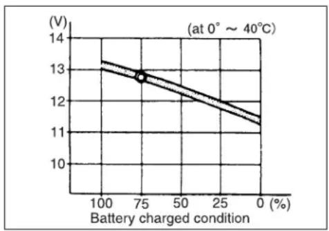
line
(at 0° ~ 40°C) | Battery charged condition (%) | Voltage (V) | | :--- | :--- | | 100 | 13.2 | | 75 | 12.8 | | 25 | 12.0 | | 0 | 11.5 |SERVICING INFORMATION
CONTENTS
TROUBLESHOOTING 8-2
FI SYSTEM MALFUNCTION CODE AND DEFECTIVE
CONDITION 8-2
ENGINE 8-4
RADIATOR (COOLING SYSTEM) 8-9
CHASSIS 8-10
BRAKES 8-11
ELECTRICAL 8-12
BATTERY 8-13
WIRE HARNESS, CABLE AND HOSE ROUTING 8-14
WIRE HARNESS ROUTING 8-14
ENGINE ELECTRICAL PARTS SET-UP 8-17
HIGH-TENSION CORD ROUTING 8-18
THROTTLE CABLE ROUTING 8-19
THROTTLE BODY INSTALLATION/HOSE ROUTING ....8-20
CRANKCASE BREATHER HOSE ROUTING 8-21
CLUTCH HOSE ROUTING 8-22
COOLING SYSTEM HOSE ROUTING 8-23
FRONT BRAKE HOSE ROUTING 8-24
SIDE-STAND SET-UP 8-30
BRAKE PEDAL/FOOTREST SET-UP 8-30
FOOTREST SET-UP 8-31
HANDLEBAR BALANCER INSTALLATION 8-31
SPECIAL TOOLS 8-32
TIGHTENING TORQUE 8-35
ENGINE 8-35
| MALFUNCTION CODE | DETECTED ITEM | DETECTED FAILURE CONDITION CHECK FOR |
| C00 NO FAULT | —— | |
| C11 | Camshaft position sensor | The signal does not reach ECM for more than 3 sec. after receiving the starter signal.The camshaft position sensor wiring and mechanical parts.(Camshaft position sensor, intake cam pin, wiring/coupler connection) |
| C12 | Crankshaft position sensor | The signal does not reach ECM for more than 3 sec. after receiving the starter signal.The crankshaft position sensor wiring and mechanical parts.(Crankshaft position sensor, wiring/coupler connection) |
| C13 | Intake air pressure sensor | The sensor should produce following voltage.(0.10 V sensor voltage < 4.80 V)Without the above range, C13 is indicated.Intake air pressure sensor, wiring/coupler connection. |
| C14 | Throttle position sensor | The sensor should produce following voltage.(0.10 V sensor voltage < 4.80 V)Without the above range, C14 is indicated.Throttle position sensor, wiring/coupler connection. |
| C15 | Engine coolant temperature sensor | The sensor voltage should be the following.(0.10 V sensor voltage < 4.60 V)Without the above range, C15 is indicated.Engine coolant temperature sensor, wiring/coupler connection. |
| C21 | Intake air temperature sensor | The sensor voltage should be the following.(0.10 V sensor voltage < 4.60 V)Without the above range, C21 is indicated.Intake air temperature sensor, wiring/coupler connection. |
| C22 | Atmospheric pressure sensor | The sensor voltage should be the following.(0.10 V sensor voltage < 4.80 V)Without the above range, C22 is indicated.Atm. pressure sensor, wiring/coupler connection. |
| C23 | Tip over sensor The sensor voltage should be less than the following for more than 4 sec. after ignition switch turns ON.(0.20 V sensor voltage < 4.60 V)Without the above value, C23 is indicated.Tip over sensor, wiring/coupler connection. | |
| C24 or C25 | Ignition signal Crankshaft position sensor (pick-up coil) signal is produced but signal from ignition coil is interrupted continuous by two times or more. In this case, the code C24 or C25 is indicated.Ignition coil, wiring/coupler connection, power supply from the battery. | |
| C28 | Secondary throttle valve actuator | When no actuator control signal is supplied from the ECM or communication signal does not reach ECM or operation voltage does not reach STVA motor, C28 is indicated. STVA can not operate.STVA lead wire/coupler. |
| C29 | Secondary throttle position sensor | The sensor should produce following voltage.(0.10 V ≤ sensor voltage < 4.80 V)Without the above range, C29 is indicated.Secondary throttle position sensor, wiring/coupler connection. |
| C31 | Gear position signal Gear position signal voltage should be higher than the following for more than 4 seconds.(Gear position switch voltage > 1.0 V)Without the above value, C31 is indicated.Gear position sensor, wiring/coupler connection. Gearshift cam etc. | |
| C32 or C33 | Fuel injector signal When fuel injection signal stops, the C32 or C33 is indicated.J Injector, wiring/coupler connection, power supply to the injector. | |
| C41 | Fuel pump relay signal When no signal is supplied from fuel pump relay, C41 is indicated.Fuel pump relay, connecting lead, power source to fuel pump relay. | |
| C42 | Ignition switch signal Ignition switch signal is not input in the ECM.Ignition switch, lead wire/coupler. | |
| C44 | Heated oxygen sensor (HO2S) | The sensor voltage should be less than the following after warming up condition.(Sensor voltage < 0.4 V)Without the above value, C44 is indicated.Heater operation voltage does not reach in the oxygen heater circuit, C44 in indicated.The Heater can not operate.HO2S lead wire/coupler connection.Battery voltage supply to the HO2S. |
ENGINE
| Complaint Symptom and possible causes Remedy | ||
| Engine will not start or is hard to start. | Compression too low1. Tappet clearance out of adjustment.2. Worn valve guides or poor seating of valves.3. Mistimed valves.4. Excessively worn piston rings.5. Worn-down cylinder bores.6. Starter motor cranks too slowly.7. Poor seating of spark plugs.Plugs not sparking1. Fouled spark plugs.2. Wet spark plugs.3. Defective ignition coil or camshaft position sensor.4. Open or short in high-tension cords.5. Defective crankshaft position sensor.6. Defective ECM.7. Open-circuited wiring connections.No fuel reaching the intake manifold1. Clogged fuel filter or fuel hose.2. Defective fuel pump.3. Defective fuel pressure regulator.4. Defective fuel injector.5. Defective fuel pump relay.6. Defective ECM.7. Open-circuited wiring connections.Incorrect fuel/air mixture1. Throttle position sensor out of adjustment.2. Defective fuel pump.3. Defective fuel pressure regulator.4. Defective throttle position sensor.5. Defective crankshaft position sensor.6. Defective intake air pressure sensor.7. Defective atmospheric pressure sensor.8. Defective ECM.9. Defective engine coolant temp. sensor.10. Defective intake air temp. sensor. | Adjust.Repair or replace.Adjust.Replace.Replace.Replace.See electrical section.Retighten.Clean.Clean and dry.Replace.Replace.Replace.Replace.Replace.Replace indicates or replace.Clean or replace.Replace.Replace.Replace.Replace.Replace.Check and repair.Adjust.Replace.Replace.Replace.Replace.Replace.Replace.Replace.Replace. |
| Engine idles poorly. | 1. Tappet clearance out of adjustment.2. Poor seating of valves.3. Defective valve guides.4. Worn down camshaft.5. Too wide spark plug gaps.6. Defective ignition coil.7. Defective crankshaft position sensor.8. Defective ECM.9. Defective throttle position sensor.10. Defective fuel pump.11. Imbalanced throttle valve.12. Damaged or cracked vacuum hose. | Adjust.Replace or repair.Replace.Replace.Replace.Replace.Replace.Replace.Replace. |
| Engine stalls often Incorrect fuel/air mixture | ||
| 1. Defective intake air pressure sensor or circuit. | Repair or replace. | |
| 2. Clogged fuel filter. | Clean or replace. | |
| 3. Defective fuel pump. | Replace. | |
| 4. Defective fuel pressure regulator. | Replace. | |
| 5. Damaged or cracked vacuum hose. | Replace. | |
| 6. Defective engine coolant temp. sensor. | Replace. | |
| 7. Defective thermostat. | Replace. | |
| 8. Defective intake air temp. sensor. | Replace. | |
| Fuel injector improperly operating | ||
| 1. Defective fuel injector. | Replace. | |
| 2. No injection signal from ECM. | Repair or replace. | |
| 3. Open or short circuited wiring connection. | Repair or replace. | |
| 4. Defective battery or low battery voltage. | Replace or recharge. | |
| Control circuit or sensor improperly operating | ||
| 1. Defective ECM. | Replace. | |
| 2. Defective fuel pressure regulator. | Replace. | |
| 3. Defective throttle position sensor. | Replace. | |
| 4. Defective intake air temp. sensor. | Replace. | |
| 5. Defective camshaft position sensor. | Replace. | |
| 6. Defective crankshaft position sensor. | Replace. | |
| 7. Defective engine coolant temp. sensor. | Replace. | |
| 8. Defective fuel pump relay. | Replace. | |
| Engine internal parts improperly operating | ||
| 1. Fouled spark plugs. | Clean. | |
| 2. Defective crankshaft position sensor or ECM. | Replace. | |
| 3. Clogged fuel hose. | Clean. | |
| 4. Tappet clearance out of adjustment. | Adjust. | |
| Noisy engine. Excessive valve chatter | ||
| 1. Too large tappet clearance.2. Weakened or broken valve springs.3. Worn tappet or cam surface.4. Worn and burnt camshaft journal. | Adjust.Replace.Replace.Replace. | |
| Noise seems to come from piston1. Worn down pistons or cylinders.2. Combustion chambers fouled with carbon.3. Worn piston pins or piston pin bore.4. Worn piston rings or ring grooves. | Replace.Clean.Replace.Replace. | |
| Noise seems to come from timing chain1. Stretched chain.2. Worn sprockets.3. Tension adjuster not working. | Replace.Replace.Replace变换 or replace. | |
| Noise seems to come from clutch1. Worn splines of countershaft or hub.2. Worn teeth of clutch plates.3. Distorted clutch plates, driven and drive.4. Worn clutch release bearing.5. Weakened clutch dampers. | Replace.Replace.Replace.Replace.Replace the primary driven gear. | |
| Noise seems to come from crankshaft1. Rattling bearings due to wear.2. Worn and burnt big-end bearings.3. Worn and burnt journal bearings.4. Too large thrust clearance. | Replace.Replace.Replace.Replace thrust bearing. | |
| Noise seems to come from transmission1. Worn or rubbing gears.2. Worn splines.3. Worn or rubbing primary gears.4. Worn bearings. | Replace.Replace.Replace.Replace. | |
| Noise seems to come from water pump1. Too much play on pump shaft bearing.2. Worn or damaged impeller shaft.3. Worn or damaged mechanical seal.4. Contact between pump case and impeller. | Replace.Replace.Replace.Replace. | |
| Engine runs poorly in high speed range. | Defective engine internal/electrical parts1. Weakened valve springs.2. Worn camshafts.3. Valve timing out of adjustment.4. Too narrow spark plug gaps.5. Ignition not advanced sufficiently due to poorly working timing advance circuit.6. Defective ignition coil.7. Defective crankshaft position sensor.8. Defective ECM.9. Clogged air cleaner element.10. Clogged fuel hose, resulting in inadequate fuel supply to injector.11. Defective fuel pump.12. Defective throttle position sensor.13. Defective secondary throttle position sensor or its actuator. | Replace.Replace.Replace.Replace.ECM.Replace.Replace.Replace.Clean indicates and prime.Replace.Replace.Replace. |
| Engine runs poorly in high speed range. | Defective air flow system1. Clogged air cleaner element.2. Defective throttle valve.3. Defective secondary throttle valve.4. Sucking air from throttle body joint.5. Defective ECM.6. Imbalanced throttle valve synchronization.Defective control circuit or sensor1. Low fuel pressure.2. Defective throttle position sensor.3. Defective intake air temp. sensor.4. Defective camshaft position sensor.5. Defective crankshaft position sensor.6. Defective gear position switch.7. Defective intake air pressure sensor.8. Defective atmospheric pressure sensor.9. Defective ECM.10. Throttle position sensor out of adjustment.11. Defective secondary throttle position sensor and/or secondary throttle valve actuator. | Clean or replace.Adjust or replace.Adjust or replace.Repair or replace.Replace.Adjust.Repair or replace.Replace.Replace.Replace.Replace.Replace.Replace.Replace.Replace.Replace. |
| Engine lacks power. | Defective engine internal/electrical parts1. Loss of tappet clearance.2. Weakened valve springs.3. Valve timing out of adjustment.4. Worn piston rings or cylinders.5. Poor seating of valves.6. Fouled spark plug.7. Incorrect spark plug.8. Clogged injector.9. Throttle position sensor out of adjustment.10. Clogged air cleaner element.11. Imbalanced throttle valve synchronization.12. Sucking air from throttle valve or vacuum hose.13. Too much engine oil.14. Defective fuel pump or ECM.15. Defective crankshaft position sensor and ignition coil.Defective control circuit or sensor1. Low fuel pressure.2. Defective throttle position sensor.3. Defective intake air temp. sensor.4. Defective camshaft position sensor.5. Defective crankshaft position sensor.6. Defective gear position switch.7. Defective intake air pressure sensor.8. Defective atmospheric pressure sensor.9. Defective ECM.10. Imbalanced throttle valve synchronization.11. Throttle position sensor out of adjustment.12. Defective secondary throttle position sensor and/or secondary throttle valve actuator. | Adjust.Replace.Replace.Replace.Repair.Clean or replace.Adjust or replace.Clean.Adjust.Clean.Adjust.Retighten or replace.Drain out excess oil.Replace.Replace.Repair or replace.Replace.Replace.Replace.Replace.Replace.Replace.Replace. |
| Engine overheats. Defective engine internal parts | ||
| 1. Heavy carbon deposit on piston crowns.2. Not enough oil in the engine.3. Defective oil pump or clogged oil circuit.4. Sucking air from intake pipes.5. Use of incorrect engine oil.6. Defective cooling system.Lean fuel/air mixture1. Short-circuited intake air pressure sensor/lead wire.2. Short-circuited intake air temp. sensor/lead wire.3. Sucking air from intake pipe joint.4. Defective fuel injector.5. Defective engine coolant temp. sensor.The other factors1. Ignition timing too advanced due to defective timing advance system (engine coolant temp. sensor, gear position switch, crankshaft position sensor and ECM.)2. Drive chain too tight. | Clean.Add oil.Replace or clean.Retighten or replace.Change.See radiator section.Repair or replace.Repair or replace.Repair or replace.Replace.Replace.Replace.Replace.Adjust. | |
| Dirty or heavy exhaust smoke. | 1. Too much engine oil in the engine.2. Worn piston rings or cylinders.3. Worn valve guides.4. Scored or scuffed cylinder walls.5. Worn valves stems.6. Defective stem seal.7. Worn oil ring side rails. | Check with inspection window.Drain excess oil.Replace.Replace.Replace.Replace.Replace.Replace.Replace. |
| Slipping clutch. | 1. Weakened clutch springs.2. Worn or distorted pressure plate.3. Distorted clutch plates or clutch plate. | Replace.Replace.Replace. |
| Dragging clutch. | 1. Some clutch spring weakened while others are not.2. Distorted pressure plate or clutch plate. | Replace.Replace. |
| Transmission will not shift. | 1. Broken gearshift cam.2. Distorted gearshift forks.3. Worn gearshift pawl. | Replace.Replace.Replace. |
| Transmission will not shift back. | 1. Broken return spring on shift shaft.2. Rubbing or sticky shift shaft.3. Distorted or worn gearshift forks. | Replace.Repair or replace.Replace. |
| Transmission jumps out of gear. | 1. Worn shifting gears on driveshaft or countershaft.2. Distorted or worn gearshift forks.3. Weakened stopper spring on gearshift stopper. | Replace.Replace.Replace. |
RADIATOR (COOLING SYSTEM)
| Complaint Symptom and possible causes Remedy | ||
| Engine overheats. | 1. Not enough engine coolant.2. Radiator core clogged with dirt or scale.3. Faulty cooling fan.4. Defective cooling fan thermo-switch.5. Clogged water passage.6. Air trapped in the cooling circuit.7. Defective water pump.8. Use of incorrect engine coolant.9. Defective thermostat. | Add engine coolant.Clean.Repair or replace.Replace.Clean.Bleed air.Replace.Replace.Replace. |
| Engine overcools. 1. Defective cooling fan thermo-switch.2. Extremely cold weather.3. Defective thermostat. | Replace.Put on radiator cover.Replace. | |
CHASSIS
| Complaint Symptom and possible causes Remedy | ||
| Heavy steering. | 1. Overtightened steering stem nut.2. Broken bearing in steering stem.3. Distorted steering stem.4. Not enough pressure in tires. | Adjust.Replace.Replace. Adjust. |
| Wobbly handlebars. 1. | Loss of balance between right and left front forks.2. Distorted front fork.3. Distorted front axle or crooked tire.4. Loose steering stem nut.5. Worn or incorrect tire or wrong tire pressure.6. Worn bearing/race in steering stem. | Replace.Repair or replace.Replace. Adjust. Adjust or replace.Replace. |
| Wobbly front wheel. | 1. Distorted wheel rim.2. Worn front wheel bearings.3. Defective or incorrect tire.4. Loose axle or axle pinch bolt.5. Incorrect front fork oil level. | Replace.Replace. Replace.Retighten.Adjust. |
| Front suspension too soft. | 1. Weakened springs.2. Not enough fork oil.3. Wrong viscous fork oil.4. Improperly set front fork spring adjuster.5. Improperly set front fork damping force adjuster. | Replace.Replenish.Replace.Adjust.Adjust. |
| Front suspension too stiff. | 1. Too viscous fork oil.2. Too much fork oil.3. Improperly set front fork spring adjuster.4. Improperly set front fork damping force adjuster.5. Bent front axle. | Replace.Drain excess oil.Adjust.Adjust.Replace. |
| Noisy front suspension. | 1. Not enough fork oil.2. Loose bolts on suspension. | Replenish.Retighten. |
| Wobbly rear wheel. | 1. Distorted wheel rim.2. Worn rear wheel bearing or swingarm bearings.3. Defective or incorrect tire.4. Worn swingarm and rear suspensions.5. Loose nuts or bolts on rear suspensions. | Replace.Replace.Replace.Replace.Retighten. |
| Rear suspension too soft. | 1. Weakened spring of shock absorber.2. Leakage of oil from shock absorber.3. Improperly set rear spring unit adjuster.4. Improperly set damping force adjuster. | Replace.Replace.Adjust.Adjust. |
| Rear suspension too stiff. | 1. Bent shock absorber shaft.2. Bent swingarm pivot shaft.3. Worn swingarm and suspension bearings.4. Improperly set rear suspension adjuster.5. Improperly set damping force adjuster. | Replace.Replace.Replace.Adjust.Adjust. |
| Noisy rear suspension. | 1. Loose nuts or bolts on rear suspension.2. Worn swingarm and suspension bearings. | Retighten.Replace. |
BRAKES
| Complaint Symptom and possible causes Remedy | ||
| Insufficient brake power. | 1. Leakage of brake fluid from hydraulic system.2. Worn pads.3. Oil adhesion on friction surface of pads/shoe.4. Worn disc.5. Air in hydraulic system.6. Not enough brake fluid in the reservoir. | Repair or replace.Replace.Clean disc and pads.Replace.Bleed air.Replenish. |
| Brake squeaking. 1. Carbon adhesion on pad surface.2. Tilted pad.3. Damaged wheel bearing.4. Loose front-wheel axle or rear-wheel axle.5. Worn pads or disc.6. Foreign material in brake fluid.7. Clogged return port of master cylinder. | Repair surface with sandpaper.Correct pad fitting or replace.Replace.Tighten to specified torque.Replace.Replace brake fluid.Disassemble and clean master cylinder. | |
| Excessive brake lever stroke. | 1. Air in hydraulic system.2. Insufficient brake fluid.3. Improper quality of brake fluid. | Bleed air.Replenish fluid to specified level; bleed air.Replace with correct fluid. |
| Leakage of brake fluid. | 1. Insufficient tightening of connection joints.2. Cracked hose.3. Worn piston and/or cup. | Tighten to specified torque.Replace.Replace piston and/or cup. |
| Brake drags. | 1. Rusty part.2. Insufficient brake lever or brake pedal pivot lubrication. | Clean and lubricate.Lubricate. |
ELECTRICAL
| Complaint Symptom and possible causes Remedy | ||
| No sparking or poor sparking. | 1. Defective ignition coil or camshaft position sensor.2. Defective spark plugs.3. Defective crankshaft position sensor.4. Defective ECM.5. Defective tip over sensor.6. Open-circuited wiring connections. | Replace.Replace.Replace.Replace.Replace.Replace.Check and repair. |
| Spark plugs soon become fouled with carbon. | 1. Mixture too rich.2. Idling speed set too high.3. Incorrect gasoline.4. Dirty air cleaner element.5. Too cold spark plugs. | Consult FI system.Adjust fast idle or throttle stop screw.Change.Clean or replace.Replace with hot type plugs. |
| Spark plugs become fouled too soon. | 1. Worn piston rings.2. Worn piston or cylinders.3. Excessive clearance of valve stems in valve guides.4. Worn stem oil seal. | Replace.Replace.Replace.Replace. |
| Spark plug electrodes overheat or burn. | 1. Too hot spark plugs.2. Overheated the engine.3. Loose spark plugs.4. Too lean mixture. | Replace with cold type plugs.Tune up.Retighten.Consult FI system. |
| Generator does not charge. | 1. Open- or short-circuited lead wires, or loose lead connections.2. Short-circuited, grounded or open generator coils.3. Short-circuited or punctured regulator/rectifiers. | Repair or replace or retighten.Replace.Replace. |
| Generator does charge, but charging rate is below the specification. | 1. Lead wires tend to get short- or open-circuited or loosely connected at terminals.2. Grounded or open-circuited stator coils or generator.3. Defective regulator/rectifier.4. Defective cell plates in the battery. | Repair or retighten.Replace.Replace.Replace the battery. |
| Generator over-charges. | 1. Internal short-circuit in the battery.2. Damaged or defective resistor element in the regulator/ rectifier.3. Poorly grounded regulator/rectifier. | Replace indicates all ground connection. |
| Unstable charging. | 1. Lead wire insulation frayed due to vibration, resulting in intermittent short-circuiting.2. Internally short-circuited generator.3. Defective regulator/rectifier. | Repair or replace.Replace.Replace. |
| Starter button is not effective. | 1. Run down battery.2. Defective switch contacts.3. Brushes not seating properly on starter motor commutator.4. Defective starter relay/starter interlock switch.5. Defective main fuse. | Repair or replace.Replace.Replace.Replace. |
BATTERY
| Complaint Symptom and possible causes Remedy | ||
| “Sulfation”, acidic white powdery substance or spots on surfaces of cell plates. | 1. Cracked battery case.2. Battery has been left in a run-down condition for a long time. | Replace the battery.Replace the battery. |
| Battery runs down quickly. | 1. Trouble in charging system.2. Cell plates have lost much of their active material as a result of overcharging.3. Internal short-circuit in the battery.4. Too low battery voltage.5. Too old battery. | Check the generator, regulator/rectifier and circuit connections and make necessary adjustments to obtain specified charging operation.Replace the battery, and correct the charging system.Replace the battery.Recharge the battery fully.Replace the battery. |
| Battery “sulfation”. | 1. Incorrect charging rate.(When not in use battery should be checked at least once a month to avoid sulfation.)2. The battery was left unused in a cold climate for too long. | Replace the battery.Replace the battery if badly sulfated. |
WIRE HARNESS, CABLE AND HOSE ROUTING WIRE HARNESS ROUTING

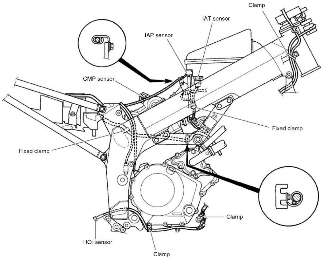


ENGINE ELECTRICAL PARTS SET-UP

HIGH-TENSION CORD ROUTING

THROTTLE CABLE ROUTING

THROTTLE BODY INSTALLATION/HOSE ROUTING

CRANKCASE BREATHER HOSE ROUTING

CLUTCH HOSE ROUTING

COOLING SYSTEM HOSE ROUTING

REAR BRAKE HOSE ROUTING
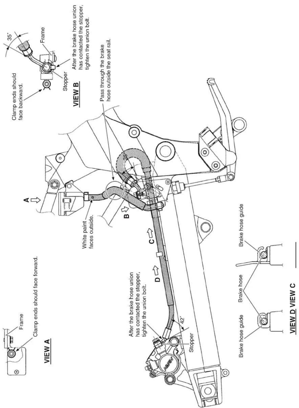
FUEL TANK DRAIN HOSE ROUTING
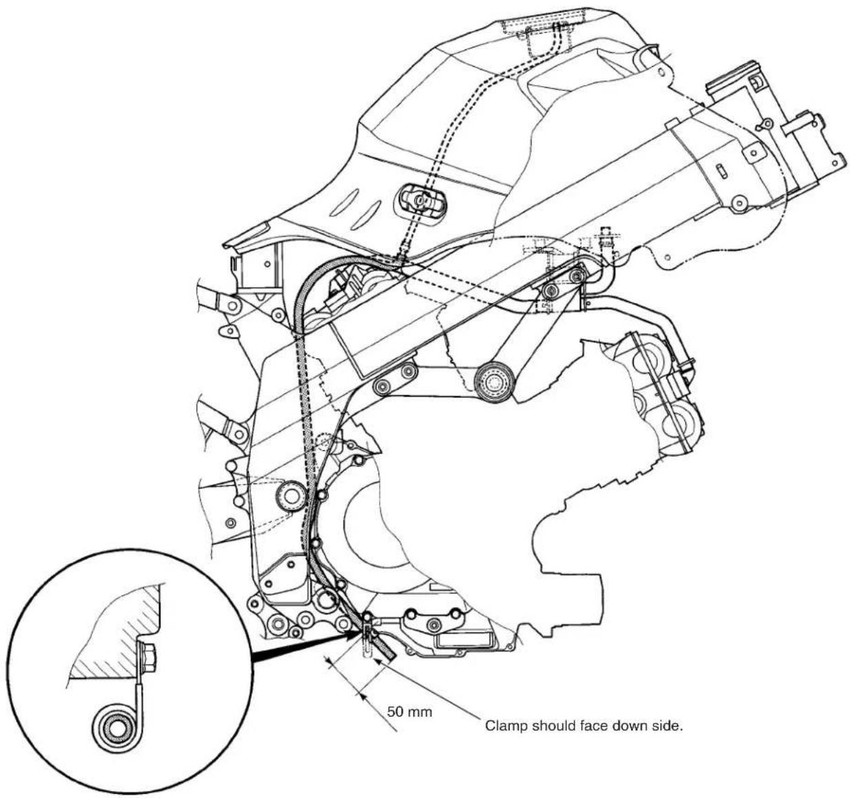
FUEL TANK INSTALLATION

PAIR (AIR SUPPLY) SYSTEM HOSE ROUTING

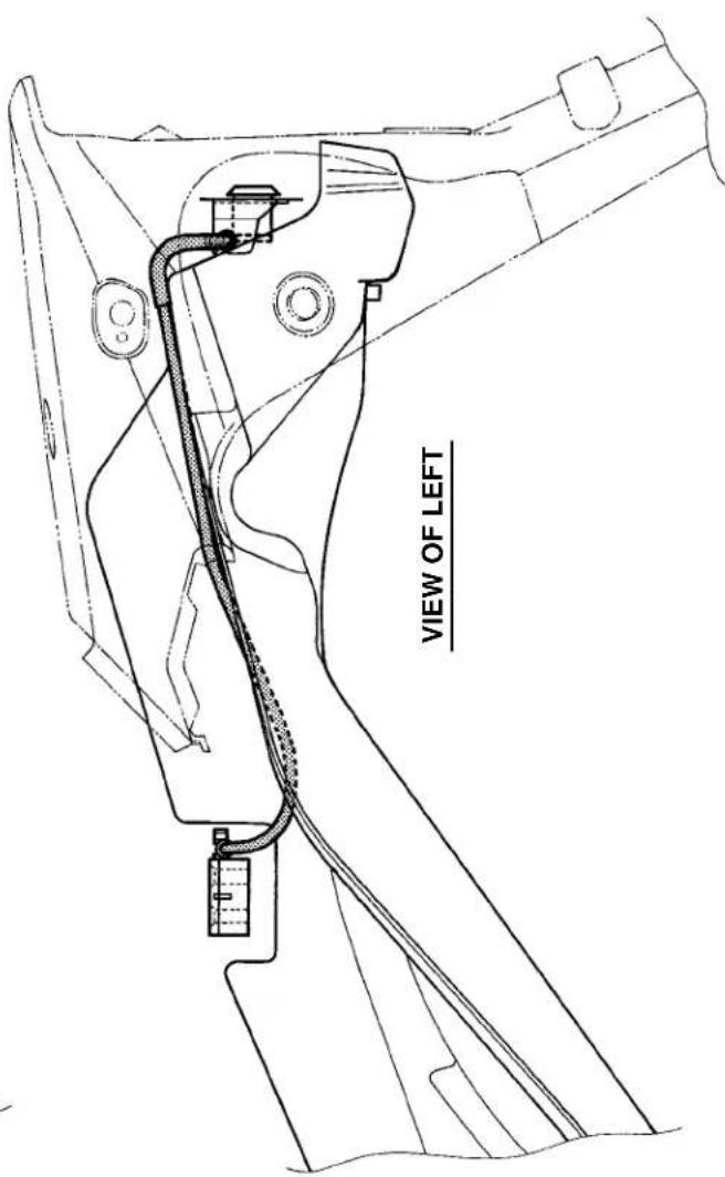
SIDE-STAND SET-UP

BRAKE PEDAL/FOOTREST SET-UP

FOOTREST SET-UP
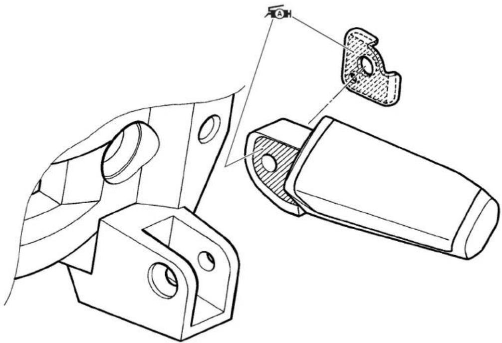
natural_image
Technical line drawing of a mechanical bracket assembly (no text or symbols)HANDLEBAR BALANCER INSTALLATION

LH clearance Ⓐ is 0 mm.
RH clearance Ⓐ is 0.5 – 1.5 mm.
NOTE:
After installing the RH balancer weight, check that throttle grip rotate smoothly by turning it.
SPECIAL TOOLS
 09900-06107Snap ring pliers 09900-06107Snap ring pliers | 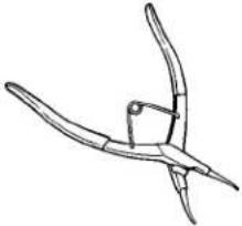 09900-06108Snap ring pliers 09900-06108Snap ring pliers | 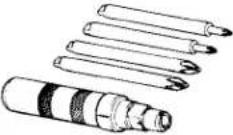 09900-09004Impact driver set 09900-09004Impact driver set | 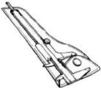 09900-20101 or09900-20102Vernier calipers 09900-20101 or09900-20102Vernier calipers | 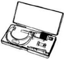 09900-20202Micrometer(25 – 50 mm) 09900-20202Micrometer(25 – 50 mm) |
 09900-20204Micrometer(75 – 100 mm) 09900-20204Micrometer(75 – 100 mm) |  09900-20205Micrometer(0 – 25 mm) 09900-20205Micrometer(0 – 25 mm) | 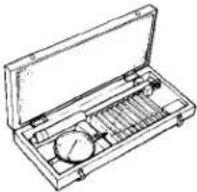 09900-20508Cylinder gauge set 09900-20508Cylinder gauge set |  09900-20602Dial gauge(1/1000 mm, 1 mm) 09900-20602Dial gauge(1/1000 mm, 1 mm) |  09900-20607Dial gauge(1/100 mm, 10 mm) 09900-20607Dial gauge(1/100 mm, 10 mm) |
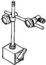 09900-20701Magnetic stand 09900-20701Magnetic stand |  09900-2080309900-20806Thickness gauge 09900-2080309900-20806Thickness gauge |  09900-20805Tire depth gauge 09900-20805Tire depth gauge |  09900-21304V-block (100 mm) 09900-21304V-block (100 mm) |  09900-2230109900-22302Plastigauge 09900-2230109900-22302Plastigauge |
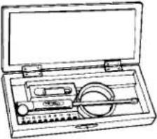 09900-22403Small bore gauge(18 – 35 mm) 09900-22403Small bore gauge(18 – 35 mm) | 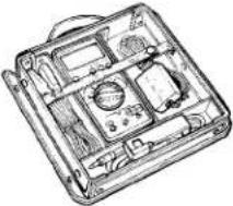 09900-25008Multi circuit testerset 09900-25008Multi circuit testerset |  09913-10750Compression gaugeadapter 09913-10750Compression gaugeadapter |  09913-13121Carburetor balancerset 09913-13121Carburetor balancerset |  09913-50121Oil seal remover 09913-50121Oil seal remover |
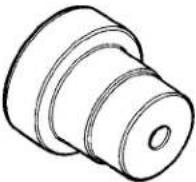 09913-60230Journal bearingremover/installer 09913-60230Journal bearingremover/installer |  09913-60240Journal bearingholder 09913-60240Journal bearingholder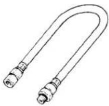 |  09913-70210Bearing installer set 09913-70210Bearing installer set | 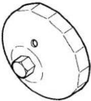 09915-40610Oil filter wrench 09915-40610Oil filter wrench |  09915-64510Compression gauge 09915-64510Compression gauge |
| 09915-72410Oil pressure gauge attachment | 09915-74521Oil pressure gauge hose | 09915-74532Oil pressure gauge adaptor | 09915-77331Meter (for high pres-sure) | 09916-10911Valve lapper set |
 |  | 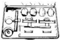 |  |  |
| 09916-14510Valve spring com-pressor | 09916-14910Valve spring com-pressor attachment | 09916-21111Valve seat cutter set | 09916-24480Solid pilot(N-140-5.5) | Valve seat cutter headSee page 3-42. |
 |  |  |  |  |
| 09916-34542Reamer handle | 09916-34550Valve guide reamer(5.5 mm) | 09916-34580Valve guide reamer(10.8 mm) | 09916-44910Valve guide remover/installer | 09916-53340Attachment |
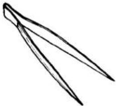 |  |  |  |  |
| 09916-84511Tweezers | 09917-47010Vacuum pump gauge | 09920-13120Crankcase separat-ing tool | 09920-53740Clutch sleeve hub holder | 09921-20240Bearing remover set |
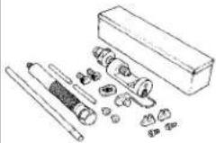 |  |  |  |  |
| 09922-22711Drive chain cutting and joining tool | 09923-73210Bearing remover | 09923-74511Bearing puller | 09924-74570Final drive gear bearing installer/ remover | 09924-84510Bearing installer set |
| 09924-84521 Bearing installer set | 09925-18011 Steering bearing installer | 09930-11920 Torx bit JT40H | 09930-11940 Bit holder | 09930-11950 Torx wrench |
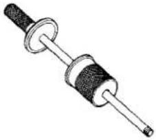 |  | 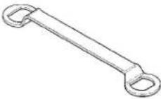 |  |  |
| 09930-30102 Sliding shaft | 09930-30450 Rotor remover | 09930-44541 Rotor holder | 09930-73110 Starter torque limiter holder | 09930-73120 Starter torque limiter socket |
 | 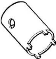 | 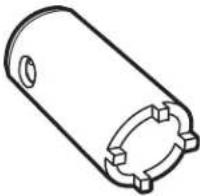 |  |  |
| 09930-82710 Mode selection switch | 09940-14911 Steering stem nut wrench | 09940-14940 Swingarm pivot thrust adjuster socket wrench | 09940-14960 Steering nut wrench socket | 09940-14990 Engine mounting thrust adjuster socket wrench |
 | 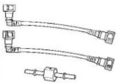 |  |  |  |
| 09940-40211 Fuel pressure gauge adapter | 09940-40220 Fuel pressure gauge hose attachment | 09940-52841 Front fork inner rod holder | 09940-52861 Front fork oil seal installer | 099340-92720 Spring scale |
 |  |  |  | |
| 09941-34513 Steering race installer | 09941-54911 Bearing outer race remover | 09943-74111 Fork oil level gauge | 09944-28320 HEXAGON BIT |
NOTE:
When ordering a special tool, please confirm whether it is available or not.
TIGHTENING TORQUE ENGINE
| ITEM N·m kgf·m lb·ft | ||||
| Cylinder head cover bolt 14 1.4 10.0 | ||||
| Spark plug 11 1.1 8.0 | ||||
| Camshaft journal holder bolt 10 1.0 7.0 | ||||
| Cam chain tension adjuster bolt [F] 23 2.3 16.5 | ||||
| [R] 7 0.7 5.0 | ||||
| Cam chain tension adjuster mounting bolt 10 1.0 7.0 | ||||
| Cam drive idle gear/sprocket shaft | 40 4.0 29.0 | |||
| Cam chain tensioner mounting bolt | 10 1.0 7.0 | |||
| Cylinder head nut | [M: 8] | 25 2.5 18.0 | ||
| [M: 6] | 10 | 1.0 | 7.0 | |
| Cylinder head bolt | [M: 10] | 47 4.7 34.0 | ||
| [M: 6] | 10 | 1.0 | 7.0 | |
| Cylinder nut | [M: 6] | 10 | 1.0 7.0 | |
| Water drain bolt | [M: 6] | 5.5 0.55 | 4.0 | |
| [M: 8] | 13 | 1.3 | 9.5 | |
| Clutch sleeve hub nut | 150 | 15.0 | 108.5 | |
| Clutch spring set bolt | 10 1.0 | 7.0 | ||
| Cam drive idle gear/sprocket nut | 70 7.0 50.5 | |||
| Primary drive gear nut | 115 | 11.5 | 83.0 | |
| Generator cover plug | 15 1.5 11.0 | |||
| Valve timing inspection plug | 23 | 2.3 | 16.5 | |
| Generator rotor bolt | 160 | 16.0 | 115.5 | |
| Starter clutch bolt | 26 2.6 19.0 | |||
| Generator stator set bolt | 10 1.0 7.0 | |||
| Gearshift cam stopper bolt | 10 1.0 7.0 | |||
| Gearshift cam stopper plate bolt | 10 1.0 7.0 | |||
| Gearshift arm stopper bolt | 23 2.3 16.5 | |||
| Oil pressure switch | 14 1.4 | 10.0 | ||
| Crankcase bolt | [M: 6] | 11 | 1.1 | 8.0 |
| [M: 8] | 26 | 2.6 | 19.0 | |
| Generator cover bolt | [M: 6] | 11 | 1.1 | 8.0 |
| Clutch cover bolt | [M: 6] | 11 | 1.1 8.0 | |
| Gearshift cover bolt | [M: 6] | 11 | 1.1 8.0 | |
| Water pump case bolt | [M: 6] | 11 | 1.1 | 8.0 |
| Oil gallery plug | [M: 16] | 35 | 3.5 | 25.5 |
| [M: 8] | 18 | 1.8 | 13.0 | |
| Oil drain plug | 23 2.3 16.5 | |||
| Piston cooling oil nozzle screw | 8 0.8 6.0 | |||
| Oil pump mounting bolt | 10 1.0 7.0 | |||
| Conrod bearing cap bolt | (Initial) | 35 3.5 25.5 | ||
| (Final) | After tightening to the above torque, tighten 1/4 of a turn (90°). | |||
| ITEM N·m kgf-m lb-ft | ||||
| Exhaust pipe bolt 23 2.3 16.5 | ||||
| Muffler mounting bolt/nut 23 2.3 16.5 | ||||
| Oil cooler union bolt 23 2.3 16.5 | ||||
| Engine sprocket nut 115 11.5 83.0 | ||||
| Engine mounting pinch bolt 23 2.3 16.5 | ||||
| Engine mounting bolt/nut [M: 12] 75 7.5 54.0[M: 10] 55 5.5 40.0 | ||||
| Engine mounting thrust adjuster | 12 1.2 | 8.5 | ||
| Engine mounting thrust adjuster lock nut | 45 4.5 32.5 | |||
| Engine mounting bracket pinch bolt | 23 2.3 16.5 | |||
| Engine mounting bracket bolt | 23 2.3 16.5 | |||
| Cooling fan thermo-switch | 18 1.8 13.0 | |||
FI SYSTEM PARTS
| ITEM N·m kgf-m lb-ft | |||
| Speed sensor rotor bolt | 23 2.3 16.5 | ||
| ECTS | 18 1.8 13.0 | ||
| IATS | 18 1.8 13.0 | ||
| CMPS mounting bolt | 8 | 0.8 | 5.7 |
| Fuel delivery pipe mounting screw | 5 | 0.5 | 3.7 |
| Fuel pump mounting bolt 10 1.0 7.3 | |||
| Throttle body connecting bolt | 5 | 0.5 | 3.7 |
| Actuator motor cover nut | 2 | 0.2 | 1.5 |
| TPS and STPS mounting screw | 3.5 0.35 2.5 | ||
CHASSIS
| ITEM N·m kgf-m lb-ft | |||
| Steering stem head nut 90 9.0 65.0 | |||
| Steering stem lock nut 80 8.0 58.0 | |||
| Front fork upper clamp bolt 23 2.3 16.5 | |||
| Front fork lower clamp bolt 23 2.3 16.5 | |||
| Front fork cap bolt 23 2.3 16.5 | |||
| Front fork inner rod lock nut 20 2.0 14.5 | |||
| Front fork damper rod bolt 20 2.0 14.5 | |||
| Front axle | 100 | 10.0 | 72.5 |
| Front axle pinch bolt | 23 2.3 16.5 | ||
| Handlebar clamp bolt | 23 2.3 16.5 | ||
| Handlebar holder nut | 45 4.5 32.5 | ||
| Front brake master cylinder mounting bolt | 10 1.0 | 7.0 | |
| Front brake caliper mounting bolt | 39 3.9 28.0 | ||
| Brake hose union bolt | 23 2.3 16.5 | ||
| Clutch master cylinder mounting bolt | 10 1.0 | 7.0 | |
| Clutch hose union bolt 23 2.3 16.5 | |||
| Air bleeder valve | 7.5 0.75 5.5 | ||
| Brake disc bolt | 23 | 2.3 16.5 | |
| Rear brake caliper mounting bolt | 23 2.3 16.5 | ||
| Rear brake caliper sliding pin | 27 2.7 19.5 | ||
| Rear brake master cylinder mounting bolt | 10 1.0 | 7.0 | |
| Rear brake master cylinder rod lock nut | 18 1.8 13.0 | ||
| Rear brake pad mounting pin | 17 1.7 12.5 | ||
| Rear brake pad mounting pin plug | 2.5 0.25 1.8 | ||
| Front footrest bracket mounting bolt | 26 2.6 19.0 | ||
| Swingarm pivot shaft | 15 1.5 11.0 | ||
| Swingarm pivot nut | 100 | 10.0 | 72.5 |
| Swingarm pivot shaft lock nut | 90 | 9.0 65.0 | |
| Rear shock absorber mounting nut (Upper and lower) | 50 5.0 36.0 | ||
| Cushion lever mounting nut (Front) | 78 7.8 56.5 | ||
| Cushion rod mounting nut (Upper and lower) | 78 7.8 56.5 | ||
| Rear axle nut | 100 | 10.0 | 72.5 |
| Rear sprocket nut | 60 | 6.0 43.5 | |
| Seat rail mounting bolt | 50 5.0 36.0 | ||
| Cowling brace mounting bolt/nut | 35 3.5 25.5 |
TIGHTENING TORQUE CHART
For other bolts and nuts listed previously, refer to this chart:
| Bolt Diameter Ⓐ (mm) | Conventional or “4” marked bolt “7” marked bolt | |||||
| N·m kgf-m lb-ft N·m kgf-m lb-ft | ||||||
| 4 1.5 0.1 | 5 1.0 2.3 0.23 | 1.5 | ||||
| 5 3 0.3 | 2.0 4.5 0.45 | 3.0 | ||||
| 6 5.5 0.5 | 5 4.0 10 | 1.0 7.0 | ||||
| 8 13 1.3 | 9.5 23 | 2.3 16.5 | ||||
| 10 29 2.9 | 21.0 50 | 5.0 36.0 | ||||
| 12 45 4.5 | 32.5 85 | 8.5 61.5 | ||||
| 14 | 65 | 6.5 | 47.0 | 135 | 13.5 | 97.5 |
| 16 | 105 | 10.5 | 76.0 | 210 | 21.0 | 152.0 |
| 18 | 160 | 16.0 | 115.5 | 240 | 24.0 | 173.5 |

Conventional bolt

"4" marked bolt

"7" marked bolt
SERVICE DATA
VALVE + GUIDE Unit: mm (in)
| ITEM STANDARD LIMIT | |||
| Valve diam. | IN. | 36(1.42) | — |
| EX. | 33(1.30) | — | |
| Tappet clearance (when cold) | IN. | 0.10 – 0.20(0.004 – 0.008) | — |
| EX. | 0.20 – 0.30(0.008 – 0.012) | — | |
| Valve guide to valve stem clearance | IN. | 0.010 – 0.037(0.0004 – 0.0015) | — |
| EX. | 0.030 – 0.057(0.0012 – 0.0022) | — | |
| Valve guide I.D. | IN. & EX. | 5.500 – 5.512(0.2165 – 0.2170) | — |
| Valve stem O.D. | IN. | 5.475 – 5.490(0.2156 – 0.2161) | — |
| EX. | 5.455 – 5.470(0.2148 – 0.2154) | — | |
| Valve stem deflection | IN. & EX. — | 0.35(0.014) | |
| Valve stem runout | IN. & EX. — | 0.05(0.002) | |
| Valve head thickness | IN. & EX. — | 0.5(0.02) | |
| Valve seat width | IN. & EX. | 0.9 – 1.1(0.035 – 0.043) | — |
| Valve head radial runout | IN. & EX. — | 0.03(0.001) | |
| Valve spring free length | IN. & EX. — | 39.6(1.56) | |
| Valve spring tension | IN. & EX. | 197 – 227 N(20.1 – 23.1 kgf, 44.3 – 51.0 lbs)at length 35.6 mm (1.40 in) | — |
CAMSHAFT + CYLINDER HEAD Unit: mm (in)
| ITEM STANDARD | LIMIT | ||
| Cam height | IN. | 36.28 – 36.32(1.428 – 1.430) | 35.98(1.417) |
| EX. | 35.68 – 35.72(1.405 – 1.406) | 35.38(1.393) | |
| Camshaft journal oil clearance | IN. & EX. | 0.019 – 0.053(0.0007 – 0.0021) | 0.150(0.0059) |
| Camshaft journal holder I.D. | IN. & EX. | 22.012 – 22.025(0.8666 – 0.8671) | — |
| Camshaft journal O.D. | IN. & EX. | 21.972 – 21.993(0.8650 – 0.8659) | — |
| Camshaft runout | IN. & EX. — | 0.10(0.004) | |
| Cam drive idle gear/sprocket thrust clearance | 0.15 – 0.29(0.006 – 0.011) | — | |
| Cylinder head distortion | — | 0.05(0.002) | |
CYLINDER + PISTON + PISTON RING Unit: mm (in)
| ITEM STANDARD | LIMIT | |||
| Compression pressure(Automatic de-comp. actuated) | 1 000 – 1 400 kPa(10 – 14 kgf/cm2, 142 – 199 psi) | 800 kPa(8 kgf/cm2, 114 psi) | ||
| Compression pressure difference | — | 200 kPa(2 kgf/cm2, 28 psi) | ||
| Piston to cylinder clearance 0.015 – 0.025(0.0006 – 0.0010) | 0.12(0.0047) | |||
| Cylinder bore 98.000 – 98.015 | (3.8583 – 3.8589) | Nicks orScratches | ||
| Piston diam. 97.980 – 97.995 | (3.8575 – 3.8581)Measure at 10 mm (0.4 in) from the skirt end. | 97.880(3.8535) | ||
| Cylinder distortion | — | 0.05(0.002) | ||
| Piston ring free end gap | 1st Approx. 8.8 (0.35) | 7.0(0.28) | ||
| 2nd Approx. 10.1 (0.40) | 8.1(0.32) | |||
| Piston ring end gap | 1st | 0.15 – 0.35(0.006 – 0.014) | 0.5(0.02) | |
| 2nd | RN | 0.30 – 0.45(0.012 – 0.018) | 0.7(0.03) | |
| Piston ring to groove clearance | 1st | — | 0.18(0.0071) | |
| 2nd | — | 0.15(0.0059) | ||
| Piston ring groove width | 1st | 0.93 – 0.95(0.0366 – 0.0374) | — | |
| 1.55 – 1.57(0.0610 – 0.0618) | — | |||
| 2nd | 1.01 – 1.03(0.0398 – 0.0406) | — | ||
| Oil | 2.51 – 2.53(0.0988 – 0.0996) | — | ||
| Piston ring thickness | 1st | 0.86 – 0.91(0.034 – 0.036) | — | |
| 1.38 – 1.40(0.054 – 0.055) | — | |||
| 2nd | 0.97 – 0.99(0.038 – 0.039) | — | ||
| Piston pin bore I.D. 22.002 – 22.008 | 22.030(0.8673) | |||
| Piston pin O.D. 21.992 – 22.000 | (0.8658 – 0.8661) | 21.980(0.8654) | ||
CONROD + CRANKSHAFT Unit: mm (in)
| ITEM STANDARD LIMIT | ||
| Conrod small end I.D. 22.010 – 22.018 | (0.8665 – 0.8668) | 22.040(0.8677) |
| Conrod big end side clearance 0.17 – 0.32 | (0.007 – 0.013) | 0.50(0.020) |
| Conrod big end width 21.95 – 22.00 | (0.864 – 0.866) | — |
| Crank pin width 44.17 – 44.22 | (1.739 – 1.741) | — |
| Conrod big end oil clearance 0.040 – 0.064 | (0.0016 – 0.0025) | 0.080(0.0031) |
| Crank pin O.D. 44.976 – 45.000 | (1.7707 – 1.7717) | — |
| Crankshaft journal oil clearance 0.002 – 0.029 | (0.0008 – 0.0011) | 0.080(0.0031) |
| Crankshaft journal O.D. | 47.985 – 48.000(1.8892 – 1.8898) | — |
| Crankshaft journal holder width | 25.2 – 25.4(0.99 – 1.00) | — |
| Crankshaft journal width | 25.50 – 25.55(1.004 – 1.006) | — |
| Crankshaft runout | — | 0.05(0.004) |
OIL PUMP
| ITEM STANDARD | LIMIT | |
| Oil pressure (at 60°C, 140°F) Above 400 kPa (4.0 kgf/cm2, 57 psi)Below 700 kPa (7.0 kgf/cm2, 100 psi) at 3 000 r/min. | — |
CLUTCH
Unit: mm (in)
| ITEM STANDARD | LIMIT | ||
| Drive plate thickness | No.1 | 2.92 – 3.08(0.115 – 0.121) | 2.62(0.103) |
| No.2 and 3 | 3.72 – 3.88(0.146 – 0.153) | 3.42(0.135) | |
| Drive plate claw width | No.1 | 13.85 – 13.96(0.545 – 0.550) | 13.05(0.514) |
| No.2 and 3 | 13.90 – 14.00(0.547 – 0.551) | 13.10(0.516) | |
| Driven plate distortion | — | 0.10(0.004) | |
| Clutch spring free length 61.5 – 62.5 | 59.4(2.34) | ||
| Clutch master cylinder bore 14.00 – 14.043 | — | ||
| Clutch master cylinder piston diam. | 13.957 – 13.984(0.5495 – 0.5505) | — | |
| Clutch release cylinder bore 35.70 – 35.762 | — | ||
| Clutch release cylinder piston diam. | 35.650 – 35.675(1.4035 – 1.4045) | — | |
THERMOSTAT + RADIATOR + FAN
| ITEM STANDARD | LIMIT | ||
| Thermostat valve opening temperature | 86.5 – 89.5 °C(188 – 193 °F) | — | |
| Thermostat valve lift Over 8 mm (0.31 in) at 100 °C (212 °F) — | |||
| Radiator cap valve opening pressure | 110 kPa (1.1 kgf/cm2, 15.6 psi) — | ||
| Cooling fan thermoswitch operating temperature | OFF→ON Approx. 105 °C (221°F) — | ||
| ON→OFF Approx. 100 °C (212°F) — | |||
| Engine coolant temperature sensor resistance | 20 °C(68 °F) | Approx. 2.45 kΩ — | |
| 40 °C(104 °F) | Approx. 1.148 kΩ | — | |
| 60 °C(140 °F) | Approx. 0.587 kΩ | — | |
| 80 °C(176 °F) | Approx. 0.322 kΩ | — | |
DRIVE TRAIN Unit: mm (in) Expect ratio
| ITEM STANDARD | LIMIT | |||
| Primary reduction ratio 1.838 (57/31) — | ||||
| Final reduction ratio 2.411 (41/17) — | ||||
| Gear ratio Low 3.000 | (36/12) — | |||
| 2nd 1.933 (29/15) — | ||||
| 3rd 1.500 (27/18) — | ||||
| 4th 1.227 (27/22) — | ||||
| 5th 1.086 (25/23) — | ||||
| Top 0.913 (21/23) — | ||||
| Shift fork to groove clearance 0.1 – 0.3 (0.004 – 0.012) | 0.50 (0.020) | |||
| Shift fork groove width 5.0 – 5.1 | (0.197 – 0.201) | — | ||
| Shift fork thickness | 4.8 – 4.9 (0.189 – 0.193) | — | ||
| Drive chain | Type | RK525SMOZ7 | — | |
| Links | 112 links, ENDLESS | — | ||
| 20-pitch length | — | 319.4 (12.6) | ||
| Drive chain slack | 20 – 30 (0.8 – 1.2) | — | ||
| Gearshift lever height | 25 (1.0) | — | ||
INJECTOR + FUEL PUMP + FUEL PRESSURE REGURATOR
| ITEM | SPECIFICATION NOTE | |
| Injector resistance | 12 – 18 Ω at 20 °C (68°F) | |
| Fuel pump discharge amount | Approx. 1.2 L (1.3/1.1 US/lmp qt)for 60 seconds at 300 kPa (3.0 kgf/cm2, 43 psi) | |
| Fuel pressure regulator operating set pressure | Approx. 300 kPa (3.0 kgf/cm2, 43 psi) |
FI-SENSORS
| ITEM SPECIFICATION NOTE | |||
| CMP sensor peak voltage More than 3.7 V | |||
| CKP sensor resistance 130 – 240 Ω | |||
| CKP sensor peak voltage More than 3.7 V (When cranking) | |||
| IAP sensor input voltage 4.5 – 5.5 V | |||
| IAP sensor output voltage Approx. 2.5 V at idle speed | |||
| TP sensor input voltage 4.5 – 5.5 V | |||
| TP sensor resistance | Closed | Approx. 1.1 kΩ | |
| Opened | Approx. 4.3 kΩ | ||
| TP sensor output voltage | Closed | Approx. 1.1 V | |
| Opened | Approx. 4.3 V | ||
| ECT sensor input voltage 4.5 – 5.5 V | |||
| ECT sensor resistance Approx. 2.45 kΩ at 20 °C (68°F) | |||
| IAT sensor input volatage 4.5 – 5.5 V | |||
| IAT sensor resistance Approx 2.45 kΩ at 20 °C (68°F) | |||
| AP sensor input voltage | 4.5 – 5.5 V | ||
| AP sensor output voltage | Approx. 4.0 V at 760 mmHg (100kPa) | ||
| TO sensor resistance | 19.1 – 19.7 kΩ | ||
| TO sensor voltage | Approx. 0.4 – 1.4 V | ||
| GP switch voltage | More than 1.0 V (From 1st to top) | ||
| Injector voltage | Battery voltage | ||
| Ignition coil primary peak voltage | More than 150 V (When cranking) | ||
| STP sensor input voltage 4.5 – 5.5 V | |||
| STP sensor resistance | Closed | Approx. 1.1 kΩ | |
| Opened | Approx. 4.3 kΩ | ||
| STP sensor output voltage | Closed | Approx. 1.1 V | |
| Opened | Approx. 4.3 V | ||
| STV actuator resistance | 4.8 – 7.2 Ω | ||
| Heated oxygen sensor output voltage | less than 0.4 V at idle speed (After warming up) | European markets | |
| Heated oxygen sensor resistance | 4 – 5 Ω at 23 °C (73.4 °F) | ||
| PAIR solenoid valve resistance | 20 – 24 Ω at 20 °C (68 °F) | ||
THROTTLE BODY
| ITEM | SPECIFICATION |
| ID No. | 06G0 (For E-02, 19), 06G1 (For E-33), 06G2 (For E-03, 24, 28) |
| Bore size | 45 mm |
| Fast idle r/min | 1 500 – 2 100 r/min at 25 °C (77 °F) |
| Idle r/min | 1 200 ± 100 r/min/Warmed engine |
| Throttle cable play | 2.0 – 4.0 r/min(0.08 – 0.16 in) |
ELECTRICAL Unit: mm (in)
| ITEM SPECIFICATION NOTE | ||||
| Ignition timing 4° B.T.D.C. at 1 200 r/min | ||||
| Firing order 1-2 | ||||
| Spark plug | Type | NGK: CR8EKDenso: U24ETR | ||
| Gap | 0.6 - 0.7(0.024 - 0.028) | |||
| Spark performance Over 8 (0.3) at 1 atm. | ||||
| Crankshaft position sensor resistance | 130 - 240 Ω BI - G | |||
| Ignition coil resistance Primary 2 | -5 Ω | |||
| Secondary 24 | -37 kΩ | |||
| Crankshaft position sensor peak voltage | More than 3.7 V When cranking | |||
| Ignition coil primary peak voltage | More than 150 V When cranking | |||
| Generator coil resistance | 0.2 - 0.5 Ω | Y - Y | ||
| Generator Max. output | Approx. 350 W at 5 000 r/min | |||
| Generator no-load voltage(When engine is cold) | More than 75 V (AC) at 5 000 r/min | |||
| Regulated voltage | 14.0 - 15.5 V at 5 000 r/min | |||
| Starter relay resistance | 3 - 6 Ω | |||
| Battery | Type designation | FTX14-BS | ||
| Capacity | 12 V 43.2 kC (12 Ah)/10 HR | |||
| Fuze size | Headlight | HI | 15 A | |
| LO | 15 A | |||
| Turn signal | 15 A | |||
| Ignition | 15 A | |||
| Fan motor | 15 A | |||
| Meter | 10 A | |||
| Main | 30 A | |||
WATTAGE Unit: W
| ITEM | SPECIFICATION | ||
| E-03, 24, 28, 33 The others | |||
| Headlight HI 60 × 2 ← | |||
| LO 55 × 2 ← | |||
| Position light 5 × 2 | |||
| Brake light/Taillight 21/5 × 2 ← | |||
| Turn signal light 10 × 4 ← | |||
| SpeedometerTachometer light | LED | ← | |
| Turn signal indicator light | LED | ← | |
| High beam indicator light | LED | ← | |
| Neutral indicator light | LED | ← | |
| Over drive indicator light | LED | ← | |
| Coolant temperature warning light | LED | ← | |
| Oil pressure warning light | LED | ← | |
| Fuel injection warning light | LED | ← | |
| License light | 5 | ← | |
BRAKE + WHEEL Unit: mm (in)
| ITEM | STANDARD | LIMIT | |
| Rear brake pedal height | 20 – 30(0.8 – 1.2) | — | |
| Brake disc thickness | Front | 5.0 ± 0.2(0.197 ± 0.008) | 4.5(0.18) |
| Rear | 5.0 ± 0.2(0.197 ± 0.008) | 4.5(0.18) | |
| Brake disc runout(Front & Rear) | — | 0.30(0.012) | |
| Master cylinder bore | Front | 15.870 – 15.913(0.6248 – 0.6265) | — |
| Rear | 14.000 – 14.043(0.5512 – 0.5529) | — | |
| Master cylinder piston diam. | Front | 15.827 – 15.854(0.6231 – 0.6242) | — |
| Rear | 13.957 – 13.984(0.5495 – 0.5506) | — | |
| Brake caliper cylinder bore | Front | 30.230 – 30.306(1.1902 – 1.1931) | — |
| Rear | 38.180 – 38.230(1.5031 – 1.5051) | — | |
| Brake caliper piston diam. | Front | 30.150 – 30.200(1.1870 – 1.1890) | — |
| Rear | 38.098 – 38.148(1.4999 – 1.5019) | — | |
| Wheel rim runout(Front & Rear) | Axial | — | 2.0(0.08) |
| Radial | — | 2.0(0.08) | |
| ITEM STANDARD LIMIT | |||
| Wheel axle runout | Front — | 0.25(0.010) | |
| Rear — | 0.25(0.010) | ||
| Wheel rim size Front 19M/C × MT | 2.50 — | ||
| Rear 17M/C × MT 4.00 — | |||
| Tire size Front 110/80R19M/C | 59H — | ||
| Rear 150/70R17M/C 69H — | |||
| Tire type | Front | BRIDGESTONE: TW101 F — | |
| Rear | BRIDGESTONE: TW152 F — | ||
| Tire tread depth | Front — | 1.6(0.06) | |
| Rear — | 2.0(0.08) | ||
SUSPENSION Unit: mm (in)
| ITEM STANDARD | LIMIT | ||
| Front fork stroke | 160(6.3) | — | |
| Front fork spring free length | — | 442(17.4) | |
| Front fork oil level (without spring,inner tube fully compressed) | 133.0(5.24) | — | |
| Rear shock absorber springadjuster | 2nd groove from bottom — | ||
| Rear shock absorber dampingforce adjuster | Rebound | 78 turn out from stiffest position | — |
| Rear wheel travel | 159(6.3) | — | |
| Swingarm pivot shaft runput | — | 0.3(0.01) | |
TIRE PRESSURE
| COLD INFLATIONTIRE PRESSURE | SOLO RIDING | DUAL RIDING | ||||
| kPa | kgf/cm2 | psi | kPa | kgf/cm2 | psi | |
| FRONT | 250 | 2.50 | 36 | 250 | 2.50 | 36 |
| REAR | 250 | 2.50 | 36 | 280 | 2.80 | 41 |
FUEL + OIL + ENGINE COOLANT
| ITEM SPECIFICATION NOTE | |||
| Fuel type Use only unleaded gasoline of at least 87 pump octane ( ) 2 0.91 octane or higher rated by the research method. Gasoline containing MTBE (Methyl Tertiary Butyl Ether), less than 10% ethanol, or less than 5% methanol with appropriate cosolvents and corrosion inhibitor is permissible. | E-03, 28, 33 | ||
| Gasoline used should be graded 91 octane or higher. An unleaded gasoline is recommended. | The others | ||
| Fuel tank 17L | (4.5/3.7 US/lmp gal) | ||
| Engine oil type SAE 10W/40, API SF or SG | |||
| Engine oil capacity | Change | 2 700 ml(2.9/2.4 US/lmp qt) | |
| Filter change | 2 900 ml(3.1/2.6 US/lmp qt) | ||
| Overhaul | 3 300 ml(3.5/2.9 US/lmp qt) | ||
| Front fork oil type SUZUKI FORK OIL SS-08 or an equivalent fork oil | |||
| Front fork oil capacity (each leg) $05.0 ml(17.07/17.78 US/lmp oz) | |||
| Brake fluid type DOT 4 | |||
| Engine coolant type Use an anti-freeze/coolant compatible with aluminum radiator, mixed with distilled water only, at the ratio of 50:50. | |||
| Engien coolant Reserve tank | side | Approx. 250 ml(0.3/0.2 US/lmp qt) | |
| Engine side | Approx. 1 950 ml(2.1/1.7 US/lmp qt) | ||
EMISSION CONTROL INFORMATION
CONTENTS
PAIR (AIR SUPPLY) SYSTEM INSPECTION 9-6
PAIR (AIR SUPPLY) SYSTEM HOSE ROUTING 9-8
HEATED OXGEN SENSOR (HO2S) INSPECTION 9-9
HEATED OXGEN SENSOR WIRE ROUTING 9-10
EVAPORATIVE EMISSION CONTROL SYSTEM INSPECTION
(Only for E-33) 9-11
CANISTER HOSE ROUTING (Only for E-33) 9-12
DL1000 motorcycles are equipped with a fuel injection system for emission level control.
This fuel injection system is precision designed, manufactured and adjusted to comply with the applicable emission limits.

CRANKCASE EMISSION CONTROL SYSTEM
The engine is equipped with a PCV system. Blow-by gas in the engine is constantly drawn into the crank-case, which is returned to the combustion chamber through the breather hose, air cleaner and throttle body.
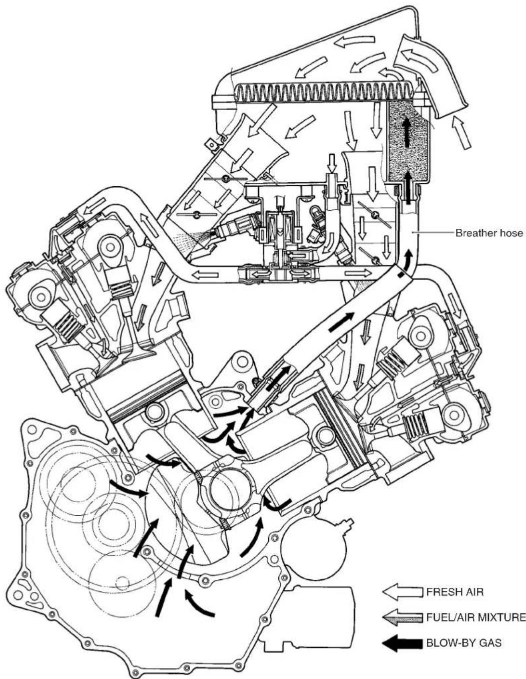
EXHAUST EMISSION CONTROL SYSTEM (PAIR SYSTEM)
The exhaust emission control system is composed of the PAIR system and THREE-WAY CATALYST system. The fresh air is drawn into the exhaust port with the PAIR solenoid valve and PAIR reed valve. The PAIR solenoid valve is operated by the ECM, and the fresh air flow is controlled according to the TPS, ECTS, IATS, IAPS and CKPS.

TAMPERING WITH THE NOISE CONTROL SYSTEM PROHIBITED: Local law prohibits the following acts or the causing thereof:
- The removal or rendering inoperative by any person, other than for purposes of maintenance, repair or replacement, of any device or element of design incorporated into any new vehicle for the purpose of noise control prior to its sale or delivery to the ultimate purchaser or while it is in use, or
- The use of the vehicle after such device or element of design has been removed or rendered inoperative by any person.
AMONG THOSE ACTS PRESUMED TO CONSTITUTE TAMPERING ARE THE ACTS LISTED BELOW:
- Removing or puncturing the muffler, baffles, header pipes, screen type spark arrester (if equipped) or any other component which conducts exhaust gases.
- Removing or puncturing the air cleaner case, air cleaner cover, baffles or any other component which conducts intake air.
- Replacing the exhaust system or muffler with a system or muffler not marked with the same model specific code as the code listed on the Motorcycle Noise Emission Control Information label.
EVAPORATIVE EMISSION CONTROL SYSTEM (Only for E-33)
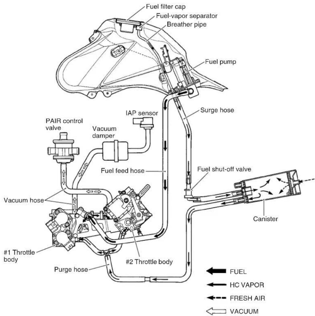
PAIR (AIR SUPPLY) SYSTEM INSPECTION HOSES
- Inspect the hoses for wear or damage.
- Inspect that the hoses are securely connected.
PAIR REED VALVE
- Remove the PAIR reed valve cover.
- Inspect the reed valve for the carbon deposit.
- If the carbon deposit is found in the reed valve, replace the PAIR reed valve with a new one

natural_image
Black rectangular electronic device with two terminals and a central display (no text or symbols visible)PAIR CONTROL VALVE (For E-03, 24, 28 and 33)
- Remove the air cleaner box and PAIR control valve.
- Check that air flows through the PAIR control valve air inlet port to the air outlet ports.
- If air does not flow out, replace the PAIR control valve with a new one.

- Connect the vacuum pump gauge to the vacuum port of the control valve as shown in the illustration.
- Apply negative pressure of the specification slowly to the control valve and inspect the air flow.
- If air does not flow to the pump, the control valve is in normal condition.
- If the control valve does not properly function within the specification, replace the control valve with a new one.

natural_image
Technical line drawing of a mechanical valve assembly with pressure gauge and actuator (no text or labels)
Negative pressure range: -53.3 kPa (-392 mmHg)

09917-47010: Vacuum pump gauge
CAUTION
Use a hand operated vacuum pump to prevent the control valve damage.
- Installation is in the reverse order of removal.
PAIR CONTROL SOLENOID VALVE (For E-02 and 19)
- Disconnect the PAIR control solenoid valve lead wire coupler.
- Remove the air cleaner box.
-
Remove the PAIR control solenoid valve.
-
Check that air flows through the air inlet port to the air outlet ports.
-
If air does not flow out, replace the PAIR control solenoid valve with a new one.
-
Connect the 12 V battery to the PAIR control solenoid valve terminals and check the air flow.
- If air does not flow out, the solenoid valve is in normal condition.
- Check the resistance between the terminals of the PAIR control solenoid valve.

Resistance: 20 - 24 Ω (at 20 °C/68 °F)

09900-25008: Multi circuit tester set

Tester knob indication: Resistance (Ω)

natural_image
Close-up of a metallic mechanical component with multiple ports and a handle, no visible text or symbols.

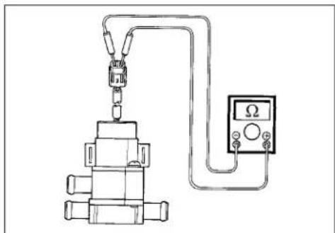
natural_image
Technical line drawing of a mechanical testing setup with a clamp, coil, and digital multimeter (no text or symbols)If the resistance is not within the standard range, replace the PAIR control solenoid valve with a new one.
- Connect the PAIR control solenoid valve lead wire coupler securely.
• Installation is in the reverse order of removal.
PAIR (AIR SUPPLY) SYSTEM HOSE ROUTING
For European markets
For USA/CANADA/AUSTRALIA


HEATED OXGEN SENSOR (HO₂S) INSPECTION
- Remove the engine under cover.
- Disconnect the HO2 sensor lead wire coupler.
- Remove the HO 2 sensor unit.
WARNING
Do not remove the HO2 sensor while it is hot.
CAUTION
Be careful not to expose it to excessive shock.
Do not use an impact wrench while removing or installing the HO 2 sensor unit.
Be careful not to twist or damage the sensor lead wire.
- Inspect the HO 2 sensor and its circuit referring to flow table of the malfunction code (C44).
- Disconnect the HO 2 sensor coupler.
- Check the resistance between the terminals of the HO 2 sensor.
DATA Resistance: 4 – 5 Ω (at 23 °C/73.4 °F)
09900-25008: Multi circuit tester set
Tester knob indication: Resistance (Ω)
If the resistance is not within the standard range, replace the HO2 sensor with new one.
NOTE:
* Temperature of the sensor affects resistance value largely.
* Make sure that the sensor heater is at correct temperature.
- Connect the HO 2 sensor coupler securely.
- Installation is in the reverse order of removal.
CAUTION
Do not apply oil or other materials to the sensor air hole.
- Tighten the sensor unit to the specified torque.
H∅SENSOR: 47.5 N·m (4.75 kgf-m, 34.3 lb-ft)
- Route the HO 2 sensor lead wire into the frame.
- Connect the HO 2 sensor coupler.
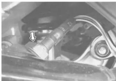
natural_image
Close-up of a mechanical component with a white arrow pointing to a component (no visible text or symbols)

natural_image
Technical line drawing of a mechanical assembly with a tool inserted, no visible text or symbolsHEATED OXGEN SENSOR WIRE ROUTING

EVAPORATIVE EMISSION CONTROL SYSTEM INSPECTION (Only for E-33)
- Remove the seat and frame cover.
- Remove the fuel tank. (4-56)
HOSES
Inspect the hoses for wear or damage.
Make sure that the hoses are securely connected.
CANISTER
Inspect the canister for damage to the body.
CANISTER HOSE ROUTING (Only for E-33)


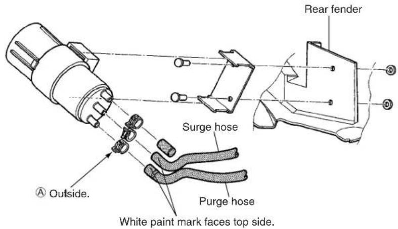
Ⓐ Clamp ends should face......
This chapter describes service specifications, service data and servicing procedures which differ from those of the DL1000K2 ('02-MODEL).
NOTE:
* Any differences between the DL1000K2 ('02-model) and DL1000K3 ('03-model) in specifications and service data are indicated with an asterisk mark (*).
* Please refer to the chapters 1 through 9 for details which are not given in this chapter.
CONTENTS
SPECIFICATIONS 10-2
SERVICE DATA 10-4
FRONT FORK 10-14
REGULATOR/RECTIFIER INSPECTION 10-15
SPECIFICATIONS
DIMENSIONS AND DRY MASS
Overall length.... 2 295 mm (90.4 in)
Overall width 865 mm (34.1 in)
Overall height.... 1 335 mm (52.6 in)
Wheelbase 1 535 mm (60.4 in)
Ground clearance 165 mm (6.5 in)
Seat height.... 840 mm (33.1 in)
Dry mass.... 207 kg (456 lbs)
209 kg (461 lbs) .....E-33
ENGINE
Type Four-stroke, Liquid-cooled, DOHC, 90-degree V-twin
Number of cylinders 2
Bore 98.0 mm (3.858 in)
Stroke.... 66.0 mm (2.598 in)
Piston displacement.... 996 cm 3 (60.8 cu. in)
Compression ratio.... 11.3 : 1
Fuel system.... Fuel injection system
Air cleaner.... Non-woven fabric element
Starter system..... Electric starter
Lubrication system ...... Wet sump
DRIVE TRAIN
Clutch.... Wet multi-plate type
Transmission.... 6-speed constant mesh
Gearshift pattern 1-down, 5-up
Primary reduction ratio.... 1.838 (57/31)
Final reduction ratio 2.411 (41/17)
Gear ratios, Low 3.000 (36/12)
2nd....1.933 (29/15)
3rd 1.500 (27/18)
4th....1.227 (27/22)
5th.... 1.086 (25/23)
Top 0.913 (21/23)
Drive chain RK525 SMOZ7, 112 links
CHASSIS
Front suspension...... Inverted telescopic, coil spring, oil damped
Rear suspension .... Link type, coil spring, oil damped
Steering angle 40° (right & left)
Caster.... 26° 30'
Trail 111 mm (4.3 in)
Turning radius 2.7 m (8.86 ft)
Front brake.... Disc brake, twin
Rear brake .... Disc brake
Front tire size 110/80 R19M/C 59H, tubeless
Rear tire size 150/70 R17M/C 69H, tubeless
Front fork stroke 160 mm (6.3 in)
Rear wheel travel 159 mm (6.2 in)
ELECTRICAL
Ignition type ...... Electronic ignition (ECM, Transistorized)
Ignition timing 4° B.T.D.C at 1 200 r/min
Spark plug ...... NGK: CR8EK or DENSO: U24ETR
Battery 12 V 43.2 kC (12 Ah)/10 HR
Generator .... Three-phase A.C. Generator
Fuse 30/15/15/15/15/15/10 A
Headlight 12 V 60/55 W H4
Position light.... 12 V 5 W × 2.....Except for E-03, 24, 28, 33
Turn signal/Hazard light 12 V 10 W
License light 12 V 5 W
Brake light/Taillight 12 V 21/5 W × 2
Speedometer/Tachometer light...... LED
Neutral indicator light ...... LED
High beam indicator light...... LED
Turn signal indicator light ...... LED
Over drive indicator light ...... LED
Fuel injector warning light ...... LED
Engine coolant temperature warning light...... LED
Oil pressure warning light...... LED
CAPACITIES
Fuel tank 22 L (5.8/4.8 US/Imp gal)
Engine oil, oil change 2700 ml (2.9/2.4 US/lmp qt)
with filter change.... 2 900 ml (3.1/2.6 US/Imp qt)
overhaul 3 300 ml (3.5/2.9 US/Imp qt)
Engine coolant, including reserve 2 200 ml (2.3/1.9 US/lmp oz)
Front fork oil (each leg) 505 ml (17.1/17.8 US/Imp oz)
SERVICE DATA
VALVE + GUIDE Unit: mm (in)
| ITEM STANDARD | LIMIT | ||
| Valve diam. | IN. | 36(1.42) | — |
| EX. | 33(1.30) | — | |
| Tappet clearance (when cold) | IN. | 0.10 – 0.20(0.004 – 0.008) | — |
| EX. | 0.20 – 0.30(0.008 – 0.012) | — | |
| Valve guide to valve stem clearance | IN. | 0.010 – 0.037(0.0004 – 0.0015) | — |
| EX. | 0.030 – 0.057(0.0012 – 0.0022) | — | |
| Valve guide I.D. | IN. & EX. | 5.500 – 5.512(0.2165 – 0.2170) | — |
| Valve stem O.D. | IN. | 5.475 – 5.490(0.2156 – 0.2161) | — |
| EX. | 5.455 – 5.470(0.2148 – 0.2154) | — | |
| Valve stem deflection | IN. & EX. — | 0.35(0.014) | |
| Valve stem runout | IN. & EX. — | 0.05(0.002) | |
| Valve head thickness | IN. & EX. — | 0.5(0.02) | |
| Valve seat width | IN. & EX. | 0.9 – 1.1(0.035 – 0.043) | — |
| Valve head radial runout | IN. & EX. — | 0.03(0.001) | |
| Valve spring free length | IN. & EX. — | 39.6(1.56) | |
| Valve spring tension | IN. & EX. | 197 – 227 N(20.1 – 23.1 kgf, 44.3 – 51.0 lbs)at length 35.6 mm (1.40 in) | — |
CAMSHAFT + CYLINDER HEAD Unit: mm (in)
| ITEM STANDARD | LIMIT | ||
| Cam height | IN. | 36.28 – 36.32(1.428 – 1.430) | 35.98(1.417) |
| EX. | 35.68 – 35.72(1.405 – 1.406) | 35.38(1.393) | |
| Camshaft journal oil clearance | IN. & EX. | 0.019 – 0.053(0.0007 – 0.0021) | 0.150(0.0059) |
| Camshaft journal holder I.D. | IN. & EX. | 22.012 – 22.025(0.8666 – 0.8671) | — |
| Camshaft journal O.D. | IN. & EX. | 21.972 – 21.993(0.8650 – 0.8659) | — |
| Camshaft runout | IN. & EX. — | 0.10(0.004) | |
| Cam drive idle gear/sprocket thrust clearance | 0.15 – 0.29(0.006 – 0.011) | — | |
| Cylinder head distortion | — | 0.05(0.002) | |
CYLINDER + PISTON + PISTON RING Unit: mm (in)
| ITEM STANDARD LIMIT | |||
| Compression pressure(Automatic de-comp. actuated) | 1 000 – 1 400 kPa(10 – 14 kgf/cm2, 142 – 199 psi) | 800 kPa(8 kgf/cm2, 114 psi) | |
| Compression pressure difference | — | 200 kPa(2 kgf/cm2, 28 psi) | |
| Piston to cylinder clearance 0.015 – 0.025(0.0006 – 0.0010) | 0.12(0.0047) | ||
| Cylinder bore 98.000 – 98.015 | (3.8583 – 3.8589) | Nicks orScratches | |
| Piston diam. 97.980 – 97.995 | (3.8575 – 3.8581)Measure at 10 mm (0.4 in) from the skirt end. | 97.880(3.8535) | |
| Cylinder distortion | — | 0.05(0.002) | |
| Piston ring free end gap | 1st Approx. 8.8 (0.35) | 7.0(0.28) | |
| 2nd Approx. 10.1 (0.40) | 8.1(0.32) | ||
| Piston ring end gap | 1st | 0.15 – 0.35(0.006 – 0.014) | 0.5(0.02) |
| 2nd RN | 0.30 – 0.45(0.012 – 0.018) | 0.7(0.03) | |
| Piston ring to groove clearance | 1st | — | 0.18(0.0071) |
| 2nd | — | 0.15(0.0059) | |
| ITEM STANDARD | LIMIT | ||
| Piston ring groove width | 1st | 0.93 – 0.95(0.0366 – 0.0374) | — |
| 1.55 – 1.57(0.0610 – 0.0618) | — | ||
| 2nd | 1.01 – 1.03(0.0398 – 0.0406) | — | |
| Oil | 2.51 – 2.53(0.0988 – 0.0996) | — | |
| Piston ring thickness | 1st | 0.86 – 0.91(0.034 – 0.036) | — |
| 1.38 – 1.40(0.054 – 0.055) | — | ||
| 2nd | 0.97 – 0.99(0.038 – 0.039) | — | |
| Piston pin bore I.D. 22.002 – 22.008 | 22.030(0.8673) | ||
| Piston pin O.D. 21.992 – 22.000 | (0.8662 – 0.8665) | 21.980(0.8654) | |
CONROD + CRANKSHAFT Unit: mm (in)
| ITEM STANDARD | LIMIT | |
| Conrod small end I.D. 22.010 – | 22.018(0.8665 – 0.8668) | 22.040(0.8677) |
| Conrod big end side clearance 0. | 17 – 0.32(0.007 – 0.013) | 0.50(0.020) |
| Conrod big end width 21.95 – 22.00 | — | |
| Crank pin width 44.17 – 44.22 | (1.739 – 1.741) | — |
| Conrod big end oil clearance | 0.040 – 0.064(0.0016 – 0.0025) | 0.080(0.0031) |
| Crank pin O.D. | 44.976 – 45.000(1.7707 – 1.7717) | — |
| Crankshaft journal oil clearance | 0.002 – 0.029(0.0008 – 0.0011) | 0.080(0.0031) |
| Crankshaft journal O.D. | 47.985 – 48.000(1.8892 – 1.8898) | — |
| Crankshaft journal holder width | 25.2 – 25.4(0.99 – 1.00) | — |
| Crankshaft journal width | 25.50 – 25.55(1.004 – 1.006) | — |
| Crankshaft runout | — | 0.05(0.004) |
OIL PUMP
| ITEM STANDARD LIMIT | ||
| Oil pressure (at 60°C, 140°F) Above 400 kPa (4.0 kgf/cm2, 57 psi) Below 700 kPa (7.0 kgf/cm2, 100 psi) at 3 000 r/min | — | |
CLUTCH
Unit: mm (in)
| ITEM STANDARD LIMIT | |||
| Drive plate thickness | No.1 | 2.92 – 3.08(0.115 – 0.121) | 2.62(0.103) |
| No. 2 and 3 | 3.72 – 3.88(0.146 – 0.153) | 3.42(0.135) | |
| Drive plate claw width | No.1 | 13.85 – 13.96(0.545 – 0.550) | 13.05(0.514) |
| No. 2 and 3 | 13.90 – 14.00(0.547 – 0.551) | 13.10(0.516) | |
| Driven plate distortion | — | 0.10(0.004) | |
| Clutch spring free length 61.5 – 62.5 | 59.4(2.34) | ||
| Clutch master cylinder bore 14.000 – 14.043 | — | ||
| Clutch master cylinder piston diam. | 13.957 – 13.984(0.5495 – 0.5505) | — | |
| Clutch release cylinder bore 35.700 – 35.762 | (1.4055 – 1.4079) | — | |
| Clutch release cylinder piston diam. | 35.650 – 35.675(1.4035 – 1.4045) | — | |
THERMOSTAT + RADIATOR + FAN
| ITEM STANDARD LIMIT | |||
| Thermostat valve opening temperature | 86.5 – 89.5 °C(188 – 193 °F) | — | |
| Thermostat valve lift Over 8 mm (0.31 in) at 100 °C (212 °F) — | |||
| Radiator cap valve opening pressure | 110 kPa (1.1 kgf/cm2, 15.6 psi) — | ||
| Cooling fan thermoswitch operating temperature | ON→OFF | Approx. 105 °C (221°F) — | |
| ON→OFF | Approx. 100 °C (212°F) — | ||
| Engine coolant temperature sensor resistance | 20 °C(68 °F) | Approx. 2.45 kΩ — | |
| 40 °C(104 °F) | Approx. 1.148 kΩ — | ||
| 60 °C(140 °F) | Approx. 0.587 kΩ — | ||
| 80 °C(176 °F) | Approx. 0.322 kΩ — | ||
DRIVE TRAIN Unit: mm (in) Expect ratio
| ITEM STANDARD | LIMIT | |||
| Primary reduction ratio 1.838 (57/31) — | ||||
| Final reduction ratio 2.411 (41/17) — | ||||
| Gear ratio Low 3.000 | (36/12) — | |||
| 2nd 1.933 (29/15) — | ||||
| 3rd 1.500 (27/18) — | ||||
| 4th 1.227 (27/22) — | ||||
| 5th 1.086 (25/23) — | ||||
| Top 0.913 (21/23) — | ||||
| Shift fork to groove clearance 0.1 | -0.3(0.004 – 0.012) | 0.50(0.020) | ||
| Shift fork groove width 5.0 – 5.1 | (0.197 – 0.201) | — | ||
| Shift fork thickness | 4.8 – 4.9(0.189 – 0.193) | — | ||
| Drive chain | Type | RK525SMOZ7 | — | |
| Links | 112 links, ENDLESS | — | ||
| 20-pitch length | — | 319.4(12.6) | ||
| Drive chain slack | 20 – 30(0.8 – 1.2) | — | ||
| Gearshift lever height | 25(1.0) | — | ||
INJECTOR + FUEL PUMP + FUEL PRESSURE REGURATOR
| ITEM | SPECIFICATION NOTE | |
| Injector resistance | 12 – 18 Ω at 20 °C (68°F) | |
| Fuel pump discharge amount | Approx. 1.2 L (1.3/1.1 US/lmp qt)for 1 minute at 300 kPa (3.0 kgf/cm2, 43 psi) | |
| Fuel pressure regulator operating set pressure | Approx. 300 kPa (3.0 kgf/cm2, 43 psi) |
FI-SENSORS
| ITEM SPECIFICATION NOTE | |||
| CMP sensor output voltage More | than 3.7 V | ||
| CKP sensor resistance 130 – 240 Ω | |||
| CKP sensor peak voltage More than 3.7 V (When cranking) | |||
| IAP sensor input voltage 4.5 – 5.5 V | |||
| IAP sensor output voltage Approx. 2.5 V at idle speed | |||
| TP sensor input voltage 4.5 – 5.5 V | |||
| TP sensor resistance | Closed | Approx. 1.1 kΩ | |
| Opened | Approx. 4.3 kΩ | ||
| TP sensor output voltage | Closed | Approx. 1.1 V | |
| Opened | Approx. 4.3 V | ||
| ECT sensor input voltage 4.5 – 5.5 V | |||
| ECT sensor resistance Approx. 2.45 kΩ at 20 °C (68°F) | |||
| IAT sensor input volatage 4.5 – 5.5 V | |||
| IAT sensor resistance Approx 2.45 kΩ at 20 °C (68°F) | |||
| AP sensor input voltage 4.5 – 5.5 V | |||
| AP sensor output voltage Approx. 4.0 V at 760 mmHg (100 kPa) | |||
| TO sensor resistance | 19.1 – 19.7 kΩ | ||
| TO sensor voltage | Approx. 0.4 – 1.4 V | ||
| GP switch voltage | More than 1.0 V (From 1st to top) | ||
| Injector voltage | Battery voltage | ||
| Ignition coil primary peak voltage | More than 150 V (When cranking) | ||
| STP sensor input voltage 4.5 – 5.5 V | |||
| STP sensor resistance | Closed | Approx. 1.1 kΩ | |
| Opened | Approx. 4.3 kΩ | ||
| STP sensor output voltage | Closed | Approx. 1.1 V | |
| Opened | Approx. 4.3 V | ||
| STV actuator resistance | 4.8 – 7.2 Ω | ||
| Heated oxygen sensor output voltage | less than 0.4 V at idle speed(After warming up) | European markets | |
| Heated oxygen sensor resistance | 4 – 5 Ω at 23 °C (73.4 °F) | ||
| PAIR solenoid valve resistance | 20 – 24 Ω at 20 °C (68 °F) | ||
THROTTLE BODY
| ITEM | SPECIFICATION |
| ID No. | 06G0 (For E-02, 19), 06G1 (For E-33), 06G2 (For E-03, 24, 28) |
| Bore size | 45 mm |
| Fast idle r/min | 1 500 – 2 100 r/min at 25 °C (77 °F) |
| Idle r/min | 1 200 ± 100 r/min/Warmed engine |
| Throttle cable play | 2.0 – 4.0 r/min(0.08 – 0.16 in) |
ELECTRICAL Unit: mm (in)
| ITEM SPECIFICATION NOTE | ||||
| Ignition timing 4° B.T.D.C. at 1 200 r/min | ||||
| Firing order 1·2 | ||||
| Spark plug | Type | NGK: CR8EKDenso: U24ETR | ||
| Gap | 0.6 - 0.7(0.024 - 0.028) | |||
| Spark performance Over 8 (0.3) at 1 atm. | ||||
| Crankshaft position sensor resistance | 130 - 240 Ω BI - G | |||
| Ignition coil resistance Primary 2 | -5 Ω | |||
| Secondary 24 | -37 kΩ | |||
| Crankshaft position sensor peak voltage | More than 3.7 V When cranking | |||
| Ignition coil primary peak voltage | More than 150 V When cranking | |||
| Generator coil resistance 0.2 - 0.5 Ω Y - Y | ||||
| Generator Max. output | Approx. 400 W at 5 000 r/min | |||
| Generator no-load voltage(When engine is cold) | More than 75 V (AC) at 5 000 r/min | |||
| Regulated voltage | 14.0 - 15.5 V at 5 000 r/min | |||
| Starter relay resistance 3 - 6 Ω | ||||
| Battery | Type designation | FTX14-BS | ||
| Capacity | 12 V 43.2 kC (12 Ah)/10 HR | |||
| Fuse size | Headlight | HI | 15 A | |
| LO | 15 A | |||
| Turn signal | 15 A | |||
| Ignition | 15 A | |||
| Fan motor | 15 A | |||
| Meter | 10 A | |||
| Main | 30 A | |||
WATTAGE Unit: W
| ITEM | SPECIFICATION | ||
| E-03, 24, 28, 33 The others | |||
| Headlight | HI 60 × 2 ← | ||
| LO 55 × 2 ← | |||
| Position light 5 × 2 | |||
| Brake light/Taillight 21/5 × 2 ← | |||
| Turn signal light 10 × 4 ← | |||
| Speedometer/Tachometer light LED | ← | ||
| Turn signal indicator light | LED | ← | |
| High beam indicator light | LED | ← | |
| Neutral indicator light | LED | ← | |
| Over drive indicator light | LED | ← | |
| Coolant temperature warning light | LED | ← | |
| Oil pressure warning light | LED | ← | |
| Fuel injection warning light | LED | ← | |
| License light | 5 | ← | |
BRAKE + WHEEL Unit: mm (in)
| ITEM | STANDARD | LIMIT | |
| Rear brake pedal height | 20 – 30(0.8 – 1.2) | — | |
| Brake disc thickness | Front | 5.0 ± 0.2(0.197 ± 0.008) | 4.5(0.18) |
| Rear | 5.0 ± 0.2(0.197 ± 0.008) | 4.5(0.18) | |
| Brake disc runout(Front & Rear) | — | 0.30(0.012) | |
| Master cylinder bore | Front | 15.870 – 15.913(0.6248 – 0.6265) | — |
| Rear | 14.000 – 14.043(0.5512 – 0.5529) | — | |
| Master cylinder piston diam. | Front | 15.827 – 15.854(0.6231 – 0.6242) | — |
| Rear | 13.957 – 13.984(0.5495 – 0.5506) | — | |
| Brake caliper cylinder bore | Front | 30.230 – 30.306(1.1902 – 1.1931) | — |
| Rear | 38.180 – 38.230(1.5031 – 1.5051) | — | |
| Brake caliper piston diam. | Front | 30.150 – 30.200(1.1870 – 1.1890) | — |
| Rear | 38.098 – 38.148(1.4999 – 1.5019) | — | |
| Wheel rim runout(Front & Rear) | Axial | — | 2.0(0.08) |
| Radial | — | 2.0(0.08) | |
| ITEM STANDARD | LIMIT | ||
| Wheel axle runout | Front — | 0.25(0.010) | |
| Rear — | 0.25(0.010) | ||
| Wheel rim size Front 19M/C × MT | 2.50 — | ||
| Rear 17M/C × MT 4.00 — | |||
| Tire size Front 110/80R19M/C 5 | 9H — | ||
| Rear 150/70R17M/C 69H — | |||
| Tire type Front BRIDGESTONE: TW101 F — | |||
| Tire tread depth | Front — | 1.6(0.06) | |
| Rear — | 2.0(0.08) | ||
SUSPENSION Unit: mm (in)
| ITEM | STANDARD LIMIT | ||
| Front fork stroke | 160(6.3) | — | |
| Front fork spring free length | * 433.6(17.07) | * 424(16.7) | |
| Front fork oil level(without spring, inner tube fully compressed) | * 140.0(5.51) | — | |
| Front fork oil type | SUZUKI FORK OIL SS-08 or an equivalent fork oil | ||
| Front fork oil capacity (each leg) | * 496.0 ml(16.76/17.46 US/lmp oz) | ||
| Front fork spring adjuster | * 3rd groove from top | — | |
| Rear shock absorber spring adjuster | 2nd groove from bottom | — | |
| Rear shock absorber damping force adjuster | Rebound | 7/8 turn out from stiffest position | — |
| Rear wheel travel | 159(6.3) | — | |
| Swingarm pivot shaft runput | — | 0.3(0.01) | |
TIRE PRESSURE
| COLD INFLATIONTIRE PRESSURE | SOLO RIDING | DUAL RIDING | ||||
| kPa | kgf/cm2 | psi | kPa | kgf/cm2 | psi | |
| FRONT | 250 | 2.50 | 36 | 250 | 2.50 | 36 |
| REAR | 250 | 2.50 | 36 | 280 | 2.80 | 41 |
FUEL + OIL + ENGINE COOLANT
| ITEM SPECIFICATION NOTE | |||
| Fuel type Use only unleaded | gasoline of at least 87 pump octane (R/2 + M/2) or 91 octane or higher rated by the research method. Gasoline containing MTBE (Methyl Tertiary Butyl Ether), less than 10% ethanol, or less than 5% methanol with appropriate cosolvents and corrosion inhibitor is permissible. | E-03, 28, 33 | |
| Gasoline used should be graded 91 octane or higher. An unleaded gasoline is recommended. | The others | ||
| Fuel tank 17L | (4.5/3.7 US/lmp gal) | ||
| Engine oil type SAE 10W-40, API | SF or SG | ||
| Engine oil capacity | Change | 2 700 ml(2.9/2.4 US/lmp qt) | |
| Filter change | 2 900 ml(3.1/2.6 US/lmp qt) | ||
| Overhaul | 3 300 ml(3.5/2.9 US/lmp qt) | ||
| Brake fluid type DOT 4 | |||
| Engine coolant type Use an anti-freeze/coolant compatible with aluminum radiator, mixed with distilled water only, at the ratio of 50:50. | |||
| Engien coolant Reserve tank | side | Approx. 250 ml(0.3/0.2 US/lmp qt) | |
| Engine side | Approx. 1 950 ml(2.1/1.7 US/lmp qt) | ||
FRONT FORK
CONSTRUCTION
① Spring adjuster
② O-ring
③ O-ring
④ Spring seat
⑤ Spacer
⑥ Washer
⑦ Spring
⑧ Inner rod/damper rod (cartridge)
⑨ Inner tube
⑩ Dust seal
⑪ Oil seal stopper ring
⑫ Oil seal
⑬ Oil seal retainer
⑭ Guide metal
⑮ Slide metal
⑯ Oil lock piece
⑰ Outer tube
Ⓐ Front fork cap bolt
⑧ Inner rod lock nut
© Front axle pinch bolt
(D) Damper rod bolt

U
| ITEM | N·m kgf·m | lb·ft | |
| A | 23 2.3 | 16.5 | |
| B | 20 2.0 | 14.5 | |
| C | 23 2.3 | 16.5 | |
| D | 20 2.0 | 14.5 |
SUSPENSION SETTING
After installing the front fork, adjust the spring pre-load as follows.
SPRING PRE-LOAD ADJUSTMENT
There are five grooved lines on the side of the spring adjuster. Position 0 provides the maximum spring pre-load and position 5 provides the minimum spring pre-load.
(STD position: "3")

WARNING
Be sure to adjust the spring pre-load on both front fork legs equally.

REGULATOR/RECTIFIER INSPECTION
Using the multi circuit tester, measure the voltage between the lead wires in the following table.
If voltage is incorrect, replace the regulator/rectifier.

09900-25008: Multi circuit tester set

Tester knob indication: Diode test ( → )
Unit: V
| ⊕ Probe of tester to: | ||||||
| Probe of tester to: | R | B1 | B2 | B3 | B/W | |
| R | 0 - 0.7 | 0.4 - 0.7 | 0.4 - 0.7 | 0.5 4 0.8 | ||
| B1 1.4 | -1.5 | 1.4 | -1.5 | 1.4 - 1.5 | 0.4 - 0.7 | |
| B2 1.4 | -1.5 | 1.4 - 1.5 | 1.4 | -1.5 | 0.4 - 0.7 | |
| B3 1.4 | -1.5 | 1.4 - 1.5 | 1.4 - 1.5 | 0.4 | -0.7 | |
| B/W 1.4 | -1.5 | 1.4 - 1.5 | 1.4 - 1.5 | 1.4 - 1.5 | ||

G: Gray, R: Red, B/W: Black with White tracer
NOTE:
If the tester reads under 1.4 V when the tester probes are not connected, replace the battery of multi circuit tester.
DL1000K4 ('04-MODEL)
This chapter describes service specifications, service data and servicing procedures which differ from those of the DL1000K3 ('03-MODEL).
NOTE:
* Any differences between the DL1000K3 ('03-model) and DL1000K4 ('04-model) in specifications and service data are indicated with an asterisk mark (*).
* Please refer to the chapters 1 through 10 for details which are not given in this chapter.
CONTENTS
SPECIFICATIONS 11-2
SERVICE DATA 11-3
SPECIAL TOOL 11-12
FI SYSTEM 11-15
COMBINATION METER 11-16
WIRE HARNESS ROUTING 11-22
COWLING SETUP 11-24
SPECIFICATIONS
DIMENSIONS AND DRY MASS
Overall length 2 295 mm (90.4 in)
Overall width 910 mm (35.8 in)
Overall height....* 1 395 mm (54.9 in)
Wheelbase 1 535 mm (60.4 in)
Ground clearance.... 165 mm (6.5 in)
Seat height 840 mm (33.1 in)
Dry mass....* 208 kg (458 lbs)
* 210 kg (462 lbs)...... E-33
ENGINE
Type.... 4-stroke, Liquid-cooled, DOHC, 90° degree V-twin
Number of cylinders 2
Bore 98.0 mm (3.858 in)
Stroke 66.0 mm (2.598 in)
Displacement 996 cm 3 (60.8 cu. in)
Compression ratio.... 11.3 : 1
Fuel system.... Fuel injection system
Air cleaner...... Non-woven fabric element
Starter system..... Electric
Lubrication system Wet sump
Idle speed 1 200 ± 100 r/min
DRIVE TRAIN
Clutch Wet multi-plate type
Transmission 6-speed constant mesh
Gearshift pattern 1-down, 5-up
Primary reduction ratio.... 1.838 (57/31)
Gear ratios, Low.... 3.000 (36/12)
2nd 1.933 (29/15)
3rd 1.500 (27/18)
4th 1.227 (27/22)
5th 1.086 (25/23)
Top....0.913 (21/23)
Final reduction ratio....2.411 (41/17)
Drive chain RK525 SMOZ7, 112 links
CHASSIS
Front suspension...... Telescopic, coil spring, oil damped
Rear suspension.... Link type, coil spring, oil damped
Front suspension stroke 160 mm (6.3 in)
Rear wheel travel 159 mm (6.3 in)
Caster 26° 30'
Trail.... 111 mm (4.4 in)
Steering angle 40° (right & left)
Turning radius 2.7 m (8.86 ft)
Front brake.... Disk brake, twin
Rear brake .... Disk brake
Front tire size 110/80 R19M/C 59H, tubeless
Rear tire size 150/70 R17M/C 69H, tubeless
ELECTRICAL
Ignition type...... Electronic ignition (Transistorized)
Ignition timing 4° B.T.D.C. at 1 200 r/min
Spark plug.... NGK CR8EK or DENSO U24ETR
Battery.... 12V 43.2 kC (12Ah)/10 HR
Generator.... Three-phase A.C. generator
Main fuse 30 A
Fuse 10/10/15/15/15/15 A
Headlight 12 V 60/55 W × 2 (H4 × 2)
Position/Parking light.... 12 V 5 W × 2.... Except E-03, 24, 28, 33
Brake light/Taillight 12 V 21/5 W × 2
License plate light 12 V 5 W
Turn signal /Hazard light ....* 12 V 21 W
Speedometer light...... LED
Tachometer light...... LED
Turn signal indicator light LED
Neutral indicator light LED
High beam indicator light LED
Fuel injection warning light...... LED
(Coolant temperature, Oil pressure)
CAPACITIES
Fuel tank 22 L (5.81/4.84 US/Imp gal)
Engine oil, oil change.... 2 700 ml (2.9/2.4 US/lmp qt)
with filter change.... 2 900 ml (3.1/2.6 US/lmp qt)
overhaul 3 300 ml (3.5/2.9 US/Imp qt
Coolant.... 2.2 L (2.3/1.9 US/Imp qt)
SERVICE DATA
VALVE + GUIDE Unit: mm (in)
| ITEM STANDARD | LIMIT | ||
| Valve diam. | IN. | 36(1.42) | — |
| EX. | 33(1.30) | — | |
| Tappet clearance (when cold) | IN. | 0.10 – 0.20(0.004 – 0.008) | — |
| EX. | 0.20 – 0.30(0.008 – 0.012) | — | |
| Valve guide to valve stem clearance | IN. | 0.010 – 0.037(0.0004 – 0.0015) | — |
| EX. | 0.030 – 0.057(0.0012 – 0.0022) | — | |
| Valve guide I.D. | IN. & EX. | 5.500 – 5.512(0.2165 – 0.2170) | — |
| Valve stem O.D. | IN. | 5.475 – 5.490(0.2156 – 0.2161) | — |
| EX. | 5.455 – 5.470(0.2148 – 0.2154) | — | |
| Valve stem deflection | IN. & EX. — | 0.35(0.014) | |
| Valve stem runout | IN. & EX. — | 0.05(0.002) | |
| Valve head thickness | IN. & EX. — | 0.5(0.02) | |
| Valve seat width | IN. & EX. | 0.9 – 1.1(0.035 – 0.043) | — |
| Valve head radial runout | IN. & EX. — | 0.03(0.001) | |
| Valve spring free length | IN. & EX. — | 39.6(1.56) | |
| Valve spring tension | IN. & EX. | 197 – 227 N(20.1 – 23.1 kgf, 44.3 – 51.0 lbs)at length 35.6 mm (1.40 in) | — |
CAMSHAFT + CYLINDER HEAD Unit: mm (in)
| ITEM STANDARD | LIMIT | ||
| Cam height | IN. | 36.28 – 36.32(1.428 – 1.430) | 35.98(1.417) |
| EX. | 35.68 – 35.72(1.405 – 1.406) | 35.38(1.393) | |
| Camshaft journal oil clearance | IN. & EX. | 0.019 – 0.053(0.0007 – 0.0021) | 0.150(0.0059) |
| Camshaft journal holder I.D. | IN. & EX. | 22.012 – 22.025(0.8666 – 0.8671) | — |
| Camshaft journal O.D. | IN. & EX. | 21.972 – 21.993(0.8650 – 0.8659) | — |
| Camshaft runout | IN. & EX. | — | 0.10(0.004) |
| Cam drive idle gear/sprocket thrust clearance | 0.15 – 0.29(0.006 – 0.011) | — | |
| Cylinder head distortion | — | 0.05(0.002) | |
CYLINDER + PISTON + PISTON RING Unit: mm (in)
| ITEM STANDARD | LIMIT | |||
| Compression pressure (Automatic de-comp. actuated) | 1 000 – 1 400 kPa(10 – 14 kgf/cm2, 142 – 199 psi) | 800 kPa(8 kgf/cm2, 114 psi) | ||
| Compression pressure difference | — | 200 kPa(2 kgf/cm2, 28 psi) | ||
| Piston to cylinder clearance 0.015 – 0.025(0.0006 – 0.0010) | 0.12(0.0047) | |||
| Cylinder bore 98.000 – 98.015 | (3.8583 – 3.8589) | Nicks orScratches | ||
| Piston diam. 97.980 – 97.995 | (3.8575 – 3.8581)Measure at 10 mm (0.4 in) from the skirt end. | 97.880(3.8535) | ||
| Cylinder distortion | — | 0.05(0.002) | ||
| Piston ring free end gap | 1st Approx. 8.8 (0.35) | 7.0(0.28) | ||
| 2nd Approx. 10.1 (0.40) | 8.1(0.32) | |||
| Piston ring end gap | 1st | 0.15 – 0.35(0.006 – 0.014) | 0.5(0.02) | |
| 2nd RN | 0.30 – 0.45(0.012 – 0.018) | 0.7(0.03) | ||
| Piston ring to groove clearance | 1st | — | 0.18(0.0071) | |
| 2nd | — | 0.15(0.0059) | ||
| Piston ring groove width | 1st | 0.93 – 0.95(0.0366 – 0.0374) | — | |
| 1.55 – 1.57(0.0610 – 0.0618) | — | |||
| 2nd | 1.01 – 1.03(0.0398 – 0.0406) | — | ||
| Oil | 2.51 – 2.53(0.0988 – 0.0996) | — | ||
| Piston ring thickness | 1st | 0.86 – 0.91(0.034 – 0.036) | — | |
| 1.38 – 1.40(0.054 – 0.055) | — | |||
| 2nd | 0.97 – 0.99(0.038 – 0.039) | — | ||
| Piston pin bore I.D. 22.002 – 22.008 | 22.030(0.8673) | |||
| Piston pin O.D. 21.992 – 22.000 | (0.8658 – 0.8661) | 21.980(0.8654) | ||
CONROD + CRANKSHAFT Unit: mm (in)
| ITEM STANDARD LIMIT | ||
| Conrod small end I.D. 22.010 – 22.018 | (0.8665 – 0.8668) | 22.040(0.8677) |
| Conrod big end side clearance 0.17 – 0.32 | (0.007 – 0.013) | 0.50(0.020) |
| Conrod big end width 21.95 – 22.00 | (0.864 – 0.866) | — |
| Crank pin width 44.17 – 44.22 | (1.739 – 1.741) | — |
| Conrod big end oil clearance 0.040 – 0.064 | (0.0016 – 0.0025) | 0.080(0.0031) |
| Crank pin O.D. 44.976 – 45.000 | (1.7707 – 1.7717) | — |
| Crankshaft journal oil clearance 0.002 – 0.029 | (0.0008 – 0.0011) | 0.080(0.0031) |
| Crankshaft journal O.D. | 47.985 – 48.000(1.8892 – 1.8898) | — |
| Crankshaft journal holder width | 25.2 – 25.4(0.99 – 1.00) | — |
| Crankshaft journal width | 25.50 – 25.55(1.004 – 1.006) | — |
| Crankshaft runout | — | 0.05(0.004) |
OIL PUMP
| ITEM STANDARD | LIMIT | |
| Oil pressure (at 60°C, 140°F) Above 400 kPa (4.0 kgf/cm2, 57 psi)Below 700 kPa (7.0 kgf/cm2, 100 psi) at 3 000 r/min | — |
CLUTCH
Unit: mm (in)
| ITEM STANDARD | LIMIT | ||
| Drive plate thickness | No.1 | 2.92 – 3.08(0.115 – 0.121) | 2.62(0.103) |
| No. 2 and 3 | 3.72 – 3.88(0.146 – 0.153) | 3.42(0.135) | |
| Drive plate claw width | No.1 | 13.85 – 13.96(0.545 – 0.550) | 13.05(0.514) |
| No. 2 and 3 | 13.90 – 14.00(0.547 – 0.551) | 13.10(0.516) | |
| Driven plate distortion | — | 0.10(0.004) | |
| Clutch spring free length 61.5 – 62.5 | 59.4(2.34) | ||
| Clutch master cylinder bore 14.000 – 14.043 | — | ||
| Clutch master cylinder piston diam. | 13.957 – 13.984(0.5495 – 0.5505) | — | |
| Clutch release cylinder bore 35.700 – 35.762 | — | ||
| Clutch release cylinder piston diam. | 35.650 – 35.675(1.4035 – 1.4045) | — | |
THERMOSTAT + RADIATOR + FAN
| ITEM STANDARD | LIMIT | ||
| Thermostat valve opening temperature | 86.5 – 89.5 °C(188 – 193 °F) | — | |
| Thermostat valve lift Over 8 mm (0.31 in) at 100 °C (212 °F) — | |||
| Radiator cap valve opening pressure | 110 kPa (1.1 kgf/cm2, 15.6 psi) — | ||
| Cooling fan thermoswitch operating temperature | ON→OFF | Approx. 105 °C (221 °F) — | |
| ON→OFF | Approx. 100 °C (212 °F) — | ||
| Engine coolant temperature sensor resistance | 20 °C(68 °F) | Approx. 2.45 kΩ — | |
| 40 °C(104 °F) | Approx. 1.148 kΩ | — | |
| 60 °C(140 °F) | Approx. 0.587 kΩ | — | |
| 80 °C(176 °F) | Approx. 0.322 kΩ | — | |
DRIVE TRAIN Unit: mm (in) Expect ratio
| ITEM STANDARD LIMIT | |||
| Primary reduction ratio 1.838 (57/31) — | |||
| Final reduction ratio 2.411 (41/17) — | |||
| Gear ratio Low 3.000 (36/12) — | |||
| 2nd 1.933 (29/15) — | |||
| 3rd 1.500 (27/18) — | |||
| 4th 1.227 (27/22) — | |||
| 5th 1.086 (25/23) — | |||
| Top 0.913 (21/23) — | |||
| Shift fork to groove clearance 0.1 | -0.3(0.004 - 0.012) | 0.50(0.020) | |
| Shift fork groove width 5.0 - 5.1 | (0.197 - 0.201) | — | |
| Shift fork thickness | 4.8 - 4.9(0.189 - 0.193) | — | |
| Drive chain | Type | RK525SMOZ7 | |
| Links | 112 links, ENDLESS | ||
| 20-pitch length | — | ||
| Drive chain slack | 20 - 30(0.8 - 1.2) | — | |
| Gearshift lever height | 25(1.0) | — | |
INJECTOR + FUEL PUMP + FUEL PRESSURE REGURATOR
| ITEM | SPECIFICATION | NOTE |
| Injector resistance | 12 – 18 Ω at 20 °C (68 °F) | |
| Fuel pump discharge amount | Approx. 1.2 L (1.3/1.1 US/lmp qt)for 1 minute at 300 kPa (3.0 kgf/cm2, 43 psi) | |
| Fuel pressure regulator operating set pressure | Approx. 300 kPa (3.0 kgf/cm2, 43 psi) |
FI-SENSORS
| ITEM SPECIFICATION NOTE | |||
| CMP sensor output voltage More | than 3.7 V | ||
| CKP sensor resistance 130 – 240 | Ω | ||
| CKP sensor peak voltage More than 3.7 V (When cranking) | |||
| IAP sensor input voltage 4.5 – 5.5 V | |||
| IAP sensor output voltage Approx. 2.5 V at idle speed | |||
| TP sensor input voltage 4.5 – 5.5 V | |||
| TP sensor resistance Closed Approx. 1.1 kΩ | |||
| Opened Approx. 4.3 kΩ | |||
| TP sensor output voltage Closed | Approx. 1.1 V | ||
| Opened Approx. 4.3 V | |||
| ECT sensor input voltage | 4.5 – 5.5 V | ||
| ECT sensor resistance | Approx. 2.45 kΩ at 20 °C (68 °F) | ||
| IAT sensor input volatage | 4.5 – 5.5 V | ||
| IAT sensor resistance | Approx 2.45 kΩ at 20 °C (68 °F) | ||
| AP sensor input voltage | 4.5 – 5.5 V | ||
| AP sensor output voltage | Approx. 4.0 V at 760 mmHg (100 kPa) | ||
| TO sensor resistance | 19.1 – 19.7 kΩ | ||
| TO sensor voltage | Approx. 0.4 – 1.4 V | ||
| GP switch voltage | More than 1.0 V (From 1st to top) | ||
| Injector voltage | Battery voltage | ||
| Ignition coil primary peak voltage | More than 150 V (When cranking) | ||
| STP sensor input voltage | 4.5 – 5.5 V | ||
| STP sensor resistance | Closed Approx. 1.1 kΩ | ||
| Opened Approx. 4.3 kΩ | |||
| STP sensor output voltage | Closed Approx. 1.1 V | ||
| Opened | Approx. 4.3 V | ||
| STV actuator resistance | 4.8 – 7.2 Ω | ||
| Heated oxygen sensor output voltage | Less than 0.4 V at idle speed (After warming up) | European markets | |
| Heated oxygen sensor resistance | 4 – 5 Ω at 23 °C (73.4 °F) | ||
| PAIR solenoid valve resistance | 20 – 24 Ω at 20 °C (68 °F) | ||
THROTTLE BODY
| ITEM | SPECIFICATION |
| ID No. | * 06G3 (For E-02, 19), 06G4 (For E-33), 06G5 (For E-03, 24, 28) |
| Bore size | 45 mm |
| Fast idle r/min | 1 500 – 2 100 r/min at 25 °C (77 °F) |
| Idle r/min | 1 200 ± 100 r/min/Warmed engine |
| Throttle cable play | 2.0 – 4.0 r/min(0.08 – 0.16 in) |
ELECTRICAL Unit: mm (in)
| ITEM SPECIFICATION NOTE | ||||
| Ignition timing 4° B.T.D.C. at 1 200 r/min | ||||
| Firing order 1·2 | ||||
| Spark plug | Type | NGK: CR8EKDenso: U24ETR | ||
| Gap | 0.6 - 0.7(0.024 - 0.028) | |||
| Spark performance Over 8 (0.3) at 1 atm. | ||||
| Crankshaft position sensor resistance | 130 - 240 Ω BI - G | |||
| Ignition coil resistance Primary 2 | -5 Ω | |||
| Secondary 24 | -37 kΩ | |||
| Crankshaft position sensor peak voltage | More than 3.7 V When cranking | |||
| Ignition coil primary peak voltage | More than 150 V When cranking | |||
| Generator coil resistance | 0.2 - 0.5 Ω | Y - Y | ||
| Generator Max. output | Approx. 400 W at 5 000 r/min | |||
| Generator no-load voltage(When engine is cold) | More than 75 V (AC) at 5 000 r/min | |||
| Regulated voltage | 14.0 - 15.5 V at 5 000 r/min | |||
| Starter relay resistance | 3 - 6 Ω | |||
| Battery | Type designation | FTX14-BS | ||
| Capacity | 12 V 43.2 kC (12 Ah)/10 HR | |||
| Fuse size | Headlight | HI | 15 A | |
| LO | 15 A | |||
| Turn signal | 15 A | |||
| Ignition | * 10 A | |||
| Fan motor | 15 A | |||
| Meter | 10 A | |||
| Main | 30 A | |||
WATTAGE Unit: W
| ITEM | SPECIFICATION | |
| E-03, 24, 28, 33 Others | ||
| Headlight 12 V 60/55 W × 2 (H4) ← | ||
| Position/Parking light 12 V 5 W × 2 | ||
| Brake light/Taillight 12 V 21/5 W × 2 ← | ||
| Turn signal light 12 V 21 W ← | ||
| License light | * 12 V 5 W ← | |
| Speedometer light LED ← | ||
| Turn signal indicator light | LED | ← |
| High beam indicator light | LED | ← |
| Neutral indicator light | LED | ← |
| Oil pressure/Coolant temp./Fuel injection warning | LED | ← |
BRAKE + WHEEL Unit: mm (in)
| ITEM | STANDARD | LIMIT | |
| Rear brake pedal height | 20 - 30(0.8 - 1.2) | — | |
| Brake disc thickness | Front | 5.0 ± 0.2(0.197 ± 0.008) | 4.5(0.18) |
| Rear | 5.0 ± 0.2(0.197 ± 0.008) | 4.5(0.18) | |
| Brake disc runout(Front & Rear) | — | 0.30(0.012) | |
| Master cylinder bore | Front | 15.870 - 15.913(0.6248 - 0.6265) | — |
| Rear | 14.000 - 14.043(0.5512 - 0.5529) | — | |
| Master cylinder piston diam. | Front | 15.827 - 15.854(0.6231 - 0.6242) | — |
| Rear | 13.957 - 13.984(0.5495 - 0.5506) | — | |
| Brake caliper cylinder bore | Front | 30.230 - 30.306(1.1902 - 1.1931) | — |
| Rear | 38.180 - 38.230(1.5031 - 1.5051) | — | |
| Brake caliper piston diam. | Front | 30.150 - 30.200(1.1870 - 1.1890) | — |
| Rear | 38.098 - 38.148(1.4999 - 1.5019) | — | |
| Wheel rim runout(Front & Rear) | Axial | — | 2.0(0.08) |
| Radial | — | 2.0(0.08) | |
| ITEM STANDARD LIMIT | |||
| Wheel axle runout | Front — | 0.25(0.010) | |
| Rear — | 0.25(0.010) | ||
| Wheel rim size Front 19M/C × MT | 2.50 — | ||
| Rear 17M/C × MT 4.00 — | |||
| Tire size Front 110/80R19M/C | 59H — | ||
| Rear 150/70R17M/C 69H — | |||
| Tire type | Front | BRIDGESTONE: TW101 F — | |
| Rear | BRIDGESTONE: TW152 F — | ||
| Tire tread depth | Front — | 1.6(0.06) | |
| Rear — | 2.0(0.08) | ||
SUSPENSION Unit: mm (in)
| ITEM STANDARD LIMIT | |||
| Front fork stroke | 160(6.3) | — | |
| Front fork spring free length | 433.6(17.07) | 424(16.7) | |
| Front fork oil level(without spring, inner tube fully compressed) | 140.0(5.51) | — | |
| Front fork oil type | SUZUKI FORK OIL SS-08 or an equivalent fork oil | ||
| Front fork oil capacity (each leg) | 496.0 ml(16.76/17.46 US/lmp oz) | ||
| Front fork spring adjuster | 3rd groove from top | — | |
| Rear shock absorber spring adjuster | 2nd groove from bottom — | ||
| Rear shock absorber damping force adjuster | Rebound | 7/8 turn out from stiffest position | — |
| Rear wheel travel | 159(6.3) | — | |
| Swingarm pivot shaft runput | — | 0.3(0.01) | |
TIRE PRESSURE
| COLD INFLATIONTIRE PRESSURE | SOLO RIDING | DUAL RIDING | ||||
| kPa | kgf/cm2 | psi | kPa | kgf/cm2 | psi | |
| FRONT | 250 | 2.50 | 36 | 250 | 2.50 | 36 |
| REAR | 250 | 2.50 | 36 | 280 | 2.80 | 41 |
FUEL + OIL + ENGINE COOLANT
| ITEM SPECIFICATION NOTE | |||
| Fuel type Use only unleaded | gasoline of at least 87 pump octane (R/2 + M/2) or 91 octane or higher rated by the research method. Gasoline containing MTBE (Methyl Tertiary Butyl Ether), less than 10% ethanol, or less than 5% methanol with appropriate cosolvents and corrosion inhibitor is permissible. | E-03, 28, 33 | |
| Gasoline used should be graded 91 octane or higher. An unleaded gasoline is recommended. | The others | ||
| Fuel tank 17 L | (4.5/3.7 US/lmp gal) | ||
| Engine oil type SAE 10W-40, API | SF or SG | ||
| Engine oil capacity | Change | 2 700 ml(2.9/2.4 US/lmp qt) | |
| Filter change | 2 900 ml(3.1/2.6 US/lmp qt) | ||
| Overhaul | 3 300 ml(3.5/2.9 US/lmp qt) | ||
| Brake fluid type DOT 4 | |||
| Engine coolant type Use an anti-freeze/coolant compatible with aluminum radiator, mixed with distilled water only, at the ratio of 50:50. | |||
| Engien coolant Reserve tank | side | Approx. 250 ml(0.3/0.2 US/lmp qt) | |
| Engine side | Approx. 1 950 ml(2.1/1.7 US/lmp qt) | ||
SPECIAL TOOL

PERIODIC MAINTENANCE CHART
| Item\Interval | km | 1 000 6 | 000 12 000 | 18 000 24 000 | |||
| miles | 600 4 0 | 00 7 500 11 | 000 15 000 | ||||
| m | o | n | t | h | s | 2 | |
| Air cleaner element — I I R I | |||||||
| Exhaust pipe bolts and muffler bolts | T | — | T | — | T | ||
| Valve clearance | — | — | — | — | I | ||
| Spark plugs | — I R | I R | |||||
| Fuel hose | — I I I I | ||||||
| Replace every 4 years. | |||||||
| Engine oil | R | R | R | R | R | ||
| Engine oil filter | R | — | — | R | — | ||
| Idle speed | I I I I | I | |||||
| Throttle cable play | I I I I | I | |||||
| Throttle valve synchronization | I(E-33 only) | — | I | — | I | ||
| Evaporative emission control system(E-33 only) | — | — | I | — | I | ||
| Replace vapor hose every 4 years. | |||||||
| PAIR (air supply) system | — | — | I | — | I | ||
| Engine coolant | Replace every 2 years. | ||||||
| Radiator hose | — I I I I | ||||||
| Clutch hose | — I I | I I | |||||
| Replace every 4 years. | |||||||
| Clutch fluid | — I I I | I | |||||
| Replace every 2 years. | |||||||
| Drive chain | I I I I | I | |||||
| Clean and lubricate every 1 000 km (600 miles). | |||||||
| Brakes | I | I | I | I | I | ||
| Brake hose | — I I I I | ||||||
| Replace every 4 years. | |||||||
| Brake fluid | — I I I I | ||||||
| Replace every 2 years. | |||||||
| Tires | — | I | I | I | I | ||
| Steering | I | — | I | — | I | ||
| Front fork | — | — | I | — | I | ||
| Rear suspension | — | — | I | — | I | ||
| Chassis bolts and nuts | T T T T T | ||||||
NOTE:
I = Inspect and clean, adjust, replace or lubricate as necessary
R = Replace
T = Tighten
ENGINE INSTALLATION
Remount the engine in the reverse order of engine removal.
Pay attention to the following points:
NOTE:
* The engine mounting nuts are self-locking.
* Once the nut has been removed, it is no longer of any use. Be sure to use new nuts, and then tighten them to the specified torque.
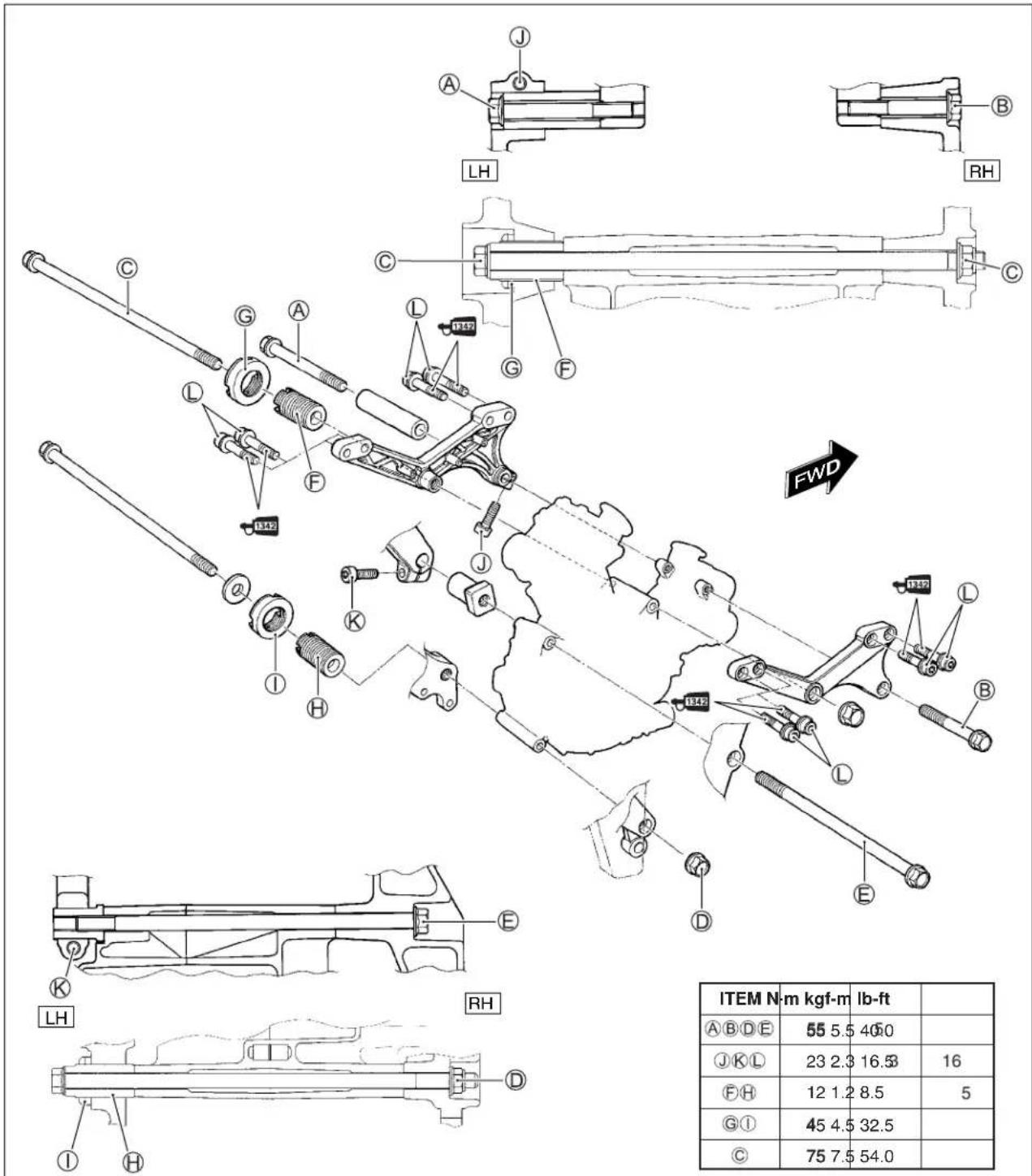
| ITEM N | m kgf-m | lb-ft | |
| A B D E | 55 5.5 | 46.0 | |
| J K L | 23 2.3 | 16.5 | 16 |
| F H | 12 1.2 | 8.5 | 5 |
| G I | 45 4.5 | 32.5 | |
| C | 75 7.5 | 54.0 |
FI SYSTEM
• ECM terminals have been change is as following.
- To inspect the sensors according to the FI malfunction codes, refer to the following. (DL1000 service manual 4-32 to 4-50)

09930-82720: Mode select switch
DL1000K3 model

DL1000K4 model
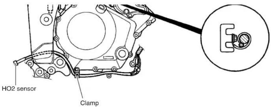
① Ignition coil #1
② Ignition coil #2
③ Ground
④ Tachometer
⑤ Fuel injector #1
⑥ Fuel injector #2
⑦ SOL
⑧ HO2 (OXH)
⑨ -
⑩ VCC
⑪ —
⑫ G+
⑬ Ground
⑭ THA
⑮ +B
⑯ PM
⑰ PA
⑱ CLT
⑲ TPS
⑳ MO+
②1 STA
⑳ MO-
②3 —
⑳ HO2 (OX)
⑳ Ground
②6 N+
⑳ -
⑳ VM
⑲ —
③0 N-
③1 GP
③2 FP
③3 AT
③4 E2
③5 Ground
③6 THW
③7 TECH
38
⑲ TS
④0 NT
④1 DON
④2 —
④3 —
④4 STPS
COMBINATION METER
REMOVAL AND DISASSEMBLY
- Disconnect the battery lead wire.
- Remove the combination meter panel.
- Remove the combination meter ①.
CAUTION
When disconnecting and connecting the combination meter coupler, make sure to turn OFF the ignition switch, or electronic parts may get damaged.
- Disassemble the combination meter as follows.
CAUTION
Do not attempt to disassemble the combination meter unit.

natural_image
Top-down view of a mechanical component with labeled parts (1), showing internal components and mounting holes (no text or symbols beyond labels)
① Combination meter cover
② Combination meter unit
INSPECTION
LED (LIGHT EMITTING DIODE)
Check that the LED lights immediately after turning the ignition switch on.
If the LED fails in operation, replace the combination meter unit with a new one after checking its wire harness/coupler.
STEPPING MOTOR
Check that the pointer calibrates itself immediately after turning the ignition switch on and stops at starting point.
If abnormal condition is found, replace the combination meter unit with a new one after checking its wire harness/coupler.

NOTE:
The pointer may not return to the proper position even turning the ignition switch on under low temperature condition. In that case, you can reset the pointer to the proper position by following the instruction below:
1) With the ADJ switch Ⓐ pressed, turn the ignition switch on.
2) Keep pushing the ADJ switch Ⓐ for 3 to 5 seconds.
3) Push the ADJ switch Ⓐ twice (within 1 second). → Reset
* Complete the operation within 10 seconds after the ignition switch has been turned on.

flowchart
graph TD
    A["Time Ignition switch ADJ switch"] --> B["OFF"]
    B --> C["0"]
    B --> D["3 sec"]
    B --> E["5 sec"]
    B --> F["10 sec"]
    B --> G["ON"]
    G --> H["PUSH"]
    H --> I["Release"]
    I --> J["Push"]
    I --> K["Push → Reset"]

Ⓐ ADJ SWITCH
Pointer will return to the starting point right after the completion of the operation. In the case of the pointer not returning to the proper position after doing above, replace the combination meter unit.
ODOMETER
The odometer indicates “----” when the odometer is faulty. Replace the combination meter unit with a new one.

TRIP METER
The trip meter indicates “----.-” when the trip meter is faulty. In case the odometer works normally, perform the trip meter reset. If the trip meter isn’t restored after above reset, replace the combination meter unit with a new one.

TRIP METER RESET PROCEDURE
- Turn the ignition "ON".
- Select the trip meter by pushing the SEL switch Ⓐ.
- Push the ADJ switch Ⓑ for 2 seconds.

INDICATORS
ENGINE COOLANT TEMPERATURE METER INSPECTION
- Disconnect the ECT sensor coupler ①.
CAUTION
When connecting and disconnecting the ECT sensor lead wire coupler, make sure to turn OFF the ignition switch, or electronic parts may get damaged.

natural_image
Close-up of a mechanical device interior showing internal components and a numbered annotation (1), no readable text or symbols present.- Connect the variable resistor Ⓐ between the terminals.
- Turn the ignition switch "ON".
- Check the display of engine coolant temperature meter as shown below. If any abnormality is found, replace the combination meter with a new one.
Ⓐ Variable resistor
⑧ ECT sensor
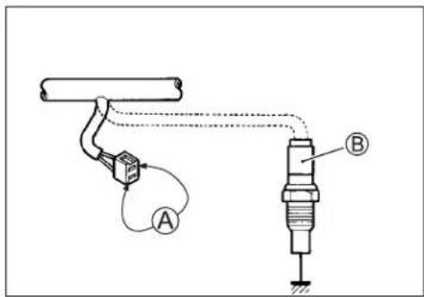
| Water temperature | 39 °C and below | 40 – 59 °C | 60 – 79 °C | 80 – 111 °C |
| Resistance | 1.148 kΩand more | 1.148 – 0.587 kΩ | 0.587 – 0.188 kΩ | 0.188 – 0.140 kΩ |
| Engine coolanttemperature meter |  |  |  |  |
| Water temperature | 112 – 119 °C | 120 °C and over | 122 °C and over | |
| Resistance | 0.140 – 0.116 kΩ | 0.116 kΩand less | 0.111 kΩand less | |
| Engine coolanttemperature meter |  |  |  | |
- Remove the fuel tank. (4-52)
- Remove the fuel pump. (4-55)
Measure the resistance at each fuel level gauge float position. If the resistance is incorrect, replace the fuel level gauge with a new one.
| Float position Resistance |
| A“F”(Full) Approx. 4 Ω |
| B“E”(Empty) Approx. 182 Ω |

09900-25008: Multi circuit tester set

Tester knob indication: Resistance (Ω)
• Install the fuel pump. (4-58)

natural_image
Mechanical device with cylindrical body and attached wires, no visible text or symbols
natural_image
Close-up of a mechanical component with labeled section A (no readable text or symbols)
natural_image
Close-up of a mechanical device with labeled component B (no readable text or symbols)
natural_image
Hand holding a small electrical socket connected to a multimeter (no text or symbols visible)FUEL LEVEL METER INSPECTION
- Remove the fuel tank left side cover.
-
Disconnect the fuel pump lead wire coupler.
-
Connect the each resistor between the Yellow/Black and Black/White lead wires at the wire harness.
- Turn the ignition switch "ON" position and wait for approx. 40 seconds.
Check the display of fuel meter as shown below, If any abnormality is found, replace the combination meter with a new one.
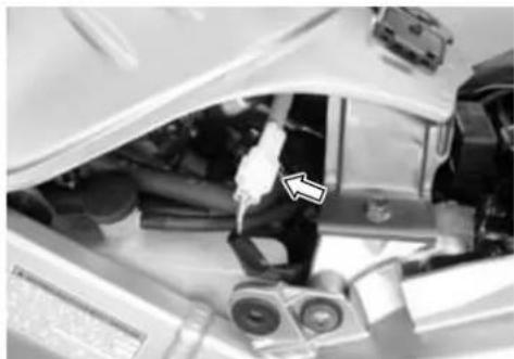
natural_image
Close-up of a car engine compartment with visible engine and dashboard components (no text or symbols)
natural_image
Close-up of a mechanical component with a hand holding a tool, showing no visible text or symbols.| Resistance | More than 167.0 Ω | 87.5 – 167.0 Ω | 50.0 – 87.5 Ω | 26.0 – 50.0 Ω | 6.5 – 26.0 Ω | 6.5 Ω and less | ||||||
| Fuel level meter |  |  |  |  |  |  | ||||||
WIRE HARNESS ROUTING
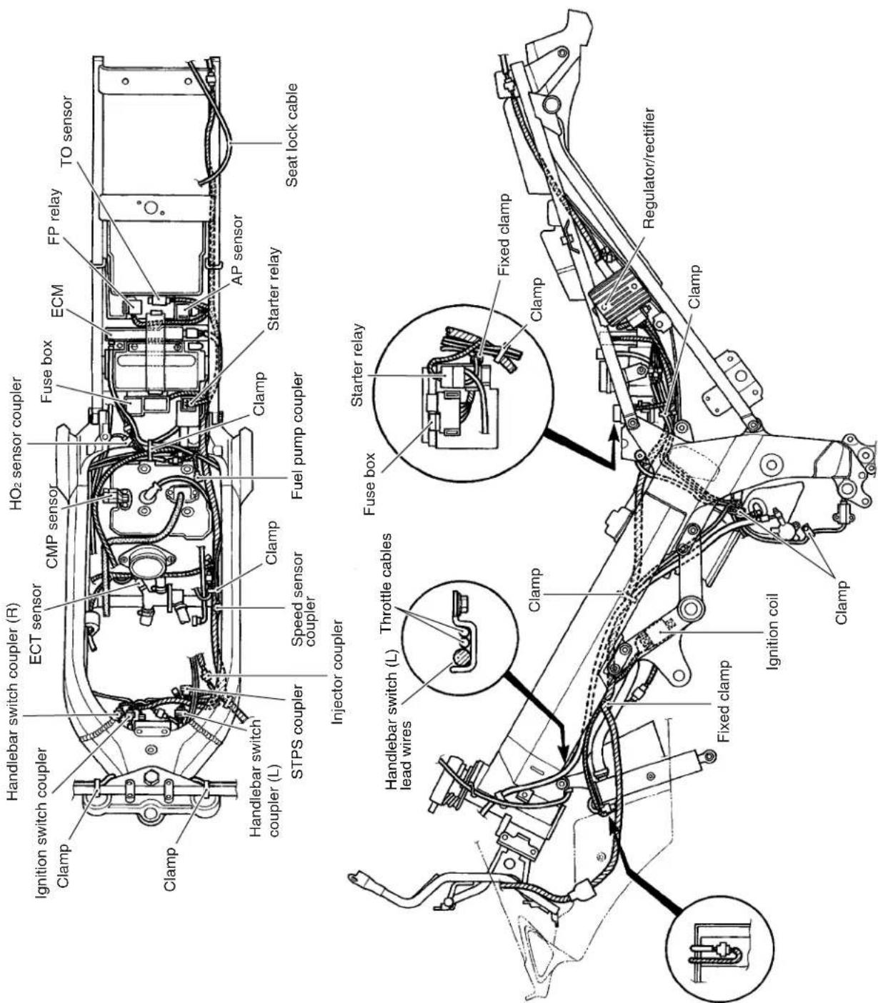


COWLING SETUP

① Screen
② Cowling brace
③ Combination meter panel
④ Cowling body
⑤ Right cowling
⑥ Left cowling
⑦ Left side cowling
⑧ Right side cowling
⑨ Inner cowling
⑩ Engine under cover
Ⓐ Cowling brace mounting bolt
U
| ITEM N·m kgf-m lb-ft | |||
| A | 35 3.5 | 25.5 | |
WIRING DIAGRAM
FI SYSTEM WIRING DIAGRAM

WIRING DIAGRAM
E-02, 19

flowchart
graph TD
    A["SP : SPEEDOMETER LIGHT"] --> B["UNITION SWITCH"]
    B --> C["ENGINE STOP SWITCH"]
    C --> D["FRONT SHAPE SWITCH"]
    D --> E["OIL PRESSOR SWITCH"]
    E --> F["BEAR BRAKE SWITCH"]
    F --> G["FUEL PUMP"]
    G --> H["AP SENSOR"]
    H --> I["ECM"]
    I --> J["BEAR TURN SIGNAL LIGHT (R)"]
    K["HEADLIGHT (R)"] --> L["FAIR MOTOR"]
    M["HEADLIGHT (L)"] --> N["FAIR MOTOR"]
    O["POSITION LIGHT (L)"] --> P["FAIR MOTOR"]
    Q["POSITION LIGHT (L)"] --> R["FAIR MOTOR"]
    S["FRONT TURN SIGNAL LIGHT (F)"] --> T["FAIR MOTOR"]
    U["RETURN SIGNAL LIGHT (L)"] --> V["FAIR MOTOR"]
    W["SPEEDOMETER"] --> X["HANDLEBAR SWITCH (R)"]
    X --> Y["UNITION SWITCH"]
    Z["LEFT ONER SWITCH"] --> AA["UNITION SWITCH"]
    AB["LEFT ONER SWITCH"] --> AC["UNITION SWITCH"]
    AD["LEFT ONER SWITCH"] --> AE["UNITION SWITCH"]
    AF["LEFT ONER SWITCH"] --> AG["UNITION SWITCH"]
    AH["LEFT ONER SWITCH"] --> AI["UNITION SWITCH"]
    AJ["LEFT ONER SWITCH"] --> AK["UNITION SWITCH"]
    AL["LEFT ONER SWITCH"] --> AM["UNITION SWITCH"]
    AN["LEFT ONER SWITCH"] --> AO["UNITION SWITCH"]
    AP["LEFT ONER SWITCH"] --> AQ["UNITION SWITCH"]
    AR["LEFT ONER SWITCH"] --> AS["UNITION SWITCH"]
    AT["LEFT ONER SWITCH"] --> AU["UNITION SWITCH"]
    AV["LEFT ONER SWITCH"] --> AW["UNITION SWITCH"]
    AX["LEFT ONER SWITCH"] --> AY["UNITION SWITCH"]
    AZ["LEFT ONER SWITCH"] --> BA["UNITION SWITCH"]
    BB["LEFT ONER SWITCH"] --> BC["UNITION SWITCH"]
    BD["LEFT ONER SWITCH"] --> BE["UNITION SWITCH"]
    BF["LEFT ONER SWITCH"] --> BG["UNITION SWITCH"]
    BH["LEFT ONER SWITCH"] --> BI["UNITION SWITCH"]
    BJ["LEFT ONER SWITCH"] --> BK["UNITION SWITCH"]
    BL["LEFT ONER SWITCH"] --> BLA["UNITION SWITCH"]
    BM["LEFT ONER SWITCH"] --> BN["UNITION SWITCH"]
    BO["LEFT ONER SWITCH"] --> BP["UNITION SWITCH"]
    BQ["LEFT ONER SWITCH"] --> BR["UNITION SWITCH"]
    BS["LEFT ONER SWITCH"] --> BT["UNITION SWITCH"]
    BU["LEFT ONER SWITCH"] --> BV["UNITION SWITCH"]
    BW["LEFT ONER SWITCH"] --> BX["UNITION SWITCH"]
    BY["LEFT ONER SWITCH"] --> BYA["UNITION SWITCH"]
    CA["LEFT ONER SWITCH"] --> CB["UNITION SWITCH"]
    CC["LEFT ONER SWITCH"] --> CD["UNITION SWITCH"]
    CE["LEFT ONER SWITCH"] --> CF["UNITION SWITCH"]
    CG["LEFT ONER SWITCH"] --> CH["UNITION SWITCH"]
    CI["LEFT ONER SWITCH"] --> CJ["UNITION SWITCH"]
    CK["LEFT ONER SWITCH"] --> CL["UNITION SWITCH"]
    CM["LEFT ONER SWITCH"] --> CN["UNITION SWITCH"]
    CO["LEFT ONER SWITCH"] --> CP["UNITION SWITCH"]
    CS["LEFT ONER SWITCH"] --> CSA["UNITION SWITCH"]
    CT["LEFT ONER SWITCH"] --> CU["UNITION SWITCH"]
    CV["LEFT ONER SWITCH"] --> CW["UNITION SWITCH"]
    CX["LEFT ONER SWITCH"] --> CY["UNITION SWITCH"]
    CZ["LEFT ONER SWITCH"] --> CZA["UNITION SWITCH"]
    DA["LEFT ONER SWITCH"] --> DB["UNITION SWITCH"]
    DC["LEFT ONER SWITCH"] --> DEA["UNITION SWITCH"]
    DF["LEFT ONER SWITCH"] --> DFAB["UNITION SWITCH"]
    DG["LEFT ONER SWITCH"] --> DHX["XH/HEV"]
    DI["XH/HEV"] --> DJ["XH/HEV"]
    DK["XH/HEV"] --> DL["XH/HEV"]
    DV["XH/HEV"] --> DW["XH/HEV"]
E-03, 28, 33
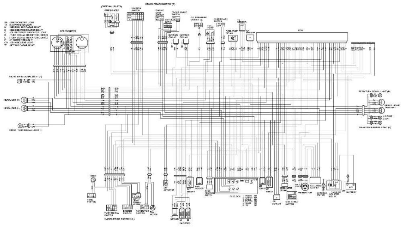
flowchart
graph TD
    A["SP - SPEEDOMETER LIGHT"] --> B["HEADLATOR SWITCH (R)"]
    C["SP - TURB SIGNAL INDICATOR LIGHT"] --> D["HEADLATOR SWITCH (L)"]
    E["SP - FLUIDORATION LIGHT"] --> F["HEADLATOR SWITCH (L)"]
    G["SP - RCT INDICATOR LIGHT"] --> H["HEADLATOR SWITCH (L)"]
    I["HEADLIGHT (R)"] --> J["HEADLATOR SWITCH (L)"]
    K["HEADLIGHT (L)"] --> L["HEADLATOR SWITCH (L)"]
    M["HEADLATOR SWITCH (L)"] --> N["HEADLATOR SWITCH (L)"]
    O["HEADLATOR SWITCH (L)"] --> P["HEADLATOR SWITCH (L)"]
    Q["HEADLATOR SWITCH (L)"] --> R["HEADLATOR SWITCH (L)"]
    S["HEADLATOR SWITCH (L)"] --> T["HEADLATOR SWITCH (L)"]
    U["HEADLATOR SWITCH (L)"] --> V["HEADLATOR SWITCH (L)"]
    W["HEADLATOR SWITCH (L)"] --> X["HEADLATOR SWITCH (L)"]
    Y["HEADLATOR SWITCH (L)"] --> Z["HEADLATOR SWITCH (L)"]
    AA["HEADLATOR SWITCH (L)"] --> AB["HEADLATOR SWITCH (L)"]
    AC["HEADLATOR SWITCH (L)"] --> AD["HEADLATOR SWITCH (L)"]
    AE["HEADLATOR SWITCH (L)"] --> AF["HEADLATOR SWITCH (L)"]
    AG["HEADLATOR SWITCH (L)"] --> AH["HEADLATOR SWITCH (L)"]
    AI["HEADLATOR SWITCH (L)"] --> AJ["HEADLATOR SWITCH (L)"]
    AK["HEADLATOR SWITCH (L)"] --> AL["HEADLATOR SWITCH (L)"]
    AM["HEADLATOR SWITCH (L)"] --> AN["HEADLATOR SWITCH (L)"]
    AO["HEADLATOR SWITCH (L)"] --> AP["HEADLATOR SWITCH (L)"]
    AQ["HEADLATOR SWITCH (L)"] --> AR["HEADLATOR SWITCH (L)"]
    AS["HEADLATOR SWITCH (L)"] --> AT["HEADLATOR SWITCH (L)"]
    AU["HEADLATOR SWITCH (L)"] --> AV["HEADLATOR SWITCH (L)"]
    AW["HEADLATOR SWITCH (L)"] --> AX["HEADLATOR SWITCH (L)"]
    AY["HEADLIGHT (R)"] --> AZ["TURB SIGNAL SWITCH"]
    BA["HEADLIGHT (L)"] --> BB["TURB SIGNAL SWITCH"]
    BC["HEADLIGHT (R)"] --> BD["TURB SIGNAL SWITCH"]
    BE["HEADLIGHT (L)"] --> BF["TURB SIGNAL SWITCH"]
    BG["HEADLIGHT (R)"] --> BH["TURB SIGNAL SWITCH"]
    BI["HEADLIGHT (L)"] --> BJ["TURB SIGNAL SWITCH"]
    BK["HEADLIGHT (R)"] --> BL["TURB SIGNAL SWITCH"]
    BM["HEADLIGHT (L)"] --> BN["TURB SIGNAL SWITCH"]
    BO["HEADLIGHT (R)"] --> BR["TURB SIGNAL SWITCH"]
    BS["HEADLIGHT (L)"] --> BT["TURB SIGNAL SWITCH"]
    BU["HEADLIGHT (R)"] --> BV["TURB SIGNAL SWITCH"]
    BW["HEADLIGHT (L)"] --> BX["TURB SIGNAL SWITCH"]
    BY["HEADLIGHT (R)"] --> CA["TURB SIGNAL SWITCH"]
    CB["HEADLIGHT (L)"] --> CC["TURB SIGNAL SWITCH"]
    CD["HEADLIGHT (R)"] --> CE["TURB SIGNAL SWITCH"]
    CF["HEADLIGHT (L)"] --> CG["TURB SIGNAL SWITCH"]
    DH["HEADLIGHT (R)"] --> DI["TURB SIGNAL SWITCH"]
    DJ["HEADLIGHT (L)"] --> DE["TURB SIGNAL SWITCH"]
    DF["HEADLIGHT (R)"] --> DG["TURB SIGNAL SWITCH"]
    DHX["TURB SIGNAL SWITCH"] --> DHX
    DHX --> DHX
    DHX --> DHX
    DHX --> DHX
    DHX --> DHX
    DHX --> DHX
    DHX --> DHX
    DHX --> DHX
    DHX --> DHX
    DHX --> DHX
    DHX --> DHX
    DHX --> DHX
    DHX --> DHX
    DHX --> DHX
    DHX --> DHX
    DHX --> DRH
    DHX --> DRH
    DHX --> DRH
    DHX --> DRH
    DHX --> DRH
    DHX --> DRH
    DHX --> DRH
    DHX --> DRH
    DHX --> DRH
    DHX --> DRH
    DHX --> DRH
    DHX --> DRH
    DHX --> DRH
    DHX --> DRH
    DHX --> DRH

    style SP fill:#f9f,stroke:#333
    style SP fill:#ccf,stroke:#333
    style SP fill:#cfc,stroke:#333
    style SP fill:#fcc,stroke:#333

    subgraph Handlebar Switches
        B1["(OPTIONAL PARTS) ONF HEATER"]
        B2["IQRTATION SWITCH"]
        B3["EQUIPE STOP"]
        B4["FROAT BRANE SWITCH"]
        B5["COLI PROCESIVE SWITCH"]
        B6["CUEL SPRING SWITCH"]
        B7["FUEL SPRING SWITCH"]
        B8["FUEL SPRING RELAY"]
        B9["FUEL SPRING RELAY"]
        B10["FUEL SPRING RELAY"]
        B11["FUEL SPRING RELAY"]
        B12["FUEL SPRING RELAY"]
        B13["FUEL SPRING RELAY"]
        B14["FUEL SPRING RELAY"]
        B15["FUEL SPRING RELAY"]
        B16["FUEL SPRING RELAY"]
        B17["FUEL SPRING RELAY"]
        B18["FUEL SPRING RELAY"]
        B19["FUEL SPRING RELAY"]
        B20["FUEL SPRING RELAY"]
        B21["FUEL SPRING RELAY"]
        B22["FUEL SPRING RELAY"]
        B23["FUEL SPRING RELAY"]
        B24["FUEL SPRING RELAY"]
        B25["FUEL SPRING RELAY"]
        B26["FUEL SPRING RELAY"]
        B27["FUEL SPRING RELAY"]
        B28["FUEL SPRING RELAY"]
        B29["FUEL SPRING RELAY"]
        B30["FUEL SPRING RELAY"]
        B31["FUEL SPRING RELAY"]
        B32["FUEL SPRING RELAY"]
        B33["FUEL SPRING RELAY"]
        B34["FUEL SPRING RELAY"]
        B35["FUEL SPRING RELAY"]
        B36["FUEL SPRING RELAY"]
        B37["FUEL SPRING RELAY"]
        B38["FUEL SPRING RELAY"]
        B39["FUEL SPRING RELAY"]
        B40["FUEL SPRING RELAY"]
        B41["FUEL SPRING RELAY"]
        B42["FUEL SPRING RELAY"]
        B43["FUEL SPRING RELAY"]
        B44["FUEL SPRING RELAY"]
        B45["FUEL SPRING RELAY"]
        B46["FUEL SPRING RELAY"]
        B47["FUEL SPRING RELAY"]
        B48["FUEL SPRING RELAY"]
        B49["FUEL SPRING RELAY"]
        B50["FUEL SPRING RELAY"]
        B51["FUEL SPRING RELAY"]
        B52["FUEL SPRING RELAY"]
        B53["FUEL SPRING RELAY"]
        B54["FUEL SPRING RELAY"]
        B55["FUEL SPRING RELAY"]
        B56["FUEL SPRING RELAY"]
        B57["FUEL SPRING RELAY"]
        B58["FUEL SPRING RELAY"]
        B59["FUEL SPRING RELAY"]
        B60["FUEL SPRING RELAY"]
        B61["FUEL SPRING RELAY"]
        B62["FUEL SPRING RELAY"]
        B63["FUEL SPRING RELAY"]
        B64["FUEL SPRING RELAY"]
        B65["FUEL SPRING RELAY"]
        B66["FUEL SPRING RELAY"]
        B67["FUEL SPRING RELAY"]
        B68["FUEL SPRING RELAY"]
        B69["FUEL SPRING RELAY"]
        B70["FUEL SPRING RELAY"]
        B71["FUEL SPRING RELAY"]
        B72["FUEL SPRING RELAY"]
        B73["FUEL SPRING RELAY"]
        B74["FUEL SPRING RELAY"]
        B75["FUEL SPRING RELAY"]
        B76["FUEL SPRING RELAY"]
        B77["FUEL SPRING RELAY"]
        B78["FUEL SPRING RELAY"]
        B79["FUEL SPRING RELAY"]
        B80["FUEL SPRING RELAY"]
        B81["FUEL SPRING RELAY"]
        B82["FUEL SPRING RELAY"]
        B83["FUEL SPRING RELAY"]
        B84["FUEL SPRING RELAY"]
        B85["FUEL SPRING RELAY"]
        B86["FUEL SPRING RELAY"]
        B87["FUEL SPRING RELAY"]
        B88["FUEL SPRING RELAY"]
        B89["FUEL SPRING RELAY"]
        B90["FUEL SPRING RELAY"]
        B91["FUEL SPRING RELAY"]
        B92["FUEL SPRING RELAY"]
        B93["FUEL SPRING RELAY"]
        B94["FUEL SPRING RELAY"]
        B95["FUEL SPRING RELAY"]
        B96["FUEL SPRING RELAY"]
        B97["FUEL SPRING RELAY"]
        B98["FUEL SPRING RELAY"]
        B99["GND"] --> 1
    end

    subgraph Rear Turn Signal Light
        AD["Rear Turn Signal Light (R)"]
            AE["Rear Turn Signal Light TALLIGHT"] --> AF["LDC/REF. LIGHT"] --> AG["LDC/REF. LIGHT"] --> AH["LDC/REF. LIGHT"] --> AI["LDC/REF. LIGHT"] --> AJ["LDC/REF. LIGHT"] --> AK["LDC/REF. LIGHT"] --> AL["LDC/REF. LIGHT"] --> AM["LDC/REF. LIGHT"] --> AN["LDC/REF. LIGHT"] --> AO["LDC/REF. LIGHT"] --> AP["LDC/REF. LIGHT"] --> AQ["LDC/REF. LIGHT"] --> AR["LDC/REF. LIGHT"] --> AS["LDC/REF. LIGHT"] --> AT["LDC/REF. LIGHT"] --> AU["LDC/REF. LIGHT"] --> AV["LDC/REF. LIGHT"] --> AW["LDC/REF. LIGHT"] --> AX["LDC/REF. LIGHT"] --> AY["LDC/REF. LIGHT"] --> AZ["LDC/REF. LIGHT"] --> BA["LDC/REF. LIGHT"] --> BB["LDC/REF. LIGHT"] --> BC["LDC/REF. LIGHT"] --> BD["LDC/REF. LIGHT"] --> BE["LDC/REF. LIGHT"] --> BF["LDC/REF. LIGHT"] --> BG["LDC/REF. LIGHT"] --> BH["LDC/REF. LIGHT"] --> BI["LDC/REF. LIGHT"] --> BJ["LDC/REF. LIGHT"] --> BK["LDC/REF. LIGHT"] --> BL["LDC/REF. LIGHT"] --> BM["LDC/REF. LIGHT"] --> BN["LDC/REF. LIGHT"] --> BO["LDC/REF. LIGHT"] --> BP["LDC/REF. LIGHT"] --> BPLO["LDC/REF. LIGHT"] --> BPBE["LDC/REF. LIGHT"] --> BPBELO["LDC/REF. LIGHT"] --> BPBELOLO["LDC/REF. LIGHT"] --> BPBELOLO["Battery"]

flowchart
graph TD
    A["SP. SPEEDOMETER LIGHT"] --> B["STOCKEDETER"]
    B --> C["OPTIONAL PATTS: GRP HEATER"]
    C --> D["DRAGON STOP SWITCH"]
    D --> E["FRONT BRANE SWITCH"]
    E --> F["OL PROCEDURE SWITCH"]
    F --> G["MAX MOUNT SWITCH"]
    G --> H["TO SENSOR"]
    H --> I["AP MOUNT"]
    I --> J["ECU"]
    J --> K["POWER TURN SIGNAL LIGHT (R)"]
    K --> L["DRAGON LIMIT TAILLIGHT"]
    L --> M["LEAD ICE LIGHT"]
    M --> N["PION TURN SIGNAL LIGHT (L)"]

    subgraph MODELS
        O["HEAD TURN SIGNAL SWITCH (L)"] --> P["POWER SWITCH"]
        Q["TRIN SIGNAL SWITCH"] --> R["TAIN MOTOR SWITCH"]
        S["SHORT CHANNEL SWITCH"] --> T["FUSIC DOG"]
        U["SOODUCT"] --> V["AUX SWITCH"]
        W["ACV"] --> X["AUX SWITCH"]
        Y["ACV"] --> Z["AUX SWITCH"]
        AA["ACV"] --> AB["AUX SWITCH"]
        AC["ACV"] --> AD["AUX SWITCH"]
        AE["ACV"] --> AF["AUX SWITCH"]
        AG["ACV"] --> AH["AUX SWITCH"]
        AI["ACV"] --> AJ["AUX SWITCH"]
        AK["ACV"] --> AL["AUX SWITCH"]
        AM["ACV"] --> AN["AUX SWITCH"]
        AO["ACV"] --> AP["AUX SWITCH"]
        AQ["ACV"] --> AR["AUX SWITCH"]
        AS["ACV"] --> AT["AUX SWITCH"]
        AU["ACV"] --> AV["AUX SWITCH"]
        AW["ACV"] --> AX["AUX SWITCH"]
        AY["ACV"] --> AZ["AUX SWITCH"]
        BA["ACV"] --> BB["AUX SWITCH"]
        BC["ACV"] --> BD["AUX SWITCH"]
        BE["ACV"] --> BF["AUX SWITCH"]
        BG["ACV"] --> BG["AUX SWITCH"]
        BH["ACV"] --> BI["AUX SWITCH"]
        BJ["ACV"] --> BJ["AUX SWITCH"]
        BK["ACV"] --> BL["AUX SWITCH"]
        BM["ACV"] --> BN["AUX SWITCH"]
        BO["ACV"] --> BN["AUX SWITCH"]
        BP["ACV"] --> BQ["AUX SWITCH"]
        BR["ACV"] --> BS["AUX SWITCH"]
        BT["ACV"] --> BT["AUX SWITCH"]
        BU["ACV"] --> BV["AUX SWITCH"]
        BW["ACV"] --> BWA["AUX SWITCH"]
        BX["ACV"] --> BYA["AUX SWITCH"]
        BZ["ACV"] --> BZA["AUX SWITCH"]
        CA["ACV"] --> CAA["AUX SWITCH"]
        CB["ACV"] --> CBA["AUX SWITCH"]
        CC["ACV"] --> CCB["AUX SWITCH"]
        DC["ACV"] --> DCB["AUX SWITCH"]
        DD["ACV"] --> DDAB["AUX SWITCH"]
        DB["ACV"] --> DBA["AUX SWITCH"]
        DCB --> DCB
    end
MODEL APPLICATION
| Year Model Beginning Frame No. | ||
| 2004 | LV1000-A1 | JSKBS112100100001 or JSKBS112200100001 |


- Motorcycle Service Manual
- Motorcycle Service Manual Supplement
- Foreword
- How to Use This Manual
- WARNING
- CAUTION
- NOTE
- Symbol
- General Information
- Contents
- GENERAL PRECAUTIONS
- COUNTRY AND AREA CODES
- Periodic Maintenance
- PERIODIC MAINTENANCE SCHEDULE
- VALVE CLEARANCE ADJUSTMENT CHART INLET VALVE
- VALVE CLEARANCE ADJUSTMENT CHART EXHAUST VALVE
- Engine
- FI System
- Cooling System
- Chassis
- Electrical System
- Servicing Information
- Emission Control Information
- Base Manual
- Suzuki DL1000
- SUZUKI MOTOR CORPORATION
- TO LOCATE WHAT YOU ARE LOOKING FOR:
- COMPONENT PARTS AND WORK TO BE DONE
- ABBREVIATIONS USED IN THIS MANUAL
- A
- B
- C
- D
- F
- G
- H
- |
- L
- M
- N
- 0
- P
- R
- s
- T
- V
- WARNING/CAUTION/NOTE
- NOTE:
- SUZUKI DL1000K2 ('02-MODEL)
- SERIAL NUMBER LOCATION
- FUEL, OIL AND ENGINE COOLANT RECOMMENDATION FUEL (FOR CANADIAN MODEL)
- FUEL (FOR OTHER COUNTRIES)
- ENGINE OIL
- BRAKE FLUID
- FRONT FORK OIL
- ENGINE COOLANT
- WATER FOR MIXING
- ANTI-FREEZE/ENGINE COOLANT
- LIQUID AMOUNT OF WATER/ENGINE COOLANT
- BREAK-IN PROCEDURES
- CYLINDER IDENTIFICATION
- INFORMATION LABELS
- SPECIFICATIONS
- DIMENSIONS AND DRY MASS
- DRIVE TRAIN
- ELECTRICAL
- CAPACITIES
- LUBRICATION POINTS
- MAINTENANCE AND TUNE-UP PROCEDURES
- AIR CLEANER
- SPARK PLUG
- NO.1 (FRONT) SPARK PLUG REMOVAL
- NO.2 (REAR) SPARK PLUG REMOVAL
- HEAT RANGE
- CARBON DEPOSIT
- SPARK PLUG GAP
- ELECTRODES CONDITION
- SPARK PLUG AND PLUG CAP INSTALLATION
- TAPPET CLEARANCE
- 09900-20803: Thickness gauge
- TAPPET CLEARANCE ADJUSTMENT
- (EXHAUST SIDE)
- FUEL HOSE
- ENGINE OIL AND OIL FILTER
- (ENGINE OIL)
- (OIL FILTER)
- ENGINE OIL REPLACEMENT
- OIL FILTER REPLACEMENT
- 09915-40610: Oil filter wrench
- DATA Engine oil capacity
- ENGINE IDLE SPEED
- THROTTLE CABLE PLAY
- MINOR ADJUSTMENT
- MAJOR ADJUSTMENT
- DATA Throttle cable play Ⓐ: 2.0 – 4.0 mm (0.08 – 0.16 in)
- THROTTLE VALVE SYNCHRONIZATION
- PAIR (AIR SUPPLY) SYSTEM
- CLUTCH
- CLUTCH FLUID LEVEL
- BLEEDING AIR FROM THE CLUTCH FLUID CIRCUIT
- ENGINE COOLANT LEVEL CHECK
- ENGINE COOLANT CHANGE
- AIR BLEEDING THE ENGINE COOLANT CIRCUIT
- Air bleeder bolt: 13 N·m (1.3 kgf-m, 9.5 lb-ft)
- RADIATOR HOSES
- DRIVE CHAIN
- CHECKING
- DATA
- Drive chain 20-pitch length
- Service Limit: 319.4 mm (12.6 in)
- ADJUSTING
- CLEANING AND LUBRICATING
- BRAKE
- (BRAKE)
- BRAKE PADS
- BRAKE PEDAL HEIGHT
- BRAKE LIGHT SWITCH
- AIR BLEEDING THE BRAKE FLUID CIRCUIT
- Air bleeder valve: 7.5 N·m (0.75 kgf-m, 5.5 lb-ft)
- TIRE
- TIRE TREAD CONDITION
- TIRE PRESSURE
- TIRE TYPE
- STEERING
- FRONT FORK
- REAR SUSPENSION
- EXHAUST PIPE BOLT
- CHASSIS BOLT AND NUT
- COMPRESSION PRESSURE CHECK
- Low compression pressure can indicate any of the following conditions:
- Overhaul the engine in the following cases:
- COMPRESSION TEST PROCEDURE
- OIL PRESSURE CHECK
- LOW OIL PRESSURE
- HIGH OIL PRESSURE
- OIL PRESSURE TEST PROCEDURE
- ENGINE COMPONENTS REMOVABLE WITH ENGINE IN PLACE
- ENGINE REMOVAL AND INSTALLATION
- ENGINE REMOVAL
- ENGINE INSTALLATION
- Engine oil capacity
- ENGINE DISASSEMBLY ENGINE TOP SIDE
- FRONT CYLINDER HEAD COVER
- FRONT CYLINDER CAMSHAFT
- FRONT CAM CHAIN TENSION ADJUSTER
- FRONT CYLINDER HEAD
- STARTER MOTOR
- FRONT CYLINDER
- FRONT PISTON
- REAR CYLINDER HEAD COVER
- REAR CYLINDER CAMSHAFT
- REAR CAM CHAIN TENSION ADJUSTER
- REAR CYLINDER HEAD
- REAR CYLINDER
- REAR PISTON
- ENGINE BOTTOM SIDE
- OIL FILTER
- CLUTCH COVER
- GEAR POSITION SWITCH
- OIL SUMP FILTER
- OIL PUMP
- CAM DRIVE IDLE GEAR/SPROCKET
- PRIMARY DRIVE GEAR
- GENENRATOR ROTOR
- GEARSHIFT
- 09920-13120: Crankcase separating tool
- ENGINE COMPONENTS INSPECTION AND SERVICING CYLINDER HEAD COVER
- INSPECTION
- REASSEMBLY
- CAMSHAFT/CYLINDER HEAD
- CAMSHAFT
- CAM WEAR
- CAMSHAFT JOURNAL WEAR
- CAMSHAFT RUNOUT
- CAM GEAR AND AUTOMATIC-DECOMP.
- CAM CHAIN TENSION ADJUSTER
- CAM CHAIN GUIDE AND CAM CHAIN TENSIONER
- CYLINDER HEAD
- CYLINDER HEAD DISTORTION
- VALVE STEM RUNOUT
- VALVE HEAD RADIAL RUNOUT
- VALVE FACE WEAR
- VALVE STEM DEFLECTION
- VALVE STEM WEAR
- VALVE GUIDE SERVICING
- VALVE SEAT WIDTH
- VALVE SEAT SERVICING
- VALVE SPRING
- CAM DRIVE IDLE GEAR/SPROCKET THRUST CLEARANCE
- 09900-20205: Micrometer (0 - 25 mm)
- CYLINDER HEAD REASSEMBLY
- 09916-44910: Valve guide remover/installer
- MOLYBDENUM OIL
- INTAKE PIPE/WATER UNION
- CYLINDER/PISTON INSPECTION CYLINDER DISTORTION
- CYLINDER BORE
- PISTON DIAMETER
- PISTON-TO-CYLINDER CLEARANCE
- PISTON RING TO GROOVE CLEARANCE
- PISTON RING FREE END GAP AND PISTON RING END GAP
- PISTON PIN AND PIN BORE
- CONROD/CRANKSHAFT
- CONROD SMALL END I.D.
- CONROD BIG END SIDE CLEARANCE
- CONROD-CRANK PIN BEARING INSPECTION
- CONROD-CRANK PIN BEARING SELECTION
- Conrod big end oil clearance
- BEARING ASSEMBLY
- CLUTCH DRIVE PLATES
- CLUTCH DRIVEN PLATES
- CLUTCH SPRING FREE LENGTH
- CLUTCH BEARING
- TRANSMISSION
- CONSTRUCTION
- DISASSEMBLY
- Countershaft
- Driveshaft
- GEARSHIFT FORK
- GEARSHIFT FORK TO GROOVE CLEARANCE
- PRIMARY DRIVE GEAR INSPECTION
- PRIMARY DRIVE GEAR DISASSEMBLY
- 09900-06107: Snap ring pliers
- PRIMARY DRIVE GEAR REASSEMBLY
- STARTER TORQUE LIMITER
- STARTER TORQUE LIMITER INSPECTION
- STARTER CLUTCH
- GEARSHIFT SHAFT/GEARSHIFT ARM DISASSEMBLY
- GEARSHIFT SHAFT/GEARSHIFT ARM INSPECTION
- RETURN SPRINGS INSPECTION
- GEARSHIFT SHAFT/GEARSHIFT ARM REASSEMBLY
- CRANKCASE
- OIL PRESSURE REGULATOR
- OIL PRESSURE SWITCH
- OIL JET
- BEARING/OIL SEAL
- CRANKCASE-CRANKSHAFT BEARING CRANKCASE-CRANKSHAFT BEARING INSPECTION
- CRANKCASE-CRANKSHAFT BEARING SELECTION
- CRANKSHAFT JOURNAL BEARING REPLACEMENT
- 09913-60230: Journal bearing remover/installer
- GENERATOR COVER
- REPLACEMENT
- OIL SEPARATER
- GEARSHIFT COVER
- OIL SEAL INSPECTION
- OIL SEAL REPLACEMENT
- ENGINE REASSEMBLY
- CRANKSHAFT
- GENERATOR ROTOR
- DRIVEN PLATE:
- DRIVE PLATE:
- ENGINE TOP SIDE
- PISTON
- CYLINDER
- Cylinder head bolt (M10):
- Cylinder head bolt (M10): Initial 25 N·m
- FRONT CAM DRIVE IDLE GEAR/SPROCKET
- Cam drive idle gear/sprocket shaft:
- REAR CAM DRIVE IDLE GEAR/SPROCKET
- Cam chain tension adjuster mounting bolt:
- Cam chain tension adjuster bolt (Rear):
- NO.1 (FRONT) CAMSHAFTS
- Camshaft journal holder bolt: 10 N·m (1.0 kgf·m, 7.0 lb·ft)
- CYLINDER HEAD COVER
- PRECAUTIONS IN SERVICING
- CONNECTOR/COUPLER
- FUSE
- ECM/VARIOUS SENSORS
- ELECTRICAL CIRCUIT INSPECTION PROCEDURE
- OPEN CIRCUIT CHECK
- Continuity check
- VOLTAGE CHECK
- Voltage Between:
- SHORT CIRCUIT CHECK (WIRE HARNESS TO GROUND)
- USING TESTERS
- Using the tester
- 09900-25008: Multi-circuit tester
- FI SYSTEM TECHNICAL FEATURES INJECTION TIME (INJECTION VOLUME)
- COMPENSATION OF INJECTION TIME (VOLUME)
- INJECTION STOP CONTROL
- FUEL PUMP
- FUEL PRESSURE REGULATOR
- FUEL INJECTOR
- ECM (FI CONTROL UNIT)
- INJECTION TIMING
- SENSORS
- INTAKE AIR PRESSURE SENSOR (IAP SENSOR)
- THROTTLE POSITION SENSOR (TP SENSOR)
- CRANKSHAFT POSITION SENSOR (CKP SENSOR)
- CAMSHAFT POSITION SENSOR (CMP SENSOR)
- INTAKE AIR TEMPERATURE SENSOR (IAT SENSOR)
- ENGINE COOLANT TEMPERATURE SENSOR (ECT SENSOR)
- ATMOSPHERIC PRESSURE SENSOR (AP SENSOR)
- TIP OVER SENSOR (TO SENSOR)
- SECONDARY THROTTLE POSITION SENSOR (STP SEN- SOR)
- FI SYSTEM WIRING DIAGRAM
- SELF-DIAGNOSIS FUNCTION
- DEALER MODE
- TPS ADJUSTMENT
- FAIL-SAFE FUNCTION
- FI SYSTEM TROUBLESHOOTING CUSTOMER COMPLAINT ANALYSIS
- SELF-DIAGNOSTIC PROCEDURES
- SELF-DIAGNOSIS RESET PROCEDURE
- "C11" CMP SENSOR CIRCUIT MALFUNCTION
- "C12" CKP SENSOR CIRCUIT MALFUNCTION
- "C13" IAP SENSOR CIRCUIT MALFUNCTION
- 3
- "C14" TP SENSOR CIRCUIT MALFUNCTION
- "C15" ECT SENSOR CIRCUIT MALFUNCTION
- "C21" IAT SENSOR CIRCUIT MALFUNCTION
- "C22" AP SENSOR CIRCUIT MALFUNCTION
- "C23" TO SENSOR CIRCUIT MALFUNCTION
- "C24" or "C25" IGNITION SYSTEM MALFUNCTION
- "C29" STP SENSOR CIRCUIT MALFUNCTION
- "C31" GEAR POSITION (GP) SWITCH CIRCUIT MALFUNCTION
- "C32" or "C33" FUEL INJECTION MALFUNCTION
- "C41" FP RELAY CIRCUIT MALFUNCTION
- "C42" IG SWITCH CIRCUIT MALFUNCTION
- Turn the ignition switch OFF.
- DATA Heater voltage: Battery voltage
- Turn the ignition switch OFF.
- DATA H 0 sensor resistance: 4 – 5 Ω (at 23 °C/73.4 °F)
- FUEL SYSTEM
- FUEL TANK LIFT-UP
- FUEL TANK REMOVAL
- FUEL TANK INSTALLATION
- FUEL PRESSURE INSPECTION
- Fuel pressure: Approx. 300 kPa (3.0 kgf/cm², 43 psi)
- FUEL PUMP INSPECTION
- FUEL DISCHARGE AMOUNT INSPECTION
- FUEL PUMP RELAY INSPECTION
- FUEL PUMP AND FUEL FILTER REMOVAL
- FUEL MESH FILTER INSPECTION AND CLEANING
- FUEL PUMP AND FUEL MESH FILTER INSTALLATION
- Fuel pump mounting bolt: 10 N·m (1.0 kgf·m, 7.3 lb·ft)
- THROTTLE BODY REMOVAL
- THROTTLE BODY DISASSEMBLY
- 09930-11950: Torx wrench
- THROTTLE BODY CLEANING
- THROTTLE BODY REASSEMBLY
- 99000-32050: THREAD LOCK "1342"
- STVA cover nut: 2.0 N·m (0.2 kgf·m, 1.5 lb·ft)
- Fast idle cam mounting nut: 4.0 N·m (0.4 kgf-m, 3.0 lb-ft)
- Throttle body link plate bolt: 5 N·m (0.5 kgf-m, 3.7 lb-ft)
- Replace the cushion seal with a new one.
- Replace the dust seal and O-ring with the new ones. Never turn the injector while pushing it.
- Fuel delivery pipe mounting screw:
- 99000-25030: SUZUKI SUPER GREASE "A" (USA)
- STP sensor mounting screw: 3.5 N·m(0.35 kgf·m, 2.5 lb·ft)
- STP SENSOR ADJUSTMENT
- THROTTLE BODY INSTALLATION
- TP SENSOR ADJUSTMENT
- 09930-82710: Mode select switch
- TP sensor mounting screw: 3.5 N·m (0.35 kgf·m, 2.5 lb·ft)
- FUEL INJECTOR INSPECTION
- FUEL INJECTOR REMOVAL
- FUEL INJECTOR INSTALLATION
- FAST IDLE INSPECTION
- FAST IDLE ADJUTMENT
- 09913-13121: Vacuum balancer gauge
- 09940-40220: Fuel pressure gauge hose attachment
- For vacuum balancer gauge (09913-13121)
- THROTTLE CABLE ADJUSTMENT
- SENSOR
- IAP SENSOR INSPECTION
- IAP SENSOR REMOVAL/INSTALLATION
- TP SENSOR INSPECTION
- TP SENSOR REMOVAL/INSTALLATION
- STP SENSOR INSPECTION
- STP SENSOR REMOVAL/INSTALLATION
- CKP SENSOR INSPECTION
- CKP SENSOR REMOVAL/INSTALLATION
- CMP SENSOR INSPECTION
- CMP SENSOR REMOVAL/INSTALLATION
- IAT SENSOR INSPECTION
- IAT SENSOR REMOVAL/INSTALLATION
- ECT SENSOR INSPECTION
- ECT SENSOR REMOVAL/INSTALLATION
- AP SENSOR INSPECTION
- AP SENSOR REMOVAL/INSTALLATION
- TO SENSOR INSPECTION
- TO SENSOR REMOVAL/INSTALLATION
- HO2 SENSOR INSPECTION
- HO2 SENSOR REMOVAL/INSTALLATION
- COOLING AND LUBRICATION SYSTEM
- COOLING CIRCUIT
- COOLING CIRCUIT INSPECTION
- RADIATOR
- REMOVAL
- INSPECTION AND CLEANING
- INSTALLATION
- Cooling fan/horn mounting bolt:
- Cooling fan thermo-switch: 17 N·m (1.7 kgf-m, 12.5 lb-ft)
- RADIATOR RESERVOIR TANK REMOVAL/INSTALLATION
- RADIATOR CAP INSPECTION
- Radiator cap valve opening pressure
- WATER HOSE
- COOLING FAN
- Cooling fan motor mounting bolt:
- COOLING FAN THERMO-SWITCH
- ENGINE COOLANT TEMPERATURE SENSOR
- THERMOSTAT
- Thermostat valve opening temperature
- Standard: Approx. 88 °C (190 °F)
- Thermostat valve lift
- Standard: Over 8.0 mm at 100 °C (Over 0.31 in at 212 °F)
- WATER PUMP
- REMOVAL AND DISASSEMBLY
- 09921-20240: Bearing remover set
- BEARING
- MECHANICAL SEAL
- OIL SEAL
- BEARING CASE
- REASSEMBLY AND INSTALLATION
- LUBRICATION SYSTEM
- OIL PRESSURE
- OIL STRAINER
- OIL COOLER
- ENGINE LUBRICATION CIRCUIT
- EXTERIOR PARTS CONSTRUCTION
- SEAT
- FRONT TANK COVERS
- CARRIER
- FRAME COVERS
- REAR FENDER
- COWLING AND COWLING BRACE
- FRONT WHEEL CONSTRUCTION
- INSPECTION AND DISASSEMBLY
- DUST SEAL
- FRONT AXLE
- WHEEL
- WHEEL BEARING
- REASSEMBLY AND REMOUNTING
- BRAKE DISC
- BRAKE CALIPER
- FRONT FORK CONSTRUCTION
- INNER AND OUTER TUBES
- FORK SPRING
- DAMPER ROD
- TUBE METALS AND SEALS
- 09940-52861: Front fork oil seal installer
- DAMPER ROD BOLT
- Damper rod bolt: 20 N·m (2.0 kgf·m, 14.5 lb·ft)
- FORK OIL
- 99000-99001-SS8: SUZUKI FORK OIL SS-8
- 09940-52841: Inner rod holder
- 09943-74111: Front fork oil level gauge
- Fork oil level: 133.0 mm (5.24 in)
- FRONT FORK CAP BOLT
- Front fork cap bolt: 23 N·m (2.3 kgf-m, 16.5 lb-ft)
- Front fork upper clamp bolt: 23 N·m (2.3 kgf-m, 16.5 lb-ft) Front fork lower clamp bolt: 23 N·m (2.3 kgf-m, 16.5 lb-ft)
- STEERING AND HANDLEBAR CONSTRUCTION
- REMOVAL HANDLEBARS
- STEERING STEM
- 09940-14911: Steering stem nut wrench 9940-14960: Steering stem nut wrench
- OUTER RACES
- BEARINGS
- HANDLEBARS
- Handlebar clamp bolt: 23 N·m (2.3 kgf·m, 16.5 lb·ft)
- HANDLEBAR SWITCH BOX
- STEERING TENSION ADJUSTMENT
- Initial force: 200 - 500 grams
- TOOL
- 09940-92720: Spring scale
- REAR WHEEL CONSTRUCTION
- REAR AXLE
- WHEEL DAMPER
- SPROCKET
- 09924-84510: Bearing installer set
- 09941-34513: Bearing/Steering race installer set
- 09913-70210: Bearing installer set
- 99000-25010: SUZUKI SUPER GREASE "A" (Others)
- 99000-32130: THREAD LOCK SUPER "1360"
- Brake disc bolt: 23 N·m (2.3 kgf-m, 16.5 lb-ft)
- REAR SPROCKET
- Rear sprocket nut: 60 N·m (6.0 kgf-m, 43.5 lb-ft)
- REAR SHOCK ABSORBER CONSTRUCTION
- REAR SHOCK ABSORBER DISPOSAL
- GAS PRESSURE RELEASE
- REMOUNTING
- SUSPENSION SETTING
- SPRING PRE-LOAD ADJUSTMENT
- DAMPING FORCE ADJUSTMENT
- REAR SWINGARM CONSTRUCTION
- 09940-14940: Swingarm pivot thrust adjuster socket wrench
- 09944-28320: Hexagon bit 19 mm
- SPACER
- CHAIN BUFFER
- SWINGARM BEARING
- SWINGARM PIVOT SHAFT
- CUSHION LEVER BEARING
- CUSHION LEVER RODS
- 09941-34513: Steering race installer
- 99000-25030: SUZUKI SUPER GREASE "A" (USA) 9000-25010: SUZUKI SUPER GREASE "A" (Others)
- SWINGARM
- CUSHION LEVER AND CUSHION ROD
- FINAL INSPECTION AND ADJUSTMENT
- BRAKE PAD REPLACEMENT
- Front brake caliper mounting bolt:
- BRAKE FLUID REPLACEMENT
- Specification and Classification: DOT 4
- Brake air bleeder valve: 7.5 N·m (0.75 kgf-m, 5.5 lb-ft)
- CALIPER REMOVAL AND DISASSEMBLY
- CALIPER INSPECTION
- BRAKE CALIPER PISTON
- CALIPER HOLDER
- RUBBER PARTS
- CALIPER REASSEMBLY AND REMOUNTING
- PISTON SEAL
- Front brake caliper mounting bolt②:
- MASTER CYLINDER REMOVAL AND DISASSEMBLY
- MASTER CYLINDER INSPECTION
- MASTER CYLINDER REASSEMBLY AND REMOUNTING
- REAR BRAKE CONSTRUCTION
- Rear brake caliper mounting bolt:
- Pad pin plug: 2.5 N·m (0.25 kgf-m, 1.8 lb-ft)
- BRAKE CALIPER SLIDING PIN
- SLIDING PIN
- 99000-25100: SUZUKI SILICONE GREASE
- Brake caliper sliding pin: 27 N·m (2.7 kgf·m, 19.5 lb·ft)
- Brake hose union bolt: 23 N·m (2.3 kgf·m, 16.5 lb·ft) CAUTION
- CYLINDER, PISTON AND CUP SET
- 99000-25140: SUZUKI MOLY PASTE
- Rear master cylinder rod lock nut:
- CLUTCH RELEASE CYLINDER AND MASTER CYLINDER CONSTRUCTION
- CLUTCH FLUID REPLACEMENT
- CLUTCH RELEASE CYLINDER REMOVAL AND DISASSEMBLY
- CLUTCH RELEASE CYLINDER INSPECTION
- CLUTCH RELEASE CYLINDER REASSEMBLY AND REMOUNTING
- CLUTCH MASTER CYLINDER REMOVAL AND DISASSEMBLY
- CLUTCH MASTER CYLINDER INSPECTION
- CLUTCH MASTER CYLINDER REASSEMBLY AND REMOUNTING
- Clutch master cylinder mounting bolt:
- TIRE AND WHEEL TIRE REMOVAL
- VALVE
- VALVE INSTALLATION
- TIRE INSTALLATION
- CAUTIONS IN SERVICING
- CONNECTOR
- COUPLER
- CLAMP
- SEMI-CONDUCTOR EQUIPPED PART
- BATTERY
- CONNECTING THE BATTERY
- WIRING PROCEDURE
- USING THE MULTI CIRCUIT TESTER
- LOCATION OF ELECTRICAL COMPONENTS
- Others
- BATTERY CURRENT LEAKAGE
- REGULATED VOLTAGE
- GENERATOR COIL RESISTANCE
- GENERATOR NO-LOAD PERFORMANCE
- REGULATOR/RECTIFIER
- STARTER SYSTEM AND SIDE-STAND/IGNITION INTERLOCK SYSTEM
- TROUBLE SHOOTING
- STARTER MOTOR REMOVAL AND DISASSEMBLY
- STARTER MOTOR INSPECTION
- CARBON BRUSH
- COMMUTATOR
- ARMATURE COIL INSPECTION
- STARTER MOTOR REASSEMBLY
- STARTER RELAY INSPECTION
- SIDE-STAND/IGNITION INTERLOCK SYSTEM PARTS INSPECTION
- SIDE-STAND SWITCH
- TURN SIGNAL/SIDE-STAND RELAY
- SIDE-STAND RELAY INSPECTION
- DIODE INSPECTION
- IGNITION SYSTEM
- TROUBLESHOOTING
- IGNITION COIL PRIMARY PEAK VOLTAGE
- IGNITION COIL RESISTANCE
- CKP SENSOR PEAK VOLTAGE
- Tester knob indication: Voltage (---)
- CKP sensor peak voltage: More than 3.7 V
- CKP SENSOR RESISTANCE
- 09900-25008: Multi circuit tester set
- Tester knob indication: Resistance (Ω)
- CKP sensor resistance: 130 - 240 Ω (Green - Blue)
- COMBINATION METER
- LED (LIGHT EMITTING DIODE)
- STEPPING MOTOR
- ODOMETER
- TRIP METER
- TRIP METER RESET PROCEDURE
- ENGINE COOLANT TEMPERATURE METER AND INDICATOR
- FUEL LEVEL METER
- OIL PRESSURE INDICATOR
- SPEEDOMETER
- SPEEDOMETER SENSOR
- LAMPS
- HEADLIGHT BEAM ADJUSTMENT
- RELAYS
- STARTER RELAY
- FUEL PUMP RELAY
- SWITCHES
- IGNITION SWITCH REMOVAL
- BATTERY SPECIFICATIONS
- INITIAL CHARGING
- Filling electrolyte
- SERVICING
- WIRE HARNESS, CABLE AND HOSE ROUTING WIRE HARNESS ROUTING
- CRANKCASE BREATHER HOSE ROUTING
- FUEL TANK DRAIN HOSE ROUTING
- FOOTREST SET-UP
- HANDLEBAR BALANCER INSTALLATION
- TIGHTENING TORQUE CHART
- CRANKCASE EMISSION CONTROL SYSTEM
- EXHAUST EMISSION CONTROL SYSTEM (PAIR SYSTEM)
- AMONG THOSE ACTS PRESUMED TO CONSTITUTE TAMPERING ARE THE ACTS LISTED BELOW:
- EVAPORATIVE EMISSION CONTROL SYSTEM (Only for E-33)
- PAIR (AIR SUPPLY) SYSTEM INSPECTION HOSES
- PAIR REED VALVE
- PAIR CONTROL VALVE (For E-03, 24, 28 and 33)
- PAIR CONTROL SOLENOID VALVE (For E-02 and 19)
- PAIR (AIR SUPPLY) SYSTEM HOSE ROUTING
- HEATED OXGEN SENSOR (HO₂S) INSPECTION
- HEATED OXGEN SENSOR WIRE ROUTING
- EVAPORATIVE EMISSION CONTROL SYSTEM INSPECTION (Only for E-33)
- HOSES
- CANISTER
- REGULATOR/RECTIFIER INSPECTION
- DL1000K4 ('04-MODEL)
- SPECIAL TOOL
- INDICATORS
- ENGINE COOLANT TEMPERATURE METER INSPECTION
- FUEL LEVEL METER INSPECTION
- WIRE HARNESS ROUTING
- COWLING SETUP
Brand : KAWASAKI
Model : KLV1000 (2004)
Category : Motorcycle