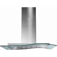
P31SS - Range hood BAUMATIC - Free user manual and instructions
Find the device manual for free P31SS BAUMATIC in PDF.


| Product Type | Cooker Hood |
| Brand | Baumatic |
| Model | P31SS |
| Color | Stainless Steel |
| Width | 60 cm |
| Mounting Type | Wall-mounted Chimney |
| Maximum Extraction Rate | 600 m³/h |
| Number of Speeds | 3 |
| Noise Level (max speed) | 65 dB |
| Lighting | 2 x 40W Halogen |
| Grease Filter Type | Aluminum Mesh |
| Charcoal Filter Included | Yes (for recirculation mode) |
| Ducting Diameter | 150 mm |
| Control Type | Push Buttons |
| Energy Class | C |
| Power Consumption (max) | 200 W |
| Voltage / Frequency | 220-240 V / 50 Hz |
| Product Dimensions (W x D x H) | 600 x 500 x 400 mm |
| Weight | 15 kg |
| Installation Requirements | Professional installation recommended |
| Maintenance | Clean grease filters monthly |
Frequently Asked Questions - P31SS BAUMATIC
User questions about P31SS BAUMATIC
0 question about this device. Answer the ones you know or ask your own.
Ask a new question about this device
Download the instructions for your Range hood in PDF format for free! Find your manual P31SS - BAUMATIC and take your electronic device back in hand. On this page are published all the documents necessary for the use of your device. P31SS by BAUMATIC.
USER MANUAL P31SS BAUMATIC
natural_image
Simple line drawing of a fish with fins and tail, no text or symbols presentUser Manual for your Baumatic
P30SS Pythagora 90 cm cooker hood
P31SS Pythagora 90 cm glass cooker hood

natural_image
Exterior view of a modern kitchen air conditioner unit with a single chimney against a black background (no text or symbols visible)
natural_image
Exterior view of a modern stainless steel kitchen range hood (no signage or text visible)
You will be mine ...
NOTE: This User Instruction Manual contains important information, including safety & installation points, which will enable you to get the most out of your appliance. Please keep it in a safe place so that it is easily available for future reference; for you or any person not familiar with the operation of the appliance.
DD 20/06/07
Contents Page
E n v i r o n m e n t a l
IMPORTANT SAFETY INFORMATION 5 - 7
Specifications of your cooker hood 8
Using your Baumatic cooker hood 9
| T | h | e | c | o | n | t | r | o | l | p | a | |
| Controlling | your | cooker | hood | 10 | ||||||||
| T | h | e | t | i | m | e | r | b | u | t | t | |
| Grease | filter | maintenance | alarm | 10 | ||||||||
Cleaning your Baumatic cooker hood 11
| The | grease | filter | 11 |
M a i n t e n a n c e
| Removing and cleaning the grease filter | 12 | |||||||||
| C | h | a | n | g | i | n | g | a | l | i |
| Fitting | the | carbon | filter | 14 | ||||||
I n s t a l l a t i o n
| E | l | e | c | t | r | i | c | a | l | c | o | n |
Before beginning installation 17
| Extraction mode or recirculation mode? | 18 | |||||
| Installing | your | cooker | hood | 19 | - | |
| Connecting | to | external | ducting | 23 | ||
| Fitting | the | chimney | section | 24 | - | |
| Completing | the | installation | 26 | |||
T r o u b l e s h o o t i n
Baumatic Ltd. conditions of guarantee 27
C o n t a c t d e t a i l
ENVIRONMENTAL NOTE
Note: Before discarding an old appliance, switch off and disconnect it from the power supply. Cut off and render any plug useless. Cut the cable off directly behind the appliance to prevent misuse. This should be undertaken by a competent person.
CONFORMITY TO W.E.E.E. DIRECTIVE
This appliance is marked according to the European directive 2002/96/EC on Waste electrical and Electronic Equipment (WEEE). By ensuring this product is disposed of correctly, you will help prevent potential negative consequences for the environment and human health, which could otherwise be caused by inappropriate waste handling of this product.
The symbol

on the product, or on the documents accompanying the product, indicates that this appliance may not be treated as household waste. Instead it shall be handed over to the applicable collection point for the recycling of electrical and electronic equipment.
Disposal must be carried out in accordance with local environmental regulations for waste disposal.
For more detailed information about treatment, recovery and recycling of this product, please contact your local city office, your household waste disposal service or the shop where you purchased the product.

natural_image
Simple line drawing of a tower with diagonal lines and circular base (no text or symbols)- The packaging materials that Baumatic uses are environmentally friendly and can be recycled.
- Please discard all packaging material with due regard for the environment.

natural_image
Illustration of an owl reading a book (no text or symbols present)Your safety is of the utmost importance to Baumatic. Please make sure that you read this instruction booklet before attempting to install or use the appliance. If you are unsure of any of the information contained in this booklet, please contact the Baumatic Technical Department.

IMPORTANT: Any installation work must be carried out by a qualified electrician or competent person.
- The hood must be installed in accordance with the installation instructions and all measurements followed.
If the cooker hood is installed for use above a gas appliance then the provision for ventilation must be in accordance with the Gas Safety Codes of Practice BS.6172, BS.5440 & BS.6891 (Natural Gas) and BS.5482 (LP Gas) 1994, the Gas Safety (Installation & Use) Regulations, the Building Regulations issued by the Department of the Environment, the Building Standards (Scotland) (Consolidated) Regulations issued by the Scottish Development Department. - It is dangerous to alter the specifications or to modify this product in any way. Do not tamper with it or attempt to modify the appliance in any way.
When installing the hood, ensure that the following recommended distances are observed between the highest point on the hob top (including the burners) and the bottom of the cooker hood:

Electric cookers: 700 mm
Gas cookers: 700 mm
Coal/ oil cookers: 800 mm
IMPORTANT: DO NOT SET YOUR COOKER HOOD LESS THAN 700mm ABOVE YOUR COOKER.
- When installed between adjoining wall cabinets, the cabinets must not overhang the hob.
- The edges of the cooker hood are sharp – be mindful of this as you handle your appliance, especially during installation and cleaning. DO NOT CLEAN IN BEHIND THE GREASE FILTERS!
- If the room where the cooker hood is to be used contains a fuel burning appliance such as a central heating boiler then its flue must be of the sealed or balanced flue type.
- If other types of flue or appliances are fitted, ensure that there is an adequate supply of air in the room.
- When the hood is being used in extraction mode, then ensure that the ducting is fire retardant and that there are no bends sharper than 90 degrees as this will reduce the efficiency of the hood.
- Ensure that the ducting used in extraction mode has the same diameter as the outlet hole all the way through.
- Keep young children from using, playing with or tampering with the cooker hood. Older children and infirm persons should be supervised if they are using the cooker hood.
- Your cooker hood is for domestic use only.

- Please dispose of the packing material carefully – children are especially vulnerable to it.
- Dirty oil is an even greater fire risk.
natural_image
Illustration of a firefighter in uniform holding a hose (no text or symbols)○ Always put lids on pots and pans when cooking on a gas cooker.

natural_image
Illustration of a cooking pot with a lid and handle (no text or symbols)- The manufacturer refuses to accept any responsibility for damages arising to the cooker hood or your property from a failure to observe the fire safety advice contained in this instruction booklet.
Remember that when in extraction mode, your cooker hood is removing air from the room it is installed in. Ensure that proper ventilation measures are being observed. Note that it removes odours from the room, not steam.
○ Warning - Always ensure that the cooker hood has been disconnected from the power supply before carrying out any work on the hood, including cleaning and replacing light bulbs.

natural_image
Abstract line drawing of a stylized figure with geometric shapes and a circular element, no text or symbols present.- Do not connect the ducting system of this appliance to any existing ventilation system which is being used for any other purpose.
- Do not install the appliance above a cooker with a high level grill.
- Never leave frying pans unattended during use as overheated fats and oils might catch fire.

natural_image
Illustration of a person cooking with a pan (no text or symbols)- Never flambé cook under this cooker hood.
- The cooker hood should not be exposed to a direct heat source from the cooking device underneath it, i.e. naked flame from a gas burner or heat from electric hob zones without a pan on them.
Do not attempt to use the cooker hood if it is damaged in any way. Never attempt to use it without the grease filters fitted or if the filters are excessively greasy!
- The lights on this appliance should only be used during operation of the cooker hood. They should not be left on permanently and used as a lighting source.
THE MANUFACTURER DECLINES ALL RESPONSIBILITY IN THE EVENT OF FAILURE TO OBSERVE THE INSTRUCTIONS GIVEN HERE, FOR INSTALLATION, MAINTENANCE AND SUITABLE USE OF THE HOOD.

Specifications of your cooker hood
Congratulations on purchasing a Baumatic Cooker Hood!
PRODUCT DIMENSIONS
Height (with chimney): 590 mm - 1090 mm
W i d t h : 9 0 0
D e p t h : 4 9 0
CHIMNEY DIMENSIONS
260 mm × 263 mm
Your cooker hood is fitted with:
○ High extraction tangential motor
- Touch control operation
○ Mark resistant coating FASTEEL
- 4 Speeds
- 2 Stainless steel grease filters
- 2 halogen lights
Extraction capacity: 800 m³/hr
Optional Extra: 1 x SCS14 carbon filter for air recirculation mode
Using your Baumatic cooker hood
The control panel
○ Make sure that it has been installed by a suitably qualified person, as per the information contained in Baumatic's installation instructions.
- Find the control panel, which is located at the front of the cooker hood.
- There are several buttons on the control panel, which perform separate functions.

Controlling your cooker hood
- Use the ON/OFF button to switch the cooker hood on.
- Use the plus and minus buttons to regulate the speed that the motor is running at.
- The speed level that you have selected will appear on the LCD display.
- To switch the cooker hood off, press the ON/OFF button again.
The timer button
- If you press the timer button whilst the cooker hood is in operation, then it will countdown for 15 minutes.
- During the countdown the light around the timer button will flash.
- When the countdown has finished the cooker hood will switch off.
- If you press the timer button again during the countdown, the light around the timer button will go out and the cooker hood will return to normal operation.
Grease filter maintenance reminder
- After approximately 30 hours of operation, the timer button will glow red. This means that the grease filters need to be cleaned.
- You should follow the grease filter cleaning operation that is outlined on pages 11-12 of this instruction booklet.
- When the grease filters have been put back in position, turn on the hood and then hold down the timer button until the red light goes out.
- Turn the hood off and then back on again, to check that the alarm has been reset.
- IMPORTANT: The grease filter should be cleaned at the time intervals suggested on page 11. You should not wait until the maintenance alarm activates before cleaning the grease filter.

IMPORTANT: TO MAINTAIN THE CORRECT FUNCTIONING OF THE CONTROL PANEL, WE RECOMMEND THAT YOU REGULARLY CLEAN THIS AREA.
Cleaning your Baumatic cooker hood
IMPORTANT: BEFORE CLEANING, ALWAYS ENSURE THAT YOU HAVE SWITCHED YOUR COOKER HOOD OFF AT THE OMNI-POLAR SWITCH, SET AT THE WALL FROM THE CABLE.
Cleaning
- Clean the external parts of your cooker hood with mild liquid detergent and a new damp cloth.
- Never use abrasive powder, corrosive solvents or brushes.
- Never insert pointed objects into the motor's protective grid.
- Only clean the control panel and grease filter grill with mild liquid detergents and a new damp cloth.
- If you are using the appliance in recirculation mode, then be sure to replace the carbon filter at the recommended interval (see section on "Fitting the carbon filter"). A build up of grease could cause a fire hazard.
- Never attempt to clean the area above the grease filters.
The grease filters
- Your cooker hood includes grease filters which help to absorb grease particles, to protect your kitchen & furniture from greasy residues.
- These metallic filters may become flammable if they become saturated with this greasy residue.
To prevent a fire hazard, the filters should be cleaned regularly. Depending on use, this should be done every 10-15 days or at least once a month, using hot water and normal washing-up detergent. - DO NOT WASH THE GREASE FILTERS IN A DISHWASHER.
Maintenance
Removing and cleaning the grease filters

natural_image
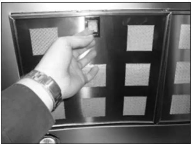
Hand inserting a small object into a black rectangular panel with patterned panels (no text or symbols visible)- Remove a grease filter by lifting up the catch and then pulling the filter away from the hood.

- Soak the grease filters in hot water and washing up liquid for about an hour.
- Rinse them off thoroughly with hot water.
- Repeat the process if required.
natural_image
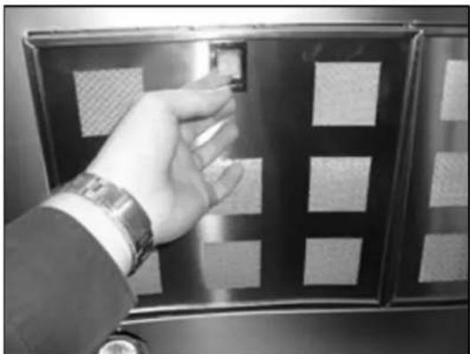
Hand inserting a small object into a dark metal panel with patterned panels (no text or symbols visible)- Refit the grease filters once they have dried.
○ IMPORTANT: Let the grease filters dry thoroughly before refitting them in the cooker hood.
Changing a light bulb

IMPORTANT: BEFORE ATTEMPTING TO CHANGE A LIGHT BULB, YOU MUST ENSURE THAT YOU HAVE DISCONNECTED THE COOKER HOOD FROM YOUR MAINS SUPPLY.
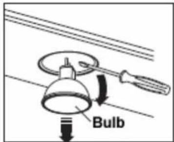
o Prior to touching the light bulbs ensure they are cooled down.
- Find the bulb that requires replacement, you will find it located in the light fixture which is on the underneath of the cooker hood.

○ Using a flat tipped screwdriver, remove the bulb and insert a new GU4 12V 20W (max) bulb.
○ IMPORTANT: Defective bulbs should be replaced immediately.
- If the light or lights still do not work, make sure that the lamps are fitted properly into their housings before you call for technical assistance.
Fitting the carbon filter
If the appliance is going to be used in recirculation mode then it is necessary to fit a carbon filter. This will help to absorb unpleasant odours caused by cooking.

IMPORTANT: BEFORE ATTEMPTING TO FIT OR REMOVE THE CARBON FILTER, YOU MUST ENSURE THAT YOU HAVE DISCONNECTED THE COOKER HOOD FROM YOUR MAINS SUPPLY.
natural_image
Hand inserting a small object into a metal panel with patterned panels (no text or symbols visible)- Remove the grease filters.
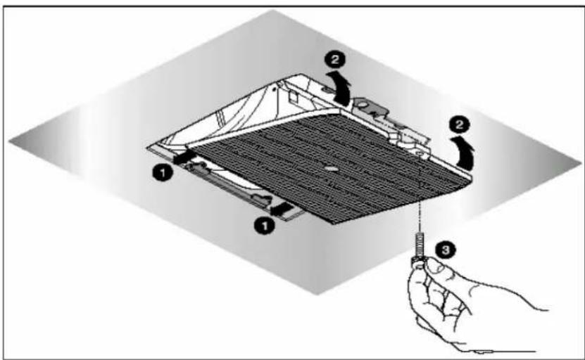
1) Locate the SCS14 carbon filter into the slots on the cooker hood, below the motor.
2) Push the other side of the filter upwards until it clicks into place.
3) Securely tighten the screw through the hole in the SCS14 carbon filter and the corresponding hole in the underneath of the cooker hood.
- Refit the grease filters.
- The carbon filter should be replaced every three months or if it shows signs of damage.
Installation
IMPORTANT: Before installation and usage read all the instructions and make sure that the voltage (V) and the frequency (Hz) indicated on the rating plate are exactly the same as the voltage and frequency in your home. The rating plate can be found behind the grease filters.
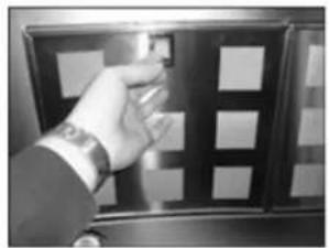
natural_image
Hand pressing a button on a blackboard with white squares (no visible text or symbols)

natural_image
Interior view of a mechanical or electrical enclosure with visible internal components and no readable text or symbolsThe manufacturer declines all responsibility in the event of the installer failing to observe all the accident prevention regulations in force, which are necessary for normal use and the regular operation of the electric system.
Electrical connection
YOUR COOKER HOOD IS INTENDED FOR FITTED AND PERMANENT INSTALLATION.

- The power cable must be connected to the terminals marked L (live) and N (neutral) in the hood and fixed with a cable clamp.
- The cooker hood's power cable must be fitted upstream from the electrical connection, using an omni-polar switch with a contact distance of at least 3 mm.
WARNING: THIS APPLIANCE MUST BE EARTHED. It should only be connected by a competent person, using fixed wiring via a double pole switched fused spur outlet. (UK ONLY).

We recommend that the appliance is connected by a qualified electrician, who is a member of the N.I.C.E.I.C. and who will comply with the I.E.E. and local regulations. The wires in the mains lead are coloured in accordance with the following UK code:
Blue = Neutral, Brown = Live, Green/Yellow = Ground
If you only find two wires in the main's lead (blue and brown), then neither must be connected to the earth terminal.
- As the colour of the wires in the appliance's mains lead may not correspond with the coloured markings identifying the terminals in your spur box, please proceed as follows:

- The blue wire must be connected to the terminal marked "N" (neutral), or coloured black.
- The brown wire must be connected to the terminal marked "L" (live), or coloured red.
Before beginning installation
- Check that the product purchased is of a suitable size for the chosen installation area. In addition check whether there is an electrical socket available that will be accessible once the hood is mounted. If the product is going to be used in extraction mode, then there should also be space to connect a ducting hose to the outside.
- Carry out all necessary masonry work prior to the fitting of the cooker hood.
- Ensure that all electrical connections are carried out by a suitably qualified person.
Before commencing installation of the cooker hood the grease filters should be removed. - Check the inside of the product and ensure that there is no transit packaging or any other materials, such as packets of screws, guarantees etc. These should be removed and kept for future use.
- If possible, disconnect and move freestanding or slot-in cookers from their position, to provide easier access to the rear wall and ceiling. If this is not possible, then a thick, protective covering should be placed over the worktop, hob top or cooker. This will help to protect these surfaces from damage and debris.
- Select a flat surface for assembling the cooker hood. Cover that surface with a protective covering and place all cooker hood parts and fittings on it.
- Rawl plugs are provided to secure the hood to most types of walls and ceilings. However a qualified technician must verify the suitability of the materials, in accordance with the type of wall and ceiling. The wall and ceiling must be strong enough to take the weight of the hood.
Do not tile, grout or silicone this appliance to the wall. This appliance is designed to be surface mounted only. - Remove any protective wrapping that has been put on the cooker hood or chimney sections, to protect them during transit.

IMPORTANT: YOU WILL HAVE TO DECIDE BEFORE INSTALLING YOUR COOKER HOOD WHETHER TO USE IT IN EXTRACTION MODE OR RECIRCULATION MODE.
What is the difference between extraction and recirculation modes?
In extraction mode, the stale air will be taken out of the room via external ducting.
In recirculation mode stale air is taken via the grease filter, and passed through a charcoal filter for purification. The air then re-enters the kitchen via an opening in the hood.
For optimum performance, we recommend that the cooker hood is used in extraction mode and connected to external ducting.
Unfortunately if you live in a flat or the hood is too far from an outside wall, this may not be possible. The only alternative is to recirculate the air.
Do I need a charcoal filter?
All cooker hoods have grease filters but if you are using your cooker hood in recirculation mode, then a charcoal filter must be fitted in addition to the grease filters.
Installing your cooker hood
- We recommend that at least two people install this hood.
IMPORTANT: YOUR COOKER HOOD SHOULD BE CONNECTED TO YOUR MAINS SUPPLY AFTER THE REST OF THE INSTALLATION PROCESS HAS BEEN COMPLETED.
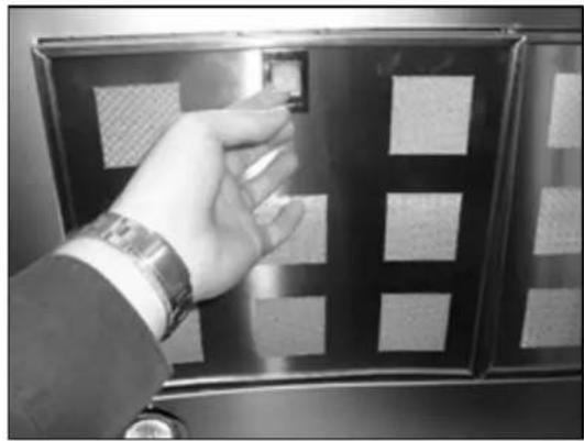
natural_image
Hand inserting a small object into a metal panel with patterned panels (no text or symbols visible)1) Remove the metal grease filters.
2) The mounting bar that you hang the hood on can be found on the side of the housing motor or in the package that contains the fixing screws and instruction manual.

3) Measure a distance of 700 mm from the hob top that will be underneath the cooker hood. Then measure out a further 310 mm above the height of measurement Y (Y being the thickness of the canopy section of the cooker hood).
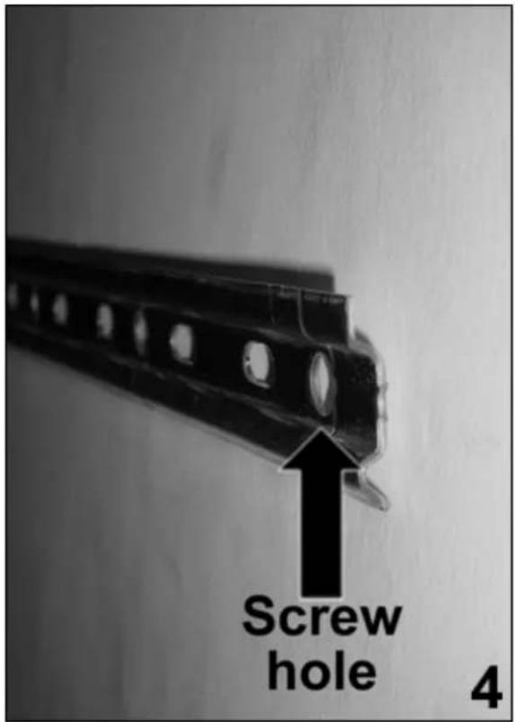
4) Using a pencil, mark the centre of the wall where the cooker hood will be installed. Place the mounting bar against the wall and ensure that the middle of it is placed on the centre mark.
- Use a pencil to mark the position of where the screw holes will be drilled.
○ Use a spirit level to ensure that the two markings are horizontally level.

5) Using a drill bit with an 8 mm diameter, make holes in the wall on the positions that you marked in step 4.
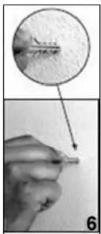
natural_image
Close-up of a hand holding a small object, with an inset showing a magnified view of a textured surface (no text or symbols visible)6) Insert rawl plugs into the two holes that you have just drilled.
- Screw the mounting bar to the wall using 2 x 8 mm screws.
○ IMPORTANT: You must make sure that the mounting bar is the right way up and the right way around. Please see picture 4 if you are unclear of the correct position for the mounting bar.
- Fully tighten these screws to fix the mounting bar to the wall.

natural_image
Technical illustration of a mechanical assembly with rotating components and directional arrows (no text or symbols)7) Hook the hood onto the mounting bar.

8) If required you can adjust the alignment of the cooker hood using the screws on the brackets that hook over the mounting bar.
- The top screw (B) adjusts the distance from the wall and the bottom screw (C) adjusts the height.
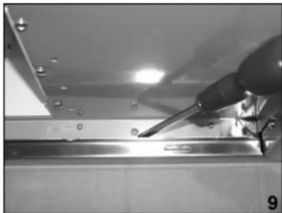
natural_image
Close-up of a metal tool applying liquid to a surface, with no visible text or symbols9) Mark the position of the lower screw holes that need to be drilled out in step 10. The holes can be found immediately below the motor housing. (The position of one of the holes is indicated in the above photograph by the screwdriver).

10) Remove the hood from the mounting bar and then using a drill bit with an 8 mm diameter, make holes in the wall on the positions that you marked in step 9.

natural_image
Close-up of a hand holding a small object, with an inset showing a magnified view of a wire or fiber (no text or symbols visible)11) Insert rawl plugs into the holes that you have just drilled.
- Follow steps 7 and 8 again (i.e. rehang the hood on the mounting bar and then adjust its angle and height, so that the drilled holes line up with the lower holes inside the hood again).
○ From the inside of the hood, tighten screws into the holes that you drilled in step 10.
○ IMPORTANT: You must fully tighten these screws, as they assist in fixing the hood to the wall.
Connecting to external ducting

12) Connect the coupling (D) to the top of the cooker hood.
- You may find an anti-draft flap included with the fixtures and fittings for the cooker hood. You should sit this in the top of the coupling.
- Connect a 125 mm ducting hose (E) to the coupling. Please note that the ducting hose is not supplied with the appliance.*
- The other end of the ducting hose should be connected to a discharge outlet that is suitable for cooking vapours. It should have a cross section of at least 150 cm ^2 .
- The maximum distance between the coupling and your discharge outlet should be 3 metres, with one 90 degree bend.
* It is possible to purchase a ducting kit from the Baumatic Spares Department (either the DK5 or DK10).
Fitting the chimney

13) Separate the two chimney sections (G and H).
Rest the bottom of chimney section G on the top of the hood. Making sure that the holes at the bottom of it, line up with the securing holes on top of the motor housing.
- If you want to install the appliance at its minimum height (i.e. only using one section of chimney), then you should complete steps 14-18 using chimney section G only.
14) Lift chimney section H upwards to the desired height. You must ensure that it is perpendicular to the hood.
○ Mark the side measurement of both sides of chimney section H on the wall with a pencil and then remove chimney sections G and H.

natural_image
Hand holding a white electronic device with buttons and display (no visible text or symbols)15) Take the fixing bracket (L) and place it between the two pencil marks that you made in step 14. Use a spirit level to ensure that the bracket is level before marking the position of the screw holes.
- Keeping the bracket in contact with the wall, use a pencil to mark the position of the holes at either end of the bracket on the wall.

16) Using a 4 mm drill bit, drill out holes on the pencil markings that you made in step 15. Insert rawl plugs into the holes and then use a screwdriver to secure the fixing bracket to the wall.

natural_image
Interior view of a mechanical device with a cylindrical component and wiring, no visible text or symbols17) Place chimney section G back onto the hood.
○ Make sure that the holes in the bottom of chimney section G line up with the securing holes on top of the main body of the motor housing.
From inside of the motor housing, screw chimney section G to the hood. You should make sure that you fully tighten these screws.
- Slide chimney section H back inside of chimney section G (unless you are installing the cooker hood at its minimum height and only using the lower chimney section).
○ IMPORTANT: Make sure that the vent on either side of chimney section H is pointing upwards and not inside of chimney section G.
18) Lift chimney section H up to the fixing bracket that you secured to the wall in step 16. Secure it to the fixing bracket using the screws provided. Make sure that these screws are fully tightened.
- If you are installing the appliance at its minimum height, then you should connect chimney section G to the fixing bracket.
Electrical connection
The electrical connection must correspond to the electrical requirement noted on the rating plate, which is placed inside of the cooker hood. The appliance should be connected to the electrical supply. See pages 16 – 17 for detailed information on the electrical connection.

Refit the grease filters and then switch on the mains supply to the appliance. Press the ON/OFF button and check that the appliance is operating correctly.
Troubleshooting
IMPORTANT: If your cooker hood appears not to be operating properly, before contacting the Baumatic Service Department, please refer to the checklist below.

My cooker hood will not start.
- Check that the hood is connected to the power supply and whether you have selected any of the fan speeds.

My cooker hood is not working effectively.
- Check that fan speed is set to an appropriate setting.
- Check that the grease filter is not dirty and if it requires cleaning.
- If the hood is set up for recirculation mode, check that the carbon filters do not need to be replaced.
- If the hood is set up for extraction mode, check that the ducting hose and discharge outlet are not blocked.

My cooker hood is noisy and/or vibrating.
- Check whether the installation has been completed as per the instruction booklet.
- It is normal to get a certain amount of noise and vibration, due to the extraction capacity of the cooker hood.
DO NOT MAKE ANY ATTEMPT TO REPAIR THE APPLIANCE YOURSELF. IF THE APPLIANCE IS STILL NOT OPERATING CORRECTLY, PLEASE CONTACT THE BAUMATIC SERVICE DEPARTMENT ON TELEPHONE NUMBER (0118) 933 6911.
Baumatic Ltd. Conditions of guarantee
Dear Customer,
Your new Baumatic appliance comes complete with a free 12 month guarantee covering both parts and labour costs resulting from defective materials or workmanship.
Baumatic also gives you the opportunity to automatically extend the guarantee period for a further 12 months at no extra cost, giving an initial guarantee period of 24 months. The extended guarantee period applies to England, Scotland, Wales and Northern Ireland only.
To qualify for your full 24 months guarantee you must register your appliance within 28 days of purchase to be covered under this guarantee. This can be done online via: www.baumatic.co.uk or through returning the guarantee card which can be found in each new Baumatic appliance.
* In addition, your appliance is covered by a 5 year parts warranty. Baumatic Ltd will provide free of charge the parts required to repair the appliance, only if they are fitted by a Baumatic engineer, for any defect that arises due to faulty materials or workmanship within a period of 5 years from the original purchase date.
* An additional 1 to 3 year insurance scheme for labour is available should you wish to extend the warranty period.
Should any person other than an authorised representative of Baumatic Ltd interfere with the appliance, the policy is negated and Baumatic Ltd will be under no further liability.
The guarantee covers the appliance for normal domestic use only, unless otherwise stated.
Any claims made under the terms of the guarantee must be supported by the original invoice/bill of sale issued at the time of purchase.
This guarantee is transferable only with the written consent of Baumatic Ltd.
If the appliance fails and is considered either not repairable or uneconomical to repair between 12 months (2 years if registered) and five years, a free of charge replacement will not be offered.
The guarantee for any replacement will only be for the remainder of the guarantee on the original product purchased.
The guarantee does not cover:
- Sinks and taps
- Failure to comply with the manufacturers instructions for use.
- The replacement of cosmetic components of accessories
- Accidental damage or wilful abuse.
- Subsequent loss or damage owing to the failure of the appliance or electrical supply
- Incorrect installation
- Losses caused by Acts of God, civil war, failure to obtain spare parts, strikes or lockouts
- Filters, fuses, light bulbs, external hoses, damage to bodywork, paintwork, plastic items, covers, baskets, trays, shelves, burner bases, burner caps, decals, corrosion, rubber seals.
In the course of the work carried out it may be necessary to remove the appliance from it operating position. Whilst all reasonable care will be taken, Baumatic Ltd cannot accept responsibility for damage sustained to any property whatsoever in this process.
This guarantee is in addition to and does not diminish your statutory or legal rights.
Contacting Baumatic Ltd
Sales
Service
Spares
Technical/Advice
TEL: 0118 933 6900
TEL: 0118 933 6911
TEL: 0118 933 6922
0118 933 6933
FAX: 0118 931 0035
FAX: 0118 986 9124
FAX: 0118 933 6942
0118 933 6942
For ROI (Republic of Ireland), please contact one of the numbers below:
TEL: 01-6266798
FAX: 01 - 6266634
Thanks you for buying Baumatic.
* Applies to UK, Scotland, Wales & Northern Ireland only (Republic of Ireland has 1 year labour & 1 year parts warranty only)
Baumatic®
You will be mine ...
Headquarters
Baumatic Ltd.
Baumatic Buildings,
6 Bennet Road,
Reading,
Berkshire
RG2 0QX, United Kingdom
Sales Telephone
+44 118 933 6900
Sales Fax
+44 118 931 0035
Service Telephone
+44 118 933 6911
Service Fax
+44 118 986 9124
Spares Telephone
+44 118 933 6922
Technical / Advice Telephone
+44 118 933 6933
E-mail:
sales@baumatic.co.uk
technical@baumatic.co.uk
Website
http://www.baumatic.com

www.baumatic.com

- User Manual for your Baumatic
- P30SS Pythagora 90 cm cooker hood
- P31SS Pythagora 90 cm glass cooker hood
- Contents Page
- ENVIRONMENTAL NOTE
- CONFORMITY TO W.E.E.E. DIRECTIVE
- The symbol
- IMPORTANT: Any installation work must be carried out by a qualified electrician or competent person.
- IMPORTANT: DO NOT SET YOUR COOKER HOOD LESS THAN 700mm ABOVE YOUR COOKER.
- Specifications of your cooker hood
- Congratulations on purchasing a Baumatic Cooker Hood!
- PRODUCT DIMENSIONS
- CHIMNEY DIMENSIONS
- Your cooker hood is fitted with:
- Using your Baumatic cooker hood
- The control panel
- Controlling your cooker hood
- The timer button
- Grease filter maintenance reminder
- Cleaning your Baumatic cooker hood
- Cleaning
- The grease filters
- Maintenance
- Removing and cleaning the grease filters
- Changing a light bulb
- IMPORTANT: BEFORE ATTEMPTING TO CHANGE A LIGHT BULB, YOU MUST ENSURE THAT YOU HAVE DISCONNECTED THE COOKER HOOD FROM YOUR MAINS SUPPLY.
- Fitting the carbon filter
- IMPORTANT: BEFORE ATTEMPTING TO FIT OR REMOVE THE CARBON FILTER, YOU MUST ENSURE THAT YOU HAVE DISCONNECTED THE COOKER HOOD FROM YOUR MAINS SUPPLY.
- Installation
- Electrical connection
- YOUR COOKER HOOD IS INTENDED FOR FITTED AND PERMANENT INSTALLATION.
- If you only find two wires in the main's lead (blue and brown), then neither must be connected to the earth terminal.
- Before beginning installation
- IMPORTANT: YOU WILL HAVE TO DECIDE BEFORE INSTALLING YOUR COOKER HOOD WHETHER TO USE IT IN EXTRACTION MODE OR RECIRCULATION MODE.
- What is the difference between extraction and recirculation modes?
- Do I need a charcoal filter?
- Installing your cooker hood
- IMPORTANT: YOUR COOKER HOOD SHOULD BE CONNECTED TO YOUR MAINS SUPPLY AFTER THE REST OF THE INSTALLATION PROCESS HAS BEEN COMPLETED.
- Connecting to external ducting
- Fitting the chimney
- Troubleshooting
- My cooker hood will not start.
- My cooker hood is not working effectively.
- My cooker hood is noisy and/or vibrating.
- Baumatic Ltd. Conditions of guarantee
- Contacting Baumatic Ltd
- Baumatic®
- Headquarters
- E-mail:
- Website
Brand : BAUMATIC
Model : P31SS
Category : Range hood