
TM-2430 - Sphygmomanometer A&D Médical - Free user manual and instructions
Find the device manual for free TM-2430 A&D Médical in PDF.


| Product Type | Ambulatory Blood Pressure Monitor |
| Model | TM-2430 |
| Brand | A&D Medical |
| Measurement Method | Oscillometric |
| Blood Pressure Range | Systolic: 60-260 mmHg, Diastolic: 40-200 mmHg |
| Pulse Rate Range | 30-200 bpm |
| Accuracy | Blood pressure: ±3 mmHg, Pulse rate: ±5% |
| Cuff Size | Adult (arm circumference 22-32 cm) |
| Memory | Up to 300 readings |
| Data Transfer | Via optional PC software and cable |
| Power Source | 2 AA batteries |
| Battery Life | Approximately 2 weeks of typical use (24-hour monitoring) |
| Dimensions | Approx. 70 x 100 x 30 mm |
| Weight | Approx. 150 g (including batteries) |
| Operating Temperature | 10°C to 40°C |
| Storage Temperature | -20°C to 60°C |
| Humidity | 15% to 95% RH |
| Protection Class | IP20 |
| Clinical Validation | Yes (British Hypertension Society, AAMI) |
| Accessories Included | Cuff, carrying case, batteries, user manual |
| Warranty | 2 years |
| Country of Origin | Japan |
Frequently Asked Questions - TM-2430 A&D Médical
User questions about TM-2430 A&D Médical
0 question about this device. Answer the ones you know or ask your own.
Ask a new question about this device
Download the instructions for your Sphygmomanometer in PDF format for free! Find your manual TM-2430 - A&D Médical and take your electronic device back in hand. On this page are published all the documents necessary for the use of your device. TM-2430 by A&D Médical.
USER MANUAL TM-2430 A&D Médical
Ambulatory Blood Pressure Monitor

This mark informs you about the operation of the product.
Note This manual and or the TM-2430 may be changed at any time to improve the product without notice.
Windows is the registered trademark of the Microsoft Corporation.
Macintosh is the registered trademark of Apple Computer, Inc.
EXCEL is the registered trademark of the Microsoft Corporation.

Contents
Before use
Compliance 2
Definitions 2
Precautions for Use 3
Notes on the Blood Pressure Recorder---- 4
Welcome
Welcome and Introduction 5
Product overview
Packing List and Component Names ---- 5
Display 7
Symbols----7
Specifications
Features 8
Functions and Specifications 8
Activating the Recorder
Replacing Batteries 12
Conditions When Recorder Switched On 13
Parameters for the Display and Clock 13
Selection for the Automatic Measurement 15
Deleting Old Data 19
Resetting the Recorder 19
Preparing the patient
Patient Instructions---- 20
Use of the Cuff Cover 21
Attaching the Cuff and Recorder 21
Preparation of the Carrying Case 23
Operation
Automatic Measurement (by Programed Time Intervals) ---- 24
Manual Measurement 24
To Stop a Current Measurement 24
Data transfer
Data Transmission to a Printer---- 25
Data Transmission to a Computer Using Analysis Software ---- 27
Options and accessories
Analysis Software and Communication Cables---- 28
Cuffs and Other Accessories 29
Maintenance
Checking Accuracy 30
Cleaning the Cuff and Recorder 31
Periodical inspection---- 31
Problem Solving 31
Error Codes 32
Compliance with European Directive 93/42 EEC for Medical Products
The device conforms to the following requirements: European Directive 93/42 EEC for Medical Products; Medical Products Act; European Standards for Electrical Medical Equipment EN 60601-1 (General Safety Provisions), EN 60601-2-30 (Particular Requirements for the Safety of Automatic Cycling Indirect Blood Pressure Monitoring Equipment), EN 60601-1-2 and EN 55011 (Electromagnetic Compatibility); European Standards pertaining to Non Invasive Blood Pressure Instruments EN 1060-1 (General Requirements), EN 1060-3 (Supplementary Requirements for Electromechanical Blood Pressure Measuring Systems). The above is evidenced by the CE mark of conformity accompanied by the reference number of a designated authority. This device is designed for adults only.
Compliance with FCC Rules
Please note that this equipment generates, uses and can radiate radio frequency energy. This equipment has been tested and has been found to comply with the limits of a Class A computing device pursuant to Subpart J of Part 15 of FCC rules. These rules are designed to provide reasonable protection against interference when this equipment is operated in a commercial environment. If this unit is operated in a residential area it might cause some interference and under these circumstances the user would be required to take, at his own expense, whatever measures are necessary to eliminate the interference. (FCC: Federal Communications Commission in the U.S.A.)
Compliance with the Australian EMC Frame work
The device conforms to the following requirements: EMC Emission standard for industrial, Scientific & Medical equipment AS/ NZS 2064-1997, EMC Generic Immunity standard AS/ NZS 4252. 1-1994. The above is evidenced by the C-Tick label.

Definitions
SYS Systolic Blood Pressure
DIA Diastolic Blood Pressure
DSD The Difference between Systolic Blood Pressure and Diastolic Blood Pressure.
Exhaust This means "releasing the cuff air as soon as possible".
Exhaust velocity This means the rate of depressurizing the cuff air.
Measurement cycle This means "a period between the start of cuff inflation and the end of exhausting the air".
Interval This is called a "block". A block consists of a start time and frequency.
bpm beats per minute.
Precautions
Batteries
☐ Use alkaline batteries (LR6 type, AA type, Mignon) or suitable Ni-Cd batteries.
☐ Do not mix new and used batteries in the recorder.
☐ If the recorder will not be used for a long period of time, remove the batteries from the recorder unless there is no risk of a SAFETY HAZARD arising.
A malfunctioning recorder
☐ If the recorder malfunctions, contact your vendor immediately.
Training
☐ Instruct the patient on how to stop the operation if there is an abnormal measurement, and how to remove the cuff if there is excessive arm pain.
☐ Provide patient with basic training on operation of ABPM system.
Repair
☐ Do not open the recorder case. Patient should avoid magnetic fields and high frequency equipment. Contact your vendor for further instructions.
Blood pressure measurement
☐ This device is intended for adult use only.
☐ The recorder may not make a measurement when a patient has continuous arrhythmia or the recorder senses noise due to the patients movement.
☐ Please check measurement values by other methods, if you suspect an erroneous value.
☐ Do not use this recorder on a person who is in critical condition or is in an intensive care unit.
☐ This device is intended for ambulatory patients.
Saving power
☐ Turn off the power switch when not in use.
☐ Please transfer the data as soon as possible. All measurement data, clock parameters, measurement parameters and internal system parameters are preserved by a backup battery when turning the power switch off. The backup battery life is few days.
Cuff
☐ Close the cuff fastener properly when attaching the cuff to a patient or replacing the cuff cloth. If the fastener is closed incorrectly, inflating cuff may damage the cuff.
Storage
☐ Do not store the recorder in the following places.
Excessive moisture
Excessive heat
Direct sun light
Excessive vibration
Exposure to dust
Exposure to corrosive chemicals
Magnetic fields
Before use
☐ Cover the RS-232C terminal using the rubber cap, to avoid dust.
☐ Confirm that the recorder works correctly.
☐ Confirm that the cuff and air hose are connected properly.
☐ Cuffs should be clean prior to use with patient.
☐ Clear the old data before starting a new measurement.
□ Avoid strong magnetic field and static electricity.
☐ Do not use this recorder near a high frequency surgical equipment.
During use
☐ The recorder should be operated by a medical professional who knows it well.
□ Stop using the recorder if the patient feels pain in the arm or if the recorder does not measure properly.
☐ If the recorder is exposed to excessive moisture, do not use. Immediately request service from vendor.
After use
□ Clean the recorder, cuff and accessories for the next use. Do not pull or kink hoses. Do not use organic solvent, antiseptic solution, etc.
☐ Turn off the power switch.
☐ Please use the original box for transportation of the monitor.
Periodic maintenance
☐ The recorder is a precision instrument. Please check all functions (every year) periodically. Contact your nearest A&D office for this inspection.
Environmental protection
☐ If you disuse the recorder, remove Ni-Cd battery and built-in Li battery from this recorder.
☐ Disuse Ni-Cd battery to its exclusive trash can because of recycling it.
☐ Dispose of Li ion battery in the recorder as dangerous object properly.
Thank you for your Purchase!
The A&D TM-2430 ambulatory blood pressure recorder enables you to accurately take a patient's blood pressure, automatically, at different preset times throughout a 24-hour period.
Recently, in the treatment of patients with hypertension, there has been an increasing need to prescribe medication according to the particular blood pressure fluctuation pattern of the patient. These patterns can be made more evident by using the TM-2430 recorder, and an analysis by a physician.
This manual will explain in simple language how this recorder works.
Patient
This blood pressure recorder is designed for an adult patient.
Environment
This blood pressure recorder is used in a hospital and / or patient's home.

Product overview

Packing List and Component Names
When you open this box, make sure you have everything as shown here :

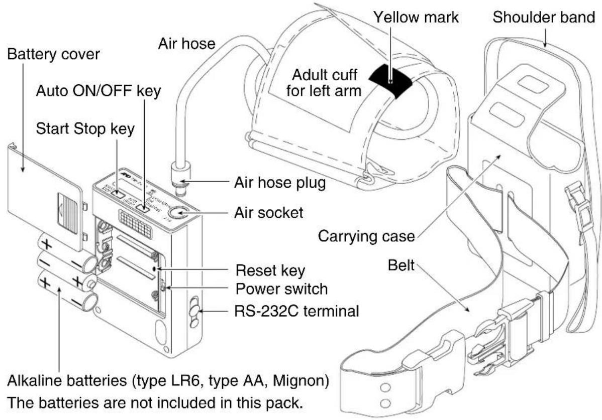
| Name Functions | |
| Power switch This is the main power switch. In the OFF state, all data and parameters are preserved by an backup battery. The backup battery life is approximately 10 days with the power off. | |
| AUTO ON/OFF key | ·When you press and hold the AUTO ON/OFF key, the automatic measurement is started or stopped alternately.·When you press the AUTO ON/OFF key at mode II of the automatic measurement, "S" is displayed or turned off alternately. This sign changes the interval for sleep. |
| START STOP key | ·When you press the START STOP key, a blood pressure measurement is started at once.·When you press and hold the START STOP key for approx. 3 seconds, the recorder proceeds to "Selection for the automatic measurement".·When you press and hold the START STOP key for approx. 6 seconds, the recorder proceeds to "Parameters for the display and clock".·When you press and hold the START STOP key for approx. 9 seconds, the recorder proceeds to "Deleting old data". |
| RS-232C terminal | This terminal is used for data output to a printer or computer. The optional RS-232C cable is necessary to output the data. |
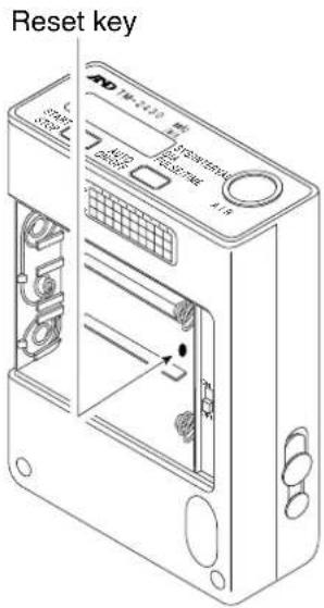
| Reset key All data and parameters are deleted. | |

Display

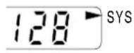
Systolic Blood Pressure display

Setup sign of automatic measurement

Diastolic Blood Pressure display

Setup sign of display and clock

Pulse display

Error display ex. "Set the clock"

Clock display
| Sign | Name Functions | |
| ▶ | Arrow | The arrow points to the kind of current display in the measurement result and function mode. |
| A | Automatic measurement | "A" is displayed when the automatic measurement is selected.When you press and hold the AUTO ON/OFF key, this sign is turned on or off alternately. |
| S | Sleep | When you press the AUTO ON/OFF key while in mode II of the automatic measurement, "S" is displayed or turned off alternately.With the "S" turned off, the time interval is 15 minutes.With the "S" turned on, the time interval is 30 minutes. |
| B | Low battery | When the recorder can not operate all functions due to low battery, this sign is displayed. The clock is still displayed. Please replace the batteries at once. |
| M | Full memory | When data memory is at full capacity, this sign is displayed. In this case, you can not perform another measurement. Transfer the data save in other media and delete. Then the "M" turns off. |

Symbols

Turning on the recorder.
Turning off the recorder.
Direction guide to install batteries.
Direct current.
SN Serial number.

Date of manufacture.

Attention symbol. "See instruction for use."

Recorder, Cuffs and tubings are designed to have special protection against electric shocks.

Specifications

Features
Portability
☐ The recorder weighs approx. 215g (including batteries) and is compact.
☐ The recorder is powered by LR6 type (AA) alkaline batteries. It is possible to replace the batteries with Ni-Cd rechargeable batteries.
Operation & management
☐ Clock and automatic measurement parameters may be set as needed.
☐ If you connect to a computer and use the optional software, clock and automatic measurement parameters can be easily set.
☐ There are three modes for automatic measurement. Mode 1 and Mode 2 are preprogrammed. Mode 3 is user programmable.
☐ The recorder can transmit data to a printer directly. (An adaptable printer is necessary to print the data. Refer to Section "Data Transmission to a Printer" for specifications of the TM-2480 printer.)
☐ The recorder has the built-in chargeable Li ion battery to keep the clock and automatic measurement parameters.
Analysis
☐ The time interval may be changed as needed.
☐ The patient's blood pressure can be measured immediately at any time.
☐ If you use the optional software, you can analyze the data extensively.
Smart measurement
☐ The measurement time is shortened by proper exhaust velocity control.
☐ The exhaust velocity adjustment is unnecessary, because the constant exhaust is properly controlled.
☐ In the automatic measurement cycle, these inflation values and stop values at exhaust are controlled to reduce the measurement time.

Functions and Specifications
Blood pressure measurement
☐ There are two ways of utilizing this device to record blood pressure measurements.
Automatic measurement - This automatic measurement works in accordance with internal clock, preset time intervals and preset mode. The measurement data is saved in memory.
Manual measurement ---- Any time you press the START STOP key, a blood pressure measurement is performed immediately. The measurement data is saved in the memory.
Automatic measurement
☐ This measurement starts or stops using the AUTO ON/OFF key. When this measurement is started, the recorder begins to work in accordance with preset time intervals from the preset time of the internal clock. Refer to "Selection for the automatic measurement".
☐ In the automatic measurement, an "A" appears in the upper left of the display.
☐ The recorder automatically measures the patient's blood pressure at the time that is pointed out by "the frequency" and "the start time" (by the programmed time intervals).
☐ When a measurement error occurs and there is 10 minutes until the next measurement, the measurement is retried after approx. 30 seconds.
☐ If a measurement is retried, only the data from the retry is saved.
☐ The recorder automatically adjusts the proper pressure, exhaust velocity and end of measurement.
☐ Refer to "Selection for the automatic measurement" and "Automatic measurement by programmed time intervals" about operation and entering parameters.
Stopping a measurement
☐ If you press the START STOP key during a measurement, the recorder exhausts the air and stops the measurement.
Concealing the measurement value
☐ This function works only while using automatic measurement.
☐ This function does not display the SYS, DIA or pulse rate for the automatic measurement, but the data is saved in memory.
☐ This function can select "reveal" or "conceal" at "Parameters for the display and clock". Refer to this section.
☐ If you select "conceal", the recorder displays the clock during a measurement.
☐ If you reset the recorder, this parameter is set to "reveal".
Pressurization
☐ The pressure is automatically selected by the recorder while in the automatic measurement mode.
☐ The first pressure is set to approx. 185 mmHg. This value automatically adjusts to the proper value after the first measurement. If the first inflation is not successful, the recorder retries twice.
☐ If you reset the recorder, the first inflation value is reset to 185 mmHg.
Memory
☐ The TM-2430 recorder can store 300 sets of data.
A data set consists of a SYS, a DIA and a pulse rate.
☐ When memory becomes full, the recorder displays an "M". Until you clear the data, you can not measure blood pressure.

When the recorder saves data for more than one patient, data management becomes complication. We recommend that patient data is transferred and cleared from memory.

When a "B" is displayed, the backup batteries that is preserving a patient's data are weak. Please replace batteries as soon as possible.
ID number
☐ If you reset the recorder, the ID number is set to "1".
☐ The ID number can be set using the optional software.
Performance specifications
| Measurement method Oscillometric | |
| Pressurization Display range | 0 ~ 320 mmHgInterval measurement 85 ~ 300 mmHg (Fitted)Manual measurement 185 mmHg (Fixed) |
| Measurement range Systolic Blood Pressure 60 ~ 280 mmHgDiastolic Blood Pressure 40 ~ 160 mmHgPulse rate 30 ~ 200 bpm | |
| Accuracy Pressure ±3 mmHgBlood pressure Conforming to 1992 AAMI standard(±3 mmHg or ±2% measurement whichever is greater)Pulse rate ±5 % | |
| Minimum display division | Pressure 1 mmHgPulse rate 1 bpm |
| Measurement | Automatic measurementManual measurement |
| Number of measurements | Apporx. 180 (Actual measurement number may vary due to environment and capacity of batteries) |
| Memory | Up to 300 sets of data |
| Display | Normal ClockDuring a measurement Pressure valueAfter a measurement SYS, DIA and pulse rateError code, function of concealing the measurement data |
| Clock | 24-hours (1997~2096 year, automatic leap year setting) |
| Batteries 3 x Alkaline battery (type LR6, type AA) or3 x Ni-Cd battery (type AA) | |
| Type of protection against electric shock | Internally powered equipment type BF |
| CE Marking | The label of the medical device by the EC directive. CE0366 |
| C-Tick Marking | The certification trade mark registered to the ACA by the Trademark office. N92 |
AAMI : Association for the Advancement of Medical Instrumentation
ACA: the Australian Communications Authority
CE marking and C-Tick marking are labeled only where they are required.
Communications/Data Connected to a computer, you can output the data and enterOutput parameters. Connected to a printer, you can print the data.Interface Specifications EIA RS-232C, Asynchronous, bi-directional, half duplexBaud rate 9600 bpsData bits 8 bitsStop bits 2 bitsX parameter Used (for computer)Not used (for printer)Parity NoneCode ASCIIRS-232C |
Environment specifications
| Operating environment | +10°C ~ +40°C (+50°F ~ +104°F), Less than 85%RH * |
| Transport and Storage | -20°C ~ +55°C (-4°F ~ +131°F), Less than 95%RH * |
* Non Condensing
Physical specifications
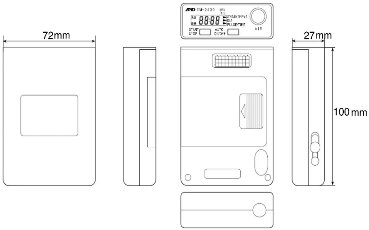
| Dimensions 72(W) x 100(D) x 27(H) mm2.8(W) x 3.9(D) x 1.0(H) in. | |
| Weight | Approx. 215 g (0.47lb) excluding cuff |

Activating the recorder

Replacing Batteries
Caution
☐ When "B" is displayed, the recorder can not take a measurement. Please replace the new batteries before using.
☐ If "B" is displayed during the measurement, replace with new batteries at once.
□ Use alkaline batteries or the specified rechargeable batteries for the recorder.
☐ Do not mix new and used batteries in the device.
Steps for replacing the batteries
Step 1
Open the battery cover.
Step 2
Turn off the power switch.
Step 3
Replace with new batteries. ( note the direction, "+" and "-".)
Step 4
Turn on the power switch.
Step 5
Close the battery cover.

flowchart
graph TD
    A["Battery cover"] --> B["Step 1"]
    B --> C["Step 5"]
    C --> D["New alkaline batteries"]
    D --> E["Step 3"]
    E --> F["Used batteries"]
    G["Power switch"] --> H["Step 4"]
    H --> I["Step 2"]
The recorder can be turned on in 3 different modes.
| When recorder is turned on. | Condition | Actions |
| The beeper sounds once and the clock is displayed. (Normal mode) | The recorder parameters are stored | You can use the recorder at once. |
| The beeper is sounded once and E00 blinks. | All parameters are lost. | Set up parameters of "display and clock" and "Automatic measurement". |
| The buzzer sounds four times and E00 blinks. | The mode after reset. All parameters are lost. |

Parameters for the Display and Clock
This setting selects the display during automatic measurement sequence and adjusts the clock parameters. The sequence number tells you which parameter you are adjusting.
Display & key

Items
| Sequence number | Value & range | Meaning of parameters | |
| 1 | 0 | Displaying clock only in automatic measurement | |
| 1 | Displaying pressure and result in automatic measurement | ||
| 5 | 00 ~ 99 | Years (1997 ~ 2096) | 5 97. |
| 6 | 1 ~ 12 | Month | 6 1. |
| 7 | 1 ~ 31 | Day | 7 1. |
| 8 | 0 ~ 23 | Hour | 8 0. |
| 9 | 0 ~ 59 | Minute | 9 00. |
Steps for setting the display and clock
This explanation uses the following examples.
ex. After reset, The measurement value is not displayed.
The clock is adjusted to 1997/05/27 14:28.
Step 1 Press and hold the START STOP key for approx. 6 seconds. The recorder displays for adjusting the display and clock.
Step 2 Press the AUTO ON/OFF key so as to display .10. (A selection where a clock is displayed only in automatic measurement)
Step 3 Press the START STOP key. The current year is displayed.
Step 4 Press the START STOP key. The current month is displayed.
Step 5 Press the AUTO ON/OFF key to display 5 (for May).
Step 6 Press the START STOP key. The current day is displayed.
Step 7 Press the AUTO ON/OFF key to display 27 (27th day).
Step 8 Press the START STOP key. The current hour is displayed.
Step 9 Press the AUTO ON/OFF key to display 14 (14th hour).
Step10 Press the START STOP key. The current minute is displayed.
Step11 Press the AUTO ON/OFF key to display 28 (28th minute).
Step12 Press the START STOP key to save these parameters. Then the recorder displays the clock.

flowchart
graph TD
    A["6:00"] --> B["START STOP 1 1"]
    B --> C["AUTO ON/OFF 1 0"]
    C --> D["START STOP 5 97"]
    D --> E["START STOP 6 1"]
    E --> F["AUTO ON/OFF 6 5"]
    F --> G["START STOP 7 1"]
    G --> H["AUTO ON/OFF 7 27"]
    H --> I["START STOP 8 0"]
    I --> J["AUTO ON/OFF 8 14"]
    J --> K["START STOP 9 0"]
    K --> L["AUTO ON/OFF 9 28"]
    L --> M["START STOP 14:28"]

Selection for the Automatic Measurement
This setting initializes measurement intervals that is based on the internal 24-hour clock.
Mode
mode I 07:00 \~ 21:59 The measurement is performed every quarter hour. 22:00 \~ 06:59 The measurement is performed every half hour.
mode II The AUTO ON/OFF key is pressed at rising and going to bed so that the measurement intervals are changed and the time during sleep can be distinguished on the data.
When the "S" is off, the measurement is performed every quarter hour. When the "S" is displayed, the measurement is performed every half hour.
mode III The measurement interval can change six times within a maximum of 24-hours. (The recorder can store six measurement intervals (blocks) in 24-hours. A block consists of a start time and frequency.)
Display & key

flowchart
graph TD
    A["Start"] --> B{Switch}
    B --> C["Stop"]
    C --> D["Selecting a mode"]
    D --> E["Auto ON/OFF"]
    E --> F["Saving a mode"]
    G["Sign of setting parameters for automatic measurement"] --> H["Mode"]
Steps for selecting a mode
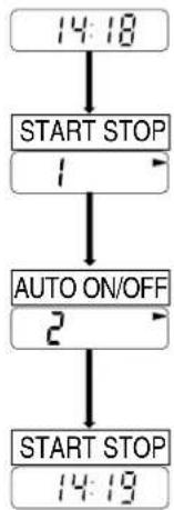
ex. Mode II is selected.
Step 1 Press and hold the START STOP key for about 3 seconds. The current mode is displayed.
Step 2 Press the AUTO ON/OFF key so as to display mode II.
Step 3 Press the START STOP key. The recorder stores the mode and displays the clock.
flowchart
graph TD
    A["14:18"] --> B["START STOP"]
    B --> C["1"]
    C --> D["AUTO ON/OFF"]
    D --> E["2"]
    E --> F["START STOP"]
    F --> G["14:19"]
Mode III Settings
Set up procedure
Before you enter into mode III, read the procedure below. Also, refer to the example on the next page for the setting procedure.
☐ Each blocks starting time must match the previous blocks finish time.
☐ The end of block 6 automatically equalizes to start time of the block 1.
☐ If you enter the block 1 start time in any other block, these parameters are saved and this sequence is finished.
☐ When selecting 120 minutes for the current frequency, you must adjust the start time of the next block so that the current block fits a multiple of 120 minutes. If you do not fit to the next start time, an error code is displayed.
☐ The recorder displays as 60 minutes and as 120 minutes.
☐ When you enter the sequence of mode Ⅲ settings, the recorder initializes each start time to the start time of block 1 and each frequency to "-" (not used). To read the current settings, press the START STOP key in this sequence.
Display & key

Items
| Sequence number | Parameters (monitor) | Meaning | Initial value |
| 01 | 0 ~ 23 o'clock | Start time of first block | 017 |
| 02 | -, 5, 10, 15, 20, 30, 60, 120 minutes | Frequency of first block | 0215 |
| 03 | 0 ~ 23 o'clock | Start time of second block | 0322 |
| 04 | -, 5, 10, 15, 20, 30, 60, 120 minutes | Frequency of second block | 0430 |
| 05 | 0 ~ 23 o'clock | Start time of third block | 057 |
| 06 | -, 5, 10, 15, 20, 30, 60, 120 minutes | Frequency of third block | 06- |
| 07 | 0 ~ 23 o'clock | Start time of fourth block | 07- |
| 08 | -, 5, 10, 15, 20, 30, 60, 120 minutes | Frequency of fourth block | 08- |
| 09 | 0 ~ 23 o'clock | Start time of fifth block | 09- |
| 10 | -, 5, 10, 15, 20, 30, 60, 120 minutes | Frequency of fifth block | 10- |
| 11 | 0 ~ 23 o'clock | Start time of sixth block | 11- |
| 12 | -, 5, 10, 15, 20, 30, 60, 120 minutes | Frequency of sixth block | 12- |
| 13 | 0 ~ 23 o'clock | End of sixth block | 13- |
The "-" means "not used".
Steps for automatic measurement
ex. First block 8:00 \~ 21:59 frequency is 30 minutes
Second block 22:00 \~ 5:59 frequency is 60 minutes
Third block 6:00 \~ 7:59 frequency is 10 minutes
Step 1 Press and hold the START STOP key for approx. 3 seconds. The current mode is displayed.
Step 2 Press the AUTO ON/OFF key so as to display for mode III.
Step 3 Press the START STOP key. The mode is stored and the current start time of the first block is displayed.
Step 4 Press the AUTO ON/OFF key so as to display "8" for 8:00 hours as the start time of the first block.
Step 5 Press the START STOP key. The current frequency for the first block is displayed.
Step 6 Press the AUTO ON/OFF key so as to display "30" for 30 minutes as the frequency for the first block.
Step 7 Press the START STOP key. The current start time of the second block is displayed.
Step 8 Press the AUTO ON/OFF key so as to display "22" for 22:00 hours as the start time for the second block.
Step 9 Press the START STOP key. The current frequency for the second block is displayed.
Step10 Press the AUTO ON/OFF key so as to display "for 60 minutes as the frequency of the second block.
Step11 Press the START STOP key. The current start time of the third block is displayed.
Step12 Press the AUTO ON/OFF key so as to display "6" for 6:00 hours as the start time of the third block.

flowchart
graph TD
    A["14:18"] --> B["START STOP"]
    B --> C["AUTO ON/OFF 3"]
    C --> D["START STOP 017"]
    D --> E["AUTO ON/OFF 018"]
    E --> F["START STOP 02-"]
    F --> G["AUTO ON/OFF 0230"]
    G --> H["START STOP 038"]
    H --> I["AUTO ON/OFF 0322"]
    I --> J["START STOP 04-"]
    J --> K["AUTO ON/OFF 0416"]
    K --> L["START STOP 058"]
    L --> M["AUTO ON/OFF 056"]
    M --> N["To next page"]

flowchart
graph TD
    A["Step13"] --> B["Press the START STOP key. The current frequency of the third block is displayed."]
    C["Step14"] --> D["Press the AUTO ON/OFF key so as to display "10" for 10 minutes as the frequency of the third block."]
    E["Step15"] --> F["Press the START STOP key. The current start time of the fourth block is displayed."]
    G["Step16"] --> H["Press the START STOP key. The recorder stores these parameters and displays the clock, (because the current start time of the fourth block is the same start time of the first block)."]

Deleting Old Data
Caution ☐ When the data is to be deleted, confirm that the data has already been transferred and saved. It is not possible to recover data that has been deleted.
☐ It is not possible to completely delete data, if the
START STOP
key is released while the beeper sounds at Step 2.
Steps for deleting old data
Step 1 Press and hold the START STOP key until is displayed. If you want to cancel this process, press the AUTO ON/OFF key.
Step 2 Press and hold the START STOP key once more until the beeper becomes silent.

Resetting the Recorder
If the recorder does not work correctly, press the reset key. The recorder deletes all data and parameters. The internal system is initialized.
Caution □ All data and parameters are deleted and preset initial parameters are reset.
☐ Do not press the reset switch too hard. Press this key gently so as not to damage the components inside.
□ Keep foreign matter away from the reset switch hole.
Steps for reset
Step 1 Open the battery cover.
Step 2 Turn off the power switch.
Step 3 Remove the batteries from the recorder.
Step 4 Press the reset key gently.
Step 5 Place new batteries in the recorder.
Step 6 Turn on the power switch. The recorder sounds the buzzer four times and E00 is displayed blinking.
Step 7 Set the parameters for the display and clock. Also, adjust the parameters for automatic measurement.
Patient instructions
Advise the patient on how to cope with mis-operation and contingencies.
Cautions during automatic measurement
☐ Patient should relax and be quiet, when the recorder starts inflating the cuff.
☐ Minimize noise and movement during the measurements.
☐ The recorder displays the patient's blood pressure within one minute after the measurement.
☐ There is the possibility of re-measuring the blood pressure after the last measurement. This occurs when the recorder did not acquire usable data and the frequency of the interval is above 10 minutes. The patient should relax and not move during the measurement.
□ Discontinue use of recorder if the patient feels pain in his arm.
Stopping or canceling an automatic measurement
☐ When the patient needs to stop a measurement, press the START STOP key. The recorder beeps, releases the air in the cuff and an error is displayed. The recorder will inflate the cuff for the next time period automatically.
☐ When the AUTO ON/OFF key is pressed and held for approx. 3 seconds, the recorder exits the automatic measurement mode and the "A" disappears. Conversely, by pressing the AUTO ON/OFF key again, the "A" will reappear.
Manual measurement
☐ For the patient to start a measurement at once, press the START STOP key.
☐ For the patient to stop this measurement, press the START STOP key.
Attention while attaching the cuff and recorder
☐ Do not drop or shake the recorder.
☐ The recorder and cuff are not water resistant. Prevent excessive moisture wetting the recorder and cuff.
☐ Do not place anything on the recorder.
☐ Prevent the air hose from disconnecting during sleep. Affix the air hose to the patient's body only as shown on page 24.
Replacing the batteries
☐ Replace with new batteries quickly, when "B" is displayed.

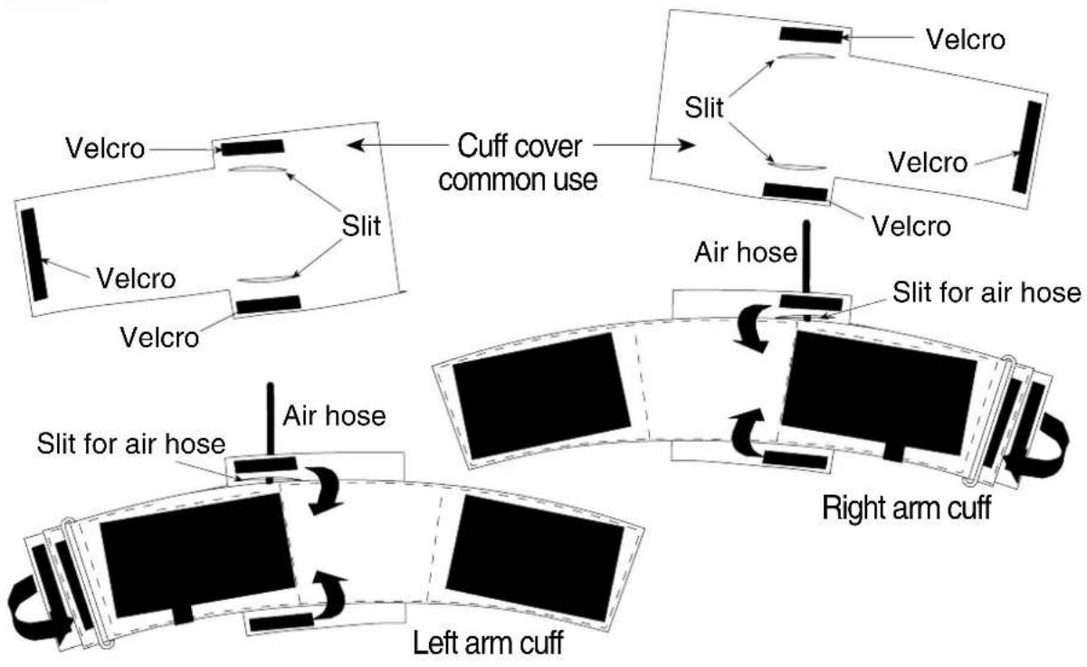
Use of the cuff cover
Step 1
Pass the air hose through the slit.
Step 2
Place the cover on the cuff as shown. Link them using the three velcro strips.
flowchart
graph TD
    A["Left arm cuff"] --> B["Slit for air hose"]
    B --> C["Air hose"]
    C --> D["Cuff cover common use"]
    D --> E["Slit"]
    E --> F["Velcro"]
    F --> G["Velcro"]
    G --> H["Velcro"]
    H --> I["Velcro"]
    I --> J["Velcro"]
    J --> K["Velcro"]
    K --> L["Velcro"]
    L --> M["Velcro"]
    M --> N["Velcro"]
    N --> O["Velcro"]
    O --> P["Velcro"]
    P --> Q["Velcro"]
    Q --> R["Velcro"]
    R --> S["Velcro"]
    S --> T["Velcro"]
    T --> U["Velcro"]
    U --> V["Velcro"]
    V --> W["Velcro"]
    W --> X["Velcro"]
    X --> Y["Velcro"]
    Y --> Z["Velcro"]

Attaching the cuff and recorder
Caution
☐ The standard cuff that is included with the TM-2430 is a left arm cuff.
☐ If the cuff is not attached at the correct position, the recorder may not measure the blood pressure correctly and an error may occur.
☐ The left cuff is for use on the left arm of about 20cm \~ 31cm. If you need a different cuff, purchase a cuff of the proper size and arm position. Refer to "Option and Accessories".
☐ Do not use, if the patient has dermatitis, etc.

Keep the cuff clean. Exchange the cuff cover for each patient. The cuff cover may be used for both right or left.
Steps for attaching the cuff and recorder
Step 1
Make a circle where the end of the cuff is passed through the ring.
Step 2
Search for the brachialis artery using palpation.
Step 3
Attach the cuff directly against the skin so that the yellow mark is directly over the brachialis artery and space it one inch above the inside of the elbow and the lower edge of the cuff.
Step 4
Wrap the cuff so that the ring is within the slide range, it is flat and does not slip down, but has room to insert two fingers. (If the ring is not within the slide range, you need a proper cuff.)
Step 5
Position the air hose over the shoulder and affix it on the patient using adhesive tape.
Step 6
Assemble the belt and carrying case.
Step 7
Position the belt so that the carrying case is on the right (left) side of the patient, when a patient attaches left (right) arm cuff.
Step 8
Connect the air hose plug to the air socket.
Step 9
Place the recorder into the carrying case.
Caution
☐ Do not disturb the cuff or air hose during the measurement because the recorder measures small pressure variations.


Attaching the Cuff and Recorder Initializing the Recorder

Preparation of the Carrying Case
□ Use the belt or shoulder band to attach the carrying case.
☐ We recommend the belt be used for added stability.
Using the Belt
Step 1 Insert the belt into the hole of the carrying case.
Step 2 Pull the belt from the hole of the carrying case.
Step 3 Pass the belt through the ring.
Step 4 Thread the belt through the front-hole and the rear-hole of the hook.
Step 5 Insert the belt to the ring again.

flowchart
graph TD
    A["Hook"] --> B["Step 4"]
    B --> C["Step 5"]
    C --> D["Step 3"]
    D --> E["Step 2"]
    E --> F["Step 1"]
    F --> G["Carrying case"]
    style A fill:#f9f,stroke:#333
    style B fill:#f9f,stroke:#333
    style C fill:#f9f,stroke:#333
    style D fill:#f9f,stroke:#333
    style E fill:#f9f,stroke:#333
    style F fill:#f9f,stroke:#333
    style G fill:#f9f,stroke:#333
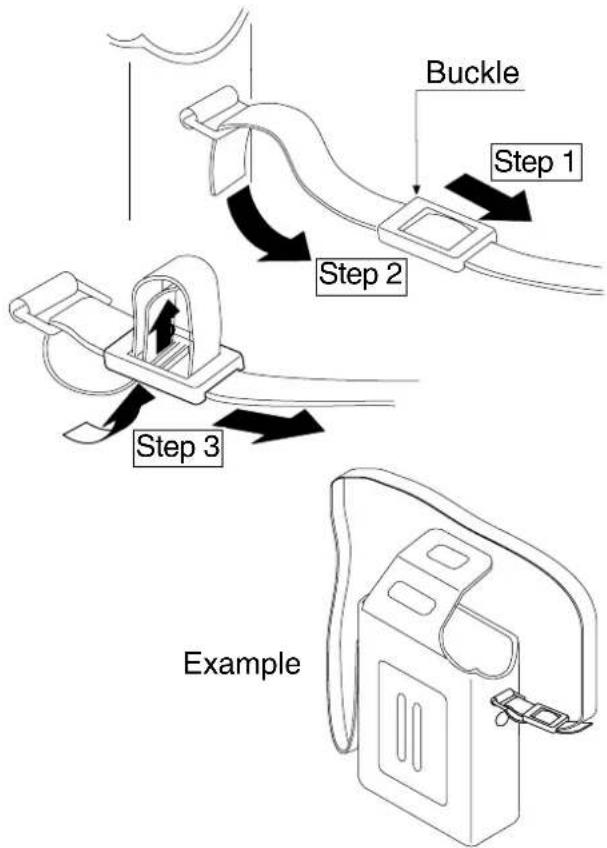
Using the Shoulder Band
Step 1 Insert the band into the buckle.
Step 2 Pass the belt through the ring.
Step 3 Thread the belt through the buckle. See illustration on right.

Operation

Automatic Measurement
Caution
☐ Automatic measurement uses the internal clock and parameters of automatic measurement. Refer to section "Parameters for the Display and Clock" and "Selection for the automatic measurement" for setting these parameters.
☐ Press and hold the AUTO ON/OFF key for approx. 3 seconds so as to turn off "A" symbol on display, when the patient stops the automatic measurement or detaches the cuff. If the automatic measurement mode is running without a patient arm or resistance, damage will occur to the cuff.
Starting or re-starting automatic measurement mode
Step 1 Confirm the parameters for automatic measurement. Refer to "Selection for the automatic measurement".
Step 2 Press and hold the AUTO ON/OFF key for about 3 seconds. When the "A" is displayed the recorder starts an automatic measurement based on the internal clock and the parameters for automatic measurement.
Operation using mode II (Sleep mode)
Step 1 Press the AUTO ON/OFF key turning off the "S" when the patient wakes up.
Step 2 Press the AUTO ON/OFF key turning on the "S" when the patient goes to bed.
Stopping or canceling automatic measurement
Step 1 When the AUTO ON/OFF key is pressed for about 3 seconds the recorder exits the automatic measurement mode and the "A" disappears. Conversely, by pressing the AUTO ON/OFF key again the "A" will reappear.

Manual Measurement
Step 1 Press the START STOP key. The recorder starts a measurement at once. The results are displayed and stored in memory.

To stop a Current Measurement
Step 1 Press the START STOP key during measurement. The recorder will stop the measurement at once and releases the air from the cuff.

Data Transfer
☐ The recorder transfers data to a printer or computer using the RS-232C terminal.
☐ We recommend analysis of the data using the optional "Doctor Pro" analysis software.
Caution
☐ Cap the RS-232C terminal to prevent dust and foreign matter from entering when this terminal is not in use.
□ Remove the recorder and cuff from the patient, when the recorder is connected to a printer or computer.

Data Transmission to a Printer
Caution
☐ The recorder intensely consumes the battery power while connected to the RS-232C cable. Disconnect the cable when not actually transferring data.
□ Maintain the power-on state while transmitting the data so that the data successfully transmitted.
☐ The RS-232C cable is required when connecting to a printer.
☐ The printer (to print the data) must have a serial interface and adapt to the RS-232C protocol of the recorder.
Specifications for an adaptable printer
| Transmission EIA RS-232C | |
Steps for data transmission
Step 1
Enter the parameters into the printer so that the data can be transmitted.
Step 2
Connect the cable to both the recorder and printer. Then the recorder displays . Refer to "Analysis Software and Communication Cable" about the cable.
Step 3
Set the printer to "ON LINE".
Step 4
Press the START STOP key. Then is displayed and the data is transmitted.
Step 5
When the transmission is finished, is displayed.
Step 6
Remove the cable at once. The clock is displayed.

flowchart
graph TD
    A["14:18"] --> B["Setup for printer"]
    B --> C["Connection"]
    C --> D["On line (Ready)"]
    D --> E["Start Stop"]
    E --> F["---"]
    F --> G["Remove the cable"]
    G --> H["14:25"]
Print sample
ABPM DATA TABLE
| No. | Date | Time | SYS(mmHg) | DIA(mmHg) | PUL(bpm) | ERR |
| 1 | `97/ 5/17 7:43 | 103 65 55 - | ||||
| 2 | `97/ 5/17 8:00 | 119 79 65 - | ||||
| 3 | `97/ 5/17 8:30 | 125 88 132 - | ||||
| 4 | `97/ 5/17 9:00 | 122 84 116 - | ||||
| 5 | `97/ 5/17 9:30 | 115 87 63 - | ||||
| 6 | `97/ 5/17 10:00 | 118 76 61 - | ||||
| 7 | `97/ 5/17 10:30 | - | - | - | 08 | |
| 8 | `97/ 5/17 10:35 | 116 82 68 - | ||||
| 9 | `97/ 5/17 11:00 | 114 75 62 - | ||||
| 10 | `97/ 5/17 11:30 | 122 81 94 - | ||||
| 11 | `97/ 5/17 12:00 | 123 86 88 - | ||||
| 12 | `97/=5/17 12:30 | 112 76 65 - |
Caution
☐ The recorder intensely consumes the battery power while connected to the RS-232C cable. Disconnect the cable when not actually transferring data.
□ Maintain the power-on state while transmitting the data so that the data is not damaged.
Steps for data transmission
Step 1
Connect the cable to both the recorder and printer. The recorder displays . Refer to "Analysis Software and Communication Cable" about the cable.
Step 2
Read the data using the optional analysis software. Refer to the software instruction manual.
Step 3
Remove the cable at once. The clock is displayed.

flowchart
graph TD
    A["14:18"] --> B["Connection"]
    B --> C["Reading data with software"]
    C --> D["Remove the cable"]
    D --> E["14:25"]

Options and accessories

Analysis Software and Communication Cables
The ABPM Data Analysis Software is a powerful tool for analyzing ambulatory blood pressure data. The following features are incorporated in this program:
- Statistical Analysis Statistical data may be viewed in full, partial, sleep, and awake periods by switching between clearly labeled tabs.
• Graphical Data Systolic/diastolic blood pressure, mean arterial blood pressure, and pulse data are displayed graphically to quickly determine patterns or trends in the data. - Data Conversion Data Convert feature automatically stores blood pressure and pulse data in standard (CSV) file format for use with popular spreadsheet programs.
- Printed Reports Custom data reports formats are easily defined and printed. "mini-report" feature automatically prints a compact summary report.
- On-line Help Built-in Help feature provides context-sensitive help at any time.
- Maximum Time Doctor Pro uses up to one week's data starting from Period the oldest reading.
Delete the old data in the recorder.
• Maximum number A maximum of 896 readings can be downloaded of readings using Doctor Pro. Doctor Pro software (TM-2430-13) includes diskette and communication cable (AX-K01502).
Cuffs (for serial no. M0600001 to M0600500)
| Name Order code | |
| Large cuff for left arm, 28 ~ 36 cm (11 ~ 14 inches) TM2430-02 | |
| Adult cuff for left arm, 20 ~ 31 cm ( 8 ~ 12 inches) | TM2430-06 |
| Small cuff for left arm, 15 ~ 22 cm ( 6 ~ 8 inches) | TM2430-07 |
| Adult cuff for right arm, 20 ~ 31 cm ( 8 ~ 12 inches) | TM2430-09 |
Cuffs (for serial no. M0600501 or over)
| Name Order code | |
| Large cuff for left arm, 28 ~ 36 cm (11 ~ 14 inches) TM2430-02A | |
| Adult cuff for left arm, 20 ~ 31 cm ( 8 ~ 12 inches) | TM2430-06A |
| Small cuff for left arm, 15 ~ 22 cm ( 6 ~ 8 inches) | TM2430-07A |
| Adult cuff for right arm, 20 ~ 31 cm ( 8 ~ 12 inches) | TM2430-09A |
Cuff sleeves
| Name Order code | |
| Large cuff sleeve for left arm 2 sleeves AX-133003299- | |
| Adult cuff sleeve for left arm 2 sleeves AX-133003137-S | |
| Small cuff sleeve for left arm 2 sleeves AX-133003298- | |
| Large cuff sleeve for right arm 2 sleeves AX-133003460-S | |
| Adult cuff sleeve for right arm 2 sleeves AX-133003300-S | |
| Small cuff sleeve for right arm 2 sleeves AX-133003461-S | |
Cuff cover
| Name Order code | ||
| Large cuff cover | 10 sheets | AX-133002066-S |
| Adult cuff cover | 10 sheets | AX-133002018-S |
| Small cuff cover | 10 sheets | AX-13A37410-S |
Others
| Name Order code | |
| TM-2430 Accuracy Diagnostic Kit | TM2430-90 |
| Recording sheet 10 sheets | AX-PP155-S |
| Carrying case | AX-003001955 |
Required equipment
☐Accurate office mercury sphygmomanometer or aneroid gauge with inflation system.
☐TM-2430 Accuracy Diagnostic Kit (TM2430-90).
☐A rigid cylinder sized to fit the cuff pressured.
Steps for checking accuracy
Step 1 Turn off the TM-2430 and remove the air hose from the unit.
Step 2 Construct the check system as this drawing.
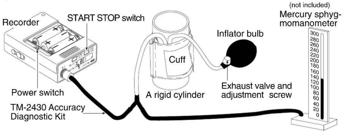
Step 4 Turn on the power switch, when you press and hold the START STOP key. The TM-2430 blinks the "0" of measurement value.
Step 5 Squeeze the inflator bulb until cuff pressure reaches to 50 mmHg. Verify that the difference between the blinking display of TM-2430 and mercury sphygmomanometer is within ±3 mmHg.
Step 6 Squeeze the inflator bulb until cuff pressure reaches to 150 mmHg. Verify that this difference is within ±3 mmHg.
Step 7 Squeeze the inflator bulb until cuff pressure reaches to 250 mmHg. Verify that this difference is within ±3 mmHg.
Step 8 Release the cuff air, turn off the TM-2430 and remove the kit. This blood pressure recorder is a precision instrument. Contact your nearest A&D office for this inspection, if you need repair.

Cleaning the cuff and recorder
☐Before cleaning the recorder, remove the battery cover and turn the power switch off. Remove the batteries.
☐The recorder is not water resistant, do not allow liquids to splash on or get into the case while cleaning.
☐After each use, wipe the case of the recorder with a clean lint free cloth, moistened with water and a mild detergent.
☐ Do not use antiseptic solutions, Alcohol, etc., to clean the recorder, hose or cuff.
☐Clean the cuff cloth and cuff cover by washing in water with a mild detergent. Do not scrub or wring them by hand. If the cuff cloth and cuff cover become contaminated, replace them with new covers.

Periodical inspection
☐This blood pressure recorder is a precision instrument. Please inspect the functions (every year) periodically. Contact your nearest A&D office for this inspection.

Problem solving
Caution
☐Do not open the case of the recorder because it uses delicate electrical components and an intricate air unit that could be damaged.
□If you can not locate and fix the problem, request service from your supplier, or from the A&D service group.
☐A&D service group will support authorized suppliers with technical information, spare parts and units.
| Problem | Cause | Treatment |
| No display at turning on. | Battery power has been consumed. | Replace with new batteries |
| Data lost while replacing batteries. | Unable to charge the internal sub battery. | Set monitor for clock display mode for approx. 24 hours. Do not take BP measurement. The sub-battery battery charges during clock display mode. |
| No pressure. | Air leakage at the connector, hose or cuff. | Confirm the cuff and air hose are not damaged and are connected correctly. |
Caution The error code updates without announcement.
| Error code | Meaning | Status Operation | and Treatment |
| E00 | No clock parameter | All parameters are lost. Reset status. | Enter clock parameters. Refer to "Setup of display and clock" |
| E03 | Pressure zero error | An error code is displayed without cuff inflation. | Release the air from the cuff completely. |
| E04 | Low battery | Measurement is stopped. An error code is displayed. Auto mode is quit. | Replace with new batteries. Restart the auto mode if you use it. |
| E05 | Inflation error | Inflation pressure does not reach the target pressure. | Wrap the cuff and connect to main unit exactly. If you can not clear the error, there may be an air leak and repair is necessary |
| E06 | Above 320mmHg | An error code is displayed. | Do not move and try to relax during the measurement. If you can not clear the error, the product will requier repair. |
| E07 | Controlled stop using STOP key | Air is exhausted. An error code is displayed. | Do not press the STOP key if you do not need to use it. |
| E08 | Pulsation can not be measured | Measurable pulsation is searched to 20mmHg in constant exhaust. An error code is displayed. | Do not move and try to relax during the measurement. The error occurs when measurable pulsations are not received due to thick cloth or quick motion. |
| E10 | Pulsations can not be detected because the patient may have moved. | In the measurement, Quick exhaust is executed. An error code is displayed. | Do not move and try to relax during the measurement. |
| E20 | Pulse rate < 30 200 < Pulse rate | An error code is displayed. | Measure the blood pressure by other methods. |
| E21 | DIA < 40 160 < DIA | DIA : Diastolic Blood PressureSYS : Systolic Blood PressureDSD : The Difference between Systolic Blood Pressure and Diastolic Blood Pressure. | |
| E22 | SYS < 60 280 < SYS | ||
| E23 | DSD < 10 150 < DSD | ||
| Error code | Meaning Status | Operation and Treatment | |
| E30 | Measurement is greater than 120 seconds. | Air is exhausted from the cuff, and an error code is displayed. | Repair is necessary because of slow inflation or slow constant exhaust. |
| E31 | The constant exhaust is greater than 60 seconds. | Air is exhausted from the cuff, and an error code is displayed. | Repair is necessary because of slow constant exhaust. |
| E32 | Clock error. | An error code is displayed. | If you not clear this error, the product needs repair. |
| E50 | Pressure offset error to measure pulsation. | An error code is displayed at restarting the product. | Release the air from the cuff completely, reset the product. If you not clear this error, repair is necessary. |
| E52 | Memory error. | An error code is displayed at restarting the product. | The product needs repair. |
| E53 | Battery contact is defective. | The measurement is stopped, air is released from the cuff and an error code is displayed. | Replace batteries correctly. If you can not clear this error, the product needs repair. |
| E55E56E57 | Exhaust error. | An error code is displayed at measurement. | Relax and do not move during the measurement. If this error occurs many times, repair is necessary. |
| E60 | Interval setting error. | Start time is not proper, interval of last block is not set in the unit of 120 min. | Enter parameters for the interval correctly. |
| E70E71E72E73 | RS-232C error. | The error code is displayed during communications. | Re-connect the communication cable. If you can not clear this error, the product needs repair. |
| E74 | Low battery for communication. | Replace batteries with new ones and restart communication. | |
| E75 | Protocol error due to external equipment. | Re-connect the communication cable. If you can not clear this error, the product needs repair. | |
| E90 | Pressure zero error for safety circuit. | This error code is displayed before the measurement. | Release the air from the cuff completely. |
| E91 | Safety circuit detects over load pressure. | Patient moved during the measurement. | Relax and try to quiet during the measurement. If it occurs in quiet, the recorder needs repair. |
| Other | Monitor code is displayed. | Reset. Turn on power switch again. | |
MEMO

- Contents
- Before use
- Welcome
- Product overview
- Specifications
- Activating the Recorder
- Preparing the patient
- Operation
- Data transfer
- Options and accessories
- Maintenance
- Compliance with European Directive 93/42 EEC for Medical Products
- Compliance with FCC Rules
- Compliance with the Australian EMC Frame work
- Definitions
- Precautions
- Batteries
- A malfunctioning recorder
- Training
- Repair
- Blood pressure measurement
- Saving power
- Cuff
- Storage
- During use
- After use
- Periodic maintenance
- Environmental protection
- Thank you for your Purchase!
- Patient
- Environment
- Packing List and Component Names
- Display
- Symbols
- Features
- Portability
- Operation & management
- Analysis
- Smart measurement
- Functions and Specifications
- Automatic measurement
- Stopping a measurement
- Concealing the measurement value
- Pressurization
- Memory
- ID number
- Replacing Batteries
- Caution
- Steps for replacing the batteries
- Parameters for the Display and Clock
- Display & key
- Steps for setting the display and clock
- Selection for the Automatic Measurement
- Mode
- Steps for selecting a mode
- Mode III Settings
- Set up procedure
- Steps for automatic measurement
- Deleting Old Data
- Steps for deleting old data
- Resetting the Recorder
- Steps for reset
- Patient instructions
- Cautions during automatic measurement
- Stopping or canceling an automatic measurement
- Manual measurement
- Attention while attaching the cuff and recorder
- Replacing the batteries
- Use of the cuff cover
- Step 1
- Step 2
- Attaching the cuff and recorder
- Steps for attaching the cuff and recorder
- Step 3
- Step 4
- Step 5
- Step 6
- Step 7
- Step 8
- Step 9
- Preparation of the Carrying Case
- Using the Belt
- Using the Shoulder Band
- Starting or re-starting automatic measurement mode
- Operation using mode II (Sleep mode)
- Stopping or canceling automatic measurement
- To stop a Current Measurement
- Data Transmission to a Printer
- Steps for data transmission
- Print sample
- Analysis Software and Communication Cables
- Required equipment
- Steps for checking accuracy
- Cleaning the cuff and recorder
- Periodical inspection
- Problem solving
- Caution The error code updates without announcement.
- MEMO
Brand : A&D Médical
Model : TM-2430
Category : Sphygmomanometer