
Ghost - Toys LEGO - Free user manual and instructions
Find the device manual for free Ghost LEGO in PDF.


| Brand | LEGO |
| Model | Ghost |
| Product Type | Building Toy Set |
| Recommended Age | 8+ years |
| Number of Pieces | Approximately 750 pieces |
| Box Dimensions (LxWxH) | 38 x 26 x 7 cm |
| Weight | 0.8 kg |
| Material | ABS Plastic |
| Battery Required | None |
| Assembly Required | Yes |
| Minifigures Included | 3 |
| Special Features | Building Instructions Included |
| Main Functions | Build and display model; interactive play |
| Care and Cleaning | Wipe with a dry cloth; avoid water |
| Safety Warnings | Choking hazard: small parts not for children under 3 |
| Spare Parts Availability | Available through LEGO Customer Service |
| Repairability | Modular design; bricks can be replaced individually |
| Country of Origin | Denmark |
| Item Number | Not specified in manual |
| Language of Manual | English |
Frequently Asked Questions - Ghost LEGO
User questions about Ghost LEGO
0 question about this device. Answer the ones you know or ask your own.
Ask a new question about this device
Download the instructions for your Toys in PDF format for free! Find your manual Ghost - LEGO and take your electronic device back in hand. On this page are published all the documents necessary for the use of your device. Ghost by LEGO.
USER MANUAL Ghost LEGO
Dear Sir/Madam, congratulations!
You have purchased a prestigious range hood of guaranteed quality. For best results, we suggest that you carefully follow the operating and maintenance instructions provided in this booklet; in addition, to order spare charcoal filters, use the special coupon on the cover.
natural_image
Technical line drawing of a mechanical device with no visible text or symbols


flowchart
graph TD
    A["V1"] --> B["AS"]
    B --> C["OK!"]
    style A fill:#f9f,stroke:#333
    style B fill:#ccf,stroke:#333
    style C fill:#cfc,stroke:#333
natural_image
Technical line drawing of a mechanical device with internal components and mounting brackets (no text or symbols)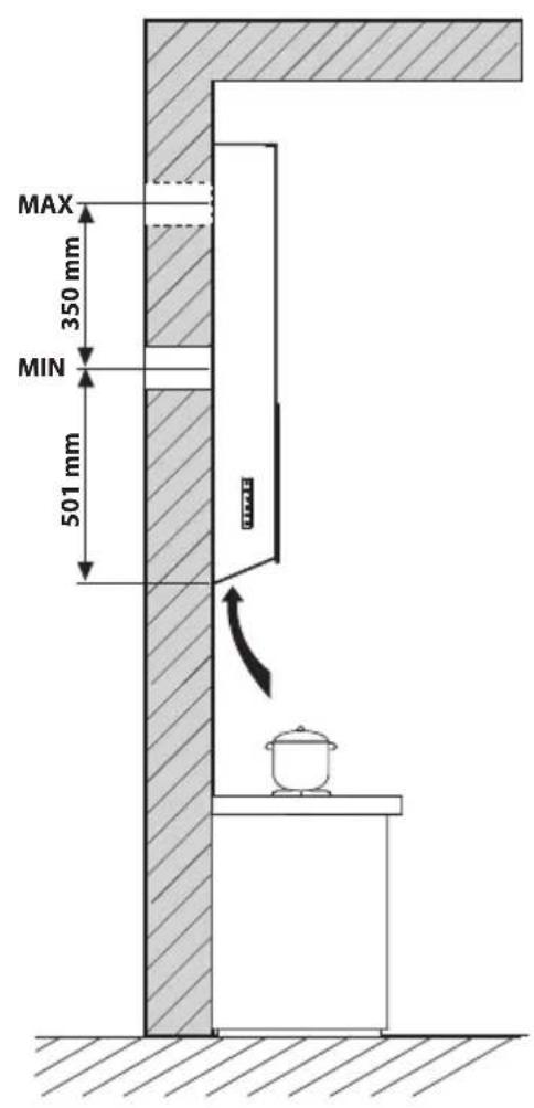


LIBRETTO ISTRUZIONI

AVVERTENZE

This instruction booklet must be kept together with the appliance for future reference. If the appliance is sold or consigned to other parties, check that the booklet is supplied with it, to ensure that the new user has the correct information on the operation of the range hood and is aware of the warnings. These warnings have been provided for the your safety and the safety of others. As a result, please read them carefully before installing and operating the appliance.
This appliance is not intended for use by young children or infirm persons unless they have been adequately supervised by a responsible person to ensure that they can use the appliance safely. Young children should be supervised to ensure they do not play with the appliance.
The appliance must be installed by qualified personnel, in accordance with the standards in force. If the supply cord is damaged, it must be re-placed by the manufacturer, its service agent or similarly qualified persons in order to avoid a hazard. Any modifications that may be required to the electrical system for the installation of the range hood must only be made by qualified electricians.
It is dangerous to modify or attempt to modify the characteristics of this system. In the event of malfunctions or if repairs are required to the appliance, do not attempt to solve the problems directly.
Repairs performed by unqualified persons may cause damage. For all repair and other work on the appliance, contact an authorised service/spare parts centre.
Always check that all the electrical parts (lights, exhaust device), are off when the appliance is not being used. Read the entire instruction booklet before performing any operations on the range hood.
The range hood must only be used for the exhaust of cooking fumes in home kitchens. The manufacturer disclaims all liability for any other use of the appliance.
The maximum weight of any object placed above the hood, or hung to it (if possible) must not exceed 1.5 kilos. After installing the stainless steel hood, clean it in order to remove any residue of the protective glue, and stains of grease or oil. The manufacturer recommends its cleaning cloth available for purchase. The manufacturer accepts no liability in case of damage caused by the use of different detergent types.

TECHNICAL SPECIFICATIONS
The technical data pertaining to the electric appliance The technical specifications of the appliance are shown on the rating plates located inside the range hood.

INSTALLATION
(Section reserved for qualified installers of the range hood)
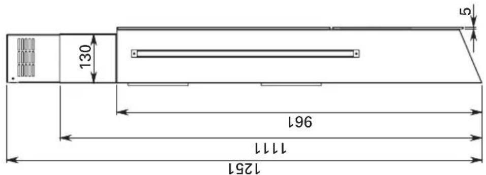
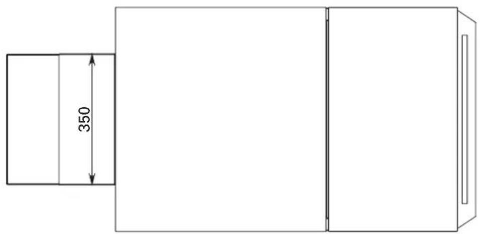
Follow the instructions described in fig. 1-2 when installing.
Should the instructions of the gas cooker specify a greater distance, take this into consideration.
In the outside exhaust version, the diameter of the fume discharge duct must be no smaller
than the range hood connection.
In the horizontal sections, the duct must slope slightly (around 10%) upwards, so at to better convey the air outside of the room.
Reduce curves to the bare minimum, and check that the length of the ducts is also the bare minimum.
Comply with the current regulations on air discharge into the atmosphere.
If other appliances that use gas or other fuels are being used at the same time (boiler, stove, fireplaces, etc.), make sure the room where the fumes are extracted is well ventilated, in compliance with the current regulations.
Assembly instructions: see section "0" of the booklet.

ELECTRICAL CONNECTIONS
(Section reserved for qualified installers)
WARNING!
Before doing any work inside the range hood, disconnect the appliance from the mains power supply.
Check that the wires inside the range hood are not disconnected or cut; if this is the case, contact your nearest service centre. The electrical connections must be performed by qualified personnel.
The connections must be performed in compliance with the legal standards in force. Check that the relief valve and the electrical system are able to support the load of the appliance (see the technical specifications in point B).
Some types of appliance are supplied with a cable without plug; in this case, "standardised" plugs must be used, keeping in mind that:
- the yellow-green wire must be used for the earth,
- the blue wire must be used for the neutral,
- the brown wire must be used for the phase; the cable must not come into contact with hot parts (over 70°C).
- fit a plug that is suitable for the load to the power cable, and connect it to a suitable power outlet.
For appliances that come supplied with cable and plug please ensure they are plugged into a circuit suitable for this appliance.
Please refer to a qualified person. (See technical specifications in point B).
The manufacturer declines all liability if the safety standards are not observed.

RANGE HOOD WITH OUTSIDE DISCHARGE (exhaust)
In this version, the fumes and steam from the kitchen are conveyed outside through an exhaust duct.
The exhaust conveyor that protrudes from the upper part of the range hood must be connected to a duct that carries the fumes and steam outside. In this version, the charcoal filters, if fitted, should be removed; to do this, see the instructions in point F. There must be adequate ventilation of the room when the range hood is used at the same time as appliances burning gas or other fuels, according to the standard.
Deviation for Germany:
When the range hood and appliances supplied with energy other than electricity are simultaneously in operation, the negative pressure in the room must not exceed 4 Pa (4x10 E-5 bar).

HOOD VERSION WITH INTERNAL RECIRCULATION (filtering)
In this model, the area passes through the carbon filters to be purified and is then introduced into the kitchen environment. To mount the filters, refer to section H2.

OPERATION


1: TIMER - FILTER RESET - SHUTTER OPENING - SHUTTER CLOSING
Timer: With the motor running, pressing this key will enable timed motor shut-down after 15 minutes. At the end of the 15 minutes the motor and the light will switch off and the mobile part will close back up. The red LED flashes to indicate that the function is enabled. Varying the speed of the motor will not interrupt the count. If the motor is stopped using key 4, the function will automatically switch off. When the timer function is enabled, it is possible to switch it off by pressing key 1.
Filter Reset: Every 30 hours of extractor fan operation, the filter signal will light up (steady red light). With the motor and light switched off, holding down key T1 will delete the signal and the shutter will open providing access to the filters. In this state it is not possible to start the motor and keys T2..T5 are disabled. Once the filters are put back in place, holding down key T1 will close the shutter and keys T2..T5 will start working again.
Opening the mobile part: When all of the leds are off (light and motor off) holding down this key allows you to open the mobile part of the hood so that maintenance can be carried out. During this state it is not possible to turn the motor on, keys T2..T5 are disabled. Key T1 is on.
Closing the mobile part: To exit the state where the mobile part is open and the is motor off, hold down key T1. The red T1 signal switches off and the T2..T5 keys will start working again at this time.
2: RECIRCULATION FUNCTION
Recirculation Function: When the motor is off, holding down key T2 will turn on the recirculation function, and the mobile part will open. Key T2 will flash. During the recirculation function (lasting 24 hours) the hood will stay on for 1 hour at the 1° (1st) speed, then it will stop for 3 hours and switch back on for another hour. These cycles are repeated until timeout.
When this function is enabled, other speeds may not be selected. To switch this function off, hold the T2 key down for at least 3 seconds. When the recirculation function is on the shutter stays open regardless of whether the motor is on / off.
3: DECREASE IN FAN SPEED
By pressing this key the motor will slow to the first speed.
4: FAN ON/OFF
Pressing this key turns the fan on/off at the same time as the shutter opens/closes. The
number of lights that light up on keys T3-T4-T5 indicates the fan speed level.
5: INCREASE IN FAN SPEED
By pressing this key the motor will pick up to the third speed.
6: - LIGHT - RADIO CONTROL ACQUISITION
Light: Briefly pressing key T6 will turn the light on and off. Key T6 will light up if the light is on. If the mobile part is closed, it will now open and the light will come on after a few seconds.
Radio control acquisition (optional): With the motor and light turned off, holding down key T6 will enable remote binding mode. Key T6 will flash for a maximum of 10 seconds. While it is flashing at least one radio control key must be pressed. The function will switch off when the 10 seconds are over, or earlier if a compatible remote control is detected.
MANAGING USE OF THE KEYS:
Radio control (optional): Place the device away from sources of electromagnetic waves which may interfere with the electronics of the hood. Maximum operating distance of 4 metres. This distance may vary based on any electromagnetic interference from other devices.
| Function of the remote control | DESCRIPTION |
| Light Key | Pressing the Light key will switch the light on/off |
| ‘-’Key | Pressing the ‘-’ Key will decrease motor speed. If 1° (1st) speed is in gear, pressing the ‘-’ key will turn off the motor |
| ‘+’Key | If the motor is turned off, pressing the ‘+’ key will activate the motor at 1° (1st) speed. If the motor is operating, pressing the ‘+’ key will increase motor speed up to the maximum. |
| Timer Key | If the motor is active, pressing the timer key will activate/deactivate the timer function |
| Code Change(only in case of malfunction) | Press the “Luce” (Light) key together with the “Timer” key of the remote control until the blue LED begins to slowly flash. If the “-” key of the remote control is pressed within 5 seconds, the new code will be generated and memorised. Memorisation is confirmed by 3 brief flashes of the LED.To return to the default code, apply pressure on the “-” key together with the “+” key for over 5 seconds. Memorisation of the default code will be signalled with 3 brief flashes of the LED.Each time that a new code is generated or that the default code is set in the remote control, it is necessary to also carry out the previously described Remote Binding (Light Key of the pushbutton) procedure. |

FILTERS REMOVING AND REPLACING'S INSTRUCTIONS
1. METAL FILTERS
To remove the metal filter, open the door, following the procedure indicated in section G (door opening button 1). This way, the filters can be removed by acting on the appropriate handle.
2. CARBON FILTERS
Remove the metal filters as indicated in section H1. This way the carbon filters can be accessed and be removed easily.
ONLY FOR ITALY: Download the filter order module from the website:
www.falmec.com (access the drop-down assistance menu).

LIGHTING ASSEMBLY AND REPLACEMENT
The range hood is equipped with high efficiency, low consumption LED strips with extremely long duration under normal use conditions. LED strip re placement must be carried out only by qualified technicians.

MAINTENANCE AND CLEANING
Constant maintenance ensures the correct operation and efficiency of the appliance over time. Special attention should be paid to the metal grease-trapping filters and the charcoal filters. Frequent cleaning of the filters and their supports will ensure that fats and grease do not accumulate on the range hood, with the consequent risk of fire.
1. METAL GREASE-TRAPPING FILTERS
These trap the fat and grease particles suspended in the air, and therefore should be washed every month in hot water and detergent, without bending them. Wait until they are completely dry before repositioning them. To remove and replace these filters, see the instructions in point H1. This operation should be performed at regular intervals.
2. CHARCOAL FILTERS
These trap the odours present in the stream of air that passes through them. The air is purified by passing a number of times through the filters and being recirculated into the kitchen. The charcoal filters cannot be cleaned, and should be replaced on average every 3-4 months (according to use). To replace the charcoal filters, see the instructions in point H2.
3. CLEANING THE OUTSIDE OF THE APPLIANCE
It is advised to clean the external hood surfaces at least every 15 days in order to avoid that oily or greasy substances affect the steel surfaces.
The outside of the range hhod should be cleaned using a damp cloth and neutral liquid detergent or denatured alcohol.
In case of fingerprint-less finish (fasteel) clean only with water and neutral soap using clean with a soft cloth, rinse and wipe dry thoroughly. Do not use products that contain abrasive substances, rough cloths or cloths specifically designed for cleaning steel. Using abrasive substances or rough cloths will inevitably damage the finish of steel. The steel surface will be irrevocably damaged if the instructions above are not complied with. Keep these instructions together with the instructions for use of your hood.
The manufacturer accepts no liability for any damage caused by non-compliance with the instructions above.
4. CLEANING THE INSIDE OF THE APPLIANCE
The electrical parts or parts of the motor assembly inside the range hood must not be cleaned using liquids or solvents.

Do not use abrasive products.
above operations must be performed after having disconnected the appliance from the mains power supply.

SAFETY WARNINGS


The electrical system features an earth connection in compliance with international safety standards; furthermore, it is compliant with the European standard for electromagnetic compatibility.
Do not connect the appliance to flues (from boilers, fireplaces, etc.). Make sure the mains voltage corresponds to the values on the rating plate located inside the range hood. The minimum safety distance between the cooktop and the range hood must be at least 65 cm.
Never cook on "open" flames under the range hood.
Check deep-fryers during use: superheated oil may be flammable.
- Ensure there is adequate ventilation of the room when the rangehood is used at the same time as appliances burning gas or other fuels.
- Do not flambe under the rangehood
- The exhaust air must not be discharged into a flue which is used for exhausting fumes from appliances burning gas or other fuels.
- Ensure that all regulations concerning the discharge of exhaust air have been fulfilled before you use the appliance.

Before performing any cleaning or maintenance operations, disconnect the appliance by unplugging it or using the main switch. The manufacturer disclaims all liability for any damage that may be directly or indirectly caused to people, things and animals due to the failure to follow all the instructions provided in this booklet and above all the warnings relating to the installation, operation and maintenance of the appliance.

WARRANTY
The new equipment is covered by warranty. The warranty conditions are provided by the distributor.

The manufacturer is not liable for any inaccuracies in this booklet resulting from printing or transcription errors. The manufacturer reserves the right to modify its products as it considers necessary or in the interests of the user, without compromising their essential safety and operating characteristics.

ASSEMBLY INSTRUCTIONS
Phase 1
(Fig. A)
1-2) Mark 4 drilling points on the wall, complying with the measures indicated in figure "A".
3) Drill using a 8mm tip, insert 4 expansion plugs and relative screws (V1) without tightening them fully.
(Fig. B)
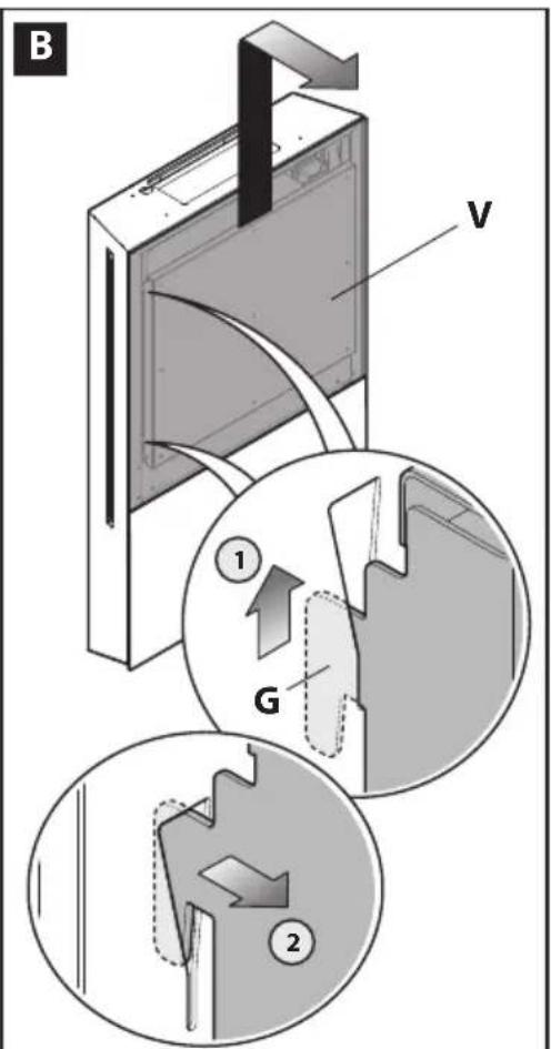
1-2) Remove glass "V" from the hood body: lift it until the hooks (G) (1) are released and then pull it outwards (2).
(Fig. C)
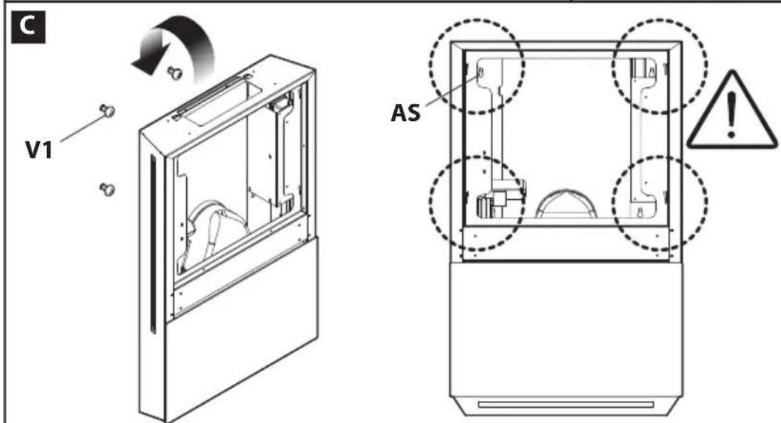
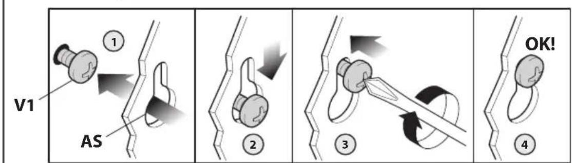
1) Insert the head of the screws (V1) inside the large part of the 4 shaped holes (AS) located at the rear side of the hood.
2) Lower the hood until placing the 4 screws (V1) inside the narrow part of the shaped holes (AS).
3) Fully tighten the screws (V1).
Phase 2
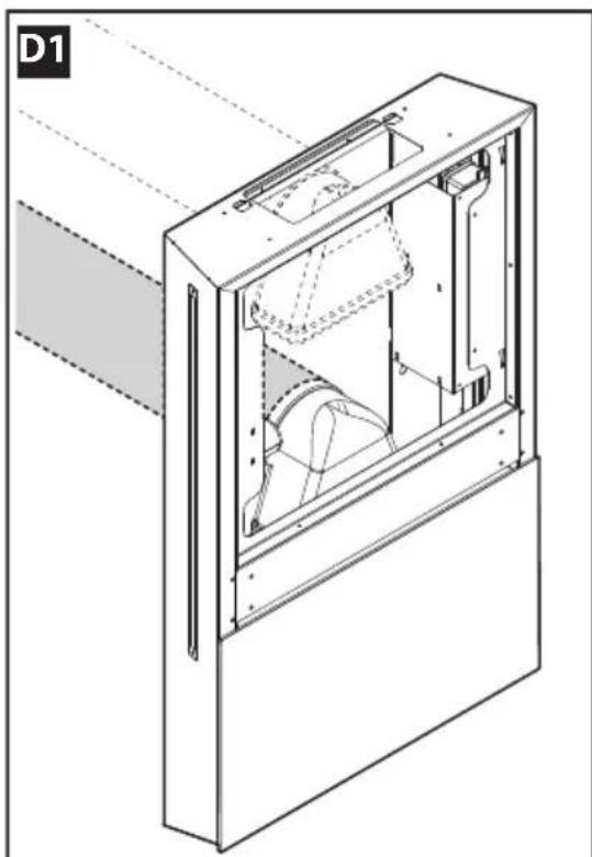
(Fig. D1) Hoods with wall fume outlet
1) Connect the hood to the fume exhaust pipe using the provided fitting.
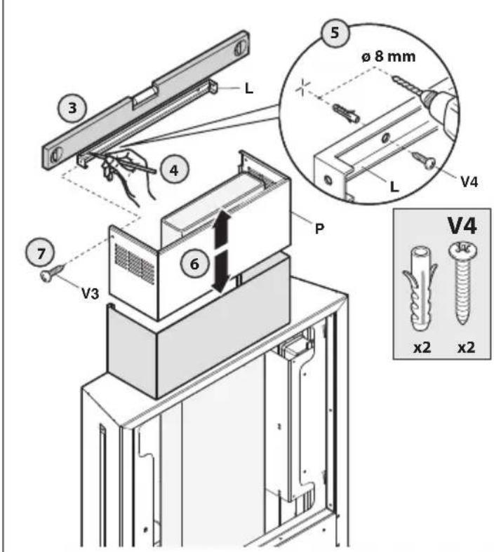
(Fig. D2) Hoods with ceiling fume outlet
1-2) Detect the optimal height H of the fume exhaust pipe. Fasten the flue (C) to the hood body using 4 "V2" screws.
3) Place the brackets (L) on the wall, ensuring it is perfectly levelled.
4) Mark the drilling points.
5) Drill using a 8mm tip, insert 2 expansion plugs and lock the bracket (L) to the wall with 2 screws (V4).
6) Place the extension (P) inside the flue (C) and make it scroll upwards or downwards until obtaining the required height.
7) Screw the extension (P) to the bracket (L) using the two screws (V3).
Phase 3
1) Perform the electric connection (only after having disconnected the power supply).
2) Remount glass "V", which has been previously removed.
3) Power the hood complying with the regulations in force (see sec. D of the booklet).

BEDIENUNGSANLEITUNG

HINWEISE

MANUAL DE INSTRUÇÕES

ADVERTÊNCIAS

4: ON/OFF WENTYLATORA
5: WZROST PRĘDKOŚCI WENTYLATORA
FILTRY INSTRUKCJE WYJMOWANIA I WYMIANY
1. FILTRY METALOWE



- LIBRETTO ISTRUZIONI
- AVVERTENZE
- TECHNICAL SPECIFICATIONS
- INSTALLATION
- ELECTRICAL CONNECTIONS
- WARNING!
- RANGE HOOD WITH OUTSIDE DISCHARGE (exhaust)
- HOOD VERSION WITH INTERNAL RECIRCULATION (filtering)
- OPERATION
- 1: TIMER - FILTER RESET - SHUTTER OPENING - SHUTTER CLOSING
- 2: RECIRCULATION FUNCTION
- 3: DECREASE IN FAN SPEED
- 4: FAN ON/OFF
- 5: INCREASE IN FAN SPEED
- 6: - LIGHT - RADIO CONTROL ACQUISITION
- MANAGING USE OF THE KEYS:
- FILTERS REMOVING AND REPLACING'S INSTRUCTIONS
- METAL FILTERS
- CARBON FILTERS
- LIGHTING ASSEMBLY AND REPLACEMENT
- MAINTENANCE AND CLEANING
- METAL GREASE-TRAPPING FILTERS
- CHARCOAL FILTERS
- CLEANING THE OUTSIDE OF THE APPLIANCE
- CLEANING THE INSIDE OF THE APPLIANCE
- SAFETY WARNINGS
- WARRANTY
- ASSEMBLY INSTRUCTIONS
- Phase 1
- (Fig. A)
- (Fig. B)
- (Fig. C)
- Phase 2
- (Fig. D1) Hoods with wall fume outlet
- (Fig. D2) Hoods with ceiling fume outlet
- Phase 3
- BEDIENUNGSANLEITUNG
- HINWEISE
- MANUAL DE INSTRUÇÕES
- ADVERTÊNCIAS
- 4: ON/OFF WENTYLATORA
- 5: WZROST PRĘDKOŚCI WENTYLATORA
- FILTRY INSTRUKCJE WYJMOWANIA I WYMIANY
- FILTRY METALOWE
Brand : LEGO
Model : Ghost
Category : Toys