
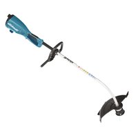
DUR365UZ - String Trimmer MAKITA - Free user manual and instructions
Find the device manual for free DUR365UZ MAKITA in PDF.


| Product type | Cordless grass trimmer |
| Brand | Makita |
| Model | DUR365UZ |
| Power source | Lithium-ion battery 36 V (2 × 18 V) |
| Battery type | Makita LXT, 18 V compatible |
| Cutting width | 35 cm |
| Line diameter | 2.0 mm |
| Line type | Nylon line, bump feed or automatic |
| No-load speed | 6000 rpm |
| Motor | Brushless |
| Key features | Dual power switch, motor protection |
| Functions | Grass trimming, light brush cutting |
| Weight (with battery) | 4.5 kg |
| Dimensions (L × W × H) | 180 × 28 × 28 cm |
| Shaft length | Adjustable, approx. 120 cm |
| Handle type | U-handle with adjustable grips |
| Sound level | 82 dB(A) (guaranteed) |
| Vibration level | 2.5 m/s² |
| Safety | Line guard, quick motor stop, double safety trigger |
| Maintenance | Regular cleaning, check screws, lubricate shaft |
| Spare parts | Available: cutting head, line, guard, batteries, charger |
| Repairability | Repairability index 8.2/10 (estimate) |
| Usage | Small to medium gardens |
Frequently Asked Questions - DUR365UZ MAKITA
User questions about DUR365UZ MAKITA
0 question about this device. Answer the ones you know or ask your own.
Ask a new question about this device
Download the instructions for your String Trimmer in PDF format for free! Find your manual DUR365UZ - MAKITA and take your electronic device back in hand. On this page are published all the documents necessary for the use of your device. DUR365UZ by MAKITA.
USER MANUAL DUR365UZ MAKITA
GB Cordless Grass Trimmer Instruction manual
natural_image
Line drawing of a handheld medical or laboratory instrument with articulated arms and connectors (no text or symbols)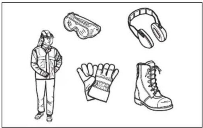
natural_image
Illustration of a worker in safety gear with five different hand tools (sleeve, helmet, glove, pair, and boot) arranged around it, no text or symbols present.1 013122 2 013863


3 013864
4 015572

5 015386 6 015387


7 015587 8 015573

9 015589 10 015588


11 015602 12 015574

natural_image
Line drawings of mechanical components including a triangular saw, cross-shaped gear, and a shoe (no text or symbols)13 015575 14 015623

15 015577 16 015604

natural_image
Technical line drawings of three mechanical components: a propeller, a three-blade propeller, and a flat plate (no text or symbols)
17 015578 18 015579

19 015580 20 015581
natural_image
Technical line drawing of a mechanical component with directional arrows indicating motion (no text or symbols)
21 015620 22 015621

23 015399 24 015582

natural_image
Line drawing of a worker in protective gear using a tool to clean or walk (no text or symbols)
25 015583 26 015622

natural_image
Diagram of a mechanical component with arrows indicating direction, no text or symbols present27 013822 28 013823
natural_image
Technical illustration of a mechanical assembly with a magnified inset showing a tool interacting with a component (no text or symbols present)
29 013824 30 013825

natural_image
Technical illustration of a mechanical component being inserted into a motor, showing internal gear and shaft assembly (no text or symbols)31 013826 32 013827
natural_image
Technical line drawing of a mechanical device with a fan and base, showing internal components and directional arrows (no text or symbols)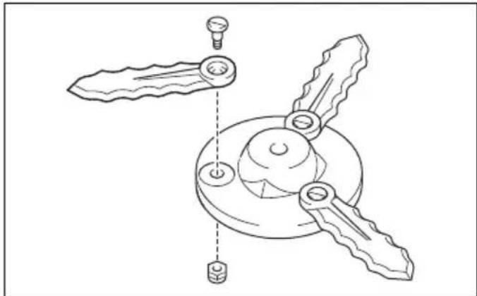
natural_image
Technical line drawing of a mechanical component with three blades and a central hub (no text or symbols)33 015450
ENGLISH (Original instructions)
Explanation of general view
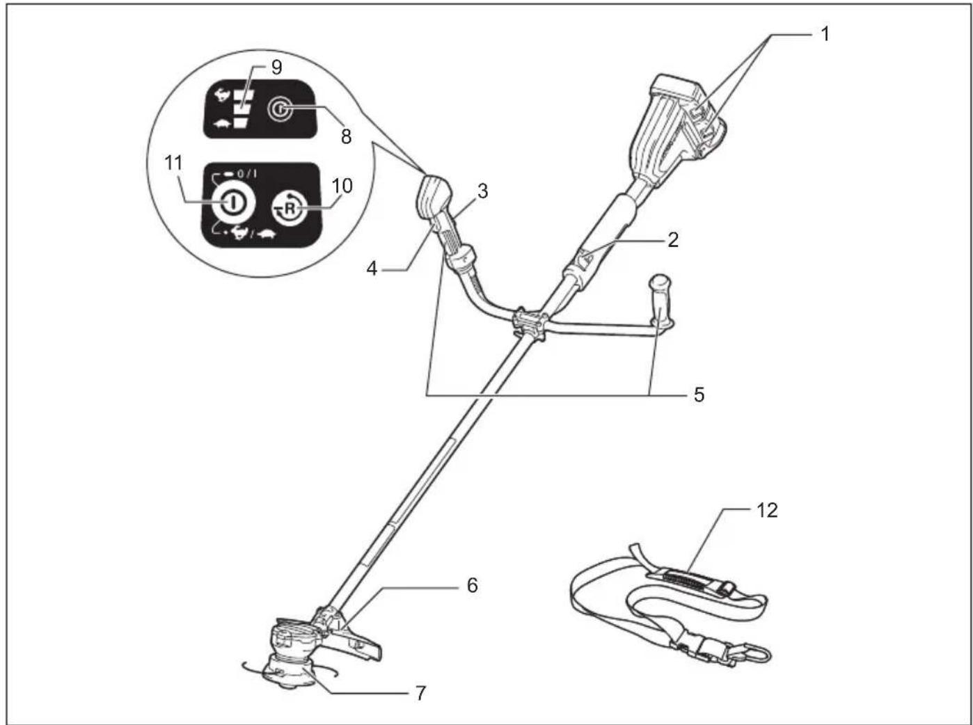
| 1. Battery cartridge | 14. Button | 27. Clamp washer |
| 2. Hanger (suspension point) | 15. Battery indicator | 28. Metal blade |
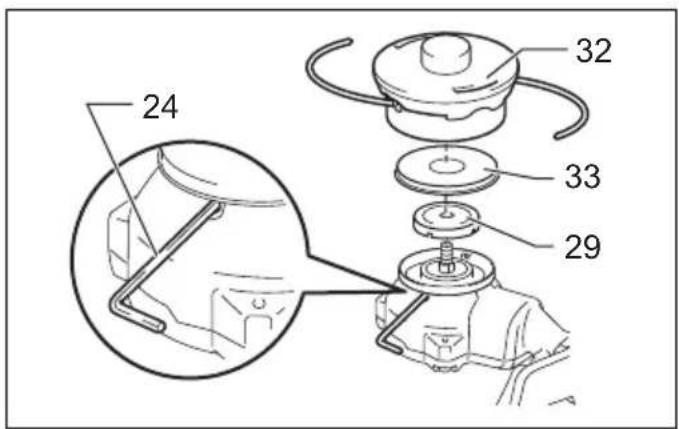
| 3. Lock-off lever | 16. Check button | 29. Receive washer |
| 4. Switch trigger | 17. Most effective cutting area | 30. Box driver |
| 5. Grip | 18. Handle | 31. Tighten |
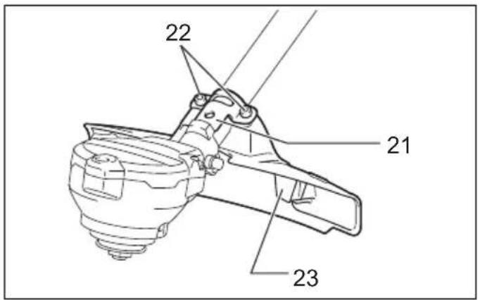
| 6. Protector (cutting tool guard) | 19. Screw | 32. Nylon cutting head |
| 7. Cutting tool | 20. Handle clamp | 33. Metal guard |
| 8. Power lamp | 21. Clamp | 34. Plastic blade |
| 9. Speed indicator | 22. Bolt | 35. Buckle |
| 10. Reverse button | 23. Cutter | 36. Hook |
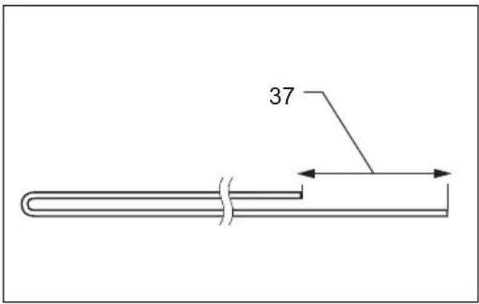
| 11. Main power button | 24. Hex wrench | 37. 80-100 mm |
| 12. Shoulder harness | 25. Nut | |
| 13. Red indicator | 26. Cup |
SPECIFICATIONS
| Model DUR365U | ||||
| Type of handle Bike handle | ||||
| No load speed 3,500/5,300/6 | 500 min | -1 | ||
| Overall length (without cutting tool) 1,754 mm | ||||
| Applicable cutting tool (country specific) | Metal blade Nylon | cutting head Plastic blade | ||
| Cutting diameter 230 mm 350 | mm 255 mm | |||
| Rated voltage D.C. 36 V | ||||
| Standard battery cartridge | BL1815N/BL1820 | BL1830/BL1840/BL1850 | ||
| Net weight (with metal blade) | 4.7 kg | 5.2 kg | ||
- Due to our continuing program of research and development, the specifications herein are subject to change without notice.
- Specifications and battery cartridge may differ from country to country.
- Weight, with battery cartridge, according to EPTA-Procedure 01/2003
| Noise | Sound pressure level average | Sound power level average | Applicable standard | |
| LPA (dB (A)) | LWA (dB (A)) | Uncertainty K (dB (A)) | ||
| Metal blade | 75 | 86 | 0.4 | 2000/14/EC |
| Plastic blade | 83 | 92.8 | 0.6 | |
| Nylon cutting head | 77 | 90 | 2.2 | |
- Even if the sound pressure level listed above is 80 dB (A) or less, the level under working may exceed 80 dB (A). Wear ear protection.
| Vibration | Left hand | Right hand | Applicable standard | ||
| ah (m/s2) | Uncertainty K ( m/s2 ) | ah (m/s2) | Uncertainty K ( m/s2 ) | ||
| Metal blade | ≤ 2.5 | 1.5 | ≤ 2.5 | 1.5 | EN786 |
| Plastic blade | ≤ 2.5 | 1.5 | ≤ 2.5 | 1.5 | |
| Nylon cutting head | ≤ 2.5 | 1.5 | ≤ 2.5 | 1.5 | |
ENG901-1
- The declared vibration emission value has been measured in accordance with the standard test method and may be used for comparing one tool with another.
- The declared vibration emission value may also be used in a preliminary assessment of exposure.
WARNING:
- The vibration emission during actual use of the power tool can differ from the declared emission value depending on the ways in which the tool is used.
- Be sure to identify safety measures to protect the operator that are based on an estimation of exposure in the actual conditions of use (taking account of all parts
of the operating cycle such as the times when the tool is switched off and when it is running idle in addition to the trigger time).
Symbols END119-1
The following show the symbols used for the equipment.
Be sure that you understand their meaning before use.

Take particular care and attention.


Read instruction manual.

Danger; be aware of thrown objects.

The distance between the tool and bystanders must be at least 15 m.

Keep bystanders away.

Keep distance at least 15 m.

Avoid kickback.

Wear a helmet, goggles and ear protection.

Wear protective gloves.

Wear sturdy boots with nonslip soles. Steeltoed safety boots are recommended.

Do not expose to moisture.

Top permissible tool speed.

Top permissible tool speed.

Cd Ni-MH Li-ion
Only for EU countries
Do not dispose of electric equipment or battery pack together with household waste material!
In observance of the European Directives, on Waste Electric and Electronic Equipment and Batteries and Accumulators and Waste Batteries and Accumulators and their implementation in accordance with national laws, electric equipment and batteries and battery pack(s) that have reached the end of their life must be collected separately and returned to an environmentally compatible recycling facility.
For European countries only ENH114-1-V3
EC Declaration of Conformity
Makita declares that the following Machine(s):
Designation of Machine:
Cordless Grass Trimmer
Model No./Type: DUR365U
Specifications: see "SPECIFICATIONS" table.
Conforms to the following European Directives:
2000/14/EC, 2006/42/EC
They are manufactured in accordance with the following standard or standardized documents:
The technical file in accordance with 2006/42/EC is available from:
Makita, Jan-Baptist Vinkstraat 2, 3070, Belgium
ENH115-1-V1
The conformity assessment procedure required by Directive 2000/14/EC was in Accordance with annex V.
With metal blade
Measured sound power level 86 dB (A)
Guaranteed sound power level 86 dB (A)
Plastic blade
Measured sound power level 92.8 dB (A)
Guaranteed sound power level 93 dB (A)
ENH115-1-V1
The conformity assessment procedure required by Directive 2000/14/EC was in Accordance with annex VI. Notified Body:
TÜV Rheinland LGA Products GmbH
Tillystraße 2
90431 Nürnberg, Germany
Identification number 0197
With nylon cutting head
Measured sound power level 90 dB (A)
Guaranteed sound power level 92 dB (A)
-
- 2015
Yasushi Fukaya
Director
Makita, Jan-Baptist Vinkstraat 2, 3070, Belgium
IMPORTANT SAFETY INSTRUCTIONS GEB068-6
WARNING! Read all safety warnings and all instructions. Failure to follow the warnings and instructions may result in electric shock, fire and/or serious injury.
Save all warnings and instructions for future reference.
Intended use
- The cordless grass trimmer/brushcutter/string trimmer is only intended for cutting grass, weeds, bushes and undergrowth. It should not be used for any other purpose such as edging or hedge cutting as this may cause injury.
General instructions
- Never allow people unfamiliar with these instructions, people (including children) with reduced physical, sensory or mental capabilities, or lack of experience and knowledge to use the tool. Children should be supervised to ensure that they do not play with the tool.
- Before starting the tool, read this instruction manual to become familiar with the handling of the tool.
- Do not lend the tool to a person with insufficient experience or knowledge regarding handling of brushcutters and string trimmers.
- When lending the tool, always attach this instruction manual.
- Handle the tool with the utmost care and attention.
- Never use the tool after consuming alcohol or drugs, or if feeling tired or ill.
- Never attempt to modify the tool.
- Follow the regulations about handling of brushcutters and string trimmers in your country.
Personal protective equipment (Fig. 1)
- Wear safety helmet, protective goggles and protective gloves to protect yourself from flying debris or falling objects.
- Wear ear protection such as ear muffs to prevent hearing loss.
- Wear proper clothing and shoes for safe operation, such as a work overall and sturdy, non-slip shoes. Do not wear loose clothing or jewelry. Loose clothes, jewelry or long hair can be caught in moving parts.
- When touching the cutting blade, wear protective gloves. Cutting blades can cut bare hands severely.
Work area safety
- Operate the tool under good visibility and daylight conditions only. Do not operate the tool in darkness or fog.
- Do not operate the tool in explosive atmospheres, such as in the presence of flammable liquids, gases or dust. The tool creates sparks which may ignite the dust or fumes.
- During operation, never stand on an unstable or slippery surface or a steep slope. During the cold season, beware of ice and snow and always ensure secure footing.
- During operation, keep bystanders or animals at least 15 m away from the tool. Stop the tool as soon as someone approaches.
- Before operation, examine the work area for stones or other solid objects. They can be thrown or cause dangerous kickback and result in serious injury and/or property damage.
- WARNING: Use of this product can create dust containing chemicals which may cause respiratory or other illnesses. Some examples of these chemicals are compounds found in pesticides, insecticides, fertilizers and herbicides. Your risk from these exposures varies, depending on how often you do this type of work. To reduce your exposure to these chemicals: work in a well ventilated area, and work with approved safety equipment, such as those dust masks that are specially designed to filter out microscopic particles.
Electrical and battery safety
- Do not expose the tool to rain or wet conditions. Water entering the tool will increase the risk of electric shock.
- Do not use the tool if the switch does not turn it on and off. Any tool that cannot be controlled with the switch is dangerous and must be repaired.
- Prevent unintentional starting. Ensure the switch is in the off-position before installing a battery pack, picking up or carrying the tool. Carrying the tool with your finger on the switch or energising the tool that have the switch on invites accidents.
- Recharge only with the charger specified by the manufacturer. A charger that is suitable for one type of battery pack may create a risk of fire when used with another battery pack.
- Use the tool only with specifically designated battery packs. Use of any other battery packs may create a risk of injury and fire.
- When battery pack is not in use, keep it away from other metal objects, like paper clips, coins, keys, nails, screws or other small metal objects, that can make a connection from one terminal to another. Shorting the battery terminals together may cause burns or a fire.
- Under abusive conditions, liquid may be ejected from the battery; avoid contact. If contact accidentally occurs, flush with water. If liquid contacts eyes, seek medical help. Liquid ejected from the battery may cause irritation or burns.
Putting into operation
- Before assembling or adjusting the tool, remove the battery cartridge.
- Before handling the cutter blade, wear protective gloves.
- Before installing the battery cartridge, inspect the tool for damages, loose screws/nuts or improper assembly. Sharpen blunt cutter blade. If the cutter blade is bent or damaged, replace it. Check all control levers and switches for easy action. Clean and dry the handles.
- Never attempt to switch on the tool if it is damaged or not fully assembled. Otherwise serious injury may result.
- Adjust the shoulder harness and hand grip to suit the operator's body size.
- When inserting a battery cartridge, keep the cutting attachment clear of your body and other object, including the ground. It may rotate when starting and may cause injury or damage to the tool and/or property.
- Remove any adjusting key, wrench or blade cover before turning the tool on. An accessory left attached to a rotating part of the tool may result in personal injury.
Operation
- In the event of an emergency, switch off the tool immediately.
- If you feel any unusual condition (e.g. noise, vibration) during operation, switch off the tool. Do not use the tool until the cause is recognized and solved.
-
The cutting attachment continues to rotate for a short period after turning the tool off. Don't rush to contact the cutting attachment.
-
During operation, use the shoulder harness. Keep the tool on your right side firmly.
- Do not overreach. Keep proper footing and balance at all times. Watch for hidden obstacles such as tree stumps, roots and ditches to avoid stumbling.
- Never work on a ladder or tree to avoid loss of control.
- If the tool gets heavy impact or fall, check the condition before continuing work. Check the controls and safety devices for malfunction. If there is any damage or doubt, ask our authorized service center for the inspection and repair.
- Do not touch the gear case. The gear case becomes hot during operation.
- Take a rest to prevent loss of control caused by fatigue. We recommend taking a 10 to 20-minute rest every hour.
- When you leave the tool, even if it is a short time, always remove the battery cartridge. The unattended tool with the battery cartridge installed may be used by unauthorized person and cause serious accident.
- If grass or branches get caught between the cutting attachment and guard, always turn the tool off and remove the battery cartridge before cleaning. Otherwise the cutting attachment may rotate unintentionally and cause serious injury.
- If the cutting attachment hits stones or other hard objects, immediately turn the tool off. Then remove the battery cartridge and inspect the cutting attachment.
- Check the cutting attachment frequently during operation for cracks or damages. Before the inspection, remove the battery cartridge and wait until the cutting attachment stops completely. Replace damaged cutting attachment immediately, even if it has only superficial cracks.
- Never cut above waist height.
- Before starting the cutting operation, wait until the cutting attachment reaches a constant speed after turning the tool on.
- When using metal blades, swing the tool evenly in half-circle from right to left, like using a scythe.
- Hold the tool by insulated gripping surfaces only, because the cutter blade may contact hidden wiring. Cutter blades contacting a "live" wire may make exposed metal parts of the tool "live" and could give the operator an electric shock.
Cutting attachments
- Use an applicable cutting attachment for the job in hand.
– Nylon cutting heads (string trimmer heads) are suitable for trimming lawn grass.
- Metal blades are suitable for cutting weeds, high grasses, bushes, shrubs, underwood, thicket, and the like.
- Never use other blades including metal multi-piece pivoting chains and flail blades. It may result in serious injury.
- Always use the cutting attachment guard properly suited for the cutting attachment used.
- When using metal blades, avoid "kickback" and always prepare for an accidental kickback. See the section "Kickback."
- When not in use, attach the blade cover onto the blade. Remove the cover before operation.
Kickback (Blade thrust)
- Kickback (blade thrust) is a sudden reaction to a caught or bound cutting blade. Once it occurs, the tool is thrown sideway or toward the operator at great force and it may cause serious injury.
- Kickback occurs particularly when applying the blade segment between 12 and 2 o'clock to solids, bushes and trees with 3 cm or larger diameter. (Fig. 2)
-
To avoid kickback: (Fig. 3)
-
Apply the segment between 8 and 11 o'clock.
- Never apply the segment between 12 and 2 o'clock.
- Never apply the segment between 11 and 12 o'clock and between 2 and 5 o'clock, unless the operator is well trained and experienced and does it at his/her own risk.
- Never use cutting blades close to solids, such as fences, walls, tree trunks and stones.
- Never use cutting blades vertically, for such operations as edging and trimming hedges.
Vibration
- People with poor circulation who are exposed to excessive vibration may experience injury to blood vessels or the nervous system. Vibration may cause the following symptoms to occur in the fingers, hands or wrists: "Falling asleep" (numbness), tingling, pain, stabbing sensation, alteration of skin color or of the skin. If any of these symptoms occur, see a physician!
- To reduce the risk of "white finger disease", keep your hands warm during operation and well maintain the tool and accessories.
Transport
- Before transporting the tool, turn it off and remove the battery cartridge. Attach the cover to the cutting blade.
- When transporting the tool, carry it in a horizontal position by holding the shaft.
- When transporting the tool in a vehicle, properly secure it to avoid turnover. Otherwise damage to the tool and other baggage may result.
Maintenance
- Have your tool serviced by our authorized service center, always using only genuine replacement parts. Incorrect repair and poor maintenance can shorten the life of the tool and increase the risk of accidents.
- Before doing any maintenance or repair work or cleaning the tool, always turn it off and remove the battery cartridge.
- Always wear protective gloves when handling the cutting blade.
- Always clean dust and dirt off the tool. Never use gasoline, benzine, thinner, alcohol or the like for the purpose. Discoloration, deformation or cracks of the plastic components may result.
- After each use, tighten all screws and nuts.
- Do not attempt any maintenance or repair not described in the instruction manual. Ask our authorized service center for such work.
- Always use our genuine spare parts and accessories only. Using parts or accessories supplied by a third
party may result in the tool breakdown, property damage and/or serious injury.
- Request our authorized service center to inspect and maintain the tool at regular interval.
Storage
- Before storing the tool, perform full cleaning and maintenance. Remove the battery cartridge. Attach the cover to the cutting blade.
- Store the tool in a dry and high or locked location out of reach of children.
- Do not prop the tool against something, such as a wall. Otherwise it may fall suddenly and cause an injury.
First aid
- Always have a first-aid kit close by. Immediately replace any item taken from the first aid kit.
- When asking for help, give the following information:
- Place of the accident
- What happened
– Number of injured persons
– Nature of the injury - Your name
SAVE THESE INSTRUCTIONS.
WARNING:
DO NOT let comfort or familiarity with product (gained from repeated use) replace strict adherence to safety rules for the subject product. MISUSE or failure to follow the safety rules stated in this instruction manual may cause serious personal injury.
IMPORTANT SAFETY INSTRUCTIONS ENC007-8
FOR BATTERY CARTRIDGE
- Before using battery cartridge, read all instructions and cautionary markings on (1) battery charger, (2) battery, and (3) product using battery.
- Do not disassemble battery cartridge.
- If operating time has become excessively shorter, stop operating immediately. It may result in a risk of overheating, possible burns and even an explosion.
- If electrolyte gets into your eyes, rinse them out with clear water and seek medical attention right away. It may result in loss of your eyesight.
-
Do not short the battery cartridge:
(1) Do not touch the terminals with any conductive material.
(2) Avoid storing battery cartridge in a container with other metal objects such as nails, coins, etc.
(3) Do not expose battery cartridge to water or rain.
A battery short can cause a large current flow, overheating, possible burns and even a breakdown. -
Do not store the tool and battery cartridge in locations where the temperature may reach or exceed 50irc C ( 122irc F).
- Do not incinerate the battery cartridge even if it is severely damaged or is completely worn out. The battery cartridge can explode in a fire.
- Be careful not to drop or strike battery.
- Do not use a damaged battery.
- Follow your local regulations relating to disposal of battery.
SAVE THESE INSTRUCTIONS.
Tips for maintaining maximum battery life
- Charge the battery cartridge before completely discharged.
Always stop tool operation and charge the battery cartridge when you notice less tool power. - Never recharge a fully charged battery cartridge. Overcharging shortens the battery service life.
- Charge the battery cartridge with room temperature at 10irc C - 40irc C ( 50irc F - 104irc F). Let a hot battery cartridge cool down before charging it.
- Charge the battery cartridge once in every six months if you do not use it for a long period of time.
PARTS DESCRIPTION (Fig. 4)
FUNCTIONAL DESCRIPTION
WARNING:
• Always be sure that the tool is switched off and the battery cartridge is removed before adjusting or checking function on the tool. Failure to switch off and remove the battery cartridge may result in serious personal injury from accidental start-up.
Installing or removing battery cartridge
CAUTION:
- Always switch off the tool before installing or removing of the battery cartridge.
- Hold the tool and the battery cartridge firmly when installing or removing battery cartridge. Failure to hold the tool and the battery cartridge firmly may cause them to slip off your hands and result in damage to the tool and battery cartridge and a personal injury.
To remove the battery cartridge, slide it from the tool while sliding the button on the front of the cartridge. (Fig. 5) To install the battery cartridge, align the tongue on the battery cartridge with the groove in the housing and slip it into place. Insert it all the way until it locks in place with a little click. If you can see the red indicator on the upper side of the button, it is not locked completely.
CAUTION:
- Always install the battery cartridge fully until the red indicator cannot be seen. If not, it may accidentally fall out of the tool, causing injury to you or someone around you.
- Do not install the battery cartridge forcibly. If the cartridge does not slide in easily, it is not being inserted correctly.
NOTE:
• The tool does not work with only one battery cartridge.
Tool/battery protection system
The tool is equipped with a tool/battery protection system. This system automatically cuts off power to the motor to extend tool and battery life.
The tool will automatically stop during operation if the tool or battery is placed under one of the following conditions. In some conditions, the indicators light up.
Overload protection
015586
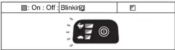
If the tool is overloaded by entangled weeds or other debris, the tool stops automatically, and all of the speed indicators blink. In this situation, turn the tool off and stop the application that caused the tool to become overloaded. Then turn the tool on to restart.
Overheat protection for tool

015585
When the tool is overheated, the tool stops automatically, and all of the speed indicators and the battery indicator blink about 60 seconds. In this situation, let the tool cool down before turning the tool on again.
Overdischarge protection
When the battery capacity becomes low, the tool stops automatically. If the tool does not operate even when the switches are operated, remove the batteries from the tool and charge the batteries.
Remaining battery capacity indication (Fig. 6)
Press the check button to make the battery indicators show the remaining battery capacities. The battery indicators correspond to each battery.
Remaining battery capacity indication
| Battery indicator status Remaining | battery capacity | ||
| : On : Off : Blinking | |||
| 50% - 100% | |||
| 20% - 50% | |||
| 0% - 20% | |||
| Charge the battery | |||
015452
Power switch action
WARNING:
- Before inserting the battery cartridge into the tool, always check to see that the switch trigger actuates properly and returns to the "OFF" position when released. Operating a tool with a switch that does not actuate properly can lead to loss of control and serious personal injury.
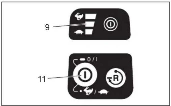
Press and hold the main power button for some seconds to turn on the tool. (Fig. 7)
To turn off the tool, press and hold the main power button again.
To prevent the switch trigger from being accidentally pulled, a lock-off lever is provided.
To start the tool, grasp the right grip (the lock-off lever is released by the grasp) and then pull the switch trigger. To stop the tool, release the switch trigger. (Fig. 8)
NOTE:
- The tool is automatically turned off after the tool is left one minute without any operations.
Speed adjusting (Fig. 9)
You can adjust the tool speed by tapping the main power button.
Each time you tap the main power button, one of the speed indicator lights up in order of Turtle (→middle, Rabbit (→
is for low speed and for high speed, and the middle indicator for middle speed.
Reverse button for debris removal
WARNING:
- Switch off the tool and remove the battery cartridge before you remove entangled weeds or debris which the reverse rotation function can not remove. Failure to switch off and remove the battery cartridge may result in serious personal injury from accidental start-up.
This tool has a reverse button to change the direction of rotation. It is only for removing weeds and debris entangled in the tool. (Fig. 10)
To reverse the rotation, tap the reverse button and pull the trigger when the tool's head is stopped. The power lamp starts blinking, and the tool's head rotates in reverse direction when you pull the switch trigger.
To return to regular rotation, release the trigger and wait until the tool's head stops.
NOTE:
- During the reverse rotation, the tool operates only for a short period of time and then automatically stops.
- Once the tool is stopped, the rotation returns to regular direction when you start the tool again.
- If you tap the reverse button while the tool's head is still rotating, the tool comes to stop and to be ready for reverse rotation.
Nylon cutting head (optional accessory)
NOTICE:
- The bump feed will not operate properly if the head is not rotating.
The nylon cutting head is a dual string trimmer head provided with a bump & feed mechanism.
To cause the nylon cord to feed out, the cutting head should be bumped against the ground while rotating. (Fig. 11)
NOTE:
If the nylon cord does not feed out while bumping the head, rewind/replace the nylon cord by following the procedures described under "Maintenance."
ASSEMBLY
WARNING:
• Always be sure that the tool is switched off and battery cartridge is removed before carrying out any work on the tool. Failure to switch off and remove the battery cartridge may result in serious personal injury from accidental start-up.
- Never start the tool unless it is completely assembled. Operation of the tool in a partially assembled state may result in serious personal injury from accidental start-up.
Installing the handle
Insert the shaft of the handle into the grip. Align the screw hole in the grip with the one in the shaft. Tighten the screw securely. (Fig. 12)
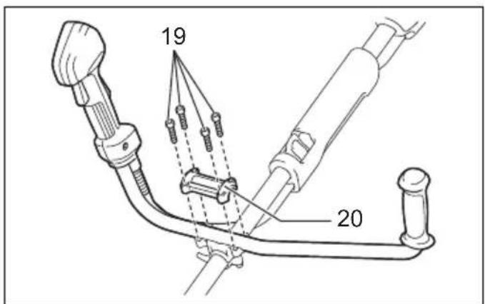
Place handle between handle clamp and handle holder. Adjust the handle to an angle that provides a comfortable working position and then secure by firmly hand-tightening knob. (Fig. 13)
Installing the guard
WARNING:
- Never use the tool without the guard illustrated in place. Failure to do so can cause serious personal injury.
• Always use the tool with the approved combination of the safety equipments. Otherwise contact with a cutting tool may cause serious injury. - Permitted combination for the cutting tool and the guard may differ from country to country. Follow your region's regulations.
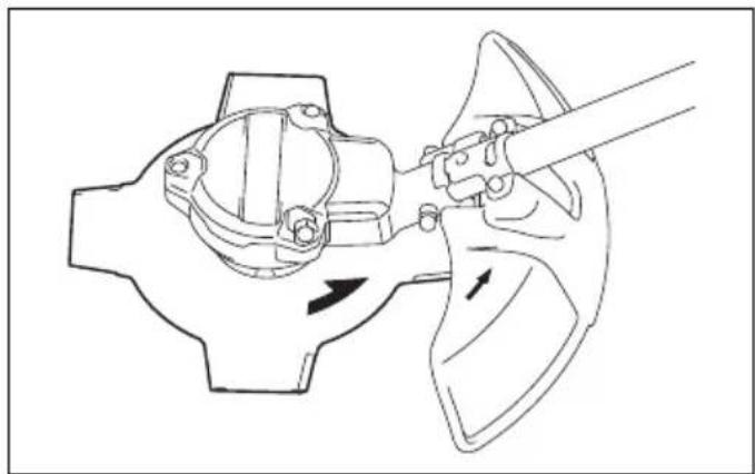
For metal blade (Fig. 14 & 15)
For nylon cutting head or plastic blade
CAUTION:
• Take care not to injure yourself on the cutter for cutting the nylon cord when installing nylon cutting head or plastic blade. (Fig. 16)
Align the clamp on the pipe with the protector. And tighten them with bolts. (Fig. 17)
Installing the metal blade (optional accessory)
WARNING:
- The outside diameter of the metal blade must be 230 mm. Never use any blade exceeding 230 mm in outside diameter.
CAUTION:
- The metal blade must be well polished, free of cracks or breakage. Polish or replace the metal blade every three hours of operation.
• Always wear gloves when handling the metal blade. - Always attach the blade cover when the tool is not in use or is being transported.
- The metal blade-fastening nut (with spring washer) wears out in course of time. If there appears any wear or deformation on the spring washer, replace the nut. Ask your local authorized service center to order it.
- Replace the cup in case of crack or breakage due to attrition.
NOTICE:
- Be sure to use genuine Makita metal blade.
Turn the tool upside down so that you can replace the metal blade easily.
Mount the metal blade onto the shaft so that the guide of the receive washer fits in the arbor hole in the metal blade. Install the clamp washer and secure the metal blade with the hex nut with 13 to 23 Nm of tightening torque during holding the receive washer with hex wrench. (Fig. 18)
To dismount the metal blade, insert the hex wrench through the hole on the protector cover and the gear case. Rotate the receive washer until it is locked with the hex wrench. Loosen the hex nut (left-hand thread) with the socket wrench and remove the nut, clamp washer and hex wrench. (Fig. 19)
Make sure that the blade is the left way up. (Fig. 20)
Installing nylon cutting head or plastic blade (optional accessory)
CAUTION:
- If the nylon cutting head/plastic blade accidentally impacts a rock or hard object during operation, stop the tool and inspect for any damage. If the nylon cutting head/plastic blade is damaged, replace it immediately. Use of a damaged cutting tool could result in serious personal injury.
NOTICE:
- Be sure to use genuine Makita nylon cutting head/plastic blade.
Turn the tool upside down so that you can replace the nylon cutting head easily.
Insert the hex wrench through the hole on the motor housing and rotate the receive washer until it is locked with the hex wrench. Place the nylon cutting head/plastic blade onto the threaded spindle directly and tighten it by turning it counterclockwise. Remove the hex wrench.
To remove the nylon cutting head/plastic blade, turn it clockwise while holding the receive washer with the hex wrench. (Fig. 21 & 22)
Hex wrench storage (Fig. 23)
When not in use, store the hex wrench as shown in the figure to keep it from being lost.
OPERATION
Correct handling of tool

WARNING:
- Be extremely careful to maintain control of the tool at all times. Do not allow the tool to be deflected toward you or anyone in the work vicinity. Failure to keep control of the tool could result in serious injury to the bystander and the operator.
Correct posture

WARNING:
- Always hold the both grips firmly and position the tool on your right-hand side so that the shaft of the left handle is always in front of your body. Correct positioning of the tool allows for maximum control and will reduce the risk of serious personal injury caused by kickback.
Fit the shoulder harness and hang the tool firmly on your right side so that the shaft of the left handle is always ahead of you. (Fig. 24)
Attachment of shoulder harness
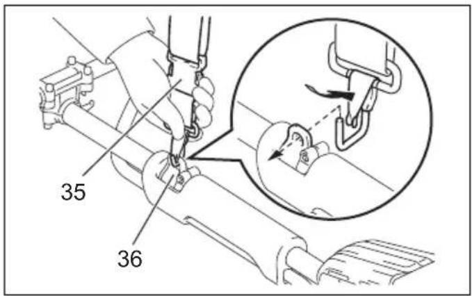
Wear the shoulder harness on your left shoulder. Make sure that the buckle cannot be taken off with pulling it off. Hang the tool as shown. (Fig. 25)
The buckle is provided with a means of quick release. Simply squeeze the sides of the buckle to release the tool. (Fig. 26)
Adjustment of the hanger position and shoulder harness
To change the hanger position, loosen the fixing screw on the hanger with the supplied wrench and then move the hanger and the cushion. The cushion can be moved easily by twisting it.
MAINTENANCE

WARNING:
- Always be sure that the tool is switched off and battery cartridge is removed before attempting to perform inspection or maintenance on the tool. Failure to switch off and remove the battery cartridge may result in serious personal injury from accidental start-up.
NOTICE:
Never use gasoline, benzine, thinner, alcohol or the like. Discoloration, deformation or cracks may result.
Replacing the nylon cord

WARNING:
- Make sure that the cover of the nylon cutting head is secured to the housing properly as described below. Failure to properly secure the cover may cause the nylon cutting head to fly apart resulting in serious personal injury.
Take off cover from housing, pressing two latches which are slotted section oppositely on side of housing. (Fig. 27) Cut a nylon line in 3-6 m. Fold the cutting line in two halves, leave one of half longer 80-100 mm than another. (Fig. 28)
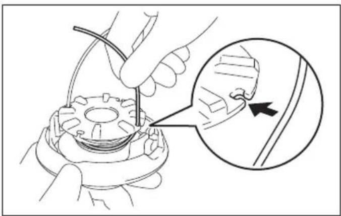
Hook the middle of the new nylon cord to the notch located at the center of the spool between the 2 channels provided for the nylon cord.
Wind both ends firmly around the spool in the direction marked on the head for left hand direction indicated by LH. (Fig. 29)
Wind all but about 100 mm of the cords, leaving the ends temporarily hooked through a notch on the side of the spool. (Fig. 30)
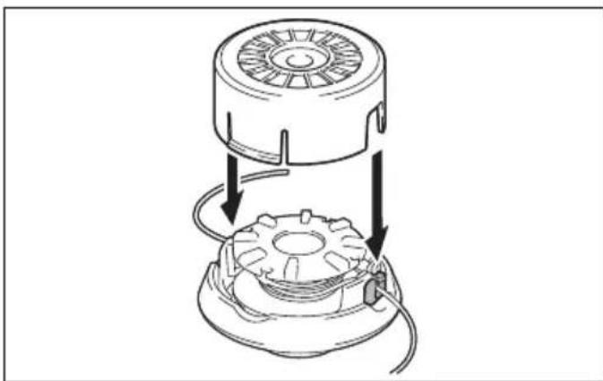
Mount the spool on the cover so that the grooves and protrusions on the spool match up with those on the cover. Now, unhook the ends of the cord from their temporary position and feed the cords through the eyelets to come out of the cover. (Fig. 31)
Align the protrusion on the underside of the cover with the slots of the eyelets. Then push the cover firmly onto the housing to secure it. Make sure the latches fully spread in the cover. (Fig. 32)
Replacing the blade for plastic blade (Fig. 33)
Replace the blade when it is worn out or broken.
To maintain product SAFETY and RELIABILITY, repairs, any other maintenance or adjustment should be performed by Makita Authorized Service Centers, always using Makita replacement parts.
TROUBLE SHOOTING
Before asking for repairs, conduct your own inspection first. If you find a problem that is not explained in the manual, do not attempt to dismantle the tool. Instead, ask Makita Authorized Service Centers, always using Makita replacement parts for repairs.
| Malfunction status Cause | Action | |
| Motor does not run. | Battery cartridges are not installed. Install the battery cartridges. | |
| Battery problem (under voltage) | Recharge the battery cartridge. If recharging is not effective, replace battery cartridge. | |
| The drive system does not work correctly. | Ask your local authorized service center for repair. | |
| Motor stops running after a little use. | Rotation is in reverse. | Change the direction of rotation with the reversing switch. |
| Battery's charge level is low. | Recharge the battery cartridge. If recharging is not effective, replace battery cartridge. | |
| Overheating. Stop using of tool to allow it to cool down. | ||
| It does not reach maximum RPM. | Battery is installed improperly. | Install the battery cartridge as described in this manual. |
| Battery power is dropping. | Recharge the battery cartridge. If recharging is not effective, replace battery cartridge. | |
| The drive system does not work correctly. | Ask your local authorized service center for repair. | |
| Cutting tool does not rotate: stop the machine immediately! | Foreign object such as a branch is jammed between the guard and the nylon cutting head. | Remove the foreign object. |
| Cutter blade fastening nut is loose. | Tighten the nut properly as described in this manual. | |
| The cutter blade is bent. Replace the cutter blade. | ||
| The drive system does not work correctly. | Ask your local authorized service center for repair. | |
| Abnormal vibration: stop the machine immediately! | One end of the nylon cord has been broken. | Bump the nylon cutting head against the ground while it is rotating to cause the cord to feed. |
| The cutter blade is bent, cracked or worn. | Replace the cutter blade. | |
| Cutter blade fastening nut is loose. | Tighten the nut properly as described in this manual. | |
| Cutter blade is fastened improperly. | ||
| The drive system does not work correctly. | Ask your local authorized service center for repair. | |
| Cutting tool and motor cannot stop: Remove the battery immediately! | Electric or electronic malfunction. | Remove the battery cartridge and ask your local authorized service center for repair. |
014837
OPTIONAL ACCESSORIES

CAUTION:
• These accessories or attachments are recommended for use with your Makita tool specified in this manual. The use of any other accessories or attachments might present a risk of injury to persons. Only use accessory or attachment for its stated purpose.
If you need any assistance for more details regarding these accessories, ask your local Makita Service Center.
- Cutter blade
- Nylon cutting head
- Nylon cord (cutting line)
- Plastic blade
• Protector assembly for nylon cutting - Protector assembly for cutter blade
- Makita genuine battery and charger
NOTE:
- Some items in the list may be included in the tool package as standard accessories. They may differ from country to country.
2000/14/EC, 2006/42/EC
⚠ WAARSCHUWING! Lees alle
2000/14/EC, 2006/42/EC
2000/14/EF, 2006/42/EF
2000/14/EK, 2006/42/EK
2000/14/EC, 2006/42/EC


- ENG901-1
- WARNING:
- Symbols END119-1
- EC Declaration of Conformity
- Makita declares that the following Machine(s):
- Conforms to the following European Directives:
- With metal blade
- Plastic blade
- With nylon cutting head
- IMPORTANT SAFETY INSTRUCTIONS GEB068-6
- Save all warnings and instructions for future reference.
- Intended use
- General instructions
- Personal protective equipment (Fig. 1)
- Work area safety
- Electrical and battery safety
- Putting into operation
- Operation
- Cutting attachments
- Kickback (Blade thrust)
- Vibration
- Transport
- Maintenance
- Storage
- First aid
- SAVE THESE INSTRUCTIONS.
- IMPORTANT SAFETY INSTRUCTIONS ENC007-8
- FOR BATTERY CARTRIDGE
- Tips for maintaining maximum battery life
- PARTS DESCRIPTION (Fig. 4)
- FUNCTIONAL DESCRIPTION
- Installing or removing battery cartridge
- CAUTION:
- NOTE:
- Tool/battery protection system
- Overdischarge protection
- Remaining battery capacity indication (Fig. 6)
- Power switch action
- Speed adjusting (Fig. 9)
- Reverse button for debris removal
- Nylon cutting head (optional accessory)
- NOTICE:
- ASSEMBLY
- Installing the handle
- Installing the guard
- For nylon cutting head or plastic blade
- Installing the metal blade (optional accessory)
- Installing nylon cutting head or plastic blade (optional accessory)
- Hex wrench storage (Fig. 23)
- Correct handling of tool
- Correct posture
- Attachment of shoulder harness
- Adjustment of the hanger position and shoulder harness
- Replacing the nylon cord
- Replacing the blade for plastic blade (Fig. 33)
- TROUBLE SHOOTING
- OPTIONAL ACCESSORIES
- ⚠ WAARSCHUWING! Lees alle
Brand : MAKITA
Model : DUR365UZ
Category : String Trimmer