
AutoCAD 2016 - Software AUTODESK - Free user manual and instructions
Find the device manual for free AutoCAD 2016 AUTODESK in PDF.


| Product Type | Computer-Aided Design (CAD) Software |
| Version | 2016 |
| Publisher | Autodesk |
| Category | Design & Engineering Software |
| Main Functions | 2D drafting, 3D modeling, annotation, parametric constraints, dynamic blocks, rendering |
| Supported Operating Systems | Windows 7 SP1, Windows 8.1, Windows 10 (64-bit) |
| Processor | Intel Pentium 4 or AMD Athlon 64 with SSE2 support |
| Memory (RAM) | 2 GB minimum, 4 GB recommended |
| Disk Space | 6 GB free space |
| Display Resolution | 1024x768 minimum, 1280x1024 recommended |
| Graphics Card | DirectX 10 capable graphics card (DirectX 11 recommended) |
| License Type | Commercial, Educational, or Trial |
| Language Support | Multiple languages (English, French, German, etc.) |
| File Formats | DWG, DXF, DWT, DWS, and others |
| Trial Period | 30-day free trial |
| Maintenance & Updates | Service packs and updates available from Autodesk |
| User Manual | Included with software, 42 pages PDF |
| Safety | No specific safety precautions; standard computer usage |
| Spare Parts & Repairability | Not applicable (software) |
| Dimensions & Weight | Not applicable (digital product) |
| Power Supply | Not applicable (software) |
Frequently Asked Questions - AutoCAD 2016 AUTODESK
User questions about AutoCAD 2016 AUTODESK
0 question about this device. Answer the ones you know or ask your own.
Ask a new question about this device
Download the instructions for your Software in PDF format for free! Find your manual AutoCAD 2016 - AUTODESK and take your electronic device back in hand. On this page are published all the documents necessary for the use of your device. AutoCAD 2016 by AUTODESK.
USER MANUAL AutoCAD 2016 AUTODESK
AutoCAD® 2016 Tutorial First Level 2D Fundamentals
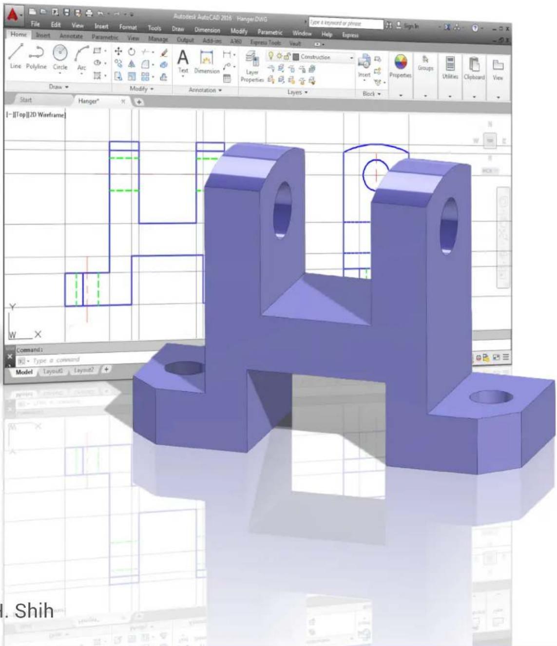
Randy H. Shih
Visit the following websites to learn more about this book:



Chapter 1 AutoCAD Fundamentals
Learning Objectives
◆ Create and Save AutoCAD drawing files
◆ Use the AutoCAD visual reference commands
- Draw, using the LINE and CIRCLE commands
◆ Use the ERASE command
♦ Define Positions using the Basic Entry methods
◆ Use the AutoCAD Pan Realtime option
AutoCAD Certified User Examination Objectives Coverage
This table shows the pages on which the objectives of the Certified User Examination are covered in Chapter 1.
Section 1: Controlling the Display in Drawings
Precision 1-6
Zoom Extent....1-7
Drawing LIMITS 1-6
Status Bar 1-10
GRID Display 1-10, 1-11
PAN Realtime 1-20
Section 2: Creating Basic Drawings
Format 1-5
Units Setup 1-5
LINE Command 1-8
Coordinates 1-8
Interactive Input Method....1-10
SNAP Option 1-12
World Space 1-15
User Coordinate System 1-15
World Coordinate System 1-15
UCS Icon Display 1-16
TTR, Circle 1-23
Relative Coordinate ....1-17
Coordinate Systems 1-17
Cartesian coordinate system 1-17
Absolute Coordinates ....1-17, 1-18
Positions, Defining ....1-18
LINE, Close Option ....1-19
CIRCLE Command 1-23
TTT, Circle 1-23
ARC Command ....1-33
Section 3: Manipulating Objects
ERASE Command 1-13
Selection Window 1-14
Introduction
Learning to use a CAD system is similar to learning a new language. It is necessary to begin with the basic alphabet and learn how to use it correctly and effectively through practice. This will require learning some new concepts and skills as well as learning a different vocabulary. Today, the majority of the Mechanical CAD systems are capable of creating three-dimensional solid models. Nonetheless, all CAD systems create designs using basic geometric entities and many of the constructions used in technical designs are based upon two-dimensional planar geometry. The method and number of operations that are required to accomplish the basic planar constructions are different from one system to another.
In order to become effective and efficient in using a CAD system, we must learn to create geometric entities quickly and accurately. In learning to use a CAD system, lines and circles are the first two, and perhaps the most important two, geometric entities that one should master the skills of creating and modifying. Straight lines and circles are used in almost all technical designs. In examining the different types of planar geometric entities, the importance of lines and circles becomes obvious. Triangles and polygons are planar figures bounded by straight lines. Ellipses and splines can be constructed by connecting arcs with different radii. As one gains some experience in creating lines and circles, similar procedures can be applied to create other geometric entities. In this chapter, the different ways of creating lines and circles in AutoCAD 2016 are examined.
Starting Up AutoCAD 2016
- Select the AutoCAD 2016 option on the Program menu or select the AutoCAD 2016 icon on the Desktop. Click Start Drawing to start a new drawing.
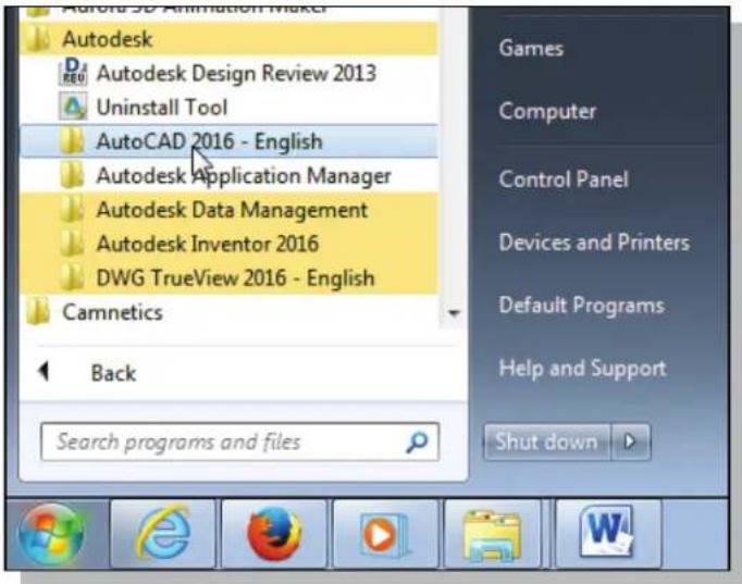

Once the program is loaded into memory, the AutoCAD 2016 main drawing screen will appear on the screen.
Note that AutoCAD automatically assigns generic names, Drawing X, as new drawings are created. In our example, AutoCAD opened the graphics window using the default system units and assigned the drawing name Drawing1.
![Autodesk AutoCAD 2016 DrawingL.dwg Type a keyword or phrase Home Insert Annotate Parametric View Manage Output Add-ins A360 Express Tools Line Polyline Circle Arc Text Dimension Layers Block Properties Groups Utilities Clipboard View Draw Modify Annotation Start Drawing1* Top[2D Wireframe] Command: Type a command Model Layout1 Layout2 MODEL](/content/2026/06/1272807/images/b3fb086dc2b5cc47ac28e611c0c80e1b4f3d3e1c2e0680a75bf1550aa74ec817.jpg)
- If necessary, click on the down-arrow in the Quick Access bar and select Show Menu Bar to display the AutoCAD Menu Bar. The Menu Bar provides access to all AutoCAD commands.


- To switch on the AutoCAD Coordinates Display, use the Customization option at the bottom right corner.


Drawing Units Setup
Every object we construct in a CAD system is measured in units. We should determine the system of units within the CAD system before creating the first geometric entities.

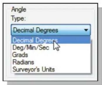
- Click on the Length Type option to display the different types of length units available. Confirm the Length Type is set to Decimal.
- In the Menu Bar select:
[Format] → [Units]
- The AutoCAD Menu Bar contains multiple pull-down menus where all of the AutoCAD commands can be accessed. Note that many of the menu items listed in the pull-down menus can also be accessed through the Quick Access toolbar and/or Ribbon panels.

-
On your own, examine the other settings that are available.
-
In the Drawing Units dialog box, set the Length Type to Decimal. This will set the measurement to the default English units, inches.
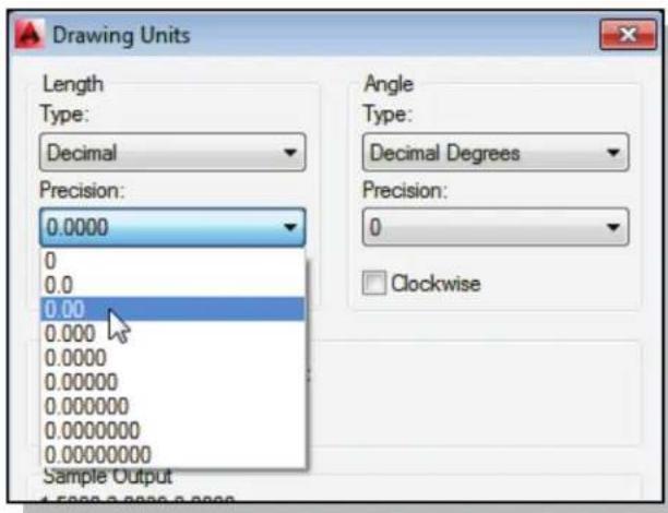
- Set the Precision to two digits after the decimal point as shown in the above figure.
- Pick OK to exit the Drawing Units dialog box.
![AUTODESK AutoCAD 2016 - [Format] → [Units] - 3](/content/2026/06/1272807/images/b206cc50e2b395b03ef91c175500b750e0777b77c9d39f4f8880ca6ba7ac5d4a.jpg)
Drawing Area Setup
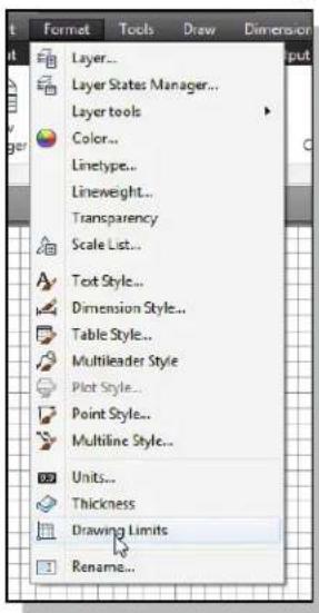
✿ Next, we will set up the Drawing Limits by entering a command in the command prompt area. Setting the Drawing Limits controls the extents of the display of the grid. It also serves as a visual reference that marks the working area. It can also be used to prevent construction outside the grid limits and as a plot option that defines an area to be plotted/printed. Note that this setting does not limit the region for geometry construction.
- In the Menu Bar select:
[Format] → [Drawing Limits]
- In the command prompt area, the message "Reset Model Space Limits: Specify lower left corner or [On/Off] <0.00,0.00>." is displayed. Press the ENTER key once to accept the default coordinates <0.00,0.00>.
![Reset Model space limits: - LIMITS Specify lower left corner or [ON OFF] <0.00,0.00>: Model Layout1 Layout2 59](/content/2026/06/1272807/images/b35ebeb7ee82d2669b5a0bebc679ff33d797edcde6d2712fa2dc47bc2edc7cf9.jpg)
- In the command prompt area, the message "Specify upper right corner <12.00,9.00>." is displayed. Press the ENTER key again to accept the default coordinates <12.00,9.00>.
![Specify lower left corner or [ON/OFF] <0.00,0.00>: LIMITS Specify upper right corner <12.00,9.00>: Model Layout1 Layout2 30](/content/2026/06/1272807/images/b76a4483d24b19339d93972c7e1ae992410c4ce5121318957bc3d4cd9eb03603.jpg)
- On your own, move the graphics cursor near the upper-right corner inside the drawing area and note that the drawing area is unchanged. (The Drawing Limits command is used to set the drawing area, but the display will not be adjusted until a display command is used.)
![Autodesk AutoCAD 2016 Drawing1.dwg File Edit View Insert Format Tools Draw Dimension Modify Home Insert An Line Polyline Circle Draw Start [ - ] [ Top ] [ 2D Wireframe ] Redraw Regen Regen All Zoom Pan SteeringWheels ShowMotion Orbit Camera Walk and Fly Clean Screen Ctrl+0 Viewports Named Views.. 3D Views Create Camera Realtime Previous Window Dynamic Scale Center Object In Out All Extents](/content/2026/06/1272807/images/b07ddfe588fd0fe5ca148d105262da65652b2334b7bc09b08862dce9dfaf15b1.jpg)
- Inside the Menu Bar area select: [View] → [Zoom] → [All]
The Zoom All command will adjust the display so that all objects in the drawing are displayed to be as large as possible. If no objects are constructed, the Drawing Limits are used to adjust the current viewport.
-
Move the graphics cursor near the upper-right corner inside the drawing area and note that the display area is updated.
-
Hit the function key [F7] once to turn off the display of the Grid lines.
![AutoCAD AutoCAD 2016 - Drawing1.dwg File Edit View Insert Format Tools Draw Dimension Modify Parametric Window Help Express Home Insert Annotate Parametric View Manage Output Add-ins A360 Express Tools Line Polyline Circle Arc Text Dimension Layer Properties Insert Properties Groups Utilities Clipboard View Draw Modify Annotation Layers Block Start Drawing1* [Top]2D Wireframe] Commands: world offs Type as command Model Layout1 Layout2 5.72, 4.24, 0.00 MODEL](/content/2026/06/1272807/images/f5b34a2729fcf8bc96d8c2b6ea5d4e639437c9c12aaa38c8e5b77d0a6cd177d3.jpg)
- Note that function key [F7] is a quick key, which can be used to quickly toggle on/off the grid display. Also, note the command prompt area can be positioned to dock below the drawing area or float inside the drawing area as shown.
Drawing Lines with the LINE Command
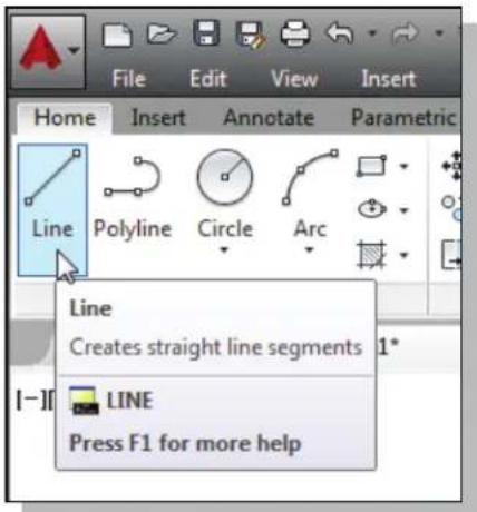
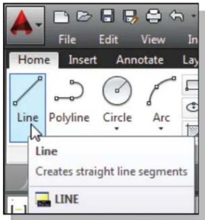
- Move the graphics cursor to the first icon in the Draw panel. This icon is the Line icon. Note that a brief description of the Line command appears next to the cursor.
-
Select the icon by clicking once with the left-mouse-button, which will activate the Line command.
-
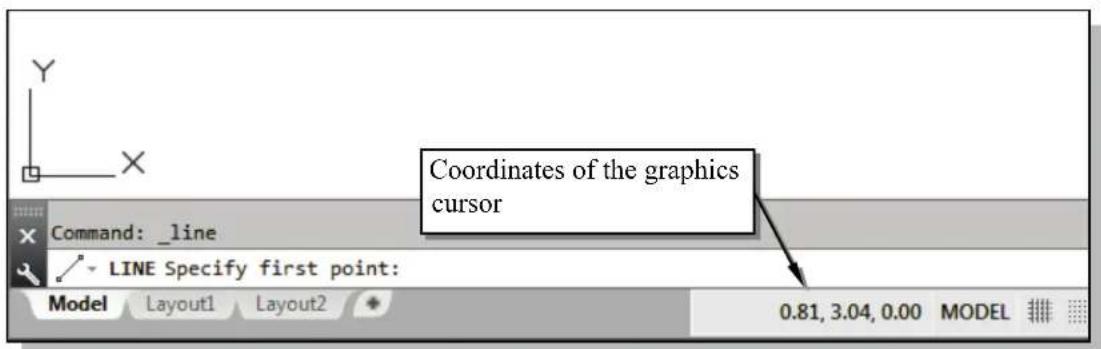
In the command prompt area, near the bottom of the AutoCAD drawing screen, the message “_line Specify first point:” is displayed. AutoCAD expects us to identify the starting location of a straight line. Move the graphics cursor inside the graphics window and watch the display of the coordinates of the graphics cursor at the bottom of the AutoCAD drawing screen. The three numbers represent the location of the cursor in the X, Y, and Z directions. We can treat the graphics window as if it was a piece of paper and we are using the graphics cursor as if it were a pencil with which to draw.

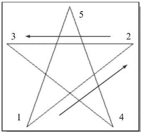
We will create a freehand sketch of a five-point star using the Line command. Do not be overly concerned with the actual size or accuracy of your freehand sketch. This exercise is to give you a feel for the AutoCAD 2016 user interface.
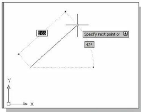
- We will start at a location about one-third from the bottom of the graphics window. Left-click once to position the starting point of our first line. This will be point 1 of our sketch. Next, move the cursor upward and toward the right side of point 1. Notice the rubber-band line that follows the graphics cursor in the graphics window. Left-click again (point 2) and we have created the first line of our sketch.

-
Move the cursor to the left of point 2 and create a horizontal line about the same length as the first line on the screen.
-
Repeat the above steps and complete the freehand sketch by adding three more lines (from point 3 to point 4, point 4 to point 5, and then connect to point 5 back to point 1).

- Notice that the Line command remains activated even after we connected the last segment of the line to the starting point (point 1) of our sketch. Inside the graphics window, click once with the right-mouse-button and a popup menu appears on the screen.
- Select Enter with the left-mouse-button to end the Line command. (This is equivalent to hitting the [ENTER] key on the keyboard.)
- Move the cursor near point 2 and point 3, and estimate the length of the horizontal line by watching the displayed coordinates for each point.
Visual Reference
The method we just used to create the freehand sketch is known as the interactive method, where we use the cursor to specify locations on the screen. This method is perhaps the fastest way to specify locations on the screen. However, it is rather difficult to try to create a line of a specific length by watching the displayed coordinates. It would be helpful to know what one inch or one meter looks like on the screen while we are creating entities. AutoCAD 2016 provides us with many tools to aid the construction of our designs. For example, the GRID and SNAP MODE options can be used to get a visual reference as to the size of objects and learn to restrict the movement of the cursor to a set increment on the screen.
The GRID and SNAP MODE options can be turned ON or OFF through the Status Bar. The Status Bar area is located at the bottom left of the AutoCAD drawing screen, next to the cursor coordinates.

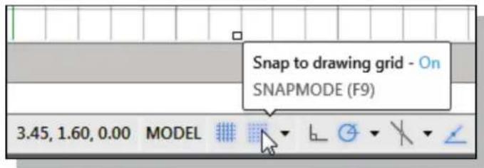
The second button in the Status Bar is the SNAP MODE option and the third button is the GRID DISPLAY option. Note that the buttons in the Status Bar area serve two functions: (1) the status of the specific option, and (2) as toggle switches that can be used to turn these special options ON and OFF. When the corresponding button is highlighted, the specific option is turned ON. Using the buttons is a quick and easy way to make changes to these drawing aid options. The buttons in the Status Bar can also be switched on and off in the middle of another command.

GRID ON
- Left-click the GRID button in the Status Bar to turn ON the GRID DISPLAY option. (Notice in the command prompt area, the message "
" is also displayed.)
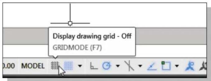
- Move the cursor inside the graphics window, and estimate the distance in between the grid lines by watching the coordinates displayed at the bottom of the screen.

The GRID option creates a pattern of lines that extends over an area on the screen. Using the grid is similar to placing a sheet of grid paper under a drawing. The grid helps you align objects and visualize the distance between them. The grid is not displayed in the plotted drawing. The default grid spacing, which means the distance in between two lines on the screen, is 0.5 inches. We can see that the sketched horizontal line in the sketch is about 4 inches long.

natural_image
Simple geometric star shape drawn on grid paper with a vertical green line (no text or symbols)SNAP MODE ON
- Left-click the SNAP MODE button in the Status Bar to turn ON the SNAP option.

- Move the cursor inside the graphics window, and move the cursor diagonally on the screen. Observe the movement of the cursor and watch the coordinates display at the bottom of the screen.
The SNAP option controls an invisible rectangular grid that restricts cursor movement to specified intervals. When SNAP mode is on, the screen cursor and all input coordinates are snapped to the nearest point on the grid. The default snap interval is 0.5 inches and aligned to the grid points on the screen.

-
Click on the Line icon in the Draw toolbar. In the command prompt area, the message “_line Specify first point:” is displayed.
-
On your own, create another sketch of the five-point star with the GRID and SNAP options switched ON.


natural_image
Two identical five-pointed star drawn on a grid background, no text or symbols present.- Use the right-mouse-button and select Enter in the popup menu to end the Line command if you have not done so.
Using the ERASE Command
One of the advantages of using a CAD system is the ability to remove entities without leaving any marks. We will erase two of the lines using the Erase command.

-
Pick Erase in the Modify toolbar. (The icon is a picture of an eraser at the end of a pencil.) The message "Select objects" is displayed in the command prompt area and AutoCAD awaits us to select the objects to erase.
-
Left-click the SNAP MODE button on the Status Bar to turn OFF the SNAP MODE option so that we can more easily move the cursor on top of objects. We can toggle the Status Bar options ON or OFF in the middle of another command.
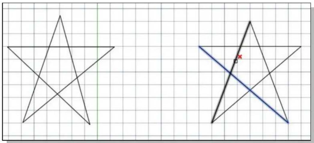
- Select any two lines on the screen; the selected lines are highlighted as shown in the figure below.
To deselect an object from the selection set, hold down the [SHIFT] key and select the object again.
- Right-mouse-click once to accept the selections. The selected two lines are erased.
Repeat the Last Command

- Inside the graphics window, click once with the right-mouse-button to bring up the popup option menu.
- Pick Repeat Erase, with the left-mouse-button, in the popup menu to repeat the last command. Notice the other options available in the popup menu.
AutoCAD 2016 offers many options to accomplish the same task. Throughout this text, we will emphasize the use of the AutoCAD Heads-up Design™ interface, which means we focus on the screen, not on the keyboard.
- Move the cursor to a location that is above and toward the left side of the entities on the screen. Left-mouse-click once to start a corner of a rubber-band window.
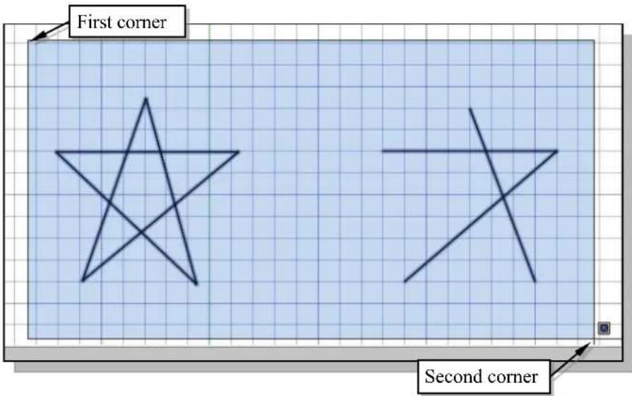
- Move the cursor toward the right and below the entities, and then left-mouse-click to enclose all the entities inside the selection window. Notice all entities that are inside the window are selected. (Note the enclosed window selection direction is from top left to bottom right.)
- Inside the graphics window, right-mouse-click once to proceed with erasing the selected entities.
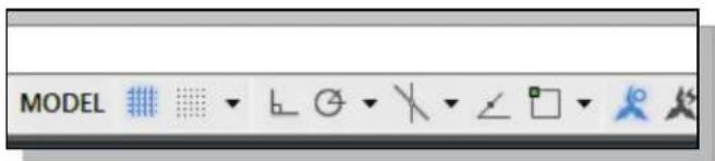
On your own, create a free-hand sketch of your choice using the Line command. Experiment with using the different commands we have discussed so far. Reset the status buttons so that only the GRID DISPLAY option is turned ON as shown.
The CAD Database and the User Coordinate System
natural_image
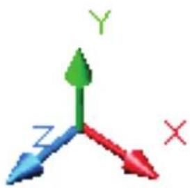
3D coordinate system with X, Y, Z axes (no numerical labels or text annotations)- Designs and drawings created in a CAD system are usually defined and stored using sets of points in what is called world space. In most CAD systems, the world space is defined using a three-dimensional Cartesian coordinate system. Three mutually perpendicular axes, usually referred to as the X-, Y-, and Z-axes, define this system. The intersection of the three coordinate axes forms a point called the origin. Any point in world space can then be defined as the distance from the origin in the X-, Y- and Z-directions. In most CAD systems, the directions of the arrows shown on the axes identify the positive sides of the coordinates.
A CAD file, which is the electronic version of the design, contains data that describes the entities created in the CAD system. Information such as the coordinate values in world space for all endpoints, center points, etc. along with the descriptions of the types of entities are all stored in the file. Knowing that AutoCAD stores designs by keeping coordinate data helps us understand the inputs required to create entities.

The icon near the bottom left corner of the default AutoCAD graphics window shows the positive X-direction and positive Y-direction of the coordinate system that is active. In AutoCAD, the coordinate system that is used to create entities is called the user coordinate system (UCS). By default, the user coordinate system is aligned to the world coordinate system (WCS). The world coordinate system is a coordinate system used by AutoCAD as the basis for defining all objects and other coordinate systems defined by the users. We can think of the origin of the world coordinate system as a fixed point being used as a reference for all measurements. The default orientation of the Z-axis can be considered as positive values in front of the monitor and negative values inside the monitor.
Changing to the 2D UCS Icon Display
In AutoCAD 2016, the UCS icon is displayed in various ways to help us visualize the orientation of the drawing plane.

2D UCS at WCS

2D UCS broken
penci

right side view of 2D UCS

3D UCS at WCS
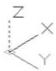
3D UCS viewed from below
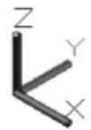
Shaded UCS icon
- Click on the View pull-down menu and select
[Display] → [UCS Icon] → [Properties...]
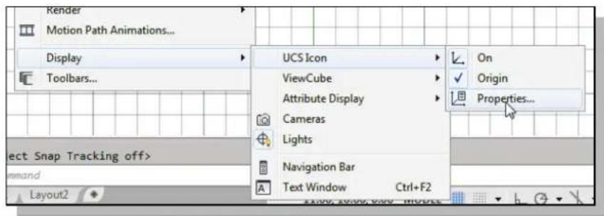

- In the UCS icon style section, switch to the 2D option as shown.
- Click OK to accept the settings.
Note the W symbol in the UCS icon indicates that the UCS is aligned to the world coordinate system.
Cartesian and Polar Coordinate Systems
In a two-dimensional space, a point can be represented using different coordinate systems. The point can be located, using a Cartesian coordinate system, as X and Y units away from the origin. The same point can also be located using the polar coordinate system, as r and units away from the origin.
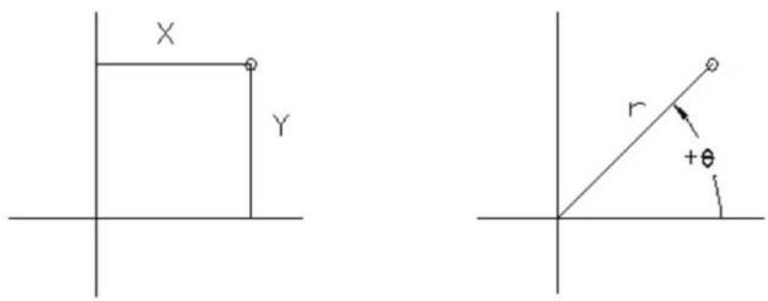
For planar geometry, the polar coordinate system is very useful for certain applications. In the polar coordinate system, points are defined in terms of a radial distance, r, from the origin and an angle between the direction of r and the positive X axis. The default system for measuring angles in AutoCAD 2016 defines positive angular values as counter-clockwise from the positive X-axis.
Absolute and Relative Coordinates
- AutoCAD 2016 also allows us to use absolute and relative coordinates to quickly construct objects. Absolute coordinate values are measured from the current coordinate system's origin point. Relative coordinate values are specified in relation to previous coordinates.
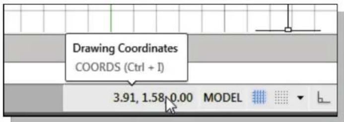
Note that the coordinate display area can also be used as a toggle switch; each left-mouse-click will toggle the coordinate display on or off.
In AutoCAD 2016, the absolute coordinates and the relative coordinates can be used in conjunction with the Cartesian and polar coordinate systems. By default, AutoCAD expects us to enter values in absolute Cartesian coordinates, distances measured from the current coordinate system's origin point. We can switch to using the relative coordinates by using the @ symbol. The @ symbol is used as the relative coordinates specifier, which means that we can specify the position of a point in relation to the previous point.
Defining Positions
In AutoCAD, there are five methods for specifying the locations of points when we create planar geometric entities.
➢ Interactive method: Use the cursor to select on the screen.
Absolute coordinates (Format: X,Y): Type the X and Y coordinates to locate the point on the current coordinate system relative to the origin.
➢ Relative rectangular coordinates (Format: @X,Y): Type the X and Y coordinates relative to the last point.
➢ Relative polar coordinates (Format: @Distance<angle): Type a distance and angle relative to the last point.
Direct Distance entry technique: Specify a second point by first moving the cursor to indicate direction and then entering a distance.
GRID Style Setup

- In the Status Bar area, right-mouse-click on SnapMode and choose [Snap settings].
-
In the Drafting Settings dialog box, select the Snap and Grid tab if it is not the page on top.
-
Change Grid Style to Display dotted grid in 2D model Space as shown in the below figure.

- Pick OK to exit the Drafting Settings dialog box.
The GuidePlate
We will next create a mechanical design using the different coordinate entry methods.

The rule for creating CAD designs and drawings is that they should be created at full size using real-world units. The CAD database contains all the definitions of the geometric entities and the design is considered as a virtual, full-sized object. Only when a printer or plotter transfers the CAD design to paper is the design scaled to fit on a sheet. The tedious task of determining a scale factor so that the design will fit on a sheet of paper is taken care of by the CAD system. This allows the designers and CAD operators to concentrate their attention on the more important issues – the design.

-
Select the Line command icon in the Draw toolbar. In the command prompt area, near the bottom of the AutoCAD graphics window, the message “_line Specify first point:” is displayed. AutoCAD expects us to identify the starting location of a straight line.
-
We will locate the starting point of our design at the origin of the world coordinate system.
Command: _line Specify first point: 0,0 (Type 0,0 and press the [ENTER] key once.)
- We will create a horizontal line by entering the absolute coordinates of the second point.
Specify next point or [Undo]: 5.5,0 [ENTER]
![Y W X Specify next point or [Undo]: 5.5,0 LINE Specify next point or [Undo]: Model Layout1 Layout2 7.50, 3.00, 0.00](/content/2026/06/1272807/images/17da53e46a6f616001d3a2319039c8295d7818e6500e0dad1aae20d151fbbfca.jpg)
- Note that the line we created is aligned to the bottom edge of the drawing window. Let us adjust the view of the line by using the Pan Realtime command.
- In the Menu Bar area select: [View] → [Pan] → [Realtime]
![Autodesk AutoCAD 2015 File Edit View Insert Format Tools Draw Dimension Modif Home Insert An Redraw Line Polyline Circle Regen Regen All Zoom Draw Pan Realtime Drawing1* [~][Top][2D Wireframe] SteeringWheels ShowMotion Orbit Camera Walk and Fly Clean Screen Ctrl+0 Viewpoint Left Right Up Down](/content/2026/06/1272807/images/6dec41723f2cbf877688bd0a2e30ee4aaa87ddaea677b43d0b480514df8ddffc.jpg)
The available Pan commands enable us to move the view to a different position. The Pan-Realtime function acts as if you are using a video camera.
-
Move the cursor, which appears as a hand inside the graphics window, near the center of the drawing window, then push down the left-mouse-button and drag the display toward the right and top side until we can see the sketched line. (Notice the scroll bars can also be used to adjust viewing of the display.)
-
Press the [Esc] key to exit the Pan-Realtime command. Notice that AutoCAD goes back to the Line command.
- We will create a vertical line by using the relative rectangular coordinates entry method, relative to the last point we specified:
Specify next point or [Close/Undo]: @0,2.5 [ENTER]
![Resuming LINE command. LINE Specify next point or [Undo]: @0,2.5 Model Layout1 Layout2](/content/2026/06/1272807/images/0dc23aa299f1fb6290b1ba1d43104c39f00a636983615fd05e7da79dfb511fc1.jpg)
- We can mix any of the entry methods in positioning the locations of the endpoints. Move the cursor to the Status Bar area, and turn ON the SNAP MODE option.

Note that the Line command is resumed as the settings are adjusted.

- Left-click once on the coordinates display area to switch to a different coordinate display option. Note the coordinates display area has changed to show the length of the new line and its angle. Each click will change the display format of the cursor coordinates.

- On your own, left-click on the coordinates display area to observe the switching of the coordinate display; set the display back to using the world coordinate system.

-
Create the next line by picking the location, world coordinates (8,2.5), on the screen.
-
We will next use the relative polar coordinates entry method, relative to the last point we specified:
Specify next point or [Close/Undo]: @3<90 [ENTER]
(Distance is 3 inches with an angle of 90 degrees.)

- Using the relative rectangular coordinates entry method to create the next line, we can imagine a reference coordinate system aligned at the previous point. Coordinates are measured along the two reference axes.
Specify next point or [Close/Undo]:
@-1.5,1 [ENTER]
(-1.5 and 1 inches are measured relative to the reference point.)
- Move the cursor directly to the left of the last point and use the direct distance entry technique by entering 6.5 [ENTER].
![Specify next point or [Close/Undo]: @-1.5,1 LINE Specify next point or [Close Undo]: 6.5 Model Layout1 Layout2](/content/2026/06/1272807/images/3bb65c2c0b0a35ade1900905c8bb5640352b55d34875303cd40b825af5e2271d.jpg)

-
For the last segment of the sketch, we can use the Close option to connect back to the starting point. Inside the graphics window, right-mouse-click and a popup menu appears on the screen.
-
Select Close with the left-mouse-button to connect back to the starting point and end the Line command.

natural_image
Simple geometric shape outline on a grid background, no text or symbols presentCreating Circles
- The menus and toolbars in AutoCAD 2016 are designed to allow the CAD operator to quickly activate the desired commands.

-
In the Draw toolbar, click on the little triangle below the circle icon. Note that the little triangle indicates additional options are available.
-
In the option list, select: [Center, Diameter]
![Autodesk AutoCAD 2016 File Edit View Insert Format Tools Draw Dimension Home Insert Annotate Parametric View Manage Output Add-ins Line Polyline Circle Arc Center, Radius Center, Diameter 2-Point 3-Point Tan, Tan Tan, Tan, Tan Start I-[]Top]2D Wire Modify Annotation Center, Diameter Creates a circle using a center point and a diameter CIRCLE Press F1 for more help](/content/2026/06/1272807/images/cd19b1b4bb5c313b08b85e97aa3730013652c2d1ec3e93f9dafd67911b6938f8.jpg)
Notice the different options available under the circle submenu:
• Center, Radius: Draws a circle based on a center point and a radius.
• Center, Diameter: Draws a circle based on a center point and a diameter.
• 2 Points: Draws a circle based on two endpoints of the diameter.
• 3 Points: Draws a circle based on three points on the circumference.
- TTR-Tangent, Tangent, Radius: Draws a circle with a specified radius tangent to two objects.
- TTT-Tangent, Tangent, Tangent: Draws a circle tangent to three objects.
- In the command prompt area, the message "Specify center point for circle or [3P/2P/Ttr (tan tan radius)]:" is displayed. AutoCAD expects us to identify the location of a point or enter an option. We can use any of the four coordinate entry methods to identify the desired location. We will enter the world coordinates (2.5,3) as the center point for the first circle.
Specify center point for circle or [3P/2P/Ttr (tan tan radius)]: 2.5,3 [ENTER]
![Command: _circle ✓ CIRCLE Specify center point for circle or [3P 2P Ttr (tan tan radius)]: 2.5,3| Model Layout1 Layout2 10.50, 4.50, 0.00 MODEL](/content/2026/06/1272807/images/24c7efece10d06f679714ce459a6f4681bf6dbf658930116917fc4c8abc297eb.jpg)
- In the command prompt area, the message "Specify diameter of circle:" is displayed.
Specify diameter of circle: 2.5 [ENTER]

natural_image
Pure geometric diagram with a circle and X/Y/Z axis labels on a dotted grid background (no text or symbols beyond axis markers)
- Inside the graphics window, right-mouse-click to bring up the popup option menu.
- Pick Repeat CIRCLE with the left-mouse-button in the popup menu to repeat the last command.
- Using the relative rectangular coordinates entry method, relative to the center-point coordinates of the first circle, we specify the location as (2.5,2) .
Specify center point for circle or [3P/2P/Ttr (tan tan radius)]: @2.5,2 [ENTER]
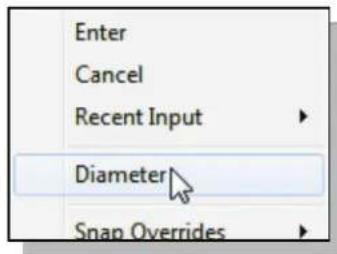
- In the command prompt area, the message "Specify Radius of circle: <2.50>" is displayed. The default option for the Circle command in AutoCAD is to specify the radius and the last radius used is also displayed in brackets.
-
Inside the graphics window, right-mouse-click to bring up the popup option menu and select Diameter as shown.
-
In the command prompt area, enter 1.5 as the diameter.
Specify Diameter of circle<2.50>: 1.5 [ENTER]
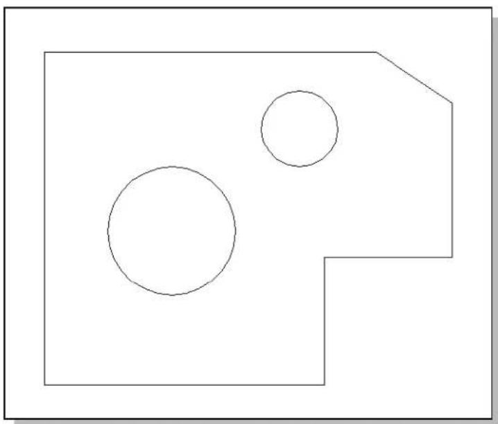
natural_image
Simple geometric diagram with two circles inside a polygonal shape (no text or symbols)Saving the CAD Design

- In the Application Menu, select:
[Application] → [Save]
Note the command can also be activated with the quick-key combination of [Ctrl]+[S] .
- In the Save Drawing As dialog box, select the folder in which you want to store the CAD file and enter GuidePlate in the File name box.

- Click Save in the Save Drawing As dialog box to accept the selections and save the file. Note the default file type is DWG, which is the standard AutoCAD drawing format.
Close the Current Drawing
Several options are available to close the current drawing:

Select [Close] → [Current Drawing] in the Application Menu Bar as shown.
Enter Close at the command prompt.
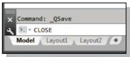
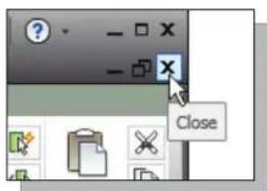
The third option is to click on the [Close] icon located at the upper-right-hand corner of the drawing window.
The Spacer Design
- We will next create the spacer design using more of AutoCAD's drawing tools.

Start a New Drawing
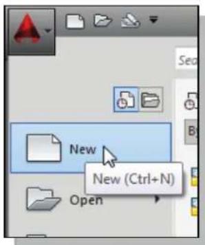
-
In the Application Menu, select [New] to start a new drawing.
-
The Select Template dialog box appears on the screen. Click Open to accept the default acad.dwt as the template to open.
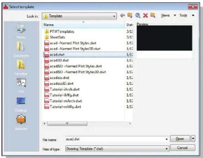
The dwt file type is the AutoCAD template file format. An AutoCAD template file contains predefined settings to reduce the amount of tedious repetitions.
Drawing Units Setup
Every object we construct in a CAD system is measured in units. We should determine the system of units within the CAD system before creating the first geometric entities.

- Click on the Length Type option to display the different types of length units available. Confirm the Length Type is set to Decimal.

- In the Menu Bar select:
[Format] → [Units]
- The AutoCAD Menu Bar contains multiple pull-down menus where all of the AutoCAD commands can be accessed. Note that many of the menu items listed in the pull-down menus can also be accessed through the Quick Access toolbar and/or Ribbon panels.
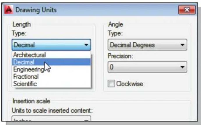
-
On your own, examine the other settings that are available.
-
In the Drawing Units dialog box, set the Length Type to Decimal. This will set the measurement to the default English units, inches.
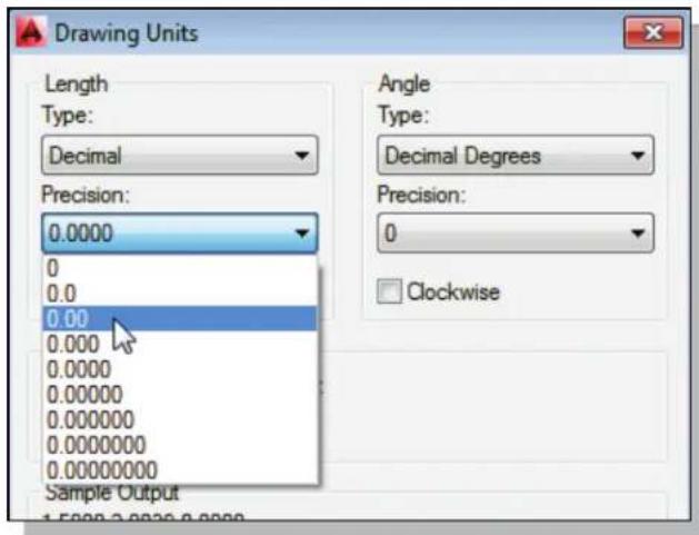
- Set the Precision to two digits after the decimal point as shown in the above figure.
- Pick OK to exit the Drawing Units dialog box.
![AUTODESK AutoCAD 2016 - [Format] → [Units] - 3](/content/2026/06/1272807/images/9597edf1098ab6947acd58bb31c22195a0eff55c7ff7e3af59189e569ce798c6.jpg)
Drawing Area Setup
✿ Next, we will set up the Drawing Limits by entering a command in the command prompt area. Setting the Drawing Limits controls the extents of the display of the grid. It also serves as a visual reference that marks the working area. It can also be used to prevent construction outside the grid limits and as a plot option that defines an area to be plotted/printed. Note that this setting does not limit the region for geometry construction.

- In the Menu Bar select: [Format] [Drawing Limits]
- In the command prompt area, the message "Reset Model Space Limits: Specify lower left corner or [On/Off] <0.00,0.00>:" is displayed. Press the ENTER key once to accept the default coordinates <0.00,0.00>.
![Command: '_limits Reset Model space limits: LIMITS Specify lower left corner or [ON OFF] <0.0000,0.0000>: Model Layout1 Layout2 7.2181, 7.0502,](/content/2026/06/1272807/images/05a5f6734d731a0d18f58b2b6091dc6f172f0ac8ac0597d61f597f1adb25db88.jpg)
- In the command prompt area, the message "Specify upper right corner <12.00,9.00>:" is displayed. Press the ENTER key again to accept the default coordinates <12.00,9.00>.
![Reset Model space limits: Specify lower left corner or [ON/OFF] <0.0000,0.0000>: LIMITS Specify upper right corner <12.0000,9.0000>: Model Layout1 Layout2 0.0012,3.9069,](/content/2026/06/1272807/images/87746368650bffd3f944ee9ce66fb76011e311e7849087b2d38aa2070f148a59.jpg)
- On your own, move the graphics cursor near the upper-right corner inside the drawing area and note that the drawing area is unchanged. (The Drawing Limits command is used to set the drawing area, but the display will not be adjusted until a display command is used.)
![Autodesk AutoCAD 2015 Drawing: File Edit View Insert Format Tools Draw Dimension Modify Home Insert An Redraw Regen Regen All Line Polyline Circle Zoom Pan SteeringWheels ShowMotion Orbit Camera Walk and Fly Clean Screen Ctrl+0 Viewports Named Views... 3D Views Create Camera New Tab [-][Top]2D Wireframe Realtime Previous Window Dynamic Scale Center Object In Out All Excents](/content/2026/06/1272807/images/d7e05db67c70b2f5af563447920eb1350268fb35b29db95531b7eba6aea99d53.jpg)
- Inside the Menu Bar area select:
$$ [ \text { View } ] \rightarrow [ \text { Zoom } ] \rightarrow [ \text { All } ] $$
The Zoom All command will adjust the display so that all objects in the drawing are displayed to be as large as possible. If no objects are constructed, the Drawing Limits are used to adjust the current viewport.
- Move the graphics cursor near the upper-right corner inside the drawing area, and note that the display area is updated.

-
In the Status Bar area, right-mouse-click on SnapMode and choose [Snap Settings].
-
In the Drafting Settings dialog box, switch on the Snap and Grid options as shown.
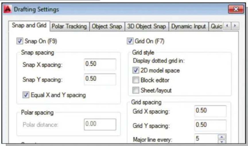
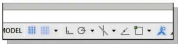
On your own, exit the Drafting Settings dialog box and reset the status buttons so that only GRID DISPLAY and SNAP MODE are turned ON as shown.
Using the Line Command
- We will create a horizontal line by using the relative rectangular coordinates entry method, relative to the last point we specified:
@6,0 [ENTER]
![Specify first point: LINE Specify next point or [Undo]; Model Layout1 Layout2](/content/2026/06/1272807/images/17ffefc8a5f64c2b5fed6f4a6b0df0957fea7b774818ead6fcdccd8b3870bb6d.jpg)
-
Next, we will use the direct input method. First, move the cursor directly to the left of the last endpoint of the line segments.
-
Select the Line command icon in the Draw toolbar. In the command prompt area, near the bottom of the AutoCAD graphics window, the message “_line Specify first point:” is displayed. AutoCAD expects us to identify the starting location of a straight line.
-
To further illustrate the usage of the different input methods and tools available in AutoCAD, we will start the line segments at an arbitrary location. Start at a location that is somewhere in the lower left side of the graphics window.
![Specify first point: LINE Specify next point or [Unid0]; Model Layout1 Layout2 6.50](/content/2026/06/1272807/images/a5de91b0ad60cdcc8fd0098e984591ad6a21c62fcbe332369aeaf358ba58f14b.jpg)
- Next, create a vertical line by using the relative polar coordinates entry method, relative to the last point we specified:
@3<90 [ENTER]
![Specify first point: √ LINE Specify next point or [Undo]: Model Layout1 Layout2](/content/2026/06/1272807/images/eece3bdf23e5668faec8378d73ccd04ca3fcc4d88e75d3c1538a67ccc40d3f68.jpg)
![Specify next point or [Undo]: LINE Specify next point or [Undo]: 2 Model Layout1 Layout2](/content/2026/06/1272807/images/31dcd41d66d8771dc653fe39c8e1502316f2cc66f78e752c09fdb0a866ccf57c.jpg)
- Use the direct distance entry technique by entering 2 [ENTER].

- On your own, repeat the above steps and create the four additional line segments, using the dimensions as shown.
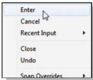
- To end the line command, we can either hit the [Enter] key on the keyboard or use the Enter option, right-mouse-click and a popup menu appears on the screen.
- Select Enter with the left-mouse-button to end the Line command.
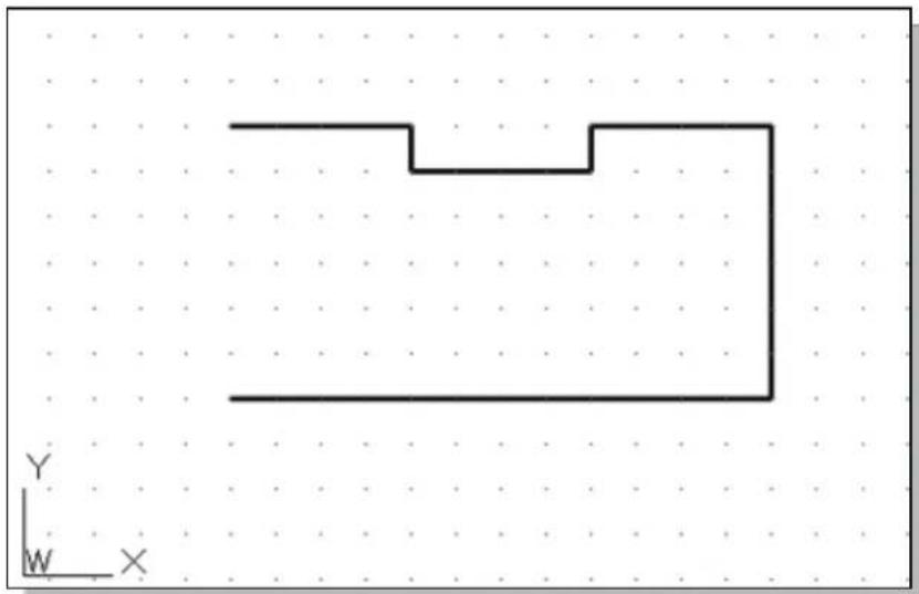
natural_image
Pure geometric shape outline on a grid background with X and Y axis indicators (no text or symbols)Using the ERASE Command
The vertical line on the right was created as a construction line to aid the construction of the rest of the lines for the design. We will use the Erase command to remove it.

- Pick Erase in the Modify toolbar. The message "Select objects" is displayed in the command prompt area and AutoCAD awaits us to select the objects to erase.

natural_image
Pure electrical circuit lines without any symbols-
Select the vertical line as shown.
-
Click once with the right-mouse-button to accept the selection and delete the line.
Using the Arc Command

- Click the down-arrow icon of the Arc command in the Draw toolbar to display the different Arc construction options.
AutoCAD provides eleven different ways to create arcs. Note that the different options are used based on the geometry conditions of the design. The more commonly used options are the 3-Points option and the Center-Start-End option. - Select the Center-Start-End option as shown. This option requires the selection of the center point, start point and end point location, in that order, of the arc.

natural_image
Pure electrical circuit lines without any symbols-
Move the cursor to the middle of the two horizontal lines and align the cursor to the two endpoints as shown. Click once with the right-mouse-button to select the location as the center point of the new arc.
-
Move the cursor downward and select the right endpoint of the bottom horizontal line as the start point of the arc.

natural_image
Two horizontal signal waveforms on a grid background, no text or symbols present
natural_image
Pure electrical circuit lines without any symbols-
Move the cursor to the right endpoint of the top horizontal line as shown. Pick this point as the endpoint of the new arc.
-
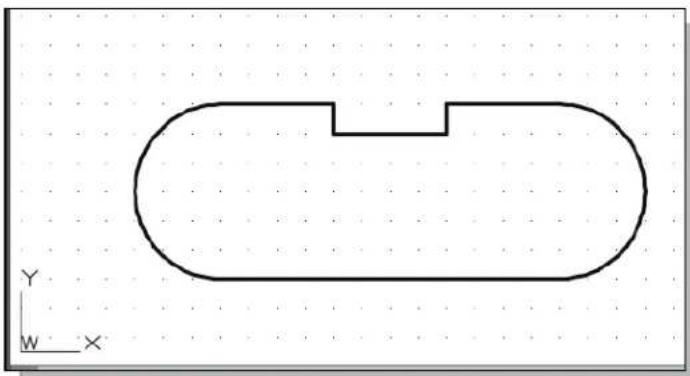
On your own, repeat the above steps and create the other arc as shown. Note that in most CAD packages, positive angles are defined as going counterclockwise; therefore, the starting point of the second arc should be at the endpoint on top.
natural_image
Pure geometric shape outline on a grid background with X, Y, W axis indicators (no text or symbols)Using the Circle Command

- Select the [Circle] → [Center, Diameter] option as shown.
![Specify center point for circle or [3P/2P/Ttr (tan tan radius)]: - CIRCLE Specify radius of circle or [Diameter]: _d Specify diameter of circle: 1.25](/content/2026/06/1272807/images/0bd9f43c81732d9f576a97cca8e1b59bfaaa6ae79eb8483778eb468fc03fe446.jpg)
-
Select the same location for the arc center as the center point for the new circle.
-
In the command prompt area, the message "Specify diameter of circle:" is displayed. Specify diameter of circle: 1.25 [ENTER]
-
On your own, create the other circle and complete the drawing as shown.
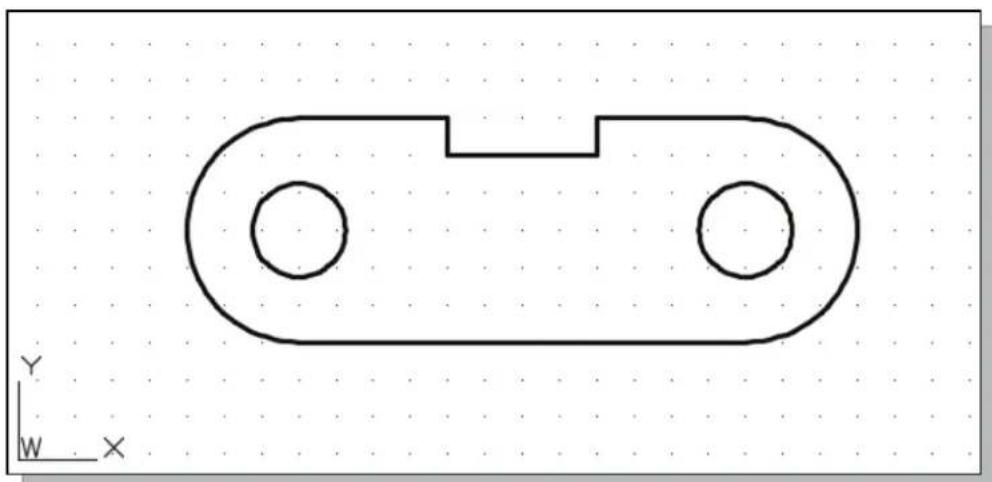
natural_image
Pure technical drawing of a mechanical part with two circular holes, no text or symbols presentSaving the CAD Design
- In the Quick Access Toolbar, select: [Save]

Note the command can also be activated with the quick-key combination of [Ctrl]+[S] .
2. In the Save Drawing As dialog box, select the folder in which you want to store the CAD file and enter Spacer in the File name box.

- Click Save in the Save Drawing As dialog box to accept the selections and save the file. Note the default file type is DWG, which is the standard AutoCAD drawing format.
Exit AutoCAD 2016
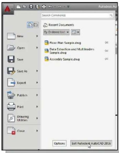
To exit AutoCAD 2016, select Exit AutoCAD in the Menu Bar or type QUIT at the command prompt. Note the command can also be activated with the quick-key combination of [Ctrl]+[Q].
Review Questions: (Time: 20 minutes)
-
What are the advantages and disadvantages of using CAD systems to create engineering drawings?
-
What is the default AutoCAD filename extension?
-
How do the GRID and SNAP options assist us in sketching?
-
List and describe the different coordinate entry methods available in AutoCAD.
-
When using the Line command, which option allows us to quickly create a line-segment connecting back to the starting point?
-
List and describe the two types of coordinate systems commonly used for planar geometry.
-
Which key do you use to quickly cancel a command?
-
When you use the Pan command, do the coordinates of objects get changed?
-
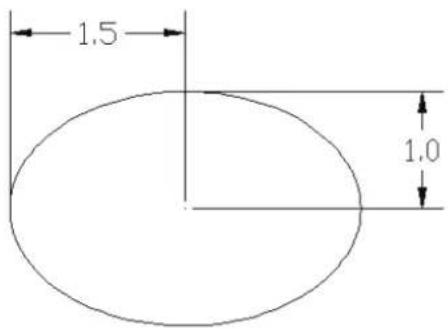
Find information on how to draw ellipses in AutoCAD through the Autodesk Exchange, and create the following arc. If it is desired to position the center of the ellipse to a specific location, which ellipse command is more suitable?
- Find information on how to draw arcs in AutoCAD through the Autodesk Exchange and create the following arc. List and describe two methods to create arcs in AutoCAD.

Exercises:
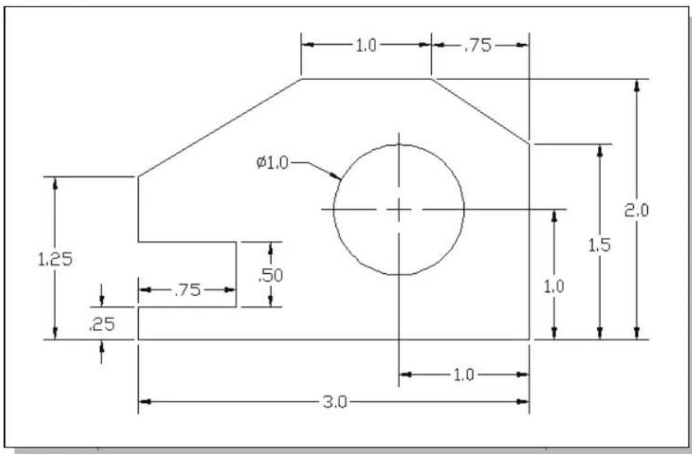
(All dimensions are in inches.) (Time: 60 minutes)
1. Angle Spacer
2. Base Plate

- T-Clip

- Channel Plate

5. Slider Block (Create the Front sketch of the design.)
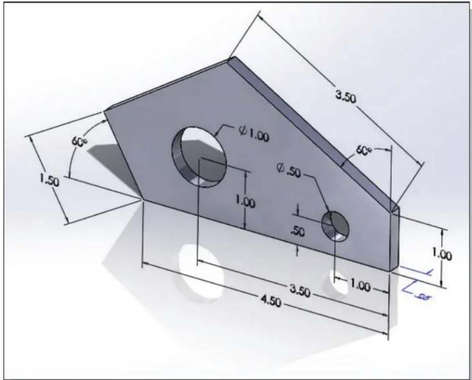
6. Circular Spacer



- AutoCAD® 2016 Tutorial First Level 2D Fundamentals
- Chapter 1 AutoCAD Fundamentals
- Learning Objectives
- AutoCAD Certified User Examination Objectives Coverage
- Section 1: Controlling the Display in Drawings
- Section 2: Creating Basic Drawings
- Section 3: Manipulating Objects
- Introduction
- Starting Up AutoCAD 2016
- Drawing Units Setup
- [Format] → [Units]
- Drawing Area Setup
- [Format] → [Drawing Limits]
- Drawing Lines with the LINE Command
- Visual Reference
- GRID ON
- SNAP MODE ON
- Using the ERASE Command
- Repeat the Last Command
- The CAD Database and the User Coordinate System
- Changing to the 2D UCS Icon Display
- Cartesian and Polar Coordinate Systems
- Absolute and Relative Coordinates
- Defining Positions
- GRID Style Setup
- The GuidePlate
- Creating Circles
- Saving the CAD Design
- [Application] → [Save]
- Close the Current Drawing
- The Spacer Design
- Start a New Drawing
- Using the Line Command
- Using the Arc Command
- Using the Circle Command
- Exit AutoCAD 2016
- Review Questions: (Time: 20 minutes)
- Exercises:
- Angle Spacer
- Base Plate
- Slider Block (Create the Front sketch of the design.)
- Circular Spacer
Brand : AUTODESK
Model : AutoCAD 2016
Category : Software