
6650-LC - Pliers 3M - Free user manual and instructions
Find the device manual for free 6650-LC 3M in PDF.


| Product Type | Pliers |
| Brand | 3M |
| Model | 6650-LC |
| Material | High carbon steel with forged construction |
| Handle Material | Insulated rubberized grips for comfort and safety |
| Overall Length | 8 inches (203 mm) |
| Weight | 0.5 lbs (227 g) |
| Jaw Capacity | 1.5 inches (38 mm) |
| Cutting Capacity | Up to 12 AWG copper wire |
| Primary Functions | Gripping, cutting, bending, and twisting wires |
| Safety Rating | VDE certified for 1000V AC insulated work |
| Maintenance | Clean with a dry cloth; apply light oil to pivot point periodically |
| Storage | Store in a dry place away from moisture |
| Repairability | Replacement parts available through 3M service centers; pivot pin repairable |
| Country of Origin | Manufactured in USA |
Frequently Asked Questions - 6650-LC 3M
User questions about 6650-LC 3M
0 question about this device. Answer the ones you know or ask your own.
Ask a new question about this device
Download the instructions for your Pliers in PDF format for free! Find your manual 6650-LC - 3M and take your electronic device back in hand. On this page are published all the documents necessary for the use of your device. 6650-LC by 3M.
USER MANUAL 6650-LC 3M
Fiber Optic Connectors
Installation
Contents
1.0 Safety and Helpful Hints....3
Hot Melt Oven Safety Information ....3
2.0 3M ™ LC Expansion 6650-LC Kit Contents ....4
3.0 3M ™ LC Connectors ....5
4.0 Setup 6
5.0 900 micron Cable Connector Preparation....8
6.0 1.6 – 2.0 mm Jacketed Cable Connector Preparation ....8
7.0 3.0 mm Jacketed Cable Connector Preparation ....8
8.0 Strip Guide ..... 9
9.0 Stripping Procedure for 900 micron Fiber 9
10.0 Stripping Procedure for 1.6 – 2.0 mm Jacketed Fiber....9
11.0 Stripping Procedure for 3 mm Jacketed Fiber....11
12.0 Connector Mounting 12
13.0 Boot Placement for 900 micron Fiber....14
14.0 Crimping and Boot Placement for 1.6 – 2.0 mm Jacketed Fiber .....14
15.0 Crimping and Boot Placement for 3 mm Jacketed Fiber....16
16.0 Scribing ..... 17
17.0 Multimode Polish....18
18.0 Singlemode Polish to -40db....21
19.0 Singlemode Polish to -55db....23
20.0 Finishing ..... 24
21.0 Installing Duplex Yokes....24
22.0 3M TM Expansion Kit 6650-LC and Replacement Part Numbers .....26
1.0 Safety and Helpful Hints
Use reagent-grade isopropyl alcohol that is 99% pure to clean the fibers and other components. When terminating connectors on any cable containing grease, ensure that all grease is wiped away and the buffer, coating and fiber are thoroughly cleaned with isopropyl alcohol.
Isopropyl alcohol is not shipped with the 3M included.
TM Field Termination Kits; however, a bottle for the alcohol is
Note: Carefully follow safety, health and environmental information given on the container label or the Material Safety Data Sheet for the isopropyl alcohol.

CAUTION
Do not touch any part of the heating block of the Hot Melt oven during operation. It is very HOT.

WARNING
- Safety glasses should be worn when working around optical fibers.
- Do not view fiber ends if they are illuminated with a laser.
- Keep oven clear from flammable material.
- Disconnect power supply when cleaning.
Hot Melt Oven Safety Information
This Hot Melt Connector Oven is intended for melting Hot Melt adhesive in Hot Melt Connectors. It has been designed and tested for use only with the 3M ™ Fiber Optic Connectors System. Other uses of this product may lead to poor performance or an unsafe condition.

WARNING
- Power cord must be grounded and plugged into a grounded outlet.
- Eye hazard. Do not view fiber ends if they are laser illuminated as eye damage may result. Illuminate fiber ends with white light only.
- Wear safety glasses.
- No serviceable parts - return unit to the manufacturer for servicing.
- For indoor use only.
- To avoid possible environmental contamination, dispose of the unit in accordance with applicable governmental regulations.
- Avoid touching hot surfaces.
Explanation of symbols:
⚠ Warning - Refer to accompanying documents.
⚠️ Caution - Risk of electric shock. Refer all servicing to manufacturer.

This is the EU symbol for equipment that is covered under the Waste from Electrical and Electronic Equipment (WEEE) directive per CENELEC Specification 50419, and it indicates that certain products should not be discarded in the trash, but rather should be recycled. This applies to all electronic pluggable and battery powered products.
2.0 3M TM LC Expansion 6650-LC Kit Contents

A. LC Hot Melt Connector Holder (4)
B. LC Polishing Jig Assembly with Weight
B 1 Spare Polishing Jig
C. LC Crimp Tool
D. LC Adapter for View Scope
E. Heat Shrink Fixture
F. Cleaning Pins (3)
G. Laminated Strip Template
H. Polishing Pads 4.5" × 5.5"
I. Lapping Film
a. 9 micron silicon carbide 5" diameter (Slate Gray)
b. One Step 2 micron AO 5" diameter (Blue/Green)
c. 0.5 micron diamond 4.5" × 5.5" (Pale Gray)
d. 0.02 micron Final Polish SiO 2 4.5" × 5.5" (Frosted White)
To complete the termination of the 3M TM Hot Melt LC Connector, both the 3M TM Universal Hot Melt Kit 6365/6361 and the 6650-LC Expansion Kits are required.
Visually inspect all components. If any component is missing or appears damaged, do not install. Call customer service at 1-800-426-8688 for a replacement product.
3.0 3M TM LC Connectors
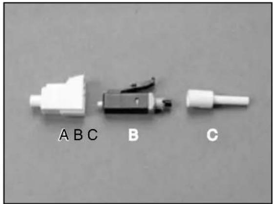
3.1 The Behind The Wall (BTW) LC is used for simplex 900 micron applications. The connector contains (A) dust cap, (B) connector, and (C) strain relief boot.
Note: The BTW LC multimode connector has a beige extender cap at the rear of the connector. The singlemode connector has a blue extender cap at the rear of the connector.
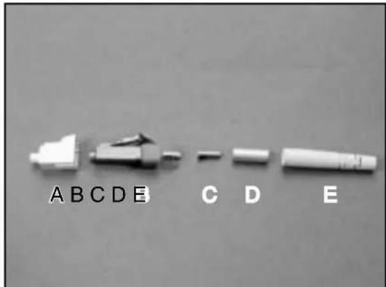
3.1 The duplex 900 micron LC contains (A) dust cap, (B) connector, (C) duplex clip, and (D) strain relief boot.
Note: Do not confuse the multimode or singlemode duplex connectors as they both have black outer housings. Multimode connectors are packaged with beige duplex yokes and singlemode connectors are packaged with blue yokes.

3.2 1.6–2.0 mm LC connector contains a (A) dust cap, (B) connector, (C) heat shrink crimp sleeve, and (D) strain relief boot.

3.3 The 3.0 mm LC connector contains (A) dust cap, (B) connector, (C) metal strength sheath, (D) metal crimp sleeve, (E) strain relief boot.
Note: Multimode simplex yokes are beige and singlemode yokes are blue.
4.0 Setup
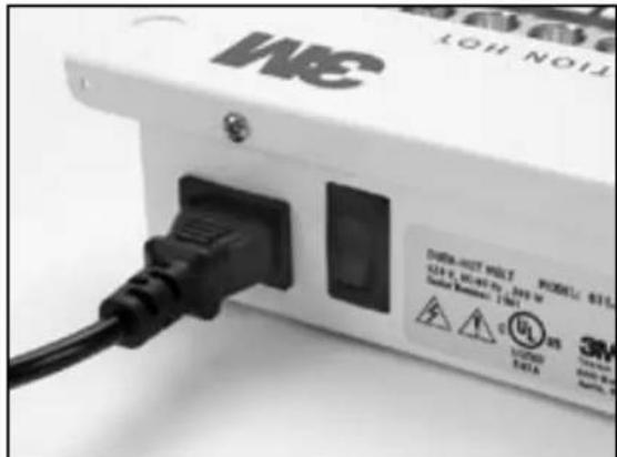
4.1 Plug in the 120V or 230V power cord. Turn on the 3M ™ Hot Melt Oven. The oven requires 6 minutes to warm up (red exposed on switch indicates power on).
4.2 Open the connector package and remove components.
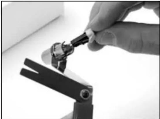
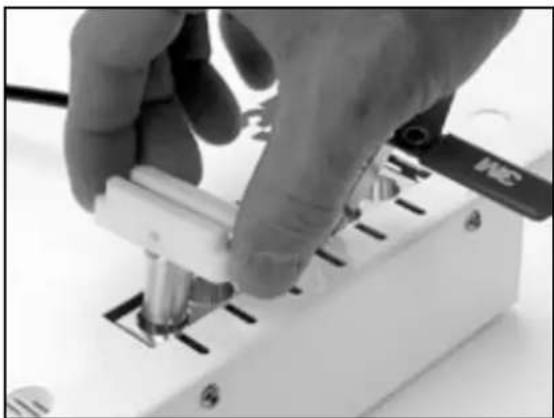
4.3 Attach hot melt holder handle to the load adapter with the slot aligned to the front.

4.4 Insert the connector into the hot melt connector holder.
4.5 Place the load adapter, with slot aligned with handle, into an available port in the oven.
IMPORTANT: Do not place connector in a hot load adapter. This may cause adhesive to flow to the outside of the ferrule. Load adapter should be at room temperature when connector is inserted.
4.6 The 3M TM LC Hot Melt Connector should be in the oven for at least 75 seconds. The connector should not be in the oven longer than 5 minutes.
4.7 Place the heat shrink fixture in an available port in the oven.
Note: This step is only necessary for use with the 1.6–2.0 mm jacketed LC hot melt connector.

5.0 900 micron Cable Connector Preparation
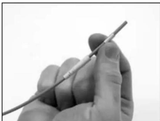
5.1 Place strain relief boot on cable as shown.

6.0 1.6 - 2.0 mm Jacketed Cable Connector Preparation
6.1 Place the strain relief boot first and then the heat shrink crimp sleeve on the cable as shown.

7.0 3.0 mm Jacketed Cable Connector Preparation
7.1 Place the strain relief boot first and then the metal crimp sleeve on the cable as shown.
8.0 Strip Guide
9.0 Stripping Procedure for 900 micron Fiber
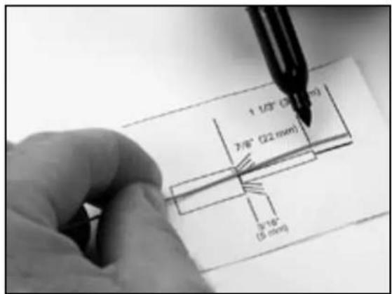
9.1 Place the cable on the strip template. Mark buffer at 11 mm. Using the 3M ™ Stripping Tool 6365-ST, remove the buffer in small increments until 11 mm of buffer has been removed.
9.2 Using a lint-free cloth moistened with isopropyl alcohol, clean the bare fiber to remove any oils or acrylate coating debris.
9.3 Check the final strip length and adjust if necessary.
10.0 Stripping Procedure for 1.6 - 2.0 mm Jacketed Fiber
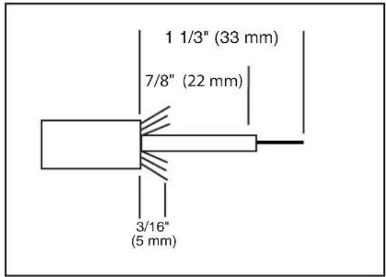
10.1 Place the jacketed fiber on the strip template and use a fiber marking pen to mark the location of the jacket cut. Using the 3M ™ Stripping Tool 6365-ST, remove 33 mm (1 1/3") of jacket off cable.
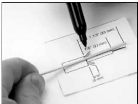
10.2 Snip the aramid yarn to 5-6 mm (approx. 3/16").
10.3 Flare aramid yarn evenly around buffer.
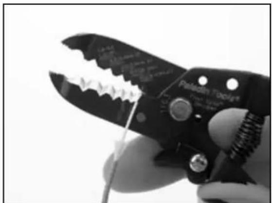
10.4 Using the 3M TM Stripping Tool 6365-ST, remove the buffer in small increments until 21–22 mm (approx. 7/8") of buffer is left.
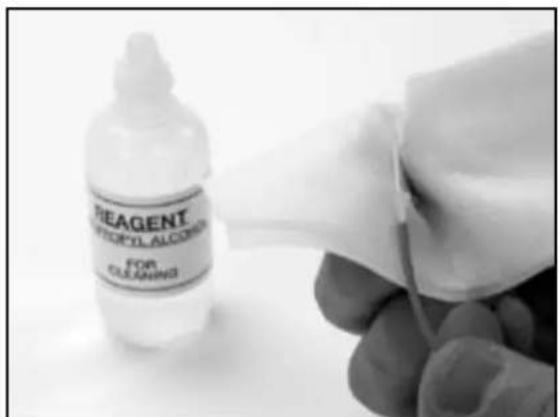
10.5 Using a lint-free cloth moistened with isopropyl alcohol, clean the bare fiber to remove any oils or acrylate coating debris.
10.6 Check the final strip lengths and adjust if necessary


11.0 Stripping Procedure for 3 mm Jacketed Fiber
11.1 Place the jacketed fiber on the strip template and use a fiber marking pen to mark the location of the jacket cut. Using the 3M ™ Stripping Tool 6365-ST, remove 33 mm (1 1/3") of jacket off cable.
11.2 Holding the aramid yarn firmly away from the buffer tube, insert the metal strength sheath over the buffer tube and push down until fully inserted into the jacket. Top of sheath should be even with the upper edge of jacket
11.3 Snip the aramid yarn to 5-6 mm (approximately 3/16").
11.4 Flare aramid yarn evenly around buffer tube.
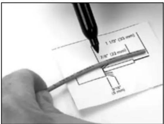


11.5 Using the 3M TM Stripping Tool 6365-ST, remove the buffer in small increments until 21–22 mm (approx. 7/8") of buffer is left.
11.6 Using a lint-free cloth moistened with isopropyl alcohol, clean the bare fiber to remove any oils or acrylate coating debris.
11.7 Check the final strip lengths and adjust if necessary.
12.0 Connector Mounting
12.1 While connector is still in oven, mount fiber into connector inserting until buffer stops inside the connector. Be sure to insert fiber within the guide tube at the rear of the connector.
Note: Removing the connector holder from the oven prior to fiber insertion will cause adhesive to thicken rapidly, greatly limiting the time to insert the fiber.
Cable jackets should be approximately 1mm from the rear of crimp area when buffer is correctly located.
IMPORTANT: Do not lift the connector while in the load adapter during the heating process. This will prevent adhesive from bonding to the load adapter. If adhesive does adhere itself to the inside of the load adapter, use the cleaning pin to remove adhesive prior to inserting next connector. Use alcohol with the pin, if needed.
Note: To ease fiber insertion, make sure fiber is kept very straight when mounting. If resistance is felt when within 1/8" of buffer, you are stubbing and should back out a short distance and re-enter making sure that the fiber is kept straight at all times.


12.2 Maintaining fiber position in connector, push the jacketed fiber into the cable v-slot feature on the load adapter until secure.
12.3 Attempt to line up the holder arm to keep cable as straight as possible.
12.4 Remove the load adapter from the oven by grasping the cool-touch handle.
CAUTION
Do not touch the metal portion of the load adapter or connector, as it will be hot!
12.5 Rest the load adapter in one of the available cooling ports located on both sides of the oven. Let cool for a minimum of 3 minutes.


13.0 Boot Placement for 900 micron Fiber
13.1 Remove connector from the load adapter and slide the boot over connector until fully seated.
IMPORTANT: Remove connector gently so that you don't break the fiber. If connector sticks to the sides of the load adapter when trying to remove, re-heat the connector slightly until connector can be removed from the load adapter. Use the cleaning pin furnished in the kit to scrape the adhesive out of the load adapter hole before proceeding with next connector.
14.0 Crimping and Boot Placement for 1.6 - 2.0 mm Jacketed Fiber
14.1 Slide crimp/shrink tube down and over aramid yarn.
14.2 Remove the connector from the load adapter.

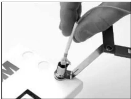

14.3 Using the die labeled "A" with the 3M lettering facing to the left, crimp the metal portion of the sleeve once.
Note: Crimp sleeve must be bottomed against connector prior to crimping. The 3M lettered side of the crimp die should be touching the rear of the connector.
14.4 Place the crimp/shrink tube in the shrink fixture assembly and heat for 8 to 10 seconds. Tube should shrink snug around the jacket. Rotate, if needed, to complete shrink.
14.5 Slide boot over crimp/shrink tube.
Note: Jacketed boots appear the same in the photos but the boots for all 3 types of connectors are different sizes and can not be interchanged.


15.0 Crimping and Boot Placement for 3 mm Jacketed Fiber
15.1 Remove connector from load adapter
15.2 Slide metal crimp sleeve down and over aramid yarn. It should rest over the metal strength sheath as shown.
15.3 Using the LC die labeled "A" with the 3M lettering facing left, crimp the left half of the the crimp ring once making sure that the 3M lettered side of the die is flush with the connector prior to crimping.
Note: The crimp ring must be flush against the connector prior to crimping. The 3M-lettered side of the crimp die should be touching the rear of the connector.
15.4 Using the LC die labeled "B" line up the non-lettered side of the die with the rear of the crimp die and crimp the right half of the crimp ring.
The completed 3 mm crimp shold look like this:
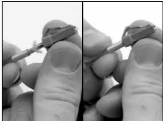


15.5 Slide boot over crimp until boot is flush against the connector.
Note: Jacketed boots appear the same in the photos but the boots for all 3 types of connectors are different sizes and cannot be interchanged.

16.0 Scribing
16.1 Position the scribe blade so the flat side of the blade is resting on the bead of adhesive and the blade is perpendicular to the fiber.
16.2 Score the fiber by gently sliding the blade across the fiber just above the bead of adhesive. Scoring means that you are making a small scratch on the outside of the fiber.
IMPORTANT: The fiber should not break during this step.

16.3 Pull the fiber straight away from the connector. Pull along the axis of the fiber, not to one side or the other. If the fiber does not pull away, score the fiber again.
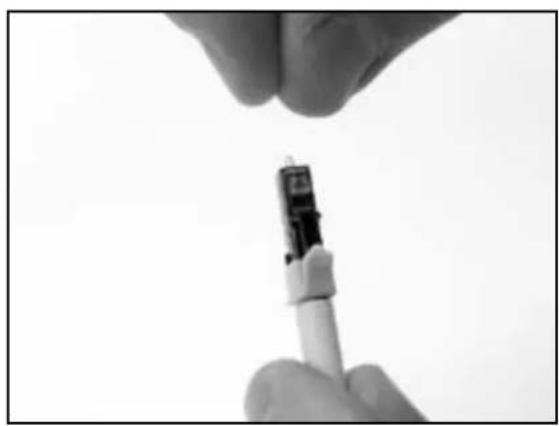
16.4 Dispose of the scrap fiber in the designated container.
17.0 Multimode Polish
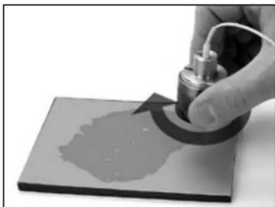
17.1 Perform an air polish by holding the 9 micron lapping film firmly in one hand and gently moving the film in a circular motion for approximately 10 strokes or until approximately one half of the bead height is removed.
Note: You can polish approximately 20 connectors with each piece of 9 micron lapping film.
17.2 Using a lint-free cloth and isopropyl alcohol clean the connector after the air polish to remove all debris left by the 9 micron lapping film.
17.3 Clean the round polishing pad found in the 3M TM Universal Hot Melt Kit 6365/6361 with a lint-free cloth moistened with isopropyl alcohol.
17.4 Place several drops of alcohol onto the round polishing pad.
17.5 Before alcohol evaporates, place a sheet of the pale green 2 micron lapping film, shiny side down on the pad. The alcohol creates suction on the lapping film and helps hold it in place.
17.6 Clean the lapping film with a lint-free cloth moistened with isopropyl alcohol.
Note : The 2 micron lapping film can be used for up to 4 connectors.
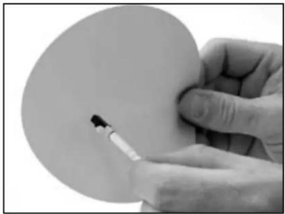
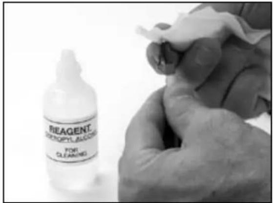
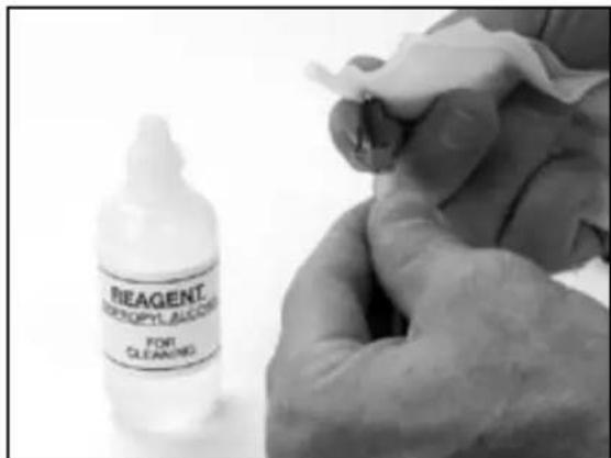
17.7 Clean the flat side of the polishing jig with a lint-free cloth moistened with isopropyl alcohol.
17.8 Place the polishing jig assembly on the lapping film.
17.9 Place the ferrule in the polishing jig aligning the latch side of the connector with the slot until it stops.
Note: The ferrule must be able to slide freely inside the hole in the polishing jig. If not, the ferrule may have adhesive on it which needs to be cleaned off with alcohol and a lint-free cloth.
17.10 Insert the polishing weight into the adapter/jig assembly covering the connector.
Note: The weight should pop up slightly (1/16") when holding the jig flat against the lapping film, indicating that the ferrule can move freely.
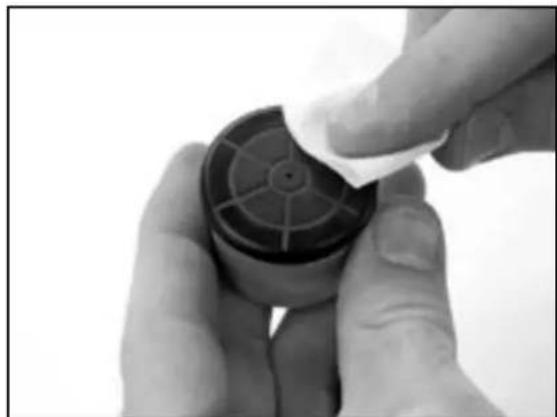


17.11 Polish 10 figure-eight strokes or until bead of adhesive is no longer visible.
Note: Do not hold polishing jig assembly by the weight when polishing. Hold only by the textured polishing adapter.
Note: Because bead is 3 to 4 times smaller than classic hot melt connectors you will not feel the bead of adhesive being removed as you polish.
IMPORTANT: Make sure that polishing jig stays flat on lapping film at all times
17.12 After bead of adhesive is no longer visible, polish an additional 5 strokes.
17.13 Remove the connector from the polishing jig assembly and clean the connector endface with a lint-free cloth moistened with isopropyl alcohol.
17.14 Inspect the connector endface with the 200X Westover ™ Scientific fiber view scope. Use the thumb toggle switch to activate the light onto the fiber end face. There are two light settings—coaxial and oblique angle lighting.


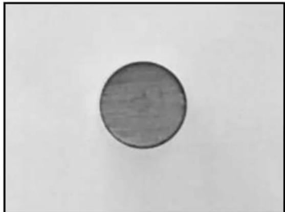
17.15 Good Polish (Coaxial light)
17.16 Good Polish (Oblique light)
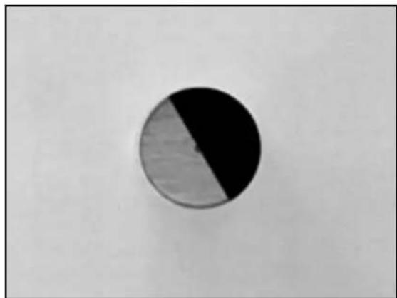
17.17 Bad Polish – Cut or scratch going through center of core. In this picture half of fiber is missing.
18.0 Singlemode Polish to -40db
18.1 Complete steps17.0 through 17.13 of the multimode polish before proceeding further with the singlemode polish.
Note: You may also use steps 18.0 - 18.11 to obtain a cleaner cosmetic multimode polish.
18.2 Clean the gray rectangular polishing pad with a lint-free cloth moistened with isopropyl alcohol.
IMPORTANT: Do not use the black 4.5" x 5.5" pads for the singlemode LC polish. Use only the pale gray pads provided in the 3M™ LC Hot Melt Expansion kit.

18.3 Place several drops of alcohol on to the rectangular rubber pad.
18.4 Before the alcohol evaporates, place a sheet of the 0.5 micron pale gray diamond lapping film on the polishing pad, shiny side down.
18.5 Clean the lapping film with a lint-free cloth moistened with isopropyl alcohol.
Note: The 0.5 micron diamond lapping film can be used for up to 10 connectors.
18.6 Place several drops of distilled water on to the diamond lapping film.
18.7 Insert the connector into the polishing jig assembly.
18.8 Clean the flat side of the polishing jig with a lint-free cloth moistened with isopropyl alcohol.
18.9 Place the polishing jig assembly on the wet diamond lapping film. Perform 3 to 4 figure eights.
18.10 Leaving the polishing jig assembly positioned on the lapping film, rotate 180 degrees. Perform 3 to 4 additional figure eights.


19.0 Singlemode Polish to -55db
Note: Complete steps 17.0 through 17.13 of the multimode polish and 18.0 through 18.11 of the singlemode polish before proceeding further.
19.1 Place several drops of alcohol on to the second gray rectangular rubber pad.
19.2 Before the alcohol evaporates, place a sheet of the white frosted final lapping film on the polishing pad, shiny side down.
19.3 Clean the lapping film with a lint-free cloth moistened with distilled water.
IMPORTANT: Do not clean the white frosted lapping film with alcohol. Use only distilled water.
Note: The frosted final lapping film can be used for up to 5 connectors.
19.4 Place several drops of distilled water onto the frosted lapping film.
19.5 Clean the flat side of the polishing jig with a lint-free cloth moistened with isopropyl alcohol.
19.6 Place the polishing jig assembly on the wet frosted lapping film. Perform 4 figure eights on the wet frosted lapping film.


19.8 Leaving polishing jig assembly positioned on the lapping film rotate 180 degrees. Perform 4 additional figure eights.

19.9 Once polishing is complete, refer to steps 17.14 through 17.17 on inspecting the connector with the 200X fiber view scope before proceeding to final step.
20.0 Finishing
20.1 If connector is not to be immediately put into service, install the protective dust cap.

21.0 Installing Duplex Yokes
21.1 Duplex yokes may be mounted after connector has been terminated.
21.2 With the anti-snag clip facing connector press cable into slot on the duplex yoke and then slide the yoke up and over the boot.
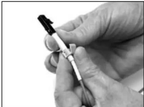
21.3 Taper on the boot will cause the yoke to spread allowing the correct placement at the rear of the connector.
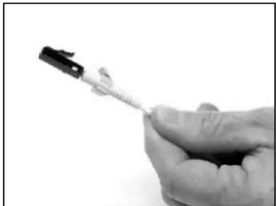
21.4 Pinch the top and bottom of the yoke closed and press together the outer edges of the yoke, snapping firmly into connector.
21.5 A design improvement includes a live hinge on the bottom of the duplex yoke (currently available in multimode). The new duplex yokes will be installed in the same manner as the current yoke, however, the live hinge allows the yoke to be re-opened without damage.

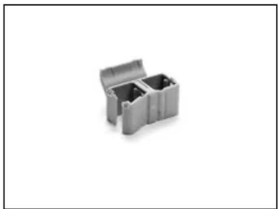
22.0 3M TM Expansion Kit 6650-LC and Replacement Part Numbers
6650-LC LC Expansion Kit (complete) 80-6113-1353-9
6650-LH LC Hot Melt Connector Holder (4 ea.) 80-6113-1348-9
6650-JW LC Polishing Jig Assembly with Weight (includes 2 pucks)....80-6113-1354-7
6650-LT LC Crimp Tool 80-6113-1356-2
6650-VS LC Adapter for View Scope 80-6113-1357-0
6650-HS LC Heat Shrink Fixture....80-6113-1358-8
6650-HC LC Holder Cleaning Pins (3 ea.) 80-6113-1359-6
6650-LP LC Polishing Pad 4.5 X 5.5" (2 ea.)....80-6113-1471-9
6650-LS LC Lapping Film Singlemode Consumable Kit (polishes 400 SM connectors)....80-6113-1472-7
6650-LM LC Lapping Film Multimode Consumable Kit (polishes 400 MM connectors) .....80-6113-1473-5
6650-LJ LC Polishing Jigs (2 ea. pucks)....80-6113-1355-4
3M is a trademark of 3M Company.
Important Notice
All statements, technical information, and recommendations related to 3M's products are based on information believed to be reliable, but the accuracy or completeness is not guaranteed. Before using this product, you must evaluate it and determine if it is suitable for your intended application. You assume all risks and liability associated with such use. Any statements related to the product which are not contained in 3M's current publications, or any contrary statements contained on your purchase order shall have no force or effect unless expressly agreed upon, in writing, by an authorized officer of 3M.
Warranty; Limited Remedy; Limited Liability.
This product will be free from defects in material and manufacture for a period of one (1) year from the time of purchase. 3M MAKES NO OTHER WARRANTIES INCLUDING, BUT NOT LIMITED TO, ANY IMPLIED WARRANTY OF MERCHANTABILITY OR FITNESS FOR A PARTICULAR PURPOSE. If this product is defective within the warranty period stated above, your exclusive remedy shall be, at 3M's option, to replace or repair the 3M product or refund the purchase price of the 3M product. Except where prohibited by law, 3M will not be liable for any Indirect, special, Incidental or consequential loss or damage arising from this 3M product, regardless of the legal theory asserted.
3M
Communication Markets Division
3M Telecommunications
6801 River Place Blvd.
Austin, TX 78726-9000
800.426.8688
Fax 800.626.0329
www.3MTelecommunications.com

Recycled paper
40% Pre-consumer waste paper
10% Post-consumer waste paper
Litho in USA
© 3M 2005 78-8135-4385-3-A

- FIBER OPTIC CONNECTORS
- CONTENTS
- 1.0 SAFETY AND HELPFUL HINTS
- CAUTION
- WARNING
- HOT MELT OVEN SAFETY INFORMATION
- EXPLANATION OF SYMBOLS
- 2.0 3M TM LC EXPANSION 6650-LC KIT CONTENTS
- 3.0 3M TM LC CONNECTORS
- 4.0 SETUP
- 5.0 900 MICRON CABLE CONNECTOR PREPARATION
- 6.0 1.6 - 2.0 MM JACKETED CABLE CONNECTOR PREPARATION
- 7.0 3.0 MM JACKETED CABLE CONNECTOR PREPARATION
- 8.0 STRIP GUIDE
- 9.0 STRIPPING PROCEDURE FOR 900 MICRON FIBER
- 10.0 STRIPPING PROCEDURE FOR 1.6 - 2.0 MM JACKETED FIBER
- 11.0 STRIPPING PROCEDURE FOR 3 MM JACKETED FIBER
- 12.0 CONNECTOR MOUNTING
- 13.0 BOOT PLACEMENT FOR 900 MICRON FIBER
- 14.0 CRIMPING AND BOOT PLACEMENT FOR 1.6 - 2.0 MM JACKETED FIBER
- 15.0 CRIMPING AND BOOT PLACEMENT FOR 3 MM JACKETED FIBER
- 16.0 SCRIBING
- 17.0 MULTIMODE POLISH
- 18.0 SINGLEMODE POLISH TO -40DB
- 19.0 SINGLEMODE POLISH TO -55DB
- 20.0 FINISHING
- 21.0 INSTALLING DUPLEX YOKES
- 22.0 3M TM EXPANSION KIT 6650-LC AND REPLACEMENT PART NUMBERS
- IMPORTANT NOTICE
- WARRANTY; LIMITED REMEDY; LIMITED LIABILITY
- 3M
- COMMUNICATION MARKETS DIVISION
- 3M TELECOMMUNICATIONS
Brand : 3M
Model : 6650-LC
Category : Pliers