
2529 - Pliers 3M - Free user manual and instructions
Find the device manual for free 2529 3M in PDF.


| Product Name | 3M 2529 Pliers |
| Type | General-purpose pliers |
| Brand | 3M |
| Model | 2529 |
| Length | 6.5 inches (165 mm) |
| Weight | 0.3 lb (136 g) |
| Material | Chrome vanadium steel with slip-resistant grip |
| Cutting Capacity | Soft wire up to 2.0 mm, hard wire up to 1.0 mm |
| Grip Type | Ergonomic, non-slip handle |
| Function | Gripping, bending, and cutting wires |
| Cleaning Instructions | Wipe with a dry cloth; apply light oil to pivot |
| Safety Precautions | Wear eye protection; keep away from children |
| Repairability | Not user-serviceable; replace if damaged |
| Warranty | Limited lifetime warranty |
| Country of Origin | United States |
| Certification | ANSI/ESD S20.20 compliant |
Frequently Asked Questions - 2529 3M
User questions about 2529 3M
0 question about this device. Answer the ones you know or ask your own.
Ask a new question about this device
Download the instructions for your Pliers in PDF format for free! Find your manual 2529 - 3M and take your electronic device back in hand. On this page are published all the documents necessary for the use of your device. 2529 by 3M.
USER MANUAL 2529 3M
3M™ Fibrlok™ II Universal Optical Fiber Splice 2529
Instructions
1.0 General
1.1 The 3M ™ Fibrlok ™ II Universal Optical Fiber Splice 2529 provides permanent mechanical splices for singlemode or multimode fiber having 125 μm diameter cladding. The 2529 universal splice is designed to accommodate any combination of fibers with coating diameters from 250 μm to 900 μm.
1.2 All 2529 splices are gray in color and are marked with the 3M Fibrlok II logo on the splice cap.
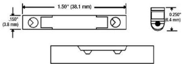

1.3 3M
TM Fibrlok TM Assembly Tool 2501
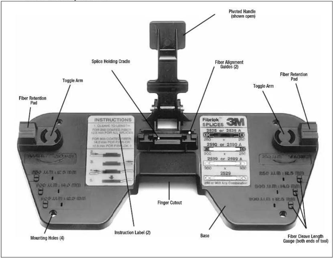
1.4 Tools and Materials Required are as follows:
- 3M™ Fibrlok™ Assembly Tool 2501
- Plastic coating (buffer) stripper
• Reagent-grade isopropyl alcohol - Lint-free wipes
- Cleaver
• 3M Fibrlok II video instructions (optional)
• 3M Fibrlok Tool Kit (optional)
1.5 Some compatible 3M Fiber Splice Tray product numbers are: 2522, 2524, 2523, 2527
2.0 Splicing Set-Up
2.1 The splicing area should be clean, dry and well-lit. A clean, well-organized splicing area will improve splice efficiency and minimize the risk of contamination of fibers or splices.
2.2 Open the buffer tubes, expose and clean the fibers per your company practice.

Note: Storage, use and disposal of isopropyl alcohol should be per your company health, safety and environmental instructions. Refer to solvent label or Safety Data Sheet.
2.3 See Section 6.0 for recommended procedures for fiber organization and splice storage.

2.4 Remove 3M ™ Fibrlok ™ II Universal Splice 2529 from its protective package. Load the splice into the assembly tool by pressing firmly at the ends of the splice.
Note: Carefully follow health, safety and environmental information on Fibrlok II splice label or Safety Data Sheet.

CAUTION
May cause minimal eye irritation.
Contains: Phenylmethyl silicone (63148-58-3), hydrophobic silica (68611-44-9).
Precautions: Avoid eye contact. Wash hands before eating or smoking.
First Aid:
Eye Contact: Immediately flush eyes with plenty of water while holding eyelids open and continue flushing for ten minutes. Call a physician.
Skin Contact: Wash with soap and water.
Production Information Source: Material Safety Data Sheet or 3M Company,
St. Paul, MN 55144-1000, (612) 733-111-: Operator 55
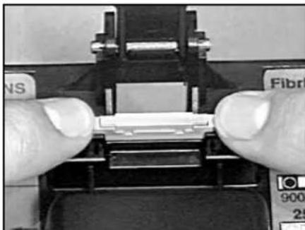
2.5 If using the 3M "Fibrlok" Assembly Tool 2501, rotate the toggle arms for the appropriate fiber size.
3.0 Fiber Preparation
3.1 Remove the minimum length of fiber required to prepare and splice the fibers.
3.2 Strip approximately 1 to 2 inches (25 mm to 51 mm) of plastic coating from the fiber using a mechanical stripper.
Note: The stripper should be in good operating condition to prevent scratches or other damage to the glass cladding.

3.3 Clean the bare glass by pulling the fiber through an alcohol soaked lint-free wipe. This will remove any fragments or dirt remaining on the fiber.
Note: Do not wipe the fibers more than two times, and limit the time that the bare fiber is exposed to the atmosphere.
Note: Carefully follow health, safety and environmental information on container label or Data Sheet for isopropyl alcohol being used.

3.4 Cleave the fiber to 12.5 mm ±0.5 mm (0.492 ±0.020 inches).
Important: The 3M FibrlokII Universal Splice 2529 uses a cleave length of 12.5mm± 0.5mm (0.492 ± 0.020 inches) for both 250 and 900 coated fibers.
Note: The cleaver should be in good operating condition and used in accordance with the manufacturer's instructions. It is recommended that the cleaver provide a consistent cleave-to-coating length within ±0.5 mm. In addition, standard cleavers should produce cleaved ends within 2° of perpendicular and free of major defects. Cleavers specifically designed to produce controlled, angled cleaves of greater than 2° , but not more than 6° , may also be used with the 3M FibrlokSplice.
3.5 Check the cleave length using the 12.5 mm cleave length gauges on the 3M Fibrlok Assembly Tool 2501. Adjust the cleaver to provide the prescribed cleave lengths. Check cleave lengths periodically during subsequent splicing operations.
Note: Do not allow cleaved end to contact tool. Do not clean the fibers again after they have been cleaved.

4.0 Splice Assembly
4.1 Push the fiber down into the fiber retention pad on the proper side of the splice.
Note: Hold the coated portion of the fiber ONLY. Do not allow the cleaved end to contact any surface before insertion into the splice.

4.2 Grasp the coated fiber about .25 inches (6 mm) from the bare glass and move the fiber end onto the fiber alignment guide on the assembly tool such that the end is resting on the alignment guide outside of the splice.
Note: When splicing 250 μm to 900 μm coated fiber, always insert the 250 μm coated fiber first.
Note: Fiber should be placed in the retention pad and inserted into the splice immediately following cleaning to minimize exposure to the atmosphere and reduce the risk of contamination.
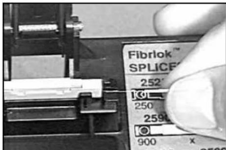
Note: Push fiber straight into fiber alignment guide, NOT AT AN ANGLE.

4.3 Gently continue pushing the fiber into the splice until resistance is felt. When fully inserted, the first fiber should be straight or have a slight bow-up to .1 inch (3 mm).
Note: If properly inserted, bare glass should not be visible outside of splice. If bare glass is visible, pull back slightly on fiber and continue insertion until resistance is met. Never fully remove fibers from splice after initial insertion. Do not pull on fiber after it has been properly inserted.

4.4 Prepare second fiber (strip, clean and cleave) as described in Section 3.
4.5 Lay fiber into foam retention pad and begin to insert the fiber end into the splice, as in 4.01 and 4.02.

4.6 Gently push the second fiber in small increments straight through the alignment guide into the fiber entry port. As the coating of the second fiber enters the fiber entry port, watch for the bow in the first fiber to increase. This occurs when the end face of the second fiber contacts the first fiber and pushes the first fiber slightly back out of the splice. Continue gently pushing the second fiber until it meets resistance.
4.7 Following proper insertion, the second fiber will be approximately straight, but may have up to a .1 inch (3 mm) maximum bow. At this point, the first fiber will have a larger bow than the second fiber and larger than it had initially.

4.8 Push the first fiber back against the second fiber until there are equal bows in both fibers.
Note: Do not pull on either of the fibers following establishment of the bows in the first and second fibers. The fiber ends must be held together by the compressive forces induced by the bows to produce a low loss splice.
If fiber bows are NOT observed to move as described, repeat steps 4.02 - 4.07 of Splice Assembly but DO NOT fully remove fibers from the splice. If bow movement is still not observed, remove fibers, strip, clean and re-cleave, checking for proper cleave length. Re-splice per splicing procedure using a new splice.
Do not attempt to “tune” or optimize the splice as this may result in higher splice loss. The 3M™ Fibrlok™ II Splice is not designed to be “tuned.” Fiber alignment does not occur until the splice is activated.
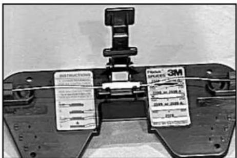
4.9 Pivot the handle of the 3M ™ Fibrlok ™ Assembly Tool 2501 down until it contacts the cap of the Fibrlok splice. Squeeze the handle of the assembly tool as shown in order to close cap and actuate the splice. When possible, secure the tool to a work surface for added support. A snap sound will be heard when the splice is actuated.

4.10 Remove the 3M ™ Fibrlok ™ Splice from the assembly tool by first removing the fibers from the foam retention pads and then lifting the splice from the splice holding cradle.
Note: In the event a splice must be refabricated, simply cut the fibers at each end of the splice (this will remove 1-1/2" of fiber from the loop) and re-splice per instructions. Splice fabrication will require a new splice and a length of 2 inches on each fiber.
Note: Do not remove fibers and re-use 3M Fibrlok Splices.

5.0 For splicing any combination of 250 μm coated fiber and 900 μm buffered fiber:
5.1 Keep 3M Fibrlok Splices clean. Do not remove splices from sealed cavity until ready to use.
5.2 Place the splice into splice holding cradle in assembly tool.

5.3 If using the 3M ™ Fibrlok Assembly Tool 2501, be sure that the retention pad toggle arms are in the inward position for 250 µ m fibers and in the outward position for splicing 900 µ m fibers.


5.4 Strip and cleave first fiber to 12.5 mm ± 0.5 mm (0.492 ± 0.20 in).
5.5 Taking care not to touch fiber end face, place fiber into foam retention pad.
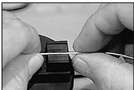
6.0 Fiber Repositioning
6.1 If high loss is observed after splice has been actuated, it is possible that the fiber ends are separated. In this case, lift the splice cap and reposition fiber ends, as instructed below.
Note: Do not completely remove fiber from Fibrlok splices.
6.2 While the splice is in the splice holding cradle, insert the short prongs of the 3M ™ Fibrlok ™ II Splice cap lifter into the two holes on the side of the splice. The cap lifter will be at an angle to the splice. The long prongs will be resting against the top of the splice cap.
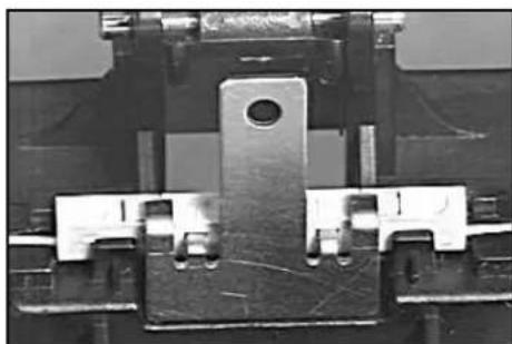
6.3 Slide the bottom of the cap lifter inward until it is in a vertical position, lifting the splice slightly out of the cradle.

6.4 Hold the cap lifter in place with one hand and push down on the ends of the splice with the other hand. This action should reseat the splice into the holding cradle and lift the cap at the same time.
6.5 Repeat fiber centering and splice actuation (See step 4.06 - 4.09). If after two attempts an acceptable splice loss is not obtained, remove fiber, strip, clean and re-cleave. Re-splice using a new splice.

7.0 Fiber Organization and Splice Storage
7.1 When storing fiber slack in a splice tray, the spliced fiber ends will twist one full turn for each full loop of fiber being stored. This rotation places stress on the fibers. This rotational stress makes fiber organization more difficult and may affect fiber/splice performance, particularly in 900 µ m coated fibers. The stiffness of the 900 µ m fiber does not distribute this stress in the same manner as 250 µ m coated fiber.
Note: The following procedure must be followed when splicing 900 µ m coated fibers and will improve fiber organization when splicing all fiber types.
7.2 Secure the buffer tubes of the fibers to be spliced to the tray so that the fibers are free to rotate through the point of attachment.
7.3 Select the first two fibers to be spliced and lay them into the tray. Trim the fibers so they are the right length for splicing plus approximately 1 to 2 inches (2.5 to 5cm ) for fiber end preparation.

7.4 Place the splice assembly tool close to or on top of the splice tray. Match the orientation of the tool to that of the splice holder or tray whenever possible.

7.5 Remove the minimum amount of fiber required for fiber preparation and splicing. Remove less than one loop if possible.
7.6 Prepare fibers and complete splice as described in Section 3 and 4.
7.7 Carefully lay the splice on top of the holder without securing the splice into the holder.
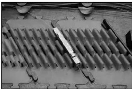
Note: In order to minimize torsion on the fiber, perform the following:
7.8 For 250 to 250µm and 900 to 900µm splices:
a. Store the shorter of the two fibers in the tray.
b. Observe how the splice lays in its relaxed state. Rotate the splice through the smallest possible angle to install it in the tray.
c. Store the second fiber.
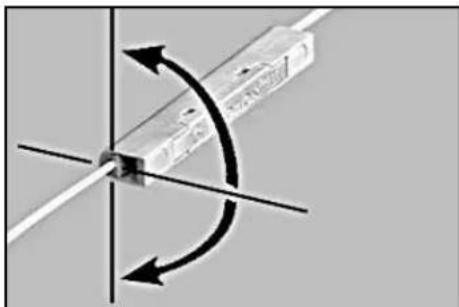
7.9 For 250 to 900µm splices:
a. Store the 900 μm fiber first.
b. Grasping the splice by the 900 µm fiber, observe how the splice lays in its relaxed state. Rotate the splice through the smallest possible angle to install it in the tray.
c. Store the 250 μm fiber.

8.0 Splicing Accessories
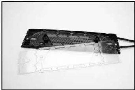
8.1 The 3M ™ Fiber Splice Organizer Tray 2523 holds up to 24 Fibrlok splices and provides excellent fiber and splice organization. Easily installed, the tray will accommodate up to eight buffer tubes holding up to 48 fibers (250 µ m or 900 µ m coated fibers) and can be adapted for fusion splice storage.
8.2 The 2524 splice tray fits and mounts into the 3MTM Fiber Optic Splice Closure 2178. It is also compatible with a variety of non-3M closures.
8.3 3M ™ Fibrlok ™ Splice Kits provide all the tools necessary for the assembly of the Fibrlok splice. Fibrlok splice kits are available with or without a fiber optic cleaver.

Splice Kits 3M ID
2559 Splice Kit 80-6113-2375-1
2559-C Splice Kit with 2534 Cleaver 80-6113-2376-9
Splice Kit Components (available separately) 3M ID
3M™ Fibrlok™ Assembly Tool 2501 80-6105-8187-0
Aramid Yarn Snips 80-6113-0462-9
Lint Free Cloth (100/pkg) 80-6104-4324-6
2534 Cleaver 80-6113-2377-7
Instruction Manual 78-8128-0163-3-G
3M and Fibrlok are trademarks of 3M Company.
Important Notice
All statements, technical information, and recommendations related to 3M's products are based on information believed to be reliable, but the accuracy or completeness is not guaranteed. Before using this product, you must evaluate it and determine if it is suitable for your intended application. You assume all risks and liability associated with such use. Any statements related to the product which are not contained in 3M's current publications, or any contrary statements contained on your purchase order shall have no force or effect unless expressly agreed upon, in writing, by an authorized officer of 3M.
Warranty; Limited Remedy; Limited Liability.
This product will be free from defects in material and manufacture for a period of one (1) year from the time of purchase. 3M MAKES NO OTHER WARRANTIES INCLUDING, BUT NOT LIMITED TO, ANY IMPLIED WARRANTY OF MERCHANTABILITY OR FITNESS FOR A PARTICULAR PURPOSE. If this product is defective within the warranty period stated above, your exclusive remedy shall be, at 3M's option, to replace or repair the 3M product or refund the purchase price of the 3M product. Except where prohibited by law, 3M will not be liable for any direct, indirect, special, incidental or consequential loss or damage arising from this 3M product, regardless of the legal theory asserted.
3M
Communication Markets Division
6801 River Place Blvd.
Austin, TX 78726-9000
1-800-426-8688
www.3M.com/Telecom
Please Recycle. Printed in USA.
© 3M 2015. All Rights Reserved.
78-8128-0163-3-G

- 3M™ FIBRLOK™ II UNIVERSAL OPTICAL FIBER SPLICE 2529
- INSTRUCTIONS
- 1.0 GENERAL
- 1.4 TOOLS AND MATERIALS REQUIRED ARE AS FOLLOWS
- 2.0 SPLICING SET-UP
- CAUTION
- 3.0 FIBER PREPARATION
- 4.0 SPLICE ASSEMBLY
- 5.0 FOR SPLICING ANY COMBINATION OF 250 ΜM COATED FIBER AND 900 ΜM BUFFERED FIBER
- 6.0 FIBER REPOSITIONING
- 7.0 FIBER ORGANIZATION AND SPLICE STORAGE
- 8.0 SPLICING ACCESSORIES
- SPLICE KITS 3M ID
- SPLICE KIT COMPONENTS (AVAILABLE SEPARATELY) 3M ID
- IMPORTANT NOTICE
- WARRANTY; LIMITED REMEDY; LIMITED LIABILITY
- 3M
- COMMUNICATION MARKETS DIVISION
Brand : 3M
Model : 2529
Category : Pliers