
VF-402-KIT - Audio/video extension Planet - Free user manual and instructions
Find the device manual for free VF-402-KIT Planet in PDF.


| Product Type | Audio/Video Extension Kit (Transmitter + Receiver) |
| Brand | Planet |
| Model | VF-402-KIT |
| Dimensions (each unit) | Approximately 70 x 50 x 25 mm |
| Weight (total pair) | About 100 g |
| Power Supply | 5V DC via USB (adapter not included) |
| Video Resolution Support | Up to 1080p @ 60Hz |
| Transmission Medium | Cat5e/6 Ethernet cable |
| Maximum Transmission Distance | Up to 50 meters (164 feet) |
| IR Extension | Supports IR pass-through for remote control |
| Audio Support | Digital audio (HDMI) and analog via optional adapter |
| Connector Type (Input/Output) | HDMI Type A (female) on both units |
| Operating Temperature | 0°C to 45°C (32°F to 113°F) |
| Storage Temperature | -10°C to 60°C (14°F to 140°F) |
| Maintenance | Wipe with a dry cloth; avoid liquids and excessive heat |
| Safety Precautions | Do not disassemble; keep away from moisture and children |
| Spare Parts & Reparability | No user-serviceable parts; replace entire unit if defective |
| General Information | Compatible with HDMI 1.3 and HDCP 1.2; plug-and-play installation |
Frequently Asked Questions - VF-402-KIT Planet
User questions about VF-402-KIT Planet
0 question about this device. Answer the ones you know or ask your own.
Ask a new question about this device
Download the instructions for your Audio/video extension in PDF format for free! Find your manual VF-402-KIT - Planet and take your electronic device back in hand. On this page are published all the documents necessary for the use of your device. VF-402-KIT by Planet.
USER MANUAL VF-402-KIT Planet
4-Channel Video over Fiber Bundle Kit
VF-402-KIT
User's Manual
Copyright
Copyright © 2017 by PLANET Technology Corp. All rights reserved. No part of this publication may be reproduced, transmitted, transcribed, stored in a retrieval system, or translated into any language or computer language, in any form or by any means, electronic, mechanical, magnetic, optical, chemical, manual or otherwise, without the prior written permission of PLANET.
PLANET makes no representations or warranties, either expressed or implied, with respect to the contents hereof and specifically disclaims any warranties, merchantability or fitness for any particular purpose. Any software described in this manual is sold or licensed "as is". Should the programs prove defective following their purchase, the buyer (and not PLANET, its distributor, or its dealer) assumes the entire cost of all necessary servicing, repair, and any incidental or consequential damages resulting from any defect in the software. Further, PLANET reserves the right to revise this publication and to make changes from time to time in the contents hereof without obligation to notify any person of such revision or changes.
All brand and product names mentioned in this manual are trademarks and/or registered trademarks of their respective holders.
Federal Communication Commission Interference Statement
This device has been tested and found to comply with the limits for a Class B digital device, pursuant to Part 15 of FCC Rules. These limits are designed to provide reasonable protection against harmful interference in a residential installation. This device generates, uses, and can radiate radio frequency energy and, if not installed and used in accordance with the instructions, may cause harmful interference to radio communications. However, there is no guarantee that interference will not occur in a particular installation. If this device does cause harmful interference to radio or television reception, which can be determined by turning the device off and on, the user is encouraged to try to correct the interference by one or more of the following measures:
- Reorient or relocate the receiving antenna.
- Increase the separation between the device and receiver.
- Connect the device into an outlet on a circuit different from that to which the receiver is connected.
- Consult the dealer or an experienced radio technician for help.
FCC Caution
To assure continued compliance, use only shielded interface cables when connecting to computer or peripheral devices. Any changes or modifications not expressly approved by the party responsible for compliance could void the user's authority to operate the device.
This device complies with Part 15 of the FCC Rules. Operation is subject to the
following two conditions: (1) This device may not cause harmful interference, and (2) this device must accept any interference received, including interference that may cause undesired operation.
Federal Communication Commission (FCC) Radiation Exposure Statement
This device complies with FCC radiation exposure set forth for an uncontrolled environment. In order to avoid the possibility of exceeding the FCC radio frequency exposure limits, human proximity to the antenna shall not be less than 20 cm (8 inches) during normal operation.
CE Mark Warning
CE Warning: This equipment is a Class B product. In a domestic environment, this product may cause radio interference, in which case the user may be required to take adequate measures.
Safety Instructions
This device is designed with the utmost care for the safety of those who install and use it. However, special attention must be paid to the dangers of electric shock and static electricity when working with electrical device. All guidelines of this and the computer manufacturing must therefore be allowed at all times to ensure the safe use of the device.
National Restrictions
This device is intended for home and office use in all EU countries (and other countries following the EMC directive 2014/30/EU and LVD directive 2014/35/EU).
WEEE Regulation

To avoid the potential effects on the environment and human health as a result of the presence of hazardous substances in electrical and electronic device, end users of electrical and electronic device should understand the meaning of the crossed-out wheeled bin symbol. Do not dispose of WEEE as unsorted municipal waste and have to collect such WEEE separately.
Revision
User's Manual of 4-channel Video over Fiber Bundle Kit (VF-402-T + VF-402-R)
Model: VF-402-KIT
Rev: 2 (May, 2017)
Part No. EM-VF-402-KIT(v2)_v2.0
Table of Contents
Chapter 1. Product Introduction ...... 5
1.1 Package Contents.... 5
1.2 Product Description.... 5
1.3 Application....8
1.4 Product Features 9
1.5 Product Specifications .... 10
1.6 Dimensions of Installing....12
Chapter 2. Hardware Description....13
2.1 Panel Overview ...... 13
Chapter 3. Installation....15
3.1 Limitation .... 15
3.2 Preparation before Installing....15
3.3 Order for installation....16
3.4 Stand-alone Installation 16
3.5 Rack and Wall Mounting....17
Chapter 4. Precautions....19
Chapter 5. Troubleshooting....20
Chapter 1. Product Introduction
1.1 Package Contents
Check the contents of your package for the following parts:
● VF-402-T - Video over Fiber Media Converter (Transmitter) x 1
● VF-402-R - Video over Fiber Media Converter (Receiver) x 1
● 5V / 2A Power Adapter x 2
- User's Manual x 1

If any of the above items are missing, please contact your dealer immediately.
1.2 Product Description
Reliable Long Distance Solution for Analog Surveillance System
To deploy AHD/CVI/TVI/CVBS analog camera in a remote place efficiently and provide high video quality and reliable signal, PLANET has developed the video over fiber media converter kit, VF-402-KIT, which is ideal for extending the distance and signal conversion by transmitting the AHD/CVI/TVI/CVBS video and data over the fiber-optic cable. Adopting the intelligent encoding/decoding technology and with the compact box, the VF-402-KIT CCTV over fiber media converter enables the videos to be delivered in high quality up to 20km long in distance.

Fiber Optic Communication for Video and Serial Data
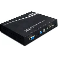
The VF-402-KIT consists of a Video Transmitter and a Video Receiver:
● VF-402-T: 4-channel Video over Fiber Transmitter
● VF-402-R: 4-channel Video over Fiber Receiver
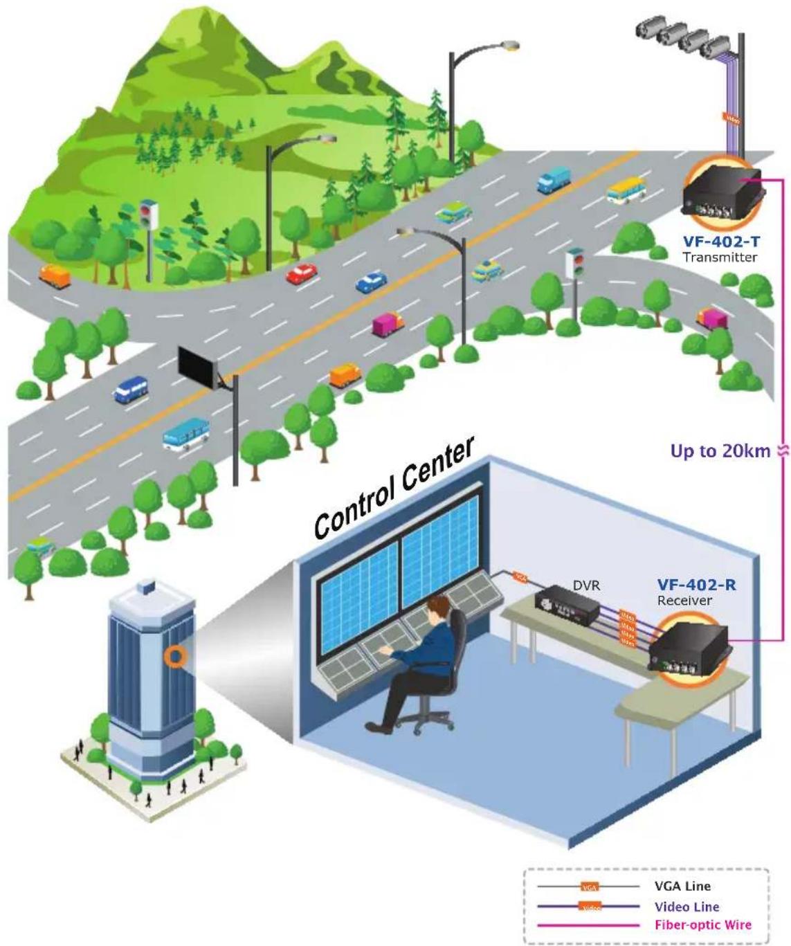
The VF-402-KIT is a digital fiber-optic transmission system that brings users a cost-effective solution for transmission of 4-channel uncompressed digital video and one reverse RS485 async data over one single fiber cable. The VF-402-KIT is an adjustable free device providing high-quality and real-time video transmission. It can be widely used in intelligent transportation systems (ITS), traffic surveillance, security monitoring, automation control, intelligent residential districts, etc.
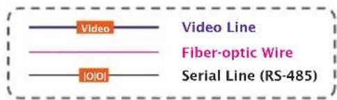
![graph LR A["Analog Camera"] --> B["Video Line"] B --> C["VF-402-T Transmitter"] C --> D["Up to 20km"] D --> E["VF-402-R Receiver"] E --> F["DVR / Monitor"] style A fill:#f9f,stroke:#333 style B fill:#ccf,stroke:#333 style C fill:#cfc,stroke:#333 style D fill:#fcc,stroke:#333 style E fill:#cff,stroke…](/content/2026/06/1268220/images/9da78ae5d8ba9593a4de4bb27e7e71b219409eeda3a9deca1ec709494061875e.jpg)
![graph LR A["Speed Dome"] -->|Video| B["VF-402-T Transmitter"] B -->|Up to 20km| C["VF-402-R Receiver"] C -->|Video| D["DVR / Monitor"] C -->|Data| E["Control Keyboard"]](/content/2026/06/1268220/images/1352c5fa88f3d5b9886b29bd685b6c195d4b032ab6e032dc3ed659fffb4e8148.jpg)
Industrial Monitoring Systems
The industrial-level VF-402-KIT's super wide temperature ranges from -20 to 70 degrees C, applicable to all kinds of environments. It supports hot plugging and its 4-channel video adopts the full digital video non-compression and Gigabit fiber optic transmission technology that brings distortion-free videos over a long-distance fiber cable. Thus, it can observe working condition visually with LED. It can be a standalone or rack-mounted structure, and is simple to operate with no field adjustment needed.
1.3 Application
The VF-402-KIT consists of 4-channel video over fiber optical transceiver and receiver to transmit video and RS485 signal through a reliable single mode or single fiber link. It is an ideal cost-effective solution for surveillance system that requires high display quality and high-performance signal transmission over long distances. The VF-402-KIT can be installed easily by way of "Plug and Play", meaning the operator does not need to configure the pair of the video over fiber transmission in advance.
![graph TD subgraph_VF-402-T_Transmitter["VF-402-T Transmitter"] A["IR Dome"] --> B["Analog Camera"] B --> C["Analog Camera"] C --> D["Video Line"] D --> E["FactoryTrain Station"] E --> F["Speed DomeLong Distance IR"] F --> G["Analog Camera"] G --> H["Analog Camera"] H --> I["Video Line"] I --> J["VR-…](/content/2026/06/1268220/images/d020b0d4ec7cebba07e3b9a4caa9a67cabc7549f1d34c1b2b8ec135199fa9e4c.jpg)
Typical Applications
● Intelligent Transportation Systems (ITS)
- Toll Collection
● Traffic Surveillance
● Air Traffic Management (ATM)
Rail Signaling
● Perimeter Alarms and Area Monitoring
● Telemedicine and Teleconference
- Industrial Surveillance
● Intelligent Building
CCTV Network
1.4 Product Features
● Compliant with hybrid video (AHD/TVI/CVI/CVBS)
● 20km long-distance data transmission
● Fiber optic transmission of four video signals on one fiber with RS485 data signals which may be one way with the video or optional duplex
● Status indication for power supply, optical signal and video
● High-speed synchronous digital transmission technology
● Effective against electromagnetic interference, radio frequency interference, 6KV high-level lightning protection design
● Guarantees safe transmission under poor electromagnetic environment
● Maximum tolerable link loss for single mode single fiber is 0.35dB/km
● Video bandwidth of 60MHz, SNR>67dB
● Super wide temperature range from -20 to 70 degrees C
1.5 Product Specifications
| Model VF-402-T VF-402-R | ||
| Video Characteristics | ||
| Video Channel 4-channel bi-direction | ||
| Video Connector BNC | ||
| Supported Video Type | 1080p: AHD/TVI/CVI480p: CVBS | |
| Video Input/Output Impedance 75ohm/unbalanced interface | ||
| Video Input/Output Voltage 1.0 Vpp / typical peak to peak value | ||
| Video Bandwidth 25 to 60MHz | ||
| Video Digital Bit Width 8/10 bit | ||
| Differential Gain (DG) <2% (typical value) | ||
| Differential Phase (DP) <2° (typical value) | ||
| SNR-weighted Scheme >67dB (typical value) | ||
| Data Interface | ||
| Data Channel 4 channels | ||
| Physical Protocol RS485 | ||
| Operation Mode Simplex | ||
| Data Connector | 4-pin terminal block with screw clamps | |
| Data Rate | DC-150Kbps | |
| Data Distance | RS485: 0-20km | |
| BPS | 0-115.2Kbps | |
| Bit Error Rate (BER) | <10-9 | |
| Optical Interface | ||
| Optical Connector | FC | |
| Fiber Type | Single-mode, single fiber | |
| Distance | 20km for single mode | |
| Optical Wavelength | TX: 1310nmRX: 1550nm | TX: 1550nmRX: 1310nm |
| Transmitter Coupled Power | Max.: 0 dBmMin.: -8 dBm | |
| Receive Sensitivity | -22 dBm | |
| Link Budget | From 15dB to 20dB at 1310nm or 1550nm | |
| Cable | 9/125μm single-mode cable | |
| Hardware Specifications | |
| LED Indicators | PowerEach channelLink (fiber optic) |
| Dimensions (W x D x H) 157 × 1 | 16.5 × 48 mm |
| Weight 580g | |
| Power Requirement 5V DC, 2A | |
| Chassis Current Consumption | 1.10 amp for 4-channel video and 1-channel data |
| Mechanical Metal | |
| Standards Conformance | |
| Regulatory Compliance FCC, CE | |
| Environment | |
| Operating | Temperature: -20 ~ 70 degrees CRelative Humidity: 0 ~ 95% (non-condensing) |
| Storage | Temperature: -40 ~ 85 degrees CRelative Humidity: 0 ~ 95% (non-condensing) |
| Standard Accessories | |
| Packet Contents | VF-402-T x 1VF-402-R x 1User's Manual x 15V/2A power adapter x 2 |
1.6 Dimensions of Installing

Chapter 2. Hardware Description
2.1 Panel Overview
Front Panel:
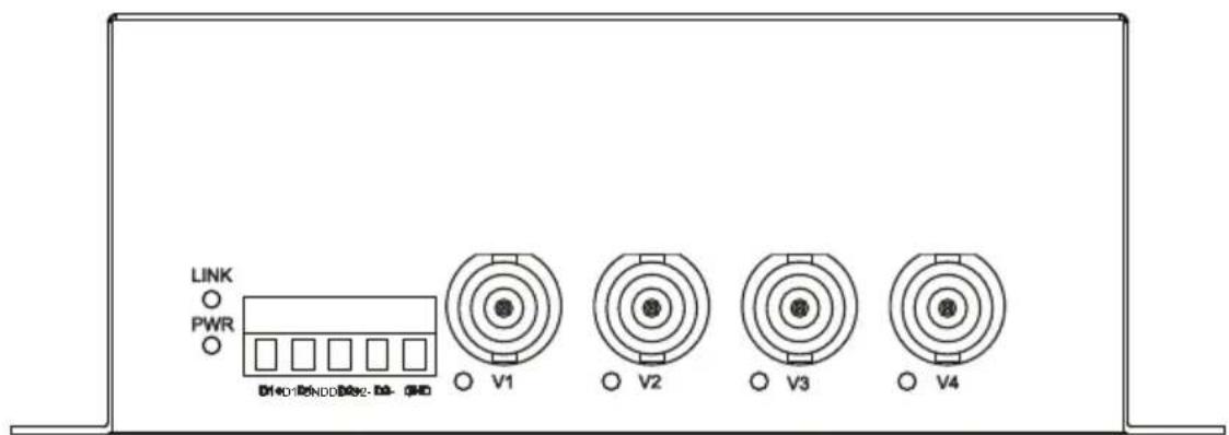
■ Video interface
| Item Description | |
| VIDEO/V1...V4 Video input | interface |
■ LED definition
PWR: Power indicators -- when powered on, PWR LED is on.
LNK: Optical link indicator -- after connecting the fiber connector, the indicator will show green when optical signal is detected. But the indicator will be off when optical signal is not detected.
V1\~V4: Video indicator -- the indicator will show green when video signal is detected. But the indicator will be off when there is no video signal.
Rear Panel:
There is a power interface on the rear panel; the description of each is as follows:
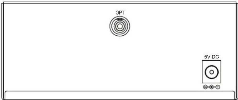
Power Supply
| Power supply | |
| Output 5V DC, 2A |
| Note | 1. The device is a power-required device, meaning it will not work till it is powered. If your networks should be active all the time, please consider using UPS (Uninterrupted Power Supply) for your device. It will prevent you from network data loss or network downtime.2. In some areas, installing a surge suppression device may also help to protect your converter from being damaged by unregulated surge or current to the converter or the power adapter. |
■ Fiber interface
| Item Description | |
| FIBER/OPT FC-type fiber interface. | |
| Note | After the VF-402-KIT is powered on, wait for at least 15 second before connecting the connector to the optical fiber port or else the connector may be damaged or you may get an electric shock. |
Chapter 3. Installation
This section describes how to install your VF-402-KIT Video over fiber and make connections to the converter. Please read the following topics and perform the procedures in the order being presented. The hardware installation of PLANET VF-402-KIT Video over fiber Converter does not need software configuration. To install your VF-402-KIT on a desktop or shelf, check the following sections.
3.1 Limitation
The Video over fiber Converter does not require any software configuration. Users can immediately use any feature of this product simply by plugging in the cable and powering it on. There is some key limitation on the video over fiber converter. Please check the following items:
● The device is used for Point-to-Point connection only (transmitter to receiver) and allows video and data to work on the same optical fiber patch cord.
- It comes with the 75 ohm BNC connector. The distance will change by the quality of coaxial cables.
3.2 Preparation before Installing
In order to ensure your normal use, please make sure that you are using the right optical path, right signal, good power grounding, and so on. We guarantee all of our products are subject to strict test and aging, and we simulate field environment operation tests. Please contact us if there is any problem.
(1) Please carefully read the user manual of the product before installing.
(2) Please carefully read the safety instructions.
(3) Optical transceiver equipment shall not be disassembled by anyone without authorization.
(4) Check the product model tag stuck outside the cabinet (T for transmitter, R for receiver) to prevent incorrect installation.
(5) Optical transmitter is the transmitting part; its function is to convert the video, audio and data, switching value, Ethernet, etc into optical signals and then transmitting through optical fiber cable. Therefore, the device that is connected to this type of optical transmitter can have cradle head with cameras.
(6) Optical receiver is the receiving part; its function is to convert the video, audio and data, switching value, Ethernet, etc into electrical signals. Therefore, the device that is connected to this type of optical receiver can be a displayer or matrix.
(7) The relation of the video of optical transmitter and optical receiver is one-to-one, which means V1\~V4 of optical transmitter is one-to-one to V1\~V4 of optical transmitter.
3.3 Order for installation
(1) Connect the interface of optical transmitter with camera or speed dome. Then connect the optical fiber and the power supply.
(2) Connect the interface of optical receiver with video interface, monitor, video matrix and displayer. Then connect the optical fiber and the power supply.
(3) Insert the power supply according to the configuration of device, correctly accessing peripheral attachment. Check optical fiber, data cable, video cable, etc. on the basis of wiring diagram (accompanied with each set of optical transceiver) of optical transceiver.
(4) After all the connection and passing inspection, power on to see if device runs normally.
(5) Please install the lightning protection facilities and make sure the ground connection is good when installing this device in the open air.
3.4 Stand-alone Installation
To install a VF-402-T/VF-402-R stand-alone on a desktop or shelf, simply complete the following steps:
(1) Turn off the power of the analog camera/monitor to which the VF-402-T/VF-402-R will be attached.
(2) VF-402-T (Transmitter): Connect coaxial cable from analog camera to video BNC port of the VF-402-T.
(3) Attach FC single mode fiber cable from the VF-402-T to VF-402-R in the remote side.

After the VF-402-KIT is powered on, wait for at least 15 seconds before connecting the connector to the optical fiber port or else the connector may be damaged or you may get an electric shock.
(4) VF-402-R (Receiver): Connect coaxial cable from monitor/DVR to Video BNC port of the VF-402-R.
(5) Connect the 5V DC power adapter to the VF-402-T/VF-402-R and verify that the Power LED lights up.
(6) Turn on the power of the analog camera/monitor; the video LED (green) should be lit when all cables are connected.
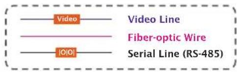
![graph LR A["Speed Dome"] -->|Video| B["Transmitter"] B -->|Up to 20km| C["Receiver"] C -->|Video| D["DVR / Monitor"] C -->|I/OI| E["Control Keyboard"]](/content/2026/06/1268220/images/921917ee540ab6cd2321cf50a06d2f51a8fdd1fbe778bd0f5445dca8c3320a72.jpg)
3.5 Rack and Wall Mounting
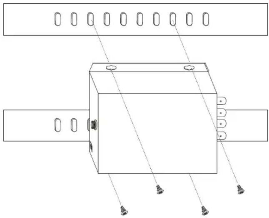
Rack Mount: Make sure device is tightly mounted on the track
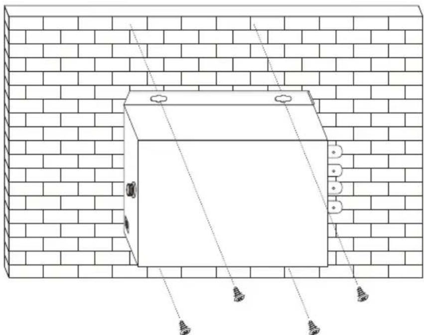
Wall Mount: Mount device on the wall with screws
Chapter 4. Precautions
(1) Insert fiber rightly into the fiber interface; avoid breaking off fiber because of applying too much force. The rolling diameter shall not be too short (not less than 20cm).
(2) Fasten the retaining screw after connecting terminal blocks.
(3) Do not remove the dust cap before installation. Make sure to prevent dirt and other things from getting into port or else the loss of optical signal will be increased and the transmission quality will be affected.
(4) Note that optical transceiver matches well when installing device so as to avoid work obstruction because of a different optical power, data interface and transmission distance. Pay attention to the differences of transmitter and receiver.
(5) Data interface is terminal block. To ensure good contact, it is required to insert interface after thinning. Please use good-quality stranded and shielded copper core, such as Belden, etc.
Chapter 5. Troubleshooting
| Question Answer | or Solution |
| Power supply indicator is off. | Check if the power plug is tightly connected and check the fuse wire of chassis. |
| Abnormal video data. | Check if local interference, poor-quality monitor and optical output power are normal and in the range of receiving sensitivity. |
| Irregular horizontal grain or video images. | Incorrect video input synchronization -- check if the grounding electrical level is equal, especially the grounding electrical level of the power of optical transceiver, and input and output device; check the connection of video lines and if the input signal complies with standard. |
| All indicators are off. | Check if the power adapter works normally, modules are completed, and the slots are right. |
| Video indicator of optical receiver flashes. | Receiver is not receiving the right optical signal; check if the link loss rate is normal. The rolling diameter is too short (less than 20cm); impurities on ceramic interface (gently clean it with alcoholic cotton). |
| Video indicator of optical transmitter is off. | Optical transceiver is not receiving video signal; need to check the video input. |
| Snowflakes emerge in output video of receiver. | Bit error in transmission -- check if the link loss is too much; the rolling diameter cannot be too short (not less than 20cm); transmission is unstable because operating temperature is too high. |
| Abnormal data. | Check if data protocol is right (if using RS232 transmitting RS485, etc.), the transmitting direction is right (forward and backward or bidirectional), connection is right or not (data is positive or negative, transmitting or receiving), and the data input is right or not. |

- 4-CHANNEL VIDEO OVER FIBER BUNDLE KIT
- COPYRIGHT
- FEDERAL COMMUNICATION COMMISSION INTERFERENCE STATEMENT
- FCC CAUTION
- FEDERAL COMMUNICATION COMMISSION (FCC) RADIATION EXPOSURE STATEMENT
- CE MARK WARNING
- SAFETY INSTRUCTIONS
- NATIONAL RESTRICTIONS
- WEEE REGULATION
- REVISION
- TABLE OF CONTENTS
- CHAPTER 1. PRODUCT INTRODUCTION ...... 5
- CHAPTER 2. HARDWARE DESCRIPTION....13
- CHAPTER 3. INSTALLATION....15
- CHAPTER 4. PRECAUTIONS....19
- CHAPTER 5. TROUBLESHOOTING....20
- CHAPTER 1. PRODUCT INTRODUCTION
- 1.1 PACKAGE CONTENTS
- 1.2 PRODUCT DESCRIPTION
- RELIABLE LONG DISTANCE SOLUTION FOR ANALOG SURVEILLANCE SYSTEM
- FIBER OPTIC COMMUNICATION FOR VIDEO AND SERIAL DATA
- INDUSTRIAL MONITORING SYSTEMS
- 1.3 APPLICATION
- TYPICAL APPLICATIONS
- 1.4 PRODUCT FEATURES
- 1.6 DIMENSIONS OF INSTALLING
- CHAPTER 2. HARDWARE DESCRIPTION
- 2.1 PANEL OVERVIEW
- FRONT PANEL
- VIDEO INTERFACE
- LED DEFINITION
- REAR PANEL
- POWER SUPPLY
- FIBER INTERFACE
- CHAPTER 3. INSTALLATION
- 3.1 LIMITATION
- 3.2 PREPARATION BEFORE INSTALLING
- 3.3 ORDER FOR INSTALLATION
- 3.4 STAND-ALONE INSTALLATION
- 3.5 RACK AND WALL MOUNTING
- CHAPTER 4. PRECAUTIONS
Brand : Planet
Model : VF-402-KIT
Category : Audio/video extension