
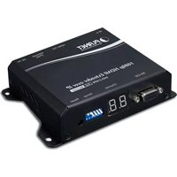
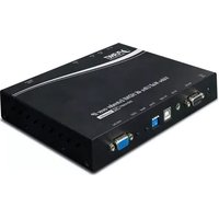
VF-102SC-KIT - Audio/video extension Planet - Free user manual and instructions
Find the device manual for free VF-102SC-KIT Planet in PDF.


| Product Type | HDMI Extender Kit |
| Model | VF-102SC-KIT |
| Brand | Planet |
| Video Interface | HDMI 1.4 |
| Max Resolution | 1080p@60Hz |
| Transmission Distance | Up to 50m (164ft) over Cat5e/6 |
| Audio Support | PCM, Dolby Digital, DTS |
| IR Pass-through | Yes (20-60kHz) |
| Power Supply | 5V DC, 1A (USB powered) |
| Dimensions (each unit) | 70 x 50 x 20 mm |
| Weight (each unit) | 50 g |
| Material | ABS plastic |
| Color | Black |
| Operating Temperature | 0°C to 50°C |
| Usage | Indoor, home theater, office |
| Package Contents | Transmitter, Receiver, 2 x IR cables, USB power cable, user manual |
| Warranty | 1 year |
Frequently Asked Questions - VF-102SC-KIT Planet
User questions about VF-102SC-KIT Planet
0 question about this device. Answer the ones you know or ask your own.
Ask a new question about this device
Download the instructions for your Audio/video extension in PDF format for free! Find your manual VF-102SC-KIT - Planet and take your electronic device back in hand. On this page are published all the documents necessary for the use of your device. VF-102SC-KIT by Planet.
USER MANUAL VF-102SC-KIT Planet
Optical Fiber Transmission System
VF-10x-KIT
User's Manual
Trademarks
Copyright © PLANET Technology Corp. 2010
Contents subject to revision without prior notice.
PLANET is a registered trademark of PLANET Technology Corp. The information in this manual is subject to change without notice. All other trademarks belong to their respective owners.
Disclaimer
PLANET Technology does not warrant that the hardware will work properly in all environments and applications, and makes no warranty and representation, either implied or expressed, with respect to the quality, performance, merchantability, or fitness for a particular purpose.
PLANET has made every effort to ensure that this User's Manual is accurate; PLANET disclaims liability for any inaccuracies or omissions that may have occurred.
Information in this User's Manual is subject to change without notice and does not represent a commitment on the part of PLANET. PLANET assumes no responsibility for any inaccuracies that may be contained in this User's Manual. PLANET makes no commitment to update or keep current the information in this User's Manual, and reserves the right to make improvements to this User's Manual and/or to the products described in this User's Manual, at any time without notice.
If you find information in this manual that is incorrect, misleading, or incomplete, we would appreciate your comments and suggestions.
FCC Warning
This equipment has been tested and found to comply with the regulations for a Class A digital device, pursuant to Part 15 of the FCC Rules. These limits are designed to provide reasonable protection against harmful interference when the equipment is operated in a commercial environment. This equipment generates, uses, and can radiate radio frequency energy and, if not installed and used in accordance with this user's guide, may cause harmful interference to radio communications. Operation of this equipment in a residential area is likely to cause harmful interference, in which case the user will be required to correct the interference at his own expense.
CE Mark Warning
This is a Class A product. In a domestic environment, this product may cause radio interference, in which case the user may be required to take adequate measures.
Energy Saving Note of the Device
This power required device does not support Stand by mode operation.
For energy saving, please remove the DC-plug or push the hardware Power Switch to OFF position to disconnect the device from the power circuit. Without removing the DC-plug or switch off the device, the device will still consume power from the power source. In the view of Saving the Energy and reduce the unnecessary power consuming, it is strongly suggested to power off or to remove the DC-plug for the device if this device is not intended to be active.
WEEE Warning
To avoid the potential effects on the environment and human health as a result of the presence of hazardous substances in electrical and electronic equipment, end users of electrical and electronic equipment should understand the meaning of the crossed-out wheeled bin symbol. Do not dispose of WEEE as unsorted municipal waste and have to collect such WEEE separately.
Revision
Video over Optical Fiber Media Converter User's Manual
For Models: VF-10x-T / VF-10x-R
Rev 1.0 (January 2010)
Part No.: 2350-AA3700-001
Table Of Contents
1. Introduction ...... 6
1.1 Check List 6 1.2 Introduction To Video Over Fiber Converter 6 1.3 Key Features 7 1.4 Product Specification 8
2. Hardware Description ....11
2.1 Front Panel 11 2.1.1 Ports Connection 12 2.1.2 Led Indicators 12 2.2 Rear Panel 13
3 Install The Converter ....14
3.1 Limitation 14 3.2 Stand-alone Installation 14 3.3 Chassis Installation And Rack Mounting 16 3.4 Optional - Din-rail Mounting 18
4. Power Information ....20
1. Introduction
1.1 Check List
Check the contents of your package for following parts:
- VF-10x-T – Video over Fiber Media Converter / Transmitter x 1
- VF-10x-R – Video over Fiber Media Converter / Receiver x 1
- 5V / 2A Power Adapter x 2
- User's Manual x 1
If any of these pieces are missing or damaged, please contact your dealer immediately. If possible, retain the carton including the original packing material, and use them to repack the product in case there is a need to return it to us for repair.
1.2 Introduction To Video Over Fiber Converter
This Video over Fiber Converter kit consists of a Video Transmitter, VF-10x-T, and a Video Receiver, VF-10x-R. It is a digital fiber-optic transmission system which provides customers a cost-effective solution for transmission of 1 channel uncompressed digital video and 1 reverse RS-485 async-data over one single fiber cable. It is an adjustment-free device while providing high quality and real-time video. The plug-and-play design makes the installation more convenient and easier. The system can be widely used in Intelligent Transportation Systems (ITS), Traffic Surveillance, security monitoring, automation control, intelligent residential districts and so on.
Typical Applications
■ Intelligent Transportation Systems (ITS) ■ Toll Collection ■ Traffic Surveillance ■ Air Traffic Management (ATM) Rail Signaling ■ Perimeter Alarms and Area Monitors ■ Telemedicine and Teleconference ■ Industrial Surveillance ■ Intelligent Building
1.3 Key Features
■ Video + Data over fiber transmission ■ 8 bit Video Signal digital sampling ■ PAL, NTSC, SECAM compatible ■ Data Type: RS-485 ■ Standalone or work with PLANET MC-700/1500/1500R Media Converter Chassis ■ Compact in size, wall-mount design, easy installation
1.4 Product Specification
| Model VF-10x-KIT Series | |||
| Video Characteristic | |||
| Video Channel 1 channel | Bi-direction | ||
| Signal Mode NTSC / PAL | |||
| Video Connector BNC | |||
| Video Input/Output Impedance | 75ohm / unbalanced interface | ||
| Video Input/Output Voltage | 1.0 Vpp / Typical peak-peak value | ||
| Video Bandwidth 6.5MHz | |||
| Video Digital Bit Width 8 | /10 bit | ||
| Differential Gain (DG) < | 1.3% (Typical Value) | ||
| Differential Phase (DP) < | 1.3° (Typical Value) | ||
| SNR Weighted 63dB (Typical Value) | |||
| Data Interface | |||
| Data Channel 1 channel | |||
| Physical Protocol RS-485 | |||
| Operation Mode Simplex | |||
| Data Connector | 3 Pin terminal block with screw clamps | ||
| Data Rate | DC-115.2Kbps | ||
| Data Distance | RS-485: 0-1200m | ||
| Bit Error Rate (BER) | < 10ns | ||
| Optical Interface | |||
| Optical Connector | VF-101-KIT | ST | |
| VF-102-KIT | FC | ||
| VF-102SC-KIT SC | |||
| VF-102S15-KIT | SC | ||
| VF-106-KIT | SC, WDM | ||
| Distance | VF-101-KIT 2Km | for multi-mode | |
| VF-102-KIT 20km | for single-mode | ||
| VF-102SC-KIT 2km | for multi-mode | ||
| VF-102S15-KIT 15km for single-mode | |||
| VF-106-KIT 20km for single-mode | |||
| Optical Wavelength | VF-101-KIT | VF-101-T TX & RX: 1310nm | |
| VF-101-R TX & RX: 1310nm | |||
| VF-102-KIT | VF-102-T TX: 1310nm, RX: 1550nm | ||
| VF-102-R TX: 1550nm, RX: 1330nm | |||
| VF-102SC-KIT | VF-102SC-T TX & RX: 1310nm | ||
| VF-102SC-R TX & RX: 1310nm | |||
| VF-102S15-KIT | VF-102S15-T TX & RX: 1310nm | ||
| VF-102S15-R TX & RX: 1310nm | |||
| VF-106-KIT | VF-106-T TX: 1310nm, RX: 1550nm | ||
| VF-106-R TX: 1550nm, RX: 1330nm | |||
| Launch Power (dBm) | VF-101-KIT Max.: -14, Min.: -19 | ||
| VF-102-KIT Max.: -7, Min.: -14 | |||
| VF-102SC-KIT Max.: -14, Min.: -19 | |||
| VF-102S15-KIT Max.: -7, Min.: -20 | |||
| VF-106-KIT Max.: -8, Min.: -14 | |||
| Receive Sensitivity (dBm) | VF-101-KIT -34.5dBm | ||
| VF-102-KIT -32dBm | |||
| VF-102SC-KIT -34.5dBm | |||
| VF-102S15-KIT -28dBm | |||
| VF-106-KIT -31dBm | |||
| Max. Input Power (dBm) | VF-101-KIT -14 | ||
| VF-102-KIT 0 | |||
| VF-102SC-KIT -14 | |||
| VF-102S15-KIT -8 | |||
| VF-106-KIT 0 | |||
| Cable | 50/125μm or 62.5/125μm multi-mode cable9/125μm single-mode cable |
| Hardware Specification | |
| LED Indicators | One PowerOne for Video- Green, LinkOne for Fiber Optic- Green, Link |
| Dimension (W x D x H) | 94 x 70 x 26 mm |
| Weight 215g | |
| Power Requirement 5V / | 2A |
| Power Consumption 4.8 | Watts (maximum) |
| Mechanical Metal | |
| Compatible Converter Chassis | MC-700 / MC-1500 / MC-1500R |
| Standards Conformance | |
| Regulation Compliance | FCC Part 15 Class A, CE |
| Environment | |
| Operating | Temperature : 0 ~ 50 Degree CRelative Humidity : 5 ~ 95% (non-condensing) |
| Storage | Temperature : -10 ~ 70 Degree CRelative Humidity : 5 ~ 95% (non-condensing) |
2. Hardware Description
2.1 Front Panel
The units' front panel provides a simple interface monitoring the converter. There are fiber optical interface and VIDEO socket in the front panel. For the VF-10x-T / VF-10x-R which reverse data connector, the RS-485 DATA port may be connected to the user's interface end.

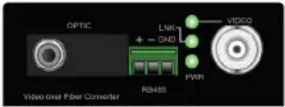
VF-101-T / VF-101-R VF-102-T / VF-102-R
VF-102SC-T / VF-102SC-R / VF-102S15-T / VF-102S15-R

VF-106-T / VF-106-R
2.1.1 Ports connection
| Video Connection | Connecting the video signal to or from the product through a 75Ω coax cable with BNC plug. |
| Async-data Connection | ■ Connect the output data port (eg. TX+ and TX-) of other control device to the RX+ and RX- of the RX■ Connect the input data port (eg. RX+ and RX-) of other under controlled device to the TX+ and TX- of the TX.■ GND in both TX and RX should be connected directly to user's equipment |
| Fiber Connection | Connect the fiber-optic cable pigtail (with FC/PC, SC/PC, WDM/PC or ST/PC optical connector) to the product's Fiber port. |
2.1.2 LED Indicators
The rich diagnostic LEDs on the front panel can provide the operating status of individual port and whole system. There are "POWER", "VIDEO", "LINK" 3 LEDs in the front panel of TX/RX. Each LED lightens means:
| LED Color Function | ||
| POWER Green | Lights to indicate that the Converter has power. | |
| VIDEO Green Lighted when video signal in. | ||
| LNK Green Lighted when laser in. | ||
2.2 Rear Panel
The rear panel of the converter indicates one DC jack, which accepts input power with 5V DC 2A.


Power Notice
- The device is a power-required device, meaning it will not work until it is powered. If your networks should be active all the time, please consider using a UPS (Uninterrupted Power Supply) for your device. This will prevent network data loss or network downtime.
- In some areas, installing a surge suppression device may also help protect your converter from being damaged by unregulated surges or current to the converter or the power adapter.
3 Install The Converter
This section describes how to install your VF-10x Media Converter and make connections to the converter. Please read the following topics and perform the procedures in the order presented. The hardware installation of the PLANET VF-10x Media Converter does not require software configuration. To install your VF-10x on a desktop or shelf, simply complete the following steps.
3.1 Limitation
The converter does not require any software configuration. Users can immediately use any feature of this product simply by attaching the cables and plugging in the power. There are some key limitations on the video over fiber converter. Please check the following items:
■ The device is used for point-to-point connection only (transmitter to receiver) and allows video and data to work on the same optical fiber patch cord. ■ The BNC connector supports 75-ohm cable. The distance will change depending on the quality of the coaxial cables.
3.2 Stand-alone Installation
To install a VF-10x-T / VF-10x-R stand-alone, on a desktop or shelf, simply complete the following steps:
Step 1: Turn off the power of the analog camera / monitor to which the VF-10x-T / VF-10x-R will be attached.
Step 2: VF-10x-T (Transmitter): Connect the coaxial cable from the analog camera to the Video BNC port of the VF-10x-T.
Step 3: Attach the FC single-mode fiber cable from the VF-10x-T to the VF-10x-R on the remote side.
Step 4: VF-10x-R (Receiver): Connect the coaxial cable from the monitor / DVR to the Video BNC port of the VF-10x-R.
Step 5: Connect the 5V DC power adapter to the VF-10x-T / VF-10x-R and verify that the Power LED lights up.
Step 6: Turn on the power of the analog camera / monitor; the VIDEO LED (Green) should light when all cables are attached.
![graph LR A["Speed Dome"] -->|Coax| B["VF-10X-T Transmitter"] B -->|Up to 20km| C["VF-10X-R Receiver"] C --> D["Coax"] D --> E["DVR / Monitor"] C --> F["Control Keyboard"] style A fill:#f9f,stroke:#333 style B fill:#ccf,stroke:#333 style C fill:#ccf,stroke:#333 style D fill:#cfc,stroke:#333 style E f…](/content/2026/06/1268219/images/cd95bfccf25dab0c874d78d633f7fcef56674d06a94b65d254e107aeabc44402.jpg)
Figure 3-1 VF-10x-T / VF-10x-R stand alone installation
3.3 Chassis Installation and Rack Mounting
To install the Video over fiber Converter in a 10-inch or 19-inch Converter Chassis with standard rack, follow the instructions described below.
Step 1: Place your Converter Chassis on a hard flat surface, with the front panel positioned towards your front side.
Step 2: Carefully slide in the module until it is fully and firmly fitted into the slot of the Converter Chassis.
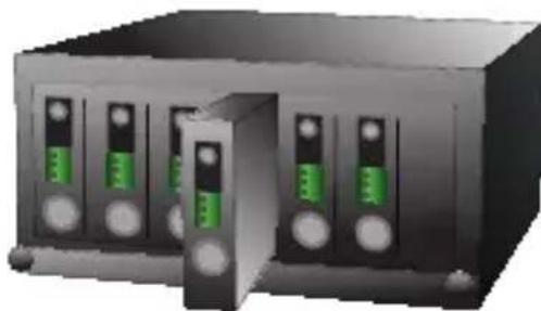
Figure 3-2: Insert a video over fiber converter into an available slot
Step 3: Attach a rack-mount bracket to each side of the Converter Chassis with supplied screws attached to the package.
Step 4: After the brackets are attached to the Converter Chassis, use suitable screws to securely attach the brackets to the rack.
Step 5: Proceed with the steps 4 and steps 5 of session 3.2 Stand-alone Installation to connect the video and fiber cabling and supply power to your Converter Chassis.
![graph TD A["Camera"] -->|Coax Video| B["VF-10X-T"] C["Camera"] -->|Coax Video| D["VF-10X-T"] E["Speed Dome"] -->|Coax Video OIOT| F["VF-10X-T"] G["Speed Dome"] -->|Coax Video OIOT| H["VF-10X-T"] B --> I["Media Converter Chassis"] D --> I F --> I H --> I I --> J["DVR / Monitor"] I --> K["Control Keyb…](/content/2026/06/1268219/images/9342145cba30efef0635c0d52a7666a8488b2790b81206bb20d71315e0b88fc8.jpg)
Figure 3-3 VF-10x-T / VF-10x-R media converter chassis installation
3.4 Optional - DIN-Rail mounting
There are two DIN-Rail holes on the left side of the VF-10x-T/VF-10x-R that allows the converter can be easily installed with DIN-Rail mounting. The PLANET optional DIN-Rail mounting Kit - RKE-DIN can be order separately. When need to replace the wall mount application with DIN-Rail application on the VF-10x-T / VF-10x-R, please refer to following figures to screw the DIN-Rail on the converter. To hang the VF-10x-T / VF-10x-R, follow the below steps:
Step 1: screw the DIN-Rail on the VF-10x-T / VF-10x-R.
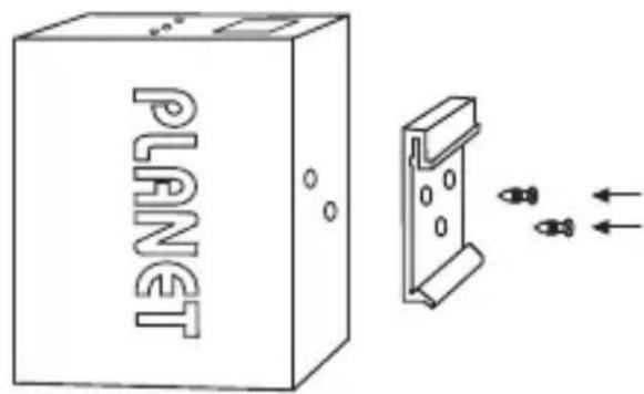
Step 2: Lightly press push the DIN-Rail into the track.

Step 3: Check that the DIN-Rail is tightly secured on the track.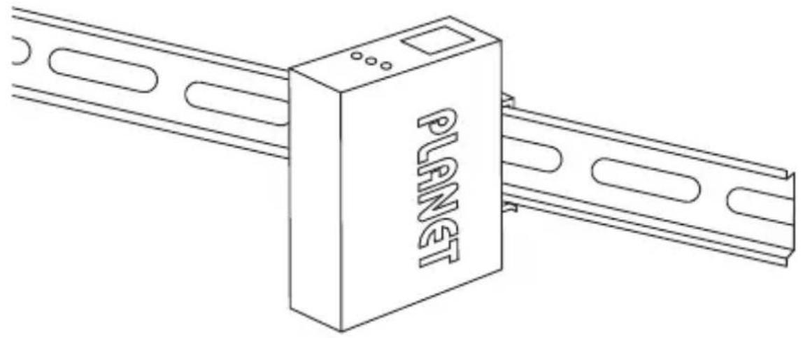

You must use the screws supplied with the mounting brackets. Damage caused to the parts by using incorrect screws would invalidate your warranty.
4. Power Information
The power jack of VF-10x-T / VF-10x-R has a 2.5mm central post and requires +5VDC power input. It will conform to the bundled AC-DC adapter and Planet's Media Converter Chassis. If you have issues with the power connection, please contact your local sales representative.
Please keep the AC-DC adapter as a spare part when your VF-10x is installed in a Media Converter Chassis.

2.5mm
DC Receptacle 2.5mm
+5V for each slot

The DC receptacle is 2.5mm wide, which conforms to and matches the Video over Fiber Converter's 2.5mm DC jack central post. Do not install any improper unit or model of the Video over Fiber Converter.

- OPTICAL FIBER TRANSMISSION SYSTEM
- VF-10X-KIT
- TRADEMARKS
- DISCLAIMER
- FCC WARNING
- CE MARK WARNING
- ENERGY SAVING NOTE OF THE DEVICE
- WEEE WARNING
- REVISION
- TABLE OF CONTENTS
- INTRODUCTION ...... 6
- HARDWARE DESCRIPTION ....11
- 3 INSTALL THE CONVERTER ....14
- POWER INFORMATION ....20
- INTRODUCTION
- 1.1 CHECK LIST
- 1.2 INTRODUCTION TO VIDEO OVER FIBER CONVERTER
- TYPICAL APPLICATIONS
- 1.3 KEY FEATURES
- 1.4 PRODUCT SPECIFICATION
- HARDWARE DESCRIPTION
- 2.1 FRONT PANEL
- 2.1.1 PORTS CONNECTION
- 2.1.2 LED INDICATORS
- 2.2 REAR PANEL
- 3 INSTALL THE CONVERTER
- 3.1 LIMITATION
- 3.2 STAND-ALONE INSTALLATION
- 3.3 CHASSIS INSTALLATION AND RACK MOUNTING
- 3.4 OPTIONAL - DIN-RAIL MOUNTING
- POWER INFORMATION
Brand : Planet
Model : VF-102SC-KIT
Category : Audio/video extension