
Lipari IX/LX/A - Range hood Turbo air - Free user manual and instructions
Find the device manual for free Lipari IX/LX/A Turbo air in PDF.


| Product type | Extracting or filtering hood (external evacuation or internal recycling version) |
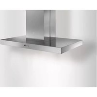
| Model | Lipari IX/LX/A |
| Brand | Turbo air |
| Power supply | 220-240 V / 50-60 Hz (check the rating plate) |
| Lighting power | 2 halogen lamps 12 V - 20 W max - G4 |
| Controls | 4 or 5 button keypad: light on/off, suction off, speed selection (1, 2, 3 or min, med, max) |
| Grease filter | Metal, cleanable monthly by hand or in dishwasher (gentle cycle) |
| Charcoal filter (recycling version) | Active, washable every 2 months (or non-washable, replace every 3-4 months) |
| Suction speeds | 3 speeds (minimum, medium, maximum) |
| Minimum safety distance | 50 cm above an electric hob, 65 cm above a gas or mixed hob |
| Exhaust duct diameter | Equal to the air outlet (diameter not specified, use recommended equivalent size) |
| Installation | Wall-mounted or island (ceiling); mounting kit supplied |
| Hood material | Stainless steel or lacquered (depending on aesthetic variant) |
| Maintenance | Monthly interior/exterior cleaning; do not use alcohol or abrasives |
| Weight | Approximately 15-25 kg (estimate for island hood) |
Frequently Asked Questions - Lipari IX/LX/A Turbo air
User questions about Lipari IX/LX/A Turbo air
0 question about this device. Answer the ones you know or ask your own.
Ask a new question about this device
Download the instructions for your Range hood in PDF format for free! Find your manual Lipari IX/LX/A - Turbo air and take your electronic device back in hand. On this page are published all the documents necessary for the use of your device. Lipari IX/LX/A by Turbo air.
USER MANUAL Lipari IX/LX/A Turbo air
EN Instruction on mounting and use


natural_image
Illustration of a hand holding a small blue object with a tool, no text or symbols present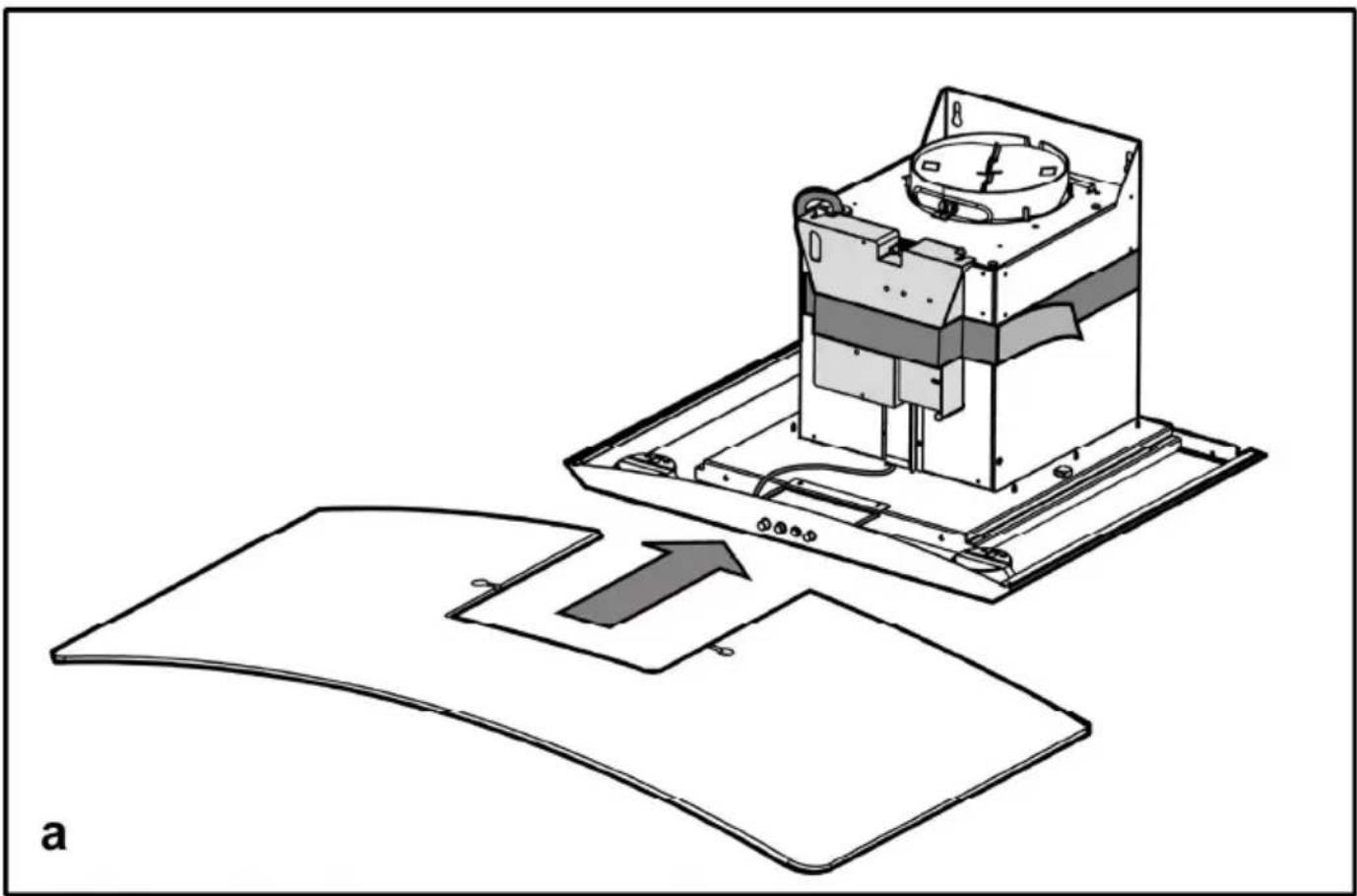
natural_image
Diagram of a device with internal components and an arrow indicating a process (no text or symbols present)

natural_image
Diagram of a mechanical device with directional arrows indicating motion or movement (no text or symbols)


natural_image
Architectural line drawing of a two-story brick structure with a sloped roof and vertical supports (no text or symbols)


EN - Instruction on mounting and use
Closely follow the instructions set out in this manual. All responsibility, for any eventual inconveniences, damages or fires caused by not complying with the instructions in this manual, is declined. The hood is conceived for the suction of cooking fumes and steam and is destined only for domestic use.
The hood can look different to that illustrated in the drawings in this booklet. The instructions for use, maintenance and installation, however, remain the same.
! It is important to conserve this booklet for consultation at any moment. In the case of sale, cession or move, make sure it is together with the product.
! Read the instructions carefully: there is important information about installation, use and safety.
! Do not carry out electrical or mechanical variations on the product or on the discharge conduits.
! Before proceeding with the installation of the appliance verify that there are no damaged all components. Otherwise contact your dealer and do not proceed with the installation.
Note: the elements marked with the symbol “(*)” are optional accessories supplied only with some models or elements to purchase, not supplied.

Caution
WARNING! Do not connect the appliance to the mains until the installation is fully complete.
Before any cleaning or maintenance operation, disconnect hood from the mains by removing the plug or disconnecting the mains electrical supply.
Always wear work gloves for all installation and maintenance operations.
The appliance is not intended for use by children or persons with impaired physical, sensorial or mental faculties, or if lacking in experience or knowledge, unless they are under supervision or have been trained in the use of the appliance by a person responsible for their safety.
This appliance is designed to be operated by adults, children should be monitored to ensure that they do not play with the appliance.
This appliance is designed to be operated by adults. Children should not be allowed to tamper with the controls or play with the appliance.
Never use the hood without effectively mounted grating!
The hood must NEVER be used as a support surface unless specifically indicated.
The premises where the appliance is installed must be sufficiently ventilated, when the kitchen hood is used together with other gas combustion devices or other fuels.
The ducting system for this appliance must not be connected to any existing ventilation system which is being used for any other purpose such as discharging exhaust fumes from appliances burning gas or other fuels.
The flaming of foods beneath the hood itself is severely prohibited.
The use of exposed flames is detrimental to the filters and may cause a fire risk, and must therefore be avoided in all circumstances.
Any frying must be done with care in order to make sure that the oil does not overheat and ignite.
Accessible parts of the hood may become hot when used with cooking appliance.
With regards to the technical and safety measures to be adopted for fume discharging it is important to closely follow the regulations provided by the local authorities.
The hood must be regularly cleaned on both the inside and outside (AT LEAST ONCE A MONTH).
This must be completed in accordance with the maintenance instructions provided in this manual). Failure to follow the instructions provided in this user guide regarding the cleaning of the hood and filters will lead to the risk of fires.
Do not use or leave the hood without the lamp correctly mounted due to the possible risk of electric shocks.
We will not accept any responsibility for any faults, damage or fires caused to the appliance as a result of the non-observance of the instructions included in this manual.
This appliance is marked according to the European directive 2002/96/EC on Waste Electrical and Electronic Equipment (WEEE). By ensuring this product is disposed of correctly, you will help prevent potential negative consequences for the environment and human health, which could otherwise be caused by inappropriate waste handling of this product.
The symbol ■ on the product, or on the documents accompanying the product, indicates that this appliance may not be treated as household waste. Instead it should be taken to the appropriate collection point for the recycling of electrical and electronic equipment. Disposal must be carried out in accordance with local environmental regulations for waste disposal.
For further detailed information regarding the process, collection and recycling of this product, please contact the appropriate department of your local authorities or the local department for household waste or the shop where you purchased this product.
Appliance designed, tested and manufactured according to:
- Safety: EN/IEC 60335-1; EN/IEC 60335-2-31, EN/IEC 62233.
• Performance: EN/IEC 61591; ISO 5167-1; ISO 5167-3; ISO 5168; EN/IEC 60704-1; EN/IEC 60704-2-13; ISO 3741; EN 50564; IEC 62301.
- EMC: EN 55014-1; CISPR 14-1; EN 55014-2; CISPR 14-2; EN/IEC 61000-3-2; EN/IEC 61000-3-3. Suggestions for a correct use in order to reduce the environmental impact: Switch ON the hood at minimum speed when you start cooking and kept it running for few minutes after cooking is finished. Increase the speed only in case of large amount of smoke and vapour and use boost speed(s) only in extreme situations. Replace the charcoal filter(s) when necessary to maintain a good odour reduction efficiency. Clean the grease
filter(s) when necessary to maintain a good grease filter efficiency. Use the maximum diameter of the ducting system indicated in this manual to optimize efficiency and minimize noise.
Use
The hood is designed to be used either for exhausting or filter version.
Ducting version
The hood is equipped with a top air outlet B for discharge of fumes to the outside (exhaust pipe and pipe fixing clamps not provided). Connect the hood and discharge holes on the walls with a diameter equivalent to the air outlet (connection flange). Using the tubes and discharge holes on walls with smaller dimensions will cause a diminution of the suction performance and a drastic increase in noise.
Any responsibility in the matter is therefore declined.
Attention! If the hood is supplied with carbon filter, then it must be removed.
Filter version
Should it not be possible to discharge cooking fumes and vapour to the outside, the hood can be used in the filter version, fitting an activated carbon filter and the deflector F on the support (bracket) G, fumes and vapours are recycled through the top grille H by means of an exhaust pipe connected to the top air outlet B and the connection ring mounted on the deflector F (exhaust pipe and pipe fixing clamps not provided).
Attention! If the hood is not supplied with carbon filter, then it must be ordered and mounted.
The models with no suction motor only operate in ducting mode, and must be connected to an external suction device (not supplied).
The connecting instructions are supplied with the peripheral suction unit.
Installation
The minimum distance between the supporting surface for the cooking equipment on the hob and the lowest part of the range hood must be not less than 50cm from electric cookers and 65cm from gas or mixed cookers.
If the instructions for installation for the gas hob specify a greater distance, this must be adhered to.

Electrical connection
The mains power supply must correspond to the rating indicated on the plate situated inside the hood. If provided with a plug connect the hood to a socket in compliance with current regulations and positioned in an accessible area, after installation. If it not fitted with a plug (direct mains connection) or if the plug is not located in an accessible area, after installation, apply a double pole switch in accordance with standards which assures the complete disconnection of the mains under conditions relating to over-current category III, in accordance with installation instructions.
Warning! Before re-connecting the hood circuit to the mains supply and checking the efficient function, always check that the mains cable is correctly assembled.
Mounting
The hood is supplied in two versions: model for installation to the wall and model for installation to the ceiling.
Before beginning installation:
- Check that the product purchased is of a suitable size for the chosen installation area.
- Remove the charcoal (*) filter/s if supplied (see also relative paragraph). This/these is/are to be mounted only if you want to use the hood in the filtering version.
- Check (for transport reasons) that there is no other supplied material inside the hood (e.g. packets with screws (*), guarantees (*), etc.), eventually removing them and keeping them.
- If possible, disconnect and move freestanding or slide-in range from cabinet opening to provide easier access to rear wall/ceiling. Otherwise put a thick, protective covering over countertop, cooktop or range to protect from damage and debris. Select a flat surface for assembling the unit. Cover that surface with a protective covering and place all canopy hood parts and hardware in it.
- In addition check whether near the installation area of the hood (in the area accessible also with the hood mounted) an electric socket is available and it is possible to connect a fumes discharge device to the outside (only suction version).
- Carry out all the masonry work necessary (e.g. installation of an electric socket and/or a hole for the passage of the discharge tube).
Expansion wall plugs are provided to secure the hood to most types of walls/ceilings. However, a qualified technician must verify suitability of the materials in accordance with the type of wall/ceiling. The wall/ceiling must be strong enough to take the weight of the hood. Do not tile, grout or silicone this appliance to the wall. Surface mounting only.
Installation ceiling model (Island)
Fig. 5-6-7
-
Adjust the extension of the support structure of the hood. The final height of the hood depends on this adjustment.
Note: In some cases the upper section of the trellis is fixed to the lower section with 1 or more screws. Check and remove them temporarily to allow the adjustment of the support structure. -
Fix the two sections with a total of 16 screws (4 per corner).
Apply 1 or 2 brackets as reinforcement for extensions greater than the minimum (on the basis of what is envisaged as equipment).
Note: 1 bracket can already be fixed to the trellis temporarily with 2 screws during transport. Move it into the desired position or complete fixing it with 6 additional screws, as follows:
a. Slightly stretch the brackets to be fixed in order to be able to apply them outside the structure.
b. Position the reinforcement bracket immediately above
the fixing point of the two sections of the structure and fix with a total of 8 screws (2 per corner).
Fix the second reinforcement bracket, if supplied, in a position midway between the first reinforcement bracket and the upper side of the trellis and fix with 8 screws (2 per corner).
Note: check that there is no obstacle to an easy fixing of the discharge tube (aspiration version) or the deflector (filtering version) in positioning the reinforcement bracket(s).
-
Hook the hood to the trellis and make sure that it is perfectly hooked up. Screw the 16 screws up (4 per corner) tightly to hook the hood to the trellis.
-
Apply the perforation diagram of the cooking top to the ceiling vertically (the centre of the diagram must correspond to the centre of the cooking top and the sides must be parallel to the sides of the cooking top – the side of the diagram with the word FRONT corresponds to the control panel side). Prepare the electrical connection.
-
Make holes as indicated (6 holes for 6 wall dowels - 4 dowels for hooking), and screw 4 screws into the external holes, leaving a space of about 1cm between the head of the screws and the ceiling.
-
Hook the trellis to the ceiling with 4 screws, see operation 4).
-
Screw the 4 screws up tightly.
-
Introduce and screw another 2 screws tightly into the holes for fixing the safety elements remaining free.
-
Introduce a discharge tube inside the trellis and connect to the connecting ring of the motor space (discharge tube and bands not supplied). The discharge tube must be long enough to reach the exterior (aspiration version) or the deflector (filtering version).
-
Only for filtering version: mount deflector F onto the trellis and fix it with 4 screws to the apposite bracket and finally connect the discharge tube to the connection ring placed on the deflector.
-
Connect the electricity to the domestic power. Power must be supplied only after the installation has been completed.
-
Put the nuts equipped with fixing hooks inside the sections of the upper and lower flues in correspondence with the rectangular slots. A total of 14 nuts should be mounted.
-
Couple the two upper sections of the flue to cover the trellis so that one of the slits present on the sections is placed on the same side of the command panel and the other on the opposite side.
Screw the two sections up with 8 screws (4 per side – also see the plan diagram for coupling the two sections).
-
Fix the upper flue set to the trellis near the ceiling with two screws (one per side).
-
Couple the two lower sections of the flue to cover the trellis using 6 screws (3 per side - also see the plan diagram for coupling the two sections).
-
Insert the lower section of the flue into the apposite housing to cover the motor space and the electrical connection box completely and fix with two screws from
inside the hood.
- Apply the 2 tabs (supplied) to cover the fixing points of the sections of the lower flue (ATTENTION! THE TABS FOR THE LOWER FLUE ARE RECOGNISABLE BECAUSE THEY ARE NARROWER AND LESS DEEP).
The larger and deeper tabs are those to use for the upper flue and are to be cut to measure.
- Supply the electrical power again acting on the central electrical panel and check the correct functioning of the hood.
Installation wall model
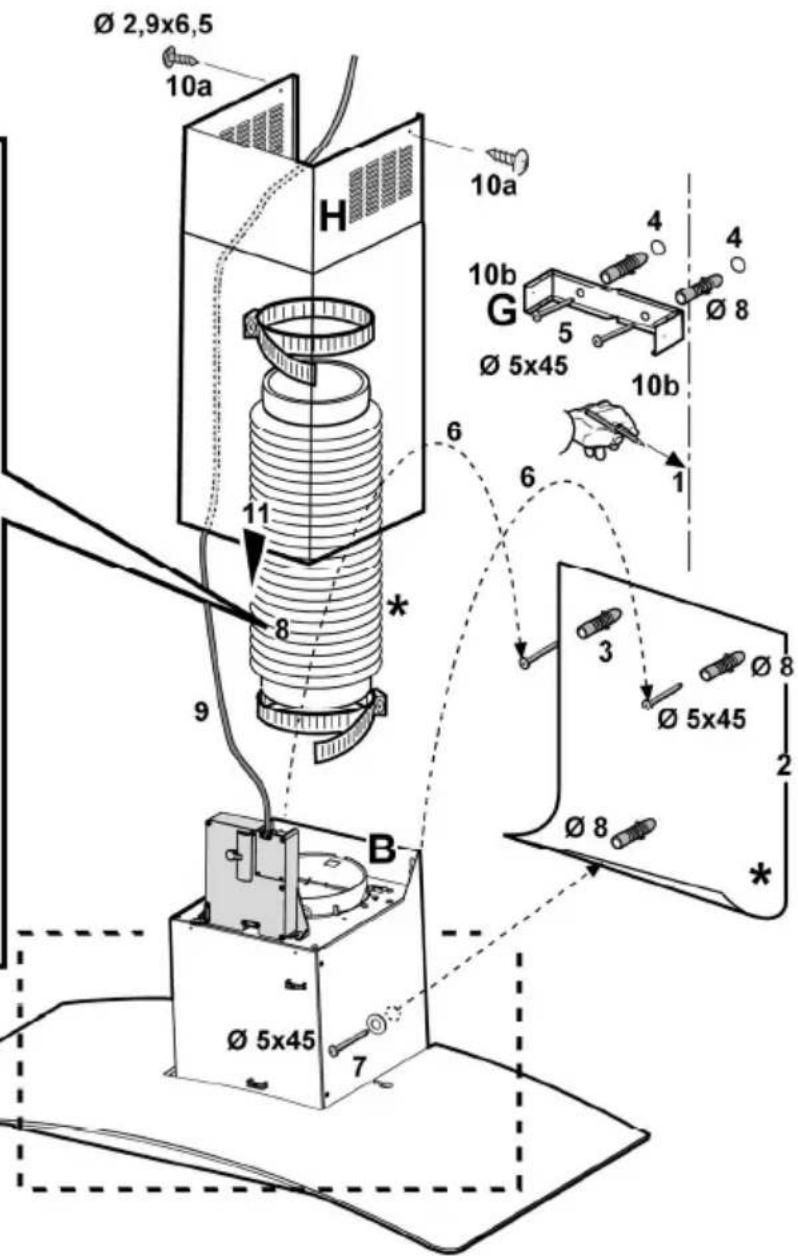
When the vapour catcher is disassembled, it must be fixed as shown in Fig. a,b.
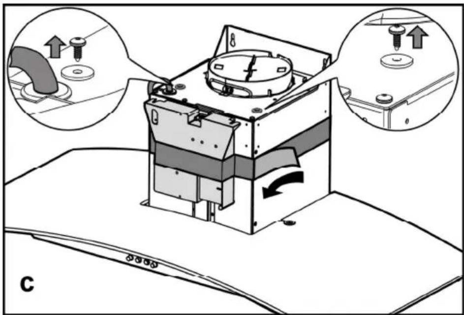
The electric connection box must be assembled as shown in Fig. c,d,e.
Fig. 9
- Drawing a line on the wall with a pencil up to the ceiling, corresponding to the centre line, will make the installation operations easier.
- Apply the perforation diagram to the wall: the vertical centre line printed on the perforation diagram should correspond to the centre line drawn on the wall. In addition, the lower edge of the perforation diagram corresponds to the lower edge of the hood.
- Make holes as indicated on the template, insert the wall dowels and screw 2 screws into the upper holes, leaving a space of about 1 cm between the head of the screw and the wall.
Note: Always make the holes indicated on the template.
The upper 2 are for hooking the hood up while the lower holes (generally 1 central or more lateral) are for the definitive and safety fixing.
- Apply flues support bracket „G“ to the wall touching the ceiling. Use the flues support bracket as a perforation diagram (the small slot in the support must coincide with the line previously drawn on the wall, if present), and mark two holes with a pencil. Make the holes and insert 2 dowels.
- Fix the flues support bracket to the wall with 2 screws.
- Hang the hood to the two upper screws (see installation phase 3).
- Introduce and screw the screws (and washer(s)) up into the hole(s) for the definitive fixing (COMPULSORY!!). Then, having checked the setting of the hood, TIGHTEN ALL THE upper and lower SCREWS.
Note: the lower fixing points are visible removing the fats filters and they are at the sides and/or at the centre of the hood (after having removed the frame of the carbon filter, if present, in the latter case).
In any case, we recommend using the lateral holes, when available, to increase the stability of the hood.
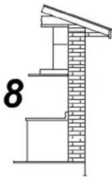
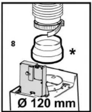
- Connect a tube (tube and bands for fixing not supplied, to be purchased) for discharging the fumes to the connection ring placed over the aspiration motor unit.
The other end of the tube should be connected to a device for expelling fumes on the outside of the hood in the aspiration version. If you want to use the filtering
version, fix deflector F to flues support bracket G and connect the other end of the tube to the connection ring placed on deflector F.
9. Connect the electricity.
-
Apply the flues and fix them above with 2 screws (10a) to flues support bracket „G“ (10b).
-
Slide the lower section of the flue down to cover the aspiration set until inserting it completely into the apposite housing over the hood. Remount the carbon filter frame and the fat/s filter/s and check the perfect functioning of the hood.
Additional Installation Specifications:
Use only the fixing screws supplied with the product for installation or, if not supplied, purchase the correct screws type.
Use the correct length for the screws which are identified in the Installation Guide.
In case of doubt, consult an authorised service assistance centre or similar qualified person.
WARNING! Failure to install the screws or fixing device in accordance with these instructions may result in electrical hazards.
Description of the hood - Fig. 1
- Control panel
- Grease filter
- Grease filter release handle
- Halogen lamp
- Vapour catcher
- Telescopic chimney
- Air outlet (used for filter version only)
Operation
Use the high suction speed in cases of concentrated kitchen vapours. It is recommended that the cooker hood suction is switched on for 5 minutes prior to cooking and to leave in operation during cooking and for another 15 minutes approximately after terminating cooking.
Model with 4 push-buttons control panel

a. ON/OFF light switch
b. Speed 1/OFF switch
c. 2-speed selection
d. 3-speed selection
Model with 5-key keyboard

a. on/off light switch
b. off aspiration switch
c. minimum power selection aspiration switch
d. medium power selection aspiration switch
e. maximum power selection aspiration switch
Maintenance
ATTENTION! Before performing any maintenance operation, isolate the hood from the electrical supply by switching off at the connector and removing the connector fuse.
Or if the appliance has been connected through a plug and socket, then the plug must be removed from the socket.
Cleaning
The cooker hood should be cleaned regularly (at least with the same frequency with which you carry out maintenance of the fat filters) internally and externally. Clean using the cloth dampened with neutral liquid detergent. Do not use abrasive products. DO NOT USE ALCOHOL!
WARNING: Failure to carry out the basic cleaning recommendations of the cooker hood and replacement of the
filters may cause fire risks.
Therefore, we recommend observing these instructions.
The manufacturer declines all responsibility for any damage to the motor or any fire damage linked to inappropriate maintenance or failure to observe the above safety recommendations.
Grease filter
Traps cooking grease particles.
The grease filter must be cleaned once a month using non aggressive detergents, either by hand or in the dishwasher, which must be set to a low temperature and a short cycle. When washed in a dishwasher, the grease filter may discolour slightly, but this does not affect its filtering capacity.
To remove the grease filter, pull the spring release handle.
Fig. 2
Charcoal filter (filter version only)
Fig. 3
It absorbs unpleasant odours caused by cooking.
The charcoal filter can be washed once every two months using hot water and a suitable detergent, or in a dishwasher at 65^ C (if the dishwasher is used, select the full cycle function and leave dishes out).
Eliminate excess water without damaging the filter, then remove the mattress located inside the plastic frame and put it in the oven for 10 minutes at 100^ C to dry completely. Replace the mattress every 3 years and when the cloth is damaged.
Remove the filter holder frame by turning the knobs (g) 90° that affix the chimney to the cooker hood.
Insert the pad (i) of activated carbon into the frame (h) and fit the whole back into its housing (j).
It is possible to use a traditional carbon filter, neither washable nor regenerable, to be replaced every 3 - 4 months.
The filter holder frame of the carbon filter is welded together; the eventual frame supplied with the hood is not, therefore, to be used.
Insert it into its housing and fix it turning the 2 plastic knobs.
Replacing lamps
Disconnect the appliance from the electricity.
Warning! Prior to touching the light bulbs ensure they are cooled down.
Replace the old light bulb with the one of the same type as specified in the feature label or near the light lamp on the hood. Fig. 4
-
Using a flat head screwdriver or equivalent tool, carefully pry loose the light cover.
-
Remove the damaged light and replace with a new 12 Volt, 20 Watt (Maximum) halogen light made for a G-4 base SUITABLE FOR USE IN OPEN LUMINAIRES. Follow package directions and do not touch new light with bare hands.
-
Reinstall the light cover. (it will snap shut).
If the lights do not work, make sure that the lamps are fitted properly into their housings before you call for technical assistance.
odstranite in shranite.


- EN - Instruction on mounting and use
- Caution
- Use
- Ducting version
- Filter version
- Installation
- Electrical connection
- Mounting
- Before beginning installation:
- Installation ceiling model (Island)
- Fig. 5-6-7
- Installation wall model
- Fig. 9
- Connect the electricity.
- Additional Installation Specifications:
- Description of the hood - Fig. 1
- Operation
- Model with 4 push-buttons control panel
- Model with 5-key keyboard
- Maintenance
- Cleaning
- Grease filter
- Traps cooking grease particles.
- Charcoal filter (filter version only)
- It absorbs unpleasant odours caused by cooking.
- Replacing lamps
Brand : Turbo air
Model : Lipari IX/LX/A
Category : Range hood