
WR 11-2 B - Boiler Junkers - Free user manual and instructions
Find the device manual for free WR 11-2 B Junkers in PDF.


| Product Type | Gas-fired instantaneous water heater (boiler) |
| Brand | Junkers |
| Model | WR 11-2 B |
| Gas Type | Natural gas (G20) or propane (G31) |
| Nominal Heat Input | 11 kW (9,400 kcal/h) |
| Hot Water Flow Rate (Δt=25°C) | 6.3 L/min |
| Hot Water Flow Rate (Δt=35°C) | 4.5 L/min |
| Ignition | Piezoelectric |
| Flue Type | Room-sealed (B23P) or open flue (B11BS) |
| Power Supply | None (piezo ignition, no electric connection required) |
| Safety Devices | Flame failure device, water flow sensor, overheat protection |
| Water Connection | G 1/2" BSP |
| Gas Connection | G 1/2" BSP |
| Dimensions (H x W x D) | 580 x 310 x 220 mm |
| Weight | 10 kg |
| Minimum Water Pressure | 0.3 bar |
| Maximum Water Pressure | 10 bar |
| Temperature Adjustment | 30°C to 60°C |
| Maintenance | Annual descaling and burner cleaning recommended |
| Spare Parts Available | Thermocouple, gas valve, burner, water flow sensor |
| Repairability | Modular design; common spare parts available |
| CE Marking | Yes |
Frequently Asked Questions - WR 11-2 B Junkers
User questions about WR 11-2 B Junkers
0 question about this device. Answer the ones you know or ask your own.
Ask a new question about this device
Download the instructions for your Boiler in PDF format for free! Find your manual WR 11-2 B - Junkers and take your electronic device back in hand. On this page are published all the documents necessary for the use of your device. WR 11-2 B by Junkers.
USER MANUAL WR 11-2 B Junkers
Installation Manual and Operating Instructions
Gas Heaters
miniMAXX

WR 11 -2 .B..
WR 14 -2 .B..
WR 18 -2 .B..

Read installation manual prior to installation of this unit!
Read user manual before putting this unit in operation!

Observe the warnings in the manuals!
The installation room must fulfill the ventilation requirements!

Installation by an authorised person only!
Table of contents
1 Warnings and symbols 3
1.1 Safety Instructions 3
1.2 Key to symbols 3
2 Information about the heater 4
2.1 Category, type and approval no. 4
2.2 Technical identification code 4
2.3 Package contents 4
2.4 Description of the heater 4
2.5 Special accessories 4
2.6 Dimensions 5
2.7 Functional diagram of the heater 6
2.8 Electrical diagram 7
2.9 Function 7
2.10 Technical characteristics 8
3 Regulations 9
4 Installation 10
4.1 Important information 10
4.2 Selection of the place of installation 10
4.3 Heater mounting 11
4.4 Water connection 11
4.5 Gas connection 11
4.6 Startup 11
5 Operating instructions 12
5.1 Batteries 12
5.2 Before starting up the heater 12
5.3 Turning the heater on and off 12
5.4 Power adjustment 12
5.5 Temperature/flow adjustment 13
5.6 Purge the appliance 13
6 Adjustments 14
6.1 Factory settings 14
6.2 Pressure adjustment 14
6.3 Converting to a different gas type 14
7 Maintenance 15
7.1 Periodic maintenance tasks 15
7.2 Startup after maintenance work 15
7.3 Flue gas safety device 15
8 Problems 17
8.1 Problem/cause/solution 17
9 Environmental protection 18
1 Warnings and symbols
1.1 Safety Instructions
If there is a smell of gas:
▶ Close the gas valve.
▶ Open windows.
- Do not operate any electrical appliances or switches (on/off).
▶ Extinguish any naked flames.
▶ Phone the gas company or an authorized technician from a safe distance.
If there is a smell of burnt gases:
▶ Disconnect the appliance.
▶ Open doors and windows.
▶ Inform an installation company.
Fitting, modifications
The fitting and modification of the installation of the appliance must be carried out only by an authorized technician.
▶ The pipes carrying burnt gases must not be modified.
▶ Do not close or reduce air circulation holes.
Maintenance
▶ We recommend to have the system regularly serviced in order to ensure that it functions reliably and safely.
▶ The installer is responsible for the safety and environmental compatibility of the installation.
▶ The appliance should be serviced annually.
▶ Only original spare parts must be used.
Explosive and inflammable materials
▶ Inflammable materials (paper, solvents, ink, etc.) should not be stored near the appliance.
Combustion air and ambient air
▶ To avoid corrosion, combustion air and ambient air should be free of aggressive substances (for example halogenated hydrocarbons containing chlorine and fluoride composites).
Client information
- Inform the client about the function and operation of the appliance.
This appliance is not intended for use by persons (including children) with reduced physical sensory or mental capabilities, or lack of experience and knowledge, unless they have been given supervision or instruction concerning use of the appliance by a person responsible for their safety.
Children should be supervised to ensure they do not play with the appliance.
▶ Caution clients against performing modifications or repairs themselves.
1.2 Key to symbols

The safety instructions in the text appear on a grey ground and are signaled in the margin by a triangle containing an exclamation mark.
The different types of warnings serve to indicate the degree of risk, if the damage reduction precautions are not followed.
- Caution is used to indicate the risk of light material damage.
- Warning is used to indicate the risk of light personal damage or more serious material damage
- Danger is used to indicate the risk of serious personal damage that might in some circumstances be fatal

Indications in the text are identified by the symbol in the margin.
The beginning and end of the text are indicated by a horizontal line.
The indications include important information that does not necessarily implicate risk to people or the appliance itself.
2 Information about the heater
2.1 Category, type and approval no.

| Model WR 11/14/18 -2 B... | |
| Category | II2H3+ |
| Type | B11BS |
Tab. 1
2.2 Technical identification code
| W | R | 11 | -2 | B | 23 | S... |
| 31 | ||||||
| W | R | 14 | -2 | B | 23 | S... |
| 31 | ||||||
| WR | 18 | -2 | B | 23 | S... | |
| 31 |
Tab. 2
W Water gas heater
R Proportional power adjustment
11 Capacity (l/min)
-2 Version 2
B Electronic ignition powered by 1.5 V batteries
23 Appliance adjusted for natural gas
31 Appliance adjusted for GPL
S... Country code
2.3 Package contents
- Gas heater
- Attachment elements
- Connection elements
- Heater documentation
- Two 1.5 V batteries type R
• Rubber holders (LPG heaters)
2.4 Description of the heater
Operating convenience, as the heater is ready to operate by simply pressing a switch.
- Heater for wall-mounting
- Ignition by electronic device triggered when the water valve opens
- Great savings in comparison with conventional heaters, due to the possibility of power adjustment and no permanent pilot flame
• Natural gas/LPG burner
- Semi-permanent pilot burner which only functions during the period between the opening of the water valve and the ignition of the main burner
- Combustion chamber without tin/lead covering
• Water valve in fibreglass-reinforced polyamide, 100% recyclable
- Automatic adjustment of the water flow by means of a device which permits a constant flow to be maintained in spite of variable pressure supplies
- Gas flow adjustment proportional to the water flow to maintain a constant high temperature.
- Safety devices:
– Ionisation probe to check for accidental extinction of the burner flame
- Flue gas safety device which turns off the heater in case of inadequate combusted gas evacuation conditions
- Temperature limiter which prevents overheating of the combustion chamber
2.5 Special accessories
- Conversion kit from natural gas to butane/propane and vice-versa
2.6 Dimensions
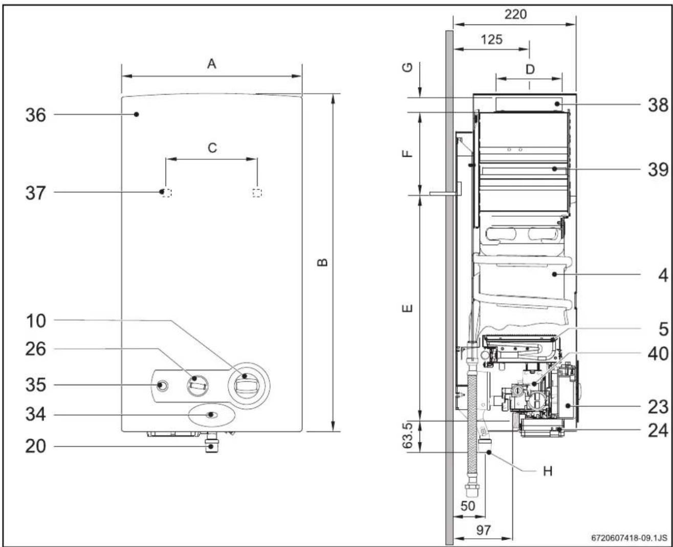
Fig. 1
4 Combustion chamber
5 Burner
10 Temperature/volume selector
20 Gas connection
23 Ignition unit
24 Battery compartment
26 Power selector
34 LED - Burner status check
35 Switch / LED - Battery status check
36 Front
37 Opening for mounting on the wall
38 Connection collar to the combustion gases pipe
39 Flue with non-return device
40 Gas valve
| Dimensions(mm) | A | B | C | D | E | F | G | H (Ø) | |
| Natural gas | LPG | ||||||||
| WR11B 310 | 580 228 | 112,5 463 | 60 25 | 3/4" 1/2" | |||||
| WR14B 350 | 655 228 | 132,5 510 | 95 30 | 3/4" 1/2" | |||||
| WR18B 425 | 655 334 | 132,5 540 | 65 30 | 3/4" 1/2" | |||||
Tab. 3 Dimensions
2.7 Functional diagram of the heater
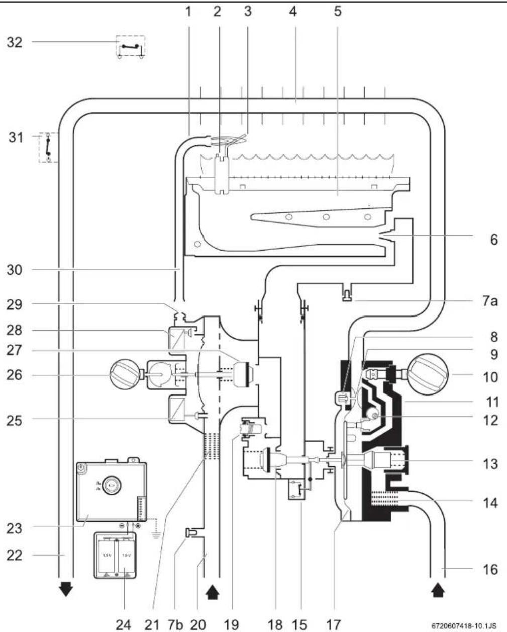
Fig. 2 Functional diagram
1 Pilot burner
2 Spark plug
3 Ionisation probe
4 Combustion chamber
5 Main burner
6 Injector
7a Screw for measurement of pressure in burner
7b Screw for measurement of input pressure
8 Slow ignition valve
9 Venturi
10 Temperature/volume selector
11 Water valve
12 Command cone
13 Water flow regulator
14 Water filter
15 Micro-switch
16 Cold water pipe
17 Diaphragm
18 Main gas valve
19 Maximum gas adjusting screw
20 Gas supply pipe
21 Gas filter
22 Hot water pipe
23 Ignition unit
24 Battery compartment
25 Servo valve
26 Power selector
27 Gas valve
28 Pilot valve
29 Pilot injector
30 Pilot gas pipe
31 Temperature limiter
32 Flue gas safety device
2.8 Electrical diagram
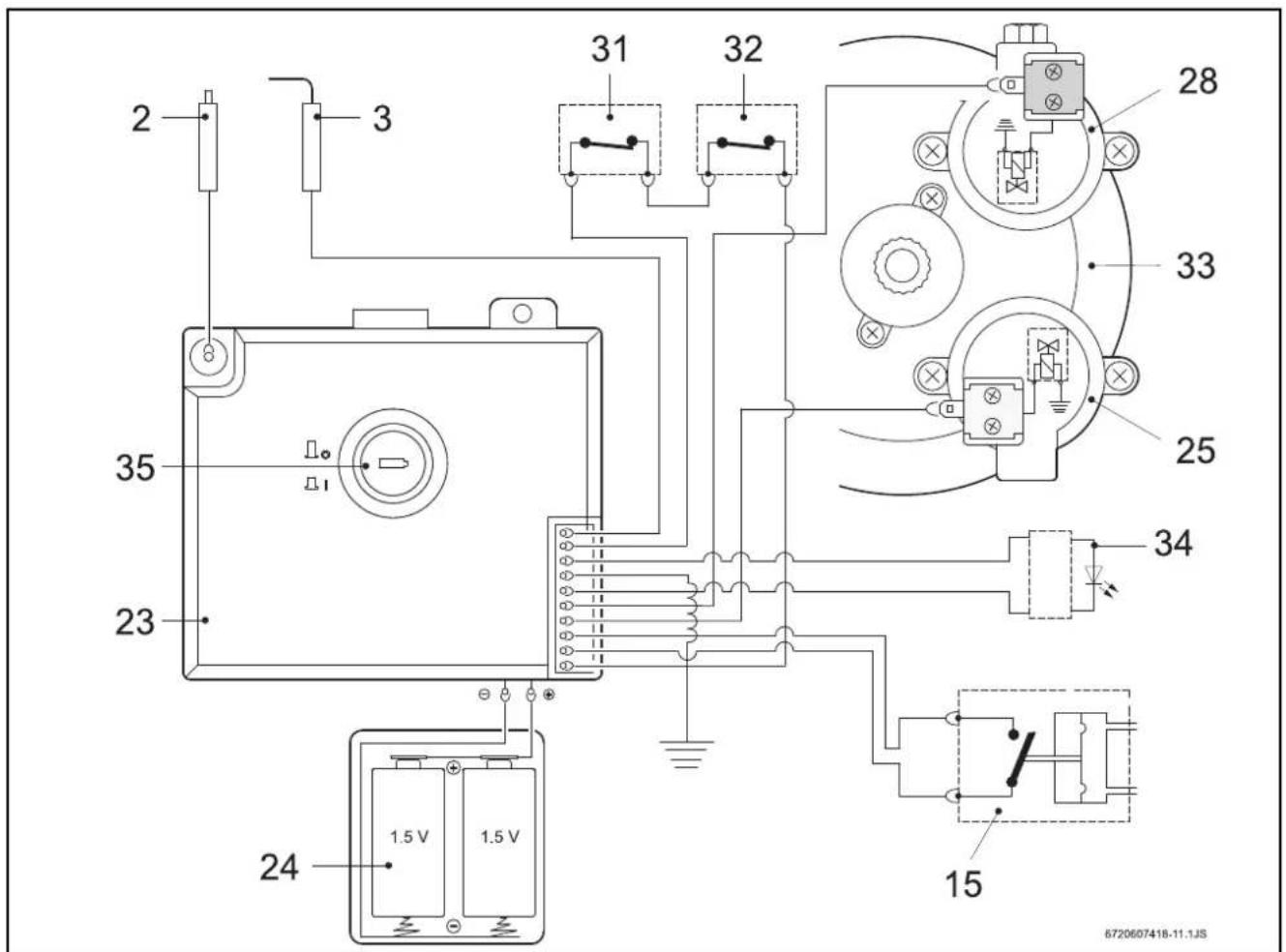
Fig. 3 Electrical diagram
2 Spark plug
3 Ionisation probe
15 Micro-switch
23 Ignition unit
24 Battery compartment
25 Servo valve (normally open)
2.9 Function
This gas heater is equipped with automatic electronic ignition which simplifies its operation.
▶ To do so, just turn on the switch (Fig. 8).
After this procedure, automatic ignition occurs whenever a hot water tap is opened. First, the pilot burner is lit and approximately four seconds afterwards the main burner. The pilot burner flame is then extinguished after a short period of time.
This is a way of saving a great amount of energy as the pilot burner only operates for the minimum necessary time to ignite the main burner, in contrast to conventional systems which operate permanently.
28 Pilot valve (normally closed)
31 Temperature limiter
32 Flue gas safety device
33 Diaphragm valve
34 LED - Burner status check
35 Switch / LED - Battery status check

Air in the gas supply pipe when the heater is started up may cause ignition to fail.
If thishappens:
▶ Close and open the hot water tap to repeat the ignition process until all the air has been purged.
2.10 Technical characteristics
| Technical characteristics | Symbol | Units | WR11 | WR14 | WR18 |
| Power and flow | |||||
| Nominal useful power | Pn | kW | 19,2 | 23,6 | 30,5 |
| Minimum useful power | Pmin | kW | 7 | 7 | 9 |
| Useful power (adjustment range) | kW 7 - 19,2 | 7 - 23,6 7 - 30,5 | |||
| Nominal thermal flow Qn | kW 21,8 | 27 34,5 | |||
| Minimum thermal flow Qmin | kW 8,1 | 8,1 10,3 | |||
| Gas data* | |||||
| Supply pressure | |||||
| Natural gas H G20 | mbar | 20 | 20 | 20 | |
| LPG (butane/propane) | G30/G31 | mbar | 30/37 | 30/37 | 30/37 |
| Consumption | |||||
| Natural gas H G20 | m3/h | 2,3 | 2,9 | 3,7 | |
| LPG (butane/propane) | G30/G31 | kg/h | 1,7 | 2,2 2,75 | |
| Number of injectors | 12 | 14 | 18 | ||
| Water data | |||||
| Maximum permissible pressure** | pw | bar | 12 | 12 | 12 |
| Temperature selector in fully clockwise position | |||||
| Temperature rise | °C | 50 | 50 | 50 | |
| Flow range | l/min 2 - 5,5 | 2 - 7 | 2 - 8,8 | ||
| Minimum operating pressure | pwmin | bar 0,1 | 0,1 | 0,2 | |
| Minimum pressure for maximum flow | bar | 0,25 | 0,35 0,5 | ||
| Temperature selector in fully anti-clockwise position | |||||
| Temperature rise | °C | 25 | 25 | 25 | |
| Flow range | l/min | 4 - 11 | 4 - 14 | 4 - 17,6 | |
| Minimum operating pressure | bar 0,2 | 0,2 | 0,2 | ||
| Minimum pressure for maximum flow | bar 0,6 | 1 | 1,3 | ||
| Combustion products*** | |||||
| Minimum low pressure | mbar | 0,015 | 0,015 | 0,015 | |
| Flow | g/s | 13 | 17 | 22 | |
| Temperature | °C 160 | 170 180 | |||
Tab. 4
* Hi 15 °C - 1013 mbar - dry: Natural gas 34.2 MJ/m³ (9.5 kWh/m³)
LPG: Butane 45.72 MJ/kg (12.7 kWh/kg) - Propane 46.44 MJ/kg (12.9 kWh/kg)
** Considering the water dilution effect this value must not be exceeded.
*** For nominal calorific power
3 Regulations
Any local by-laws and regulations pertaining to installation and use of gas-heated appliances must be observed. Please refer to the laws that should be attended in your country.
4 Installation

Danger: Explosion
▶ Always turn off the gas cock before carrying out any work on components which carry gas.

The gas installation, the connection of exhaust/supply pipes as well as the initial startup are to be performed exclusively by authorised gas fitters.

The heater can only be used in the countries indicated on the rating plate.
4.1 Important information
▶ Before installing, call the gas company and check the standard relating to gas heaters and ventilation requirements for rooms.
▶ Install a gas cut-off valve as close as possible to the heater.
▶ After finishing the gas system, the pipes must be thoroughly cleaned and leak-tested; to avoid damaging the gas valve by excess pressure, this test must be performed with the gas valve of the heater closed.
▶ Check if the heater corresponds to the type of gas provided.
▶ Check if the flow and pressure through the installed reducer are appropriate for the consumption of the heater (see technical data in the table 4).
4.2 Selection of the place of installation
Requirements regarding the place of installation
- Do not install the heater in rooms with a volume of less than 8m3 (not including the volume of the furniture providing this does not exceed 2m3 .
- Comply with the specific instructions for each country.
- Assemble the gas heater in a well-ventilated location where it will not be exposed to temperatures below zero and in a place where there is an evacuation pipe for combustion gases.
- The gas heater must not be installed over a heat source.
-
To avoid corrosion, the combustion air must be free from harmful substances. Examples of particularly corrosive substances: halogenated hydrocarbons contained in solvents, paints, glues, engine gases and various domestic detergents. If necessary, take adequate measures.
-
Respect the minimum installation clearances indicated in Fig. 4.
- The heater must not be installed in locations where the room temperature can reach 0°C
In case of a frost risk:
▶ Turn off the heater.
▶ Remove the batteries.
▶ Turn off the heater.
▶ Purge the heater (see section 5.6).

Fig. 4 Minimum clearances
Combustion gases

Danger: Make sure that all flue connections are tighten sealed.
▶ Failure to follow this requirement may cause dangerous exhaust gases to enter living space which may result causing personal injury or loss of life.
- All gas heaters must be connected in a leak-roof manner to a gas evacuation pipe of adequate dimensions.
-
The flue must:
-
vertical (reduced horizontal sections or no horizontal sections at all)
- be thermally insulated
– have an exit above the maximum roof level
- A flexible or rigid pipe should be used, fit it inside the flue socket. The external diameter of the pipe should be slightly smaller than the dimension specified in the appliances dimensions table.
- The extremity of the evacuation pipe must be protected against wind/rain

Caution:
Ensure that the extremity of the evacuation pipe is placed between the ledge and the ring of the flue.
If these conditions cannot be met, a different location must be selected for the gas intake and evacuation.
Surface temperature
The maximum surface temperature of the heater is less than 85 °C, with the exception of the combustion gases evacuation device. No special protection measures are required for flammable construction materials or built-in furniture items.
Air intake
The place where the heater is to be installed must have an area of air supply according to the table.
| Appliance | Minimum useful area |
| WR11B | ≥ 60 cm2 |
| WR14B | ≥ 90 cm2 |
| WR18B | ≥ 120 cm2 |
Tab. 5 Useful areas for air intake
The minimum requirements are listed above; however, each country's specified requirements must also be respected.
4.3 Heater mounting
- Remove the temperature/flow selector and the power selector.
▶ Unscrew the front fixing screws.
▶ With a simultaneous movement towards you and upwards, release the front of the two lugs from the back. - Fix the heater vertically, using the provided screw hooks and plugs.

Caution:
Never support the gas heater on the water or gas connections.
4.4 Water connection
It is advisable to purge the installation beforehand, because the presence of dirt may reduce the flow and, in extreme cases, cause a blockage.
▶ Identify the cold water pipe (Fig. 5, item A) and the hot water pipe (Fig. 5, item B), so as to avoid any possible mis-connection.
- Connect the water pipes to the water valve using the provided connection accessories.
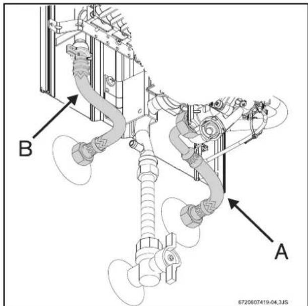
Fig. 5 Water connection

It is advisable to install a non-return valve on the supply side of the heater to avoid problems caused by sudden changes in supply pressure.
4.5 Gas connection

Danger: If local regulations are not follow exactly, a fire or explosion may result causing property damage, personal injury or loss of life.

Only use genuine accessories.
Any local by-laws and regulations pertaining to installation and use of gas-heated appliances must be observed. Please refer to the laws that should be attended in your country.
4.6 Startup
▶ Open the water and gas flow valves and check that all connections are leak-tight.
▶ Correctly insert the two 1.5 V batteries (Fig. 6) type R provided with the heater.
▶ Check if the flue gas safety device is functioning correctly, proceed as explained in section 7.3.
5 Operating instructions

Open all water and gas blocking devices. Purge the pipes.

Caution:
The front panel in the burner and pilot burner area may reach high temperatures, with risk of burning in case of contact.
5.1 Batteries
Battery insertion
▶ Insert the two 1.5 V R20 batteries.

Fig. 6 Inserting the batteries
Replacing the batteries
The batteries must be changed if the red LED starts flashing.

Fig. 7 Replacing the batteries
Precautions when using the batteries
- Do not dispose of batteries as domestic waste. Take them to appropriate collecting places for recycling.
- Do not insert flat batteries.
- Only use the type of batteries indicated
5.2 Before starting up the heater

Caution:
▶ Initial startup must be performed by a qualified technician who will provide the client with all the necessary information for optimum operation of the gas heater.
▶ Check if the gas indicated on the rating plate is the same as the one used at the location.
▶ Open the gas valve.
▶ Open the water valve.
5.3 Turning the heater on and off
Turning on
▶ Press the switch, position.

Fig. 8
Green light on = Main burner on

Fig. 9
Turning off
▶ Press the switch, position.
5.4 Power adjustment
Lower water temperature.
Less power.
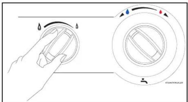
Fig. 10
Higher water temperature. More power.
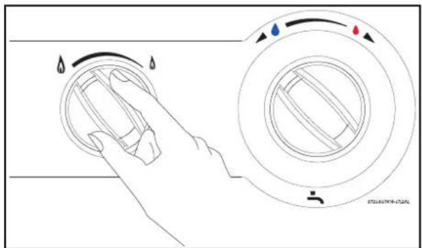
Fig. 11
5.5 Temperature/flow adjustment
▶ Turn anti-clockwise Increases flow and decreases water temperature.
![graph TD A["Start"] --> B{Condition} B -->|Yes| C["Process Step 1"] B -->|No| D["Process Step 2"] C --> E["End"] D --> E style A fill:#f9f,stroke:#333 style B fill:#ccf,stroke:#333 style C fill:#cfc,stroke:#333 style D fill:#fcc,stroke:#333](/content/2026/06/1266034/images/5170294ac6984f34d6851acee4e4372ad0ab1bc1672f63f91d639501af7aace1.jpg)
Fig. 12
▶ Turn clockwise. Decreases flow and increases water temperature.
Regulating the temperature to the minimum required value reduces energy consumption as well as the possibility of limescale deposits in the combustion chamber.
5.6 Purge the appliance
If there is a risk of freezing, proceed as follows:
▶ Remove the retaining clip from threaded bushing (pos. 1).
- Remove threaded bushing (pos. 2) from water valve. - Empty the appliance of all water.

Fig. 13 Purging
1 Retaining clip
2 Threaded bushing
6 Adjustments
6.1 Factory settings

Sealed elements must not be opened.
Natural gas
Heaters for natural gas H (G 20) are supplied sealed from the factory after being adjusted to the values indicated on the rating plate.

Heaters must not be turned on if the connection pressure is lower than 15 mbar or higher than 25 mbar.
Liquefied gas
Heaters for propane/butane (G31/G30) are supplied sealed from the factory after being adjusted to the values indicated on the rating plate.

Danger:
The following procedures must only be performed by a qualified technician.
It is possible to adjust the power using the burner pressure process, although a pressure gauge is necessary for this procedure.
6.2 Pressure adjustment
Accessing the adjusting screw
▶ Remove the front part of the heater (see 4.3).
Connecting the pressure gauge
▶ Unscrew the shut-off screw.
- Connect the pressure gauge to the measuring point for the burner pressure.

Fig. 14 Pressure measurement points
Maximum gas flow adjustment
▶ Remove the screw seal (Fig. 15).
▶ Turn on the heater with the power selector set to the left (maximum position).

Fig. 15 Maximum gas flow adjusting screw
▶ Open various hot water taps.
▶ Using the adjusting screw, regulate the pressure until obtaining the values indicated in the table 6.
▶ Seal the adjusting screw once again.
Minimum gas flow adjustment

The minimum gas flow adjustment is performed automatically after the adjustment of the maximum gas flow.
| Natural gas H | Butane | Propane | ||
| Injector code | WR11 | 8708202113(1,10) | 8708202130(0,70) | |
| 8708202124(1,20) | 8708202128(0,72) | |||
| WR14 | 8708202113(1,10) | 8708202128(0,72) | ||
| 8708202116(1,25) | 8708202132(0,75) | |||
| WR18 | 8708202115(1,15) | 8708202130(0,70) | ||
| 8708202116(1,25) | 8708202132(0,75) | |||
| Connection pressure (mbar) | WR11WR14WR18 | 20 | 30 | 37 |
| MAX (mbar) | WR11 | 12,7 | 28 | 35 |
| WR14 | 12 | 28 | 35 | |
| WR18 | 10,3 | 25,5 | 32,5 | |
Tab. 6 Burner pressure
6.3 Converting to a different gas type
Use only original conversion kits. Conversion must only be carried out by an accredited technician. Authentic conversion kits are supplied with installation instructions.
7 Maintenance
To ensure that gas consumption and the environmental load (pollution, etc.) remain as negligible as possible over a longer period of time, we recommend that you assure to have the appliance maintained on an annual basis (inspection) or if necessary (maintenance).
These jobs can only be done by a Junkers Technical Assistance delegate.

Maintenance must only be performed by a qualified technician.

Warning:
Before performing any maintenance work:
▶ Close the water flow valve.
▶ Close the gas flow valve.
▶ Use only authentic spare parts and accessories.
▶ Order the spare parts according to the spare parts catalogue for the heater.
- Substitute dismantled joints and o-rings with new ones.
▶ Only the following lubricants must be used:
- On hydraulic parts: Unisilikon L 641 (8 709 918 413)
- Threaded joints: HFt 1 v 5 (8 709 918 010).
7.1 Periodic maintenance tasks
Functional checks
▶ Ensure that all safety, regulatory and checking elements are in good working order.
Heat exchanger
▶ Inspect the heat exchanger.
▶ If it is dirty:
- Dismantle the chamber and remove the regulator.
– Clean the chamber with a pressurized water jet.
▶ If the dirt resists: soak soiled parts in hot water with detergent and clean carefully.
▶ If necessary: de-scale the interior of the heat exchanger and connection tubes.
▶ Reassemble the heat exchanger using new joints.
▶ Remount the regulator on its support.
Burner
▶ Inspect the burner annually and clean as necessary.
▶ If it is very dirty (grease, soot): Dismantle the burner and soak it in hot water with detergent and clean it carefully.
Water filter
- Replace the water filter installed in the inlet of the water valve.
Pilot and main burner
▶ Remove and clean pilot burner.
▶ Remove and clean pilot injector.

Warning:
Is forbidden to start up the appliance without water filter correctly assembled.
7.2 Startup after maintenance work
▶ Re-open all connections. Ensure there are no gas leaks.
Read chapter 5 "Use" and chapter 6 "Adjustments".
7.3 Flue gas safety device

Danger:
The flue gas safety device must not under any circumstances be switched off, simulated or replaced by any other component
Operation and precautions
The flue gas safety device checks the effectiveness of flue gas extraction by the flue. If it is inadequate, the appliance switches off automatically so that the combustion fumes do not escape into the room in which the appliance has been installed. The flue gas safety device resets after a cooling-down period.
If the appliance shuts down while in operation:
▶ Ventilate the room.
▶ 10 minutes later, turn on the heater once again.
Call a qualified technician if the same thing happens again.

Danger:
The user must never make any modifications to the appliance.
Maintenance*
If faults occur on the flue gas safety device, proceed as follows:
▶ Undo flue gas safety device fixing screw.
▶ Loosen temperature limiters connectors.
▶ Replace damaged component with new one and refit using the reverse of the procedure set out in the table above.
Function check*
Flue gas safety device function check:
▶ Disconnect flue pipe;
▶ Replace with pipe (about 50 cm long) with sealed end;
▶ Fit pipe vertically;
▶ Start up appliance at rated output and set temperature control to maximum temperature;
Under those conditions, the appliance should shut down after two minutes. Remove temporary pipe and reconnect flue pipe.
* This work may only be carried out by an approved engineer.
8 Problems
8.1 Problem/cause/solution
Assembly, maintenance and repairs must be performed by qualified technicians only. The following chart offers solutions to possible problems (solutions followed by an * must be undertaken by qualified technicians only).
| Problem | Cause | Solution |
| The heater does not ignite. | Batteries flat or not inserted correctly, or switch turned off. | Check position and replace them. |
| Slow and difficult ignition of the burner. | Flat batteries. | Replace them. |
| LED next to the switch flashes. | ||
| Water at low temperature. | Check the temperature selector position and adjust it according to the desired water temperature. | |
| Water is not heated, no flame. | Insufficient gas supply. | Check the reducer and replace it if inadequate or malfunctioning.Check if the bottles (butane) freeze during operation, and if so, move them to a warmer place. |
| The burner turns off the heater is operating. | Temperature limiter has tripped.Flue gas safety device has tripped. | Wait 10 minutes and restart the heater. If the problem persists, call a qualified technician.Vent the area. Wait 10 minutes and restart the heater. If the problem persists, call a qualified technician. |
| Reduced water flow. Insufficient water supply pressure. | Dirty taps or mixers.Water valve blocked.Combustion chamber blocked (limescale). | Check and correct.*Check and clean.Clean filter.*Clean and de-lime if necessary.* |
Tab. 7
9 Environmental protection
Environmental protection is a basic company strategy of Junkers. The quality of our products, profitability and environmental protection are equal-ranking goals for us. Laws and regulations concerning environmental protection are strictly observed. We use the best possible technology and materials, under economic considerations, to protect the environment
Packaging
We participate in the recycling program of the respective country to ensure optimal recycling.
All of our packaging materials are environmental-friendly and can be recycled.
Old appliances
Old appliances contain valuable materials that should be recycled.
The assemblies can be easily detached and synthetic materials are marked accordingly. The assemblies can therefore be sorted out and passed on for recycling or disposal.
- INSTALLATION MANUAL AND OPERATING INSTRUCTIONS
- GAS HEATERS
- MINIMAXX
- TABLE OF CONTENTS
- 1 WARNINGS AND SYMBOLS 3
- 2 INFORMATION ABOUT THE HEATER 4
- 3 REGULATIONS 9
- 4 INSTALLATION 10
- 5 OPERATING INSTRUCTIONS 12
- 6 ADJUSTMENTS 14
- 7 MAINTENANCE 15
- 8 PROBLEMS 17
- 9 ENVIRONMENTAL PROTECTION 18
- 1 WARNINGS AND SYMBOLS
- 1.1 SAFETY INSTRUCTIONS
- IF THERE IS A SMELL OF GAS
- IF THERE IS A SMELL OF BURNT GASES
- FITTING, MODIFICATIONS
- MAINTENANCE
- EXPLOSIVE AND INFLAMMABLE MATERIALS
- COMBUSTION AIR AND AMBIENT AIR
- CLIENT INFORMATION
- 1.2 KEY TO SYMBOLS
- 2 INFORMATION ABOUT THE HEATER
- 2.1 CATEGORY, TYPE AND APPROVAL NO
- 2.2 TECHNICAL IDENTIFICATION CODE
- 2.3 PACKAGE CONTENTS
- 2.4 DESCRIPTION OF THE HEATER
- 2.5 SPECIAL ACCESSORIES
- 2.6 DIMENSIONS
- 2.7 FUNCTIONAL DIAGRAM OF THE HEATER
- 2.8 ELECTRICAL DIAGRAM
- 2.9 FUNCTION
- 3 REGULATIONS
- 4 INSTALLATION
- DANGER: EXPLOSION
- 4.1 IMPORTANT INFORMATION
- 4.2 SELECTION OF THE PLACE OF INSTALLATION
- REQUIREMENTS REGARDING THE PLACE OF INSTALLATION
- COMBUSTION GASES
- CAUTION
- SURFACE TEMPERATURE
- AIR INTAKE
- 4.3 HEATER MOUNTING
- 4.4 WATER CONNECTION
- 4.5 GAS CONNECTION
- 4.6 STARTUP
- 5 OPERATING INSTRUCTIONS
- 5.1 BATTERIES
- BATTERY INSERTION
- REPLACING THE BATTERIES
- PRECAUTIONS WHEN USING THE BATTERIES
- 5.2 BEFORE STARTING UP THE HEATER
- 5.3 TURNING THE HEATER ON AND OFF
- TURNING ON
- TURNING OFF
- 5.4 POWER ADJUSTMENT
- 5.5 TEMPERATURE/FLOW ADJUSTMENT
- 5.6 PURGE THE APPLIANCE
- 6 ADJUSTMENTS
- 6.1 FACTORY SETTINGS
- NATURAL GAS
- LIQUEFIED GAS
- DANGER
- 6.2 PRESSURE ADJUSTMENT
- ACCESSING THE ADJUSTING SCREW
- CONNECTING THE PRESSURE GAUGE
- MAXIMUM GAS FLOW ADJUSTMENT
- MINIMUM GAS FLOW ADJUSTMENT
- 6.3 CONVERTING TO A DIFFERENT GAS TYPE
- 7 MAINTENANCE
- WARNING
- 7.1 PERIODIC MAINTENANCE TASKS
- FUNCTIONAL CHECKS
- HEAT EXCHANGER
- BURNER
- WATER FILTER
- PILOT AND MAIN BURNER
- 7.2 STARTUP AFTER MAINTENANCE WORK
- 7.3 FLUE GAS SAFETY DEVICE
- OPERATION AND PRECAUTIONS
- FUNCTION CHECK
- 8 PROBLEMS
- 8.1 PROBLEM/CAUSE/SOLUTION
- 9 ENVIRONMENTAL PROTECTION
- PACKAGING
- OLD APPLIANCES
Brand : Junkers
Model : WR 11-2 B
Category : Boiler