
Protect C.6000 S - Uninterruptible power supply AEG - Free user manual and instructions
Find the device manual for free Protect C.6000 S AEG in PDF.


| Product Type | Uninterruptible Power Supply (UPS) |
| Model | Protect C.6000 S |
| Brand | AEG |
| Power Rating | 6000 VA / 5400 W |
| Input Voltage | 230 V AC ±15% |
| Input Frequency | 50/60 Hz ±5% |
| Output Voltage | 230 V AC ±2% (on battery) |
| Output Frequency | 50/60 Hz ±0.5% (on battery) |
| Waveform | Pure Sine Wave |
| Battery Type | Sealed lead-acid, maintenance-free |
| Typical Runtime (half load) | Approximately 10-15 minutes |
| Recharge Time | 4-6 hours to 90% |
| Outlets | 8 x IEC C13 (battery + surge), 1 x IEC C19 (battery + surge) |
| Communication Ports | USB, RS-232, dry contacts |
| Software Included | AEG Power Management Software |
| Dimensions (W x D x H) | 428 x 660 x 86 mm (2U) |
| Weight | Approximately 52 kg |
| Operating Temperature | 0°C to 40°C |
| Safety Certifications | CE, TÜV, EN 62040 |
| Maintenance | Replace battery every 3-5 years, keep vents clean |
| Repairability | Hot-swappable batteries, user-replaceable fans |
Frequently Asked Questions - Protect C.6000 S AEG
User questions about Protect C.6000 S AEG
0 question about this device. Answer the ones you know or ask your own.
Ask a new question about this device
Download the instructions for your Uninterruptible power supply in PDF format for free! Find your manual Protect C.6000 S - AEG and take your electronic device back in hand. On this page are published all the documents necessary for the use of your device. Protect C.6000 S by AEG.
USER MANUAL Protect C.6000 S AEG
natural_image
Exterior view of a white industrial air conditioning unit (no visible text or symbols)AEG
PROTECT C.
PROTECT C. 6000 (S)
PROTECT C. 10000 (S)
Thank you for purchasing the AEG UPS PROTECT C. from AEG Power Solutions.
Safety information and operating instructions are included in this manual. To ensure correct use of the UPS, please read this manual thoroughly before operating it. Save this manual properly.
1 Notes on these Operating Instructions
Duty to Provide Information
These operating instructions will help you to install and operate the U _ninterruptible Power Supply (UPS) PROTECT C. 6000 (S) or PROTECT C. 10000 (S) as well as the associated external battery units PROTECT C. 6000BP or PROTECT C. 10000BP – all referred to as PROTECT C. in this document – safely and properly, and for its intended purpose. These operating instructions contain important information necessary to avoid dangers during operation.
Please read these instructions carefully prior to commissioning!
These operating instructions are a composite part of the PROTECT C.
The owner of this unit is obliged to communicate the full content of these operating instructions to all personnel transporting or starting the PROTECT C. or performing maintenance or any other work on the unit.
Validity
These operating instructions comply with the current technical specifications of the PROTECT C. at the time of delivery. The contents do not constitute a subject matter of the contract, but serve for information purposes only.
Warranty and Liability
We reserve the right to alter any specifications given in these operating instructions, especially with regard to technical data and operation, prior to start-up or as a result of service work.
Claims in connection with supplied goods must be submitted within one week of receipt, along with the packing slip. Subsequent claims cannot be considered.
The warranty does not apply to damage caused by non-compliance with these instructions (such damage also includes damaging the warranty seal). AEG will accept no
liability for consequential damage. AEG reserves the right to rescind all obligations such as warranty agreements, service contracts, etc. entered into by AEG and its representatives without prior notification in the event of maintenance and repair work being carried out with anything other than original AEG spare parts or spare parts purchased by AEG.
Handling
PROTECT C. is designed and constructed so that all necessary steps for start-up and operation can be performed without any internal manipulation of the unit. Maintenance and repair work may only be performed by trained and qualified personnel.
Illustrations are provided to clarify and facilitate certain steps.
If danger to personnel and the unit cannot be ruled out in the case of certain work, it is highlighted accordingly by pictograms explained in chapter 3.
Hotline
If you still have questions after having read these operating instructions, please contact your dealer or our "Hotline":
No part of these operating instructions may be transmitted, reproduced and/or copied by any electronic or mechanical means without the express prior written permission of AEG.
© Copyright AEG 2009. All rights reserved.
Table of Contents
1 Notes on these Operating Instructions....61
2 General Information....65
2.1 Technology....65
2.2 System Description....66
2.3 Technical Data....69
3 Safety 73
3.1 General Safety Instructions ....73
3.2 Accident prevention regulations....73
3.3 Qualified personal....74
3.4 Safety Instructions for PROTECT C. 74
3.5 Certification....77
4 Set-Up and Operation ....78
4.1 Unpacking and Inspection ....78
4.2 Transportation to the site ....79
4.3 Point of Installation....80
4.4 Overview: Connections, Operating / Display Elements .....81
4.4.1 Front View....81
4.4.2 Display 82
4.4.3 Rear view (connections): 83
5 Commissioning....85
5.1 Protection for the personnel....86
5.2 Mains connection (general)......86
5.2.1 Checklist for connectors ....86
5.2.2 Connection diameter and protection....87
5.3 One phase mains connector ....87
5.3.1 Preparation for the one phase mains connector .....87
5.3.2 Connection of the one phase mains connector.....88
5.3.3 Preparation for the load connection....88
5.3.4 Connection of the loads....89
5.4 External Battery Expansions ....89
5.5 Mechanic blocking of the PROTECT C....90
6 Electrical Start-Up 91
6.1 Operating....93
6.1.1 Normal Operation ......93
6.1.2 Battery Operation / Autonomy Operation .....94
6.1.3 Bypass Operation .....95
6.1.4 Manual bypass....96
6.1.5 Unit Overload....96
7 Interfaces and communication .....98
7.1 Computer interfaces RS232....98
7.2 Communication Slot....98
7.3 Shutdown and UPS management software....98
8 Signalling and Error Correction....100
8.1 Signalling ....100
8.1.1 Table overview of LED display / alarm signals...102
8.2 Fault Diagnosis / Fault Rectification....104
8.2.1 Error Messages....104
9 Parallel operation ....106
9.1 Functionality....106
9.2 Setup / connection of the parallel operation field .....107
9.3 Operation in parallel compound....108
9.3.1 Activation ......108
9.3.2 Modification in parallel compound .....110
10 Maintenance ....112
10.1 Charging the Battery ....112
10.2 Maintenance....112
10.2.1 Visual Check....112
10.2.2 Checking the Battery 113
10.2.3 Fan Checking....113
11 Storage, Dismantling and Disposal ....114
11.1 Storage 114
11.2 Dismantling....114
11.3 Disposal....114
12 Glossary....115
2 General Information
2.1 Technology

PROTECT C. is an Uninterruptible P _ower Supply (UPS) for essential loads such as PCs, workstations, servers, network components, telecommunication equipment and similar devices. It consists of:
♦ Mains filter with overvoltage protection (appliance protection/class D) and mains energy backfeed protection
◆ Rectifier section with PFC logic (power factor correction unit)
◆ Separate battery charger with switch mode power supply technology
♦ Integrated sealed, maintenance-free battery system (PROTECT C.6000 / C.10000) as energy storage medium with downstream DC/DC converter unit
♦ IGBT inverter for continuous supply of connected loads with sinusoidal AC voltage
◆ Automatic electronic bypass (SBS = S _tatic Bypass Switch) as additional passive redundancy
◆ Manual bypass for maintenance and service purposes (with SBS activation when activated)
◆ Digital signal processor controlled control unit

flowchart
graph TD
    A["Main"] --> B["Filter"]
    B --> C["Rectifier"]
    C --> D["Inverter"]
    D --> E["DC/DC booster"]
    E --> F["Battery system"]
    F --> G["CPU control unit"]
    G --> H["RS232 SNMP"]
    I["Manually operated service bypass"] --> J["SBS"]
    K["PFC"] --> L["Rectifier"]
    M["Load"] --> N["Mains filter"]
    O["Battery charger"] --> P["Rectifier"]
    Q["Inverter"] --> R["Rectifier"]
    S["DC/DC booster"] --> T["Rectifier"]
    U["Power Supply"] --> V["Ground"]
    W["Feedback to Rectifier"] --> X["Output"]
View of the PROTECT C. components
2.2 System Description
The UPS is connected between the public utility's mains and the loads to be protected.
The power section of the rectifier converts the mains voltage to DC voltage for supplying the inverter. The circuit technology used (PFC) enables sinusoidal current consumption and therefore operation with little system disturbance. A separate, second rectifier (charging REC set up using switch mode power supply technology) is responsible for charging or trickle-charging the battery connected in the intermediate circuit. The configuration of this charging REC means the harmonic content of the charging current for the battery is almost zero, so the service life of the battery is increased even more. The inverter is responsible for converting the DC voltage into a sinusoidal output voltage. A microprocessor-controlled control system based on pulse-width modulation (PWM) in conjunction with digital signal processor technology and extremely quickly pulsating IGBT power semiconductors of the inverter guarantee that the
voltage system on the protected busbar is of the highest quality and availability.
In the event of mains faults (e.g. current failures), the voltage continues to be supplied from the inverter to the load without any interruption. From this point onwards, the inverter draws its power from the battery instead of the inverter. No switching operations are necessary; this means there is no interruption in the supply to the load.
The automatic electronic bypass serves to increase the security of supply further. It switches the public mains directly through to the load if there is an inverter malfunction. As a result, the automatic bypass represents an extra passive redundancy for the load.
The integrated manual bypass ensures in case of service and/or maintenances a complete power supply of all connected loads. The internal electronic circuit (with exception of the protected manual bypass) can be enabled by the input fuse.
The maximum security of supply for connected loads is achieved by switching up to three PROTECT C. UPS appliances parallel. The n+x technology provides the highest possible availability by a single or double redundancy. On the other hand the power can be raised by using the single redundancy. In case of no redundancy the highest power is reached with the UPS. The relation between available power and active redundancy is explained in the following table:
Parallel system with PROTECT C. 6000 (S)
| Available Power | Number of UPS units | |||
| 1 2 3 | ||||
| Active redundancy level | 0 6 kVA | 12 kVA 18 | kVA | |
| 1 --- | 6 kVA 12 kVA | |||
| 2 --- --- | 6 kVA | |||
Parallel system with PROTECT C.10000 (S)
| Available Power | Number of UPS units | |||
| 1 2 3 | ||||
| Active redundancy level | 0 10 kVA 20 kVA 30 kVA | |||
| 1 --- 10 kVA 20 kVA | ||||
| 2 --- --- 10 kVA | ||||
2.3 Technical Data
Type power
| PROTECT C. 6000 (S) 6000 VA (cos φ = 0.7 lag.) |
| 4200 W |
| PROTECT C. 10000 (S) 10000 VA (cos φ = 0.7 lag.) |
| 7000 W |
UPS Input (single phase) 1ph\~ / N / PE
| Rated connection voltage 220 / 230 / 240 VacVoltage tolerance range 176 Vac – 276 Vac ± 3 % without battery operationNominal frequency 50 Hz / 60 Hz(automatic detection) |
Frequency tolerance range ± 4 Hz
Curr. consumption (full load)
PROTECT C. 6000 (S) 31 A
PROTECT C. 10000 (S) 50 A
Input power factor ≥ 0.98
UPS Output (single phase)
| Rated output voltage 220 / 230 / 240 Vac ±1 %(configuration via software"CompuWatch") |
Nominal frequency 50 Hz / 60 Hz ± 0.1 %
(depending on mains)
Voltage waveform Harmonic distortion
≤ 2% THD (linear load)
≤ 6% THD (non-linear load)
Current Crest Ratio 3:1
Overload behaviour until 105 % continuous;
105 % - < 130 % for 10 min.;
130 % for 1 s
Gapless automatic switch to SBS.
Cutoff after 1 minute at persisting overload (backswitch at damping
overload = load < 90%).
Overload behaviour up to 105 % continuous;
in battery mode > 105 % for 10 s
Short circuit behaviour 3 x I
_N for 300 ms
Battery
Autonomy time (full load with internal battery)
PROTECT C. 6000 8 min.
PROTECT C. 10000 5 min.
Autonomy times with external optional battery expansions (only for PROTECT C. models):
| Coupled battery modules | Autonomy times (full load)C.6000 C. 10000 |
| 1 | 25 min. 15 min. |
| 2 | 45 min. 25 min. |
| 3 | 60 min. 33 min. |
Rated direct voltage (intermediate circuit)
PROTECT C. 6000 (S) 240 Vdc
PROTECT C. 10000 (S) 240 Vdc
Battery charging current
PROTECT C. 6000 2.0 A
PROTECT C. 6000 S 4.2 A
PROTECT C. 10000 2.0 A
PROTECT C. 10000 S 4.2 A
Recharge time \~ 7 h (UPS with internal
to 90% of rated capacity
(PROTECT C. – models)
battery only)
\~ 11 h (with 1 battery expansion)
\~ 16 h (with 2 battery expansions)
\~ 24 h (with 3 battery expansions)
Type Sealed, maintenance-free
PROTECT C. 6000 12 V 7.2 Ah x 20
PROTECT C. 10000 12 V 9 Ah x 20
PROTECT C. 6000 BP 12 V 7.2 Ah x 20
PROTECT C. 10000 BP 12 V 9 Ah x 20
“S” versions with boosted battery charger for charging external battery (no integrated battery)
Communication
| Ports RS232SUB-D (9-pole)Communication slot for expansion(e.g. AS/400 / USB / SNMP, ...)Shutdown Software on CD “CompuWatch” for all popularoperating systems likeWindows, Linux, Mac OS X,Unix, FreeBSD, Novell, Sun |
General Data
| Classification VFI SS 111 to IEC 62040–3double-conversion technology | |
| Overall efficiency (full load) | |
| PROTECT C. 6000 (S) > 88 % | |
| PROTECT C. 10000 (S) > 88 % | |
| Noise level (1m distance) | |
| PROTECT C. 6000 (S) < 55 dB(A) | |
| PROTECT C. 10000 (S) < 55 dB(A) | |
| Type of cooling Forced coolingby variable speed fans | |
| Operating temperature range 0°C to +40°CRecommendation+15°C to +25°C (due to battery system) | |
| Storage temperature range 0°C to +40°C | |
| Relative humidity | < 95%, non-condensing |
Max. site altitude up to 1000m at rated power;
if the UPS is used above than
1000m, decreasing as follows:
| Altitude (m) | 1000 | 1500 | 2000 | 2500 | 3000 |
| Power | 100% | 95% | 90% | 85% | 80% |
Colour Blackline
Weight:
PROTECT C. 6000 90 kg
PROTECT C. 6000 S 35 kg
PROTECT C. 6000 BP 65 kg
PROTECT C. 10000 93 kg
PROTECT C. 10000 S 38 kg
PROTECT C. 10000 BP 68 kg
Dimension W x H x D:
PROTECT C. 6000 (S/BP) 260 mm x 717 mm x 570 mm
PROTECT C. 10000 (S/ BP) 260 mm x 717 mm x 570 mm
Guidelines
The PROTECT C. complies with the product norm EN 50091.
The CE symbol on the unit certifies the compliance to the EG guidelines for 73/23 EEC low voltage and for 89/336 EEC electromagnetic compatibility (EMC), when following the installation instructions in the manual.
For the 73/23 EEC low voltage guidelines
Reference number EN 62040-1-1 : 2003
For 89/336-EMV guidelines
Reference number EN 50091-2 : 1995
EN 61000-3-2 : 1995
EN 61000-3-3 : 1995
i
Warning:
This is a UPS product for restricted sales for users only with appropriate knowledge. To avoid interference, restrictions according installation or additional measures may be required.
3 Safety
3.1 General Safety Instructions
Canonical operation and maintenance as well as the complying with affiliated security regulations are imminent for the protection of personal and the readiness to use of the unit. The personnel that sets up, activates, operates and maintains the unit has to be aware and has to stick to the security regulations. Any activity may only be performed by qualified personnel with designated and intact tools, appliances, measuring units and expandable items.
The following pictograms are used in these operating instructions to identify danger, attention and information content:

Danger!
This instruction defines work and operation methods, which are to follow, to prevent fatal injury to the operator and other persons.

Attention!
This instruction defines work and operation methods, which are to follow, to prevent damage to the unit and parts of the unit.

Information!
Useful and important hints for the operation of the UPS and its external battery modules (special accessories).
3.2 Accident prevention regulations
The local regulation for accident prevention and the general security regulations according IEC 364 have to be followed unconditionally. Before working with PROTECT C. the following security rules must be adhered.
♦ Disconnect the unit from the mains
♦ Protect against reconnection
◆ Assure for no power
◆ Ground and short circuit system
◆ Cover or seals adjacent components still under power
3.3 Qualified personal
The PROTECT C. may only be transported, setup, connected and maintained by qualified personnel, that is aware do the legal security and installation regulations and knows how to apply them. All executions have to be supervised by responsible qualified personnel.
The qualified personnel have to be authorised by the responsible person for security rights affairs to execute the necessary tasks.
Qualified personnel have
◆ an education and experience in the relevant area of operation,
◆ know the applicable norms, rules, regulations and accident preventions rules,
◆ are educated in the functionality and the operation of the PROTECT C.,
◆ can identify and prevent dangers.
Regulations and definitions for qualified personnel are included in DIN 57105 / VDE 0105, part 1.
3.4 Safety Instructions for PROTECT C.
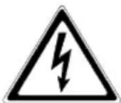
The UPS carries high voltage. The unit may only be opened by trained and qualified personnel. Repairs may only be carried out by qualified customer service staff!

The output may be live, even if the UPS is not connected to the mains, since the UPS has its own internal power supply (battery)!
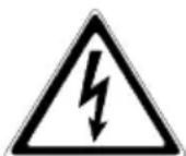
For health and safety reasons, the unit must be earthed correctly!
PROTECT C. may only be operated with or connected to a 220 V / 230 V / 240 V mains with protective grounding using a CE marked mains connection cable with PE conductor that has been tested in accordance with national standards.
Danger! Risk of burning!

The battery has powerful short circuit currents. Incorrect connection or isolation faults can lead to melting of the plug connections, sparking potential and severe burns!

The unit has a warning signal that sounds when the battery voltage of PROTECT C. is exhausted or when the UPS is not working in its normal mode (chapter 8, page 102).

Observe the following safety instructions to ensure permanent operational safety of and safe work with the UPS and the battery modules (special accessories):
♦ Do not dismantle the UPS!
The UPS does not contain any parts that require regular maintenance. Bear in mind that the warranty will be invalidated if the unit is opened!
◆ Do not install the unit in direct sunshine or in close proximity of heaters!
◆ The unit is designed to be installed inside in heated rooms. Never install the housing in the vicinity of water or in an excessively damp environment!
◆ Condensation may occur if the UPS is brought from a cold environment into the room where it is to be installed. The UPS must be absolutely dry prior to start-up. As a result, leave it to acclimatise for at least two hours.
◆ Never connect the mains input to the UPS output, and vice versa!
◆ Ensure that no fluids or foreign bodies can penetrate the housing!
Do not block the air vents of the unit! Keep children away from the unit and ensure that objects are never inserted through the air vents!
Do not connect household appliances such as hairdryers to the UPS! Also take care when working with motor loads. It is essential to avoid back-feeding the inverter, e.g. if the load is intermittently operated in regenerative mode.

Danger! Electric shocks!
Even after the mains voltage has been disconnected, the components within the UPS remain connected to the battery and can thus cause electric shocks. It is therefore imperative to disconnect the battery circuit before carrying out any maintenance or repair work!
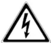
If it is necessary to replace the battery or carry out maintenance work, this must be done by or under the supervision of a specialist familiar with batteries and the necessary safety precautions!
Only authorised persons are allowed in the vicinity of the batteries!
When replacing the batteries, the following must be observed: Only ever use identical maintenance-free sealed lead batteries with the same data as the original batteries.

Danger! Explosive!
Never throw batteries into open fire.
Never open or damage batteries. (Electrolyte may leak out and damage skin and eyes. It may be toxic!)
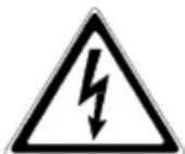
Batteries can cause electric shocks and high short-circuit currents.
Take the following safety precautions when working with the batteries:
◆ Take off watches, rings and other metallic objects!
◆ Always use tools with insulated handles!
3.5 Certification
AEG
Power Solutions
Declaration of Conformity
Document - No. CE 0063
We
declare under our sole responsibility that the product
Uninterruptible Power Supply (UPS)
Protect C.6000(S) / C.10000(S)
Protect C.6000R
to which this declaration relates is in conformity with the following standards or other normative documents
EN 50091-1-1:1996
EN 50091-2:1995 clause 2.4/2.5 restrictive sales
Following the provisions of directives
89 / 336 / EEC
EMC Directive
73/23/EEC
Low Voltage Directive
93/68/EEC
Marking Directive
Year of labelling the CE - Mark: 2005
Germany, 59581 Warstein, 03.12.2008
AEG Power Solutions GmbH Quality Management

AEG Power Solutions GmbH Product Management Compact UPS

4 Set-Up and Operation
4.1 Unpacking and Inspection
The device has been fully tested and inspected. Although the device has been packed and shipped with the usual degree of care, damage during transport cannot be ruled out completely.

Claims for damage during transport must always be made with the transport company!
Check the shipping container for damage on arrival. If necessary, ask the transport company to check the goods and make a record of the damage in the presence of the member of staff from the transport company. Don't turn on the unit and register the damage with the AEG representative or dealer immediately.
Check the delivery is complete:
♦ PROTECT C.(S) with 6000 or 10000 VA
◆ 25 pin parallel operation cable
◆ RS 232 communication cable
◆ CD with "CompuWatch" management software
♦ Operating instructions
Delivery of external battery modules includes:
◆ External battery unit
♦ Special battery connection cable
Please contact our hotline (see page 62) in case of any discrepancy.
The original packaging provides effective protection against mechanical shocks and should be retained so the unit can be transported safely later on.
Please keep the plastic packaging bags away from babies and children in order to safeguard against suffocation accidents.
Handle the components with care. Please take into account the weight. It may be necessary to engage the help of a second person.
4.2 Transportation to the site
The PROTECT C. provides for easy transportation to the site of installation transport rolls. It is recommended to position the USP such that
◆ the connection tasks can be performed easily;
◆ there is enough space for perfect operation and if necessary for periodical and exceptional maintenance; In this context the cables should be long enough, to be able to move the UPS (for opening the UPS) without switching it off;
◆ the UPS is protected against atmospheric influences;
◆ the humidity and the temperature remain in the specific range;
◆ the fire protection norm are complied.
The battery life time depends strongly of the environmental temperature. The temperature should lie between +15° and 25°C.

Attention!
Only transport the PROTECT C. in upright position. Don't tilt or put on the edges! Prevent dislocation of centre of gravity!
Be sure not to store or use any magnetic storage media near the PROTECT C.
4.3 Point of Installation
Note the following points when setting up the UPS system and its external battery units (special accessories):
◆ The contact surface must be smooth and in level. It must also be sufficiently strong and sturdy to avoid vibration and shock loads.
◆ Make sure the mounting is able to support the weight: This is particularly important in conjunction with external battery units (special accessories).
◆ Set up the units so that adequate air circulation is assured. There must be at least 100 mm clearance at the back for ventilation purposes. Do not block the intake openings on the front and, if present, on the side of the unit. There must be a gap of at least 50 mm here.
◆ Set up external battery units (special accessories) on the side of the UPS system. To ensure the greatest possible mechanical stability, you should not set up the external battery unit(s) above or below the UPS system.
◆ Avoid extreme temperatures! We recommend an ambient temperature of 15 °C to 25 °C in order to maximise the service life of the batteries. Do not expose the units to direct sunlight or operate them close to other heat sources such as radiators.
♦ Protect the units against external effects (in particular moisture and dust). In this regard, please also refer to the instructions in chapter 4.2, page 79 in these operating instructions.
If you transport the unit from a cold room into a warm one, or if the room temperature suddenly drops then condensation may form inside the unit. To avoid any damage due to condensation, leave the unit to acclimatise for 2 hours before you switch it on.
4.4 Overview: Connections, Operating / Display Elements
4.4.1 Front view

natural_image
Two identical AEG industrial vacuum cleaner units with control panel and ventilation grilles, shown from different angles (no text or symbols visible)PROTECT C. 6000 (S) PROTECT C. 10000 (S)
4.4.2 Display

Explanations
- OFF - Pushbutton
- ON / Alarm off - Pushbutton
- Orange LED bypass
- Green LED inverter
- Orange LED for battery mode (Battery)
-
Green LED for net state (Line)
-
-
- Bar graph LEDs for UPS battery utilization resp. capacity (remaining autonomy time)
-
-
LED load (0-35%) battery capacity (81-100%)
-
LED load (36-55%) battery capacity (61-80%)
-
LED load (56-75%) battery capacity (41-60%)
-
LED load (76-95%) battery capacity (21-40%)
-
LED load (96-105%) battery capacity (0-20%)
-
LED for battery problem
You will find detailed explanations of the displays on page 100.
4.4.3 Rear view (connections):
PROTECT C. 6000 (S)
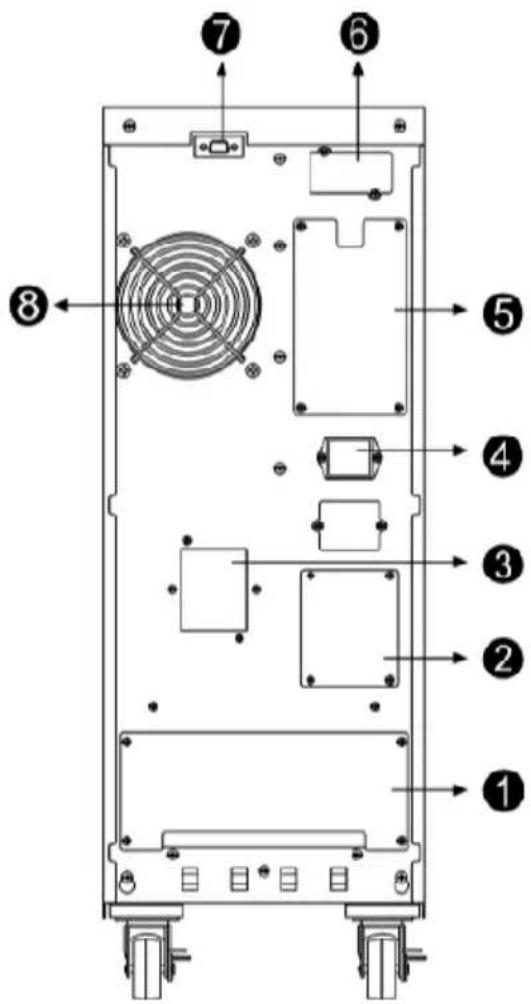
PROTECT C. 10000 (S)

Comments:
- Connectors for mains input and output, additional connectors for setting single and parallel operation
- Manual bypass switch
- Mains input circuit breaker
- Connection for external battery module
- Connector for parallel operation
- Communication slot for optional expansion cards, e.g. SNMP, USB, AS/400, ...
- Communication interface RS232 (9-pin SUB-D socket)
- Vent (Attention: at least 10 cm of free area are required behind the vent for free ventilation!)
5 Commissioning

Attention
Before any work is started, ensure that the cables are free of tension and no power can be switched on.

To prevent a deformation of the bus-bar and to keep the foot of the terminal free of torsion, it is recommended to hold the cable when removing the terminal screw.
The grounding protection prevents inappropriately high contact tension with reachable metal pieces. The grounding of the PROTECT C. is realised via the grounding screw (/PE). Before starting ensure that the PROTECT C. is grounded according the regulations, e.g. VDE 0100.
Before starting the connection tasks check that:
◆ the values of the mains voltage (input voltage) and frequency complies with the values on the label on the UPS,
◆ the grounding connection complies with the IEC norms or with the regional regulations,
◆ the UPS is connected to the mains via a separate and fused line in a preswitched NS distribution,
◆ the power fuse in the NS distribution has the same or higher value as indicated on the label on the rear of the UPS appliance.
5.1 Protection for the personnel
Before setting up the UPS appliance and the external battery modules (optional accessory) check the following:
♦ Disconnect the unit from the mains.
♦ Protect against reconnection.
◆ Assure for no power.
◆ Ground an short circuit system.
◆ Cover or seals adjacent components still under power.
5.2 Mains connection (general)
To guarantee the correct operation of the UPS and the optional accessories it is necessary to supply the mains line with the respective protection.
5.2.1 Checklist for connectors
The connection and grounding terminals are the same for all the PROTECT C. The cables are connected as follows:
◆ Remove the cover of the terminals.
- Introduce the cables from underneath resp. the rear into the terminals area of the PROTECT C.
◆ Connect the protective conductor terminal (PE) at the marked position.
◆ Connect the single lines on the respective terminals.
♦ Fix the cable for strain relief to the cable connection bus-bar.
◆ Check cable for perfect fit, if necessary fasten screw again.
◆ Remove cable pieces, tools, screws etc. from the terminal panel.
♦ Fix cover of the terminals again.
5.2.2 Connection diameter and protection
Please gather the minimal dimensions from the following table:
| Type PROTECT | C. 6000 (S) C. 10000 (S) | |
| Diameter | ||
| Mains line | 6 mm^2 | 10 mm^2 |
| Loads connector | 6 mm^2 | 10 mm^2 |
| Protection | ||
| Mains fuse 32 A 50 A | ||
Connection diameter and protection
5.3 One phase mains connector
5.3.1 Preparation for the one phase mains connector
Before starting the connection tasks check that:
◆ the values of the mains voltage (input voltage) and frequency complies with the values on the label on the UPS,
◆ the grounding connection complies with the IEC norms or with the regional regulations,
◆ the UPS is connected to the mains via a separate and fused line in a preswitched NS distribution,
◆ the prefuse or the power fuse in the NS distribution has the same or higher value as indicated on the label on the rear of the UPS appliance,
◆ the connection line from the prefuse to the UPS has to have a minimal diameter as defined in table: „Connection diameter and protection“

The UPS carries high voltage. The unit may only be installed or opened by trained and qualified personnel. Repairs may only be carried out by qualified customer service staff!
5.3.2 Connection of the one phase mains connector
To protect the personnel during installation, ensure that the connection takes place and the following precautions:
◆ No mains power present.
◆ Loads are switched of.
◆ The PROTECT C. is switched of (display completely off).
To activate the PROTECT C. execute the following steps:
◆ Set Manual bypass „Maintenance Switch“ to “Bypass” on the rear of the UPS. Remove the four screws of the cover (Pos. 2, page 83/84).
◆ Set the mains input circuit breaker (Pos. 3, page 83/84) to position “OFF”.
Connect the UPS terminal „PE“ (Ground) with the associated ground terminal in the distribution cabinet.
Connect the mains supply cable with the NS distributor to the „INPUT“ terminal in the UPS:
$$ ⓜ / P E = G r o u n d $$
$$ N = \text { Neutral line } $$
$$ L = \text { Phase } $$

Check the bridge between „JP1“ and „JP2“ (Terminal label „JUMPER“).
Only remove the cable, when using the PROTECT C. in parallel operation with appliances of the same type (see chapter 9).
5.3.3 Preparation for the load connection
Before connecting the loads to the UPS, it is necessary to ensure that the rated power of the label of the UPS is higher or equal to the sum of the power consumption of the loads.
The output of the PROTECT C. should supply the sub distribution in separate power circuits. Check for a selective protection of the circuits.
For the connection between PROTECT C. and the sub distribution cable diameters according to table on page 87 are
recommended. In the sub distribution the following indications are necessary:
♦ Maximal total load
♦ Maximal total load for the separate load power circuits

In the case of one common distributor cabinets (Circuits for mains and UPS power) each has to be labelled separately (Mains or UPS).
5.3.4 Connection of the loads
To protect the personnel during installation, ensure that the connection takes place and the following precautions:
◆ No mains power present.
◆ Loads are switched of.
◆ The PROTECT C. is switched of (display completely off).
To activate the PROTECT C. execute the following steps:
◆ Set manual bypass „Maintenance Switch“ to “Bypass” on the rear of the UPS. Remove the four screws of the cover (Pos. 2, page 83/84).
◆ Set the mains input circuit breaker (Pos. 3, page 83/84) to position “OFF”
Connect the "OUTPUT" of the UPS with the associated terminals.
$$ \begin{array}{l} \text { / PE = Ground } \ \mathrm{N=Neutralline} \ \mathrm{L=Phase} \end{array} $$
5.4 External Battery Expansions
To achieve longer backup time, it is possible to connect multi-battery packs. Connect exclusively the following products together:
PROTECT C. 6000 with PROTECT C. 6000 BP PROTECT C. 10000 with PROTECT C. 10000 BP
PROTECT C. with 1 battery expansion

natural_image
Technical line drawing of a dual-chamber electronic device with fan, buttons, and wheels (no text or symbols)Fig.: PROTECT C. 6000 and C. 6000BP
- Check the correct fit of the UPS and the battery unit (the casings e.g. have to have the same dimension).
- Now connect both battery connectors using the supplied battery connection cable. When connecting, make sure that you push the plug quickly and firmly in the battery connectors.
Proceed analogue accordingly for a 2. and 3. battery expansion.
5.5 Mechanic blocking of the PROTEC C.
After finishing the connection procedure fix the connection terminal cover again. At the final position fix the cabinets with the breaks against moving away.
6 Electrical Start-Up
Verify that UPS voltage of your country corresponds to your equipment voltage. The default setting is set to 230 V. Output voltage on the UPS system can be adjusted with the software "CompuWatch" in steps of 220 Vac and 240 Vac.
Turn on the PROTECT C. to the mains
- Ensure, that the connection have been realised according to the installation guide.
- Ensure, that all loads are switched of.
- Set manual bypass „Maintenance Switch“ back to “UPS” on the rear of the UPS (Pos. 2, page 83/84). Fix the four screws of the cover.
- Put the prefuse of the low voltage main distributor (there, where the UPS system is connected on the input side with the mains) back in resp. switch the corresponding line fuse on.
- Activate the mains input circuit breaker (Pos. 3, page 83/84). If necessary switch it to "ON".

Default setting: The supply of the loads comes via the integrated bypass (Modification of the configuration with the provided Software „CompuWatch“). Don't switch on the loads yet.
-
Now switch on the UPS. To do this, press and hold the UPS ON switch for about 2 seconds.
-
While powering up, the UPS will perform self-diagnosis, the Load/Battery level LEDs will be turned on and then off one after another in ascending order. After synchronising the inverter successfully the LED “Inverter” will go on after a few seconds, with the UPS in normal mode. If the power supply is in order (mains within the range) an additionally the LED “Line” will light up.
i
Please shut down the entire system if you cannot solve any problems which occur. Press the OFF button for about 2 seconds. Disconnect the UPS from the mains by pressing the mains input circuit breaker (Pos 3, page 83/84). Please contact our hotline (page 62).
- When all displays are lit as described, switch on your loads one after the other. Note the maximum permitted UPS load when doing this.
i
Behaviour when switching off:
The behaviour after switching off the UPS with the mains switch (OFF) can be defined with the Software CompuWatch. The UPS can switch to bypass mode or can be switched of right away.
6.1 Operating
The following operation modes are possible:
Operation with existing mains (6.1.1)
Operation with faulty mains (6.1.2)
Operation with faulty inverter (6.1.3)
Manual bypass (6.1.4)
6.1.1 Normal Operation

flowchart
graph TD
    A["Mains"] --> B["Main input circuit breaker"]
    B --> C["REC"]
    C --> D["SBS"]
    D --> E["INV"]
    E --> F["Manual bypass"]
    F --> G["Safety bus-bar"]
    G --> H["Load"]
    I["Energy flow with existing mains"] --> D
    J["Shematic illustration"] --> K["Battery"]
    L["Charger"] --> M["~"]
    N["Manual bypass path"] --> O["REC"]
    P["Shromatic illustration"] --> Q["Battery"]
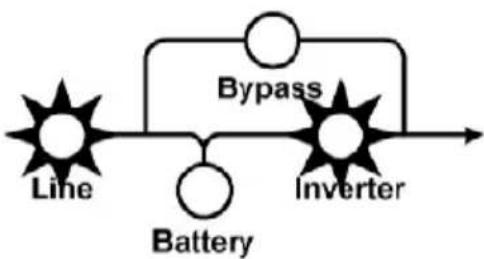
Once you have connected the UPS to a suitable mains connection, you can start operation using the UPS main switch. Normally, the UPS operates continuously. The UPS now supplies the output with voltage, this being signalled by the symbols mains (LED Line) and inverter (LED Inverter) symbols which light up permanently.
This is often referred to as “online” mode. It offers the greatest protection, in particular when there are mains fluctuations and mains failures, because the loads are supplied continuously with voltage with no interruptions in this operating mode.
flowchart
graph LR
    A["Line"] --> B["Battery"]
    B --> C["Inverter"]
    C --> D["Bypass"]
    D --> A
The LED bargraph (LED chain on the left hand side of the ON / OFF button) show during operation the actual utilization of the UPS (s. chapter 8.1.1, page 102).
6.1.2 Battery Operation / Autonomy Operation

flowchart
graph TD
    A["Mains"] --> B["Main input circuit breaker"]
    B --> C["REC"]
    C --> D["SBS"]
    D --> E["INV"]
    E --> F["Manual bypass"]
    F --> G["Safety bus-bar"]
    G --> H["Load"]
    I["Charger"] --> J["Battery"]
    K["Energy flow with faulty mains"] --> D
    L["Shematic illustration"] --> B
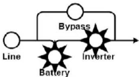
The mains is not within the required tolerance range or has failed. In this case power is supplied to the inverter from the charged battery without interruption. The power supply to the loads is therefore also ensured in the event of a mains failure. This drains the capacity of the battery and it is discharged. This status is signalled by the battery symbol (LED Battery) lighting up, as well as an intermittent acoustic signal every 4 seconds and every second before switching off. This can be suppressed by pressing the “Alarm off” button. With decreasing battery capacity the alarm is activated automatically. Depending on the expansion level, age and condition of the battery and in particular on the load to be supplied, the standby time can vary from a few minutes to several hours.
flowchart
graph LR
    A["Line"] --> B["Battery"]
    B --> C["Bypass"]
    C --> D["Inverter"]
    D --> E["Output"]
The inverter is switched off if the battery voltage drops below a factory-set minimum voltage value.
Never store the unit in this condition! The discharged battery system should be recharged within a week at the latest.
When the voltage and frequency are within the tolerance range once more, the inverter and the battery charger switch back on automatically. The inverter then continues supplying
the inverter and the battery charger takes over charging the battery.
The LED bargraph (LED chain on the left hand side of the ON / OFF button) show during operation the actual utilization of the UPS (chapter 8.1.1, page 102).
6.1.3 Bypass Operation

flowchart
graph TD
    A["Mains"] --> B["Manual bypass path"]
    B --> C["REC"]
    C --> D["SBS"]
    D --> E["INV"]
    E --> F["Charger"]
    F --> G["Battery"]
    G --> H["Manual bypass"]
    H --> I["Safety bus-bar"]
    I --> J["Load"]
    K["Shematic illustration"] --> L["Mains input circuit breaker"]
    M["Energy flow with faulty rectifier"] --> N["Energy flow with faulty rectifier"]
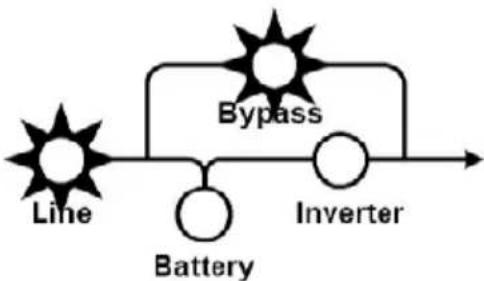
If the inverter is overloaded or if overtemperature is detected, e.g. also if an inverter defect is detected, voltage is supplied to the load via the bypass that switches on automatically. This is signalled by the bypass symbol.
flowchart
graph LR
    A["Line"] --> B["Battery"]
    B --> C["Bypass"]
    C --> D["Inverter"]
This function is also referred to as passive redundancy. It protects against total failure of the voltage supply on the protected busbar, however in the operating status that is now attained, mains faults would have a direct effect on the load.
As a result, the electronics continuously attempt to switch back to "online" / normal operating status (e.g. when the overload or overtemperature no longer applies).
The bypass is a mechanical link that switches extremely rapidly. It is located between the load and the mains. The associated synchronisation unit in the bypass ensures that
the frequency and phase of the inverter voltage is synchronised with the mains.

The LED bar graph functions as display for USP utilisation. The signal goes off during this operations status every 2 seconds.
6.1.4 Manual bypass

flowchart
graph TD
    A["Mains"] --> B["Manual bypass path"]
    B --> C["REC"]
    C --> D["SBS"]
    D --> E["INV"]
    E --> F["Charger"]
    F --> G["Battery"]
    G --> H["Manual bypass"]
    H --> I["Safety bus-bar"]
    I --> J["Load"]
    K["Shematic illustration"] --> L["Mains input circuit breaker"]
    M["Energy flow with active manual bypass"] --> N["MANUAL BYPASS"]
The manual bypass allows maintenance and service personnel to work on the PROTECT C. without switching of the appliance.

If the mains supply fails if the manual bypass is activated, the loads supply fails completely. For this reason, it is important to switch as fast as possible to normal operation mode.
6.1.5 Unit Overload
The load on the UPS should never exceed the specified rated load of the unit. If a unit overload occurs nevertheless (from 105% of the specified unit rated load) the fault LED is turned on accompanied with a signal tone (twice per second). The connected loads continue to be supplied for a certain time depending on the level of the overload. However, the connected load must be reduced without delay.
Non-observance of the "Unit overload" condition may cause the total loss of all UPS functions!
Also avoid short-term unit overloads, which may, for example, occur when connecting a laser printer or laser fax machine.
Do not connect any household appliances or machine tools to the UPS.

Never connect or switch on any additional loads to the UPS if there is a mains failure, i.e. if the UPS is working in emergency power operation!
As a rule, if there has never been an overload during normal operation, there will not be one during battery operation either.

The signalling of the fault LED in combination with a continuous alarm points out a switching of fault. Follow the instructions in chapter 8.2.
7 Interfaces and communication
7.1 Computer interfaces RS232
The UPS offers various interfaces to manage the system and to comfortable readout state information and important parameters. The communication protocol is optimized for operation with the shutdown and UPS management software "CompuWatch" from AEG. To connect the UPS to your computer use the provided RS232 communication cable by attaching them to a free port of your pc.
RS232 interface: The interface is connected via a 9 pole Sub-D connector on the back of the unit (pos. 4 p. 83/84). PINs: 2 = RxD; 3 = TxD; 5 = GND.
7.2 Communication Slot
If the cover on the rear of the UPS is removed (pos. 8 p. 83/84), additional optionally available communication components can be installed there.
AS/400 board: Slot card with status messages, realised via potential-free relay contacts
USB board: Slot card for external USB connection
SNMP board: Slot card for direct connection of the UPS to the Ethernet network with RJ 45 (TCP/IP)
Details can be found in the description enclosed with the particular optional component. Other boards are in preparation.

The usage of the communication slot deactivates the RS232 interface from chapter 7.1.
7.3 Shutdown and UPS management software
The "CompuWatch" software specially developed for these purposes by AEG continuously checks the mains supply and the UPS status.
In conjunction with the "intelligent" UPS, this ensures that the availability of IT components and data security is guaranteed. The "CompuWatch" shutdown software supports different operating systems: Windows 98SE/ME, Windows NT/2000/XP, Windows Vista, Linux, Novell Netware, IBM AIX, HP-UX, SUN Solaris, Mac OS, and others.

bar
UPS Monitor | Input Voltage | Load (%) | Autonomy Time (Min.) | | :--- | :--- | :--- | | 570V | - | 109 | | 100V | 100% | 86 | | 50V | 50% | 60 | | 220V | 0% | 40 | | 94 Min. | 94 Min. | 0 |Refer to the manual on the CD for details about installing the software on the various operating systems. Updates can be downloaded under www.aegpartnernet.com >> PRODUCTS >> Software >> CompuWatch
8 Signalling and Error Correction
8.1 Signalling

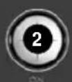
- OFF push button (OFF): Press the OFF switch for about 2 seconds to switch on the UPS
- ON push button (ON): Press the ON switch for about 2 seconds to switch off the UPS.
Deactivate acoustic alarm: By pressing this switch for about 2 seconds during the alarm an acoustic alarm can be deactivated.
UPS Test: To execute an UPS self test press this button for about 2 seconds in the normal operation mode.
-
LED Bypass: The orange-coloured LED lights up when the UPS system is supplying voltage provided by the mains power via the bypass.
-
LED Inverter: The green-coloured LED lights up if the UPS system is supplying voltage provided by the mains power via the inverter.
-
LED Battery: The orange-coloured LED lights up when power is supplied by the batteries.
-
LED Line (Mains status): The green LED lights up if mains voltage is in a specified range of tolerance.
-
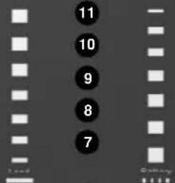
-11. LED Bargraph for UPS battery utilization resp. capacity (remaining autonomy time)
These LEDs show the load of the UPS system if the mains power is available (normal operation):
- orange LED 96%-105%
- green LED 76%-95%
- green LED 56%-75%
- green LED 36%-55%
- green LED 0%-35%
In the battery operation, the LEDs indicate the capacity of the batteries:
- orange LED 0%-20%
- green LED 21%-40%
- green LED 41%-60%
- green LED 61%-80%
-
green LED 81%-100%
-
LED Fault: The red LED lights up and an acoustic warning signal is issued continuously when the UPS system is in fault condition.
8.1.1 Table overview of LED display / alarm signals
| No. | Operation status | LED Display (see chapter 8 on page 42) | Alarm signal | ||||||||||
| 12 | 11 | 10 | 9 | 8 | 7 | 6 | 5 | 4 | 3 | ||||
| 1 | Norm.al operation (Mains there) | 0% - 35% Utilization | ✕ | ✕ | ✕ | none | |||||||
| 2 | 36% - 55% Utilization | ✕ | ✕ | ✕ | ✕ | none | |||||||
| 3 | 56% - 75% Utilization | ✕ | ✕ | ✕ | ✕ | ✕ | none | ||||||
| 4 | 76% - 95% Utilization | ✕ | ✕ | ✕ | ✕ | ✕ | ✕ | none | |||||
| 5 | 96% - 105% Utilization | ✕ | ✕ | ✕ | ✕ | ✕ | ✕ | ✕ | none | ||||
| 6 | Battery operation | 0% - 20% Capacity | ✕ | ✕ | ✕ | 1 signal per second | |||||||
| 7 | 21% - 40% Capacity | ✕ | ✕ | ✕ | ✕ | 1 signal every 4 seconds | |||||||
| 8 | 41% - 60% Capacity | ✕ | ✕ | ✕ | ✕ | ✕ | 1 signal every 4 seconds | ||||||
| 9 | 61% - 80% Capacity | ✕ | ✕ | ✕ | ✕ | ✕ | ✕ | 1 signal every 4 seconds | |||||
| 10 | 81% - 100% Capacity | ✕ | ✕ | ✕ | ✕ | ✕ | ✕ | ✕ | 1 signal every 4 seconds | ||||
| 11 | Load supply via bypass of UPS | ✕ | ✕ | ✕ | ✕ | ✕ | ✕ | ✕ | 1 signal every 2 minutes | ||||
| 12 | Appliance overload UPS in INV mode | ✕ | ✕ | ✕ | ✕ | ✕ | ✕ | ✕ | ✕ | 2 signals per second | |||
| 13 | Appliance overload UPS in bypass mode | ✕ | ✕ | ✕ | ✕ | ✕ | ✕ | ✕ | ✕ | 2 signals per second | |||
| 14 | Mains abnormal (e.g. L1/N mixed up) | ✕ | ✕ | ✕ | ✕ | ✕ | ✕ | ✕ | ✕ | ✕ | ✕ | ||
| 15 | Overload in battery mode, prenotification | ✕ | ✕ | ✕ | ✕ | ✕ | ✕ | ✕ | ✕ | 2 signals per second | |||
| 16 | Overload in battery mode, cutoff | ✕ | ✕ | ✕ | Continuous alarm signal | ||||||||
| 17 | Overtemperature failure | ✕ | ✕ | ✕ | ✕ | Continuous alarm signal | |||||||
| 18 | Inverter failure | ✕ | ✕ | ✕ | ✕ | Continuous alarm signal | |||||||
Note: = LED shines
※ = LED flashes
■ = Display- / Alarm signal state undefined; unimportant for displayed operation state
Continuation overview of LED display / alarm signals
| No. | Operation status | LED Display (see chapter 8 on page 42) | Alarm signal | |||||||||
| 12 | 11 | 10 | 9 | 8 | 7 | 6 | 5 | 4 | 3 | |||
| 19 | Output short circuit | ✕ | ✕ | ✕ | ■ | Continuous alarm signal | ||||||
| 20 | BUSvoltage anomalous | ✕ | ✕ | ■ | ■ | Continuous alarm signal | ||||||
| 21 | DC circuit faulty; pos. battery error | ✕ | ■ | ※ | ■ | ■ | 1 signal per second | |||||
| 22 | Battery charger faulty | ✕ | ✕ | ✕ | ■ | ■ | Continuous alarm signal | |||||
| 23 | Vent error | ✕ | ✕ | ✕ | ■ | ■ | ■ | ■ | 1 signal per second | |||
| 24 | Fault of inverter output relay | ✕ | ✕ | ✕ | ■ | ■ | Continuous alarm signal | |||||
| 25 | Communication interrupted | ✕ | ✕ | ✕ | ■ | ■ | Continuous alarm signal | |||||
| 26 | Parallel operation error | ✕ | ✕ | ✕ | ✕ | ■ | Continuous alarm signal | |||||

Note.: = ED shines
※ = LED flashes
■ = Display- / Alarm signal state undefined; unimportant for displayed operation state



8.2 Fault Diagnosis / Fault Rectification
The PROTEC C. generates detailed error messages. Support personal can localise and interpret faults quickly and precisely. Search for the right method and solutions recommendations referring to the errors according to chapter 8.1.1.
8.2.1 Error Messages
| Problem Cause Solution | ||
| UPS does not start. No indication, no warning tone even though system is connected to mains power supply. | Mains and battery voltage not in the tolerance range, possible battery deep discharge. | Check building wiring socket outlet and input cable. |
| LED “Line” blinks and audible signal sounding every 3 minutes. (Error No. 14) | Phase and neutral conductor at input of UPS system are reversed. | Rotate mains power socket by 180° or connect UPS system. |
| LED “Line” blinks and LED “Battery” lights up. | Input power and/or frequency are out of tolerance. | Check input power source (Voltage, frequency) and inform house electrician if necessary. |
| LED “Inverter” and LED “Battery” lights up, and audible signal sounding every 4 seconds. LED “Inverter” and LED “Battery” lights up, and audible signal sounding every seconds. (Battery state No. 12/13) | Mains power supply has failed. Automatic switch to battery mode. | Try to replace mains supply (possibly triggered fuse in sub-distribution). When audible signal sounding every second, battery is almost empty. At this point it is time to proceed with an system shutdown of all your IT equipment. |
| LED “Fault” lights, warning tone once a second. (Error No. 12/13) | Overload of the UPS system. | Reduce utilizations of UPS by removing loads of UPS output. |
| Emergency supply period shorter than nominal value. | Batteries not fully charged / batteries old resp. defect | Charge the batteries for at least for the charging time acc. Chapter 2.3 and then check capacity. If the problem still persists, consult your dealer. |
| LED “Line” and LED “Fault” light up, continuous tone (Error No. 17). | Cutoff because of UPS internal overtemperature detection. | Check that no overload is present, that the UPS vent is not blocked and that the environment temperature lies in the tolerance. Await 10 min. cooling phase, then switch on again. |
| Error No. 19 | Cutoff because of short circuit in UPS output. | Switch off the UPS and all loads. Remove short circuit. Switch on UPS again, connect loads one by one. |
| LED “Fault” lights, LED “Bat.” blinks, warning tone once a second. | Charger or Batteries damaged. | Notify dealer! |
| LED “Fault” lights up, permanent warning tone. | UPS fault. Notify dealer! |
Further diagnosis can be found also in the table under chapter 8.1.1.
If you cannot solve the problem that has occurred, stop the entire procedure, switch off the UPS and disconnect the connector from the socket. Please contact our hotline in this case (see page 62).
Please have the serial number of the unit as well as the purchase date to hand in this case. The hotline will provide you with technical support and can inform you about further procedures once you have described the problem.
9 Parallel operation
9.1 Functionality
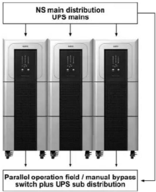
PROTECT C. 6000 (S) and C. 10000 (S) was developed for the parallel operation in n+x technology ("n" stands for the number of necessary appliances for load supply, "x" stands for the redundancy level). Up to three appliances of the same type can be connected in parallel to raise the output power and/or to receive a higher availability.
flowchart
graph TD
    A["NS main distribution UPS mains"] --> B["Three stations"]
    B --> C["Parallel operation field / manual bypass switch plus UPS sub distribution"]
    C --> D["Output"]
The following constellations are possible according to the n+x technology:
| 1 + 0 | Use of 1 unit max. 6 or 1 | 10 kVA No redundancy | |
| 1 + 1 | Use of 2 units max. 6 or | 10 kVA Single redundancy | ( max. configuration level) |
| 1 + 2 | Use of 3 units max. 6 or | 10 kVA Double redundancy | |
| 2 + 0 | Use of 2 units max. 12 or | 20 kVA No redundancy | |
| 2 + 1 | Use of 3 units max. 12 or | 20 kVA Single redundancy (max. configuration level) | |
| 3 + 0 | Use of 3 units max. 18 or | 30 kVA No redundancy (max. configuration level) |
The active redundant parallel operation will switch automatically to the increase power mode if more power is required at the output of the UPS. This implements that the redundancy level decreases or will diminish completely. On the other hand the level of redundancy of the UPS will increase if the power consumption on the output decreases.
The distribution generally is realised in the low voltage main distribution (LVMD) where the external and the following sub distribution for connected load circuits takes place. Such parallel control panels in wall cabinets including an external HU as well as input and output control panel can also be ordered via AEG Power Supply System and their partners.
9.2 Setup / connection of the parallel operation field
The mains connection of each UPS is realised analogue to the description in chapter 5.

For the single phase mains connection for each UPS the same phase has to be used, i.e. all UPS have to use either L1 or L2 or L3 (no mix!). The supply of the multi pole central external manual bypass has to be realised with this phase.
The UPS outlets are connected via separator with the parallel operation bus-bar. At this point the instructions of chapter 5 are to follow.
The following applies for output and input lines of the UPS: The difference in length of the lines with a line length of up to 20 m may not vary more the 20% and with more than 20 m not more than 10%.
The default bridge between “JP1” and “JP2” in the control panel of every UPS has to be removed. The distribution of the output has to be executed according the instructions of chapter 5. Please take care of the exact labelling of the elements to prevent any operation error. The communication between the parallel connected units is realised with the 25 pole parallel operation line that comes with the UPS.
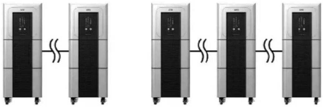
The first step is to remove the parallel port cover (Pos 5, page 83/84) and to connect the UPS with each other with the parallel operation line. With two units use one, with three units use two parallel operation lines (don't build up a ring structure!)
(Communication) parallel operation interconnection
... with 2 units: ... with 3 units:
natural_image
Four identical industrial refrigeration units connected in series with coiled lines, no visible text or symbols.After connecting the units with the parallel operation line close the parallel operation cover again. Turn the cover by 180^ such that the notches show to the bottom.
The hardware installation is completed now.
9.3 Operation in parallel compound
The activation process is not complicated and no knowledge is required. Just follow the instructions in chapter 6. Should you have ordered the parallel operation panel from AEG Power Solutions follow the instructions of the separate operation manual. The display of the UPS operates analogue to the description of a single unit in chapter 8.
9.3.1 Activation
- Check that all connection have been made according to the installation guide.
- Check that all loads have been switched off.
-
Check that the manual bypass switch "Maintenance Switch" (Pos. 2, page 83/84) on the back of the UPS is in "Bypass" position and that all mains input circuit breaker (Pos. 3, page 83/84) on the back of the UPS are in position "OFF".
-
Check that the central manual bypass is in position „bypass” i.e. that the mains supplies the loads bus-bar.
- Connect the separator of the output of each UPS, i.e. connect every output of a UPS with the parallel operation bus-bar.
- Put in the prefuse of the low voltage main distribution field (there, where the UPS systems are connected on the input side with the mains), resp. switch on the corresponding line fuse.

The load supply now takes place via the central external manual bypass. The parallel operation bus-bar is supplied by the integrated bypass of each UPS. Parallel operation bus-bar and load bus-bar are not yet connected at this time!
- Press the mains input circuit breaker one by one on each UPS (Pos. 3, page 83/84). Bring it to the "ON" position.
- The manual bypass switch „Maintenance Switch“ (Pos. 2, page 83/84) on the back of each UPS has to be brought into the “UPS” position. Fix on each UPS the cover with the four previously removed screws.

The power supply of the parallel bus-bar now is realised via the integrated electronic bypass equipment of the UPS. Check the operation state on the display of each UPS = bypass (chapter 6.1.3.).
- Activate the central external manual bypass now: Change from position "bypass" to "UPS operation" i.e. connects the load bus-bar with the UPS parallel operation bus-bar.

This takes place without interruption, if you are using a manual bypass switch with overlapping contacts.
- Now switch on the inverters of each UPS. To do this, press and hold the UPS ON switch one by one for about 2 seconds.

When being powered on, the UPS will perform self-diagnosis, the Load/Battery level LEDs will be turned on and then off one after another in ascending order. After synchronising all inverters successfully the LED “Inverter” will go on after some seconds on each UPS, with the UPS in parallel normal mode. The loads bus-bar is supplied by the UPS.

Protect the central external manual bypass switch against accidental activation. Never activate the switch when the UPS is in inverter mode.
- When all displays are lit as described, switch on your loads one after the other. Note the maximum permitted UPS load when doing this. Also keep in mind the spare power, if an active redundancy is required.
9.3.2 Modification in parallel compound
For adding another UPS to the parallel compound or for removing a UPS from the parallel compound, the UPS system has to be brought into the Bypass operation mode.

Load supplied through mains!
(No UPS protection during these steps).
First switch the inverter of all the UPS system one by one off (press the "OFF" switch). All UPS systems are working in the SBS / bypass mode. Check the state on all displays. Activate the integrated bypass (Pos. 2, page 83/84) on the back of the UPS. For this remove the four screws of the cover on the rear.
Bring the mains input circuit breaker of each UPS into the "OFF" position. With the central external manual bypass the
bypass for the loads is done, i.e. activation of the manual bypass operation, suspension of the supply for the load by the UPS bus-bar.
The clearance of the voltage of each UPS is realised in the low voltage distribution. Now the expansion resp. the reduction of the parallel compound can be executed now. Watch out for the bridge between “JP1” and JP2” and the parallel operation line. The activation follows the steps in chapter 9.3.1.

For deactivating the UPS in the parallel compound just press the „OFF“ switch twice behind each other. Like this the UPS-Systems can be removed from the parallel operation bus-bar.
10 Maintenance
The PROTECT C. consists of advanced and resistant components. To guarantee a continuous and high availability it is recommended to check the unit (especially the batteries and the fans) in regular intervals (at least every 6 months).
CAUTION:
Before going through the next step disconnect the PROTECT C. from the mains.
10.1 Charging the Battery
The battery is automatically charged when the mains is present, irrespective of the operating mode. This is signalled by the "charge" symbol lighting up (see also chapter 4.4.2, page 82).
The complete charging time of the battery after a length discharge period depends, above all, on the number of additional external battery units.
Charging time up to 90% of rated capacity
| Only with internal UPS battery approx. 7 hours | |
| One additional battery unit | approx. 11 hours |
| Two additional battery units | approx. 16 hours |
| Three additional battery units | approx. 24 hours |
10.2 Maintenance
The following maintenance work should be performed:
| Task | Interval | Described in |
| Visual check | 6 months | Chapter 10.2.1 |
| Battery/fan check | 6 months | Chapters 10.2.2 / 10.2.3 |
10.2.1 Visual Check
When visually checking the unit, check whether:
◆ there is any mechanical damage or foreign bodies can be found in the system,
◆ any conductive dirt or dust has accumulated in the unit,
◆ accumulation of dust affects heat supply and dissipation.
CAUTION:
PROTECT C. must be disconnected from the power supply prior to carrying out the following work.
If large quantities of dust have accumulated, the unit should, as a precaution, be cleaned with dry compressed air, in order to ensure adequate heat dissipation.
The intervals at which visual checks should be performed are largely determined by the site conditions.
10.2.2 Checking the Battery
Progressive ageing of the battery system can be detected by regular capacity checks. Every 6 months, perform measurements to compare the achievable standby times, e.g. by simulating a mains failure. In this case, the load should always have approximately the same capacity demand. Please contact our hotline if the time drops drastically compared to the previous measurement (see page 62).
10.2.3 Fan Checking
Regularly check the fans for dust build-up and noticeably untypical noise development. Clean the intake openings if they are blocked. Contact our hotline if a fan is running unusually loud or irregularly (see page 62).
11 Storage, Dismantling and Disposal
11.1 Storage

Long storage times without charging or discharging the battery at regular intervals may lead to permanent damage of the battery.
If the battery is stored at room temperature (20°C to 30°C) it will automatically discharge at a rate of 3 - 6% per month due to internal reactions. Storing the battery at temperatures above room temperature should be avoided. A high storage temperature also means greater battery self-discharge.
Batteries that are stored at room temperature should be recharged every six months to maintain their full capacity and service life.

Connect PROTECT C. to the mains before putting it into storage, in order to make sure that the battery is fully charged. The charging time should at least match the time specified in chapter 9.2. Charging the Battery on page 112.
11.2 Dismantling
The system is dismantled in reverse order of the installation instructions.
11.3 Disposal
In the interest of environmental protection and recycling, please dispose of the individual system components in accordance with the regulations and legal guidelines when permanently taking the system out of operation. Please consider that infringements to these regulations may result in civil or criminal prosecution.
12 Glossary
12.1 Technical terms
Appliance protection Surge technology term
The conventional mains surge protection consists of an mains earthwire (class B), an overvoltage protection (class C) and an appliance protection (class D) – see also e.g. under http://www.phoenixcontact.de (topic „TRABTECH“)
Class D see appliance protection
DC/DC Booster Circuit technology to boost the direct current on a higher voltage level
IGBT I _nsulated Gate Bipolar Transistor
The latest design of high-performance transistors with minimum control power requirement (MOSFET structure) and minimum losses on the output side (structure of a bipolar transistor)
LED L _ight Emitting Diode
Electronic semiconductor component, commonly called light diode. Used for optical signalling.
PFC Power Factor Correction _
Circuit technology to minimize circuit backfeed (important for non linear loads)
PWM P _ulse Width Modulation
Here: Circuit technology for generating a sinusoidal voltage of the highest quality from an existing DC voltage
SNMP Simple Network Management Protocol
common protocol in networks to manage / control appliances
VFD Output V _oltage and Frequency Dependent
from mains supply. The UPS output depends of mains voltage and frequency variations. Former notation: OFFLINE
VI Output V _oltage Independent from mains
supply. The UPS output is independent of mains voltage and frequency variations. The mains voltage however is rectified by electronic / passive voltage regulators. Former notation: LINE-INTERACTIVE
VFI Output V _oltage and Frequency Independent
from mains supply. The UPS output is independent of mains voltage and frequency variations. Former notation: ONLINE
Guarantee certificate
Type: ....
Serial-no.:
Date of purchase: ....
Trading stamp / Signature
Specifications are subject to change without notice.
AEG
Power Solutions
Operating Instructions UPS
BAL 8000020472_01 EN


- AEG
- PROTECT C.
- Notes on these Operating Instructions
- Duty to Provide Information
- Please read these instructions carefully prior to commissioning!
- Validity
- Warranty and Liability
- Handling
- Hotline
- Table of Contents
- General Information
- Technology
- System Description
- Technical Data
- Battery
- Guidelines
- Warning:
- Safety
- General Safety Instructions
- Danger!
- Attention!
- Information!
- Accident prevention regulations
- Qualified personal
- Safety Instructions for PROTECT C.
- Danger! Risk of burning!
- Danger! Electric shocks!
- Only authorised persons are allowed in the vicinity of the batteries!
- Danger! Explosive!
- Certification
- Declaration of Conformity
- Set-Up and Operation
- Unpacking and Inspection
- Check the delivery is complete:
- Delivery of external battery modules includes:
- Transportation to the site
- Point of Installation
- Overview: Connections, Operating / Display Elements
- Front view
- Display
- Explanations
- Rear view (connections):
- Comments:
- Commissioning
- Attention
- Protection for the personnel
- Mains connection (general)
- Checklist for connectors
- Connection diameter and protection
- One phase mains connector
- Preparation for the one phase mains connector
- Connection of the one phase mains connector
- Preparation for the load connection
- Connection of the loads
- External Battery Expansions
- Mechanic blocking of the PROTEC C.
- Electrical Start-Up
- Turn on the PROTECT C. to the mains
- i
- Behaviour when switching off:
- Operating
- Normal Operation
- Battery Operation / Autonomy Operation
- Bypass Operation
- Manual bypass
- Unit Overload
- Interfaces and communication
- Computer interfaces RS232
- Communication Slot
- Shutdown and UPS management software
- Signalling and Error Correction
- Signalling
- Table overview of LED display / alarm signals
- Continuation overview of LED display / alarm signals
- Fault Diagnosis / Fault Rectification
- Parallel operation
- Functionality
- Setup / connection of the parallel operation field
- (Communication) parallel operation interconnection
- Operation in parallel compound
- Activation
- Modification in parallel compound
- Maintenance
- CAUTION:
- Charging the Battery
- Maintenance
- Visual Check
- Checking the Battery
- Fan Checking
- Storage, Dismantling and Disposal
- Storage
- Dismantling
- Disposal
- Glossary
- Technical terms
- Guarantee certificate
- Power Solutions
Brand : AEG
Model : Protect C.6000 S
Category : Uninterruptible power supply