
Pro Mixer DJX750 - Mixer BEHRINGER - Free user manual and instructions
Find the device manual for free Pro Mixer DJX750 BEHRINGER in PDF.


| Product Type | DJ Mixer |
| Brand | Behringer |
| Model | Pro Mixer DJX750 |
| Channels | 4 |
| Inputs | 4x RCA (line), 2x XLR (mic), 2x Phono (turntable) |
| Outputs | 2x XLR (main), 2x RCA (booth), 1x 1/4" (headphones) |
| Crossfader | Replaceable, adjustable curve |
| EQ | 3-band per channel (Hi, Mid, Low) |
| Effects | Built-in 24-bit digital effects (delay, echo, reverb) |
| Talkover | Yes, with adjustable threshold |
| Sampler | None |
| Dimensions (W x D x H) | 320 mm x 280 mm x 100 mm |
| Weight | 3.5 kg |
| Power Supply | 15V DC, 1.5A (external adapter) |
| Power Consumption | 15 W |
| Frequency Response | 20 Hz – 20 kHz |
| Signal-to-Noise Ratio | >90 dB |
| Total Harmonic Distortion | <0.05% |
| Headphone Output | 1/4" stereo, 100 mW into 32 Ω |
| Compatible Software | Traktor, Serato, Virtual DJ (via in-box cable) |
| Construction | Aluminum front panel, steel chassis |
| Cleaning | Use a dry, lint-free cloth; avoid solvents |
| Safety | Class II, EMC compliant |
| Spare Parts / Repairability | Crossfader and knobs available as spares |
Frequently Asked Questions - Pro Mixer DJX750 BEHRINGER
User questions about Pro Mixer DJX750 BEHRINGER
0 question about this device. Answer the ones you know or ask your own.
Ask a new question about this device
Download the instructions for your Mixer in PDF format for free! Find your manual Pro Mixer DJX750 - BEHRINGER and take your electronic device back in hand. On this page are published all the documents necessary for the use of your device. Pro Mixer DJX750 by BEHRINGER.
USER MANUAL Pro Mixer DJX750 BEHRINGER
of the BEHRINGER PRO MIXER DJX750 has put you at the forefront of today's trends in DJ mixing consoles. Numerous features, such as beat counter, insert loop and digital effects processor, enable you to work in completely new and creative ways. The DJX750 is a mixer for professional use, it is extremely easy to operate and it helps you give free rein to your creativity. Time is tight and if you don't want to be left in the dust, you'd better get moving. To help you along, we have developed an excellent DJ mixing console with the most popular new features and technologies. It is perfectly suited for use in dance clubs or for DJ systems and is sure to deliver tons of pure fun. Be honest: who really likes to read manuals? We know you want to get started right away, but it is only after reading these instructions that you will fully understand and be able to properly use all the features your DJX750 has to offer. Take the time to read everything through!
This manual is available in English, German, French, Spanish, Italian, Russian, Polish, Dutch, Finnish, Swedish, Danish, Portuguese, Greek, Japanese and Chinese. There may also be more current versions of this document. Download them by going to the appropriate product page at:
www.behringer.com
A50-95630-08001
PRO MIXER DJX750
Professional 5-Channel DJ Mixer with Advanced Digital Effects and BPM Counter
Table of Contents
Safety Instructions 2
Control elements 3
Stereo channels 1 to 4 ....3
Microphone channel 4
MONITOR section 4
MASTER section 4
Crossfader section 4
XPQ 3D surround effect ....5
Auto BPM counter 5
Internal effects processor ....5
Connections 6
Rear panel connectors 6
Initial operation 7
Shipment 7
Online Registration 8
Specifications 8
Warranty 9
Federal Communications Commission compliance information .... 10

Safety Instructions
Caution
This symbol, wherever it appears, alerts you to the presence of uninsulated dangerous voltage inside the enclosure - voltage that may be sufficient to constitute a risk of shock.

Caution
This symbol, wherever it appears, alerts you to important operating and maintenance instructions in the accompanying literature. Please read the manual.

Caution
To reduce the risk of electric shock, do not remove the top cover (or the rear section). No user serviceable parts inside. Refer servicing to qualified personnel.
To reduce the risk of fire or electric shock, do not expose this appliance to rain and moisture. The apparatus shall not be exposed to dripping or splashing liquids and no objects filled with liquids, such as vases, shall be placed on the apparatus.
These service instructions are for use by qualified service personnel only. To reduce the risk of electric shock do not perform any servicing other than that contained in the operation instructions. Repairs have to be performed by qualified service personnel.

Caution
1 Read these instructions.
2 Keep these instructions.
3 Heed all warnings.
4 Follow all instructions.
5 Do not use this apparatus near water.
6 Clean only with dry cloth.
7 Do not block any ventilation openings. Install in accordance with the manufacturer's instructions.
8 Do not install near any heat sources such as radiators, heat registers, stoves, or other apparatus (including amplifiers) that produce heat.
Do not defeat the safety purpose of the polarized or grounding-type plug. A polarized plug has two blades with one wider than the other. A grounding-type plug has two blades and a third grounding prong. The wide blade or third prong are provided for your safety. If the provided plug does not fit into your outlet, consult an electrician for replacement of the obsolete outlet.
10 Place the power cord so that it is protected from being walked on and sharp edges. Be sure that the power cord is protected particularly at plugs, convenience receptacles and the point where it exits from the apparatus.
11 The apparatus shall be connected to a MAINS socket outlet with a protective earthing connection.
12 Where the MAINS plug or an appliance coupler is used as the disconnect device, the disconnect device shall remain readily operable.
13 Only use attachments/accessories specified by the manufacturer.
14 Use only with the cart, stand, tripod, bracket, or table specified by the manufacturer, or sold with the apparatus. When a cart is used, use caution when moving the cart/apparatus combination to avoid injury from tip-over.
15 Unplug this apparatus during lightning storms or when unused for long periods of time.
16 Refer all servicing to qualified service personnel. Servicing is required when the apparatus has been damaged in any way, such as power supply cord or plug is damaged, liquid has been spilled or objects have fallen into the apparatus, the apparatus has been exposed to rain or moisture, does not operate normally, or has been dropped.

Control elements
Stereo channels 1 to 4
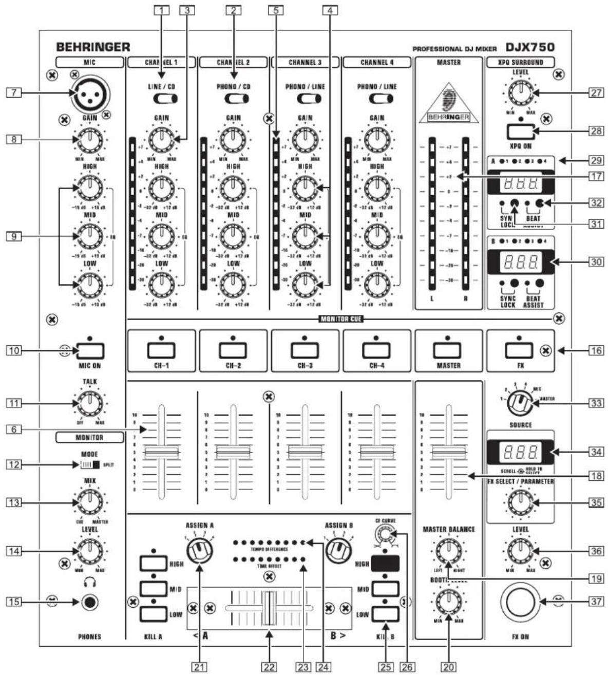
1 Use the LINE/CD switch to select the input signal for channel 1. Unlike other channels, channel 1 features two line inputs.
2 You determine the input signals for the channels 2 to 4 with the PHONO/CD i. e. PHONO/LINE switch (channels 3 and 4). "Phono" is intended for connecting a turntable. "Line" i. e. "CD" must be selected for all other signal sources (e. g. CD or MD players). The input sensitivity of the phono input can be switched to line level, allowing utmost flexibility (see [41]).
Never connect devices with line level to the highly sensitive phono inputs! The output level of phono pick-up systems is measured in millivolts, whereas CD players and tape decks have levels measured in volts, i.e. the level from line signals is up to 100 times higher than that of the phono inputs.
3 The GAIN control in the CHANNEL section is used to adjust the level of the input signal. The level meter 5 reads the input level.
4 Each of the input channels features a 3-band equalizer (HI, MID and LOW) with kill characteristic. Thus, the signal can be attenuated to a much greater extent (-32 dB) than it can be raised (+12 dB). This function can be very useful when, for example, fading a frequency range out of a music track.
◇ The overall level also depends on the EQ setting. Thus, you should adjust the equalizer before setting the input gain with the GAIN control.
5 The 10-digit LED chains display the signal level of the input signals.
6 Adjust the channel volume using the CHANNEL fader.
Microphone channel
7 The MIC IN connector is the balanced XLR input for your dynamic microphone.
8 Set the volume of the microphone signal with the GAIN control in the MIC section.
9 There is a 3-band equalizer (HI, MID and LOW, no kill characteristic) in the microphone section. This allows you to fine-tune your voice to adapt perfectly to your sound.
10 Activate the microphone channel using the MIC ON switch. The channel is active when the corresponding LED is lit.
[11] The DJX750 is equipped with a talkover function, which works very simply: if you speak into the microphone while a track is running, the volume of the music is automatically reduced, so that your voice is always “in front”. The TALK control allows you to determine how much the music volume is lowered (max. -24 dB). This function can come in handy when your own voice needs to be prominently heard, as in when making an announcement etc.
MONITOR section
The MONITOR signal is your headphones signal, allowing you to listen to music without affecting the MASTER output signal.
12 When the MODE switch is in the “Split” position, channel PFL is located on the left side of the headphones, while the MASTER signal is on the right side. In this case, the MIX control (see below) serves no function. While in “Stereo” mode, you can use the MIX control to alternate between MASTER signal and PFL.
13 When in “Stereo” mode, the MIX control lets you determine which signal can be heard via the headphones. When the control is turned to its left-most position (CUE), you hear the PFL signal only; when the control is turned to
its right-most position, you hear the MASTER signal only. Alternating the MIX control between the two end positions lets you dermine the relative ratio between the two signals in your headphones.
14 The Level control determines the volume of the headphones signal.
15 Connect you headphones using PHONES OUT stereo connector. Your headphones should have a minimum impedance of 32 Ohms.
16 To select the PFL signal for the headphones, use the MONITOR CUE keys (CH-1 to CH-4, MASTER, FX). You can also select multiple signal sources and listen to them simultaneously. LEDs on corresponding keys are lit when a channel is routed to the headphones.
MASTER section
17 The LEVEL METER displays the level of the MASTER signal.
18 The MASTER fader allows you to adjust the output volume at the MASTER output (see 44).
[19] The MASTER BALANCE control for the MASTER output is for setting the stereo image.
20 The BOOTH LEVEL control adjusts the output level of the BOOTH output (see 45).
Crossfader section
21 ASSIGN A and ASSIGN B selectors let you determine which input signals are routed to CROSSFADER sides A and B. You can also alternate between these two signals by using the CROSSFADER (see below).
22 The VCA controlled CROSSFADER is used to fade between the channels you have selected (see 21). Like the channel faders, the crossfader section is equipped with a professional 45-mm fader.
23 The TIME OFFSET LED indicates the synchronisation of tracks (see chapter 2.7).
[24] The TEMPO DIFFERENCE LED displays tempo differences between the tracks (see chapter 2.7).
25 A 3-band kill switch is available for use with both the left and the right side of the crossfader (KILL A and KILL B respectively). Kill switches are used to lower three separate frequency ranges (LOW, MID and HIGH) up to -32 dB. When using the kill switch, the equalizer of ordinary DJ mixers usually loses its functionality. Not the case with the DJX750: the EQs can be used to achieve an even more pronounced lowering of a particular frequency range.
26 The CF CURVE control lets you alter the control characteristic of the crossfader between linear and logarithmic in an infinite number of steps. When set to linear, the crossfader
engages directly proportionally to the fader's incremental movement. When set to logarithmic, the fader's movement yields higher volume increases as the fader moves farther along its range of motion.
XPQ 3D surround effect
The XPQ 3D surround function is a built-in effect that puts the finishing touch to your music and turns every gig into a real experience. The widening of the stereo base makes for a livelier, more transparent sound. You can determine the intensity of the effect by using the SURROUND control [27], while the XPQ ON switch [28] turns the XPQ effect on (the respective LED is lit).
Auto BPM counter
The integrated auto BPM counter is an extremely useful feature. It ensures smooth transition from one track to the next, taking a lot of the guesswork out. It can calculate the various tempos of tracks in bpm (beats per minute). Both BPM counter sections are identical and both show the BPM value of the two signals routed to the crossfader. The LEDs located above the DISPLAYs 1 - 4 [29] indicate which of the four input channels are routed to the respective BPM counter.
The tempo of the track assigned by using the ASSIGN A or ASSIGN B keys is shown in the respective Display [30] . Several tempo changes in one track would produce a constant display of various BPM values and thus lead to unnecessary confusion. That's why the beat counter sections each have a SYNC LOCK button [31] that can be used during the song to limit the range of possible tempo values. This makes sense if the counter has already calculated a realistic value. You can do the same thing manually with the BEAT ASSIST button [32] . Pushing this button at least three times in sync with the song's tempo results in the calculated tempo appearing in the DISPLAY. The Beat Assist and SYNC LOCK buttons are each equipped with a LED. When you have limited the tempo of the tracks on both channels with the SYNC LOCK or BEAT ASSIST buttons, the difference in tempo from both channels is illustrated in the form of a nine-character message on the TEMPO DIFFERENCE-LED [24] . The extent of the difference in tempo is indicated by a corresponding swing to the right (signal A is slower) or to the left (signal B is slower). When the middle LED lights up, the tempi are the same. The TIME OFFSET LED [23] below that displays the signal A and B synchronisation. Should the middle LED light up, the tracks are synchronised. Should the display move to the left or right, the channels are not synchronised. The TEMPO DIFFERENCE and TIME OFFSET displays are only active if the tempi of both channels have been fixed in one of the ways described.
When no signal is present (or when the signal level is too low), the BPM display shows only dashes. When the signal is present but can not be identified, the display shows 160 BPM and then shows the said dashes. The beat counter then attempts to get another readout. Therefore, "160" BPM is no usable value; rather, it is simply an error message when the signal can not be analyzed.
To exit the SYNC LOCK or BEAT ASSIST modes, simply push the SYNC LOCK button once more on both channels.
Internal effects processor
Presets of the multi-effects processor
| Grp No. Effect Type | Adjustable Parameter | |||
| 1 | 0 Filter Sweep LP Frequency | |||
| 1 Filter Sweep BP Frequency | ||||
| 2 Filter Sweep HP Frequency | ||||
| 3 | Auto Filter (Envelope) | LP Sensitivity | ||
| 4 | Auto Filter (Envelope) | BP Sensitivity | ||
| 5 | Auto Filter (Envelope) | HP Sensitivity | ||
| 6 LFO | Filter LP LFO Rate | |||
| 7 LFO | Filter BP LFO Rate | |||
| 8 LFO | Filter HP LFO Rate | |||
| 2 | 0 Bitcrusher -- Depth | |||
| 3 | 0 Flanger Gate/Pan | LFO Rate | ||
| 1 Flanger | Standard (Full Res) | LFO Rate | ||
| 2 Flanger | Standard (Half Res) | LFO Rate | ||
| 3 Flanger Ultra | LFO Rate | |||
| 4 | 0 Delay | 1/1 | Delay Time (related to BPM) | |
| 1 Delay | 3/4 | Delay Time (related to BPM) | ||
| 2 Delay | 1/2 | Delay Time (related to BPM) | ||
| 5 | 0 Echo | 1/1 | Delay Time (related to BPM) | |
| 1 Echo | 3/4 | Delay Time (related to BPM) | ||
| 2 Echo | 1/2 | Delay Time (related to BPM) | ||
| 6 | 0 Reverb | Big Plate | Reverb Time (Decay) | |
| 1 Reverb | Small Chamber | Reverb Time (Decay) | ||
| 2 Reverb | Bright Room | Reverb Time (Decay) | ||
| 3 Reverb | Voice Widener | Tone | ||
| 4 Reverb/Delay | Big Plate + Delay | Delay Time (related to BPM) | ||
| 7 | 0 | Phase Shifter | 4 | LFO Rate |
| 1 Phase Shifter | Fall | LFO | Rate | |
| 2 Phase Shifter | Rise | LFO | Rate | |
| 8 | 0 Panning | Panning | LFO | Rate |
| 1 Panning | Tremolo | LFO | Rate | |
| 9 | 0 Sim/Dyn Ultrabass | Frequency | ||
| 1 Sim/Dyn Ultrafex | Frequency | |||
| 2 Sim/Dyn Voice Changer Distortion | ||||
The DJX750 features an internal digital effects processor into which you can feed your master signal, the signals of the input channels or the mic signal. The module provides a number of standard effects, such as reverb, delay and echo, as well as various filter and modulation effects.
To select the signal to be processed, use the SOURCE selector • 33.
Turn the PROGRAM control 35 to select an effect. The corresponding program number appears on the PROGRAM display 34.
Press and hold the PROGRAM control for about 2 seconds to load the selected preset.
When the new effect has been loaded, turn the PROGRAM • control [35] to change the effect's parameters. The parameter value is shown on the display.
◇ View the table (column "Ajustable Parameter") to see which parameter of the selected effect can be modified.
The parameter values of the delay and echo effects are displayed in BPM (beats per minute). The selectable range is from 80 to 160 BPM. The display only shows two digits and so values of 100 and above are represented with a dot behind the number (for example, 120 BPM is displayed as "20.").
Use the LEVEL control 36 to determine the volume level of the effect signal.
Activate the effect signal by pressing the FX ON switch 37. Press the PROGRAM control one more time to use it for selecting effects again.
Connections
Rear panel connectors
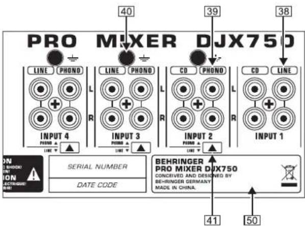
38 These are the LINE i. e. CD inputs to connect a tape deck, CD or MD player etc. Unlike other channels, channel 1 features two line inputs.
39 The PHONO inputs for channels 2 to 4 are for connecting a turntable.
40 The connectors ground the turntables.
41 With the PHONO/LINE switch it is possible to switch the input sensitivity of the PHONO inputs 2 to 4 to line level. This allows you to connect a tape deck or a CD player to the PHONO inputs.
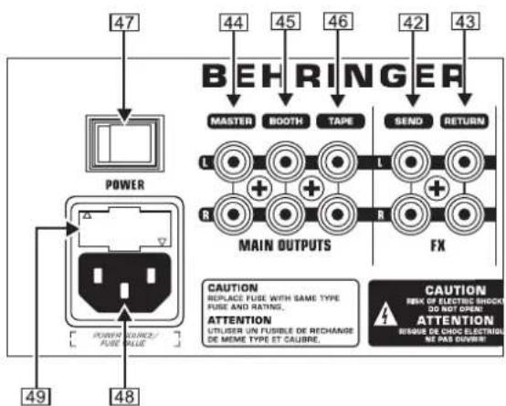
42 The DJX750 features an integrated effects loop for the connection of an external effects device. The MONITOR signal is taken at the SEND output and routed, for example, to a reverb processor. Thus, the signal at the SEND connector is identical to the headphones signal and is selected with the MONITOR CUE buttons 16.
43 The externally processed signal is added to the MASTER output signal via the RETURN connectors. The effect signal volume may only be adjusted at the output control of the effects device itself.
44 The MASTER output is for connecting to an amplifier and can be adjusted with the MASTER fader 18.
Always turn the power amps on last to avoid inrush currents that can easily damage your speakers. And, to avoid sudden and unpleasant surprises for your ears, make sure there is no signal at the DJX750 before turning on the power amps. To be sure, slide all the faders to the bottom and switch all controls to the zero position.
45 The BOOTH output gives you an additional option of connecting an amplifier in order to, for example, feed the signal into your monitors or to bring sound to an extra area. The BOOTH output level is regulated by using the BOOTH LEVEL control 20 of the MASTER section.
46 Using the TAPE output you can record your music by connecting devices such as tape decks, DAT recorders etc. Unlike the MASTER output, the output volume is fixed,
making it necessary for you to adjust the input level on the recording device.
47 The POWER switch powers the DJX750 on. You should always make sure that the POWER switch is in the "Off" position when initially connecting the unit to the mains.
Merely switching the unit off does not mean that it is fully disconnected from the mains. When not using the unit for prolonged periods of time, please unplug the unit's power cord from the power outlet.
48 This is the connector for the power cable. This is where the advantage of a sophisticated internal power supply can be seen: the pulse behaviour of each amplifying circuit is mainly determined by the voltage reserves available. Each mixing console is equipped with numerous operational amplifiers (op amps) to process line level signals. Due to limited output of their power supplies, many mixing consoles show signs of “stress” when subjected to heavy loads. But not your DJX750: the sound is always clear and transparent.
49 FUSE HOLDER / VOLTAGE SETTING. Before connecting the unit to the mains, ensure that the voltage setting matches your local voltage. Blown fuses should only be replaced by a fuse of the same type and rating. On some units, the fuses holder can be switched to one of two positions, i.e. 230 V and 120 V. Please note: should you desire to operate the unit outside Europe at 120 V, a higher fuse rating is required.
To disconnect power from main, pull out the main cord plug. When installing the product, ensure that the plug is easily accessible. If mounting in a rack, ensure that the mains can be easily disconnected by a plug or by an all-pole disconnect switch on or near the rack.
50 SERIAL NUMBER.
Initial operation
- Ensure adequate air supply and to avoid overheating do not place the unit near radiators etc.
Before you connect your unit to the mains, please make sure that your local voltage matches the voltage required by the unit.
The fuse holder on the mains connector has 3 triangular markings, with two of these triangles opposing each other. The unit is set to the operating voltage printed next to these markers and can be set to another voltage by turning the fuse holder by 180°.

Caution
Please note that when operating the unit at 120 V, a higher fuse rating is required. Please refer to the "Specifications" for details.
If you set the unit to a different mains voltage, be sure to use a fuse of the correct type and rating. Please refer to the “Specifications” for details.
◇ Blown fuses must be replaced by fuses of the correct rating! Please refer to the “Specifications” section for the applicable rating. Before you change the fuse, switch off the device and pull the plug to avoid electric shock or damage to the device.
The mains connection is made using the enclosed power cord and a standard IEC receptacle. It meets all international safety certification requirements.
Please make sure that all devices are properly grounded. For your own safety, never remove or disable the ground conductors from the devices or on the power cords. The unit must always be connected to the mains outlet with a protective grounding connection.
The sound quality may diminish within the range of powerful broadcasting stations and high-frequency sources. Increase the distance between the transmitter and the device and use shielded cables for all connections.
Shipment
Should your BEHRINGER product malfunction, it is our intention to have it repaired as quickly as possible. To arrange for warranty service, please contact the BEHRINGER retailer from whom the equipment was purchased. Should your BEHRINGER dealer not be located in your vicinity, you may directly contact one of our subsidiaries.
Corresponding contact information is included in the original equipment packaging (Global Contact Information/European Contact Information). Should your country not be listed, please contact the distributor nearest you. A list of distributors can be found in the support area of our website (http://www.behringer.com).
Registering your purchase and equipment with us helps us process your repair claims more quickly and efficiently.
Your product was carefully packed at the factory to ensure safe transport. Nevertheless, if the box is damaged inspect the unit immediately for signs of damage.
If the unit is damaged please do NOT return it to us, but notify your dealer and the shipping company immediately; otherwise, claims for damage or replacement may not be granted.
◇ Always use the original box to prevent damage during storage or transport.
Make sure that children cannot play unsupervised with the unit or its packaging.
Online Registration
Please register your new BEHRINGER equipment right after your purchase by visiting http://www.behringer.com and read the terms and conditions of our warranty carefully.
Thank you for your cooperation!
Specifications
Audio Inputs
| Mic 40 dB Gain, XLR, electronically balanced input stage |
| Phono in 40 dB Gain, unbalanced input |
| Line in 0 dB Gain, unbalanced inputs |
| CD in 0 dB Gain, unbalanced inputs |
| Return 0 dB Gain, unbalanced input |
Audio Outputs
| Master max. +21 dBu |
| Booth max. +21 dBu |
| Tape typ. 0 dBu |
| Send typ. 0 dBu |
| Phones Out max. 180 mW @ 75 W / 1% THD |
Equalizer
| Stereo Low +12 dB/-32 dB @ 50 Hz | |
| Stereo Mid +12 dB/-32 dB @ 1.2 kHz | |
| Stereo High +12 dB/-32 dB @ 10 kHz | |
| Mic Low +15 dB/-15 dB @ 80 Hz | |
| Mic Mid +15 dB/-15 dB @ 2.5 kHz | |
| Mic High | +15 dB/-15 dB @ 12 kHz |
| Kill Low | -54 dB @ 50 Hz |
| Kill Mid | -44 dB @ 1 kHz |
| Kill High | -26 dB @ 10 kHz |
Digital Effects Processor
| DSP | 24-bit Texas Instruments |
| A/D-D/A converter | 24-bit Sigma-Delta, 64/128-times oversampling |
| Sampling rate | 46.875 kHz |
System specifications
| Signal-to-noise ratio | >80 dB (Line) |
| Crosstalk >70 dB (Line) | |
| Distortion (THD) | < 0.03% |
| Frequency response | 10 Hz - 55 kHz, +0/-3 dB |
Power supply
| Power consumption | 32 W |
| Mains connection | Standard IEC receptacle |
Mains voltages/Fuses
| 100 - 120 V~, 50/60 Hz | T 1 A H |
| 220 - 230 V~, 50/60 Hz | T 500 mA H |
Dimensions/Weight
| Dimensions (H x W x D) | approx. 104.3 x 320 x 370.8 mm |
| approx. 4110 " x 12120 " x 14 3/5" | |
| Weight | approx. 3.9 kg |
| approx. (8 1/2 lbs) |
BEHRINGER is constantly striving to maintain the highest professional standards. As a result of these efforts, modifications may be made from time to time to existing products without prior notice. Specifications and appearance may differ from those listed or illustrated.
Warranty
Other warranty rights and national law§ 1
This warranty does not exclude or limit the buyer's statutory rights provided by national law, in particular, any such rights against the seller that arise from a legally effective purchase contract.
② The warranty regulations mentioned herein are applicable unless they constitute an infringement of national warranty law.
Online registration§ 2
Please do remember to register your new BEHRINGER equipment right after your purchase by visiting http://www.behringer.com and kindly read the terms and conditions of our warranty carefully. Registering your purchase and equipment with us helps us process your repair claims quicker and more efficiently. Thank you for your cooperation!
Warranty§ 3
1 BEHRINGER (BEHRINGER International GmbH including all BEHRINGER subsidiaries, except BEHRINGER Japan) warrants the mechanical and electronic components of this product to be free of defects in material and workmanship for a period of one (1) year from the original date of purchase, in accordance with the warranty regulations described below. If the product shows any defects within the specified warranty period that are not excluded from this warranty as described under § 5, BEHRINGER shall, at its discretion, either replace or repair the product using suitable new or reconditioned parts. In the case that other parts are used which constitute an improvement, BEHRINGER may, at its discretion, charge the customer for the additional cost of these parts.
② If the warranty claim proves to be justified, the product will be returned to the user freight prepaid.
③ Warranty claims other than those indicated above are expressly excluded.
Return authorization number§ 4
To obtain warranty service, the buyer (or his authorized dealer) must call BEHRINGER during normal business hours BEFORE returning the product. All inquiries must be accompanied by a description of the problem. BEHRINGER will then issue a return authorization number.
② Subsequently, the product must be returned in its original shipping carton, together with the return authorization number to the address indicated by BEHRINGER.
③ Shipments without freight prepaid will not be accepted.
Warranty regulations§ 5
1 Warranty services will be furnished only if the product is accompanied by a copy of the original retail dealer's invoice. Any product deemed eligible for repair or replacement under the terms of this warranty will be repaired or replaced.
② If the product needs to be modified or adapted in order to comply with applicable technical or safety standards on a national or local level, in any country which is not the country for which the product was originally developed and manufactured, this modification/adaptation shall not be considered a defect in materials or workmanship. The warranty does not cover any such modification/adaptation, irrespective of whether it was carried out properly or not. Under the terms of this warranty, BEHRINGER shall not be held responsible for any cost resulting from such a modification/adaptation.
3 Free inspections and maintenance/repair work are expressly excluded from this warranty, in particular, if caused by improper handling of the product by the user. This also applies to defects caused by normal wear and tear, in particular, of faders, crossfaders, potentiometers, keys/buttons, tubes, guitar strings, illuminants and similar parts.
4 Damage/defects caused by the following conditions are not covered by this warranty:
improper handling, neglect or failure to operate the unit in compliance with the instructions given in BEHRINGER user or service manuals; connection or operation of the unit in any way that does not comply with the technical or safety regulations applicable in the country where the product is used;
damage/defects caused by force majeure or any other condition that is beyond the control of BEHRINGER.
5 Any repair or opening of the unit carried out by unauthorized personnel (user included) will void the warranty.
[6] If an inspection of the product by BEHRINGER shows that the defect in question is not covered by the warranty, the inspection costs are payable by the customer.
7 Products which do not meet the terms of this warranty will be repaired exclusively at the buyer's expense. BEHRINGER will inform the buyer of any such circumstance. If the buyer fails to submit a written repair order within 6 weeks after notification, BEHRINGER will return the unit C.O.D. with a separate invoice for freight and packing. Such costs will also be invoiced separately when the buyer has sent in a written repair order.
Warranty transferability§ 6
This warranty is extended exclusively to the original buyer (customer of retail dealer) and is not transferable to anyone who may subsequently purchase this product. No other person (retail dealer, etc.) shall be entitled to give any warranty promise on behalf of BEHRINGER.
Claim for damage§ 7
Failure of BEHRINGER to provide proper warranty service shall not entitle the buyer to claim (consequential) damages. In no event shall the liability of BEHRINGER exceed the invoiced value of the product.
Federal Communications Commission compliance information

BEHRINGER
PRO MIXER DJX750
Responsible party name: BEHRINGER USA, Inc.
Address: 18912 North Creek Parkway, Suite 200 Bothell, WA 98011, USA
Phone/Fax No.: Phone: +1 425 672 0816 Fax: +1 425 673 7647
hereby declares that the product
PRO MIXER DJX750
complies with the FCC rules as mentioned in the following paragraph:
This equipment has been tested and found to comply with the limits for a Class B digital device, pursuant to part 15 of the FCC Rules. These limits are designed to provide reasonable protection against harmful interference in a residential installation. This equipment generates, uses and can radiate radio frequency energy and, if not installed and used in accordance with the instructions, may cause harmful interference to radio communications. However, there is no guarantee that interference will not occur in a particular installation. If this equipment does cause harmful interference to radio or television reception, which can be determined by turning the equipment off and on, the user is encouraged to try to correct the interference by one or more of the following measures:
- Reorient or relocate the receiving antenna.
- Increase the separation between the equipment and receiver.
- Connect the equipment into an outlet on a circuit different from that to which the receiver is connected.
- Consult the dealer or an experienced radio/TV technician for help.
This device complies with Part 15 of the FCC rules. Operation is subject to the following two conditions:
(1) this device may not cause harmful interference, and
(2) this device must accept any interference received, including interference that may cause undesired operation.
Important information:
Changes or modifications to the equipment not expressly approved by BEHRINGER USA can void the user's authority to use the equipment.
Technical specifications and appearance are subject to change without notice. The information contained herein is correct at the time of printing. All trademarks (except BEHRINGER, the BEHRINGER logo, JUST LISTEN and PRO MIXER) mentioned belong to their respective owners, and such use neither constitutes a claim of the trademarks by BEHRINGER nor affiliation of the trademark owners with BEHRINGER. BEHRINGER accepts no liability for any loss which may be suffered by any person who relies either wholly or in part upon any description, photograph or statement contained herein. Colors and specifications may vary slightly from product. Our products are sold through authorized dealers only. Distributors and dealers are not agents of BEHRINGER and have absolutely no authority to bind BEHRINGER by any express or implied undertaking or representation.
This manual is copyrighted. No part of this manual may be reproduced or transmitted in any form or by any means, electronic or mechanical, including photocopying and recording of any kind, for any purpose, without the express written permission of BEHRINGER International GmbH.
ALL RIGHTS RESERVED.
© 2008 BEHRINGER International GmbH, Hanns-Martin-Schleyer-Str. 36-38, 47877 Willich, Germany. Tel. +49 2154 9206 0, Fax +49 2154 9206 4903

This manual is available in English, German, French, Spanish, Italian, Russian, Polish, Dutch, Finnish, Swedish, Danish, Portuguese, Greek, Japanese and Chinese. There may also be more current versions of this document. Download them by going to the appropriate product page at:
www.behringer.com


- PRO MIXER DJX750
- Professional 5-Channel DJ Mixer with Advanced Digital Effects and BPM Counter
- Table of Contents
- Safety Instructions
- Caution
- Control elements
- Stereo channels 1 to 4
- Microphone channel
- MONITOR section
- MASTER section
- Crossfader section
- XPQ 3D surround effect
- Auto BPM counter
- Internal effects processor
- Connections
- Rear panel connectors
- Initial operation
- Shipment
- Online Registration
- Specifications
- Warranty
- Other warranty rights and national law§ 1
- Online registration§ 2
- Warranty§ 3
- Return authorization number§ 4
- Warranty regulations§ 5
- Warranty transferability§ 6
- Claim for damage§ 7
- Federal Communications Commission compliance information
- Important information:
Brand : BEHRINGER
Model : Pro Mixer DJX750
Category : Mixer