
U-Control UMA25S - MIDI Keyboard BEHRINGER - Free user manual and instructions
Find the device manual for free U-Control UMA25S BEHRINGER in PDF.


| Product Type | USB MIDI Keyboard Controller |
| Number of Keys | 25 velocity-sensitive keys |
| Assignable Controls | Rotary encoders, faders, transport buttons, pitch and modulation wheels |
| Connectivity | USB Type-B for MIDI and power, sustain pedal input (1/4" TRS) |
| Power Supply | USB bus-powered (5V DC via USB) |
| Dimensions (W x D x H) | 18.6 x 7.9 x 2.8 inches (472 x 200 x 70 mm) |
| Weight | 3.1 lbs (1.4 kg) |
| Compatibility | Windows (7 or later) and macOS (10.7 or later), class-compliant (no driver needed) |
| Included Software | Tracktion DAW and additional virtual instruments |
| Maintenance | Wipe with a soft, dry cloth; avoid moisture and solvents |
| Safety | Do not expose to liquids or extreme temperatures; unplug during storms |
| Spare Parts & Repairability | Contact Behringer support for replacement parts; user-serviceable only for USB cable |
| General Information | Compact design for mobile production; includes MIDI over USB and standard MIDI via adapter (not included) |
Frequently Asked Questions - U-Control UMA25S BEHRINGER
User questions about U-Control UMA25S BEHRINGER
0 question about this device. Answer the ones you know or ask your own.
Ask a new question about this device
Download the instructions for your MIDI Keyboard in PDF format for free! Find your manual U-Control UMA25S - BEHRINGER and take your electronic device back in hand. On this page are published all the documents necessary for the use of your device. U-Control UMA25S by BEHRINGER.
USER MANUAL U-Control UMA25S BEHRINGER
Important safety instructions

Caution:
To reduce the risk of electric shock, do not remove the top cover (or the rear section). No user serviceable parts inside. Refer servicing to qualified personnel.
Warning:
To reduce the risk of fire or electric shock, do not expose this appliance to rain and moisture. The apparatus shall not be exposed to dripping or splashing liquids and no objects filled with liquids, such as vases, shall be placed on the apparatus.

This symbol, wherever it appears, alerts you to the presence of uninsulated dangerous voltage inside the enclosure—voltage that may be sufficient to constitute a risk of shock.

This symbol, wherever it appears, alerts you to important operating and maintenance instructions in the accompanying literature. Please read the manual.
1) Read these instructions.
2) Keep these instructions.
3) Heed all warnings.
4) Follow all instructions.
5) Do not use this apparatus near water.
6) Clean only with dry cloth.
7) Do not block any ventilation openings. Install in accordance with the manufacturer's instructions.
8) Do not install near any heat sources such as radiators, heat registers, stoves, or other apparatus (including amplifiers) that produce heat.
9) Do not defeat the safety purpose of the polarized or grounding-type plug. A polarized plug has two blades with one wider than the other. A grounding-type plug has two blades and a third grounding prong. The wide blade or the third prong are provided for your safety. If the provided plug does not fit into your outlet, consult an electrician for replacement of the obsolete outlet.
10) Place the power cord so that it is protected from being walked on and sharp edges. Be sure that the power cord is protected particularly at plugs, convenience receptacles and the point where it exits from the apparatus.
11) The apparatus shall be connected to a MAINS socket outlet with a protective earthing connection.
12) Where the MAINS plug or an appliance coupler is used as the disconnect device, the disconnect device shall remain readily operable.
13) Only use attachments/accessories specified by the manufacturer.
14) Use only with the cart, stand, tripod, bracket, or table specified by the manufacturer, or sold with the apparatus. When a cart is used, use caution when moving the cart/apparatus combination to avoid injury from tip-over.

natural_image
Symbolic icon of a person pushing a ladder under a circle (no text or symbols)15) Unplug this apparatus during lightning storms or when unused for long periods of time.
16) Refer all servicing to qualified service personnel. Servicing is required when the apparatus has been damaged in any way, such as power supply cord or plug is damaged, liquid has been spilled or objects have fallen into the apparatus, the apparatus has been exposed to rain or moisture, does not operate normally, or has been dropped.
17) Caution! Refer all servicing to qualified service personnel. Servicing is required when the apparatus has been damaged in any way, such as power supply cord or plug is damaged, liquid has been spilled or objects have fallen into the apparatus, the apparatus has been exposed to rain or moisture, does not operate normally, or has been dropped.


U-CONTROL
Ultra-Slim 25-Key USB MIDI Controller Keyboard with internal Audio Interface, more than 100 Software Plug-Ins and energyXT2 Compact BEHRINGER Edition
▲ Stage performer and producer keyboard featuring 25 velocity-sensitive, full-size plus half-action keys
▲ Built-in USB audio interface to connect your instruments and mixer to your computer for recording and playback
▲ Powerful multi-platform digital audio workstation software energyXT2 Compact BEHRINGER Edition included
▲ Audacity audio editor, comprehensive podcasting software and over 100 virtual instruments plus more than 50 effect plug-ins included
▲ 21 assignable controllers storable in User Presets: 8 knobs, 8 buttons (with transport-control option), 2 wheels, 1 fader and 2 pedal ports
▲ Advanced control features such as drawbar mode (control inversion), drum triggering, incremental value step and octave +/-
▲ Soft gig bag, high-quality headset and guitar strap for direct live jamming on stage included
▲ Plug and play with Mac OS X, Windows XP and Vista operating systems; additional low-latency driver included
▲ Separate MIDI output allows controlling external samplers, synths and other equipment
▲ Runs via USB bus, batteries or power adapter (not included)
▲ High-quality components and exceptionally rugged construction ensure long life
▲ Conceived and designed by BEHRINGER Germany
Foreword

natural_image
Black-and-white photo of a man standing at a wooden desk in a control room with multiple computer monitors (no visible text or symbols)Dear Customer,
Welcome to the team of BEHRINGER users, and thank you very much for expressing your confidence in us by purchasing this device.
Writing this foreword for you gives me great pleasure, because it represents the culmination of many months of hard work delivered by our engineering team to achieve a very ambitious goal: to present an outstanding keyboard which, thanks to its flexibility, can be used as audio interface as
well as MIDI controller. The task of designing our new UMA25S certainly meant a great deal of responsibility, which we assumed by focusing on you, the discerning user and musician. Meeting your expectations also meant a lot of work and night shifts. But it was fun, too. Developing a product usually brings a lot of people together. What a great feeling it is when all who participated in such a project can be proud of what they've achieved.
It is our philosophy to share our enjoyment with you, because you are the most important member of the BEHRINGER team. With your highly competent suggestions for new products you've made a significant contribution to shaping our company and making it successful. In return, we guarantee you uncompromising quality as well as excellent technical and audio properties at an extremely reasonable price. All of this will enable you to give free rein to your creativity without being hampered by budget constraints.
We are often asked how we manage to produce such high-quality devices at such unbelievably low prices. The answer is quite simple: it's you, our customers! Many satisfied customers mean large sales volumes, enabling us to get better purchasing terms for components, etc. Isn't it only fair to pass this benefit on to you? Because we know that your success is our success, too!
I would like to thank everyone who has made the UMA25S possible. You have all made your own personal contributions, from the developers and the many other employees at this company to you, the BEHRINGER user.
My friends, it's been worth the effort!
Thank you very much,

Uli Behringer
Table of contents
1. Introduction .... 5
1.1 Before you get started 5
1.1.1 Shipment 5
1.1.2 Initial operation....5
1.1.3 Online registration 6
1.1.4 Product contents 6
1.2 System requirements 6
1.3 Hardware configuration 6
1.3.1 Stand-alone mode 7
1.3.2 USB mode (default) 7
2. Software Installation 8
2.1 Driver installation 8
2.1.1 Windows XP MIDI driver 8
2.1.2 Windows XP/Vista audio driver 8
2.2 Music software 8
2.2.1 Music production 8
2.2.2 Instruments and effects.... 8
2.2.3 Podcasting software 8
3. Control elements and connections ..... 9
4. The UMA25S as audio interface ....10
5. The UMA25S as USB/MIDI controller .... 11
5.1 Presets 11
5.1.1 Loading presets 11
5.1.2 Storing presets 11
5.1.3 Restoring default presets 11
5.2 Real-time control using the control elements ..... 11
5.2.1 Changing the velocity curve 12
5.2.2 The Octave and Transpose functions ..... 12
5.2.3 The MMC function 13
5.2.4 The Panic function 13
5.2.5 The Mute function 13
5.3 Assignment of control elements using the Learn function 13
5.4 Assignment of control messages in Edit Mode .... 13
5.5 MIDI Messages....14
5.5.1 Program Change and MIDI Bank Select 14
5.5.2 Control Changes 15
5.5.3 NRPN 15
5.5.4 Note messages 16
5.5.5 Pitch Bend 16
5.5.6 After Touch 16
5.5.7 MIDI Machine Control (MMC) 17
5.5.8 GS/XG parameters 17
5.5.9 Using keys as control elements 17
5.6 More functions in Edit Mode 17
5.6.1 Show Element function 17
5.6.2 Channel Array function 18
5.6.3 Channel Assign function 18
5.6.4 Snapshot Send (Send TX) 19
5.6.5 Sending a Notes Off message 19
5.6.6 Action Send function 19
5.7 Settings in Global Mode 19
6. Specifications ....21
7. Appendix ......22
8. Warranty ......27
1. Introduction
Thank you for showing your confidence in us by purchasing the UMA25S. The UMA25S is an extremely flexible master keyboard with a control section that can be used for a wide array of applications. Whether you need independent control of computer rack synthesizers, General MIDI sound modules and effects devices, or want to use the UMA25S for conveniently operating sequencing software or computer plug-ins—the UMA25S offers you tremendous ease of use and allows you to realize your ideas intuitively.

The following user manual is intended to familiarize you with the unit's control elements, so that you can master all the functions. After having thoroughly read the user manual, store it at a safe place for future reference.
1.1 Before you get started
1.1.1 Shipment
The UMA25S was carefully packed at the factory to ensure safe transport. Nevertheless, if the box is damaged, inspect the unit immediately for signs of damage.

If the unit is damaged please do NOT return it to us, but notify your dealer and the shipping company immediately; otherwise, claims for damage or replacement may not be granted.

Use the supplied soft bag to avoid damage during storage and transport.

Make sure that children cannot play unsupervised with the unit or its packaging.

Please ensure proper disposal of all packing materials.
1.1.2 Initial operation
Ensure adequate air supply, and to avoid overheating, do not place your UMA25S on top of a power amplifier or near radiators, etc.
The UMA25S runs via USB, batteries or an external power adapter.
USB:
For the installation of the UMA25S in a studio environment, it is possible to connect the device directly to a free USB port of the computer using the supplied USB cable (see Fig. 1.1).
Batteries:
In case it is not possible to establish the power supply with USB (for example, several USB devices are connected to the host computer which may result in an overload), you can operate the UMA25S with three 1.5-Volt batteries (type "AA", see Fig. 1.2).
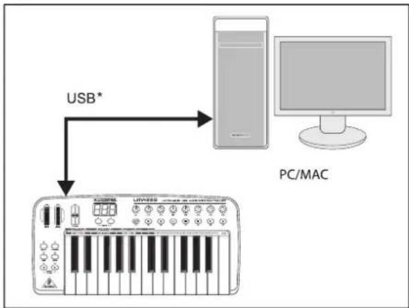
flowchart
graph TD
    A["PC/MAC"] -->|USB*| B["Wireless Audio System"]
* included
Fig. 1.1: Power supply via USB
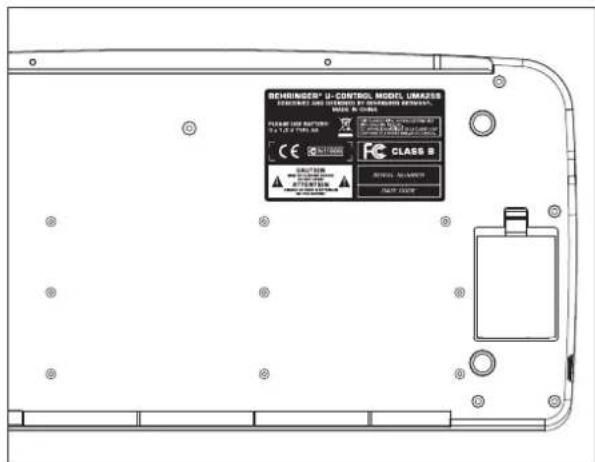
Fig. 1.2: Battery compartment on the bottom side of the UMA25S
Open the battery compartment by pressing the release tab carefully in the direction of the battery compartment while pulling the lid of the compartment upward.
Please note the following points when inserting the batteries:
The + symbol of the batteries must coincide with the + symbol of the compartment! Incorrect polarity will damage the electronics!
Do not use old and new batteries together! When replacing batteries, always change all 3 batteries at the same time.
▲ Do not use damaged batteries. The UMA25S might also be damaged because of chemical leakage.
If you do not use the UMA25S for an extended period of time, please remove the batteries from the compartment. The batteries could leak and damage the device.
After inserting the batteries, please close the battery compartment and make sure the release tab snaps into place.
External power supply:
If you neither want to draw the power supply via USB nor power the device with batteries, there is yet another possibility to connect the UMA25S to an external power supply unit. Please observe the correct operational data (DC 9 V; 200 mA) and correct polarity of the connector. Further information can be found above the DC input on the rear panel of the device. Reverse polarity may cause damage to the electronics.
IMPORTANT INSTALLATION INFORMATION:

The sound quality may diminish within the range of powerful broadcasting stations and high-frequency sources. Increase the distance between the transmitter and the device and use shielded cables for all connections.
1.1.3 Online registration
Please register your new BEHRINGER equipment right after your purchase by visiting http://www.behringer.com and read the terms and conditions of our warranty carefully.
Should your BEHRINGER product malfunction, it is our intention to have it repaired as quickly as possible. To arrange for warranty service, please contact the BEHRINGER retailer from whom the equipment was purchased. Should your BEHRINGER dealer not be located in your vicinity, you may directly contact one of our subsidiaries. Corresponding contact information is included in the original equipment packaging (Global Contact Information/European Contact Information). Should your country not be listed, please contact the distributor nearest you. A list of distributors can be found in the support area of our website (http://www.behringer.com).
Registering your purchase and equipment with us helps us process your repair claims more quickly and efficiently.
Thank you for your cooperation!
1.1.4 Product contents
▲ 1 UMA25S keyboard with 2 strap buttons
▲ 1 shoulder strap
▲ 1 BEHRINGER HS1000 stereo headset with separate 1/8" connectors for headphone and microphone
▲ 1 printed manual
▲ 1 printed quick-start guide "Podcasting with the UMA25S"
▲ 2 CDs: CD 1 contains energyXT2 Compact for Mac computers and PCs
CD 2: BEHRINGER ULTIMATE SOFTWARE PACKAGE
▲ 1 USB cable
▲ 1 soft gig bag with shoulder strap
1.2 System requirements
A current Windows PC or Mac computer with one USB port is required for USB operation. Both USB 1.1 and USB 2.0 are supported.

The UMA25S supports the USB MIDI compatibility of Windows XP/Vista und Mac OS X operating systems.

The UMA25S can also be operated as a stand-alone MIDI controller with no PC connected. Software control via MIDI is also possible, provided your computer has a MIDI interface.
1.3 Hardware configuration
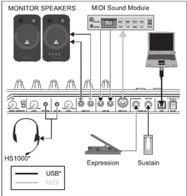
To connect the UMA25S to your computer, use the provided USB cable. Connect the supplied headset as shown in Fig. 1.3. Optionally, hook up further units to the UMA25S as can be seen from the diagram.

Some headsets may cause interferences (humming). Should this be the case, make sure the UMA25S is sufficiently grounded, for example, by connecting a grounded mixer to the LINE OUT connectors. If necessary, reduce the microphones's input volume level with the LEVEL control .19
flowchart
graph TD
    A["MONITOR SPEAKERS"] --> B["MIDI Sound Module"]
    B --> C["USB*"]
    B --> D["MIDI"]
    C --> E["HD/LED"]
    D --> F["HD/LED"]
    E --> G["HD/LED"]
    F --> H["HD/LED"]
    G --> I["HD/LED"]
    H --> J["HD/LED"]
    I --> K["HD/LED"]
    J --> L["HD/LED"]
    K --> M["HD/LED"]
    L --> N["HD/LED"]
    M --> O["HD/LED"]
    N --> P["HD/LED"]
    O --> Q["HD/LED"]
    P --> R["HD/LED"]
    Q --> S["HD/LED"]
    R --> T["HD/LED"]
    S --> U["HD/LED"]
    T --> V["HD/LED"]
    U --> W["HD/LED"]
    V --> X["HD/LED"]
    W --> Y["HD/LED"]
    X --> Z["HD/LED"]
    Y --> AA["HD/LED"]
    Z --> AB["HD/LED"]
* included
Fig. 1.3: Hookup example
Operating modes
There are different ways of using the UMA25S as a controller: a) Connect the MIDI output of the UMA25S to external MIDI equipment (rack synthesizers, samplers and similar); b) Connect the UMA25S to your computer via USB to control your music software.
The first option does not include the functionality of the UMA25S' audio interface. The MIDI routing changes depending on the operating mode you are working in.

1.3.1 Stand-alone mode
In case the USB connection is not available or detected, the UMA25S automatically switches to the stand-alone mode. In this mode, you can use the UMA25S to control external units via the MIDI output.

flowchart
graph TD
    A["Sampler"] -->|MIDI IN| B["MIDI Sound Module"]
    B -->|MIDI IN| C["MIDI OUT"]
    C -->|MIDI OUT| D["Output"]
    style A fill:#f9f,stroke:#333
    style B fill:#ccf,stroke:#333
    style C fill:#cfc,stroke:#333
    style D fill:#fcc,stroke:#333

flowchart
graph TD
    A["UMA DATA SEND"] --> B["DATA SEND"]
    B --> C["MIDI OUT"]
    D["USB"] --> E["STAND ALONE MODE"]
Fig. 1.4: Stand-alone mode
1.3.2 USB mode (default)
This is the default setting when the device is turned on. If the UMA25S is connected to a computer via USB, the keyboard automatically switches to this mode. In the USB mode, you can choose between 2 options: MIDI THRU or MIDI OUT.
1. USB mode with MIDI THRU (default):

flowchart
graph TD
    A["Software Synthesizer"] -->|move/fade| B["MIDI Sound Module"]
    C["Software Mixer"] -->|move/fade| B
    D["Software Sequencer"] -->|push| E["Laptop"]
    B --> F["MIDI OUT"]
    E --> F
    F --> G["USB"]
    F --> H["MIDI"]

flowchart
graph TD
    A["MIDI OUT"] --> B["DATA SEND"]
    B --> C["UMA DATA SEND"]
    C --> D["USB"]
    D --> E["DUMP RECEIVE"]
    E --> C
    style C fill:#f9f,stroke:#333
    style B fill:#ccf,stroke:#333
    style D fill:#cfc,stroke:#333
Fig. 1.5: USB mode with MIDI THRU
In this mode, the keyboard messages are sent to the computer via USB. The messages from the computer are transmitted to the UMA25S (data reception) and simultaneously to all MIDI units which are connected to MIDI OUT. This mode is ideal for playing the keyboard and controlling further MIDI hardware (samplers, rack synthesizers, etc.) with the sequencer.
- USB mode with MIDI OUT:


flowchart
graph TD
    A["Software Synthesizer"] -->|move/fade| B["software mixer"]
    C["Software Sequencer"] -->|push| D["software mixer"]
    E["MIDI Sound Module"] -->|USB| F["MIDI OUT"]
    G["USB"] --> F
    H["MIDI"] --> F
    I["USB"] --> F
    J["MIDI"] --> F
    K["USB"] --> F
    L["MIDI"] --> F
    M["USB"] --> F
    N["MIDI"] --> F
    O["USB"] --> F
    P["MIDI"] --> F
    Q["USB"] --> F
    R["MIDI"] --> F
    S["USB"] --> F
    T["MIDI"] --> F
    U["USB"] --> F
    V["MIDI"] --> F
    W["USB"] --> F
    X["MIDI"] --> F
    Y["USB"] --> F
    Z["MIDI"] --> F

flowchart
graph TD
    A["UMA DATA SEND"] -->|DATA SEND| B["MIDI OUT"]
    A -->|DUMP RECEIVE| C["USB"]
    C --> D["USB INTERFACE MODE (MIDI OUT)"]
Fig. 1.6: USB mode with MIDI OUT
In this mode, the keyboard messages are transmitted via USB to the computer and simultaneously to MIDI OUT. The messages from the computer are only picked up by the UMA25S and not passed on to MIDI OUT.
This mode is ideal for recording your keyboard performance to your computer even when your sequencer or virtual instrument produces high latencies. To avoid this problem, use a rack synthesizer while recording but the virtual instrument during playback. The MIDI messages are sent to the computer and, at the same time, to the MIDI output.
Selecting the USB mode:
- Press the EDIT/EXIT push button.
- Press the key on the keyboard labeled MIDI OUT or MIDI THRU.
- Press ENTER to confirm or EDIT/EXIT to cancel.
The selected USB mode is now active and the keyboard automatically switches back to Play Mode.
2. Software installation
2.1 Driver installation
With Windows XP/Vista and Mac OS X operating systems, the UMA25S is detected as soon as you connect a USB cable to your computer. After detection, you can kick off right away. Thanks to the implementation of Core Audio in Mac OS X, it is possible to process your audio with extremely low latency.
2.1.1 Windows XP MIDI driver
Optionally, you can install the BEHRINGER MIDI driver found on the supplied CD. The advantage of this driver is its multi-client support, which lets you simultaneously use several MIDI programs together with the UMA25S. Another advantage is that the model name is displayed in the selection dialog box of the MIDI driver.
Information on installing the driver is found on the CD in the ReadMe file of the according folder.
Find more software and driver updates at www.behringer.com.
2.1.2 Windows XP/Vista audio driver
Optionally, you can also install the BEHRINGER USB ASIO driver, which is included on the CD as well. Use this driver in case you want to work with the least possible latency of audio signals. Most professional music applications, such as Ableton Live and energyXT2 Compact, use ASIO drivers.
Information on installing the driver is found on the CD in the ReadMe file of the according folder.
2.2 Music software
The UMA25S comes with a comprehensive software bundle that covers virtually all aspects of music production and live performance plus lets you produce your own audio podcasts.
energyXT2 Compact (on separate CD) gives you a fully professional Digital Audio Workstation (DAW) for Mac OS X and Windows XP/Vista operating systems, ideal for sophisticated and creative audio and MIDI productions as well as live performances. The included application Audacity is simply the universal audio editor for Mac and PC. What's more, you can find so-called hosts, or "hosting" applications, on the CD which allow you to load plug-ins (instruments and effects) and use these for live performances.
2.2.2 Instruments and effects
Many instruments and effects (more than 150 arranged in categories) are found in the „Win“ and „Mac“ folders that can be used in the applications described in 2.2.1. The scope ranges from virtual analog synthesizers, electric organ emulations, pianos, drum machines to high-quality studio effects such as reverb, chorus, compressor, delay and many more. But we’ve also added several exotic ingredients to spice up your sound. For example, there’s the lo-fi effect, the Tube Amp Simulator, the Chinese Flute and the Singing Monk.
2.2.3 Podcasting software
As a special bonus, we've thrown in the proven and popular podcasting software bundle, giving you the tools you need to make your own podcasts—from the first spark of an idea to uploading your final podcast. As for the supplied headset, you can use it to capture spontaneous ideas or comment on your own music. For details, refer to the included podcast quick-start guide.
- Controls and connections
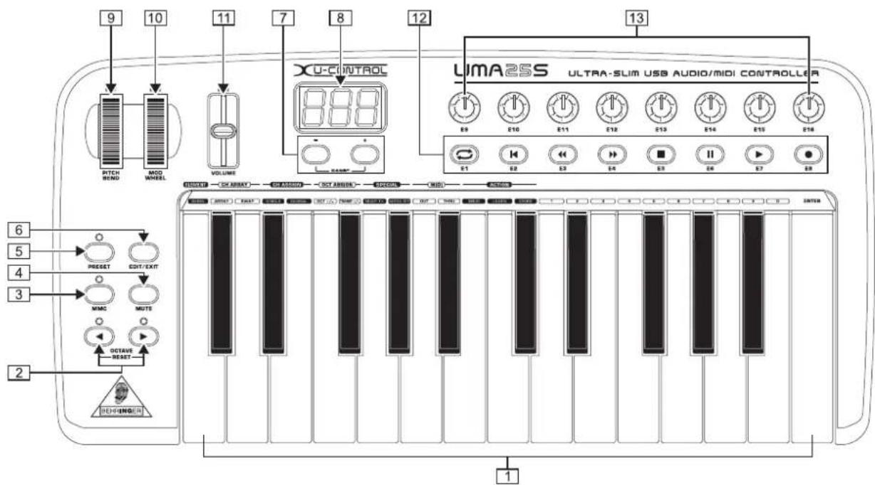
Fig. 3.1: Top view of the UMA25S
The keyboard of the UMA25S has 25 velocity-sensitive, full-size keys with half action.
2 The OCT </> push buttons allow you to shift the keyboard range up to 4 octaves up or down. These push buttons are also used for transposition (see Chapter 5.2.2).
3 Press the MMC push button to use the default MMC (MIDI Machine Control) functions of the control elements E1 to E8. The MMC functions are printed on these control elements.
4 Press the MUTE push button to suppress sending MIDI messages. This allows you to move control elements without changing the parameter values.
5 Press the PRESET push button to load a preset.
6 Press the EDIT/EXIT push button once to switch to Edit Mode. By pressing the button a second time, you exit Edit Mode without having accepted any changes.
7 The - / + push buttons let you select a preset. Press both buttons at the same time to silence stuck MIDI notes (PANIC).
8 The 3-digit LED display briefly indicates the current firmware version when the keyboard is switched on, after which the selected preset number is displayed. In Play Mode, the display shows the value changes in real time when operating the control elements. In Edit Mode, the display shows the MIDI commands, program and channel numbers as well as parameter values.
9 The PITCH BEND wheel (E17) lets you change the pitch in real time. This way a tone can be bent several semitones up or down while playing. The desired pitch interval is adjusted on the controlled device. The PITCH BEND wheel returns to the center position as soon as you let go of it.
10 The MOD WHEEL (E18) works like a typical modulation wheel (MIDI CC 1). When you let go of the modulation wheel, it keeps the set value.
11 The VOLUME slider (E19) controls the volume (MIDI Controller 07).
The PITCH BEND wheel, the modulation wheel and the VOLUME slider are not restricted to their preconfigured functions, but can also have other control functions assigned to them.
12 The push buttons E1 - E8 can have any MIDI functions assigned to them. By pressing the MMC push button 3 once, these push buttons use the preconfigured transport control functions (see Chapter 5.5.7).
13 The 8 high-resolution rotary knobs E9 - E16 generate Continuous Controller messages. In Edit Mode, the rotary knobs can be assigned to any controller number.
14 If the Direct Monitor function is turned on (press switch 15), the MIX control allows you to adjust the volume level balance between the recording signal and the playback signal.
15 The MONITOR ON/OFF switch activates the Direct Monitor function. The recording signal found at the MIC or LINE input is fed to the output connectors LINE OUT and PHONES in order to avoid latency and the resulting timing problems while recording.
16 The LEVEL control lets you adjust the volume level of the headphone signal. Turn the control completely to the left before plugging in the headphones to avoid damage due to high volume levels.
17 Plug the green headphone connector of the supplied headset into the PHONES connector.
18 Plug the red connector of the headset or any dynamic microphone into the MIC IN connector.

Fig. 3.2: Audio connectors on the rear panel
19 The LEVEL control adjusts the input volume of the microphone signal. Make sure the input signal does not clip (distortion).
To prevent unwanted noise, always be sure that the input volume level is turned down to MIN when a microphone is not being used.
20 The LINE OUT connector lets you connect RCA audio cables.
21 The LINE IN connector lets you connect RCA audio cables.

Fig. 3.3: Rear panel connectors
22 MIDI OUT allows the UMA25S to connect to a computer. On the other hand, it provides a connection to additional MIDI devices, making the UMA25S a full-fledged MIDI interface for the host computer next to its master keyboard functionality.
[23] The EXPRESSION connector lets you hook up a foot pedal which can be used to control assignable MIDI data. The foot pedal typically controls the volume level, which is then referred to as expression pedal, but can also be used to control a filter's cutoff frequency or even a typical wah effect.
24 The SUSTAIN connector allows you to connect a Sustain pedal. This connector is assigned by default to the MIDI parameter "Damper Pedal" (Sustain, CC 64), which represents a switch controller. When the pedal is pressed (and held) while in normal Play Mode, it generates a controller with the value 127. As soon as the pedal is released, the controller jumps to the value 0 (which is the typical behavior of a piano's sustain pedal). Aside from this, you can assign the pedal connector to any MIDI controller as is the case with the push buttons.
25 This is the USB connector on the UMA25S. The connector (type B) on the device is connected to a free port (type A) on the host computer using the supplied cable. It is compatible with both USB 1.1 and USB 2.0 standards.
26 Use the DC IN connector to supply the UMA25S with power from an external power adapter (not included).
27 The POWER switch is used to turn the UMA25S on and off. Be sure the POWER switch is turned to the "Off" position when connecting to the mains.
Please close all software applications before turning off the UMA25S or disconnecting the USB cable while the computer is on.
- UMA25S as audio interface

flowchart
graph TD
    A["C-3"] --> B["MONITOR SPEAKERS"]
    C["HS1000*"] --> B
    B --> D["UMA25S"]
    D --> E["Output"]
    style A fill:#f9f,stroke:#333
    style C fill:#f9f,stroke:#333
    style B fill:#ccf,stroke:#333
    style D fill:#cff,stroke:#333
* included
Fig. 4.1: Using the audio connectors
The UMA25S provides a professional recording interface between mixer and computer when used alongside a suitable mixer. This type of setup allows you to record several signals onto the computer and to play several recorded takes or playbacks simultaneously. Additionally, it lets you listen to the entire recording on loudspeakers (or headphones). Figure 4.1 shows a possible setup with the UMA25S.
Connect the subgroup outputs with the inputs of the UMA25S. It is possible to connect either the TAPE INPUT connectors or your monitor speakers to the outputs of the interface. For monitoring purposes, plug the stereo headphones into the PHONES output on the UMA25S or into the headphone output on the mixer. Use the supplied USB cable to connect your computer by way of the USB port.
By routing the channels you want to record to the subgroups, it is now possible to use the mixer's channels to record one instrument after the other onto your computer. If you connect the outputs of the UMA25S to the free channel inputs (not via TAPE INPUT), make sure that the signal is not switched to the subgroup but to the main output of your mixer to avoid feedback. Be also sure to select the correct monitoring paths in the Control Room section on the mixing console.
If you feed the UMA25S back through a channel input (not TAPE INPUT), you can set up an additional monitor mix for performing musicians by using the Aux Send (for example, Aux 1) of the specific channel. In case the musicians want to hear themselves as well as the playback or previous recording takes, use the Aux Sends in the recording channels to mix the recording signals with the monitor mix.

5. UMA25S as USB/MIDI controller
At the highest control level of the U-CONTROL, you play and control the MIDI data (Play Mode). The UMA25S has an array of control elements with which you can control your MIDI equipment via the MIDI output 28t with which you are able to control your computer applications via USB (using the MIDI standard). Most Digital Audio Workstations (DAWs) are capable of receiving control data according to MIDI specifications.
The controls comprise keyboard, Pitch Bend and Modulation wheel, Volume control slider, 8 rotary knobs, 8 push buttons as well as Sustain and Expression pedals.
Display:
The current firmware version appears on the screen as soon as the keyboard is switched on, after which the current preset number is shown. When moving a control element, the value changes are displayed.
Control elements:
It is possible to use more than one button, knob, slider, etc., at the same time and that their data are simultaneously sent via MIDI.
In principle, there are two options for assigning control elements:
▲ You are using one of the presets with the default controller configuration (see Table 7.3). In this case, you need to specify the assignments on the receiving device.
▲ You are you using your own controller configuration that you created in Edit Mode. Find out how to make assignments on the UMA25S in Chapter 5.4.
The following gives you a detailed description on how to use the UMA25S. Please note the difference that is made between push buttons (see control elements 2 - 7 and 12) and keys on the keyboard (control element A) Please do not confuse these two control elements!
5.1 Presets
The UMA25S has 16 memory locations to store your own presets. You can find the settings of the default presets (Table 7.4) in the appendix. The most recently used preset is loaded when the device is switched on.
5.1.1 Loading presets
There are several ways to load a preset:
Selecting presets directly:
▲ Press the PRESET push button for a second and select the preset you want to use with the push buttons E1 – E8. The new preset number is shown on the display.
or:
▲ Press and hold down the PRESET push button while pressing the key (1 - 8) with the number of the preset you want to use. The new preset number is shown on the display.
Selecting presets by manually stepping up or down:
▲ Select a preset with the +/- push buttons (7) and below the display. The new preset number is shown on the display. Make sure that none of the push buttons 3 to 6 (MMC, MUTE, PRESET, EDIT) are pressed.
or:
▲ Press and hold down the PRESET push button while turning one of the rotary knobs E9 – E16. The preset number is shown on the display. As soon as you press the PRESET push button a second time (LED goes out), the new preset is activated.
5.1.2 Storing presets
- Press the EDIT/EXIT push button for \$6 second.
- Press the key with the STORE function. "Str" appears on the display, representing the Store function.
- Press one of the 8 push buttons E1 – E8 or turn one of the rotary knobs E9 – E16 to select the memory location in which you want to store your preset.
- Press the ENTER key to confirm.
You can also select the memory locations 1 to 8 using your keyboard (keys labeled with the numbers 1 - 8). The memory locations 9 to 16 can only be selected using the rotary knobs.
The EDIT LED goes out.
▲ If you want to overwrite the current preset, press the STORE key and then the ENTER key (skip step 3).
▲ You can cancel the storing process by pressing the EXIT push button.
We intentionally did not include an auto-store function. This way you can assign a different MIDI message to a control element without changing the current preset. If you want to restore a preset, simply load another preset and then return to the old preset. All data have now been restored, including the default function of the control element that had been changed for the time being.
5.1.3 Restoring default presets
- Press the EDIT/EXIT and MUTE push buttons together. The display shows "GLb" (for Global Mode).
- Turn the E14 rotary knob. The display shows "FAC" (for Factory Reset).
- Press the ENTER key to confirm.
Caution! With Factory Reset, all configured data and user presets are irreversibly deleted! To avoid an accidental deletion, save your presets by sending a SysEx dump to your computer beforehand (see Chapter 5.7).
▲ You can cancel the process by pressing the EXIT push button.
5.2 Real-time control using the control elements
The UMA25S' possibilities of application are extremely versatile. The following gives a couple of general instructions and examples to help you get started as quick as possible.
What exactly does the UMA25S do?
Simply put, it's a remote control for all kinds of MIDI equipment. An entire array of control messages can be generated by the keyboard, slider, rotary knobs and push buttons as well as the foot pedals. These control elements allow you to control various functions of external devices (hardware and software) in real time. That's particularly the case with software mixers, sound generators and effects. The software applications are often copies of "real" gear—their functionality simulated and displayed on the computer.
What can I control with the UMA25S?
Basically, you can control any device that is MIDI compatible. Both hardware and software MIDI devices are controlled in exactly the same way. The only difference between them is the wiring.
Below are a couple of suggestions on how you can use your UMA25S:
▲ Playing external sound generators (for example, MIDI sound modules, rack synthesizers and virtual instruments)
▲ Editing sound parameters of (virtual) synthesizers, sound samplers and GM/GS/XG sound generators
▲ Controlling parameters on effects equipment and software plug-ins, such as effects processors, compressors and digital equalizers
▲ Remotely controlling software mixers (functions for volume, panorama, mute, etc.)
▲ Remotely controlling transport functions (Play, Fast Forward, Stop, etc.) on sequencers, hard-disk recorders, drum machines, etc.
▲ Live control of volume and sound parameters of sound modules on stage
▲ Remotely controlling groove boxes, step sequencers, MIDI generators and other “live” software
▲ Controlling program changes and volume level on sound generators
▲ Suitable for band keyboardists, DJs, sound engineers, home and project studio owners, theater technicians, etc.
And how does it work?
Each control element of the UMA25S can be assigned to particular MIDI parameters. Assignments are carried out in Edit Mode (see Chapters 5.3 and 5.4). Whenever one of these control elements is used, the UMA25S generates the control data assigned to this control element which are then transferred to external devices over a data link. For this reason, the VOLUME slider is set by default to send data that controls the volume level of a channel, for example.
The control data generated by the individual control elements are also referred to as MIDI messages. Generally, MIDI messages can be divided into three major groups:
Channel Messages: These messages are used to transmit channel-specific control information. An example of a channel message is the Note On message. As soon as a key is played on the UMA25S' keyboard, the device generates a message which holds the information for pitch, channel number and velocity. This way the receiving sound generator recognizes which tone has to be played.
▲ System Messages: These messages are not channel-specific, but affect the entire system to which they are sent. They are divided into three subcategories: System Exclusive Messages (for operating system backup, updates and management of memory contents); System Real-Time Messages (for remote control of other devices, etc.); System Common Messages (for synchronizing several devices, etc.).
▲ Control Messages: These are also known as Control Changes or Controllers, abbreviated to "CC". There are 128 controllers in total, numbered from 0 to 127 (refer to the table of controllers in the appendix). The controllers are channel-specific.
MIDI information consists of control data and contains no audible audio data! The data transmission takes place over 16 channels.
5.2.1 Changing the velocity curve
You can adjust the UMA25S' sensitivity which has an effect on the velocity with which the keys are pressed and therefore also on the volume level.
- Press the EDIT/EXIT push button.
-
Turn the E9 rotary knob completely to the right. "crV" (which stands for Velocity Curve) appears on the display.
-
Select the desired velocity curve with the E11 rotary knob. You can select one of the following options:
FIXED: The velocity curve is switched off (as is the case with an organ). The keyboard always sends the same velocity value. This value can be adjusted with the E12 rotary knob.
SOFT: The keyboard responds to the finest nuances. Applying different pressures to the keys can make a big difference in volume.
MEDIUM: The velocity curve is linear.
HARD: The velocity curve is non-sensitive. You have to hit the keys very hard in order to play loud.
4a. Press the ENTER key to confirm.
4b. Alternatively, press the EXIT push button to cancel any changes made.
These settings need not be saved.
5.2.2 The Octave and Transpose functions
The OCT </> push buttons can be used to shift the pitch in octave intervals. This is useful because the UMA25S consists only of 25 keys, whereas the MIDI specification includes 128 notes. In case you want to play a bass line, it can be useful to move the keyboard range downward.
Alternatively, the OCT </> push buttons can be used to tranpose notes in semitones so that you can play a piece in a key that works for you. In order to do so, you need to adjust the settings in Edit Mode.
When the power is turned on, the Octave function is active by default.
Octave function:
Use the OCTAVE </> push buttons to shift the keyboard's playing range up to 4 octaves.
▲ Press OCT> to play the keyboard an octave higher. The OCT> LED lights up.
▲ Press OCT< to play the keyboard an octave lower. The OCT< LED lights up.
▲ Press OCT< and OCT> at the same time to return to the default octave range.
The status of the Octave function is indicated by the glowing (1 octave) and flashing (2 and more octaves) of the respective push button's LED.
When the power is turned on, the default octave range is restored.
Activating the Octave function (OCT ASSIGN):
When the Transpose function is active, you activate the Octave function as follows:
▲ Press the EDIT/EXIT push button. The device switches to Edit Mode. The EDIT LED lights up.
▲ Press the OCT +/- key to select the Octave function.
▲ Press the ENTER key to confirm. The device switches back to Play Mode (EDIT LED goes out).
Transpose function:
Use the OCTAVE </> push buttons to transpose upward or downward in semitone steps.
▲ Press the OCT > to transpose upward in semitone steps.
▲ Press OCT < to transpose downward in semitone steps.
▲ Press OCT < and OCT > simultaneously to return to the default key.
The status of the Transpose function is indicated by the glowing (1 semitone) and flashing (2 and more semitones) of the respective push button's LED.
When the power is turned on, the default key is restored.
Selecting the Transpose function:
When the Octave function is active, you activate the Transpose function as follows:
▲ Press the EDIT/EXIT push button. The device switches to Edit Mode. The EDIT LED lights up.
▲ Press the TRANSP +/- key to select the Transpose function.
▲ Press the ENTER key to confirm. The device switches back to Play Mode (EDIT LED goes out).
Octave settings, which have possibly been made, are maintained when switching over to the Transpose function.
5.2.3 The MMC function
The control elements E1 to E8 have been preconfigured to control MIDI Machine Control (MMC) messages, and they are activated by pressing the MMC push button .3
▲ Press the MMC push button to activate the MMC function. The push button LED lights up.
The MMC functions that are assigned to the control elements by default are as follows:
E1 Loop: Activates the playback loop feature of the controlled music software application.
E2 Locate: Jumps to the beginning of the track.
E3 REW: Rewinds.
E4 FFW: Fast-forwards.
E5 Stop: Stops playback. By pressing Play (E7) again, the track is played from the beginning.
E6 Pause: Pauses playback. By pressing Play (E7) again, the track is played from the current position.
E7 Play: Plays back.
E8 Punch In: Records.
In case your sequencer does not support receiving MMC messages, you can probably control the transport section using note numbers or CC messages. The MMC messages can be assigned to the 8 push buttons E1 – E8 in such a way that the assigned functions are maintained independent of preset specification. These functions are also preserved after the device is switched off and can be activated at all times by simply pressing the MMC push button. This means that the push buttons E1 – E8 can each share two functions: first, the function assigned within a preset, and second, the assigned function that coincides with presets as soon as the MMC push button is activated.
Assigning the 8 push buttons is described in Chapter 5.4. You simply have to press the MMC push button (LED lights up) before activating Edit Mode.
5.2.4 The Panic function
The Panic function is provided to silence stuck MIDI notes. A MIDI note can get stuck when the connection between the sending and the receiving device is interrupted for some reason or other and the required Note Off message cannot be received. This is perceived as a stuck note that doesn't fade out.
So, if you execute the Panic command, an "All Notes Off", an "All Sound Off" and a "Sustain Pedal Off" message is sent over all 16 channels. This way all connected sound generators are silenced on the spot, after which you can continue your work as usual.
▲ Press both push buttons (+) at the same time to trigger a Panic command. "Pnc" appears on the display for a short time.
5.2.5 The Mute function
▲ Press the MUTE push button . Its LED lights up.
The Mute function lets you suppress sending MID messages. This way you can change the positions of control elements without affecting the current settings of the receiving device. However, value changes are shown on the display provided it is active for the control element being moved.
▲ Press the MUTE push button again. Its LED goes out.
The Mute function does not affect the push buttons E1 – E8 and the Sustain pedal.
5.3 Assignment of control elements using the Learn function
The easiest way to assign MIDI functions to individual control elements is to use the Learn function over remote assignment. For example, MIDI data sent from a MIDI sequencer to your U-CONTROL are assigned to a control element in advance.
Not only CC, NRPN and Note messages can be received with the Learn function, but almost any type of MIDI data including short SysEx strings.
- Press and hold down the EDIT/EXIT push button.
- Operate the control element that is supposed to learn the MIDI function.
- Release the EDIT/EXIT push button.
- Press the LEARN key. "Lrn" appears on the display while the MIDI device waits for an external MIDI message.
- Transmit the MIDI message to the UMA25S from the device you want to control.
- If valid MIDI data are received, the display shows "Gd!" (good). If invalid, incorrect or too long, "Err" (error) appears on the display.
7a. Press the ENTER key to confirm.
7b. Alternatively, press the EDIT/EXIT push button to cancel the changes made.
The device switches to Play Mode (EDIT LED goes out).
All settings made with this function are stored temporarily! If you want to store the settings permanently, save them in a preset (see Chapter 5.1.2).
Example of the Learn function:
In order to control the main volume level of a virtual instrument with the E19 slider, follow the steps below:
- Press and hold the EDIT/EXIT push button.
- Move the E19 slider.
- Release the EDIT/EXIT push button.
- Press the LEARN key.
- Now move the volume control of the software instrument with your computer's mouse.
- When "Gd!" appears on the display, press the ENTER key.
- To save these settings, store them in a preset.
5.4 Assignment of control messages in Edit Mode
It is possible to specify settings that are different from the presets. To do so, you need to determine which control elements on the UMA25S generate which MIDI messages.
You need to specify how the incoming controllers are to be interpreted on the slave unit. At this point, we suggest you refer to the user manual of the slave unit.
General assignment of control messages in Edit Mode:
- Press and hold down the EDIT/EXIT push button. The device switches to Edit Mode and "Edt" appears on the display.
- Use the control element you want to edit. The name of the control shows up on the display (for example, "E10").
- Release the EDIT/EXIT push button. Its LED lights up.
- Use the rotary knobs E9 – E16 to assign the MIDI messages to the selected control element. The applicable MIDI messages and their descriptions are found in the tables of Chapter 5.5.
In case you want to check the current parameter settings, press the push button (E1 - E8) found under the rotary knob whose function you want to examine. As soon as the push button is pressed, the settings appear on the display for a short time. Alternatively, use the Show Element function (see Chapter 5.6.1).
5a. Press the ENTER key to confirm. The EDIT LED goes out.
5b. Alternatively, press the EDIT/EXIT push button to cancel the changes and exit Edit Mode. The EDIT LED goes out.
All settings made with this function are stored temporarily! If you want to store the settings permanently, save them in a preset (see Chapter 5.1.2).
The various MIDI functions are described in detail in Chapter 5.5.
Comments on Step 4:
In Edit Mode, all settings are made by turning the knobs E9 – E16. The available setting options depend on the data types being used.
| E9 E10 E11 E12 E13 E14 E15 E16 | |||||||
| MIDI Data Type | MIDI Send Channel | Parameter | Value 1 | Value 2 | Controller Mode | Controller Option | Display Value |
Table 5.1: General assingment of rotary knobs in Edit Mode
MIDI Data Type:
The E9 rotary knob lets you select the message type that is to be assigned to a control element. Refer to Chapter 5.5 for information on MIDI messages.
MIDI Send Channel:
The E10 rotary knob allows you to select the MIDI channel on which the message is supposed to be sent. When Channel 0 is selected, the message is sent on the GLOBAL SEND CHANNEL (see Chapter 5.7).
Parameter, Value 1, Value 2:
The rotary knobs E11 to E13 allow you to adjust the parameters and the corresponding values of the selected MIDI message. The parameters vary according to the MIDI message (see Chapter 5.5).
Controller Mode:
The E14 rotary knob is provided to determine the switch behavior of the selected control element. This option is only available for switch elements (push buttons).
The control push buttons support the controller modes "Toggle On", "Toggle Off" and "Increment". Toggle On is comparable to a switching function (for example, the light switch of a room). The "On" value, which is specified with the E12 rotary knob (value 1), is sent by pressing the push button the first time. Press the push button a second time to send the "Off" value, which is specified with the E13 rotary knob (value 2). This setting is ideal for triggering drumloops from a sampler (press once = Start, press a second time = Stop).
Toggle Off corresponds to a push button function, which is comparable to the switch of an electric door opener. The On value (value 1) is sent by pressing the push button. The Off value (value 2) is sent by releasing the push button. You should use this mode when triggering short sound effects and samples (similar to playing a keyboard).
The Increment option is only available for the messages Program Change, CC, NRPN and After Touch. This mode allows a stepwise increment of the controller value each time the push button is pressed. Use E15 to adjust the step interval.
Controller Option:
Select the controller mode "Increment" to determine the step interval of the push buttons by using the E15 rotary knob. This means that each time you press one of the push buttons, the transmitted value is increased by the step interval you specified in advance. If the step interval is set to "10," values 0, 10, 20, 30 ... 110, 120, 0, 10, etc. are sent one after another. You can also enter negative values (for example, -10) to achieve a gradual decrement. In case you have specified the lowest and highest transmittable values using the E12 and E13 rotary knobs, all other values stay within this range. With this function, you can use your U-CONTROL to operate control push buttons that have more than two switching states.
Display Value:
Use the E16 rotary knob to determine whether value changes are to be displayed on screen or not. If you decide to use the display for this purpose, you can see the current values while using the control element. The preset number reappears shortly after letting go of the control element.
5.5 MIDI Messages
5.5.1 Program Change and MIDI Bank Select
Program Change messages are used to activate the memory banks of the connected devices. 128 program numbers are available to activate presets. For devices with more than 128 presets, there is the Bank Select function which allows you to select a memory bank before sending a Program Change.
The Bank Select message consists of two parts: an MSB (Most Significant Bit) part and an LSB (Least Significant Bit) part. The MSB part defines a range of 128 values and is the more important part of the Bank Select message for many MIDI devices. The LSB part defines each one of the 128 MSBs in 128 additional steps. The numbering for both parts ranges from 0 to 127.
In total, the Bank Select message offers an enormous range of 128 × 128 = 16,384 different values available for bank numbers. In theory, this means that you could use external devices with as many different banks. Considering the fact that each single bank includes another 128 single programs, you get unbelievable 2,097,152 different possibilities to organize your programs.
Use the E11 and E12 rotary knobs to select the banks. If a MIDI device contains more than 128 presets/programs, a Bank Select message has to be sent beforehand. Even though this is a controller command, it has to be sent before the Program Change (and is therefore adjustable) since it is linked to the preset change. If the Bank Select message is not needed, simply select "Off".
If you choose a control which is a rotary knob, you can use the knob to select a program number directly. It is also possible to assign a permanent program number (selectable with E13), which is sent when using the control. For push buttons/switch elements, you can use the push button to select a permanently assigned program number (using E13). This is practical when using the same preset over and over again. Adjust the switch behavior by using E14: "Increment" means that every time you press the push button the next incremental preset number—in a predefined interval—is activated. "Single Preset" means that the push button always switches to the same preset number.

Table A.1 on the supplementary sheet gives you an overview of the rotary knob assignment in Edit Mode.
Examples of Program Changes:
Example 1:
You want the push buttons E1 – E8 to switch the program numbers 71 – 78 of your external rack synth. Program the first push button as follows:
- Press and hold down the EDIT/EXIT push button while pressing the E1 push button. When E01 appears on the display, release the EDIT/EXIT push button.
- Turn E9 completely to the left so that the display shows "PC" (which stands for Program Change).
- Use E10 to select the MIDI channel on which your synth is ready to receive.
-
Turn E11 and E12 completely to the right so that "OFF" appears on the display.
-
Select the program number 71 by using E13.
-
Select "Single Preset" by using E14.
-
If the program number is to show on the display when pressing the push button, select "ON" with E16.
-
Press the ENTER key to confirm. The EDIT LED goes out.
Result: Each time you press the push button, the program number 71 is activated on the slave unit.
Program the push buttons E2 - E8 the same way with ascending program numbers up to 78.
Example 2:
In case you want to program a push button in order for it to activate a new preset every time it is pressed, this can be accomplished in the following way: E11 = Off, E12 = 0; E13 = 127; E14 = Increment; E15 = +8.
Result: The program number 0 is transmitted the first time the push button is pressed, 8 the second time, 16 the third time, then 24, etc. This way you can select each first preset of a sound bank, which is organized in groups of eight.
Example 3:
In case you want to activate preset no. 6 in bank 8, adjust as follows: E11 = 8, E12 = Off, E13 = 6.
Result: First, the UMA25S transmits the higher ranking bank number 8 as CC, followed by the program number 6.
5.5.2 Control Changes
The Control Change messages (CC) belong to the most "powerful" MIDI messages. They allow you to control plenty of parameters and functions. You can assign CC messages to each control element on the UMA25S. Since it is possible to use push buttons, sliders and rotary knobs, the controller values can be controlled either statically or dynamically in real time. A list of the assigned standard controller numbers are found in Table A.1 of the supplementary sheet.
The Controller message consists of a controller number and the included controller values. The E11 rotary knob is used to determine the controller number.
Continuous elements allow you to define the value range with the E12 (minimum value) and E13 (maximum value) rotary knobs.

Alternatively, you can invert the value scale by assigning 127 as the minimum value and 0 as the maximum value (scale inversion). A classic application of scale inversion is the drawbar control of virtual or digital organs or organ expanders. In this manner, assign the controller 07 (volume) to a fader on the UMA25S and pulling up the fader attenuates the signal. On the other hand, moving down the fader corresponds to moving out the drawbars which increases the volume level.
Switch elements allow you to send different values when pressing and releasing the push buttons (use the E12 and E13 rotary knobs to adjust). This is a useful function when sending fixed parameter settings. The switch behavior is adjusted with E14, and the step interval for the Increment function is adjusted with E15.
CC messages triggered by keys:
In case you want to assign CC messages to push buttons, but all switch elements have already been assigned otherwise, you can use the keys on the keyboard. For more information, read Chapter 5.5.9.

Table A.2 on the supplementary sheet gives you an overview of the rotary knob assignment in Edit Mode.
Examples of assigning controllers (CC, NRPN, GS/XG):
You want to use the E9 rotary knob to adjust the resonance frequency of a virtual analog synthesizer in real time. Follow the steps below:
- Press and hold down the EDIT/EXIT push button and turn the E9 rotary knob. As soon as E09 appears on the display, release the EDIT/EXIT push button.
- Select the desired type of MIDI message (CC, NRPN, GS/XG) by using E9.
- Use E10 to select the MIDI channel on which your instrument is ready to receive.
- Select the controller number (or the controller name for GS/XG) by using E11. If the MIDI implementation of your instrument follows the standard assignment, this should be number 74.
- Turn E12 completely to the left and E13 completely to the right in order not to limit the control range of 0 to 127.
- If a value is to show on the display when using a rotary knob, select "ON" with E16.
- Press the ENTER key to confirm.
Result: By turning the E9 rotary knob, you can change the resonance frequency of the instrument in real time.
5.5.3 NRPN
Apart from the CC messages, there are other controllers that don't have a standardized assignment and can be assigned variably from unit to unit. These controllers are called NRPN (Non-Registered Parameter Number). An NRPN is used when none of the standardized 127 controller numbers have the necessary function.
Select the parameter number using the E11 rotary knob (see Table 7.3 in the appendix). Just like the CC messages, the value range can be adjusted with the E12 (minimum value) and E13 (maximum value) rotary knobs (see Chapter 5.5.4).

Table A.3 on the supplementary sheet gives you an overview of the rotary knob assignment in Edit Mode.
5.5.4 Note messages
Playing notes on the keyboard:
For keyboard virtuosos, Note messages belong to the essential MIDI messages. Thanks to them, the UMA25S can be used to play external sound modules and virtual instruments. The value range for Note messages consists of 128 (0 – 127) note numbers. Although the UMA25S only has 25 keys, the entire keyboard range is covered using the Octave function. The velocity corresponds to the volume level of a velocity-sensitive (piano) keyboard. Even though the Note Off message is not used that much anymore by keyboardists, the U-CONTROL is able to transmit this status byte.

To play the keyboard, no assignment in Edit Mode is required. However, you have the possibility to send Note messages with the push buttons (switch elements) and to specify the pitch of the keys.
Triggering Note messages using push buttons (switch elements):
The UMA25S is able to send Note messages from the push buttons or the footswitch in order to trigger drum loops and single sounds from a sampler, for example. Many effects units allow you to tap delay times or song tempos using Note messages. Since the push buttons are not velocity sensitive, the transmitted velocity information is a fix value in this case, which is adjusted with E12.
The Note number is specified using the E11 rotary knob. The Note C3 (middle C) corresponds to the MIDI note value 60 (see also Table 7.2). The E12 rotary knob allows you to adjust the velocity. E14 lets you specify the switch behavior (Toggle On/Off). Turn E15 to discard the settings and return to the standard keyboard assignment (reset function; display shows "reS").

It is not possible to assign Note messages to continuous control elements.
Free assignment of Note messages to keys:
This function allows you to specify the pitch of each key on the keyboard. For more information, read Chapter 5.5.9.

Table A.4 on the supplementary sheet gives you an overview of the rotary knob assignment in Edit Mode.

5.5.5 Pitch Bend
The Pitch Bend wheel E17 on the UMA25S is used to change the pitch of a note. It has its own type of message in the MIDI specification.
The Pitch Wheel message can also be assigned to other continuous elements (such as slider, knobs and expression pedal). This message has its own status byte, so that it is only possible to adjust the MIDI channel (E10 rotary knob), the range (E12 rotary knob) and the display (E16).

Table A.5 on the supplementary sheet gives you an overview of the rotary knob assignment in Edit Mode.
5.5.6 After-Touch
MIDI keyboards with after-touch are able to respond to pressure, even after the key is hit, and to transmit this information. The function affects either specific keys (Key Pressure) or all notes equally (Channel Pressure). The UMA25S keyboard is not after-touch capable, but you can assign this function to other control elements. This way you can control synthesizer parameters that are used to control after-touch.
Normally, the key value "All" is selected. This setting makes after-touch equally affect all played notes ("Channel Pressure"). In case you want to use the less common polyphonic after-touch ("Key Pressure"), you can apply after-touch to single keys by using the E11 rotary knob. However, since this is only supported by very few sound generators, Channel Pressure usually does the job. For the selected switch element, use E12 to determine the value at which after-touch turns on and E13 to determine the value at which it turns off. This way you can also use after-touch to adjust the modulation range (effect depth).

Table A.6 on the supplementary sheet gives you an overview of the rotary knob assignment in Edit Mode.
5.5.7 MIDI Machine Control (MMC)
MIDI Machine Control allows you to operate the transport functions of a sequencer or drum machine (for example, Start, Stop, Fast Forward and Rewind) from the UMA25S.
The MIDI Machine Control functions are dedicated to the control push buttons E1 – E8 (see Chapter 5.2.3) and are activated by pressing the MMC push button [3] you can specify the MIDI device number of the unit supposed to receive MMC data by using the E10 knob. For the Locate function, it is necessary to specify the position. In order to do so, the Frame Rate you are using has to be entered in Global Setup (Chapter 5.7).

Table A.7 on the supplementary sheet gives you an overview of the rotary knob assignment in Edit Mode.
5.5.8 GS/XG parameters
GS/XG parameters belong to the category of CC and NRPN messages specified in the MIDI standards GM (General MIDI), GS (Roland) and XG (Yamaha) (see Table 7.1). These standards also include dedicated program numbers for certain sounds. If you have a sound module that supports one of the standards, assigning parameters is as easy as it gets.
The data have a similar structure to that of CC and NRPN messages. Use the E11 rotary knob to select the most important GS/XG-compatible parameters, which are shown on the display as (shortened) plain text (see Table 7.1).
Just like the CC messages, the value range can be adjusted with the rotary knobs E12 (minimum value) and E13 (maximum value).

Table A.8 on the supplementary sheet gives you an overview of the rotary knob assignment in Edit Mode.
5.5.9 Using keys as control elements
Not only the switch elements but also the keys on the keyboard can trigger CC messages and Note messages. The advantage is that you don't have to do without the familiar feel of keys and velocity sensitivity. This means you have 25 more switch elements at your fingertips, with Note numbers that are freely assignable (which is different to standard keyboard assignments). This is useful when extracting individual drum sounds from a fixed assignment (for example, a General MIDI drum set) in order to map them to adjacent keys, even when the sounds are octaves apart. Another option is to map the notes of a melody to adjacent keys in order to play the melody literally in sequence.
Triggering Note messages with keys:
The data structure corresponds to that of the Note messages, except for the Velocity, which can be played either with a fix value (0 - 127) or with the Velocity of the keyboard (E12 rotary knob). Turn E15 to discard the settings and return to the normal assignment of the keyboard (Reset function; "reS" on display).
Triggering CC messages with keys:
The data structure corresponds to that of the CC messages for switching elements, which can be played either with a fix value (0 - 127) or with the Velocity of the keyboard (E12 rotary knob). The switch behavior is determined with E14. Turn E15 to discard the settings ("reS" on display).

Table A.9 on the supplementary sheet gives you an overview of the rotary knob assignment in Edit Mode.
Selecting multiple keys for the Key Trigger function:
A special feature of the keyboard assignment lets you select multiple keys at the same time. This helps you save time when assigning messages, some of which are identical, or MIDI channels to different keys. In a second step you can assign different MIDI channels, Note values and Controller values to individual keys.
- Press and hold down the EDIT/EXIT push button. The device switches to Edit Mode.
- Press the keys that you want to edit one after another. You can either select consecutive keys or choose a range of the keyboard with a sliding movement (glissando). It is also possible to select single, non-consecutive keys. The Note numbers you choose are now shown on the display in the order in which they are pressed.
- Release the EDIT/EXIT push button.
- With the rotary knobs, you can carry out the assignment of the MIDI messages for the selected keys.
- Press the ENTER key to confirm.
- Save the assignments as preset.
5.6 More functions in Edit Mode
All of the functions mentioned in this chapter are available in Edit Mode. Press the EDIT/EXIT push button to switch to Edit Mode.
5.6.1 Show Element function
Use the Show Element function to view the settings of a control element:
- Press and hold down the EDIT push button.
- Operate the control element whose settings you want to check. This element is now shown on the display (for example, "E10").
- Release the EDIT push button.
- Press the SHOW ELEMENT key. The display shows the message type of the control element that has been selected with the E9 knob.
- Press SHOW ELEMENT again to view the MIDI channel number that you have selected with the E10 rotary knob. The parameter settings of the selected control element are displayed one after another each time you press SHOW ELEMENT. The order in which the parameters are displayed corresponds to the parameter assignment of the rotary knobs E9 to E16 in Edit Mode.
- Press the EDIT/EXIT push button to exit Edit Mode. The EDIT LED goes out.
It is also possible to check the settings by pressing the push button found below the rotary knob whose function you want to examine (E1 - E8). As soon as the push button is pressed, the setting appears on the display for a short time.
5.6.2 Channel Array function
Array function:
This practical function can be used to let several control elements send the same MIDI message on different MIDI channels. It is available for the control element groups E1 – E8 and E9 – E16.
- Assign the first control element (E1 or E9) as already described (see Chapter 5.4).
- Press the EDIT push button.
- Press the ARRAY key. "C_A" (which stands for Channel Array) appears on the display for a short time, after which "E1" is shown. Each time you press the ARRAY key "E1" or "E9" is displayed.
- Press the ARRAY key until the display shows the name of the control element that you assigned in Step 1.
- Press the ENTER key to confirm.
The array of control elements has now the same function assigned to them, but each element is consecutively assigned to incremental MIDI channel numbers. Since the MIDI specification only provides 16 channels, the following takes place: For example, if the first element uses Channel 12, the following elements use the channel numbers 13, 14, 15, 16, 1, 2 and 3.
Swap function:
The Swap function allows you to switch the MIDI channel assignment of an array grouped in eight: swap the assignment of channels 9 - 16 when channels 1 - 8 were selected beforehand. This means that, for the previous example, the assignment of channels 12 - 3 would change to 4 - 11.
- Press the EDIT push button.
-
Press the SWAP key. "C_S" (which stands for Channel Swap) appears on the display for a short time, after which "E1" is shown. Each time you press the SWAP key "E1" or "E9" is displayed.
-
Press the SWAP key until the display shows the name of the control element (E1 or E9) you want.
- Press the ENTER key to confirm. As a result, the MIDI channels of the eight control elements are switched around.
Example of the Channel Array function:
You want to control the volume level of 8 tracks in your sequencer with all rotary knobs. Assign the first control knob as follows:
- Press and hold down EDIT/EXIT.
- Turn the E9 rotary knob.
- Release EDIT/EXIT.
- Using the rotary knobs, make the following assignments: E9 = CC; E10 = Channel 1; E11 = Controller 7 (Volume); E12 = 0 (min. Value); E13 = 127 (max. Value).
- Press ENTER to confirm.
Assigning the other rotary knobs with the Array function:
-
Press EDIT/EXIT.
-
Press the ARRAY key. "C_A" appears on the display for a short time.
-
Press the ARRAY key until E9 appears on the display.
-
Press ENTER to confirm.
5.6.3 Channel Assign function
The Channel Assign function lets you assign the SINGLE SEND CHANNEL for a single control element or the superior GLOBAL SEND CHANNEL. Please consider the different ways to proceed.
Assigning individual channels to a particular control element (SINGLE) is an alternative to the method already described in Chapter 5.4:
- Press and hold down the EDIT/EXIT push button. The device switches to Edit Mode. "Edt" appears on the display.
- Operate the control element that you want to edit. The name of the control element appears on the display (for example, "E10").
- Release the EDIT/EXIT push button. Its LED lights up.
- Press the SINGLE key (in the CH ASSIGN section). "SnG" appears on the display for a short time.
- Use the keyboard to enter two digits for the channel you want to use with the control element (for example, "0" and "6" for MIDI channel 06).
6a. Press the ENTER key to confirm. The EDIT LED goes out.
6b. Alternatively, press the EDIT/EXIT push button to discard any changes made and to exit Edit Mode. The EDIT LED goes out.
Assigning the superior GLOBAL SEND CHANNEL:
- Press the EDIT/EXIT push button for a short time. The device switches to Edit Mode. "Edt" appears on the display.
- Now press the GLOBAL key (to be found in the CH ASSIGN section). "GLo" appears on the display for a short time.
- Use the keyboard to enter two digits for the GLOBAL SEND CHANNEL you want to use (for example, "0" and "6" for MIDI channel 06).
4a. Press the ENTER key to confirm. The EDIT LED goes out.
4b. Alternatively, press the EDIT/EXIT push button to cancel any changes you made and to exit Edit Mode The EDIT LED goes out.
To select the channel in CH ASSIGN Mode, it is possible to use the +/- push buttons below the display instead of the keyboard with its labeled numbers.
Please note that the channel assignment in GLOBAL EDIT Mode differs from the above described GLOBAL SEND CHANNEL method! For more information, read Chapter 5.7.
5.6.4 Snapshot Send (Send TX)
The Snapshot Send transmits all values of the current controller positions. This allows a synchronization of the UMA25S' settings with the connected MIDI device.
- Press the EDIT push button.
- Press the SNAP TX key. The UMA25S transmits the status of all control elements including the positions of the 8 rotary knobs, the state of the 8 push buttons, etc.
After sending the snapshot the UMA25S switches to Play Mode.
In addition to the Snap TX function, there is also the Single Preset Dump (see Chapter 5.7). Both of these functions differ in the type of data they send. With a Snapshot Send, only the current control values are transmitted, which are synchronized with the connected MIDI device. A Single Preset Dump on the other hand allows the entire content of the current preset, including the present control element assignment, to be transmitted. This function allows you easily to archive and exchange individual presets with other U-CONTROL users.
5.6.5 Sending a Notes Off message
It may happen that a Note Off message cannot be transmitted when the connection between the UMA25S and the other devices is interrupted in which case the notes keep on playing. This kind of situation requires you manually to trigger the Notes Off message which mutes all connected sound modules at once. The Notes Off message is sent to each of the 16 MIDI channels.
- Press the EDIT push button.
- Press the NOTES OFF key. The Notes Off message is immediately transmitted. "NOF" appears on the display.
The device automatically switches to Play Mode.
5.6.6 Action Send function
The Action Send function lets you trigger the transmission of a specific control element. For example, this function allows you to send a one-off MIDI message which is only supposed to be assigned to a control element for a short time.
- Press and hold down the EDIT push button.
- Turn the control element that you want reassigned.
- Release the EDIT push button.
- Use E9 to E16 to make the assignment.
- Press the ACTION SEND key. The MIDI message is transmitted.
6a. Press the EDIT/EXIT push button to discard any changes you made.
6b. Alternatively, if you want to keep the new assignment, press ENTER to confirm. Additionally, store the changes in a preset.
In Global Mode, you can make all settings that affect the device as a whole, except for the presets.
- Press and hold down the EDIT/EXIT push button while you press the MUTE push button .4
- You are now in Global Mode and can release both push buttons. "GLb" for Global Mode appears on the display.
- Now you can make the necessary settings by using the rotary knobs E9 to E16. The assignment of the knobs is as follows:
| E9 | E10 | E11 | E12 | E13 | E14 |
| GlobalReceive Ch. | DeviceID | DumpAll | DumpSingle | MMC FrameRate Select | FactoryReset |
| 1-16, Off | 1 - 16 | Run/End | Run/End | Off, 24, 25,30d, 30 | FAC |
Table 5.2: Rotary knob assignment in Global Mode
- Press the EDIT/EXIT push button to exit Global Mode.
The settings in Global Mode are directly taken over and need not be separately stored.
Global Receive Channel:
The UMA25S receives Program Change messages on this channel in order to load the presets.
Please note that the channel assignment in CH ASSIGN Mode differs from the described method in GLOBAL EDIT Mode! For more information, read Chapter 5.6.3.
Device ID Number:
Only change the Device ID number settings when you are working with several U-CONTROLS at the same time and encounter problems recognizing the correct device during a SysEx dump.
Please note that SysEx dumps can only be received at the Device ID number from which they were sent!
SysEx Dump ALL:
By turning the E11 rotary knob, the entire memory contents of the 16 presets is sent as SysEx dump via MIDI. During the dump, the display flashes "Run". You can cancel the process by turning the E11 rotary knob until "End" appears on the display.
In order to receive a SysEx dump, no settings on your equipment have to be adjusted.
CAUTION: If you send an "All SysEx Dump" to the U-CONTROL, the entire memory content is directly overwritten! There is no prompt for confirmation nor a memory safety function!
SysEx Dump SINGLE:
By turning the E12 rotary knob, the current preset is sent as SysEx dump. During the dump, the display flashes "Run". You can cancel the process by turning the E12 rotary knob until "End" appears on the display.
In order to receive a SysEx dump, no settings on your equipment have to be adjusted. If you send a single preset to the UMA25S, the data are first stored in a temporary memory. In order to be stored permanently, save the data in a memory slot of your choice (see Chapter 5.1.2).
MMC Frame Rate Select:
The E13 rotary knob lets you adjust the frame rate: 24, 25, 30 (in each case "non-drop frame") or 30d ("drop frame"). This is an important setting for the MMC messages, which contain defined song positions (for example, Locate).
Factory Reset (restoring default presets):
Restoring default presets has already been described in Chapter 5.1.3.
- In Global Mode, turn the E14 rotary knob until "FAC" (which stands for Factory Reset) appears on the display.
- Press the ENTER key once to reset to the factory settings. Then, the UMA25S switches back to normal Play Mode.
Caution! With Factory Reset, all configured data and user presets are irreversibly deleted! To avoid an accidental deletion, save your presets by sending a SysEx dump to your computer beforehand.
▲ Press the EXIT push button to cancel the Factory Reset.
Global Send Channel:
The UMA25S keyboard sends all keyboard information and control element data, which are assigned to the GLOBAL SEND CHANNEL over the global basis channel; the assignment takes place by selecting the MIDI channel "c00" for a control element in Edit Mode (see Chapter 5.4). When individual keys and control elements are assigned to other channels (1 – 16), the GLOBAL SEND CHANNEL has no effect on these elements.
6. Specifications
AUDIO INPUTS
MIC IN
Connectors 1/8" TRS connectors
Input impedance 5 kΩ
Max. input level +6 dBV
LINE IN
Connector RCA connector
Input impedance approx. 27 kΩ
Max. input level 0 dBV
AUDIO OUTPUTS
LINE OUT
Connector RCA connector
Output impedance approx. 400 Ω
PHONES
Connector 1/8" TRS connector
Output impedance approx. 50 Ω
Max. output level -8 dBV, 2 x 1.3 mW @ 100 Ω
DIGITAL PROCESSING
Converters 16-bit converters
Sampling rate 32.0 kHz, 44.1 kHz, 48.0 kHz
USB INTERFACE
Connector Type A
Type
USB 2.0; full-speed 12 Mbit/s
USB MIDI class-compliant
MIDI INTERFACE
Type
5-pin DIN connector OUT
CONTROL ELEMENTS
Controls
8 rotary knobs
1 pitch bend wheel
1 modulation wheel
1 volume slider
Buttons
8 push buttons
Pedal inputs
1 sustain, 1/4" TS connector with
automatic polarity detection
1 expression, 1/4" TS connector
DISPLAY
Type
3-digit, 7-segment LED display
SYSTEM INFORMATION
Frequency response
10 Hz - 20 kHz, ± 1 dB @
44.1 kHz sampling rate
10 Hz - 22 kHz, ± 1 dB @
48.0 kHz sampling rate
THD
0.05 % typ. @ -10 dBV, 1kHz
Crosstalk
-65 dB, 1 kHz
S/N ratio
A/D 88 dB typ. @ 1 kHz,
A-weighted
D/A 100 dB typ. @ 1 kHz,
A-weighted
POWER SUPPLY
USB connection
5 V==, max. 200mA
External
9 V =, max. 200mA
DIMENSIONS/WEIGHT
Dimensions
(H x W x D) approx. 1.8" x 18.1" x 8.7"
(46 mm x 460 mm x 220 mm)
Weight
approx. 4.85 lbs (2.2 kg)
BEHRINGER is constantly striving to maintain the highest professional standards. As a result of these efforts, modifications may be made from time to time to existing products without prior notice. Specifications and appearance may differ from those listed or illustrated.
- Appendix
| GS/XG-Parameter Type Display | ||
| Filter Cutoff NRPN CUT | ||
| Filter Resonance NRPN RES | ||
| Vibrato Rate NRPN RAT | ||
| Vibrato Depth NRPN DEP | ||
| Vibrato Delay NRPN DLY | ||
| EG Attack NRPN ATC | ||
| EG Decay NRPN DCY | ||
| EG Release NRPN REL | ||
| Modulation | CC 1 | MOD |
| Portamento Time CC 5 | POR | |
| Volume | CC 7 | VOL |
| Pan | CC 10 PAN | |
| Reverb Send | CC 91 REV | |
| Chorus Send | CC 93 | CRS |
| Delay/Variation Send | CC 94 VAR | |
Table 7.1: GS/XG parameters
| Musical Note | MIDI Note Number | Octave Position | ||||||||
| C-2 0 | -4 | |||||||||
| C-1 12 | -3 | |||||||||
| C0 24 | -2 | |||||||||
| C1 36 | -1 | |||||||||
| C2 48 | 0 | +1 | ||||||||
| C3 60 | ||||||||||
| C#3/Db3 | 61 | |||||||||
| D3 62 | ||||||||||
| D#3/Eb3 | 63 | |||||||||
| E3 | 64 | |||||||||
| F3 65 | ||||||||||
| F#3/Gb3 | 66 | |||||||||
| G3 | 67 | |||||||||
| G#3/Ab3 | 68 | |||||||||
| A3 | 69 | |||||||||
| A#3/Bb3 | 70 | |||||||||
| B3 | 71 | |||||||||
| C4 72 | +2 | |||||||||
| C5 84 | +3 | |||||||||
| C6 96 | +4 | |||||||||
| C7 | 108 | |||||||||
| C8 | 120 | |||||||||
| G8 | 127 | |||||||||
Table 7.2: MIDI note number assignment


E1\~E8 Buttons
| Element Name MIDI | data type | MIDI Send ch. | Parameter | Value 1 | Value 2 | Controller Mode | Controller Option | Display Indication | |
| E1 (Loop) | CC 21 (undefined) | CC 1 C | C 21 0 127 | Toggle On | On | ||||
| E2 (Loc 0) | CC 22 (undefined) | CC 1 C | C 22 0 127 | Toggle On | On | ||||
| E3 (Rew) | CC 23 (undefined) | CC 1 C | C 23 0 127 | Toggle On | On | ||||
| E4 (Fwd) | CC 24 (undefined) | CC 1 C | C 24 0 127 | Toggle On | On | ||||
| E5 (Stop) | CC 25 (undefined) | CC 1 C | C 2 | 5 | 0 | 127 | Toggle On | / | On |
| E6 (Pause) | CC 26 (undefined) | CC 1 C | C 26 0 127 | Toggle On | On | ||||
| E7 (Play) | CC 27 (undefined) | CC 1 C | C 27 0 127 | Toggle On | On | ||||
| E8 (Rec) | CC 28 (undefined) | CC 1 C | C 28 0 127 | Toggle On | On | ||||
E9\~E16 Rotary Knobs
| Element Name MIDI | data type | MIDI Send ch. | Parameter | Value 1 | Value 2 | Controller Mode | Controller Option | Display Indication | |
| E9 | Cutoff Frequency | CC | 1 | CC 74 | 0 | 127 | / | / | On |
| E10 | Reson ance | CC | 1 | CC 71 | 0 | 127 | / | / | On |
| E11 | Attack Time | CC | 1 | CC 73 | 0 | 127 | / | / | On |
| E12 | Decay Time | CC | 1 | CC 75 | 0 | 127 | / | / | On |
| E13 | ReleaseTime | CC | 1 | CC 72 | 0 | 127 | / | / | On |
| E14 | Reverb Depth | CC | 1 | CC 91 | 0 | 127 | / | / | On |
| E15 | Chorus Depth | CC | 1 | CC 93 | 0 | 127 | / | / | On |
| E16 | Panorama | CC | 1 | CC 10 | 0 | 127 | / | / | On |
E17\~E21 Wheels, Slider, Pedals
| Element Name MIDI | data type | MIDI S end ch. | Parameter | Value 1 | Value 2 | Controller Mode | Controller Option | Display Indication | |
| E17 | Pitch B end Wheel | PB | 1 | / | 64 | / | / | / | On |
| E18 | Modulation Wheel | CC | 1 | CC 01 | 0 | 127 | / | / | On |
| E19 | Volume Fader | CC | 1 | CC 07 | 0 | 127 | / | / | On |
| E20 | Sustain Pedal | CC | 1 | CC 64 | 0 | 127 | Toggle Off | / | On |
| E21 | Expression Pedal | CC | 1 | CC 11 | 0 | 127 | / | / | On |
Others
| Element Name | Default Selection | |
| Edit menu | Velocity Curve | Medium curve |
| Button | MMC select button | off |
| Button | MUTE select button | off |
| Button | OCT < > buttons | Odt shift mode, shift = +/-0 |
| Keys | 25 keys | Normal keyboard playing (no special MIDI command assignment) |
Table 7.3: Default preset
8. Warranty
§ 1 Other warranty rights and national law
- This warranty does not exclude or limit the buyer's statutory rights provided by national law, in particular, any such rights against the seller that arise from a legally effective purchase contract.
- The warranty regulations mentioned herein are applicable unless they constitute an infringement of national warranty law.
§ 2 Online registration
Please do remember to register your new BEHRINGER equipment right after your purchase by visiting http://www.behringer.com and kindly read the terms and conditions of our warranty carefully.
Registering your purchase and equipment with us helps us process your repair claims quicker and more efficiently.
Thank you for your cooperation!
§ 3 Warranty
- BEHRINGER (BEHRINGER International GmbH including all BEHRINGER subsidiaries, except BEHRINGER Japan) warrants the mechanical and electronic components of this product to be free of defects in material and workmanship for a period of one (1) year* from the original date of purchase, in accordance with the warranty regulations described below. If the product shows any defects within the specified warranty period that are not excluded from this warranty as described under § 5, BEHRINGER shall, at its discretion, either replace the product by providing a new or reconditioned product or repair the product using suitable new or reconditioned parts. In the case that other parts are used which constitute an improvement, BEHRINGER may, at its discretion, charge the customer for the additional cost of these parts. In case BEHRINGER decides to replace the product, this warranty shall apply to the replacement product for the remaining initial warranty period, i.e one year* from the date of purchase of the initial product.
- If the warranty claim proves to be justified, the product will be returned to the user freight prepaid.
- Warranty claims other than those indicated above are expressly excluded.
§ 4 Return authorization number
- To obtain warranty service, the buyer (or his authorized dealer) must call BEHRINGER during normal business hours BEFORE returning the product. All inquiries must be accompanied by a description of the problem. The buyer or his authorized dealer will receive a return authorization number.
- Subsequently, the product must be returned in its original shipping carton, together with the return authorization number. The return shipment address will be indicated by BEHRINGER.
- Shipments without freight prepaid will not be accepted.
§ 5 Warranty regulations
- Warranty services will be furnished only if the product is accompanied by a copy of the original retail dealer's invoice. Any product deemed eligible for repair or replacement under the terms of this warranty will be repaired or replaced.
- If the product needs to be modified or adapted in order to comply with applicable technical or safety standards on a national or local level, in any country which is not the country for which the product was originally developed and manufactured, this modification/adaptation shall not be considered a defect in
materials or workmanship. The warranty does not cover any such modification/adaptation, irrespective of whether it was carried out properly or not. Under the terms of this warranty, BEHRINGER shall not be held responsible for any cost resulting from such a modification/adaptation.
- Free inspections and maintenance/repair work are expressly excluded from this warranty, in particular, if caused by improper handling of the product by the user. This also applies to defects caused by normal wear and tear, in particular, of faders, crossfaders, potentiometers, keys buttons, tubes, guitar strings, illuminants and similar parts
- Damage/defects caused by the following conditions are not covered by this warranty:
Improper handling, neglect or failure to operate the unit in compliance with the instructions given in BEHRINGER user or service manuals;
▲ connection or operation of the unit in any way that does not comply with the technical or safety regulations applicable in the country where the product is used;
▲ damage/defects caused by force majeure or any other condition that is beyond the control of BEHRINGER.
- Any repair or opening of the unit carried out by unauthorized personnel (user included) will void the warranty.
- If an inspection of the product by BEHRINGER shows that the defect in question is not covered by the warranty, the inspection costs are payable by the customer.
- Products which do not meet the terms of this warranty will be repaired exclusively at the buyer's expense. BEHRINGER will inform the buyer of any such circumstance. If the buyer fails to submit a written repair order within 6 weeks after notification, BEHRINGER will return the unit. Costs for freight and packing will be invoiced separately C.O.D. When the buyer has sent in a written repair order such costs will also be invoiced separately.
§ 6 Warranty transferability
This warranty is extended exclusively to the original buyer (customer of retail dealer) and is not transferable to anyone who may subsequently purchase this product. No other person (retail dealer, etc.) shall be entitled to give any warranty promise on behalf of BEHRINGER.
§ 7 Claim for damages
Failure of BEHRINGER to provide proper warranty service shall not entitle the buyer to claim (consequential) damages. In no event shall the liability of BEHRINGER exceed the invoiced value of the product.
* Customers in the European Union please contact BEHRINGER Germany Support for further details.

BEHRINGER
U-CONTROL
UMA25S
Responsible party name: BEHRINGER USA, Inc.
Address: 18912 North Creek Parkway, Suite 200
Bothell, WA 98011, USA
Phone/Fax No.: Phone: +1 425 672 0816,
Fax: +1 425 673 7647
hereby declares that the product(s)

U-CONTROL UMA25S
complies/comply with the FCC rules as mentioned in the following paragraph:
This device complies with Part 15 of the FCC rules. Operation is subject to the following two conditions: (1) this device may not cause harmful interference, and (2) this device must accept any interference received, including interference that may cause undesired operation.
Note: This equipment has been tested and found to comply with the limits for a Class B digital device, pursuant to part 15 of the FCC Rules. These limits are designed to provide reasonable protection against harmful interference in a residential installation. This equipment generates, uses and can radiate radio frequency energy and, if not installed and used in accordance with the instructions, may cause harmful interference to radio communications. However, there is no guarantee that interference will not occur in a particular installation. If this equipment does cause harmful interference to radio or television reception, which can be determined by turning the equipment off and on, the user is encouraged to try to correct the interference by one or more of the following measures:
▲Reorient or relocate the receiving antenna.
▲ Increase the separation between the equipment and receiver.
▲ Connect the equipment into an outlet on a circuit different from that to which the receiver is connected.
▲Consult the dealer or an experienced radio/TV technician for help.
Important information:
Changes or modifications to the equipment not expressly approved by BEHRINGER USA can void the user's authority to use the equipment.


- Important safety instructions
- Caution:
- Warning:
- U-CONTROL
- Foreword
- Table of contents
- Introduction .... 5
- Software Installation 8
- Control elements and connections ..... 9
- The UMA25S as audio interface ....10
- The UMA25S as USB/MIDI controller .... 11
- Specifications ....21
- Appendix ......22
- Warranty ......27
- Introduction
- Before you get started
- Shipment
- Initial operation
- USB:
- Batteries:
- External power supply:
- IMPORTANT INSTALLATION INFORMATION:
- Online registration
- Product contents
- System requirements
- Hardware configuration
- Operating modes
- Stand-alone mode
- USB mode (default)
- USB mode with MIDI THRU (default):
- Selecting the USB mode:
- Software installation
- Driver installation
- Windows XP MIDI driver
- Windows XP/Vista audio driver
- Music software
- Instruments and effects
- Podcasting software
- UMA25S as USB/MIDI controller
- Display:
- Control elements:
- Presets
- Loading presets
- Selecting presets directly:
- Selecting presets by manually stepping up or down:
- Storing presets
- Restoring default presets
- Real-time control using the control elements
- What exactly does the UMA25S do?
- What can I control with the UMA25S?
- And how does it work?
- Changing the velocity curve
- The Octave and Transpose functions
- Octave function:
- Activating the Octave function (OCT ASSIGN):
- Transpose function:
- Selecting the Transpose function:
- The MMC function
- The Panic function
- The Mute function
- Assignment of control elements using the Learn function
- Example of the Learn function:
- Assignment of control messages in Edit Mode
- General assignment of control messages in Edit Mode:
- Comments on Step 4:
- MIDI Data Type:
- MIDI Send Channel:
- Parameter, Value 1, Value 2:
- Controller Mode:
- Controller Option:
- Display Value:
- MIDI Messages
- Program Change and MIDI Bank Select
- Examples of Program Changes:
- Example 1:
- Example 2:
- Example 3:
- Control Changes
- CC messages triggered by keys:
- Examples of assigning controllers (CC, NRPN, GS/XG):
- NRPN
- Note messages
- Playing notes on the keyboard:
- Triggering Note messages using push buttons (switch elements):
- Free assignment of Note messages to keys:
- Pitch Bend
- After-Touch
- MIDI Machine Control (MMC)
- GS/XG parameters
- Using keys as control elements
- Triggering Note messages with keys:
- Triggering CC messages with keys:
- Selecting multiple keys for the Key Trigger function:
- More functions in Edit Mode
- Show Element function
- Channel Array function
- Array function:
- Swap function:
- Example of the Channel Array function:
- Channel Assign function
- Assigning individual channels to a particular control element (SINGLE) is an alternative to the method already described in Chapter 5.4:
- Assigning the superior GLOBAL SEND CHANNEL:
- Snapshot Send (Send TX)
- Sending a Notes Off message
- Action Send function
- Global Receive Channel:
- Device ID Number:
- SysEx Dump ALL:
- SysEx Dump SINGLE:
- MMC Frame Rate Select:
- Factory Reset (restoring default presets):
- Specifications
- AUDIO INPUTS
- MIC IN
- LINE IN
- AUDIO OUTPUTS
- LINE OUT
- PHONES
- DIGITAL PROCESSING
- USB INTERFACE
- MIDI INTERFACE
- CONTROL ELEMENTS
- DISPLAY
- SYSTEM INFORMATION
- POWER SUPPLY
- DIMENSIONS/WEIGHT
- Warranty
- § 1 Other warranty rights and national law
- § 2 Online registration
- § 3 Warranty
- § 4 Return authorization number
- § 5 Warranty regulations
- § 6 Warranty transferability
- § 7 Claim for damages
- BEHRINGER
- U-CONTROL UMA25S
Brand : BEHRINGER
Model : U-Control UMA25S
Category : MIDI Keyboard