
U-Control UMX250 - MIDI Keyboard BEHRINGER - Free user manual and instructions
Find the device manual for free U-Control UMX250 BEHRINGER in PDF.


| Product Type | MIDI Keyboard Controller |
| Number of Keys | 49 velocity-sensitive keys |
| Dimensions (W x D x H) | Approx. 32.4 x 8.2 x 3.2 inches (822 x 208 x 81 mm) |
| Weight | Approx. 7.7 lbs (3.5 kg) |
| Power Supply | USB bus-powered (USB 1.1 or higher) |
| Connectivity | USB Type B, 1/4" Sustain pedal input, MIDI Out (5-pin DIN) |
| Controls | Pitch bend wheel, Modulation wheel, Octave Up/Down buttons, Transpose buttons, Volume slider, Bank/Program buttons |
| Transport Controls | Play, Stop, Record, Rewind, Forward buttons (MMC/MIDI) |
| Compatibility | USB Class Compliant, works with Windows, macOS, iOS (via Camera Connection Kit) |
| Driver Required | No driver needed for most operating systems; plug-and-play |
| MIDI Channels | 16 selectable MIDI channels |
| Velocity Curves | 4 selectable velocity curves (including fixed) |
| Memory | Non-volatile memory for user presets |
| Included Accessories | USB cable, user manual |
| Maintenance | Clean with a soft dry cloth; avoid liquids and abrasive cleaners |
| Safety | Keep away from moisture and heat; do not attempt to open or repair yourself |
| Spare Parts & Repairability | No user-serviceable parts; contact Behringer support for service |
| General Information | Designed for music production, live performance, and education |
Frequently Asked Questions - U-Control UMX250 BEHRINGER
User questions about U-Control UMX250 BEHRINGER
0 question about this device. Answer the ones you know or ask your own.
Ask a new question about this device
Download the instructions for your MIDI Keyboard in PDF format for free! Find your manual U-Control UMX250 - BEHRINGER and take your electronic device back in hand. On this page are published all the documents necessary for the use of your device. U-Control UMX250 by BEHRINGER.
USER MANUAL U-Control UMX250 BEHRINGER

natural_image
Black-and-white collage of six diverse scenes: laughing, playing radio, smiling woman, playing guitar, smiling man with headphones, and smiling child (no text or symbols)U-CONTROL UMX250
The Ultimate Studio in a Box: 25-Key USB/MIDI Controller Keyboard with USB/Audio Interface, 100 Software Instruments, 50 VST Effects, energyXT2.5 Compact Music Production Software and NI KorePlayer Software Sound Module
EN
Table of Contents
Thank you 2
Important Safety Instructions .... 3
Legal Disclaimer 3
Limited Warranty 3
- Before you get started .... 5
1.1 Shipment 5
1.2 Initial operation and power supply 5
1.3 Online registration 5
1.4 System requirements 6
- Introduction to MIDI 6
2.1 MIDI control for beginners 6
2.2 USB mode and stand-alone operation .... 7
2.2.1 USB mode 7
2.2.2 Stand-alone operation 7
-
Control elements and connections .... 7
-
Operation 8
4.1 PLAY mode 8
4.1.1 The FACTORY MEMORY 8
4.1.2 The USER MEMORY 8
4.2 ASSIGN mode 9
4.2.1 Setting the GLOBAL CHANNEL 9
4.2.2 Individual channel assignment 9
4.2.3 GLOBAL CHANNEL assignment 9
4.2.4 The PANIC key combination 9
4.2.5 The SNAPSHOT SEND command 9
4.2.6 Local Off 10
4.2.7 Control elements assignment 10
4.2.8 Program and bank change 10
4.2.9 Other functions of the OCTAVE SHIFT buttons 11
4.2.10 Velocity Sensitivity 12
4.2.11 The FACTORY RESET command 12
-
Specifications 12
-
Appendix ...... 13
Thank you
Thank you for showing your confidence in BEHRINGER products by purchasing the UMX250. The UMX250 is an extremely flexible master keyboard with a controller unit that can be used for a wide array of applications. Whether you need independent control of computer rack synthesizers, general MIDI sound modules or effects devices, or want to use the UMX250 for conveniently operating sequencing software or computer plugins — the UMX250 offers you tremendous ease of use and allows you to realize your ideas intuitively.
EN
Important Safety Instructions

CAUTION
RISK OF ELECTRIC SHOCK! DO NOT OPEN!
ATTENTION
RISQUE DE CHOC ELECTRIQUE! NE PAS OUVRIR!


Terminals marked with this symbol carry electrical current of sufficient magnitude to constitute risk of electric shock. Use only
high-quality commercially-available speaker cables with 14 " TS plugs pre-installed. All other installation or modification should be performed only by qualified personnel.

This symbol, wherever it appears, alerts you to the presence of uninsulated dangerous voltage inside the enclosure - voltage that client to constitute a risk of shock.

This symbol, wherever it appears, alerts you to important operating and maintenance instructions in the accompanying literature.
Please read the manual.

Caution
To reduce the risk of electric shock, do not remove the top cover (or the rear section).
No user serviceable parts inside. Refer servicing to qualified personnel.

Caution
To reduce the risk of fire or electric shock, do not expose this appliance to rain and
moisture. The apparatus shall not be exposed to dripping or splashing liquids and no objects filled with liquids, such as vases, shall be placed on the apparatus.

Caution
These service instructions are for use by qualified service personnel only.
To reduce the risk of electric shock do not perform any servicing other than that contained in the operation instructions. Repairs have to be performed by qualified service personnel.
Read these instructions.1.
Keep these instructions.2.
Heed all warnings.3.
Follow all instructions.4.
Do not use this apparatus near water.5.
Clean only with dry cloth.6.
Do not block any ventilation openings. Install in 7. accordance with the manufacturer's instructions.
Do not install near any heat sources such as 8. radiators, heat registers, stoves, or other apparatus (including amplifiers) that produce heat.
Do not defeat the safety purpose of the polarized 9. or grounding-type plug. A polarized plug has two blades with one wider than the other. A grounding-type plug has two blades and a third grounding prong. The wide blade or the third prong are provided for your safety. If the provided plug does not fit into your outlet, consult an electrician for replacement of the obsolete outlet.
10 Protect the power cord from being walked on or pinched particularly at plugs, convenience receptacles, and the point where they exit from the apparatus.
- Use only attachments/accessories specified by the manufacturer.

natural_image
Silhouette of a person pushing a cart with a ladder, enclosed in a circular frame (no text or symbols)- Use only with the cart, stand, tripod, bracket, or table specified by the manufacturer, or sold with the apparatus. When a cart is used, use caution when moving the cart/apparatus combination to avoid
injury from tip-over.
13 Unplug this apparatus during lightning storms or when unused for long periods of time.
-
Refer all servicing to qualified service personnel. Servicing is required when the apparatus has been damaged in any way, such as power supply cord or plug is damaged, liquid has been spilled or objects have fallen into the apparatus, the apparatus has been exposed to rain or moisture, does not operate normally, or has been dropped.
-
The apparatus shall be connected to a MAINS socket outlet with a protective earthing connection.
-
Where the MAINS plug or an appliance coupler is used as the disconnect device, the disconnect device shall remain readily operable.

Legal Disclaimer
Technical specifications and appearance are subject to change without notice. The information contained herein is correct at the time of printing. All trademarks are the property of their respective owners. MUSIC Group accepts no liability for any loss which may be suffered by any person who relies either wholly or in part upon any description, photograph or statement contained herein. Colors and specifications may vary slightly from product. BEHRINGER products are sold through authorized dealers only. Distributors and dealers are not agents of MUSIC Group and have absolutely no authority to bind MUSIC Group by any express or implied undertaking or representation. This manual is copyrighted. No part of this manual may be reproduced or transmitted in any form or by any means, electronic or mechanical, including photocopying and recording of any kind, for any purpose, without the express written permission of Red Chip Company Ltd.
ALL RIGHTS RESERVED.
© 2010 Red Chip Company Ltd.
Trident Chambers, Wickhams Cay, P.O. Box 146,
Road Town, Tortola, British Virgin Islands
Limited Warranty
§ 1 Warranty
This limited warranty is valid only if you purchased the product from a BEHRINGER authorized dealer in the country of purchase. A list of authorized dealers can be found on BEHRINGER's website behringer.com under "Where to Buy", or you can contact the BEHRINGER office closest to you.
2 MUSIC Group* warrants the mechanical and electronic components of this product to be free of defects in material and workmanship if used under normal operating conditions for a period of one (1) year from the original date of purchase (see the Limited Warranty terms in § 4 below), unless a longer minimum warranty period is mandated by applicable local laws. If the product shows any defects within the specified warranty period and that defect is not excluded under § 4, MUSIC Group shall, at its discretion, either replace or repair the product using suitable new or reconditioned product or parts. In case MUSIC Group decides to replace the entire product, this limited warranty shall apply to the replacement product for the remaining initial warranty period, i.e., one (1) year (or otherwise applicable minimum warranty period) from the date of purchase of the original product.
3 Upon validation of the warranty claim, the repaired or replacement product will be returned to the user freight prepaid by MUSIC Group.
4 Warranty claims other than those indicated above are expressly excluded.
PLEASE RETAIN YOUR SALES RECEIPT. IT IS YOUR PROOF OF PURCHASE COVERING YOUR LIMITED WARRANTY. THIS LIMITED WARRANTY IS VOID WITHOUT SUCH PROOF OF PURCHASE.
§ 2 Online registration
Please do remember to register your new BEHRINGER equipment right after your purchase at behringer.com under "Support" and kindly read the terms and conditions of our limited warranty carefully. Registering your purchase and equipment with us helps us process your repair claims quicker and more efficiently. Thank you for your cooperation!
§ 3 Return materials authorization
To obtain warranty service, please contact the retailer from whom the equipment was purchased. Should your BEHRINGER dealer not be located in your vicinity, you may contact the BEHRINGER distributor for your country listed under "Support" at behringer.com. If your country is not listed, please check if your problem can be dealt with by our "Online Support" which may also be found under "Support" at behringer.com. Alternatively, please submit an online warranty claim at behringer.com BEFORE returning the product. All inquiries must be accompanied by a description of the problem and the serial number of the product. After verifying the product's warranty eligibility with the original sales receipt, MUSIC Group will then issue a Return Materials Authorization ("RMA") number.
EN
Subsequently, the product must be returned in 2 its original shipping carton, together with the return authorization number to the address indicated by MUSIC Group.
Shipments without freight prepaid will not 3 be accepted.
Warranty Exclusions§ 4
This limited warranty does not cover consumable [1] parts including, but not limited to, fuses and batteries. Where applicable, MUSIC Group warrants the valves or meters contained in the product to be free from defects in material and workmanship for a period of ninety (90) days from date of purchase.
This limited warranty does not cover the product [2] if it has been electronically or mechanically modified in any way. If the product needs to be modified or adapted in order to comply with applicable technical or safety standards on a national or local level, in any country which is not the country for which the product was originally developed and manufactured, this modification/adaptation shall not be considered a defect in materials or workmanship. This limited warranty does not cover any such modification/adaptation, regardless of whether it was carried out properly or not. Under the terms of this limited warranty, MUSIC Group shall not be held responsible for any cost resulting from such a modification/adaptation.
This limited warranty covers only the product 3 hardware. It does not cover technical assistance for hardware or software usage and it does not cover any software products whether or not contained in the product. Any such software is provided "AS IS" unless expressly provided for in any enclosed software limited warranty.
This limited warranty is invalid if the factory-4 applied serial number has been altered or removed from the product.
Free inspections and maintenance/repair work 5 are expressly excluded from this limited warranty, in particular, if caused by improper handling of the product by the user. This also applies to defects caused by normal wear and tear, in particular, of faders, crossfaders, potentiometers, keys buttons, guitar strings, illuminants and similar parts.
Damage/defects caused by the following conditions 6 are not covered by this limited warranty:
- improper handling, neglect or failure to operate the unit in compliance with the instructions given in BEHRINGER user or service manuals;
- connection or operation of the unit in any way that does not comply with the technical or safety regulations applicable in the country where the product is used;
- damage/defects caused by acts of God/Nature (accident, fire, flood, etc) or any other condition that is beyond the control of MUSIC Group.
7 Any repair or opening of the unit carried out by unauthorized personnel (user included) will void the limited warranty.
If an inspection of the product by MUSIC Group 8 shows that the defect in question is not covered by the limited warranty, the inspection costs are payable by the customer.
Products which do not meet the terms of this 9 limited warranty will be repaired exclusively at the buyer's expense. MUSIC Group or its authorized service center will inform the buyer of any such circumstance. If the buyer fails to submit a written repair order within 6 weeks after notification, MUSIC Group will return the unit C.O.D. with a separate invoice for freight and packing. Such costs will also be invoiced separately when the buyer has sent in a written repair order.
10 Authorized BEHRINGER dealers do not sell new products directly in online auctions. Purchases made through an online auction are on a "buyer beware" basis. Online auction confirmations or sales receipts are not accepted for warranty verification and MUSIC Group will not repair or replace any product purchased through an online auction.
§ 5 Warranty transferability
This limited warranty is extended exclusively to the original buyer (customer of authorized retail dealer) and is not transferable to anyone who may subsequently purchase this product. No other person (retail dealer, etc.) shall be entitled to give any warranty promise on behalf of MUSIC Group.
§ 6 Claim for damage
Subject only to the operation of mandatory applicable local laws, MUSIC Group shall have no liability to the buyer under this warranty for any consequential or indirect loss or damage of any kind. In no event shall the liability of MUSIC Group under this limited warranty exceed the invoiced value of the product.
§ 7 Limitation of liability
This limited warranty is the complete and exclusive warranty between you and MUSIC Group. It supersedes all other written or oral communications related to this product. MUSIC Group provides no other warranties for this product.
§ 8 Other warranty rights and national law
This limited warranty does not exclude or limit the buyer's statutory rights as a consumer in any way.
☐ The limited warranty regulations mentioned herein are applicable unless they constitute an infringement of applicable mandatory local laws.
3 This warranty does not detract from the seller's obligations in regard to any lack of conformity of the product and any hidden defect.
§ 9 Amendment
Warranty service conditions are subject to change without notice. For the latest warranty terms and conditions and additional information regarding MUSIC Group's limited warranty, please see complete details online at behringer.com.
* MUSIC Group Macao Commercial Off shore Limited of Rue de Pequim No. 202-A, Macau Finance Centre 9/J, Macau, including all MUSIC Group companies
Before you get Started1.
Shipment1.1
The U-CONTROL was carefully packed at the assembly plant to assure secure transport. Should the condition of the cardboard box suggest that damage may have taken place, please inspect the unit immediately and look for physical indications of damage.
Damaged equipment should NEVER be sent directly to us. Please inform the dealer from whom you acquired the unit immediately as well as the transportation company from which you took delivery of the unit. Otherwise, all claims for replacement/repair may be rendered invalid.
To assure optimal protection of your UMX250 during transport, we recommend utilizing a carrying case.
Please always use the original packaging to avoid damage due to ◇ storage or shipping.
Never let unsupervised children play with the device or with 0 its packaging.
Please dispose of all packaging materials in an environment-friendly fashion.
Initial operation and power supply1.2
Please make sure that the unit is provided with sufficient ventilation, and never place the UMX250 on top of an amplifier or in the vicinity of a heater to avoid the risk of overheating.
The power supply can be realized in different ways depending on the main application area. For the installation of the UMX250 in a studio environment, it is possible to connect the device directly to a free USB port of the computer using the USB cable provided (see Fig. 1.1).
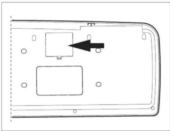
In case it is not possible to establish the power supply over USB (e.g. because of an overload of the host computer due to several USB devices connected), it is also possible to operate the UMX250 with three 1.5-Volt batteries (type "AA", see Fig.1.2).
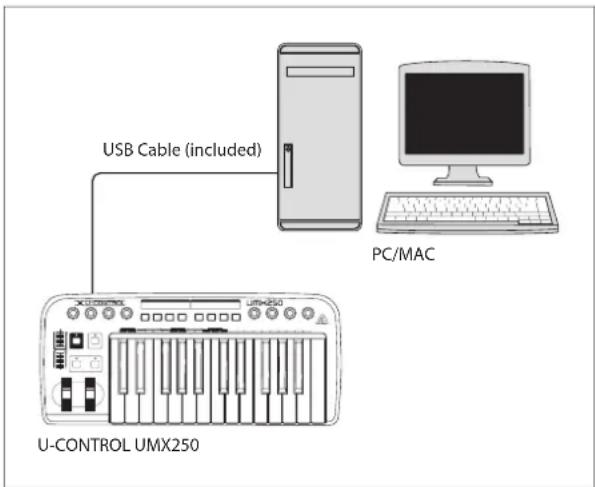
Fig. 1.1: Power supply via USB
natural_image
Diagram of a device casing with internal components and an arrow indicating direction (no text or symbols)Figure 1.2: The battery compartment on the bottom side of the UMX250
Open the battery compartment by pressing the shutter clamp carefully in the direction of the battery compartment, while pulling the cover of the compartment upwards.
Please note the following points when inserting the batteries:
The +symbol of the batteries must coincide with the +symbol of the compartment! Incorrect polarity will damage the electronics!
Do not mix old and new batteries! When you change the batteries, always change all 3 batteries at the same time.
Do not use damaged batteries. The UMX250 could be damaged due to the • leakage of chemicals.
If you do not use the unit for an extended period of time, please remove the • batteries from the compartment. Here again, the batteries could leak and damage the device.
After inserting the batteries, please close the battery compartment and make sure the shutter clamp snaps into place again.
If you do neither want to connect the power supply over USB nor operate the unit with batteries, there is yet another possibility to connect the UMX250 over an external power pack. Please observe the correct operational data (DC 9 V; 100 mA) and correct polarity of the connector plug; you will find information about this above the DC input on the rear of the unit. Reverse polarity can damage the electronics.
1.3 Online registration
Please register your new BEHRINGER equipment right after your purchase by visiting http://behringer.com and read the terms and conditions of our warranty carefully.
Should your BEHRINGER product malfunction, it is our intention to have it repaired as quickly as possible. To arrange for warranty service, please contact the BEHRINGER retailer from whom the equipment was purchased. Should your BEHRINGER dealer not be located in your vicinity, you may directly contact one of our subsidiaries. Corresponding contact information is included in the original equipment packaging (Global Contact Information/European Contact Information). Should your country not be listed, please contact the distributor nearest you. A list of distributors can be found in the support area of our website (http://behringer.com).
Registering your purchase and equipment with us helps us process your repair claims more quickly and efficiently.
Thank you for your cooperation!
EN
System requirements1.4
For USB operation, a current WINDOWS PC or MAC with a USB connection is sufficient. Both USB 1.1 and USB 2.0 are supported.
The UMX250 supports the USB MIDI compatibility of WINDOWS XP, ◇ Vista and MAC OS X operating systems.
The UMX250 can also be operated as a stand-alone MIDI controller with no PC connected. Software control via MIDI is also possible, provided your computer has a MIDI interface.
Introduction to MIDI2.
MIDI control for beginners2.1
Application possibilities for the UMX models are truly wide-ranging. We'll start with a couple of general explanations and examples that should quickly let you get a good understanding of MIDI basics.
The definition of the MIDI standard began in 1982 with the cooperation of various international companies (MIDI: Musical Instrument Digital Interface). At that time, musicians were looking for a possibility of managing the communication of electronic musical instruments of different makes with one another.
What exactly does the UMX250 do?
Simply put, this is a remote control for all kinds of MIDI equipment. Using the faders, rotary knobs and buttons, the foot pedal and the keyboard, an entire array of control instructions can be generated, which in turn can control the most diverse functions of external devices.
What kinds of equipment can I control with the UMX250?
You can basically control any device supporting the MIDI format. Both hardware and software MIDI devices are controlled in exactly the same way. The only difference is in the wiring.
Here are a couple of suggestions on how you can use your UMX250:
Editing sound parameters of (virtual) synthesizers, sound samplers, GM/GS/XG sound generators.
Controlling parameters on effects equipment/software plug-ins such as effects processors, reverbs, compressors, equalizers.
Remotely controlling software mixers (volume, panorama, mute functions, etc.).
Remotely controlling transport functions (playback, forward, stop, etc.) on sequencers, hard disk recorders, drum computers, etc.
Live control of volume and sound parameters on expanders
Remotely controlling groove boxes, step sequencers, MIDIgenerators ◦ and other "live" software
Program changes and volume control on sound generators (just like on a master keyboard)
Can be used by band keyboardists, solo entertainers, organists, electronic music performers, DJs, sound engineers, home/project studio owners, theater technicians, etc.
And how does it work?
Remote control is realized by assigning the individual control elements of the UMX250 to individual MIDI parameters. Whenever one of these control elements is operated, the UMX250 generates the control data assigned to this control element, which are then transferred to external devices over a data link. Thus, for example, the VOLUME/DATA fader is factory-set to send data controlling the volume level of a channel.
The data connection is usually a standard MIDI cable with a 5-pin DIN plug on each end. Such cables should not exceed a length of 15 meters. With the UMX250 there is one more data connection available: the USB cable to the host computer. Here, the cable should not exceed a length of 5 meters.
The data transmission takes place over 16 channels.
The control data generated by the individual control elements are also called MIDI messages, which can be divided into 3 major groups:
Channel Messages: Here, channel-specific control information is transmitted. An example of a channel message is the note-on instruction. As soon as a key is played on the keyboard of the UMX250, the device generates an instruction which contains the pitch, channel number and velocity. The receiving sound generator "knows" which tone has to be played.
System Messages: These messages are not channel-specific but relate to the entire system to which they are sent. They are divided into 3 groups: System Exclusive Messages (for operating system backup, updates, management of memory contents); System Real-Time Messages (e.g. for remote control of other devices); System Common Messages (e.g. for the synchronization of several devices).
☐ Control Messages: Also known as Control Changes or Controllers, abbreviated as "CC... (Control Change)". There are 128 controllers in total, which are numbered from 0 to 127. Controllers are always channel-specific.
- Please refer to Table 6.1 to find out which type of controller you are currently working with.
- MIDI data are only control data and contain no audible audio information! The data transmission takes place over 16 channels.
What settings do I have to make? Where? How?
Basically, which control element generates which controller must be set on the UMX250, and how incoming controller commands should be interpreted must be set on the receiving device.
Regarding controller assignment, there are two possible principles:
You use the preset controller configuration set in the factory (see Fig. 3.1, [10]). In this case, you only need to make the assignments on the receiving device.
You use your own controller configuration set up in ASSIGN mode. How to assign controllers to the UMX250 is described in Chapter 4 "OPERATION".
USB mode and stand-alone operation2.2
The UMX250 can be operated as a USB interface or stand-alone device. The two modes are different with respect to the MIDI signal flow.
USB mode2.2.1
When the UMX250 is linked via USB to a computer, the signalflow is as shown below (Fig. 2.1).
After the UMX250 has been connected to the host computer, a virtual MIDI IN and MIDI OUT interface is emulated. MIDI data generated in the UMX250 are first sent over the USB interface to the host computer, where they are received at the emulated MIDI IN. A sequencer software running on the host computer receives the MIDI data via the MIDI IN and relays them to the emulated MIDI OUT—if all sequencer parameters are set properly. The data are then sent back to the UMX250 via the USB interfaces on the computer/UMX250, where they are looped through to the physical MIDI OUT [14]. From here, the MIDI data are sent to the devices connected to the MIDI OUT.
The MIDI OUT connector 14 can also be used as a normal MIDI interface, independently of the sequencer software operating the UMX250.
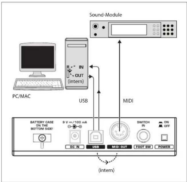
Fig. 2.1: Block diagram of MIDI signal flow
Stand-alone operation2.2.2
When the UMX250 is not linked via USB to a computer, it is automatically set to stand-alone mode. In this case, the UMX250 can only send out MIDI data from its MIDI OUT connector.
Control Elements and Connections3.
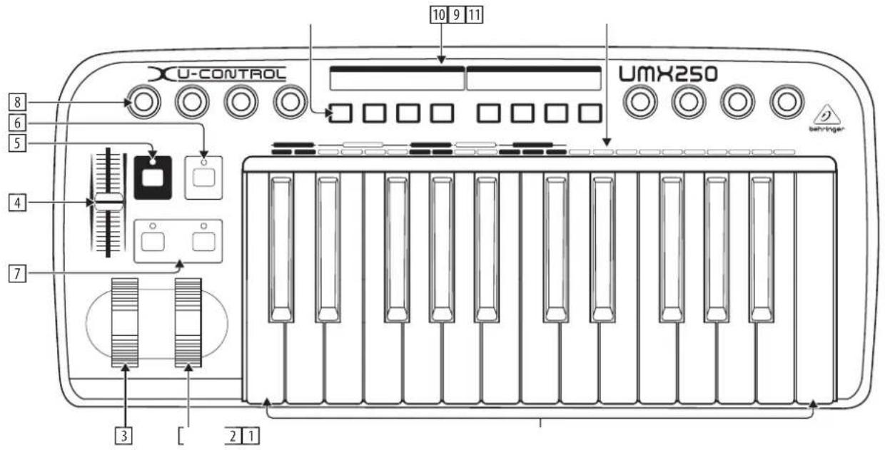
Fig. 3.1: Top view
The following factory settings refer to GLOBAL MIDI channel 1.
The keyboard of the UMX250: 25 large, velocity-sensitive keys for maximum playing comfort. The keyboard not only provides for playing, but also functions as an encoder in the context of the assignment procedure.
The MODULATION wheel functions ex works as a conventional modulation 2 wheel (MIDI CC 1). In ASSIGN mode, any MIDI controller can be assigned to it. When you release the MODULATION wheel, it retains its adjusted value.
The PITCH BEND wheel is normally used to change the pitch in real time. In this way, a sound can be "bent" upwards/downwards by several semitones while playing. The specific amount of pitch bending applied to a sound can be set on the device controlled by the UMX250.
4 Ex works, the VOLUME/DATA fader controls the volume of the notes played on the keyboard (MIDI CC 7). In ASSIGN mode, it can be set to control any MIDI controller.
5 The ASSIGN button allows you to assign different functions to the various control elements.
EN
The basic principle is always the same:
Press the ASSIGN button and keep it pressed. The status LED above the 1) button lights up. The UMX250 signals that it has entered ASSIGN mode.
Select the control element to which you would like to assign a new MIDI 2) function by operating it.
Release the ASSIGN button.3)
Depending on the choice you made, you may have to define an additional 4) value range (see below for more details).
Press the ENTER button on the keyboard to confirm your assignments. 5) To discard your assignments either press the CANCEL button or the ASSIGN button again. In either case, the ASSIGN LED goes out and the UMX250 quits ASSIGN mode.
The USER MEMORY button is used to recall the internal memory. ^[6] The internal memory contains all assignment information set in ASSIGN mode. Any changes that were made after USER MEMORY selection are automatically saved without further user prompts. The USER MEMORY is retained even after the unit is switched off.
The two OCTAVE SHIFT buttons are preset to shift the keyboard range by 7 several octaves up or down. The associated LEDs help you identify the current octave setting (see Table 3.1). Since the OCTAVE SHIFT buttons can also be assigned to any MIDI controller, we would like to refer you to Chapters 4.2.8 and 4.2.9 for detailed information.
The eight high-resolution rotary controls R1 – R8 generate continuous 8 controller information. They are the controllers that are shown above the buttons in the table 10 . All rotary controllers can be assigned to any controller in ASSIGN mode.
The eight buttons B1 – B8 generate switch controllers. Again, these are 9 factory-set functions (see table 10 on the device). Like the rotary controls the buttons can be freely assigned to any controller in ASSIGN mode.
The table shows the controller assignment preset at the factory. ^10
Keyboard legend: Informs you about the special functions performed by [11] individual keys on the keyboard. The individual elements of the keyboard legend are described in detail in Chapter 4 “OPERATION”.
Operation Octave shift LED
| press once | Shift one octave up or down | LED on |
| press 2nd time | Shift 2 octaves up or down | flashing |
| press 3rd time | Shift 3 octaves up or down | flashing |
| press both buttons | Reset (all octave shifts are reversed) | LED off |
Table 3.1: LED activity depending on the OCTAVE SHIFT status

Fig. 3.2: Rear panel connectors
12 Use this socket to supply the UMX250 with current from an external power supply unit (not included).
[13] The USB connector of the UMX250. The connector (type B) on the device is connected using the cable supplied to a free slot on the host computer (where you will find a type A connector). It is compatible with the USB 1.1 and USB 2.0 standards.
14 In addition to the connection to the computer, you can use the MIDI OUT to connect additional MIDI devices, so that the UMX250 transforms into a fully-featured, easily accessible MIDI interface for your host computer.
15 Use the FOOT SWITCH connector to connect a sustain pedal. This port is factory-set and assigned to the MIDI parameter "Foot Pedal" (CC 64), which represents a switch controller. When the pedal is pressed (and held) in normal Play mode, it generates a controller with the value 127. When the pedal is released, the controller falls back to 0 (typical piano sustain pedal behavior). Apart from that the pedal assignment is the same as the button assignment, i.e. you can assign any MIDI controller to it.
16 The POWER switch is used to switch the unit on and off.
Please close all programs if you want to switch off the UMX250 while the computer is running or terminate the USB connection.
4. Operation
In the following, we will explain the operation of the UMX250 in detail. Please note the differentiation between buttons (see control elements 9) and keys (control element 1)! Please do not confuse these!
4.1 PLAY mode
After power-up the UMX250 is in PLAY mode. You can start playing, modify filter sweeps with the rotary controls, determine program changes intuitively, realize panorama changes, controlsoft synths, and so on.
4.1.1 The FACTORY MEMORY
The FACTORY MEMORY is the internal memory storing the basic settings of the UMX250. The most important feature of the FACTORY MEMORY is the controller map described in point 10. These settings define a number of useful parameters and are automatically loaded when the device is switched on.
Assignments that are modified during a session, will be discarded when the unit is switched off. In order to save the modified assignments, the UMX250 has been provided with a USER MEMORY.
4.1.2 The USER MEMORY
Settings that are stored in the USER MEMORY, are stored permanently in the internal flash ROM and will be retained even after switching the unit off.
Change to the USER MEMORY by pressing button 6. When you access the USER MEMORY for the first time, it stores a copy of the FACTORY MEMORY settings. As soon as you make changes to the existing controller map, they are stored automatically without your intervention.
The following control element assignments including channel information can be permanently stored in the USER MEMORY:
- FOOT SWITCH connector
- OCTAVE SHIFT button
• VOLUME/DATA fader - PITCH BEND wheel
- MODULATION wheel
• Rotary controls R1 – R8 - Buttons B1 – B8
ASSIGN mode 4.2
As already mentioned in the preceding chapters, the ASSIGN mode is a powerful tool which allows you to re-configure the UMX250 to an extremely easy-to-use controller.
The fundamental logic of the assignment procedure was already presented in Chapter 3 "Control elements and connections".
Setting the GLOBAL CHANNEL4.2.1
MIDI channels are classified into two types: one GLOBAL CHANNEL and 16 SINGLE CHANNELS.
The GLOBAL MIDI CHANNEL is a factory setting and all MIDI instructions are sent over this channel: messages of various control elements as well as note-on and note-off messages. Please proceed as follows to modify the GLOBAL MIDI CHANNEL:
Press the ASSIGN button and keep it pressed.1)
Press the GLOBAL key.2)
Release the ASSIGN button.3)
Now define the GLOBAL CHANNEL by entering a number between 1 and 16 4) using the number keys. If you enter a number greater than 16, your entry will be rejected.
Examples:
• If you want to enter channel 14, press keys 1 and 4.
To enter channel 7 press key • 7
In order to confirm your selection, press the ENTER key. To discard your 5) assignments either press the CANCEL button or the ASSIGN button again. In either case the ASSIGN LED goes out.
Ex works the GLOBAL CHANNEL is set to channel 1.
4.2.2 Individual channel assignment
The assignment of individual control elements to a certain channel is useful if you want to control external devices independently of one another.
Example:
You play synthesizer A over channel 2 from the keyboard, while synthesizer B is controlled on channel 5 by a sequencer software. Now you can control the filter frequency of device B in real time using one of the eight rotary controls, and at the same time continue playing device A without changes to the filter frequency.
Press the ASSIGN button and keep it pressed.1)
2) Operate the control element whose channel shall be set to differ from the GLOBAL CHANNEL. If it is a controller or a fader, move it briefly. If it is a button, press it once. Now the UMX250 "knows" which control element shall be assigned to a SINGLE CHANNEL.
Release the ASSIGN button.3)
4) Press the SINGLE key.
5) Now define the SINGLE CHANNEL by entering a number between 1 and 16 using the number keys. If you enter a number greater than 16, your entry will be rejected.
Example:
• If you want to enter channel 11, press keys ☐ and ☐.
• To enter channel 4 press key 4.
☐ Special case: If you want to assign the control element to the GLOBAL CHANNEL again, please press the 0 key next to the ENTER key (instead of the number keys 1 to 9).
6) To finalize your settings, press the ENTER button. To discard your assignments either press the CANCEL button or the ASSIGN button again. In either case the ASSIGN LED goes out.
The channel set-up of all control elements of the UMX250 is based on the GLOBAL CHANNEL. This means that a control element is always set to the GLOBAL CHANNEL until you assign a different channel to it. Whenever you change the GLOBAL CHANNEL you also change the channels assigned to the various control elements!
4.2.3 GLOBAL CHANNEL assignment
In comparison to the procedure described in the previous chapter, the advantage of the method shown here is that you have to press fewer buttons to make adjustments.
Press the ASSIGN button and keep it pressed.1)
2) Operate the control element whose GLOBAL CHANNEL shall be set. Release the ASSIGN button.3)
4) Press the SINGLE-key.
5) Press the 0-key.
6) Press ENTER to confirm. Press CANCEL or the ASSIGN button again to discard your assignments. In either case the ASSIGN LED goes out.
4.2.4 The PANIC key combination
Imagine you have already worked several hours on a song and suddenly one of your sound modules produces a "hanging note". If you execute a PANIC instruction, a sound module receiving this instruction will be muted immediately.
Press the ASSIGN button and keep it pressed.1)
2) Press RESET ALL or NOTES OFF.
3) Release the ASSIGN button. The device automatically enters Play mode again.
The instruction chosen will be sent immediately after pressing one of the two buttons mentioned above.
4.2.5 The SNAPSHOT SEND command
The SNAPSHOT command transmits all parameters including their current values: all control element assignments as well as the current channel settings are sent out from the MIDI OUT connector and the USB output of the UMX250.
In this way it is possible to transmit the entire UMX250 mapping to a sequencer software at the beginning of a song. The song can then be played back with the final controller values adjusted for it. If the parameters of an external device have been changed, you can also use SNAPSHOT to correct the values.
Press the ASSIGN button and keep it pressed.1)
2) Press the SNAP SEND key.
3) Release the ASSIGN button. The device automatically enters Play mode again.
The SNAPSHOT command is sent immediately after playing the keyboard.
EN
Local off4.2.6
The effect of LOCAL OFF is that any data entries made with the control elements will NOT be passed on to the MIDI OUT connector or the USB OUT. In LOCAL OFF mode you can, for example, re-adjust the rotary controls without sending any information to the external devices connected—which would normally be the case.
Press the ASSIGN button and keep it pressed.1)
Release the ASSIGN button and adjust the control elements as required.3)
Finalize your selection with ENTER, CANCEL or ASSIGN. In either case the 4) ASSIGN LED goes out and the UMX250 enters Play mode again.
Control elements assignment4.2.7
In Chapter 4.2.2 we described how to assign an individual channel to each control element. Here you will learn how to assign new controllers.
This procedure applies to the MODULATION wheel, the DATA/VOLUME fader, the rotary controls R1 – R8, the buttons B1 – B8 and to the optional sustain pedal connected to jack 19.
Press the ASSIGN button and keep it pressed.1)
Move or press the corresponding controller or button respectively, or hold 2) down the sustain pedal.
Release the ASSIGN button.3)
Press the number keys on the keyboard to enter the controller number of 4) your choice. Only values between 0 and 127 can be entered. Higher values are ignored by the device.
Examples:
• To enter CC 14 press keys 1 and 4.
• If you want to select CC 107, press 1, 0 and 7.
5) Press ENTER to confirm. To discard your assignments either press the CANCEL button or the ASSIGN button again. In either case the ASSIGN LED goes out.
Please note two special cases with regard to a button or the sustain pedal:
If you assign CC 07 (Channel Volume) to a button, the channel volume "0" is sent each time you press the button. This will always mute the channel, which is a very interesting feature when playing live.
If you use the controller CC 10 (Panorama) for the buttons or sustain pedal, pressing the control element will send out a value of 64. As a consequence, the channel will always be set to center position in the stereo panorama.
4.2.8 Program and bank change
The UMX250 provides three options to change programs on external devices.
This is a very powerful function which allows you to fully exploit the multitude of functions of your sound modules.
Options a) and b) allow you to select any programs using a defined selection procedure. Option c) speeds up the procedure, so that you can select programs at the touch of a button.
a) If you are sure to select only one of 128 different programs, you can effect program changes in ASSIGN mode as shown below. However, if the number of 128 is exceeded, you will have to use the procedure described in section b).
Press the ASSIGN button and keep it pressed.1)
2) Press the SINGLE key.
Release the ASSIGN button.3)
Now define the SINGLE CHANNEL by entering a number from 1 to 16 using 4) the number keys. In order to assign the GLOBAL CHANNEL, please press the 0 instead.
6) Press the number keys on the keyboard to enter the program number of your choice. Only values between 0 and 127 can be entered. Higher values are ignored by the device.
Examples:
• To enter program 15, press keys 1 and 5
• If you want to select program 127, press 1, 2 and 7.
7) Confirm your selection with ENTER. If you do not like the selected program, discard your selection with CANCEL or press the ASSIGN button again. In either case, the ASSIGN LED goes out.
If you want to make a selection from more than 128 programs, b) please use the following program change procedure. In this case your programs will be organized in banks, which can be selected with a special MIDI instruction called BANK SELECT. Here's how it works:
The BANK SELECT instruction consists of two parts: one MSB part and one LSB part.
The MSB part describes a value range comprising 128 different values. On many devices this is the more important part of the BANK SELECT instruction.
The LSB part describes each of the 128 MSBs using 128 additional single steps. In both cases the numbering is from 0 to 127.
In total, the BANK SELECT instruction offers the enormous value range of 128 x 128 = 16,384 different values. In theory, this means that you could use external devices with as many different banks. Considering the fact that each single bank includes another 128 single programs, you get the unbelievably large number of 2,097,152 programs for you to organize.
Press the ASSIGN button and keep it pressed.1)
2) Press the SINGLE key.
Release the ASSIGN button.3)
Now define the SINGLE CHANNEL by entering a number from 1 to 16 using 4) the number keys (as described in chapter 4.2.2). In order to assign the GLOBAL CHANNEL, please press ☐ instead.
5) Press the BANK MSB key. Press the number keys on the keyboard to enter the BANK MSB number of your choice. Only values between 0 and 127 can be entered. Higher values are ignored by the device. The BANK MSB is now defined.
Examples:
• To enter MSB 14, press keys (1) and (4).
• If you want to select MSB 107, press (1), (0) and (7).
Now define the BANK LSB by pressing the BANK LSB key. Use the procedure 6) described above to enter the BANK LSB value (see step 5). The entry follows the same rules as were described for the BANK MSB. In steps 5 and 6 you have defined the bank from which the desired program will be selected. Now define the program itself:
Press the PROGRAM key followed by the number keys on the keyboard to 7) enter the program number of your choice. Only values between 0 and 127 can be entered. Higher values are ignored by the device. That's all!
Confirm your selection with ENTER. To discard your assignments either press 8) the CANCEL key or the ASSIGN button again. In either case, the ASSIGN LED goes out.
Example:
You want to use the UMX250 to select preset #49 in bank #25 on an external device over channel 14. Since the bank number of sound modules is often smaller than 128, only the LSB is used to define the bank. The MSB is 0 in this case.
Press the ASSIGN button and keep it pressed.1)
Press the SINGLE key.2)
Release the ASSIGN button.3)
4) Define the MIDI channel by pressing keys 1 and 4.
5) Press the BANK MSB key and then ☐.
6) Press the BANK LSB key and then keys 2 and 5 to select bank #25.
7) Define the program by pressing the PROGRAM key followed by keys 4 and 9 to select program #49.
8) Press the ENTER key.
c) Direct program selection using the OCTAVE SHIFT buttons.
Press the ASSIGN button and keep it pressed.1)
2) Press the one of the two OCTAVE SHIFT buttons to which you want to assign the program change function.
Release the ASSIGN button.3)
4) Press the PROG DIR key. Press the number keys on the keyboard to enter the preset number of your choice. Only values between 0 and 127 can be entered. Higher values are ignored by the device.
Confirm your selection with ENTER. To discard your assignments either press 5) the CANCEL key or the ASSIGN button again. In either case the ASSIGN LED goes out.
If you have not yet assigned an individual MIDI channel to the OCTAVE SHIFT buttons (see Chapter 4.2.2), the direct selection of programs always refers to the GLOBAL CHANNEL!
As soon as you have assigned the direct program selection feature to one of the two OCTAVE SHIFT buttons, pressing both buttons simultaneously will do NOTHING at all!
4.2.9 Other functions of the OCTAVE SHIFT buttons
After power-up, the OCTAVE SHIFT buttons are set to their initial state (see Table 3.1 on page 7). In addition to the program change and octave shift functions already described, you can assign a few special functions to the OCTAVE SHIFT buttons in ASSIGN mode:
a) Transposition by single half-tones
b) Scrolling in program libraries
c) Various controller functions:
As soon as a function has been assigned to one of the two buttons, the second button automatically performs the same function—however with limited functionality. As long as you have not assigned a particular function to this button in ASSIGN mode, it will not send any data.
a) Transposition by single semitones:
Press the ASSIGN button and keep it pressed.1)
2) Press the TRANSP +/- key.
Release the ASSIGN button.3)
Confirm your selection with ENTER. To discard your assignments either press 4) the CANCEL key or the ASSIGN button again.
Pressing the right-hand button transposes the pitch up by one half-tone, pressing the left-hand button transposes the pitch down by one semitone. Pressing both buttons simultaneously cancels any transposition made before.
According to the MIDI standard, a keyboard comprises a maximum of 128 semitones. When you reach the lower and upper limits of this range using the transpose function, any further keypress will not raise or lower the pitch any more. This also applies to the transposition by octaves.
Scrolling in program libraries:b)
Most sound modules allow you to store presets in a separate bank, often referred to as user bank. If the order of the songs to be played during a gig is fixed, you can use the user bank to store all sounds used in concert one after the other and concentrate entirely on your performance. Thanks to the OCTAVE SHIFT buttons you don't have to bother any more with searching sounds in your various sound modules.
Press the ASSIGN button and keep it pressed.1)
2) Press the PROG +/- key.
Release the ASSIGN button.3)
Confirm your selection with ENTER. To discard your assignments either press 4) the CANCEL key or the ASSIGN button again.
Pressing the right-hand OCTAVE SHIFT button switches the presets up by one number on the external sound module, pressing the left-hand OCTAVE SHIFT button switches the presets down by one number. Pressing both buttons simultaneously switches back to preset 0 in the current bank.
Remember to assign the OCTAVE SHIFT buttons to an individual MIDI channel if you do not want to use the GLOBAL CHANNEL (see Chapter 4.2.2).
When using the stepwise search function, the channel assignment involves both buttons. Assigning an individual channel to one of the two buttons is not supported.
c) Various controller functions:
Please note that the OCTAVE SHIFT buttons generate switch controller information if assigned to a controller. They always generate a value of 0 or 127.
☐ Two exceptions: If you assign the OCTAVE SHIFT buttons to controller CC 07 (Channel Volume), pressing either of the two buttons generates the value 0. With controller CC 10 (Panorama), the value generated by pressing either of the buttons is 64.
Please note that when a controller has been assigned, pressing both buttons simultaneously has no effect.
Press the ASSIGN button and keep it pressed.1)
2) Press the one of the two OCTAVE SHIFT buttons to which you want to assign a controller.
EN
Release the ASSIGN button.3)
Press the number keys on the keyboard to enter the controller number of 4) your choice (as described in Chapter 4.2.7).
Confirm your selection with ENTER. To discard your assignments either press 5) the CANCEL key or the ASSIGN button again. In either case the ASSIGN LED goes out.
Remember to assign the OCTAVE SHIFT buttons to an individual MIDI channel if you do not want to use the GLOBAL CHANNEL (see Chapter 4.2.2).
Velocity sensitivity4.2.10
The sensitivity of the UMX250 can be regulated so that the velocity of the keys has an effect on the volume level.
Press the ASSIGN button and keep it pressed.1)
Use the number keys to enter the keyboard velocity (see Table 4.1).2)
Release the ASSIGN button.3)
Confirm your selection with ENTER. To discard your assignments either press 4) the CANCEL key or the ASSIGN button again.
| KEY | EFFECT ON KEY VELOCITY |
| 0 | OFF: velocity value is fixed to 110.Change of key pressure has no effect on volume level. |
| 1 | SOFT: key pressure is very sensitive; low velocity changes create high changes in volume level |
| 2 | MEDIUM: key pressure is “normal”; (very) hard hit notes are (very) loud, (very) soft hit notes produce (very) low volume |
| 3 | HARD: key pressure is more unsusceptible compared to all other settings |
| 4to9 | invalid input |
Table 4.1: Effect of RANGE definition on keyboard velocity
The FACTORY RESET command4.2.11
Please proceed as follows to reset all UMX250 settings to their factory defaults:
1) Press the ASSIGN button and keep it pressed.
2a) Press both OCTAVE SHIFT buttons for a temporary FACTORY RESET. All currently modified control elements will be reset to their factory defaults. However, the USERMEMORY remains as before and is not reset!
2b) Press keys (8), (9) and (0) simultaneously for a complete FACTORY RESET: Now not only the control elements of the FACTORY MEMORY but also those of the USER MEMORY will be overwritten.
3) Release the ASSIGN button. The ASSIGN LED stays on.
4) Confirm your selection with ENTER. If you do not want to RESET the unit, either press the CANCEL key or the ASSIGN button again.
5. Specifications
USB Connections
| Type | Type B; USB1.1 |
MIDI Connections
| Type | 5-pin DIN plug OUT |
Control Elements
| Controller | 1 control wheel with center reset1 control wheel without center reset8 rotary knobs1 fader |
| Buttons | 12 buttons |
| Keyboard | 25 keys; velocity-sensitive |
Switch Plug
| Foot pedal | 14 " mono jack with automatic polarity recognition |
Power Supply
| USB | |
| Battery | 3 x 1.5 Volt Mignon (Type "AA") |
| Power connector | 2 mm DC jack, negative center 9 V, 100 mA regulatedUSA/Canada 120 V~, 60 HzChina/Korea 220 V~, 50 HzUK/Australia 230 V~, 50 HzEurope 230 V~, 50 HzJapan 100 V~, 50-60 Hz |
| Power consumption | max. 0.9 W |
Dimensions/Weight
| Dimensions (H x W x D) | approx. 8 1532 x 3 2632 x 19 1532 " approx. 215 x 97 x 495 mm |
| Weight | approx. 4 3032 lbs. / 2.24 kg |
BEHRINGER is constantly striving to maintain the highest professional standards. As a result of these efforts, modifications may be made from time to time to existing products without prior notice. Specifications and appearance may differ from those listed or illustrated.
Appendix 6.
EN
Standard MIDI Controller (CC) Numbers
| 00 | Bank Select | 32 | Bank Select LSB | 64 | Damper Pedal (Sustain) | 96 | Data Entry +1 (Increment) |
| 01 | Modulation | 33 | Modulation LSB | 65 | Portamento On/Off | 97 | Data Entry -1 (decrement) |
| 02 | Breath Controller | 34 | Breath Controller LSB | 66 | Sostenuto On/Off | 98 | NRPN LSB |
| 03 | Controller 3 (undefined) | 35 | Controller 35 (undefined) | 67 | Soft Pedal On/Off | 99 | NRPN MSB |
| 04 | Foot Controller | 36 | Foot Controller LSB | 68 | Legato Footswitch | 100 | RPN LSB |
| 05 | Portamento Time | 37 | Portamento Time LSB | 69 | Hold 2 | 101 | RPN MSB |
| 06 | Data Entry MSB | 38 | Data Entry LSB | 70 | Sound Controller 1 (Sound Variation) | 102 | Controller 102 (undefined) |
| 07 | Channel Volume (formerly Main Volume) | 39 | Channel Volume LSB (formerly Main Volume) | 71 | Sound Controller 2 (Resonance/Timbre) | 103 | Controller 103 (undefined) |
| 08 | Balance | 40 | Balance LSB | 72 | Sound Controller 3 (Release Time) | 104 | Controller 104 (undefined) |
| 09 | Controller 9 (undefined) | 41 | Controller 41 (undefined) | 73 | Sound Controller 4 (Attack Time) | 105 | Controller 105 (undefined) |
| 10 | Pan | 42 | Pan LSB | 74 | Sound Controller 5 (Cutoff Frequency/Brightness) | 106 | Controller 106 (undefined) |
| 11 | Expression | 43 | Expression LSB | 75 | Sound Controller 6 (Decay Time) | 107 | Controller 107 (undefined) |
| 12 | Effect Control 1 | 44 | Effect Control 1 LSB | 76 | Sound Controller 7 (Vibrate Rate) | 108 | Controller 108 (undefined) |
| 13 | Effect Control 2 | 45 | Effect Control 2 LSB | 77 | Sound Controller 8 (Vibrate Depth) | 109 | Controller 109 (undefined) |
| 14 | Controller 14 (undefined) | 46 | Controller 46 (undefined) | 78 | Sound Controller 9 (Vibrate Delay) | 110 | Controller 110 (undefined) |
| 15 | Controller 15 (undefined) | 47 | Controller 47 (undefined) | 79 | Sound Controller 10 (undefined) | 111 | Controller 111 (undefined) |
| 16 | General Purpose 1 | 48 | General Purpose 1 LSB | 80 | General Purpose 5 | 112 | Controller 112 (undefined) |
| 17 | General Purpose 2 | 49 | General Purpose 2 LSB | 81 | General Purpose 6 | 113 | Controller 113 (undefined) |
| 18 | General Purpose 3 | 50 | General Purpose 3 LSB | 82 | General Purpose 7 | 114 | Controller 114 (undefined) |
| 19 | General Purpose 4 | 51 | General Purpose 4 LSB | 83 | General Purpose 8 | 115 | Controller 115 (undefined) |
| 20 | Controller 20 (undefined) | 52 | Controller 52 (undefined) | 84 | Portamento Control | 116 | Controller 116 (undefined) |
| 21 | Controller 21 (undefined) | 53 | Controller 53 (undefined) | 85 | Controller 85 (undefined) | 117 | Controller 117 (undefined) |
| 22 | Controller 22 (undefined) | 54 | Controller 54 (undefined) | 86 | Controller 86 (undefined) | 118 | Controller 118 (undefined) |
| 23 | Controller 23 (undefined) | 55 | Controller 55 (undefined) | 87 | Controller 87 (undefined) | 119 | Controller 119 (undefined) |
| 24 | Controller 24 (undefined) | 56 | Controller 56 (undefined) | 88 | Controller 88 (undefined) | 120 | All Sound Off |
| 25 | Controller 25 (undefined) | 57 | Controller 57 (undefined) | 89 | Controller 89 (undefined) | 121 | Reset All Controllers |
| 26 | Controller 26 (undefined) | 58 | Controller 58 (undefined) | 90 | Controller 90 (undefined) | 122 | Local Control On/Off |
| 27 | Controller 27 (undefined) | 59 | Controller 59 (undefined) | 91 | Effects 1 Depth (Reverb) | 123 | All Notes Off |
| 28 | Controller 28 (undefined) | 60 | Controller 60 (undefined) | 92 | Effects 2 Depth (Tremolo) | 124 | Omni Mode Off |
| 29 | Controller 29 (undefined) | 61 | Controller 61 (undefined) | 93 | Effects 3 Depth (Chorus) | 125 | Omni Mode On |
| 30 | Controller 30 (undefined) | 62 | Controller 62 (undefined) | 94 | Effects 4 Depth (Celeste/Detune) | 126 | Poly Mode Off/Mono Mode On |
| 31 | Controller 31 (undefined) | 63 | Controller 63 (undefined) | 95 | Effects 5 Depth (Phaser) | 127 | Poly Mode Off/Mono Mode On |
Table 6.1
FEDERAL COMMUNICATIONS COMMISSION COMPLIANCE INFORMATION

BEHRINGER
U-CONTROL UMX250
Responsible party name: MUSIC Group Services USA, Inc.
Address: 18912 North Creek Parkway,
Suite 200 Bothell, WA 98011, USA
Phone/Fax No.: Phone: +1 425 672 0816
Fax: +1 425 673 7647
U-CONTROL UMX250
complies with the FCC rules as mentioned in the following paragraph:
This equipment has been tested and found to comply with the limits for a Class B digital device, pursuant to part 15 of the FCC Rules. These limits are designed to provide reasonable protection against harmful interference in a residential installation. This equipment generates, uses and can radiate radio frequency energy and, if not installed and used in accordance with the instructions, may cause harmful interference to radio communications. However, there is no guarantee that interference will not occur in a particular installation. If this equipment does cause harmful interference to radio or television reception, which can be determined by turning the equipment off and on, the user is encouraged to try to correct the interference by one or more of the following measures:
- Reorient or relocate the receiving antenna.
- Increase the separation between the equipment and receiver.
- Connect the equipment into an outlet on a circuit different from that to which the receiver is connected.
- Consult the dealer or an experienced radio/TV technician for help.
This device complies with Part 15 of the FCC rules. Operation is subject to the following two conditions:
(1) this device may not cause harmful interference, and
(2) this device must accept any interference received, including interference that may cause undesired operation.
Important information:
Changes or modifications to the equipment not expressly approved by MUSIC Group can void the user's authority to use the equipment.

natural_image
Black-and-white photo of a person in motion, possibly playing a dynamic pose (no visible text or symbols)imagine music


- U-CONTROL UMX250
- EN
- Table of Contents
- Thank you
- Important Safety Instructions
- CAUTION
- ATTENTION
- Legal Disclaimer
- Limited Warranty
- § 1 Warranty
- § 2 Online registration
- § 3 Return materials authorization
- Warranty Exclusions§ 4
- § 5 Warranty transferability
- § 6 Claim for damage
- § 7 Limitation of liability
- § 8 Other warranty rights and national law
- § 9 Amendment
- Before you get Started1.
- Shipment1.1
- Initial operation and power supply1.2
- Online registration
- System requirements1.4
- Introduction to MIDI2.
- MIDI control for beginners2.1
- What exactly does the UMX250 do?
- What kinds of equipment can I control with the UMX250?
- And how does it work?
- What settings do I have to make? Where? How?
- USB mode and stand-alone operation2.2
- USB mode2.2.1
- Stand-alone operation2.2.2
- Control Elements and Connections3.
- Operation
- PLAY mode
- The FACTORY MEMORY
- The USER MEMORY
- ASSIGN mode 4.2
- Setting the GLOBAL CHANNEL4.2.1
- Examples:
- Individual channel assignment
- Example:
- GLOBAL CHANNEL assignment
- The PANIC key combination
- The SNAPSHOT SEND command
- Local off4.2.6
- Control elements assignment4.2.7
- Program and bank change
- Other functions of the OCTAVE SHIFT buttons
- Scrolling in program libraries:b)
- Velocity sensitivity4.2.10
- The FACTORY RESET command4.2.11
- Specifications
- Appendix 6.
- FEDERAL COMMUNICATIONS COMMISSION COMPLIANCE INFORMATION
- Important information:
Brand : BEHRINGER
Model : U-Control UMX250
Category : MIDI Keyboard