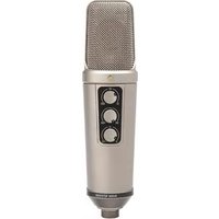
NT2000 - Microphone RODE - Free user manual and instructions
Find the device manual for free NT2000 RODE in PDF.


| Product Type | Large Diaphragm Condenser Microphone |
| Brand | Rode |
| Model | NT2000 |
| Dimensions (Length x Diameter) | 188 mm x 52 mm |
| Weight | 520 g |
| Power Requirement | 48V Phantom Power |
| Frequency Response | 20 Hz - 20 kHz |
| Polar Patterns | Continuously Variable (Omnidirectional, Cardioid, Figure-8) |
| Pad | -10 dB |
| High-Pass Filter | 80 Hz |
| Output Connector | XLR (3-pin) |
| Maximum SPL | 137 dB SPL (with pad) |
| Signal-to-Noise Ratio | 80 dB |
| Self-Noise | 14 dBA |
| Capsule | 1-inch Gold Sputtered |
| Finish | Matte Black |
| Included Accessories | Stand Mount, Foam Windscreen, Zippered Pouch |
| Maintenance & Cleaning | Wipe with dry cloth; store in dry environment |
| Safety | Use with 48V phantom power only; avoid moisture |
| Repairability & Spare Parts | Contact Rode authorized service centers |
| General Information | Studio quality microphone with variable polar patterns |
Frequently Asked Questions - NT2000 RODE
User questions about NT2000 RODE
0 question about this device. Answer the ones you know or ask your own.
Ask a new question about this device
Download the instructions for your Microphone in PDF format for free! Find your manual NT2000 - RODE and take your electronic device back in hand. On this page are published all the documents necessary for the use of your device. NT2000 by RODE.
USER MANUAL NT2000 RODE
natural_image
Close-up of a metallic analog microphone with visible grille and control buttons (no text or symbols)RODETUDIO CONDENSER MICROPHONES

CE (EMC, LVD)
THE NT2000
Serial Number: ....
Checked by: ....
I want to thank you for choosing the NT2000 studio condenser microphone.
Please take a few moments to read this information booklet before using the NT2000, as it will help you gain the best long-term performance from this microphone.
We are very proud of the NT2000. This microphone represents the culmination of many years of dedicated research into the art of recording microphone technology.
We use the word ‘art’ because a studio microphone cannot be judged simply by electrical or acoustical measurements alone. While the NT2000 surpasses technical specifications only attained by the superlative class microphones of the world, we at RODE that once you hear this remarkable transducer, you will agree that RODE created a new benchmark by which all others will be judged.

Peter Freedman
Sydney Australia
Specifications
• Acoustic Principle: Externally polarized 25 mm (1") dual diaphragm
• Active Electronics: J-FET impedance converter with bipolar output buffer.
- Pickup Pattern: Multi-pattern (see graphs)
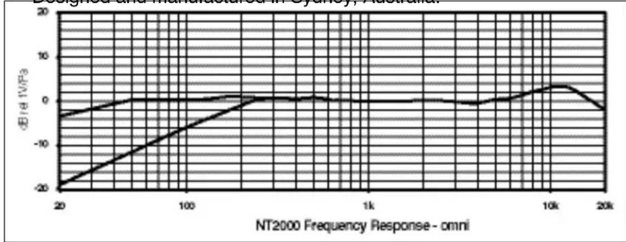
• Frequency Response: 20 Hz \~ 20 kHz (see graph)
• Output Impedance: 200 Ω
• Sensitivity: -36 dB re 1 Volt/Pascal (16 mV @ 94dB SPL) +/- 2 dB
• Equivalent Noise: 7 dBA SPL (per IEC651, IEC268-15)
• Maximum Output: + 15 dBu (@ 1% THD into 1kΩ)
• Dynamic Range: 136 dB (per IEC651, IEC268-15)
• Maximum SPL: 147 dB (@ 1% THD into 1kΩ)
157 dB (@ 1% THD into 1kΩ) with pad at maximum
• Signal/Noise: 84 dB (per IEC651, IEC268-15)
• Power Requirements: Phantom P48 or P24 Volts.
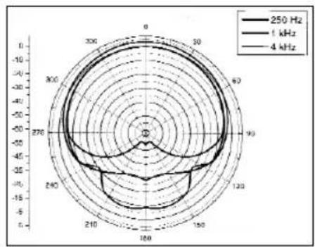
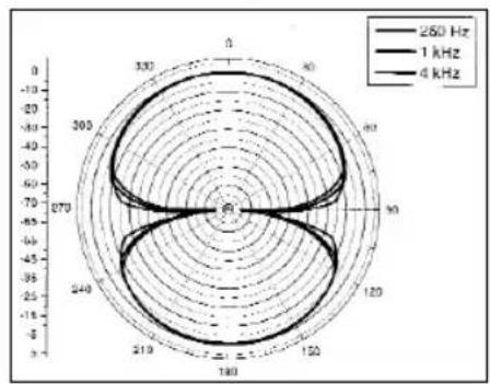
Polar Responses
Cardioid
radar
| Angle (°) | 250 Hz | 1 kHz | 4 kHz | |-----------|--------|-------|-------| | 0 | -10 | -10 | -10 | | 30 | -10 | -10 | -10 | | 60 | -10 | -10 | -10 | | 90 | -10 | -10 | -10 | | 120 | -10 | -10 | -10 | | 150 | -10 | -10 | -10 | | 180 | -10 | -10 | -10 | | 210 | -10 | -10 | -10 | | 240 | -10 | -10 | -10 | | 270 | -10 | -10 | -10 | | 300 | -10 | -10 | -10 |Omni

radar
| Angle | Frequency (Hz) | |---|---| | 0 | 250 | | 30 | 250 | | 60 | 250 | | 90 | 250 | | 120 | 250 | | 150 | 250 | | 180 | 250 | | 210 | 250 | | 240 | 250 | | 270 | 250 | | 300 | 250 | | 330 | 250 | | 360 | 250 |Fig. 8
radar
| Angle | Frequency (Hz) | |---|---| | 0 | 250 | | 90 | 1 kHz | | 180 | 4 kHz | | 270 | 250 | | 360 | 1 kHz | | 460 | 4 kHz | | 550 | 250 | | 640 | 1 kHz | | 730 | 4 kHz | | 820 | 250 | | 910 | 1 kHz | | 1000 | 4 kHz | | 1100 | 250 | | 1200 | 1 kHz | | 1300 | 4 kHz | | 1400 | 250 | | 1500 | 1 kHz | | 1600 | 4 kHz | | 1700 | 250 | | 1800 | 1 kHz | | 1900 | 4 kHz | | 2000 | 250 | | 2100 | 1 kHz | | 2200 | 4 kHz | | 2300 | 250 | | 2400 | 1 kHz | | 2500 | 4 kHz | | 2600 | 250 | | 2700 | 1 kHz | | 2800 | 4 kHz | | 2900 | 250 | | 3000 | 1 kHz | | 3100 | 4 kHz | | 3200 | 250 | | 3300 | 1 kHz | | 3400 | 4 kHz | | 3500 | 250 | | 3600 | 1 kHz |Features
- New Australian designed and manufactured 1" edge terminated, gold sputtered, dual 5 uM diaphragm.
- Continuously variable polar patterns. From omni, through cardioid to figure of eight, controlled at the mic.
• Continuously variable pad.
• Continuously variable high-pass filter.
• Ultra low noise, transformerless SMT circuitry. - Wide dynamic range.
• High strength welded and heat-treated steel mesh head.
• Durable satin nickel finish.
• Internal capsule shock mounting. - Supplied complete with ‘SM2 Shock Mount’ and RC1 Custom Carry Case.
• Designed and manufactured in Sydney, Australia.
line
| NT2000 Frequency Response - omni | ΔE/d 1V/Ω3 | | -------------------------------- | ---------- | | 20 | -20 | | 100 | -10 | | 1k | 0 | | 10k | 5 | | 20k | -5 |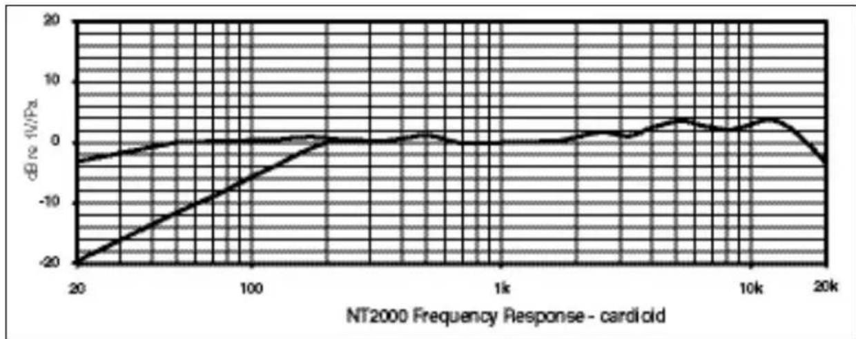
line
| NT2000 Frequency Response - cardiold | dB re-1V/Pa | | ------------------------------------ | ----------- | | 20 | -20 | | 100 | -10 | | 1k | 0 | | 10k | 3 | | 20k | -5 |Accessories:

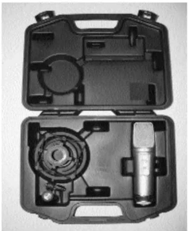
RC1 Custom Carry Case

natural_image
Black mechanical device with structural beams and a handle, no visible text or symbolsSM2 Shock Mount
natural_image
Open black plastic case containing a mechanical device with a central microphone and internal components (no text or symbols visible)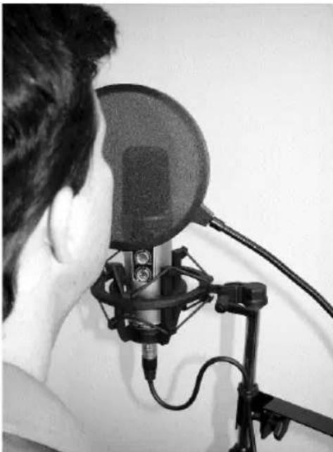
natural_image
Person using a studio microphone setup with adjustable stand (no visible text or symbols)Vocals
We strongly suggest the use of a ‘pop-filter’ for ALL vocal recording. Plosives (‘P’s, ‘B’s and ‘C’s) can produce a sudden jet of air, which can cause the capsule to ‘bottom out’ (overload) and produce a ‘popping’ sound. Pop filters help to prevent the effects of plosives. Moisture on the capsule can cause problems for condenser microphones but the use of a pop filter reduces that risk.
Placement of the microphone and pop filter are important and depend on the volume and style of the vocalist. The best position will be determined only by experiment, but the graphic above may be considered a reasonable starting position.
The ‘proximity effect’ is experienced when close to the microphone and that is evident with an apparent increase in the lower (bass) frequencies. Proper microphone technique can enable good use to be made of this effect. E.g. Intimate, or low-volume phrases can be recorded ‘within proximity’ (closer to the microphone), and louder sections of the performance will be presented from a greater distance. This ‘microphone control’ is of utmost importance when wishing to give expression to a vocal recording.

Piano
To record a piano using a single microphone (see above), that microphone should be placed approximately 60cm (or 2') above the centre of the soundboard, aimed slightly towards the front of the piano.
To record the piano using X/Y Stereo technique, two NT2000's should be angled at 90-110 degrees to each other, over the hammers with one mic aimed towards the lower strings and the other towards the high strings.
The gold dots should be directed down, towards the piano.
An effective stereo ambience may be achieved by recording lower keys on the left and high keys on the right, placing the middle keys around the centre of the recorded sound spectrum.
Drums
There are various ways to record drum kits.
Single microphone ‘overhead’, two microphones overhead (eg X/Y or spaced) and multiple microphones used close to individual drums & cymbals (i.e. close mic'ing):
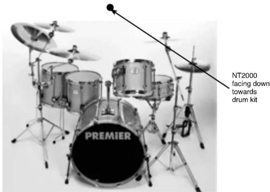
To record a kit with a single microphone, we suggest that you begin by placing the mic' above the centre of the kit at the same height as the kit is wide, with the front of the microphone facing down.
To record the kit with TWO overhead microphones, they should be used at a similar height (as above) and depending on the size of the kit, between 1-2m apart. The mic's would probably be equidistant from the snare drum.
To record a kit using the X/Y stereo technique, two closely matched (similar) microphones should be placed (as above in the single microphone position) with the front of each microphone pointing down, and each at 90-110 degrees to each other.

natural_image
Close-up of an acoustic guitar with a microphone and decorative guitar body (no visible text or symbols)
natural_image
Close-up of a metallic studio microphone on a dark surface, with no visible text or symbols.Acoustic Guitar
A common (single) microphone position when recording acoustic guitar, is between 20 and 30cm away from the front of the instrument where the neck and body meet. Adjust the distance and position to ‘finely’ tune the desired response. This desired response will depend on the instrument, the style of playing and the sound aspired to.
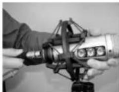
- The NT2000 should be mounted in the SM2 shock mount (Photo 1) which must then be screwed firmly onto a stable microphone stand.
Connect the plug of a microphone cable (Photo 2) firmly and securely to the microphone socket
- We strongly suggest you use a high quality cable with gold-plated connectors. The cable should be as short as possible because long cables may adversely affect sound quality.
A 6 metre cable is a good compromise.
- The gold dot indicates the front of the microphone.

natural_image
Close-up of a robotic arm gripping a metallic tool (no visible text or symbols)Photo 1
natural_image
Close-up of hands operating a mechanical device with a camera and sensor array (no visible text or symbols)Photo 2
There are an infinite number of polar pattern, hi-pass filter and pad settings available on the NT2000. These settings offer ultimate control unlike any other studio microphone available today.
-
Select the preferred polar pattern. The top circular dial on the front of the microphone controls this. (The most common position for regular vocal recording is cardioid – dial set to the 12 o'clock position). When the cardioid position is selected, the microphone picks up sound from the front of the microphone and rejects sound from the rear.
-
When in the omni position (fully anti-clockwise) the microphone picks up sound from all around the microphone and there is less proximity effect. (This is an increase in lower frequencies (bass) when the sound source is ‘closer’ to the microphone). The omni pattern is commonly used for room mic'ing or to record a more natural sound when close mic'ing instruments.
-
When in the figure-of-eight position (fully clockwise), the microphone picks up sound from the front and rear, while rejecting sound from the other two sides. This pattern is commonly used for interviews (2 people using 1 microphone between them) or in conjunction with a cardioid microphone to use the M-S stereo recording technique.
-
You are able to select any position between these three main ‘polar pattern’ settings. For example, if you choose a setting about half way between the omni and cardioid position, you will notice some sound being picked up from the rear of the microphone instead of being almost completely rejected. This can be particularly useful when you require only some sound to be picked up from the rear of the mic but not as much sound from the rear as is present in the omni position.
-
Experiment with the microphone; listen to the various pattern, pad and filter settings and decide what suits your current application best. Allow several seconds for the microphone to stabilize to hear a noticeable difference when adjusting the controls.
You won't damage the microphone no matter which setting you have the three controls in, so go ahead, and try any combination!
The Pad
- This reduces the input level to the microphones in built pre-amp and can be adjusted by moving the lower of the three dials on the microphone. When the dial is in the far left position there is no reduction in level of the recorded source. When the dial is in the far right position, the level of the recorded source is lowered by 10dB.
Any position between 0 and -10dB can be selected.
(NOTE: -3dB reduces the level by 50%)
The pad is useful when recording loud sound sources (such as close-mic'ing drums or amplifiers) to avoid overloading the microphones
The Hi-Pass-Filter
(Middle dial) controls the bass frequencies. This control is sometimes also referred to as a bass-cut because it reduces the selected bass frequency and all frequencies below that.
When the dial is in the far left position there is no reduction of the bass frequencies and so the microphone will deliver a full response.
When the filter is in the far right position, the level is dropped by 3dB at 150Hz and below, which is certainly audible and will have a direct effect on most sound sources. You may choose any setting between 20Hz and 150Hz to cut the level of the selected frequency and below by 3dB. This control is useful for selecting the cut-off point for potentially offending low frequencies (e.g. traffic noise, floor vibrations etc). It can also be used on vocals where you may want a limited response just to be ‘different’.
The best way to set this control is to listen to the microphone while recording the source. If it is vocals for example, set the mic to fully anti-clockwise then - listen to the vocal sound as you start to move the filter to the clockwise position. When you begin to notice the change, turn it back to a lower frequency ‘cut off’ where you can’t hear the difference and you will have the optimum setting for that source. Why is that important? The NT2000 has a very wide response. It will pick up sounds below 20Hz. That’s a good thing if you want to record a church organ or other instruments that reproduce very low bass frequencies, but it can also cause problems when you pick up and record loud low frequencies that have nothing to do with your music. All that does is ‘eat up’ the recording equipments level capability, and reduces clarity.
Remember there are no right or wrong settings; the NT2000 offers you the flexibility to find ‘your sound’. You are now able to record almost anything in any environment the way that you want to.
Settings reminder
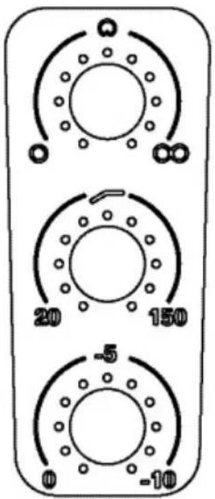
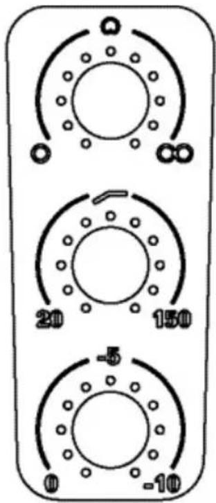
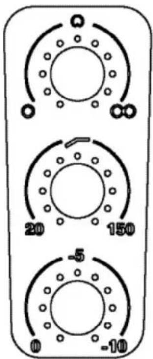
At the back of this manual we have provided a set of control panel graphics. These are available for you to write down the settings you have made during a recording. Should you wish to recreate a section of a recording at any time, or attempt to capture the same “sound quality”, you can refer to the manual and easily retrieve the mics previous settings.
It is important to remember that there are many variables that can affect a microphones sound. The acoustics of the room have a dramatic effect to achieve the same results so you would need to set up in the very same way as you did before with no changes to the room's acoustics. You may also wish to make photocopies of the sheet to allow for future setting records.
We hope the information we have provided helps you get the best from your microphone. If you have any difficulties, please don't hesitate to contact us at: support@rodemic.com
Title:
Date:
Title:
Date:

Title:
Date:
Title:
Date:

Title:
Date:

Title:
Date:
Warranty Service
All RODFucts are warranted for one year from date of purchase and the warranty card should be used to register that purchase.
The warranty covers parts and labour that may be required to repair the microphone during the warranty period. The warranty excludes defects caused by normal wear and tear, modification, shipping damage, or failure to use the microphone as per the instruction guide.
If you experience any problems or have any questions regarding your RODE microphone, first, contact the dealer who sold it to you. If the microphone requires factory authorized service, that dealer will organise return. We have an extensive distributor/dealer network but if you have difficulty getting the advice or assistance you require, do not hesitate to contact us directly or contact your local distributor.
International:
R∅DE Microphones
ABN 91 000 576 483
Unit 2/107 Carnarvon Street
Silverwater NSW 2128 Australia
Ph: 61 2 9648 5855
Fax: 61 2 9648 2455
USA
P.O. Box 3279
Torrance, CA 90510-3279
Ph: 877 328 7456 (Toll Free Within the U.S.)
Ph: 310 328 7456
Fax: 310 328 7180
Technical Support
For information and technical support questions contact:
support@rodemic.com
In the United States and Puerto Rico, contact:
support@rodemic.com
877 3287 7456 toll free, or
310 328 7456
In Australia, contact:
support@rodemic.com
02 9648 5855
Anywhere except Australia, the United States and Puerto Rico, contact:
support@rodemic.com
Australia: 61 2 9648 5855

- THE NT2000
- Specifications
- Polar Responses
- Features
- Accessories:
- Vocals
- Piano
- Drums
- Acoustic Guitar
- The Pad
- The Hi-Pass-Filter
- Settings reminder
- Warranty Service
- International:
- USA
- Technical Support
- In the United States and Puerto Rico, contact:
- In Australia, contact:
- Anywhere except Australia, the United States and Puerto Rico, contact:
Brand : RODE
Model : NT2000
Category : Microphone