
Station Port VIP-811 - Network card / adapter Valcom - Free user manual and instructions
Find the device manual for free Station Port VIP-811 Valcom in PDF.


| Product Type | Network Station Port (VoIP adapter) |
| Model | VIP-811 |
| Network Interface | 1 x RJ-45 (10/100Mbps) |
| Telephone Interface | 1 x RJ-11 (FXS, loop start) |
| Relay Interface | 2 Form C relays (1A @ 24VDC) |
| LED Indicators | Status (power), Link (100Mbps enable), Activity (data) |
| Power Supply Options | PoE (802.3af, Class 3) or external 24VDC barrel connector |
| External Power Connector | 2.5mm barrel jack |
| Dimensions (HxWxD) | 1.38 x 6.13 x 5.25 in (3.50 x 15.6 x 13.33 cm) |
| Weight | 1.25 lbs (0.57 kg) |
| Input Impedance | 600 ohms |
| Output Impedance | 600 ohms |
| Input Level (nominal) | -10 dBm |
| Output Level (nominal) | -10 dBm |
| Relay Contact Rating | 1 A @ 24 VDC |
| Operating Temperature | 0 to +40°C |
| Operating Humidity | 0 to 85% non-precipitating |
| Mounting Options | Wall or table (brackets and rubber pads included) |
| REN (Ringer Equivalence) | 1 |
| Compliance | FCC Part 15 Class A |
Frequently Asked Questions - Station Port VIP-811 Valcom
User questions about Station Port VIP-811 Valcom
0 question about this device. Answer the ones you know or ask your own.
Ask a new question about this device
Download the instructions for your Network card / adapter in PDF format for free! Find your manual Station Port VIP-811 - Valcom and take your electronic device back in hand. On this page are published all the documents necessary for the use of your device. Station Port VIP-811 by Valcom.
USER MANUAL Station Port VIP-811 Valcom
The VIP-811 Networked Station Port allows most loop start terminal devices to be connected to a managed IP-based LAN/WAN.
SPECIFICATIONS
Access Methods
- PBX, FXO Port
- POTS telephone set
Features
• RJ-45 for network connection
• 1 RJ-11 telephone connections
• 2 Relays with Form C contacts
- Front panel activity LED
• Network activity LEDs
• 1 REN
• 2.5mm jack for external power
• Power over Ethernet (PoE) 802.3af compatible
Dimensions/Weight
- 1.38" H x 6.13" W x 5.25" D (3.50cm H x 15.6cm W x 13.33cm D)
• Weight: 1.25 lbs. (0.57 kg)
Nominal Specifications
Input Impedance: 600 Ohms
Input Level: -10dBm
Output Impedance: 600 Ohms
Output Level: - 10dBm nominal
Relay Current: 1 AMP @ 24VDC
Nominal Power Requirements
Via rear panel barrel connector:
Voltage:
Current: 325mA
Via 802.3af PoE Ethernet Switch:
802.3af:
Class
3

Environment
Temperature:
0 to +40°C
Humidity:
0 to 85% non-precipitating
Packing List
| Qty | Item |
| 1 | VIP-811 |
| 1 | VSP Document |
| 2 | Mounting Brackets W/ Hardware |
| 4 | Rubber Pads |
INSTALLATION
NOTE: The telephone system referred to in this manual is the customer premise equipment such as an electronic key system, a PBX or a dedicated single line telephone sets. The VIP-811 is not intended for direct or indirect connection to the public telephone network. When used with a customer premise telephone system such as a key system or PBX system, these units are interfaced to the system via a fully protected trunk port or system central office port, which is a fully protected interface device. Also, the host system must be configured to disallow central office trunk conferencing in order to prevent indirect connection to the public network.
24VDC
Precautionary Designations


FCC Information
This equipment has been tested and found to comply with the limits for a Class A digital device, pursuant to Part 15 of the FCC Rules. These limits are designed to provide reasonable protection against harmful interference when the equipment is operated in a commercial environment. This equipment generates, uses and can radiate radio frequency energy and if not installed and used in accordance with the instruction manual, may cause harmful interference to radio communications. Operation of this equipment in a residential area may cause harmful interference in which case the user will be required to correct the interference at his own expense.
Mounting
The VIP-811 is designed for wall or table mounting.
Table: Provided with the VIP-811 are four rubber pads. Peel the pads from their carrier backing and place at the four corners of the bottom of the unit.
Wall: Using the bracket and screws provided, secure the VIP-811 to the wall.

Power Connections
The preferred method of powering a VIP-811 is via a power over Ethernet switch meeting the 802.3af specification.
If the rear panel barrel connector is used for power, the preferred power supply is a Valcom VIP-324D.
Make all required signal connections before applying power to the unit. If powering via 802.3af, make sure all signal connections via the rear panel are made then connect the VIP-811 to the Ethernet switch.
If power is supplied via the barrel connector, make sure all signal connections are secure. Attach the unit to the network via the front panel RJ-45 Ethernet connector. Apply power by plugging the power supply in to the VIP-811 via the barrel connector on the rear of the VIP-811.
Network Connection
The VIP-811 has one RJ-45 network connector on the front panel.
Use a standard Ethernet patch cable to connect the VIP-811 to an Ethernet switch. If the Ethernet switch is 802.3af compliant, the VIP-811 will draw power from it.
Signal Connections
On the rear panel, the VIP-811 has 1 RJ-11 jack for telephone connection and 1 terminal block for relay connections.
Telephone Connections: Connect standard analog telephones to the VIP-811 via the rear panel RJ-11 jack labeled Phone. Tip and Ring appear on pins 3 and 4 of these jacks.
Relay Connections: Access to the two form C relays is provided via a six pin screw terminal block. The relays are labeled K1 and K2. Each relay is brought out on three terminals. The common contact (COM) is the middle terminal with the normally closed (N.C.) contact on the right and the normally open (N.O.) contact on the left. Relay contacts are rated for 1A @ 24VDC.
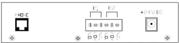
Rear View
Setup
Information specific to your application will need to be programmed into the VIP-811 using a computer. The PC used for programming should be connected to the same subnet as the VIP-811. Setup will be done using the IP Solutions Setup Tool. Download the latest version of the free IP Solutions Setup Tool from the Valcom website at www.valcom.com/vipsetuptool.
Status Indicator Lights
The VIP-811 has 3 status indication lights on the front panel:
STATUS: Flashes then illuminates to indicate power.
LINK: Indicates 100 Mbit Ethernet connection when illuminated. No activity indicates 10 Mbit connection.
ACT: Indicator flashes to indicate network activity.

Front View
TECHNICAL ASSISTANCE
When trouble is reported, verify power is being supplied to the unit and there are no broken connections. If a spare unit is available, substitute a spare unit for the suspected defective unit.
Assistance in troubleshooting is available from the factory. Call (540) 563-2000 and press 1 for Technical Support or via email at support@valcom.com.
When requesting assistance, you should include all available information. General information and troubleshooting procedures are available on the Valcom website at www.valcom.com.
Valcom equipment is not field repairable. Valcom, Inc. maintains service facilities in Roanoke, VA. Should repairs be necessary, attach a tag to the unit clearly stating your company name, address, phone number, contact person and the nature of the problem. Send the unit to:
Valcom, Inc.
Repair & Return Dept.
5614 Hollins Road
Roanoke, Va. 24019-5056
VALCOM LIMITED WARRANTY
Valcom, Inc. warrants its products only to the original purchaser, for its own use, to be free from defects in materials and workmanship under conditions of normal use and service for a period of one year from the date of shipment. This Limited Warranty obligation shall be limited to the replacement, repair or refund of any such defective device within the warranty period, provided that:
- inspection by Valcom, Inc. indicates the validity of the claim;
- the defect is not the result of damage, misuse or negligence after the original shipment;
- the product has not been altered in any way or repaired by others and that factory sealed units are unopened (a service charge plus parts and labor will be applied to units defaced or physically damaged);
- freight charges for the return of products to Valcom are prepaid;
- all units 'out of warranty' are subject to a service charge. The service charge will cover minor repairs (major repairs will be subject to additional charges for parts and labor).
This Limited Warranty is in lieu of and excludes all other warranties, expressed or implied and in no event shall Valcom, Inc. be liable for any anticipated profits, consequential damages, loss of time or other losses incurred by the buyer in connection with the purchase, operation, maintenance, installation, removal or use of the product. The maximum liability of Valcom under this warranty is limited to the purchase price of the specific Product covered by the warranty.
Disclaimer. Except for the Limited Warranty provided herein, the product is provided "as-is" without any warranty of any kind whatsoever including, without limitation, any WARRANTY OF MERCHANTABILITY, FITNESS FOR A PARTICULAR PURPOSE OR NON-INFRINGEMENT.
This warranty specifically excludes damage incurred in shipment. In the event a product is received in damaged condition, the carrier should be notified immediately. Claims for such damage should be filed with the carrier involved in accordance with the F.O.B. point.
Headquarters:
Valcom, Inc.
5614 Hollins Road Roanoke, VA 24019-5056
Phone: (540) 563-2000 FAX: (540) 362-9800

- SPECIFICATIONS
- ACCESS METHODS
- FEATURES
- DIMENSIONS/WEIGHT
- NOMINAL SPECIFICATIONS
- NOMINAL POWER REQUIREMENTS
- VIA REAR PANEL BARREL CONNECTOR
- VIA 802.3AF POE ETHERNET SWITCH
- ENVIRONMENT
- INSTALLATION
- PRECAUTIONARY DESIGNATIONS
- FCC INFORMATION
- MOUNTING
- POWER CONNECTIONS
- NETWORK CONNECTION
- SIGNAL CONNECTIONS
- SETUP
- STATUS INDICATOR LIGHTS
- TECHNICAL ASSISTANCE
- VALCOM LIMITED WARRANTY
Brand : Valcom
Model : Station Port VIP-811
Category : Network card / adapter