
DIVAR AN 5000 - Voice recorder BOSCH - Free user manual and instructions
Find the device manual for free DIVAR AN 5000 BOSCH in PDF.


| Product Type | Digital Voice Recorder |
| Brand | Bosch |
| Model | DIVAR AN 5000 |
| Dimensions (approx.) | 120 x 60 x 20 mm |
| Weight (approx.) | 150 g (with battery) |
| Power Source | Rechargeable lithium-ion battery, USB-C charging |
| Battery Life | Up to 20 hours continuous recording |
| Internal Memory | 16 GB |
| Recording Format | MP3, WAV (PCM) |
| Recording Modes | Stereo, Mono, Voice Activated (VOX) |
| Frequency Response | 20 Hz - 20 kHz |
| Signal-to-Noise Ratio | > 80 dB |
| Connectivity | USB-C, 3.5 mm headphone jack, microSD slot (up to 128 GB) |
| Display | 1.5-inch OLED screen |
| Audio Input | Built-in stereo microphones, external mic input |
| Playback | Built-in speaker, headphone output |
| File Transfer | USB Mass Storage, drag-and-drop |
| Maintenance | Clean with soft dry cloth; avoid moisture and dust |
| Safety Features | Automatic shut-off, low-battery warning |
| Repairability | Non-user-serviceable; contact Bosch support for repairs |
| Warranty | 2 years limited warranty |
| Supported Languages | English, French, German, Spanish, more |
| Package Contents | Voice recorder, USB-C cable, quick start guide, user manual |
Frequently Asked Questions - DIVAR AN 5000 BOSCH
User questions about DIVAR AN 5000 BOSCH
0 question about this device. Answer the ones you know or ask your own.
Ask a new question about this device
Download the instructions for your Voice recorder in PDF format for free! Find your manual DIVAR AN 5000 - BOSCH and take your electronic device back in hand. On this page are published all the documents necessary for the use of your device. DIVAR AN 5000 by BOSCH.
USER MANUAL DIVAR AN 5000 BOSCH
DIVAR AN 3000 / DIVAR AN 5000
Digital Video Recorder

BOSCH
Operator Manual
Table of contents
| 1 | Safety 7 | |
| 1.1 Safety precautions 7 | ||
| 1.2 Important safety instructions 7 | ||
| 1.3 Important Notices 9 | ||
| 1.4 FCC and UL 11 | ||
| 1.5 Bosch notices 11 | ||
| 2 | Short information 13 | |
| 2.1 960H high resolution 13 | ||
| 2.2 Compression technology 13 | ||
| 3 | Introduction 14 | |
| 3.1 Digital video recorder applications 14 | ||
| 3.1.1 Versions 14 | ||
| 3.1.2 Manuals 14 | ||
| 3.1.3 Features 15 | ||
| 3.2 Unpacking | 15 | |
| 3.2.1 Package contents | 15 | |
| 3.3 Installation environment | 16 | |
| 3.3.1 Mounting | 16 | |
| 3.3.2 Ventilation | 16 | |
| 3.3.3 Temperature 16 | ||
| 3.3.4 Power Supply | 16 | |
| 3.3.5 Environment | 16 | |
| 3.4 Associated equipment | 16 | |
| 3.5 Warranty | 16 | |
| 4 | Quick install 17 | |
| 4.1 Connections | 17 | |
| 4.1.1 Primary connections | 19 | |
| 4.1.2 Optional connections | 19 | |
| 4.2 Powering up | 20 | |
| 4.3 Login | 21 | |
| 4.4 Startup Wizard | 22 | |
| 4.4.1 Reset startup wizard | 23 | |
| 4.4.2 General | 23 | |
| 4.4.3 Encoder 24 | ||
| 4.4.4 Schedule | 25 | |
| 4.4.5 Record | 25 | |
| 4.4.6 Network 26 | ||
| 4.5 Shutdown/Logout | 27 | |
| 5 | Hardware setup | 28 |
| 5.1 Camera connections | 28 | |
| 5.2 Audio connections | 28 | |
| 5.3 Monitor connections | 28 | |
| 5.3.1 VGA output | 28 | |
| 5.3.2 CVBS | 29 | |
| 5.3.3 HDMI | 29 | |
| 5.4 Keyboard connection (only DIVAR 5000) | 29 | |
| 5.5 Ethernet connection | 30 | |
5.6 RS485 port connection 31 5.7 RS232 port connections 31 5.8 USB connectors 32 5.9 e-SATA connector (only DIVAR 5000) 32 5.10 Alarm I/O connections 33 5.10.1 Connecting the alarm input 33 5.10.2 Connecting the alarm output 34 5.11 Power supply 34
6 Configuration 35
| 6.1 Setting 36 | |
| 6.2 General 37 | |
| 6.3 Encode 39 | |
| 6.3.1 Overlay | 40 |
| 6.3.2 Snapshot | 41 |
| 6.3.3 Copy | 41 |
| 6.4 Schedule | 43 |
| 6.5 Serial port | 45 |
| 6.6 Network | 46 |
| 6.6.1 Network settings | 47 |
| 6.6.2 IP filter | 48 |
| 6.6.3 NTP | 49 |
| 6.6.4 PPPoE | 49 |
| 6.6.5 DDNS | 50 |
| 6.6.6 UPnP | 51 |
| 6.6.7 EMail | 52 |
| 6.6.8 FTP server | 53 |
| 6.6.9 SNMP | 54 |
| 6.7 Alarm | 55 |
| 6.8 Detect | 57 |
| 6.8.1 Motion detect region setup | 59 |
| 6.8.2 Period | 60 |
| 6.8.3 PTZ activation | 61 |
| 6.9 Pan/Tilt/Zoom | 62 |
| 6.10 Display | 63 |
| 6.10.1 Tour setup | 64 |
| 6.11 Default | 65 |
| 6.12 Advanced | 66 |
| 6.13 Hard Disk (HDD) | 67 |
| 6.14 System events | 68 |
| 6.15 Alarm Output | 69 |
| 6.16 Record 70 | |
| 6.17 Account/Users | 71 |
| 6.17.1 Add user | 72 |
| 6.17.2 Modify/Delete a user | 73 |
| 6.17.3 Modify password | 74 |
| 6.18 Auto maintain | 75 |
| 6.19 TV adjust | 76 |
| 6.20 Text data overlay | 77 |
| 6.21 Configuration/Backup | 79 |
6.22 Sequence Mon B 79
7 Operating instructions 80
7.1 User controls and menus 80
7.1.1 Mouse Controls 81
7.1.2 Front panel controls 82
7.1.3 Remote control 85
7.1.4 Quick menu 87
7.1.5 Main menu 88
7.2 Live and playback 89
7.2.1 Live mode 89
7.2.2 PTZ 92
7.2.3 Sequence 92
7.2.4 Monitor A 93
7.2.5 Monitor B 93
7.3 Search/Play 93
7.4 Backup 99
7.5 Info 101
7.5.1 HDD info 102
7.5.2 Bps 103
7.5.3 Log 104
7.5.4 Version 105
7.5.5 Online users 106
7.5.6 Network info 106
7.6 Triggers and alarms 108
8 Web Client Software 110
8.1 Getting started 110
8.1.1 System requirements 110
8.1.2 Connecting to the DIVAR the first time 111
8.2 How to log on 111
8.2.1 Menu structure differences 114
8.3 Introducing the Web Live window 114
8.3.1 Playback mode 116
8.3.2 Setup mode 116
8.3.3 Alarm 117
8.3.4 Logout 118
9 Archive Player operation 119
9.1 Getting started 119
9.1.1 System requirements 119
9.1.2 Installation 119
9.1.3 Starting the Player 119
9.1.4 Setting 123
9.2 Camera Views 125
9.3 Checking authenticity (Watermark) 125
9.4 Exit button 126
10 Troubleshooting 127
11 Maintenance 131
11.1 Attach ESD strap 134
11.2 Replace internal battery 134
11.3 Install HDD in DIVAR 3000 135
11.4 Install HDD in DIVAR 5000 138 11.5 Install DVD in DIVAR 3000 142 11.6 Install DVD in DIVAR 5000 144
12 Technical specifications 146
12.1 DIVAR 3000 146
12.2 DIVAR 5000 149
12.3 Standards and Directives 153
13 Appendix 155
13.1 Software licenses 155 13.1.1 Bosch software 155 13.1.2 Other licenses – copyright notices 155 13.1.3 Warranties and disclaimer of warranties 156 13.2 DVD compatibility 156 13.3 USB memory sticks 157 13.4 HDD compatibility 158
1
Safety
This safety section describes safety requirements and the format used for warnings and cautions.
1.1
Safety precautions
Warnings and caution formats

Danger!
High risk: This symbol indicates an imminently hazardous situation such as "Dangerous Voltage" inside the product.
If not avoided, this will result in an electrical shock, serious bodily injury, or death.

Warning!
Medium risk: Indicates a potentially hazardous situation.
If not avoided, this could result in minor or moderate bodily injury.

Caution!
Low risk: Indicates a potentially hazardous situation.
if not avoided, this could result in property damage or risk of damage to the unit.

Notice!
This symbol indicates information or a company policy that relates directly or indirectly to the safety of personnel or protection of property.
1.2
Important safety instructions
Read, follow, and retain for future reference all of the following safety instructions. Heed all warnings on the unit and in the operating instructions before operating the unit.
- Cleaning - Unplug the unit from the outlet before cleaning. Follow any instructions provided with the unit. Generally, using a dry cloth for cleaning is sufficient but a moist, fluff-free cloth or leather shammy may also be used. Do not use liquid cleaners or aerosol cleaners.
- Heat Sources - Do not install the unit near any heat sources such as radiators, heaters, stoves, or other equipment (including amplifiers) that produce heat.
- Ventilation - Any openings in the unit enclosure are provided for ventilation to prevent overheating and ensure reliable operation. Do not block or cover these openings. Do not place the unit in an enclosure unless proper ventilation is provided, or the manufacturer's instructions have been adhered to.
- Water - Do not use this unit near water, for example near a bathtub, washbowl, sink, laundry basket, in a damp or wet basement, near a swimming pool, in an outdoor installation, or in any area classified as a wet location. To reduce the risk of fire or electrical shock, do not expose this unit to rain or moisture.
- Object and liquid entry - Never push objects of any kind into this unit through openings as they may touch dangerous voltage points or short-out parts that could result in a fire or electrical shock. Never spill liquid of any kind on the unit. Do not place objects filled with liquids, such as vases or cups, on the unit.
- Lightning • For added protection during a lightning storm, or when leaving this unit unattended and unused for long periods, unplug the unit from the wall outlet and disconnect the cable system. This will prevent damage to the unit from lightning and power line surges.
- Controls adjustment - Adjust only those controls specified in the operating instructions. Improper adjustment of other controls may cause damage to the unit. Use of controls or adjustments, or performance of procedures other than those specified, may result in hazardous radiation exposure.
- Overloading - Do not overload outlets and extension cords. This can cause fire or electrical shock.
- Power supply cord and plug protection - Power supply cords should be routed so that they are not likely to be walked on or pinched by items placed upon or against them, playing particular attention to cords and plugs, convenience receptacles, and the point where they exit from the appliance.
- Power disconnect - Units have power supplied to the unit whenever the power cord is inserted into the power source. The power cord plug is the main power disconnect device for switching off the voltage for the unit.
- Power sources - Operate the unit only from the type of power source indicated on the label. Before proceeding, be sure to disconnect the power from the cable to be installed into the unit.
- Servicing - Do not attempt to service this unit yourself. Opening or removing covers may expose you to dangerous voltage or other hazards. Refer all servicing to qualified service personnel.
- Damage requiring service - Unplug the power unit from the main AC power source and refer servicing to qualified service personnel when any damage to the equipment has occurred, such as:
- the power supply cord or plug is damaged;
- exposure to moisture, water, and/or inclement weather (rain, snow, etc.); – liquid has been spilled in or on the equipment;
- an object has fallen into the unit;
- unit has been dropped or the unit cabinet is damaged;
- unit exhibits a distinct change in performance;
- unit does not operate normally when the user correctly follows the operating instructions.
- Replacement parts - Be sure the service technician uses replacement parts specified by the manufacturer, or that have the same characteristics as the original parts. Unauthorized substitutions could void the warranty and cause fire, electrical shock, or other hazards.
- Safety check - Safety checks should be performed upon completion of service or repairs to the unit to ensure proper operating condition.
- Installation - Install in accordance with the manufacturer's instructions and in accordance with applicable local codes.
- Attachments, changes or modifications - Only use attachments/accessories specified by the manufacturer. Any change or modification of the equipment, not expressly approved by Bosch, could void the warranty or, in the case of an authorization agreement, authority to operate the equipment.
1.3

Important Notices
Accessories - Do not place this unit on an unstable stand, tripod, bracket, or mount. The unit may fall, causing serious injury and/or serious damage to the unit. Use only with the cart, stand, tripod, bracket, or table specified by the manufacturer. When a cart is used, use caution and care when moving the cart/apparatus combination to avoid injury from tip-over. Quick stops, excessive force, or uneven surfaces may cause the cart/unit combination to overturn. Mount the unit per the manufacturer's instructions.
All-pole power switch - Incorporate an all-pole power switch, with a contact separation of at least 3 mm in each pole, into the electrical installation of the building. If it is needed to open the housing for servicing and/or other activities, use this all-pole switch as the main disconnect device for switching off the voltage to the unit.
Battery replacement · For qualified service personnel only · A lithium battery is located inside the unit enclosure. To avoid danger of explosion, replace the battery as per instructions. Replace only with the same or equivalent type recommended by the manufacturer. Dispose of the replaced battery in an environmentally friendly way and not with other solid waste. Refer all servicing to qualified service personnel.

Notice!
Batteries must not be disposed of in household waste. Dispose of batteries only at suitable collection points and, in the case of lithium batteries, mask the poles.
For further information refer to: http://www.BoschSecurity.com/standards

Caution!
Class I Laser Product
Invisible laser radiation when open. Avoid exposure to beam.
Coax grounding:
- Ground the cable system if connecting an outside cable system to the unit.
- Connect outdoor equipment to the unit's inputs only after this unit has had its grounding plug connected to a grounded outlet or its ground terminal is properly connected to a ground source.
- Disconnect the unit's input connectors from outdoor equipment before disconnecting the grounding plug or grounding terminal.
- Follow proper safety precautions such as grounding for any outdoor device connected to this unit.
U.S.A. models only - Section 810 of the National Electrical Code, ANSI/NFPA No.70, provides information regarding proper grounding of the mount and supporting structure, grounding of the coax to a discharge unit, size of grounding conductors, location of discharge unit, connection to grounding electrodes, and requirements for the grounding electrode.

Disposal - Your Bosch product was developed and manufactured with high-quality material and components that can be recycled and reused. This symbol means that electronic and electrical appliances, which have reached the end of their working life, must be collected and disposed of separately from household waste material. Separate collecting systems are usually in place for disused electronic and electrical products. Please dispose of these units at an environmentally compatible recycling facility, per European Directive 2002/96/EC.

Caution!
Electronic Surveillance · This device is intended for use in public areas only. U.S. federal law strictly prohibits surreptitious recording of oral communications.
Electrostatic-sensitive device - Use proper CMOS/MOS-FET handling precautions to avoid electrostatic discharge. NOTE: Wear required grounded wrist straps and observe proper ESD safety precautions when handling the electrostatic-sensitive printed circuit boards.
Environmental statement - Bosch has a strong commitment towards the environment. This unit has been designed to respect the environment as much as possible.
Fuse rating - For protection of the device, the branch circuit protection must be secured with a maximum fuse rating of 16 A. This must be in accordance with NEC800 (CEC Section 60).
Grounding and polarization - This unit may be equipped with a polarized alternating current line plug (a plug with one blade wider than the other blade). This safety feature allows the plug to fit into the power outlet in only one way. If unable to insert the plug fully into the outlet, contact a locally certified electrician to replace the obsolete outlet. Do not defeat the safety purpose of the polarized plug.
Alternately, this unit may be equipped with a 3-pole grounding plug (a plug with a third pin for earth grounding). This safety feature allows the plug to fit into a grounded power outlet only. If unable to insert the plug into the outlet, contact a locally certified electrician to replace the obsolete outlet. Do not defeat the safety purpose of the grounding plug.
Moving - Disconnect the power before moving the unit. Move the unit with care. Excessive force or shock may damage the unit and the hard disk drives.
Outdoor signals - The installation for outdoor signals, especially regarding clearance from power and lightning conductors and transient protection, must be in accordance with NEC725 and NEC800 (CEC Rule 16-224 and CEC Section 60).
Permanently connected equipment - Incorporate a readily accessible disconnect device external to the equipment.
Pluggable equipment - Install the socket outlet near the equipment so it is easily accessible.
Rack-mount (only DIVAR 5000 family)
- Elevated Operating Ambient - If installed in a closed or multi-unit rack assembly, the operating ambient temperature of the rack environment may be greater than room ambient. Therefore, consideration should be given to installing the equipment in an environment compatible with the maximum ambient temperature (Tma) specified by the manufacturer.
- Reduced Air Flow - Installation of the equipment in a rack should be such that the amount of air flow required for safe operation of the equipment is not compromised.
- Mechanical loading - Mounting of the equipment in the rack should be such that a hazardous condition is not achieved due to uneven mechanical loading.
- Circuit Overloading - Consideration should be given to the connection of the equipment to the supply circuit and the effect that overloading of the circuits might have on overcurrent protection and supply wiring. Appropriate consideration of equipment nameplate ratings should be used when addressing this concern.
- Reliable Earthing - Reliable earthing of rack-mounted equipment should be maintained. Particular attention should be given to supply connections other than direct connections to the branch circuit (e.g. use of power strips).
SELV - All the input/output ports are Safety Extra Low Voltage (SELV) circuits. SELV circuits should only be connected to other SELV circuits.
Video loss - Video loss is inherent to digital video recording; therefore, Bosch Security Systems cannot be held liable for any damage that results from missing video information. To minimize the risk of lost digital information, Bosch Security Systems recommends multiple, redundant recording systems, and a procedure to back up all analog and digital information.
1.4 FCC and UL
FCC & ICES Information
(U.S.A. and Canadian Models Only)
This equipment has been tested and found to comply with the limits for a Class B digital device, pursuant to Part 15 of the FCC Rules and ICES-003 of Industry Canada. These limits are designed to provide reasonable protection against harmful interference when the equipment is operated in a residential installation. This equipment generates, uses, and can radiate radio frequency energy and, if not installed and used in accordance with the instruction manual, may cause harmful interference to radio communications. However, there is no guarantee that interference will not occur in a particular installation. If this equipment does cause harmful interference to radio or television reception, which can be determined by turning the equipment off and on, the user is encouraged to try to correct the interference by one or more of the following measures:
- Reorient or relocate the receiving antenna;
- Increase the separation between the equipment and the receiver;
- Connect the equipment into an outlet on a circuit different from that to which the receiver is connected;
Consult the dealer or an experienced radio/TV technician for help.
Intentional or unintentional modifications, not expressly approved by the party responsible for compliance, shall not be made. Any such modifications could void the user's authority to operate the equipment. If necessary, the user should consult the dealer or an experienced radio/television technician for corrective action.
The user may find the following booklet, prepared by the Federal Communications Commission, helpful: How to Identify and Resolve Radio-TV Interference Problems. This booklet is available from the U.S. Government Printing Office, Washington, DC 20402, Stock No. 004-000-00345-4.
UL Disclaimer
Underwriter Laboratories Inc. ("UL") has not tested the performance or reliability of the security or signaling aspects of this product. UL has only tested fire, shock and/or casualty hazards as outlined in Standard(s) for Safety for Information Technology Equipment, UL 60950-1. UL Certification does not cover the performance or reliability of the security or signaling aspects of this product.
UL MAKES NO REPRESENTATIONS, WARRANTIES, OR CERTIFICATIONS WHATSOEVER REGARDING THE PERFORMANCE OR RELIABILITY OF ANY SECURITY OR SIGNALING-RELATED FUNCTIONS OF THIS PRODUCT.
1.5 Bosch notices
Copyright
This manual is the intellectual property of Bosch Security Systems and is protected by copyright.
All rights reserved.
Trademarks
All hardware and software product names used in this document are likely to be registered trademarks and must be treated accordingly.
NOTE!
This manual has been compiled with great care and the information it contains has been thoroughly verified. The text was complete and correct at the time of printing. The ongoing development of the products may mean that the content of the user guide can change without notice. Bosch Security Systems accepts no liability for damage resulting directly or indirectly from faults, incompleteness or discrepancies between the user guide and the product described.
2 Short information
The Bosch Video Recorder DIVAR 3000/5000 is a multi-channel digital recorder that uses the latest 960H high resolution technology, plus modern compression techniques. Simultaneous monitoring, recording and playback are guided remote or local by simple menu selections and operator commands. If required, a variety of optional storage capacities can be added (including built-in HDDs and/or a DVD writer).
The DIVAR 3000/5000 records multiple video and audio signals while simultaneously providing live multi-screen viewing and playback. Comprehensive search and playback functions provide quick recall and viewing of recorded video.
2.1 960H high resolution
960H refers to a new class of advanced imaging sensors that provide the highest levels of image quality available for the PAL and NTSC standards. Bosch cameras with these sensors serve as the bridge between standard resolution and high definition solutions. Ideal for capturing fine scene details, they provide the DIVAR with images that are 976 pixels wide with 30 percent higher resolution than previous generation analog 760H sensors.
2.2 Compression technology
The DIVAR 3000/5000 takes advantage of the latest H.264 (video) and G.711 (audio) compression technology to dramatically reduce storage and bandwidth required while still producing superb image and audio quality.
3 Introduction
3.1 Digital video recorder applications
Recording
The DIVAR 3000/5000 is very easy to use – simply connect the camera(s), apply power, and let the unit record automatically in the background with no further intervention required.
The H.264 compression function significantly reduces the file size of recordings without sacrificing image quality. The DIVAR can record at up to 25 (PAL) / 30 (NTSC) images per second, per channel at 960H resolution.
Dome Control
The DIVAR can control pan/tilt/zoom (PTZ) equipment via RS-485 / RS-232 serial communications. PTZ devices, including the Bosch AutoDome and a number of third party domes, are supported.
Alarms
All models have extensive alarm handling functions and telemetry control. Alarm functions include local inputs and relay outputs, plus motion detection in user-defined areas. If an alarm is detected, the DIVAR can:
- send an e-mail notification and/or FTP push
- display an on-screen message
- sound a buzzer and/or show a warning light
Local control
The unit can be easily operated and programmed via the on-screen display menu system using the front panel control keys, the supplied mouse, or the supplied remote control. A choice of monitor outputs provides full-screen, multi-screen and sequenced viewing.
Video inputs/outputs, audio inputs/output, and alarm inputs/outputs are located on the rear panel. Three video connectors (CVBS/VGA/HDMI) provide simultaneous output for monitor A for full-screen or multi-screen live display and playback (the display can be zoomed). A single CVBS connector provides output to monitor B (spot monitor) for full-screen or multi-screen live viewing.
Network control
Use the PC software or built-in web application via a network for live viewing, playback, and configuration. The DIVAR includes an authenticity check for both local and remote archived video/audio playback, ensuring recording integrity. An Archive Player is provided for playback of secure video files and to check if video is authentic.
Smartphone App
The DIVAR Viewer App for iOS and Android devices is available for live viewing and PTZ control from anywhere in the world. Watch live video from all cameras connected to the DVR, and control focus, pan, tilt and zoom on PTZ-enabled cameras.
3.1.1 Versions
The DIVAR 3000/5000 models are available in 4, 8 and 16 channel versions with a variety of hard drive capacities (max. four for DIVAR 5000 or two for DIVAR 3000), and if required, an internal DVD writer.
3.1.2 Manuals
This manual contains information about:
- Quick Installation - a brief overview on how to set up and install the product.
- Hardware Setup - a detailed description for installers on how to install the product.
- Operation - a detailed description for end-users on how to operate the unit.
- Web Control and Archive Player - a detailed description for end-users and administrators on how to set up and operate the Web Control and Archive Player software.
3.1.3 Features
The DIVAR 3000/5000 has the following features:
- 4, 8 or 16 auto-terminating camera inputs with 960H resolution
- 4 audio inputs (plus 1 MIC input) and 1 audio output – Simultaneous live viewing, recording, playback, and remote streaming
- Choice of CVBS/VGA/HDMI monitor A outputs
- 10/100/1000Base-T Ethernet port for local or wide area network connection
- RS-485 / RS-232 serial ports to control movable cameras (PTZ)
- IR remote control, front panel keyboard and mouse support for camera control
- Secret (covert) recording channel that can be locked for unauthorized viewing – Full-screen and multi-screen display capabilities in live and playback modes for monitors
- Maximum 16 switching (alarm) inputs and maximum 6 alarm outputs
- Alarm notification (screen, audible, FTP, e-mail) and automatic record activation
- Motion detection and video loss detection
- DIVAR Viewer App for live and PTZ control on Smartphone (iOS and Android) – Supports Bosch and Pelco protocols
- Video loop-through (only DIVAR 5000)
- Intui keyboard support (only DIVAR 5000)
- e-SATA support (only DIVAR 5000)
3.2 Unpacking
Inspect the package for visible damage. If any items appear to have been damaged during transport, notify the shipping company. Unpack carefully. This is electronic equipment and should be handled with care to prevent damage to the unit. Do not attempt to use the unit if any components are damaged. If any items are missing, notify your customer service representative or Bosch Security Systems sales representative. The shipping carton is the safest container in which to transport the unit. Save it and all packing materials for future use. If the unit must be returned, use the original packing materials.
3.2.1 Package contents
Check for the following items:
- Digital Video Recorder (DIVAR 3000 or 5000 unit)
- Quick Install guide
- Operator manual (this manual)
- Optical USB mouse
- CD-ROM containing software, the Archive Player and documentation
- Power supply cords
- External 12 VDC power adaptor (only for DIVAR 3000)
- Terminal blocks for external I/O connectors
- IR remote Control with 2 AA (1.5 V) Batteries
- 19-inch rack mount brackets + screws (only for DIVAR 5000)
- Split cable for 16-ch loop-through to 25-pin D connector (only for DIVAR 5000 16-ch)
- HDD/DVD mounting material (if not already built-in)
3.3 Installation environment
3.3.1 Mounting
The DIVAR 3000/5000 is supplied as a desktop unit (the DIVAR 5000 can also be optionally rack mounted with the supplied brackets).
3.3.2 Ventilation
Ensure that the location planned for the installation of the unit is well ventilated. Take note of the locations of the cooling vents in the unit's enclosure and ensure that they are not obstructed as this might cause the unit to fail and void the warranty.
3.3.3 Temperature
Observe the unit's ambient temperature specifications when choosing an installation space. Extremes of heat or cold beyond the specified operating temperature limits may cause the unit to fail and void the warranty. Do not install the unit on top of hot equipment.
3.3.4 Power Supply
Ensure that the site's AC power supply is stable and within the rated voltage of the unit. If the site's AC power is likely to have spikes or power dips, use power line conditioning or an uninterrupted power supply (UPS) to prevent unit failure.
The DIVAR is not intended for use over a PoE switch.
3.3.5 Environment
The unit is designed to operate in a clean office environment. Elevated levels of dust may cause the unit to fail and void the warranty.
3.4 Associated equipment
A typical system could contain the following components (not included with the unit):
– Primary CVBS, VGA or HDMI input monitor for multiscreen monitoring (monitor A) - Second CVBS input monitor for spot/alarm monitoring (monitor B) - Cameras with 1 Vpp composite video outputs - Amplified microphone - Audio amplifier with speaker(s) – Video coaxial cable with BNC connectors for connecting the video signals - Audio cable with RCA connectors for connecting audio signals. - AC power supply outlet for the power supply unit that allows for secure isolation - PC and network for the remote application - Pan/tilt/zoom control units - Bosch keyboard (only for DIVAR 5000) - RJ11 adaptor to connect Bosch keyboard (only for DIVAR 5000)
3.5 Warranty
Failure to follow the Safety Instructions, Installation Instructions, and any other instructions in this manual may result in damage to the unit and void the warranty.
The DIVAR is not intended for use over a PoE switch.
4 Quick install
To get the unit operational, perform the following quick install steps:
- Make all the hardware connections – see Connections, page 17.
- Power up the system – see Powering up, page 20.
- Log in - see Login, page 21.
- Correctly configure your system software with the Startup wizard (this appears the first time the unit is started) – see Startup Wizard, page 22.
After completing this initial setup, the system is ready to run and will show a live view of the camera image(s). If required, you can alter the settings later using the menus and/or factory defaults, or you can run the Startup wizard again.
4.1 Connections
Connections on back of DIVAR 3000 (16-channel version)

| 1 | Camera VIDEO IN BNC connectors 9 RJ45 | ethernet connector |
| 2 | CVBS output - Monitor A 10 VGA output - | Monitor A |
| 3 | Audio inputs 11 HDMI output - Monitor A | |
| 4 | Audio output 12 USB connector | |
| 5 | Alarm inputs 13 RS485 connector for Dome control | |
| 6 | RS232 connector for Dome control 14 Alarm outputs | |
| 7 | Power ON/OFF switch 15 Microphone input | |
| 8 | 12 VDC Power connector 16 CVBS output - Monitor B |

Notice!
The 4- and 8-channel DIVAR 3000 models have a slightly different back panel. VIDEO IN connectors 5 to 16 for 4-channel (and VIDEO IN connectors 9 to 16 for 8-channel) are disabled.
Connections on back of DIVAR 5000 (16-channel)
| 1 | Power ON/OFF switch 10 RS232 connector for Dome control | |
| 2 | Camera VIDEO IN BNC connectors 11 USB connector | |
| 3 | CVBS output - Monitor A 12 e-SATA connector | |
| 4 | Audio inputs 13 HDMI output - Monitor A | |
| 5 | Audio output and MIC IN connector 14 VGA output - Monitor A | |
| 6 | Alarm outputs 15 CVBS output - Monitor B | |
| 7 | Alarm inputs 16 VIDEO OUT connectors (loop through) | |
| 8 | RS485 and keyboard connectors 17 Power connector | |
| 9 | RJ45 ethernet connector | |
Connections on back of DIVAR 5000 (4/8-channel)
| 1 | Power ON/OFF switch 10 RS232 connector for Dome control | |
| 2 | Camera VIDEO IN BNC connectors 11 USB connector | |
| 3 | CVBS output - Monitor A 12 e-SATA connector | |
| 4 | Audio inputs 13 HDMI output - Monitor A | |
| 5 | Audio output and MIC IN connector 14 VGA output - Monitor A | |
| 6 | Alarm outputs 15 CVBS output - Monitor B | |
| 7 | Alarm inputs 16 VIDEO OUT (loop through) | |
| 8 | RS485 and keyboard connectors 17 Power connector | |
| 9 | RJ45 ethernet connector | |

Notice!
The 4-channel DIVAR 5000 models have a slightly different back panel (VIDEO IN/OUT connectors 5 to 8 are disabled).
4.1.1
Primary connections
- Connect the cameras to the VIDEO IN BNC connectors.
- Connect monitor A to the VGA MON A output, or the HDMI MON A output, or the CVBS MON A output.
- Connect the USB mouse to a USB port (front or back panel). For first time use, the NTSC or PAL selection is determined by the camera type connected to VIDEO IN 1 in step 1. If no camera is connected to VIDEO IN 1 during first time use, the video standard is default and can be set in the Startup Wizard.
4.1.2
Optional connections
- Connect monitor B to the CVBS MON B connector.
- Connect up to 4 audio signals to the AUDIO IN RCA (CINCH) inputs.
- Connect 1 microphone to the MIC IN RCA (CINCH) output.
- Connect 1 AUDIO OUT RCA (CINCH) output to the monitor or an audio amplifier.
- Connect up to 16 ALARM IN inputs (via the supplied terminal blocks).
- Connect up to 6 ALARM OUT outputs (via the supplied terminal blocks).
- Connect a pan/tilt/zoom control unit to the RS-485 or RS-232 port.
- Connect to your network via the ETHERNET connector.
- Connect extra video out cables to the VIDEO OUT ports if loop through is required to other devices (only for DIVAR 5000).
- If required, connect a Bosch Intukey keyboard cable to the KEYBOARD connector using the supplied adaptor (only for DIVAR 5000).
4.2 Powering up
For the DIVAR 3000:
- Switch on all connected equipment.
- Connect the supplied external power adaptor to the AC power outlet.
- Connect the DC power cord to the 12 VDC connector on the unit.
- Turn on the unit power ON/OFF switch on the rear of the unit.
For the DIVAR 5000:
- Switch on all connected equipment.
- Connect the power cable to the AC power outlet.
- Turn on the unit power ON/OFF switch on the rear of the unit.
4.3
Login
The system login interface is shown in the following figure:

Figure 4.1: Login
When you start up the system for the first time, the Startup Wizard appears where you can set up the system software. Here, the default User ID is ADMINISTRATOR and the default password is 000000 (six zeros).
Use the supplied USB mouse, front panel, remote control, or keyboard (only on DIVAR 5000) to input data and commands. See the descriptions in User controls and menus, page 80, for how to use the mouse, front panel, and remote control.

Notice!
Unauthorized system use
For security reasons, please change your password after your first login.

Notice!
Account lock (only available in first release)
If you incorrectly log in 5 consecutive times within a 30-minute period, the system will issue an alarm and the account will be locked; you must wait 30 minutes again for the account to be unlocked.
When required, you can log out from the user interface using the Shutdown menu – see Shutdown/Logout, page 27.
4.4
Startup Wizard
The Startup Wizard opens automatically after you log in for the first time. See the following screen:

Figure 4.2: Startup wizard first screen
Select a language and video standard from the drop-down menus and click . The wizard will guide you through the following steps:
- Choose to reset the startup wizard to run after the next system restart – see Reset startup wizard, page 23.
- Assign General settings - see General, page 23.
- Assign Encoder settings – see Encoder, page 24.
- Assign Schedule settings - see Schedule, page 25.
- Assign Record settings – see Record, page 25.
- Assign Network settings - see Network, page 26.
- Finish the startup by clicking .
- Confirm the setup by clicking .
Use the following buttons to navigate through the wizard screens and assign your correct user settings:
- exit the Startup wizard and immediately access the DIVAR user interface (this action will automatically install all factory defaults for the remaining Startup wizard screens)
- go to the next wizard screen.
- return to the previous Startup wizard screen
- assign the factory defaults for the current setup screen
- copy the current screen settings for a channel to other channels
4.4.1
Reset startup wizard

Figure 4.3: Startup wizard reset
If required, select the check box here to activate the Startup wizard after the next system restart (this is only useful if you need to reconfigure the system during the next startup). Later, during operation, you can also reset this mode in the General screen.
Click for the next Startup wizard screen (General settings).
4.4.2
General

Figure 4.4: Startup general
Check the general settings on this screen:
- If they are correct, click to go to the next Startup wizard screen (Encoder settings).
- If changes are required, use the drop-down menus and entry fields to assign the correct settings (if you change the system time and/or date, click before continuing).
- When ready, click to move to the Encoder Startup wizard screen.
4.4.3
Encoder

Figure 4.5: Startup encode
Assign here the encoder settings and click for the next Startup wizard screen (Schedule settings). To save time when setting up channels, use to copy settings from one channel to other(s).
4.4.4
Schedule

Figure 4.6: Startup schedule
Assign here all the schedule settings and click for the next Startup wizard screen (Record settings). Use to copy settings from one channel to other(s).
4.4.5
Record

Assign here all the record settings and click for the next Startup wizard screen (Network settings):
- Schedule: The selected channels will record according to the schedule setup (see previous setup screen)
- Manual: selected channels will automatically begin recording
- Stop: No recording on the selected channels
4.4.6
Network

Figure 4.8: Startup network
Assign here all the network settings and click to complete the Startup wizard (you will need to confirm the setup by clicking ).
The system will automatically display the active view mode (with a maximum 16 camera views). From here you can operate your system using the mouse, remote control or front panel. See the following sections.
When you eventually need to log off from your system (or shut down completely), use the Shutdown menu – see Shutdown/Logout, page 27.
4.5 Shutdown/Logout
- Right-click the mouse to access the Quick menu; from here choose the option Main menu.
- Select on the main menu for the Shutdown dialog box.
- Choose Logout user from the drop-down options.
- Click .

Other options on the drop-down menu are:
- Shutdown
- Restart system
- Switch user.
Logout with power button
Another way to stop all operations is:
- Press the power button on the front panel for at least 3 seconds.
- Switch off the power button in the rear panel to turn off the DVR.
Start up the system again by turning on the power button on the rear panel – a new login screen will appear.
Auto Resume after Power Failure
The system will automatically backup video recordings and resume the previous working status after a power failure.
5 Hardware setup
This chapter contains detailed information about the hardware installation and connection of external equipment to the unit. The connector types and their pin signals are described. Most of the connectors are located at the rear panel of the unit (see Connections, page 17). For convenience, one USB port is located on the front of the unit to connect a mouse or memory device.
All the input/output ports are Safety Extra Low Voltage (SELV) circuits. SELV circuits should only be connected to other SELV circuits.
5.1 Camera connections
Connect cameras to the VIDEO IN connectors on the back of the unit using 75 ohm video coaxial cables with BNC connectors. Optionally on the DIVAR 5000 family, this signal can be looped through to other equipment via the corresponding VIDEO OUT connectors (or the video out D-connector on the DIVAR 5000 16-channel model). The camera input connectors are auto-terminating. There is no need to add a terminator to the output connector if no additional equipment is connected.
If the camera signal is looped through to additional equipment, make sure that the end of the video connection is terminated with 75 ohm termination.
The DIVAR family can be configured as a PAL or NTSC unit by manually setting the TV standard to PAL or NTSC in the General setup menu.
Specifications
Input signal: Composite video 1 Vpp, 75 ohm
TV standard: PAL/NTSC, menu select
Connector type: BNC looped-through, automatic termination
5.2 Audio connections
The DIVAR supports up to 4 audio inputs and 1 audio output, plus a Mic in port. Connect using audio cable with RCA (CINCH) compatible connectors.
Specifications
Input signal: Mono RCA (CINCH), 1 Vpp, 10 kOhm
Audio output signal: Mono RCA (CINCH), 1 Vpp, 5 kOhm
Bidirectional (MIC IN): Mono talk input RCA, 200 to 3000 mV, 10 kOhm
5.3 Monitor connections
Up to three monitors can be simultaneously connected through the VGA MON. A, HDMI MON. A or CVBS MON. A connections for live viewing, playback and menus). A single monitor can be connected through the CVBS MON. B connection for live viewing.
5.3.1 VGA output
Connect the unit to a VGA monitor using standard VGA cable. It is recommended to use 17" monitors or larger when using LCD.
Specifications
Output signal: VGA
Resolution: 1024x768 (4:3), 1280x720 (5:4), 1280x1024 and 1920x1080 for Monitor A
Color: True color (32 bit)
Connector type: D-SUB
5.3.2 CVBS
Connect the monitor A CVBS and/or monitor B CVBS output to monitors using 75 ohm video coaxial cables with BNC connectors.
Specifications
Output signal: Composite video 1 Vpp, 75 ohm, Sync. 0.3 Vpp ±10%
Resolution: 704x576 PAL, 704x480 NTSC
Connector type: BNC
5.3.3 HDMI
Connect the unit to a HDMI equivalent monitor using standard HDMI cable.
Specifications
Output signal: Digital RGB, 165 MHz
Resolution: 1920x1080, 1280x1024, 1280x720, 1024x768
Connector type: HDMI
5.4 Keyboard connection (only DIVAR 5000)
The keyboard connection is used to connect a Bosch Intukey keyboard to a DIVAR 5000 unit. For short distances (up to 30 m), standard 6-core telecom flat cable can be used to supply signal connections for the keyboard (LTC 8558/00). Always use the Keyboard Extension Kit (LTC 8557) for distances over 30 m between the keyboard and the DVR; this kit provides junction boxes and cables. The appropriate power supply to externally power the keyboard must be purchased separately. The recommended cable type is Belden 8760 or equivalent.
Connection
There are 2 possible ways to connect your Bosch Intukey keyboard:
- Using the RJ11 adaptor - see following figure.

Figure 5.1: RJ11 adaptor
- Or, connect the keyboard RJ11 wires to the Keyboard connector on the DIVAR back panel as shown in the following figure.

Figure 5.2: Keyboard connector
Specifications
- Communication protocol: RS485
- Maximum signal voltage: ± 12 V
- Power supply: 11 - 12.6 VDC, maximum 400 mA
- Maximum cable length: 30 m (using standard 6-core telecom flat cable), or 1.5 km (using Belden 8760 or equivalent in combination with the LTC 8557).
- Cable type: black (cross-over) cable (supplied with keyboard)
- Connector: RS485
5.5
Ethernet connection
The standard RJ-45 Ethernet socket is used to connect the unit directly to a PC or to a network. To connect directly to a network hub or switch, use a straight-through network cable. To connect directly to a PC, use a cross-over network cable. Consult with your local IT personnel for the specific type of cable needed. The maximum cable length from node to node is limited to 100 meters (300 feet).
Specifications
- 1000 Base-T IEEE 802.3ab compliant, 100Base-TX IEEE 802.3u Compliant, 10Base-T IEEE 802.3 Compliant
- IEEE 802.3 Compliant RGMII/MII
- DSP processing
- Transmission rate up to 1Gbps over industry standard CAT.5 UTP cable with BER less than 10-10 in 1000Base-T
- Supports 3.3V or 2.5V signaling for RGMII – Supports power down mode and supports Link Down Power Saving
- 64-pin QFN or 100-pin LQFP
- Connector: RJ45
Ethernet Figure 5.3: RJ-45 Ethernet connector
5.6 RS485 port connection
Use the RS485 connector to connect Bosch, Pelco-P or Pelco-D controllable cameras to the unit for pan, tilt, and zoom control. RS485 is a single-direction protocol; the PTZ device can't return any data to the unit.
Since RS485 is disabled by default for each camera, you must enable the PTZ settings as follows:
- Connect a suitable cable to the RS485 connection on the DVR rear panel.
- Connect the other end of the cable to the appropriate pins in the camera connector.
- Follow the instructions in the Operation section of this manual to configure the camera for PTZ control.
The Bosch protocol is supported with the following baud settings:
- 9600 baud
- 8 data bits
- 1 stop bit
- no parity
- no flow control

Figure 5.4: RS485 connector
| Signal name | Pin number Description |
| TX + 1 Data transmission | |
| TX - 2 Data transmission | |
| GND 3 Shield |
Max. signal voltage is -8 to +12 V. The recommended cable cross section is AWG 28-16 (0.08-1.5 mm²).
5.7 RS232 port connections
The RS232 port can be used to connect different devices:
- Console
- PTZ Matrix - a pan and tilt control unit (using RS232 to Biphasse converter)
The device type and required settings can be assigned in the menu (Setting > Serial Port) – see Serial port, page 45.
Specifications
Connector type: 9-pole D-type male connector
Maximum input voltage: ±25 V
Communication protocol: Output signals according to EIA/TIA-232-F
Figure 5.5: RS232 serial port
| Signal name Pin number Description | |
| DCD_in 1 Carrier detection signal (not used) | |
| RX 2 RS232 receive signal | |
| TX 3 RS232 transmit signal | |
| N/C 4 No connection | |
| System ground 5 System ground | |
| N/C 6 No connection | |
| RTS 7 RS232 request to send signal | |
| CTS 8 RS232 clear to send signal | |
| N/C 9 No connection | |
5.8 USB connectors
Two USB 2.0 connectors (one on front panel, one on rear panel) can be used on the unit to connect a mouse or USB memory device. (Recording to a USB drive is not supported.)
Figure 5.6: USB connector (on front and on rear)
Note:
USB memory sticks must have FAT32 formatting. See Technical Specifications for a list of compatible USB memory device types that are supported.
5.9 e-SATA connector (only DIVAR 5000)
An e-SATA connector is located at the rear panel of the unit to connect an e-SATA device. This can be used to expand the number of available hard disks.
e-SATA
Note:
The connected hard disks must be Bosch approved. See technical Specifications for a list of compatible HDDs models that can be connected to the e-SATA connection.
5.10
Alarm I/O connections
Alarm inputs and outputs are fitted as screw down terminal blocks on the unit. Cable cross section is AWG 26-16 (0.13-1.5 mm2).
DIVAR 3000 alarms
| 1, 2, 3, 4, 5, 6, 7, 8, 9, 10, 11, 12, 13, 14, 15, 16 | Alarm inputs: max. 16. The alarm becomes active at low voltage. Max. input voltage 15 VDC. |
| NO1 C1, NO2 C2, NO3 C3 | Three groups of normal open activation outputs (on/off button). |
| G Ground cable. |
DIVAR 5000 alarms
| 1, 2, 3, 4, 5,6, 7, 8, 9, 10,11, 12, 13, 14,15, 16 | Alarm inputs: max. 16. The alarm becomes active at low voltage. |
| NO1 C1,NO2 C2,NO3 C3,NO4 C4,NO5 C5 | Groups of normal open activation alarm outputs (on/off button). |
| CTRL +12V Control power output. Always close the device power to cancel the alarm. | |
| +12V External power output. Need the peripheral equipment to provide +12 V power (below 500 mA). | |
| G Ground cable. | |
5.10.1
Connecting the alarm input
Each (alarm) input line can be switched by a contact from an external device between a numbered input and ground (G). Wire the inputs as either Normally Open (NO) or Normally Closed (NC) and configure them as NO or NC in the system menu (Settings > Alarm). The default is NO.
See the following guidelines:
- Parallel connect the COM end and GND end of the alarm detector (provide external power to the alarm detector)
- Parallel connect the DVR ground and the alarm detector ground
- Connect the NC port of the alarm sensor to the DVR alarm input (ALARM)
- Use the same ground as the DVR if external power is used for the alarm device
- When connecting two DVRs (or one DVR and one other device), use a relay to separate them
5.10.2
Connecting the alarm output

Danger!
Electrical voltage.
Risk of electric shock and damage to the unit.
The contacts must not be used at AC line voltages.
The alarm output relays respond to input alarms and triggers. Only connect resistive loads to the alarm output relays. To avoid overloading, always make sure the relay has the following specifications.
Relay Specification
| Model JRC-27F | ||
| Touch material Silver | ||
| Rating (resistance load) Rated | switch capacity 30 VDC 2 A, 125 | VAC 1 A |
| Maximum switch power 125 VA 1 | 60 W | |
| Maximum switch voltage 250 VAC, 220 VDC | ||
| Maximum switch current 1 A | ||
5.11
Power supply
DIVAR 3000
DC power is supplied from an AC/DC power supply unit delivered with the unit. The unit has its own on/off switch to turn power supply off and on.
Specifications:
- External power supply unit:
- AC input: 100-240 VAC; 1.7 A; 50/60 Hz
- DC output: 12 VDC; 5 A
- DIVAR power input: 12 VDC; 3.5 A
DIVAR 5000
Power is supplied from an AC power supply. The unit has its own on/off switch to turn power supply off and on.
Specifications:
Power supply: AC input: 100-240 VAC; 1.7 A; 50/60 Hz
6
Configuration
Your system can be specially configured to suit your individual users from the 'Setting' and 'Advanced' menus accessed from the Main menu shown below.

Figure 6.1: Main menu
Refer to Main menu, page 88 to see how to access the Main menu.
Administrator rights are required to access many of the functions in the menus.
For more information on all configurable items for the DIVAR:
- See Setting, page 36
- See Advanced, page 66
6.1
Setting

Figure 6.2: Settings
The Setting menu has ten major menu groups. Each of these groups provides access to a screen where specific values and functions can be selected and changed.
See the following sections for more information on these groups:
- General, page 37
- Encode, page 39
- Schedule, page 43
- Serial port, page 45
- Network, page 46
- Alarm, page 55
- Detect, page 57
- Pan/Tilt/Zoom, page 62
- Display, page 63
- Default, page 65
6.2
General

Figure 6.3: General
Here you can assign the following settings:
System time / GMT
Click on the appropriate number to change it with the numeric keypad popup. The number format and separator are changed in the fields below. The system is always started in default 24-hour mode. Select the correct GMT time zone. Click if you make any changes to the time.
Date format
Choose here between
- YYYYMMDD (year month day) this is the default
- MMDDYYYY
- DDMMYYYY
DST (daylight saving)
Select checkbox to automatically set daylight saving in the DVR internal clock. To set the Start/End times for daylight saving click and assign the relevant times as a set 'Date' or as a set 'Day of the week'.
Note: This setting is not available in early versions of the recorder.
Date separator
Choose here between . / -
Time format
Choose here between 12- and 24-hour.
Language
Select here your desired language for the user interface (you will need to restart the system to display the user interface in the chosen language).
Video standard
Choose here between PAL (default) and NTSC.
Device no.
Assign here an identification number (between 0 and 998) to be used by the remote control to control multiple DVRs.
Device ID
If required, assign here a unique identification name for this DVR.
HDD full
Assign here the action to take when the HDD becomes full: (Stop recording or Overwrite existing files starting from the oldest).
Pack duration
Assign here the maximum record duration: 1 to 120 minutes (default is 60 minutes).
This setting is useful for easy selection of recording files (from 'File list') during playback and archiving.
Realtime play
Assign here the playback time for the preview function: 5 to 60 minutes (default is 5 minutes).
Holiday
Assign here the specific holiday dates for different months and years (selected dates will be highlighted). These dates are used later if you choose 'Holiday' in the Schedule screen (see Schedule, page 43).
If required, press on a selected holiday to cancel it.
Startup wizard after system restart
Select to force the user to assign settings requested by the Startup wizard after each system restart.
Mouse property
Set here the mouse double-click speed required for selections.
Auto logout
Set here a time for automatic logout if a user is inactive for a period of time: 1 to 60 minutes (default is 10 minutes). If you choose 'Never', the user remains permanently logged on until logout or shutdown.
6.3
Encode
Enter here the relevant settings for each connected channel. In most cases you can encode 2 streams for each connected channel. If required, use the Default button to reset all encode fields to the factory default. Use the Copy button to copy identical settings from one channel to other channel(s); this is described further in Copy, page 41.

Figure 6.4: Encode
Encode settings are:
- Channel: Select a connected channel (default is 1)
- Type: Select from Regular/MD/Alarm (default is Regular)
- Compression: Default is H.264
- Resolution: System
- Extra stream supports CIF/QCIF (default is CIF)
- Main stream supports 960H/4CIF/2CIF/CIF/QCIF (default is 960H)
- Frame rate (per second):
- 1 to 30 in NTSC mode (default = 30; second stream default = 7.5)
- 1 to 25 in PAL mode (default = 25; second stream default = 6)
- Bit rate type: CBR (default) and VBR (video quality)
- Bit rate in Kb/second (this will depend on the setting for Resolution above):
- Main stream supports 56 to 2048 (default is 2048 with resolution of 960H)
- Extra stream supports 12 to 320 (default is 160 with resolution of CIF)
- Audio/Video: Enable or disable the audio (main stream); video and/or audio (extra stream)
- Audio format: G711a (default), PCM or G711u
- - see Overlay, page 40
- - see Snapshot, page 41
6.3.1
Overlay
Click for the following interface:

Figure 6.5: Encode overlay
- Cover area (Privacy mask): To set the area, press then drag the mouse to set a section size per channel (system supports max 4 zones per channel)
- Local/Monitor:
- Preview means the privacy mask zone can not be viewed by user when system is in preview status
- Monitor means the privacy mask zone cannot be viewed when the system is in monitor status.
- Time display: Select system displays time or not when you playback. Please click set button and then drag the 'Time display' to the corresponding position in the screen.
- Channel display: You can select system displays channel number or not when you playback. Please click set button and then drag the title to the corresponding position in the screen.
6.3.2
Snapshot
Click for the following interface:

Figure 6.6: Encode snapshot
Here you can configure how a snapshot will look:
- Mode: Set the frequency of a snapshot (see also below for how to eventually activate the snapshot):
- Timing - set a time for each snapshot activation (do this in menu General >
Schedule)
- Trigger (activate a snapshot every time an alarm or detect trigger is signaled)
- Current series product supports 960H, D1, HD1, 2CIF, CIF, QCIF resolution
- Quality: Six image quality levels ranging from 1 to 6 (highest); default = 4
- Snapshot frequency: from 1 to 7 images per second; default = 1 IPS
Activate Snapshot
Once you have configured the snapshot settings, you will need to enable the snapshot function in one or more of the following interfaces before it is activated when a corresponding alarm occurs:
- FTP interface (see FTP server, page 53)
- Detect interface (see Detect, page 57).
- Alarm interface (see Alarm, page 55)
- Schedule interface (see Schedule, page 43)
Priority
An activation snapshot has a higher priority than a schedule snapshot. If you have enabled these two types at the same time, the system will activate the activation snapshot when an alarm occurs; otherwise the system just operates the schedule snapshot.
See also
- Web Client Software, page 110
6.3.3
Copy
The Copy function allows you to quickly copy one channel setup to more channels (or all channels). This obviously saves repeating common settings for each channel. The channel setups that can be copied are:
- schedule
- encoder
- Alarm
- Detect
- Pan/Tilt/Zoom
For example:
After setting values in the "Encoder" or "Schedule" screen for channel 1, click to go to the Copy screen. See following figure.

- You see the currently copied channel name is highlighted (in this example, channel 1).
- Now select the channel(s) you want to paste to, such as channel 5, 6 and 7. (If you want to save the current setup of channel 1 to all channels, click the box All.)
- Click to save the copied setup.
- Click in the Encoder or Schedule screen to complete the copy function.
6.4
Schedule
The settings in the Schedule menu allow you to plan and set up schedules for efficient use of the channels while effectively covering most recording needs.

Figure 6.7: Schedule
Configuration:
Recording is scheduled in a weekly calendar, with the possibility to change the behavior of each day for a maximum six different time periods (this is useful for weekends or nights). This calendar is then repeated for subsequent weeks.
Four different recording modes can be assigned
- Regular
- MD (Motion Detection)
- Alarm
- MD & Alarm - If you choose this combined option, the system will not separately record if an MD or an alarm occurs simultaneously
Each record mode changes the quality and frame rate settings according to their settings in the menu Setting > Encoder. A mode is specified in intervals of 1 hour for each day of the week.
When scheduled times are assigned, the record modes are graphically shown as color bands on the bottom of the screen over the selected 24-hour period:
- green for regular recording
- yellow for MD
- red for alarm recording
- blue for MD and alarm recording
Edit a schedule
- Select the required channel number (select "all" if you want to schedule all the channels).
- If required, choose Pre record to start the video recording a few seconds before the event occurred in the file (from 1 to 30 seconds depending on the bit stream).
- If required, choose Snapshot to take a snapshot of the image when an alarm occurs (see Encode, page 39 for more information on setting up the snapshot).
- Choose Period - Monday to Sunday, or all (if the same period is required for each weekday).
- Enter the times required for different periods (maximum six) for different modes.
- Assign the mode for each different time period - choose Regular, MD, Alarm and/or MD & alarm.
- If holiday(s) occur in the current week, choose Holiday:
- Set the specific holiday dates in menu General > Holiday > Setup.
- Repeat steps 4 to 6 to assign the holiday settings.
- After completing the setup, click to save the settings and return to the previous menu.
See also
- Copy, page 41
6.5
Serial port

Figure 6.8: serial port
Use the Serial port menu to configure the connections for a Console connected to the RS232 port, and an optional Bosch keyboard (Intuikey series) connected to the extra RS485 port (DIVAR 5000 only). Configure the settings for Console or Bosch keyboard as described below.
RS232 serial port
- Function - Console for the COM or end user software to upgrade or debug the program
- Baud rate: from 1200 to 115200 (default)
- Data bit: from 5 to 8 (default)
- Stop bit: 1/2 (default is 1)
- Parity: none/odd/even/space/mark (default is none)
Note: If the console connection to the RS232 port is not working, the RS232 port may already be selected for PTZ control – this is done in the PTZ configuration screen (see Pan/Tilt/Zoom, page 62). If so, go first to this screen and reset the Com connection field to RS485.
Bosch keyboard
- Function - for the special Bosch Intukey series keyboard
- Baud rate: from 1200 to 115200 (default is 19200)
- Data bit: from 5 to 8 (default)
- Stop bit: 1/2 (default is 1)
- Parity: none/odd/even/space/mark (default is none)
Press to enter changes and go back to the previous menu.
6.6
Network

Figure 6.9: Network
Input here the following network information:
- IP version: IPv4 (default) or IPv6. This is the IP address access format.
- DHCP (only for IPv4 option): Select this to automatically search for IP details. If this field is enabled, you cannot modify IP / Subnet mask / Gateway and these values are displayed as zero (if PPPoE is operating, you also cannot modify IP/Subnet mask /Gateway). To view the current IP information, you first need to disable the DHCP function.
- IP address: Enter here your IP address. (For the IPv6 version, default gateway, preferred DNS and alternate DNS, the default value shall be 64-digit.
- Subnet mask (only for IPv4 option): Enter here your subnet mask address
- Default gateway: If required, enter here the default gateway address.
Important: The system needs to check the validity of all IPv6 addresses. The IP address and the default gateway must be the same in each IP section (i.e. the specified length of the subnet prefix must have the same string).
- TCP port: Default is 37777.
- UDP port: Default is 37778.
- HTTP port: Default is 80.
- RTSP port: Default is 554.
- MTU: Maximum transmission unit to be used with above ports. Default is 1500
Important: The system always needs to reboot if any of the above ports are changed. Make sure the port values here do not conflict.
- Max connection: System supports a maximum 4 users (default). Set to 0 to disable the network connection.
- Preferred DNS: if required, enter here the preferred DNS server IP address.
- Alternate DNS: if required, enter here an alternative DNS server address.
- LAN download: System can process the downloaded data first if you enable this function.
The download speed is 1.5x or 2.0x the normal speed.
Once all fields are correctly entered, click to assign other network settings – see Network settings, page 47.
When ready, click to enter values and go back to the previous menu.
6.6.1
Network settings

Figure 6.10: Network setting
This example screen shows an example Network setting interface. Please check a box to enable the corresponding function, and then double-click current item to go to setup interface. See the following sections for examples of possible network functions.
6.6.2
IP filter

Figure 6.11: Network IP filter
The system supports IPv4 and IPv6 address format.
Enable
Select to choose for access to 'Trusted' or 'Blocked' sites IP addresses. If you disable this function, all IP addresses can access the current DVR
Type
Choose from Trusted or blocked sites.
Start address / End address
Add IP addresses to the list displayed at the bottom half of the screen (the list supports a maximum of 64 IP addresses). If you input the IPv6 address format, the system needs to check its validity and optimize its format. For example, it can optimize IP: "fe80::0054:0cff:fefa:1682" to "fe80::54:cff:fefa:1682".
6.6.3
NTP

Figure 6.12: Network NTP
You must first install an SNTP server (such as Absolute Time Server) into your PC.
Enter here:
- Your Server IP
- Port - this system only supports TCP transmission. Default is port 123
- Time zone (your specific time zone in relation to GMT). If required, press to manually synchronize the time with the server.
- Interval - this is the update interval (1 to 65535 minutes). Default is 60 minutes.
6.6.4
PPPoE

Figure 6.13: Network PPPoE
Enter here your PPPoE 'User name' and 'Password' supplied by your internet service provider, and click .
You will need to restart your system to automatically connect to the internet (the IP address will be automatically assigned).
6.6.5
DDNS

Figure 6.14: Network - DDNS
Select a DDNS provider from the list and complete the details with the configuration information assigned by the provider. The providers supported are: CN99 DDNS, NO-IP DDNS and Dyndns DDNS. All the DDNS types can be valid at the same time; you only need to select the required type from the drop-down menu.
You need a PC of fixed IP in the internet and there is DDNS software running in this PC (in other words, this PC is a DNS (domain name server)).
In network DDNS, please select DDNS type and highlight enable item. Then please input the PPPoE name you get from your IPS and server IP (PC with DDNS). Click and then reboot system.
After rebooting, open the IE and input as follows:
http ://(DDNS server IP)/(virtual directory name)/webtest.htm (e.g.: http://10.6.2.85/DVR_DDNS/webtest.htm.)
Now you can open the DDNS Server web search page.
6.6.6
UPnP

Figure 6.15: Network UPnP
This protocol enables a mapping relationship between the LAN and the WAN Enter here:
- PAT Enable/Disable - enable or disable the UPnP function on this device
- Status - Can be Success, Searching or Unknown (when the system is offline)
- Router LAN IP
- Router WAN IP
The bottom table shows the PAT (port mapping list) with a one-to-one relationship with the router port mapping setting:
- Click the relevant checkbox to enable a port.
- Double-click a port to change a setting
- Select a port and click to remove a port setting
- Click to open a 'Port info' dialog box to add a new port setting
6.6.7

Figure 6.16: Network - EMAIL
Use this screen for the email settings (address, sender, etc.) if you have enabled the field 'Send email' in the menus Alarm, Detect and System events.
See the following descriptions for the field settings in this screen:
SMTP Server
Set to the mail server that processes outgoing e-mail for your network. This can be either an IP address or a Fully Qualified Domain Name (ex. 10.0.0.1 or smtp.example.com)
SMTP Port Number
This is the port the mail server receives e-mail on. The internet standard for e-mail is port 25, but some servers use different ports to protect against being used to transmit bulk, unsolicited e-mail.
Anonymous
Select this option to hide the sender details.
User name and Password
If authentication is required, regardless of encryption, enter the User name and Password provided by your administrator in each field respectively.
Receiver
Enter up to three e-mail addresses that outgoing e-mail should be sent to.
Sender
This is the e-mail address that will appear as the sender of all e-mail originating from the unit.
Subject
This is the subject that will appear in all e-mail sent by the unit.
Encrypt type
Some mail servers require encryption to transmit e-mail. If required, use SSL or TLS encryption when sending e-mail. If not required, select 'NONE'.
Event interval
This is the email send interval – it can range from 0 to 3600 seconds (0 seconds means there is no send interval. This interval can be useful if many emails are being generated simultaneously for system events and the system becomes increasingly busy.
Health enable
Check this box to command the system to send out a test email to check the connection is OK. This will be done at a regular interval – see below.
Interval
Used together with 'Health enable' to set a time for a regular email connection test. A dialog box will appear to display if the connection is OK or not.
Another option is to click to manually check the email connection.
6.6.8
FTP server
Please first boot up the corresponding FTP server before activating the following menu.

Figure 6.17: Network FTP server
For the Snapshot setting, first input snapshot mode, size, quality and frequency in the Encode screen (see Encode, page 39) so the system can correctly upload the image file to the FTP server.
The snapshot can be triggered in the following settings
- Schedule
- Detect (motion, camera masking, video loss)
- Alarm
6.6.9
SNMP

Figure 6.18: Network - SNMP
SNMP (Simple Network Management Protocol) provides the basic network management framework of the network management system.
Here you require software tools (MIB Builder and MG-SOFT MIB Browser), plus two MIB files to connect to the device (contact Bosch or your system administrator for more details on these tools).
Use the following steps to configure:
- Select the 'SNMP enable' box.
- Enter the IP address of the PC that is running the software in the field 'Trap address'.
- Use defaults for the remaining items.
- Compile the two MIB files using 'MIB Builder'.
- Run 'MG-SOFT MIB Browser' to load the compiled MIB files to the software.
- Input the device IP you want to manage in the 'MG-SOFT MIB Browser' (set the corresponding version for future reference).
- Open the tree list on the MG-SOFT MIB Browser to view the device configuration (how many video channels, audio channels, application version, etc.).
6.7
Alarm

Figure 6.19: Alarm
Use the Alarm menu to specify the desired behavior for an Input, detected Motion, or System failures; also define how alarms are acknowledged.
- Event type: Choose from Local alarm (default) or Net alarm (a Net alarm means the alarm signal comes from the TCP/IP. You can enable the network alarm function via the net SDK (Software Development Kit). The network alarm does not have a 'device type', 'anti-dither' and 'alarm upload' function. The other items are the same).
- Alarm in: Select a specific channel number (or all channels).
- Enable: select to activate the alarm function (default is enable)
- Type (only used for Local alarm): The event behavior can be configured independently for each channel:
- N.O. - Normally Open causes an alarm to trigger only when the circuit closes (this is the default)
- N.C. - Normally Closed causes an alarm to trigger only when the circuit is opened
- Period: Click for a new interface screen where you can organize time periods for alarm activation – see Period, page 60.
- Anti-dither: Set here a timer for how long the alarm alert should stay active after it is first activated (default is 5 seconds). During this time, the system will activate the alarm display, alarm output, tour, PTZ, snapshot, channel recording and buzzer (if they are all selected). An alarm upload and email will also be sent (if selected). If a new alarm is detected within the anti-dither time, the timer will be reset for the alarm display, alarm output, tour, PTZ, snapshot, channel recording and buzzer (no new alarm upload or email are sent).
- Alarm out: If an alarm occurs, the system will enable a peripheral alarm device connected to any of the selected outputs (default is output 1).
- Latch: When the ‘Anti-dither’ time is ended, the alarm output relay you selected in ‘Alarm out’ will remain activated for this extra ‘latch’ period (from 1 to 300 seconds - default is 10). The latch is still valid even if you manually disable the alarm event.
- Show message: Select to display an alarm message in the local host screen.
- Alarm upload: Select to upload the alarm signal to the network (including a central alarm point).
- Send email: Select to send an email if an alarm occurs.
- Record channel: Select the appropriate channel(s) to record alarm video. You first need to do the following:
- Set the alarm record mode as 'Scheduled' in the Record interface (Main Menu > Advanced > Record). Please note the manual record has the highest priority. If you select Manual mode, the system will record continuously no matter if there is an alarm or not.
- Now go to the Schedule interface (Main Menu > Setting > Schedule) to set the record type, corresponding channel number, week and date.
- Select the record type: Regular/MD/Alarm/MD&Alarm. Please note: you cannot simultaneously select MD&Alarm and MD (or Alarm).
- Now go to the Encode interface to select the alarm record and set the encode parameter (Main Menu > Setting > Encode).
- Finally, set the alarm input as the local alarm and then select the record channel. The select channel begins alarm record when an alarm occurred. Please note: the system begins the alarm record instead of the MD record if the local alarm and MD event occurred simultaneously.
- PTZ activation: When an alarm occurs, the system can activate the PTZ operation. See PTZ activation, page 61.
- Delay: Set here an extra timer for channel recording to remain active (from 10 to 300 seconds - default is 10) after the 'Anti dither' time has elapsed.
- Tour: Select to enable the tour function (a sequence of camera views) when an alarm occurs. The system supports only single-window tour for alarms. See Display, page 63 for how to set up the tour interval.
- Snapshot: Enable this function to snapshot an image from the chosen camera(s) when an alarm occurs. For snapshot operation, see Encode, page 39.
– Sequence Mon. B: Select both check boxes here to enable a tour function on Monitor B when there is an alarm signal. The tour sequence will be the same channels as selected for the Record channel settings (see above).
- Buzzer: Select here to activate the buzzer when an alarm occurs.
After completing setup, click to save your settings and go back to the previous menu.
See also
– Sequence Mon B, page 79
6.8
Detect
Here you can set events that can be used to trigger alarms. If required, use the Default button to reset all detect fields to the factory default. Use the Copy button to copy identical settings from one channel to other channel(s); this is described further in Copy, page 41.
Note:
For Motion detect mode, you cannot use for channel setup since the video in each channel may be different.

Figure 6.20: Detect
This screen is an example for Motion detect; not all of the detect fields are required for Video loss and Camera Masking.
See the following descriptions for the full list of detect settings:
- Event types: Here you can choose three different events to detect:
- Motion detect - detect movement in set regions
- Video loss - detect any loss of video
- Camera masking – the system will alert you if someone maliciously masks the lens or the output video is in one-color due to light change.
- Channel: select the channel to activate the recording function when a detection alarm occurs. Please make sure you have set MD record in encode interface (Main Menu > Setting > Schedule) and schedule record in the manual record interface (Main Menu > Advanced > Record)
- Region: Here you can set motion detection zone. See Motion detect region setup, page 59
- Sensitivity: Set the threshold for motion detection from 1 to 6 (default). The sixth level has the highest sensitivity.
- Period: Click Setup for a new interface screen where you can organize time periods for detect activation – see Period, page 60.
- Anti-dither: Set here a timer for how long the detect alert should stay active after it is first activated (default is 5 seconds). During this time, the system will activate the alarm display, alarm output, tour, PTZ, snapshot, channel recording and buzzer (if they are all selected). An alarm upload and email will also be sent (if selected). If a new alarm is detected within the anti-dither time, the timer will be reset for the alarm display, alarm output, tour, PTZ, snapshot, channel recording and buzzer (no new alarm upload or email are sent).
- Alarm out: If an alarm occurred, the system will enable a peripheral alarm device connected to the selected outputs (default is 1).
- Latch: When the ‘Anti-dither’ time is ended, the alarm output relay you selected in ‘Alarm out’ will remain activated for this extra ‘latch’ period (from 1 to 300 seconds - default is 10). The latch is still valid even if you manually disable the alarm event.
- Show message: The system will pop up a message in the local host screen to alert you. – Alarm upload: The system will upload an alarm signal to the network (including a central alarm location).
- Send email: An alert email is sent if an alarm is detected.
- PTZ activation: Here you can set PTZ movement when an alarm occurs. See PTZ activation, page 61.
- Delay: Set here an extra timer for channel recording to remain active (from 10 to 300 seconds - default is 10) after the 'Anti dither' time has elapsed.
- Tour: Here you can enable a tour function (a sequence of camera views) when an alarm occurs. The system supports only one-window tour for alarms. See Display, page 63 for how to pre-select the tour sequence and interval.
- Snapshot: Select to snapshot an image from the chosen camera(s) when an alarm occurs. For snapshot operation, see Encode, page 39. – Sequence Mon. B: Select both check boxes here to enable a tour function on Monitor B when there is an alarm signal. The tour sequence will be the same channels as selected for the Record channel settings (see above).
- Buzzer: Select here to activate the buzzer when an alarm occurs. After completing setup, click to save your settings and go back to the previous menu. Note: In the Detect menu, the Copy function is only valid for the same event type, which means you cannot copy a channel setup in video loss mode to camera masking mode.
See also
- Sequence Mon B, page 79
6.8.1
Motion detect region setup

Figure 6.21: Motion detect region
Note that there are a collection of small rectangular zones on the screen (396 zones for PAL; 330 zones for NTSC). The default when you open this screen for each camera channel is that the entire screen is colored and 'armed' (activated for motion detection). A black (or dark) area signals a disarmed zone.
To set up motion detection on this screen:
- Left-click the mouse and drag it over a region where you want to disable (disarm) motion detection. Notice that the selected zones become dark.
- Release the mouse button when you have selected a complete area to be disabled for motion detection.
- Repeat this action for other areas on the screen to be disabled. If you want to 'rearm' a disabled area again, or if you make a mistake, simply select the region again with the left mouse button (the region will be colored again). Another way to arm/disarm zones is to use the Fn button on the front panel or on the remote control, and select zones with the direction buttons.
- After setting all the motion detection zones for a channel, return to the 'Detect' screen by right-clicking the mouse (or click the 'Enter' button). If you click the ESC button to exit the region setup screen, the zone setup will not be saved.
Note: Always remember to click on the 'Detect' interface to save the current setup.
6.8.2
Period

Figure 6.22: Period setup
This is the period setup screen for assigning periods for alarms and detection. Configure a period as follows:
- Choose a day of the week from the drop-down menu in the top field.
- Select the check box for one of the six time periods and use the keypad to enter a begin time and end time for activating detect/alarm (the default is 24-hour activation).
- Repeat step 2 for any other required time periods; note that the time bar for that day (see bottom half of screen) will show a graphical representation of the active times for each weekday.
- When you have correctly assigned a day, continue with the next day. If the time periods are the same as the first day, then a quick way to do this is:
- Click to access a Copy screen.
- Here you see that the assigned day is grey.
- Select each of the days that have a similar setup (checkbox is ticked) and click – the same time periods for the first day now apply to all selected days.
- If you wish to assign active time(s) for a work day or a free day (holiday) that are the same for each work day or free day, do this as follows:
- Choose either Work day or Free day from the drop down menu and press – the following screen appears:

- Select here the days you want to assign as free days or work days and click - Now assign the active time periods for the work day or free day – these same time periods will be copied to all the assigned work days or free days.
- When ready, click to return to the Alarm or Detect screen. Do not forget to click here to save your settings.
6.8.3
PTZ activation

Figure 6.23: PTZ activation
Set up the PTZ as follows for each camera associated with the input:
- Click the drop-down menu (the default is None). Here you can set the activation operation for
- Shot - this will swivel the channel camera to a preset PTZ position that is set up in the PTZ submenu (see PTZ, page 92)
- Tour – this will switch the channel views in a preset sequence
- Pattern - this will swivel the camera in a pre-assigned pattern
- Click the next field to enter a pre-position number from 0 (default) to 255 to send the camera to a specified pre-position.
- Repeat these steps for each of the PTZ cameras that require a preset.
If required, access the Pan/Tilt/Zoom menu (Main menu > Setting > Pan/Tilt/Zoom) to set up the video channel, baud rate, dome protocol, etc. See Pan/Tilt/Zoom, page 62.
6.9
Pan/Tilt/Zoom

Figure 6.24: Pan/Tilt/Zoom
The pan/tilt/zoom setup includes the following items.
- Channel - select first the applicable channel (these settings can later be copied to other channels using .
- Protocol: Select corresponding PTZ protocol such as BOSCH or PELCOD.
- Address: input corresponding PTZ address.
- Baud rate: Select baud rate.
- Data bit: Select data bit.
- Stop bit: Select stop bit.
- Parity: There are three choices: none/odd/even.
After completing setup, click to go back to the previous menu.
For a detailed description of how the PTZ is operated, please refer to PTZ, page 92.
6.10
Display

Figure 6.25: Display
Use the Display menu to set up the appearance of your screen:
- Transparency: Adjust this value from 128 to 255 (default is 200).
- Channel name: If required, modify the channel name (max 25 characters). All modifications here also modify the web or client interface channel names.
- Time display: Select to display time during playback and live/web viewing.
- Channel display: Select to display channel name during playback and live/web viewing.
- Resolution: Choose from four options: 1280×1024 (default), 1280×720, 1024×768, 800×600. The system needs to reboot to activate a new setup.
- Image enhance: Select to optimize the margin of the preview video.
- Tour setup: Access the Tour menu to activate and set up the tour function (sequence of camera views) - see Tour setup, page 64
- Motion tour type: System supports 1 to 8-window tour view.
- Alarm tour type: System supports 1 to 8-window tour view.
When ready, click to save settings and return to previous menu.
6.10.1
Tour setup

Figure 6.26: Tour setup
Set up the tour as follows:
- Enable sequence: Select to enable a tour.
- Interval: This value ranges from 5 (default) to 120 seconds. During the tour sequence, use the mouse or click to turn on the window switch function.
- Split: Choose here which tour combination is displayed (1, 4, 8, 9 and 16 windows). If required, use the Add, Delete, Move up or Move down buttons to adjust the view settings.
6.11
Default

Figure 6.27: Default

Notice!
User settings will be lost
The system menu display, language, time display mode, video format and IP address will all lose their user defined setup after the factory defaults are restored.
To restore the unit to its factory default:
- Select the check box for the settings you wish to return to the factory default (or choose the checkbox Select All to return all the settings to the factory default.
- Click to reset the chosen defaults.
6.12
Advanced

Figure 6.28: Advanced
The Advanced menu has ten major menu groups. Each of these groups provides access to a screen where specific values and functions can be selected and changed.
See the following sections for more information on these groups:
- Hard Disk (HDD), page 67
- System events, page 68
- Alarm Output, page 69
- Record, page 70
- Account/Users, page 71
- Auto maintain, page 75
- TV adjust, page 76
- Text data overlay, page 77
- Configuration/Backup, page 79
- Sequence Mon B, page 79
6.13
Hard Disk (HDD)

Figure 6.29: Hard disk
Here you can view the current HDD status, and manage it with the following settings:
- SATA: shows the current selected hard disk where the system will continuously record, overwriting the oldest unprotected video on the hard disk with newer video. When an HDD is working properly, it is shown as O; if an HDD error has occurred, it is shown as X
- ESATA (only available on the DIVAR 5000): shows the current selected hard disk where the system will continuously record. If required, press the ESATA button to access a new status screen where you can detect ESATA connections.
- Alarm set: Click this button to access the 'System events' menu to set how the system will react to an HDD error. See System events, page 68 for more on this menu.
- Alarm release: Click this button to turn off the alarm settings for the HDD.
- HDD no.: Select an HDD from the dropdown list to change its setting - see below.
- Set to: Select an HDD mode from the dropdown list:
- Read/Write
- Read-only
- Format all data on the HDD - here you will need to also click to confirm the format process

Notice!
System reboot required
You must reboot the system to activate any modifications
The bottom half of the screen shows the current HDD type, status, capacity and the recording time(s).
6.14
System events

Figure 6.30: System events
Use this menu to set up how the system reacts to different system events.
- Event type: choose from disk error, no disk, no space on disk, NET disconnection, IP conflict, MAC conflict.
- Enable: select to enable the system event.
- Alarm out: select the alarm activation output port(s) (maximum of 3 on DIVAR 3000; 6 on DIVAR 5000).
- Latch: set a delay time (from 10 seconds (default) to 300 seconds) before the system automatically turns off the alarm and the activated output after the external alarm is cancelled.
- Show message: system will pop up a message on the local screen to alert you when an alarm occurs.
- Alarm upload (this option is only shown for the events 'no disk' and 'no space on disk'): system will upload the alarm signal to the network.
- Send email: system will send an email to alert you when an alarm occurs.
- Buzzer: the buzzer alerts you when an alarm occurs.
6.15
Alarm Output

Figure 6.31: Alarm output
Assign here the settings for each of the alarm outputs (3 for the DIVAR 3000; 6 for the DIVAR 5000) or use the 'All' checkbox to select all outputs:
- Schedule: set the alarm to run at a predefined time. See Schedule, page 43.
- Manual: Set the alarm to react to a manual input.
- Stop: Turn off the alarm outputs for schedule and manual.
- Status: displays the current status of the external alarm (a checked box means the alarm is activated)
6.16
Record

Here you need the correct user authority (see Account/Users, page 71), plus the HDD must be properly installed.
There are three possible choices for each of the channels (select each channel individually, or choose 'All' to select all channels):
- Manual: After normal startup, all selected channels will automatically begin recording unless recording is turned off with scheduled recording (see Schedule, page 43). In live view, a recording channel has a small red circle displayed.
- Schedule: The selected channels will record according to the schedule setup (see Schedule, page 43).
- Stop: Stop recording on the selected channels.
6.17
Account/Users

Figure 6.33: Account
General
The system contains a permanent 'Admin' account with Administrator permissions, plus 'Advanced' and 'User' login account levels: - User name: ADMINISTRATOR. Default password: 000000 (six zeros) - User name: Advanced. Default password: 000000 - User name: User. Default password: 000000 The operating functions available to each user can be limited by setting passwords (max. 6 characters) for user levels at the log in screen; see following table for the default user levels and available functions.
| Administrator authority | Advanced User authority User authority |
| View (all channels) View (all channels) | View (all channels) |
| Pan/Tilt/Zoom Control Pan/Tilt/Zoom | Control Pan/Tilt/Zoom Control |
| Color Setting Color Setting | |
| Search/Play (all channels) Search/Play (all channels) | Search/Play (all channels) |
| Playback on all channels Playback on all channels | Playback on all channels |
| Sequence on/off Sequence on/off Sequence on/off | |
| Alarm output | |
| Switch user | Switch user |
| Main menu Main menu | ||
| Backup Backup | ||
| Info Info | ||
| Shutdown | ||
| Setting menu | ||
| Advanced menu |
6.17.1
Add user

Figure 6.34: Add user
Add a user as follows:
- Enter a User name up to 6 characters.
- Enter a Password up to 6 characters, and confirm this by entering the password again.
- Control access to the system by selecting a user Group (Administrator, Advanced or Normal user).
- If required, adjust the Authority (permissions) for the user.
6.17.2
Modify/Delete a user

Figure 6.35: Modify user
Modify a user as follows:
- Choose the User name from the drop-down list.
- If required, assign the user to a different Group by selecting from the drop down list.
- Change the user authority by (de)selecting the check boxes.
- Click . Delete a user as follows:
- Choose the User name from the drop-down list.
- Click .
- Confirm the delete by clicking .
6.17.3
Modify password

Figure 6.36: Modify password
- Select the relevant user.
- Enter the Old password.
- Enter the New password.
- Enter the New password again in the Confirm field.
- Click to save the new password setting.
6.18
Auto maintain

Figure 6.37: Auto maintain
Here you can set a time to automatically delete old files.
- Never
- Customized: A new screen appears where you can assign the number of days that old files are retained on the system before they are automatically deleted.
6.19
TV adjust

Figure 6.38: TV adjust
Adjust here the TV output settings by dragging the slide bar for each item. When ready, click to save changes and go back to the previous menu.
6.20
Text data overlay
This function includes Sniffer, information analysis and title overlay function. The Sniffer mode can be either COM or NET (network).
NET Type
The network type interface is shown below.

Figure 6.39: Text data overlay NET
- Protocol: Currently only the BOSCH protocol is available
- Setting: Click this button to access the ATM/POS screen – see below.
- Overlay mode: Choose from:
- Local - overlay the card number in the local monitor video
- Remote - overlay the record file
- Overlay position: Choose from Top left, Bottom left, Top right or Bottom right
COM Type
- Currently only the BOSCH protocol is available
- Setting: Click for a new interface as shown in the 'Serial port' interface.
See Serial port, page 45.
- Overlay channel: Select the channel(s) you want to overlay
- Overlay mode: Choose from:
- Local - overlay the card number in the local monitor video
- Remote - overlay the record file
- Overlay position: Choose from Top left, Bottom left, Top right or Bottom right
ATM/POS

Figure 6.40: Text overlay ATM/POS
Here you can enter:
- Bridge id: enter the correct channel (and select Enable)
- Bridge IP / Host IP: destination ports (you may need to input the corresponding port number)
- Record channel set: assign the correct channels
See also
- Text data overlay, page 77
6.21
Configuration/Backup

Figure 6.41: Config backup Import/Export
Use this function as follows:
- Choose first a memory device from the drop-down menu (a list normally appears of the current folders and files available on the device).
- Use the selection buttons (on the bottom of the screen) for your configuration backup:
- New folder will create a new folder on the selected memory device.
- Format will ask to confirm a format of the selected memory device.
- Import configuration will load previously saved system settings from a folder on the selected memory device.
- Export configuration saves a copy of the system settings to a selected memory device.
6.22
Sequence Monitor B
Use the same procedure here to set up the tour sequence as used for Monitor A - see Tour setup, page 64. Note that playback items are not available for Monitor B.
7 Operating instructions
Once all hardware connections have been made (see Hardware setup, page 28) and the system is correctly configured (see Configuration, page 35), you can choose any of the following operating functions:
- Login - see Login, page 21
- View real time camera displays – see Live and playback, page 89
- Search and playback recorded files – see Search/Play, page 93
- Backup (export) recordings - see Backup, page 99
- Set triggers and alarms - Triggers and alarms, page 108
- Shutdown / Switch user / Restart / Logout - see Shutdown/Logout, page 27
All of these functions are controlled via menus from connected monitor(s) using the mouse, front panel buttons, or the remote control. For a detailed description of the menu structure and the controls – see User controls and menus, page 80.
See also
- Mouse Controls, page 81
- Front panel controls, page 82
- Remote control, page 85
7.1 User controls and menus
The following user controls are available:
- Mouse - see Mouse Controls, page 81
- Front panel - see Front panel controls, page 82
- Remote control - see Remote control, page 85
- Connected keyboard (only on DIVAR 5000) - see relevant keyboard manual
- Remotely via the Web-based Configuration application – see Web Client Software, page 110
The mouse is normally the preferred input device when setting up the system and entering field values. Slight differences in navigation and selection are only due to the differences between the keys on the unit and the mouse (the menu structure is the same in all cases).
The DIVAR uses a Main menu and a Quick menu to perform all operating steps and give access to several functions to help configure and use the unit. See following descriptions:
- Main menu, page 88
- Quick menu, page 87
Access to many menu options is only possible with a User Account at the Administrator User Level. Use the mouse, front keys or remote control to access the menu.
7.1.1
Mouse Controls
| Mouse Function | |
| Left button In | Live mode, click once to select channel and choose other functions |
| In the Quick menu, use the left mouse button for the following options: - Go to the main menu (after selecting a menu item, left click again to view menu content and make selections) - Modify a checkbox or motion detection status | |
When inputting data, one of the following input keypads appears (depending on whether you need to enter alphanumeric or only numeric characters):   Left click the corresponding button on the keypad to input the required characters (use Shift on alphanumeric keypad to switch between small/ capitalized) Left click the corresponding button on the keypad to input the required characters (use Shift on alphanumeric keypad to switch between small/ capitalized) | |
| Double-click left button | Implement a special control operation, e.g. double click an item in the file list to play the video |
| In multiple window mode, double-click one channel to view in full-window mode; double-click current video again to go back to previous multiple window mode | |
| Drag mouse with left button pressed | Select motion detection zone |
| Select privacy mask zone. | |
| Middle scroll wheel | In numeral input box, increase or decrease numeric value |
| Switch items in a check box | |
| Page up or page down in a list |
Right button: In Live mode, the following quick menu appears:

If you are currently in a menu, right-click to exit the current menu without saving any modifications.
For more information, see
- Live and playback, page 89
- Quick menu, page 87
See also
- Quick menu, page 87
- Live and playback, page 89
7.1.2
Front panel controls
All functions controlled by the USB mouse can, alternatively, be accessed using the front panel buttons.

Figure 7.1: Front panel DIVAR 3000

Figure 7.2: Front panel DIVAR 5000
Symbols on the buttons show the applicable function; see the following table:
| Button Symbol Function | ||
| Power On/Off Pres |  iefly for iefly for | 3 seconds to power up or power down the DIVAR.The button is lit green when power is on |
| Shift Shift When entering cha | ractors in a field, click to switch between numeral, text capitalized and text non-capitalized | |
| When selecting camera channels (on the DIVAR 3000), press first the Shift button and then the required channel number - see the keys below with number functions | ||
| Up / Down | [754T] | In menu mode, move up and down through menu items or values |
| Increase/decrease numeral in a numeric field | ||
| In PTZ mode, use to control the tilt functions of the selected camera | ||
| In text mode or when choosing a camera channel, input number 3 or 9 (only on DIVAR 3000) | ||
| Left Right | [GWCC] | In menu mode, move around through menu items or values |
| In PTZ mode, use to control the pan function of the selected camera | ||
| In playback, click to control playback bar | ||
| In text mode or when choosing a camera channel, input number 6 or 7 (only on DIVAR 3000) | ||
| ESC ESC Go to previous menu, or cancel current operation | ||
| Enter Select a subn [HSWT] menu item, or confirm selections made in menus | ||
| Window switch Mult Click to switch between one-window and multiple-window (2, 4, 9, and 16) | ||
| Assistant Fn In one-window m | monitor mode, click to display assistant function: PTZ control and image color | |
| In motion detection setup, use the Fn and direction keys for setup | ||
| In text mode, click to switch between numeral, English character (small/capitalized), etc.Press for 1.5 seconds to delete the previous character before the cursor | ||
| Realize other special functions | ||
| Slow forward Multi |  | w play speeds or normal playbackIn text mode or when choosing a camera channel, input number 5 (only on DIVAR 3000) | |
| Fast play Various fa |  | eds and normal playbackIn text mode or when choosing a camera channel, input number 4 (only on DIVAR 3000) | |
| Play previous In pla |  | mode, playback the previous videoIn text mode or when choosing a camera channel, input number 7 (only on DIVAR 3000) | |
| Reverse/Pause In n |  | playback or pause mode, click to reverse playbackIn reverse playback, click to pause playbackIn text mode or when choosing a camera channel, input number 1 (only on DIVAR 3000) | |
| Play Next In playba |  | e, playback the next videoIn menu setup, scroll down the dropdown listIn text mode or when choosing a camera channel, input number 8 (only on DIVAR 3000) | |
| Play/Pause In norm |  | back, click to pause playbackIn pause mode, click to resume playbackIn text mode or when choosing a camera channel, input number 2 (only on DIVAR 3000) | |
| The DIVAR 5000 also has the following buttons | |||
| Export Backup the |  | ly selected | files to an external device |
| Sequence Activate |  | nera views | in a pre-set sequence |
| Numeric keypad Sw |  | 2 | nelsIn text mode, enter characters in a field (use the Shift button to change the input mode) |
 |
| 2 | nelsIn text mode, enter characters in a field (use the Shift button to change the input mode) | |
The front panels also have the following status lights and a USB connector:
| Status lights | Symbol Function |
| Channel record 1-16 A channel number is lit if the channel is recording. | |
Hard disk Is lit if an  | ed hard disk has an error or is full. |
Network Is lit if a us  | connected to the DVR online. |
USB port Connect U  | orage device or USB mouse to this port. |
7.1.3
Remote control
All functions controlled by the front panel and USB mouse can, alternatively, be accessed using the supplied remote control.
The IR remote control allows control of up to 999 units without interfering with one another. An ID number must be chosen on the remote control and in the system (see menu Setting > General for setting a system ID for each unit).
To set the ID on the remote control:
- Press the Add button on the remote control.
- Press a number between 0 and 998 that corresponds to the unit ID you wish to control (this unit will remain as the default until you select another unit with the Add button).
- Press the Enter button to set the unit ID.

Figure 7.3: Remote control
See the following table for detailed information on each of the remote control buttons.
| Button ID | Name Function | |
| 1 Power button Start up or shut down the device | ||
| 2 Address Input a device number to be controlled | ||
| 3 Forward Multiple fast-forward speeds or normal playback | ||
| 4 Slow forward Multiple slow-play speeds or normal playback | ||
| 5 Play next In playback mode, playback the next video | ||
| 6 Play previous In playback mode, playback the previous video | ||
| 7 Play/Pause In pause mode, click for normal playback | ||
| 8 Reverse/pause In reverse playback pause mode, click for normal playback | ||
| 9 Esc (Cancel) Go back to previous menu or cancel current operation (close upper interface or control) | ||
| 10 Mult Switch between multiple-windows and single-window | ||
| 11 |  In menu mode, move up and down through menu items or values Increase/decrease numeral in a numeric field In PTZ mode, use to control the tilt functions of the selected camera In menu mode, move up and down through menu items or values Increase/decrease numeral in a numeric field In PTZ mode, use to control the tilt functions of the selected camera | |
 In menu mode, move around through menu items or values In PTZ mode, use to control the pan function of the selected camera In playback, click to control playback bar In menu mode, move around through menu items or values In PTZ mode, use to control the pan function of the selected camera In playback, click to control playback bar | ||
| Enter Go to default Go to the selected menu | ||
| 12 Shift Switch the input of character s between numbers, text capitalized and text non-capitalized | ||
| 13 Sequence Activate the camera views in a pre-set sequence | ||
| 14 Assistant (Fn) key In 1-ch monitor mode: pop up assistant function : PTZ control and image color | ||
| 15 0-9 number key Switch camera channels (for channels 10 to 16, press 1 then second number within | ||
| 16 Export Backup the currently selected files to an external device | ||
7.1.4
Quick menu
When in normal view mode, right-click the mouse for the following quick menu:

Figure 7.4: Quick menu
Here you can select:
- View 1, 4, 9, 16 – choose here to view one-window, four-windows, nine-windows or sixteen-windows
- Pan/Tilt/Zoom - only possible if you have a PTZ camera attached and configured
- Color setting - to change the color/hue/brightness of the viewed camera images
- Search/Play - searching for records, and playing/exporting them
- Sequence on – activate a camera tour sequence (to disable the tour, access Quick Menu again and select ‘Sequence off’)
- Alarm output - access the alarm output screen to configure the alarm output relays
- Switch user - activate the Login screen where you can login as a different user
- Main menu

Notice!
Pan/Tilt/Zoom and color settings in multi window mode
The Pan/Tilt/Zoom and Color setting applies to the currently selected channel. If you are in multiple-window mode, the system automatically switches to the corresponding channel.
For more information, see:
- Search/Play - see Search/Play, page 93
- Alarm output – see Alarm Output, page 69
- Main menu - see Main menu, page 88
Color setting
Figure 7.5: Color setting
Use the slider bars here to move the color settings to the desired levels for your display(s):
- You can set up two different time periods to adjust your settings (this is very useful to automatically change the screen brightness for day and night situations).
- You can create a maximum of 4 customized settings to be stored and used later. See the following steps:
- Click
- In the new 'Customized color' dialog screen, choose Customized 1, 2, 3, or 4 from the drop-down menu.
- Adjust the settings
- Click to save the settings
- Choose the desired Customized 1, 2, 3 or 4 from the drop-down menu in the field 'Color mode'
See also
- Search/Play, page 93
- Alarm Output, page 69
- Main menu, page 88
7.1.5
Main menu
Access the Main menu as follows:
- Use the Enter key and the direction buttons on the front panel or the remote control
- Right-click the mouse for the Quick menu and select 'Main menu'
The Main menu has six menu selections, each with further submenus. See following figure.

Figure 7.6: Main menu
Move through the Main menu items and select the required sub-menu:
- Setting and Advanced are used for system configuration
- Search/Play is used to search for and play recordings.
- Info shows relevant system status information.
- Backup is used to backup your system files.
- Shutdown is used to log off and shut down your system.
See also
- Configuration, page 35
- Search/Play, page 93
- Info, page 101
- Backup, page 99
- Shutdown/Logout, page 27
7.2 Live and playback
The unit has four monitor outputs: three for monitor A (see Monitor A, page 93) and one for monitor B (see Monitor B, page 93). Refer to the descriptions below, and to Display, page 63, to see how to configure the monitor displays.
7.2.1 Live mode
After you log in, the system is in live viewing mode with 1 to 16 camera images on the display. See the following example view.

Figure 7.7: Live view (4 camera views displayed). This is the normal operating mode of the unit, where live pictures are viewed from a maximum of 16 connected cameras.
The system date and time is displayed in the top right corner of the screen, and the channel ID is shown in the bottom left of each channel display. - To change system date and time, see general settings (Main Menu > Setting > General). - To modify the channel ID, see display settings (Main Menu > Setting > Display). Each channel view has one or more of the following icons displayed:
 | Recording – this icon is displayed when a channel is recording | Camera | masking – the camera has been blocked | |
 | Motion detection – a movement has been detected in the camera view | No camera | era is attached to this channel or communication has been lost from this camera | |
 | PTZ active If your camera is equipped with a PTZ function, you can pan, tilt and zoom the live viewing image as described in the PTZ function. |
If multiple channels are displayed, you can double-click on a particular channel to show this channel in full-screen (double-click on it again to return to multiple-channel view). The currently selected channel is shown with a yellow border. From live mode, you can switch to playback mode or access the main menu as described below.
Changing the display
- Bring up the Quick menu.
- Select View 1, 4, 8, 9 or 16 and choose the corresponding Camera configuration.
Other functions in Live mode are:
- Playback and zoom
- PTZ
- Sequence
Access to these functions requires the correct user level. Check with your administrator if you do not have access.
For more information:
- Playback and zoom - see below
- see PTZ, page 92
- See Sequence, page 92
Playback and Zoom
Move the mouse to the top center of the video of the current channel; the system pops up the playback and zoom interface. See the following figure.
Figure 7.8: Playback and zoom
If your mouse stays inactive in this area for more than 6 seconds, the control bar automatically disappears. See the following table for detailed information on the two preview control buttons.
| Icon name Function | ||
 | Realtime playback | Press to playback the previous 5-60 minutes recorded on the current channel (default is 5 minutes):The playback screen supports drag and play function - use your mouse to drag the play bar to any playback start time.Use the pause and exit functions as required.During the preview playback process– you can not see the channel title and record status of current channel (they only reappear once you exit preview playback)– you can not switch the displayed channel or change current window-display modeTo set theRealtime playtime, go toMain Menu > General.Note: The system may pop up a dialog box if there is no recorded data in the current channel. |
 | Digital zoom | Zoom in on a specified zone of current channel (zoom-in function is supported in multiple-channel view).When you click on the zoom icon it will change to a new icon; you can now select an area by holding down the left mouse button and dragging an area on the screen. Release the mouse and the selected area will be zoomed.Right-click the mouse to exit the zoomed area.Exit the digital zoom function at any time by clicking on the icon again – it will change back to [icon] |
See also
- PTZ, page 92
- Sequence, page 92
- Record, page 70
7.2.2 PTZ

Figure 7.9: PTZ control
To swivel the camera view, click on any of the eight direction arrows on the left of the screen. Use this menu to also set up the following PTZ properties:
- Speed: adjust the speed of the camera movements (value ranges from 1 to 8).
- Zoom
- Focus
- Iris
Click on icons 📋 and 📋 to increase or reduce the zoom, focus, and iris.
The other buttons at the bottom of the screen are used to assign and activate a set of movements for the camera as follows:
- Enter a number (from 1 to 999) in the right field (this will be the ID for the preset PTZ movements for the camera).
- Use the eight direction arrows to swivel the camera to a desired position.
- Click to assign the final position to the ID.
- You will be asked to save the preset (use the focus 📋 button to save). This preset can eventually be added to the PTZ activation sequence if an alarm is detected – see Detect, page 57.
- If required, press to move the camera immediately to a preset ID position.
The Aux buttons are used when activating an ID for special processes stored in the camera.
- Aux On: refer to your camera manual for the Aux definition.
- Aux Off: switch off the special Aux definition
7.2.3 Sequence
Set up the camera sequence and interval times in the following configuration screens:
- For monitor A - see Tour setup, page 64
- For monitor B - see Sequence Mon B, page 79
Activate sequence on monitor A
- To view a sequence of live camera pictures from several cameras:
- Right-click the mouse to access the Quick menu
- Choose Sequence on
- Check that a sequence of camera pictures appears.
- To stop sequencing, right-click the mouse to access the Quick menu, and choose
Sequence off
7.2.4
Monitor A
Monitor A is the main monitor. It shows full-screen, quad, or multiscreen live or playback camera pictures. Status messages, alarms, motion, and video loss warnings are also displayed on this monitor. When the menu system is activated, it is displayed on this monitor. Monitor A is the default monitor for keyboard and mouse commands.
7.2.5
Monitor B
Monitor B displays full-screen, quad, or multiscreen (with or without sequence) of live pictures. When an alarm or motion input is detected, the camera picture with the Alarm/Motion indicator can be displayed on monitor B. When multiple alarms or motion occur, camera pictures are sequenced on monitor B.
7.3
Search/Play
Click Search/Play in the Main Menu (or from the Quick menu) for the following interface. See following figure

Figure 7.10: Search/Play screen
| ID N | Name Function | ||
| 1 | Display window | Display of the currently chosen picture or file (supports 1/4/9/16-window playback.) | |
| 2 | Search type | Here you can select to search for a picture (PIC) or a recorded file (REC). Select to play from the read-write HDD or an optional connected external device. | |
| 3 | Calendar If a date is highlighted blue then a picture or file is available for that date.When in play mode, click the required date to see a trace of all recorded files (or pictures) in the time bar on the bottom of the page. | ||
| 4 | Playback mode and channel selection pane | Playback mode : 1/4/9/16. (choose the required icon)- In 1-window playback mode: you can select 1-16 channels from the drop-down menu- In 4-window playback mode: you can select 4 channels according to your requirements.- In 9-window playback mode, you can switch between 1-8 and 9-16 channels.- In 16-window playback mode, you can switch between1-16 and 17-32 channels.The time bar changes if you modify playback mode or channel option. | |
| 5 File | list Double | click to view a list of recorded files for the selected day. | |
 | |||
The file list displays the first channel of the recorded file (click the numbers above to select another channel). The system can display max 128 files at one time. Click once on a file to view the file details under the list, or double click a file to playback the file on the screen. You can also select the checkbox beside file(s), then select the 'Save' button to save files to a device (see description below for 'Save').The character shown beside each file has the following meaning:- R-Regular record-A-external Alarm record-M-Motion detect recordFor a precise search for a time period, stop the current file being played and enter a period in the time panel (shown above the list): When ready, return to the original calendar and channel setup interface by clicking When ready, return to the original calendar and channel setup interface by clicking | |||
| 6 | Play/Pause |  | Play or Pause (the 'pause' button is displayed if the DVR is already playing and you wish to pause the play)There are three ways for you to begin playback.- The play button- Double click a valid period in the time bar- Double click a file in the file list |
 | Stop | ||
| Backward playIn normal play mode, left click the button, the file begins backward play. Click it again to pause current play.In backward play mode, click to restore normal play. | |
| In playback mode, click to play the next or the previous section (click continuously to watch consecutive files from the same channel.In normal play mode, press pause then click and to begin frame-by-frame playback.In frame-by-frame playback mode, click to restore normal playback. | |
| Slow playIn playback mode, click for various slow play modes such as slow play 1, slow play 2, etc. | |
| Fast forwardIn playback mode, click to realize various fast play modes such as fast play 1, fast play 2, etc. | |
| Smart search – see description below | |
| The audio volume for the video playback | |
| Click in full-screen mode to snapshot 1 picture per second. | |
| Digital zoom | When the system is in playback mode:1. Left-click the mouse in the screen and hold down the mouse button.2. Drag to select a section then release the mouse button.3. Left-click in the selection for digital zoom of the selection.4. Right-click to exit zoom. |
| 7 Smart search | This function is only active when the system is playing a recording in full-screen mode. Click ivate smart search. See following figure. Click ivate smart search. See following figure. |
 Use your mouse to drag and select zone(s) in the window to detect motion. Use your mouse to drag and select zone(s) in the window to detect motion. Click to begin smart search.The system searches for motion in the chosen area(s).When ready, click again to stop smart search playback.Extra notes on smart search:- As default, the system will view the whole play zone as a motion detect region.- If you choose to play another file in the file list, the system will switch to motion detect play of the other file.- During motion detect play, you cannot implement operations such as changing the time bar, play backward, or play frame-by-frame.- System supports 396 (22x18 PAL) and 330 (22x15 NTSC) zones. Click to begin smart search.The system searches for motion in the chosen area(s).When ready, click again to stop smart search playback.Extra notes on smart search:- As default, the system will view the whole play zone as a motion detect region.- If you choose to play another file in the file list, the system will switch to motion detect play of the other file.- During motion detect play, you cannot implement operations such as changing the time bar, play backward, or play frame-by-frame.- System supports 396 (22x18 PAL) and 330 (22x15 NTSC) zones. | |
| 8 Time bar Display | Play the record type and the period for the current search criteria.In 4-window playback mode, there are four corresponding time bars. In other playback modes, there is only one time bar.Click on a point in a colored zone in the time bar to begin playback at that point.When you first open Search/Play, the time bar begins at 0:00 hour, and will zoom to the period of the current playback when playing the file. The bar colors are:- Green for a regular record file- Red for an external alarm record file- Yellow for a motion detect record fileIf required when playing a record, use the time bar unit to zoom in (see the following description). |
| 9 Time bar unit | The option includes: 24H, 12H, 1H and 30 minutes (the smaller the unit, the higher the zoom rate). This helps you to precisely locate a time in the time bar when playing a record. |
| 10 Save Use to save | save/backup selected file(s) from the file list onto a memory device (HDD, USB stick) as follows:Click the save button for the backup menu (here you can choose a memory device for the backup).View the selected files to be saved (if required, click a file again to cancel backup selection).Click the start button to begin backup.The system supports a max backup of 32 files from one channel (and from max four channels). |
| 11 Clip Use to edit a file. | 5. Play the file to be edited and then click this button at the point you want to edit...6. Wait for the slide bar in the time bar of the corresponding channel.7. Adjust the slide bar or input a time to set the file end time.8. Click this button again to stop edit and then save current contents in a new file. |
| 12 Record type | This status line will change to show the current play mode (or pause) and a checked box beside the scheduled record type (Motion, Alarm, Normal, All). |
7.4
Backup
The backup menu is accessed from the main menu (or by pressing the Backup key on the Front Panel or on the remote control). It allows writing segments of recorded video and audio to a USB storage device or recordable DVD.

Figure 7.11: Backup menu
- Select here a backup device from the list (the total space and remaining space are displayed for each device).
- Use the selection buttons (on the bottom of the screen) for your backup:
- Detect: search for available memory devices
- Backup: a new backup browse screen appears where you can choose which files to be backed up - see description below
- Format: will ask to confirm a format of the selected memory device
- Stop: halt the backup
- Log save: to save 'Export history log file' to the selected memory device
Backup select screen

Figure 7.12: Backup select screen
- Choose to record to either USB or CD/DVD from the Selected Device selection box.
- Select the Type of file to backup (All, Alarm, MD, Alarm/MD, etc.).
- Select the Channel to archive (All for all channels).
- Select the File format (DAV or ASF).
- Enter a Start time and End time for the video segments (files) to archive.
- Select the required files from the list.
- If required, choose One key backup (all of the above steps are automatically done and the file backup is started immediately).
- Click to backup the selected files. If the total size of the video segments is greater than the memory device's free space, then only the first segments that fit are archived.
7.5
Info

Figure 7.13: Info menu Refer to the following sections for a description of these System information menus.
7.5.1
HDD info

Figure 7.14: HDD info
The top of the screen provides information on the current status of each HDD (O means current HDD is normal; X means there is a disk error; - means there is no HDD; ? means disk is damaged).
The list on the bottom half of the screen details the HDD type, total size, and the free space remaining on the disk.
After a system start, the system will first check for any HDD error. If an error is shown:
- Check that the hard disk time and system time are the same (if necessary, modify system time in Setting > General and reboot the system).
- If error persists, format the HDD and reboot the system.
See also
- HDD compatibility, page 158
7.5.2
Bps
![Bps | Channel | Kb/S | MB/H | Wave | |---|---|---|---| | 1 | 1747 | 945 | [ ] | 2 | 1695 | 922 | [ ] | 3 | 1711 | 924 | [ ] | 4 | 1702 | 924 | [ ] | 5 | 1712 | 925 | [ ] | 6 | 1690 | 919 | [ ] | 7 | 1692 | 918 | [ ] | 8 | 1715 | 923 | [ ] | 9 | 75 | 38 | [ ] | 10 | 1697 | 921 | [ ] | 11 | 1691 | 921…](/content/2026/06/1259372/images/f2ee778188b6edf3fc070147eca42053dbfceae30d3d187ebc9ddac6cdff2cb6.jpg)
Figure 7.15: Bps
View here the current video data stream for each channel. The stream is shown real-time in Kb/s and occupied hard disk storage (MB/h). A graphical representation of the stream is shown in the 'Wave' field.
7.5.3
Log

Figure 7.16: Log info
View here the system log files containing the following system events:
- All
- System
- Configuration
- Storage
- Alarm
- record
- Account
- Clear -Playback
The system can display a maximum of 10 logs per page and a maximum of 1024 log files (displayed in order of newest to oldest). Use the scroll bar or Page up/down or Previous/Next page to scroll through the events if there are more than ten events.
How to use log display
- Select which system events to show from the drop-down menu in the Type field (choose All to display all events).
- Enter a Start time and End time in the relevant field
- Click to view the log for the event type.
- If required, double-click on a log entry (or select the entry and click ) to view more information on the event.
- To save the log file to a USB stick, click and enter the required fields in the Log backup dialog box.
- To delete all the log files, click and confirm the delete action.
7.5.4
Version

Figure 7.17: Version
View here the status of your installed system:
- hardware features (channels, alarms in/out)
- software features
– system version of your currently installed firmware - build date of the firmware - web id - serial number
You can update the current system as follows:
- Insert a USB stick with a preloaded update file (must be called update.bin).
- Click to begin the update.
- Wait until the update is complete and the system is restarted.
7.5.5
Online users

Figure 7.18: Online users
Manage here the online users:
- Disconnect a user by selecting the user and press .
- Block a user for a max disconnection time:
- Select the user
- Click
- Enter a disconnection time up to a maximum 65535 seconds (default is 60 seconds)
The system refreshes every five seconds to detect any newly added or deleted users.
7.5.6
Network info
Choose from information screens Network test or Net load. See below for more details.
Network test

Figure 7.19: Network test
Choose here to do a network test as follows:
- Enter a Destination IP address.
- Click .
- Check the test result in the Test result field.
Or choose to do a Network sniffer packet backup as follows:
- Enter a Device name (click if the device is not shown).
- Enter an Address (click to search for the correct path).
- When the correct sniffer packet is shown, click to start the backup.
Net load
Figure 7.20: Net load
See here a real time graphical display of the current load on the network for send and receive traffic.
7.6
Triggers and alarms
Various types of events change the way the unit works. These events include:
- an alarm input signal applied to the unit
- triggers such as motion detection in a camera signal or a loss of video from one of the cameras or camera masking (the camera is covered or obstructed)
- an internal alert from the unit itself (e.g. disk failure, IP conflict)
The way the unit reacts to events depends on how it is programmed. An event can cause either a trigger or an alarm:
- A trigger changes the way the unit works but does not always require a response from the user situation (triggers and their responses can be configured in Detect, page 57). Possible settings are:
- A motion indicator or video loss indicator flashes.
- The view modes on the monitors change.
- A controllable camera might be moved to a pre-defined position.
- Recording behavior changes.
- The unit changes the way it operates via pre-defined profiles.
- An alarm also changes the way the unit works but, in addition, usually activates several indicators and requires the user to solve the alarm situation (alarms and their responses can be configured in Alarm, page 55). Possible settings are:
- A beeper sounds.
- A status message is displayed.
- An alarm icon is displayed.
- Recording behavior changes.
- An output relay is activated.
- Monitor A can switch to a multiscreen view if more than one alarm occurs. The latest alarm status message is always shown.
Background events
Triggers and alarms can change background tasks that a user may not notice. Unit responses that are not visible to the user are, for example, a change in recording speed, the activation of the output relay, and event logging (see Log, page 104). The unit can also be configured to record upon the activation of an alarm input. A trigger may change the way the camera images are displayed on the monitors without requiring intervention.
8 Web Client Software
The Web Client Software gives full remote control of the DIVAR using a PC. Up to four remote users can access and control the unit. Remote live viewing, search, playback, and system configuration are provided. Remote control functions include pan/tilt/zoom control of cameras, and video archiving. An on-line status overview of the connected unit is also provided.
To access a unit, a user must log on using the same User ID and Password used for local access. The Web Client will follow the permissions of the user account, restricting the functions available to each remote user; for example, the ability to archive video. See Log, page 104 for more details on User Levels.
See also
- Operating instructions, page 80
8.1 Getting started
To use the Web Client, the DIVAR and the PC must be able to connect via a TCP/IP network connection. Check this connection and load a new web client version as follows:
- Go to the network setup (stored in Main menu > Setting > Network) and check the network settings are correctly assigned.
- Execute ping ***.***.***.*** (DVR IP address) to check the connection is OK. Usually the return TTL value should be less than 255.
- Open your browser and input the DVR IP address (HTTP:**********
- The system will automatically download the latest web control and this new version will overwrite the previous one.
Current series product supports various browsers such as Internet Explorer (playback only supported in IE9), plus Safari, Firefox, and Google Chrome (QuickTime required; no playback supported).

Caution!
The remote system access feature, designed to allow users to view their video via a PC or phone, may compromise their security devices and expose them to malicious use.
To avoid putting your devices and personal information at risk, always consult your network specialist for advice on network security infrastructure (i.e. MAC filtering, Access Control List). Bosch accepts no responsibility for possible damage caused by unauthorized access
See also
- Network, page 46
8.1.1 System requirements
Operating platform: A PC running Windows XP, Windows Vista, or Windows 7.
For the web support, the recommended PC requirements are:
- Processor: Intel Core Duo, 2.0 GHz or comparable
- RAM memory: 2048 MB – Free hard disk space: 10 MB – Graphics card: NVIDIA GeForce 8600 or higher
- Network interface: 10/100-BaseT
- Web Browser: Internet Explorer 7 or later
8.1.2 Connecting to the DIVAR the first time
The video decoder and playback controller is automatically installed on the PC the first time the user connects the PC to the DVR:
- Open Internet Explorer.
- In the address bar, type the address of the unit.
- This can be either the IP address or a DDNS address, if enabled on the unit.
- Internet Explorer will prompt to install the OCX software that is used to show live and playback video.
- Once installed, the screen will refresh and prompt for a User ID and Password.
Once installed on a PC, the Web Client will not need to install the OCX again unless a new version is released with a new unit firmware.
8.2 How to log on
Open IE and input DVR address in the address column. For example, if your DVR IP is 10.10.3.16, then input http://10.10.3.16 in the IE address column. See following screen.

The system pops up a warning to ask if you want to install webrec.cab control; click . If you can't download the ActiveX file (from a trusted site), modify your settings as described in the following steps:
In your browser, choose .

Figure 8.1: Internet options

Figure 8.2: Security settings
After successful installation, the following WEB SERVICE interface is shown.

Figure 8.3: Web login
Input your user name and password (the default factory name is Administrator and password is 000000).
Select the login mode: LAN or WAN (LAN is for smaller networks; WAN is best for larger networks and the internet – the differences during logon will be described in the following pages).
Note 1: For security reasons, always change your password after your first login.
Note 2: If the maximum number of users for the Web Client is exceeded, a message window is displayed.
8.2.1 Menu structure differences
The Web Client allows access to and use of unit menu items. These menu items are explained in Configuration, page 35. Although the structure is the same, menus and settings behave differently because of the Web Browser.
8.3 Introducing the Web Live window
Live window
Figure 8.4: WEB live window
The Live window is built up of four main areas:
- A mode bar across the top, containing buttons for changing between:
- Live
- Playback - see Playback mode, page 116
- Alarm - see Alarm, page 117
- Setup (system settings) - see Setup mode, page 116
- Logout
- A vertical side bar on the left that changes based on the context of the Mode Bar.
- The work space in the middle of the screen showing video in the Live mode.
- A vertical side bar on the right for PTZ control.
- In the WAN mode, the system opens the main stream of the first channel to monitor live by default. The open/close button on the left panel is inactive.
- You can select different channel and different live modes at the bottom of the interface.
- Multiple-channel monitor, system adopts extra stream to monitor by default. Double click one channel, and the system switches to single channel using the main stream to monitor. You can see two icons at the left top corner of the channel number for you reference (M stands for main stream; A stands for extra stream).
- When you switch from Live to Playback or Setup, the system shows a dialog box asking if you want to leave the current interface or not. Click and the system will close the current monitor window. For example:
- Click when you are monitoring and click to confirm.
- The system closes the current monitor interface and opens the Setup interface.
- The live monitor interface appears automatically after you close the Setup interface.
- When you switch from Playback to the Setup interface, the system also asks you to confirm. Click and the system closes playback and opens the configuration interface. Note: the system will not open the playback interface again after you close the setup interface.
- If you login via the WAN mode, the system does not support alarm activation to open the video function in the Alarm interface.
Important
- The window display mode and the channel number are by default. For example, the max window split mode is 16 for the 16-channel.
- For multiple-channel live mode, the system adopts the extra stream to monitor by default. You cannot modify manually. All channels try to synchronize. Note: the synchronization effect still depends on your network environment.
- Because of bandwidth restrictions, the system cannot support live monitor and playback at the same time, and will also automatically close the live monitor or playback interface when you access the Setup interface. This improves search speed.
See also
- Search/Play, page 93
8.3.1
Playback mode

Figure 8.5: Web playback
The playback video window is shown by clicking the Playback button. On this screen, the user can:
- Return to live video by clicking .
- select different multiscreen displays
- assign cameras to cameos
- jump to a specific date and time to view playback video
- view a graphical timeline of the day for recording, input, or motion events – monitor unit status and alarm conditions
All of these possibilities are described extensively in Search/Play, page 93.
8.3.2
Setup mode
Click to enter the Setup menu where you can configure the settings for the unit.

Figure 8.6: Web Client - Setup
The menu selections here are very similar to those described in the standard user interface – see Configuration, page 35.
8.3.3
Alarm

Figure 8.7: Web alarm
Here you can set device alarm type and alarm sound setup. Always make sure the current device can upload the alarm.
| Type Parameter | Function | |
| Alarm Type V | Video loss System alarm when video loss occurs. | |
| Motion detect System alarm when motion detection alarm occurs. | ||
| Disk full System alarm when disk is full. | ||
| Disk error System alarms when disk error occurs. | ||
| Video masking System alarm when camera is maliciously masked. | ||
| External alarm Alarm input device sends out alarm. | ||
| Operation Pr | Prompt Automatically pops up an alarm dialog box. | |
| Alarm sound | Play alarm sound System sends out alarm sound when alarm occurs.Specify the type of sound - see ‘Sound path’ | |
| Sound path Select an alarm sound file from the list. | ||
8.3.4 Logout
Click Logout to go back to the log in interface.
9 Archive Player operation
9.1 Getting started
The DIVAR Archive Player allows viewing archived video recordings on a PC that have been archived from the DVR or Web Client. It also provides the opportunity to check the authenticity of the archived video.
For easy identification of archived recordings, remember to assign the time and date to a video during recording.
9.1.1 System requirements
Operating platform: A PC running Windows XP, Windows Vista, Windows 7 or Windows 8. For the Archive Player, the recommended PC requirements are:
- Processor: Intel Core Duo, 2.0 GHz or comparable
- RAM memory: minimum 512 MB
- Graphics card: NVIDIA GeForce 8600 or higher
9.1.2 Installation
The Archive Player normally does not require installation to function. When a video is archived, the Archive Player application file (play.exe) is automatically copied to the same directory as the archived file (except when using the Web Client – see Note below). When copying the archive file to other media afterwards, make sure to also copy the play.exe file.
NOTICE! The Archive Player will not be downloaded from the DVR when archiving is performed via Web Client. Use the Archive Player available on the Bosch website, the product CD, or download it by performing a local archive.
9.1.3 Starting the Player
The Player application (play.exe) is normally loaded into the same directory as the archived files and can be simply started by double-clicking on the 'play.exe' file to start the program. Another way to start the player interface (if you have installed it on your PC) is to click the

icon in the installation path or on your desktop (if it is stored there).
Once started, the player interface appears on the screen; see the following figure and table for an overview of the interface and its functions:

| Id Name Function | ||
| 1 Play process bar Current | play progress. Left click mouse and drag bar to control play progressThe text under the bar displays current play time and the file total time | |
| 2 Authenticate Select to check the validity of the file. | ||
| 3 AVI convert Click to convert .current file format to .avi format. Supports simultaneous convert of multiple files. | ||
| 4 Full screen Click to switch between full screen and standard screen | ||
| 5 Shuffle/Repeat Select between two play modes (shuffle and repeat)- Shuffle will sequentially play a list of selected video files- Repeat will continuously play the current video | ||
| 6 Language Click to open a dialog box where you can select a new language for the user interface | ||
| 7 Menu This menu allows you to select the following functions:Open fileSettingVerticalControl ▶HelpAboutOpen file activates a directory overview where you can choose a file to play.Setting is used to setup how the player displays and opens record files - see Setting, page 123Vertical Improves picture qualityHelp displays help instructions on the archive player.About shows player firmware version history. | ||
| 8 | Minimize/Exit Click (-) to minimize player interfaceClick X to close and exit the player interface | |
| 9 Volume Click speaker icon to enable or disable sound; click on bar to adjust volume (if audio is present) | ||
| 10 Snapshot When playing the video file, click to save current video frame as an image file to a specified directory (assigned in Menu > Setting > Save Pic. Path) | ||
| 11 Next Click to view the next video file | ||
| 12 Fast forward Possible speeds are 2x, 4x, 6x, 8x. | ||
| 13 Play frame-by-frame | Click to forward frame-by-frame play. Click again to play next frame. | |
| 14 Backward playframe-by-frame | Click to start frame-by-frame backward play. Click again to play previous frame | |
| 15 Slow Slow the play speed; possible speeds are 1/2x, 1/4x, 1/8x, 1/16x | ||
| 16 Previous file Click to view previous video file | ||
| 17 Record When playing the file:1. Click to record current video.2. Click the stop button to complete record; the recorded file is saved in a specified directory (assigned in Menu > Setting > Record path) | ||
| 18 Stop Click to stop current play | ||
| 19 Play/Pause Click once to pause current play; click again to resume play | ||
| 20 Open Click to select a list of files to play; click again on the specific file to start playing | ||
Open an archive file
After starting the program, check the relevant directory to locate your archive files (identified by file extensions .mpg, .mp4, .dav, .264, .dev, .asf).
These files can be opened and played in 3 ways:
- Using the Open button on the player - you will be asked to browse and select the file(s) to be played on the Player
- Use the mouse to drag an archived file onto the player (you can also drag a batch of files to store them in the player memory; the last file that is dragged onto the player is automatically started in play mode)
- Use the Open menu selection on the Player menu – this is the same function as the Open button
Player control
As the record file is playing, use the player interface to further control the play status of the archived files. Another control possibility is to right-click in the play screen of a file to activate a separate menu. This is useful when playing a file in full-screen view and the player interface is hidden. Most menu selections here are similar to the control functions available directly on the player interface – see following figure.
| Authentication |
| Full screen |
| Resolution ▶ |
| File List ▶ |
| Start record |
| Stop |
| Snapshot |
| Convert to AVI |
| Open file |
| Pause |
| Fast |
| Slow |
| Previous File |
| Next File |
| Parameter Setting |
| File Info |
| About |
Special functions available here that are not available directly on the Player Interface are:
- Authentication - checks the authenticity of the file - see Checking authenticity (Watermark), page 125
- Full screen - expands the player screen to the full width of your monitor (to shrink the view, right-click the screen and deselect Full screen)
- Resolution - choose from 50, 100, 200 and video original size
- File list – display the list of files that have been batch copied to the player with the current file highlighted; if required, select another of the files to play
- Parameter Setting - see Setting, page 123
- File info - shows data on the currently playing file (an extra 'Help' tab option here lists shortcut keys for controlling the Player from a keyboard)
- About - Player firmware version history
See also
- Camera Views, page 125
9.1.4
Setting
Choose from the menu for the following screen.

Figure 9.1: Setting menu
Choose here from the two menu selections on the left:
- Set - see below
- Color Setting – here you open a dialog box where you can use sliders to adjust the brightness, contrast, saturation and hue
Set

Here you can set:
- File Associated - select here the file types that are automatically associated with the player and will open the player automatically when they are selected
- Open Option - select the checkbox if you wish to use the same player interface for each new media file
- Save Pic Path - assign the path and directory to save the snapshot image (if necessary, click on and select a new path)
- Record Path - assign the path to save the recorded file (if necessary, click on and select a new path)
Note: If you are using the player for the first time, double-click the player icon for the following dialog box:

If you click , you can automatically open all files that you have associated with extension name .dav. mp4 , mpeg and/or 264 by double-clicking on them.
9.2 Camera Views
Resolution
To change the resolution of the display mode:
- Right-click the play window to activate the play menu.
- Select Resolution, and choose from:
-50%
-100%
-200%
- video original size
The screen will enlarge or shrink to suit your choice.
Full screen
To change the display to full screen mode:
- Right-click the play window to activate the play menu.
- Select Full screen (here you can only return to the normal screen mode by right-clicking the screen again and de-select Full screen).
9.3 Checking authenticity (Watermark)
To check the authenticity of individual frames:
- Select Authentication for the following interface.

- Click and select the record to check.
- Click to check if the record has been modified or not.
- A progress bar is displayed during the check.
- If required, press to halt the check.
- If the record is original, the correct watermark is displayed in the Authentication Info field; if the record is false, a warning message is displayed.
9.4 Exit button
Click the Exit button (X) to exit the Archive Player interface.
10
Troubleshooting
Cannot boot up correctly
- Input power is incorrect.
- Power connection is faulty.
- Power switch button is faulty.
- Program upgrade is incorrect.
- HDD malfunction or HDD cable connection is faulty. Seagate DB35.1, DB35.2, SV35 or Maxtor 17-g has compatibility problem. Please upgrade to the latest version.
- Front panel error.
- Main processor board is damaged.
DVR automatically shuts down or stops running
- Input voltage is not stable or is too low.
- HDD malfunction or HDD cable connection is faulty.
- Front video signal is not stable.
- Working environment is too harsh (e.g. too much dust).
- Hardware malfunction.
System cannot detect hard disk.
- HDD malfunction or HDD cable connection is faulty.
- Main processor board SATA port is faulty.
No video output (on one-channel, multiple-channel or all-channel output).
- Program is not compatible. Please upgrade to the latest version.
- Brightness is 0. Please restore factory default setup.
- There is no video input signal or it is too weak.
- Check privacy mask setup or your screen saver.
- DVR hardware is faulty.
Real-time video color is distorted.
- When using BNC output, NTSC and PAL setup is not correct (the real-time video becomes black and white).
- DVR and monitor resistance is not compatible. – Video transmission is too long or degrading is too large.
- DVR color or brightness setup is incorrect.
Cannot search local records.
- HDD malfunction or HDD cable connection is faulty.
- Upgraded program is not compatible.
- The recorded file has been overwritten. – Record function has been disabled.
Video is distorted when searching local records
– Video quality setup is too low. - Program read error, bit data is too small. There is mosaic in the full screen. Please restart the DVR to solve this problem. - HDD malfunction or HDD cable connection is faulty.
- DVR hardware is faulty.
There is no audio when monitoring
- No power to pickup.
- No power to acoustics.
- Audio cable is damaged.
- DVR hardware is faulty.
There is audio when monitoring but there is no audio during playback
- Setup is incorrect. Please enable the audio function
- Corresponding channel has no video input. Playback is not continuous when the screen is blue.
Time display is incorrect
- Setup is incorrect
- Battery contact is incorrect or voltage is too low.
- LED display is faulty.
DVR cannot control PTZ
- Front panel PTZ error
- PTZ decoder setup, connection or installation is incorrect.
- Cable connection is faulty.
- PTZ setup is incorrect.
- PTZ decoder and DVR protocol is not compatible.
- PTZ decoder and DVR address is not compatible.
- When there are several decoders, please add 120 Ohm between the PTZ decoder A/B cables furthest end to delete the reverberation or impedance matching. Otherwise the PTZ control is not stable.
- The distance is too great.
Motion detection function does not work.
– Period setup is not correct. - Motion detection zone setup is not correct. - Sensitivity is too low. - For some versions, there is hardware limit.
Cannot log in client-end or web
- For Windows 98 or Windows ME users, please update your system to Windows 2000 SP4 (or install client-end software for previous versions). The DVR is not compatible with Windows VISTA control.
- ActiveX control has been disabled.
- No dx8.1 or higher. Please upgrade display card driver.
- Network connection error.
- Network setup error.
- Password or user name is invalid.
- Client-end is not compatible with DVR program.
No video (only mosaic) during remote preview or playback of video file
- Network fluency is poor.
- Client-end resources are limited.
- Multiple-cast group setup in DVR is causing mosaic (this mode is not recommended).
- There is privacy mask or channel protection setup.
- Current user has no rights to monitor.
- DVR local video output quality is poor.
Network connection is instable
- Network is instable.
- IP address conflict.
- MAC address conflict.
- PC or DVR network card is faulty.
Burn error / USB backup error
- Burner and DVR are connected with same data cable.
- System uses too much CPU resource. Please stop recording first and then begin backup. – Data amount exceeds backup device capacity (causing burner error).
- Backup device is not compatible.
- Backup device is damaged.
Keyboard cannot control DVR
- DVR serial port setup is incorrect.
- Address is incorrect.
- Several switchers are draining power supply.
- Transmission distance is too great.
Alarm signal cannot be disarmed
- Alarm setup is incorrect. – Alarm output has been opened manually.
- Input device error or connection is faulty.
- Program version may be incorrect - please upgrade your system.
Alarm function is null.
- Alarm setup is incorrect.
- Alarm cable connection is faulty.
- Alarm input signal is incorrect.
- Two loops connect to one alarm device.
Remote control does not work.
- Remote control address is incorrect.
- Distance is too great or control angle is too small.
- Remote control battery power is low.
- Remote control or DVR front panel is damaged.
Record storage period is too short.
- Camera quality is too low.
- Lens is dirty – Camera is installed facing the light
- Camera aperture setup is incorrect.
- HDD capacity is insufficient.
- HDD is damaged.
Cannot playback the downloaded file
- No media player.
- No DXB8.1 (or higher) graphic acceleration software.
- No DivX503Bundle.exe control when you play the file transformed to AVI via media player.
- No DivX503Bundle.exe or ffdshow-2004 1012.exe in Windows XP OS.
Forgotten local menu operation password or network password
Please contact your local service engineer or Bosch sales group for help.
11
Maintenance
Maintenance of this unit is limited to external cleaning and inspection, plus installing or replacing the internal lithium battery, the HDD or the DVD.
The following figures show the DIVAR 3000 and the DIVAR 5000 (with top covers removed) and installed positions of the battery (1), DVD (2) and HDD (3):

Figure 11.1: DIVAR 3000 HDD and DVD installed

Figure 11.2: DIVAR 5000 DVD and HDD installed
See the following descriptions for installing these components:
- Replace internal battery, page 134
- Install HDD in DIVAR 3000, page 135
- Install HDD in DIVAR 5000, page 138
- Install DVD in DIVAR 3000, page 142
- Install DVD in DIVAR 5000, page 144
Refer to the Appendix in the Operator Manual for recommended DVD and HDD types.
Precaution - electrical voltage

Danger!
Electrical voltage. Risk of electric shock.
When opening the top cover to service the unit, always make sure that the power has been switched off and the power cable is disconnected.
Precaution - connector damage

Caution!
Possible connector damage
When the DIVAR cover is removed for installing, replacing, or repairing internal components (battery, HDD, or DVD), always make sure you wear an approved ESD wrist strap – see Attach ESD strap, page 134.
Notice also that some cables for both the DIVAR 3000 and DIVAR 5000 have a lock which must be pressed and held when inserting/removing the cable. See following figures.

Press pin

Hold pin and connect cable

Press pin, hold pin, and connect cable

Precaution - processor/wiring damage

Caution!
Possible processor/wiring damage
When installing/removing a DVD/HDD, be careful that you do not damage vulnerable components (e.g., when using a screwdriver, make sure it cannot slip off the screw and damage the processor or wiring). See following figures.


11.1
Attach ESD strap

Figure 11.3: ESD strap
The ESD strap is vital to prevent damage to ESD-sensitive parts when maintaining components in an opened DVR cabinet.
Always attach the ESD strap around your wrist as follows:
- Slide the expandable strap over your wrist.
- Connect the clip on the flexible grounding cord to an unpainted ground point (or to an approved ground point).
- Keep the strap on and connected while you touch, insert, or remove any ESD-sensitive part.
11.2
Replace internal battery
This product uses a 3.0 V Lithium CR2032 battery (article number F01U099057) as the backup power supply for internal system status (e.g. real time clock).
Under normal circumstances this battery will last for a minimum of 5 years. Low battery power affects the DVR operation causing it to reset at every power-up. A log message appears when the battery needs replacing (it should not be replaced unless required).
If the battery needs replacing, contact Bosch for assistance. Take note of the following precautions:
- Danger of explosion if battery is incorrectly replaced.
- Replace only with the same battery type (or equivalent).
- Dispose of used batteries according to the manufacturer's instructions.
11.3
Install HDD in DIVAR 3000
This DVR can fit a maximum two SATA HDDs.
See the following components and steps for installing HDD 1 (brackets and screws included in package):

Figure 11.4: Install HDD 1 (DIVAR 3000)

(1)

(2)

(3)

(4)

(5)

(6)

(7)

(8)

(9)

(10)

(11)

(12) Figure 11.5: Install HDD 1
Install HDD 2
Install HDD 2 in the position of the optional DVD – see following figure:

Figure 11.6: Install HDD 2
Use the same install steps described for installing HDD 1.
11.4
Install HDD in DIVAR 5000
See the following components and steps for installing HDD 1 (brackets and screws included in package):

Figure 11.7: HDD install components (DIVAR 5000)

(1)

(2)

(3)

(4)

(5)

(6)

(7)

(8)

(9)

(10)

(11)

(12) Figure 11.8: Install HDD 1
Install HDD 1 and 2
Use the same procedure as for installing HDD 1, but include the following extra steps:

(5a)

(5b)

(8a)

(8b)

(10a) Figure 11.9: Install HDD 1 and 2
Install HDD 3 and 4
Use the same install steps as for HDD 1 and 2, but install HDD 3 and 4 at the optional DVD location. See following figure.

Figure 11.10: Install HDD 3 and 4
11.5
Install DVD in DIVAR 3000
See the following components and steps required for this installation (screws included in package):

Figure 11.11: Install DVD components (DIVAR 3000)

(1)

(2)

(3)

(4)

(5)

(6)

(7)

(8)

(9) Figure 11.12: Install DVD in DIVAR 3000
11.6
Install DVD in DIVAR 5000
See the following components and steps required for this installation (spacers and screws included in package):

Figure 11.13: Install DVD components (DIVAR 5000)

(1)

(2)

(3)

(4)

(5)

(6)

(7)

(8)

(9)

(10)

(11)

(12) Figure 11.14: Install DVD in DIVAR 5000
12 Technical specifications
12.1 DIVAR 3000
Electrical
Rated voltage and power
External power adapter AC input 100–240 VAC; 50-60 Hz; 1.7 A
Power adapter DC output 12 VDC; 5 A
DVR Power input 12 VDC; 35 W, 119 BTU/h
RTC battery on main PCB Lithium CR2032, 3 VDC
Video
Video standard PAL or NTSC (select via General Setup menu, or auto
detect on channel 1)
960H resolution support
Playback 960H: 960x576 (PAL), 960x480 (NTSC)
4CIF: 704x576 (PAL), 704x480 (NTSC)
2CIF: 704x288 (PAL), 704x240 (NTSC)
CIF: 352x288 (PAL), 352x240 (NTSC)
QCIF: 176x144 (PAL), 176x120 (NTSC)
Compression H.264
Inputs 4, 8 or 16 composite video 1 Vpp, 75 ohm, CVBS (BNC)
Outputs 1 channel Mon. A: CVBS (BNC)
1 channel Mon. A: HDMI
1 channel Mon. A: VGA
1 channel Mon. B: CVBS (BNC)
Support for simultaneous CVBS/VGA/HDMI output to Mon.
A
Monitors
MON.A Live, playback, menus
VGA: analog RGB max. 1920x1080, 60 Hz
HDMI: digital RGB max. 1920x1080, 165 MHz
CVBS: 1 Vpp, 75 ohm, BNC (NTSC/PAL)
Resolution (MON.A)
CVBS (PAL): 704x576
CVBS (NTSC): 704x480
VGA: 1920x1080, 1280x1024, 1280x720, 1024x768
HDMI: 1920x1080, 1280x1024, 1280x720, 1024x768
960H camera: 960x576 (PAL), 960x480 (NTSC)
720H camera: 704x576 (PAL), 704x480 (NTSC)
| MON.B Live | |
| CVBS: 1 Vpp, 75 ohm, BNC | |
| Resolution (MON.B) | CVBS (PAL): 704x576CVBS (NTSC): 704x480 |
| Audio | |
| Inputs 4-ch RCA (for 4/8/16 channel), 200 to 3000 mV, 10 kOhm (RCA) | |
| Output Mono RCA, 200 to 3000 mV, 5 kOhm (RCA) | |
| MIC input Mono talk input RCA, 200 to 3000 mV, 10 kOhm (RCA) | |
| Compression G.711A | |
| Sample rate 8 kHz per channel | |
| Bit rate 8-bit | |
| Control | |
| RS485 PTZ control port | Output signals according to RS485, max. signal voltage -5 to +5 V |
| RS232 PTZ control port interface | Output signals according to EIA/TIA-232-F, max input voltage ±10 V |
| Supported protocols Pelco P and | D (over RS-485)Bosch OSRD (over RS-485 or RS-232) |
| Alarms | |
| Inputs 16 inputs configurable NO/ | NC, max. input voltage 5 VDC |
| Outputs 3 relay outputs, configurable NO/NC | |
| Relay contact Max. rated, 30 VDC, | 2 A continuous or 125 VAC, 1 A (activated) |
| Connectors | |
| Video inputs 4, 8 or 16 BNC | |
| Monitor outputs 1 VGA D-SUB | 1 HDMI2 channel BNC (CVBS) |
| Alarm inputs 16 screw terminal inputs, cable diameter AWG26-16(0.13–1.5 mm) | |
| Alarm outputs 3 screw terminal outputs, cable diameter AWG26-16(0.13–1.5 mm) | |
| Audio inputs 4 RCA | |
| Audio outputs 1 RCA | |
| Audio bidirectional (MIC) 1 RCA for talk input or output | |
| Ethernet RJ45, 10/100/1000Base-T according to IEEE802.3 | |
| RS485 Screw terminal output | |
| RS232 DB9 male, 9-pin D-type | |
| USB 2.0 One front and one rear USB connector for mouse or USB memory device | |
| +12 VDC External power input | |
Video recording
| Recording | |
| Speed Max. 30 IPS per channel (NTSC), configurableMax. 25 IPS per channel (PAL), configurable | |
| Mode Manual, motion detection, scheduled, alarm |
| Network control | |
| View alarm External, motion detection, system alarms and video loss | |
| Audio Bidirectional (audio input and output connected via device) | |
| PC software Bosch Video Client | |
| Playback | |
| Multi-channel Simultaneous 1/4/9 | /16 channels |
| Mode Frame-by-frame, slow play, fast play, reverse | |
| Search Time, channel, type, smart | |
| Network Bosch Video Client or Web Client software | |
| Alarm Handling | |
| Motion detection Detection zones: | 396 (PAL) / 330 (NTSC) |
| Video loss External alarm and screen prompt | |
| Storage | |
| Internal 2 SATA HDD or 1 HDD + 1 | DVD (R/RW)Max. capacity per HDD: 3 TBMax. supported speed per HDD: 6 Gb/s |
| Exporting | |
| DVD (optional) Built-in DVD+R/RW | writer |
| USB Flash memory or external HDD | (FAT32) |
| Network Bosch Video Client or Web | Client software |
Mechanical
| Dimensions (WxDxH) | 375 x 290 x 50 mm (14.8 x 11.4 x 2.0 in) excluding cabling and feet (5 mm) |
| Weight 2.5 kg (5.51 lb) approx. | excluding HDD(s) and DVD writer |
Environmental
| Temperature (incl. HDD(s) and DVD writer) | |
| Operating +0°C to +40°C (+32°F to +104°F) | |
| Storage -40°C to +70°C (-40°F to +158°F) |
| Humidity | |
| Operating <93% non-condensing | |
| Storage <95% non-condensing | |
12.2 DIVAR 5000
Electrical
| Rated voltage and power | |
| Power input 100–240 VAC; 50-60 | Hz; 55 W, 187 BTU/h |
| RTC battery on main board Lithium | CR2032, 3 VDC |
| Video | |
| Video standard PAL or NTSC (select via General Setup menu, or auto detect on channel 1)960H resolution support | |
| Playback 960H: 960x576 (PAL), 960x480 (NTSC)4CIF: 704x576 (PAL), 704x480 (NTSC)2CIF: 704x288 (PAL), 704x240 (NTSC)CIF: 352x288 (PAL), 352x240 (NTSC)QCIF: 176x144 (PAL), 176x120 (NTSC) | |
| Compression H.264 | |
| Inputs 4, 8 or 16 composite video1 Vpp, 75 ohm, CVBS (BNC) | |
| Outputs 1 channel Mon. A: CVBS(BNC)1 channel Mon. A: HDMI1 channel Mon. A: VGA1 channel Mon. B: CVBS (BNC)Support for simultaneous CVBS/VGA/HDMI output to Mon.A |
| Monitors | |
| MON.A Live, playback, menus | |
| VGA: analog RGB max. 1920x1080, 60 Hz | |
| HDMI: digital RGB max. 1920x1080, 165 MHz | |
| CVBS: 1 Vpp, 75 ohm, BNC (NTSC/PAL) | |
| Resolution (MON.A) | CVBS (PAL): 704x576CVBS (NTSC): 704x480VGA: 1920x1080, 1280x1024, 1280x720, 1024x768HDMI: 1920x1080, 1280x1024, 1280x720, 1024x768960H camera: 960x576 (PAL), 960x480 (NTSC)720H camera: 704x576 (PAL), 704x480 (NTSC) |
| MON.B Live | |
| CVBS: 1 Vpp, 75 ohm, BNC | |
| Resolution (MON.B) | CVBS (PAL): 704x576CVBS (NTSC): 704x480 |
| Audio | |
| Inputs 4-ch RCA (for 4/8/16 channel), 200 to 3000 mV, 10 kOhm (RCA) | |
| Output Mono RCA, 200 to 3000 mV, 5 kOhm (RCA) | |
| MIC input Mono talk input RCA, 200 to 3000 mV, 10 kOhm (RCA) | |
| Compression G.711A | |
| Sample rate 8 kHz per channel | |
| Bit rate 8-bit | |
| Control | |
| RS485 PTZ control port | Output signals according to RS485, max. signal voltage -5 to +5 V |
| RS232 PTZ control port interface | Output signals according to EIA/TIA-232-F, max input voltage ±10 V |
| Supported protocols Pelco P and | D (over RS-485)Bosch OSRD (over RS-485 or RS-232) |
| Alarms | |
| Inputs 16 inputs configurable NO/ | NC, max. input voltage 5 VDC |
| Outputs 5 relay outputs, configurable NO/NC, plus one controllable 12 VDC port | |
| Relay Max. rated, 30 VDC, 2 A continuous or 125 VAC, 1 A (activated) | |
| Connectors | |
| Video inputs 4, 8 or 16 BNC | |
| Video outputs (loop through) 4 or | 8 BNC (for 4 and 8 channel units)1 x 25-pin D-type for 16 channel unit (connector cable supplied) |
| Monitor outputs 1 VGA D-SUB | 1 HDMI2 channel BNC (CVBS) |
| Alarm inputs 16 screw terminal inputs, cable diameter AWG26-16(0.13–1.5 mm) | |
| Alarm outputs 5 screw terminal outputs, cable diameter AWG26-16(0.13–1.5 mm)1 controllable 12 VDC screw terminal output | |
| Audio inputs 4 RCA | |
| Audio outputs 1 RCA | |
| Audio bidirectional (MIC) 1 RCA for talk input or output | |
| Ethernet RJ45, 10/100/1000Base-T according to IEEE802.3 | |
| Intuikey keyboard (KBD Digital or KBD Universal) | Conforms to RS485, max. signal voltage ±12 V, power supply to keyboard 11 to 12.6 VDC at max. 400 mA |
| RS485 Screw terminal output | |
| RS232 DB9 male, 9-pin D-connector | |
| e-SATA e-SATA connector for backup device | |
| USB 2.0 One front and one rear USB memory device | USB connector for mouse or USB memory device |
| +12 VDC External power input | |
Video recording
| Recording | |
| Speed Max. 30 IPS per channel (NTSC), configurableMax. 25 IPS per channel (PAL), configurable | |
| Mode Manual, motion detection, scheduled, alarm |
| Network control | |
| View alarm External, motion detection, system alarms and video loss | |
| Audio Bidirectional (audio input and output connected via device) | |
| PC software Bosch Video Client | |
| Playback | |
| Multi-channel Simultaneous 1/4/9 | /16 channels |
| Mode Frame-by-frame, slow play, | fast play, reverse |
| Search Time, channel, type, smart | |
| Network Bosch Video Client or Web Client software | |
| Alarm Handling | |
| Motion detection Detection zones: 396 (PAL) / 330 (NTSC) | |
| Video loss External alarm and screen prompt |
| Storage | |
| Internal 4 SATA HDD or 2 HDD + 1 | DVD (R/RW)Max. capacity per HDD: 3 TBMax. supported speed per HDD: 6 Gb/s |
| External e-SATA connection: | Max. 4 HDDMax. capacity per HDD: 3 TBMax. supported speed per HDD: 6 Gb/s |
| Exporting | |
| DVD (optional) Built-in DVD+R/RW | writer |
| USB Flash memory or external HDD | (FAT32) |
| e-SATA Flash memory or external HDD | (FAT32) |
| Network Bosch Video Client or Web Client software | |
Mechanical
| Dimensions (WxDxH) 440 x 420 x | 70 mm (17.3 x 16.5 x 2.8 in)excluding cabling and feet (5 mm) |
| Rack mount kit (included) For mounting one unit in an EIA 19" rack | |
| Weight 5.5 kg (12.13 lb) approx. | excluding HDD(s) and DVD writer |
Environmental
| Temperature (incl. HDD(s) and DVD writer) | |
| Operating +0°C to +40°C (+32°F to +104°F) | |
| Storage -40°C to +70°C (-40°F to +158°F) |
| Humidity | |
| Operating <93% non-condensing | |
| Storage <95% non-condensing | |
12.3
Standards and Directives
| Standards | |
| EMC Directive 2004/108/EC | |
| EMC Immunity EN 50130-4:2011 * | |
| EMC Emission EN 55022:2010, +AC:2011. Class B conducted + radiated emissionEN 61000-3-2:2006, +A1: 2009, +A2:2009 Mains harmonicsEN 61000-3-3:2008. Voltage fluctuations | |
| Environment EN 50130-5 | Class 1 |
| Low voltage directive 2006/95/EC | |
| Safety EN 60950-1:2006 | +A11:2009, +A1:2010, +A12:2011, +AC:2011USA: UL 60950-1: 2nd edition 2011-12-19CAN/CSA-C22.2 No.60950-1-07, 2nd edition 2011-12 |
| FCC CFR Title 47 Part 15:2009 class B | |
| EMC Australia C-Tick | |
* Clause 8 (mains supply voltage dips and short interruptions): to meet the requirements of this clause, auxiliary equipment (such as a UPS) must be used.
13 Appendix
13.1 Software licenses
This product contains both proprietary Bosch software licensed under the Bosch standard license terms, and software licensed under other licenses.
13.1.1 Bosch software
All Bosch software is licensed under the terms of the End User License Agreement (EULA) of Bosch Security Systems B.V. or Bosch Security Systems Inc, as available together with the physical carrier (CD or DVD). Any use is subject to agreement and compliance with such EULA, as applicable.
13.1.2 Other licenses – copyright notices
- GPL v2 copyright notice: This product includes software licensed under the GNU GPLv2 Copyright © 1989, 1991 Free Software Foundation, Inc. 51 Franklin Street, Fifth Floor, Boston, MA 02110-1301, USA.
- GPL v3 copyright notice: This product includes software licensed under the GNU GPL v3 Copyright © 2007 Free Software Foundation, Inc. (http://fsf.org/)
- LGPL v2.1 copyright notice: This product includes software licensed under the GNU LGPL v2.1 Copyright © 1991, 1999 Free Software Foundation, Inc. 51 Franklin Street, Fifth Floor, Boston, MA 02110-1301 USA
- SSL Copyright notice: This product includes software developed by the OpenSSL Project for use in the OpenSSL Toolkit (http://www.openssl.org/) Copyright © 1998-2008 The OpenSSL Project. All rights reserved.
- CDDL Copyright notices: This product includes software licensed under the CDDL v1.0
At the time of printing this manual, the following extra licenses apply to the applicable software components included in the DIVAR:
| Name software component | License (*) URL link to address | |
| Linux Bootloader u-boot-1 | 3.1 http://sourceforge.net/projects/u-boot | |
| common linux command line utilities | busybox-1.18.4 http://www.busybox.net/ | |
| Linux Kernel and other utilities | Linux-2.6.32 www.kernel.org/ | |
| Linux Bootloader u-boot-2 | 008.10 http://sourceforge.net/projects/u-boot | |
| Linux Kernel and other utilities | Linux-2.6.24 www.kernel.org/ | |
| Database sqlite http://www.sqlite.org/ | copyright.html | |
| security socket layer open | ssl http://www.openssl.org/source/license.html | |
| Script Language lua http://www.lua.org/license.html | ||
| data commute format json | app www.json.org/licence.html | |
(*) Full texts of the appropriate licenses are available at the URL links and are also delivered together with the software on the physical carrier.
Bosch is committed to comply with the relevant terms of any open source license included in its products. To this effect, Bosch has created a web site (www.boschsecurity.com/oss) to enable any licensee of open source software to have access to the relevant source code or other information that such licensee may be entitled to under the terms of a relevant license. Any software that is licensed under an open source license, under the terms of which the licensee is entitled to obtain the program or its source code, can be obtained through the OSS web site, indicated below, for the relevant period as mentioned in the relevant open source license.
The relevant open source software can be found at: www.boschsecurity.com/oss
To obtain the complete Corresponding Source Code in a physical medium such as a CD-ROM by airmail, Bosch may charge for reasonable costs related to producing a physical carrier of open source software or source code. This offer is valid to anyone in receipt of this information.
13.1.3
Warranties and disclaimer of warranties
Software provided under other licenses has specific disclaimers of warranties. These are repeated in the full license texts, and apply in full to the relevant software components. All software components provided under the other licenses are provided "as is" without any warranty of any kind, including but not limited to any implied warranty of merchantability or fitness for a particular purpose, unless stated otherwise in writing. Please see the full text of the relevant software licenses for further details. The Bosch standard product warranty only applies to the combination of hardware and software as delivered by Bosch. Without prejudice to any licensee's right to apply the provisions of a relevant software license, any modification of any software delivered with or as part of the product may render any warranty on the whole product or any parts thereof null and void, and Bosch is entitled to charge fees for any services in relation thereto.
13.2
DVD compatibility
The following DVD media have been tested on the DIVAR family for video export. Other brands/types might also work but could give problems.
DVD media compatibility list
| Manufacturer Type Speed | Size | ||
| HP +RW 4X 4.7 GB | |||
| Memorex +RW 4X 4.7 GB | |||
| Philips +RW 4X 4.7 GB | |||
| Sony +RW 4X 4.7 GB | |||
| TDK +RW 4X 4.7 GB | |||
| Verbatim +RW 4X 4.7 GB | |||
| Maxell +R 16X 4.7 GB | |||
| Philips +R 16X 4.7 GB | |||
| Sony +R 16X 4.7 GB | |||
| TDK +R 16X 4.7 GB | |||
| Verbatim +R 16X 4.7 GB |
Note:
DVD -R and -RW are not supported.
13.3 USB memory sticks
The following USB memory sticks have been tested on the DIVAR family for firmware update and video export. Other brands/types might also work but could give problems.
Recommended USB memory sticks
| Manufacturer Model Capacity | ||
| Sandisk Cruzer Micro 512M | ||
| Sandisk Cruzer Micro 1G | ||
| Sandisk Cruzer Micro 2G | ||
| Sandisk Cruzer Freedom 256M | ||
| Sandisk Cruzer Freedom 512M | ||
| Sandisk Cruzer Freedom 1G | ||
| Sandisk Cruzer Freedom 2G | ||
| Kingston DataTraveler II 1G | ||
| Kingston DataTraveler II 2G | ||
| Kingston DataTraveler | 1G | |
| Kingston DataTraveler | 2G | |
| Maxell | USB Flash Stick | 128M |
| Maxell | USB Flash Stick | 256M |
| Maxell | USB Flash Stick | 512M |
| Maxell | USB Flash Stick | 1G |
| Maxell | USB Flash Stick | 2G |
| Kingax | Super Stick | 128M |
| Kingax | Super Stick | 256M |
| Kingax | Super Stick | 512M |
| Kingax Super Stick 1G | ||
| Kingax Super Stick 2G | ||
| Netac U210 128M | ||
| Netac U210 256M | ||
| Netac U210 512M | ||
| Netac U210 1G | ||
| Netac U210 2G | ||
| Netac U208 4G | ||
| Teclast Ti Cool 128M | ||
| Teclast Ti Cool 256M | ||
| Teclast Ti Cool 512M | ||
| Teclast Ti Cool 1G | ||
| SanDisk cruzer mirco 2G | ||
| SanDisk cruzer mirco 8G | ||
| SanDisk Ti Cool 2G | ||
| SanDisk Hongjiao 4G | ||
| Lexar Lexar 256MB | ||
| Kingston Data Traveler 1G | ||
| Kingston Data Traveler 16GB | ||
| Kingston Data Traveler 32GB | ||
| Aigo L8315 | 16GB | |
| Sandisk | 250 | 16GB |
| Kingston Data Traveler Locker+ | 32GB | |
| Netac U228 8GB |
Note:
USB memory sticks must be formatted according to the FAT32 standard. No other standard is permitted.
13.4 HDD compatibility
The following portable HDDs have been tested on the DIVAR for USB port connection.
| Brand | Model Capacity | |
| YDStar YDstar HDD box | 40 GB | |
| Netac Netac 80 GB | ||
| lomega | lomega RPHD-CG" RNAJ50U287 | 250 GB |
| WD Elements WCAVY1205901 1.5TB | |
| Newsmy Liangjian 320 GB | |
| WD Elements WDBAAR5000ABK-00 500 GB | |
| WD Elements WDBAAU0015HBK-00 1.5 TB | |
| Seagate FreeAgent Go(ST905003F) 500 GB | |
| Aigo H8169 500 GB |
The following HDDs have been tested on the DIVAR when connected to the SATA port and to the e-SATA port (only on DIVAR 5000 family).
| Manufacturer | Series Model | (Bosch order no.) | Capacity Port Mode | |
| Western Digital * AV series WD5000AVCS-xx2DY1(DVR-XS050-A) | 500 GB SATA | |||
| Western Digital * AV series WD10EURX-xxFH1Y0(DVR-XS100-A) | 1 TB SATA | |||
| Western Digital * AV series WD20EURS-xxSPKY0(DVR-XS200-A) | 2 TB SATA | |||
| Western Digital * AV series WD30EURS-xxSPKY0(DVR-XS300-A) | 3 TB SATA | |||
| Seagate | Barracuda.10 | ST3750640AS | 750 GB | SATA |
| Seagate | Barracuda.10 | ST3500630AS | 500 GB | SATA |
| Seagate | Barracuda.11 | ST3750330AS | 750 GB | SATA |
| Seagate | Barracuda.11 | ST3500320AS | 500 GB | SATA |
| Seagate | Barracuda 7200.11 | ST31500341AS | 1.5 TB | SATA |
| Seagate | SV35.2 | ST3500320SV | 500 GB SATA | |
| Seagate | SV35.2 | ST3750640SV | 750 GB SATA | |
| Seagate | SV35.3 | ST31000340SV | 1 TB SATA | |
| Western Digital | Caviar SE16 | WD7500KS2 | 750 GB | SATA |
| Western Digital | Caviar SE16 | WD5000KS2 | 500 GB | SATA |
| Western Digital | RE series | WD5000ABYS 500 GB SATA | ||
* The top four models are available from Bosch Security Systems as DVR-XSxx0-A Storage Expansion Kits (see listed order numbers).
Warranty and support issues:
Bosch cannot be held liable for any loss or damages or system malfunction resulting from the use of non-Bosch HDDs in the DIVAR.
Bosch provides advance exchange and carry-in service on Bosch products only. Non-Bosch hard drives should be removed from DIVAR recorders when returning these units for repair. Should non-Bosch HDDs be returned, then Bosch will not be held responsible for loss of these drives or any information recorded on these drives or for any consequential damages.
Bosch will not be held liable for loss or consequential damages resulting from disclosure of any information stored on non-Bosch drives.
Legal note:
Video loss is inherent to digital video recording; therefore Bosch cannot be held liable for any damage that results from missing video information. Bosch does not make any commitments or promises regarding quality, performance or other features with respect to third party HDDs. The information included here is provided "as is".
No representation or warranty, express or implied, is or will be made in relation to, and no responsibility or liability is or will be accepted by Bosch or its subsidiaries as to the accuracy or completeness of the given information included here or any other written or oral information made available to any.
Bosch Security Systems B.V.
Torenallee 49
5617 BA Eindhoven
The Netherlands
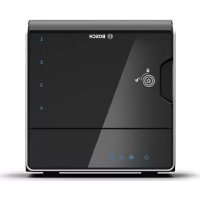
- DIVAR AN 3000 / DIVAR AN
- BOSCH
- SEQUENCE MON B
- OPERATING INSTRUCTIONS
- WEB CLIENT SOFTWARE
- ARCHIVE PLAYER OPERATION
- TROUBLESHOOTING
- MAINTENANCE
- TECHNICAL SPECIFICATIONS
- APPENDIX
- SAFETY
- SAFETY PRECAUTIONS
- IMPORTANT SAFETY INSTRUCTIONS
- IMPORTANT NOTICES
- NOTICE
- CAUTION
- CLASS I LASER PRODUCT
- COAX GROUNDING
- RACK-MOUNT (ONLY DIVAR 5000 FAMILY)
- FCC AND UL
- FCC & ICES INFORMATION
- UL DISCLAIMER
- BOSCH NOTICES
- COPYRIGHT
- TRADEMARKS
- NOTE
- SHORT INFORMATION
- H HIGH RESOLUTION
- COMPRESSION TECHNOLOGY
- INTRODUCTION
- DIGITAL VIDEO RECORDER APPLICATIONS
- RECORDING
- DOME CONTROL
- ALARMS
- LOCAL CONTROL
- NETWORK CONTROL
- SMARTPHONE APP
- VERSIONS
- MANUALS
- FEATURES
- UNPACKING
- PACKAGE CONTENTS
- INSTALLATION ENVIRONMENT
- MOUNTING
- VENTILATION
- TEMPERATURE
- POWER SUPPLY
- ENVIRONMENT
- ASSOCIATED EQUIPMENT
- WARRANTY
- QUICK INSTALL
- CONNECTIONS
- PRIMARY CONNECTIONS
- OPTIONAL CONNECTIONS
- POWERING UP
- FOR THE DIVAR
- LOGIN
- STARTUP WIZARD
- RESET STARTUP WIZARD
- GENERAL
- ENCODER
- SCHEDULE
- RECORD
- NETWORK
- SHUTDOWN/LOGOUT
- LOGOUT WITH POWER BUTTON
- AUTO RESUME AFTER POWER FAILURE
- HARDWARE SETUP
- CAMERA CONNECTIONS
- SPECIFICATIONS
- AUDIO CONNECTIONS
- MONITOR CONNECTIONS
- VGA OUTPUT
- CVBS
- HDMI
- KEYBOARD CONNECTION (ONLY DIVAR 5000)
- CONNECTION
- ETHERNET CONNECTION
- RS485 PORT CONNECTION
- RS232 PORT CONNECTIONS
- USB CONNECTORS
- E-SATA CONNECTOR (ONLY DIVAR 5000)
- ALARM I/O CONNECTIONS
- CONNECTING THE ALARM INPUT
- CONNECTING THE ALARM OUTPUT
- DANGER
- DIVAR
- CONFIGURATION
- SETTING
- SYSTEM TIME / GMT
- DATE FORMAT
- DST (DAYLIGHT SAVING)
- DATE SEPARATOR
- TIME FORMAT
- LANGUAGE
- VIDEO STANDARD
- DEVICE NO
- DEVICE ID
- HDD FULL
- PACK DURATION
- REALTIME PLAY
- HOLIDAY
- STARTUP WIZARD AFTER SYSTEM RESTART
- MOUSE PROPERTY
- AUTO LOGOUT
- ENCODE
- OVERLAY
- SNAPSHOT
- SCHEDULE)
- ACTIVATE SNAPSHOT
- PRIORITY
- SEE ALSO
- COPY
- EDIT A SCHEDULE
- SERIAL PORT
- RS232 SERIAL PORT
- BOSCH KEYBOARD
- NETWORK SETTINGS
- IP FILTER
- ENABLE
- TYPE
- START ADDRESS / END ADDRESS
- NTP
- PPPOE
- DDNS
- UPNP
- SMTP SERVER
- SMTP PORT NUMBER
- ANONYMOUS
- USER NAME AND PASSWORD
- RECEIVER
- SENDER
- SUBJECT
- ENCRYPT TYPE
- EVENT INTERVAL
- HEALTH ENABLE
- INTERVAL
- FTP SERVER
- SNMP
- ALARM
- DETECT
- MOTION DETECT REGION SETUP
- PERIOD
- PTZ ACTIVATION
- PAN/TILT/ZOOM
- DISPLAY
- TOUR SETUP
- DEFAULT
- ADVANCED
- HARD DISK (HDD)
- SYSTEM EVENTS
- ALARM OUTPUT
- ACCOUNT/USERS
- ADD USER
- MODIFY/DELETE A USER
- MODIFY PASSWORD
- AUTO MAINTAIN
- TV ADJUST
- TEXT DATA OVERLAY
- NET TYPE
- FIGURE 6.39: TEXT DATA OVERLAY NET
- COM TYPE
- ATM/POS
- CONFIGURATION/BACKUP
- SEQUENCE MONITOR B
- USER CONTROLS AND MENUS
- FRONT PANEL CONTROLS
- REMOTE CONTROL
- QUICK MENU
- MAIN MENU
- LIVE AND PLAYBACK
- LIVE MODE
- CHANGING THE DISPLAY
- PLAYBACK AND ZOOM
- PTZ
- SEQUENCE
- ACTIVATE SEQUENCE ON MONITOR A
- SEQUENCE OFF
- MONITOR A
- MONITOR B
- SEARCH/PLAY
- BACKUP
- BACKUP SELECT SCREEN
- INFO
- HDD INFO
- BPS
- LOG
- HOW TO USE LOG DISPLAY
- VERSION
- ONLINE USERS
- NETWORK INFO
- NETWORK TEST
- TRIGGERS AND ALARMS
- BACKGROUND EVENTS
- GETTING STARTED
- SYSTEM REQUIREMENTS
- CONNECTING TO THE DIVAR THE FIRST TIME
- HOW TO LOG ON
- MENU STRUCTURE DIFFERENCES
- INTRODUCING THE WEB LIVE WINDOW
- IMPORTANT
- PLAYBACK MODE
- SETUP MODE
- LOGOUT
- INSTALLATION
- STARTING THE PLAYER
- OPEN AN ARCHIVE FILE
- PLAYER CONTROL
- SET
- CAMERA VIEWS
- RESOLUTION
- FULL SCREEN
- CHECKING AUTHENTICITY (WATERMARK)
- EXIT BUTTON
- CANNOT BOOT UP CORRECTLY
- DVR AUTOMATICALLY SHUTS DOWN OR STOPS RUNNING
- SYSTEM CANNOT DETECT HARD DISK
- NO VIDEO OUTPUT (ON ONE-CHANNEL, MULTIPLE-CHANNEL OR ALL-CHANNEL OUTPUT)
- REAL-TIME VIDEO COLOR IS DISTORTED
- CANNOT SEARCH LOCAL RECORDS
- VIDEO IS DISTORTED WHEN SEARCHING LOCAL RECORDS
- THERE IS NO AUDIO WHEN MONITORING
- THERE IS AUDIO WHEN MONITORING BUT THERE IS NO AUDIO DURING PLAYBACK
- TIME DISPLAY IS INCORRECT
- DVR CANNOT CONTROL PTZ
- MOTION DETECTION FUNCTION DOES NOT WORK
- CANNOT LOG IN CLIENT-END OR WEB
- NO VIDEO (ONLY MOSAIC) DURING REMOTE PREVIEW OR PLAYBACK OF VIDEO FILE
- NETWORK CONNECTION IS INSTABLE
- BURN ERROR / USB BACKUP ERROR
- KEYBOARD CANNOT CONTROL DVR
- ALARM SIGNAL CANNOT BE DISARMED
- ALARM FUNCTION IS NULL
- REMOTE CONTROL DOES NOT WORK
- RECORD STORAGE PERIOD IS TOO SHORT
- CANNOT PLAYBACK THE DOWNLOADED FILE
- FORGOTTEN LOCAL MENU OPERATION PASSWORD OR NETWORK PASSWORD
- PRECAUTION - ELECTRICAL VOLTAGE
- PRECAUTION - CONNECTOR DAMAGE
- PRECAUTION - PROCESSOR/WIRING DAMAGE
- ATTACH ESD STRAP
- REPLACE INTERNAL BATTERY
- INSTALL HDD IN DIVAR
- INSTALL HDD
- INSTALL HDD 3 AND
- INSTALL DVD IN DIVAR
- SOFTWARE LICENSES
- BOSCH SOFTWARE
- OTHER LICENSES – COPYRIGHT NOTICES
- WARRANTIES AND DISCLAIMER OF WARRANTIES
- DVD COMPATIBILITY
- USB MEMORY STICKS
- HDD COMPATIBILITY
- WARRANTY AND SUPPORT ISSUES
- LEGAL NOTE
Brand : BOSCH
Model : DIVAR AN 5000
Category : Voice recorder