
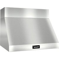
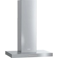
DA 3590 - Range hood MIELE - Free user manual and instructions
Find the device manual for free DA 3590 MIELE in PDF.


| Product Type | Built-in range hood |
| Brand | Miele |
| Model | DA 3590 |
| Width | 90 cm |
| Depth | 50 cm |
| Height | 60-110 cm (adjustable chimney) |
| Weight | Approx. 25 kg |
| Power Supply | 230 V, 50 Hz |
| Rated Power | 280 W |
| Extraction Rate | Max. 700 m³/h (free air) |
| Noise Level | 37-65 dB(A) depending on speed |
| Filter Type | Grease filter (metal mesh) and optional charcoal filter |
| Grease Filter Material | Stainless steel, dishwasher safe |
| Lighting | 2 x 2.5 W LED, dimmable |
| Controls | Touch control panel with speed selection |
| Speeds | 4 fan speeds + intensive boost |
| Air Vented | Ducted or recirculation mode |
| Duct Diameter | 150 mm |
| Energy Efficiency Class | B (EU) |
| Safety Features | Automatic shut-off timer, motor protection |
| Maintenance | Grease filter cleaning every 4-6 weeks, charcoal filter replacement every 6-12 months |
| Spare Parts | Grease filter (Miele 09710080), charcoal filter (Miele 09710070), LED lamp |
| Repairability Index | 8.4/10 (estimated) |
| Certifications | CE, CB |
Frequently Asked Questions - DA 3590 MIELE
User questions about DA 3590 MIELE
0 question about this device. Answer the ones you know or ask your own.
Ask a new question about this device
Download the instructions for your Range hood in PDF format for free! Find your manual DA 3590 - MIELE and take your electronic device back in hand. On this page are published all the documents necessary for the use of your device. DA 3590 by MIELE.
USER MANUAL DA 3590 MIELE
Operating and installation instructions
natural_image
Illustration of a pot with steam rising from its side, no text or symbols presentCooker hood
DA 3560
DA 3590
DA 3560 EXT
DA 3590 EXT
To avoid the risk of accidents or damage to this appliance, it is essential to read these instructions before it is installed and used for the first time.
en - GB
M.-Nr. 09 466 100
Contents
Caring for the environment....3
Warning and Safety instructions 4
Guide to the appliance 10
Description of the functions 12
Miele@home 13
Con@ctivity 13
Operation 14
To switch the fan on....14
To select a power level 14
Intensive setting 14
Run-on option 5 ⚠15 …… 15
To switch the fan off....15
Hob lighting 15
Filter operating hours counter 16
Cleaning and care 18
Housing 18
Grease filters 19
Resetting the grease filter operating hours counter 20
Fitting and replacing the charcoal filters 21
Resetting the charcoal filter operating hours counter 21
Changing a halogen lamp 22
After Sales Service 23
Appliance dimensions....24
Installation 26
Installation accessories 26
Adjusting the deflector plate....34
Connection for air extraction 38
Condensate trap 39
Silencer 40
Electrical connection 41
Operation with Control module DSM 400 42
Potential free connection 42
Connection to a push button switch 42
Technical data 43
Disposal of the packing material
The transport and protective packing has been selected from materials which are environmentally friendly for disposal, and should be recycled.
Packaging e.g. cling film, polystyrene and plastic wrappings must be kept out of the reach of babies and young children. Danger of suffocation!
Disposal of your old appliance
Electrical and electronic appliances often contain materials which, if handled or disposed of incorrectly, could be potentially hazardous to human health and to the environment. They are, however, essential for the correct functioning of your appliance. Please do not therefore dispose of it with your household waste.

natural_image
Symbol of a trash bin crossed with no text or numbers, representing environmental protection (no text present)Please dispose of it at your local community waste collection / recycling centre or contact your dealer for advice. Ensure that it presents no danger to children while being stored for disposal.
This appliance complies with all relevant local and national safety requirements. Inappropriate use can, however, lead to personal injury and damage to property.
To avoid the risk of accidents and damage to the appliance, please read these instructions carefully before using it for the first time. They contain important information on the safety, installation, use and maintenance of the appliance.
Keep these instructions in a safe place and ensure that all users are familiar with the contents. Pass them on to any future owner of the appliance.
Correct application
This appliance is not designed for commercial use. It is intended for use in domestic households and in similar working and residential environments such as:
- Shops
- Offices and showrooms
and by residents in establishments such as
- Hostels and guesthouses
It must only be used as a domestic appliance to extract vapours and remove odours from cooking.
The cooker hood is not intended for outdoor use.
Any other usage is not supported by the manufacturer and could be dangerous. Miele cannot be held liable for damage resulting from incorrect or improper use or operation of the appliance.
This appliance is not intended for use by people with reduced physical, sensory or mental capabilities, or lack of experience or knowledge, unless they are supervised whilst using it or have been shown how to use it correctly by a person responsible for their safety.
Safety with children
This appliance is only intended for use by adults who have read these instructions.
This appliance is not a toy! To prevent the risk of injury do not let children play with the appliance or its controls.
Children under 8 years of age must be kept away from the cooker hood unless they are constantly supervised.
Children 8 years and older may use the cooker hood only if they have been shown how to use it in a safe way and understand the hazards involved.
▶ Please be aware that on cooker hoods with halogen lighting, the lamps will get very hot during use and remain hot for some time after switching off. To safeguard against burning, keep children well away from the lamps at all times.
Technical safety
Before installation, check the cooker hood for visible signs of damage. Under no circumstances should you use a damaged appliance. It could be dangerous.
Before connecting the appliance to the mains supply, make sure that the voltage and frequency details given on the data plate correspond with the on-site electricity supply, otherwise the appliance could be damaged. Consult a qualified electrician if in any doubt.
The electrical safety of this appliance can only be guaranteed if it is correctly earthed. It is most important that this basic safety requirement is present and tested regularly, and where there is any doubt, the household wiring system should be inspected by a qualified electrician. The manufacturer cannot be held liable for the consequences of an inadequate earthing system (e.g. electric shock).
For safety reasons, this appliance may only be used when it has been fully installed.
▶ Only open the housing as described in the instructions given in the installation sheet and in the Cleaning and care section of this booklet. Under no circumstances should any other parts of the housing be opened. Tampering with electrical connections or components and mechanical parts is highly dangerous to the user, and can cause operational faults.
▶ Installation, maintenance and repairs may only be carried out by a Miele authorised person in accordance with current national and local safety regulations.
Repairs and other work by unqualified persons could be dangerous. The manufacturer cannot be held liable for unauthorised work.
▶ Faulty components must only be replaced by genuine Miele original parts. The manufacturer can only guarantee the safety of the appliance when Miele replacement parts are used.
During installation, maintenance and repair work, the appliance must be disconnected from the mains electricity supply.
Warning and Safety instructions
Do not connect the appliance to the mains electricity supply by a multi-socket unit or an extension lead. These do not guarantee the required safety of the appliance (e.g. danger of overheating).
For appliances with an external fan motor fitted (...EXT models) the connection of the two units must be made using the connection cable and the plug connectors. These models may only be combined with a Miele external motor.
This appliance must not be used in a non-stationary location (e.g. on a ship).
In areas which may be subject to infestation by cockroaches or other vermin, pay particular attention to keeping the appliance and its surroundings in a clean condition at all times. Any damage which may be caused by cockroaches or other vermin will not be covered by the guarantee.
Using at the same time as other heating appliances that depend on the air from the room
Warning - danger of toxic fumes
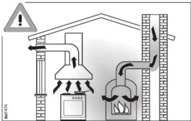
▶ Great care should be taken when using the cooker hood at the same time and in the same room or area of the house as another heating appliance which depends on the air in the room. Such appliances include gas, oil, wood or coal-fired boilers and heaters, continuous flow or other water heaters, gas hobs, cookers or ovens which draw air in from the room and duct exhaust gases out through a chimney or extraction ducting.
When used in extraction mode, with or without an external motor fitted, the appliance draws air in from the room in which it is installed and from neighbouring rooms.
If there is insufficient air, an underpressure will occur. The heating appliance may be starved of oxygen, impairing combustion.
Harmful gases could be drawn out of the chimney or extraction ducting back into the room, with potentially fatal consequences.
In order to ensure safe operation, and to prevent gases given off by the heating appliances from being drawn back into the room when the cooker hood and the heater are in operation simultaneously, an underpressure of 0.04 mbar (4 pa) is the maximum permissible in the room.

natural_image
Diagram of a greenhouse gasifier with cooling fans, heat exchangers, and exhaust pipe (no text or labels)Ventilation can be maintained by air inlets which must not be blocked, in windows, doors and outside wall vents, or by other technical measures, such as ensuring that the cooker hood can only be switched on when the heating appliance is switched off or vice versa. A ventilation brick alone is not generally sufficient to ensure safe ventilation.
The overall ventilation condition of the dwelling must be taken into account. If in any doubt, the advice of a competent builder or, for gas, a qualified gas fitter (GasSafe registered in the UK) must be sought.
If the hood is being operated in recirculation mode, the above restrictions do not apply.
Correct use
▶ Never use an open flame beneath the cooker hood. To avoid the danger of fire, do not flambé or grill over an open flame.
When switched on, the cooker hood could draw flames into the filter. Fat particles drawn into the cooker hood present a fire hazard.
When using the cooker hood over a gas hob, ensure that any burners in use are always covered by a pan. Switch the cooking zone off when a pan is removed, even for a short time.
Regulate the flame so that it does not burn up the sides of the pan.
Do not allow the pans to overheat excessively (e.g. when using a wok). The cooker hood can become damaged when exposed to excessive heat.
▶ Always switch the cooker hood on when a cooking zone is in use, otherwise condensation may collect in the hood, which could cause corrosion.
When cooking with oil or fat, chip pans and deep fat fryers etc, do not leave the pans unattended. Never leave an open grill unattended when grilling. Overheated oil and fat can ignite and could set the cooker hood on fire.
Do not use the cooker hood without the filters in place. This way you will avoid the risk of grease and dirt getting into the appliance and hindering its smooth operation.
The filters should be regularly cleaned or changed as appropriate. Saturated filters are a fire hazard. See "Cleaning and care".
The cooker hood can get very hot during cooking due to heat rising from the hob.
Do not touch the housing or the grease filters until the cooker hood has cooled down.
Do not use a steam-cleaner to clean this appliance. Steam could reach electrical components and cause a short circuit.
Correct installation
▶ Refer to the cooker or hob manufacturer's instructions as to whether a cooker hood may be operated above the cooker/hob.
The minimum safety distances between the top of the cooker or hob and the bottom of the cooker hood given in the "Appliance dimensions" section of this booklet must be maintained, unless the hob manufacturer states that a greater safety distance is required.
If more than one cooking appliance is fitted beneath the cooker hood, and they have different minimum safety distances to the cooker hood, select the greater distance.
▶ Safety regulations prohibit the fitting of a cooker hood over solid fuel stoves.
All ducting, pipework and fittings must be of non-flammable material. These can be obtained from the Miele Spare Parts department or from builders' merchants.
The appliance must not be connected to a chimney or vent flue which is in use. Neither should it be connected to ducting which ventilates rooms with fireplaces.
If exhaust air is to be extracted into a chimney or ventilation duct no longer used for other purposes, seek professional advice.
Accessories
▶ Only use genuine Miele spare parts and accessories with this appliance. If spare parts or accessories from other manufacturers are used, this will invalidate the guarantee, and Miele cannot accept liability.
The manufacturer cannot be held liable for damage caused by non-compliance with these Warning and Safety instructions.
Guide to the appliance

natural_image
Line drawing of a rectangular box with a side panel and a small curved mark on the front face (no text or symbols)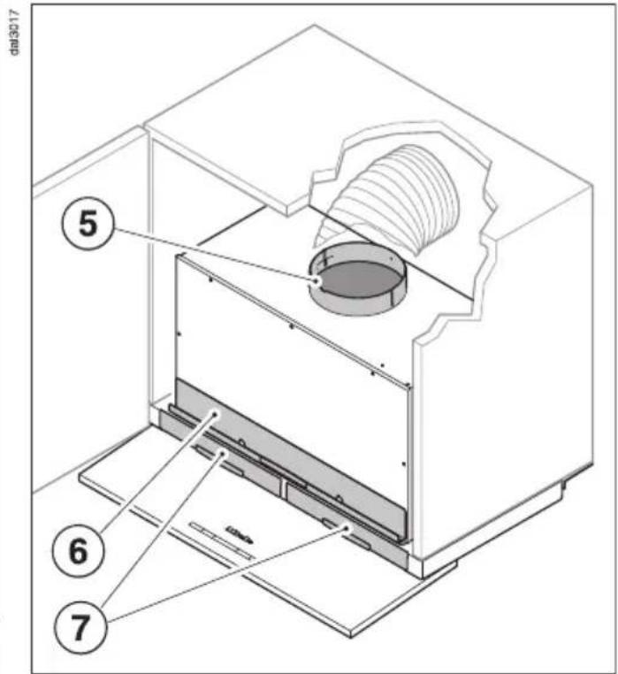

| -123IS+ | 515 | |||
| 9 | 10 | 11 | 12 | 13 |
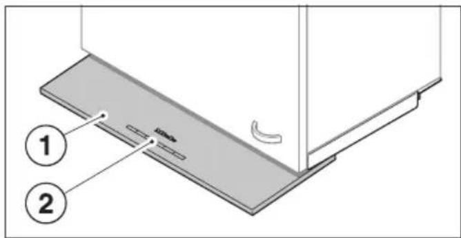
① Pull-out deflector plate
② Controls
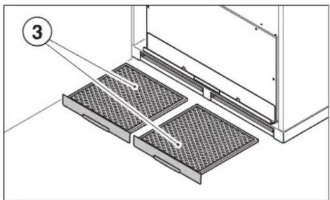
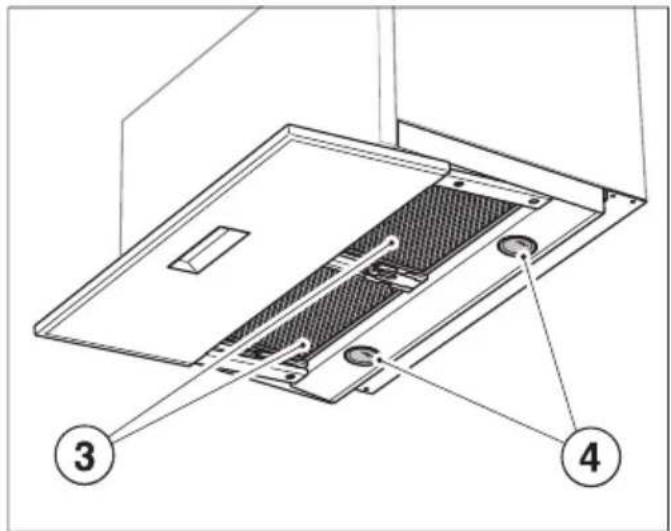
③ Grease filters
④ Hob lighting
⑤ Exhaust socket ∅ 150 mm
The exhaust socket can also be fitted at the back.
⑥ Slots for the charcoal filters
⑦ Slots for the grease filters
⑧ Charcoal filters
(extra accessory available to order for recirculation mode)
⑨ Hob lighting button
This button can be used to switch the hob lighting on and off and is also a dimmer switch.
⑩ On/Off button for the fan
⑪ Buttons for selecting the fan power level
⑫ Button for the run-on option
The fan can be set to switch off automatically after either 5 or 15 minutes.
⑬ Operating hours button
The grease filter symbol ⚙ for the operating hours button lights up when the grease filters need to be cleaned.
The charcoal filter symbol ⚙ lights up when the charcoal filters used in recirculation mode need to be replaced. For this to happen, the operating hours counter needs to be activated before the appliance is used for the first time.
The button is used to reset the appropriate operating hours counter each time the grease filters are cleaned or the charcoal filters have been replaced (see "Cleaning and care").
It can also be used to check and alter the operating hours counter.
For information about using the appliance, see "Operation".
The cooker hood works with
... air extraction:
The air is drawn in, cleaned by the grease filters and directed outside.
If the on-site ventilation system does not have a non-return flap, then the non-return flap supplied with the appliance must be fitted in the exhaust socket of the motor unit.
Having a non-return flap fitted in the ducting ensures that air, once ducted to the outside, cannot get back into the room again.
The flap is closed when the cooker hood is switched off.
When the cooker hood is switched on, the non-return flap opens for the cooking vapours to be blown directly outside.
... air recirculation:
(air recirculation conversion kit required)
The air is drawn in and cleaned first by the grease filters and then by two charcoal filters. The cleaned air is then recirculated back into the kitchen.
The charcoal filters are available to order through your Dealer or Miele (see back page for contact details and Technical data for part number).
Before using the cooker hood in recirculation mode, ensure that the charcoal filters are in place. See "Cleaning and care".
... a n external motor:
(...EXT models only)
EXT models are designed to be connected to an external motor located outside the room.
The external motor is connected to the cooker hood by means of a control cable, and is operated by the controls on the cooker hood.
Con@ctivity

flowchart
graph TD
    A["① Battery Pack"] --> B["+ Laptop"]
    C["② Motor"] --> D["+ Electric Power Supply"]
    E["③ Power Supply"] --> F["Ground"]
This cooker hood is communication enabled.
Communication module XKM 2000 DA ①, available as an optional extra, enables the operation of the cooker hood to be automatically controlled by the operating status of a Miele electric hob with onset controls.
For communication to take place, the hob must be fitted with communication module XKM 2000 KM ②.
The hob transmits information about its operating status to the cooker hood via the household power supply (Powerline) ③.
The communication module is fitted to the housing of the cooker hood and is connected to the controls of the cooker hood.
The module must be installed by a Miele service technician or suitably qualified electrician.
Automatic operation
■ With the deflector plate pushed in on the cooker hood, switch on the hob. The hob lighting will switch on automatically.
■ Then pull the deflector plate out. The cooker hood fan will switch on.
During cooking, the cooker hood automatically sets its power level according to the number of cooking zones in operation and their power levels. You can still operate the cooker hood manually at any time.
After the hob has been switched off, the cooker hood fan and hob lighting will switch off automatically after a period of time.
If the deflector plate remains pulled out, the cooker hood will switch on automatically the next time the hob is switched on.
Manual operation
■ If you want to operate the cooker hood manually, pull the cooker hood deflector plate out before switching on the hob.
Proceed as described in "Operation".
For detailed information about this function, please read the separate instruction booklet supplied with the XKM 2000 DA communication module.
natural_image
Illustration of a hand using a tool to interact with a small object on a flat surface (no text or symbols)■ Pull the deflector plate downwards slightly and then towards you.
The fan will come on at power level 2. The On/Off symbol ① and Fan setting 2 will light up.
To select a power level
■ Press the – symbol to select a lower power level or the + symbol to select a higher power level.
Depending on the intensity of the cooking vapours, levels 1 to 3 are usually sufficient for normal cooking.
Intensive setting
■ For short periods of strong vapours and cooking odours, e.g. whilst searing meat, select the IS or Intensive setting.
Pull the deflector plate out to its full extent to gain maximum extraction whilst avoiding excessive noise levels.
Automatic switch-off of the Intensive setting
You can set the Intensive setting so that it always only runs for 10 minutes before reverting automatically to level 3.
■ Pull the deflector plate out and switch off the fan ① and the lighting ⚙.
■ Press the Run-on option button 5 ⚠15 for approx. 10 seconds, until the 1 lights up.
■ Then press in turn – - the lighting button ⚙-, - the – button, and - the lighting button ⚙.
If Automatic switch-off is not activated, 1 and IS will flash.
- Press the + button to activate Automatic switch-off. Fan power levels 1 and IS will now light up constantly. Press the – button to deactivate the Automatic switch-off function.
■ Confirm your selection by pressing the Run-on option button 5 & 15.
If you do not confirm within 4 minutes, the cooker hood will automatically revert to the original setting.
Run-on option 5 ⚠15
It is advisable to run the fan for a few minutes after cooking has finished to neutralise any lingering odours in the air, whether you are using air extraction or recirculation mode.
The fan can be set to switch off automatically after 5 or 15 minutes.
■ After cooking has finished, press the Run-on option button 5 ⚠15 whilst the fan is still running
- Press once = The fan will switch off after 5 minutes (5 & will light up).
- Press twice = The fan will switch off after 15 minutes (215 will light up).
If you press the Run-on option button 5 🎩15 again, the fan remains on (5 🎩15 will go out).
■ Push the deflector plate back in. The next time the deflector plate is pulled out, the cooker hood will operate at power level 2 again.
or
■ Press the On/Off button Ⓐ for the fan.
All the indicator lights will go out.
Hob lighting
To switch the hob lighting on
■ Pull the deflector plate out.
or
■ Press the hob lighting button briefly
The ⚡ symbol lights up.
The hob lighting will switch on at maximum brightness.
To dim the hob lighting
The brightness of the hob lighting can be adjusted.
■ With the hob lighting switched on, press and hold the hob lighting button ⚙️.
The brightness will dim gradually until you release the button.
■ To increase the brightness, press and hold the hob lighting button -☀- in again until the level required is reached, then release it.
If you keep the hob lighting button pressed in ⚙, the lighting will continue to change between bright and dim.
To switch the hob lighting off
■ Push the deflector plate back in. or
■ Press the hob lighting button -☐-.
The ⚡ symbol will go out.
Safety switch-off
Should the cooker hood be left on, the fan will switch off automatically after 10 hours. The lighting will remain on.
■ Pressing the On/Off button Ⓐ will switch the fan back on again.
Filter operating hours counter 🎨
The number of hours the cooker hood has been in operation is stored in memory.
The Grease filter symbol 📍 or the Charcoal filter symbol Ⓧ will light up to tell you that the filters need to cleaned or changed.
See "Cleaning and care" for further information about cleaning and changing the filters and resetting the operating hours counters.
Altering the grease filter operating hours counter
You can set the operating hours counter to suit the type of cooking you do.
The operating hours counter is set at the factory for 30 hours.
Select a shorter time of 20 hours if you fry a lot.
If you only cook occasionally, we still recommend 20 hours because grease which has built up gradually over a long period of time will harden on the grease filters and make cleaning more difficult.
If you use very little fat for cooking, select a longer time of 40 or 50 hours.
To alter the operating time:
■ Switch the fan off by pressing the On/Off button ①.
■ Press the Run-on option button 5 & 15 and the operating hours button ⚙️ at the same time.
The Grease filter symbol ☐ of the operating hours button and one of the fan power levels will flash.
Fan power level indicator lights 1 to IS show the time set:
-
20 hours
-
30 hours
-
40 hours
IS 50 hours
- Press the – symbol to select a shorter operating time or the + symbol to select a longer operating time.
■ Confirm your selection by pressing the operating hours button 🔊.
All the indicator lights will go out.
If you do not confirm within 4 minutes, the cooker hood will automatically revert to the original setting.
Activating and altering the charcoal filter operating hours counter
(with recirculation mode)
The charcoal filters must be fitted for the cooker hood to be used in recirculation mode.
On delivery, the operating hours counter for the charcoal filter is deactivated.
For recirculation mode, the operating hours counter needs to be set to suit the type of cooking you do.
■ Switch the fan off by pressing the On/Off button ①.
■ Press the + symbol and the operating hours button ⚙️ on the control panel at the same time.
The Charcoal filter symbol ⚙ of the operating hours button and one of the fan power levels will flash.
Fan power level indicator lights 1 to IS show the time set:
- 120 hour
- 180 hours
- 240 hour
IS Deactivat
- Press the – symbol to select a shorter operating time or the + symbol to select a longer operating time.
■ Confirm your selection by pressing the operating hours button 🔒.
All the indicator lights will go out.
If you do not confirm within 4 minutes, the cooker hood will automatically revert to the original setting.
Checking the filter operating hours counter
To check the percentage of time set already used:
■ Switch the fan on with the On/Off button ①.
■ Press and hold the operating hours button Ⓦ:
- Once, to read the grease filter operating hours. The Grease filter symbol ⚙ will light up.
- Twice, to read the charcoal filter operating hours. The Charcoal filter symbol ⚙ will light up.
One or more of the power level indicators will flash at the same time.
The number of flashing indicator lights shows the percentage of the operating time which has already been used up:
- 25%
1 and 2 .... 50 %
1 to 3 75%
to IS 100%
The number of operating hours used remains in the memory, even when the cooker hood is switched off or there is a power cut.
⚠️ Before any cleaning or maintenance work is carried out, disconnect the cooker hood from the mains supply.
Exercise caution when changing halogen lamps. They get very hot during use and remain hot for some time after being switched off. The hot lamps are also susceptible to damage from damp cleaning. Wait a few minutes after switching off before commencing cleaning.
Housing
General
The surfaces and controls are susceptible to scratches and abrasion. Please observe the following cleaning instructions.
■ All external surfaces and controls can be cleaned using warm water with a little washing up liquid applied with a soft sponge.
■ Wipe the surfaces dry using a soft cloth.
Do not use too much water when cleaning the controls. Water could penetrate into the electronics and cause damage.
Avoid:
- cleaning agents containing soda, acids, chlorides or solvents,
- abrasive cleaning agents, e.g. powder cleaners or cream cleaners and abrasive sponges, as well as pot scourers or sponges which have been used previously with abrasive cleaning agents. These will damage the surface material.
Important for appliances with stainless steel housing
(This infomation does not apply to the controls).
Stainless steel surfaces can be cleaned using Miele's non-abrasive cleaning agent for stainless steel, following the manufacturer's instructions on the packaging.
To help prevent re-soiling, Miele conditioning agent for stainless steel can also be used. Follow the instructions on the packaging.
Controls
The controls may suffer discolouration or damage if soiling is left on them for too long. Remove soiling straight away.
Please observe the General notes on cleaning earlier in this section.
Do not use stainless steel cleaning agents on the controls.
Grease filters
The re-usable metal grease filters in the appliance remove solid particles (grease, dust, etc.) from the kitchen vapours, preventing soiling of the cooker hood.
Clean the grease filters regularly but always clean them immediately if the Grease filter symbol ☒ of the operating hours button lights up.
We recommend cleaning them at least every 3-4 weeks. Otherwise grease which builds up on the grease filters over a long period of time can harden, making cleaning more difficult.
⚠️ An oversaturated filter is a fire hazard.
■ Push in the deflector plate.
To avoid damaging the filter or the hob below, make sure you hold the filter securely at all times when handling it.

natural_image
Diagram showing a hand inserting a grating into two compartments, with no visible text or symbols.■ Pull the filters out of the slots in the front of the cooker hood housing.
Cleaning the grease filters by hand
■ Clean the filters with a soft nylon brush in a mild solution of hot water and a little washing-up liquid. Do not use "neat" washing-up liquid.
Avoid:
- cleaning agents containing descaling agents,
- powder cleaners, cream cleaners or abrasive all-purpose cleaners.
- oven sprays.
Cleaning the grease filters in the dishwasher
■ Place the filters as upright as possible in the lower basket, with the short sides upright. Make sure that the spray arm can move freely.
■ Select a programme with a maximum temperature of 65^ C. If a Miele dishwasher is being used, select the Sensor wash programme.
■ Use a mild dishwasher detergent.
Depending on the dishwasher detergent used, cleaning the filters in a dishwasher can cause permanent discolouration to the surface.
However, this will not affect the functioning of the filters in any way.
■ After cleaning, leave the filters to dry on an absorbent surface before replacing them.
■ When removing the filters for cleaning, also clean off any residues of oil or fat from the now accessible housing to prevent the risk of these catching fire.
■ Push the grease filters back into position.
Resetting the grease filter operating hours counter
After cleaning, the operating hours counter needs to be reset.
■ Whilst the fan is switched on, press the operating hours button ⚙️ for approx. 3 seconds until only the 1 is flashing. The Grease filter symbol ⚙️ goes out.
If you want to clean the grease filters before the operating hours counter has reached its maximum:
■ Press the operating hours button ⚙️ for approx. 6 seconds until only the 1 is flashing.
Fitting and replacing the charcoal filters
If the cooker hood is connected for recirculation, two active charcoal filters (optional accessory) must be inserted in addition to the grease filters. The charcoal filters absorb normal kitchen odours
Charcoal filters can be obtained from your Dealer or Miele.
See back cover for contact details, and "Technical data" for type and reference number.
The slots for the charcoal filters are located above the grease filters.

natural_image
Diagram of a hand inserting a component into a metal bracket (no text or symbols visible)■ Remove the cover. It is held in place by magnets.

natural_image
Technical diagram of a mechanical assembly with two rectangular components and directional arrows indicating motion (no text or symbols)■ Push the charcoal filters into the slots.
■ Replace the lid.
■ When fitting the charcoal filters for the first time:
Activate the operating hours counter (see "Operation").
Always replace the charcoal filters immediately if
- the Charcoal filter symbol ⚙ of the operating hours button lights up,
or
– they are no longer effective at absorbing kitchen odours.
They should, however, be replaced at least every 6 months.
■ Used charcoal filters can be disposed of with normal household waste.
Resetting the charcoal filter operating hours counter
After replacing the charcoal filters, the operating hours counter needs to be reset.
■ To do this, with the fan switched on, press the operating hours button twice. Hold the second press for approx. 3 seconds until only the 1 is flashing.
The Charcoal filter symbol ⚙ will go out.
If you want to replace the charcoal filters before the operating hours counter has reached its maximum:
■ Press the operating hours control ☐ twice. Hold the second press for approx. 6 seconds until only the 1 is flashing.
Changing a halogen lamp
■ Before any cleaning or maintenance work, disconnect the cooker hood from the mains supply.
Exercise caution when changing halogen lamps. They get very hot during use and remain hot for some time after being switched off. Let them cool down before you change them.

natural_image
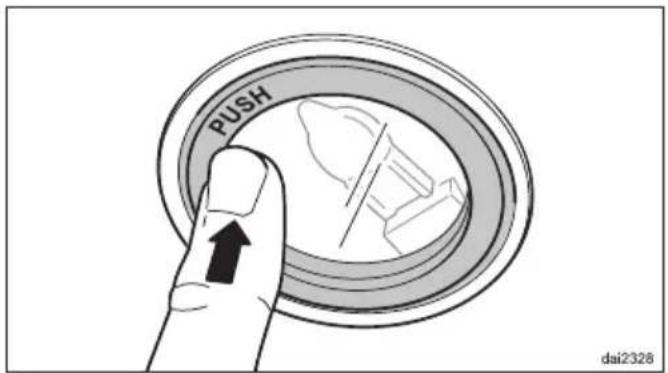
Cross-sectional diagram of a car head showing internal components and directional arrows (no text or labels)■ To access the halogen lamp press and release the lamp cover.
■ Pull the old halogen lamp out of the connection socket.
■ Using a cloth or glove, push the new lamp (12 V, 20 W, G4 cap) carefully into the connection socket. Please follow the manufacturer's instructions.
■ Push the cover back up and make sure it clicks into place.
In the event of a fault which you cannot correct yourself, or if the appliance is under guarantee, please contact:
- Your Miele Dealer / Chartered Agent or
- The Miele Service Department (see back cover for address).
When contacting your Dealer or Miele, please quote the model and serial number of your appliance. These are shown on the data plate which is visible when the grease filter is removed.
For the U.K.: Please note that telephone calls may be monitored and recorded for training purposes.
N.B. A call-out charge will be applied for service visits where the problem could have been resolved as described in these instructions.
Guarantee
For information on the appliance guarantee specific to your country please contact Miele. See back cover for contact details.
In the U.K. your appliance is guaranteed for 2 years from the date of purchase. However, you must activate your cover by calling 0845 365 6640 or registering online at www.miele.co.uk

1) Air extraction and recirculation mode with conversion kit DUU 150 if the air is to be directed upwards out of the wall unit.
2) Trim the wall unit carcase so that it is 38 mm shorter than the wall unit door.
3) Installation is also possible in a 600 mm wide unit.
4) The exhaust socket can also be fitted at the back.
5) After installation the wall unit can be fitted with an interim panel. If this is done make sure that the slots for the grease filters and the charcoal filters remain easily accessible.
6) If the wall unit has a base, openings must be provided to enable adjustment of the retaining force of the deflector plate. For example:
- The wall unit has side sections, as shown.
- The cooker hood is installed in a 600 mm wide wall unit with units at either side.
When measuring for the height of the wall housing unit and the cut-out, account must be taken of any accessories fitted, e.g. silencer, XKM module.
Safety distance between hob and cooker hood (S)
The following distance must be maintained between the top of the cooker/hob and the bottom of the cooker hood unless a greater distance is specified by the manufacturer of the cooker or hob:
450 mm: above electric hobs and cookers
650 mm: above gas hobs and cookers
650 mm: above an open grill or a deep fat fryer
See “Warning and Safety instructions” for further information.
Installation accessories
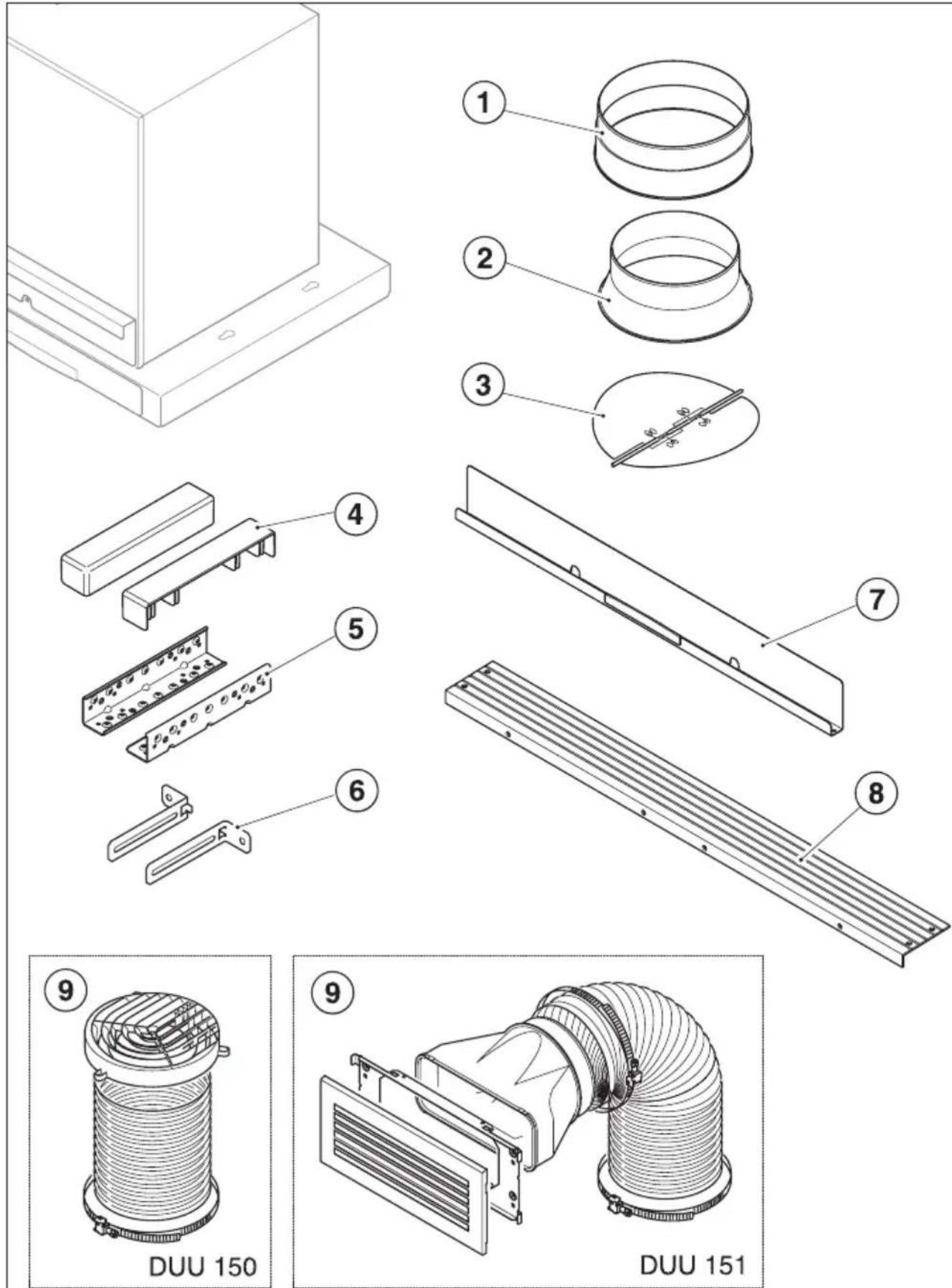
① 1 exhaust socket
for exhaust ducting ∅ 150 mm.
② 1 reducing collar
for exhaust ducting ∅125 mm.
③ 1 non-return valve
for fitting into the exhaust socket (not for recirculation mode).
④ 2 covers for the brackets
⑤ 2 brackets
to support the appliance in the wall unit.
⑥ 2 retaining brackets
for additional aligning and securing of the cooker hood in a 900 mm wide unit (DA 3590 only).
⑦ 1 cover
for the charcoal filter slots.
⑧ 1 spacer strip
to conceal the gap between the rear of the appliance and the wall.
⑨ Conversion kit for recirculation mode
(this is not supplied, but is available as an optional accessory - see "Technical data").
The kit contains an exhaust grille and flexible aluminium hose with clips.
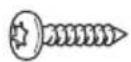
12 screws4x15mm
for securing the cooker hood into the wall unit.

4 screws M4 x 16 mm
for securing the cooker hood to the brackets and for securing the spacer strip.

4 screws M4x8mm
for securing the spacer strip.

natural_image
Technical line drawing of a screw and nut assembly (no text or symbols)2 screws 4 x 4 0 mm, 2 plugs6x36mm
for additional securing of the cooker hood to the wall (only when fitting the DA 3590 into a 900 mm wide unit).

4 screws4x25mm
for additionally securing the DA 3590 into a 600 mm wide unit.

4 adhesive covers
to conceal the fixing holes which are not required (DA 3590 only).

natural_image
Line drawing of a laboratory pipette with a bent tube and cap (no text or symbols)1 x T 2 0 angled key
⚠ Before installation, it is important to read the information given on the following pages as well as the Warning and Safety instructions at the beginning of this booklet. This is particularly crucial when using the cooker hood at the same time as a heating appliance that relies on oxygen from the same room, which could result in the build-up of toxic fumes.
Repositioning the venting connection
The motor unit can be rotated to allow the vent ducting to be fitted at the back of the cooker hood.
This may be necessary if the cooker hood is being fitted in a reduced height wall unit, for example.
Repositioning is carried out before installing the cooker hood.
⚠ The cooker hood must be disconnected from the mains electricity supply.
■ Undo the fixing screws on the front panel of the cooker hood housing and remove the panel.
■ Undo the screws on the cover on the back of the cooker hood housing and remove the cover.
■ Unscrew the fixing screws on the motor unit.
■ Turn the motor unit towards the rear and position the exhaust socket in the exhaust vent on the back panel of the cooker hood housing. Ensure when turning the motor unit that the connection cable does not become detached.
- Secure the motor unit in its new position.
■ Now secure the cover taken from the back panel to the top of the housing.
■ Refit the front panel and secure it using the screws.
EXT models
On appliances with an external motor (EXT models), the exhaust socket (not the motor unit) needs to be repositioned.
■ Unscrew the fixing screws and pull the top and bottom sections of the socket apart.
■ Position the top section of the socket over the exhaust vent on the back panel of the cooker hood housing and attach the bottom section to it from inside. Secure the exhaust socket with the fixing screws.

dai3029

■ Pull the grease filters out of the slots in the front of the cooker hood housing.
The spacer strip needs to be attached to the back of the cooker hood housing before the cooker hood is installed in the wall unit. The spacer strip can be attached to the upper ① or lower edge ② of the deflector plate.
■ Calculate measurement T for the spacer strip.
■ Cut the spacer strip to measurement T. Score along the groove for the smaller measurement as shown, and remove the surplus.
■ Screw the spacer strip to the back of the cooker hood at the required position. Use the screws supplied. To attach the spacer strip to the lower edge ② use the screws in the housing unit.

■ Screw the brackets onto the right and left inside walls of the housing unit so that they are flush with the bottom edge of the wall unit. The brackets are designed for 16 and 19 mm thick carcase sides. Orientate the bracket so that the vertical depth matches the thickness of the carcase side, as shown.
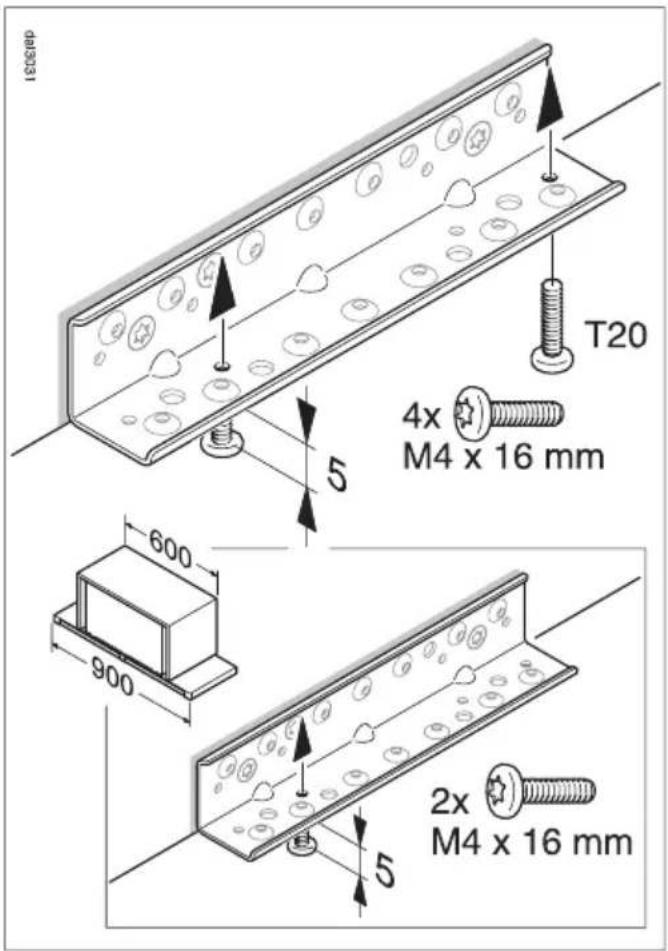
■ Fit the screws for attaching the cooker hood so that they protrude by about 5 mm, as shown.
Only use the front screws when fitting a 900 mm wide cooker hood in a 600 mm wide wall unit.

natural_image
Technical diagram of a mechanical assembly with directional arrows indicating movement, showing internal components and a close-up inset of a bolted joint (no text or symbols present)■ Fit the cooker hood into the wall unit from below, guiding it over the safety notch, as shown. Push it back until the spacer strip is flush with the wall.
natural_image
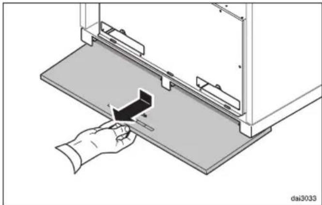
Diagram of a hand inserting a component into a device panel, showing mechanical components and alignment (no text or symbols)■ Pull the deflector plate downwards slightly and then towards you.
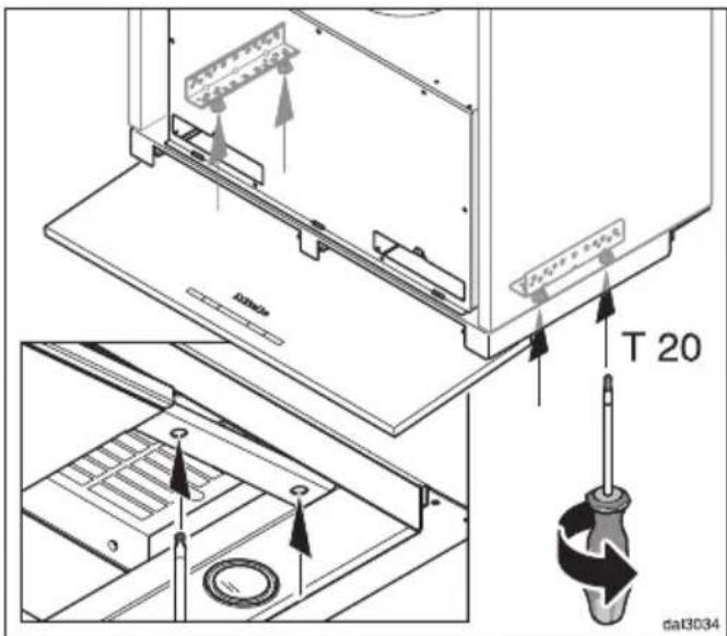
■ Tighten the four securing screws from below.
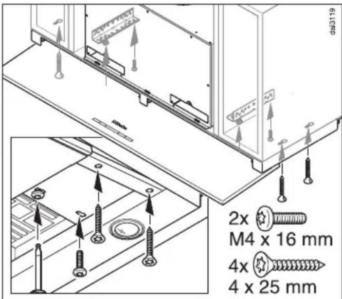
■ When fitting a 900 mm wide cooker hood in a 600 mm wide wall unit, insert the two rear screws at this stage. In this instance you will also need to secure it to the base on either side.
■ Push the deflector plate back in.

When fitting the DA 3590 in a 900 mm wide housing unit, the retaining brackets supplied are used to align the cooker hood and provide additional support.
The retaining brackets are secured either to the top or the back panel of the wall unit.
If the wall unit does not have a solid back panel, the cooker hood can be secured directly to the wall using the screws and plugs supplied.
The top housing screws are used to secure the retaining brackets to the cooker hood.
If the screws are difficult to access use the angled key supplied to tighten them.
■ Unscrew the appropriate housing screws.
■ Attach the retaining brackets loosely to the housing with the screws.
■ Align the cooker hood and mark the position of the fixing holes in the wall unit.
■ Now secure the brackets to the wall unit.
■ Realign the cooker hood and tighten up the screws on the housing unit.
■ Use the adhesive covers supplied to conceal the fixing holes which are not required.
Adjusting the deflector plate
(DA 3560, DA 3590)
When retracted, the deflector plate is held in place by magnets.
The retaining force of the magnets can be adjusted.
The magnets should be adjusted so that the deflector plate is held in place securely on the left and right hand side and can be lowered slightly.
An angled key is supplied for adjusting the magnets.

■ Adjust both sides equally. Turn in stages by half a turn each time and check the adjustment by lowering and raising the deflector plate.
- Turning the adjusting screws clockwise increases the magnetic retaining force.
- Turning the adjusting screws anti-clockwise reduces the magnetic retaining force.
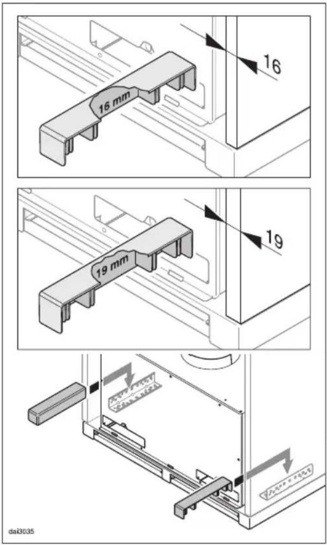
■ The covers for the brackets are designed for 16 mm and 19 mm thick carcase sides. Turn the covers so that they are in the appropriate position and fit them onto the brackets.
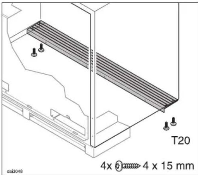
- Secure the spacer strip to the bottom of the wall unit as well.
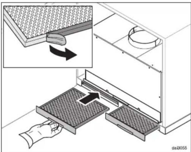
■ Take the grease filters out and remove any protective foil. Replace the grease filters.

natural_image
Technical diagram of a multi-level electronic device with a black arrow indicating rotation or assembly (no text or symbols present)■ Insert the cover for the charcoal filter slots as shown and close it. It is held in place by magnets.
Exhaust connection
natural_image
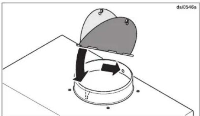
Diagram showing a rotating mechanical component with arrows indicating motion, no text or symbols present■ Insert the non-return flap, if required. Make sure that it opens easily and closes again by itself.

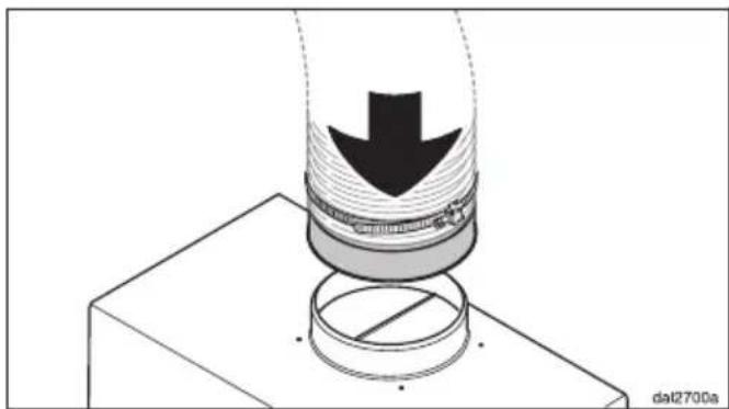
■ Attach the vent ducting to the exhaust socket, using e.g. a flexible hose and clips (available as an optional accessory). When using ∅ 125 mm ducting, fit the reducing collar supplied into the exhaust socket. (See "Connection for air extraction").
natural_image
Diagram of a mechanical assembly with a downward arrow and circular base (no text or symbols)■ Place the vent ducting onto the exhaust socket on the cooker hood.
■ See "Connection for air extraction" for further instructions on fitting the ducting.
Setting up for recirculation mode
If site conditions are not suitable for the cooker hood to be used with air extraction, the appliance must be set up for recirculation.
A conversion kit, available through your dealer or from Miele is required for operating the cooker hood in recirculation mode.
You will also need two charcoal filters (see "Technical data").

natural_image
Technical line drawing of a mechanical assembly with coiled spring and housing (no text or symbols)Conversion kit DUU 150 with a plastic grille is suitable for fitting in a non-visible area of the top of the wall unit.

natural_image
Technical illustration of a mechanical assembly with a coiled pipe and internal components (no text or symbols)Conversion kit DUU 151 with a stainless steel grille is recommended if the grille is to be fitted in an area which is visible.
■ Fit the conversion kit as described in the installation instructions supplied with the kit.
■ Make sure that the slats in the exhaust grille point towards the centre of the room and not towards a wall or the ceiling.
A non-return flap is not used in recirculation mode.
■ Fit the charcoal filters (see "Cleaning and care").
Electrical connection
Refer to the notes in "Electrical connection" and "Warning and Safety instructions" before connecting to the electricity supply.
■ For appliances connected to an external motor (EXT models): Connect the cooker hood to the external motor using the connecting cable and the 6-pole plug connector.
■ Connect the appliance to the electricity supply.
Important: To avoid the danger of toxic fumes, please observe the Warning and Safety instructions. This is especially crucial when using the cooker hood at the same time as another heating appliance which relies on air from the same room. The cooker hood should be installed according to local and national building regulations. Seek approval from the building inspector where necessary.
- Only use smooth pipes or flexible hoses made from non-flammable materials for the extraction ducting.
- When using an external motor, make sure that the exhaust ducting is sufficiently rigid. The external motor can cause an underpressure which can result in the exhaust ducting distorting.
To achieve the greatest possible air extraction with the lowest noise level, please note the following:
- To ensure efficient air extraction, the diameter of the exhaust ducting should not be less than 150 mm.
- If flat ducting is being used, the cross-section must not be smaller than the cross-section of the exhaust connection.
- All ducting, pipework and fittings must be of non-flammable materials.
- The exhaust ducting should be as short and straight as possible.
- Only use wide radius bends.
- The exhaust ducting should not be kinked or compressed.
- Ensure that all connections are strong and airtight.
- Where ducting is horizontal, it must be laid to slope away at at least 1 cm per metre. This is to ensure that condensate cannot drain back into the cooker hood.
- If the exhaust air is to be ducted into the open air, the installation of a telescopic wall vent or roof vent (available as an optional accessory) is recommended.

- If the exhaust air is to be ducted into a vent flue, the ducting must be directed in the flow direction of the flue.
Important:
If the exhaust ducting is to run through rooms, ceiling space etc. where there may be great variations in temperature between the different areas, the problem of condensation will need to be addressed. The exhaust ducting will need to be suitably insulated.
Condensate trap
(optional accessory)

In addition to insulating the exhaust ducting, we recommend that a suitable condensate trap is also installed to collect and evaporate any condensate which may occur. Condensate traps are available for ∅ 125 mm or ∅ 150 mm ducting.
When installing a condensate trap, ensure that it is positioned vertically and if possible directly above the exhaust connection. The arrow on the housing indicates the direction of air-flow.
Cooker hoods designed for use with an external motor (...EXT models) have an integrated condensate trap.
Silencer
(optional accessory)

To achieve even further reductions in noise levels, a special silencer can be fitted in the ducting system.

flowchart
graph TD
    A["1"] --> B["2"]
    B --> C["3"]
    C --> D["4"]
    D --> E["5"]
    style A fill:#f9f,stroke:#333
    style B fill:#ccf,stroke:#333
    style C fill:#cfc,stroke:#333
    style D fill:#fcc,stroke:#333
    style E fill:#ffc,stroke:#333
...with air extraction:
The silencer not only reduces noise from the fan, but also sounds from outside (e.g. traffic noise).
For this reason the silencer must be positioned as close as possible to the ducting exit ①.
...in recirculation mode:
The silencer needs to be positioned between the fan and the exhaust grille ②. The space needs to be checked in some cases.
...air extraction with external motor:
To minimise noise from the motor in the kitchen, the silencer should be positioned in front of the external motor ③ if possible, or if the ducting is long, then in the ducting inside the cooker hood itself ④.
In the case of an external motor placed inside the house, fitting a silencer behind the external motor ⑤ reduces the noise of the motor outside the house.
In all modes of operation, the most effective noise reductions are achieved if two silencers are fitted one behind the other in the system.
All electrical work should be undertaken by a suitably qualified and competent person in strict accordance with current national and local safety regulations (BS 7671 in the UK).
Installation, repairs and other work by unqualified persons could be dangerous, for which the manufacturer cannot be held liable.
Ensure power is not supplied to the appliance until after installation or repair work has been carried out.
Do not connect the appliance to the mains electricity supply by an extension lead. These do not guarantee the required safety of the appliance.
The connection data is given on the data plate. This is visible when the grease filters have been removed. Ensure that this data matches the household mains supply.
Connection of this appliance should be made via a suitable isolator or a double pole fused spur connection unit which complies with national and local safety regulations and the On-Off switch should be easily accessible after the appliance has been built in. When switched off there must be an all-pole contact gap of 3 mm in the switch (including switch, fuses and relays according to EN 60335).
If the switch is not accessible after installation (depending on country), an additional means of disconnection must be provided for all poles.
For extra safety it is advisable to protect the appliance with a suitable residual current device (RCD). Contact a qualified electrician for advice.
Important
This appliance is supplied for connection to an a.c. 230 V single phase 50 Hz supply.
The wires in the mains lead are coloured in accordance with the following code:
Green/yellow = earth Blue = neutral Brown = live
WARNING: THIS APPLIANCE MUST BE EARTHED
Operation with Control module DSM 400
The Miele DSM 400 control module (optional accessory) can be used to combine the cooker hood with other components.
It enables the following:
Potential free connection
This can be used to operate another appliance by pulling out the deflector plate and using the On/Off button ① of the cooker hood.
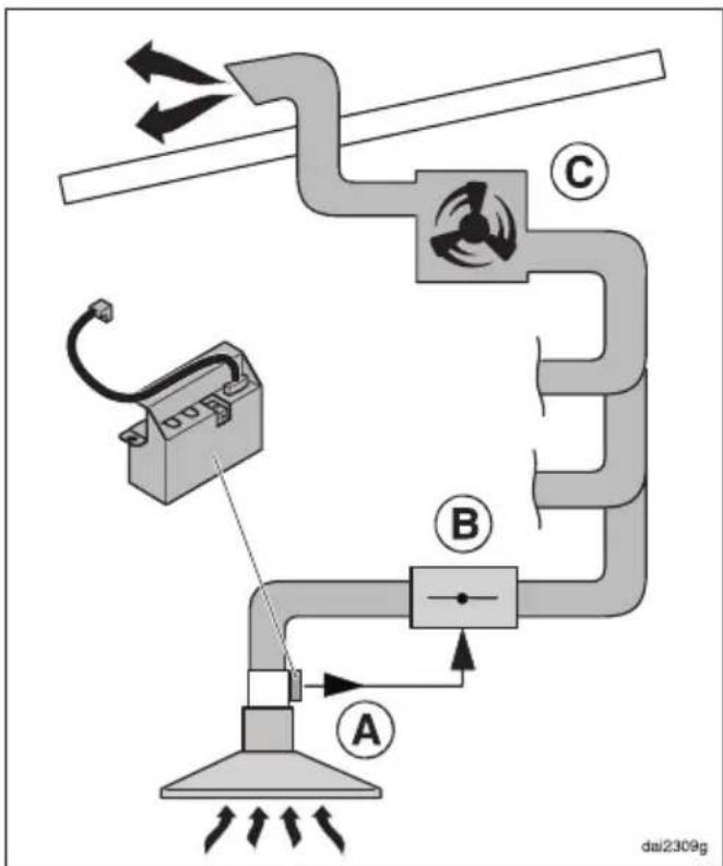
The potential free contact on the DSM 400 Ⓐ can, for example, be used in a cooker hood with an external motor ...EXT, which is connected to a central ducting system.
The contact can then be used to operate an electrically driven non-return flap Ⓑ which is connected to the central extraction unit ⓒ.
Components used in the central ducting system are not supplied by Miele.
If in any doubt, the advice of a competent builder or, for gas, a Gas Safe installer must be sought.
Connection to a push button switch
The control module can be used to switch on the cooker hood lighting when the deflector plate is pulled out via a push button switch in the house.
Installation
The control module must be installed at the back of the the cooker hood housing.
The electrical connection of components to the control module must be carried out by a suitably qualified and competent person.
Connected load*
DA 3560....170W
DA 3590....190W
Fan motor* 130 W
Hob lighting
DA 3560....2×20W
DA 3590....3×20W
Voltage A C 2 3 0 V
Frequency 50 Hz
Fuse rating 5 A
Electrical cable
length 1.5m
Weight
DA 3560....15kg
DA 3560 EXT .... 1 3 kg
DA 3590 18 kg
DA 3590 EXT .... 16 kg
Fan performance\*
Extraction power according to
EN 61591
Air extraction system ∅ 150 mm:
Level I....200m³/h
Level 2. . . . . . . . . . . . . . . . . . . . . . . . . 3 0 0 m³/h
Level 3. 400 m³/h
Intensive setting 640 m³/h
Recirculation power with charcoal filters:
Level I....150m³/h
Level 2. 2 3 0 m^3/h
Level 3. 320m³/h
Intensive setting .... 5 5 0 m³/h
Special accessories for recirculation mode:
- Conversion kit DUU 150 or DUU 151
- Miele charcoal filter set DKF 19-1. Contains two charcoal filters.
United Kingdom
Miele Co. Ltd.
Fairacres, Marcham Road
Abingdon, Oxon, OX14 1TW
Tel: 0845 365 0555
Fax: 0845 365 0777
Customer Contact Centre Tel: 0845 365 6600
E-mail: info@miele.co.uk
Internet: www.miele.co.uk
Australia
Miele Australia Pty. Ltd.
ABN 96 005 635 398
1 Gilbert Park Drive, Knoxfield, VIC 3180
Tel: 1300 464 353, Fax: (03) 9764 7149
Internet: www.miele.com.au
China
Miele (Shanghai) Trading Ltd.
1-3 Floor, No. 82 Shi Men Yi Road
Jing' an District
200040 Shanghai, PRC
Tel: +86 21 6157 3500
Fax: +86 21 6157 3511
E-mail: mieleshanghai@cn.miele.com
Miele (Hong Kong) Limited
41/F - 4101, Manhattan Place
23 Wang Tai Road
Kowloon Bay
Hong Kong
Tel: (852) 2610 1331
Fax: (852) 2610 1013
Email: mielehk@miele.com.hk
India
Miele India Pvt. Ltd.
Ground Floor, Copia Corporate Suites
Plot No. 9, Jasola
New Delhi - 110025
Tel: 011-46 900 000, Fax: 011-46 900 001
E-mail: customercare@miele.in
Internet: www.miele.in
Manufacturer: Miele & Cie. KG
Citywest Business Campus, Dublin 24
Tel: (01) 461 07 10, Fax: (01) 461 07 97
E-Mail: info@miele.ie, Internet: www.miele.ie
New Zealand
Miele New Zealand Limited
Unit L, 10-20 Sylvia Park Road
Mt. Wellington, 1060, Auckland, NZ
Tel: 0800 264 353, Fax: 0800 463 453
Internet: www.miele.co.nz
Singapore
Miele Southeast Asia
Miele Pte. Ltd.
163 Penang Road
# 04 - 02/03 Winsland House II
Singapore 238463
Tel: +65 6735 1191, Fax: +65 6735 1161
E-Mail: infosea@miele.com.sg
Internet: www.miele.sg
South Africa
Miele (Pty) Ltd
63 Peter Place, Bryanston 2194
P.O. Box 69434, Bryanston 2021
Tel: (011) 875 9000
Fax: (011) 875 9035
E-mail: info@miele.co.za
Internet: www.miele.co.za
United Arab Emirates
Miele Appliances Ltd.
P.O. Box 11 47 82
Gold & Diamond Park
Sheikh Zayed Road
Building 6 / Offices Nos. 6-214 to 6-220
Dubai
Tel: +971-4-341 84 44
Fax: +971-4-341 88 52

- Operating and installation instructions
- Contents
- Disposal of the packing material
- Disposal of your old appliance
- Correct application
- Safety with children
- Technical safety
- Warning and Safety instructions
- Using at the same time as other heating appliances that depend on the air from the room
- Correct use
- Correct installation
- Accessories
- Guide to the appliance
- ... air extraction:
- ... air recirculation:
- ... a n external motor:
- Con@ctivity
- To select a power level
- Intensive setting
- Automatic switch-off of the Intensive setting
- Run-on option 5 ⚠15
- Hob lighting
- To switch the hob lighting on
- To dim the hob lighting
- To switch the hob lighting off
- Safety switch-off
- Filter operating hours counter 🎨
- Altering the grease filter operating hours counter
- Activating and altering the charcoal filter operating hours counter
- Checking the filter operating hours counter
- Housing
- General
- Avoid:
- Important for appliances with stainless steel housing
- Controls
- Grease filters
- Cleaning the grease filters by hand
- Cleaning the grease filters in the dishwasher
- Resetting the grease filter operating hours counter
- Fitting and replacing the charcoal filters
- Resetting the charcoal filter operating hours counter
- Changing a halogen lamp
- Guarantee
- Safety distance between hob and cooker hood (S)
- screws4x15mm
- screws M4 x 16 mm
- screws M4x8mm
- screws 4 x 4 0 mm, 2 plugs6x36mm
- screws4x25mm
- adhesive covers
- Repositioning the venting connection
- EXT models
- Adjusting the deflector plate
- Setting up for recirculation mode
- Electrical connection
- Important:
- Condensate trap
- Silencer
- ...with air extraction:
- ...in recirculation mode:
- ...air extraction with external motor:
- Important
- Operation with Control module DSM 400
- Potential free connection
- Connection to a push button switch
- Installation
- Fan performance\*
- Special accessories for recirculation mode:
- United Kingdom
- Australia
- China
- Miele (Hong Kong) Limited
- India
- New Zealand
- Singapore
- South Africa
- United Arab Emirates
Brand : MIELE
Model : DA 3590
Category : Range hood