V12 Vanquish (2003) - Car Aston Martin - Free user manual and instructions
Find the device manual for free V12 Vanquish (2003) Aston Martin in PDF.

| Product Type | Sports car |
| Brand | Aston Martin |
| Model | V12 Vanquish |
| Year | 2003 |
| Engine | 6.0 L V12 |
| Power Output | 460 hp (343 kW) |
| Torque | 542 Nm |
| Transmission | 6-speed automated manual |
| Drivetrain | Front-engine, rear-wheel drive |
| Top Speed | 190 mph (306 km/h) |
| 0-60 mph | 4.5 seconds |
| Fuel Type | Petrol (gasoline) |
| Fuel Capacity | 80 L |
| Overall Length | 4665 mm |
| Overall Width | 1923 mm |
| Overall Height | 1320 mm |
| Wheelbase | 2690 mm |
| Curb Weight | 1,840 kg |
| Seating Capacity | 2 |
| Brakes | Ventilated discs (front and rear) |
| Tires | 255/40 R19 (front), 285/35 R19 (rear) |
| Maintenance | Refer to owner's manual for service intervals |
Frequently Asked Questions - V12 Vanquish (2003) Aston Martin
User questions about V12 Vanquish (2003) Aston Martin
0 question about this device. Answer the ones you know or ask your own.
Ask a new question about this device
Download the instructions for your Car in PDF format for free! Find your manual V12 Vanquish (2003) - Aston Martin and take your electronic device back in hand. On this page are published all the documents necessary for the use of your device. V12 Vanquish (2003) by Aston Martin.
USER MANUAL V12 Vanquish (2003) Aston Martin
V12 VANQUISH
Owner's Guide
Whilst every effort has been made to ensure the accuracy of the particulars contained in this Owner's Guide, neither the manufacturer nor the Dealer, by whom this Owner's Guide is supplied, shall in any circumstances be held responsible for any inaccuracy or the consequences thereof.
All rights reserved. No part of this publication may be reproduced, stored in a retrieval system or transmitted, in any form, electronic, mechanical, photocopying, recording or other means without prior written permission from Aston Martin Lagonda Limited.
The manufacturer reserves the right to vary specifications without notice in accordance with its policy of continual product improvement.
Produced by the Technical Publications Department
ASTON MARTIN LAGONDA LIMITED
Gaydon Engineering Centre, Banbury Road, Gaydon,
Warwick, CV35 0DB England
Telephone (+44) 01926 644700 Fax (+44) 01926 644733
Issue 3 - September 2003 Part Number (ROW) 4R12-403861-AA
Part Number (N. America) 4R12-403862-AA
Vehicle Provenance
Model
Colour ....
Body Exterior Interior Trim/ Piping
. . . . . . . . . . . . . . . . . . . . . . . . . . . . . . . . . . . . .
Interior Veneers
Vehicle Identification Number
As on the VIN plate
First Owner
Vehicle prepared for: ....
First Owner
By - Selling Dealer ....
Name
Date of Delivery ....
Date Delivered to First Owner
Second Owner
Name
Selling Dealer ....
Dealer Name
Date of Sale ....
Date Sold
V12 Vanquish Owner's Guide
Vehicle Provenance (continued)
Third Owner
Name
Selling Dealer....
Dealer Name
Date of Sale....
Date Sold
Fourth Owner
Name
Selling Dealer ....
Dealer Name
Date of Sale....
Date Sold
Fifth Owner
Name
Selling Dealer ....
Dealer Name
Date of Sale....
Date Sold
iv
Introduction
Vehicle Provenance iii
Warnings, Cautions and Notes vi
General Information vii
Reporting Safety Defects x
Regular Checks xi
Glossary of Terms xii
Section 1 - Owner's Guide
Before Driving 1-A-1
Driver Information 1-B-1
Controls 1-C-1
Driving 1-D-1
Heating, Ventilation & Air Conditioning 1-E-1
Security System 1-F-1
Owner Maintenance 1-G-1
Specifications 1-H-1
Section 2 - Audio / Satellite Navigation
Audio Guide 2-A-1
Satellite Navigation Guide 2-B-1
Section 3 - Service Schedules and Service Records
Service Schedules 3-A-1
Service Records 3-B-1
Section 4 - Warranty and Emergency Service
Warranty 4-A-1
Aston Martin Emergency Service 4-B-1
Section 5 - Dealer Directory
Aston Martin Lagonda Ltd. Dealer Directory 5-A-1
Section 6 - Index
Index 6-A-1
Warnings, Cautions and Notes
Within this Owner's Guide, advice is given at three levels, Warnings, Cautions and Notes. Take particular care to read all relevant advice before operating or servicing the vehicle.
Warnings
Procedures which must be followed precisely to help avoid the risk of personal injury.
Example:
WARNING: Avoid touching the sides of the engine when working in the engine compartment. The exhaust system will be hot if the engine has recently been run.
Cautions
Procedures which must be followed precisely to reduce the possibility of damage to the vehicle.
Example:
Caution: Take care that hydraulic fluid does not contact the paint work during the topping-up operation. Serious paint work damage can result. If a spillage does occur, immediately flush the hydraulic fluid from the paint work with clean, fresh water and then wipe with a clean damp cloth.
Notes
Procedures which will help to avoid difficulties in the operation of the vehicle.
Example:
Note: The ignition must be switched on (position I or II) before the door mirrors can be adjusted.
General Information
V12 Vanquish Owner's Guide
This Owner's Guide forms part of the essential vehicle equipment for homologation purposes and must remain with the vehicle at all times.
Important Safety Information
- Always wear your seat belt.
- Never drive under the influence of alcohol or drugs.
- Always obey all speed and traffic laws and regulations. Never drive faster than the posted speed limit or than conditions allow.
- Be particularly careful driving on slippery or wet surfaces.
- Your V12 Vanquish is a high performance car and has handling characteristics that you may not be accustomed to. Familiarise yourself with the car and always drive prudently, being aware of your own limitations and the limitations of the vehicle. As with other vehicles of this type, failure to operate the vehicle properly can result in accident and injury.
- Follow the maintenance schedule prescribed in this guide.
- Never allow your V12 Vanquish to be driven by inexperienced drivers.
- Never allow your V12 Vanquish to be worked on by unqualified individuals.
- To be sure that you are receiving qualified technical assistance using correct parts, have all service work performed by an Aston Martin Dealer.
Maintenance and Servicing
Regular maintenance and servicing is the responsibility of the owner. Regular routine maintenance helps to prevent unnecessary breakdowns and inconvenience. Each vehicle is given a full Pre-Delivery Inspection to ensure that all systems function correctly and that the vehicle meets its specifications. Failure to carry out maintenance at the recommended intervals could result in deterioration of vehicle performance and possible infringement of regulations. Such lack of proper maintenance may also adversely affect your warranty protection.
Your Aston Martin Dealer will arrange for appointments on a distance or time interval basis to ensure that all routine and corrective maintenance work is undertaken and recorded in the 'Service Schedules and Service Records' section of this Owner's Guide.
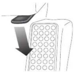
Location of Components
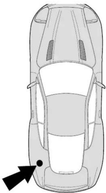
natural_image
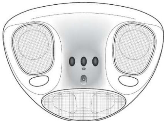
Top-down line drawing of a car showing front and rear views with a black arrow pointing to the side (no text or symbols)When reading component descriptions or when following procedures in this Owner's Guide, the following convention is adopted for locating items within the vehicle.
All directions are described as viewed from the driver's seat.
Thus the fuel filler cap indicated on this diagram would be described as "located at the rear left side of the vehicle".
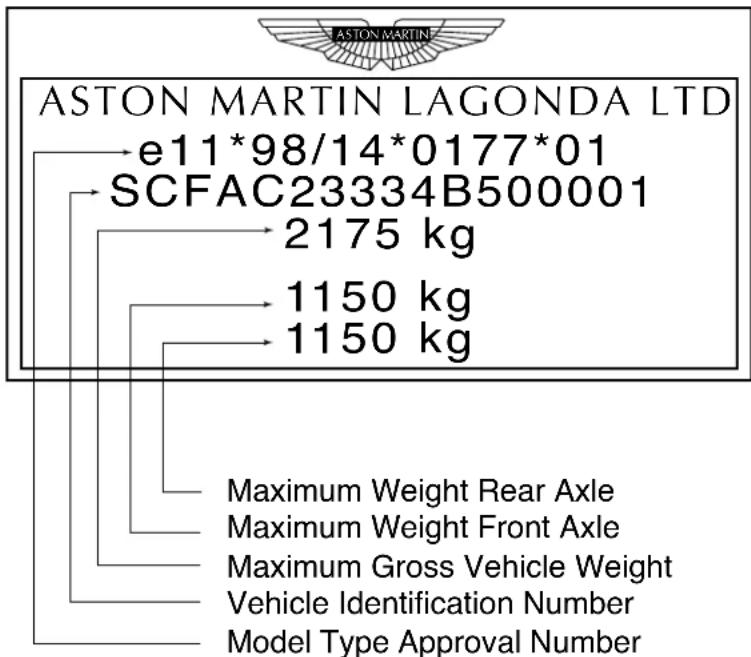
Vehicle Identification
The Vehicle Identification Number (VIN) is shown in the left hand corner of the windscreen and for USA is recorded as a barcode on the door pillar.

AIRBAG
X2
-SCFAC23334B500001-
ASTON MARTIN LAGONDA LIMITED
The Vehicle Identification Plate attached to the front crash structure is model and market dependant but typically contains the following types of information:
Reporting Safety Defects (USA)
If you believe that your vehicle has a defect which could cause a crash or could cause injury or death, you should immediately inform the National Highway Traffic Safety Administration (NHTSA) in addition to notifying Aston Martin Lagonda (North America) Inc. 533 MacArthur Boulevard, NJ 07430-2326.
If NHTSA receives similar complaints, it may open an investigation, and if it finds that a safety defect exists in a group of vehicles, it may order a recall and remedy campaign. However, NHTSA cannot become involved in individual problems between you, your Dealer, or Aston Martin Lagonda (North America) Inc.
To contact NHTSA, you may either call the Auto Safety Hotline toll-free at 1-800-424-9393 (or 366-0123 in Washington D.C. area) or write to: NHTSA, U.S. Department of Transportation, Washington D.C. 20590.
You can also obtain other information about motor vehicle safety from the Auto Safety Hotline.
Reporting Safety Defects (Other Markets - Non-USA)
If you believe that your vehicle has a safety defect which could cause a crash or could cause injury or death, you should immediately inform your Aston Martin Dealer or the manufacturers Service Operations Department at the address below:
Aston Martin Lagonda Limited, Service Operations Department,
Gaydon Engineering Centre, Banbury Road,
Gaydon, Warwick, CV35 0DB England
Telephone (International) ++44 1926 644700
(United Kingdom) 01926 644700
Facsimile (++44) 1926 644733
Regular Checks
In the interests of safety and reliability, it is advisable to carry out the following checks at the intervals suggested (more frequently if the vehicle is heavily used or operating in adverse conditions), and always before starting on a long journey. Refer to the Owner Maintenance section of this guide.
Each Day
Check that there is sufficient fuel for the intended journey, particularly at night and before entering highways.
Weekly - (Daily if covering high mileage or touring)
Tyres - Check the tyres for condition and pressure. See the 'Specifications' section for the recommended tyre pressures.
Lights - Check that all exterior lights and direction indicators function correctly and that the lenses are clean.
If a high mounted stop lamp bulb has failed, it must be replaced immediately to ensure that the correct lamp intensity is maintained.
Engine Oil - With the vehicle standing on level ground, check the oil level and top-up if necessary with oil of the correct grade.
Engine Cooling System - With the engine cold, check the level of the engine coolant. Top-up if necessary with coolant containing the required percentage of anti-freeze. Any significant coolant loss should be investigated by your Aston Martin Dealer.
Brake Fluid - Check the level of the fluid in the brake reservoir. Top-up if necessary with the specified brake fluid from a new unopened container.
Power Steering Fluid - Check and top-up the level of fluid in the power steering reservoir with fluid of the correct specification.
Monthly
Windscreen Washer - Top-up with the recommended windscreen wash fluid. Check the operation of the windscreen washers. Use the recommended concentration of additives to prevent freezing in winter conditions. Check the windscreen wash fluid level more frequently if the wash system is being heavily used.
Glossary of Terms
The following glossary contains frequently used alternative names or spellings for vehicle components mentioned in this Owner's Guide:
Bonnet Hood
Boot Trunk
Brake Disc Rotor
Handbrake Parking Brake
Petrol Gasoline
Tyre Tire
Wing Fender
Windscreen Windshield
Sill Rocker Panel
Data Recording
Computers in your vehicle are capable of recording detailed data potentially including but not limited to information such as:
• T he use of restraint systems including seat belts by the driver and passengers,
• Information about the performance of various systems and modules in the vehicle and
- Information relating to engine, throttle, steering, brake or other system status.
Any of this information could potentially include information regarding how the driver operates the vehicle, potentially including but not limited to information regarding vehicle speed, brake or accelerator application, or steering input. This information may be stored during regular operation or in a crash or near crash event.
This stored information may be read out and used by:
• Ford Motor Company
• Service and Repair Facilities
• Law Enforcement or Government Agencies
- Others who may assert a right or obtain your consent to know such information.
V12 Vanquish Owner's Guide
Contents
Vehicle Keys 1-A-2
Security of Keys and Key Fobs 1-A-2
Key Fob Time-Out 1-A-2
The Security System and Door Locks 1-A-3
Alarm Key Fob 1-A-3
Locking the Car / Turning on the Alarm 1-A-4
Unlocking the Car / Turning off the Alarm 1-A-4
Exit Illumination 1-A-5
Boot Release 1-A-5
Engine Immobiliser 1-A-5
Door Locks 1-A-5
Door Sealing 1-A-6
Interior Door Handles and Locks 1-A-6
Locking the Doors when Inside the Car 1-A-7
Drive-Away Locking 1-A-7
Adjustments Before Driving 1-A-7
Steering Wheel 1-A-8
Seat Controls 1-A-9
Interior Mirror 1-A-11
Door Mirror Switch 1-A-12
Seat Belts 1-A-13
Automatic Locking Retractors (ALR) 1-A-15
WARNINGS - Seat Belts - General 1-A-16
CHILDREN AND THE USE OF CHILD SAFETY SEATS 1-A-18
WARNINGS (USA / Australia): 1-A-20
Child Restraint Tether Anchorages (where fitted) 1-A-21
Wearing of Child Restraints 1-A-21
Correct Assembly of Tether Anchorages 1-A-22
Child Seat - Lower Anchorages (North America Only) 1-A-23
Airbags 1-A-25
Interior Storage 1-A-27
Boot Storage 1-A-28
A - Before Driving
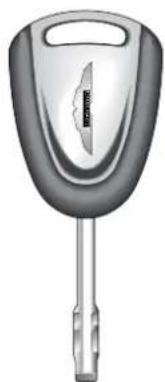
Vehicle Keys
Your Aston Martin Vanquish is supplied with two sets of keys. Each set contains the following:
• One ignition/door key.
- One alarm key fob
• One key number tag
natural_image
Exterior view of a car key with handle and spout (no text or symbols visible)
natural_image
Gray rectangular object with four control buttons and a small car icon, no visible text or symbols.Security of Keys and Key Fobs
Keep your key sets secure at all times. Remove the key number tags from each key set and keep them secure. The tag numbers will be required if you ever wish to obtain replacement keys.
Key Fob Time-Out
If the car is not used for 28 days, the key fob sensing circuits will switch off to conserve battery power. The doors may not then be opened with the key fob. Open either door with the ignition key to reactivate the sensor circuits, the key fob will then work normally.
The Security System and Door Locks
Your Aston Martin Vanquish is fitted with sophisticated security systems which protect your car against theft. The alarm system is linked to the central locking system. The following two pages describe the basic operations required to turn on or off the alarm and at the same time to lock or unlock the car. The systems are fully described in section 'F - Security Systems'.
Alarm Key Fob
Basic alarm functions are controlled using the alarm key fob which sends radio signals to the alarm unit aerial situated towards the rear of the car when any key fob button is pressed.

The upper left LOCK button is used for turning the alarm system on and locking the car.
The upper right UNLOCK button is used for turning the alarm system off and unlocking the car.

The lower left HEADLAMP button switches the head-lamps on for 25 seconds. Three presses on this button within 3 seconds will start the panic alarm.
The lower right BOOT button releases the boot.
The key fob has a range of about 10 metres (30 feet) when operating with no intervening obstructions.
Locking the Car / Turning on the Alarm

To turn the alarm system on and lock the car, stand within 10 metres (30 feet) of the car and point the key fob towards the rear window. Press the upper left button on the alarm key fob.
The car doors will be locked by the central locking system and the boot and fuel filler flap functions will be inhibited. The direction indicators will flash once (if programmed) as the alarm is switched on. Alarm sensing is then operative on the door locks, bonnet, boot and windows.
If the upper left button is pressed a second time within 3 seconds, the doors will be deadlocked (not USA).
WARNING: The deadlock function must not be used when persons or animals are inside the vehicle.
If the vehicle is locked (but not deadlocked) with a person inside, they may pull on either door handle to immediately release either door.
Unlocking the Car / Turning off the Alarm
To unlock the car and turn the alarm system off, approach to within 10 metres (30 feet) of the car and point the key fob towards the rear of the car. Press the upper right button on the alarm key fob.
The exterior direction indicators flash twice (if programmed), indicating that the alarm has been switched off.
As the vehicle is unlocked, the interior lights will also be switched on for 2 minutes or until 15 seconds after the doors are closed.
Exit Illumination

To illuminate the area around the car after parking, briefly press the lower left button once. The headlamps will come on for 25 seconds to light your way to or from the car.
Boot Release
The lower right button on the key fob provides an independent control for the boot lock even when the alarm is activated.
Press the lower right button once to release the boot lid. The alarm system will remain active on the remainder of the car if it was previously set.
When the boot lid is closed, it will self-lock and alarm sensing on the boot lid will be reactivated.
Engine Immobiliser
The engine is immobilised by a Passive Anti-Theft System (PATS) and may not be started until a correctly coded key is inserted and turned in the ignition switch (See 'Security Systems' for a full description of PATS). The PATS system is fully automatic and requires no intervention from the driver other than normal use of the ignition key.
Door Locks
Locking or unlocking of either door with the ignition key causes simultaneous locking or unlocking of the other door by means of the central locking system.
A - Before Driving
Door Sealing
Your Aston Martin V12 Vanquish is fitted with frameless door windows. A special door sealing system is fitted to ensure a tight fit of the door glass to the seals around the top of the door opening. This minimises wind noise and ensures a watertight window seal.
When you open a door, the window glass is automatically lowered a few millimetres to clear the door seal.
As you close a door, the window glass is automatically raised against the body frame rubber seals.
WARNING: Ensure that all occupants are clear when the window mechanism is operating.
Interior Door Handles and Locks
To open either car door from inside, pull on the release lever and push outwards on the door.
natural_image
Diagram of an airplane intake panel with control buttons and directional arrows (no text or labels)Warning: Doors cannot be opened using the interior handle if the vehicle is deadlocked.
Locking the Doors when Inside the Car
If you are sitting in the car with the ignition off and wish to lock the car doors from inside the vehicle, push outwards on the door handle. This will activate the central locking system and lock both doors. The boot opening will also be inhibited.
Pulling the door handle back to its central position will unlock the doors, fuel filler flap and boot.
Drive-Away Locking
During normal driving, the central locking system will automatically engage as you move off. Both doors and the boot will be locked. This function prevents forced access to the car when stopped at traffic lights etc.
Pull the door handle inboard to immediately release all locks when you wish to exit from the car.
Adjustments Before Driving
When you get into the car you should check and, if necessary, adjust the seat, steering wheel, interior and door mirrors, and secure your seat belt. The controls for these functions are described on the following pages.
A - Before Driving
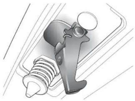
Steering Wheel
WARNING. Do not adjust the steering wheel whilst driving.
Rake
natural_image
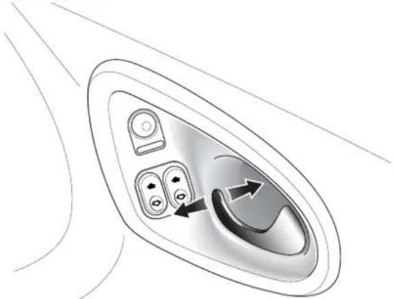
Medical illustration showing a hand operating a car wheel and a mechanical component inserted into the jaw (no text or labels)The rake of the steering wheel is adjusted by using the release lever to the lower left of the steering column.
Pull the release lever and apply downwards pressure on the steering wheel. Hold the wheel in the desired rake position and lock it by releasing the lever.
After locking, attempt to move the wheel up and down to ensure that the lock is fully engaged.
Reach
natural_image
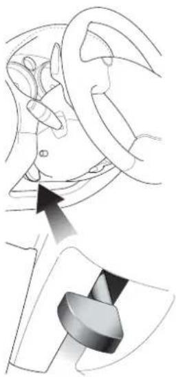
Medical illustration showing a hand holding a device with an arrow pointing to the ear area (no text or symbols present)The reach to the steering wheel may be adjusted by pushing down the lever below the steering column.
Adjust the reach position of the wheel and then raise the lever to lock the wheel position.
After locking, attempt to move the wheel in and out to ensure that the lock is fully engaged.
Seat Controls
Seat Tilt Lever
Raise the lever and tip the seat forwards to access the rear of the passenger compartment.
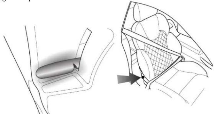
natural_image
Technical illustration of a car interior showing a vehicle seat and its side panel with mesh structure (no text or symbols)The Seat Control Switches
WARNING: Do not attempt to adjust the seat whilst driving.
Three rocker switches are mounted on the outside of each front seat. The switches may be operated with the ignition on or off.
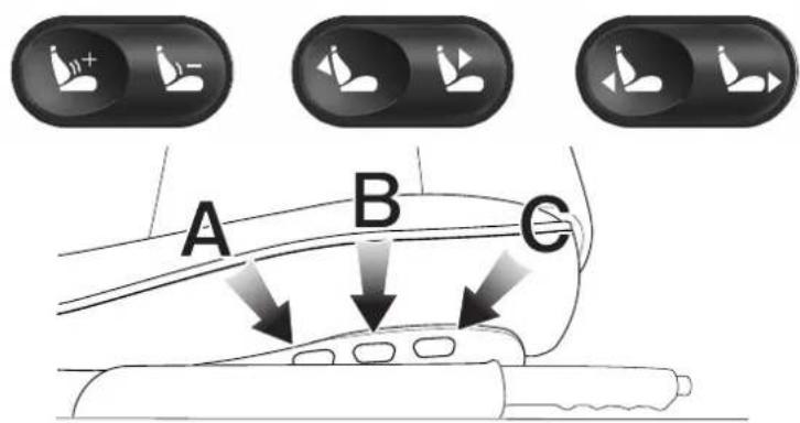
Lumbar Support - Press either the + or - symbol on the rear switch (A) to increase or reduce lumbar support.
B Seat Back Angle - Use the centre switch (B) to increase or decrease the angle of the seat back.
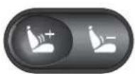
Front to Rear - Use the front switch (C) to move the seat in the forward or rearward direction.
Interior Mirror
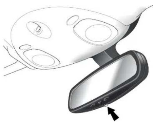
natural_image
Diagram of a car frontview mirror showing internal components and a directional arrow (no text or symbols)The interior rear view mirror is of the electrochromatic type. It is operated by the control button at the base of the mirror.
When switched on, the indicator lamp will be on and the rear view mirror will dim automatically if the glare from the headlights of following vehicles becomes too bright.
The mirror will return to normal view as unwanted glare reduces to an acceptable level.
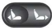
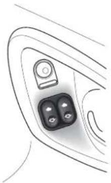
Door Mirror Switch
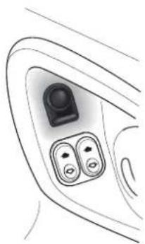
natural_image
Line drawing of a car interior showing two control buttons and a camera lens (no text or symbols)The exterior door mounted mirrors can be adjusted using a switch and joystick control mounted on the driver's door.
Note: The ignition must be switched on (position I or II) before the door mirrors can be adjusted.
To select the mirror to be adjusted, press the switch to select the right or left mirror.
The joystick can then be moved forwards and backwards or to the left and right to adjust the mirror up/down or left/right as required.
Power Fold Door Mirrors (Optional)
The optional 'Power Fold Mirror' function will rotate the door mirror assemblies until folded flat against the doors.
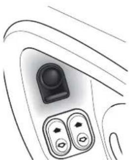
natural_image
Line drawing of a car interior showing the dashboard and air vent (no text or symbols)Set the mirror select switch in its central position and switch on the ignition. Press down and release the mirror adjust switch. The mirrors will motor to the 'fold back' position.
When the mirrors are required for driving, set the mirror select switch in its central position and switch on the ignition. Press down and release the mirror adjust switch. The mirrors will motor to the 'foldout' position.
The power fold mirrors are also photochromatic. They operate in conjunction with the photochromatic interior mirror.
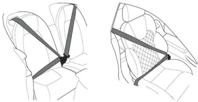
Seat Belts
natural_image
Two technical line drawings of car seatbelt configurations, showing front and side views (no text or symbols)The Aston Martin V12 Vanquish is fitted with two inertia reel seat belts (four belts on the 2+2 option). The inertia belt reels will automatically tension the belts to provide security with comfort. In the event of a collision or during severe braking, the belt reels will lock.
A light on the instrument panel is illuminated when the car is started if the driver's seat belt is not fastened. There is also a brief reminder buzzer that sounds at the same time.
Seat Belt Fastening
Sit upright with your back fully in contact with the seat back. Pull out the seat belt, drawing the tongue over the shoulder and across the chest.
Note: When parked on an incline, the belt may lock as it is withdrawn. This is not a fault. If the mechanism locks, release the belt tension and then pull the belt very gently to avoid operation of the inertia lock.
Push the tongue into the belt buckle latch until a positive click is heard.
A - Before Driving
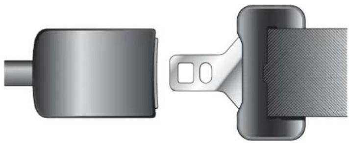
Seat Belt Fastening (continued)
natural_image
Technical illustration of a belt buckle and clasp (no text or symbols)Pull upwards on the diagonal belt to ensure secure latching and to remove all slack from the belt. Finally, double check that the lap belt is fitted snugly, low down across the hips, and that there are no twists.
If it is necessary for an occupant to adjust their seat or seating position during a journey, the belt tension might be disturbed. The occupant should therefore (as soon as it is safe to do so) gently pull down the shoulder run of the seat belt to create some slack and then immediately release it to re-tension the belt for the new seating position.
Seat Belt Pretensioner
The seat belt pretensioner system is designed to hold vehicle occupants against the seat back in the event of a frontal collision.
The seat belt pretensioner system works in conjunction with the airbag system. In a serious frontal impact, as the airbags are triggered, the pretensioners will also be simultaneously triggered. These apply additional tension to the front seat belts to hold the front seat occupants back in their seats.
Automatic Locking Retractors (ALR)
All vehicles are fitted with ALR seat belts in the front passenger seat and in the rear seats on the 2+2 option.
This system is designed to securely hold child seats. The ALR system temporarily locks the belt securing the child seat.
Securing a Child Seat (ALR System)
Fit the child seat following the manufacturers instructions. Gently pull out the relevant inertia reel seat belt until fully extended. The ALR system will only engage at the maximum extension point of the seat belt.
Thread the belt tongue through the child seat as instructed by the child seat manufacturer. Engage the tongue into the belt buckle. Adjust the tongue position on the belt if necessary to ensure that the lower belt run is tight and then allow the upper run of the seat belt to fully retract until the child seat is securely held. The ALR system will be heard 'clicking' as the seat belt retracts. When fully retracted, pull down on the upper run of the belt to check that the ALR lock has engaged.
Child Seat Removal (ALR System)
To remove the child seat, release the belt as normal and allow it to retract through the seat frame. The ALR system will disengage when the belt is fully retracted. The belt may then be worn when required as a normal inertia reel belt. Once the ALR is disengaged, the belt must be fully extended to re-engage the system on the next occasion that a child seat is fitted.
WARNINGS - Seat Belts - General
Wearing your seat belt is crucial to your safety. Not wearing a seat belt increases the chance of serious injury or death in the event of an accident. Be sure that you and your passengers always fasten their seat belts and use them properly even though airbags are provided. Seat belt usage is mandatory in most countries and should be used in accordance with local laws.
By reclining the seat back, you decrease the protection you get from the seat belt in the event of a crash. Adjust the seat back to an upright position (approximately 90^ to the seat base).
Make sure that the seat back is locked in place. Otherwise it could move forward in a sudden stop or crash and cause injury.
Seat Belts are designed to bear upon the bone structure of the body and should be worn low across the front of the pelvis and across the chest and shoulders. Wearing the lap portion of the belt across the abdominal area must be avoided. Never place the shoulder portion of the belt under your arm or behind your back.
Always remove from your pockets rigid or breakable objects, such as spectacles, which could be trapped under seat belts, possibly causing injury in the event of an accident.
Expectant mothers should seek medical advice on the most appropriate way to wear the seat belt.
In the interests of safety, seat belts must be kept clean so that the retractor works correctly. Ensure that the belt webbing is not twisted, looped, frayed or obstructed in any way. If in doubt about the condition or operation of the seat belt installation, have it checked by your Aston Martin Dealer.
No modifications or additions should be made by the user which will either prevent the seat belt adjusting devices from operating, or prevent the seat belt assembly from being adjusted to remove slack. Never install accessories on your seat belts.
SPECIAL WARNINGS ON USE OF CHILD SAFETY RESTRAINTS:
A child, regardless of age, should always be restrained when travelling in a vehicle. The following precautions are strongly recommended.
Do not allow children to travel in the vehicle without restraint. Approved child seats or harnesses should always be used.
Each seat belt assembly must be used by only one occupant. It is dangerous to put a seat belt around a child being carried on the occupants lap.
Accident statistics show that children are generally safer when properly restrained in the rear seat than in the front seat. A suitable child restraint, properly installed and used, provides the highest degree of protection for infants and small children in most accident situations.
Child restraint anchorages are designed to withstand only those loads imposed by correctly fitted child restraints. Under no circumstances are they to be used for adult seat belts, harnesses or for attaching other items or equipment to the vehicle.
Do not use a rearward facing child restraint on a seat protected by an airbag in front of it.
CHILDREN AND THE USE OF CHILD SAFETY SEATS
An infant or child that is not properly restrained can be seriously injured or killed in a crash. Seat belts are designed for adults and larger children; infants and smaller children must be restrained in an approved child safety seat.
All child restraint systems are designed to be secured by lap belts, or the lap belt portion of a lap-shoulder belt. Children could be endangered in a crash if their child restraints are not properly secured in the vehicle. If you choose to use a child safety seat, follow the manufacturers instructions. Never hold a baby or child on your lap while riding in the car.
For use in USA, the child safety seat must be in conformity with Federal Motor Vehicle Safety Standard 213. Look for the statement on the box and seat.
Check the seat manufacturers instructions for proper use and installation - use the correct size seat and properly secure the seat in the car in accordance with the manufacturers instructions. Be sure to read and follow the 'Installation and Use Instructions' provided with the child seat.
Remember that children who have outgrown child restraints should wear the vehicle's seat belt.
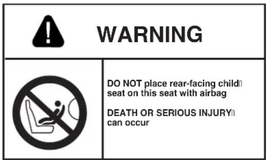
CHILD SEATS AND PASSENGER AIRBAGS
DO NOT install a rearward facing child seat in the front passenger seat position.
If a child seat is required, Aston Martin strongly recommend a forward facing child seat fitted securely to one of the rear seats (if fitted). If a front seat position must be employed, use only a forward facing child seat with the passenger seat set as far rearwards as practical.
CHILD SAFETY RESTRAINTS - 2+0 VEHICLES ONLY
WARNINGS:
Never carry a rearward facing child seat in this vehicle.
Aston Martin recommend not to place any child seat in this vehicle.
If you choose to place a forward facing child seat in this vehicle, use the upper tether kit provided to secure the child restraint in the front passenger seat and move the passenger seat to its rearmost position.
WARNINGS (USA / Australia):
Seat belts are designed to bear upon the bony structure of the body, and should be worn low across the front of the pelvis or the pelvis, chest and shoulders, as applicable; wearing the lap section of the belt across the abdominal area must be avoided.
Seat belts should be adjusted as firmly as possible, consistent with comfort, to provide the protection for which they have been designed. A slack belt will greatly reduce the protection afforded to the wearer.
Care should be taken to avoid contamination of the webbing with polishes, oils and chemicals, and particularly with battery acid. Cleaning may safely be carried out using mild soap and water. The belt should be replaced if webbing becomes frayed, contaminated or damaged.
It is essential to replace the entire assembly after it has been worn in a severe impact even if damage to the assembly is not obvious.
Belts should not be worn with straps twisted.
Each belt assembly must only be used by one occupant; it is dangerous to put a belt around a child being carried on the occupants lap. Do not put an adult seat belt around two children.
No modifications or additions should be made by the user which will either prevent the seat belt adjusting devices from operating to remove slack, or prevent the seat belt assembly from being adjusted to remove slack.
When installed, the seat belt webbing must not contact any sharp edges which could abrade or cut the webbing during normal use or in an accident. If necessary, the webbing must be protected.
Child restraint anchorages are designed to withstand only those loads imposed by correctly fitted child restraints. Under no circumstances are they to be used for adult seat belts, harnesses or for attaching other items or equipment to the vehicle.
Child Restraint Tether Anchorages (where fitted)
Note: Identical anchorage points are fitted for some other countries.
USA and Australian regulations require that a child restraint anchorage be fitted for each rear seating position on the 2+2 option.
The anchorages provided are threaded fasteners located in the rear parcel shelf on the centre-line of each rear seating position. Anchorage point thread form is 5/16 inch - 18 UNC. (see diagram on following page)
Look for the following when selecting a child restraint system:
It should have a label certifying that it meets the applicable Motor Vehicle Safety Standards.
Carefully read the instructions supplied with the restraint. Be sure you understand them and can install and use the device properly and safely in the vehicle.
Ensure that the child restraint system is appropriate for the child's weight and development. The label required by the standard or regulations, or instructions for infant restraints, usually provide this information.
Wearing of Child Restraints
Ensure that there is no slack in the webbing and that the restraint fits the child snugly across the rib cage and hips. These are the parts of the body most able to take the force of impact.
The lap strap should pass across the top of the child's thighs, bearing on the pelvis, not on the abdominal area.
A - Before Driving
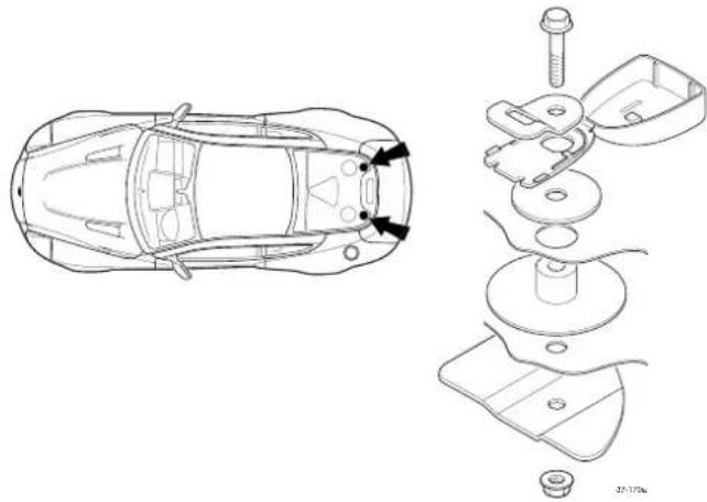
Correct Assembly of Tether Anchorages
The following diagram indicates the correct fitting of the child seat attachment clip to the anchor fitting.
Engage the attachment clip in the orientation shown and ensure that the locking spring has fully closed to prevent accidental disengagement of the upper tether strap.
Always ensure that the upper tether strap length is adjusted to remove any slack.
natural_image
Technical line drawing of a car showing top-down and exploded views (no text or symbols)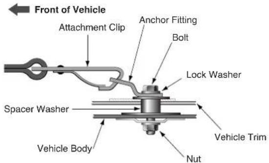
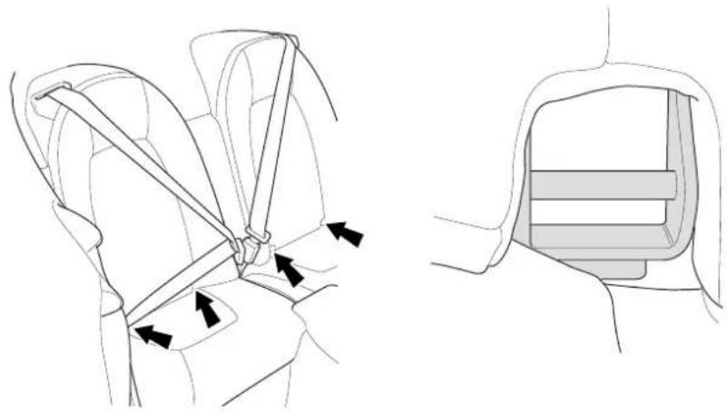
Child Seat - Lower Anchorages (North America Only)
From September 2002, child seats sold in North America must be fitted with two lower anchors which will latch to lower anchorages at the base of either rear seat (anchorage positions are arrowed on the diagram below).
natural_image
Technical line drawing showing car seatbelt buckle assembly (no text or symbols)Warning: Check the seat manufacturers instructions for proper use and installation - use the correct size seat and properly secure the seat in the car in accordance with the manufacturers instructions. Be sure to read and follow the 'Installation and Use Instructions' provided with the child seat.
Follow the seat manufacturers instructions to latch such a child seat to the cars lower anchorages. After fitting the child seat, pull forward firmly on each side of the seat to ensure that both latches are correctly engaged. Also follow the seat manufacturers instructions to correctly secure the child into the child seat.
Warning: An infant or child that is not properly restrained can be seriously injured or killed in a crash. Seat belts are designed for adults and larger children; infants and smaller children must be restrained in an approved child safety seat.
USE OF CHILD SEATS IN THE EUROPEAN COMMUNITY
WARNING
Child Restraints
Aston Martin has not tested any child restraint systems for this vehicle, and does not recommend any specific child restraint system.
The following table is supplied under EC Directive 77/541.
| Mass Group Seating Position | ||
| as indicated on the child safety seat packaging | Front Passenger | Second Row Outboard |
| 0 = Up to 10kg (0-9 months) X X | ||
| 0+ = Up to 13kg (0-18 months) X X | ||
| 1 = 9 to 18kg (9 months to 4 years X X | ||
| 11 & 111 = 15 to 36kg (4 to 12 years) | X | X |
| U = Suitable for “universal” category restraints approved for this mass group. | ||
| X = Seat position not suitable for children in the mass group. | ||
| * = Unsuitable for use with many child restraints due to limited space. | ||
Please consult with local manufacturers of smaller forward facing restraint and booster cushions. These manufacturers can supply you with advice on the safety of their particular child restraints, the position that they recommend, and also advice on fitting instructions.
Do not seat a child aged 12, or younger. or weighing 36 kg or less in the car without an appropriate child seat or booster cushion. Please confirm that any child seat or booster cushion you may fit in the vehicle has been designed for use in this model, and that it conforms to local market requirements.
Airbags
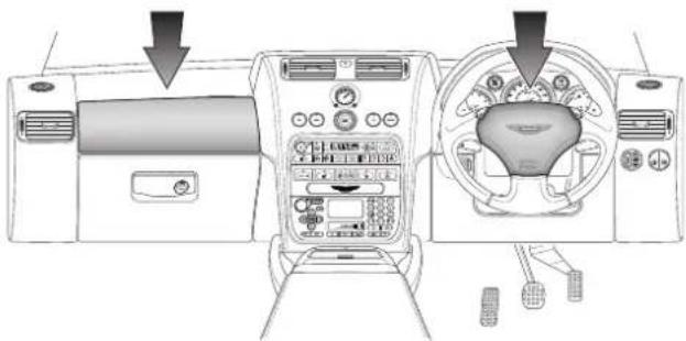
natural_image
Interior view of a car dashboard and steering wheel (no text or symbols visible)In order to provide optimum occupant protection, Aston Martin V12 Vanquish is equipped with driver and passenger airbags. The driver's airbag is mounted in the centre of the steering wheel. The front passenger airbag is located in the facia panel immediately in front of the passenger seat. The airbags are supplementary to the seat belts.
Note: There are important airbag safety labels on the sun visors (illustrated below).
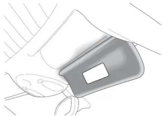
natural_image
Line drawing of a car seatbelt with handle and seatbelt (no text or symbols)Some models may have additional safety labels elsewhere, easily visible to the vehicle occupants. Ensure that you have read and complied with the instructions on these labels prior to driving the vehicle.
A - Before Driving
Do not change or modify or tamper with the steering wheel, passenger side fascia or any other part of the airbag system. Such actions could disable the system or cause inadvertent inflation.
The airbags are designed to deploy only in a serious frontal collision. Their purpose is to provide additional protection for the front seat occupants if thrown forwards in an accident. The system is designed so that it will not deploy in the event of trivial frontal impacts such as minor contacts when parking. The airbag system is not designed to protect against side or rear impacts.
WARNINGS:
No objects whatsoever should be attached to the centre cover of the steering wheel or the passenger fascia panel. Such objects could cause harm if the vehicle is in a crash severe enough to cause the airbags to deploy.
All occupants, including the driver, should always wear seat belts, whether or not an airbag is provided, to decrease the risk of injury or death in the event of a crash.
Any work on the airbag system must only be carried out by an Aston Martin Dealer.
CHILD SEATS AND PASSENGER AIRBAGS
DO NOT install a rearward facing child seat in the front passenger seat position. If a child seat is required, Aston Martin strongly recommend a forward facing child seat fitted securely to one of the rear seats (where fitted). If a front seat position must be employed (e.g. in a 2 + 0 car), use only a forward facing child seat with the passenger seat set as far rearwards as practical.
Interior Storage
Covered storage compartments are provided between the front and rear seats. A lockable glove box is located in the passenger side facia and storage pockets are provided in the doors.
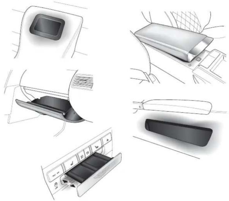
natural_image
Illustration of car seatbelt components including door, seatbelt cover, and air conditioner panel (no text or symbols)A coin tray is located in the centre console. press the tray front panel to open it. To close the tray, push in until it latches
A - Before Driving
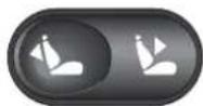
Boot Storage
The Owners Guide is stored in a net pocket mounted in the roof of the boot compartment.
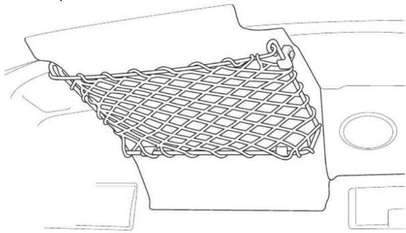
natural_image
Line drawing of a mesh net inside a vehicle's seat frame (no text or symbols)Contents
Instruments 1-B-2
Tachometer 1-B-2
Speedometer 1-B-2
Fuel Gauge 1-B-2
Engine Coolant Temperature Gauge 1-B-3
Message Display 1-B-3
Trip Computer 1-B-4
The Trip Switchpack 1-B-5
Resetting the Trip Computer 1-B-5
Warning Messages 1-B-6
Information/Warning Lights 1-B-7
Information/Warning Lights 1-B-8
Instrument Panel Illumination 1-B-11
Tyre Pressure Sensing 1-B-12
Summary of Tyre Pressure Warning Indications 1-B-14
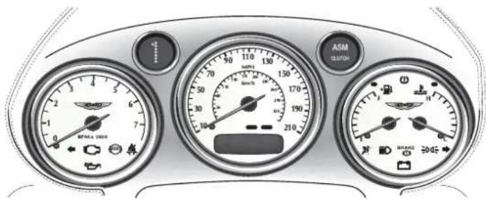
Instruments
Your Aston Martin Vanquish has been designed to provide easy access to all necessary vehicle information. The illustration below shows the main information sources on the instrument panel and centre console.
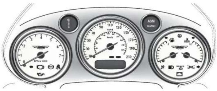
Tachometer
Indicates the engine speed in revolutions per minute x 1000.
Speedometer
Indicates the vehicle road speed in miles per hour and/or kilometres per hour. It also houses the message display.
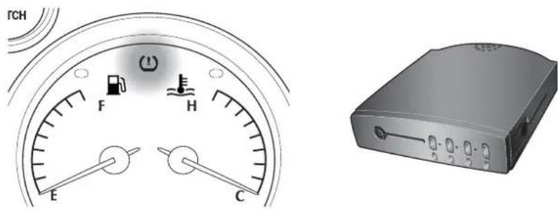
Fuel Gauge
The fuel capacity is 80 litres (17.6 Imp gallons / 22 US gallons). The Low Fuel warning lamp will illuminate when approximately 16 litres (3.5 Imp Gallons / 4.4 US Gallons) remain.
Note: Only about 11 litres (2.5 Imp Gallons/3.0 US gallons) of the reserve may be used. This gives sufficient fuel for approximately 80 kilometres (50 miles) of normal motoring.
Engine Coolant Temperature Gauge
Normal coolant temperature is indicated with the needle near the centre of the gauge, but coolant temperature will normally vary (within the range 92 - 105°C) dependent on ambient temperature and driving conditions.
Message Display
The liquid crystal display in the base of the speedometer shows the odometer and trip meter readings. It is also used to display status messages when necessary.
Odometer
Shows the total distance covered by the vehicle.
Trip Meter
Shows the distances travelled since the last reset of trip computer counters A and B. (See the full trip computer description on the following page.)
Trip Computer
The trip computer display is controlled using the trip function button on the end of the left stalk.
natural_image
Gray handheld device with directional arrows and icons, no visible text or symbolsRepeated pressing of the trip function button will cycle through the following displays:
Odometer - Total distance travelled by the vehicle (no reset).
Trip Distance A or B - Distance since the last reset of trip counter A or B.
Range - Estimated range on the remaining fuel (no reset).
Fuel Used - Total fuel used since the last reset.
Average Fuel - Average fuel consumption since the last reset.
Instantaneous Fuel - Consumption over the last 3 seconds (no reset).
Average Speed - Average speed since the last memory reset.
Pressing the trip function button again when the average speed is displayed will return to the Odometer display.
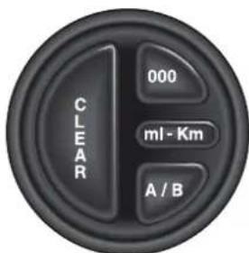
The Trip Switchpack
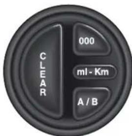
The trip computer display mode and the reset function are controlled using the trip switchpack on the end of the facia.
CLEAR - Clears current warning messages from the display for 10 seconds to temporarily display odometer/trip data.
Press the clear button repeatedly to cycle through Trip - Odometer - Message displays.
000 - Sets the selected trip to zero.
A/B - Toggles between trip memories A and B.
ml-km - Selects imperial or metric display units.
Resetting the Trip Computer
Press the trip function button on the left stalk to display the required parameter. Use the A/B button if necessary to select the A or B counter.
Press the 000 button for more than 3 seconds to reset the selected parameter.
Note: The Odometer, Range and Instantaneous Fuel Consumption parameters cannot be reset.
Warning Messages
Important systems and components of the car are regularly monitored. A warning message will appear in the message display if an unsatisfactory condition is detected. Message priority is indicated by the red or amber indicators above the message display.
Red - Potential personal danger or danger of damage to the vehicle.
Amber - Advisory, indicate possible degraded vehicle performance.
Warning messages will always have priority over trip data and, if active, will always be displayed when the ignition is on.
| Message Priority Meaning | ||
| Bonnet Open Red Close | bonnet securely | |
| Boot Open Red Close boot securely | ||
| Check Rear Lights Amber | Rear bulb failure | |
| Driver Door Open Red | Correctly close drivers door. | |
| Electrical Fault Amber | Fault in control circuits | |
| Engine Coolant Low. | Red Coolant level below minimum | |
| Engine Stalled Red Engine speed below 10 | rpm. | |
| Gearbox Fault Amber | Temporary/Permanent gearbox fault | |
| Handbrake On Red Check handbrake fully | Off | |
| High Gearbox Temp Amber | Possible gearbox cooling fault | |
| Passenger Door Open Red | Correctly close | passenger door. |
| System Check | Red/Amber | Normal self check at ignition On |
| Traction Control Fail | Amber | Report to an AML Dealer. |
| Washer Fluid Low | Amber Top up as necessary | |
Information/Warning Lights
The Instrument Panel contains a number of information and warning lights. The information/warning light colours are significant and have the following uses:
RED is used to warn drivers of concerns which may endanger them (e.g. Seat Belt Warning, Brake System Warning, etc.) or to indicate potentially serious problems with the car (e.g. Low Oil Pressure)
AMBER is used for non-emergency indications such as Low Fuel.
GREEN signals the use of normal functions such as Direction Indicators.
BLUE is used to indicate that the Headlight Main Beams are on.
The following descriptions cover all instrument panel warning lights grouped in the order; warnings (reds), cautions (ambers), and normal status lights (greens and blue).
Information/Warning Lights
Ignition Warning Light (Red)
Illuminates when the ignition is switched on. Extinguishes when the engine is started and battery charging commences.
Will illuminate if battery charging fails whilst driving.
Brake Warning (Red)
BRAKE

Illuminates when the brake fluid level is low. May illuminate with the ABS Warning Light.
Note: When the ignition is turned on, the Brake warning light will illuminate briefly and extinguish if the brake fluid level is within specification.
BRAKE

Parking Brake Warning (Red)
The brake warning lamp also illuminates when the parking brake is applied with the ignition On.
Oil Pressure Warning Light (Red)

Illuminates when the engine oil pressure falls below minimum. Do not continue driving if this light remains illuminated. Consult your Dealer immediately.

Seat Belt Warning (Red)
This warning lamp will illuminate and a chime will sound if the driver's seat belt is not fastened when the ignition is switched on.
ABS Warning Lamp (Amber)
Indicates a concern in the ABS control circuits. Consult your Dealer immediately if this light remains illuminated.
Low Fuel Warning Lamp (Amber)
The Low Fuel warning lamp will illuminate when approximately 16 litres (3.5 Imp Gallons / 4.4 US Gallons) remain.
Check Engine (Amber)
Indicates that an anomaly is detected in the engine management system. The vehicle may go into 'Limp Home' mode with the possibility of reduced engine performance.
If the lamp is on constantly, complete your journey and consult your dealer at the earliest opportunity.
If the lamp flashes, a misfire is occurring which could damage the catalytic convertor. Stop as soon as possible in a safe location and have your car recovered to an Aston Martin Dealership.

SRS (Supplementary Restraint System) (Amber)
Flashes if a fault is detected in the airbag system.
When you start the car, this lamp comes on for a few seconds as a readiness indicator. If it does not come on when you start the car, or if it does not go off after a few seconds, or if it comes on whilst driving, the airbag self-diagnostic system has detected a fault. In such cases, take your vehicle immediately to an Aston Martin Dealer for inspection.
B - Driver Information

Left Turn Direction Indicator (Green)
Flashes with the indicator lights during operation of the left turn signal or hazard warning lights.

Right Turn Direction Indicator (Green)
Flashes with the indicator lights during operation of the right turn signal or the hazard warning lights.

Headlights (Blue)
Shows when the main beams of the headlights are in use.

Side lamps (Green)
Indicates when the side lamps are illuminated
High Coolant Temp
Indicates when engine coolant temperature exceeds 120°C

Low Tyre Pressure
Illuminates when tyre pressure falls below specification.
Flashes if a tyre pressure is dangerously low.
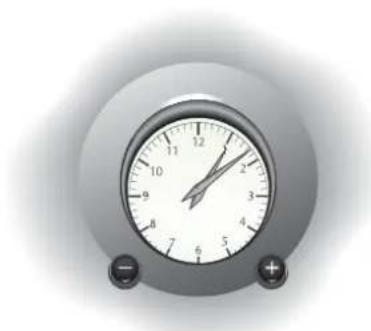
Clock
natural_image
Close-up of a analog alarm clock with dual dials and buttons (no visible text or numbers)The clock in the centre of the fascia is set using the buttons on the clock panel. The left button is used to retard the time and the right button to advance the time.
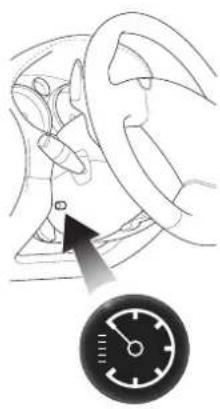
Instrument Panel Illumination
natural_image
Diagram of a car wheel and steering wheel with a speedometer (no text or symbols)The level of instrument illumination can be adjusted using the rotary control on the left hand side of the steering column.
Clockwise rotation increases the brightness of the illumination.
Tyre Pressure Sensing
The tyre pressure sensing system operates to remotely monitor tyre pressures and feed back information on tyre pressures to the driver.
Warning: This system is not intended to replace normal driver awareness of tyre performance or the need for the recommended weekly checks on tyre condition and pressure.
Each wheel is fitted with a tyre pressure sensing device which sends tyre pressure information to a control box mounted on the right hand side of the boot.
The control box will give the driver a visual warning by illuminating the tyre pressure warning lamp in the instrument panel if any tyre pressure falls below specification.
The Tyre Pressure Warning Lamp
When the tire pressure monitoring system warning light is lit, one or more of your tyres is significantly under-inflated. You should stop and check your tyres as soon as possible, and inflate them to the proper pressure as indicated on the vehicle's tyre information placard. Driving on a significantly under-inflated tyre causes the tyre to overheat and can lead to tyre failure. Under-inflation also reduces fuel efficiency and tyre tread life, and may affect the vehicle's handling and stopping ability. Each tyre, including the spare, should be checked monthly when cold and set to the recommended inflation pressure as specified in the vehicle placard and owner's manual.

The warning lamp has two levels of illumination.
Lamp on Permanently - Tyre pressure below specification. Reduce speed immediately to 30 mph and re-inflate the tyre at the first possible opportunity.
Lamp Flashing - Tyre pressure dangerously low. Stop immediately in a safe location. Check for a puncture and repair if possible using the procedure in 'Owner Maintenance'. If not, call for assistance.
One of the coloured lamps on the right side of the control box will also illuminate red to indicate which tyre requires inflating. The lamp colour corresponds to the colour of the band below each tyre valve cap. Take care to replace caps on the correct wheel after re-inflating tyres.
If the left hand control unit lamp illuminates amber, there is a control unit fault. Consult your Aston Martin dealer.
Summary of Tyre Pressure Warning Indications
| Instrument Pack Warning Lamp | Tyre Pressure Module | Fault | Recommended Action |
| Flashing Warning | Tyre LED flashing Red | Tyre below lower pressure threshold | Stop in safe place ASAP Seek assistance or refer to tyre inflation section of Owners Guide |
| Constant Warning | Tyre LED constant Red | Tyre below upper pressure threshold | Max Speed 30 mph Inflate to specified pressure at earliest opportunity |
| Constant Warning | Tyre LED constant Amber | Tyre Transmitter Fault | Stop in safe place ASAP Inspect affected tyre for flat. Reinflate if necessary. If OK, continue at 30 mph maximum and have transmitter replaced at earliest opportunity. |
| Constant Warning | Module LED Constant Amber | Receiver Module Fault | Check all tyre for flats. If OK, continue at 30 mph maximum. Have receiver replaced at earliest opportunity |
Pressure Sensing with Winter Wheels and Tyres
Tyre pressure sensing does not function when winter wheels and tyres are fitted. The indicator lamps in the pressure sensing unit will all remain illuminated. The instrument panel warning lamp will remain extinguished. Tyre pressure sensing will be reinstated when the normal wheels with pressure sensors are refitted.
Contents
Steering Column Controls - Left Hand Stalk 1-C-3
Turn Signals 1-C-3
Side and Headlight Switching 1-C-4
Main and Dipped Beam Switching 1-C-4
Headlight Flashing 1-C-4
Automatic Headlamp Switching 1-C-5
Steering Column Controls - Right Hand Stalk 1-C-7
Windscreen Wiper Control 1-C-7
Windscreen Wiper Delay Control 1-C-8
Automatic Screen Wiping 1-C-8
Windscreen Washer Control 1-C-9
Steering Wheel Horn Push 1-C-9
Console Mounted Controls 1-C-10
Supplementary Switches 1-C-12
Fuel Flap and Boot Release Switches 1-C-14
Fuel Flap Switch 1-C-14
Boot (Trunk) Release Switch 1-C-14
Cigar Lighter and Ashtray (Optional) 1-C-16
Accessory Sockets 1-C-17
Bonnet (Hood) and Boot (Trunk) 1-C-18
Bonnet (Hood) Release 1-C-18
Bonnet (Hood) Safety Catch 1-C-18
Closing the Bonnet (Hood) 1-C-18
Electric Window Switches 1-C-19
Electric Window 'One Touch Down' Feature 1-C-19
Interior Lights 1-C-20
HomeLink Universal Transceiver (Optional) 1-C-21
Programming 1-C-22
Rolling Code Programming 1-C-23
Operation 1-C-23
Reprogramming a HomeLink Button 1-C-24
Erasing Programmed HomeLink Buttons 1-C-24
C - Controls
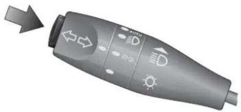
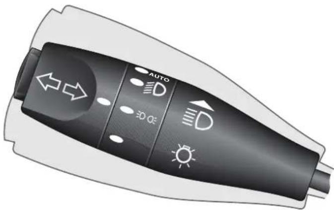
Steering Column Controls - Left Hand Stalk
natural_image
Illustration of a handheld electric shocker with directional and weather icons (no text or symbols)The left column stalk controls the following functions:
Turn Signals
Move the stalk up to indicate a right turn, or down to indicate a left turn. The stalk automatically returns to the centre position on completion of the manoeuvre. The stalk may be moved partially up or down to bring on the indicator lights to indicate a lane change. When released from the partially up or down positions, the stalk is returned to the centre position by spring pressure.
If an external indicator bulb fails, the remaining indicator lights on that side of the car and the instrument panel warning light for that side will flash at twice the normal rate when a turn to that side is indicated. If this situation occurs, replace the defective bulb as soon as possible.
Side and Headlight Switching
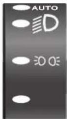
The left stalk collar has four positions that control the external running lights of the vehicle:
In the off position all external lights are off.
Rotating the collar to the first click (the side lamp symbol) switches on the side lights, side marker lights, rear lights and registration plate lights (licence plate lights).
Rotating to the second click position (the headlamp symbol) switches on the headlight dipped beams in addition to the side, side marker, rear and registration plate (licence plate) lights.
Rotating the control to the AUTO position activates the automatic headlamp switching function. (see Automatic Headlamp Switching)
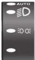
Main and Dipped Beam Switching
When the headlight dipped beams are switched on, they may be switched to main beams by pushing the left stalk forward, away from the steering wheel. Pulling the left stalk back to its central position will switch the headlights back to dipped beams.
Headlight Flashing
When all lights are off or when only the side lights and dipped beams are on, the headlight main beams may be flashed by pulling the left stalk towards the steering wheel. The headlights will return to their previous state when the stalk is released.
Automatic Headlamp Switching
When this function is switched on and when external light fades to a predetermined level, the side lights and headlamps will automatically switch on after a short delay.
The ignition switch must be in position 'II' and 'Auto' must be selected on the left hand stalk to activate automatic exterior light switching.
Operation
With the ignition on, turn the exterior lighting control to AUTO. A sensor on the back of the interior mirror will monitor exterior light levels and automatically switch on the sidelights and dipped headlamps when necessary.
The side light warning lamp will also illuminate as the exterior lights are automatically switched on.
As the exterior light level increases above the predetermined threshold, the sidelights, headlamps and warning lamp, switch off after a short delay.
C - Controls
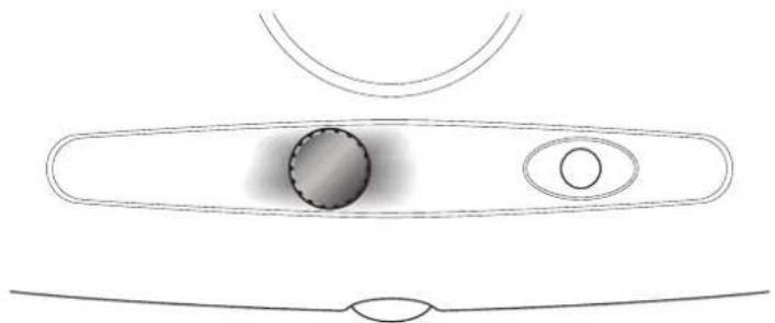
Sensitivity Adjustment
natural_image
Simple line drawing of a biological structure with oval shapes and internal features (no text or symbols)The sensitivity of the auto headlamp switching system can be adjusted by turning the sensor control knob on the back of the interior mirror, anticlockwise to decrease or clockwise to increase sensitivity.
Do not cover the sensor. Keep the windscreen clean. Obstructing the light in this area may lead to unwanted operation of the sidelights and headlamps when the switch is set to AUTO.
We recommend that the rotary collar on the column switch gear is left in the AUTO position at all times as a convenience feature.
Caution: If the AUTO function fails, rotate the collar manually to control the vehicle running lamps as necessary.
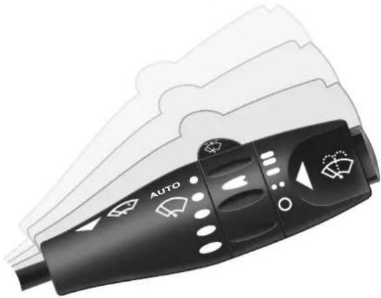
Steering Column Controls - Right Hand Stalk
natural_image
Close-up of a black automotive air conditioner with white indicator lights and 'AUTO' label (no readable text beyond branding)The right column stalk controls the following functions:
Windscreen Wiper Control
Upwards movement of the stalk from its lowest position switches the wipers through the range, Off - Intermittent Wipe - Normal Speed Wipe - Fast Wipe.
C - Controls
Windscreen Wiper Delay Control
When in the intermittent wipe position, the wiper delay interval may be adjusted using the collar on the right stalk. The wiper delay increases by two seconds for each of the four collar positions. Rotation of the collar to the forth position away from the driver gives the shortest delay between wipes.
The fifth 'AUTO' position activates the automatic rain sensor and wind-screen wipe function if intermittent wipe is selected.
Automatic Screen Wiping
When the AUTO position is selected on the intermittent wipe collar, the wipers will operate to clear the screen whenever rain or other moisture is detected.
CAUTION: Ensure that AUTO is not selected when entering a car wash as damage to the wiper blades/arms can occur.
Windscreen Washer Control
The windscreen washers are switched on by pressing the button on the end of the right column stalk. The washers and wipers continue operation whilst the button is pressed. On releasing the button, the washers stop immediately but the wipers continue for a few strokes to clear any residual washer fluid from the screen.
If the washer button is used during normal wiper operation, the washers operate whilst the button is pressed and the wipers operate continually irrespective of the washer operation.
The washer will become inoperative when the washer bottle is empty.
Steering Wheel Horn Push
The horn push buttons are incorporated into the centre pad of the steering wheel. The horn is sounded by pressing either button.
Console Mounted Controls
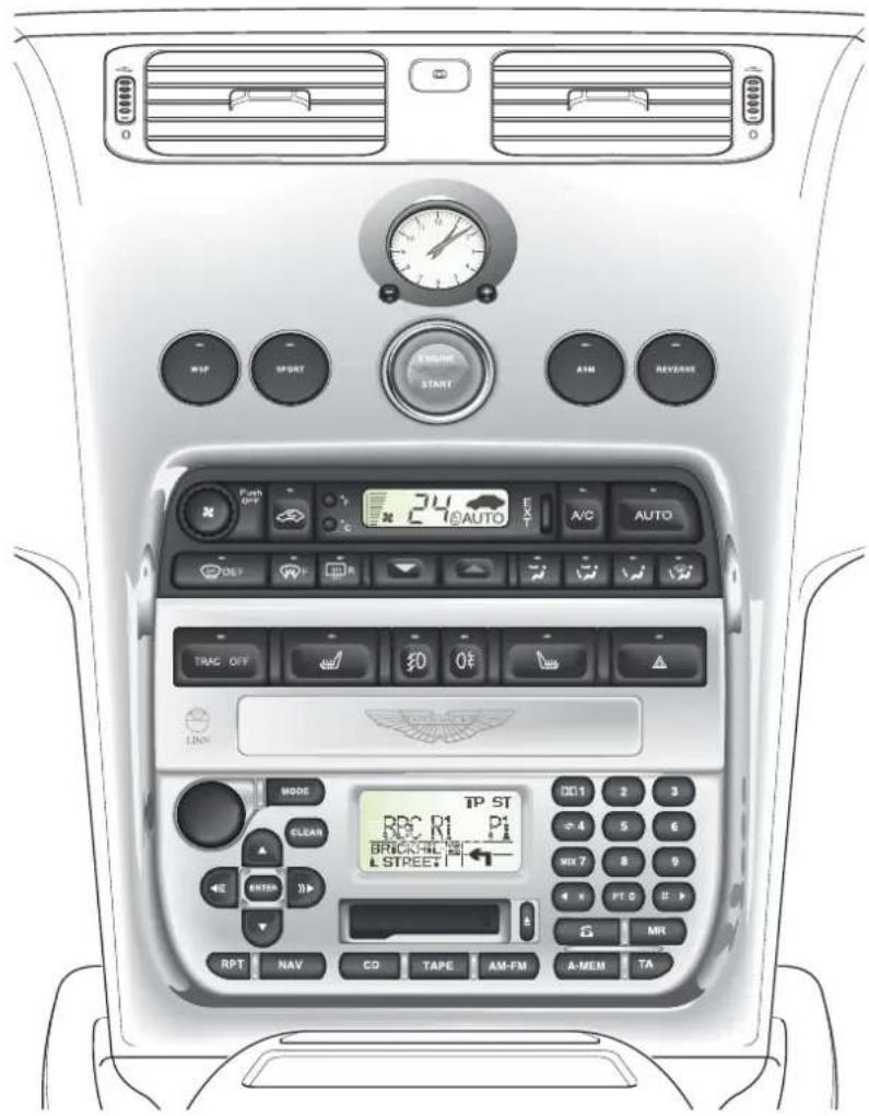
The centre console contains the following controls:
- Transmission Control Switches
- Starter Button
• Heating, Ventilation and Air-Conditioning Controls
• Supplementary Switches
• Radio Cassette Player/Satellite Navigation Unit
• Cigar Lighter and Ashtray/Coin Tray, Accessory Socket
The transmission control switches are described in the 'Driving' section of this Owner's Guide.
The Heating, Ventilation and Air-Conditioning Systems are fully described in the Air-Conditioning section.
C - Controls
Supplementary Switches
The row of switches mounted beneath the air-conditioning panel will vary dependant on market. Your V12 Vanquish will have an appropriate selection of the switches described below.
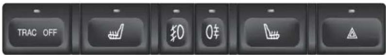
As any switch is actuated, a warning lamp within the switch will illuminate to indicate that the selected function is on.
Front Fog Lights
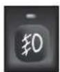
The front fog lights can be switched on when the headlights or sidelights are in use. They must be switched off when visibility clears to reduce glare to the drivers of oncoming vehicles.
Rear Fog Lights
These lights may be used in conjunction with the headlamps or side lamps when fog is causing restricted visibility. They must be switched off when visibility clears to reduce glare to the drivers of following vehicles.
Seat Heater Switches (Optional)
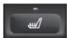
Press to switch on the heater. Press the button a second time to switch off the heater.
The heater is thermostatically controlled and maintains a constant seat temperature until either the heater is switched off or the ignition is switched off.
Traction Control Switch
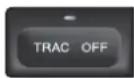
The traction control system is always on when the ignition is switched on. If required, the system may be switched off using this switch.
The traction control warning lamp in the switch will illuminate when this button is pressed to warn you that the system is switched off.
Hazard Warning Lights
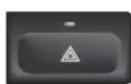
The hazard warning light switch is located at the driver's end of the supplementary switch panel. When pressed, the external indicator lights and side repeater lights will flash in unison.
Press the switch again to turn off the hazard lights.
Caution: Observe local laws on the use of hazard lights
Fuel Flap and Boot Release Switches
These switches are located at the outer end of the facia on the drivers side of the car.
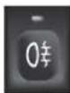
Fuel Flap Switch
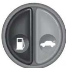
natural_image
Circular icon with a fuel pump symbol and a car silhouette, no text or numbers present.With the ignition turned on, press the fuel switch to open the fuel filler flap.
To close the filler flap, press down on the flap until the lock engages.
Boot (Trunk) Release Switch
There are three methods for opening the boot.
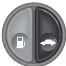
natural_image
Circular icon with a fuel pump and car symbol, no text or numbers presentThe boot may be opened by pressing the boot release switch located at the outer end of the facia. This switch will be active at any time when the alarm system is off, and the vehicle is stationary.
The boot lid may be opened at any time when the ignition is switched off using the lower right hand button on the key fob. This button will open the boot even when the vehicle is locked and the alarm is armed.
The boot may be opened from outside the car using the release button when the alarm system and ignition are switched off and the vehicle is unlocked and stationary.
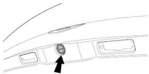
natural_image
Line drawing of a car interior panel with a circular button labeled 'A' pointing to the center (no text or symbols beyond the label)Close the boot lid gently and press down until the latch engages.
Caution: Slamming of the boot lid may damage the boot lock and seals.
Boot Contents
The following items are mounted in the boot (trunk) front wall:
• T he CD Autochanger
• T he Satellite Navigation DVD Player
• T he Battery Conditioner Socket
• T he Battery Disconnect Switch
The CD and DVD players are described in the Audio/Navigation section of this Owner's Guide.
The Battery Conditioner and the Battery Disconnect Switch are described in the Owner Maintenance section.
Cigar Lighter and Ashtray (Optional)
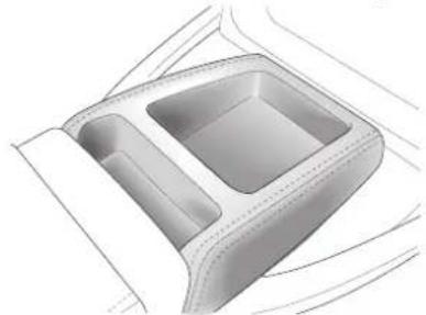
The standard centre console is fitted with a storage tray.
natural_image
Technical line drawing of a car interior frame with two compartments (no text or symbols)Alternatively, the centre console may be fitted with a cigar lighter and ashtray or a cup holder.
natural_image
Line drawing of a multi-compartment drawer with a central sink and side compartments (no text or symbols)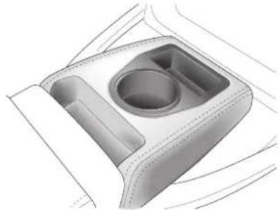
natural_image
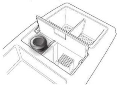
3D rendering of a car interior compartment with a central circular recess and two side compartments (no text or symbols)The cigar lighter is located under the ashtray cover and may be used when the ignition switch is in positions I or II. It is heated by pushing down until it clicks. The lighter will pop up when ready for use.
WARNING: The cigar lighter is heated to "Red Heat" when in use. Take care to avoid burns and do not allow children to play with the lighter.
The ashtray may be removed for cleaning by opening the lid and pulling the tray upwards. After cleaning it should be replaced and pushed down until the locating springs click into position.
Accessory Sockets
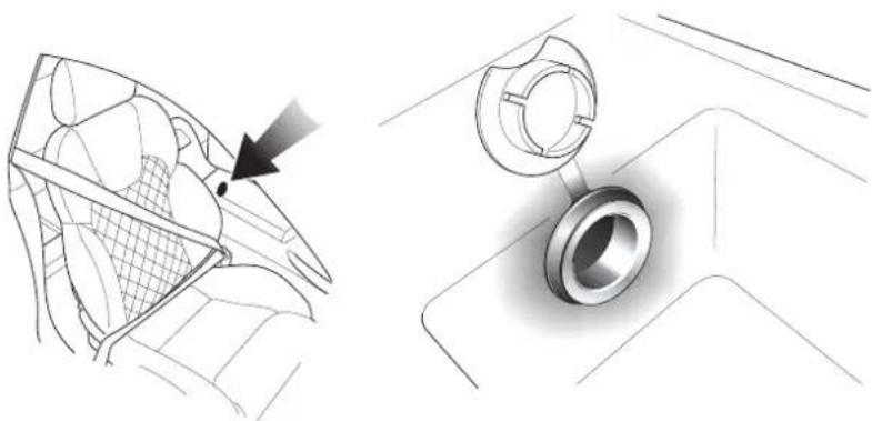
The primary accessory socket is mounted in the rear wall of the centre console storage box and may be used to power any 12 volt vehicle accessory requiring a current of less than 15 amps.
A second accessory socket is mounted under the front ashtray cover if the non-smoking trim option is fitted
natural_image
Technical illustration showing a mesh net and a bearing assembly (no text or symbols)The accessory socket is only live when the ignition key is inserted and the switch is turned to position I or II.
WARNING: Damage to the electrical circuits will result if more than 15 amps is drawn from the accessory socket. Only connect accessories which are designed for use in a motor vehicle.
Read the manufacturer's instructions and ensure that you do not connect any device which would exceed the current rating of the accessory socket.
Caution: Prolonged use of the accessory socket when the vehicle is stationary may seriously discharge the battery.
Bonnet (Hood) and Boot (Trunk)
Bonnet (Hood) Release
natural_image
Diagram of a device with a downward arrow indicating compression or disassembly (no text or symbols present)The bonnet release lever is situated on the outside of the left hand front footwell. Push down the lever to release the bonnet latches. The bonnet will be released and will rise until captured by the bonnet safety catch.
Bonnet (Hood) Safety Catch
natural_image
Mechanical component diagram showing a clamp and screw assembly (no text or symbols)The bonnet safety catch is located under the bonnet front edge.
Push down slightly on the bonnet front edge whilst pulling upward on the bonnet safety catch to release it. Lift the bonnet until fully open. The bonnet is held open by two gas struts.
Closing the Bonnet (Hood)
To close the bonnet, hold near the centre of the front edge and lower until approximately 18 inches (450 mm) from the latch mechanism and then release it. After closing the bonnet, ensure that the latch has fully engaged.
WARNING: Before closing the bonnet, ensure that no one is obstructing the closing area and that hands and clothing are clear. Remove tools, cleaning cloths, etc. from the engine compartment.
Electric Window Switches
natural_image
Line drawing of a car door with two buttons and a lock (no text or symbols)Two identical rocker switches are mounted in the driver's door to control the movement of the electric windows.
With the ignition on and the doors closed, press and hold the down arrow to lower the window.
WARNINGS: Drivers must advise all occupants of possible danger and ensure that all obstructions are clear before raising the window.
Press and hold the up arrow to raise the window.
Electric Window 'One Touch Down' Feature
Briefly press and release the down arrow to lower the window fully. Pressing the button again will stop downward window movement.
WARNINGS: Clear all obstructions before raising the window. When leaving the vehicle, remove the ignition keys. Misuse of window switches, especially by children, can result in injury due to entrapment in the window closure.
Note: If battery power to the electric windows has been interrupted for any reason, they will fail to operate correctly until reset using the procedure described in 'Owner Maintenance'.
C - Controls
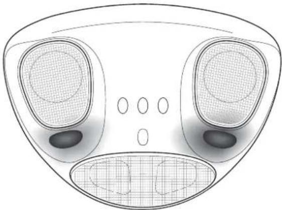
Interior Lights
The interior light assembly is mounted in the front windscreen header rail and contains two interior lamps. The lamps are manually controlled by the individual switches on the lamp assembly.
The interior lamps are automatically switched on for two minutes by either disarming the alarm or by opening either door. The lamps will extinguish when the engine is started or after two minutes.
natural_image
Technical line drawing of a mechanical component with two circular components and a grid-patterned base (no text or symbols)HomeLink Universal Transceiver (Optional)
This optional transceiver may be used to remotely open garage doors or gates or to remotely switch on home lighting devices etc. After programming the transmitter using the following procedure, up to three devices may be operated by the HomeLink transceiver.
Warning: Current US safety standards require that a garage door opener must be able to detect an object, stop and reverse. Do not use the HomeLink transceiver with any door opener device which does not have these features.
natural_image
Top-down technical drawing of a device's front panel with three circular ports and a central display (no text or symbols)The transceiver is mounted in the interior light assembly and has three buttons which may be programmed to control up to three radio frequency controlled devices
Programming
Note: If the door opener is fitted with an external antenna, ensure that the antenna is hanging straight down.
-
Switch off the engine.
-
Press and hold the two outermost buttons on the transceiver for approximately 20 seconds until the indicator light begins to flash.
-
Hold the end of the hand held transmitter of the device approximately 1-3 inches (25-75cm) away from the HomeLink surface, keeping the indicator light in view.
-
Simultaneously press the hand-held transmitter button and the chosen HomeLink button. The HomeLink indicator will flash slowly and then rapidly. When the rapid flashing commences to indicate successful programming, release both buttons.
-
To programme the remaining buttons, follow only steps 3 and 4.
If programming is not successful, release both buttons and repeat the procedure starting at step 2. However, position the hand held transmitter at a different angle or distance.
Some devices may require you to cycle the hand-held transmitter button every two seconds during programming. Consult the manufacturers instructions.
When programming such a door opening device, disconnect the motor to avoid excessive stress on the motor.
Rolling Code Programming
Rolling code devices may be identified as follows:
- Refer to the manufacturers specification for the device.
- T he hand held transmitter appears to programme the HomeLink transceiver but does not activate the garage door.
- Press and hold the programmed HomeLink button. The device has a rolling code feature if the HomeLink indicator flashes rapidly and then turns hard on after two seconds.
To programme a device with a rolling code feature, proceed as follows:
- Locate the 'training' button on the door opener receiver.
Note: Exact colour and location of the training button will vary with device manufacturer. Consult the manufacturers instructions.
- Note: Following step 2 you have 30 seconds to initiate step 3.
Firmly press and release the training button on the garage door receiver to activate the 'training' light.
- Firmly press and release the required HomeLink button. Press and release the HomeLink button a second time to complete the programming.
The device should now recognise the HomeLink signal and activate when the programmed button is pressed.
Operation
Move within range of the programmed device, press and hold the programmed HomeLink button to activate the device. Release the button when the device begins to activate.
Reprogramming a HomeLink Button
To programme a device to a HomeLink button previously used, follow these steps.
- Press and hold the desired HomeLink button. Do not release until step 4 is completed.
- When the indicator light begins to flash slowly after approximately 20 seconds, position the hand-held transmitter 1-3 inches (25-75mm) from the HomeLink surface.
- Press and hold the hand-held transmitter button.
- The HomeLink indicator light will flash, first slowly and then rapidly. when the rapid flashing commences, release both buttons.
The previous device has now been erased and the new device can be activated by pressing the newly programmed button. This procedure will not effect other programmed HomeLink buttons.
Erasing Programmed HomeLink Buttons
Individual buttons cannot be erased, however, to erase all three buttons:
- Press and hold the two outermost buttons until the indicator light begins to flash after about 20 seconds.
- Release both buttons.
The HomeLink transceiver is now in learn mode and can be reprogrammed at any time using steps 3 and 4 of the programming procedure.
Warning: It is recommended that you erase all information from the HomeLink transceiver before selling or disposing of the vehicle.
D - Driving
Contents
Checks Before Driving 1-D-2
Fuel 1-D-2
Fuel Filling 1-D-4
Catalytic Converters 1-D-4
Fuel Cut-Off Switch 1-D-5
Running-In 1-D-6
Maximum Engine Speed - Fuel Cut-Off 1-D-6
Driving in Wet Conditions 1-D-6
The Ignition Lock 1-D-7
Warning Light Indications at Ignition On 1-D-8
Starting the Engine - Hot or Cold 1-D-9
Stopping the Engine - Removing the Ignition Key 1-D-10
Gear Changing 1-D-11
General Description 1-D-11
Clutch Operation 1-D-13
Handbrake Operation 1-D-14
Securing the Vehicle when Stationary 1-D-14
Starting the Engine 1-D-15
Driving 1-D-17
Selecting Reverse 1-D-18
Stopping the Vehicle and the Engine 1-D-19
Driving in ASM - 'Auto Shift Mode' 1-D-20
Wheel Slip Protection (WSP) 1-D-21
Sport Mode 1-D-22
Summary of Basic Select Shift Mode Operation 1-D-23
Traction Control System 1-D-25
The Braking Systems 1-D-27
Brake System Safety Features 1-D-27
Bedding-In of New/Replacement Brake Pads 1-D-28
Anti-Lock Braking System (ABS) 1-D-29
Brake Warning Indications During Driving 1-D-30
The Handbrake (Parking Brake) 1-D-31
Rear Parking Assistance (Optional) 1-D-32
D - Driving
Checks Before Driving
Inspect the car to make sure that everything is according to the information and specifications in this Owner's Guide.
Outside the car:
Visually check the wheels, wheel nuts and tyres.
Check that all windows, mirrors and lights are clear and unobstructed.
Check that the boot, bonnet and fuel filler flap are securely closed.
Check the operation of all lights.
Once you are in the car:
Check that the doors are securely closed.
Check that the seat, mirrors and steering wheel adjustments are correct.
Check that all gauges and indicators are reading correctly.
Check that the seat backs are in an upright position.
Check that all occupants have fastened their seat belts.
Fuel
The Vanquish uses 95/98 RON Unleaded Fuel only (USA - Premium Unleaded). For optimum performance and extended high speed driving, the use of 98 RON unleaded fuel is recommended.
Fuel capacity is 80 litres (17.6 Imp gallons / 22 US gallons).
The Low Fuel warning lamp will illuminate when approximately 16 litres (3.5 Imp Gallons / 4.4 US Gallons) remain.
Note: Only about 11 litres (2.5 Imp Gallons/3.0 US gallons) of the reserve may be used. This gives sufficient fuel for approximately 80 kilometres (50 miles) of normal motoring.
1-D-2
D - Driving
Fuel Filler Cap
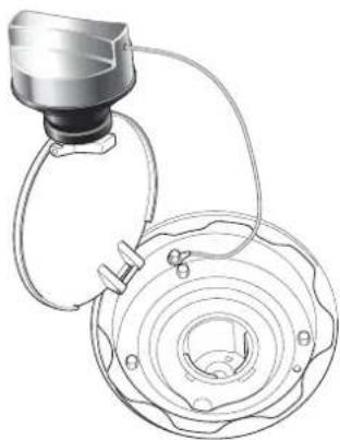
natural_image
Technical line drawing of a mechanical component with concentric rings and a connecting rod (no text or symbols)The fuel filler cap is located on the left side of the car, to the left of the boot (trunk) lid. The filler flap solenoid is enabled by turning off the alarm. The flap is released by pressing the release button on the facia.
Release the filler cap by rotating a quarter turn anticlockwise, then lift off the cap.
Temporarily store the cap on top of the filler flap as illustrated.
Filler Flap Emergency Release
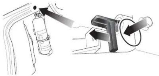
natural_image
Diagram showing a fire extinguisher and its internal components with directional arrows (no text or labels)If the filler flap will not open, release the filler flap solenoid manually as shown. On pulling back the solenoid lever, the filler flap is released and will open under spring pressure.
WARNINGS: Fuel vapour is highly flammable, toxic and explosive. Always switch off the ignition before refuelling. Do not overfill the fuel tank. Do not inhale fuel fumes.
Do not smoke or light a flame while refuelling. Do not use mobile phones at filling stations.
Never carry additional fuel in portable containers. They may leak, explode or cause a fire, whether full or partially empty.
If handled improperly, fuel can ignite or explode and cause injury.
Do not use the car if there is fuel leakage or a persistent smell of fuel.
D - Driving
Fuel Filling
The unleaded fuel tank filler neck has a restricted opening which will only accommodate the fuel supply nozzle of unleaded fuel pumps.
To avoid fuel spillage, stop filling at the first automatic cut-off of the fuel supply nozzle.
Refit the filler cap and rotate it clockwise until a 'click' is felt as the cap is fully tightened. Close and latch the fuel filler flap.
Catalytic Converters
The V12 Vanquish exhaust system contains catalytic converters which convert harmful exhaust gasses into less noxious substances and so reduce environmental pollution. Catalytic converters operate at high temperatures and continue to radiate a considerable amount of heat after turning off the engine.
WARNINGS:
Do not park over dry grass, leaves or other combustible material. A significant fire risk exists because of residual heat in the catalytic converters.
Do not drive through deep water. The rapid cooling of the catalysts may cause them to break up.
Leaded fuel will cause irreparable damage to the catalytic converters. If you do inadvertently put leaded fuel into a V12 Vanquish, DO NOT START THE ENGINE. DO NOT DRIVE THE CAR. Contact your Aston Martin Dealer immediately.
D - Driving
Fuel Cut-Off Switch
Your V12 Vanquish is fitted with an emergency fuel cut-off inertia switch mounted beneath the rear parcel shelf/left rear seat. This switch operates to cut-off the fuel supply and ignition circuits in the event of an accident, thereby reducing fire risk. If the engine cuts out and then does not restart following a minor impact, reset the switch as follows.
WARNING: To avoid the possibility of fire, do not reset the fuel cut-off switch if you smell fuel.
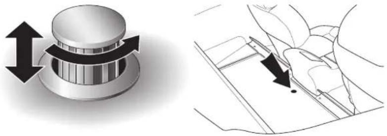
natural_image
Technical illustration showing a mechanical knob with bidirectional arrows and a schematic diagram of a flower (no text or symbols)2 + 0 Cars - Press the top of the release button, it will 'pop up'. Rotate the button clockwise to release the catch. Raise the parcel shelf.
2 + 2 Cars - Remove the left rear seat.
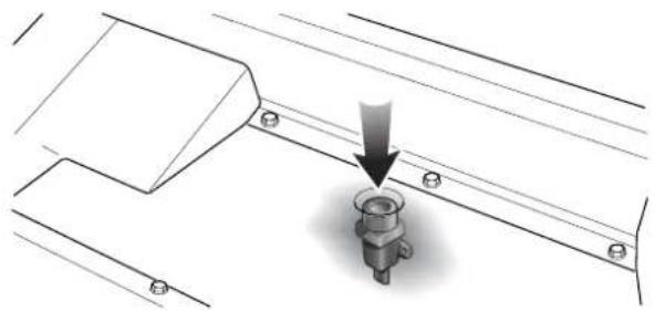
natural_image
Technical diagram showing a mechanical assembly with a downward arrow pointing to a bolted component (no text or symbols present)Press the top of the fuel cut-off switch until it latches down. With the ignition on, the fuel pumps will then run and fuel will again be supplied to the engine. Restart the engine as normal.
D - Driving
Running-In
Your V12 engine is fully hot tested during manufacture and no special running-in procedures are necessary. Nevertheless it is prudent to limit engine loads (e.g. by accelerating gently and by using lower gears on steep hills or when negotiating tight turns) during the first 4,000 km (2,500 miles).
Maximum Engine Speed - Fuel Cut-Off
The maximum safe engine speed is 7,200 RPM. If this speed is exceeded, fuel supply to the engine is reduced. As the engine speed reduces back to a safe level, fuel supply is progressively restored.
Driving in Wet Conditions
When driving in wet conditions, water can build up under your tyres so that they ride on a layer of water. This is called aquaplaning or hydroplaning. When this happens, you have little or no control. Aquaplaning is more prone to happening at higher road speeds if there is a lot of water on the road and particularly if the tyres are also under inflated or approaching minimum tread depth. Slow down when it is raining.
It is important to take bends or curves at a safe, reasonable speed, particularly when driving on wet or slippery road surfaces.
Driving Techniques
The procedures for driving the V12 Vanquish will be unfamiliar to many new owners. Please take time to safely acquire the necessary new driving skills. Practise in safe, lower speed conditions before investigating the high performance potential of the car. Please ensure a safe and enjoyable entry into this new phase of Aston Martin motoring.
High performance driving courses are available via Aston Martin to enable customers to get the best from their car in the safest way.
1-D-6
D - Driving
The Ignition Lock
The Ignition Lock, located on the right side of the steering column, performs the following functions:
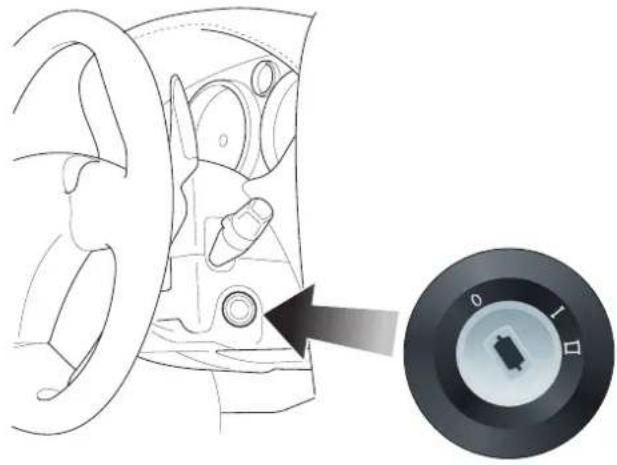
natural_image
Diagram of a car interior showing steering wheel and dashboard, with a circular dial indicator showing rotary knob (no text or symbols)- Steering Lock
• A auxiliaries Switch - Ignition Switch
The ignition lock has three positions:
Position OAll systems off, steering lock engaged.
Position I Steering lock released. Auxiliaries on (e.g. radio). Use this position if the vehicle is being towed.
Position II Steering lock released. Ignition and all other electrical systems on. This is the normal running position.
1-D-7
D - Driving
Warning Light Indications at Ignition On
As the ignition is switched on, the electronic control units each complete a self check to ensure correct operation. During these checks, all lights on the instrument panel will illuminate for about 5 seconds and SYSTEM CHECK will appear on the message display. Under normal circumstances most warning lamps will extinguish at the end of the individual system checks (e.g. engine management, transmission control, airbag control, ABS control and tyre pressure warning lamps should all extinguish if the results of their system checks are satisfactory). The following lamps will normally remain on:
- The Seat Belt warning light remains illuminated if the driver's seat belt is not fastened. On fastening the seat belt, the warning lamp will extinguish.
• T he Airbag warning lamp will extinguish on satisfactory completion of the airbag system self-check.
Warning: Do not drive if the seat belt or airbag warning lamps remain on. Have the suspect system checked by your Aston Martin dealer.
• T he handbrake warning light will remain illuminated until the handbrake is released.
• T he oil pressure warning lamp will remain illuminated until the engine starts.
• T he battery warning lamp will remain illuminated until the engine starts and battery charging commences.
Note: Other Information lights may remain on (e.g. Main Beam Warning or Low Screen Wash) dependant on the current vehicle state and switch settings.
If either the ABS or Brake Fluid Warning lights remain illuminated, do not drive the car. Refer to the description of Brake Warnings during Driving later in this section.
Starting the Engine - Hot or Cold
WARNINGS: Before driving the vehicle, ensure that you are wearing appropriate footwear to efficiently operate the floor mounted pedals. Ensure that floor mounted pedal movement is not restricted by floor mats or other objects trapped beneath the pedals.
Insert the ignition key and rotate it to position II. Apply the footbrake. Pull back both gear shift paddles simultaneously to select Neutral and check that the handbrake is applied.
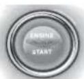
Press the illuminated ENGINE START button, wait until the engine fires, then release the button.
Note: Do not press the accelerator during engine starting. The Electronic Engine Management System automatically compensates for cold or hot start conditions and makes appropriate adjustments to the fuel/air mixture and engine idle speed without driver intervention.
Warning: Do not touch the throttle pedal until you have engaged a gear and wish to move off. The clutch engages automatically as engine speed is increased above idle. The vehicle will move off if the throttle is opened with a gear engaged.
D - Driving
Stopping the Engine - Removing the Ignition Key
To stop the engine, apply the handbrake and turn the ignition key anticlockwise to position 0.
The ignition key is interlocked with the handbrake mechanism so that the key may only be removed from the ignition lock when the hand-brake is applied.
Preventing Unnecessary Battery Drain
Caution: Always remove the ignition key immediately after switching off the ignition
Some circuits remain active when the ignition is switched off and the key remains in the ignition lock. Current flow in these circuits only ceases when the ignition key is removed. If the key is left in the ignition lock, unnecessary current will be drawn from the battery.
A temporary label is fitted to all new cars to remind drivers to remove the ignition key whenever the ignition is switched off.
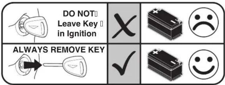
Always use the battery disconnect switch and the battery conditioner to maintain battery charge level when garaging the car for some days. (See pages 1-G-23 to 1-G-26 in this Owner's Guide).
1-D-10
Gear Changing
General Description
Primary Gearshift Control
The V12 Vanquish transmission system is based on a standard six speed manual gearbox and clutch with 'sequential paddle shift' operation.
The gearshift and clutch functions are automatically operated when a gearshift is requested and hence no gear-lever or clutch pedal are fitted. Gearshift operations are controlled using two levers or 'paddles', one on either side of the steering column.
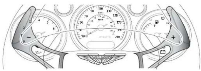

Warning: When the V12 Vanquish is at rest with the engine speed below about 1300 rpm the clutch will be automatically opened. The brakes must be used to prevent the vehicle rolling on any incline.
1-D-11
natural_image
Pure geometric diagram with intersecting lines and circular shapes (no text or symbols)
natural_image
Pure geometric diagram with intersecting lines and a circular pattern (no text or symbols)D - Driving
Secondary Transmission Controls
Additional gearbox functions are controlled by four supplementary switches, two on either side of the engine start button.
Note: The order of these switches is reversed on a left hand drive vehicle.
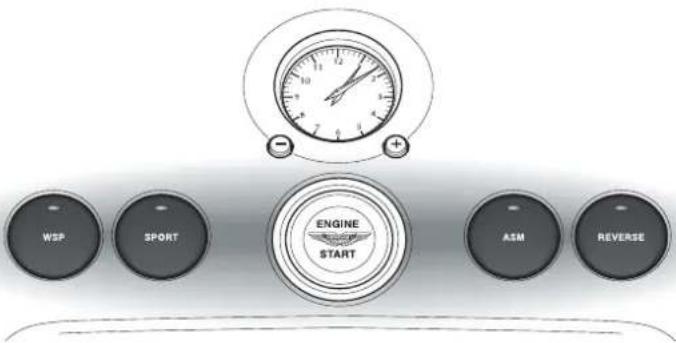
REVERSE = Selects reverse from neutral or first gear
ASM = Switches on/off Auto Shift Mode
SPORT = Engages Sport mode
WSP = Engages the Wheel Slip Protection function
D - Driving
Clutch Operation
The clutch is automatically operated by the transmission controller and is normally open when the engine is at idle speed. The clutch is normally fully closed at engine speeds above about 1300 rpm.
When moving off, allow the clutch to fully engage before applying full engine power.
When reversing, keep engine speed above 1300 rpm whenever safe to do so.
DO NOT hold the vehicle on a slipping clutch (e.g. at traffic lights or road junctions).
Warning: When the vehicle is at rest with the engine speed below about 1300 rpm the clutch will be open. the brakes must be used to prevent the vehicle rolling on any incline.
Clutch Warning Lamp
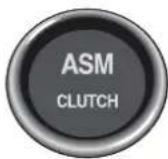
The clutch warning lamp will illuminate if the clutch becomes excessively hot due to slipping.
Should the clutch warning lamp come on, immediately correct the cause of the clutch slip by either reducing engine speed to idle (to open the clutch) or by increasing engine power to fully engage the clutch.
Caution: Clutch damage caused by misuse of the vehicle will not be covered under the Aston Martin Warranty.
In order to protect the clutch assembly, engine speed will be automatically restricted to 4000 rpm whilst the clutch warning lamp is illuminated.
Full engine power will be made available again, after the clutch has cooled, the warning lamp has extinguished, and the throttle pedal has been fully released.
1-D-13
D - Driving
Handbrake Operation
The handbrake fitted to the vehicle always returns to the lower position.
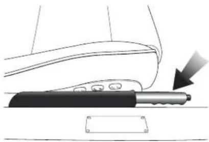
natural_image
Diagram of a car seatbelt with a hand holding a tool, showing no text or symbolsTo engage the handbrake, pull up firmly on the lever without pressing the button. The handbrake will be applied and the warning lamp will illuminate. Release the lever to its lowest position.
To release the handbrake, lift the lever until resistance is felt, press the end button and release. Check that the handbrake warning lamp is extinguished.
Securing the Vehicle when Stationary
The V12 Vanquish transmission system is based on a standard manual gearbox and clutch. If the vehicle is parked on an incline and the hand-brake and footbrake are released, the vehicle will roll down the incline. Always secure the vehicle with the brakes when at rest.
Warning: When the V12 Vanquish is at rest with the engine speed below about 1300 rpm the clutch will be automatically opened. The brakes must be used to prevent the vehicle rolling on any incline.
1-D-14
D - Driving
Starting the Engine
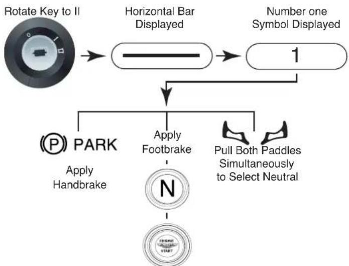
flowchart
graph TD
    A["Rotate Key to II"] --> B["Horizontal Bar Displayed"]
    B --> C["Number one Symbol Displayed"]
    C --> D["Apply Footbrake"]
    C --> E["Pull Both Paddles Simultaneously to Select Neutral"]
    D --> F["PARK Apply Handbrake"]
    E --> G["START"]
When Starter button illuminates, Press Engine Start
When Engine Fires and Runs Release Starter Button
Insert the ignition key and rotate to position II. The gear position indicator within the instrument panel will initially display a horizontal bar during the system self-check, and will then flash a 1 symbol.
The driver must select neutral before the engine can be started.
With the handbrake applied, press the footbrake and pull both gearshift paddles simultaneously to select neutral.
'N' will be displayed and the starter button will be illuminated.
1-D-15
D - Driving
Press the red 'Engine Start' button, wait until the engine fires, then release the button. The button illumination will extinguish.
Caution: Do not press the accelerator during engine starting for the following reasons:
a) The electronic engine management system automatically compensates for cold or warm start conditions and makes appropriate adjustments to the fuel/air mixture and ignition timing without driver intervention.
b)'Blipping' of the throttle must be avoided, it would cause intermittent partial clutch engagement and excessive wear on the clutch mechanism.
1-D-16
Driving
Engaging First Gear
With the handbrake fully applied and the footbrake pedal pressed, pull the +paddle once the engage first gear.
Note: If you wish to move of in second gear, pull the + paddle twice in quick succession. Second gear will be engaged instead of first.
Moving Off
Release the footbrake and gradually increase engine speed. The system will progressively engage the clutch as engine revs increase. Release the handbrake as the clutch engages, the vehicle will move off.
Changing Up to a Higher Gear
When safe and appropriate to do so, accelerate using the throttle. Change up by pulling and releasing the +paddle. Repeat the acceleration and change up sequence to move up through the gear range 1-6.
Note: A smoother upshift can be achieved by slightly lifting off the throttle during any upward gearchange and progressively re-applying the throttle when the change is completed.
The system will upshift automatically if engine speed rises above the upper operating limit.
Changing Down to a Lower Gear
Decrease vehicle speed by reducing throttle demand and braking if necessary. As engine revs decrease, change down by pulling and releasing the -paddle. Repeat as necessary to shift down through the gear range 6 - 1.
Note: If the driver does not downshift during speed reduction, gears will downshift automatically as engine speed drops below 1300 rpm in each gear.
1-D-17
D - Driving
Selecting Reverse
If the vehicle is stationary in neutral:

Hold the footbrake pressed and press the reverse button. The red LED on the button will illuminate and 'R' will be displayed in the gear position indicator.
If the vehicle is stationary in first gear:

Hold the footbrake pressed and press the reverse button. The system will engage neutral and 'N' will be displayed. Press the reverse button again to select reverse. The red LED on the button will illuminate and 'R' will be displayed in the gear position indicator.
Deselecting Reverse
With the footbrake pedal pressed, either:
Pull both paddles together to select neutral.
or,
Pull the right paddle once to select neutral and a second time to select first gear.
1-D-18
Stopping the Vehicle and the Engine
Bringing the Vehicle to Rest
Bring the vehicle to a stop using the brakes. If not already selected by the driver, lower gears are selected automatically as engine speed drops below 1300 rpm. As the vehicle stops, the clutch opens and first gear is automatically engaged.
Warning: When the vehicle is at rest with the engine speed below about 1300 rpm the clutch will be open. the brakes must be used to prevent the vehicle rolling on any incline.
The vehicle is then ready to move off immediately when the accelerator is pressed.
The vehicle will remain in first gear as long as the brake pedal is depressed.
If the brake pedal is released, neutral will be selected after a 10 second delay and a warning buzzer will sound.
Stopping the Engine, Removing the Ignition Key
To stop the engine, first apply the handbrake then turn the ignition key to position O.
If the handbrake is not applied, the key can only be turned to the "Auxiliary" position and an audible warning will be sounded.
D - Driving
Driving in ASM - 'Auto Shift Mode'
Selecting Auto Shift Mode
Warning: As in Select Shift mode, when the vehicle is in ASM mode and comes to rest with the engine speed below about 1300 rpm the clutch will be open. There is no drive to the road wheels and the vehicle will be free to roll. The brakes must be used to prevent the vehicle rolling on any incline.
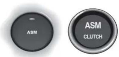
ASM can be selected at any time when the engine is running. Press the ASM button in the centre console, the button will be illuminated to indicate that ASM mode is active. In addition, the green ASM lamp in the instrument panel will illuminate.
Moving Off
With the footbrake pedal pressed, pull the paddle to engage first gear. Release the footbrake and gently increase engine speed. Release the handbrake as the clutch engages and the vehicle moves off.
Gearshifts
Increase vehicle speed, the system will automatically change up as necessary.
Decrease vehicle speed, the system will automatically change down as necessary.
Deselecting Auto Shift Mode
Deselect the ASM mode by pressing the ASM button. This mode will also deselect immediately if either paddle is operated.
1-D-20


D - Driving
Wheel Slip Protection (WSP)
This mode is designed to reduce the risk of wheel slip in any conditions where tyre to road adhesion may be impaired (e.g. snow, ice, rain, etc.).
Selecting Wheel Slip Protection
Warning:
Engage wheel slip protection only when the vehicle is stationary. If wheel slip protection is engaged when the vehicle is in motion, unexpected gear changes could occur which may de-stabilise the car
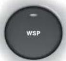
Press the WSP button located in the centre console. The red LED in the button will illuminate and remain on to indicate that wheel slip protection is active.
When WSP is active, gear upshifts will occur at about 3,200 rpm. During normal driving, engine torque will be limited to reduce the risk of wheel slip through excessive engine power.
1-D-21
D - Driving
Sport Mode
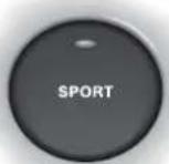
Sport mode may be selected at any time when driving in Select Shift mode or in ASM mode.
Press the Sport button. The red LED will illuminate to show that Sport mode is active.
When driving in Sport mode, gear changes will be accelerated. In addition, Sport mode will allow the engine to run up to maximum speed. Maximum engine rpm before a gear upshift will be controlled by the rev limiter rather than by the transmission controller as normal.
When driving in ASM mode, the sport function will give a more sporting shift pattern with downshifts occurring at lower throttle demands and upshifts occurring at higher engine speeds.
Summary of Basic Select Shift Mode Operation
Starting the Engine
Sit in the vehicle, door closed, ignition on. Gear display normally indicates '1' after completion of the system self check. Depress the footbrake and pull both paddles together to select neutral (N is displayed). Press 'Start' to start the engine.
Moving Off
With the foot brake pedal pressed, pull the paddle once to engage 1st gear. Release the footbrake, gently increase engine speed and release the handbrake as the vehicle moves off.
Changing Up
Increase vehicle speed, change up by pulling and releasing the +paddle. Repeat as necessary to shift up through the gear range 1 - 6.
Changing Down
Decrease vehicle speed, change down by pulling and releasing the — paddle. Repeat as necessary to shift down through the gear range 6 - 1.
Stopping
Bring the vehicle to a stop using the brakes. Lower gears are selected automatically. As the vehicle stops, the clutch opens and 1st gear is engaged.
Warning: When the vehicle is at rest with the engine speed below about 1300 rpm the clutch will be open. the brakes must be used to prevent the vehicle rolling on any incline.
D - Driving
Turning Off the Engine
Apply the handbrake, turn the key to 'O' and remove the key.
Selecting Reverse
With the vehicle stationary, press the footbrake and press the 'R' button twice (First press shifts from 1 to N, second press shifts from N to R). If in Neutral, press once only.
Deselecting Reverse
When reverse is engaged, press the footbrake and pull the +paddle to select neutral.
D - Driving
Traction Control System
On/Off Switch
The traction control system is always operational when the ignition is switched on. The traction control system can be switched off at any time using the switch in the centre console.
If traction control is switched off, the switch warning lamp will remain illuminated to warn that traction control is not operational.
Traction Control Warning Lamp
The switch warning lamp informs the driver of the traction control system status as follows:
Ignition switched on - warning lamp on during system self-check.
Ignition on, warning lamp off - System active but not operating. During normal operation, the light remains off until wheel slip is detected. The warning lamp will then flash whilst the system controls the wheel slip.
Ignition switched on, warning lamp permanently on (i.e. lamp never extinguishes) - System faulty and inoperative, consult your dealer as soon as possible.
Ignition on, TRAC OFF button pressed - warning lamp permanently on to warn that traction control is inoperative.
1-D-25
D - Driving
Traction Control Operation
WARNING: In all cases it remains the drivers responsibility to drive safely according to the law and with due regard to prevailing conditions. The fact that a vehicle is equipped with Traction Control must never allow the driver to be tempted into taking risks which could affect his/her safety or that of other road users. The addition of Traction Control cannot overcome the consequences of applying too much engine power for the prevailing conditions.
The traction control system is designed to limit engine power when driven wheel slip is detected. This most commonly happens when accelerating on a slippery road or loose surface.
The system uses the vehicles ABS sensors to monitor the wheel speed of all four road wheels. As soon as a driven rear wheel starts to spin due to the application of too much power for the available grip, the system automatically reduces engine power by temporarily adjusting the fuel supply. The brake on the slipping wheel will also be applied as necessary until the wheel speed matches that of the other wheels.
During activation, the system warning light will flash. The driver may experience a loss in power or temporary 'misfire' as engine power is reduced. These symptoms are normal and will clear as wheel spin is eliminated and normal engine power is restored.
If traction control cuts in when driving on extended icy or slippery surfaces, reduce engine power as necessary until the traction control warning light is extinguished.
CAUTION: Do not maintain engine power at such a level that traction control is activated for long periods (more than about one minute). The reduced fuelling levels to the engine will cause the exhaust catalysts to overheat. Overheating of the exhaust catalysts can destroy them.
D - Driving
The Braking Systems
The Footbrake System
V12 Vanquish uses a vacuum boosted hydraulic braking system with Electronic Brake Force Distribution (EBD) and anti-lock braking (ABS) function. These systems ensure that braking performance is in keeping with the vehicle performance.
The EBD system monitors wheel speed and regulates brake pressure as necessary to reduce the possibility of wheel slip. This system is designed to prevent premature activation of the ABS system
The Anti-Lock Braking System (ABS) is continually monitored for correct operation whilst the ignition is switched on. Should a fault occur, it will be signalled by the Anti-Lock Warning Light.
Brake System Safety Features
The brake system tandem master cylinder is designed so that in the worst case (barring catastrophic accident damage), only half the brake system could fail. Even in the event of a major brake pipe fracture, at least two wheels will have fully operative brakes.
1-D-27
D - Driving
Bedding-In of New/Replacement Brake Pads
To ensure that brake pads and discs are correctly 'bedded-in' on new cars, the factory road test the car and perform the following brake bedding-in procedure:
- Three light brake applications from 80-50 kph (50-30 mph) using normal acceleration to 80 kph (50 mph).
- Three medium applications from 110-65 kph (70-40 mph) using normal acceleration up to 110 kph.
- Two hard applications from high speed to 50 kph (30 mph), again using normal acceleration.
- Drive a further 8 km (5 miles) with minimal brake use.
- Stop and allow the brakes to cool.
- Drive a further 8 km (5 miles) back to the workshop with normal brake use.
Aston Martin dealers are required to perform this routine each time brake pads / discs are replaced.
Aston Martin require owners to perform this routine if pads or discs are replaced by a non-franchised workshop who will not know of the correct bedding in procedure.
Failure to bed-in the brake pads / discs will result in reduced brake performance and possible brake judder or squeal.
Anti-Lock Braking System (ABS)
The Teves Mk 20 anti-lock braking system (ABS) fitted to the V12 Vanquish helps prevent the road wheels from locking and skidding during emergency braking. This also helps steering and directional stability to be maintained.
If, in an emergency braking situation, the braking force applied begins to exceed the tyre/road adhesion, the ABS system is activated to prevent the road wheels locking. When this happens a pulsating effect is felt through the brake pedal. This is a normal ABS effect.
V12 Vanquish is also fitted with Electronic Brake Force Distribution (EBD). EBD acts to redistribute brake pressure between the wheels to reduce wheel slip and delay the onset of full ABS operation.
WARNING: In all cases it remains the drivers responsibility to drive safely according to the law and with due regard to prevailing conditions. The fact that a vehicle is equipped with ABS must never allow the driver to be tempted into taking risks which could affect his/her safety or that of other road users. The addition of ABS cannot overcome the consequences of trying to stop in too short a distance, cornering at too high a speed, or the risk of aquaplaning - where the tyres are prevented from contacting the road surface by a layer of water.
The driver should always take road conditions into account. A slippery road surface always requires more braking distance for a given speed, even with ABS. Possible extensions of stopping distance compared to locked wheels may occur during ABS operation on slushy snow, gravel, sand or certain heavily corrugated or ridged warning sections of road surfaces.
If any braking system malfunction occurs, immediately have the Braking and ABS systems checked by your Aston Martin Dealer.
D - Driving
Brake Warning Indications During Driving
V12 Vanquish electronic control units continue to monitor correct operation of the braking sub-systems while the vehicle is being driven. Two brake warning lights are of particular importance.
The Anti Lock Braking (ABS) Warning Light
The ABS system is monitored for correct operation while the ignition is switched on. If a fault is detected, the Anti-Lock warning light will illuminate and the ABS system will be partly or fully disabled.
The normal braking system will continue to function without anti-lock but with full vacuum boosted braking to all road wheels being maintained. In the event of an ABS fault, consult your Aston Martin Dealer immediately.
WARNING: If the ABS warning light illuminates, you should be aware that wheels could lock during extreme braking or when braking on slippery surfaces.
The Brake System Warning Light
BRAKE

The braking system is continuously monitored for fluid level. If only the brake warning light illuminates, it indicates that the brake fluid has fallen below the acceptable level. It is essential that the braking system is checked immediately, preferably by an Aston Martin Dealer.
WARNING: If the brake warning light illuminates, you should immediately be prepared for possible increased stopping distances and possible partial failure of the braking system.
1-D-30


D - Driving
The Handbrake (Parking/Emergency Brake)
The handbrake lever is situated on the outside of the drivers seat. The handbrake operates on a dedicated caliper on the rear wheel brake discs.
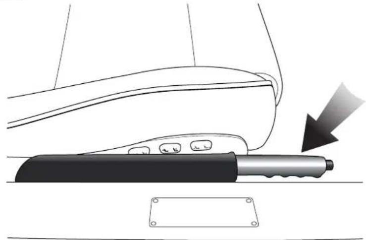
natural_image
Diagram of a car door handle with a tool and arrow indicating motion (no text or symbols)BRAKE

To engage the handbrake, pull up firmly on the lever without pressing the release button. The handbrake ratchet will latch and the brake warning light will illuminate. Note that this lamp is the only indication that the handbrake is applied. The lever can then be lowered to its fully down position.
To release the handbrake, pull up on the lever against spring pressure, press and hold the lock release button whilst lowering the lever to its maximum down position.
The brake warning light extinguishes as the handbrake is fully released.
Caution: Always check that the warning lamp is correctly extinguished before moving off. Do not attempt to drive the vehicle if the warning lamp remains on.
1-D-31
D - Driving
Rear Parking Assistance (Optional)
The optional ultrasonic reversing sensor system will assist in detecting obstructions as the car is reversed towards them.
Warning: These sensors do not replace the need for total vigilance when parking. Look all around when reversing and make full use of all mirrors to be aware of persons or objects in the vicinity of your car. Take appropriate measures to protect them from danger.
When the distance between the car and any detected obstruction is less than 1.7 metres (5.5 feet) an intermittent 'beep' signal will be heard. The 'beep' frequency will increase in pitch and becomes more persistent as you approach the obstruction. The sound becomes continuous at distances less than 30 centimetres.
Four sensors are mounted in the rear bumper. The sensors should be kept clear of dirt, snow etc. to ensure clean signals and accurate distance monitoring.
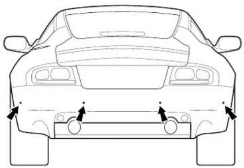
natural_image
Front view line drawing of a car showing rear and front views with directional arrows (no text or symbols)
natural_image
Circular metallic object with gradient shading, no text or symbols visibleWARNING: The distance sensors do not eliminate the need for caution when reversing. Furthermore, in heavy rain or similar adverse conditions, the sensors may not always be able to accurately measure the distance to close objects. Irregular obstacles may also cause inaccurate measurements due to their size and shape.
1-D-32
Contents
The Air Conditioning System 1-E-2
General Information 1-E-3
System Operation and Button Functions 1-E-4
Switching the System On 1-E-4
Automatic Operation 1-E-4
AUTO 1-E-4
Air Conditioning (A/C) 1-E-4
Temperature Selection 1-E-5
Defrost 1-E-5
Air Recirculation 1-E-5
Heated Front Screen (Optional) 1-E-6
Heated Rear Screen 1-E-6
Manual Fan Speed 1-E-6
Manual Air Distribution 1-E-7
External Temperature 1-E-7
Switching Off 1-E-8
Ventilation Airflow 1-E-8
Operating Tips 1-E-9
Hot Weather Operating Tips 1-E-9
Cold Weather Operating Tips 1-E-9
Air Distribution 1-E-10
System Fault Display 1-E-10
The Air Conditioning System
The air-conditioning system fitted to V12 Vanquish offers automatic control of temperature, fan speed and air distribution to maintain optimum comfort under most driving conditions. Manual controls are provided to allow the driver to override the automatic operation.
Control Panel
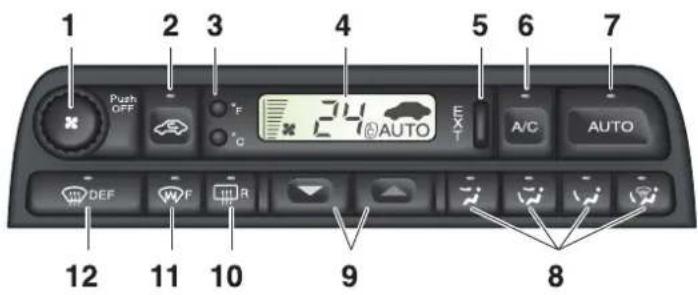
- Push to switch On or Off
Rotate for manual fan speed selection - Manual recirculation/outside air
- Centigrade/Fahrenheit selection buttons
- Display panel
- External temperature
- Air conditioning
- Automatic operation
-
Manual distribution
Face only
Bi-level (face and feet)
Feet only
Demist (Screen and feet) -
Temperature selection
Blue - Decrease
Red - Increase
-
Heated rear screen
-
Heated front screen (optional)
-
Defrost
General Information
Ensure that the air inlet grille at the base of the front windscreen is clear of leaves, snow or other obstructions.
A solar sensor is fitted on top of the fascia, this should not be covered when driving.
The intake grille of the in-car temperature sensor is located in the driver's knee bolster, close to the centre console. To ensure optimum temperature control this grille should not be obstructed.
Moisture which forms at the evaporator in the air conditioning unit is discharged via drain tubes onto the road underneath the vehicle. After stopping, small puddles of water may form underneath the vehicle. This is normal and does not indicate a system malfunction.
The refrigeration system (A/C button) should be run briefly at least once a week to lubricate the A/C compressor seal and prevent refrigerant leakage.
System Operation and Button Functions
Switching the System On
The system can be switched on by pressing one of the following:
AUTO button Switches the system on in automatic mode
DEF button Switches the system on in Defrost mode
A/C button Switches the system on at the last settings and with the refrigeration system working
Push Off knob Switches the system on at the last settings
Automatic Operation
Note: The fans will not operate until the engine is warm (except in defrost mode)
AUTO
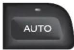
Press AUTO for optimum automatic control under most operating conditions. The word AUTO will appear in the display panel and the temperature, fan speed and distribution will be controlled automatically.
Air Conditioning (A/C)
Press to switch off the refrigeration system. Press again to switch on. The refrigeration system is automatically engaged when AUTO is selected
Note: All the year use of the air conditioning is recommended for optimum comfort, humidity control and to reduce interior misting.
Temperature Selection


The selected interior temperature is shown in the display panel. Press the 'red' button to increase the temperature. Press the 'blue' button to decrease the temperature.
Note: Automatic temperature control operates between 17^ C and 31^ C ( 61^ F and 90^ F). In addition, 'HI' and 'LO' settings provide maximum heating or cooling at maximum fan speed. Fan speed can be manually reduced if required.
Defrost

Press DEF to direct air to the front and side screens at maximum fan speed. This also switches on the heated front screen (where fitted). Fan speed can
be manually reduced as required. Press the DEF button again to return to the last setting or AUTO for automatic control.
Warning: Directing cold air onto the screen in warm humid conditions can produce external condensation droplets.
Air Recirculation
Closes the outside air intakes and recirculates air within the passenger compartment. Prevents unpleasant odours being drawn into the vehicle.
Two options of control are available:
- Press the button briefly to provide recirculation of interior air for a period of approximately five minutes.
- Press and hold the button until two 'beeps' are heard to provide continuous recirculation of interior air. Press the button again to switch off.
Warning: Do not use air recirculation for extended periods. Drowsiness may occur due to depletion of oxygen inside the car. Also, misting of the interior may occur in cold weather.
E - Heating, Ventilation & Air-Conditioning
Heated Front Screen (Optional)

With the engine running, press to switch on the heaters for rapid defrosting/de-icing of the front screen. The front screen heater is automatically switched on when DEF is selected but can be independently switched on or off at any time. The front screen heater switches off automatically after approximately six minutes.
Heated Rear Screen

With the engine running, press to switch on the rear screen heater and door mirror heaters. They can be independently switched off at any time but will switch off automatically after approximately 20 minutes.
Manual Fan Speed
Note: In AUTO the fans will not operate until the engine is warm.
Turn the knob clockwise to increase or anti-clockwise to decrease air flow. Fan speed is indicated in the display as a series of bars, and the word AUTO will disappear.
Press AUTO to resume automatic control.
Press °C' to display temperature in Centigrade.
Manual Air Distribution
The following options are available.

Face only

Bi-Level (face and Feet)

Feet only

Demist (screen and feet)
Warning: Directing cold air onto the screen in warm humid conditions can produce external condensation.
Press the required button (the word AUTO will disappear from the display panel). Press the button again or press AUTO to resume automatic control.
External Temperature
The display is controlled using the EXT button on the A/C control panel. Two options are available for displaying external temperature:
1 Press the button to provide a display of external temperature for approximately 4 seconds.
2. Press and hold the button until two 'beeps' are heard to provide a continuous display of external temperature. Press the button again to switch off.
E - Heating, Ventilation & Air-Conditioning
Switching Off
Press the 'Off' knob to switch off the air conditioning system and to prevent outside air from entering the vehicle.
Ventilation Airflow
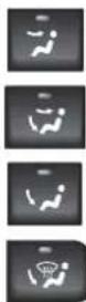
If ventilation is required with the system off, press the desired manual air distribution button. This will provide unconditioned air only when the vehicle is moving.
Note: Heated screen and external temperature display functions can be selected when the system is switched off.
Operating Tips
Hot Weather Operating Tips
If the vehicle has been parked in the sun the interior will cool faster if you follow these guidelines.
a) Before entering the vehicle, leave the doors open for a short time to allow the excessively hot air to escape.
b) Drive for a short time with the windows open to force hot air from the car.
Cold Weather Operating Tips
Avoid driving with the air conditioning system off or in manual air recirculation for prolonged periods in cold weather. Humidity may build up inside the vehicle and screen misting could possibly occur.
E - Heating, Ventilation & Air-Conditioning
Air Distribution
The illustration below shows the location of the air vents in the vehicle.
Air distribution is automatically controlled when AUTO is selected. Manual control can be achieved using the air distribution buttons.
Airflow from the fascia vents can be regulated or switched off using the thumbwheel controls on those vents. The airflow through these vents may be directed by the adjustable vanes.
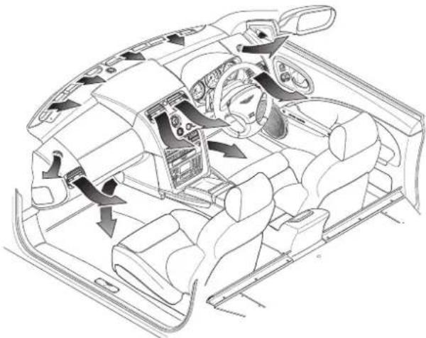
natural_image
Interior view of a car cockpit with steering wheel, dashboard, and air vent (no text or symbols)System Fault Display
The air conditioning system is equipped with self diagnostics.
If a fault is detected, the symbol 'Er' will appear in the display accompanied by a series of 'beeps' for 5 seconds. In this unlikely event the vehicle should be returned to the Aston Martin dealer at the earliest convenience.
'Er' will be displayed on each subsequent vehicle start until the fault is rectified.
Contents
Security Systems 1-F-2
System Operation - Using the Ignition Key 1-F-3
System Operation - Using the Key Fob 1-F-4
Key Fob Time-Out 1-F-4
Unlocking the Car, Disarming the Alarm 1-F-5
Locking the Car, Arming the Alarm 1-F-5
Deadlocking the Car (Not North America) 1-F-6
Alarm and Security System Protection 1-F-6
Full Alarm Activation 1-F-6
Panic Alarm (Where enabled) 1-F-7
Boot (Trunk) Lock Control 1-F-7
The Passive Anti-Theft System (PATs) 1-F-8
Starting the Engine 1-F-8
PATs Status 1-F-9
Alarm Key Fob - Range and Battery Replacement 1-F-10
Security Systems
The primary protection for your V12 Vanquish is provided by an electronic security system. Protection is further enhanced by a passive anti-theft system (PATS) which provides engine immobilisation measures if the wrong ignition key is used. The total system has the following functions:
- Remote Arming/Disarming via a Key Fob.
- P erimeter Sensing via switches on the doors, boot lid and bonnet.
- Boot Release on the Key Fob.
- P anic Alarm triggered using the Alarm Key Fob.
- Alarm Siren with battery back-up (in markets where audible sirens are permitted).
- Random Code Encryption to prevent electronic scanning or grabbing of the key fob identity code.
- Glass break sensor
• P assive Anti-Theft system.
• 3 way immobilisation
The Tracker System (Optional - Mainland UK only)
The Tracker hardware is fitted as standard to UK cars only and may be activated for any owners who wish to subscribe to this additional vehicle security system. Please consult your dealer for system details and subscription rates.
System Operation - Using the Ignition Key
To Lock the Car and Set the Alarm
Turn the key towards the front of the vehicle and release. The direction indicators will flash and a sound will be heard. The driver and passenger doors, and the trunk will lock and the alarm will be set.
Window Closing
Warning: Check that all persons are clear of the windows before using this function. Give a verbal warning to ensure that all persons in the vicinity are aware of the danger of trapped hands, etc.
As you lock the car, hold the key in the 'Lock' position to close any open windows.
Unlocking the Car
Turn the key towards the rear of the car. This will unlock all doors and the trunk. The alarm system will be disarmed.
Window Opening
If, during unlocking, the key is held in the unlock position the door windows will lower to the maximum down position.
System Operation - Using the Key Fob
Key Fob Time-Out
If the car is not used for 28 days, the key fob sensing circuits will switch off to conserve battery power. The doors may not then be opened with the key fob. Open either door with the ignition key to reactivate the sensor circuits, the key fob will then work normally.
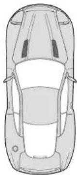
natural_image
Top-down line drawing of a car viewed from the side (no text or symbols)The system is normally controlled using the four button key fob.
The upper left (lock symbol) button controls the normal locking of the car and arms the alarm system.
The upper right (unlock symbol) button unlocks the car and disarms the alarm system.
The lower left (headlamp symbol) button activates the exit illumination function.
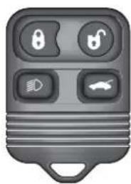
natural_image
Gray remote control key with four function buttons (boot, lock, display, car) and no visible text or symbolsThe lower right button provides independent control for the boot lock.
The Panic Alarm feature is operated using the lower left (headlamp symbol) key fob button.
The security system aerial is located below the rear windscreen. The normal operating range of the key fob is approximately 10 metres (30 feet).
Unlocking the Car, Disarming the Alarm

Approach within 10 metres (30 feet) of the car, point the key fob towards the rear windscreen and press the unlock button once. The following events will occur:
-
The car doors will unlock.
-
The direction indicators will flash (in markets where visible alarm signals are permitted and programmed).
-
The alarm system will be switched off.
Locking the Car, Arming the Alarm

Approach within 10 metres (30 feet) of the car, point the key fob towards the rear windscreen and press the lock button. The following events will occur:
- The car doors will lock.
- The direction indicators will flash once (in markets where visible alarm signals are permitted).
- The alarm system will be switched on.
Caution: If the car is locked and the alarm is set with the windows open, False alarms may be triggered by external noises triggering the glass break sensor.
Deadlocking the Car (Not North America)
To deadlock the car, press the keyfob lock button twice within three seconds. Both outer and inner door handles will be totally disabled.
Warning: When the vehicle is deadlocked, the doors cannot be opened, either from the outside or inside, except with the correct key fob transmitter. Therefore, deadlocking should not be used when persons are inside the vehicle as they will be locked in and will be unable to release themselves.
Caution: If the Battery Disconnect Switch is actuated when deadlocking is engaged, access to the vehicle will be lost. Activating the Battery Disconnect Switch also deactivates the security system and renders the key fob inoperative. Deadlocking cannot then be disengaged using the ignition key.
Alarm and Security System Protection
With the alarm system armed, any attempt to forcibly open a door, the boot or the bonnet will result in full alarm activation.
The alarm will also be fully activated if a window is broken (glass break sensor).
(See also the engine immobilisation protection afforded by the PATs system)
Full Alarm Activation
When activated, the siren sounds for 30 seconds (in markets where audible sirens are permitted) and the direction indicators flash (in markets where visible alarm signals are permitted). After 5 minutes the alarm stops (i.e. the direction indicators stop flashing) and returns to the armed state. The doors and boot remain locked throughout.
The alarm can be deactivated by pressing the upper left (lock) button on the key fob. This will also disarm the alarm and unlock the doors.
Panic Alarm (Where enabled)
Note: The Panic Alarm feature is not enabled for all markets
The system has a panic alarm feature which can be activated whatever the alarm state. This feature may be used to discourage offenders when you are either inside the car or within the operating range of the alarm key fob (approximately 10 metres / 30 feet).

To activate the panic alarm, press the lower left (headlamp) button three times within three seconds. The system will enter the full alarm state.
Turn the ignition key to position II to stop the panic alarm and return to the state prior to initial panic alarm activation.
If the panic alarm is not switched off using the ignition key, the siren will stop after 30 seconds and the indicator flashing will deactivate after 5 minutes.
Boot (Trunk) Lock Control
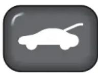
To open the boot (trunk), press the lower right key fob button. The boot will unlock. The alarm system will remain armed for the doors and bonnet. It is not necessary to disarm the alarm in order to use the boot unlock feature.
Caution: Always ensure that the boot (trunk) lid is securely closed after use. The boot (trunk) interior lights will remain on for several minutes if the lid is left partially open.
The Passive Anti-Theft System (PATs)
The PATs system is a fully automatic engine immobiliser. The system consists of a transponder inside the head of each ignition key and, around the ignition lock, a transceiver aerial which communicates signals to the PATs electronic control unit. The PATs control unit communicates with the engine management controller to immobilise the engine until a valid code signal is received from the ignition key.
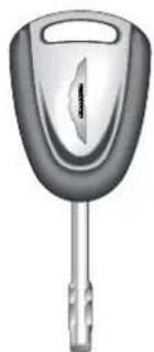
natural_image
Illustration of a car key with a handle and spout (no text or symbols)Two coded keys are provided with the vehicle. These keys fit both the door locks and the ignition lock.
In the event of loss of one of the keys, duplicate keys can be created and programmed from the other key by your Aston Martin Dealer.
Starting the Engine
When the alarm system is disarmed and the vehicle key is turned in the ignition lock, the PATs controller sends a signal to the ignition key. The ignition key must respond with a valid key code before engine start will be enabled. If a valid code is received, the ignition system will operate normally.
If the key code is not received, or is invalid, engine start remains disabled.
Caution: To ensure a trouble-free signal exchange between the key and the vehicle, do not cover the key head with any metal object (e.g. metal key tags or another key).
PATs Status
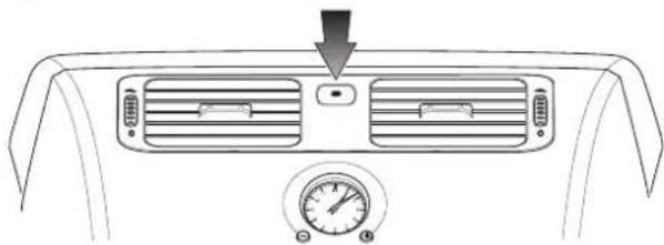
natural_image
Top-down view of a car air conditioning unit with ventilation grilles and a pressure gauge (no text or symbols)The PATs system state is shown by the red status lamp between the centre console air outlets.
The status lamp will illuminate for three seconds when the ignition is turned on and will extinguish when a valid code is received from the ignition key.
When the ignition is turned off, the status lamp will flash. This is the normal state when the vehicle is parked with the ignition off and the key removed.
If the status lamp remains on when the ignition is switched on, the system is in fail-safe mode. This means that the car will start, but PATs has a fault.
After one minute, the status lamp will flash a fault code. Your Aston Martin Dealer can use this code to aid diagnosis of the PATs problem.
If the status lamp continues flashing when the ignition is turned on, the vehicle remains immobilised due to a fault in the system or an invalid key code. Should this situation arise, try the other ignition key. If successful, source a replacement for the faulty key. If problems persist with both ignition keys, consult your Aston Martin Dealer.
During normal operation, the only indication that PATs is present is the PATS status lamp. The system is designed to be completely transparent to the vehicle user.
Alarm Key Fob - Range and Battery Replacement
The normal range of the alarm key fob is approximately 10 metres (30 feet). If you need to come closer to the car before the key fob signal is effective, the key fob battery probably needs replacing.
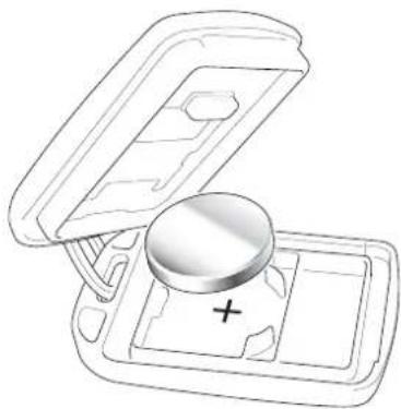
natural_image
Line drawing of a device with an open lid and a plus button, no text or symbols presentCaution: To avoid disrupting the coding of the key fob transmitter during battery renewal, the operating buttons must not be pressed. If coding is disrupted, it will be necessary to have your Aston Martin dealer re-programme the key fob transmitters.
To replace the key fob battery, open the battery compartment using a small flat bladed tool and remove the cover.
Lift out the battery noting the correct orientation (positive terminal downwards). Take care not to damage the upper electrical contacts in the battery compartment.
Fit a replacement battery (One x CR2032 three volt battery), observing the correct polarity (+ve side down). Refit the battery compartment cover and press the outer end to engage the cover lock tab.
Test that the alarm system will arm/disarm when actuated using the key fob from a range of approximately 10 metres (30 feet).
Contents
Introduction 1-G-3
Owner Maintenance 1-G-3
Electronic Fuel Injection 1-G-3
Parts and Lubricants 1-G-4
Emission Warranty 1-G-4
Engine Compartment Covers 1-G-4
Servicing Precautions 1-G-5
Dangerous Substances 1-G-6
Engine Oils 1-G-6
Protect The Environment 1-G-6
Fuel Tank Filling 1-G-6
The V12 Vanquish Boot (Trunk) 1-G-7
Fluid Level Checks 1-G-8
Engine Oil Level Check 1-G-9
Engine Coolant Level Check 1-G-10
Power Steering Fluid Level Check 1-G-11
Brake Fluid Reservoir 1-G-12
Windscreen Wash Fluid Level Check 1-G-13
Wheels and Tyres 1-G-15
Tyre Pressures 1-G-15
Running-In New Tyres 1-G-16
Tyre Service 1-G-16
Tread Wear Indicators 1-G-17
Winter Tyres 1-G-17
United States Department of Transportation 1-G-18
Tyre Inflation Aerosols 1-G-20
Transporting and Towing 1-G-21
Selecting Neutral 1-G-22
Towing 1-G-22
Electrics - Battery 1-G-22
Battery Warnings - Gulf States 1-G-23
Quiescent Battery Drain 1-G-24
The Battery Disconnect Switch 1-G-24
The Battery Reconnect Switch 1-G-25
Battery Conditioner 1-G-25
Sequence for isolating/reconnecting the battery 1-G-26
Electrical Start from Another Vehicle 1-G-28
Jump Start Procedure 1-G-28
Engine Block Heating (Canadian and Swedish Cars) 1-G-29
Fuse Boxes (RH drive illustrated) 1-G-30
Bulb and Fuse Replacement 1-G-37
Headlight Main and Dipped Beam 1-G-38
Front Indicator / Front Fog / Front Parking Lights 1-G-39
Side Marker Lights 1-G-40
Rear Lights - (Indicators, Stop/Tail, Reverse, Rear Fog) 1-G-41
Number Plate Lights 1-G-42
Rear Interior Quarter Lights 1-G-43
Front Interior Lights 1-G-44
Headlamp Ventilation 1-G-44
Bodywork and Fittings 1-G-45
Checks and Maintenance 1-G-45
Paintwork 1-G-45
Vehicle Cleaning 1-G-46
Upholstery, Carpets and Seats 1-G-47
Care and Maintenance of Seat Belts 1-G-48
Underbonnet Cleaning 1-G-48
Storing the Car - Recommendations 1-G-49
Extended Storage 1-G-50
Recommissioning After Storage 1-G-51
Date of Manufacture Information (Australia only) 1-G-52
Introduction
Owner Maintenance
Each item in the Service Schedules must be performed on time as failure to do so may void the New Car Warranty or other warranties. It is the owner's responsibility to see that the vehicle is maintained properly and in accordance with the manufacturer's service schedules.
Due to the sophistication of the various systems and the specialised equipment required to maintain the V12 Vanquish, owner maintenance should be restricted to the routine procedures given in this Owner's Guide. If you think that the car is not functioning properly, please return it to an Aston Martin Dealer to be checked professionally.
Electronic Fuel Injection
WARNING: Electronic Fuel Injection: If the fuel system is allowed to run dry irreparable damage to the fuel pumps may occur.
The electronic fuel injection system requires special equipment and test facilities to set up and maintain so that the car gives maximum performance coupled with economy, reliability and safe vehicle emissions. You are, therefore, strongly advised to entrust all service work to an Aston Martin Dealer.
WARNING: Any modifications/additions to the fuel system not specifically designed by Aston Martin are prohibited. If carried out, they may cause damage to the fuel system which in some circumstances could result in fire. It is recommended that all Service Action Campaigns are entrusted to an Aston Martin Dealer.
Parts and Lubricants
When undertaking a warranted servicing task, only parts, materials, lubricants etc. that are specifically recommended by Aston Martin Lagonda Limited should be used. Failure to do so can result in damage to the vehicle and invalidate the New Car Warranty or other warranties. Recommended lubricants, capacities, etc. may be found in the Specifications section of this Owner's Guide, and are recommended for use at all routine services whether or not under warranty.
Emission Warranty
The emission control systems fitted to cars for certain markets are covered by a separate warranty. A statement of the provisions is given in the Warranty section of this Owner's Guide. You are advised to familiarise yourself with all warranty conditions at the earliest opportunity after taking delivery of your car.
Engine Compartment Covers
The primary fluid level checks and reservoirs within the engine compartment are all immediately accessible.
The less frequently maintained items are located under the engine compartment side covers. These items will be maintained by your Aston Martin Dealer during regular vehicle service.
Servicing Precautions
To avoid personal injury, the following safety precautions must be observed when the bonnet is open and the engine is running or the ignition is switched on.
WARNINGS:
Keep hands, hair, tools, items of clothing and jewellery clear of all drive belts, pulleys and operating mechanisms. The cooling fans may operate even though the engine is not running. The windscreen wiper mechanism is fitted with an intermittent delay facility and may operate unexpectedly if left switched on.
Exhaust fumes contain carbon monoxide. Carbon monoxide is a dangerous gas and can cause unconsciousness and may be fatal. Do not breathe exhaust gas as it contains carbon monoxide which by itself has no colour or odour. Never start or leave the engine running in an enclosed, unventilated area.
Avoid skin contact with all exhaust system and engine components, engine fluids and escaping steam. They may be hot and will burn you.
Whenever possible work in the engine compartment with the engine cool, the ignition switched off and the battery disconnected.
Do not work beneath the car with a vehicle lifting jack as the only support. Place suitable stands under the car.
Keep children and pets clear of the car. Do not allow anyone inside the car unless specifically working to your instructions.
Protect yourself against dangerous substances (see 'Dangerous Substances' on the following page).
Dangerous Substances
WARNING: Many liquids and other substances used in motor vehicles are poisonous and should under no circumstances be consumed and should, so far as possible, be kept from contact with the skin. These substances include battery electrolyte, antifreeze, oil, brake and clutch fluid, petrol, windscreen washer additives, lubricants, refrigerant and various adhesives. Particular care should be taken to avoid unnecessary contact with used engine oil. Always read carefully the instructions printed on labels or stamped on components and follow them carefully. Such instructions are included for reasons of your health and personal safety. Never disregard them. Dangerous substances should be kept out of reach of children.
Engine Oils
WARNING: Prolonged and repeated contact with used engine oils can cause serious skin disorders, including dermatitis and cancer. Avoid excessive contact, wash thoroughly after contact. Keep out of reach of children. When your oil is changed, be sure that it is done by an experienced person. In addition, observe all laws regarding the disposal of waste oil and toxic fluids.
Protect The Environment
WARNING: It is illegal to pollute drains, water courses, or soil. Use authorised waste disposal facilities, including civic amenity sites and garages providing facilities for receipt of used oil. If in doubt, contact your local authority for advice.
Fuel Tank Filling
WARNING: Petrol is highly flammable and, in confined spaces, is also explosive and toxic. In the event of spillage, switch off the engine, use no naked flame or light. Do not smoke. Do not inhale fumes.
The V12 Vanquish Boot (Trunk)
The following items of maintenance/safety equipment are stored in the boot (trunk):
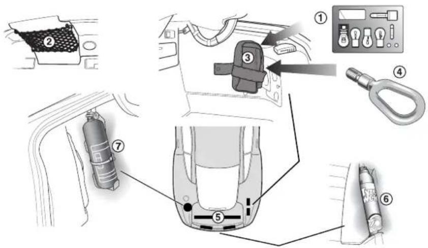
- Bulb Kit 2. Owner's Guide
- First Aid Kit 4. Towing Eye
- Warning Triangle 5. Umbrella
- Tyre Inflation Aerosols 7. Fire Extinguisher (Optional)
Notes: Item 5 indicates equipment stored in the boot (trunk) lid. The warning triangle is not fitted to North American cars.
Fluid Level Checks
Engine Bay Component Location (Right Hand Drive Illustrated)
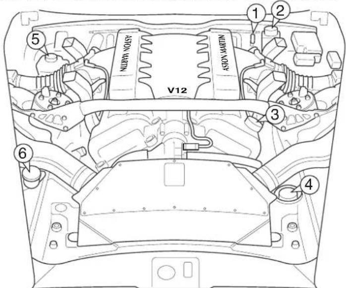
1 Engine Oil Dipstick 2 Engine Coolant Header Tank
3 Engine Oil Filler Cap 4 Power Steering Fluid Reservoir
5 B r ake Fluid Reservoir 6 Washer Fluid Reservoir
Note: Item 5 changes sides for left and right hand drive.
In the following descriptions, numbers in parenthesis, e.g. (1), refer to the numbered items in the diagram and list above.
All directions are described as viewed from the driver's seat. Thus the oil filler cap (item 3) is on the left side of the car, the washer fluid reservoir (item 6) is normally on the right side of the car.
Engine Oil Level Check
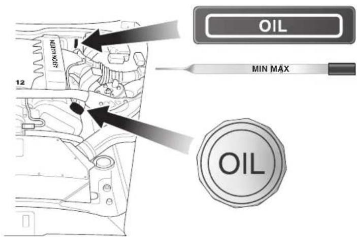
When checking engine oil level, the car should be on level ground. If the engine has been running immediately prior to the check, wait several minutes after stopping the engine for the oil to drain back into the sump. The dipstick (1) is located on the left-hand side of the engine (the dipstick should be wiped clean using a lint free cloth before checking the oil level). The oil level should be maintained at the 'Max' dipstick mark.
Approximately one litre is required to bring the level from Min to Max. The recommended engine oil should be added through the oil filler cap (3). Do not overfill. Replace the filler cap securely.
WARNING: Running the engine with insufficient oil can cause serious damage.
To avoid personal injury and before working in or near the engine compartment, switch off the engine and let it cool. Engine components are hot and may cause severe burns. See also the warnings given in SERVICING PRECAUTIONS.
Engine Coolant Level Check
The engine coolant header tank (2) is mounted on the right-hand corner of the engine bulkhead. It is fitted with a pressure relief cap which should not be removed unless the engine is cold. A thick cloth or glove must be placed over the cap and the cap turned slowly in an anticlockwise direction.
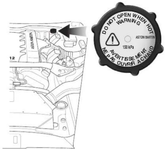
Allow any residual pressure to slowly drop and then continue to turn the cap until it is released from the header tank. Lift the cap clear and top up the tank with an antifreeze mixture, of the correct strength, up to the maximum mark on the side of the tank (see 'Specifications').
WARNING: Scalding can be caused by escaping steam or coolant. DO NOT remove the pressure relief cap until the system is cold. In addition, use a cloth or glove to protect hands. Protect your face and arms adequately. See warnings given in SERVICING PRECAUTIONS.
Power Steering Fluid Level Check
The power steering pump reservoir (4) is situated in the left front corner of the engine compartment.
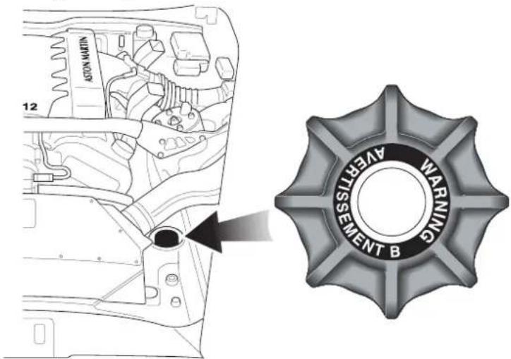
The reservoir level should be checked when the engine is cold. The reservoir cap incorporates a dipstick. Top up the reservoir with clean fluid of the recommended grade up to the lower mark on the dipstick. DO NOT OVERFILL.
WARNING: Avoid touching the sides of the engine when working in the engine compartment. The exhaust system will be hot if the engine has recently been run.
Caution: Take care that hydraulic fluid does not contact the paint work during the topping up operation. Serious paint work damage can result. If a spillage does occur, immediately flush the hydraulic fluid from the paint work with clean, fresh water and then wipe with a clean damp cloth.
Brake Fluid Reservoir
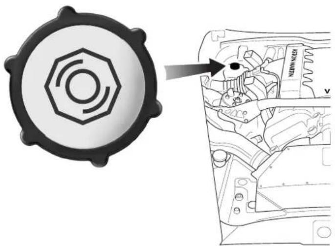
natural_image
Technical diagram showing a gear-like component with an arrow pointing to a mechanical assembly (no text or symbols present)The brake fluid reservoir (5) is fitted to the driver's side of the engine compartment on top of the brake master cylinder assembly.
Before removing the cap, clean the cap and the surrounding area thoroughly to prevent ingress of dirt and foreign matter. Top up to the indicated level on the reservoir with the recommended brake fluid (see 'Specifications') and refit the cap securely.
Brake fluid will absorb water vapour and must be replaced every two years in order to maintain the efficiency of the hydraulic system.
WARNINGS: Do not drive the vehicle if the brake fluid level is low. Use only new DOT4 brake fluid from air tight containers.
Caution: Take care that hydraulic fluid does not contact the paint work during the topping-up operation. Serious paint work damage can result. If a spillage does occur, immediately flush any hydraulic fluid from the paint work with clean, fresh water and then wipe with a clean damp cloth.
Windscreen Wash Fluid Level Check
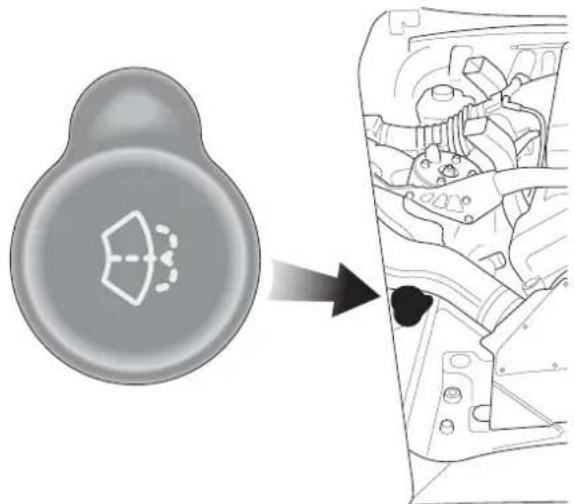
natural_image
Diagram showing a car interior with a circular component and a magnified view of internal components (no text or symbols)The windscreen washer fluid filler cap (6) is situated in the right front corner of the engine bay and should be topped up as required with the correct concentration of screen wash solution (see the manufacturers recommendations on the screen wash fluid container). When the level of screen wash fluid is low the instrument panel warning light will illuminate.
In winter, increase the concentration of screen wash to prevent freezing of the washer fluid.
Caution: State or local regulations may restrict the use of volatile organic compounds (VOCs), which are commonly used as anti-freeze agents in washer fluid. A washer fluid with limited VOC content should be used only if it provides adequate freeze resistance for all regions and climates in which the vehicle will be operated.
Warning: If you operate your vehicle in temperatures below 40^ F, use washer fluid with anti-freeze protection. In cold weather, failure to use washer fluid with anti-freeze protection could result in impaired windscreen vision and increase the risk of a vehicle crash.
Windscreen Washer Jets
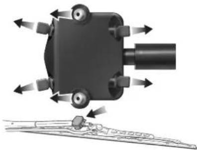
natural_image
Mechanical assembly diagram showing a rotating component with directional arrows indicating motion (no text or symbols)A washer jet housing is located on each of the two windscreen wiper arms. Each housing contains six washer jets.
Adjust the angle of the centre jets if necessary using a fine needle so that fluid covers the full length of both sides of the wiper blades and all spray stays on the windscreen.
Wheels and Tyres
The tyres detailed in the specification section of this Owner's Guide are the only tyres approved for use on this vehicle.
To maintain the high performance capability of the car, specified tyres should be fitted when replacement becomes necessary. The recommended tyres for V12 Vanquish are unidirectional. Tyre sizes are different on the front and rear axles. Therefore, complete wheels cannot be swapped from one side of the vehicle to the other or between axles.
It is a characteristic of high performance tyres that temporary 'flat spots' may develop if the vehicle is left standing in high or low ambient temperatures for any length of time. These 'flat spots will manifest themselves as minor vibrations when the car is first driven from cold. As the tyres warm up to operating temperature, the normal tyre shape should be restored and the vibrations cease. If vibrations persist, consult your Aston Martin Dealer.
Tyre Pressures
In the interest of safety and tyre life it is important that correct tyre pressures are carefully maintained (See 'Specifications').
Road holding, steering, braking and tyre wear are especially vulnerable to incorrect tyre pressures.
Pressures increase slightly when tyres are hot and, for an accurate reading, pressures should be checked when the tyres are cold.
Check the instrument panel tyre pressure monitor lamp regularly before starting your journey. Reinflate any tyre with a low pressure at the earliest opportunity.
After adjusting the tyre pressures, ensure that the valve caps are securely replaced to provide an additional air seal and to prevent the ingress of dirt.
Running-In New Tyres
When new tyres have been fitted, speed should be limited, particularly during the first 80 km (50 miles) or so of driving. Fast cornering, hard braking, and harsh acceleration should also be avoided during this period.
Tyre Service
The recommended tyres for V12 Vanquish are unidirectional and must be fitted to the rims with the arrow pointing in the direction of forward rotation.
Tyres should be examined at regular intervals for wear and damage. Stones or other objects which have become lodged in the tyre treads should be carefully removed.
When new tyres are required, it is advisable to consult an Aston Martin Dealer who will be able to supply tyres to the correct specification.
Only fit the specified tyres. These are designed for the potential speed, acceleration, handling and braking performance of the car
New tyres should not be fitted to the front wheels in combination with worn rear tyres as rear end stability will be affected. Consult your Aston Martin Dealer for advice if the rear tyres are also worn.
Each wheel and tyre unit must be balanced dynamically to ensure efficient steering, optimum tyre wear and maximum ride comfort. Because of the potentially high speeds, it is essential that wheel balancing is carried out when new tyres are fitted.
WARNING: Because of the high performance potential of your V12 Vanquish, Aston Martin strongly recommend replacement of any damaged or worn tyre.
Tread Wear Indicators
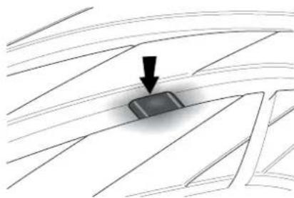
natural_image
Diagram showing a dark object on a grid surface with an arrow pointing downward (no text or symbols)Tread wear indicators are incorporated into the construction of all tyres. These indicators are integral moulded ribs spaced at regular intervals around the circumference of the tyre and extend across the full width of the tread, in all primary grooves.
When a tyre has worn causing one or more of the indicators to be flush with the outer face of the tread, only 1.6mm (0.062in) or less tread depth remains and the tyre has reached its wear limit. It then becomes illegal in certain countries and must be replaced.
Winter Tyres
Two options are available to equip your V12 Vanquish for winter motoring.
Snow Tyres - The recommended snow tyres will not fit the regular wheel rims. Four special wheel rims and winter tyres are required to fully equip the car for severe weather driving. (See the Specifications section of this Owner's Guide).
Snow Chains - These are available from your Aston Martin Dealer for temporary use when driving in heavy snow conditions. Snow chains should only be fitted to the rear (driving) wheels.
United States Department of Transportation
(see tyre grades in the 'Specifications' section
Uniform Tyre Quality Grades
The following information relates to the tyre grading system developed by the National Highway Traffic Safety Administration which will grade tyres by tread wear, traction and temperature performance.
All passenger car tyres must conform to federal safety requirements in addition to these grades.
Treadwear
The treadwear grade is a comparative rating based on the wear rate of the tyre when tested under controlled conditions on a specified government test course. For example, a tyre graded 150 would wear one and a half times as well on the government course as a tyre graded 100. The relative performance of tyres depends upon the actual conditions of their use, however, and may depart significantly from the norm due to variations in driving habits, service practices and differences in road characteristics and climate.
Traction - A, B, C
The traction grades, from the highest to the lowest are A, B and C, and they represent the tyre's ability to stop on wet pavement as measured under controlled conditions on specified government test surfaces of asphalt and concrete. A tyre marked 'C' may have poor traction performance.
WARNING: The traction grade assigned to this tyre is based on braking (straight ahead) traction tests and does not include cornering (turning) traction.
Temperature - A, B, C
The temperature grades are 'A' (the highest), 'B' and 'C' representing the tyres resistance to the generation of heat and its ability to dissipate heat when tested under controlled conditions on a specified indoor laboratory test wheel. Sustained high temperature can cause the material of the tyre to degenerate and reduce tyre life, and excessive temperature can lead to sudden tyre failure.
The grade 'C' corresponds to a level of performance which all passenger car tyres must meet under the Federal Motor Vehicle Safety Standard No. 109.
Grades 'B' and 'A' represent higher levels of performance on the laboratory test wheel than the minimum required by law.
WARNING:
The temperature grade for this tyre is established for a tyre that is properly inflated and not overloaded. Excessive speed, under-inflation or excessive loading, either separately or in combination, can cause heat build-up and possible tyre failure.
Tyre Inflation Aerosols
Your V12 Vanquish is equipped with two tyre inflation aerosols located in the rear wall of the boot. In the event of a simple puncture, use the following procedure to perform a safe temporary reinflation of the tyre.
Warning: Major tyre damage cannot be repaired using the inflation aerosols. A replacement tyre MUST be fitted at the earliest opportunity. This is particularly important because of the high performance potential of V12 Vanquish. Do not exceed 50 kph (30mph) when a temporarily repaired tyre is in use.
-
Move the vehicle to a safe location. Remove the object causing the puncture. Position the valve of the punctured tyre at the bottom.
-
Shake both tyre inflation aerosols. Warm the aerosols if the temperature is below freezing.
-
Firmly screw the tube of the inflation aerosol to the valve of the punctured tyre. Remove the protective cap from the canister and, holding the canister upright, press the button until the complete contents of the canister are injected into the punctured tyre. Repeat this step with the second canister.
-
Fit the small warning label to the tyre and the large warning label to the steering wheel. Read the warning labels.
-
Drive off immediately for 3-6 km (2-4 miles) at a maximum speed of 50 kph (30 mph).
-
Stop in a safe place and visually inspect the tyre to confirm that the leak has been successfully sealed. Drive to the nearest service station and adjust the tyre pressure to specification.
-
Limit your speed to 50 kph (30 mph) and have the defective tyre, valve and pressure sensor replaced within 320 km (200 miles).
-
Purchase replacement aerosols as soon as possible from your Aston Martin Dealer.
Caution: The tyre pressure sensor must be replaced after using a tyre inflation aerosol.
Transporting and Towing
The recommended method for moving a defective vehicle is to have it carried in a purpose built covered vehicle transporter.
The front towing eye is only for emergency use when moving the vehicle for short distances, e.g. If it is causing an obstruction or if it requires winching onto a transporter.
If moving your V12 Vanquish in such a situation, remove the towing eye access plug in the grille. Remove the towing eye from its storage location in the right side of the boot. Fit the towing eye to the stud through the centre of the front grille aperture.
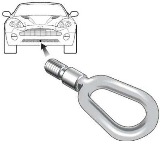
natural_image
Illustration of a car head with a metallic chain link attached to its side, showing the impact of a sensor or sensor device (no text or symbols present)Caution: Protect the vehicle paintwork when fitting the towing eye.
The V12 Vanquish may then be towed using a rope, provided that the precautions on the following page are observed:
Selecting Neutral
Turn on the ignition. Select Neutral by pulling both paddles twice. This will leave the transmission in neutral when the ignition is switched off.
Turn the key to position I (ignition off, steering unlocked).
Towing
Use the handbrake or foot brake very gently as necessary during towing to prevent excessive slack in the tow rope.
WARNING: Remember that neither power braking nor power steering are available with the engine turned off. Substantially higher brake pedal pressures and steering effort are required.
If a transmission fault is present, your vehicle must be transported.
Electrics - Battery
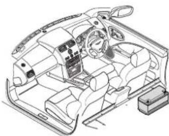
natural_image
Line drawing of a car interior showing dashboard, steering wheel, and seat (no text or symbols)The battery is fitted to the right-hand side of the car in the rear of the passenger compartment. The battery is maintenance free and should only require checking by your dealer during regular vehicle services.
Battery charge level must be maintained by use of the battery conditioner if the vehicle is not in frequent use.
Caution: The engine must never be run with the battery disconnected.
WARNINGS:
Battery posts, terminals and related accessories contain lead and lead compounds. Wash hands after handling.
The battery emits combustible gas (hydrogen) when charging. Avoid sparks and short circuits by switching off the charger before connecting or disconnecting the charger at the battery.
Do not ingest battery acid. If battery acid is ingested, drink large quantities of water or milk followed by milk of magnesia, beaten egg or vegetable oil. Call for medical assistance immediately.
Do not let battery acid come into contact with skin, eyes, hair, fabric or painted surfaces. A solution of warm soapy water and baking soda may help neutralise acid.
Used batteries contain sulphuric acid, lead and other potentially hazardous materials. Dispose of unwanted batteries in authorised waste disposal facilities. DO NOT discard unwanted batteries in household waste.
Battery Warnings - Gulf States
DANGER/POISON

SHIEI EYES
EXPLOSIVE
GASES CAN CAUSE
BLINDNESS OR INJURY

NO
• SPARKS
• FLAMES
• SMOKING

SULFURIC ACID
CAN CAUSE
BLINDNESS OR
SEVERE BURNS
FLUSH EYES IMMEDIATELY WITH WATER

GET MEDICAL
HELP FAST
KEEP OUT OF THE REACH OF CHILDREN DO NOT TIP: KEEP VENT CAPS TIGHT AND LEVEL
- No Naked Flames
- Corrosive
- Wear Eye Protection
- Read Safety Warnings
- Keep out of reach of children
- Explosive Gasses


2
4
6
Quiescent Battery Drain
Any power drain from a battery after the ignition is switched off is referred to as quiescent battery drain. V12 Vanquish, in common with many modern, high technology motor cars, contains electronic circuits and sub-systems which must be left activated at all times. For example, the clock, security systems and in-car entertainment system continue to drain battery power even with the ignition switched off. This quiescent drain will discharge a fully charged new battery in approximately 30 days unless recharged by normal engine running or an independent battery charger.
It is therefore vital that, when leaving your car unused for extended periods, you use the battery disconnect switch to reduce quiescent drain to a minimum and that you use the battery conditioner to maintain battery charge level.
The Battery Disconnect Switch
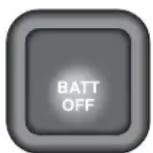
The battery disconnect switch is located in the right front corner of the trunk. When actuated, power to all control modules is disconnected and only 'keep alive memory' power is maintained. Thus the quiescent power drain on the battery is greatly reduced.
To conserve battery power, press this switch whenever the vehicle is to be out of use for some days. To prevent the alarm from sounding, disconnect the battery within 10 seconds of switching off the ignition.
If the battery disconnect function is used in conjunction with the battery conditioner, the vehicle may be stored for many months without additional battery maintenance.
Warning: Never disconnect the Battery Disconnect Switch when the engine is running.
Warning: The vehicle alarm systems will be disabled when the battery disconnect switch is used. The vehicle will be secured only by the mechanical door locks. Ensure that the vehicle is parked in a secure location.
The Battery Reconnect Switch
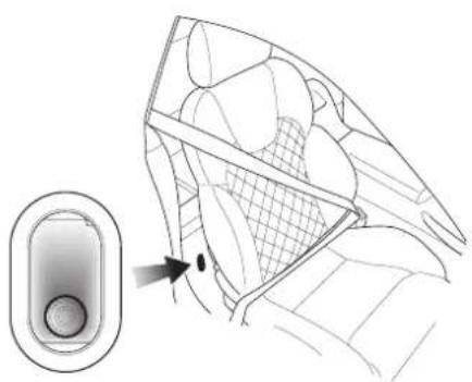
natural_image
Diagram of a car interior showing a hand cursor pointing to the window, with no visible text or symbols.Press the battery reconnect switch in the right hand rear heelboard to reconnect the battery before attempting to start the vehicle.
All vehicle electrical systems (except 'keep alive memory') are disabled until this switch is pressed.
Caution: Do not use the battery disconnect switch when the car is locked and the alarm is armed. To do this will cause the alarm system to activate.
Battery Conditioner
The automatic battery conditioner supplied with V12 Vanquish is suitable for use on all types of 12 volt lead acid batteries.
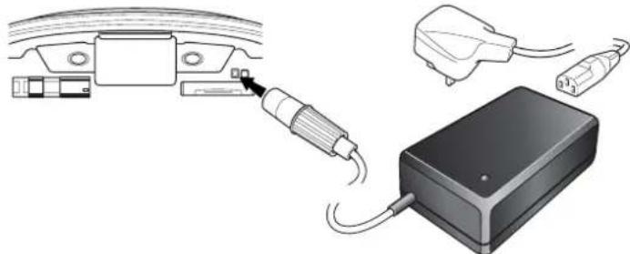
natural_image
Diagram showing cable connections to a device with plug and cable outlet (no text or symbols)Warnings: For indoor use only.
Disconnect the mains supply before making or breaking battery connections.
Warnings: (Battery Conditioner warnings - continued).
Explosive gasses are given off by batteries during charging. Prevent flames and sparks - No smoking.
Do not attempt to start the vehicle with the charger connected to the mains supply.
The conditioner has an inbuilt mains connector appropriate for the market in which the vehicle is sold.
The conditioner output is 13.8V - 14.7V, up to 2.7A. It is designed for conditioning of partially or fully charged batteries. It will not effectively charge a deeply discharged battery.
The unit has an electronic controller which senses when the battery charge level becomes low and commences charging at 14.7 volts. When the battery charge level rises to 80%, a 2 hour timer starts. The unit continues charging for a further 2 hours until the battery is 100% charged and then reduces the charge voltage to 13.8 volts to maintain a small trickle charge to keep the battery in a fully charged state. The conditioner may be left in this state indefinitely.
Sequence for isolating/reconnecting the battery
Warning: The vehicle security systems will be disabled when the battery disconnect switch is used. The vehicle will be secured only by the mechanical door locks. Store the car in a secure location.
Caution: If the Battery Disconnect Switch is actuated when deadlocking is engaged, access to the vehicle will be lost. Activating the Battery Disconnect Switch also deactivates the security system and renders the key fob inoperative. Deadlocking cannot then be disengaged using the ignition key.
Disconnecting the Battery
a. Switch off the engine and apply the handbrake.
b. Remove the ignition key and exit from the car.
c. Open the boot with the boot open switch or press the boot open key on the key fob.
d. Press the battery disconnect switch.
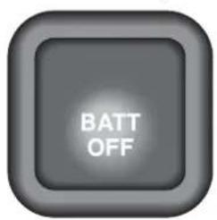
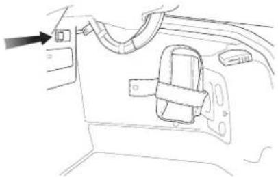
natural_image
Line drawing of a car interior showing a door, seatbelt, and cable (no text or symbols)e. Connect and switch on the battery conditioner.
f. Gently close but do not latch the boot lid (Danger of damage to the boot water seal from the battery conditioner power cable).
Reconnecting the Battery
a. When you wish to use the vehicle, disconnect the conditioner from the mains supply before disconnecting from the vehicle socket.
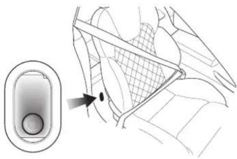
natural_image
Diagram showing a device with a button and a magnified view of the interior panel (no text or symbols)b.Firmly press the battery reconnect switch until it latches to return the power circuits to their normal condition.
Electrical Start from Another Vehicle
For Re-Charge of Recoverable Batteries Only
Warning: Under no circumstances must the V12 Vanquish be driven if the vehicle battery is incapable of starting the engine. In this case the battery must be recharged or replaced.
If your V12 Vanquish will not start due to a discharged battery, it may be started by connecting the battery from another vehicle to the V12 Vanquish. Before the vehicle is started in this way, ensure that the donor vehicle has a 12 volt battery and negative (-), black earth terminal to ensure that the correct battery polarity is maintained.
WARNING: If the voltage or earth of the donor vehicle is different or not known, do not attempt starting in the way described.
Jump Start Procedure
- Position the vehicles so that the connecting cable will reach into the Vanquish engine bay.
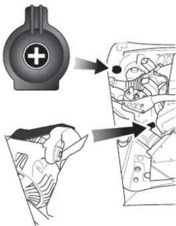
- To lessen the risk of an electrical short circuit, remove rings, metal watch bands and any other jewellery. Turn off all electrical motors and ancillaries in both vehicles. Switch off all lights except those needed to protect the vehicles or illuminate the work area. Switch off the ignition and apply the hand-brake.
3.Open the bonnet and open the cover of the jump start terminal.
-
Connect the red (+) cable between the red (+) positive terminal of the donor battery and the jump start terminal of the V12 Vanquish.
-
Connect the black (-) cable between the black (-) negative terminal of the donor battery and a good earth point in the V12 Vanquish engine bay (the alternator mounting bracket).
-
Start the donor vehicle engine and run at about 1500 - 2000 rpm.
-
Start the engine of the V12 Vanquish. Allow the engine to run until the discharged battery is sufficiently recharged to start the Vanquish without assistance.. Switch off both vehicles.
Warning: If the battery is incapable of starting the engine without assistance, the vehicle must not be driven. In this case the battery must be recharged or replaced.
Note: The recharge time will depend on the initial 'state of health' of the discharged battery.
-
Remove the black (-) negative cable from both vehicles and then remove the red (+) positive cable from both vehicles.
-
Restart the V12 Vanquish engine and take the car for a long road run if possible to fully charge the battery.
Engine Block Heating (Canadian and Swedish Cars)
Canadian specification vehicles are fitted with a 110 volt block heater. The heater connector is fitted in the front grille.
Swedish specification vehicles have a 230 volt block heater.
Consult your Aston Martin Dealer on the use of the engine block heater.
Fuse Boxes (RH drive illustrated)
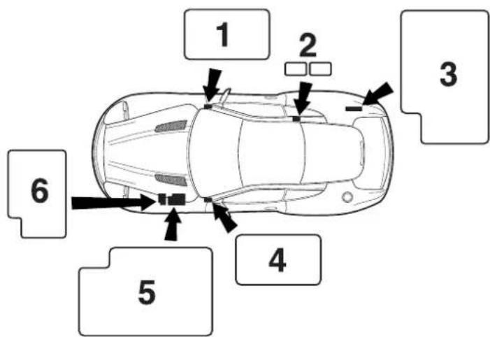
- Drivers Side Fusebox 2. Keep Alive Memory Fusebox
- Boot Fusebox 4. Passenger Side Fusebox
- Underbonnet Fusebox 6. Engine Management Fusebox
Six fuse or fuse/relay boxes are fitted to V12 Vanquish containing the fuses to protect electrical and electronic systems of the vehicle. The box locations are indicated on the diagram above. The 'Keep alive memory' fuses (2) are mounted under the rear parcel shelf/rear seat.
WARNING: Do not attempt to repair a blown fuse. This could cause a fire hazard or serious damage elsewhere in the electrical circuits.
WARNING: Do not install a fuse which exceeds the amperage for each location listed on the following fuse charts.
Underbonnet Fusebox
Fuse Rating Function
F 1 10A Transmission Controller (key power)
F 2 5A Alternator Regulator
F 3 5A Security Sounder, Ign +ve Relays 1 and 2, Console Switch Panel, Traction Status Relay
F 4 5A ABS Controller
F 5 10A Gearbox Oil Pump Relay, Starter Relay, Fan Controller
F 6 10A RH Dip Beam
F 7 10A Aircon Clutch
F 8 10A LH Dip Beam
F 9 10A Security Sounder
F 10 10(15)A Gearbox Oil Pump Relay (15 amps for GCC markets)
F 11 10A RH Horn
F 12 30A Engine Cooling Fans (Middle East Markets only)
F 13 10A LH Horn
F 14 30A Wiper Motor
F 15 10A Water Pump
F 16 30A ABS Controller
F 17 15A RH Front Fog, LH Front Fog
F 18 30A ABS Pump
F 19 10A RH Main Beam
F 20 25A Starter Solenoid
F 21 10A LH Main Beam
F 22 30A Engine Cooling Fans (Middle East Markets only)
Engine Management Fusebox
Fuse Rating Function
F 1 30A Secondary Engine Management VPWR
F 2 - Not Used
F 3 - Not Used
F 4 - Not Used
F 5 - Not Used
F 6 5A Secondary PTEC VPWR Relay
F 7 10A Secondary Ignition Coils Supply
F 8 - Not Used
F 9 - Not Used
F 10 30A Primary Engine Management VPWR
F 11 - Not Used
F 12 20A Injectors, MAF, Fan run-on relay, Ignition coils primary PTEC
F 13 - Not Used
F 14 10A Can Vent, VMVs, Misfire Module
F 15 - Not Used
F 16 15A Catalyst Monitor Sensor Heaters
F 17 - Not Used
F 18 10A Primary Ignition Coils Supply
Secondary PTEC Supply Fusebox
Fuse Rating Function
C25 20A Injectors, MAF, Secondary Ignition Coil Relay
B69 10A VMV, Misfire Detection Module
B68 15A HEGO Sensor Heaters
Drivers Side Fusebox
Fuse Rating Function
F 1 20A Drivers Seat Module
F 2 10A Door Mirror Heaters
F 3 - Not Used
F 4 - Not Used
F 5 15A Body Processor Module
F 6 5A Centre Console Switch Pack, KTM, Glass Break Sensor
F 7 15A Body Processor Module
F 8 5A Driver's Seat Switch Pack/Buckle
F 9 5A Brake Pedal
F 10 10A Airbag + Ident
F 11 10A Aircon ECU, A/C Relay
F 12 10A A/C ECU, Int Mirror, VAP, Mirror Htr Relay, Blower Relays, Rain Sensor
F 13 - Not Used
F 14 10A Instrument Pack, Gear Display Module
F 15 30A LH Heated Front Screen
F 16 5A Heated Front Screen Relay, PATS, ASM Switch Pack
F 17 30A RH Heated Front Screen
F 18 5A Instrument Pack
Passenger Side Fusebox
Fuse Rating Function
F 1 20A Passenger Seat Module
F 2 10A Door Lock Relay
F 3 5A OBDII Socket, Clock, ASM Switch Panel
F 4 5A Key Barrel Switch, Window Switches, Mirror Joystick, Ext Door Handle Switch
F 5 - Not Used
F 6 20A RH Blower Motor
F 7 20A Accessory Sockets
F 8 5A Passenger's Seat Switch Pack
F 9 - Not Used
F 10 - Not Used
F 11 20A LH Blower Motor
F 12 20A Accessory Socket Cabin
F 13 5A PATS
F 14 20A Cigar Lighter
F 15 - Not Used
F 16 5A Radio/Satellite Navigation
F 17 15A Body Processor Module
F 18 10A Dimmer Module
Keep Alive Memory Fuses (in battery compartment)
Fuse Rating Function
F 1A 25A Driver's Door Module
F 2A 25A Passenger's Door Module
F 3A 10A Radio
F 4A 10A Navigation
F 1B 20A Transmission Controller
F 2B 10A Primary PTEC
F 3B 10A Secondary PTEC
F 4B 5A Alternator
F 1C 5A Battery Conditioner Socket
F 2C 5A Tracker
F 3C - Not Used
F 4C - Not Used
Boot Fusebox
Fuse Rating Function
F 1 5A Security & Locking Module, Reverse Lamp Feed
F 2 5A Exhaust Bypass Vacuum Valve Solenoid
F 3 5A Relays 1 & 2 Coils, Battery Disconnect Switch, TPM, Telephone
F 4 20A Fuel Pump Cylinders 7-12
F 5 5A OBDII Socket
F 6 5A LH & RH Stop Lamps
F 7 20A Fuel Pump Cylinders 1-6
F 8 5A High Mounted Stop Lamp, Stop Signal to TCU, ABS, PTECs
F 9 5A Radio Telephone
F 10 10A Security and Locking Module VBAT
F 11 10A Accessory Sockets Facia and Boot
F 12 - Not Used
F 13 5A Aux Supply to Telephone
F 14 - Not Used
F 15 10A Rear Fog Lamps
F 16 30A Power Amplifier
F 17 25A Heated Rear Window
F 18 30A Power Amp Bat +
F 19 5A RH Tail Light, RH and LH No. Plate Lights
F 20 30A Gearbox Hydraulic Pump
F 21 5A LH Tail Lights, LH and RH Side Markers
F 22 - Not Used
Bulb and Fuse Replacement
A kit of replacement bulbs, fuses etc. is supplied. Any item used from the kit should be replaced at the earliest opportunity so that the full kit is always available. The kit contents are market dependant and typically include:
Specification Type Usage
12V, 21W P21W Reversing Light/Rear Fog
12V, 21/5W P21/5W Stop/Rear Light
12V, 21W PY21W Rear Indicator Light
12V, 55W H1 Headlight Main and Dip Beam
12V, 55W H27W/1 Front Fog light
12V, 27W PY27/7W Front Indicator (ROW)
12V, 28W 3457 NAK Front Indicator (USA)
12V, 5W (capless) W5W Side Lights/Side Repeater Lights
12V WY5W Side Repeater
12V, 5W (festoon) C5W Number Plate Light
Only use AML replacement bulbs.
Headlight Main and Dipped Beam Bulb Replacement
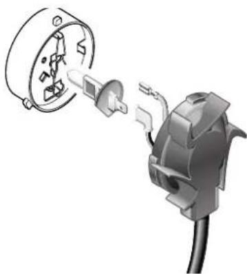
natural_image
Diagram of an electrical plug with a socket and connector, showing internal components (no text or symbols)The main and dipped beam lights are accessed through panels in the wheel arch liners.
-
Turn the steering to the opposite lock to the defective light (i.e. full right lock to access the left dipped beam light and vice versa).
-
Using a screwdriver, release the screws on the access cover in the front of the wheel arch liner and remove the cover.
-
Turn the lamp rear cover anti-clockwise and release it.
- Pull off the two electrical leads from the bulb connectors.
- Pinch the bulb retaining clip and release it.
- Remove the bulb noting its orientation.
- Hold the new bulb in a cloth or paper towel. orientate the new bulb correctly in the headlight bulb holder and secure it with the spring clip.
- Connect the two electrical leads.
- Refit and secure the lamp cover
- Refit and secure the access cover.
Front Indicator Lights / Front Fog Lights / Front Parking Lights
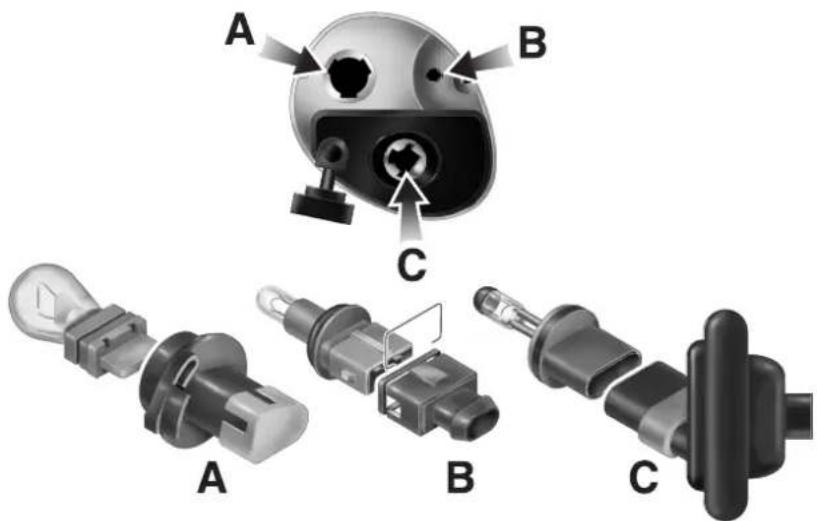
-
Using a screwdriver, remove three screws and remove the lamp assembly from the front apron.
-
If preparing to replace the front fog lamp (C), release the rubber seal from the lamp housing.
-
Turn the appropriate bulb holder (Indicator - A, Parking Lamp - B, Fog Lamp - C) a quarter turn anticlockwise and remove it.
-
Pull the defective bulb from the bulbholder and fit the replacement bulb.
-
Refit the bulbholder to the lamp assembly and, if necessary, refit the rubber seal to the fog lamp
-
Refit the lamp assembly to the car and secure with three screws.
Side Marker Lights
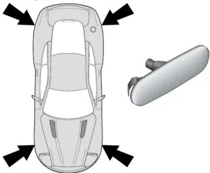
natural_image
Top-down diagram of a car showing front and side views with directional arrows (no text or symbols)-
Taking care to protect the paint work, use a screwdriver to release the light assembly from the wing and remove the assembly.
-
Remove the bulb from the light assembly and fit a replacement.
-
Refit the assembly to the wing and press in until the securing clips engage.
Rear Lights - (Indicators, Stop/Tail, Reversing and Rear Fog)
The rear lights are contained in two clusters, one either side of the car. The replacement technique for all rear light bulbs is similar.
- Remove three thumbnails and remove the cover to access the defective light cluster.
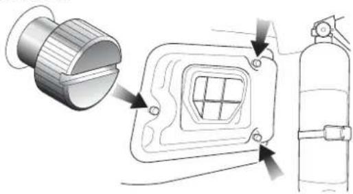
natural_image
Technical illustration of a fire extinguisher assembly with labeled components (no text or symbols present)- Rotate the appropriate light holder a quarter turn anticlockwise and remove it.
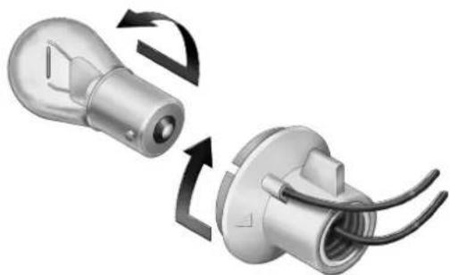
natural_image
Two 3D-rendered mechanical components with curved arrows indicating rotation or assembly (no text or symbols)-
Rotate the bulb anticlockwise in the holder and remove the bulb.
-
Fit a new bulb and turn it clockwise to lock it into the holder.
NOTE: The stop/tail light and the amber direction indicator bulbs have two filaments and offset bayonet pins. Ensure correct orientation when fitting.
- Refit the bulb holder to the light cluster and refit the rear cover.
Number Plate Lights
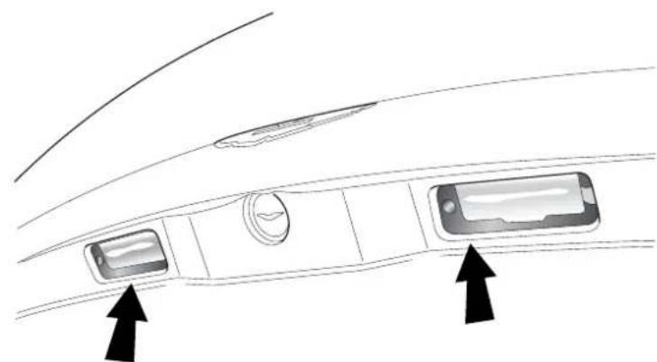
natural_image
Diagram of a car interior showing dashboard, air vent, and screen with two arrows pointing to the dashboard (no text or symbols present)- Using a screwdriver, remove two screws and the number plate light lens.
- Pull the defective bulb from its holder and replace with a new one.
- Replace the number plate light lens ensuring a good fit against the weather seal. Secure the lens with the two screws.
Rear Interior Quarter Lights
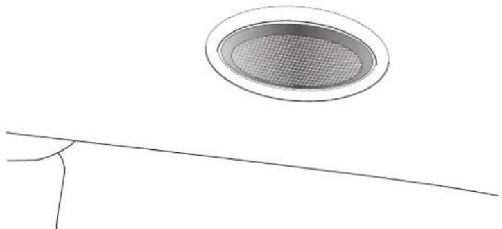
natural_image
Simple line drawing of a circular opening with a mesh grille above a thin line (no text or symbols)-
Insert a small screwdriver into the lever slot in the light lens and lever out the lens assembly.
-
Remove the defective bulb from its clips and replace with a new one.
-
Press the light lens assembly back into its housing until it clips into position.
Front Interior Lights
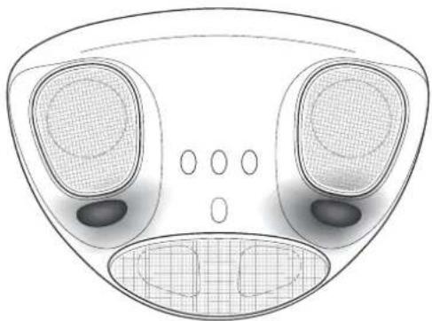
natural_image
Top-down technical diagram of a mechanical component with no visible text or symbolsReplacement of a front interior lamp bulb involves removal of the header rail trim. If a bulb replacement is necessary, please have this done at your Aston Martin Dealer.
Headlamp Ventilation
In very humid conditions some condensation may accumulate within the headlamp enclosures whilst the engine is stopped. When the engine is running and the air conditioning is switched on, the headlamp enclosures are automatically vented and any condensation will clear within a few minutes.
For rapid headlamp ventilation, use the following settings: A/C On, Maximum fan speed, Interior vents all closed. If the condensation does not clear, consult your Aston Martin Dealer.
Bodywork and Fittings
Checks and Maintenance
Door drain holes cleaned regularly as follows:
- Check the drain holes in the bottom face of each door periodically and clear if necessary with a short length of wire.
Paintwork
Caution: Automatic car washes and power-operated mops are not recommended, since prolonged use will cause fine scratches in the paint surface.
Modern water based paints are much safer and more environmentally friendly than solvent based paints. Water based paints are however more susceptible to contamination and marking by corrosive substances. The following list is not exhaustive but does indicate the most common contaminants which may adversely affect your paintwork:
- Bird Lime
- T ree Sap
- Insect Remains
- Anti-Freeze
- Oils and Greases
Other groups of contaminants may be added to this list as experience of water based paints and finishes increases.
Wash such substances from the car using clean water at the earliest opportunity, especially in sunny weather which can accelerate contamination.
Vehicle Cleaning
Paintwork - Washing
For best results, do not wash the vehicle in strong sunlight. Allow the vehicle to cool before washing. Do not use household soaps or detergents. Do not direct hoses at full force around the door and boot seals.
When washing the vehicle use plenty of clean, cold or luke warm water. Remove dust or mud from the paintwork by brushing in a gentle flow of water from a hose.
Aston Martin recommends the use of 'AUTOGLYM' car care products or preparations of similar reputable manufacture for adding to the washing water. The use of mild 'detergents' as directed by the manufacturers will also help. When dust and mud have been removed with a hose brush and water, finally dry with a chamois leather, which should be rinsed regularly in clean water.
WARNING: Washing and polishing agents containing silicone should not be applied to glass. This will reduce the efficiency of the wind-screen wipers, causing smears which will reduce visibility, particularly during darkness and in the rain.
During the winter months, it is advisable to wash the car more frequently, paying particular attention to the underside to combat the detrimental effects of any salt and sand contamination picked up from treated roads.
Paintwork - Polishing
Approximately twice a year, a good quality polish should be applied and then buffed, using a soft lint-free cloth.
Alloy wheel rims should be treated with a cleaner which is specifically manufactured for this purpose.
Upholstery, Carpets and Seats
The seats and soft trimmed components of V12 Vanquish are covered in Natural Leather Hide from Bridge of Weir.
In general, this natural leather upholstery requires little attention. The seats should be brushed with a soft brush from time to time and may be cleaned occasionally with a cloth damped in soap and water. DO NOT use detergents, quick cleansers or furniture polishes.
Several times a year, a leather conditioner or preservative should be used. Appropriate care materials are contained in the 'Bridge of Weir Leather Care Kit', obtainable from your dealer.
Note: Please take care to order the correct kit. Two care kits are available, one for cars to June 2002 and the Bridge of Weir kit for cars from July 2002 onwards.
Alcantara roof linings and other soft trimmed areas may be brushed with a soft brush. Stains from water based substances such as coffee, tea or soft drinks should be cleaned as soon as possible with mild soap and water. Please consult your Dealer for instructions on the removal of more difficult stains such as oil, grease or ballpoint ink.
Carpets should be cleaned regularly with a vacuum cleaner. Any stains or grease marks should be removed with a good quality solvent suitable for use on carpets.
WARNING: Fumes from cleaning solvents may be dangerous in confined spaces. Make sure that the car is well ventilated and follow the manufacturer's printed instructions when using these products.
Care and Maintenance of Seat Belts
To ensure that restraint webbings are in proper working order, regularly check the seat belts. Look for fraying, cuts, burns and similar problems. Ensure that the latches and buckles function correctly. If a belt is not in good condition or is not working properly, consult your Aston Martin Dealer.
Any belt that has been worn during a serious collision should be replaced by an Aston Martin Dealer.
To clean the belts, use mild soap and water; do not use bleach, solvents or dyes as they can weaken the material. Allow the belts to dry before use.
WARNING: In the interest of safety, do not allow seat belts to be retracted until completely dry.
Underbonnet Cleaning
Underbonnet cleaning using high pressure hoses or steam cleaners should not be carried out. The electronic control module connections and fuse boxes can be damaged by indecriminate use of high pressure cleaning equipment.
Storing the Car - Recommendations
Note: These recommendations apply to new and pre-owned cars either in Dealer or customer ownership.
If the vehicle is not to be used for periods in excess of three months it should be stored in a dry, well ventilated building.
Drive the car for a sufficient distance to warm the oil in the engine, transmission and final drive unit; this ensures complete lubrication of the internal components.
Check the engine coolant level. Top up if necessary with the correct antifreeze/water solution.
In order to take the weight off the tyres, raise the car with a jack and place supports under the front and rear suspension.
If the vehicle is not raised from the ground, increase the tyre pressures to 3.4 bar 340 kpa 50 psi. Cover the tyres to exclude any light. Rotate the wheels 1/4 turn every month to avoid tyre flat spots.
Press the battery disconnect switch to reduce quiescent drain to a minimum. Connect and switch on the battery conditioner to maintain the battery in a fully charged state.
Once a month, disconnect the battery conditioner, reconnect the battery by pressing the battery reconnect switch. Start and run the engine until fully warmed up. Check that there are no fluid leaks. Switch off the engine. Press the battery disconnect switch and reconnect the battery conditioner. Check and correct the tyre pressures if necessary.
When returning the car to normal service, set the tyre pressures to normal specification before driving on the road.
Extended Storage
For storage periods exceeding six months the following measures are recommended;
Run the car until there is as small a quantity of fuel in the tank as is practical for storage purposes.
Caution: Do Not Drain The Fuel System
Add Engine Oil to the remaining fuel in the tank to ensure a concentration of 2% (i.e. 20ml per 1 litre of fuel) and then run the engine for not less than ten minutes to circulate the mixture thoroughly through the entire fuel system.
Inspect the rubber connections of the cooling system and have them renewed if necessary.
Wash the bodywork of the car thoroughly and repair any paint blisters or patches of corrosion in order to prevent any further deterioration. Apply a suitable polish.
Clean the carpets and upholstery thoroughly. Dust them with an anti-moth powder and store in a dry place. Treat all leather upholstery with an appropriate leather conditioner.
If the storage building is dry leave the car windows slightly open. If there is any tendency towards dampness close the car doors and windows and place an anti-moisture compound such as Silica desiccant bags in an open metal container inside the car.
Cover the car with a cotton or fabric cover.
Recommissioning After Storage
Provided that the car has been stored in accordance with the recommended procedure, the following points only should require attention before using the car on the road.
Check tyre pressures, inflate if necessary, lower the car to the ground.
Drain the engine sump and final drive unit, fit a new engine oil filter element, then refill with the approved oils. Check the coolant level and if necessary top-up with the correct antifreeze/water solution.
Check all fluid levels and top-up as necessary. Fill the fuel tank
Caution: Starting the engine without sufficient lubrication can cause serious engine damage. Take care to establish engine oil pressure as directed in the following steps before allowing the engine to start.
Press and hold the accelerator hard to the floor (kickdown position). This will temporarily inhibit the fuel injection during cranking. Turn on the ignition. Press and hold the starter button to crank the engine until normal oil pressure is indicated on the oil pressure gauge. Release the starter button and the accelerator pedal.
Start the engine normally and check that the oil pressure and ignition warning lights go out as the engine starts indicating correct oil pressure and battery charging. Raise the bonnet and check for leaks of fuel, oil and coolant.
Carefully test drive the vehicle and check the operation of all functions.
WARNING: Braking performance can be impaired initially due to a fine film of corrosion on the brake disc surface. Drive conservatively and, when safe to do so, frequently apply the brakes until the disc surfaces have been cleaned. Full braking performance should then be restored. If in any doubt about the condition of the vehicle, have it checked by your Aston Martin Dealer.
Date of Manufacture Information (Australia only)
Date of manufacture is the calendar month and year in which the body structure and power train sub-assemblies are conjoined and the vehicle is driven from the production line.
The 'Build Date' and Vehicle Identification Number (VIN number) are stamped into the floorpan in the right side footwell.
The VIN is also stamped on the vehicle data plate mounted on the right front inner wing and on a plate in the front left corner of the windscreen.
The 10th digit of the 'Vehicle Identification Number' (VIN) gives the year of manufacture.
e.g. SCFAC23334B500001
$$ 3 = 2 0 0 3, 4 = 2 0 0 4, 5 = 2 0 0 5 \text { etc. } $$
Contents
Body 1-H-2
Engine 1-H-2
Performance 1-H-3
Power and Torque Graphs 1-H-3
Transmission - Manual 1-H-4
Final Drive 1-H-4
Steering 1-H-4
Suspension 1-H-5
Brakes 1-H-5
Towing 1-H-5
Wheels and Tyres 1-H-6
Normal Tyre Pressures: 1-H-6
Winter Wheels and Tyres 1-H-6
Exterior Features 1-H-7
Interior Features 1-H-7
Lights 1-H-8
Exterior Dimensions, Weights and Clearances 1-H-9
Interior Dimensions 1-H-10
Capacities 1-H-11
Recommended Fluids 1-H-12
Body
Two door coupe. 2 + 0 with rear parcel shelf or 2+2 seating option.
Aluminium frame with composite upper frame and crash structure. Steel shell doors and aluminium exterior body panels.
Engine
All alloy, twin overhead cam 48 valve V12. 5935 cc. Compression ratio 10.4:1.
Twin PTEC engine management systems with multi-point sequential fuel injection and 'Coil on Plug' Ignition System.
Fuel 95 RON Unleaded or 98 RON Super Unleaded.
(USA - Premium Unleaded).
2 in-tank fuel pumps.
Emission control 4 Engine Management Oxygen sensors, 4 Cata-
lyst Monitor Sensors. 2 Catalytic Converters containing 2 pre-catalyst elements and 1 main catalyst.
Evaporative loss purge system
Bore 89.0mm
Stroke 79.5mm
Spark Plugs NGK - PTR6E-13
Spark Plug Gap 1.3 ± 0.1mm
Lubrication system Wet sump pressurised lubrication
Alternator Nippondenso
Voltage Regulation 13.8V ±0.5V @ 20°C
Battery 90AH
Performance
Manual
Max Power 345kW @ 6800 rpm (460 bhp)
Max Torque 535 Nm @ 5500 rpm (400 lb/ft)
Max Speed 306 km/h (190 mph) (where permitted)
Max Engine Speed 7300 rpm
Power and Torque Graphs
Note: 92% of maximum torque is produced at only 1500 rpm
V12 Vanquish Engine
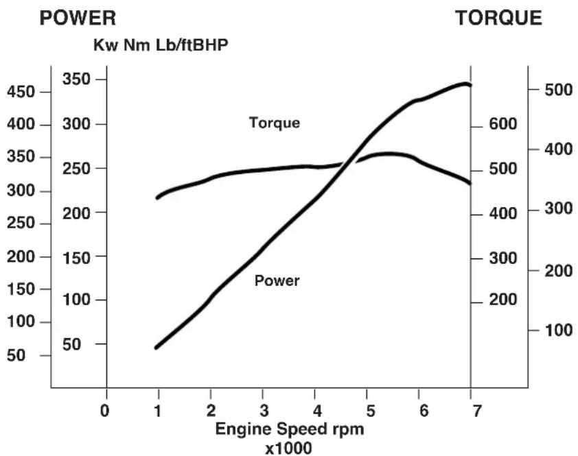
line
| Engine Speed rpm (x1000) | Power (Kw Nm Lb/ftBHP) | Torque (Kw Nm Lb/ftBHP) | | ------------------------ | ---------------------- | ----------------------- | | 1 | 50 | 300 | | 2 | 150 | 350 | | 3 | 250 | 400 | | 4 | 350 | 450 | | 5 | 450 | 500 | | 6 | 400 | 550 | | 7 | 350 | 600 |H - Specifications
Transmission
Tremec T 56 six speed transmission with paddle operated gear shift and automatic clutch.
Gear Ratios
1st 2nd 3rd 4th 5th 6th Reverse
2.66:1 1.78:1 1.30:1 1.00:1 0.79:1 0.62:1 2.9:1
Final Drive
BTR limited slip differential.
Ratio 3.69:1
Speed per 1000 rpm
6th gear 56.16 kph (34.9 mph)
Steering
Rack and pinion steering with variable power-assistance.
2.58 turns lock to lock.
Column tilt and reach adjustments.
Turning Circle 11.5 metres
Toe-In 0^ + 0.11^ - 0^ front. 0.36^ + 0^ - 0.13^ rear
(at half laden ride height - 151mm front, 172mm rear)
Suspension
Front - Independent double-wishbone, coil springs, monotube dampers and anti-roll bar.
Rear - Independent double-wishbone, coil springs, mono-tube dampers. Anti-roll bar and tie rod.
Brakes
Teves Mk 20 anti-lock braking system with traction control and Electronic Brake Force Distribution (EBD). EBD acts to redistribute brake pressure between the wheels to reduce wheel slip and delay the onset of full ABS operation.
Front - Ventilated 355mm diameter grooved steel discs with four-pot calipers.
Rear - Ventilated 330mm diameter grooved steel discs with four-pot calipers.
Handbrake - Lever and cable operated independent handbrake calipers on each rear brake disk.
Towing
The Aston Martin V12 Vanquish is not engineered to tow any form of caravan or trailer.
No towing devices are approved for fitting to the vehicle, other than the front towing eye to aid recovery or loading of the car onto a transporter.
Wheels and Tyres
Normal Use
Unique Aston Martin aluminium alloy wheels, 9Jx19 front and 10Jx19 rear.
Yokohama 255/40 ZR 19 front and
Yokohama 285/40 ZR19 rear
Tyre Ratings USA - Treadwear 180, Traction AA, Temperature A
Warning: Remove the standard road wheels with Yokohama tyres fitted and fit winter wheels and tyres to both axles before the onset of severe winter weather conditions.
Normal Tyre Pressures:
For normal use:
Front and Rear 2.62 bar 262 kPa 38psi
Winter Wheels and Tyres
WARNING: Maximum speed with winter tyres is 210 kph (130 mph)
Four special winter road wheels fitted with Dunlop SP Winter Tyres:
Tyre Pressures: Front 235/50 R18 2.62 bar 262 kPa 38 psi
Rear 245/50 R18 2.48bar 248 kPa 36 psi
Snow chains may only be fitted to the driven (rear) axle. Consult your Aston Martin Dealer.
Exterior Features
Laminated front windscreen with optional heating in some markets.
Heated rear windscreen
Heated door mirrors, optional electrochromatic and 'parkfold' features
Electrically operated door windows
Interior Features
Alcantara headlining and soft trimmed panels
Hand-crafted leather trim
Polished aluminium and painted alloy details
Electrically operated front seats
Air-conditioning
Linn 1200W in-car audio system
CD autochanger
Alarm system interacting with the central locking system
PATs immobiliser system
Electrochromatic rear view mirror
Lights Rating Type
Headlight dipped beam 55W H1
Headlight main beam 55W H1
Front fog lights 27W H27W/1
Front Indicators 27W PY27/7w (not USA)
Front Indicators 27W 3457NAK (USA)
Front Position Lamp 5W W5W
Side Repeater 5W W5W
Side marker (front and rear) 3W W3W
Tail Lamps 5W P21/5W
Stop/Tail 21W/5W P21/5W
Rear fog lights 21W P21W
Reversing lights 21W P21W
Rear indicators 21W PY21W
High Mounted Stop Lamp LED
Number plate lights 5W C5W
Note: Rear Indicator Bulbs - Use only Aston Martin PY21W (bulbs. Alternative bulbs may cause a strobing effect on the side repeater lamps.
Exterior Dimensions and Clearances
Ground Clearance - Front 162.5mm
Ground Clearance - Rear 184.3 mm
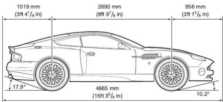
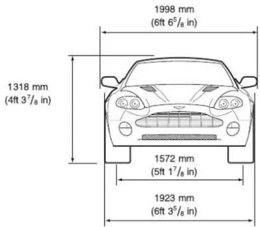
H - Specifications
Interior Dimensions
Effective Headroom - Front Coupe 937mm (36.9 in)
Effective Headroom - Rear Coupe 830mm (32.7 in)
Shoulder Room - Front Coupe 1410mm (55.5 in)
Shoulder Room - Rear Coupe 1250mm (49.2 in)
Hip Room - Front Coupe 1331mm (52.4 in)
Hip Room - Rear Coupe 1079mm (42.5 in)
Effective Legroom - Front Coupe 984mm (42.8 in)
Interior Volume Coupe 2.216 m3 (78.3 ft3)
Boot (Trunk) Volume Coupe 0.22 m3 (7.78 ft3)
Weights
Kerb weight 1835 kgs (3969 lbs)
Gross vehicle weight 2175 kgs (4630 lbs)
Capacities
Europe UK USA
Engine sump (incl. filter) 9.5 litres (16.7 pints) (10.0 Qts)
Engine sump (excl. filter) 8.5 litres (15.0 pints) (9.0 Qts)
Engine cooling system 15 litres (26.4 pints) (16.5 Qts)
Screen washer reservoir 2.0 litres (3.5 pints) (2.2 Qts)
Brake fluid reservoir 0.5 litres (1 pints) (0.5 quarts)
Power Steering reservoir 1.0 litres (1.7 pints) (1.0 quarts)
Gearbox & Cooler 4.17 litres (7.3 pints) (4.6 Qts)
Final drive 2.0 litres (3.52 pints) (2.2 Qts)
Fuel tank 80 litres (17.6 galls) (22.0 galls)
Fuel reserve 16 litres (3.5 galls) (4.5 galls)
Note: Only about 11 litres (2.5 Imp Gallons/3.0 US gallons) of the reserve may be used. This gives sufficient fuel for approximately 80 kilometres (50 miles) of normal motoring.
H - Specifications
Recommended Fluids
Engine oil Mobil 1 0w-30
Engine coolant 60% water, 40% Havoline OAT
Caution: Do not mix OAT anti-freeze with glycol based antifreeze.
Gearbox oil Texaco Dexron III
ASM Fluid FL CS Speed (Pt No. 699751)
Final drive oil Mobil 1 SHC 80W-140-ID
Brake/Clutch fluid Castrol Dot 4 Brake Fluid
Power steering fluid Texaco Cold Climate Power Steering Fluid
A/C refrigerant R134A (HFC134A)
Engine Oil
Caution: To achieve the desired high performance of synthetic lubricants, do not mix with mineral oils.
Contents
Audio System
Audio System 2-A-1
Navigation System 2-A-2
System Description 2-A-2
System Operation 2-A-2
General Information 2-A-3
Security Code Number 2-A-4
Sound System Controls 2-A-5
Radio Operation 2-A-6
FM and AM Reception 2-A-7
Audio Control in Navigation Guidance Mode 2-A-11
Radio Operation 2-A-14
Radio Data System (RDS) and Traffic Announcements (TA) 2-A-16
RDS and TA operation 2-A-18
Traffic Announcements (TA) (United Kingdom and Europe only) 2-A-19
RDS and TA Operation (continued) 2-A-20
RDS Trouble-Shooting Guide 2-A-22
Radio Set-up Modes 2-A-23
Set-Up Parameters 2-A-24
Cassette Tape Player Operation 2-A-25
Compact Disc (CD) Player 2-A-29
CD Changer – Loading and Unloading Discs and Magazine 2-A-30
CD Operation 2-A-31
CD Player Fault Diagnosis 2-A-34
Care of the Audio System 2-A-36
Cassettes 2-A-36
Compact Discs (CDs) 2-A-36
Audio Guide
Navigation System
System Description
Introduction 2-B-1
Using the Controls 2-B-11
Selection Screen Example 2-B-16
Voice Guidance 2-B-19
Screen Guidance 2-B-19
Typical Example 2-B-20
Route Guidance 2-B-26
Menu Summary 2-B-27
System Operation
Initialisation 2-B-28
Navigation Menu 2-B-29
Destination Menu 2-B-30
Setup Menu 2-B-36
Options Menu 2-B-39
Route Calculation and Guidance 2-B-43
Driving Off 2-B-45
Screen Guidance 2-B-47
Full Screen Mode 2-B-47
Split Screen Mode 2-B-47
Route Menu 2-B-48
Route 2-B-48
Delete Current Destination 2-B-49
Edit Way Points 2-B-51
Additional Guidance Features 2-B-52
Long-Haul Areas 2-B-54
Long-Haul Cities 2-B-57
General Information
The bespoke audio system comprises a radio, cassette tape player and compact disc (CD) player. The system is powered by a boot mounted Linn 13 channel power amplifier rated at 1200 Watts. Sound output is via Linn compound speakers, each consisting of a midrange unit, a tweeter and a super tweeter. One of these units is mounted in each door and two are mounted in the rear parcel shelf together with a centrally mounted base drive unit.
Warning: This audio equipment is capable of delivering extremely high levels of performance. As a consequence, if abused, permanent hearing loss could result by listening at excessively high volumes for a prolonged periods of time. Common sense should be followed in this regard.
Caution: Use of the audio system at very high volume levels for a prolonged period may damage the speaker system.
The system has an FM aerial mounted in the rear quarter windows.
The system is operated by controls on the audio panel. The audio panel also has an alpha-numeric display which provides information, including text messages, relating to operation of the unit.
The display is also used by the navigation system (where fitted) to display navigation information. For details refer to the 'Navigation System Operating Instructions'.
The in-car phone system can also be controlled from the audio control panel allowing 'handsfree' phone operation for increased safety when driving. For details refer to the 'Telephone Quick Guide' in this Owner's Guide and to the Motorola M8989 Users Guide supplied separately.
Security Code Number
The unit is protected by an anti-theft security code. If power to the radio drops to 5 volts or less, (discharged battery), or there is a power interruption/disconnection, the radio display will indicate CODE. At this point the radio will not operate until you have re-entered the correct security code.
The four-digit code for your radio is listed on the two radio security cards supplied with the vehicle. Enter the code by using the pre-set buttons 1 to 9; a 'beep' sounds when the code is entered correctly. If the code is not entered correctly, then begin the code entry again. If, after three successive attempts, the code is not properly entered, the display indicates WAIT.
In this condition the radio will not accept any further entries until it has been left on for one hour. After one hour in the ON position the radio will accept three further entries.
Should you lose your radio security cards, contact your Aston Martin Dealer, who, for security reasons, will require proof of vehicle ownership before issuing replacement security cards.
Sound System Controls
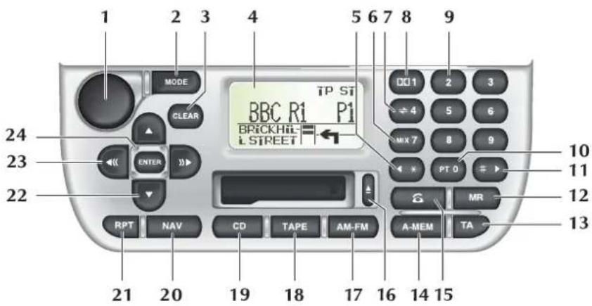
- ON/OFF and volume control.
- MODE scroll through modes to select sound quality settings.
- CLEAR last digit (phone) last entry (navigation).
- Sound system display and navigation screen (where fitted).
- Seek stored phone number in the phone memory.
- MIX CD, preset 7 and phone key pad 7.
- Programme change button (cassette), preset 4 and phone key pad 4.
- Dolby B noise reduction (cassette mode) preset 1 and phone key pad 1.
- Preset buttons phone key pad.
- Programme Type (all markets). Traffic Information (USA and Canada only).
- Seek stored phone number in the phone memory.
- MR Memory recall – Phone memory access.
- TA Traffic announcement and Radio Data System (TA) (UK and Europe).
- A-MEM - Automatically set station presets.
- Phone - Enter phone mode, send and end a call.
- Cassette tape eject button.
- AM-FM band select.
- TAPE Cassette tape select.
- CD select.
- NAV Navigation select.
- RPT - Repeat last track, repeat CD, Repeat last navigation message.
- Manual tune to AM/FM stations. CD select in CD mode.
- Seek AM/FM station, fast forward and rewind in TAPE mode.
- ENTER command in Navigation mode.
Radio Operation
Radio Display Panel
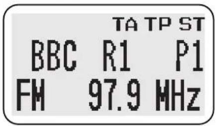
The first line shows the functions which are currently active.
TATraffic announcement selected.
TPTraffic Programme (Europe, United Kingdom and USA).
STStereo.
P1 Preset button allocated to the displayed station.
FM and AM Reception
FM reception has the advantages of low noise, minimal distortion, wide dynamic range, extended frequency response, and is usually broadcast in stereo. However, as FM frequency waves are relatively short and travel in a straight line, they can sometimes be impeded by obstructions, adversely affecting reception in some parts of the country.
Whilst FM reception will generally provide better quality sound, AM reception or Medium Waveband (MW) and Long Waveband (LW) (United Kingdom and Europe) may be better in remote areas not covered by the shorter range FM transmitters.
When experiencing poor FM reception, background noise can be reduced by adjusting the Mode button into Treble adjustment position and reducing the treble setting.
ON/OFF and Volume Control
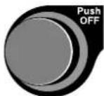
Push the control to switch the radio on. Push again to switch off. Turn the control clockwise to increase volume.
Automatic Volume Control (AVC)

This is a feature which raises the volume of the radio to overcome road noise as the vehicle speed increases. To switch AVC on or off, press the volume knob for more than two seconds. The current state will be displayed i.e. AVC ON/AVC OFF.
To toggle ON/OFF momentarily, press the volume control knob again to change the state. The AVC level can be adjusted from 1 to 5 by turning the volume knob while in AVC ON mode. When AVC is ON, it is possible to override the automatic mode by adjusting the volume manually.

Mode Button
Press MODE repeatedly to cycle through the various modes. Once a function has been selected, turn the volume control to adjust sound quality. After about five seconds the radio will return to normal volume control mode.
The modes are:
NAVSet the relative levels of voice guidance volume to audio volume (voice guidance emphasis) – Only vehicles with Navigation Systems.
BASSIncrease/decrease.
TREBLE Increase/decrease.
The bass and treble positions for radio, cassette tape and CD are automatically memorised, allowing individual settings for each mode.
BALANCELeft to right.
FADEFront to rear.
SUB-WOOFERSet sub-woofer level from -7 to +7.
POSITIONUsing volume control, set speaker delays to optimise stereo sound for a selected seating position.
For example sound can be optimised for the driver on the right by introducing a delay in speaker (A), effectively moving speaker (B) to the position shown, balancing the stereo effect.
Scrolling past POSITION returns the screen to normal display.
Optimising Sound
Sound can be optimised for the following seating positions:
- F ront Left
- F ront Right
- Centre (All)
To Change the Position Setting:
Press the mode switch until POSITION is displayed then turn the volume control to cycle through the available positions.
Preset Buttons
Warning: Do not attempt to set the station preset while driving. Do this before starting a journey.

In each waveband, nine stations can be memorised in the bank of preset buttons marked 1 to 9. After tuning to a station, hold the chosen preset button for at least two seconds. The unit will 'beep' to indicate that the station has been stored. This station can be recalled from this preset memory by pressing the button momentarily, for less than two seconds.
Seek and Manual Tuning
Momentarily pressing the left or right buttons will activate the radio in the seek mode, making the tuner search up or down the frequency range for the next available station.
Push and hold the up and down buttons to tune the radio manually, the display counts up or down to the frequency required. Incremental adjustment can be made by momentarily pressing the buttons until the required frequency is reached.
The ENTER button is used to enter commands in Navigation mode.
Audio Control in Navigation Guidance Mode
When the navigation system is active, the display is used to show navigation information. Under navigation guidance the screen can be in one of two modes:
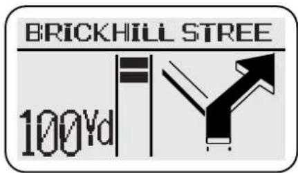
Full Screen
Navigation information only,
or
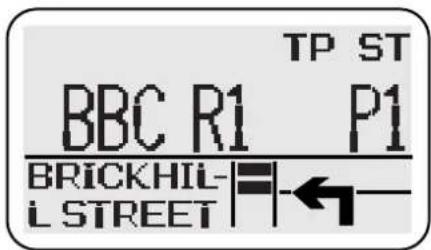
Split Screen
Upper screen (Audio).
Lower screen (Navigation).
Navigation system active, means that a destination has been set and guidance is activated.
When in full (navigation) screen mode you can adjust the volume of the audio source currently selected.
To gain full audio system control, press the required audio source button i.e. AM-FM, CD, TAPE or PHONE. This will force the display into split screen mode (if previously in full) and allow audio system adjustments to be made.
Approaching a Manoeuvre Point
When under navigation guidance, the display will change to full screen (if previously in split) when the vehicle is within 0.3 miles (0.5 km) of a manoeuvre point (1.5 miles (2.4 km) on motorways), i.e. the point where a navigation instruction is necessary.
Guide Method
Full and split screen behaviour can be set-up in the Guide Method menu as follows:
Hybrid ON – The display is normally in split screen mode. At 0.3 miles (1.5 miles on motorways) distance from a manoeuvre point, the display changes to full screen to alert the driver to an approaching manoeuvre. In this zone, full navigation screen is maintained until the manoeuvre point has been passed, whereupon it will revert to split.
Pressing an audio source button in this zone will change the display briefly to split screen, allowing audio system adjustments to be made.
In split screen, pressing NAV will force a full screen which will be maintained until the next manoeuvre point is approached.
Hybrid OFF - The display is normally in full screen.
Pressing a source button will change the display briefly to split, while audio adjustments are made, and then revert to full.
See the Navigation Operating Instructions for setting the guide method.
Audio Control in Navigation Guidance Mode (continued)
In-car telephone (If fitted)
Use of the in-car telephone is not restricted in any way by the navigation system and retains full functionality. If an incoming call is received while under navigation guidance, the display will switch to split screen, if previously in full screen mode. For full details refer to the In-car Telephone Operating Instructions.
Navigation voice guidance
The emphasis of voice instruction over the audio volume is set using the Mode button. Voice guidance emphasis also applies to any traffic announcements that may be broadcast.
Radio Operation

Band Switch AM-FM
Band selection will be shown in the display panel. Pressing AM–FM repeatedly will cycle the radio through FM, Medium and Long Wavebands (where applicable). When a cassette tape or CD is being played, pressing the Band Switch selects radio operation.

Auto Memory (A-MEM)
The automatic memory function programmes the nine strongest stations on the selected waveband into Presets 1 to 9.
To activate this function, hold the A-MEM button for at least two seconds.
The radio is muted briefly while it searches the waveband for the nine strongest stations. A beep indicates that programming is complete and Preset number 1 is selected.
If stations cannot be found for all preset buttons, those which are found will be allocated to preset buttons, starting with number 1, leaving the remainder not programmed. The display will show NO FM or NO AM if unprogrammed buttons are selected.
To switch between the A-MEM preset stations and your own presets, press the button for less than two seconds.
A-MEM with Radio Data System (RDS) Selected
(United Kingdom, Europe, USA and Canada)
If the A-MEM function is operated while in RDS mode, the radio will be muted briefly, while a search is made for the nine strongest RDS stations. Similarly, if A-MEM is used with Traffic Announcement (TA) activated, the radio will only programme the nine strongest RDS stations carrying traffic information.
If stations cannot be found for all preset buttons, those which are found will be allocated to preset buttons, starting with number 1, leaving the remainder not programmed. The display will show NO FM or NO AM if unprogrammed buttons are selected.
When used correctly, RDS and TP are very effective additional radio capabilities. However, if these facilities are used without full understanding, they may cause confusion to the operator. This is less likely to occur as more RDS stations become available.
Radio Data System (RDS) and Traffic Announcements (TA)
(United Kingdom, Europe, USA and Canada)
The audio system is equipped with Radio Data Systems (RDS) which assists in finding and staying tuned to a chosen radio station. The RDS radio signals also provide additional information as follows (dependent upon the service provided by the transmitter).
RDS Station Name Display
When RDS is selected the station name is displayed in eight characters as well as the frequency. The display also identifies network 'splits', where different programmes are being broadcast on FM, Medium Wave or Long Wave.
Automatic Re-Tuning to Follow Network Stations
RDS provides fully automatic radio tuning for network stations. It tunes to a signal not a frequency. The RDS will search out the strongest signal available for a given station and automatically switches frequency as necessary.
RDS Station/Programme Type Display and Search
RDS provides information as to the type of material broadcast by the station or programme that is on i.e. News, Classical, Rock etc. Apart from being able to display this, the radio can search for one specific programme type that is selected.
RDS Priority Programme Type Auto Re-Tuning (United Kingdom and Europe only)
Similar to Traffic Announcement this can be selected to interrupt and switch to the selected programme type, for its duration, i.e. NEWS.
Local Radio Station Traffic Information
(United Kingdom and Europe only)
RDS provides travel information relevant to the vehicle location. When the authorities learn of a traffic problem, they inform the nearest local radio station. The traffic announcement (TA) is then broadcast by the transmitters in the relevant area.
The TA will interrupt radio, cassette tape or CD play, on all equipment with the RDS feature, provided Traffic Announcement has been selected. If the volume control is set at minimum it will automatically increase to an audible level for the duration of the traffic new flash.
When the news flash is over, the system switches back to the original listening choice and volume setting.
RDS and TA operation

To activate RDS: press the TA button and hold for at least two seconds. (Display: RDS ON)
To de-activate RDS: press the TA button again and hold. (Display: RDS OFF)
When RDS is activated, the radio gathers RDS information and displays the Service name and frequency, provided the programme chosen is an RDS station.
If not, the radio will remain on station, the display will show the frequency and RDS will remain on in readiness for a signal.
When listening to a National Network Station, or a station that broadcasts on more than one frequency, the radio will re-tune to the strongest available signal. This 'network following' will continue throughout the journey. (The unselected presets will also receive new frequency information, if appropriate.)
When RDS data is lost and no alternative frequency signal is available, the radio will stay on station, the display shows the frequency only and RDS remains on in readiness for the signal to recover.
If the RDS function does not respond correctly, refer to the RDS Trouble-Shooting Guide.
Traffic Announcements (TA) (United Kingdom and Europe only)
To activate TA: Press the TA button and hold for at least two seconds to activate RDS.
Then press TA momentarily (less than two seconds). A beep indicates TA activation.
To de-activate TA: Press the TA button momentarily. A beep indicates de-activation.
TA will be shown at the top of the display. The radio then checks that the station has RDS TP (Traffic Programme); indicated by TP at the top of the display. If TP is not available on the current station, the display will show TP SEEK while it searches for a station that does have it.
With TA activated, transmitted announcements will interrupt radio, tape or CD play. If set at a minimum, the volume will be increased for the announcement, returning to normal setting afterwards.
When received, the display shows: TRAFFIC INFO.
TA – preset minimum volume (United Kingdom and Europe only).
When the radio is set to minimum volume and a traffic announcement occurs, the volume is raised to a preset level. This level is adjustable by pressing and holding the MODE button for more than two seconds. The volume level is adjusted between 1 (min.) to 6 (max.) by turning the volume control knob.
RDS and TA Operation (continued)

PT – Programme Type
This has two functions:
To display current station programme type and to select a programme type and re-tune to it.
Momentarily press the PT button to display the current station programme type. Use the tuning buttons to cycle through the available programme types, press the PT button again to activate a search for the selected programme type. If there is a station with the correct PT then the radio will return to it. If not, the radio will indicate NO PTY and return to the current station.
Priority Programme Type (United Kingdom and Europe only)
Works in two ways, as an interrupt or as a 'PTY Following'.
Press and hold the PT button to display the default priority programme type NEWS. Use the tuning up and down buttons to cycle through the available programme types.
Press and hold the PT button again to activate the selected priority programme type, PTY. The radio will now wait for RDS information to indicate that a station has changed its programme type, i.e. to NEWS. The radio will now re-tune to the new station for the duration that it remains on that programme type.
If the current station is already on the selected priority programme type, then when this station is lost, the radio will attempt to find another with the correct programme type.
To cancel priority programme type, press and hold the PT button, the PTY indicator on the display will be cleared.
TA and PTY Interrupt Skip (United Kingdom and Europe only)
Interruptions for Traffic Announcements, NEWS or other selected priority PTY, can be skipped by pressing TA during the interrupt. The radio returns to the previously selected station.
Notes:
Interrupt skip will not cancel the activation of this feature, and it will remain ready for the next interrupt.
PTY and Priority PTY features are reliant upon the broadcast information from radio stations, and may be much better in some areas than others.
Change Audio System Source

Press any of the audio system source buttons or phone mode button (where fitted) to change the source selected.
RDS Trouble-Shooting Guide
| Incorrect response from RDS Reason and rectification | |
| Radio does not display programme name. | Check that RDS is turned on by pressing the TA button for more than two seconds. The display will confirm RDS ON or RDS OFF. If radio does not display programme service name, try re-tuning to another station with RDS. |
| Station name is lost and displays frequency only. | Radio reception lost due to vehicle moving out of transmitter range, or loss of signal due to an obstruction. If the latter is the case, wait until the vehicle is clear of the obstruction. There is a short delay before the station name returns. |
| Upon operating the A-MEM, most or all of the presets display NO FM when pressed. | The radio cannot find nine FM, RDS FM or TP stations dependent upon the mode selected. If this occurs, switch off RDS or TA and reselect A-MEM. |
| Upon pressing the TA button the radio re-tunes to another station and displays TP SEEK. | The station selected does not have TP/TA facility, the radio will re-tune to one that does. |
| Radio sound goes off and the display shows PI SEEK. | The RDS radio station selected is unable to confirm that the frequency tuned to has the correct RDS data – programme identification (PI). It will then seek a frequency that has the correct data. |
| Radio ‘beeps’ and the display shows NO TP/TA and turns off TA. | The RDS TP radio station selected is unable to receive Traffic Programmes, due to the vehicle moving out of transmitter range, or due to an obstruction. If required, re-tune to another station or continue to listen to the station with RDS TA OFF. |
Radio Set-up Modes
This function allows the radio to be set up to suit the user's operating preferences. By moving into SET UP mode and using the preset buttons, the owner or Aston Martin Dealer can choose whether certain radio facilities are active or switched off.
When in SET UP, pressing the relevant preset button, as detailed below, will show on the display the facility that has been selected and its state. The selected facility can be changed to the user's preference by pressing the preset button again.
To enter the set up mode: Press Tape Eject and AM/FM buttons simultaneously.
The display will show SET UP. The following preferences can then be selected and changed, in any order, as long as no more than 15 seconds elapse between Presets. After 15 seconds the display will clear.
Set-Up Parameters
Preset 1 Press Preset 1 to select the market mode, thereby enabling or disabling RDS, depending upon RDS availability in the user's country.
Preset 2 This Preset controls the Tape Clean reminder facility. To switch off this reminder, press the Preset 2 button until TAPE CLN OFF shows on the display.
Preset 3 Not Applicable.
Preset 4 This Preset controls the telephone Mute facility. If a telephone is installed, turn the telephone Mute on by pressing the Preset 4 button until TEL ON shows on the display.
Preset 5KEY OFF EJECT – Sets the cassette tape to automatically eject when the ignition is turned off.
Preset 6FM Vol. - High or Low
Preset 7Blank
Preset 8AF ON/OFF – Used when specific RDS problems occur, that may be helped.
Preset 9Blank.
Preset 0 This Preset is used to select one of the following regions: Europe, USA, Australia or Japan. Regional settings determine the correct frequency increments required for seeking stations, automatic tuning etc.
Cassette Tape Player Operation
If no cassette is present, pressing the TAPE button will have no effect.
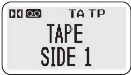
If a tape is present, the display will indicate which function has been selected. Messages include:
SEEK UPSearch to beginning of next track.
SEEK DOWNSearch to beginning of track being played.
REWINDRewind.
FAST FORWARD Fast forward.
TAPE LOADING Loading a tape into the mechanism.
TAPE EJECTEjecting a tape.
TAPE CLEAN Tape mechanism requires cleaning.
Tapes will play immediately upon loading. After playing one side, it will auto-reverse and play the other. If a Metal or Chrome, (non ferric) tape is used, the equalisation will be automatically adjusted.

Eject
When a cassette is inserted into the player, the aperture door closes. Press the Eject button to remove the tape.
Tape-In Indicator
When a tape is present, an indicator is shown on the display.

Tape Button
If you are playing radio or CD, pressing TAPE will play any cassette that is in the player.

Dolby B
If you are using a cassette with a 'Dolby' recording, to select the noise reduction system, press the Dolby on/off button. An indicator is shown on the display.

Programme Change Button
While playing a cassette, press this button to change to the other side of the tape.

Forward/Rewind control
This control has two functions, seek to track and fast wind in each direction. Momentarily pressing the right hand button will activate tape search to the beginning of the next track. Similarly pressing the left hand button will activate tape search to the beginning of the current track being played.
Pushing and holding either button for two seconds will activate continuous fast forward or rewind of the cassette. This can be cancelled by pressing the control in either direction.

Repeat
Press RPT to seek to the beginning of the last track played.

Priority Programme Type (United Kingdom and Europe only)
Works in two ways: as an interrupt, or as a 'PTY Following'.
Press and hold the PT button to display the default priority programme type, NEWS. Use the tuning up and down button to cycle through the available programme types.
Press and hold the PT button again to activate the selected priority programme type, PTY will be shown in the display to indicate that it is active. The radio will now wait for RDS information to indicate that a station has changed its programme type, i.e. to NEWS. The radio will interrupt the cassette tape for the duration that it remains on that programme type.
If the current station is already on the selected priority programme type, then when this station is lost, the radio will attempt to find another with the correct programme type.
To cancel priority programme type, press and hold the PT button, the PTY indicator on the display will be cleared.

Traffic Announcements (TA) – Local Radio Stations
(United Kingdom and Europe only)
To select traffic announcement: Press TA, a 'beep' will sound and TA will be shown in the display. When there is a traffic announcement, the radio will interrupt the cassette tape and the display will show TRAFFIC INFO.


Change Audio System Source
Press any of the audio system source buttons or phone mode button (where fitted) to change the source selected.
Compact Disc (CD) Player
The radio control panel is used to control the CD autochanger. The CD unit comprises an autochanger which contains a magazine to take six discs, each mounted in a tray. This equipment is installed in the luggage compartment.
CD Check Sequence
When the CD Player is switched on it performs a check sequence. Each disc tray in the magazine is checked in turn and the display will show CHECK and the tray number. When the six trays have been checked the player will return to disc one.
CD Changer – Loading and Unloading Discs and the Magazine
Ejecting the Magazine:
Slide the magazine door to the right (A). Press the eject button (B), the magazine will then partly eject from the changer.
Pull out the disc tray from the magazine (C) and load your six selected discs into each tray with the labels facing upwards (D), taking care not to touch the playing surface. Push the tray back into the magazine until it clicks.
Disc tray slots are numbered 1 (bottom slot) to 6 (top slot).
Inserting the Magazine:
Insert the loaded magazine into the changer (E) with the arrow mark facing upwards and pointing towards the CD changer. Ensure that it clicks into position. Close the sliding door. Keep the sliding door closed to prevent dust entering the playing mechanism.
CD Changer – Loading and Unloading Discs and Magazine
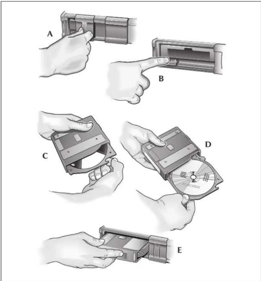
CD Operation
The radio display shows which CD function has been selected.
Example of CD Display, playing track 16 of CD3.
DISC 03 TRACK 16
Other messages:
NO DISC – in the selected position.
NO MAGAZINE – in the CD Changer.
CD1 MIX 10 – the player is playing CD1 in MIX mode (track 10).
CD DMIX – all CDs are in MIX mode.
MAG EJECT – the magazine is being ejected.
DISC CHECK – the Autochanger is checking there is a disc.
PAUSE – the Autochanger is paused and ready to play.

CD Button
Press CD when in either tape or radio mode to select CD mode.
CD Selection
Buttons 1 to 6 directly select the CD in those positions in the autochanger magazine. If there is no disc in the selected position, NO DISC will be displayed. If there is no magazine in the changer, NO MAGAZINE will be displayed.

In CD mode you can also press the up and down buttons to scroll through the CDs.

MIX and Disc MIX
Momentarily press MIX to play the tracks of the selected disc in random order. To cancel, press MIX again or any other button.
Press and hold to select CD MIX. The player plays tracks from any disc in random order. To cancel press MIX again or any other button.

Forward, Reverse Control
This control has two functions: seek to track and fast play in each direction. Momentarily press the right-hand button to skip to the next track. Repeated pressing will select further tracks.
The left-hand button returns to the beginning of the current track. Repeated pressing selects previous tracks.
Pushing and holding either button selects continuous fast forward or fast reverse playing of the CD.
The sound level reduces during cueing and reviewing modes.

Repeat
Press RPT to seek to the beginning of the last track played.
CD Player Fault Diagnosis
If the CD Player does not operate properly, an error message will be displayed. The following table gives fault diagnosis for each error message displayed.
| MESSAGE CAUSE | SOLUTION | |
| E-01 | Disc-change malfunction. | See your Aston Martin Dealer. |
| E-02 | Disc is in player mechanism. | Press the magazine eject button, insert an empty magazine into the player. Eject the magazine from the player by pressing the eject button. If the magazine fails to eject from the player, see your Aston Martin Dealer. |
| E-03 | Disc-change malfunction. | If the error message goes out within a few seconds, the unit is working correctly. If the error message stays on, see your Aston Martin Dealer. |
| E-04 | ||
| E-05 | ||
| E-06 | Disc-changemalfunction. | Press the magazine ejectbutton and pull out themagazine. Check thatthe error message goesout, then operate thefunction again. If themagazine cannot bepulled out, see yourAston Martin Dealer. |
| E-07 | Magazine ejectionimpossible. | Press the magazine ejectbutton. If the magazinedoes not eject, see yourAston Martin Dealer. |
| E-30 | High temperature. The errormessage willgo out when thetemperature returns towithin the operatingrange. | |
| NOT CONNECT | Bad connection ordisconnected CDchanger. | Check connectionbetween CD changerand control unit. Seeyour Aston MartinDealer. |
| NO MAGAZINE | No CD magazine in thechanger. | Insert the CD magazine. |
| NO DISC | No CD in tray ofmagazine. | Insert a CD into the trayof the magazine. |
Care of the Audio System
Do not use petrol, solvents or abrasive cleaners on the radio. Wipe the surface of the radio with a lint-free cloth to remove dust. Slightly moisten the cloth with clean water to remove any finger marks from the outside surface of the radio.
Cassettes
Always use good quality cassettes up to C90 in size. Low cost tapes can cause jamming, the sound quality will be inferior, and they can create a fast build-up of deposits on the play-back head.
Before playing, check the cassettes to ensure that the tape is not loose on the spools. If necessary, take up the slack by gently turning the spools with the end of a pencil. A jammed or sticking tape will cause the auto-reverse mechanism to operate continuously.
Cassettes should be stored in their library cases away from direct sunlight. Do not store cassettes in door pockets, they could be affected by the magnets in loud-speakers which might impair the sound quality.
After approximately 15 hours playing time, the display on the radio will show CLEAN TAPE. Clean the tape mechanism itself using a mechanical type cleaner with a wetting agent in an approved kit available from your audio dealer. Do not use abrasive type cleaners as they can cause excessive wear on the play-back head.
Compact Discs (CDs)
When handling CDs, do not touch the playing surface. When they are not being used they should always be stored in their cases away from direct sunlight, heat and dust. Scratches, finger-marks or dust on the surface of a disc can cause the optical pick-up to skip tracks. If the surface is dirty, use an appropriate CD cleaner.
Do not attempt to play damaged, warped, cracked or oversized discs. They could seriously damage the play-back mechanism.
Introduction
The navigation system assists the driver by providing a route to a selected destination. Guidance is given by means of audible instructions (voice guidance), complemented by diagrammatic turn information which is displayed on an LCD display on the front panel of the radio. Digital map information is held on a digital versatile disc (DVD), which is loaded into the navigation control unit housed in the luggage compartment.
The system has an extremely comprehensive range of features, yet is easy to use. Some time spent reading this handbook will ensure that the best results are obtained.
The LCD display provides full information for operating the system by means of menus, text screens and turn displays. Screen selections are made by the controls on the front panel.
How the System Works
The system uses signals from the Global Positioning System (GPS) satellites, which allow the approximate vehicle position to be calculated. This is combined with information from vehicle sensors and data from the map DVD to establish the true vehicle position.
-
The map CD reflects road configurations as existing when the disc was written. It comprises data and information from government and other sources. Accordingly, the disc may contain inaccurate or incomplete information due to the passage of time, changing circumstances, and due to the nature of the sources used. The disc does not include or reflect information on neighbourhood safety; law enforcement; emergency assistance; construction work; road or lane closures; vehicle or speed restrictions; road slope or grade; bridge height, weight or other limits; road or traffic conditions; special events; traffic congestion; or travel time.
-
Only operate, adjust or view the system when it is safe to do so.
Safety Information
IMPORTANT
Read handbook and obey traffic regulations.
ENTER
When the system is switched on, the road safety caution screen is displayed.
To continue and use the system, push ENTER.
For best results, always use the latest version of the map DVD (navigable map database). Map information is regularly updated, but all areas are not necessarily covered to the same level of detail. Some areas, in particular private roads, may not be included on the database (non-digitised roads).
While driving under route guidance, only follow an instruction when it is safe to do so, as the system cannot be aware of changing conditions, for example turn restrictions, roadworks or diversions. Use voice guidance as much as possible, and only view the display when driving conditions permit.
If the system is to be used for an extended period of time with the vehicle stationary, place the vehicle in an open, well ventilated area to disperse exhaust fumes. Ensure that the engine is running, to avoid draining the battery.
About this Guide
This guide shows examples of the on-screen menus, explains how to operate the controls, and gives an example showing how to set a destination. After becoming familiar with the controls, follow the on-screen menus and prompts, to operate the system as required.
To find a particular menu, use the Menu Structure shown in the quick reference guide. This information is repeated on page 6
Throughout the handbook, the expression 'Select an item' (or similar wording), means 'Highlight the item using the Cursor control', and push ENTER.
Reception of GPS Signals
GPS signals are highly directional and reception may occasionally be interrupted. Some examples of situations likely to cause problems are shown below.
- Inside tunnels.
- Inside buildings.
- Roads under raised highways.
• Densely tree-lined roads.
• Forest roads between mountains. - Between tall buildings.
- Roads under cliffs.
• Metal objects placed on or near the system aerial.
Errors in Vehicle Position
Under certain driving conditions, it is possible that the vehicle position shown may be incorrect. Some examples are shown below.
- When the vehicle is transported by ferry or train.
• After vehicle battery removal or supply fuse failure.
• After the vehicle has been rotated on a turntable.
• W here there are two roads parallel to each other. - Elevated roads in proximity to other roads.
The position will usually be corrected automatically. If the problem persists, consult your Aston Martin dealer.
Route Guidance Precision
Under certain driving conditions, it is possible that the route guidance may be inaccurate. Some examples are shown below.
- Deviation from a route may cause incorrect guidance until the route has been recalculated.
- Route guidance may be given where no turn is required.
- If there is no road, or only a narrow track, to the final destination, guidance will be given to the nearest point possible.
- No guidance is given while reversing.
- If driving at high speed or on very dense road networks, it may not be possible to recalculate the route in time for the next instruction.
- On familiar roads, personal route preferences may not always be followed.
Map DVDs
To use the system in other countries or geographical areas, obtain the appropriate map DVD, available from your Aston Martin dealer. Discs are available to cover: United Kingdom and Republic of Ireland, France, Denmark and Sweden, Germany, Benelux Countries, Italy-Austria-Switzerland, Spain and Portugal, USA and Canada.
Road Junction Layouts
The layout of complex road junctions may sometimes be shown in a simplified form.
Languages and Distance Units
The language used for the on-screen text and voice instructions can be selected from the list of available languages, using the 'Setup Menu'.
Distances are shown on the screen either in Imperial units (miles and yards), or in Metric units (kilometres and metres). The distance units used are selected with the language. UK English has Imperial units, and all the European languages have Metric units.
Estimated Time to Destination
When a route is calculated, the estimated time required to drive the route is determined. This is based on the vehicle travelling at the speed limit applicable to each of the roads forming the route.
City Name Lists
For each city area, the first entry shows the city name only, and covers only the areas not included under the district entries. The subsequent entries show the city name followed by a district (suburb, industrial estate, town or village) within that city area, shown in brackets.
Using the System
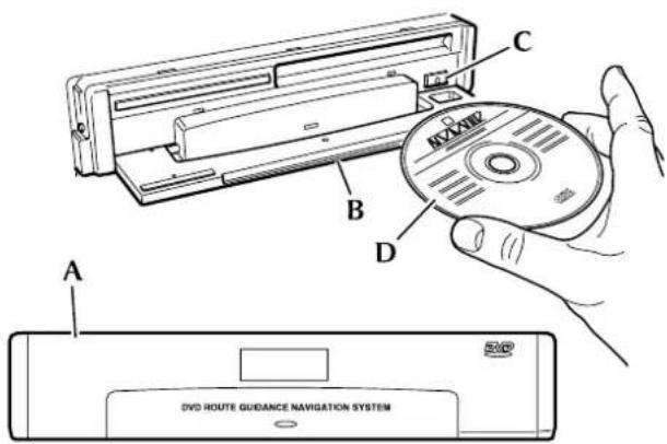
Loading the Map DVD
The ignition must be switched on (position I or II) and the radio must be switched on.
- Locate the navigation unit (
A), in the luggage compartment.
- Open the front cover (
B), using the recess on the top edge.
- If a DVD is already loaded, push the eject button (
C) to eject it.
- Load the DVD with the printed side upwards (moisture or foreign objects to enter the slot.
D). Do not allow
- Close the cover (
B).
Ensure that an audio CD is not loaded into the navigation unit and vice versa. (No damage will be done but the system will not operate.)
Using the System (continued)
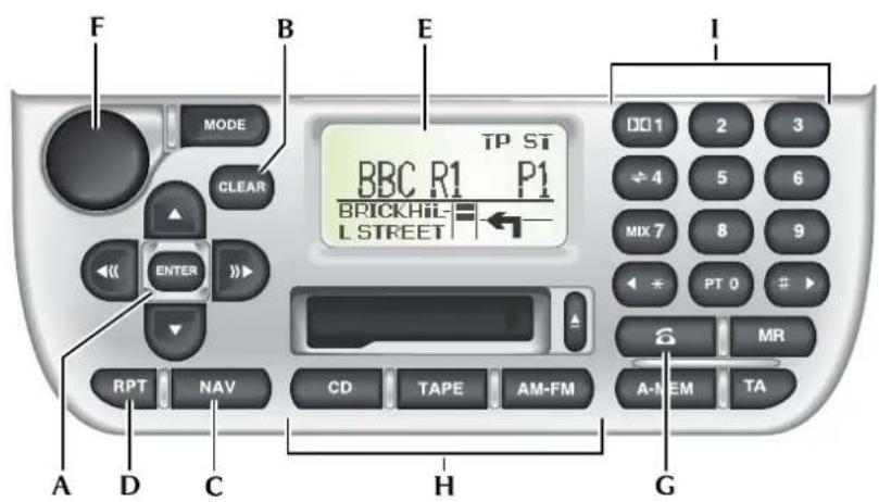
Control Panel
A. Cursor control and Enter button
B. Clear button
C. Navigation button
D. Repeat button
E. LCD display
F. On/Off and Volume control
G. Phone button
H. CD, Tape and AM-FM buttons
I. Key pad
Screen Displays
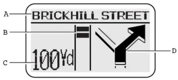
Full Screen Mode
In full screen mode (hybrid off), the whole screen displays information relating to the navigation system. A typical display is shown with a key to the main items of information.
A. Text area – Shows the next road name. Where applicable, the road number (without prefix letter) is shown in the top left corner.
B. Bar graph – The count-down bar graph is displayed when the vehicle is 300 yards (300 metres) from the next turn.
C. Next turn information – Shows the distance to the next turn and the current vehicle location. (While the bar graph is being displayed, the turn information is abbreviated.)
D. Next turn diagram – Shows a diagrammatic view of the next turn and indicates the action to be taken.
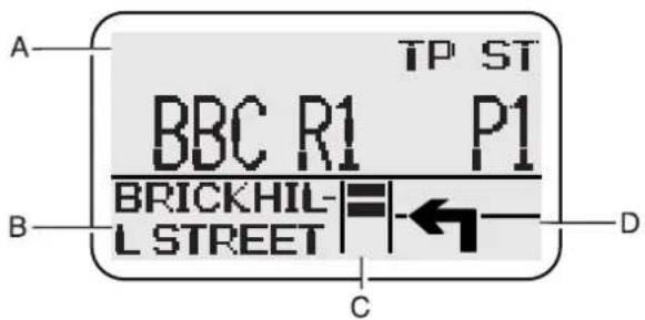
Split Screen Mode
In split screen mode (hybrid on), the upper portion of the screen displays information relating to the selected audio mode, and the lower portion to the navigation system. A typical display is shown with a key to the main items of information.
A. Audio systems information – Shows the sound system or phone display.
B. Text area – Shows the distance to the next turn and the current vehicle location. (While the bar graph is being displayed, the information is abbreviated.)
C. Bar graph – The count-down bar graph is displayed when the vehicle is 300 yards (300 metres) from the next turn.
D. Next turn symbol – Indicates the action to be taken at the next turn.
Scrolling Indicators
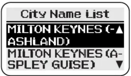
The vertical indicators, when displayed at the right-hand side of a text screen, show that more lines of information can be viewed by using the Cursor control (Up/Down).
Menu Screens
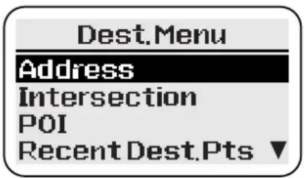
The screen shows the list of menu items.
Highlight the menu item required using the Cursor control (Up/Down) and push ENTER. (If the desired menu item is not being displayed, scroll the list as required.)
If a menu item cannot currently be selected, it is not displayed.
The complete menu structure is shown in the Quick Reference Guide supplied with this Owner's Guide
Using the Controls
The basic operation of the controls is shown below. For operation while under guidance, see 'Panel Controls'
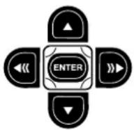
Cursor Control and Enter button
Cursor Control – The Cursor control comprises the four arrow buttons (Up, Down, Left and Right) and has the following functions according to the screen currently selected.
- Selects menu and text list items (Up/Down).
- Character/number selection on text input screens (Left/Right).
• Character deletion on text input screens, - Selects 'Search' on character and number input screens (Down).
Enter Button - The Enter button has the following functions.
- Confirms the last screen action (e.g. selection of a menu or text list item).
- Enters the selected character on text input screens.
• A c knowledges a screen prompt, e.g. NEXT, OK.
On/Off and Volume control
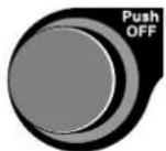
Push the control to switch the radio on. Push again to switch off. For operation of the Volume control, see 'Volume Adjustment'.
When the radio is switched off the navigation system remains initialised.
Navigation Button

Push NAV to select the navigation system. The road safety caution screen is displayed. If the system is not ready, the screen shows 'Please Wait' while initialisation takes place.
Before pushing NAV, the radio must be switched on using the On/Off and Volume control.
CD, Tape and AM-FM Buttons

Push the appropriate button to select the desired sound system source. (Push NAV to return to the navigation system.) For operation while under guidance, see 'Panel Controls'.
Using the Controls (continued)
Phone Button

Selects phone mode. (Push NAV to return to the navigation system.) For operation while under guidance, see 'Panel Controls'.
Repeat Button

While under guidance, repeats the last audible instruction. If the manoeuvre point has been passed, the audible instruction for the next manoeuvre point will be heard.
Clear Button

Returns to the previous menu, character input, or text screen.
Volume Adjustment
The sound output during voice guidance can be adjusted as described below. The current setting is displayed during the adjustment procedure.
'Mute' – Mutes voice guidance.
'-3' to '+3' – Changes the sound volume, from minimum ('-3') to maximum ('+3').
'Max' - Mutes audio sound during voice guidance.
Navigation sound will be heard from the front speakers only.
During voice guidance, the audio sound will be heard at a preset level (unless muted).
During voice guidance, the audio sound from the rear speakers will be limited to volume setting 15.
The procedure for changing the setting is as follows:
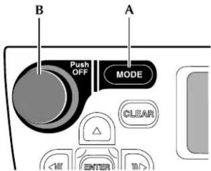
-
Push MODE ( A) until the display shows 'NAV Audio'.
-
The current setting is displayed.
-
Turn the Volume control ( B) until the desired setting is shown. (The normal audio display resumes automatically, or when any sound system button is pushed.)
Character Input
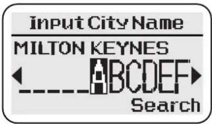
Highlight the first character in the name using the Cursor control (Left/Right) and push ENTER. Repeat for each character in turn. As characters are entered, only the characters available to complete the name (or similar names) are shown.
After entering all the characters required, highlight 'Search' using the Cursor control (Down) and push ENTER. A list of possible names is shown on the screen,
Character Deletion
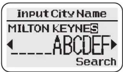
To delete one or more characters, push the Cursor control (Up). The last character input is shown highlighted. Push the Cursor control (Left) to delete each highlighted character in turn. To continue, push the Cursor control (Down).
Selection Screen Example
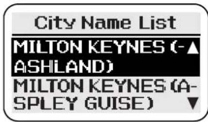
The screen shows the list of possible names from the characters entered. Highlight the item required using the Cursor control (Up/Down) and push ENTER. The next screen is displayed.
The list may continue on further pages. The required item can be selected by using the Cursor control (Up/Down).
Number Input
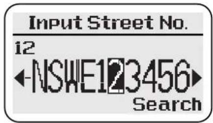
Highlight the first digit in the number using the Cursor control (Left/Right) and push ENTER. Repeat for each digit in turn.
When all the digits have been entered, Highlight 'Search' using the Cursor control (Down) and push ENTER. The next screen is displayed.
Number Deletion
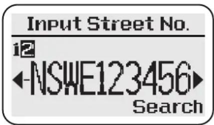
To delete one or more digits, push the Cursor control (Up). The last digit input is shown highlighted. Push the Cursor control (Left) to delete each highlighted digit in turn. To continue, push the Cursor control (Down).
Numbers can also be input using the key pad. (Push ENTER to select.) If a house number is not required, highlight 'Search' and push ENTER. If the number is not in range, a warning message will be displayed. (If the number is not known, highlight ENTER and push ENTER.)
Memory Points
These are map locations that can be stored in memory by the user with a personalised name tag (e.g. Doctor, Office) for subsequent selection as route destinations or way points. The following input methods can all be used to store memory points: address, intersection, points of interest, recent destinations and local points. See the 'Destination' menu. The current vehicle location can also be stored as a memory point, see the 'Options' menu.
Way Points
Way points are held in a list and can be used to divide a route into a number of sections; the route being calculated one section at a time. The user selects the first and last way points to be visited along the route. The order in which the intermediate way points are visited is determined during route calculation, based on the current calculation method (e.g. Shortest Time). Before using the feature, the desired locations have to be added to the way points list. Up to a maximum of 8 way points can be stored.
Using way points - The procedure for setting a route using way points is shown below.
- Enter the desired way point addresses.
- Select the way points to be visited first and last along the route. (The last way point is the ultimate destination.) Then set the route to the first way point.
- After driving each section of the route, to set the route to each following way point, select 'Next Way Point'.
- One or more way points may be deleted from the list if required.
Avoid Roads
After setting up a route, one or more roads can be selected, from the route turns list, as roads to be avoided. The route is then recalculated avoiding the roads selected.
Points of Interest (POI)
This is a database of useful names and addresses held on the map DVD. The information can be displayed on the screen and sorted by category. A POI can be selected from the list and used as a route destination, memory point or way point.
Local points - This allows a POI category to be displayed sorted by distance from the current vehicle location, and provides a quick method of selecting points of interest near at hand.
Voice Guidance
One or more audible instructions and/or chimes will be heard for each manoeuvre point along the route. Three levels of guidance are available (minimum, normal, and maximum) which are selected from the Setup menu, see 'Voice Prompt'.
Voice guidance will be muted while a phone call is in progress.
Screen Guidance
As the route is followed, the current vehicle location, and next turn information, are displayed.
Typical Example - Introduction
This is a simple example showing how to use the basic features of the system to set a route. It describes each screen in turn and explains how to use the controls. For information relating to the other features of the system, see the relevant section in the handbook.
Before using the system, check that the correct map DVD is loaded, see 'Loading the Map DVD'.
Initialisation
The navigation system is initialised when the radio is switched on.
Push NAV to select the navigation system. The road safety caution screen is displayed. If the system is not ready, the screen shows 'Please Wait' while initialisation takes place.
IMPORTANT
Please wait
Initialising the system
Road Safety Caution
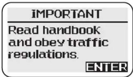
The caution screen shows the following information.
IMPORTANT: Read handbook and obey traffic regulations.
To use the system, push ENTER. The screen shows the Navigation menu.
Navigation Menu
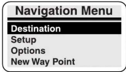
The screen shows the Navigation menu options:
- Destination
- Setup
- Options
- New Way Point (only when way points entered)
To display the Destination menu, highlight 'Destination' using the Cursor control (Up/Down), and push ENTER.
Destination Menu
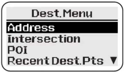
The Destination menu is displayed, showing the methods available for entering a destination.
To input an address, highlight 'Address' using the Cursor control (Up/Down), and push ENTER.
Enter the destination with the engine running. If a destination is entered while the engine is not running, the data will be lost when the engine is started. (If this occurs, the destination details can be retrieved from the list of recent destinations.)
Address Input
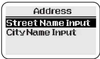
To input the required street name, highlight 'Street Name Input' using the Cursor control (Up/Down), and push ENTER.
Street Name Input
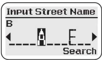
The character input screen is displayed for input of the street name required. (Only the first few letters of the name need to be entered.)
After highlighting 'Search' and pushing ENTER, a list of possible streets is displayed. Highlight the street required using the Cursor control (Up/Down) and push ENTER for input of the house number.
Enter the name of the street only. (Do not include 'Street', 'Road' or other similar word.)
House Number Input
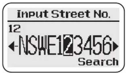
The number input screen is displayed for input of the house number required.
After highlighting 'Search' and pushing ENTER, a list of possible cities is displayed.
Notes:
If the number is not in range, a warning message 'INVALID NUMBER' will be displayed. (If the number is not known, highlight ENTER and push ENTER.)
If the street does not have house numbers held on the map DVD, the number input screen will not be shown.
Select City
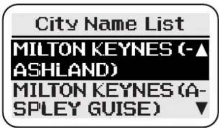
The list includes all the cities and districts where the address input (house number and street) occurs.
Highlight the city & district entry required using the Cursor control (Up/Down). Push ENTER to display the location and confirm the destination.
Confirmation
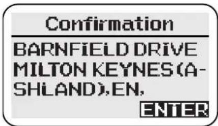
The screen shows the location details of the address input. To continue, push ENTER. To confirm the destination, highlight 'ENTER to Proceed' using the Cursor control (Up/Down), and push ENTER to calculate the route.
Route calculation – The screen shows 'Calculating' while the route is being calculated. When the calculation is complete, the screen shows the guidance display.
Pushing CLEAR while the screen shows 'Calculating' will cancel the calculation.
Route Guidance
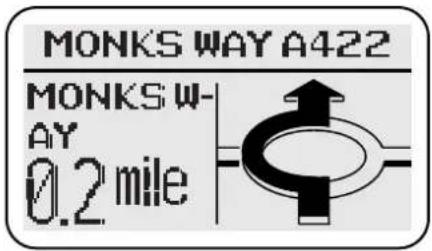
Drive off, following the voice guidance given by the system, until the destination is reached.
If the vehicle is not on a digitised road at the start of the route, the screen will show 'Please Proceed' and the destination compass heading, until the route is reached.
End of Route
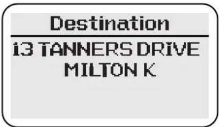
As the vehicle approaches the end of the route, 'DESTINATION' is shown on the screen. This is confirmed by voice guidance. After arrival at the destination, the screen shows the destination address. To continue, and select the Navigation menu, push CLEAR or NAV. (Alternatively, one of the audio source buttons may be pushed.)
End of worked example.
Menu Summary
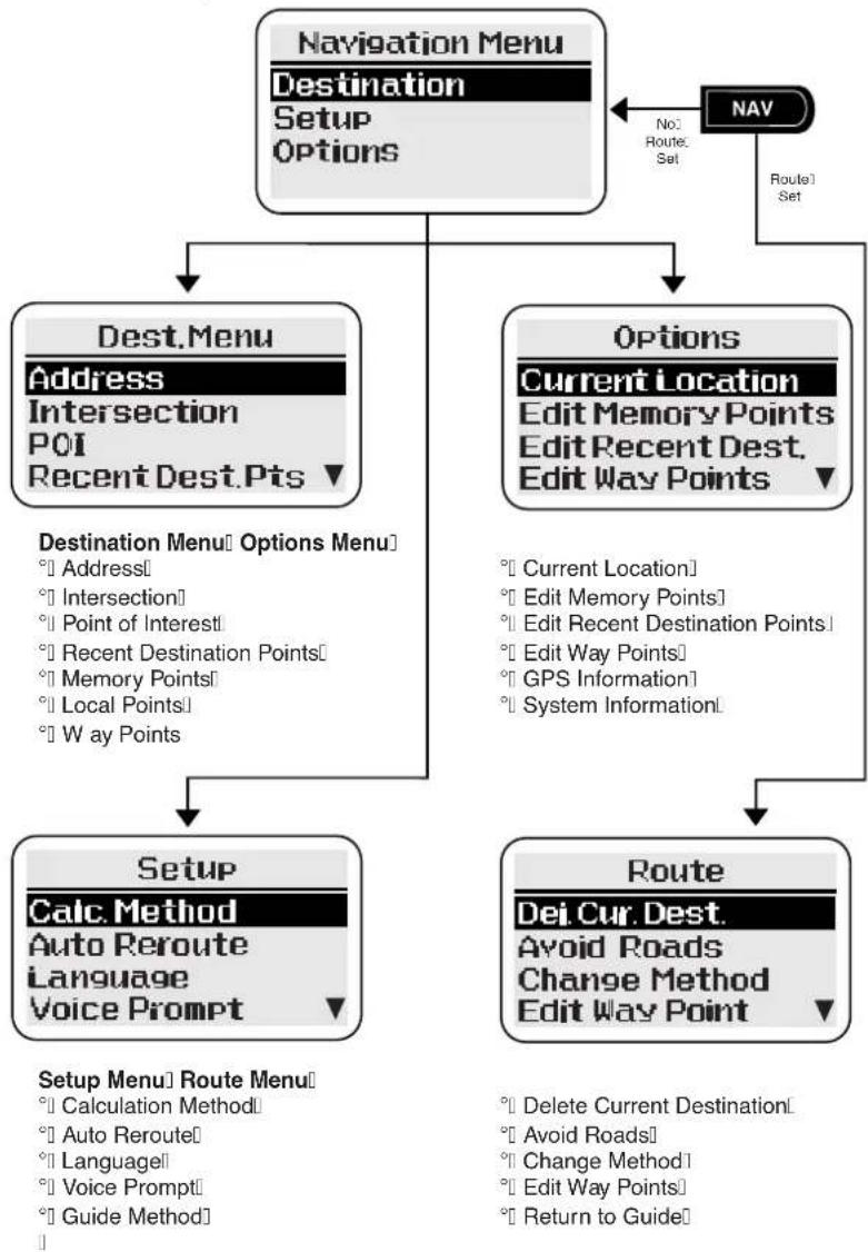
flowchart
graph TD
    A["Navigation Menu\nDestination\nSetup\nOptions"] --> B["Dest.Menu\nAddress\nIntersection\nPOI\nRecent Dest.Pts ▼"]
    A --> C["Options\nCurrent Location\nEdit Memory Points\nEdit Recent Dest.\nEdit Way Points ▼"]
    B --> D["Destination Menu Options Menu\n° Address\n° Intersection\n° Point of Interest\n° Recent Destination Points\n° Memory Points\n° Local Points\n° Way Points"]
    C --> E["Route\nDef. Cur. Dest.\nAvoid Roads\nChange Method\nEdit Way Point ▼"]
    D --> F["Setup\nCalc. Method\nAuto Reroute\nLanguage\nVoice Prompt ▼"]
    E --> F
    F --> G["Setup Menu Route Menu\n° Calculation Method\n° Auto Reroute\n° Language\n° Voice Prompt\n° Guide Method"]
    A --> H["NAV\nNo:\nRoute: Set\nRoute1 Set"]
If the desired menu item is not displayed, scroll the screen using the Cursor control (Up/Down).
Initialisation
IMPORTANT
Please wait
Initialising the system
The navigation system is initialised when the radio is switched on.
Push NAV to select the navigation system. If the system is not ready, the screen shows 'Please Wait' while initialisation takes place.
Road Safety Caution
IMPORTANT
Read handbook and obey traffic regulations.
ENTER
When the system is ready, the caution screen will be displayed.
To continue and use the system, push ENTER. The screen shows the Navigation menu.
If route guidance was in progress when the ignition was switched off, a prompt is displayed.
Navigation Menu
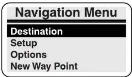
The Navigation Menu is displayed by pushing NAV. Select the option required:
- Destination
- Setup
- Options
- New or Next Way Point
These options are described in the following pages.
Next Way Point
When using way points, select this option to calculate the route to the next way point in the list, using the current calculation method.
Some of the options from the Destination menu are not available while driving (not under guidance). These are 'Address', 'Intersection' and 'Points of Interest'.
The Setup and Options menus are not available while driving (whether under guidance or not).
The Route menu is only available while driving under guidance.
'Next Way Point' is only available after a way point has been entered in the way point list.
Destination Menu
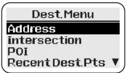
Select the option required:
- Address
- Intersection
- P oints of Interest
- Recent Destination Points
- M emory Points
- Local Points
- Way Points
These options are described in the following pages.
For destinations outside the detailed map area, see 'Long Haul areas'.
While driving under guidance, none of the options on the Destination menu are available.
Destination Menu (continued)
Address
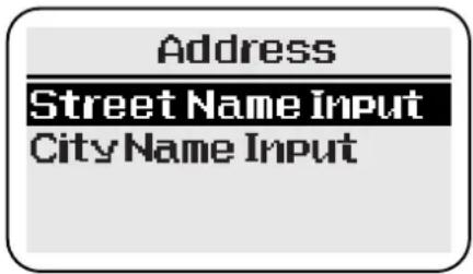
Select the option required:
Street name input – Input and select the street name, followed by the house number. Select the address required from the options displayed. The screen shows the location details of the desired address,
City name input – Input a city name, and select the city (or city and district), followed by the street name details, see above.
Note: The system defaults to the city where the vehicle is located.
Intersection
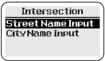
Select the option required:
Street name input – Input and select the street names forming the intersection. Select the intersection required from the options displayed. The screen shows the location details of the desired intersection.
City name input – Input a city name, and select the city (or city and district), followed by the street name details, see above.
Note: The system defaults to the city where the vehicle is located.
Points of Interest (POI)
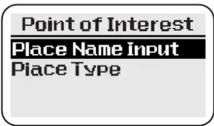
Select the option required:
Place name input – Input the desired name and select the item required from the POI list displayed (e.g. 10 Downing Street).
Place type – Select an item from the list of categories displayed (e.g. Airport). (If necessary, select an item from the list of sub-categories displayed). Input a city name, and select the city (or city and district), followed by the name of the POI required.
The screen shows the location details of the desired point.
Destination menu (continued)
Recent Destination Points
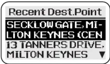
Select the item required from the list of recent destinations displayed. The screen shows the location details of the selected point.
A maximum of 20 recent destinations can be stored. When this number is exceeded, the oldest destination in the list is deleted each time a destination is set. If the same destination has been set more than once, it will only appear once in the list.
Memory Points
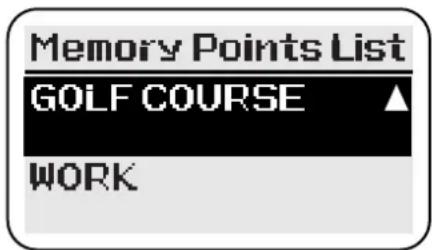
Select the item required from the list of memory points displayed. The screen shows the location details of the point selected.
A maximum of 90 memory points can be stored. When this number is exceeded, the point at the bottom of the list is deleted each time a new point is entered.
Local Points
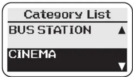
Select an item from the list of POI categories displayed. The screen shows the list of points of interest in that category, sorted by distance from the current vehicle location. Select the point required. The screen shows the location details of the point selected.
Way Points
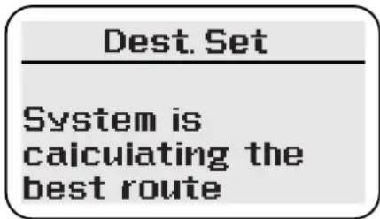
Note: Before using this procedure, the desired locations must be entered and added to the way points list.
The screen briefly shows 'System is calculating the best route'. The screen then shows 'Confirm Destination', with the first way point location details. Select the option required from the list displayed:
ENTER to proceed – When the desired first and last way points have been chosen, select this option to set the route to the first way point.
Way points list – This option is used to set the first and last way points for the current route. Select an item from the list of way points displayed and push ENTER. Follow the on-screen prompts as required.
Setup Menu
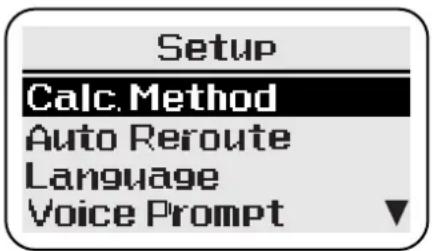
Select the option required:
• Calculation Method
- A uto Reroute
- Language
- V oice Prompt
- Guide Method
These options are described in the following pages.
Calculation Method
Select the option required:
- Shortest Time
• M aximise Motorways
• M inimise Motorways
• M inimise Toll Roads
The desired guidance method can be selected to optimise route calculation as required. Only one method can be selected.
Push CLEAR to continue without change.
Auto Re-route
Select the option required:
- Yes
- No
If Auto Re-route is selected, and the vehicle deviates from the calculated route, the route will automatically be recalculated. If Auto Re-route is not selected, the route will not be recalculated, but guidance will resume if the vehicle rejoins the original calculated route.
Push CLEAR to continue without change.
Language
Select the language required:
- English
- Deutsch (German)
• F r ançais (French) - Italiano (Italian)
- Nederlands (Dutch)
The language used for the on-screen text and voice instructions can be selected from the list displayed.
Push CLEAR to continue without change.
After changing the language, the road safety caution is displayed in the new language. Push ENTER to continue. If the vehicle is in a long-haul area, a second caution will be displayed.
Voice Prompt
Select the option required:
• M in.
- Normal
• M ax.
The desired number of audible instructions given for each manoeuvre can be chosen. The actual number of instructions given will vary according to the particular route being followed.
Push CLEAR to continue without change.
Guide Method
Select the option required:
- Hybrid On
- Hybrid Off
The appearance of the display while under guidance can be chosen as follows.
Hybrid On – The display is normally in split screen mode. Just before each manoeuvre point, the display changes to full screen mode.
Hybrid Off – The display is normally in full screen mode.
If one of the audio buttons is pushed and the display is in full screen mode, the display will change briefly to split screen mode to allow audio adjustments.
Options Menu
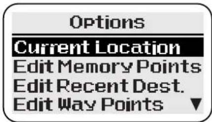
Select the option required:
- Current Location • Edit Way Points
- Edit Memory Points • GPS Information
- Edit Recent Destination Points • System Information
These options are described in the following pages.
Current Location
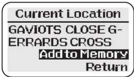
Note: If the vehicle is in a non-digitised area, route guidance will not be given to the exact location. Position the vehicle as near to a public road as possible.
The screen shows the current vehicle location which may be stored as a memory point. Select the option required from the list displayed:
Add to Memory – The screen shows 'Location may not be on a road. Proceed?'. Select 'YES' to confirm, see Name tag entry, or 'NO' to redis- play the previous screen.
Return – Redisplays the Options menu.
Name Tag
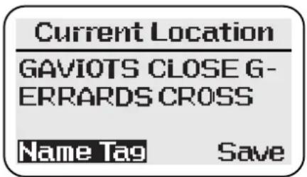
Name tag entry – The details of the current vehicle location are confirmed on the screen. Select the option required from the list displayed:
Save – Push ENTER to confirm and redisplay the Options menu. (The location is stored without a name tag.)
Name Tag – Input the desired name. Select 'Save'; the name tag and location details are displayed. Push ENTER to confirm and redisplay the Options menu.
Edit Memory Points
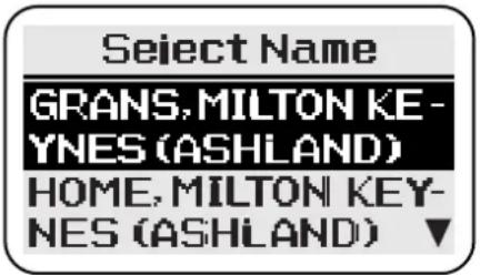
Select the item required from the list of memory points displayed. The screen then shows the following options, select the option required:
Change Name – The character input screen is displayed to change the name. When completed, select SAVE.
Delete – Select 'YES' or 'NO' as required.
Push CLEAR to continue without change.
Edit Recent Destination Points
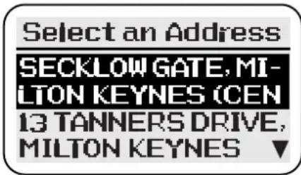
This function allows an item to be deleted from the list of recent destination points.
Select the item required to be deleted from the list of recent destination points displayed. The screen shows 'Delete this Point'. Select 'YES' or 'NO' as required.
Edit Way Points
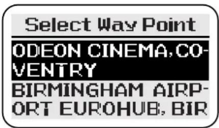
The screen shows the list of current way points. One or all of the way points can be deleted. Select the way point required and follow the on-screen prompts as necessary.
GPS Information
GPS Information
Current Location
Current Position
Satellites
Select the information required:
- Current Location
- Current Position
- Satellites
The following information can be displayed: current vehicle location, current vehicle position (latitude, longitude and elevation), and the number of satellites in contact with the system. Push ENTER to continue.
System Information
System Info.
Database Area
Database Code
Software Version
Select the information required:
- Database Area
- Database Code
- Software Version
Push ENTER to continue.
Route Calculation and Guidance
Confirm Destination
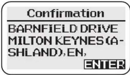
The confirmation screen shows the location details of the required address or point. To continue, push ENTER. Select the option required from the list displayed:
ENTER to proceed – Select this option to set a route, with the chosen location as the destination.
Memory point set – Select this option to save as a memory point. The character input screen is displayed. Input the name required for the point, and select 'Save'. The confirmation screen is displayed again.
Add way point – Select this option to save as a way point. The list of current way points is displayed. Push ENTER to add the chosen location; the Destination menu is displayed.
Continue Trip
If the vehicle has been stopped and the ignition switched off while under guidance, when the ignition is switched on again the screen will show the destination details (after the road safety caution screen). Push ENTER to continue guidance.
Push CLEAR if guidance for the remainder of the route is not required. The route will be cancelled and the Navigation menu will be displayed.
Calculation
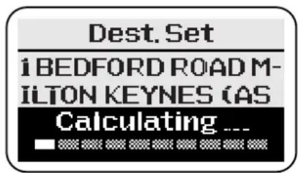
The screen shows 'Calculating' and the destination details while the route is being calculated. When the calculation is complete the first route instruction is displayed.
If the destination is located on a restricted or private road, a warning message will be displayed.
Pushing CLEAR while the screen shows 'Calculating' will cancel the calculation.
Route Guidance
Driving Off
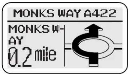
Only operate, adjust or view the system when it is safe to do so.
The screen shows the current vehicle location and the first turn diagram. As the route is followed, current vehicle location, distance to the next turn and next turn diagram are displayed.
Drive off, following the voice guidance given by the system until the destination is reached. The screen shows the destination symbol.
If the vehicle is not on a digitised road at the start of the route, the screen will show 'Please Proceed' and the destination compass heading, until the route is reached.

Destination symbol – Indicates the current route destination.
Panel Controls
While the vehicle is under guidance, the main functions of the panel controls are as shown below.
Cursor control – The Cursor control has the following functions (full screen mode only).
- Displays the turns list (Left or Right).
- Displays the turn diagrams in sequence (Up, followed by Up/Down).
Enter button – Displays the route guidance summary (full screen mode only).
Navigation button – The Navigation button has the following functions.
- In split screen mode, selects full screen.
- In full screen mode, selects the Route menu.
Repeat button – Repeats the last audible instruction. If the manoeuvre point has been passed, the audible instruction for the next manoeuvre point will be heard.
Clear button – At the end of a route, selects the Navigation menu (full screen mode only).
Audio source buttons – Operate as required to make audio adjustments or to use the in-car telephone. (If the display is in full screen mode, it will change briefly to split screen mode.)
On/Off and Volume control – Push the control to switch the radio off. Push again to switch on. A message will be displayed asking you whether the current route guidance is to be continued.
Screen Guidance
Full Screen Mode
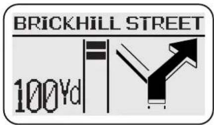
With the guide method set to Hybrid Off, the whole screen displays information relating to the navigation system. If one of the audio buttons is pushed while under guidance, the display will change briefly to split screen mode.
The guide method is selected from the Setup menu.
Split Screen Mode
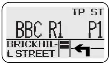
With the guide method set to Hybrid On, the upper portion of the screen displays information relating to the selected audio mode, and the lower portion to the navigation system. Just before each manoeuvre point, the display changes to full screen mode.
Route Menu
Route
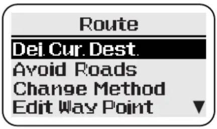
Select the option required:
- Delete Current Destination
- A v oid Roads
- Change Method
- Edit Way Points
- Return to Guide
These options are described in the following pages.
The Route menu is accessed by pushing NAV. It is only available after a route has been set.
Select 'Return to Guide' to leave the Route menu and resume guidance mode.
Delete Current Destination
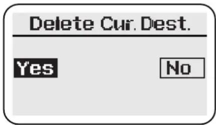
Select the option required:
- Yes - No
If 'Yes' is selected, the current route will be cancelled.
Avoid Roads
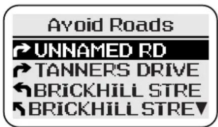
Select the item required from the list of turns displayed. Select the option required from the list displayed:
Re-route - When the desired road(s) have been chosen, select this option to recalculate the route.
Continue to Avoid Roads – The turns list is displayed again to select another road to be avoided.
Route Menu (continued)
Change Method
Change Method
Shortest Time
Maximise Motorway
Minimise Motorways
Minimise Toll Roads
Select the option required:
- Shortest Time
• M aximise Motorways
• M inimise Motorways
• M inimise Toll Roads
The one of the calculation methods can be selected to optimise route calculation as required. After selection, the route is recalculated.
Push CLEAR to continue without change.
Edit Way Points
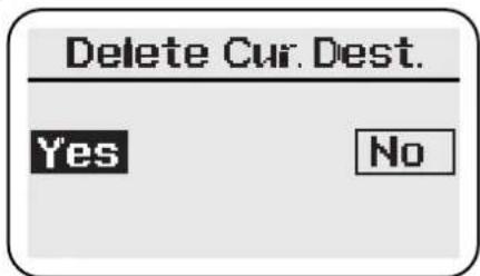
Select the option required:
- Yes
No
If 'Yes' is selected, the current section of the route will be cancelled.
Additional Guidance Features
Turns List
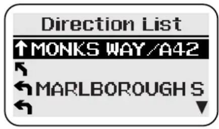
The list of turns on the current route is displayed by using the Cursor control (Left or Right). The location of the turn, action to be taken, and distance to the next turn are shown.
Use the Cursor control (Up/Down) to scroll through the list. At the end of the list, the destination details are shown.
To continue push ENTER.
Route Guidance Summary
The route guidance summary is displayed by pushing ENTER (full screen mode only).
The summary includes the following information.
- Current compass heading to destination.
- Remaining distance to destination.
• Estimated time to destination. - Destination address details.
Areas Where Guidance is Not Possible
If the vehicle is in an area which is not on the database (not on a digitised road), a message will be displayed. Guidance will resume automatically when the vehicle returns to a digitised area.
Long-Haul Areas
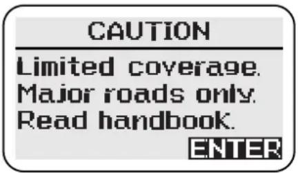
A long-haul area is an area (or country) outside the detailed coverage area of the map disc currently loaded in the navigation unit.
This caution message is displayed when the system recognises that the vehicle is in a long-haul area. It is also displayed each time the system is turned on while the vehicle remains in a long-haul area, and when the screen language is changed.
Route Guidance
In long-haul areas, only the major road networks are covered by the system. Normal route guidance is available, provided that the vehicle keeps to the major roads.
If the vehicle leaves the route, recalculation will not be possible away from the major road network. If a route is recalculated, limitations in the map data may result in an unnecessary detour back to the original route being made.
Destination Setting
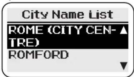
Select 'Address' from the 'Destination' menu, and enter a city name. In the list displayed, cities in long-haul areas are shown with 'City Centre' after the city name. The complete list of long-haul cities is included at the end of this section.
Select the city required. The screen briefly shows 'Only city centre available'. The screen then shows the details of the city selected.
Destinations within long-haul areas cannot be set to an exact street location by the address entry method described above.
Destinations may also be set by selecting a POI rest area.
Selecting Stored Destinations
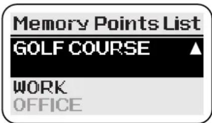
Owing to limitations in the digitised map data, it may not always be possible to set a destination in a long-haul area using a previously stored location (e.g. recent destination or memory point). This can occur when the location was originally stored while the detailed map disc for that area was loaded.
Any items that are currently unavailable are shown shaded when the list is displayed. If a shaded item is selected a message is shown briefly on the screen.
Rest Areas
Details of rest areas (e.g. motorway service areas and car parks) can be seen by selecting the 'Rest Area' category of Points of Interest (or Local Points). All the long-haul areas covered by the system are included, and a rest area can be selected as a destination.
Rest area details – All rest areas are listed, sorted by distance from the current vehicle location. The details for each area include the motorway (where applicable), and the country in which the rest area is situated.
In long-haul areas, 'Rest Areas' is the only Points of Interest category available.
Long-Haul Cities
This list of long-haul cities includes all the countries covered by the system. Ignore the country, or countries, covered by the map disc that is currently loaded, as normal route guidance will be available.
Austria France France (cont'd) Germany Germany
| Bregenz Amiens Metz Augsburg Mönchengladba | (cont'd)ch | |||
| Dornbirn (Rheintal) | Angers Monaco | (Monaco) | Freiburg im Breisgau | Münster |
| Graz Annecy Montbeliard Karlsruhe Oberhausen | ||||
| Innsbruck Avignon Monte-Carlo | (Monaco) | Mannheim | Solingen | |
| Klagenfurt | Bayonne | Montpellier | München | Wuppertal |
| Linz | Besançon | Mulhouse | Nürnberg | Bremen |
| Salzburg | Bethune Nancy | Stuttgart | Hamburg | |
| St. Pölten | Bordeaux | Nantes | Darmstadt | Hannover |
| Vienna | Brest Nice | Frankfurt am Main | Kiel | |
| Villach | Caen | Nimes | Kaiserlautern | Berlin |
| Wels Calais | Orleans | Kassel | Chemnitz | |
| Cannes | Paris | Koblenz Dresden | ||
| Belgium Chambery | Pau | Ludwigshafen am Rhein | Erfurt | |
| Antwerpen | Clermont-Ferrand | Perpignan | Mainz | Leipzig |
| Arlon | Dijon | Poitiers | Saarbrücken | Magdeburg |
| Brugge | Douai | Reims | Weisbaden | Potsdam |
| Brussel | Dunkerque | Rennes Aachen | Rostock | |
| Charleroi | Grenoble | Rouen | Bielefeld | Schwerin |
| Gent | Hagondange | Saint-Etienne | Bochum | Weimar |
| Hasselt Le Havre | Saint-Nazaire | Bonn | ||
| Leuven Le Mans | Strasbourg | Dortmund | ||
| Liege | Lens | Thionville | Duisburg | |
| Mechelen | Lille | Toulon Düsseldorf | ||
| Mons | Limoges Toulouse | Essen | ||
| Namur | Lorient | Tours | Gelsenkirchen | |
| Oostende | Lyon | Valence | Köln | |
| Wavre | Marseille | Valenciens | Krefeld | |
| Menton | Leverkusen | |||
| Italy Italy (cont'd) Netherlands | United Kingdom | United Kingdom (cont'd) | ||
| (cont'd) | ||||
| Bari Salerno Hertogenbosch Aberdeen Northampton | ||||
| Bergamo Taranto Leeuwarden Bath Norwich | ||||
| Bologna Terni Leiden Birmingham Nottingham | ||||
| Bolzano Torino Lelystad | Bradford | Oxford | ||
| Brescia | Trento | Maastricht | Brighton | Peterborough |
| Ferrare | Trieste | Middelburg | Bristol | Plymouth |
| Firenze | Varese | Nijmegen | Cambridge | Portsmouth |
| Foggia Venezia | Rotterdam | Cardiff Reading | ||
| Forli | Verona | Tilburg | Carlisle Sheffield | |
| Genova | Vicenza | Utrecht | Coventry | Southampton |
| Latina | Vatican City | Zaanstad | Derby | Stoke on Trent |
| Lecce | San Marino | Zoetermeer | Dover | Sunderland |
| Livorno | Zwolle | Dundee | Swansea | |
| Milano | Luxembourg | Edinburgh | Wolverhampton | |
| Modena | Luxemburg | Switzerland | Exeter | York |
| Monza | Basel | Fishguard | ||
| Napoli | Netherlands | Bern | Folkstone | |
| Novara | Almere | Biel | Glasgow | |
| Padova | Amersfoort | Geneve | Harwich | |
| Parma | Amsterdam | Lausanne | Holyhead | |
| Perugia Apeldoorn | Lugano Inverness | |||
| Pescara Arnhem | Luzern | Ipswich | ||
| Piacenza | Assen | Neuchatel | Kingston upon Hull | |
| Pisa Breda | St. Gallen | Leeds | ||
| Prato | Den Haag | Winterthur | Leicester | |
| Ravenna | Dordrecht | Zug | Liverpool | |
| Reggio Calabria | Eindhoven | Zürich | London | |
| Reggio Emilia | Enschede | Manchester | ||
| Rimini | Groningen | Liechtenstein | Middlesbrough | |
| Roma | Haarlem | Vaduz | Newcastle upon Tyne | |
Contents
Service Bulletin/Campaign/Recall Record 3-A-1
Service Schedules Summary 3-A-2
Pre-delivery Inspection 3-A-3
Service Schedules 3-A-5
Vehicle Identification 3-A-8
Pre-delivery Inspection 3-A-8
Service Records 3-B-1
Service Bulletin / Field Action / Recall Record
| Campaign No. Date | Dealer Name | |
Service Bulletin / Field Action / Recall Record (continued)
| Campaign No. Date Dealer Name | |
Service Schedules Summary
Aston Martin Vanquish should be serviced every 12,000 km (7,500 miles) or 6 months, whichever occurs first. The service schedules cover:
Pre-delivery Inspection
This free series of checks is carried out on the car by the Selling Dealer before delivery. The checks ensure that you receive a vehicle which matches the high quality standards set by Aston Martin Lagonda Limited.
Initial 1,500km (1,000 mile) Service
The Selling Dealer is responsible for the costs and work involved in performing this free service. The initial service consists of an inspection and fluid levels check after completion of the first 1,500 km (1,000 miles) and includes fine adjustments to compensate for initial 'bedding-in' e.g. handbrake adjustment. Also, engine oil and filter will be changed to clear any contaminants picked up during the initial running.
12,000 km (7,500 mile) Service
This is the basic service interval for V12 Vanquish when consumable oils, filters, etc will be changed and functional checks will be carried out on all major systems in the vehicle.
24,000 km (15,000 mile) Service
In addition to the 12,000 km (7,500 mile) service items, air filters, wiper blades etc. are renewed at 24,000 km (15,000 mile) intervals.
48,000 & 96,000 km (30,000 & 60,000 mile) Services
Again the basic 12,000 km (7,500 mile) service is carried out together with the additional checks and replacement items shown in the following schedules.
2 Years
To maintain the hydraulic brake system performance, the brake fluid is renewed every 2 years to clear the system of absorbed water vapour.
Pre-delivery Inspection
Before you receive your V12 Vanquish, it will undergo a comprehensive pre-delivery inspection at the Dealer's premises to ensure that it meets Aston Martin's quality standards. The following checks will be made:
Levels and Leaks
Engine oil
Power steering oil
Brake Fluid
Engine coolant level
Engine coolant specific gravity
Windscreen washer fluid
Fuel system
Gearbox oil
ASM/SSM Gearshift Oil
Rear axle oil - Differential
Battery (under rear parcel shelf/seat)
Mechanical Functions
Gear selection
Clutch operation
Throttle pedal operation
Parking brake operation
Steering column adjustment
Steering lock operation
Seat adjuster rails
Bonnet (Hood) release and catch
Door operation and locks
Storage compartments
Rear view mirror
Boot (Trunk) release and latching
Wheels and Tyres
Road wheel nuts
Tyre pressures
Front wheel tracking
Tyre Orientation (rotation arrows)
Electrical Checks
Battery condition
Heated front & rear screens
Windscreen washers
Windscreen wipers
Air-conditioning controls
Gauges and warning lights
Radio / Cassette / CD player
All speakers
Inertia switch
Window mechanisms
Side and headlights (main and dip)
Front fog lights
Rear fog lights (where fitted)
Hazard warning lights
Instrument illumination and dimmer
Air conditioning panel illumination
Horns
Interior/map lights in rear view mirror
Cigar lighter
Seat adjustment - all functions
Door mirror adjustments
Reset clock (if necessary)
Door / boot courtesy lights
Central locking system
Filler flap lock operation
Seat belt operation
Seat belt warning system
Security system / Remote control
Brake pedal start inhibit
Interrogate DTC codes
Check battery disconnect switch operation
Record battery open-circuit voltage
Tyre Pressure Sensing
ASM-SSM Function
V12 Vanquish Service Schedules
| Road Test | Final Checks |
| Engine | Drive belt tensioner operation |
| Clutch | Fuel / brake pipe security |
| Transmission | Fuel / fluid leaks |
| Rear axle differential | Cooling systems hose security |
| Steering | Exhaust catalyst security |
| Brakes | |
| Wheel balance | Hand-over Preparation |
| Dampers | |
| Noise vibration or harshness | Assemble / Check function of all keys and key fobs |
| Air conditioning performance | |
| Instruments operation | Clean bodywork |
| Seat belt and buckle operation | Clean off all transit labels |
| Steering wheel alignment | Valet Vehicle |
| Traction control | Degrease windscreen (windshield) |
| Gear change operation in all modes: | Fit carpets |
| Wheel Slip Protection | Remove interior protection |
| Auto | Check Owner's Guide/Quick Guide |
| Reverse | Install licence plates |
| Sport | Check for tyre inflation aerosols |
| Check for towing eye |
Service Schedules
The following service schedules are recommended for V12 Vanquish. The schedules may be modified if necessary. Please consult your Aston Martin Dealer for details of any service schedule updates.
Road Test Evaluation
1000mls 7500mls 15000mls
3 months 6 months 12 months
X X
X
Pre-Maintenance Road Test Evaluation
Fluids Filters and Leaks Checks
1000mls 7500mls 15000mls
3 months 6 months 12 months
X X
X X
X X
- -
X X
[Non-Text]
- -
- -
X -
- X
every 150000
X X
X X
every 60000
X X
Every 2 years 30,000 miles
X X
X X
X X
X X
X X
X X
X X
X X
X X
X X
X X
x
Renew the engine oil
x
Renew the engine oil filter
X
Check for engine oil leaks
x
Renew the air cleaner element
X
Check gearbox for leaks.
Top-up if necessary
- Renew gearbox oil (Filled for Life)
x Renew rear axle oil
- Check / top-up rear axle oil
- Check rear axle for leaks, top up if necessary
Renew engine coolant - check S. Gravity
x Check/top-up engine coolant
x Check cooling and heating systems for leaks
Renew fuel filters
x Check for fuel leaks
Renew brake fluid
x Check / top-up brake fluid reservoir
x Check / top-up ASM fluid reservoir
x Check / top-up power steering reservoir
x Check power steering system for leaks
x Check ASM system for leaks
x Check brake hoses, pipes and unions for leaks
x Check suspension dampers for leaks
x Top-up windscreen washer reservoir
x Check exhaust system for leaks
x Check exhaust bypass valve operation
x Check air conditioning system for leaks
Mechanical Function Checks
| 1000mls 7500mls 15000mls | |||
| 1500km 12000km 24000km | |||
| 3 months 6 months 12 months | |||
| - | x | x | Lubricate all door locks and hinges |
| x | x | x | Check / adjust polyvee drive belt tension,renew if necessary |
| x | x | x | Lubricate handbrake links and cables |
| x | x | x | Check handbrake security |
| - | - | 30,000 Check condition of handbrake pads | |
| - | x | x | Inspect brake pad wear and condition of discs/calipers |
| - | x | x | Check and renew wiper blade insertsif necessary |
| - | - | x | Renew wiper blades |
| - | - | 30000 Clean out engine and A/C radiators | |
| x | x | x | Check condition and operation of all seat belts |
| x | x | x | Check security of exhaust system mountings |
| x | x | x | Check brake hoses, pipes and unions |
| x | x | x | Check power steering pipes and unions forcorrosion and mechanical defects |
| x | x | x | Check security and condition of fuel hoses |
| x | x | x | Check cooling system hoses securityand condition |
| x | x | x | Check air conditioning hoses securityand condition |
| x | x | x | Check condition and security of steering unitjoints and gaiters |
| x | x | x | Check security and condition ofsuspension fixings |
| - | - | x | Check tightness of propshaft bolts |
| x | x | x | Check rear view mirror for security and function |
| - | - | x | Check the condition of underbody protection |
Electrical Function Checks
| 1000mls 7500mls 15000mls | |||
| 1500km 12000km 24000km | |||
| 3 months 6 months 12 months | |||
| - | - | 45,000 ml Renew spark plugs | |
| x | x | x | Check and service the battery connections if necessary |
| x | - | x | Check and if necessary adjust headlamp alignment |
| x | x | x | Check operation of all lights |
| x | x | x | Check operation of ABS warning lamp |
| x | x | x | Check operation of all warning indicators |
V12 Vanquish Service Schedules
| x | x | x | Check audible warnings including security system |
| x | x | x | Check operation of the horns |
| x | x | x | Check operation of the windscreen wipers |
| x | x | x | Check operation of the windscreen washers |
| x | x | x | Check rear view mirrors for security and function |
| x | x | x | Check foldback mirrors if fitted |
| x | x | x | Check electric window operation |
| x | x | x | Interrogate DTC P codes |
| x | x | x | Check transmission cooling pump |
| x | x | x | Check the rain sensor operation |
| x | x | x | Check the battery disconnect switch |
Wheels and Tyres Checks
| 1000mls7500mls15000mls | |||
| 1500km12000km24000km | |||
| 3 months6 months12 months | |||
| x | x | x | Check for correct tyre size, type and rotation |
| x | x | x | Check and report tyre tread depth |
| x | x | x | Check tyres for uneven / excessive wear or damage |
| x | x | x | Check / adjust the tyre pressures |
| x | x | x | Check torque of road wheel nuts |
| x | x | x | Check road wheel rims for inner and outer damage |
| x | x | x | Check operation of tyre pressure sensors |
Final Checks
| 1000mls 7500mls 15000mls | |||
| 1500km 12000km 24000km | |||
| 3 months 6 months 12 months | |||
| - | x | x | Degrease windscreen |
| x | x | x | Carry out road test |
| x | x | x | Check ABS and Traction Control operation |
| x | x | x | Check operation of all seat belts and buckles |
| x | x | x | Check that fuel filler bowl rain drain is clear |
Service Records
The following service records cover the Pre-Delivery Inspection, the Initial 1500km (1000 mile) service and then the regular services at 12000 kilometres (7500 miles) (6 months) intervals.
The conversions between kilometres and miles have been rounded to the nearest 1,000 km or 500 miles for convenience.
Vehicle Identification
Vehicle Identification Number: ....
Date of Delivery: ....
Pre-delivery Inspection
This voucher is stamped and dated by your Aston Martin Dealer to certify completion of the free Pre-delivery Inspection as detailed in the current V12 Vanquish PDI Schedule.
Date:
Odometer:
Dealer Stamp
Free
1,500 km (1,000 miles) (3 months) Initial Free Service
This voucher is stamped and dated by your Aston Martin Dealer to certify completion of the free Pre-delivery Inspection as detailed in the V12 Vanquish Service Schedule.
Date:
Odometer:
Dealer Stamp
Free
12,000 km (7,500 mile) (6 months) Service
This voucher is stamped and dated by your Aston Martin Dealer to certify completion of the above service as detailed in the current V12 Vanquish Service Schedule.
Date:
Odometer:
Dealer Stamp
Service Vouchers
24,000 km (15,000 mile) (12 months) Service
This voucher is stamped and dated by your Aston Martin Dealer to certify completion of the above service as detailed in the current V12 Vanquish Service Schedule.
Date:
Odometer:
Dealer Stamp
36,000 km (22,500 mile) (18 months) Service
This voucher is stamped and dated by your Aston Martin Dealer to certify completion of the above service as detailed in the current V12 Vanquish Service Schedule.
Date:
Odometer:
Dealer Stamp
48,000 km (30,000 mile) (2 years) Service
This voucher is stamped and dated by your Aston Martin Dealer to certify completion of the above service as detailed in the current V12 Vanquish Service Schedule.
Date:
Odometer:
Dealer Stamp
60,000 km (37,500 mile) (2.5 years) Service
This voucher is stamped and dated by your Aston Martin Dealer to certify completion of the above service as detailed in the current V12 Vanquish Service Schedule.
Date:
Odometer:
Dealer Stamp
Service Vouchers
72,000 km (45,000 miles) (3 years) Service
This voucher is stamped and dated by your Aston Martin Dealer to certify completion of the above service as detailed in the current V12 Vanquish Service Schedule.
Date:
Odometer:
Dealer Stamp
84,000 km (52,500 mile) (3.5 years) Service
This voucher is stamped and dated by your Aston Martin Dealer to certify completion of the above service as detailed in the current V12 Vanquish Service Schedule.
Date:
Odometer:
Dealer Stamp
96,000 km (60,000 miles) (4 years) Service
This voucher is stamped and dated by your Aston Martin Dealer to certify completion of the above service as detailed in the current V12 Vanquish Service Schedule.
Date:
Odometer:
Dealer Stamp
108,000 km (67,500 mile) (4.5 years) Service
This voucher is stamped and dated by your Aston Martin Dealer to certify completion of the above service as detailed in the current V12 Vanquish Service Schedule.
Date:
Odometer:
Dealer Stamp
Service Vouchers
120,000 km (75,000 miles) (5 years) Service
This voucher is stamped and dated by your Aston Martin Dealer to certify completion of the above service as detailed in the current V12 Vanquish Service Schedule.
Date:
Odometer:
Dealer Stamp
132,000 km (82,500 mile) (5.5 years) Service
This voucher is stamped and dated by your Aston Martin Dealer to certify completion of the above service as detailed in the current V12 Vanquish Service Schedule.
Date:
Odometer:
Dealer Stamp
144,000 km (90,000 miles) (6 years) Service
This voucher is stamped and dated by your Aston Martin Dealer to certify completion of the above service as detailed in the current V12 Vanquish Service Schedule.
Date:
Odometer:
Dealer Stamp
156,000 km (97,500 mile) (6.5 years) Service
This voucher is stamped and dated by your Aston Martin Dealer to certify completion of the above service as detailed in the current V12 Vanquish Service Schedule.
Date:
Odometer:
Dealer Stamp
Service Vouchers
168,000 km (105,000 miles) (7 years) Service
This voucher is stamped and dated by your Aston Martin Dealer to certify completion of the above service as detailed in the current V12 Vanquish Service Schedule.
Date:
Odometer:
Dealer Stamp
180,000 km (112,500 mile) (7.5 years) Service
This voucher is stamped and dated by your Aston Martin Dealer to certify completion of the above service as detailed in the current V12 Vanquish Service Schedule.
Date:
Odometer:
Dealer Stamp
192,000 km (120,000 miles) (8 years) Service
This voucher is stamped and dated by your Aston Martin Dealer to certify completion of the above service as detailed in the current V12 Vanquish Service Schedule.
Date:
Odometer:
Dealer Stamp
204,000 km (127,500 mile) (8.5 years) Service
This voucher is stamped and dated by your Aston Martin Dealer to certify completion of the above service as detailed in the current V12 Vanquish Service Schedule.
Date:
Odometer:
Dealer Stamp
Service Vouchers
216,000 km (135,000 miles) (9 years) Service
This voucher is stamped and dated by your Aston Martin Dealer to certify completion of the above service as detailed in the current V12 Vanquish Service Schedule.
Date:
Odometer:
Dealer Stamp
228,000 km (142,500 mile) (9.5 years) Service
This voucher is stamped and dated by your Aston Martin Dealer to certify completion of the above service as detailed in the current V12 Vanquish Service Schedule.
Date:
Odometer:
Dealer Stamp
Contents
Aston Martin Warranty 4-A-2
Warranty Limitations 4-A-3
Aston Martin European Emergency Service 4-B-1
What To Do In An Emergency 4-B-2
Emergency Telephone Numbers 4-B-3
European Emergency Service 4-B-4
Where you are Covered 4-B-4
Benefits 4-B-5
European Autoroute Restrictions 4-B-6
What is Not Covered 4-B-7
Aston Martin Warranty
The following is an extract from the Aston Martin Warranty document and is included for general information only. Please consult your warranty document for the specific conditions relating to your vehicle.
Aston Martin Lagonda Limited (hereinafter called 'the Company') gives a warranty for each new Aston Martin motor car or chassis and each replacement car or assembly manufactured or supplied by the Company to be free from defects in material or workmanship under normal use and service for the applicable warranty period mentioned below.
The Warranty Period for a new Motor Car or Chassis is two years (unlimited mileage) after delivery to the first Registered Owner.
The Warranty Period for replacement parts and assemblies is 90 days after delivery of such parts to the original purchaser for use, or until the date of expiry of the Warranty Period for the chassis and body whichever is longer.
Franchise Holders and/or Approved Repairers who are appointed and receive full technical support from the Company, provide facilities for the servicing and repair of Aston Martin motor cars. Only such Franchise Holders or Approved Repairers will, under the terms of this warranty, repair, replace, or readjust, free of charge to the owner, any part or assembly which is proved to the Company's satisfaction to show a defect in either materials or workmanship within the applicable period. Any work carried out either wholly or in part by other persons or organisations whether a principal or agent, shall not be covered by the terms of this warranty.
Should a defect occur within the applicable period then a Franchise Holder or the Company's Works Service Department should be consulted immediately and arrangements made for the delivery of the motor car to the Franchise Holder's or the Company's premises.
Warranty Limitations
The benefit of the warranty is subject to the following terms and conditions:
- No part shall be fitted other than the Company's approved parts.
- Repairs or replacements due to fair wear and tear, misuse or negligence are not covered by this warranty.
- The Aston Martin car shall not have been used, maintained, altered, repaired or adjusted otherwise than in accordance with the instructions given in the proper technical publications, subject to accident damage nor in a manner in which, in the opinion of the Company, would prejudice the reliability of the Aston Martin motor car.
- The Company's written maintenance schedule should have been carried out at the intervals prescribed therein.
- The Aston Martin motor car or chassis shall not have taken part in any road or track racing events, reliability trials, hill-climbing or speed tests or other competitions of a similar nature, and shall not have been used for commercial service or hire except with the written consent of the Company.
- The Aston Martin motor car, chassis or parts shall not have been altered or modified or the manufacturer's identification number or mark been changed or removed.
- The Aston Martin motor car shall not at any time have been used for the purpose of towing caravans or trailers.
- The part or assembly shall not have been fitted other than by the Company or its Franchise Holders or Approved Repairers.
The owner is responsible for the costs of maintenance service, seasonal schedules and routine adjustments and all replacement parts and other materials used in these schedules and adjustments.
A - Warranty
The warranty is issued to the first owner of the motor car or chassis and may be transferred to subsequent owners by application to the Company's Warranty Department, but the terms of warranty in no way affects the rights derived by the owner from his contract with the person selling the Company's products.
The construction and legal effect of the Warranty shall be determined in accordance with the Laws of England. All disputes arising out of the Warranty shall be referred to arbitration in London, England under the provisions of Arbitration Act, 1950, or any statutory modification or re-enactment thereof.
In the event of any conflict or inconsistency between the terms and conditions of the Warranty document and the terms and conditions described in this Owner's Guide, the terms and conditions of the Warranty document shall prevail.
Aston Martin European Emergency Service
As the owner of an Aston Martin vehicle you should enjoy a high standard of trouble free motoring. Should the unexpected occur however, our worldwide dealer network is there to help you. Details and contact telephone numbers are shown in the Dealer Directory.
In the UK and Europe, a special additional emergency service has been designed to provide you and your passengers with the help you need quickly and efficiently.
Your Aston Martin European Emergency Service policy documents specify the cover available which may include:
• Roadside Recovery • Car Hire
• Home Assistance • Vehicle Repatriation
- Vehicle Recovery • Parts Delivery
- Garage Storage • Customs Duty
- Hotel Accommodation • Get You Home Costs
What To Do In An Emergency
Should assistance be required in the unlikely event of vehicle immobilisation, simply contact Aston Martin European Emergency Service using the relevant emergency telephone number from the following list. For countries not listed, use either of the U.K. numbers.
Immobilisation is defined as:
Mechanical or electrical breakdown, road traffic accident, vehicle fire or theft, loss of keys, punctures or running out of fuel.
Vehicle Identification and Location
To minimise delay, please have the following information available:
- Your name
- Aston Martin model
- The vehicle identification number (i.e. The last six digits from the VIN number label in the corner of the windscreen)
• The location of the vehicle
• Vehicle registration number and colour - Telephone number where you can be contacted
• Description of the concern experienced
Emergency Telephone Numbers
Please call your toll-free country number when requiring assistance within your own country.
When outside you own country, call the normal toll line for assistance in your own language.
| Normal | Toll Free Lines - | Toll Lines - |
| Country of Residence | For assistance when inside your Country of Residence | For assistance in your own language when outside your Country of Residence |
U.K. 0800 777 160 00 44 208 603 9875
Germany 0800 88 99 777 00 49 611 7320 304
France 0800 108 000 00 33 1 49 93 81 68
Spain 0900 152 337 00 34 91 452 29 42
Italy 0800 017 944 00 39 02 26609 857
Belgium 0800 14 524 00 32 2 773 62 66
Netherlands 0800 27866007 00 31 20 851 2269
Switzerland 0800 278 666 00 41 1 283 35 86
European Emergency Service
The Aston Martin European Emergency Service is manned by multi-lingual staff 24 hours a day, 7 days a week. By telephoning our personnel, all arrangements will be made on your behalf, within the terms of the assistance programme.
Please do not make your own arrangements, then expect Aston Martin European Emergency Assistance to reimburse you, this is not the role of the Emergency Service.
Where you are Covered
- If you are a permanent resident in Continental Europe, you are covered in the countries as defined below
- If you move permanently to another country within Continental Europe during your period of cover, your entitlements remain the same. Ensure you notify your Aston Martin Dealer
- Should you move permanently outside the area defined as Continental Europe, your cover will expire after 30 days
Continental Europe is defined as:
Andorra, Austria, Belgium, Bulgaria, Croatia, Czech Republic, Denmark, Finland, France, Germany, Gibraltar, Greece, Hungary, Italy, Liechtenstein, Luxembourg, Monaco, Netherlands, Norway, Poland, Portugal (not Madeira), Republic of Ireland, Romania, San Marino, Slovakia, Slovenia, Spain (including the Balearic Islands and Canary Islands), Sweden, Switzerland, Turkey (European part), and Vatican City.
The United Kingdom is defined as England, Scotland, Wales and Northern Ireland.
Benefits
Roadside Recovery and Home Assistance
In the event of vehicle immobilisation Aston Martin European Emergency Service will organise and pay for the costs of taking your Aston Martin to the nearest Aston Martin Dealership, should assistance at home or at the roadside prove unsuccessful.
Vehicle Recovery
In the event of vehicle immobilisation where your vehicle cannot be repaired within 4 working days, Aston Martin European Emergency Service will repatriate your Aston Martin to the Aston Martin Dealership nearest your planned destination or home address.
Vehicle Collection After Repair
Following repairs organised by Aston Martin European Emergency Service, the cost of a first class rail ticket or (if rail transport would normally exceed 6 hours) a business class air ticket will be met to permit you or a person you designate to collect the repaired vehicle.
Get You Home/Hotel Accommodation
Should your Aston Martin not be repaired the same day, Aston Martin European Emergency Service will organise and pay for the following:
a) First class rail transport, or, if rail transport would normally exceed 6 hours, scheduled business class air transport to enable you and your passengers to return to your homes in the country of vehicle registration or to continue your original journey.
b) A contribution towards hotel accommodation from the first day of immobilisation. The maximum payable will be £100 per person per day up to 2 days for hotel accommodation in the country of vehicle registration or up to 7 days hotel accommodation elsewhere in Continental Europe.
Car Hire
If, despite Roadside or Home Assistance, your Aston Martin cannot be repaired the same day, Aston Martin European Emergency Service will contribute towards the costs of a temporary replacement vehicle during the time your vehicle remains immobilised.
The maximum payment under this section is £200 with a limit of £100 per day in the country of registration or £400 with a limit of £100 per day elsewhere in Continental Europe. You will be required to satisfy the requirements of the vehicle hiring company. These requirements may include:
• Production of your current valid driving license
- Taking up Collision Damage Waver (CDW) insurance, or taking up the hire vehicle liability on your own insurance, as required by the hirer.
- Returning the loan car to the supplier with a full tank of fuel or paying to have the fuel tank replenished by the hirer.
European Autoroute Restrictions
If assistance is required on a French Autoroute or on certain Autoroutes in other European countries, you must use the official SOS boxes at the side of the road in order to arrange initial assistance or recovery. You will be connected to the authorised Autoroute Assistance Service because these roads are privatised. Neither Aston Martin European Emergency Service or any other assistance organisation are allowed to assist on these roads.
Once your Aston Martin has been recovered from the Autoroute, you should contact Aston Martin European Emergency Service at the earliest opportunity to ensure that any further assistance arrangements you require can be made on your behalf.
Aston Martin European Emergency Service will advise you how to reclaim costs incurred for recovery from the Autoroute.
What is Not Covered
Aston Martin European Emergency Service is thorough and comprehensive, however, claims cannot be met as a result of any of the following:
-
Where you, or anyone else acting on your behalf, make repair or service arrangements without authorisation (and a file number) from Aston Martin European Emergency Service.
-
Where loss, injury, damage, illness, death or legal liability have been caused by the following:
a) Your property being held, taken or destroyed or damaged under the order of any government or customs officials.
b) Ionising radiation or radioactive contamination from nuclear fuel or nuclear waste or any risk from nuclear equipment.
c) The radioactive toxic explosive or other hazardous properties of any explosive nuclear assembly or nuclear component thereof.
-
Loss, destruction or damage directly occasioned by pressure waves caused by aircraft and other aerial devices travelling at sonic or supersonic speeds.
-
Motor racing rallies, speed or duration tests or practice thereof.
-
Damage or injury intentionally caused by you or resulting from your participation in a criminal offence.
-
Loss, damage (directly or indirectly) occasioned by, or happening through or in consequence of war, invasion, acts of foreign enemies, hostilities (whether war be declared or not), civil war, rebellion, revolution, insurrection, military or usurped power, riot or civil commotion.
-
Your Aston Martin being kept in an unroadworthy condition or not being serviced in accordance with the Manufacturer's recommendations.
-
Any costs that would have been payable by you, such as petrol or toll charges.
B - Assistance
Contents
Aston Martin Lagonda - Dealer Directory 5-A-2
United Kingdom 5-A-3
Europe 5-A-15
United States and Canada 5-A-28
Middle East 5-A-43
Australia, New Zealand and the Far East 5-A-48
Aston Martin Lagonda - Dealer Directory
This section lists all Aston Martin Lagonda Dealers worldwide, where Sales and Service are provided by companies with the facilities, knowledge and factory trained personnel.
The information contained was updated in September 2003. Whilst every effort is made to ensure accuracy, changes amongst holders of the Aston Martin Lagonda franchise may occur. Neither Aston Martin Lagonda Limited nor any listed Importer or Dealer shall in any circumstances be held liable for any inaccuracy, or the consequences thereof.
Dealers listed here all aim to conform to Aston Martin Lagonda standards of excellence in both Sales and Service. However, all cars sold as Aston Martins or Lagondas are required to meet local legislation requirements. Should you require service in a country other than that in which your car was originally purchased, every effort will be made to meet your needs, but the availability of certain parts may be affected by differences in car and component specifications. If the nearest Dealer is unable to help, you should contact the factory, the address of which is shown at the beginning of the directory listing.
Aston Martin Lagonda Dealers are independent traders, they are not the Company's Agents, and therefore have no authority to bind the Company or to enter into any financial or other commitments on the Company's behalf.
Only Aston Martin Lagonda Dealers are authorised to carry out warranty work.
Buckinghamshire
ASTON MARTIN LAGONDA LIMITED
WORKS SERVICE
Tickford Street
Newport Pagnell
MK16 9AN
Telephone (+44) (0)1908 619264
Facsimile (+44) (0)1908 216439
Web Site www.astonmartin.com
E-Mail service2@astonmartin.com
Berkshire
LANCASTER READING
Bennet Road
Reading
Berkshire
RG2 0QX
Telephone (+44) (0)118 9658500
Facsimile (+44) (0)118 9658501
Web Site www.lancasterplc.com/reading/astonmartin
E-Mailastonmartin@reading.lancasterplc.com
Cheshire
STRATSTONE OF WILMSLOW
Water Lane
Wilmslow
SK9 5BQ
Telephone (+44) (0)1625 548802
Facsimile (+44) (0)1625 526873
Web Site www.stratstone.co.uk
E-Mail sales@stratstone.co.uk
Service Department
Stratstone of Wilmslow
Units 4 and 5
Deanway Business Park
Wilmslow Road
Handforth
SK9 3HW
Telephone (+44) (0)1625 548642
Facsimile (+44) (0)1625 523995
Derbyshire
PARAMOUNT DERBY
Chequers Road
Derby
DE21 6EN
Telephone (+44) (0)1332 385222
Facsimile (+44) (0)1332 524300
E-Mail paramount.derby@pendragon.uk.com
Devon
GRANGE OF EXETER
Yeoford Way
Exeter
EX2 8LB
Telephone (+44) (0)1392 202202
Facsimile (+44) (0)1392 422681
Emergency 01884 38572
Web Site www.grange.co.uk
E-Mail exeter@grange.co.uk
Essex
GRANGE ASTON MARTIN
2 Brook Street
Brentwood
CM14 5LU
Telephone (+44) (0)1277 216161
Facsimile (+44) (0)1277 220187
Web Site www.grange.co.uk
E-Mail info@grange.co.uk
Hertfordshire
GRANGE OF WELWYN
Great North Road
Stanborough
Welwyn Garden City
AL8 7TQ
Telephone (+44) (0)1707 266255
Facsimile (+44) (0)1707 273150
Web Site www.grange.co.uk
E-Mail welwyn@grange.co.uk
Kent
LANCASTER SEVENOAKS
114-115 London Road
Sevenoaks
TN13 2DN
Telephone (+44) (0)1732 456300
Facsimile (+44) (0)1732 740470
Web Site www.lancasterplc.com/sevenoaks/astonmartin
E-Mail astonmartin@sevenoaks.lancasterplc.com
London
ASTON MARTIN SALES OF MAYFAIR
Brook House
Park Lane
London
W1K 7AJ
Telephone (+44) (0)20 7235 8888
Facsimile (+44) (0)20 7629 5376
Web Site www.aston-martin-sales.com
E-Mail mayfair@astonmartinsales.com
Service Department
277a Grays Inn Road
London
WC1X 8QF
Telephone (+44) (0)20 7833 2323
Accounts Facsimile (+44) (0)20 7837 0086
Service Facsimile (+44) (0)20 7833 5355
Service Department
6 Hall Road
St Johns Wood
London
NW8 9PA
Telephone (+44) (0)20 7286 1991
Facsimile (+44) (0)20 7286 6640
Norfolk
STRATTON MOTOR COMPANY (NORFOLK) LIMITED
Ipswich Road
Long Stratton
Norwich
NR15 2XJ
Telephone (+44) (0)1508 530491
Facsimile (+44) (0)1508 531670
24hr Emergency (+44) (0)1508 531101
24hr 07885 621571
Transporter 07860 350450
Web Site www.strattonmotorcompany.com
E-Mail sales@strattonmotorcompany.com
Surrey
HWM LIMITED
New Zealand Avenue
Walton on Thames
KT12 1AT
Telephone (+44) (0)1932 240611
Facsimile (+44) (0)1932 225440
Web Site www.hwm.co.uk
E-Mail paul.spires@hwm.co.uk
HWM Service Department
105 Ashley Road
Walton on Thames
KT12 1HL
Telephone (+44) (0) 1932 240611
Facsimile (+44) (0) 1932 241118
Tyne and Wear
REG VARDY PLC
Stoneygate
Houghton le Spring
DH4 4NJ
Telephone (+44) (0)191 512 3500
Facsimile (+44) (0)191 512 3509
Web Site www.regvardy.com
West Midlands
P J EVANS
Monaco House
Bristol Street
Birmingham
B5 7AU
Telephone (+44) (0)121 666 6550
Facsimile (+44) (0)121 666 6263
Web Site www.db7-sales.co.uk
E-Mail a.m-pjevans@pendragon.uk.com
West Sussex
HARWOODS ASTON MARTIN
Terminus Road
Chichester
West Sussex
PO19 8TX
Telephone (+44) (0)1243 836500
Facsimile (+44) (0)1243 836525
Web Site www.harwoods.uk.com/astonmartin
West Yorkshire
JCT 600 LEODIS COURT
102 Gelderd Road
Leeds
LS12 6BY
Telephone (+44) (0)113 2440600
Facsimile (+44) (0)113 2442100
Web Site www.jct600.co.uk
E-Mail mail06@jct600.co.uk
Lothian
UK Heritage Specialists
ASTON ENGINEERING
Lonsdale Place
Derby DE22 3LP
Tel: 01332 371566
Fax: 01332 384600
Web Site: www.astonengineering.co.uk
Email: info@astonengineering.co.uk
ASTON MARTIN LAGONDA LTD.
Works Service
Tickford St
Newport Pagnell
Bucks MK16 9AN
Tel: (+44) (0)1908 619264
Fax: (+44) (0)1908 216439
Web Site: www.astonmartin.com
Email: service2@astonmartin.com
HWM LTD.
105 Ashley Rd
Walton on Thames
Surrey KT12 1HL
Tel: (+44) (0)1932 240611
Fax: (+44) (0)1932 241118
Web Site: www.hwm.co.uk
Email: hwmaston@intonet.co.uk
IAN MASON ASTON MARTIN SERVICES
139a Freston Rd.
North Kensington.
London W10 6TH
Tel: 020 7727 1944
Fax: 020 7792 8102
Web Site: www.ianmason.co.uk
Email: mason1@powernet.co.uk
R.S.WILLIAMS LTD.
Protech House,
Copse Rd.
Cobham,
Surrey KT11 2TW
Tel: 01932 868377
Fax: 01932 866513 Parts
Fax: 01932 866515 RSW
Web Site: www.rswilliams.co.uk
Email: astons@rswilliams.co.uk
STRATTON MOTOR CO. (NORFOLK) LTD.
Ipswich Rd.
Long Stratton
Norfolk NR15 2XJ
Tel: 01508 530491
Fax: 01508 531670
Web Site: www.strattonmotorcompany.com
Email: sales@strattonmotorcompany.com
Belgium
Tisselt-Willebroek
GARAGE RENÉ MICHIELS
Dealership and Heritage Centre
Blaasveldstraat 72
2830 Tisselt-Willebroek
Telephone (+32) 3 886 3910
Facsimile (+32) 3 886 8102
Emergency (+32) 3 886 9573
Web Site www.astonmartin-belgium.com
E-Mail info@astonmartin-belgium.com
Denmark
Copenhagen
JAGUAR-DANMARK A/S
Bryggervangen 39
Postboks 2630
DK-2100 København ∅
Telephone (+45) 3927 2211
Facsimile (+45) 3927 2250
Web Site www.jaguar.dk
E-Mail kontakt@jaguar.dk
France
Cannes
ROYAL MOTORS CANNES
Service and Heritage Centre
ASTON MARTIN HAUS REHSE
Lembacher Strasse 16-18
68229 Mannheim
Telephone (+49) 621 483 800
Facsimile (+49) 621 483 8099
Munich
AUTOHAUS AVALON MÜNCHEN GMBH
Nymphenberger Strasse 81
80636 München
Germany
Sales (+49) 89 1215 3230
After Sales (+49) 89 1215 3223
Reception (+49) 89 1215 320
Sales Facsimile (+49) 89 1215 3270
Reception (+49) 89 1215 3244
Saarbrucken
ASTON MARTIN HOUSE KREUZER GMBH
Am Romerkastell 10
66121 Saarbrucken
Telephone (+49) 681 968 54450
Fax (+49) 681 968 54309
Web Site www.kreuzer-automobile.de
E-Mail info@premium-cars.de
HOLLAND
Eindhoven
CITO MOTORS B.V.
Huizingalaan 66
5628 CM Eindhoven
Telephone (+31) 40 29 01 110
Facsimile (+31) 40 24 14 956
Service E-Mail service@citomotors-eindhoven.jaguar.nl
Parts E-Mail onderdelen@citomotors-eindhoven.jaguar.nl
Hilversum
KROYMANS ASTON MARTIN B.V.
E-Mail royalcars@roylcars.it
Padova
ASTON MARTIN PADOVA
Via Nona Strada, 23/H
35129 Padova
Telephone (+39) 0432 935211
Facsimile (+39) 0432 924797
Rome
ASTON MARTIN ROME
Via G Antonelli 2
00197 Rome
Telephone (+39) 06808 2487
Facsimile (+39) 06808 2415
NORWAY
Oslo
AS INSIGNIA
Sofienberggaten 35
N-0558 Oslo
Telephone (+47) 2323 3300
Facsimile (+47) 2323 3301
Emergency (+47) 9011 9230
Web Site www.insignia.no
E-Mail salg@insignia.no
PORTUGAL
Porto
JAGUAR AUTOMOVEIS LDA
Avenida de França
256-366 Edificio Capitolio
4050 - 276
Porto
Telephone (+351) 22 834 7700
(+351) 22 830 1844
(+351) 22 830 3759
Facsimile (+351) 22 834 7709
E-Mail jagpor.auto@mail.telepac.pt
SPAIN
Madrid
C DE SALAMANCA SA
C/Padre Damián 7
28036 Madrid
Telephone (+34) 91 458 1545
Facsimile (+34) 91 457 7997
Web Site www.cdesalamanca.com
E-Mail serradilla@cdesalamanca.com
Service Department
Doctor Fleming 8
28036 Madrid
Telephone (+34) 91 458 1473
Facsimile (+34) 91 458 0682
Marbella
C DE SALAMANCA SA
Emergency (+41) 79 300 4753
Web Site: www.roosengineering.ch
Email: rooseng@bluewin.ch
UNITED STATES OF AMERICA
ASTON MARTIN LAGONDA OF NORTH AMERICA INC
533 MacArthur Boulevard
Mahwah
NJ 07430-2326
Telephone (+1) 201 818 8351
Facsimile (+1) 201 818 8328
Web Site www.astonmartin.com
E-Mail astonmartinsupport@msn.com
Arizona
ASTON MARTIN NORTH SCOTTSDALE
18118 North Scottsdale Road
Phoenix
AZ 85054
Telephone (+1) 480 538 4200
Facsimile (+1) 480 538 4205
Web Site www.sunauto.com
E-Mail fpuma@unitedauto.com
Inventory Web www.uagwest.com
California
ASTON MARTIN OF BEVERLY HILLS
8833 West Olympic Boulevard
Beverly Hills
CA 90211
Telephone (+1) 310 659 4050
Facsimile (+1) 310 652 9656
Web Site www.rollsroycebeverlyhills.com
E-Mail judithrugh@aol.com
Service Department
11401 West Pico Boulevard
Los Angeles
CA 90064
Telephone (+1) 310 659 4050
Facsimile (+1) 310 477 3162
Parts:
Facsimile (+1) 310 473 7498
BAUER ASTON MARTIN
1455 South Auto Mall Drive
Santa Ana
CA 92705
Telephone (+1) 714 953 4800
Facsimile (+1) 714 953 4890
Web Site bauerastonmartin.com
E-Mail dirving@bauerastonmartin.com
California (continued)
COLE EUROPEAN
2103 North Main Street
Walnut Creek
CA 94596
Telephone (+1) 925 935 2653
Facsimile (+1) 925 935 0743
E-Mail coleeuro@ixnetcom.com
CUSH ASTON MARTIN
5202 Kearney Mesa Road
San Diego
CA 92111
Telephone (+1) 858 541 0200
Facsimile (+1) 858 505 0007
Web Site www.cush.com
E-Mail jstanhope@cushcars.com
California (continued)
GALPIN ASTON MARTIN
15430 Roscoe Boulevard
Van Nuys
California 91406
Telephone (+1) 818 3800
Facsimile (+1) 818 778 2579
PENSKE ASTON MARTIN
2016 East Garvey Avenue South
West Covina
CA 91791
Telephone (+1) 626 967 4211
Facsimile (+1) 626 859 1260
Web Site www.penskeastonmartin.com
E-Mail info@astonmartin.com
Colorado
SILL-TERHAR ASTON MARTIN
125 Alter Street
Broomfield
Denver
CO 80020
Telephone (+1) 303 469 1801
Facsimile (+1) 720 284 0792
Web Site www.peopleastonmartin.com
Connecticut
MILLER MOTORCARS INC
275 West Putnam Avenue
Greenwich
CT 06830
Telephone (+1) 203 629 4726
Facsimile (+1) 203 629 3418
Web Site www.millermotorcars.com
E-Mail ckoppelman@millermotorcars.com
Service Department
273 West Putnam Avenue
Greenwich
CT 06830
Telephone (+1) 203 661 2555
Facsimile (+1) 203 661 3453
Florida
ASTON MARTIN OF TAMPA BAY
320 East Fletcher Avenue
Tampa
Florida 33612
Telephone (+1) 813 371 8200
Facsimile (+1) 813 371 8199
Web Site www.asdtonmartinoftampa.com
PALM BEACH MOTOR CARS LIMITED
915 South Dixie Highway
West Palm Beach
FL 33401
Telephone (+1) 561 659 6206
Facsimile (+1) 561 832 7176
Web Site www.palmbeachmotorcars.com
E-Mail rwsimpson@palmbeachmotorcars.com
SHELTON ASTON MARTIN
850 Tamiami Trail North
Naples
Florida 34102
Telephone (+1) 239 263 6070
Facsimile (+1) 239 263 8058
Service Facsimile (+1) 239 263 6014
Web site www.sheltondealerships.com
Florida (continued)
THE COLLECTION
200 Bird Road
Coral Gables
FL 33146
Telephone (+1) 305 444 5555
Facsimile (+1) 305 446 4046
Web Site www.thecollection.com
E-Mail claunerts@thecollection.com
Georgia
ASTON MARTIN OF ATLANTA
11875 Alpharetta Highway
Roswell
GA 30076
Telephone (+1) 678 802 5007
Facsimile (+1) 678 802 5019
Web Site www.astonmartinus.com
E-Mail 007@astonmartinus.com
Illinois
LAKE FOREST SPORTSCARS LIMITED
780 North Western Avenue
Lake Forest
IL 60045
Telephone (+1) 847 295 6560
Facsimile (+1) 847 295 8849
Web Site www.ifsc.com
E-Mail rickmancuso@msn.com
Massachusetts - Heritage Centre
ASTON MARTIN OF NEW ENGLAND
449 Western Avenue
Brighton
MA 02135
Telephone (+1) 617 783 1800
Facsimile (+1) 617 254 1733
Web Site www.astonmartin-lotus.com
E-Mail lotusmotor@aol.com
Michigan
ASTON MARTIN OF TROY
1815 Maplelawn
Troy
MI 48084
Telephone (+1) 248 643 6900
Facsimile (+1) 248 643 9261
Web Site www.astonmartinoftroy.com
E-Mail info@astonmartinoftroy.com
Missouri
MOORE ASTON MARTIN
14116 Manchester Road
St Louis
Telephone (+1) 363 394 0300
Facsimile (+1) 363 394 5248
Nevada
GAUDIN ASTON MARTIN OF LAS VEGAS
7200 West Sahara Avenue
Las Vegas
Nevada 89117
Telephone (+1) 702 284 7000
Facsimile (+1) 702 221 4454
New Jersey
F.C. KERBECK ASTON MARTIN
100 Route 73 North.
Palmyra
New Jersey 08065
Telephone (+1) 856 829 8200
Fax (+1) 856 829 0313
Web Site www.fckerbeck.com
E-Mail fckerbeck@aol.com
RAY CATENA ASTON MARTIN
920 US Route One
Edison
NJ 08817
Telephone (+1) 732 205 9000
Facsimile (+1) 732 205 9101
(+1) 732 549 9387
Web Site www.raycatena.com
E-Mail pklein@raycatena.com
Ohio
MIDWESTERN AUTO GROUP
6335 Perimeter Loop Drive
Dublin
OH 43017
Telephone (+1) 614 889 2571
Facsimile (+1) 614 889 2877
Web Site www.magcars.com
Pennsylvania
BOBBY RAHAL ASTON MARTIN
15035 Perry Highway
Wexford
PA 15090
Telephone (+1) 724 940 3530
Fax (+1) 724 940 3410
Web Site www.bobbyrahal.com
E-Mail rahal@sgi.net
Texas
JOHN EAGLE ASTON MARTIN
6200 Lemmon Avenue
Dallas
TX 75209
Telephone (+1) 214 357 0700
Facsimile (+1) 214 353 3557
Web Site www.astonmartindallas.com
E-Mail kfegraeus@astonmartindallas.com
STAR MOTOR CARS
7000 Katy Road
Houston
TX 77024
Telephone (+1) 713 868 6800
Facsimile (+1) 713 868 0920
E-Mail starhoutx@aol.com
Virginia
ASTON MARTIN TYSONS CORNER
8601 Westwood Center Drive
Vienna
Virginia
Virginia 22182
Telephone (+1) 703 442 8200
Facsimile (+1) 703 448 0232
Washington
ASTON MARTIN OF TACOMA
1601 40th Avenue Court East
Fife
Washington 98424
Telephone (+1) 253 896 4646
Facsimile (+1) 253 896 4600
Web Site www.astonmartinoftacoma.com
E-Mail sales@astonmartinof washington.com
CANADA
British Columbia
MCL MOTOR CARS (1992) INC
1730 Burrard Street
Vancouver
British Columbia V6J 3G7
Telephone (+1) 604 738 5577
Facsimile (+1) 604 738 7677
Service:
Telephone (+1) 604 738 5588
Web Site www.mclmotorcars.com
E-Mail sales@mclmotorcars.com
Ontario
GRAND TOURING AUTOMOBILES
740 Dupont Street
Toronto
Ontario
M6G 1Z6
Telephone (+1) 416 530 1880
Facsimile (+1) 416 530 5912
Web Site www.grandtouringautos.com
E-Mail sales@grandtouringautos.com
Canada
Quebec
DECARIE MOTORS
8255 Bougainville Street
Montreal
Quebec
H4P 2TE
Telephone (+1) 514 334 9910
Facsimile (+1) 514 336 0548
Web Site www.decarie.com
E-Mail astonmartin@decarie.com
DUBAI
AL HABTOOR MOTORS CO (LLC)
Sales Department
Sharjar Road
Port Saeed Area
Dubai
United Arab Emirates
Telephone (+97) 1 4269 1110
Facsimile (+97) 1 4269 2545
Service Department
Prestige Cars Division Workshop
Ramoul
Rashidiya
Dubai
United Arab Emirates
Telephone (+97) 1 4285 4100
Facsimile (+97) 1 4285 4030
MIDDLE EAST ASTON MARTIN
Emirates Towers
Level 23, P.O. Box 7317
Dubai
United Arab Emirates
Telephone (+97) 1 4 330 0999
Facsimile (+97) 1 4 330 0777
Web Site www.mideastaston.com
E-Mail management@mideastern.com
BAHRAIN
MONTANA MOTORS
PO Box 28070
Riffa
Bahrain
Telephone (+973) 669 999
Facsimile (+973) 668 888
Email montana@batelco.com.bh
Web Site www.montanamotors.com
KUWAIT
AL KHALID AUTOMOTIVE
PO Box 3777
Safat 13038
Kuwait
Telephone (+965) 484 2250
Facsimile (+965) 482 3513
Email alkhalid@alkhalidgroup.com
Web Site www.alkhalidgroup.com
LEBANON
Unicart (H. Tewtel & Co) S.A.L.
Aston Martin Building
Chouran
Unesco
Verdun
PO Box 11-5800
Beirut
Telephone (+961) 1 800001
Facsimile (+961) 1 785205
OMAN
SHANFARI AUTOMOTIVE
PO Box 1422
Jibroo
Muscat 114
Sultanate of Oman
Telephone (+968) 561 482
Facsimile (+968) 560 168
QATAR
AL HAMAD AUTOMOBILES
PO Box 1391
Doha
Qatar
Telephone (+974) 468 7056
Facsimile (+974) 468 6604
Email a.h.a@mhalmanagroup.com
SAUDI ARABIA
Jeddah
HAJI HUSEIN ALIREZA
PO Box 40
Jeddah 21411
Kingdom of Saudi Arabia
Telephone (+966) 2 642 3509
(+966) 2 642 3802
Facsimile (+966) 2 642 6435
(+966) 2 643 6057
Email contact@hha.com
Web Site www.hha.com.sa
Riyadh
HAJI HUSEIN ALIREZA
PO Box 87106
Riyadh 11642
Kingdom of Saudi Arabia
Telephone (+966) 1 493 4444
Facsimile (+966) 1 493 6443
(+966) 2 643 6057
Email contact@hha.com
Web Site www.hha.com.sa
AUSTRALIA
Adelaide
SOLITAIRE ASTON MARTIN
32 Belair Road
Hawthorn
Adelaide
S.A. 5062
Telephone (+61) 8 8272 8155
Fax (+61) 8 8373 0703
Perth
BARBAGALLO ASTON MARTIN
354 Scarborough Beach Road
Osborne Park
Perth
WA 6017
Telephone (+61) 8 9231 5999
Fax (+61) 8 9242 3717
E-Mail astonmartin@barbagallo.com.au
Sydney
TRIVETT CLASSIC GARAGE PTY LTD
476-488 Crown Street
Surry Hills
Sydney
NSW 2010
Telephone (+61) 2 9383 9313
Facsimile (+61) 2 9383 9321
Web Site www.trivettclassicgarage.com.au
E-Mail kmcardle@trivettclassic.com.au
Victoria
SILVERSTONE ASTON MARTIN
591 Doncaster Road
Doncaster
Victoria 3108
Telephone (+61) 3 9840 8811
Facsimile (+61) 3 9840 8800
Sales: Amathers@silverstonejaguar.com.au
Service: brettneedham@silverstonejaguar.com.au
Parts: markkearns@silverstonejaguar.com.au
Marketing: zenalomer@silverstonejaguar.com.au
Web Site www.silverstonecars.com.au
Queensland
SOUTHPORT MOTORS
187 Nerang Road
Southport
Queensland
4215
Telephone (+61) 7 5532 1833
Facsimile (+61) 7 5532 3361
E-Mail sales@southportmotors.com.au
NEW ZEALAND
Auckland
INDEPENDENT PRESTIGE LIMITED
150 Great North Road
PO Box 68 537
Grey Lynn
Aukland
New Zealand
Telephone (+64) 9 360 3202
Facsimile (+64) 9 361 6403
E-Mail emd.richardg@xtra.co.nz
Web Site www.astonmartin.co.nz
HONG KONG
ASTON MARTIN OF HONG KONG
Unit 9-15 G/F
G/F Harcourt House
Wing On Plaza
62 Mody Road
T.S.T. East
Kowloon
Hong Kong
Telephone (+852) 2366 2017
Facsimile (+852) 2191 9917
JAPAN
ATLANTIC TRADING CO LIMITED
2-3-3 Azabudai
Minato-ku
Tokyo 106-0041
Telephone (+81) 3 3583 8571
Facsimile (+81) 3 3583 0392
Emergency (+81) 3 3768 5121
Web Site www.astonmartin.co.jp
E-Mail atlantic@astonmartin.co.jp
ASTON MARTIN AKASAKA
Shintoya Akasaka Building
4-9-25 Akasaka
Minato-ku 107-0052
Tokyo
Telephone (+81) 3 3479 0071
Facsimile (+81) 3 3479 0774
SINGAPORE AND MALAYSIA
Singapore
ASTON MARTIN LAGONDA (SEA) PTE LIMITED
Number 1 Tuas Basin Link
Singapore 638755
Telephone (+65) 6862 5868
Facsimile (+65) 6862 5388
Web Site www.astonmartin.com.sg
E-Mail topmarques@pacific.net.sg
Malaysia
TOP MARQUES SDN BHD
No 2 Block B Lot 4900
Jalan SS 13/7
Subang Jaya Industrial Estate
47500
Petaling Jaya, Malaysia
Telephone (+603) 737 1280
Facsimile (+603) 734 4782
Far East
A
Accessory Sockets 1-C-17
Additional guidance features
turns list 2-B-52
Adjustments Before Driving 1-A-7
Air Conditioning
Switching the System On 1-E-4
Air Conditioning System 1-E-2
Air Distribution 1-E-10
Airbags 1-A-26
Alarm
Key Fob 1-A-3
Alarm Key Fob - Range and Battery Replacement 1-F-10
Anti-Lock Braking System 1-D-29
Assistance
Emergency Calls within Europe (except the UK) 4-B-2
Emergency Calls within the UK 4-B-2
European Emergency Service Benefits 4-B-3
Aston Martin European Emergency Service 4-B-1
Aston Martin Lagonda - Dealer Directory 5-A-2
Audio control in navigation guidance mode
Approaching a manoeuvre point 2-A-12
Guide method 2-A-12
In-car telephone 2-A-13
Navigation voice guidance 2-A-13
Audio System
Audio control in navigation guidance mode 2-A-11
Automatic volume control (AVC) 2-A-7
Care of the audio system 2-A-36
Cassette Player Operation 2-A-25
CD operation 2-A-31
CD Player Operation
CD player fault diagnosis 2-A-34
Loading/Unloading Discs 2-A-29
Compact disc (CD) player operation 2-A-29
FM and AM reception 2-A-7
General information 2-A-3
ON/OFF and volume control 2-A-7
Index
Optimising sound (premium systems) 2-A-9
Preset buttons 2-A-10
Radio data system and traffic announcements 2-A-16, 2-A-18
Radio Operation 2-A-6
Radio operation 2-A-14
A-MEM with RDS selected 2-A-15
Radio set up modes 2-A-23
RDS trouble-shooting guide 2-A-22
Security code number 2-A-4
Seek and manual tuning 2-A-10
Sound system controls 2-A-5
Automatic Headlamp Switching 1-C-5
Automatic Locking Retractors (ALR) 1-A-15
Automatic Operation 1-E-4
B
Battery 1-G-23
Battery Conditioner 1-G-25
Battery Disconnect Switch 1-G-24
Battery Reconnect Switch 1-G-25
Bodywork and Fittings 1-G-45
Bonnet (Hood) and Boot (Trunk) 1-C-18
Boot (Trunk) Release Switch 1-C-14
Boot Release 1-A-5
Brake Fluid Reservoir 1-G-12
Braking Systems 1-D-27
Bulb and Fuse Replacement 1-G-37
C
Care of the audio system
Cassettes 2-A-36
Compact Discs (CDs) 2-A-36
Cassette tape player operation
– Eject and tape-in indicator 2-A-26
Change audio system source 2-A-28
Dolby B 2-A-26
Forward, rewind control 2-A-27
Priority programme type 2-A-27
Programme change button 2-A-26
Tape button 2-A-26
Traffic announcements – local radio stations 2-A-28
Catalytic Converters 1-D-4
CD changer
Ejecting the magazine 2-A-29
Inserting the magazine 2-A-29
CD operation
CD button 2-A-32
CD selection 2-A-32
Forward, Reverse Control 2-A-33
MIX and disc MIX 2-A-32
Repeat 2-A-33
Child Restraint Tether Anchorages (where fitted) 1-A-21
Child Seat Removal (ALR System) 1-A-15
CHILD SEATS AND PASSENGER AIRBAGS 1-A-27
Cigar Lighter and Ashtray 1-C-16
Cigar Lighter and Astray
Clock 1-B-11
Clutch Operation 1-D-13
Cold Weather Operating Tips 1-E-9
Column Switchgear
Left Hand Stalk 1-C-3
Right Hand Stalk 1-C-7
Compact disc (CD) player
CD check sequence 2-A-29
Console Mounted Controls 1-C-10
Correct Assembly of Tether Anchorages 1-A-23
D
Dangerous Substances 1-G-6
Date of Manufacture Information 1-G-52
Destination menu
address 2-B-31
Door Locks 1-A-5
Door Mirror Switch 1-A-12
Door Sealing 1-A-6
Drive-Away Locking 1-A-7
Index
Driving 1-D-17
Driving in Auto Shift Mode 1-D-20
E
Electric Window Switches 1-C-19
Electric Windows One Touch Down Feature 1-C-19
Electrical Start from Another Vehicle 1-G-28
Electrics 1-G-23
Electronic Fuel Injection 1-G-3
Emission Warranty 1-G-4
Engine Coolant Level Check 1-G-10
Engine Coolant Temperature Gauge 1-B-3
Engine Immobiliser 1-A-5
Engine Oil Level Check 1-G-9
Erasing Programmed HomeLink Buttons 1-C-24
Exit Illumination 1-A-5
F
Fluid Level Checks 1-G-8
Footbrake System 1-D-27
Front and Rear Fog Lights 1-C-12
Fuel 1-D-2
Fuel Filler Cap 1-D-3
Fuel Filling 1-D-4
Fuel Flap and Boot Release Switches 1-C-14
Fuel Gauge 1-B-2
Fuse Boxes 1-G-30
G
Gear Changing 1-D-11
H
Handbrake 1-D-31
Hazard Warning Lights 1-C-13
Headlamp Ventilation 1-G-44
Headlight Flashing 1-C-4
Index
| HomeLink Universal Transceiver (Optional) 1-C-21 | |
| Horn | 1-C-9 |
| Hot Weather Operating Tips 1-E-9 | |
|
| Ignition Lock 1-D-7 | |
| Information/Warning Lights 1-B-7 | |
| Instrument Panel Illumination 1-B-11 | |
| Instruments | 1-B-2 |
| Interior Door Handles and Locks 1-A-6 | |
| Interior Lights 1-C-20 | |
| Interior Mirror 1-A-11 | |
| Interior Storage 1-A-28 | |
| Introduction | 2-C-2 |
J
Jump Start Procedure 1-G-28
K
Key Fob Time-Out 1-A-2
Keypad Dialling 2-C-8
L
| Last Number Redial 2-C-8 |
| Locking the Car / Turning on the Alarm 1-A-4 |
| Locking the Car, Arming the Alarm 1-F-5 |
M
| Main and Dipped Beam Switching 1-C-4 | |
| Main features of the system | |
| – local points | 2-B-19 |
| using way points | 2-B-18 |
| Menu structure | 2-B-27 |
| Message Display | 1-B-3 |
| Mode button | 2-A-8 |
Index
N
Navigation
About this Guide 2-B-3
Control panel 2-B-7
How the system works 2-B-1
Main features of the system
avoid roads 2-B-19
memory points 2-B-18
points of interest 2-B-19
screen guidance 2-B-19
voice guidance 2-B-19
way points 2-B-18
Menu Summary 2-B-27
Route setting example 2-B-20
Safety information 2-B-2
Screen displays 2-B-8
full screen mode 2-B-8
menu screens 2-B-10
scrolling indicators 2-B-10
split screen mode 2-B-9
Selection Screen Example 2-B-16
Using the controls 2-B-11
volume adjustment 2-B-14
Using the System 2-B-6
Reception of GPS Signals 2-B-3
Using the system
city name lists 2-B-5
errors in vehicle position 2-B-4
estimated time to destination 2-B-5
languages and distance units 2-B-5
map DVDs 2-B-5
road junction layouts 2-B-5
route guidance precision 2-B-4
Navigation - System Operation
Additional guidance features 2-B-52
areas where guidance is not possible 2-B-53
route guidance summary 2-B-53
Destination menu 2-B-30
Index
intersection 2-B-32
local points 2-B-35
memory points 2-B-34
points of interest 2-B-33
recent destination points 2-B-34
way points 2-B-35
initialisation 2-B-28
Long-haul areas 2-B-54
destination setting 2-B-55
long-haul cities 2-B-57
rest areas 2-B-56
route guidance 2-B-54
selecting stored destinations 2-B-56
Navigation menu 2-B-29
Options Menu
edit way points 2-B-41
Options menu 2-B-39
current location 2-B-39
edit memory points 2-B-40
edit recent destination points 2-B-41
GPS Information 2-B-42
system information 2-B-42
road safety caution 2-B-28
Route calculation 2-B-43
calculation 2-B-44
continue trip 2-B-43
Route guidance 2-B-45
panel controls 2-B-46
Route menu 2-B-48
avoid roads 2-B-49
change method 2-B-50
delete current destination 2-B-49
edit way points 2-B-51
Screen guidance 2-B-47
split screen mode 2-B-47
Setup menu 2-B-36
auto reroute 2-B-37
calculation method 2-B-36
guide method 2-B-38
Index
language 2-B-37
voice prompt 2-B-38
O
Odometer 1-B-3
Options menu edit way points 2-B-41
Owner Maintenance 1-G-3
P
Paintwork 1-G-45
Parts and Lubricants 1-G-4
Passive Anti-Theft System (PATs) 1-F-8
Power Fold Door Mirrors (Optional) 1-A-12
Power Steering Fluid Level Check 1-G-11
Programming 1-C-23
Q
Quiescent Battery Drain 1-G-24
R
Radio data system and traffic announcements PTY – Programme type 2-A-20
Radio data system and traffic announcements operation
Change audio system source 2-A-21
TA - preset minimum volume 2-A-19
TA and priority PTY interrupt skip 2-A-21
Radio operation Auto memory (A–MEM) 2-A-14 Band Switch AM–FM 2-A-14
Rake 1-A-8
Reach 1-A-9
Recommissioning After Storage 1-G-51
Reprogramming a HomeLink Button 1-C-25
Resetting the Trip Computer 1-B-5
Rolling Code Programming 1-C-24
Roof Open Switch 1-C-13
Route calculation
confirmation
2-B-43
Route guidance
driving off 2-B-45
guidance summary 2-B-46
S
Screen guidance
full screen mode 2-B-47
Seat Belt Fastening 1-A-13
Seat Belt Pretensioner 1-A-14
Seat Belts 1-A-13
Seat Control Switches 1-A-10
Seat Controls 1-A-9
Seat Heater Switches (Optional) 1-C-13
Seat Tilt Lever 1-A-9
Securing a Child Seat (ALR System) 1-A-15
Security of Keys and Key Fobs 1-A-2
Security System and Door Locks 1-A-3
Security System Operation - Using the Ignition Key 1-F-3
Security System Operation - Using the Key Fob 1-F-4
Security System Protection 1-F-6
Security Systems 1-F-2
Selecting Reverse 1-D-18
Service Records 3-A-10
Pre-delivery Inspection 3-A-5
Service Bulletin / Campaign / Recall Record 3-A-1
Service Schedules 3-A-7
Service Schedules Summary 3-A-4
Servicing Precautions 1-G-5
Side and Headlight Switching 1-C-4
Specifications
Body 1-H-2
Brakes 1-H-5
Capacities 1-H-11
Engine 1-H-2
Exterior Dimensions and Clearances 1-H-9
Index
Exterior Features 1-H-7
Final Drive 1-H-4
Interior Dimensions 1-H-10
Interior Features 1-H-7
Lights 1-H-8
Performance 1-H-3
Recommended Fluids 1-H-12
Steering 1-H-4
Suspension 1-H-5
Towing 1-H-5
Transmission 1-H-4
Transmission - Manual 1-H-4
Weights 1-H-11
Wheels and Tyres 1-H-6
Speedometer 1-B-2
Sport Mode 1-D-22
Starting the Engine 1-D-9, 1-D-15
Steering Wheel 1-A-8
Stopping the Engine 1-D-10
Stopping the Vehicle and the Engine 1-D-19
Storing the Car 1-G-49
Supplementary Switches 1-C-12
T
Tachometer 1-B-2
Telephone System
Basic Telephone Operation 2-C-6
Making a Call 2-C-7
Receiving a Call 2-C-7
Safety and Legislation 2-C-3
System Description 2-C-2
Telephone Control using the Audio Control Panel 2-C-4
The V12 Vanquish Boot (Trunk) 1-G-7
To Lock the Car and Set the Alarm 1-F-3
Traction Control System 1-D-25
Transporting and Towing 1-G-21
Trip Computer 1-B-4
Trip Meter 1-B-3
Trip Switchpack 1-B-5
Turn Signals 1-C-3
Tyre Inflation Aerosols 1-G-20
Tyre Pressure Sensing 1-B-12
Tyre Pressure Warning Indications 1-B-14
U
Uniform Tyre Quality Grades (USA) 1-G-18
Unlocking the Car 1-F-3
Unlocking the Car / Turning off the Alarm 1-A-4
Unlocking the Car, Disarming the Alarm 1-F-5
V
Vehicle Cleaning 1-G-46
Vehicle Keys 1-A-2
W
Warning Messages 1-B-6
Warranty
Aston Martin Warranty 4-A-2
Warranty Limitations 4-A-3
Wearing of Child Restraints 1-A-20
What To Do In An Emergency 4-B-2
Wheel Slip Protection 1-D-21
Wheels and Tyres 1-G-15
Windscreen Wash Fluid Level Check 1-G-13
Windscreen Washer Control 1-C-9
Windscreen Washer Jets 1-G-14
Windscreen Wiper Control 1-C-7
Windscreen Wiper Delay 1-C-8
Index
- Vehicle Provenance
- First Owner
- V12 Vanquish Owner's Guide
- Vehicle Provenance (continued)
- Third Owner
- Fourth Owner
- Fifth Owner
- Introduction
- Section 1 - Owner's Guide
- Section 2 - Audio / Satellite Navigation
- Section 3 - Service Schedules and Service Records
- Section 4 - Warranty and Emergency Service
- Section 5 - Dealer Directory
- Section 6 - Index
- Warnings, Cautions and Notes
- Warnings
- Cautions
- Notes
- General Information
- Maintenance and Servicing
- Location of Components
- Vehicle Identification
- Reporting Safety Defects (USA)
- Reporting Safety Defects (Other Markets - Non-USA)
- Regular Checks
- Each Day
- Weekly - (Daily if covering high mileage or touring)
- Monthly
- Glossary of Terms
- Data Recording
- Contents
- A - Before Driving
- Vehicle Keys
- Security of Keys and Key Fobs
- Key Fob Time-Out
- The Security System and Door Locks
- Alarm Key Fob
- Locking the Car / Turning on the Alarm
- WARNING: The deadlock function must not be used when persons or animals are inside the vehicle.
- Unlocking the Car / Turning off the Alarm
- Exit Illumination
- Boot Release
- Engine Immobiliser
- Door Locks
- Door Sealing
- Interior Door Handles and Locks
- Locking the Doors when Inside the Car
- Drive-Away Locking
- Adjustments Before Driving
- Steering Wheel
- Rake
- Reach
- Seat Controls
- Seat Tilt Lever
- WARNING: Do not attempt to adjust the seat whilst driving.
- Interior Mirror
- Door Mirror Switch
- Power Fold Door Mirrors (Optional)
- Seat Belts
- Seat Belt Fastening
- Seat Belt Fastening (continued)
- Seat Belt Pretensioner
- Automatic Locking Retractors (ALR)
- Securing a Child Seat (ALR System)
- Child Seat Removal (ALR System)
- WARNINGS - Seat Belts - General
- SPECIAL WARNINGS ON USE OF CHILD SAFETY RESTRAINTS:
- CHILDREN AND THE USE OF CHILD SAFETY SEATS
- CHILD SEATS AND PASSENGER AIRBAGS
- CHILD SAFETY RESTRAINTS - 2+0 VEHICLES ONLY
- WARNINGS:
- WARNINGS (USA / Australia):
- Child Restraint Tether Anchorages (where fitted)
- Wearing of Child Restraints
- Correct Assembly of Tether Anchorages
- Child Seat - Lower Anchorages (North America Only)
- USE OF CHILD SEATS IN THE EUROPEAN COMMUNITY
- WARNING
- Child Restraints
- Airbags
- Interior Storage
- Boot Storage
- Instruments
- Tachometer
- Speedometer
- Fuel Gauge
- Engine Coolant Temperature Gauge
- Message Display
- Odometer
- Trip Meter
- Trip Computer
- The Trip Switchpack
- Resetting the Trip Computer
- Warning Messages
- Information/Warning Lights
- Ignition Warning Light (Red)
- Brake Warning (Red)
- BRAKE
- Parking Brake Warning (Red)
- Oil Pressure Warning Light (Red)
- Seat Belt Warning (Red)
- ABS Warning Lamp (Amber)
- Low Fuel Warning Lamp (Amber)
- Check Engine (Amber)
- SRS (Supplementary Restraint System) (Amber)
- B - Driver Information
- Left Turn Direction Indicator (Green)
- Right Turn Direction Indicator (Green)
- Headlights (Blue)
- Side lamps (Green)
- High Coolant Temp
- Low Tyre Pressure
- Instrument Panel Illumination
- Tyre Pressure Sensing
- Warning: This system is not intended to replace normal driver awareness of tyre performance or the need for the recommended weekly checks on tyre condition and pressure.
- The Tyre Pressure Warning Lamp
- Pressure Sensing with Winter Wheels and Tyres
- Steering Column Controls - Left Hand Stalk
- Turn Signals
- Side and Headlight Switching
- Main and Dipped Beam Switching
- Headlight Flashing
- Automatic Headlamp Switching
- Operation
- C - Controls
- Sensitivity Adjustment
- Steering Column Controls - Right Hand Stalk
- Windscreen Wiper Control
- Windscreen Wiper Delay Control
- Automatic Screen Wiping
- Windscreen Washer Control
- Steering Wheel Horn Push
- Console Mounted Controls
- Supplementary Switches
- Front Fog Lights
- Rear Fog Lights
- Seat Heater Switches (Optional)
- Traction Control Switch
- Hazard Warning Lights
- Fuel Flap and Boot Release Switches
- Fuel Flap Switch
- Boot (Trunk) Release Switch
- Boot Contents
- Cigar Lighter and Ashtray (Optional)
- WARNING: The cigar lighter is heated to "Red Heat" when in use. Take care to avoid burns and do not allow children to play with the lighter.
- Accessory Sockets
- Bonnet (Hood) and Boot (Trunk)
- Bonnet (Hood) Release
- Bonnet (Hood) Safety Catch
- Closing the Bonnet (Hood)
- Electric Window Switches
- Electric Window 'One Touch Down' Feature
- Interior Lights
- HomeLink Universal Transceiver (Optional)
- Programming
- Rolling Code Programming
- Reprogramming a HomeLink Button
- Erasing Programmed HomeLink Buttons
- D - Driving
- Checks Before Driving
- Outside the car:
- Once you are in the car:
- Fuel
- 1-D-2
- Fuel Filler Cap
- Filler Flap Emergency Release
- Fuel Filling
- Catalytic Converters
- Fuel Cut-Off Switch
- Running-In
- Maximum Engine Speed - Fuel Cut-Off
- Driving in Wet Conditions
- Driving Techniques
- The Ignition Lock
- Warning Light Indications at Ignition On
- Warning: Do not drive if the seat belt or airbag warning lamps remain on. Have the suspect system checked by your Aston Martin dealer.
- Starting the Engine - Hot or Cold
- Stopping the Engine - Removing the Ignition Key
- Preventing Unnecessary Battery Drain
- Gear Changing
- General Description
- Primary Gearshift Control
- Secondary Transmission Controls
- Clutch Operation
- Clutch Warning Lamp
- Handbrake Operation
- Securing the Vehicle when Stationary
- Starting the Engine
- Driving
- Engaging First Gear
- Moving Off
- Changing Up to a Higher Gear
- Changing Down to a Lower Gear
- Selecting Reverse
- Deselecting Reverse
- Stopping the Vehicle and the Engine
- Bringing the Vehicle to Rest
- Warning: When the vehicle is at rest with the engine speed below about 1300 rpm the clutch will be open. the brakes must be used to prevent the vehicle rolling on any incline.
- Stopping the Engine, Removing the Ignition Key
- Driving in ASM - 'Auto Shift Mode'
- Selecting Auto Shift Mode
- Gearshifts
- Deselecting Auto Shift Mode
- 1-D-20
- Wheel Slip Protection (WSP)
- Selecting Wheel Slip Protection
- Warning:
- Sport Mode
- Summary of Basic Select Shift Mode Operation
- Changing Up
- Changing Down
- Stopping
- Turning Off the Engine
- Traction Control System
- On/Off Switch
- Traction Control Warning Lamp
- Traction Control Operation
- The Braking Systems
- The Footbrake System
- Brake System Safety Features
- Bedding-In of New/Replacement Brake Pads
- Anti-Lock Braking System (ABS)
- Brake Warning Indications During Driving
- The Anti Lock Braking (ABS) Warning Light
- The Brake System Warning Light
- The Handbrake (Parking/Emergency Brake)
- Rear Parking Assistance (Optional)
- The Air Conditioning System
- System Operation and Button Functions
- Switching the System On
- Automatic Operation
- AUTO
- Air Conditioning (A/C)
- Temperature Selection
- Defrost
- Air Recirculation
- E - Heating, Ventilation & Air-Conditioning
- Heated Front Screen (Optional)
- Heated Rear Screen
- Manual Fan Speed
- Manual Air Distribution
- External Temperature
- Switching Off
- Ventilation Airflow
- Operating Tips
- Hot Weather Operating Tips
- Cold Weather Operating Tips
- Air Distribution
- System Fault Display
- Security Systems
- The Tracker System (Optional - Mainland UK only)
- System Operation - Using the Ignition Key
- System Operation - Using the Key Fob
- Unlocking the Car, Disarming the Alarm
- Locking the Car, Arming the Alarm
- Deadlocking the Car (Not North America)
- Alarm and Security System Protection
- Full Alarm Activation
- Panic Alarm (Where enabled)
- Boot (Trunk) Lock Control
- The Passive Anti-Theft System (PATs)
- PATs Status
- Alarm Key Fob - Range and Battery Replacement
- Owner Maintenance
- Electronic Fuel Injection
- Parts and Lubricants
- Emission Warranty
- Engine Compartment Covers
- Servicing Precautions
- Dangerous Substances
- Engine Oils
- Protect The Environment
- Fuel Tank Filling
- The V12 Vanquish Boot (Trunk)
- Fluid Level Checks
- Engine Oil Level Check
- Engine Coolant Level Check
- Power Steering Fluid Level Check
- Brake Fluid Reservoir
- WARNINGS: Do not drive the vehicle if the brake fluid level is low. Use only new DOT4 brake fluid from air tight containers.
- Windscreen Wash Fluid Level Check
- Windscreen Washer Jets
- Wheels and Tyres
- Tyre Pressures
- Running-In New Tyres
- Tyre Service
- Tread Wear Indicators
- Winter Tyres
- United States Department of Transportation
- Uniform Tyre Quality Grades
- Treadwear
- Traction - A, B, C
- Temperature - A, B, C
- Tyre Inflation Aerosols
- Transporting and Towing
- Selecting Neutral
- Towing
- Electrics - Battery
- Battery Warnings - Gulf States
- DANGER/POISON
- Quiescent Battery Drain
- The Battery Disconnect Switch
- The Battery Reconnect Switch
- Battery Conditioner
- Sequence for isolating/reconnecting the battery
- Disconnecting the Battery
- Reconnecting the Battery
- Electrical Start from Another Vehicle
- Jump Start Procedure
- Engine Block Heating (Canadian and Swedish Cars)
- Fuse Boxes (RH drive illustrated)
- Underbonnet Fusebox
- Fuse Rating Function
- Engine Management Fusebox
- Secondary PTEC Supply Fusebox
- Drivers Side Fusebox
- Passenger Side Fusebox
- Keep Alive Memory Fuses (in battery compartment)
- Boot Fusebox
- Bulb and Fuse Replacement
- Specification Type Usage
- Headlight Main and Dipped Beam Bulb Replacement
- Front Indicator Lights / Front Fog Lights / Front Parking Lights
- Side Marker Lights
- Rear Lights - (Indicators, Stop/Tail, Reversing and Rear Fog)
- Number Plate Lights
- Rear Interior Quarter Lights
- Front Interior Lights
- Headlamp Ventilation
- Bodywork and Fittings
- Checks and Maintenance
- Paintwork
- Caution: Automatic car washes and power-operated mops are not recommended, since prolonged use will cause fine scratches in the paint surface.
- Vehicle Cleaning
- Paintwork - Washing
- WARNING: Washing and polishing agents containing silicone should not be applied to glass. This will reduce the efficiency of the wind-screen wipers, causing smears which will reduce visibility, particularly during darkness and in the rain.
- Paintwork - Polishing
- Upholstery, Carpets and Seats
- Care and Maintenance of Seat Belts
- Underbonnet Cleaning
- Storing the Car - Recommendations
- Extended Storage
- Caution: Do Not Drain The Fuel System
- Recommissioning After Storage
- Date of Manufacture Information (Australia only)
- Body
- Engine
- Performance
- Manual
- Power and Torque Graphs
- H - Specifications
- Transmission
- Final Drive
- Speed per 1000 rpm
- Steering
- Suspension
- Brakes
- Normal Use
- Normal Tyre Pressures:
- Winter Wheels and Tyres
- Exterior Features
- Interior Features
- Lights Rating Type
- Exterior Dimensions and Clearances
- Interior Dimensions
- Weights
- Capacities
- Europe UK USA
- Recommended Fluids
- Engine Oil
- Audio System
- Audio Guide
- Navigation System
- System Description
- System Operation
- Security Code Number
- Radio Operation
- FM and AM Reception
- ON/OFF and Volume Control
- Automatic Volume Control (AVC)
- Mode Button
- Optimising Sound
- To Change the Position Setting:
- Preset Buttons
- Seek and Manual Tuning
- Audio Control in Navigation Guidance Mode
- Full Screen
- Split Screen
- Approaching a Manoeuvre Point
- Guide Method
- Audio Control in Navigation Guidance Mode (continued)
- In-car telephone (If fitted)
- Navigation voice guidance
- Band Switch AM-FM
- Auto Memory (A-MEM)
- A-MEM with Radio Data System (RDS) Selected
- Radio Data System (RDS) and Traffic Announcements (TA)
- RDS Station Name Display
- Automatic Re-Tuning to Follow Network Stations
- RDS Station/Programme Type Display and Search
- Local Radio Station Traffic Information
- RDS and TA operation
- RDS and TA Operation (continued)
- PT – Programme Type
- Priority Programme Type (United Kingdom and Europe only)
- TA and PTY Interrupt Skip (United Kingdom and Europe only)
- Change Audio System Source
- Radio Set-up Modes
- Set-Up Parameters
- Cassette Tape Player Operation
- Eject
- Tape-In Indicator
- Tape Button
- Dolby B
- Programme Change Button
- Forward/Rewind control
- Repeat
- Traffic Announcements (TA) – Local Radio Stations
- Compact Disc (CD) Player
- CD Check Sequence
- CD Changer – Loading and Unloading Discs and the Magazine
- Ejecting the Magazine:
- Inserting the Magazine:
- CD Operation
- DISC 03 TRACK 16
- CD Button
- CD Selection
- MIX and Disc MIX
- Forward, Reverse Control
- CD Player Fault Diagnosis
- Care of the Audio System
- Cassettes
- Compact Discs (CDs)
- How the System Works
- Safety Information
- IMPORTANT
- About this Guide
- Reception of GPS Signals
- Errors in Vehicle Position
- Route Guidance Precision
- Map DVDs
- Road Junction Layouts
- Languages and Distance Units
- Estimated Time to Destination
- City Name Lists
- Using the System
- Loading the Map DVD
- Control Panel
- Screen Displays
- Full Screen Mode
- Split Screen Mode
- Scrolling Indicators
- Menu Screens
- Using the Controls
- Cursor Control and Enter button
- Navigation Button
- CD, Tape and AM-FM Buttons
- Using the Controls (continued)
- Phone Button
- Repeat Button
- Clear Button
- Volume Adjustment
- Character Input
- Character Deletion
- Selection Screen Example
- Number Input
- Number Deletion
- Memory Points
- Way Points
- Avoid Roads
- Points of Interest (POI)
- Voice Guidance
- Screen Guidance
- Typical Example - Introduction
- Initialisation
- Road Safety Caution
- Navigation Menu
- Destination Menu
- Address Input
- Street Name Input
- House Number Input
- Notes:
- Select City
- Confirmation
- Route Guidance
- End of Route
- Please wait
- Initialising the system
- Read handbook and obey traffic regulations.
- Next Way Point
- Destination Menu (continued)
- Address
- Intersection
- Recent Destination Points
- Local Points
- Setup Menu
- Calculation Method
- Auto Re-route
- Language
- Voice Prompt
- Options Menu
- Current Location
- Name Tag
- Edit Memory Points
- Edit Recent Destination Points
- Edit Way Points
- GPS Information
- Current Position
- Satellites
- System Information
- System Info.
- Database Area
- Database Code
- Software Version
- Route Calculation and Guidance
- Confirm Destination
- Continue Trip
- Calculation
- Panel Controls
- Route Menu
- Route
- Delete Current Destination
- Route Menu (continued)
- Change Method
- Shortest Time
- Maximise Motorway
- Minimise Motorways
- Minimise Toll Roads
- Additional Guidance Features
- Turns List
- Route Guidance Summary
- Areas Where Guidance is Not Possible
- Long-Haul Areas
- Destination Setting
- Selecting Stored Destinations
- Rest Areas
- Long-Haul Cities
- Service Schedules Summary
- Pre-delivery Inspection
- Initial 1,500km (1,000 mile) Service
- 12,000 km (7,500 mile) Service
- 24,000 km (15,000 mile) Service
- 48,000 & 96,000 km (30,000 & 60,000 mile) Services
- Years
- Levels and Leaks
- Mechanical Functions
- Electrical Checks
- Service Schedules
- Road Test Evaluation
- Fluids Filters and Leaks Checks
- Service Records
- 1,500 km (1,000 miles) (3 months) Initial Free Service
- 12,000 km (7,500 mile) (6 months) Service
- Service Vouchers
- 24,000 km (15,000 mile) (12 months) Service
- 36,000 km (22,500 mile) (18 months) Service
- 48,000 km (30,000 mile) (2 years) Service
- 60,000 km (37,500 mile) (2.5 years) Service
- 72,000 km (45,000 miles) (3 years) Service
- 84,000 km (52,500 mile) (3.5 years) Service
- 96,000 km (60,000 miles) (4 years) Service
- 108,000 km (67,500 mile) (4.5 years) Service
- 120,000 km (75,000 miles) (5 years) Service
- 132,000 km (82,500 mile) (5.5 years) Service
- 144,000 km (90,000 miles) (6 years) Service
- 156,000 km (97,500 mile) (6.5 years) Service
- 168,000 km (105,000 miles) (7 years) Service
- 180,000 km (112,500 mile) (7.5 years) Service
- 192,000 km (120,000 miles) (8 years) Service
- 204,000 km (127,500 mile) (8.5 years) Service
- 216,000 km (135,000 miles) (9 years) Service
- 228,000 km (142,500 mile) (9.5 years) Service
- Aston Martin Warranty
- Warranty Limitations
- A - Warranty
- Aston Martin European Emergency Service
- What To Do In An Emergency
- Vehicle Identification and Location
- Emergency Telephone Numbers
- European Emergency Service
- Where you are Covered
- Benefits
- Roadside Recovery and Home Assistance
- Vehicle Recovery
- Vehicle Collection After Repair
- Get You Home/Hotel Accommodation
- Car Hire
- European Autoroute Restrictions
- What is Not Covered
- Aston Martin Lagonda - Dealer Directory
- Buckinghamshire
- ASTON MARTIN LAGONDA LIMITED
- WORKS SERVICE
- Berkshire
- LANCASTER READING
- Cheshire
- STRATSTONE OF WILMSLOW
- Service Department
- Derbyshire
- PARAMOUNT DERBY
- Devon
- GRANGE OF EXETER
- Essex
- GRANGE ASTON MARTIN
- Hertfordshire
- GRANGE OF WELWYN
- Kent
- LANCASTER SEVENOAKS
- London
- ASTON MARTIN SALES OF MAYFAIR
- Norfolk
- STRATTON MOTOR COMPANY (NORFOLK) LIMITED
- Surrey
- HWM LIMITED
- HWM Service Department
- Tyne and Wear
- REG VARDY PLC
- West Midlands
- P J EVANS
- West Sussex
- HARWOODS ASTON MARTIN
- West Yorkshire
- JCT 600 LEODIS COURT
- Lothian
- UK Heritage Specialists
- ASTON ENGINEERING
- ASTON MARTIN LAGONDA LTD.
- HWM LTD.
- IAN MASON ASTON MARTIN SERVICES
- R.S.WILLIAMS LTD.
- STRATTON MOTOR CO. (NORFOLK) LTD.
- Belgium
- Tisselt-Willebroek
- GARAGE RENÉ MICHIELS
- Dealership and Heritage Centre
- Denmark
- Copenhagen
- JAGUAR-DANMARK A/S
- France
- Cannes
- ROYAL MOTORS CANNES
- Service and Heritage Centre
- ASTON MARTIN HAUS REHSE
- Munich
- AUTOHAUS AVALON MÜNCHEN GMBH
- Saarbrucken
- ASTON MARTIN HOUSE KREUZER GMBH
- HOLLAND
- Eindhoven
- Hilversum
- Padova
- ASTON MARTIN PADOVA
- Rome
- ASTON MARTIN ROME
- NORWAY
- Oslo
- AS INSIGNIA
- PORTUGAL
- Porto
- JAGUAR AUTOMOVEIS LDA
- SPAIN
- Madrid
- C DE SALAMANCA SA
- Marbella
- UNITED STATES OF AMERICA
- ASTON MARTIN LAGONDA OF NORTH AMERICA INC
- Arizona
- ASTON MARTIN NORTH SCOTTSDALE
- California
- ASTON MARTIN OF BEVERLY HILLS
- Parts:
- BAUER ASTON MARTIN
- California (continued)
- COLE EUROPEAN
- CUSH ASTON MARTIN
- GALPIN ASTON MARTIN
- PENSKE ASTON MARTIN
- Colorado
- SILL-TERHAR ASTON MARTIN
- Connecticut
- MILLER MOTORCARS INC
- Florida
- ASTON MARTIN OF TAMPA BAY
- PALM BEACH MOTOR CARS LIMITED
- SHELTON ASTON MARTIN
- Florida (continued)
- THE COLLECTION
- Georgia
- ASTON MARTIN OF ATLANTA
- Illinois
- LAKE FOREST SPORTSCARS LIMITED
- Massachusetts - Heritage Centre
- ASTON MARTIN OF NEW ENGLAND
- Michigan
- ASTON MARTIN OF TROY
- Missouri
- MOORE ASTON MARTIN
- Nevada
- GAUDIN ASTON MARTIN OF LAS VEGAS
- New Jersey
- F.C. KERBECK ASTON MARTIN
- RAY CATENA ASTON MARTIN
- Ohio
- MIDWESTERN AUTO GROUP
- Pennsylvania
- BOBBY RAHAL ASTON MARTIN
- Texas
- JOHN EAGLE ASTON MARTIN
- STAR MOTOR CARS
- Virginia
- ASTON MARTIN TYSONS CORNER
- Washington
- ASTON MARTIN OF TACOMA
- CANADA
- British Columbia
- MCL MOTOR CARS (1992) INC
- Service:
- Ontario
- GRAND TOURING AUTOMOBILES
- Quebec
- DECARIE MOTORS
- DUBAI
- AL HABTOOR MOTORS CO (LLC)
- Sales Department
- MIDDLE EAST ASTON MARTIN
- BAHRAIN
- MONTANA MOTORS
- KUWAIT
- AL KHALID AUTOMOTIVE
- LEBANON
- OMAN
- SHANFARI AUTOMOTIVE
- QATAR
- AL HAMAD AUTOMOBILES
- SAUDI ARABIA
- Jeddah
- HAJI HUSEIN ALIREZA
- Riyadh
- AUSTRALIA
- Adelaide
- SOLITAIRE ASTON MARTIN
- Perth
- BARBAGALLO ASTON MARTIN
- Sydney
- TRIVETT CLASSIC GARAGE PTY LTD
- Victoria
- SILVERSTONE ASTON MARTIN
- Queensland
- SOUTHPORT MOTORS
- NEW ZEALAND
- Auckland
- INDEPENDENT PRESTIGE LIMITED
- HONG KONG
- ASTON MARTIN OF HONG KONG
- JAPAN
- ATLANTIC TRADING CO LIMITED
- ASTON MARTIN AKASAKA
- SINGAPORE AND MALAYSIA
- Singapore
- ASTON MARTIN LAGONDA (SEA) PTE LIMITED
- Malaysia
- TOP MARQUES SDN BHD
- A
- Index
- B
- C
- D
- E
- F
- G
- H
- |
- J
- K
- L
- M
- N
- Navigation
- O
- P
- Q
- R
- S
- T
- U
- V
- W
Brand : Aston Martin
Model : V12 Vanquish (2003)
Category : Car