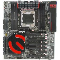
X79 Dark - Motherboard EVGA - Free user manual and instructions
Find the device manual for free X79 Dark EVGA in PDF.


| Product Type | Motherboard |
| Brand | EVGA |
| Model | X79 Dark |
| Form Factor | ATX |
| Chipset | Intel X79 Express |
| CPU Socket | LGA 2011 |
| Memory Type | DDR3 |
| Maximum Memory | 64GB (4x16GB) Quad-Channel |
| Memory Slots | 8 x 240-pin DIMM |
| Expansion Slots | 4 x PCIe 3.0 x16 (supports SLI/CrossFire) |
| Storage SATA | 6 x SATA 6Gb/s ports |
| USB Ports | 4 x USB 3.0 (rear), 8 x USB 2.0 (via headers) |
| Audio | 8-channel HD Audio (Realtek ALC889) |
| Ethernet | Dual Gigabit Ethernet (Intel + Realtek) |
| Power Connectors | 24-pin ATX, 8-pin CPU, 4-pin CPU |
| Dimensions | 12.0 x 9.6 in (305 x 244 mm) |
| Weight | 2.5 lbs (1.1 kg) |
| Special Features | Overclocking optimized, Dark PCB design, high-quality Nichicon capacitors, onboard power/reset buttons, debug LED |
| Cooling | Heatsink on chipset and VRM |
| BIOS | UEFI with dual BIOS support |
| Operating System Support | Windows 7, 8, 10 (64-bit) |
Frequently Asked Questions - X79 Dark EVGA
User questions about X79 Dark EVGA
0 question about this device. Answer the ones you know or ask your own.
Ask a new question about this device
Download the instructions for your Motherboard in PDF format for free! Find your manual X79 Dark - EVGA and take your electronic device back in hand. On this page are published all the documents necessary for the use of your device. X79 Dark by EVGA.
USER MANUAL X79 Dark EVGA
Before You Begin....4
Parts NOT in the Kit 5
Intentions of the Kit....5
Motherboard Specifications 7-8
Unpacking and Parts Descriptions....8
Equipment....9-10
Hardware Installation....10
Safety Instructions....10
Preparing the Motherboard....11
Installing the CPU....11
Installing the Cooling Device....12
Installing System Memory (DIMMs)....13
Installing the Motherboard....14
Installing the I/O Shield....14
Securing the Motherboard into a System Case....15
Connecting Cables....15
24pin ATX Power (PW1)....16
8pin ATX 12V Power....17
BIOS Select Switch (optional)....17
Connecting Internal Headers....18
Front Panel Header ....18
USB Headers 19
Audio 20
PCI-E x1 Slots....21
PCI-E x16/x8 Slots....21
Onboard Buttons 22
Clear CMOS Button....22
RESET and POWER Button....22
Post Port Debug LED and LED Status Indicators 23
Installing Drivers and Software....24
Windows 7/Vista/XP Driver Installation....24
POST Codes....27-31
EVGA Glossary of Terms 32-34
Compliance Information 33
Before You Begin...
The true next generation motherboards have arrived with the EVGA X79 motherboards! This product packs in the latest technologies to give you an uncompromised experience:
Uncompromised Performance – Unparalleled memory bandwidth with true quad channel DDR3 memory support, and Intel Turbo Boost Technology 2.0 gives you intelligent computing by optimizing performance on the fly! NVIDIA SLI® and PhysX give you the expansion you need to maximize your graphics performance.
Uncompromised Power – High performance PWM and POSCAP Capacitors deliver clean, optimal power to your system for maximum overclocking. Also, with built in EVGA EVBot support*, you can overclock on the fly from the palm of your hand.
Uncompromised Features – This board is loaded with the latest technologies like a full UEFI BIOS, USB 3.0 Ports, SATA III/6G support, PCI-E 3.0 ports, E-SATA, a true next generation board layout, and more!
*sold separately
Parts NOT in the Kit
This kit contains all the hardware necessary to install and connect your new EVGA X79 Dark Motherboard. However, it does not contain the following items that must be purchased separately to make the motherboard functional.
Intel Socket 2011 Processor
DDR3 System Memory
□ CPU Cooling Device
PCI Express Graphics Card
Power Supply
EVGA assumes you have purchased all the necessary parts needed to allow for proper system functionality. For a full list of supported CPUs on this motherboard, please visit www.evga.com/support/motherboard
Intentions of the Kit
This kit provides you with the motherboard and all connecting cables necessary to install the motherboard into a PC case.
When replacing a motherboard in a PC case, you will need to reinstall an operating system even though the current storage drive may already have one installed.
EVGA X79
Motherboard
Motherboard Specifications
Size
EATX form factor of 12 inches x 10.3 inches
□ Microprocessor support
Intel Socket 2011 Processor
□ Operating systems
Supports Windows 8 / 7 / Vista / XP
□ Contains Intel X79 chipset
□ System Memory support
Supports Quad channel DDR3-2400MHz+. Officially supports up to 64GB of DDR3 memory.
USB 2.0 Ports
Supports hot plug
Supports wake-up from S1 and S3 mode
Supports USB 2.0 protocol up to a 480 Mbps transmission rate
USB 3.0 Ports
Backwards compatible USB 2.0 and USB 1.1 support
Supports transfer speeds up to 5Gbps
SATA Ports
SATA ports up to 3G (300 MB/s) data transfer rate
SATA ports up to 6G (600 MB/s) data transfer rate
Support for RAID 0, RAID 1, RAID 0+1, RAID5 and RAID 10
ESATA
Onboard Intel LAN
Supports 10/100/1000 Mb/sec Ethernet
Supports teaming
Onboard Audio
Realtek ALC898 High-Definition audio
Supports 8-channel audio
Supports Jack-Sensing function
Supports Optical Output
PCI-E Support
PCI-E 2.0 Slots (PCI-E 3.0 Ready**)
Low power consumption and power management features
Power Functions
Supports ACPI (Advanced Configuration and Power Interface)
Supports S0 (normal), S1 (power on suspend), S3 (suspend to RAM), S4 (Suspend to disk - depends on OS), and S5 (soft - off)
□ Expansion Slots
PCI-E x4 slot
PCI-E x8/x16 slots
Unpacking and Parts Descriptions
Unpacking
The EVGA X79 Dark Motherboard comes with all the necessary cables for adding a motherboard to a system case. If replacing a motherboard, you may not need many of these cables.
Equipment
The following accessories are included with the EVGA X79 Dark Motherboard:

natural_image
Close-up of a computer motherboard with visible slots and a red logo (no readable text or symbols)The EVGA X79 Dark Motherboard
This PCI-E motherboard contains the Intel X79 chipset and is SLI® -ready.

Visual Guide
Helps to quickly and visually guide you through the hardware installation of the motherboard.
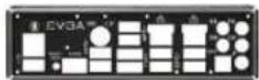
I/O Shield
Installs in the system case to block radio frequency transmissions, protect internal components from dust, foreign objects, and aids in proper airflow within the chassis.

natural_image
Three black and gold-colored cable connectors with connector pins, arranged diagonally (no text or symbols visible)2-Port SATA Power Cables
Allows a Molex power connector to adapt to a SATA power connector.
natural_image
Close-up of a black Ethernet cable connector with multiple ports (no text or symbols visible)
natural_image
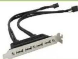
Close-up of a black USB cable with two blue ports and a gray connector (no text or symbols visible)4-Port USB 2.0 Bracket
Provides four additional USB ports to the back panel of the chassis.
2-Port USB 3.0 Bracket
Allows addition of 2 USB 3.0 ports by Connecting to the motherboard header.

SATA 3G/6G Data Cables
Used to support the SATA protocol and each one connects a single drive to the motherboard.

4-way SLI® Bridge
Bridges four graphics cards together which allows for 4-way SLI ^® .

3-way SLI® Bridge
Bridges three graphics cards together which allows for 3-way SLI ^® .

2-way SLI® Bridge
Bridges two graphics cards together which allows for 2-way SLI®.

Optional 1366 Backplate
Allows use of a socket 1366 cooler. This backplate is optional.
Installation CD
Contains drivers and software needed to setup the motherboard.

User Manual
The user manual you are reading right now!
Hardware Installation
This section will guide you through the installation of the motherboard. The topics covered in this section are:
□ Preparing the motherboard
□ Installing the CPU
☐ Installing the Cooling Device
□ Installing the memory
□ Installing the motherboard
Connecting cables
Safety Instructions
To reduce the risk of fire, electric shock, and injury, always follow basic safety precautions.
Remember to remove power from your computer by disconnecting the AC main source before removing or installing any equipment from/to the computer chassis.
Preparing the Motherboard
Installing the CPU
Be very careful when handling the CPU. Hold the processor only by the edges and do not touch the bottom of the processor.
Use the following procedure to install the CPU onto the motherboard:
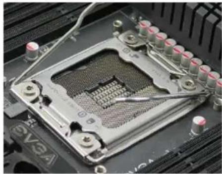
☐ Unhook the left socket lever by pushing down and away from the socket.
☐ Unhook the right socket lever by pushing down and away from the socket.
☐ Gently press the left socket lever and the load plate will lift from the socket.
Open the load plate and make sure not to damage any of the pins inside of the socket.
natural_image
Close-up of a computer motherboard showing the CPU socket and surrounding hardware (no visible text or symbols)
natural_image
Close-up of a computer processor with visible CPU socket and surrounding hardware (no text or symbols)Note: After removing the CPU socket cover, it is recommended to store it in case you ever need to transport your motherboard. If you ever remove the CPU, it is highly recommended to reinstall the socket cover.
EVGA X79 Dark Motherboard
☐ Align the notches on the CPU to the notches in the socket.
☐ Lower the processor straight down into the socket.
Note: Make sure the CPU is fully seated and level in the socket.
☐ Lower the load plate so it is resting on the CPU.
☐ Press the right socket lever down to lock into place.
☐ Carefully lock the lever back into place.

natural_image
Close-up of hands installing a CPU into a motherboard with visible slots and cooling fans (no text or symbols)
natural_image
Close-up of a hand pressing a CPU socket on a motherboard (no visible text or symbols)
natural_image
Close-up of a CPU socket on a motherboard with a finger inserted, no visible text or symbolsInstalling the Cooling Device
There are many different cooling devices that can be used with this motherboard. Follow the instructions that came with your cooling assembly.
Installing System Memory (DIMMs)
Your new motherboard has eight 240-pin slots for DDR3 memory. These slots support 2GB, 4GB and 8GB DDR3 DIMMs. There must be at least one memory slot populated to ensure normal operation.
The Intel X79 chipset supports quad channel memory; it is required to populate slots 1, 3, 5, 7 first. Board will not boot if slots 2,4,6,8 populated without 1,3,5,7.

natural_image
Close-up of a computer motherboard with visible CPU socket and cooling fins (no text or symbols)Use the following procedure to install DIMMs. Note that there is only one gap near the center of the DIMM slots. This slot matches the slot on the DIMM to ensure the component is installed properly.
☐ Unlock a DIMM slot by pressing the module clip outward.
☐ Align the memory module to the DIMM slot, and insert the module vertically into the DIMM slot. The plastic clips at top side of the DIMM slot automatically lock the DIMM into the connector.
Installing the Motherboard
The sequence of installing the motherboard into a system case depends on the chassis you are using and if you are replacing an existing motherboard or working with an empty system case. Determine if it would be easier to make all the connections prior to this step or to secure the motherboard and then make all the connections. It is normally easier to secure the motherboard first.
Use the following procedure to install the I/O shield and secure the motherboard into the chassis.
Note: Be sure that the CPU fan assembly has enough clearance for the system case covers to lock into place and for the expansion cards. Also make sure the CPU Fan assembly is aligned with the vents on the covers. This will depend on the system case being used.
Installing the I/O Shield/Cover
The motherboard kit comes with an I/O shield that is used to block radio frequency transmissions, protects internal components from dust and foreign objects, and promotes correct airflow within the chassis.
Before installing the motherboard, install the I/O shield from the inside of the chassis. Press the I/O shield into place and make sure it fits securely.
Also included is an I/O cover. This I/O cover adds a unique appearance to the I/O area of the motherboard and is completely optional. If you wish to use the cover, please place it over the I/O area, and install the chassis screws. The chassis screws are intended to hold the I/O cover down.
Securing the Motherboard into a System Case
Most system cases have a base with mounting studs or spacers to allow the motherboard to be secured to the chassis and help to prevent short circuits. If there are studs that do not align with a mounting hole on the motherboard, it is recommended that you remove that stud to prevent the possibility of a short circuit.
☐ Carefully place the motherboard onto the stand offs located inside the chassis.
☐ Align the mounting holes with the stand offs.
☐ Align the connectors to the I/O shield and/or I/O cover.
☐ Ensure that the fan assembly is aligned with the chassis vents according to the fan assembly instruction.
☐ Secure the motherboard with a recommended minimum of nine (9) screws.
Connecting Cables
This section takes you through all the necessary connections on the motherboard. This will include:
Power Connections
24pin ATX power (PW1)
8pin ATX 12V power
Internal Headers
Front Panel Header
USB Headers
Audio Header
SATA II
SATA III
USB 3.0/2.0
□ Expansion slots
□ CMOS Clear Button
24pin ATX Power (PW1)
PW1 is the main power supply connector located along the right edge of the board. Make sure that the power supply cable and pins are properly aligned with the connector on the motherboard. Firmly plug the power supply cable into the connector and make sure it is secure.
The 24pin Power Connector may be standard or right angled depending on your motherboard model.

natural_image
Close-up of a circuit board with a black rectangular component on top (no visible text or symbols)Right Angled 24pin Power Connector
| Connector | Pin | Signal | Pin | Signal |
 | 1 | +3.3V | 13 | +3.3V |
| 2 | +3.3V | 14 | -12V | |
| 3 | GND | 15 | GND | |
| 4 | +5V | 16 | PS_ON | |
| 5 | GND | 17 | GND | |
| 6 | +5V | 18 | GND | |
| 7 | GND | 19 | GND | |
| 8 | PWROK | 20 | RSVD | |
| 9 | +5V_AUX | 21 | +5V | |
| 10 | +12V | 22 | +5V | |
| 11 | +12V | 23 | +5V | |
| 12 | +3.3V | 24 | GND |
8-pin ATX 12V Power (PW12-1 & PW12-2)
PW12-1 & PW12-2, the 8-pin ATX 12V power connections, are used to provide power to the CPU. Align the pins to the connector and press firmly until seated. The secondary is optional for improved overclocking.

BIOS Select Switch
The BIOS Select Switch is located directly on the bottom edge of the motherboard. This jumper controls which of physical BIOS chips are to be used when the system is powered on.

Connecting Internal Headers
Front Panel Header
The front panel header on this motherboard is used to connect the following four cables.
PWRLED
Attach the front panel power LED cable to these two pins of the connector. The Power LED indicates the system's status. When the system is powered on, the LED will be on.

Note: Some system cases may not have all four cables. Be sure to match the name on the connectors to the corresponding pins.
PWRSW
Attach the power button cable from the case to these two pins. Pressing the power button on the front panel turns the system on and off rather than using the onboard button.
HD\_LED
Attach the hard disk drive indicator LED cable to these two pins. The HDD indicator LED indicates the activity status of the hard disks.
□ RESET
Attach the Reset switch cable from the front panel of the case to these two pins.
| Pin | Signal | |
| HD_LED | 1 | HD_PWR |
| 3 | HD Active | |
| PWRLED | 2 | PWR LED |
| 4 | STBY LED | |
| RESET | 5 | Ground |
| 7 | RST BTN | |
| PWRSW | 6 | PWR BTN |
| 8 | Ground | |
| No Connect | 9 | +5V |
| Empty | 10 | Empty |
USB Headers
This motherboard contains USB 3.0 and 2.0 ports that are exposed on the rear panel of the chassis. The motherboard also contains 10-pin internal header connectors onboard that can be used to connect an optional external bracket containing up to four (4) USB 2.0 ports. It may also have an internal header connector for USB 3.0.

natural_image
Close-up of two electronic component blocks labeled USB 3/4 and USB 0/1, with red connectors (no readable text or symbols beyond labels)☐ Secure the bracket to either the front or rear panel of your chassis (not all chassis are equipped with the front panel option).
☐ Connect the two ends of the cables to the USB 2.0 or 3.0 headers on the motherboard.
| Connector | Pin | Signal |
USB 2.0 Header Connector 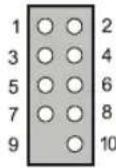 | 1 | 5V_DUAL |
| 3 | D- | |
| 5 | D+ | |
| 7 | GND | |
| 9 | Empty | |
| Pin | Signal | |
| 2 | 5V_DUAL | |
| 4 | D- | |
| 6 | D+ | |
| 8 | GND | |
| 10 | No Connect |
Audio
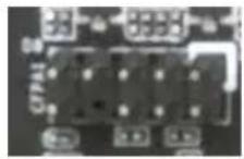
The audio connector supports HD audio standard and provides two kinds of audio output choices: the Front Audio and the Rear Audio.
| Connector | Pin | Signal |
| Front Audio Connector10 98 76 54 32 1 | 1 | PORT1_L |
| 2 | AUD_GND | |
| 3 | PORT1_R | |
| 4 | PRECENCE_J | |
| 5 | PORT2_R | |
| 6 | SENSE1_RETURN | |
| 7 | SENSE_SEND | |
| 8 | Empty | |
| 9 | PORT2_L | |
| 10 | SENSE2_RETURN |
PCI-E x4 Slot
There are PCI-E x4 slots that are designed to accommodate less bandwidth-intensive cards, such as a sound or network card.
PCI-E x16/x8 Slots
These PCI-E slots are reserved for Graphics Cards and PCI-E x1, x4, x8 and x16 devices. The design of this motherboard supports multiple Graphics Card technologies such as SLI® or CrossFire.
When installing a PCI-E Graphics Card, be sure the retention clip snaps and locks the card into place. If the card is not seated properly, it could cause a short across the pins. Secure the card's metal bracket to the chassis back panel with the screw used to hold the blank cover.
PCI-E Lane Distribution
☐ PE1 - x16 (x8 if PE2 used)
PE2-x8
☐ PE3 – x16 (x8 if PE4 used)
PE4-x8
PE5-x4
☐ PE6 - x8 (x4 if PE5 used)
Onboard Buttons
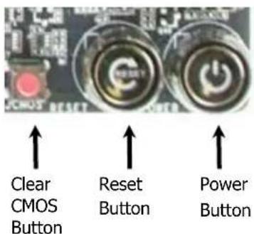
These onboard buttons include RESET, POWER and Clear CMOS. These functions allow you to easily reset the system, turn on/off the system, or clear the CMOS.
Clear CMOS Button
The motherboard uses the CMOS RAM to store all the set parameters. The CMOS can be cleared by pressing the Clear CMOS button either onboard or on the external I/O Panel.

RESET and POWER Button
These onboard buttons allow you to easily turn on/off the system. These buttons allow for easy debugging and testing of the system during troubleshooting situations.
The POWER button with an integrated LED indicates the system's status. When the system is powered on, the LED remains a solid red.
The RESET button with an integrated LED indicates the activity status of the hard disk drives and will flicker accordingly.
Post Port Debug LED and LED Status Indicators
Post Port Debug LED
Provides two-digit POST codes to show why the system may be failing to boot. It is useful during troubleshooting situations. This Debug LED will also display current CPU socket temperatures after the system has fully booted into the Operating System.

Debug LED with CPU Temperature Monitor
LED Status Indicators
Theses LEDs indicate the system's status and are located near the 24pin connector.
POWER LED:
When the System is powered on: This LED is on.
DIMM LED:
When the Memory slot is functional: This LED is on.
STANDBY LED:
When the System is in Standby Mode: This LED is on. This LED will remain on as long as the motherboard is receiving constant power.
Installing Drivers and Software
Note: It is important to remember that before installing the driver CD that is shipped in the kit, you need to load your operating system. The motherboard supports 32bit and 64bit versions of Windows 8, 7, Vista and XP.
The kit comes with a CD that contains utilities, drivers, and additional software.
The CD that has been shipped with the EVGA X79 Motherboard contains the following software and drivers:
Chipset Drivers
□ Audio Drivers
RAID Drivers
LAN Drivers
USB 3.0 Drivers
□ EVGA E-LEET
□ User's Manual
Windows 8/7/Vista/XP Driver Installation
- Insert the EVGA X79 installation CD for the motherboard included in the kit.
- The CD will autorun. Install the drivers and utilities listed on the install screen. If the CD does not run, go to My Computer and click on the CD to open.
POST Codes
This section provides the AMI POST Codes for the EVGA X79 Dark Motherboard during system boot up.
The POST Codes are displayed on the Debug LED readout located directly onboard the motherboard.
This Debug LED will also display current CPU temperatures after the system has fully booted into the Operating System.
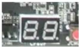
Debug LED with CPU Temperature Monitor
AMI POST Codes
| 01 | Power on. Reset type detection (soft/hard). |
| 02 | AP initialization before microcode loading |
| 03 | North Bridge initialization before microcode loading |
| 04 | South Bridge initialization before microcode loading |
| 05 | OEM initialization before microcode loading |
| 06 | Microcode loading |
| 07 | AP initialization after microcode loading |
| 08 | North Bridge initialization after microcode loading |
| 09 | South Bridge initialization after microcode loading |
| 0A | OEM initialization after microcode loading |
| 0B | Cache initialization |
| 0C-0D | Reserved for future AMI SEC error codes |
| 0E | Microcode not found |
| 0F | Microcode not loaded |
| 10 | PEI Core is started |
| 11-14 | Pre-memory CPU initialization is started |
| 15-18 | Pre-memory North Bridge initialization is started |
| 19-1C | Pre-memory South Bridge initialization is started |
| 1D-2A | OEM pre-memory initialization codes |
| 2B | Memory initialization. Serial Presence Detect (SPD) |
| data reading | |
| 2C | Memory initialization. Memory presence detection |
| 2D | Memory initialization. Programming memory timing information |
| 2E | Memory initialization. Configuring memory |
| 2F | Memory initialization (other). |
| 30 | Reserved for ASL (see ASL Status Codes section below) |
| 31 | Memory Installed |
| 32 | CPU post-memory initialization is started |
| 33 | CPU post-memory initialization. Cache initialization |
| 34 | CPU post-memory initialization. Application Processor(s) (AP) initialization |
| 35 | CPU post-memory initialization. Boot Strap Processor (BSP) selection |
| 36 | CPU post-memory initialization. System Management Mode (SMM) initialization |
| 37-3A | Post-Memory North Bridge initialization is started |
| 3B-3E | Post-Memory South Bridge initialization is started |
| 3F-4E | OEM post memory initialization codes |
| 4F | DXE IPL is started |
| 50 | Memory initialization error. Invalid memory type or incompatible memory speed |
| 51 | Memory initialization error. SPD reading has failed |
| 52 | Memory initialization error. Invalid memory size or memory modules do not match. |
| 53 | Memory initialization error. No usable memory detected |
| 54 | Unspecified memory initialization error. |
| 55 | Memory not installed |
| 56 | Invalid CPU type or Speed |
| 57 | CPU mismatch |
| 58 | CPU self test failed or possible CPU cache error |
| 59 | CPU micro-code is not found or micro-code update is failed |
| 5A | Internal CPU error |
| 5B | reset PPI is not available |
| 5C-5F | Reserved for future AMI error codes |
| E0 | S3 Resume is stared (S3 Resume PPI is called by the DXE IPL) |
| E1 | S3 Boot Script execution |
| E2 | Video repost |
| E3 | OS S3 wake vector call |
| E4-E7 | Reserved for future AMI progress codes |
| E8-EB | S3 Resume Failed |
| EC-EF | Reserved for future AMI error codes |
| F0 | Recovery condition triggered by firmware (Auto recovery) |
| F1 | Recovery condition triggered by user (Forced recovery) |
| F2 | Recovery process started |
| F3 | Recovery firmware image is found |
| F4 | Recovery firmware image is loaded |
| F5-F7 | Reserved for future AMI progress codes |
| F8 | Recovery PPI is not available |
| F9 | Recovery capsule is not found |
| FA | Invalid recovery capsule |
| FB-FF | Reserved for future AMI error codes |
| 60 | DXE Core is started |
| 61 | NVRAM initialization |
| 62 | Installation of the South Bridge Runtime Services |
| 63-67 | CPU DXE initialization is started |
| 68 | PCI host bridge initialization |
| 69 | North Bridge DXE initialization is started |
| 6A | North Bridge DXE SMM initialization is started |
| 6B-6F | North Bridge DXE initialization (North Bridge module specific) |
| 70 | South Bridge DXE initialization is started |
| 71 | South Bridge DXE SMM initialization is started |
| 72 | South Bridge devices initialization |
| 73-77 | South Bridge DXE Initialization (South Bridge module specific) |
| 78 | ACPI module initialization |
| 79 | CSM initialization |
| 7A-7F | Reserved for future AMI DXE codes |
| 80-8F | OEM DXE initialization codes |
| 90 | Boot Device Selection (BDS) phase is started |
| 91 | Driver connecting is started |
| 92 | PCI Bus initialization is started |
| 93 | PCI Bus Hot Plug Controller Initialization |
| 94 | PCI Bus Enumeration |
| 95 | PCI Bus Request Resources |
| 96 | PCI Bus Assign Resources |
| 97 | Console Output devices connect |
| 98 | Console input devices connect |
| 99 | Super IO Initialization |
| 9A | USB initialization is started |
| 9B | USB Reset |
| 9C | USB Detect |
| 9D | USB Enable |
| 9E-9F | Reserved for future AMI codes |
| A0 | IDE initialization is started |
| A1 | IDE Reset |
| A2 | IDE Detect |
| A3 | IDE Enable |
| A4 | SCSI initialization is started |
| A5 | SCSI Reset |
| A6 | SCSI Detect |
| A7 | SCSI Enable |
| A8 | Setup Verifying Password |
| A9 | Start of Setup |
| AA | Reserved for ASL (see ASL Status Codes section below) |
| AB | Setup Input Wait |
| AC | Reserved for ASL (see ASL Status Codes section below) |
| AD | Ready To Boot event |
| AE | Legacy Boot event |
| AF | Exit Boot Services event |
| B0 | CPU Memory controller configuration |
| B1 | Runtime Set Virtual Address MAP End |
| B2 | iMC init |
| B3 | Memory training |
| B4 | Memory training |
| B5 | Memory training / timing training |
| B6 | Memory training |
| B7 | Memory training |
| B8-BF | Memory training / DRAM final configuration |
| C0-CF | OEM BDS initialization codes |
| D0 | CPU initialization error |
| D1 | North Bridge initialization error |
| D2 | South Bridge initialization error |
| D3 | Some of the Architectural Protocols are not available |
| D4 | PCI resource allocation error. Out of Resources |
| D5 | No Space for Legacy Option ROM |
| D6 | No Console Output Devices are found |
| D7 | No Console Input Devices are found |
| D8 | Invalid password |
| D9 | Error loading Boot Option (LoadImage returned error) |
| DA | Boot Option is failed (StartImage returned error) |
EVGA Glossary of Terms
AC – Alternating Current
ACPI - Advanced Configuration and Power Interface
AFR – Alternate Frame Rendering
APIC - Advanced Programmable Interrupt Controller
ACPI – Advanced Configuration and Power Interface
BCLK – Base Clock (or operating frequency of base system bus)
BIOS - Basic Input Output System
CD-ROM - Compact Disc Read-Only Memory
CMOS - Complementary Metal-Oxide Semiconductor
CPU – Central Processing Unit
EVGA X79 Dark Motherboard
DDR - Double Data Rate 2
DIMM - Dual In-line Memory Module
DMI – Direct Memory Interface
DRAM - Dynamic random access memory
DVD - Digital Versatile Disc
DVI – Digital Video Interface
FDC - Floppy Disk Controller
FSB – Front Side Bus
FTW – For the Win!
GHz – Gigahertz
GPU – Graphics Processing Unit
HDD - Hard Disk Drive
HDMI - High-Definition Multimedia Interface
HDR – High Dynamic Range Lighting
HPET - High Precision Event Timer
HT – Hyper-Threading
HSF - Heat Sink Fan
I/O - Input/ Output
IDE - Integrated Drive Electronics
IEEE - Institute of Electrical and Electronics Engineers
IGP - Integrated Graphics Processors
IMC – Integrated memory controller
IRQ - Interrupt Request
JBOD - Just a Bunch of Disks
JEDEC - Joint Electron Device Engineering Council
LAN - Local Area Network
LCD - Liquid Crystal Display
LGA – Land Grid Array
LN2 – Liquid Nitrogen Cooling
MAC - Media Access Control
MCP - Media and Communications Processor
Intel ME – Intel Management Engine
MHz – Megahertz
NCQ - Native Command Queuing
NIC - Network Interface Card
NTFS - New Technology File System
OEM - Original Equipment Manufacturer
PATA - Parallel Advanced Technology Attachment
PCB - Printed Circuit Board
PCH – Platform Controller Hub
PCI - Peripheral Component Interconnect
PCI-E - Peripheral Component Interconnect Express
PCI-X - Peripheral Component Interconnect Extended
PLL – Phase Locked Loop
POST – Power on Self Test
PWM – Pulse Width Modulation
QDR - Quad Data Rate
QPI – Quick Path Interconnect
RAID - Redundant Array of Inexpensive Disks
RAM – Random Access Memory
ROM – Read Only Memory
RGB - Red Green Blue
SATA - Serial Advanced Technology Attachment
SAS – Serial Attached SCSI
SB - Southbridge
SCSI - Small Computer System Interface
SFR – Split Frame Rendering
EVGA X79 Dark Motherboard
SLI - Scalable Link Interface
SPD - Serial Presence Detect
SPDIF - Sony/Philips Digital Interconnect Format
SPP - System Platform Processors
SSD – Solid State Drive
TCP/IP - Transmission Control Protocol/Internet Protocol
USB - Universal Serial Bus
VDroop - VCore Voltage Drop
VGA - Video Graphics Array
VREG – Voltage Regulator
1337 – This is reserved for the EVGA Elite!
Compliance Information
FCC Compliance Information
This device complies with FCC Rules Part 15. Operation is subject to the following two conditions: (1) This device may not cause harmful interference, and (2) this device must accept any interference received, including interference that may cause undesired operation. This equipment has been tested and found to comply with the limits for a Class B digital device, pursuant to Part 15 of the FCC Rules. These limits are designed to provide reasonable protection against harmful interference in a residential installation. This equipment generates, uses and can radiate radio frequency energy and, if not installed and used in accordance with the manufacturer's instructions, may cause harmful interference to radio communications. However, there is no guarantee that interference will not occur in a particular installation. If this equipment does cause harmful interference to radio or television reception, which can be determined by turning the equipment off and on, the user is encouraged to try to correct the interference by one or more of the following measures: (1) Increase the separation between the equipment and signal source, or (2) connect the equipment to an outlet on a circuit different from that to which the signal source is connected. Consult the dealer or an experienced computer technician for help. The use of shielded cables for connection of peripheral devices to the PC systems is required to ensure compliance with FCC regulations. Changes or modifications to this unit not expressly approved by the party responsible for compliance could void the user's authority to operate the equipment.
CE Compliance Information
Generic Radiation Interference Standard for Information Technology Equipment. (EN 55022: 2006, Class B), (EN 61000-3-2: 2006), (EN 61000-3-3: 1995 + A1: 2001 + A2: 2005). Warning: This is a Class B product. In a domestic environment this product may cause radio interference in which case the user may be required to take adequate measure. Generic Immunity Standard for Information Technology Equipment. (EN 55024: 1998 + A1: 2001 + A2: 2003).
Trademark & Copyright Information
2001-2013 EVGA Corp. EVGA, the EVGA logo and combinations thereof are trademarks of EVGA Corp. All brand names, company names, service marks, logos, and trademarks of the company, or its affiliates or licensors are trademarks or registered trademarks of the company or its subsidiaries, affiliates or licensors in the US and other countries. Other company, products and service names may be trademarks or service marks of others. EVGA reserves the right to terminate this license if there is a violation of its terms or default by the Original Purchaser. Upon termination, for any reason, all copies of Software and materials must be immediately returned to EVGA and the Original Purchaser shall be liable to EVGA.com CORP for any and all damages suffered as a result of the violation or default.
Legal Information
All material including but not limited to, text, data, design specifications, diagnostics, graphics, logos, reference boards, files, images, drawings, and software including this document and the software itself (together and separately) is owned, controlled by, licensed to, or used with permission by Company and is protected by copyright, trademark, and other intellectual property rights. All is being provided "as is", EVGA Corporation makes no warranties, whether express or implied, statutory or otherwise with respect to the materials and expressly disclaims all implied warranties of non-infringement, merchantability, and fitness for a particular purpose. In no event shall the liability of EVGA Corporation for claims arising from the use of the materials by anyone exceed the original purchase price of the materials (or replacement of the materials at EVGA Corporation's option). All information furnished is believed to be accurate and reliable. However, EVGA Corporation assumes no responsibility for the consequences of use of such information or for any infringement of patents or other rights of third parties that may result from its use, or use of the Software. No license is granted by implication or otherwise under any patent or patent rights of EVGA Corporation except as expressly provided herein. All specifications mentioned in this publication are subject to change without notice.
Ver. 2


- Before You Begin...
- Parts NOT in the Kit
- Intentions of the Kit
- EVGA X79
- Motherboard
- Motherboard Specifications
- Unpacking and Parts Descriptions
- Unpacking
- Equipment
- The EVGA X79 Dark Motherboard
- Visual Guide
- I/O Shield
- 2-Port SATA Power Cables
- 4-Port USB 2.0 Bracket
- 2-Port USB 3.0 Bracket
- SATA 3G/6G Data Cables
- 4-way SLI® Bridge
- 3-way SLI® Bridge
- 2-way SLI® Bridge
- Optional 1366 Backplate
- Installation CD
- User Manual
- Hardware Installation
- Safety Instructions
- Preparing the Motherboard
- Installing the CPU
- EVGA X79 Dark Motherboard
- Installing the Cooling Device
- Installing System Memory (DIMMs)
- Installing the Motherboard
- Installing the I/O Shield/Cover
- Securing the Motherboard into a System Case
- Connecting Cables
- 24pin ATX Power (PW1)
- 8-pin ATX 12V Power (PW12-1 & PW12-2)
- BIOS Select Switch
- Connecting Internal Headers
- Front Panel Header
- PWRLED
- PWRSW
- HD\_LED
- □ RESET
- USB Headers
- Audio
- PCI-E x4 Slot
- PCI-E x16/x8 Slots
- PCI-E Lane Distribution
- Onboard Buttons
- Clear CMOS Button
- RESET and POWER Button
- Post Port Debug LED and LED Status Indicators
- Post Port Debug LED
- LED Status Indicators
- Installing Drivers and Software
- Windows 8/7/Vista/XP Driver Installation
- POST Codes
- EVGA Glossary of Terms
- Compliance Information
- FCC Compliance Information
- CE Compliance Information
- Trademark & Copyright Information
- Legal Information
Brand : EVGA
Model : X79 Dark
Category : Motherboard