
IPV58 - Surveillance Camera EBODE - Free user manual and instructions
Find the device manual for free IPV58 EBODE in PDF.


| Product Type | IP Surveillance Camera |
| Brand | ebode |
| Model | IPV58 |
| Dimensions (approx.) | 120 x 70 x 70 mm |
| Weight (approx.) | 350 g |
| Power Supply | DC 12V, 1A (adapter included) |
| Power Consumption | 5W (max) |
| Image Sensor | 1/2.7" CMOS, 2 Megapixel |
| Resolution | 1920 x 1080p (Full HD) |
| Night Vision | Up to 30m with IR LEDs |
| Lens | 3.6mm fixed lens, F2.0 |
| Field of View | 78° horizontal |
| Video Compression | H.265 / H.264 |
| Connectivity | Wi-Fi 802.11 b/g/n, 2.4 GHz |
| Audio | Built-in microphone and speaker |
| Storage | MicroSD card up to 128 GB, Cloud storage |
| Motion Detection | Yes, with push notifications |
| Two-Way Audio | Yes |
| Weather Resistance | IP65 (outdoor suitable) |
| Mounting Bracket | Included, wall or ceiling mount |
| Operating Temperature | -20°C to 50°C |
| Compatibility | iOS & Android app, ONVIF |
| Maintenance | Clean lens with soft dry cloth; keep vents clear |
| Safety | Use provided power adapter; do not expose to extreme heat |
| Spare Parts | Power adapter, mounting kit, screws |
| Repairability | Contact ebode support or authorized service center |
Frequently Asked Questions - IPV58 EBODE
User questions about IPV58 EBODE
0 question about this device. Answer the ones you know or ask your own.
Ask a new question about this device
Download the instructions for your Surveillance Camera in PDF format for free! Find your manual IPV58 - EBODE and take your electronic device back in hand. On this page are published all the documents necessary for the use of your device. IPV58 by EBODE.
USER MANUAL IPV58 EBODE
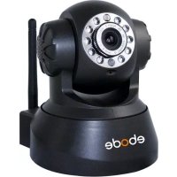
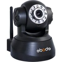
Outdoor IP Camera with Night Vision IP Vision 58
User Manual
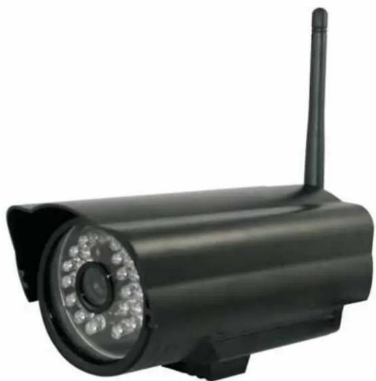
natural_image
Black surveillance camera with a mounted antenna and circular lens (no text or symbols visible)Index
1.0 INTRODUCTION
1.1 Features
1.2 Packing List
1.3 Product Views, Connections and Buttons
1.4 PC System Requirements
1.5 Hardware Installation
1.6 Software Installation
2.0 Software Operation
2.1 IP Camera Tool
2.1.1.1 Basic Properties
2.1.1.2 Network Configuration
2.1.1.3 Upgrade Firmware
2.1.1.4 Refresh Camera List
2.1.1.5 Flush Arp Buffer
2.1.1.6 About IP Camera Tool
2.2 Camera Login
2.3 For IE Browser
2.4 For Safari, Firefox, Google Browser
2.5 For Mobile Phone
2.6 ActiveX Mode (For IE Browser)
2.7 For Visitor
2.8 For Operator
2.9 For Administrator
3.0 SETTINGS AS ADMINISTRATOR
3.1 Multi-Device Settings
3.1.1 Set Multi-Device in LAN
3.1.2 Set Multi-Device for WAN
3.1.3 Upgrade Device Firmware
3.4 Wireless LAN Settings
3.5 ADSL Settings
3.6 UPnP Settings
3.7.1 To change the camera's port
3.7.2 DDNS Status
3.7.3 Set Port Forwarding in the router
3.8 System Settings
3.8.1 Device Info
3.9 Alias Settings
3.10 Date & Time Settings
3.11 Users Settings
3.12 Backup & Restore
3.13 Other Settings
3.14 Mail Service Settings
3.15 FTP Service Settings
3.16 Alarm Service Settings
3.16.1 Motion Detect Armed
3.16.2 Motion Detect Sensitivity
3.16.3 Alarm Input Armed / IO Linkage on Alarm
3.17 Send e-mail on Alarm
3.18 Path Settings
3.19 Server Push Mode (For Safari, Firefox, Google Browser)
3.20 Sign in mobile phone
4.0 APPENDIX
4.1 Frequently Asked Questions
4.2 Default Parameters
5.0 SPECIFICATIONS
6.0 OBTAINING TECHNICAL SUPPORT
1 WELCOME
This is an integrated wireless IP Camera solution. It combines a high quality digital Video Camera with network connectivity and a powerful web server to bring clear to your Desktop from anywhere on your local network or over the Internet.
The basic function of it is transmitting remote video on IP network. The high quality video image can be transmitted with 30fps speed on the LAN/WAN by using MJPEG hardware compression technology.
It is based on TCP/IP standard, build-in WEB server which could support Internet Explore. Therefore the management and maintenance of your device become more simply by using network to achieve the remote configuration, start-up and upgrade firmware.
You can use this IP Camera to monitor some special places such as your home and your office. Also controlling and managing images are simple by clicking the website through the network.
1.1 Features
☆Powerful high-speed video protocol processor
☆High-sensitivity 1/4" CMOS sensor
☆Picture total 300k pixels
☆Optimized MJPEG video compression for transmission
☆Multi-level users' management and passwords definition
☆Embedded Web Server for users to visit by IE
☆Support wireless network (WI-FI/802.11/b/g)
☆Supporting Dynamic IP (DDNS) and UPNP LAN and Internet (ADSL, Cable Modem)
☆Giving alarm in cause of motion detection
☆Supporting image snapshot
☆Support multiple protocols : HTTP/TCP/IP/UDP/SMTP/DDNS/SNTP/DHCP/FTP
☆Support WEP/WPA/WPA2 encryption
☆Support 3G phone, Smart phone control and surveillance
☆Support Firefox, Safari, Google chrome browser.
1.2 Packing List
Untie the pack and check the items contained against the following list:
• IP Camera X1
- Quick Start Guide X1
- Power Supply X1
- CD X1
• Network Cable X1
- Mounting bracket X1
NOTE: Please contact us immediately in case of any damaged or short of contents.
1.3 Product Views
1.3.1 Front View

Figure 1.1
Sensitive Hole: For light sensitive
Infrared LED: For night Vision.
LENS: CMOS sensor with fixed focus lens. (Default is 6mm, 3.6mm optional)
Antenna: WI-FI Antenna
Shell: For protection and waterproof
1.3.2 Rear Panel

Figure 1.2
Network Indicator LED: The green LED will on when connect to the network, the yellow LED will blink when data transferred
RJ45 Port: RJ-45/10-100 base T, connect the network cable here.
Power Jack: DC 5V/2A power supply
RESET BUTTON: Press and hold the RESET BUTTON for 15 Seconds, then the IPCAM will be reset back to the factory default Parameter. (Please keep the power on when do RESET)
1.3.3 Bottom View

natural_image
Close-up of an electric motor with labeled ports (QC PASSED) and a cable, no readable text or symbols beyond labels.Figure 1.3
Original ebode IPCAM have some stickers at the bottom/back, such as MAC address sticker, QC sticker etc. If your camera does not have these stickers, it may be a clone one, clone ebode IPCAM could not use the original firmware and obtain our good after sale service.
1.4 PC System Requirements
System configuration requirements : (Example for viewing four IPCAM)
CPU: 2.06GHz or above
Memory: 256M or above
Network Card: 10M or above
Display Card: 64M or above memory
Recommendable Operating system: Windows 2000/ XP/ Vista/ 7
1.5 Hardware Instruction
Follow the steps below to set up your camera hardware. Make sure to follow each step carefully to ensure that the camera operates properly
-
Install the Wi-Fi antenna
-
Plug the power adaptor into camera
-
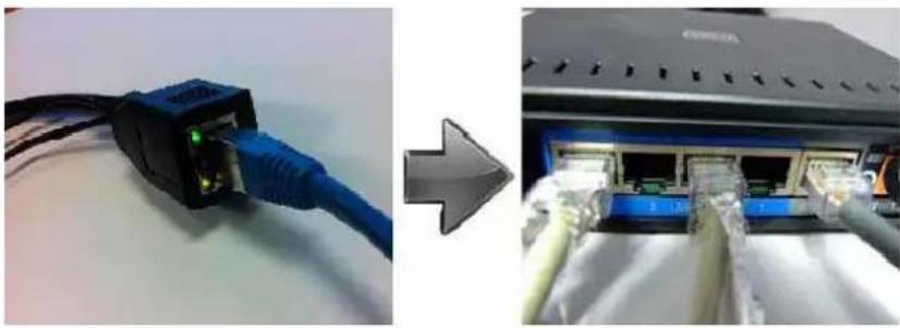
Plug the network cable into camera and router/switch
-
It takes approx 30 seconds to boot up the camera, then you will find the IP address from "IP Camera Tool" (Figure: 1.9)
-
When the power on and network cable connected, the green led of the real panel will keep on, The yellow led will keep flash, and the Indicator led at the front of the camera will flash. (The indicator LED can be controlled by software)
natural_image
Two-panel image showing a blue USB connector connected to a network device with illuminated ports (no visible text or symbols)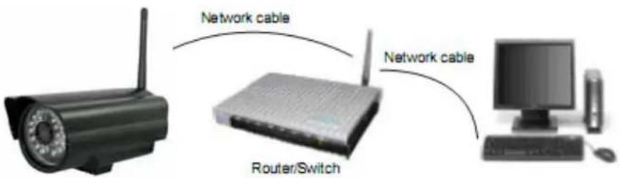
Figure 1.4
1.6 Software Installation
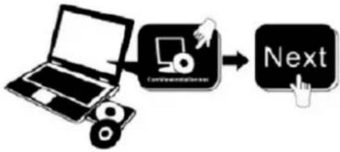
- IP Camera Tool: Insert the CD, a popup menu might appear like shown in the picture below.
- Select "Open Map" and click "OK"

- Open the "ebode IP Vision Software" map and double click "IPCamSetup.exe" then click next to complete the software installation. (Please note that on some computer systems it might take a few seconds before the "IPCamSetup" icon will appear)

In order to run smooth we will need to install the "ActiveX App" on each system we would like to use to visit the camera. The "AppInstall" file is located in the same folder as the "IPCamSetup" file from the previous steps. Please take the following steps:
- ActiveX: Double click "Appinstall.exe"—"Next"—"Install"—"Finish".
flowchart
graph LR
    A["Laptop"] --> B["Computer with monitor icon"]
    B --> C["Next Button"]
Figure 1.5
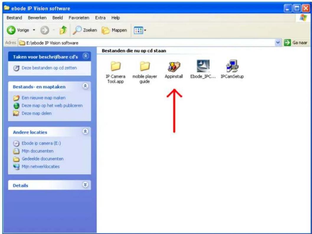
Figure 1.6

Figure 1.7

Figure 1.8
After this done, the icon "IP Camera Tool" IP Camera Tool will be displayed on desktop automatically.
CAUTION: Before installing and using the product, please read the following precautions carefully and make sure they are fully understood.
Use only the power adaptor attached with the product. Use unauthorized power adapter may cause damage to your IP Camera.
IP Camera terminal could be installed in an outdoor environment.
Do not touch the lens of the IP Camera at will. The optimum focus range has been set before it is delivered out of the factory. If you turn the lens, it may cause incorrect focus and vague images.
For firmware upgrading or connection with an external, refer to detailed instructions contained in the CD.
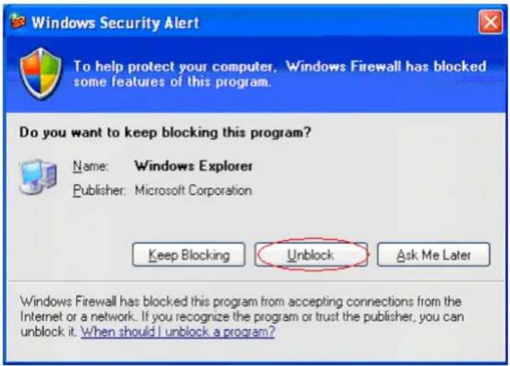
WARNING : On the first run of the program "IP Camera Tool" you might get a Windows Security Alert Popup. It will ask you to choose a setting for the firewall. Please make sure you choose the 'UNBLOCK' option. Your IP camera will not work without unblocking the firewall settings.
2. SOFTWARE OPERATION
2.1 IP Camera Tool
When the Device has been mounted properly, you can double click the Icon "IP Camera Tool"

and a dialog box as Figure 1.9 will pop up.

Figure 1.9
NOTE: The software searches IP Servers automatically over LAN.
There are 3 cases:
- No IP Cameras found within LAN. After about 1 minute search, the Result Field will show "not found IP Server" and the program shut automatically.
Manual version 1 - March 2012 11 IP Vision 58
- IP Cameras have been installed within LAN. All the IP Cameras will be listed and the total number is displayed in the result field as shown in Figure 1.9
- The IP Cameras installed within LAN do not share the same subnet with the monitoring PC. A prompt as shown in result field (prompt: Subnet doesn't match, double click to change!). Click the left mouse button to choose the prompt and click the right mouse, choose Network Configuration to set the static IP address of the Camera to the same subnet as LAN. (Figure 2.3)
NOTE: If it shows" Subnet doesn't match, double click to change!", you can also choose "Obtain IP from DHCP Server" to get a dynamic IP. (Figure 2.2) If the camera still doesn't show in the IP Camera Tool please use the Reset button on the bottom of the camera and hold it for 15 seconds with the power on. (Figure 1.3)
Please be sure your computer is on the same network as the camera!
2.1.1 Six Options
Choose the IP Camera and Click the right mouse button on that camera, there are six options: (Figure 2.0). Basic Properties, Network Configuration, Upgrade Firmware, Refresh Camera List, Flush Arp Buffer, About IP Camera Tool.
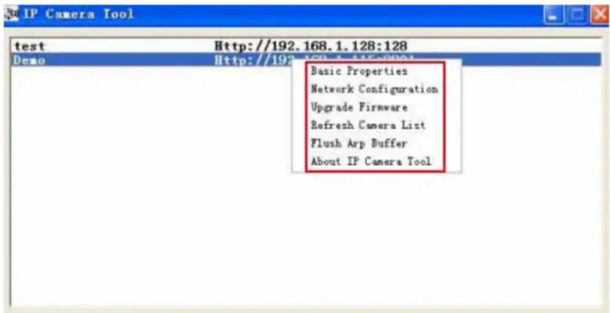
Figure2.0
2.1.1 .1 Basic Properties
There are some device information in the Basic Properties, such as Device ID, System Firmware Version, Web UI Version. (Figure 2.1)
The Device ID just is the camera's MAC ID, which should be the same as showed on the sticker at the bottom of camera. Every camera has its unique MAC ID. So if there are many IP address showed in the list, check the MAC ID, you can ensure which camera is it.
Sometimes, if there is no IP address showed on the IP Camera tool, maybe it's blocked by firewall, then add the MAC ID to the router, and give it a fixed IP or add the MAC ID as a trusted site. There are two MAC Address, one is Device MAC ID, the other is WIFI MAC ID.
WIFI MAC ID, you can find it from the sticker at the bottom of the camera, if this sticker lost, you can login your WIFI router, check the host status, which will show all the WIFI device connect to this router, you can also find the IPCAM's WIFI MAC ID there.

Figure2.1
2.1.1.2 Network Configuration
In this page, you can configure the Network parameter.

Figure2.2
Obtain IP from DHCP server: If clicked, the device will obtain IP from DHCP server. In other words, the camera will have a dynamic IP. (Make sure the Router which the camera connects has DHCP function and DHCP is enabled). (Figure 2.2)

Figure 2.3
IP address: Fill in the IP address assigned and make sure it is in the same subnet as the Gateway, and the subnet should be the same as your computer or router. (I.e. the first three sections are the same)
Subnet Mask: The default subnet mask of the equipment is: 255.255.255.0. You can find the subnet mask from your PC or router.
Gateway: Make sure it is in the same subnet with PC's IP address. Here gateway is the LAN IP of your router.
DNS Server: IP address of IPS network provider. You can also set it's the same as the Gateway.
NOTE: You can find the Subnet Mask, Gateway, DNS Server from your router, or check the local connection status of your computer, get all the parameters. Normally two DNS servers are optional.
Http Port: LAN port assigned for the equipment, default is 80. You could set another port number like 81, 801, 8001 etc.
User: Default administrator username is: admin (please make sure all are lowercase letter)
Password: Default password is bank, no password.
NOTE: When prompt "subnet doesn't match, double chick to change!" appeared, please set the IP Address, Subnet Mask, Gateway, DNS Server once again, or enable Obtain IP from DHCP server.
2.1.1.3 Upgrade Firmware
Enter the correct User and Password to upgrade system Firmware and Web UI. If you upgrade the camera, Please upgrade system firmware first and then upgrade Web UI. Or it may damage the camera. (Figure 2.4)
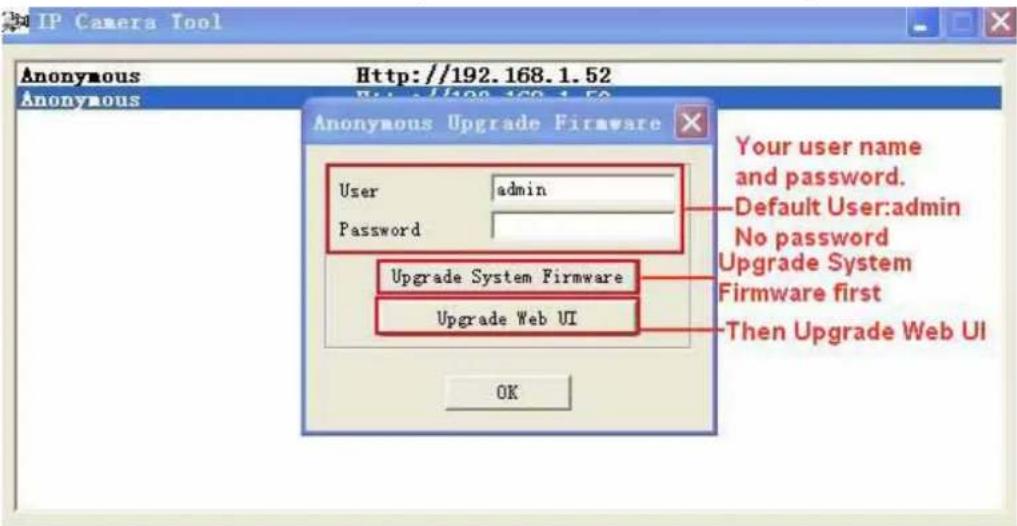
Figure 2.4
Please download the firmware package under the correct type of your camera before upgrade. Follow the upgrade document in the package carefully to upgrade. Please look readme firstly before you do upgrade.
CAUTION: You should not upgrade the firmware unnecessarily. It is possible to damage the camera if a mistake is made during the upgrade. If your camera works well with the current firmware, we recommend that you don't upgrade it.
NOTE: When doing an upgrade, remember you must keep the power on, and it's best to use wired mode, connected via the network cable.
2.1.1.4 Refresh Camera List
Refresh camera list manually.
2.1.1.5 Flush Arp Buffer
When cable network and wireless network of the device are fixed IP address .There is a problem you may encounter is can search the camera IP but can't open the camera web page .you may try to use Flush Arp Buffer.
2.1.1.6 About IP Camera Tool
Check the IP Camera Tool Version and IP Camera ActiveX Control Version here.
2.2 Camera Login
You can access the camera through IP Camera Tool or IE, Firefox, Safari, Google Chrome or other standard browser directly.
- Double click the IP address of the IP Camera listed (Figure 1.9). Select your language and browser you use. Note that IE Browser stands for "Internet Explorer" which is Microsoft Windows default browser.
ADVISORY: If you are going to use this manual to set up the camera, we suggest you select the English language, as all images and references in this manual are in English. After installation, you can of course select your own language to login and view the camera.

flowchart
graph TD
    A["ActiveX Mode (For IE Browser)"] --> B["Sign in"]
    C["Server Push Mode (For Safari, FireFox, Google Browser)"] --> D["Sign in"]
    E["VLC mode (for IE, Safari, FireFox, Google, Opera browser)"] --> F["Sign in"]
    G["Sign in mobile phone"] --> H["Sign in"]
- To access the camera by IE Browser directly, just type the camera's IP address, You will find the address of your camera with the Camera Tool (Figure 1.9). For example, if the camera's IP address is 192.168.1.123:

Figure
The following screen will pop up after pressing "Enter":

Figure 2.6
The default user name is admin, no password (please leave password blank)
Input the correct user name and password, the Sign In interface will pop-up. There are three models to login (figure 2.7).

Figure 2.7
(1) Active Mode (For IE Browser): available in IE6.0 or above explorer
(2) "Server Push Mode": available in Firefox, Safari, and Google Chrome browser.
(3) "Sign in mobile phone": available in Mobile phone
2.3 For IE Browser (Microsoft Windows default browser "Internet Explorer") Choose Active Mode (For IE Browser), and sign in.

Figure 2.8
The first time you login to the camera, you might get an ActiveX prompt as in the picture above, please click the prompt and choose Run Add-on, refresh and login to the camera again, then will see live video, as below:

Figure2.9
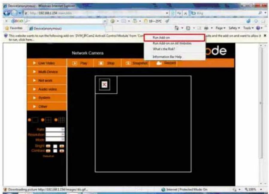
Figure 3.0

Note: If there is still no live video after you run ActiveX, and a red cross shows in the center of the screen, or even just a black screen, please try to enable the ActiveX options of IE security settings. (Did you install the ActiveX App from step 4 Figure 1.5?)
Please take the following steps:
- Close the firewall of your computer.
- Change the ActiveX settings, "IE" browser > "Tool" > "Internet Options" > "Security"> "Custom Level" > "ActiveX control and Plug-ins", all the ActiveX options set to be "Enable":
Especially:
Enable: Download unsigned ActiveX controls
Enable: Initialize and script ActiveX controls not marked as safe
Enable: Run ActiveX controls and plug-ins

Figure 3.1
In addition: you can also click "Start" menu->"Internet Explorer", choose "Internet attributes" to enter, or via "Control Panel" ->"Internet Explorer", enter to Security setting.
If you allowed the ActiveX running, but still could not see live video, only a Red Cross in the center of
the video, and the device status light change to yellow color, not green, please change another port number to try. Don't use port 80, use other port such as 128, 1008 etc.
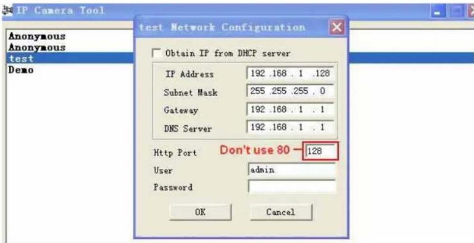
Figure 3.2
NOTE: Make sure that the firewall or anti-virus software doesn't block the software or ActiveX. If you couldn't see live video, please close your firewall or anti-virus software, and try again.
2.4 For Safari, Firefox, Google Browser
Choose Server Push Mode (For Safari, Firefox, Google Browser), and sign in.
Server Push Mode doesn't support ActiveX, so some functions are not available, such as Play, Stop, Record, etc. if you want to use these functions, please use IE browser.
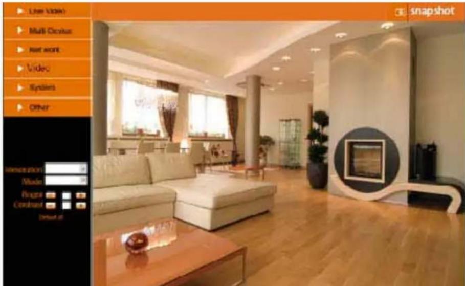
Figure 3.3
2.5 For Mobile Phone
Choose Sign in mobile phone, and sign in.
Mobile phone doesn't support ActiveX, only some basic functions can be available in this mode.
It supports Iphone, Smart phone, 3G phone etc. Normally, if the mobile phone supports network video, then it can work with our IP Camera.

Figure 3.4
2.6 ActiveX Mode (For Internet Explorer Browser)
Login to the camera in ActiveX mode, the main User Interface is as below:
NOTE: There are 3 levels of users, Visitor, Operator, Administrator, if you login with different users, the use authority is different. (See 3.11 User Settings, Figure 8.5).
2.7 For Visitor
When you login as Visitor, you can enter the IP Camera for visitor.
Visitor is the lowest level with only some operation available.
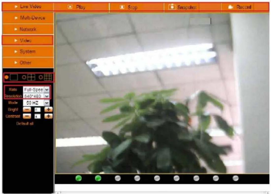
Figure 3.5
Channels:
The IE software supports 9 channels. Click

to get different windows.

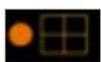

Click this one to view the main channel of the camera you login to.
Click this one to view 4 Channels of cameras that are connected, from CH1 to CH4.
Click this one to view 9 Channels of cameras that are connected, from CH1 to CH9.
NOTE: If you want to view 4/9 channels, you should set the Multi-Device first (See 3.1 Multi-Device Settings).
Status of Channels:
There are 9 icons at the bottom of the UI which show the status of each channel of the camera.

Grey color, means there is no device connected to the main device for this channel.

Green color, means the device is connected for this channel, and it works well.

Red color, means the device for this channel is recording.

Yellow color, means this channel is set in multi-device already, but it fails to connect to the main device.
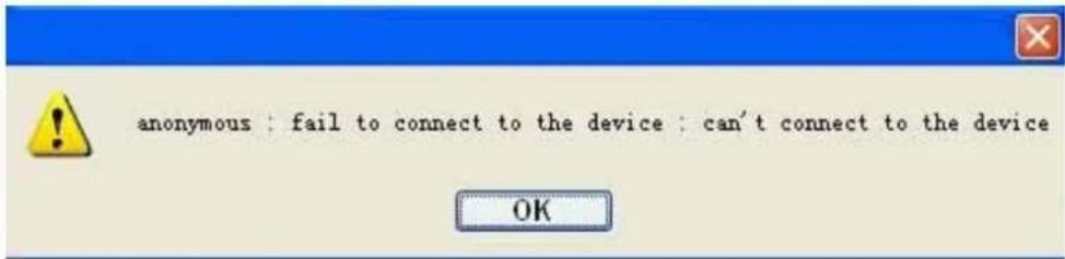
Figure 3.6
OSD Settings:
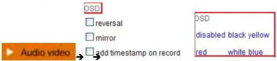
Figure 3.7
OSD: Means "On-Screen Display", click "Audio video" > "OSD", set display date and time on the video.
Disabled: Clicking this one means clear the OSD.
Color: Can set the OSD text color as black, yellow, red, white, blue etc.
Add time stamp on record: if you click this, there will be time OSD on record video files.

Figure 3.8
Rate and Resolution:
Rate: Set video frame here, from "full-speed to 1fp/5s". (Figure 3.9)
Resolution: Set the resolution to be 160*120/ VGA(640*480)/ QVGA (320*240). (Figure 4.0)
NOTE: When doing recording, Rate and Resolution parameter settings is very helpful for getting small size record files, the lower parameter to get the smaller file.
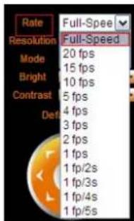
Figure 3.9
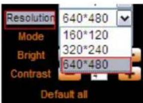
Figure 4.0
TOP Menu:

Figure 4.1

: Click it to get live video. When you want to back to live video from other menus, just click it.
Only under live video, you can do the operation on the right side, such as play, stop, snapshot etc.

: Click it to get into play mode, when you click stop icon, the video will be stopped, then click
play icon, it will show the video again.

: Click it to stop the live video. You can click play icon if you want to see live again.

: Click it to get snapshot. It will show the date and time of the snapshot you get, when you
want to save it, you will find the snapshot file named by "snapshot_MAC ID_date_time".

: Click it to start record by manual, and the icon will change to red color, click it again, it will
stop record. The record file will be saved to the folder you set. (Figure 10.6-Figure10.9)
NOTE: For visitor, if you click other menus which visitor don't have the right to operate it, there will be a pop-up of login interface (Figure 2.6), please input the user name / password for at least 3 times to login again.
2.8 For Operator
When login as Operator, you can enter the IP Camera for Operator.
For operator, it not only supports all the functions which for Visitor, and also supports these functions as below:

Figure 4.2
Video Settings
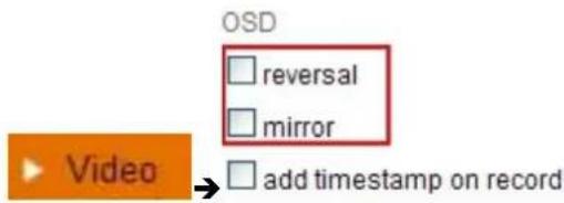
Figure 4.3
Reversal: Click this icon to see the reversal image. Click again, will back to normal.
Mirror: Click this icon to see the mirror image. Click again, will back to normal.
NOTE: You can choose Reversal and Mirror function when you set up the camera in a special position.
Mode, Bright, Contrast Settings
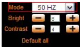
Figure 4.4
Mode: This is work mode optional, 50HZ/60HZ for the users who use 50HZ/60HZ frequency, outdoor for the users who want to use this camera to monitor toward outdoor environment
Bright: Set the parameters to adjust the image quality of video. Click - + to adjust the value
Contrast: Set the parameters to adjust the image quality of video. Click - + to adjust the value
Default all: Click it to set all the parameters back to factory setting.
NOTE: If you login the camera, there is no video displayed, and the parameter of bright/contrast is blank, maybe you can try to click "default all" to set the parameters back to factory setting to get live video.
NOTE: For Operator, if you click other menus which operator don't have the right to operate it, there will be a pop-up of login interface (Figure 2.6), please input the user name / password for at least 3 times to login again.
2.9 For Administrator
Details see Settings as Administrator (details3.1-3.20).
3 Settings as Administrator
When login as Administrator, you can enter the IP Camera for Administrator.
Administrator supports all the settings and operations of the camera; you can set and control it freely. There are some special functions only for administrator as below:

Figure 4.5
3.1 Multi-Device Settings
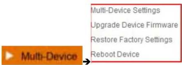
Figure 4.6
Multi-Device Settings
This camera can support max. 9 channels device at the same time.
3.1.1 Set Multi-Device in LAN
In the Multi-Device Settings page, you can see all devices searched in LAN. The 1st device is the default one. You can add more cameras listed in LAN for monitoring. This web software supports up to 9 IP Cameras online simultaneously.
Click The 2nd Device and click the item in the Device List in Lan, it will fill the Alias, Host, Http Port
automatically, then input the correct user name and password, click Add. Set more devices in the same way, after all done, please click Submit.

Figure 4.7
Click Live Video and then select to see four channels, or click nine channels.
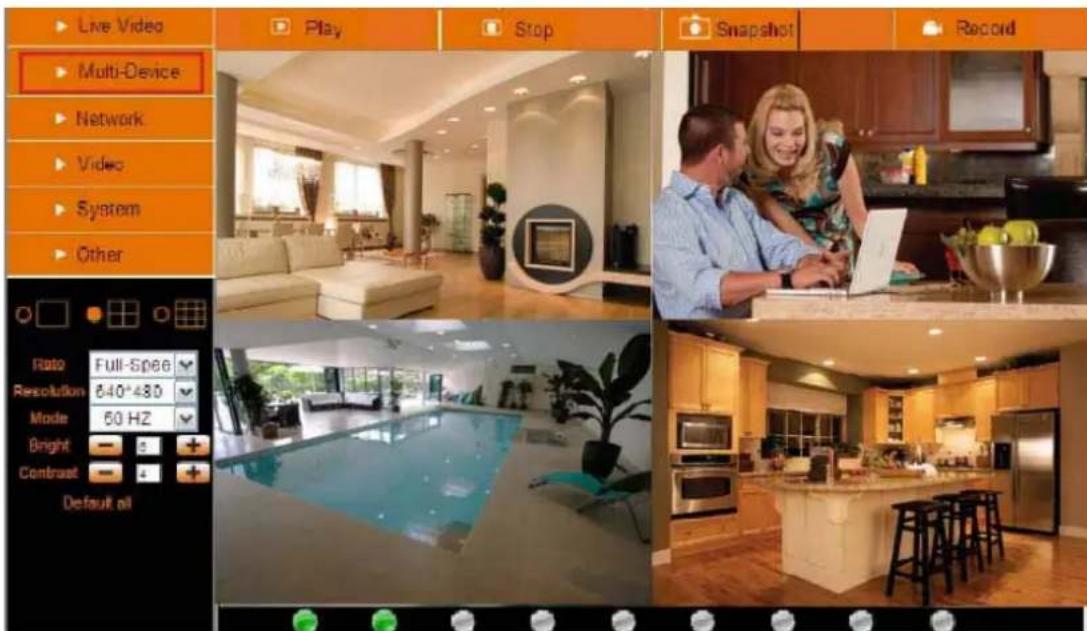
Figure 4.8

Figure 4.9
3.1.2 Set Multi-Device for WAN
If you want to view cameras from internet, you have to add these devices by DDNS domain name. Make sure all these cameras you want to add have been set DDNS successfully. (View 3.7 DDNS Service Settings) And also these cameras work well with DDNS.
Login the first camera by DDNS domain name and port, this camera will be as the host camera.

Figure 5.0
Click Multi-Device, select Multi-Device Settings. Choose the 2nd Device; fill in the 2nd camera's Alias, Host, Http Port, User, Password by manual, click Add. Set more devices in the same way, after all done, please click Submit.
NOTE: The Alias is optional; you can set the alias as per your wish. The Host must be the camera's DDNS domain name, and without "http://", it's not the Lan IP address.
If you have several cameras, you can use the same DDNS domain name, just set different port number for each different camera.

Figure 5.1
Note: Add the other camera in the same way, Click submit to add all of them.
| Multi-Device Settings | |
| Device List in Lan | anonymous(192.168.1.128) J019(192.168.1.136) anonymous(192.168.1.180) Demo (192.168.1.113) |
| The 1st Device | This Device |
| The 2nd Device | demo1(e0254.aipcam.com) |
| The 3rd Device | Apexis(Apexiscamera.3322.org) |
| The 4th Device | Anonymous(Apexisipcamera.dyndns.org) |
| The 5th Device | None |
| The 6th Device | None |
| The 7th Device | None |
| The 8th Device | None |
| The 9th Device | None |
| attention: If you want to access the device from internet, be sure the host and port that you set can be accessed from internet. Click Submit after submit Refresh finish all settings | |
Figure 5.2
Click Live Video and then select to see four channels, or nine channels. In this case, you can see all the cameras from a remote position by internet, for example, if you are on the business trip, you can use the first camera's (Host camera) DDNS to view all the devices via internet

Figure 5.3
3.1.3 Upgrade Device Firmware
If you want to upgrade the camera, please upgrade Device Firmware first, then upgrade Web UI.
Click Browse and choose correct bin file, then click Submit to do upgrading.
NOTE: Before doing upgrade via Browser, please make sure the IP Camera Tool of your computer could find the camera's IP.
Attention: Please must keep the power on during upgrading, and the better use wired mode. Please don't try upgrade freely, because wrong operation or incorrect upgrade bin file will damage the camera.

Figure 5.4
Click Restore Factory Settings, will pop-up a prompt, select OK, all the parameter will be returned to factory settings, and the device will reboot.


Figure 5.5
3.1.5 Reboot Device
Click Reboot the device, will pop-up a prompt, select OK, then the device will reboot
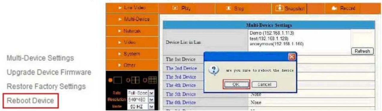
Figure 5.6
3.2 Network Settings
Click Network, will pop-up the prompt as below:

Figure 5.7
3.3 Basic Network Settings
Here you can fix the camera's IP address; means set the static IP address of camera manually. You can also do the same settings from IP Camera Tool. (Figure 2.3)
There are some good reasons to give the camera a static IP. The factory default setting is DHCP, this means that the network router will give the Camera an IP address itself for easy setup. The problem is that after a camera or network power loss the router may decide to give the camera a different IP address than the last time. If you want to login to the camera not using the IP Tool you don't know the camera's (new) IP address.

Figure 5.8
If you don't know Subnet Mask, Gateway, DNS Server. Please check the Local Area Connection Status of your computer; it contains all these information, steps as below:
- Control Panel→Network Connections→Local Area Connections→Support→Details

, because you might see more than one icon, left click it, choose
Support → Details
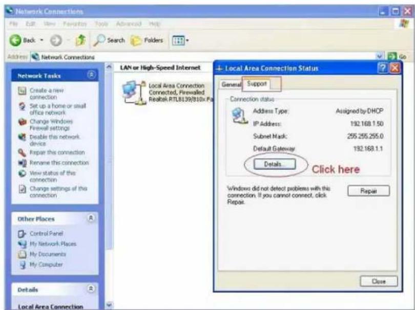
Figure 5.9
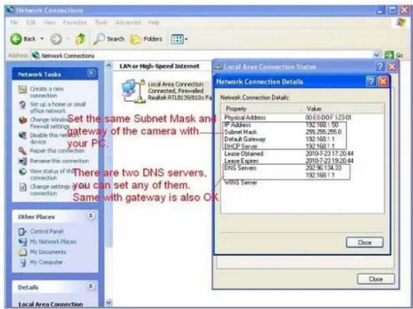
Figure 6.0
If you don't know the DNS Server, you can set it the same as Gateway.
If the router supports DHCP function, you can choose "Obtain IP from DHCP Server" to get dynamic IP.
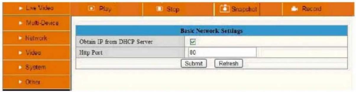
Figure 6.1
Http Port: In most cases your Internet Service Provider blocks this port(80), you may change it to another port number such as 85 or 86 or any number above 80. Make sure that if you have more than one camera it might be useful to give each camera a unique port number, but it's not necessary to do this.
3.4 Wireless Lan Settings

Figure 6.2
- Make sure the router is wireless router.
-
Make sure the Wi-Fi antenna installed.
-
Determine whether there is encryption on the WLAN of router, if there is encryption, note the key somewhere as we need it in the following steps.
Extra information:
Encryption is another word for password and security of the wireless network, most routers will have encryption these days (and should be) so other people cannot brake in to your network. Some routers have a sticker or the bottom with the factory username and password, other ones don't have a password, and the password can also be set by the user or mechanic. There is a very handy website with allot of router brand information like default IP address, default username and password etc. Please note we only refer to this website, we not maintain or support it. The website is: http://portforward.com/ Click "Router List" and find your brand and type to find more handy details about your router if you can't find them anywhere else.
In the next screenshots we take a Linksys router as an example, here Portforward.com shows the default username and password as well as the default IP address to visit the router settings menu.
Please note that Portforward.com is a website designed to tell you how to forward ports in your router. Information may vary from type to type of routers. Lets proceed shall we?

| 10096w | DCH | Lingo | SAMRE-4258 |
| 2671 | TrueMobile 2300 | Primero SAN-02ex. | SAMRE-4213 |
| 2671_A | TrueMobile 2350 | SART2-4112 | |
| 2700888E-2 | TrueMobile118+7 | SART2-4113 | |
| 2700kg | Digicom | Link-Max | SBRE-10100 |
| 2700HG-B | Michelangelo House 5i | L31541 | SW AMBE-54100 |
| 2700HG-D | Michelangelo-LAN-CS | SW AR12-54129 | |
| 2700HG-E | MichelangeloW.AVE | LinkPro | Sagem |
| 2700HG-S | MichelangeloW.pro-RL671 | WL-GNAAAR | 20045DC |
| 2701BC | Digiconnect | LinksKey | Fast-2404 |
| 2701HG-B | FAST-3001 | ||
| 2701HG-D | WIC328 | LKR-464 | Fast2500WCG |
| 2701HG-G | Fast2504 | ||
| 2701HG-S | Digitus | Linkxys | FastO3562 |
| 2701HG-T | Livebox-7359 | ||
| 2701HGV-B | DN-1180 4-4 | AG241 | Livebox-Fax-3282 |
| 2701HGV-E | DN-1180+N2 | AG266 | |
| 2701HGV-W | DN-1180+O | AMD89 | |
| 500HGV-B | DP-7039-A | AMD89 | |
| BE270HGV-Y | RP-4999 | BETC3CUB4 | SBS |
| BETD5B+IW | |||
| BETZ2P9A | BW 5159 | ||
| BETSR11 | |||
| BETSR11+I | |||
| BETSR41 | |||
| BETSR41+5+6+7 | |||
| BETSR41+5.48.2 | |||
| BETSR41+2 | |||
| BETSR81 | |||
| BETSR81+2 | |||
| BETSR81+3 | |||
| BETSR81+5 | |||
| BETSR81+3 | |||
| BETSR81 | |||
| BETSR81 | |||
| BETSR81 | |||
| BETSR81 | |||
| BETSR81 | |||
| BETSR81 | |||
| BETSR81 | |||
| BETSR81 | |||
| BETSR81 | |||
| BETSR81 | |||
| BETSR83 | |||
| BETSR83 | |||
| BETSR83 | |||
| BETSR83 | |||
| BETSR83 | |||
| BETSR83 | |||
| BETSR83 | |||
| BETSR83 | |||
| BETSR83 | |||
| BETSR83 | |||
| BETSR84 | |||
| BETSR84 | |||
| BETSR84 | |||
| BETSR84 | |||
| BETSR84 | |||
| BETSR84 | |||
| BETSR84 | |||
| BETSR84 | |||
| BETSR84 | |||
| BETSR84 | |||
| BETSR85 | |||
| BETSR85 | |||
| BETSR85 | |||
| BETSR85 | |||
| BETSR85 | |||
| BETSR85 | |||
| BETSR85 | |||
| BETSR85 | |||
| BETSR85 | |||
| BETSR85 | |||
| BETSR86 | |||
| BETSR86 | |||
| BETSR86 | |||
| BETSR86 | |||
| BETSR86 | |||
| BETSR86 | |||
| BETSR86 | |||
| BETSR86 | |||
| BETSR86 | |||
| BETSR86 | |||
| BETSR87 | |||
| BETSR87 | |||
| BETSR87 | |||
| BETSR87 | |||
| BETSR87 | |||
| BETSR87 | |||
| BETSR87 | |||
| BETSR87 |

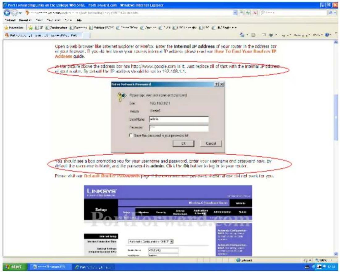
- Login to the camera with the IPCamera Tool or manual with your Browser.
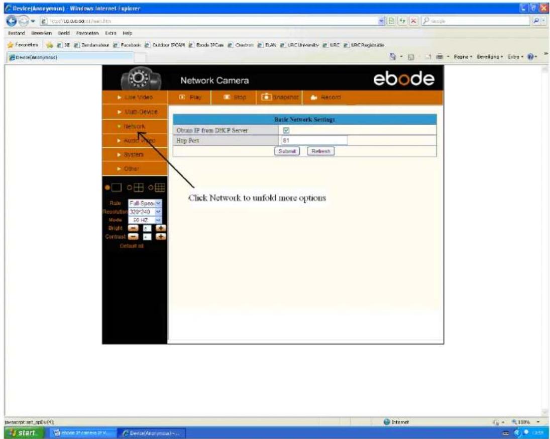
- Click "Network">"Wireless Lan Settings">"Scan", please press scan 2 times, then you will find the WLAN from the list, choose the one you use. (Figure 6.4).

Figure 6.1.1
![Device(Anonymous) - Windows Internet Explorer Last Stand Genderen Seed Favorites Extra Help Favorite/All XE Zendamateur Facebook Outdoor DPCAM Ebook DPCAM Crestron ELAR URC University URC URC Registration Device(Acronymous) Network Camera ebo de Live Video Multi-Device Network Audio video System Other Wireless Lan Settings Wireless Network List: BMB_Office[4e0000X2654] infra WPA/WPA2.PSK BMB_Office[00000X2654] infra WPA/WPA2.PSK Scan Dump Wireless Lan SSID Network Type Encryption Share Key BMB_Office Infra WPA Personal (AES) I Submit Refresh Send start ebo de IP camera IP v... Device(Acronymous) v... Internet](/content/2026/06/1258208/images/4d47d5c476d1e4ae9ddd8b1dfec307b2139e984f6212c1b44f0ec0e49bd18d5e.jpg)
Figure 6.2
Please note that the (tree view) menu (Figure 6.1.1) can look different on different computer systems depending on the resolution of the screen used. Figure 6.1.1 shows that we had to scroll over with our mouse and click "Network" inside the tree view on the left and that the options unfold in the tree view itself. After clicking "Network" you will see something like Figure 6.1.1.
- Select your Wireless network in the list, please look careful and select the right one.
"Wireless Lan" can also be referred as "SSID" in some router manuals or on the bottom of the router.
- Behind the SSID you can also find your type of encryption, in this particular case the Camera discovered: Network type "infra" Encryption "WEP".
![Wireless Lan Settings 123[002586745b2c] infra WEP 1[00258637ee26] infra None zhonglian[0025862c0bee] infra WEP t[e005c52b6934] infra None Scan](/content/2026/06/1258208/images/a16994b5b18d642b219f28e5d36488a4948ab0a7b10baa87d558791d6a3d9c9c.jpg)
- If there is no encryption, just click "Submit". (Figure 6.5)
- If there is encryption, please input the share key, then click "Submit". (Figure 6.6)
- Wait about 30 seconds, the camera will reboot, then unplug the network cable. You might have to login to the Camera again to continue with the next steps.
![Live Video Multi-Device Network Video System Other Wireless Lan Settings Basic Network Settings Wireless Lan Settings ADSL Settings UPnP Settings DCNS Service Settings 4 3 Scan 123[002586745b2c] infra WEP ChinaNet-RCUZ[00255e1dc55a] infra WPA/WPA 1[00258637ee26] infra None zhonglian[0025862c0bee] infra WEP 5 1 Network Type Encryption None 6 Submit Refresh](/content/2026/06/1258208/images/e85f92123ff6df338e94c87366e93da1e2054617e7c2c9fd899c333888e4fca7.jpg)
Figure 6.3
![Wireless Lan Settings Wireless Network List 123[002586745b2c] infra WEP 1[00258637ee26] infra None zhonglian[0025862c0bee] infra WEP t[e005c52b6934] infra None Scan Wireless router SSID list Using Wireless Lan ✓ SSID 1 Network Type Infra Encryption None Submit Refresh](/content/2026/06/1258208/images/9852de4d033d39ce2c401c7d4a319a0a1abc7bb6927e612817c09dba7f029c3c.jpg)
Figure 6.4
![Wireless Lan Settings Wireless Network List 123[002586745b2c] infra WEP 1[00258637ee26] infra None zhonglian[0025862c0bee] infra WEP t[e005c52b6934] infra None Scan Using Wireless Lan SSID 1 Network Type Infra No encryption Encryption None Submit Refresh](/content/2026/06/1258208/images/8438c8dd031b1384883292170a5c60b1c9526f56795308e07dfc7b0fcd0ec43c.jpg)
Figure 6.5
![Wireless Lan Settings Wireless Network List 123[002586745b2c] infra WEP 1[00258637ee26] infra None zhonglian[0025862c0bee] infra WEP t[o005c52b6934] infra None Scan Using Wireless Lan SSID 123 Network Type Infra Encryption WEP Authentication Open System Key Format Hexadecimal Number Default TX Key 1 Key 1 share key here 64 bits Key 2 64 bits Key 3 64 bits Key 4 64 bits Submit Refresh](/content/2026/06/1258208/images/8b1682999a31fe2ec930f91f8bef170ef6b02470e462c116e06ccb13e2b939cc.jpg)
Figure 6.6
3.5 ADSL Settings
When connected to the Internet through ADSL directly, you can enter the ADSL username And password obtained from ISP.

Figure 6.7
3.6 UPnP Settings
If we want to be able to see our camera live video from a computer outside our network, for example when we are at work, we have to do some advanced settings in our router. For most people this will be a difficult step, but we will try to help you out. UPnP stands for Universal plug n Play device. forwarding in the router for us, so we don't need to do this manually. In order to use this function we need to have a router that is capable of using UPnP devices. Please make sure your router supp check the manual of your router to determine if it supports UPnP), if not please skip the next step and continue with step 3.7 DDNS Service Settings. By default UPnP is most likely disabled in your router. Please r router manual to enable UPnP.
Click Network > UPnP Settings to choose Using UPnP to Map Port:

Basic Network Settings
Wireless Lan Settings
ADSL Settings
UPnP Settings
DDNS Service Settings

Figure 6.8
Select it and click Submit, then the camera will support UPnP port forwarding automatically.
It's helpful for using DDNS (viewing live video from outside our network). As soon as you have enabled UPnP in you router, please proceed with the next steps.

Figure 6.9
NOTE: UPnP is only for port forwarding. It relates to the security settings of your router, make sure the UPnP function of your router is enabled, before you continue. If your router does not support UPnP, it may show error information, therefore we recommend you to do port forwarding manually in your router, as explained in step 3.7.3.
3.7 DDNS Service Settings

Figure 7.0
Select Network > DDNS Service Settings in the Tree View on the left (see picture above)
There are 2 options:
Manufacturer's DDNS: This domain is provided with the Camera (see bottom of the camera). Choose 'submit'. In most cases you will need to login to the camera again. You can use the IPCamera tool for this or enter the Camera's IP address in your web browser. After you have done this, please skip the next step and continue with step 3.7.1
Third Party DDNS: You might have a DDNS server already, then it is useful to take the next steps.
This domain is provided by the third party, such as Dyndns, Oray, 3322 etc.
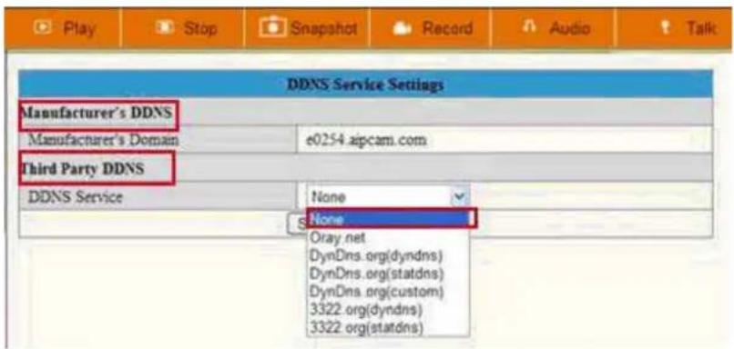
Figure 7.1
Third Party DDNS
If you use third party DDNS, please choose the server you use, such as "3322.org" or "dyndns.org" as below:

Figure 7.2
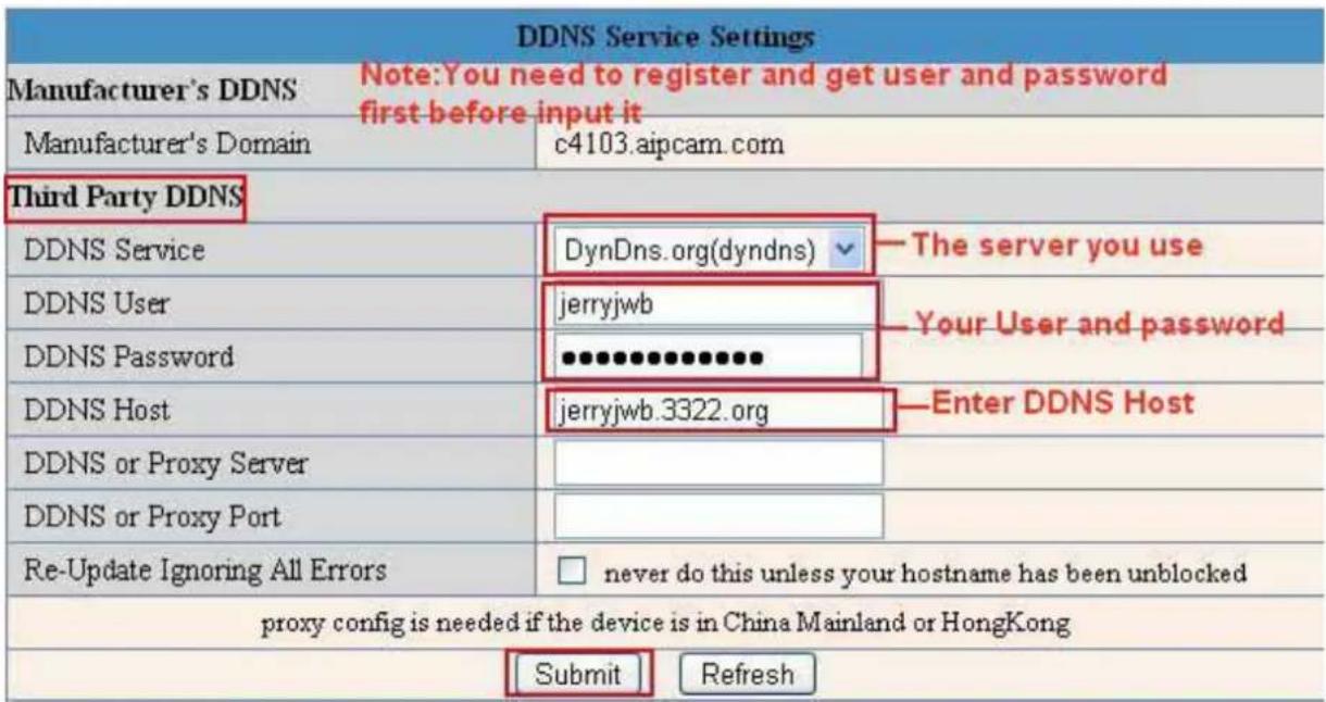
Figure 7.3
You have to register an account firstly, keep the user, password, host, then input it.
NOTE: Only one DDNS can be chosen, for example, if you use the manufacturer's DDNS, the third party one won't work, if you use the third party DDNS, the manufacturer's one won't work.
3.7.1 To change the camera's port.
Open the IP Camera Tool from your Desktop select the ebode camera (it will turn blue) and right-mouse click and choose network configuration. The default port of camera is "80", please change "80" to any other one you like, such as "81", "100", "8091" etc. Click "OK", the camera will reboot, wait about 30 seconds.
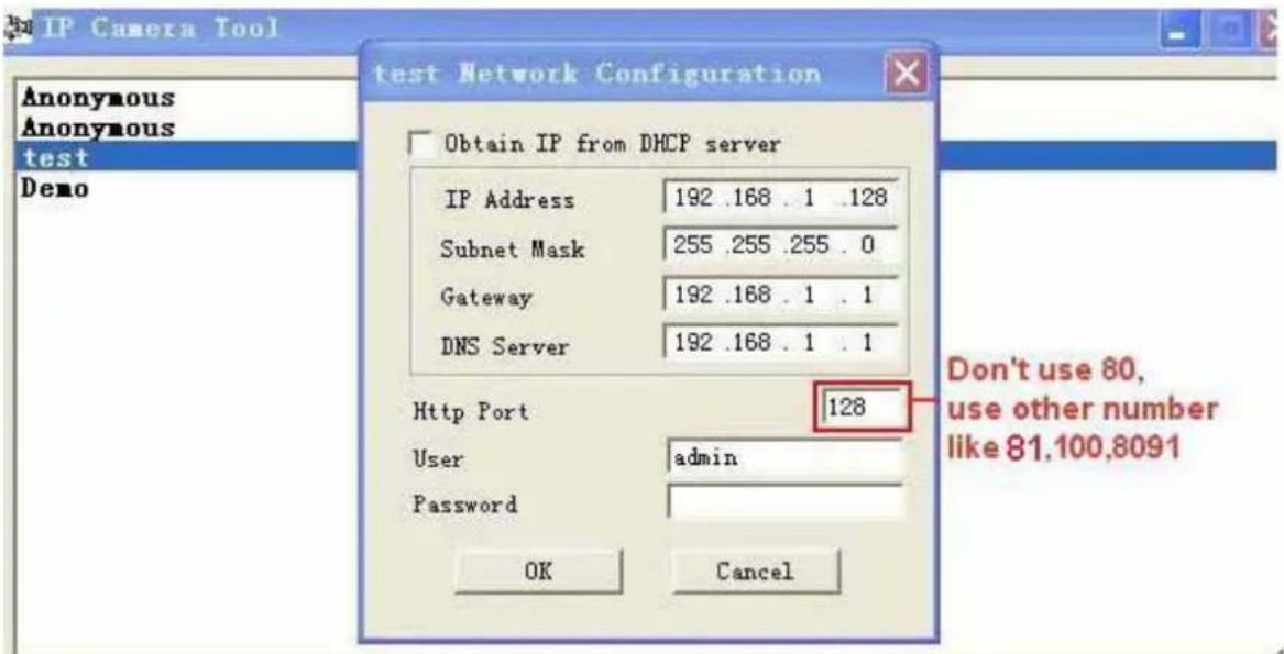
Figure 7.4
3.7.2 DDNS Status
After all these steps are done you should be able to access your camera from your mobile device or tablet (using an app). You can also access your camera via your computers' or laptops' web browser using the DDNS address.
Before you can access it, you first need to check the DDNS status from the camera. Login to the camera and choose "System">Device Info". Please check that 'DDNS Status' shows 'succeed' followed by the address. This is illustrated in the image below. It is important that you get the address link of DDNS to access the camera from anywhere in the world. You can also find this address on the bottom of your camera. Write this address somewhere or add is as your Favourite in your web browser to visit the camera from outside the network (from your mobile device for example at work, school, on the road etc.)

Figure 7.8
Congratulations! You've know successfully installed your IP camera. It is always a good idea to ask friends or family to login to the camera from their own place. Don't forget to change the password of the camera afterwards! Please save this manual for additional features. The following steps in this manual are only needed if the camera is not accessible from outside the network, or if you want to use additional features.
If it didn't succeed, it is most likely that UPnP is not supported by your router, please set the port for manually (as explained in the next step). You can always leave UPnP on, whether it's working or not. If DDNS status still doesn't show 'succeed' please check the FAQ, Chapter 4, at the back of this manual or our website www.ebodeelectronics.eu.
3.7.3 Set Port Forwarding in the router (Manually)
ADVISORY: We highly recommend you to give the ebode camera a static IP address. This ensures you that the camera will always have the same IP address, and reduces the risk of not being able to access and view the camera by your mobile device. To give your camera a static IP address, please check step 3.3 in this manual.
This is the most important step. Please check the 'extra information' in step 3.4 for more information about routers and port forwarding.
In order to get the DDNS to work, you have to forward your cameras port in the router. You need:
- IP address of the camera
- Port of the camera
- Default gateway IP address of the router
- Username and password of the router
The first two items can be found if you start up the IP Camera tool from your desktop. As an example the IP address from the below image is 192.168.1.16 and the port is 81.

REMEMBER: Your camera should not be on Port 80. If it is, please go to step 3.7.1 to change the port number.
How to discover the default gateway IP address in MS Windows Vista, 7: Click 'Start', and type in 'cmd', press enter. (see image below)

Next, type in 'ipconfig' and press enter. Please refer to below image.
![Microsoft Windows [Version 6.0.6002] Copyright (c) 2006 Microsoft Corporation. All rights reserved. C:\Users\MCE>ipconfig_](/content/2026/06/1258208/images/e9e1b9467f7ceff7d0bc8ab7e9459ccd131a99fbef12315bfccf4ee162630313.jpg)
Finally, you can see the default gateway address, as shown in the image below.

Now we know the default gateway address we only need to know the username and password of your router. Some routers have a sticker on the bottom with the factory username and password, other ones don't have a password, and the password can also be set by the user or mechanic. There is a very handy website with allot of router brand information like default IP address, default username and password etc. Please note we only refer to this website, we do not maintain or support it. The website is: http://portforward.com/ Click "Router List" and find your brand and type to find more handy details about your router if you can't find them anywhere else. For more information on portforward.com, please go to step 3.4.
We know have all information to get the DDNS working, we will show you how to do this.
- Open your web browser and type in the default gateway address and press enter.

- Enter the username and password from the router

- The next screen is the interface of your router. Please note that each brand of router has its own interface. This is just an example.

- Select NAT Setup. Please note that for each brand this can have a different name for NAT setup. Portforward.com contains more information about most router brands.
- Please choose 'Configure Port Redirection Table'

- Now we have to let the router know, on which port the camera is located.
Service name: give the camera a recognizable name, i.e. ebode IP Cam
Protocol: Select TCP
Public Port: You've checked this earlier on, please enter the right port for your camera (you can always use the IPCamera Tool to look it up, as explained at the beginning of this chapter)
Private IP: Is the IP address of the camera. Again, you can use the IPCamera Tool to look it up
Private Port: This is the same as public port
Please tick the box for 'active'
Then press ok
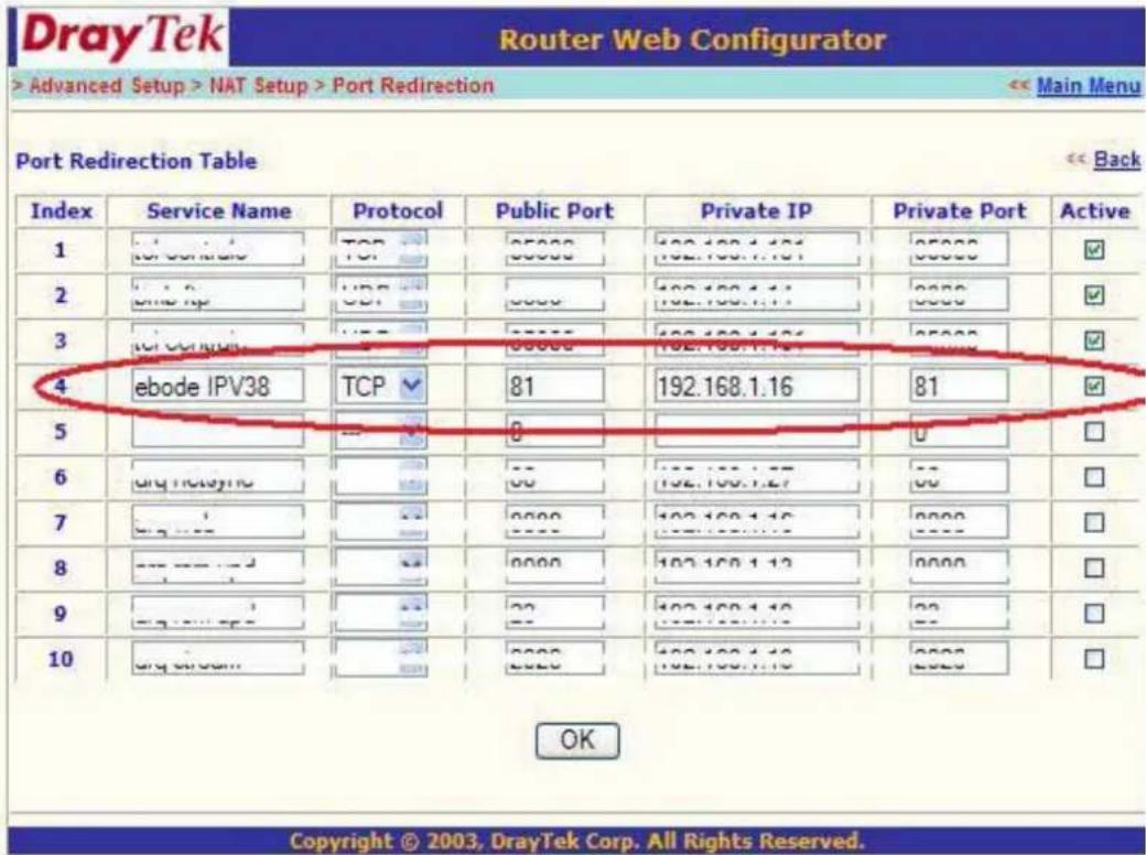
Now go to the DDNS Status from step 3.7.2 and check if it says 'succeed'. You should now be able to login to the camera from another location.
However, we showed you just one example, there are many different kinds of routers, therefore it's difficult to show fixed steps for each router, but here are some other samples of different router's port forwarding settings. Remember, portforwarding.com is a very useful source of information.
TP-LINK:
- Login the router.

-
Choose "Forwarding", select "Virtual Servers"
-
Click the Add New button, pop-up below:
Add or Modify a Virtual Server Entry
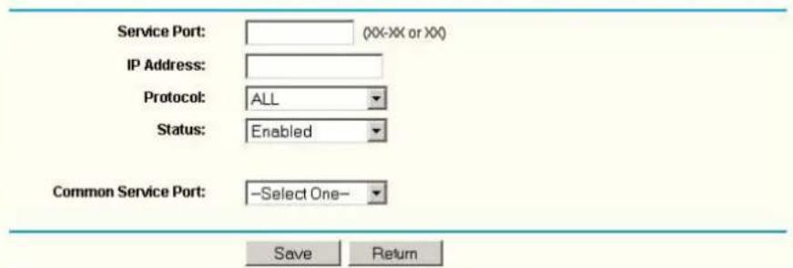
Figure 7.5
Fill the service port (except 80), IP address of the camera, then click Save
NOTE: The port and IP address should be the same as Camera.
BELKIN:
- Login the router.
- Choose "Firewall", select "Virtual Servers"
- Input the port (except 80) and IP address, then click save.
NOTE: The port and IP address should be the same as Camera.

Figure 7.6
DLINK:
- Login the router.
- Choose "Advanced", select "Virtual Servers"
- Input the port, IP address, Protocol, then click save.
NOTE: The "public port" & "private port" should be the same as camera's port, choose the protocol to be "both".

Figure 7.7
Now you are finished setting up your camera. The next steps explain additional features of your camera and FAQ.
3.8 System Settings

Figure 8.0
3.8.1 Device Info
You can find the information about Device ID, Firmware Version, Embedded Web UI Version, Alias, Alarm Status, DDNS Status, UPnP Status and MSN status..
| Device Status | |
| Device ID | 00606E8AF1C9 |
| Device Firmware Version | 17.25.2.30 |
| Device Embedded Web UI Version | 20.8.3.30 |
| Alias | demo |
| Alarm Status | None |
| DDNS Status | aipcam.com Succeed http://a5618.aipcam.com:191 |
| UPnP Status | No Action |
| Refresh | |
Figure 8.1
3.9 Alias Settings
Default device name is anonymous. You set any new name for your camera here, then click Submit.

Figure 8.2
3.10 Date & Time Settings
Set the date and time for your camera.
Choose the Clock Time zone of your country.
You can choose Sync with NTP Server (Figure 8.3) or Sync with PC Time (Figure 8.4).
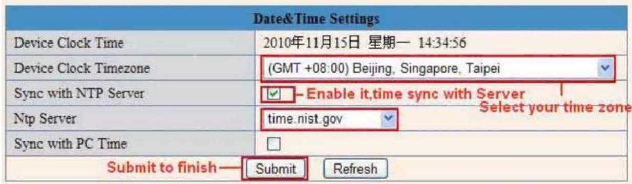
Figure 8.3

Figure 8.4
3.11 Users Settings
Eight accounts are acceptable for this system. Here you can set the user names and password as Administrator, Operator or Visitor, the permission for them as below:
- Visitor: In this mode, you can only view. (Details 2.7)
Operator: You can control the direction of IP Camera and set some parameter. (Details 2.8)
● Administrator: You can setup the advanced configurations of the IP Camera. (Details3.1-3.20)
| Users Settings | ||||
| User | Password | Group | ||
| admin | Administrator✓ | |||
| ipcam | ●●●●●● | Operator✓ | ||
| demo | ●●●●●● | Visitor✓ | ||
| Visitor✓ | ||||
| Visitor✓ | ||||
| Visitor✓ | ||||
| Visitor✓ | ||||
| Visitor✓ | ||||
| Visitor✓ | ||||
| Submit | Refresh | |||
Figure 8.5
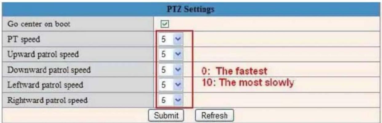
Figure 8.6
1) Backup: Backup IP Camera all the Parameter, if you want to save all the current settings that you have set already, you can click Submit, then all the parameters you set will store as a parameters bin file.
2) Restore: Restore IP Camera all the Parameter, if you want to change the camera's settings to a certain status which has a backup, click Browse to load the bin file, then Submit it.
Log
| Log | |||||
| Thu, 2010-11-04 20:03:00 admin 192.168.1.183 access | |||||
| Thu, 2010-11-04 20:03:38 admin 183.16.186.128 access | |||||
| Thu, 2010-11-04 20:15:01 motion detect | |||||
| Fri, 2010-11-05 08:48:09 motion detect | |||||
| Fri, 2010-11-05 10:26:11 admin 192.168.1.164 access | |||||
| Fri, 2010-11-05 12:27:53 motion detect | |||||
| Fri, 2010-11-05 21:00:04 motion detect | |||||
| Sat, 2010-11-06 09:01:15 motion detect | |||||
| Sat, 2010-11-06 09:35:47 admin 192.168.1.164 access | |||||
| Sat, 2010-11-06 09:41:36 motion detect | |||||
| Sat, 2010-11-06 11:21:03 admin 192.168.1.246 access | |||||
| Sat, 2010-11-06 12:05:09 motion detect | |||||
| Sat, 2010-11-06 12:10:23 motion detect | |||||
| Sat, 2010-11-06 12:23:35 admin 192.168.1.183 access | |||||
| Sat, 2010-11-06 12:29:39 admin 192.168.1.183 access | |||||
| Sat, 2010-11-06 12:33:35 admin 192.168.1.183 access | |||||
| Sat, 2010-11-06 12:33:44 admin 192.168.1.183 access | |||||
| Sat, 2010-11-06 12:51:06 admin 192.168.1.183 access |
Figure 8.8
Record User information, including weekday, date, time, user name, visitor IP address etc.
MSN Settings
| MSN Settings | |
| User | test@hotmail.com |
| Password | ●●●●●●● |
| MSN buddy list | ipcamtest@ hotmail .com |
| Submit Refresh | |
NOTE: Set the port forwarding successfully before setting MSN (Refer to port forwarding in DDNS settings). Then get to the MSN settings page, fill in the correct user name and password, add the MSN buddy, max. upto 10 friends, after submit, the user will be shown in your MSN friend list.
Click System—Device Info to check the MSN status.
| Device Status | |
| Device ID | 00EA2162836A |
| Device Firmware Version | 17.22.2.36 |
| Device Embedded Web UI Version | 20.8.1.82 |
| Alias | DEMO_011 |
| Alarm Status | None |
| DDNS Status | cipcam.com Succeed http://a5790.cipcam.com:91 |
| UPnP Status | UPnP Succeed |
| MSN Status | Succeed |
| Refresh | |
After it, run your MSN, open the chat dialog, type in the word "url?", after a few seconds, you will get a reply for the remote access ip address for this ip camera.
3.13 Other Settings

Figure 8.9
Here you can configure some additional functions such as Motion Detection, Alarm, IO Linkage, Schedule, FTP Upload, Alarm Mail Alert, Record Path etc.
3.14 Mail Service Settings
Set Mail Service Settings to enable the camera to send e-mail alerts when motion is detected.

Figure 9.0
Sender: Make sure the sender mailbox server provider support SMTP, and the mailbox should not enable SSL or TSL encryption too.
Receiver: Here you can set four receivers. For receiver, there is no SMTP limitation.
SMTP Server: The sender's SMTP Server.
SMTP Port: The sender's SMTP Port, usually is 25, some SMTP server have its own port such as 587.
Need Authentication: If there is SMTP user & password, please select authentication.
SMTP User: Input correct SMTP User here. Some SMTP User is the sender's full email address, such as test@qq.com, some are without suffix, only the username, such as test.
SMTP Password: Input correct SMTP password here.
NOTE: Please click Submit firstly before choosing Test.
You will see the test result after click Test.

Figure 9.1
If it shows the following errors when you click Test. Please check whether the information you filled in is incorrect and try again.
1) Cannot connect to the server.
2) Network Error. Please try later.
3) Server Error.
4) Incorrect user or password.
5) The sender is denied by the server. Maybe the server needs to authenticate the user, please check and try again.
6) The receiver is denied by the server. Maybe because of the anti-spam privacy of the server.
7) The message is denied by the server. Maybe because of the anti-spam privacy of the server.
8) The server does not support the authentication mode used by the device.
Report Internet IP by Mail: If select it, you will receive emails which contain the camera's internet IP. When camera power on or Internet IP changed, it will send the internet IP by mail. (For example: IPCAM's URL is http://121.213.109.69:1008).
3.15 FTP Service Settings
Set the FTP Service, you can upload images to your FTP server when motion detection triggered.

Figure 9.2
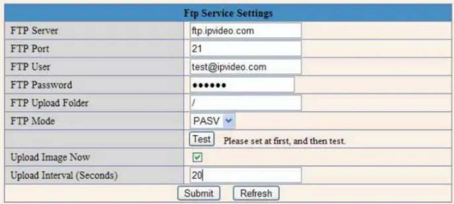
Figure 9.3
FTP Server: If your FTP server is set up in LAN. You can set as Figure 9.3.
If you have an FTP server that can be accessed from the Internet, you can set as Figure 9.4.
FTP Port: Usually the port is 21.
FTP Upload Folder: Make sure that the folder you plan to store images in exists. The camera cannot create the folder itself. Also, the folder must be erasable.
FTP Mode: It supports standard (POST) mode and passive (PASV) mode.
Upload Image Now: It will upload images when you selected it. Here Upload Interval refers to the time between the current image and the next image.
NOTE: Here upload image now means it can upload images freely, no alarm trigger needed.
Click Submit after these settings. Then click Test. You will see the following picture.

Figure 9.4
If it prompts error information as follows.
1) Cannot connect to the server. Please check FTP Server is correct.
2) Network Error. Please try later.
3) Server Error.
4) Incorrect user or password. Please check the username and password is correct.
5) Cannot access the folder. Please be sure the folder exists and your account is authorized.
6) Error in PASV mode. Please be sure the server supports PASV mode.
7) Error in PORT mode. PASV mode should be selected if the device is behind a NAT.
8) Cannot upload file. Please be sure your account is authorized.
Please check if parameters you filled in are correct. The format of image is like 000DC5D008FA (IPCAM)_0_20101115152525_25.jpg
Please check if your FTP server supports this format of file name.
3.16 Alarm Service Settings

Figure 9.5
Enter Alarm Service Settings page to configure Motion Detection function.
3.16.1 Motion Detect Armed
If you enable Motion Detect Armed, it will record and make an alarm sound when there is motion detected.
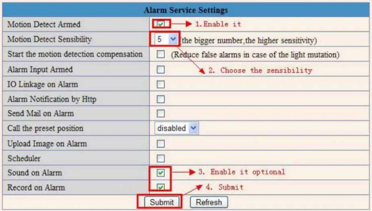
Figure 9.6
After you enable motion detect armed, if there is motion detected, the Alarm Status will turn to Motion Detect Alarm. (Figure 9.7)
| Device Status | |
| Device ID | 000DC5D008FA |
| Device Firmware Version | 0.22.2.20 |
| Device Embedded Web UI Version | 20.8.4.23 |
| Alias | Demo |
| Alarm Status | Motion Detect Alarm |
| DDNS Status | aipcam.com Succeed http://e0254.aipcam.com:8901 |
| UPnP Status | UPnP Succeed |
| Refresh | |
Figure 9.7
3.16.2 Motion Detect Sensibility
You can choose level 1-10; level 10 means the most sensitive, 1 means the least sensitive.

Figure 9.8
3.16.3 Alarm Input Armed / IO Linkage on Alarm
If you want to connect external alarm devices, when it's an alarm input device, choose Alarm Input Armed to enable it, when it's an output device, choose IO Linkage on Alarm to enable it.

Figure 9.9
There are two options for Trigger Level. (Figure 10.0)
High: When the external alarm device is close, then the alarm triggered.
Low: When the external alarm device is switching off, then the alarm triggered.

Figure 10.0
There are two options for Output Level. (Figure 10.1)
High: When chosen, the IO Pins work as a switch that is closed.
Low: When chosen, the IO Pins work as a switch that is switching off.

Figure 10.1
3.17 Send Mail on Alarm
When chosen, it will send picture and e-mail to your e-mail once alarmed. (First you should finish the e-mail Service Settings. Figure 9.1).
NOTE: It usually will send 6 snapshots by one e-mail to your mailbox for each alarm triggered. Each alarm will last for 60 seconds.
Upload Image on Alarm
Enable Upload Image on Alarm to set upload images to FTP once alarmed.
Upload Interval: Set the upload interval (Seconds).
NOTE: The total alarm time is 60 seconds.
| Upload Image on Alarm | ✓ |
| Upload Interval (Seconds) | 0 |
Figure 10.2
Scheduler
Here you can set the camera alarm during the time you set. Choose Scheduler and set the date & time range. (Figure 10.5) From Monday to Sunday, and every day divided into 24 hours, each hour divided into 4 quarters. Left click the frame of the time range, it will turn to blue color, which means the time you choose to be armed. Click it again, it will turn back to gray, which means delete the scheduler.
NOTE: Make sure the date & time settings are correct first. (Figure 8.3).
ATTENTION: If you don't choose Scheduler, the camera will alarm anytime when motion triggered.

Figure 10.3
Sound on Alarm
When motion is detected, there will be a beep sound during the alarm, you can control this sound here.
If Enabled, there will be sound once alarmed.
If Canceled, there will be no sound once alarmed.
Record on Alarm
If you want the camera to record for every alarm, choose Record on Alarm to enable it.
If you do not want the camera to record once the alarm is triggered, cancel it here.
| Sound on Alarm | ✔ |
| Record on Alarm | ✔ |
Figure 10.4
Once alarm occurred, there will be some representation:
- The corresponding status light turns Red and keeps blinking.

Figure 10.5
- If you set Sound on Alarm, plug an earphone or a speaker to the computer you use, you can hear the beep sound when alarmed. (Figure 10.4)
- If you set Record on Alarm, the camera will record automatically for approx one minute. You can find the record file in the folder which you set. (Figure 10.4)
- If you set Send Mail on Alarm, you will receive email alarm alert once motion triggered. (Figure 9.9)
- You can also set Scheduler to enable the camera sends emails during a special time range you want. (Figure 10.3)
- If you set Upload Image on Alarm, it will upload images to the FTP Server you set already once alarmed. (Figure 10.2)
NOTE: Each alarm only lasts for approx one minute, all the above functions for motion detection triggered only.
REC Automatically and Save to PC
When you enable motion detect and open the camera monitoring page on the PC. If there is an alarm triggered, REC will start automatically for several seconds and save to the PC.
New Feature: Start the motion detection compensation and Alarm notification by Http.
3.18 Path Settings
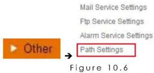
Here you can set record path and alarm record path for the camera.
| Path Settings | ||
| Record Path | E:\ | Browse... |
| Alarm Record Path | E:\ | Browse... |
Figure 10.7
Record Path: Here you can set the manually record path. Click Record, then start manually record, the record file will be saved to the specified path here set.
Alarm Record Path: Here you can set the alarm record path. When the motion triggered, and record enable, it will start alarm record automatically, the record file will be saved to the specified path here set.

Figure 10.8
NOTE: If you couldn't set the path here in Windows 7 or Vista, please do it as below:
Windows 7 or Vista's security level is higher than Windows XP, for "Path Settings"
- User could add the Device IP address to the IE's 'Trusted sites' firstly. The step is:
"IE browser→Tool→Internet Proper→Security→Trusted sites→Sites→Add".
- You can also run the IE as administrator, input the IP address of the camera manually. (Figure 10.9)
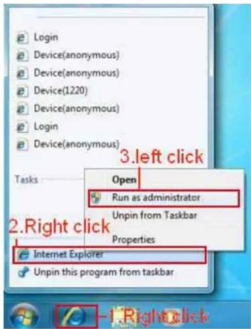
Figure 10.9
3.19 Server Push Mode (For Safari, Firefox, Google Browser)
Choose Server Push Mode, login the camera, you will see the main user interface as below:
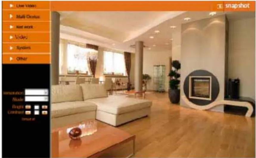
Figure 11.0
NOTE: Server Push Mode does not support ActiveX.
Play, Stop, Record, Multi-device settings, Path settings functions are controlled by ActiveX, so if you use Safari, Firefox, Google chrome browser, it is impossible to find these options.
The other functions are the same as ActiveX Mode (For IE Browser)
3.20 Sign in mobile phone
If you are using a mobile phone, choose Sign in mobile phone, login the camera, you will see the main user interface as below:

Figure 11.1
NOTE: Mobile phone Mode doesn't support ActiveX.
In mobile phone mode, it only supports some easy functions, such as Resolution, Mode, Bright, Contrast, Snapshot, Reversal, Mirror functions
Compatible Apps for mobile devices
Please, keep checking the App store regularly; soon we will be introducing our own ebode app for the IP camera, which gives you even more functionalities! Search for ebode IPVision!
In the meantime, for this IP camera, you can use the following apps:
IP Vision from Marcio Almeida (paid)
CamViewer from John McKerrell (free)
4.0 APPENDIX
4.1 Frequently Asked Questions
Note: For most problems you might encounter, please check Network connections first.
Check the working status revealed by the indicators on the network server, hub, exchange and network card. If abnormal, check the network connections.
4.1.1 I have forgotten the administrator username and/or password.
To reset the administrator username and password, press and hold down the RESET BUTTON for 15 seconds. Release the power button and the username and password will be reset back to the factory default administrator username and password.
Default administrator username: admin
Default administrator password: None, i.e., no password
4.1.2 Subnet doesn't match, double click to change
If IP Camera Tool shows error information "Subnet doesn't match, double click to change!" Please choose Obtain IP from DHCP server. (Figure 2.2)
If it still show this error after obtain IP from DHCP server. Please check local area connection of your computer, change subnet, gateway of the camera. Keep them in the same subnet of your computer. (Figure 2.3)
4.1.3 IP Address configuration
Check whether IP address of the IP camera server shares the same subnet as your work station: Click My Computer >Control Panel> Network & Dial-up Connections > LAN > Attributes >Internet Protocols (TCP/IP), and check IP Address and Subnet Mask. Make sure they are in the same subnet when configuring the camera's IP address manually.
4.1.4 Can't access IP camera in internet
There are some reasons:
1 ActiveX controller is not installed correctly (see more details: Figure2.9\~Figure3.1).
2 The port that the camera is using is blocked by your Firewall or Anti-virus software. Please change to another port number and try again. (Figure3.2)
3 Port forwarding is not successful (see more details: Figure7.5\~Figure7.9)
Double check these settings and make sure they are correct.
4.1.5 IP Camera Tool could not find camera's IP
Make sure the camera is connected to its power supply and the power supply is plugged in.
Check if the network cable is not loose.
Make sure DHCP is enabled in your router, don't enable MAC address filter.
Make sure that firewall or anti-virus software does not block the camera. You can add the camera as a trusted site in your firewall or anti-virus software.
4.1.6 UPnP always failed
UPnP only contains port forwarding in our recent software. Sometimes, it might fail to do port forwarding automatically because of firewall or anti-virus software. It also relates to your router's security settings. So we
recommend you do port forwarding manually. You can view your camera via the Internet successfully after you do port forwarding manually in your router.
4.1.7 Couldn't find the shortcut on desktop after install IP camera tool
If you use Windows 7 or Vista, and you could not find the shortcut on desktop after installing the IP camera tool, please check if the path of the tool port to is correct.
For example, was it was pointing to C:\Windows\System32\IPCamera.exe
Please fix this by pointing the shortcut to the correct path C:\Windows\SysWOW64\IPCamera.exe. After this you should be able to use the shortcut without any problems.
4.1.8 I can't change the record path
When you use Windows7 or Vista, you may be not able to change the record path for the security settings of computer.
- Please add the camera as a trusted site to solve this issue.
The step is: "IE browser→Tool→Internet Proper→Security→Trusted sites→Sites→Add". - You can also run the IE as administrator; input the IP address of the camera manually.
4.1.9 I can't find multi-device settings and record icon
Record and multi-device function are controlled by activeX controller.
So if you use Safari, Firefox, Google chrome, it is impossible to use these functions.
4.1.10 Camera can not connect wireless
If your camera could not connect wirelessly after you set wireless settings and unplug the Network cable:
Please check whether your settings are correct. (Details: Wireless LAN settings).
If the camera can't connect wirelessly it is usually because of wrong settings.
Double check the SSID, Encryption share key, Channel, should be the same as your wireless router.
Share key should not contain special characters, only letters and numbers.
Don't enable MAC address filter.
4.1.11 I can't see other cameras which in multi-device when remote access
If you want to view all the cameras in your WAN. Make sure that each camera you add in multi-device settings can be logged-in using DDNS name and port number. Use DDNS domain name to fill in the host checkbox, not camera's LAN IP. Double check your settings. (Details: Set Multi-Device for WAN).
4.1.12 I only see black screen or unusual code when remotely logged in
If you could access the login page in a remote place, it indicates that your DDNS settings are correct. But if you could not see live video, but only some undefined characters, it may be internet speed problems, especially if the camera works OK via Wi-Fi.
4.1.13 There's no picture (Problems with ActiveX Controller)
If using IE browser to connect the camera for the first time, and there is no image displayed, you might need to install ActiveX. You need to change some browser settings to enable ActiveX. (See: For IE Browser).
4.1.14 Problems with network bandwidth
The image frame rate is subjected to the following factors:
-
Network bandwidth
-
PC performance, network environment and display preference setting (brightness, theme, etc)
- The number of visitors (Too many visitors will slow down the image frame rate)
- Choice of switch or hub (Use a switch for multiple IP Camera Servers rather than a HUB)
4.1.15 How to register an account from DDNS web
You can enter http://www.dyndns.com and register an account.
4.1.16 Pop-up the prompt" Fail to connect to the device..."?
This prompt only appears in the case of using multiple cameras.
When you set multiple cameras, and the device status light changes to yellow please make sure the cameras are connected to power and working correctly.
4.2 Default Parameters
Default network Parameters
IP address: dynamic
Subnet mask: dynamic
Gateway: dynamic
DHCP: Disabled
DDNS: factory DDNS and third party DDNS
Username and password
Default administrator username: admin
Default administrator password: None, i.e., no password
- Specifications
| Model IP Vision 58 | |
| Image Sensor | |
| Sensor 1/4" Color CMOS Sensor | |
| Resolution | 640 x 480 Pixels (300k Pixels) |
| IR Lens | f: 6mm, F 2.0 (3.6mm lens optional) |
| Viewing Angle | 60 Degree (3.6mm lens is 90Degree) |
| Minimum Illumination | 0.5Lux @ F2.0 |
| Video / Image Setting | |
| Video Compression MJPEG | |
| Video Frame Rate | 15fps(VGA), 30fps(QVGA) |
| Resolution | 640 x 480(VGA), 320 x 240(QVGA) |
| Flip Mirror Images | Vertical / Horizontal |
| Light Frequency | 50Hz, 60Hz or Outdoor |
| Video Parameters | Brightness, Contrast |
| Communication | |
| System Interface | 10Base-T/100Base-TX Ethernet Port |
| Supported Protocol | TCP/IP , DHCP , SMTP , HTTP , DDNS , UPNP , PPPoE, FTP, DNS, UDP, GPRS |
| Wireless LAN | Support wireless network (Wi-Fi/802.11/b/g) |
| WEP Encryption | Disable / 64 bit / 128 bit |
| WPA/WPA2 Encryption | TKIP / AES |
| Physical / Environment | |
| Power Supply | 5VDC/2A External Power Adapter |
| Power Consumption | 5W (Max.) |
| Operate Temperature | -10°C ~ 55°C (14°F~131°F) |
| Operate Humidity | 20%-85% non-condensing |
| Storage temperature | -10°C ~ 60°C (14°F~140°F) |
| Storage Humidity 0%-90% non-condensing | |
| PC System Requirement | |
| CPU | 2.0GHZ or above |
| Memory Size | 256MB or above |
| Display Card | 64M or above memory |
| Supported OS | Microsoft Windows 98/ME/2000/XP/Vista/7 |
| Browser | IE6.0, IE7.0, IE8.0, Firefox, Safari, Google chrome etc |
| Certification | CE, FCC, RoHS |
| Warranty | Limited 1year warranty |
6. OBTAINING TECHNICAL SUPPORT
We hope your experience with your IP network camera is enjoyable, but if you experience any issues or have any questions that this User's Guide has not answered, please visit www.ebodeelectronics.eu or e-mail info@ebodeelectronics.eu.
This manual is based on the latest version of the camera at it's release. Updates might become available overtime, so make sure you always make sure to run the latest firmware version for your camera in order to obtain support.
If your camera does not support some special functions shown in this manual, please contact our technical support team to obtain the latest Firmware and WEB UI file for upgrading.
DECLARATION OF CONFORMITY
Hereby, ebode declares that this IP Vision 58 is in compliance with the essential requirements and other relevant provisions of the following Directives:
1) Directive 1999/5/EC of the European Parliament and of the Council of 9 March 1999 on radio equipment and telecommunications terminal equipment and the mutual recognition of their conformity
2) Directive 2004/108/EC of the European Parliament and of the Council of 15 December 2004 on the approximation of the laws of the Member States relating to electromagnetic compatibility
3) Directive 2006/95/EC of the European Parliament and of the Council of 12 December 2006 on the harmonization of the laws of Member States relating to electrical equipment designed for use within certain voltage limits
4) Directive 2002/95/EC of the European Parliament and of the Council of 27 January 2003 on the restriction of the use of certain hazardous substances in electrical and electronic equipment
5) Directive 2005/32/EC of the European Parliament and of the Council of 6 July 2005 establishing a framework for the setting of eco design requirements for energy-using
Technical data and copies of the original Declaration of Conformity are available and can be obtained from ebode electronics: PB 25, NL-4264ZG, the Netherlands.
CE
User Information for Consumer Products Covered by EU Directive 2002/96/EC on Waste Electric and Electronic Equipment (WEEE)
This document contains important information for users with regards to the proper disposal and recycling of ebode products. Consumers are required to comply with this notice for all electronic products bearing the following symbol:
Environmental Information for Customers in the European Union
European Directive 2002/96/EC requires that the equipment bearing this symbol on the product and/or its packaging must not be disposed of with unsorted municipal waste. The symbol indicates that this product should be disposed of separately from regular household waste streams.
It is your responsibility to dispose of this and other electric and electronic equipment via designated collection facilities appointed by the government or local authorities. Correct disposal and recycling will help prevent potential negative consequences to the environment and human health.
For more detailed information about the disposal of your old equipment, please contact your local authorities, waste disposal service, or the shop where you purchased the product.

DECLARATION OF CONFORMITY TO R&TTE DIRECTIVE 1999/5/EC
for the European Community, Switzerland, Norway, Iceland and
Liechtenstein
Product category: general consumer (category 3).
English: This equipment is in compliance with the essential requirements and other relevant provisions of the European R&TTE Directive 1999/5/EC
Also available from ebode: LightSpeaker
The Next Bright Idea
The unique ebode LightSpeaker™ cleverly combines low consumption LED lighting with wireless sound in one easy 'plug and play' system that can be hidden away in a lampshade or light fitting. Install it into any room in just a few minutes without tools or extra wiring!

natural_image
Product photo of a white LED light bulb with attached control panel and remote control (no text or symbols visible)LightSpeaker™ can be mounted into many different light fixtures including pendants fittings, table and floor lamps.
It can even be recessed into your ceiling using our custom-made fitting. All you need is an iPod™, HiFi, television or PC to provide your music and a standard E27 socket to plug into, and this multiroom, two source system will deliver brilliant lighting and tuneful music around your home - free of wires and headphones.

natural_image
Interior view of a modern dining table with white chairs, a hanging lamp, and potted plants (no visible text or symbols)How it works
Up to two music sources - an iPod ^TM and a radio for example, can be connected to the transmitter in the base station, which wirelessly sends the sound to the LightSpeakers ^TM which are screwed into a standard E27 socket to receive their power.
The wireless transmitter base station or the supplied remote control allow you to control your source, music and lighting levels from anywhere in your home. Up to four pairs of LightSpeakers™ can be 'paired' to one base station.
Also available from ebode: Home Automation Modules
ebode offers a wide range of Home Automation products and solutions which help you control your ‘electrical environment’. The home automation modules are ideal to (remotely) control blinds/rollers, home cinema screen, lighting, and other household appliances.
On-Wall Modules
| Product | Description | |
| EM 2-position RF wall switch, ideal for retro fit installations to e.g. control blinds, shutter, home cinema screens but also lighting or appliances. |  | |
| IMRF Single position RF wall switch, ideal for retro fit installations to e.g. control applications or an inside or outside light. |  | |
| RMV | Control your shutter, blind or e.g. cinema screen via the front panel keys, or remotely via any ebode / X10 compatible controller. |  |
| RMA | Control your appliance, light or e.g. pump via the front panel keys, or remotely via any ebode/X10 compatible controller. |  |
| RPA, RPL, RPT | Ideal for retro fit installations, the classic X10 plug-in module in a new and stylish jacket. Control your appliance or lamps etc, via any ebode or X10 compatible controller via PLC AND RF! |  |
| TPC / TMML | New stylish RF remote to control any ebode or X10 compatible RF receiver. | [ME] |
In-Wall Modules
| Product | Description | |
| EMML | 2-position RF in-wall module to install behind any mechanical wall switch. The EMML is battery operated. |  |
| RMML | In-wall RF receiver, ideal for any switches lights and appliances up to 300W. |  |
ebode
www.ebodeelectronics.eu


- Outdoor IP Camera with Night Vision IP Vision 58
- Index
- WELCOME
- Features
- Packing List
- Product Views
- Front View
- Rear Panel
- Bottom View
- PC System Requirements
- Hardware Instruction
- Software Installation
- SOFTWARE OPERATION
- IP Camera Tool
- Six Options
- .1 Basic Properties
- Network Configuration
- Upgrade Firmware
- Refresh Camera List
- Flush Arp Buffer
- About IP Camera Tool
- Camera Login
- For Safari, Firefox, Google Browser
- For Mobile Phone
- ActiveX Mode (For Internet Explorer Browser)
- For Visitor
- Channels:
- Status of Channels:
- OSD Settings:
- TOP Menu:
- For Operator
- Video Settings
- Mode, Bright, Contrast Settings
- For Administrator
- Settings as Administrator
- Multi-Device Settings
- Multi-Device Settings
- Set Multi-Device in LAN
- Set Multi-Device for WAN
- Upgrade Device Firmware
- Reboot Device
- Network Settings
- Basic Network Settings
- Support → Details
- Wireless Lan Settings
- Extra information:
- ADSL Settings
- UPnP Settings
- DDNS Service Settings
- Third Party DDNS
- To change the camera's port.
- DDNS Status
- Set Port Forwarding in the router (Manually)
- TP-LINK:
- BELKIN:
- DLINK:
- System Settings
- Device Info
- Alias Settings
- Date & Time Settings
- Users Settings
- Other Settings
- Mail Service Settings
- FTP Service Settings
- Alarm Service Settings
- Motion Detect Armed
- Motion Detect Sensibility
- Alarm Input Armed / IO Linkage on Alarm
- Send Mail on Alarm
- Upload Image on Alarm
- Scheduler
- Sound on Alarm
- Record on Alarm
- REC Automatically and Save to PC
- Path Settings
- Server Push Mode (For Safari, Firefox, Google Browser)
- Sign in mobile phone
- Compatible Apps for mobile devices
- APPENDIX
- Frequently Asked Questions
- I have forgotten the administrator username and/or password.
- Subnet doesn't match, double click to change
- IP Address configuration
- Can't access IP camera in internet
- IP Camera Tool could not find camera's IP
- UPnP always failed
- Couldn't find the shortcut on desktop after install IP camera tool
- I can't change the record path
- I can't find multi-device settings and record icon
- Camera can not connect wireless
- I can't see other cameras which in multi-device when remote access
- I only see black screen or unusual code when remotely logged in
- There's no picture (Problems with ActiveX Controller)
- Problems with network bandwidth
- How to register an account from DDNS web
- Pop-up the prompt" Fail to connect to the device..."?
- Default Parameters
- Default network Parameters
- Username and password
- OBTAINING TECHNICAL SUPPORT
- DECLARATION OF CONFORMITY
- CE
- User Information for Consumer Products Covered by EU Directive 2002/96/EC on Waste Electric and Electronic Equipment (WEEE)
- Environmental Information for Customers in the European Union
- DECLARATION OF CONFORMITY TO R&TTE DIRECTIVE 1999/5/EC
- for the European Community, Switzerland, Norway, Iceland and
- Liechtenstein
- Also available from ebode: LightSpeaker
- How it works
- Also available from ebode: Home Automation Modules
- ebode
Brand : EBODE
Model : IPV58
Category : Surveillance Camera