
MDR1064 - Mixer SAMSON - Free user manual and instructions
Find the device manual for free MDR1064 SAMSON in PDF.


| Product Type | Audio Mixer |
| Model | MDR1064 |
| Brand | Samson |
| Number of Channels | 10 |
| Inputs | 10 mono mic/line channels (XLR & 1/4" TRS), 2 stereo returns |
| Outputs | Main stereo outputs (XLR), 4 subgroup outputs, 2 aux sends, phones output |
| Equalization | 3-band EQ per channel (Hi, Mid, Low) |
| Effects | Built-in digital effects processor with 16 presets |
| Phantom Power | +48V switchable per channel |
| Power Supply | Internal power supply, 110-240V AC, 50/60Hz |
| Dimensions | 19" rackmount, 3U height, approximately 17" depth |
| Weight | Approximately 12 lbs (5.4 kg) |
| Construction | Steel chassis with rugged knobs and switches |
| Cleaning & Maintenance | Clean with a soft dry cloth. Do not use solvents or abrasive cleaners. |
| Safety | Read the user manual before use. Do not expose to rain or moisture. Operate in a well-ventilated area. |
| Spare Parts & Repairability | Contact Samson customer service for authorized repair or replacement parts. |
Frequently Asked Questions - MDR1064 SAMSON
User questions about MDR1064 SAMSON
0 question about this device. Answer the ones you know or ask your own.
Ask a new question about this device
Download the instructions for your Mixer in PDF format for free! Find your manual MDR1064 - SAMSON and take your electronic device back in hand. On this page are published all the documents necessary for the use of your device. MDR1064 by SAMSON.
USER MANUAL MDR1064 SAMSON
MDR1064 Maximum Dynamic Range

TEN CHANNEL MIXER
Owners Manual
Safety Instructions/Consignes de sécurité/Sicherheitsvorkehrungen/Instrucciones de seguridad
WARNING
DO NOT EXPOSE THIS EQUIPMENT
TO RAIN OR MOISTURE
AVIS
RISQUE DE CHOC ELECTRONIQUE
NE PAS OUVRIR
CAUTION
FOR CONTINUED PROTECTION AGAINST RISK
OF FIRE, REPLACE ONLY WITH SAME TYPE FUSE
ATTENTION
UTILISER UN FUSIBLE DE
RECHANGE DE MÊME TYPE

CAUTION
RISK OF ELECTRIC SHOCK
OF ELECTRIC'S DO NOT OPEN

WARNING: To reduce the risk of fire or electric shock, do not expose this unit to rain or moisture. To reduce the hazard of electrical shock, do not remove cover or back. No user serviceable parts inside. Please refer all servicing to qualified personnel. The lightning flash with an arrowhead symbol within an equilateral triangle, is intended to alert the user to the presence of uninsulated "dangerous voltage" within the products enclosure that may be of sufficient magnitude to constitute a risk of electric shock to persons. The exclamation point within an equilateral triangle is intended to alert the user to the presence of important operating and maintenance (servicing) instructions in the literature accompanying the product.
Important Safety Instructions
- Please read all instructions before operating the unit.
- Keep these instructions for future reference.
- Please heed all safety warnings.
- Follow manufacturers instructions.
- Do not use this unit near water or moisture.
- Clean only with a damp cloth.
- Do not block any of the ventilation openings. Install in accordance with the manufacturers instructions.
- Do not install near any heat sources such as radiators, heat registers, stoves, or other apparatus (including amplifiers) that produce heat.
- Do not defeat the safety purpose of the polarized or grounding-type plug. A polarized plug has two blades with one wider than the other. A grounding type plug has two blades and a third grounding prong. The wide blade or third prong is provided for your safety. When the provided plug does not fit your outlet, consult an electrician for replacement of the obsolete outlet.
- Protect the power cord from being walked on and pinched particularly at plugs, convenience receptacles and at the point at which they exit from the unit.
- Unplug this unit during lightning storms or when unused for long periods of time.
- Refer all servicing to qualified personnel. Servicing is required when the unit has been damaged in any way, such as power supply cord or plug damage, or if liquid has been spilled or objects have fallen into the unit, the unit has been exposed to rain or moisture, does not operate normally, or has been dropped.
Front and Rear Panel Layout 4
Front and Rear Panel Controls 5
Controls and Functions
Mono/Stereo Input Channel Section 6–7
Master Section 8–9
MDR1064 Input and Output Connections 10–11
Operating the MDR1064 12–14
System Set-ups 15–16
MDR1064 Wiring Guide 17
Specifications 18
Block Diagram 19
Notes 20
Copyright 2004, Samson Technologies Corp.
Printed February, 2004
Samson Technologies Corp.
575 Underhill Blvd.
P.O. Box 9031
Syosset, NY 11791-9031
Phone: 1-800-3-SAMSON (1-800-372-6766)
Fax: 516-364-3888
www.samsontech.com
Introduction
Congratulations on your purchase of the Samson MDR1064 mixer! The MDR1064 is a ten-channel mixer, with six low noise microphone pre-amps. The six Mic/line inputs and two stereo inputs each feature a 3-band equalizer plus two Aux sends. The MDR1064's master section includes two stereo Aux returns and a 2-tack Input and Output for playing back stereo devices and for recording your mix. Clean, clear sound reproduction with sweet equalization and signal flexible routing in a rugged enclosure, ensure reliable high quality sound from performance to performance. Optimized for recording, live sound reinforcement and commercial installations, the MDR1064 is an ideal mixer solution offering big sound in a compact package.
In these pages, you'll find a detailed description of the features of the MDR1064 mixer, as well a description of its front and rear panels, step-by-step instructions for its setup and use, and full specifications. You'll also find a warranty card enclosed—please don't forget to fill it out and mail it in so that you can receive online technical support and so we can send you updated information about these and other Samson products in the future.
With proper care and adequate air circulation, your MDR1064 will operate trouble free for many years. We recommend you record your serial number in the space provided below for future reference.
Serial number:
Date of purchase:
Should your unit ever require servicing, a Return Authorization number (RA) must be obtained before shipping your unit to Samson. Without this number, the unit will not be accepted. Please call Samson at 1-800-3SAMSON (1-800-372-6766) for a Return Authorization number prior to shipping your unit. Please retain the original packing materials and if possible, return the unit in the original carton and packing materials.
MDR1064 Features
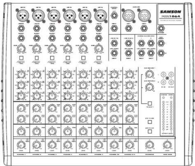
The Samson MDR1064, ten-channel mixer is a comprehensive, all-in-one solution for live sound, recording, fixed installation and post production applications. Here are some of its main features:
- Eight Channels – Six Mic/Line plus two Stereo inputs with mic pre's.
- Flexible design topology ideal for live sound, recording and post production.
• 2 Track Input and Output allows you to connect a CD, DAT, Cassette, Mini Disk or Computer Sound Card.
- Three-band channel equalizer, +/-15dB at 80Hz, 2.5 KHz and 12KHz provides precise and musical results in sound shaping.
• Two Auxiliary Sends for built-in or external effects, on-stage monitor mix, or headphone mixing.
- Twelve segment LED Meter with VU ballistics displays the main MIX output.
• High quality, low noise, discrete microphone pre-amplifiers with 48-Volt phantom power, provide Maximum Dynamic Range and transparent audio.
• Advanced circuit design using discrete components and high quality, low noise op-amps carefully selected at each stage of the signal path.
• Quality build and rugged construction ensure reliable performance from venue to venue and session to session.
• Three-year extended warranty.
Front and Rear Panel Layout


Front and Rear Panel Controls
FRONT PANEL
① MIC IN – Input connector for Low-Noise Microphone pre-amp.
② LINE IN-Input connector for Line level inputs.
③ INSERT – 1/-4-inch TRS (TIP/RING/SLEEVE) connector providing send and recieve channel patch point for outboard effects.
④ GAIN – Used to set the input level of the mic pre and line input.
⑤ LOW CUT – Bass roll off switch at 75Hz used to eliminate unwanted low end rumble and hum.
6 HIGH FREQUENCY – Controls the high band of the Channel Equalizer, +/- 15 dB at 12KHz.
⑦ MID FREQUENCY – Controls the mid band of the Channel Equalizer, +/- 15 dB at 2.5KHz.
⑧ LOW FREQUENCY – Controls the low band of the Channel Equalizer, +/- 15 dB at 80Hz.
⑨ AUX 1 – Pre-fader auxiliary send that can be used with an external effects processor, or to create a cue or monitor mix.
⑩ AUX 2 – Post-fader auxiliary send that can be used with an external effects processor, or to create a cue or monitor mix.
11PAN – Controls the channel's position between left and right in the stereo bus.
12 PEAK – Red LED will illuminate indicating when the GAIN has been adjusted too high.
13 LEVEL – Audio taper fader provides smooth control over level changes.
14 RIGHT LINE – 1/4-inch phone input connector for the right line input for the stereo channels.
15 LEFT LINE - 1/4-inch phone input connector for the Left Line input for the stereo channels.
16 CONTROL ROOM OUTPUT— Left and Right Control Room output connectors for connecting a monitor system.
⑰ MAIN MIX OUTPUT (1/4-inch) – Left and Right Main Mix balanced output 1/4-inch TRS connectors.
⑱ MAIN MIX OUTPUT (XLR) – Left and Right Main Mix balanced output XLR connectors.
⑲19 PHONES JACK – Connect stereo headphones here.
⑳ AUX SEND 1 – Line level output from the Auxiliary 1 bus.
②1 AUX SEND 2 – Line level output from the Auxiliary 2 bus.
22 AUX RETURN 2 – Left and right input jacks for connecting to the outputs of external line level sources like those from effects processors.
23 AUX RETURN 1 – Left and right input jacks for connecting to the outputs of external line level sources like those from effects processors.
242 TRACK OUTPUTS – Connect to the input of a DAT, Cassette, Mini Disk or Hard Disk Recording system.
252 TRACK INPUTS – Connect the output from a DAT, Cassette, Mini Disk or Hard Disk Recording system.
26POWER LED – Indicates the MDR1064 is powered up.
27 PHANTOM LED – Indicates that the 48 Volt Phantom Power is on.
28 OUTPUT METER - Twelve segment LED display with VU ballistics indicates main Mix level.
⑲MAIN LEVEL – Used to control the overall volume of the Left and Right main Mix outputs.
30 PHONES/CR – Adjusts the volume of the control room speakers or headphones.
312 TRACK TO CR – Switches between the main Mix and the 2 Track in the Control Room output.
③22 TRACK TO MIX - Switch used to mix the 2 track input with the mix from the channel inputs.
33 TO AUX 1 - Switch used to route aux return 2 into the Aux 1 output so that effects can be heard in the monitor mix.
34 AUX RETURN 2 – Used to mix in level of the effects return.
35 AUX RETURN 1 – Used to mix in level of the effects return.
36 BALANCE – Controls the channel's position between left and right in the stereo inputs.
REAR PANEL
A POWER – Switches on the MDR1064's main power.
B PHANTOM – Engages the 48-Volt Phantom power supply to microphone pre-amps.
© AC ADAPTOR INLET – Connect External AC power supply here.
Controls and Functions
MONO/STEREO INPUT CHANNEL SECTION
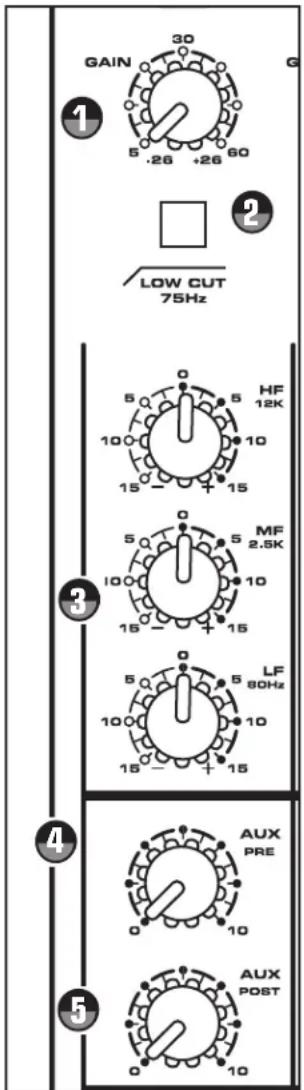
The following section details each part of the MDR1064's MONO INPUT CHANNELS including the GAIN control, LOW CUT switch, 3-BAND EQ, AUX sends, PEAK LED, PAN and LEVEL controls. The input channels one through six on the MDR1064 feature high quality, discrete transistor pre-amp providing transparency and extended dynamic range.

GAIN
The MDR1064's pre-amp stage has a variable GAIN control with a range of 5 to 60dB on the MIC input and -26 to +26dB on the LINE input.

LOW CUT FILTER
Each of the MDR1064's first six channels include a LOW CUT (or high pass) filter which rolls off the low frequencies from 75Hz and below at the rate of 18dB per octave. The LOW CUT filter allows you to remove the lower frequencies that you sometime just don't want to pick up. For example, when you are miking a high-hat you only want to capture the frequencies that the hi-hat is producing. Therefore, by using the LOW CUT filter, you can reduce the amount of pick-up from the low toms and bass drum that may leak into the hi-hat mic. You can use the same technique on other instruments like acoustic guitar, violin, piano and even on vocals. In live sound applications, the LOW CUT filter is especially useful for removing stage rumble.

CHANNEL EQUALIZER
The MDR1064 input channels feature a 3-band equalizer allowing you to adjust the high, mid, and low frequencies independently on each channel. The channel's frequency response is flat when the knobs are in the "12:00" position. Rotating the knob towards the right will boost the corresponding frequency band by 15dB, and rotating it towards the left will cut the frequency by 15dB. The frequency centers, range of boost or cut, and equalizer type for each band are as follows:
High: 12KHz +/- 15dB shelving type
Mid: 2.5KHz +/- 15dB peaking type
Low: 80Hz +/- 15dB shelving type

AUX 1
The MDR1064 has two auxiliary sends which can be used for sending signals to external effects devices or for creating a monitor mix. The AUX1 section is often used for a monitor mix in a live sound mixing, or for a headphone mix in a recording application. Each input channel includes an AUX 1 send which controls the amount of that channel's signal that is sent to the AUX bus.
NOTE: The AUX1 controls are "PRE-FADER SENDS" which means they are not affected by the FADER level settings of each channel. This allows you to create a mix for the monitors that is independent of the main LEFT and RIGHT MIX.

AUX 2
The channel's AUX 2 knob controls the amount of signal that is sent to the AUX 2 bus. The AUX 2 signal can be sent to an external effects device connected to the AUX 2 OUT jack located in the MASTER SECTION jack field.
Controls and Functions
(MONO/STEREO INPUT CHANNEL CONTINUED)
NOTE: The channel's AUX 2 signal is sent to the AUX 2 bus from a location in the signal path after the channel's LEVEL control. This is commonly referred to as a POST FADER send. This means that the amount of signal that is sent to the AUX 2 bus will be affected not only by the setting of the AUX 2 knob control, but it will also be affected by the setting of the LEVEL control.

BALANCE (Stereo Inputs Only)
The MDR1064's BALANCE control is used to place or position the stereo signal into the main Left and Right MIX bus. You can move a stereo signal's image to the left or right by setting the BALANCE control to the left or to the right.


PAN (Mono Inputs Only)
The MDR1064's PAN control is used to place or position the mono signal into the stereo main Left and Right MIX bus. You can create a stereo image by panning some input signals to the left and others to the right. The MDR1064's PAN control is a Power-Pan circuit, which includes a 3dB dip in the center position. This is desirable since there's a 3dB increase in gain when the mono input signal is heard in both the Left and Right MIX bus.

PEAK LED
The MDR1064's MIC/LINE pre-amp also includes a PEAK LED which, when illuminated, indicates that the signal is peaking or overloading. To reduce distortion, lower the GAIN control to keep this LED from staying on.

CHANNEL LEVEL
The MDR1064's LEVEL control knobs are used to adjust the overall channel volume.

Controls and Functions
MASTER SECTION

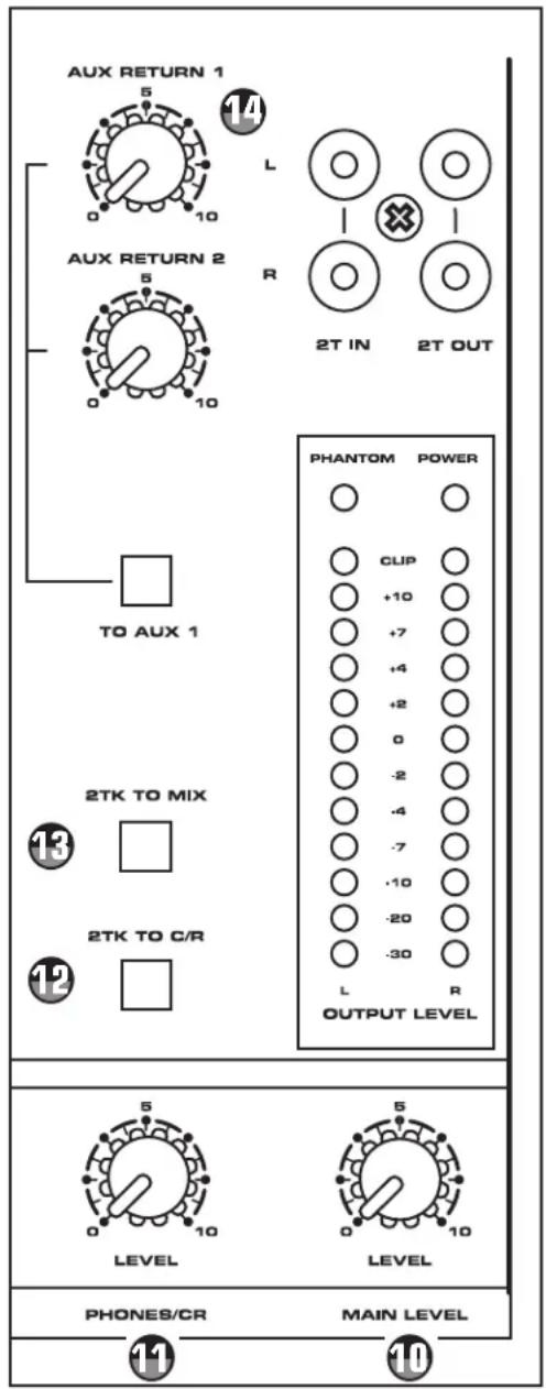
MAIN LEVEL
The master MAIN control is the overall volume control for the left and right mix bus. These line level signals are output from the MAIN MIX jacks.

PHONES / CR
The PHONES / CR control is used to set the level sent to the control room outputs, and also to the headphone jack.
2 TRACK INPUT AND OUTPUT
The MDR1064's 2 Track section provides the connections for playback and recording for an external device such as a DAT, cassette recorder, CD or Mini Disk.

2TK TO CR
The 2TR TO CR switch is used to assign the 2TR input to the Control Room output. If you push down the 2TK TO CR button, signal will be routed into the left and right Control Room output and will be adjusted by the CR / PHONES control knob.

2TK TO MIX
The 2TR TO MIX switch is used to assign the 2TR input to the MAIN mix bus. If you push the 2TR TO MIX button, the signal present at the 2 TRACK IN will be routed to the left and right MAIN output and the level will be controlled by the MAIN LEVEL knob.
Auxiliary Returns
The MDR1064 has two stereo auxiliary returns, which can be accessed via the two pairs of 1/4-inch phone jacks located on the master section jack field. The auxiliary returns can be used to connect any stereo line level signal, but they are primarily used to connect the output of external effects processors.

AUX RET 1
This adjusts the amount of signal that is sent from the AUX 1 RET jacks to the MAIN bus.
Controls and Functions
MASTER SECTION (continued)

AUX RET 2
The AUX RETURN 2 adjusts the level of the signal present at the AUX 2 RET jacks. This signal is summed, or mixed in to the main L/R MIX bus.

TO AUX 1
This routes the signal that is present on the AUX 2 RETURN jacks to AUX 1 so that the effects can be heard in the monitor mix.

POWER LED
The Power LED lights up to indicate that the main POWER switch (located on the rear panel) is on.

Phantom Power LED
This LED illuminates indicating that the 48 volt phantom power is applied to the microphone pre-amps enabling use with condenser microphones. The +48V LED will light up when the Phantom Power switch (located on the rear panel) is switched to the ON position.

Output Level Meter
The OUTPUT LEVEL METER allows you to monitor the level of the signal which is being sent to the MIX OUT jacks.
NOTE: To avoid distortion, adjust the Main Level control so that the 0 indicator LED lights occasionally.

MDR1064 Input and Output Connections
CHANNEL 1 - 6 MIC and LINE INPUTS
The MDR1064's channel 1 through 6 mono inputs each have a 1/4-inch connector for line level signals and XLR connectors for the MIC signals. Channels 7/8 and 9/10 stereo inputs each have 1/4-inch connectors for line level inputs. By using the GAIN control on channels 1 through 6, you can connect a variety of signal sources from microphones to line level devices such as synthesizers, and drum machines. All the LINE and MIC inputs are balanced. The MIC inputs are compatible with microphones with output impedances of 50-600 Ohms and the LINE inputs are compatible with line level devices of 600 Ohms. Following below is a detailed description of the MDR1064's input and output connectors.
NOTE: It is not possible to simultaneously use both the LINE and MIC inputs on the same channel. Use only one of the inputs for the appropriate source on each channel.

Microphone Input - Mono Input Channels
Use these inputs to connect Low Impedance microphones and low level signals from direct boxes. The MIC inputs have a nominal operating level of -50dBu through -20dBu. The MIC inputs also feature +48V phantom power, allowing you to use condenser microphones. The Phantom Power switch (located on the MDR1064's rear panel) enables phantom power on all the microphone inputs when set to the ON position. XLR Connector pin-out - Pin 1: Ground, Pin 2: Hot (+), Pin 3: Cold (-)

Line Level Input - Mono Input Channels
Use these inputs to connect synthesizers, drum machines, effects processors or any line-level signal. The LINE inputs have a nominal operating level of -40dBV through -10dBV. TRS phone jacks Connector pin-out - Sleeve: Ground, Tip: Hot (+), Ring: Cold (-)

Insert Point Jack - Mono Input Channels
The MDR1064's mono input channels feature a 1/4-inch TRS INSERT jack providing a patch point to connect an external processor. You can use these connections to interface an external signal processor like an equalizer, compressor, noise gate, reverb and other audio devices. For more information on the channel INSERT points, see the section, "Using the Channel Insert Jacks" on page 13 of this manual.

Line Level Input - Stereo Input Channels
You can connect the outputs from stereo devices such as synthesizers, drum machines, effects processors or any stereo line-level signal. Use the LEFT input when connecting a mono input signal to the Stereo Input channels. The LINE inputs have a nominal operating level of -40dBV through -10dBV. TRS phone jacks Connector pin-out - Sleeve: Ground, Tip: Hot (+), Ring: Cold (-)

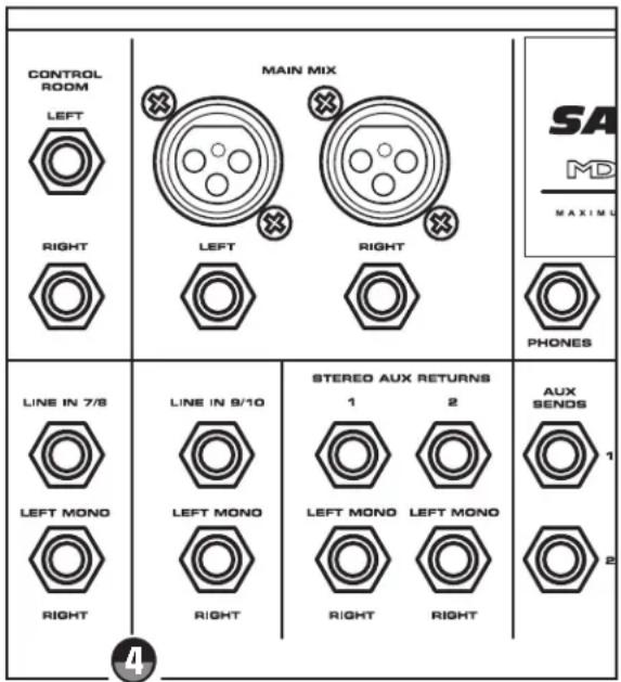
MASTER SECTION INPUT AND OUTPUT JACKS
The MDR1064 features several output connectors allowing you to interface a variety of external devices. A stereo recording device, such as a cassette recorder, can be connected to the 2 Track jacks, and power amplifiers or powered monitors can be connected to the CONTROL ROOM and MAIN output jacks.
MDR1064 Input and Output Connections

In a live sound application, the LEFT/ RIGHT MIX outputs are connected to a power amplifier or powered speak-
ers. In a recording application, the LEFT/ RIGHT MIX outputs are used to connect to the inputs of a stereo device such as computer sound card, DAT, or cassette recorder.

In a live sound application, the LEFT/ RIGHT MIX outputs are connected to a power amplifier or powered speakers. In a recording application, the LEFT/ RIGHT MIX outputs are used to connect to the inputs of a stereo device such as computer sound card, DAT, or cassette recorder.

CONTROL ROOM LEFT/RIGHT OUTPUT
The Control Room outputs are used to connect a studio monitor system. The Control Room outputs have the same output as the L/R MIX, however, the level can be adjusted independently from the main mix using the C ROOM/HEADPHONES control.

HEADPHONE OUTPUT

You can connect a standard pair of stereo headphones to the PHONES jack and depending on the position of the 2T TO CR switch, you will hear either the 2-Track input or the MAIN mix.

AUX Send 1
The signal present at the AUX1 output is sent from the AUX1 bus, which is fed from the AUX 1 send on the input channels. The AUX 1 output can be used as the EFFECTS SEND bus in a live sound situation by connecting the output to a power amp an external effects device.

AUX Send 2
The signal present at the AUX 2 output is sent from the AUX 2 bus, which is fed from the AUX 2 send on the input channels. The AUX 2 output can be used as the MONITOR MIX bus in a live sound situation by connecting the output to a power amp and monitor speaker.

AUX RETURN 2 LEFT/RIGHT
The AUX RETURN 2 LEFT/RIGHT are stereo inputs that are generally used to connect the outputs of an effects processor, but can also accept the signal from any line level source like a keyboard, recorder and even another mixer. The signal connected to the AUX RETURN 2 LEFT/RIGHT will feed the main LEFT/RIGHT MIX bus. The overall level is controlled by the AUX RET 2 knob located in the master section on the front panel. Use the LEFT/MONO input when connecting a mono input signal to the AUX RETURN.

AUX RETURN 1 LEFT/RIGHT
The AUX RETURN 1 LEFT/RIGHT are stereo inputs that are generally used to connect the outputs of an effects processor, but can also accept the signal from any line level source like a keyboard, recorder and even another mixer. The signal connected to the AUX RETURN 1 LEFT/RIGHT will feed the main LEFT/RIGHT MIX bus. The overall level is controlled by the AUX RET 1 knob located in the master section on the front panel. Use the
LEFT/MONO input when connecting a mono input signal to the AUX RETURN.

2TR INPUT
The MDR1064 features dual RCA connectors for the left and right 2-track input. You can use these inputs to connect a CD, Cassette, Mini Disk, DAT or the output from a computer sound card. To listen to the input connected to the 2T IN, be sure to check the position of the 2T To Mix and 2T TO CR switches. For more information on using the 2 Track inputs, see the section "PLAYING BACK A CD USING 2T TO MIX" on page 14 of this manual.

2TR OUTPUT
If you want to record the mix from your MDR1064, you can use the 2-track OUT connectors. The dual RCA connectors can be connected to a CD, Cassette, Mini Disk, DAT or even the input of a computer sound card for hard disk recording. For more information on
using the 2 Track outputs, see the section "RECORDING A MIX FROM THE MDR1064" on page 14 of this manual.

Operating the MDR1064
BASIC OPERATION
The following section explains the basic operation of the MDR1064.
CONNECTING MICROPHONES AND INSTRUMENTS
-
Before connecting mics or instruments, make sure that the power of all your systems components including the MDR1064 is turned off. Also, make sure that the MAIN LEVEL and PHONES / CR controls are turned all the way down.
-
Connect the cables to your microphones and instruments, and insert the other end of the cable firmly into the appropriate input on the MDR1064.
NOTE: SETTING THE INPUT GAIN - When connecting a microphone to channels 1 through 6, it's a good idea to start with the Gain Control turned all the way down. Set the input fader to the "0" position and slowly raise the GAIN control until you see the CLIP LED turn on. Now, back the GAIN control down so that the CLIP LED only lights for a short time during the loudest input the channel will see.
- Switch on the power of any peripheral devices, and then power up the MDR1064.
NOTE: It is important to remember the Golden Rule of audio ... " LAST ON, FIRST
OFF". Translated, this means that when turning on your system, you should always turn your power amplifiers or powered monitors on LAST, and when turning your system off, turn your power amps off FIRST. This helps avoid any loud pops caused by rush current at power up, or down, which can sometimes damage loudspeakers.
-
Turn on your power amp or powered monitors and raise the level control to the manufacturers recommended operating level.
-
Set the MAIN LEVEL control in the MDR1064's master section to the "5" position.
-
While speaking into the mic (or playing the instrument), adjust the channel LEVEL control so that the "0" LED of the MAIN section VU level meter lights occasionally.
-
You can shape the tone of each channel by adjusting the equalizer controls as desired.

NOTE: You may need to adjust the channel LEVEL control to compensate for the slight changes in level after using the channel equalizer.
Operating the MDR1064
SENDING AN INDEPENDENT MIX TO THE MONITOR SPEAKERS
The MDR1064's AUX1 auxiliary send can be used to feed a separate set of amplifiers and loudspeakers for stage monitors. This lets you build one mono mix for the amplifiers and monitor speakers facing the musicians, and the other stereo mix for the amplifiers and speakers facing the audience.
- Raise the AUX1/MON controls for the channels that you wish to hear from the monitor speakers.
NOTE: The AUX1 controls are "PRE-FADER SENDS" which means they are not affected by the level settings of each channel. This allows you to create a mix for the monitors that is independent of the main LEFT and RIGHT MIX.
- In order to get the most gain from your monitor mix, use an external graphic equalizer (like a Samson S curve 131) to cut out any frequencies that cause feedback.

USING THE CHANNEL INSERT JACKS
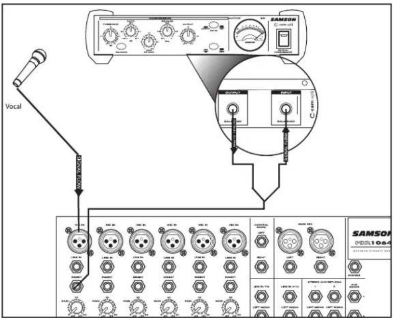
To further control your signal, channels 1-6 on the MDR1064 feature an insertion point, or "effects loop", on one 1/4-inch phone jack, INSERT SEND and RETURN. An insertion point is a patch-point that interrupts the signal,
allowing you to bring that signal outside to be processed by another device. You can use these connections to interface an external signal processor like an equalizer, compressor, noise gate, reverb and other audio devices. A common application for the MDR1064's insert point is using a compressor.
To send a signal to an external processor, use a standard 1/4-inch "Y" insert cable to connect the MDR1064 channel insert point. Connect the TRS (TIP / RING / SLEEVE) plug to the channel INSERT point, and then, connect the 1/4-inch (TIP / SLEEVE), INSERT SEND plug to the input of the external processor. The signal is sent back to the MDR1064, using the 1/4-inch (TIP / SLEEVE), INSERT RETURN plug connecting to the output of the external processor.
The diagram below shows a typical application for using a compressor (in this example a Samson C com opti) in the MDR1064's insertion point. Also below, is a diagram showing the wire for the TRS 'Y' Insert cable.

Operating the MDR1064
USING AN EXTERNAL EFFECT
If you prefer to use an external device for effects processing, you can easily connect the unit using the MDR1064 AUX 2 bus. Follow the simple steps below to interface your processor:
- Connect the AUX 2 OUTPUT to the input of the external effect processor.
- Connect the outputs of the effect processor to the AUX 2 RETURN located on the MDR1064's master section.
- Set the MAIN LEVEL control to the "5" position.
- Raise the AUX 2 knobs for the channels to which you want the external effect to be applied.
- Set the input level of the external effect so that the sound is not distorted and so that the effect's input meter does not indicate a clipped signal.

- Use the AUX RETURN 2 control to adjust the level of the effects processed by the external effects device.
The MDR1064 has a dedicated input for playing back a stereo device such as a CD, Tape or Mini Disk. Below is a description of how you can play back a CD, Tape or MD using the MDR1064's 2 TRACK INPUT.
- Turn the MAIN level control all the way down.
- Press the 2TK TO MIX button down.
- Adjust the MAIN LEVEL control in the master section to the "5" position.
- Start playback on the CD, Tape or MD player, and use the MAIN LEVEL control to set the desired level.
You can record the audio from the MDR1064's mixer section including the MIC, LINE, 2T IN and AUX inputs to a Cassette deck, MD, DAT or any other type of recorder using the 2T OUT outputs. Simply connect the MDR1064's 2 TRACK OUT to the input jacks of the recorder as shown in the diagram on the right and follow the steps below.

- Adjust the MAIN LEVEL control in the master section to the "5" position.
- Set a clean signal using the recorder's input level controls and meters.
- Press RECORD.
- Play back using as described in the previous section "PLAYING BACK A CD USING 2T TO MIX".
MDR1064 System Set-Ups
MDR1064 LIVE SOUND SET-UP

flowchart
graph TD
    A["POWERED SPEAKER INPUT"] --> B["Vocal"]
    A --> C["Vocal"]
    A --> D["Rhythm Guitar"]
    A --> E["Bass Guitar"]
    A --> F["Lead Guitar"]
    A --> G["Signal Processor"]
    A --> H["Direct Box"]
    A --> I["Signal Processor"]
    A --> J["Stereo Signal"]
    K["LEFT MAIN OUTPUT"] --> L["Keyboards"]
    K --> M["SAMSON 1064"]
    N["POWERED SPEAKER INPUT"] --> O["AUX 2 OUTPUT"]
    N --> P["MONITOR AMP OUTPUTS"]
    Q["RIGHT MAIN OUTPUT"] --> R["MDR1064's AUX SEND 1 connected to an external monitor amp."]
    style A fill:#f9f,stroke:#333
    style K fill:#ccf,stroke:#333
    style N fill:#cfc,stroke:#333
    style Q fill:#fcc,stroke:#333
MDR1064 System Set-Ups
MDR1064 RECORDING SET-UP

flowchart
graph TD
    A["Left POWERED MONITOR INPUT"] --> B["Vocal"]
    A --> C["Rhythm Guitar"]
    A --> D["Bass Guitar"]
    A --> E["Lead Guitar"]
    A --> F["Signal Processor"]
    A --> G["Direct Box"]
    A --> H["Signal Processor"]
    A --> I["Stereo Signal"]
    J["Right POWERED MONITOR INPUT"] --> K["RIGHT CONTROL ROOM OUTPUT"]
    K --> L["Samson S· phone Headphone amplifier"]
    L --> M["SAMSON"]
    M --> N["SIGNAL FLOW"]
    N --> O["Keyboards"]
    O --> P["Radio Station"]
    style A fill:#f9f,stroke:#333
    style J fill:#ccf,stroke:#333
    style K fill:#cfc,stroke:#333
    style L fill:#fcc,stroke:#333
    style M fill:#cff,stroke:#333
    style N fill:#ffc,stroke:#333
    style O fill:#cfc,stroke:#333
    style P fill:#fcc,stroke:#333
MDR1064 Wiring Guide
CONNECTING THE MDR1064
The are several ways to interface the MDR1064 to support a variety of applications. The MDR1064 features balanced inputs and outputs, so connecting balanced and unbalanced signals is possible.
Unbalanced 1/4" Connector

Balanced TRS 1/4" Connector

XLR Balanced Wiring Guide


1/4-inch TRS "Y" Insert Cable Wiring Guide

MDR1064 Specifications
Mono input channels
Microphone input electronically balanced, discrete input con-
figuration
Frequency response 10Hz to 45kHz
Distortion (THD & N) 0.005% at 4dBu, 1kHz
Gain range 0dB to +40dB (MIC)
SNR (Signal to Noise Ratio) 105dB
Line input electronically balanced
Frequency response 10Hz to 45kHz
Distortion (THD & N) 0.005% at 4dBu, 1kHz +
Sensitivity range -10dBu to +30dBu
Stereo input Channels
Line input Balanced
Frequency response 10Hz to 45kHz
Distortion (THD & N) 0.005% at +4dBu, 1kHz
Impedances
Microphone input 4.5k Ohm
Channel Insert return 2.5k Ohm
All other inputs 14.8k Ohm or greater
Tape out 1k Ohm
All other output 120 Ohm
Equalization
Hi shelving +/- 15dB @12kHz
Mid bell +/- 15dB @2.5kHz
Low shelving +/- 15dB @80Hz
Low Cut filter 75Hz, 18dB/oct.
Main Mix Section
Noise (Bus noise)
Levels full down: -100dB (ref.: +4dBu)
Level set to 0 dB: 90dBr (ref.: +4dBu)
+22dBu balanced XLR,
22dBu unbalanced, 1/4" jacks
∞ to +15dB
+22dBu
15W
Power supply (AC/AC Adaptor)
Main voltage
USA/Canada 108 - 132V, 60Hz
Europe 210 - 230V, 50Hz
U.K./Australia 240V, 50Hz
Physical
Net weight
6.8 lb. (3.1Kg)
Shipping weight
8.8 lb. (4.0Kg)
Dimension (W D H)
12.2" x 12.5" x 2.8" (310mm x 318mm x
70mm)
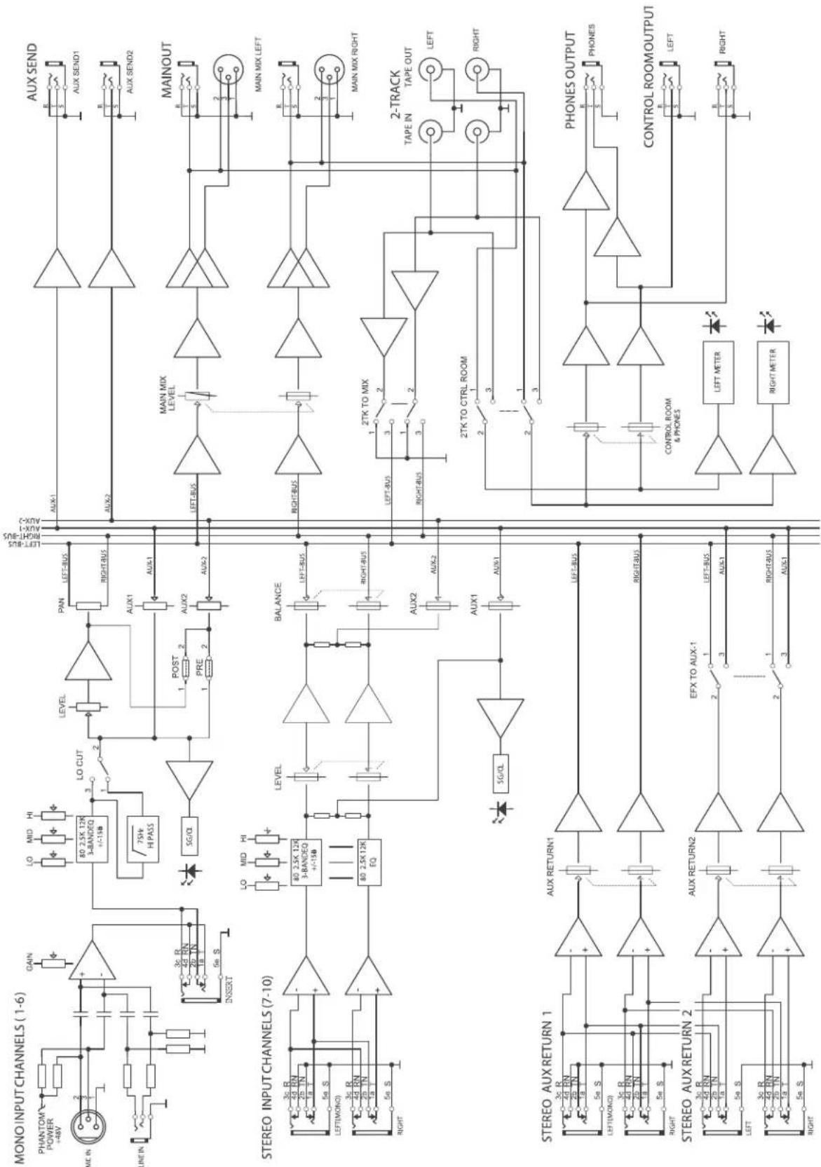
MDR1064 Block Diagram
flowchart
graph TD
    subgraph_MONO_INPUT_CHANNELS["MONO INPUT CHANNELS (1-6)"]
        A["PHANTOM POWER +48V"] --> B["+"]
        C["ME IN"] --> D["2"]
        E["LINE IN"] --> F["3c R, 4d RN, 29 TIN, 1a"] --> G["INSERT"]
        H["LO"] --> I["LO 2.5K 12R 3-BANDEQ +/-15B"]
        J["HI"] --> K["75kV Hi PASS"]
        L["LO CUT"] --> M["LEVEL"]
        N["AUX1"] --> O["AUX2"]
        P["POST"] --> Q["AUX2"]
        R["PRE"] --> S["AUX2"]
        T["AUX1"] --> U["AUX2"]
        V["AUX1"] --> W["AUX2"]
        X["AUX1"] --> Y["AUX2"]
        Z["AUX1"] --> AA["AUX2"]
        AB["AUX1"] --> AC["AUX2"]
    end

    subgraph_STEREO_INPUT_CHANNELS["STEREO INPUT CHANNELS (7-10)"]
        AD["3c R, 4d RN, 29 TIN, 1a"] --> AE["+"]
        AF["LEFT(MONO)"] --> AG["3c R, 4d RN, 29 TIN, 1a"] --> AH["+"]
        AI["RIGHT"] --> AJ["5e S"]
        AK["LEVI"] --> AL["80 2.5K 12R 3-BANDEQ +/-15B"]
        AM["LEVEL"] --> AN["LEVEL"]
        AO["BALANCE"] --> AP["LEFT-BUS"]
        AQ["AUX2"] --> AR["AUX2"]
        AS["AUX1"] --> AT["AUX2"]
        AU["X/AUX1"] --> AV["AUX2"]
        AW["X/AUX2"] --> AX["AUX2"]
    end

    subgraph_STEREO_AUX_RETURN["STEREO AUX RETURN 1"]
        AY["3c R, 4d RN, 29 TIN, 1a"] --> AZ["+"]
        BA["LEFT(MONO)"] --> BB["3c R, 4d RN, 29 TIN, 1a"] --> BC["+"]
        BD["RIGHT"] --> BE["5e S"]
        BF["AUX RETURN1"] --> BG["+"]
        BH["LEFT-BUS"] --> BI["LEFT-BUS"]
        BJ["RIGHT-BUS"] --> BK["RIGHT-BUS"]
    end

    subgraph_STEREO_AUX_RETURN["STEREO AUX RETURN 2"]
        BL["3c R, 4d RN, 29 TIN, 1a"] --> BM["+"]
        BN["LEFT"] --> BO["3c R, 4d RN, 29 TIN, 1a"] --> BO
        BP["AUX RETURN2"] --> BQ["+"]
        BR["EFX TO AUX-1"] --> BS["2"]
        BT["LEFT-BUS"] --> BU["3"]
        BV["AUX1"] --> BW["AUX2"]
        BX["AUX2"] --> BY["AUX2"]
    end

    subgraph MAINOUT
        CA["AUX SEND"] --> CB["AUX SEND1"]
        CD["AUX SEND2"] --> CE["AUX SEND1"]
        CF["MAIN MIX LEVEL"] --> CG["MAIN MIX LEFT"]
        CH["RANK"] --> CI["RANK"]
        CJ["MAIN MIX RIGHT"] --> CK["MAIN MIX LEFT"]
    end

    subgraph 2-TRACK
        CL["TAPE IN TAPE OUT LEFT"] --> CD
        DD["TAPE OUT RIGHT"] --> CE
    end

    subgraph CONTROL ROOM_OUTPUT
        DE["CONTROL ROOM & PHONES"] --> DE
        DE --> DE
        DE --> DE
        DE --> DE
        DE --> DE
        DE --> DE
        DE --> DE
        DE --> DE
    end

    subgraph PHONES_OUTPUT
        DE1["PHONES OUTPUT"] --> DE
        DE2["PHONES OUTPUT"] --> DE
        DE3["PHONES OUTPUT"] --> DE
        DE4["PHONES OUTPUT"] --> DE
        DE5["PHONES OUTPUT"] --> DE
    end

    subgraph CONTROL ROOM_OUTPUT
        DE5["CONTROL ROOM OUTPUT"] --> DE
        DE6["CONTROL ROOM OUTPUT"] --> DE
        DE7["CONTROL ROOM OUTPUT"] --> DE
    end
Notes
Samson Technologies Corp.
575 Underhill Blvd.
P.O. Box 9031
Syosset, NY 11791-9031
Phone: 1-800-3-SAMSON (1-800-372-6766)
Fax: 516-364-3888
www.samsontech.com

- MDR1064 Maximum Dynamic Range
- Owners Manual
- Safety Instructions/Consignes de sécurité/Sicherheitsvorkehrungen/Instrucciones de seguridad
- WARNING
- AVIS
- CAUTION
- ATTENTION
- Important Safety Instructions
- Introduction
- MDR1064 Features
- Front and Rear Panel Controls
- FRONT PANEL
- REAR PANEL
- Controls and Functions
- MONO/STEREO INPUT CHANNEL SECTION
- GAIN
- LOW CUT FILTER
- CHANNEL EQUALIZER
- AUX 1
- AUX 2
- (MONO/STEREO INPUT CHANNEL CONTINUED)
- BALANCE (Stereo Inputs Only)
- PAN (Mono Inputs Only)
- PEAK LED
- CHANNEL LEVEL
- MASTER SECTION
- MAIN LEVEL
- PHONES / CR
- TRACK INPUT AND OUTPUT
- 2TK TO CR
- 2TK TO MIX
- Auxiliary Returns
- AUX RET 1
- MASTER SECTION (continued)
- AUX RET 2
- TO AUX 1
- POWER LED
- Phantom Power LED
- Output Level Meter
- MDR1064 Input and Output Connections
- CHANNEL 1 - 6 MIC and LINE INPUTS
- Microphone Input - Mono Input Channels
- Line Level Input - Mono Input Channels
- Insert Point Jack - Mono Input Channels
- Line Level Input - Stereo Input Channels
- MASTER SECTION INPUT AND OUTPUT JACKS
- CONTROL ROOM LEFT/RIGHT OUTPUT
- HEADPHONE OUTPUT
- AUX Send 1
- AUX Send 2
- AUX RETURN 2 LEFT/RIGHT
- AUX RETURN 1 LEFT/RIGHT
- 2TR INPUT
- 2TR OUTPUT
- Operating the MDR1064
- BASIC OPERATION
- CONNECTING MICROPHONES AND INSTRUMENTS
- SENDING AN INDEPENDENT MIX TO THE MONITOR SPEAKERS
- USING THE CHANNEL INSERT JACKS
- USING AN EXTERNAL EFFECT
- MDR1064 System Set-Ups
- MDR1064 RECORDING SET-UP
- MDR1064 Wiring Guide
- CONNECTING THE MDR1064
- Unbalanced 1/4" Connector
- Balanced TRS 1/4" Connector
- XLR Balanced Wiring Guide
- 1/4-inch TRS "Y" Insert Cable Wiring Guide
- MDR1064 Specifications
- Mono input channels
- Stereo input Channels
- Impedances
- Equalization
- Main Mix Section
- Power supply (AC/AC Adaptor)
- Physical
- Notes
Brand : SAMSON
Model : MDR1064
Category : Mixer