
SSD 64 GB - SSD SANDISK - Free user manual and instructions
Find the device manual for free SSD 64 GB SANDISK in PDF.


| Product Type | Solid State Drive (SSD) |
| Brand | SanDisk |
| Model | SSD 64 GB |
| Storage Capacity | 64 GB |
| Form Factor | 2.5 inch (thickness 7 mm) |
| Interface | SATA III (6 Gb/s) |
| Sequential Read Speed | Up to 520 MB/s |
| Sequential Write Speed | Up to 350 MB/s |
| NAND Flash Type | 3D NAND |
| Dimensions (L x W x H) | 100 x 69.85 x 7 mm |
| Weight | Approximately 57 g |
| Power Consumption (Active) | 0.5 W typical |
| Power Consumption (Idle) | 0.3 W typical |
| Operating Temperature | 0 °C to 70 °C |
| Storage Temperature | -55 °C to 95 °C |
| Shock Resistance | 1500 G (0.5 ms) |
| MTBF | 1,500,000 hours |
| Endurance (TBW) | 36 TB |
| Warranty | 3 years limited |
| Key Features | Silent, shock-resistant, low power consumption |
| Maintenance and Cleaning | No regular maintenance needed. Avoid physical shocks, keep dry, and do not disassemble. |
| Safety | Handle with care to avoid ESD. Do not expose to liquids or high temperatures. |
| Spare Parts and Repairability | No user-serviceable parts. Contact support for warranty replacement. |
Frequently Asked Questions - SSD 64 GB SANDISK
User questions about SSD 64 GB SANDISK
0 question about this device. Answer the ones you know or ask your own.
Ask a new question about this device
Download the instructions for your SSD in PDF format for free! Find your manual SSD 64 GB - SANDISK and take your electronic device back in hand. On this page are published all the documents necessary for the use of your device. SSD 64 GB by SANDISK.
USER MANUAL SSD 64 GB SANDISK
The content of this document is condenal & subject to change without noce
Document No. 80-11-XXXXX
SanDisk Corporaon
Corporate Headquarters • 601 McCarthy Blvd. • Milpitas, CA 95035
Phone (408) 801-1000 • Fax (408) 801-8657
www.sandisk.com
SanDisk Corporaon general policy does not recommend the use of its products in life support applicaons wherein a failure or malfuncon of the product may directly threaten life or injury. Without limitaon to the foregoing, SanDisk shall not be liable for any loss, injury or damage caused by use of its products in any of the following applicaons:
Special applications such as military related equipment, nuclear reactor control, and aerospace Control devices for automove vehicles, train, ship and trac equipment Safety system for disaster prevenon and crime prevenon
Medical-related equipment including medical measurement device
Accordingly, in any use of SanDisk products in life support systems or other applicaons where failure could cause damage, injury or loss of life, the products should only be incorporated in systems designed with appropriate redundancy, fault tolerant or back-up features. Per SanDisk Terms and Conditions of Sale, the user of SanDisk products in life support or other such applicaons assumes all risk of such use and agrees to indemnify, defend and hold harmless SanDisk Corporaon and its aliases against all damages.
Security safeguards, by their nature, are capable of circumvenon. SanDisk cannot, and does not, guarantee that data will not be accessed by unauthorized persons, and SanDisk disclaims any warranties to that eect to the fullest extent permied by law.
This document and related material is for informaon use only and is subject to change without prior noce. SanDisk Corporaon assumes no responsibility for any errors that may appear in this document or related material, nor for any damages or claims resulting from the furnishing, performance or use of this document or related material. Absent a wrien agreement signed by SanDisk Corporaon or its authorized representave to the contrary, SanDisk Corporaon explicitly disclaims any express and implied warranties and indemnies of any kind that may or could be associated with this document and related material, and any user of this document or related material agrees to such disclaimer as a precondition to receipt and usage hereof. EACH USER OF THIS DOCUMENT EXPRESSLY WAIVES ALL GUARANTIES AND WARRANTIES OF ANY KIND ASSOCIATED WITH THIS DOCUMENT AND/OR RELATED MATERIALS, WHETHER EXPRESS OR IMPLIED, INCLUDING WITHOUT LIMITATION, ANY IMPLIED WARRANTY OF MERCHANTABILITY OR FITNESS FOR A PARTICULAR PURPOSE OR INFRINGEMENT, TOGETHER WITH ANY LIABILITY OF SANDISK CORPORATION AND ITS AFFILIATES UNDER ANY CONTRACT, NEGLIGENCE, STRICT LIABILITY OR OTHER LEGAL OR EQUITABLE THEORY FOR LOSS OF USE, REVENUE, OR PROFIT OR OTHER INCIDENTAL, PUNITIVE, INDIRECT, SPECIAL OR CONSEQUENTIAL DAMAGES, INCLUDING WITHOUT LIMITATION PHYSICAL INJURY OR DEATH, PROPERTY DAMAGE, LOST DATA, OR COSTS OF PROCUREMENT OF SUBSTITUTE GOODS, TECHNOLOGY OR SERVICES.
No part of this document may be reproduced, transmied, transcribed, stored in a retrievable manner or translated into any language or computer language, in any form or by any means, electronic, mechanical, magnec, opcal, chemical, manual or otherwise, without the prior written consent of an ocer of SanDisk Corporaon.
All parts of the SanDisk documentaon are protected by copyright law and all rights are reserved. SanDisk and the SanDisk logo are registered trademarks of SanDisk Corporaon, registered in the United States and other countries. Other brand names menoned herein are for idencaon purposes only and may be the trademarks of their respective holder(s).
© 2011 SanDisk Corporaon. All rights reserved.
Document No. 80-11-XXXXX
08/2011 Printed in U.S.A.
Revision History
| Revision | Descripon | Date |
| 0.90 | Fix 32GB sequenal write (SATA-II) value.Update power consumpon numbers with nal product conguraon.Add product weight for each form-factor.Changed Idenfy Data Word 235 to indicate maximum # of sectors per ‘segmented’ Download Microcode is 16 (10h).Changed DEVSLP -> DEVSLPChange Power class levelsUpdated footnotesRemoved Random Burst (Recovered) Write performance metric | August 25, 2011 |
Table of Contents
1. INTRODUCTION 8
1.1 GENERAL DESCRIPTION....8
1.2 KEY FEATURES 10
1.3 FUNCTIONAL DESCRIPTION.... 12
1.4 ADVANCED FLASH MANAGEMENT 13
1.4.1 Non-Volale Write Cache 13
1.4.2 Defect and Error Management 14
1.4.3 Wear Leveling 14
1.4.4 Bad Block Management.... 14
1.5 ADVANCED LOW POWER MANAGEMENT 15
1.5.1 Slumber SATA low power mode 15
1.5.2 DEVLSP SATA low power mode 15
1.6 BACKGROUND GARBAGE COLLECTION 15
1.7 POWER CLASSES....16
1.8 PERFORMANCE THROTTLING.... 16
2. GENERAL PRODUCT SPECIFICATIONS .... 17
2.1 INTERFACE 17
2.2 CAPACITY....17
2.3 PERFORMANCE 18
2.3.1 Mul-level cell (MLC) Performance.... 18
2.4 ENDURANCE 19
2.4.1 Mul-level cell (MLC) Endurance 19
3. POWER CHARACTERISTICS....20
3.1 SUPPLY VOLTAGE 20
3.2 GRACEFUL POWER-OFF REQUIREMENTS 20
3.3 AVERAGE POWER CONSUMPTION....21
3.3.1 Mul-level cell (MLC) Average Power Consumpon 21
3.4 ACTIVE POWER CONSUMPTION 22
3.4.1 Mul-level cell (MLC) Acve Power Consumpon 22
3.5 LOW POWER MODE CONSUMPTION 23
3.5.1 Low Power Mode Consumpon 23
4. PHYSICAL SPECIFICATION 24
4.1 HALF-SLIM SATA FORM FACTOR 24
4.1.1 Standard SATA 8GB-64GB capacity 24
4.1.2 Half-Slim SATA 128GB-256GB capacity 25
4.2 MSATA FORM FACTOR 26
4.2.1 mSATA 8GB-64GB capacity.... 26
4.2.2 mSATA 128GB-256GB capacity.... 27
4.3 MSATA MINI FORM FACTOR 28
4.3.1 mSATA Mini 8GB capacity 28
4.3.2 mSATA Mini 16GB-128GB capacity.... 28
5. ENVIRONMENTAL SPECIFICATIONS....29
5.1 TEMPERATURE....29
5.2 HUMIDITY 29
5.3 VIBRATION....29
5.4 SHOCK....29
5.5 ALTITUDE....29
5.6 ELECTROSTATIC DISCHARGE (ESD) 30
5.7 ACOUSTICS....30
5.8 EMI/RFI COMPLIANCE 30
5.9 RoHS 30
5.10 REGULATIONS....31
6. RELIABILITY CHARACTERISTICS.... 32
6.1 ERROR RATE....32
6.2 MTTF (MEAN-TIME-TO-FAILURE) 32
7. INTERFACE 33
7.1 SUPPORTED STANDARDS....33
7.2 PIN ASSIGNMENTS – HALF-SLIM SATA CONNECTOR.... 33
7.3 PIN ASSIGNMENTS – MSATA 34
8. SUPPORTED ATA COMMANDS 35
8.1 IDENTIFY DATA 39
8.2 LOG PAGES 43
9. ORDERING INFORMATION 44
9.1 SANDISK SSD U100 MLC PRODUCTS ORDERING INFORMATION 44
10. CONTACT INFORMATION 45
Table of Figures
FIGURE 1-1: SANDISK SSD U100 BLOCK DIAGRAM 8
FIGURE 1-2: SANDISK SSD U100 NCACHE™ TECHNOLOGY.... 13
FIGURE 4-1 : HALF-SLIM SATA 8-64GB TOP VIEW .... 24
FIGURE 4-2 : HALF-SLIM SATA 8-64GB SIDE VIEW.... 24
FIGURE 4-3 : MSATA 8-64GB TOP VIEW 26
FIGURE 4-4 : MSATA 8-64GB SIDE VIEW....26
FIGURE 4-5 : MSATA 128-256GB TOP VIEW 27
FIGURE 4-6 : MSATA 128-256GB SIDE VIEW....27
FIGURE 4-7 : MSATA MINI 16-128GB TOP VIEW ...... 28
FIGURE 4-8 : MSATA MINI 16-128GB SIDE VIEW 28
Table of Tables
TABLE 1-1: SANDISK SSD U100 POWER CLASSES.... 16
TABLE 2-1: SANDISK SSD U100 CAPACITY SPECIFICATION ...... 17
TABLE 2-2: SANDISK SSD U100 (MLC) PERFORMANCE 18
TABLE 2-3: SANDISK SSD U100 (MLC) ENDURANCE.... 19
TABLE 3-1: SANDISK SSD U100 SUPPLY VOLTAGE....20
TABLE 3-2: SANDISK SSD U100 (MLC) AVERAGE POWER CONSUMPTION ...... 21
TABLE 3-3: SANDISK SSD U100 (MLC) ACTIVE POWER CONSUMPTION....22
TABLE 3-4: SANDISK SSD U100 POWER CONSUMPTION IN LOW POWER MODE....23
TABLE 4-1: MECHANICAL INFORMATION – HALF-SLIM SATA FORM FACTOR 24
TABLE 4-2: MECHANICAL INFORMATION - MSATA FORM FACTOR.... 26
TABLE 4-3: MECHANICAL INFORMATION - MSATA MINI FORM FACTOR 28
TABLE 5-1: SANDISK SSD U100 TEMPERATURE SPECIFICATION ...... 29
TABLE 5-2: SANDISK SSD U100 HUMIDITY SPECIFICATION ...... 29
TABLE 5-3: SANDISK SSD U100 VIBRATION SPECIFICATION ...... 29
TABLE 5-4: SANDISK SSD U100 SHOCK SPECIFICATION....29
TABLE 5-5: SANDISK SSD U100 ALTITUDE SPECIFICATION 29
TABLE 5-6: SANDISK SSD U100 ESD SPECIFICATION 30
TABLE 5-7: SANDISK SSD U100 EMI/RFI COMPLIANCE 30
TABLE 5-8: SANDISK SSD U100 REGULATION STANDARDS ...... 31
TABLE 6-1: SANDISK SSD U100 MTTF....32
TABLE 7-1: STANDARD SATA CONNECTOR PIN ASSIGNMENT ...... 33
TABLE 7-2: MSATA CONNECTOR PIN ASSIGNMENT....34
TABLE 8-1: SUPPORTED ATA COMMANDS.... 38
TABLE 8-2: IDENTIFY DATA VALUES 42
TABLE 8-3: SUPPORTED SMART LOG PAGES 43
TABLE 9-1: SSD U100 MLC ORDERING INFORMATION 44
TABLE 9-2: EXAMPLES OF DECODED SKU FOR SSD U100 MLC PRODUCTS 44
1. Introduction
1.1 General Description
The SanDisk® SSD U100 builds on the momentum of three generaons of SSD P-Series and the overall trend in the market towards smaller, thinner compung machines that enable mobility, connectivity on the go and instant-on capability.
Designed and built on the philosophy of providing improved user-experience at aordable cost, SanDisk SSD U100 is a perfect replacement for HDD in the consumer market. The SanDisk SSD U100 beats HDD in every possible metric – size, weight, shock and vibraon tolerance, power consumption, sequential and random read performances as well as sequential and random write performances.
The SanDisk SSD U100 houses a powerful SATA SSD controller that is fully compliant to SATA 6Gb/s (Revision 3.0) standards on the front-end. Matching the speed on the back-end side, the SSD controller is designed with 4 high-speed NAND Flash channels each operang at a maximum speed of 194MB/s. This allows the product to achieve superior performance up to 450MB/s and 350MB/s for sequential read and sequential write, respectively. It fullls the market's ever increasing demand of seamless user-experience, improved mul-tasking capabilities and extreme responsiveness. The SATA interface aligns with the global transition in the industry, which is enforced by the plaorm's chipsets.
Using the advanced 24nm memory geometry provides for a low-cost product which beats the HDD's price in the capacity ranges of 8GB-32GB and provides a very compeve product at capacities ranging 64GB to 256GB. The SanDisk SSD U100 is oered in many small form factors, allowing SanDisk to maintain its leadership in this market. The small form factor enables further miniaturizaon of Netbook, SmartBook and Tablet designs and opens doors for a whole range of other applicaons such as Ultrabooks (Ultrathin Notebooks).
![graph LR A["SATA-III I/F (6Gbps)"] --> B["NAND Flash SSD Controller"] B --> C["8-bit Toggle Mode"] --> D["NAND Flash Array - 0"] B --> E["8-bit Toggle Mode"] --> F["NAND Flash Array - 1"] B --> G["8-bit Toggle Mode"] --> H["NAND Flash Array - 2"] B --> I["8-bit Toggle Mode"] --> J["NAND Flash Array…](/content/2026/06/1253222/images/d561982998c851958dda4e80f9b9d92ce3f8f3ba029b177f54f2aca059d32c3f.jpg)
Figure 1-1: SanDisk SSD U100 Block Diagram
The SanDisk SSD U100 employs a low power architecture that significantly reduces the power consumed by the device in low power modes - allowing the users' to extend the charge cycles of the baery – highly-desired by mobility applicaons.
Built on the fundamentals of solid state technology, the SSD U100 has no moving parts, unlike an HDD, significantly improving the mechanical reliability of the device. The advanced ash management technology designed into the device rmware allows the SSD U100 to achieve superior sequential and random IO performance, and improves long-term data endurance (measure of device reliability) significantly. The device rmware also implements funcons of Dynamic bad block management, dynamic and stac wear-leveling, and robust error detecon and correcon code (EDC/ECC) to ensure data integrity. Once the SSD has been congured by the host, it appears to the host as a standard SATA disk drive.
1.2 Key Features
- High-capacity, ultra-small form factor supporting unformed capacities 1 of 8GB, 16GB, 32GB, 64GB, 128GB and 256GB 2 :
- Half-Slim SATA 2.5" standard connector, complies to JEDEC-297 standard
- Standard mSATA form factor with a Mini-PCIe edge connector, complies to JEDEC MO-300A standard
- mSATA Mini form factor with a Mini-PCIe edge connector, complies to JEDEC MO-300B standard
■ Interface to host:
■ SATA 6Gb/s (Revision 3.0) compliant
■ Backwards compliant to SATA 3Gb/s & SATA 1.5Gb/s
■ ATA Command Set ACS-2
■ NCQ support up to queue depth = 32
■ High performance 3 :
■ Maximum Host transfer rate: 6Gb/s
■ Sustained Sequenal Read: 450 MB/s
■ Sustained Sequenal Write: 350 MB/s
■ 4K Random Write (Sustained): 630 IOPS
■ 4K Random Read: 9400 IOPS
■ Low power consumpon:
■ Typical read/write 4 : 45mW
■ Slumber power mode 5 : 10mW
■ DEVSLP power mode 6 : TBD
■ Advanced Flash Management:
- nCache™ – Non Volale Write Cache
■ Support for TRIM
■ Dynamic & Stac Wear-leveling
■ Bad Block Management
■ Background Garbage Collecon
■ Support for Performance throling and Power Classes:
■ Performance will be throled in the event juncon temperature of critical components is measured to be exceeding the maximum allowable for the product.
- A Power Class feature is supported to allow the Host to denote the maximum allowable power consumed by the device - honoring a power budget of the host.
■ Ungraceful power loss handling:
■ Implements special hardware to detect the event of ungraceful power loss.
■ Ensures integrity of the data residing on the SSD 7 .
- Highly-reliable:
- Mean me to failure (MTTF) – refer to Secon 6.2 for capacity-specific values
■ Operang shock: 1,500G, 0.5msec half sine
■ Operang vibraon: 5gRMS, 10-2000 Hz
■ Operang temperature: 0°C to 70°C
■ Non-operang temperature and storage: -55°C to +85°C
1.3 Functional Description
The SSD U100 contains a high-level, intelligent storage subsystem. This intelligent (microcontroller) subsystem provides many capabilities not found in other types of memory devices.
These capabilities include the following:
■ Compliant to SATA 6Gb/s (Revision 3.0) standard
■ Supports ATA register and command set (ATA-8 / ACS2 standard)
■ Support for NCQ, up to queue depth = 32
■ Support for Trim command
■ S.M.A.R.T. feature supported
■ Advanced power management
■ Implementaon of dynamic and stac wear-leveling to extend
■ Sophiscated system for error recovery including a powerful error correcon code (ECC)
■ Host independence from details of erasing and programming ash memory
- Sophiscated system for managing defects (similar to systems found in magnec disk drives)
1.4 Advanced Flash Management
1.4.1 Non-Volatile Write Cache
The fourth genera on of modular SSD, the SSD U100 supports a unique feature to improve burst and sustained random write performance and ensure very positive user experience. Studies show that modern (client as well as mobile) operang systems (like Windows7, Windows Mobile, Android, ChromeOS) mostly access the storage device using small access blocks, with the majority being 4KB access blocks.
![graph LR A["SATA-III Host Controller"] --> B["SATA-III Device Controller"] B --> C["nCache Page Based"] B --> D["nCache Page Based"] B --> E["nCache Page Based"] B --> F["nCache Page Based"] C <--> G["MLC NAND Flash Chunk Based"] D <--> H["MLC NAND Flash Chunk Based"] E <--> I["MLC NAND Flash Chunk…](/content/2026/06/1253222/images/d33d12b50e322d5ee0d5765118047b876abc8aa123452ce6463059a532ddb5d7.jpg)
Figure 1-2: SanDisk SSD U100 nCache™ technology
These small logical access blocks conict with the physical NAND block structure (>=2MB) for the newer genera on ash memory technology. Therefore, to bridge this dience, the SSD U100 employs a non-volale NAND Flash write cache called the nCache™. The nCache™ is used to accumulate these small writes (called cache segments) at high-speed and then ush and consolidate them to a larger MLC secon of the NAND Flash memory in the background during idle me.
The cache size of the SSD U100 is over 500MB - an order of magnitude larger than other compeng soluons that use DRAM based cache. Due to its large size, for most of the daily user acvity, the nCache™ never overows and the user experiences high-burst performance rather than the sustained performance. Once the nCache™ becomes full, the performance of SSD U100 drops to the steady state condion.
1.4.2 Defect and Error Management
SSD U100 contains a sophisticated defect and error management system that is similar to the systems found in magnec disk drives, and in many cases, oers enhancements. If necessary, the SSD device will rewrite data from a defective block to a good block. This acon is completely transparent to the host and does not consume any user data space.
The SSD so error rate specicaon is much beer than the magnec disk drive specicaon. In the extremely rare case that a read error does occur, the SSD U100 products have innovate algorithms to recover the data by using error detecon code and error correcon code (EDC/ECC). These defect and error management systems, coupled with the solid state construcon, give SSD U100 unparalleled reliability.
1.4.3 Wear Leveling
Wear leveling is an intrinsic part of the erase pooling funconality of SSDs using NAND memory. Advanced features of dynamic and stac wear-leveling, and automac block management are used to ensure an even distribution of write/erase cycles throughout the enre device, regardless of how dynamic or stac the data wrien is. This guarantees high data reliability and maximizes ash life expectancy.
1.4.4 Bad Block Management
Bad blocks are occasionally created during the life cycle of a ash component, in a phenomenon called dynamic bad-block accumulation. These bad blocks must be marked and replaced dynamically in order to prevent read/write failures. When a bad block is detected, the embedded Bad Block Mapping algorithm maps out the block, which will remove the block from future use.
1.5 Advanced Low Power Management
The SanDisk SSD U100 employs advanced low power architecture that reduces power consumption in low power modes. In particular, the SSD U100 supports the following SATA low power modes:
1.5.1 Slumber SATA low power mode
The SanDisk SSD U100 supports entering into Slumber SATA low power mode through DIPM (Device Initiated Power Management) as well as HIPM (Host Initiated Power Management). Upon compleon of any command, in case of DIPM, the SSD will request the host to enter into Slumber power if there is no SATA bus acvity for 20msec.
1.5.2 DEVLSP SATA low power mode
The SSD U100 employs the newest DEVSLP SATA low power mode that further reduces device power consumption in the IDLE state - thereby extending the me between charging of a baery, which is highly-desired in mobility applications. The standard SATA low power modes, Paral and Slumber, need SATA OOB (Out of Band) commands to return to normal operation. The SATA PHY has to be parally powered up to respond to the OOB command sequence, resulting in high Slumber mode current. DEVSLP enables the device, and onally the host, to completely shut-o their SATA PHY, resulting in much lower power consumption compared to Slumber SATA low power mode.
1.6 Background Garbage Collection
Once the SATA PHY has entered into Slumber state, the ash management rmware can ulize the me the device is idle in order to perform internal house-keeping operaons. These internal house-keeping advies include freeing up the space in the nCache by ushing and consolidang to the MLC storage. Performing internal house-keeping advies in background will significantly improve burst performance of the device, providing swi user experience and, at the same me, allowing for beer ulizaon of the nCache. These operaons are executed internally, while reporting device status READY to the host. Any me a new command is received from the host the internal operaons will be terminated and the host command will be serviced with minimal delay. If no command is received by the device, the execution of the house-keeping advies will be limited to 30 seconds – designed to maintain low power consumption.
1.7 Power classes
The SanDisk SSD U100 targeted towards convergence market space characterized by stringent power budget originang from the objecve to either extend baery charge cycle or due to power ICs limitaon. In order to allow an adequate power-performance tradeo, the SanDisk SSD U100 supports three power classes as dene in the table below.
The operang Power Class is selected using user congorable or Operang System inputs.
| Power Class | Unit | Power Class I | Power Class II | Power Class III |
| Maximum Active Power consumption | mW | 800 | 1200 | 2000 |
Table 1-1: SanDisk SSD U100 Power Classes
1.8 Performance Throttling
In order to protect the integrity of the data and prevent excessive heat dissipacn, the SSD U100 ulizes an on-board/on-chip thermal sensor to monitor the SSD's crical component juncon temperature. If the temperature rises above the allowable limit, the performance will be reduced until the temperature decreases to an allowable level. This performance throling technique acts as a safety measure as well as a means for achieving power class implementaon described in the previous secon.
2. General Product Specifications
2.1 Interface
The SSD U100 interface complies with the Serial ATA standard published by ANSI. The device complies with the SATA 6Gb/s, Revision 3.0 specicaons and supports ATA Command Set ACS-2.
For more informaon, refer to the American Naonal Standard X3.221: AT Aachment for Interface for Disk Drives document. Documentaon can be ordered from IHS by calling 1-800-854-7179 or accessing their Web site: hp://global.ihs.com
2.2 Capacity
| Unformed Capacity9 | Total Number of User-Addressable Sectors in LBA Mode10 | Number of Logical Cylinders | Number of Logical Heads | Number of Logical Sectors per Track |
| 8GB | 15,649,200 | 15,525 | 16 | 63 |
| 16GB | 31,277,232 | 16,383 | 16 | 63 |
| 32GB | 62,533,296 | 16,383 | 16 | 63 |
| 64GB | 125,045,424 | 65,535 | 16 | 63 |
| 128GB | 250,069,680 | 65,535 | 16 | 63 |
| 256GB | 500,118,192 | 65,535 | 16 | 63 |
Table 2-1: SanDisk SSD U100 Capacity Specicaon
2.3 Performance 11
2.3.1 Multi-level cell (MLC) Performance
| Parameter | Unit | NCQ | 8GB | 16GB | 32GB | 64GB | 128GB | 256GB |
| SATA 3Gb/s host interface | ||||||||
| Sequential Read12 | MB/s | NCQ=1 | 110 | 210 | 210 | 210 | 210 | 210 |
| NCQ=32 | 110 | 220 | 240 | 240 | 240 | 240 | ||
| Sequential\ Write12 | MB/s | NCQ=1 | 25 | 50 | 110 | 190 | 190 | 190 |
| NCQ=32 | 25 | 50 | 110 | 220 | 230 | 230 | ||
| Random Read [4KB] 13 | IOPs | NCQ=1 | 4200 | 4200 | 4200 | 4200 | 4200 | 4200 |
| NCQ=32 | 5000 | 9200 | 9400 | 9400 | 9400 | 9400 | ||
| Random Write - Sustained [4KB] 13 | IOPs | NCQ=1 | 40 | 100 | 190 | 300 | 530 | 600 |
| NCQ=32 | 40 | 100 | 190 | 300 | 530 | 600 | ||
| Typical power-on ready time | msec | 35 typical | 55 typical | 85 typical | 125 typical | 125 typical | 125 typical | |
| Parameter | Unit | 8GB | 16GB | 32GB | 64GB | 128GB | 256GB | |
| SATA 6Gb/s host interface | ||||||||
| Sequential Read12 | MB/s | NCQ=1 | 110 | 220 | 360 | 380 | 380 | 380 |
| NCQ=32 | 110 | 220 | 450 | 450 | 450 | 450 | ||
| Sequential\ Write12 | MB/s | NCQ=1 | 25 | 50 | 110 | 220 | 320 | 320 |
| NCQ=32 | 25 | 50 | 110 | 220 | 350 | 350 | ||
| Random Read [4KB] 13 | IOPs | NCQ=1 | 4200 | 4200 | 4200 | 4200 | 4200 | 4200 |
| NCQ=32 | 5000 | 9200 | 9400 | 9400 | 9400 | 9400 | ||
| NCQ=1 | 40 | 100 | 200 | 300 | 530 | 630 | ||
| Random Write - Sustained [4KB] 13 | IOPs | NCQ=32 | 40 | 100 | 200 | 300 | 530 | 630 |
| NCQ=32 | 40 | 100 | 200 | 300 | 530 | 630 | ||
| Typical power-on ready time | msec | 35 typical | 55 typical | 85 typical | 125 typical | 125 typical | 125 typical | |
Table 2-2: SanDisk SSD U100 (MLC) Performance
2.4 Endurance
2.4.1 Multi-level cell (MLC) Endurance
| Parameter | 8GB | 16GB | 32GB | 64GB | 128GB | 256GB |
| Long Term Data Endurance (LDE) 14 | 5TBW | 10TBW | 20TBW | 40TBW | 80TBW | 160TBW |
Table 2-3: SanDisk SSD U100 (MLC) Endurance
3. Power Characteristics
3.1 Supply Voltage
| Parameter | Specicaons | |
| Input Voltage | Form Factor | |
| Standard SATA connector | 5V ± 5% | |
| mSATA / mSATA Mini | 3.3V ± 5% | |
| Maximum Ripple | 70mV (peak to peak),0 - 30MHz | |
| Supply Rise Time | 7msec to 500msec | |
Table 3-1: SanDisk SSD U100 Supply Voltage
3.2 Graceful Power-off Requirements
By default, most OS's operate with Host Write Cache 'enabled,' which more accurately means there can be data residing in the U100 that hasn't been successfully programmed into ash memory (this is a feature of ATA and not specific to SanDisk SSD products). To ensure this data is properly commied to ash memory, the U100 requires a Flush Cache command followed by a Standby Immediate command prior to power being removed. This command sequence allows the U100 to complete the programming of all data in its volatile data cache into ash memory, returning 'good' status to the host only aer successful compleon. This command sequence is handled transparently by most OS's during a standard shutdown sequence (e.g., hibernaon, shutdown, standby, etc).
However, it is possible that in some applicaons (e.g., embedded systems without a typical user-interface providing graceful power-down opons), power to the U100 could be removed, without warning, precluding the possibility of a graceful shutdown. To assist in the protecon against data loss, the U100 ulizes an internal voltage sensor to detect the loss of power. In combinaon with residual power (i.e., current) from the host, the U100 will use the voltage sensor trigger to stop any outstanding ash programming operaon that may lead to data loss. Please refer to the "Unexpected Power Loss Consideraons" white paper available from SanDisk, which provides specific details relang to this topic.
3.3 Average Power Consumption
Average power consumpon is dened as the blended read/write/idle power used by the SSD U100 while it is operang with a typical OS installed. The power consumpon is being recorded while running MobileMark™ 2007 with Device Initiated Power Management (DIPM) enabled (allowing the SSD U100 to enter low power modes during host idle me). MobileMark™ 2007 simulates the usage of standard user applicaons in the Windows environment, providing a reproducible test plaorm for measuring average power consumpon.
3.3.1 Multi-level cell (MLC) Average Power Consumption
| Input Voltage | Parameter | 8GB | 16GB | 32GB | 64GB | 128GB | 256GB |
| SATA 3Gb/s host interface | |||||||
| 5V ± 5% | Read/Write [mW] | 43 | 43 | 45 | 52 | 55 | 55 |
| 3.3V ± 5% | Read/Write [mW] | 40 | 40 | 42 | 50 | 52 | 52 |
| SATA 6Gb/s host interface | |||||||
| 5V ± 5% | Read/Write [mW] | 45 | 46 | 47 | 52 | 60 | 60 |
| 3.3V ± 5% | Read/Write [mW] | 42 | 43 | 45 | 50 | 54 | 54 |
Table 3-2: SanDisk SSD U100 (MLC) Average Power Consumpon
3.4 Active Power Consumption
Acve power consumpon is measured while the U100 is connuously processing sequential read and write commands (tested separately) with a transfer size of 256 sectors per command (128KB). Measurement of acve power consumpon is meant to demonstrate the worst-case connuous power required by the SSD U100 during long read or write command sequences.
3.4.1 Multi-level cell (MLC) Active Power Consumption
| Input Voltage | Parameter | 8GB | 16GB | 32GB | 64GB | 128GB | 256GB |
| SATA 3Gb/s host interface | |||||||
| 5V ± 5% | Read [mW] | 550 | 770 | 840 | 875 | 950 | 1010 |
| Write [mW] | 550 | 755 | 1090 | 1750 | 1890 | 2025 | |
| 3.3V ± 5% | Read [mW] | 500 | 700 | 775 | 815 | 885 | 955 |
| Write [mW] | 500 | 680 | 1040 | 1710 | 1875 | 1995 | |
| SATA 6Gb/s host interface | |||||||
| 5V ± 5% | Read [mW] | 575 | 795 | 1175 | 1210 | 1300 | 1400 |
| Write [mW] | 575 | 775 | 1110 | 1775 | 2855 | 3040 | |
| 3.3V ± 5% | Read [mW] | 510 | 725 | 1090 | 1145 | 1240 | 1330 |
| Write [mW] | 510 | 700 | 1058 | 1740 | 2815 | 3000 | |
Table 3-3: SanDisk SSD U100 (MLC) Acve Power Consumpon
3.5 Low Power Mode Consumption
Low power mode consumpon is dened as the mode where the SSD U100 has entered Slumber mode (SATA PHY state) and DPDM (SSD U100 specic 'deep power down mode' that is entered aer a period of at least 20ms where no ATA commands are received from the host).
3.5.1 Low Power Mode Consumption
| Input Voltage | Parameter | 8GB | 16GB | 32GB | 64GB | 128GB | 256GB |
| SATA 3Gb/s host interface | |||||||
| 5V ± 5% | Partial / Slumber Mode [mW] | 10.00 | 10.40 | 12.10 | 13.50 | 13.70 | 13.70 |
| 3.3V ± 5% | Partial / Slumber Mode [mW] | 8.00 | 8.02 | 10.20 | 10.43 | 10.60 | 10.60 |
| DEVSLP Power Mode [mW] | TBD | TBD | TBD | TBD | TBD | TBD | |
| SATA 6Gb/s host interface | |||||||
| 5V ± 5% | Partial / Slumber Mode [mW] | 10.20 | 10.45 | 12.15 | 13.70 | 13.75 | 13.75 |
| 3.3V ± 5% | Partial / Slumber Mode [mW] | 8.20 | 8.45 | 10.39 | 10.56 | 10.75 | 10.75 |
| DEVSLP Power Mode [mW] | TBD | TBD | TBD | TBD | TBD | TBD | |
Table 3-4: SanDisk SSD U100 Power Consumpon in Low Power Mode
4. Physical Specification
4.1 Half-Slim SATA Form Factor
Complies with SFF-8156/MO-297 standards
| Parameter | Specifications |
| Width | 54mm |
| Length | 39mm |
| Thickness (max) | 3.08mm (8-64GB), 2.88mm (128-256GB), Connector 4.00mm |
| Typical Weight | 5.9g (8GB), 6.6g (16GB), 7.5g (32-64GB), 7.7g (128-256GB) |
Table 4-1: Mechanical Informaon – Half-Slim SATA form factor
4.1.1 Standard SATA 8GB-64GB capacity
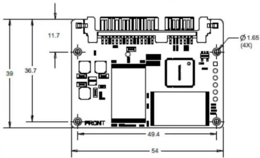
Figure 4-1: Half-Slim SATA 8-64GB Top View
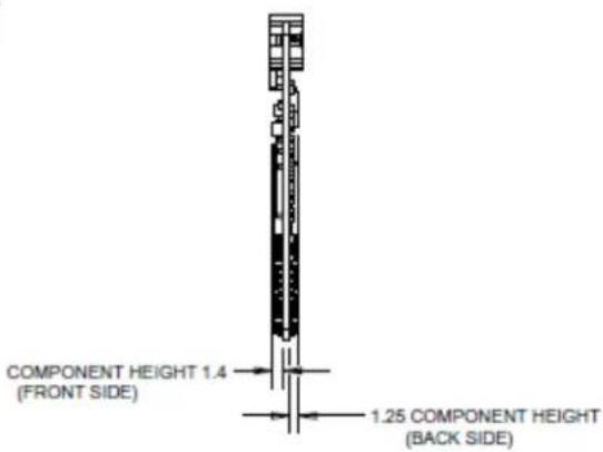
Figure 4-2 : Half-Slim SATA 8-64GB Side View
4.1.2 Half-Slim SATA 128GB-256GB capacity
4.2 mSATA Form Factor
Complies with MO-300A Standard
| Parameter | Specifications |
| Width | 30mm |
| Length | 50.95mm |
| Thickness (max) | 3.4mm (8-64GB), 3.2mm (128-256GB) |
| Typical Weight | 5.2g (8GB), 5.7g (16GB), 6.7g (32-64GB), 6.8g (128-256GB) |
Table 4-2: Mechanical Informaon - mSATA form factor
4.2.1 mSATA 8GB-64GB capacity

Figure 4-3 : mSATA 8-64GB Top View

Figure 4-4 : mSATA 8-64GB Side View
4.2.2 mSATA 128GB-256GB capacity

Figure 4-5 : mSATA 128-256GB Top View

Figure 4-6 : mSATA 128-256GB Side View
4.3 mSATA Mini Form Factor
Complies with MO-300B Standard
| Parameter | Specifications |
| Width | 30mm |
| Length | 26.80mm |
| Thickness (max) | 2.2mm (8GB), 3.2mm (16-128GB) |
| Typical Weight | 3.0g (8GB), 3.3g (16GB), 3.4g (32GB), 3.5g (64-128GB) |
Table 4-3: Mechanical Informaon - mSATA Mini form factor
4.3.1 mSATA Mini 8GB capacity
4.3.2 mSATA Mini 16GB-128GB capacity
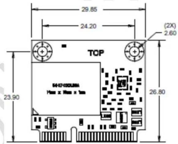
Figure 4-7 : mSATA Mini 16-128GB Top View

Figure 4-8 : mSATA Mini 16-128GB Side View
5. Environmental Specifications
5.1 Temperature
| Parameter | Specicaons |
| Operational | 0°C to 70°C |
| Storage | -55°C to 85°C |
| Maximum temperature gradient | 1°C per minute |
Table 5-1: SanDisk SSD U100 Temperature Specicaon
5.2 Humidity
| Parameter | Specicaons |
| Operational | |
| Humidity (Non condensation) | 5% to 95% |
| Maximum wet bulb | 35°C |
| Non-operational | |
| Humidity (Non condensation) | 5% to 95% |
| Maximum wet bulb | 40°C |
| Maximum relative humidity gradient | 20% per hour |
Table 5-2: SanDisk SSD U100 Humidity Specification
5.3 Vibration
| Parameter | Specicaons |
| Operational / Non-operational | 5gRMS, 10-2000 Hz, 3 axes |
Table 5-3: SanDisk SSD U100 Vibraon Specicaon
5.4 Shock
| Parameter | Acceleron Force | Half Sine pulse duraon |
| Operational / Non operational | 1000G | 1ms |
| 1500G | 0.5ms |
Table 5-4: SanDisk SSD U100 Shock Specicaon
5.5 Altitude
| Parameter | Specicaons |
| Non-Operational | -1500ft (-457m) to 40,000ft (12,192m) |
| Operational | -1500ft (-457m) to 10,000ft (3048m) |
Table 5-5: SanDisk SSD U100 Altude Specicaon
5.6 Electrostatic Discharge (ESD)
The SanDisk SSD U100's are ESD tested per IEC 61000-4-2 Standard.
| Parameter | Test Voltage |
| Contact | 2kV, 4kV |
| Air | 4kV, 8kV |
Table 5-6: SanDisk SSD U100 ESD Specicaon
5.7 Acoustics
The SSD U100 does not generate any acouscs noise (0dB).
5.8 EMI/RFI Compliance
The SanDisk SSD U100 is cered to comply with the following standards.
| Standard |
| FCC Part 15 Class B |
| IECS-003 Class B |
| EN 55022 Class B |
| EN 55024 |
| KCC No. 2008-39 |
| KCC No. 2008-38 |
| CNS 13438 |
| VCCI: 2006 |
| AS/NZS CISPR 22: 2006 |
Table 5-7: SanDisk SSD U100 EMI/RFI Compliance
5.9 RoHS
European union's restricon on use of hazardous substances in electrical and electronic equipment (EU RoHS) Direcve 2002/95/EC. China's management methods for controlling polluon by electronic informaon products (China RoHS).
5.10 Regulations
The SanDisk SSD U100 is cered with the following cercaons:
| Standard |
| CE |
| UL (with file number) |
| CSA (or ULc) |
| CE |
| WEEE |
| TUV/SEMKO/UL/etc. |
| MIC (Korea) (with certification number) |
| BSMI (Taiwan) (with applicant code number) |
| VCCI (Japan) |
| C-Tick (Australia) |
| FCC |
| China RoHS |
| HF (Halogen Free) |
| EuP |
Table 5-8: SanDisk SSD U100 Regulaon Standards
6. Reliability Characteristics
6.1 Error Rate
Non-recoverable error rate is 1 error per 1016 bits read.
6.2 MTTF (Mean-Time-To-Failure)
The reliability gure of merit most oen used for electronic equipment is Mean-Time-To-Failure (MTTF). SanDisk esmates MTTF using a predicon methodology based in accordance with the Telcordia Special Report SR-332. The predicon is based on a Parts Stress Analysis.
Quality levels were dened as industrial grade (I) for all of the components. The detailed predicon for the system was performed at a temperature of 25° C in a GB environment.
The following table summarizes the esmated MTTF results for each capacity.
| Capacity | Condition | MTTF (Hours) | Estimated FITs |
| 8GB | Telcordia SR-332, GB, 25°C | TBD | TBD |
| 16GB | Telcordia SR-332, GB, 25°C | TBD | TBD |
| 32GB | Telcordia SR-332, GB, 25°C | TBD | TBD |
| 64GB | Telcordia SR-332, GB, 25°C | TBD | TBD |
| 128GB | Telcordia SR-332, GB, 25°C | TBD | TBD |
| 256GB | Telcordia SR-332, GB, 25°C | TBD | TBD |
Table 6-1: SanDisk SSD U100 MTTF
7. Interface
7.1 Supported Standards
The SSD U100 complies with the following standards:
• SATA 6Gb/s, Revision 3.0
• ATA Command Set ACS-2
7.2 Pin Assignments - Half-Slim SATA connector
SIGNAL Connector Pinout:
| Pin # | Signal Name | Descripon |
| S1 | GND | 2nd mate |
| S2 | A+ | RxP |
| S3 | A- | RxM |
| S4 | GND | 2nd mate |
| S5 | B- | TxM |
| S6 | B+ | TxP |
| S7 | GND | 2nd mate |
POWER Connector Pinout:
| Pin # | Signal Name | Descripon |
| P1 | V33 | Not connected |
| P2 | V33 | Not connected |
| P3 | V33 | Not connected |
| P4 | GND | 1st mate |
| P5 | GND | 2nd mate |
| P6 | GND | 2nd mate |
| P7 | V5 | 5V power input, pre-charge, 2nd mate |
| P8 | V5 | 5V power input |
| P9 | V5 | 5V power input |
| P10 | GND | 2nd mate |
| P11 | DAS/RSS | Device Activity Signal |
| P12 | GND | 1st mate |
| P13 | V12 | Not connected |
| P14 | V12 | Not connected |
| P15 | V12 | Not connected |
Table 7-1: Standard SATA Connector Pin Assignment
7.3 Pin Assignments - mSATA
| Pin # | Assignment | Descripon | Pin # | Assignment | Descripon |
| 1 | No Connect | 2 | +3.3V | 3.3V Source | |
| 3 | No Connect | 4 | GND | Return Current Path | |
| 5 | No Connect | 6 | No Connect | ||
| 7 | No Connect | 8 | No Connect | ||
| 9 | GND | Return Current Path | 10 | No Connect | |
| 11 | No Connect | 12 | No Connect | ||
| 13 | No Connect | 14 | No Connect | ||
| 15 | GND | Return Current Path | 16 | No Connect | |
| 17 | No Connect | 18 | GND | Return Current Path | |
| 19 | No Connect | 20 | No Connect | ||
| 21 | GND | Return Current Path | 22 | No Connect | |
| 23 | +B - TXP | Transmitter Differential Signal Pair | 24 | +3.3V | 3.3V Source |
| 25 | -B - TXN | Transmitter Differential Signal Pair | 26 | GND | Return Current Path |
| 27 | GND | Return Current Path | 28 | No Connect | |
| 29 | GND | Return Current Path | 30 | No Connect | |
| 31 | -A - RXN | Receiver Differential Signal Pair | 32 | No Connect | |
| 33 | +A - RXP | Receiver Differential Signal Pair | 34 | GND | Return Current Path |
| 35 | GND | Return Current Path | 36 | No Connect | |
| 37 | GND | Return Current Path | 38 | No Connect | |
| 39 | +3.3V | 3.3V Source | 40 | GND | Return Current Path |
| 41 | +3.3V | 3.3V Source | 42 | PWR_LOSS | Power Loss Indicator |
| 43 | No Connect | 44 | DEVSLP | SATA PHY Power Control | |
| 45 | No Connect | 46 | No Connect | ||
| 47 | No Connect | 48 | No Connect | ||
| 49 | DA/DSS | Device Activity | 50 | GND | Return Current Path |
| 51 | Presence Detection | Pulled low by the device | 52 | +3.3V | 3.3V Source |
Table 7-2: mSATA Connector Pin Assignment
8. Supported ATA Commands
The following table denotes some of the common ATA commands supported by the SSD U100. Specs of each ATA command's operaon can be found in the ATA/ATAPI Command Set ACS-2 document.
| Command Name | ATA8 | Code | ||
| Check Power Mode | M | E5h | ||
| Data Set Management | O | 06h | ||
| Trim | 01h | |||
| Device Configuration Overlay | O | B1h | ||
| DCO sub-commands: | Restore | C0h | ||
| Freeze Lock | C1h | |||
| Identify | C2h | |||
| Set | C3h | |||
| Identify DMA | C4h | |||
| Set DMA | C5h | |||
| Download Microcode | O | 92h | ||
| Download (with offsets) and save microcode. | 03h | |||
| Download (without offsets) and save microcode. | 07h | |||
| Execute Device Diagnostic | M | 90h | ||
| Flush Cache | M | E7h | ||
| Flush Cache Ext | O | EAh | ||
| Identify Device | M | Ech | ||
| Idle | M | E3h | ||
| Idle Immediate | M | E1h | ||
| Initialize Drive Parameters | Obs | 91h | ||
| NOP | O | 00h | ||
| Read Buffer | O | E4h | ||
| Read DMA | M | C8h | ||
| Read DMA Ext | O | 25h | ||
| Read DMA w/o Retry | Obs | C9h | ||
| Read FPDMA Queued | O | 60h | ||
| Read Log Ext | O | 2Fh | ||
| Read Multiple | M | C4h | ||
| Read Multiple Ext | O | 29h | ||
| Read Native Max Address | O | F8h | ||
| Read Native Max Addr Ext | O | 27h | ||
| Read Sectors | M | 20h | ||
| Read Sectors Ext | O | 24h | ||
| Read Sectors w/o Retry | Obs | 21h | ||
| Read Verify Sectors | M | 40h | ||
| Read Verify Sectors Ext | O | 42h | ||
| Read Verify Sectors w/o Retry | Obs | 41h | ||
| Recalibrate | Obs | 1Xh | ||
| Sanitize | O | B4h | ||
| Sanitize sub-commands: | Sanitize Status Ext | 00h | ||
| Block Erase Ext | 12h | |||
| Sanitize Freeze Lock Ext | 20h | |||
| Security Disable Password | O | F6h | ||
| Security Erase Prepare | O | F3h | ||
| Security Erase Unit | O | F4h | ||
| Security Freeze Lock | O | F5h | ||
| Security Set Password | O | F1h | ||
| Security Unlock | O | F2h | ||
| Seek | Obs | 7Xh | ||
| Set Features | M | EFh | ||
| Set Features sub-commands: | Enable write cache | 02h | ||
| Set transfer mode | 03h | |||
| Enable Advanced Power Management (APM) | 05h | |||
| Enable SATA features | 10h | |||
| DMA Setup FIS Auto-Activate Optimization | 02h | |||
| Device-Initiated Interface Power Management | 03h | |||
| Software Setting Preservation | 06h | |||
| Disable read look-ahead | 55h | |||
| Disable reverting to power-on defaults | 66h | |||
| Disable write cache | 82h | |||
| Disable Advanced Power Management (APM) | 85h | |||
| Disable SATA features | 90h | |||
| DMA Setup FIS Auto-Activate Optimization | 02h | |||
| Device-Initiated Interface Power Management | 03h | |||
| Software Setting Preservation | 06h | |||
| Enable read look-ahead | AAh | |||
| Enable reverting to power-on defaults | CCh | |||
| Set Max Address | O | F9h | ||
| Security Extension sub-commands: | Set Max Set Password | 01h | ||
| Set Max Lock | 02h | |||
| Set Max Unlock | 03h | |||
| Set Max Freeze Lock | 04h | |||
| Set Max Set Password DMA | 05h | |||
| Set Max Unlock DMA | 06h | |||
| Set Max Address Ext | O | 37h | ||
| Set Multiple Mode | M | C6h | ||
| Sleep | M | E6h | ||
| Smart | O | B0h | ||
| Smart sub-commands: | Read Attribute Values (Read Data) | D0h | ||
| Read Attribute Thresholds | Obs | D1h | ||
| Enable/Disable Attribute Autosave | O | D2h | ||
| Save Attribute Values | D3h | |||
| Execute Offline Immediate: | LBA Low | D4h | ||
| Execute off-line immediate routine | 00h | |||
| Execute Short Self-test routine (Offline) | 01h | |||
| Execute Extended Self-test routine (Offline) | 02h | |||
| Abort off-line immediate routine | 7Fh | |||
| Execute Short Self-test routine (Captive) | 81h | |||
| Execute Extended Self-test routine (Captive) | 82h | |||
| Read Log | D5h | |||
| Write Log | D6h | |||
| Enable Operations | D8h | |||
| Disable Operations | D9h | |||
| Read Status | DAh | |||
| Disable Auto Offline | Obs | DBh | ||
| Standby | M | E2h | ||
| Standby Immediate | M | E0h | ||
| Write Buffer | O | E8h | ||
| Write DMA | M | CAh | ||
| Write DMA Ext | O | 35h | ||
| Write DMA w/o Retry | Obs | CBh | ||
| Write FPDMA Queued | O | 61h | ||
| Write Log Ext | O | 3Fh | ||
| Write Multiple | M | C5h | ||
| Write Multiple Ext | O | 39h | ||
| Write Sectors | M | 30h | ||
| Write Sectors Ext | O | 34h | ||
| Write Sectors w/o Retry | Obs | 31h | ||
| Write Uncorrectable Ext | O | 45h | ||
| Pseudo-UECC with Logging | 55h | |||
M = Mandatory. O = Oponal. Obs = Obsolete, But Supported
Table 8-1: Supported ATA Commands
8.1 Identify Data
The following table denotes the species of the Idenfy Data returned by the SSD U100.
| Word Address | Default Value | Total Bytes | Data Field Type Informaon |
| 0 | 0040h | 2 | ATA General configuration: bit-significant information |
| 1 | 3FFFh | 2 | ATA Default number of cylinders (depends on capacity) |
| 2 | C837h | 2 | Reserved |
| 3 | 0010h | 2 | Default number of heads |
| 4-5 | 0000h | 4 | Obsolete |
| 6 | 003Fh | 2 | Default number of sectors per track |
| 7-9 | 0000h | 6 | Obsolete |
| 10-19 | ASCII | 20 | Serial number in ASCII (left-justified) |
| 20-22 | 0000h | 6 | Obsolete |
| 23-26 | MJ.MN.XX | 8 | Firmware revision in ASCII |
| 27-46 | SanDisk SSD U100 XXXGB | 40 | Model number in ASCII (left-justified) for SSD U100 MLC |
| 47 | 8001h | 2 | Maximum No. of sectors in Read/Write Multiple command |
| 48 | 0000h | 2 | Reserved |
| 49 | 2F00h | 2 | LBA and MWDMA modes supported |
| 50 | 4000h | 2 | Capabilities |
| 51 | 0200h | 2 | PIO data transfer cycle timing mode |
| 52 | 0000h | 2 | Obsolete |
| 53 | 0007h | 2 | Field validity |
| 54 | XXXXh | 2 | Current number of cylinders (depends on capacity) |
| 55 | 0010h | 2 | Current number of heads |
| 56 | 003Fh | 2 | Current sectors per track |
| 57-58 | XXXXh | 4 | Current capacity in sectors (LBAs) |
| 59 | 9101h | 2 | Sanitize options and Multiple sector setting (Multiple = 1) |
| 60-61 | XXXXh | 4 | Total number of sectors addressable in LBA Mode |
| 62 | 0000h | 2 | Obsolete |
| 63 | 0007h | 2 | Bits:15-8: Multiword DMA mode activeBits: 0-7: Multiword DMA modes supported |
| 64 | 0003h | 2 | Advanced PIO modes supported |
| 65 | 0078h | 2 | Minimum multiword DMA transfer cycle time per word (ns) |
| 66 | 0078h | 2 | Recommended multiword DMA transfer cycle time per word in ns |
| 67 | 0078h | 2 | Minimum PIO transfer without flow control |
| 68 | 0078h | 2 | Minimum PIO transfer with IORDY flow control |
| 69 | 5200h | 2 | ACS2 Additional Supported - Deterministic Trim |
| 70-74 | 0000h | 10 | Reserved |
| 75 | 001Fh | 2 | Queue Depth |
| 76 | 050Eh | 2 | SATA capabilities |
| 77 | 000Xh | 2 | SATA Additional capabilities (0002=1.5Gb/s, 0004=3Gb/s, 0006=6Gb/s) |
| 78 | 004Ch | 2 | SATA Features Supported |
| 79 | 0040h | 2 | SATA Features Enabled |
| 80 | 03F0h | 2 | Major Version number |
| 81 | 0110h | 2 | Minor Version number |
| 82 | 746Bh | 2 | Command set supported |
| 83 | 7D01h | 2 | Command sets supported |
| 84 | 4123h | 2 | Command set/feature supported extension |
| 85 | 7469h | 2 | Command set/feature enabled |
| 86 | BD01h | 2 | Command set/feature enabled |
| 87 | 4123h | 2 | Command set/feature default |
| 88 | 007Fh | 2 | Ultra DMA Mode supported and selected |
| 89 | 0001h | 2 | Time required for security erase-unit completion (all capacities complete < 2 minutes) |
| 90 | 0001h | 2 | Time required for Enhanced security erase completion (all capacities complete < 2 minutes) |
| 91 | 0000h | 2 | Current advanced power management value |
| 92 | FFFEh | 2 | Master Password Identifier |
| 93 | 0000h | 2 | Hardware Reset Result |
| 94 | 0000h | 2 | Current AAM Value |
| 95 | 0000h | 2 | Stream Min Request Size |
| 96 | 0000h | 2 | Streaming Transfer Time-DMA |
| 97 | 0000h | 2 | Streaming Access Latency |
| 98-99 | 0000h | 4 | Streaming Performance Granularity |
| 100-103 | XXXXh | 8 | 48-bit # of LBA's |
| 104 | 0000h | 2 | Streaming Transfer Time-PIO |
| 105 | 0008h | 2 | Max # 512-byte Blocks in LBA Range Entries |
| 106 | 4000h | 2 | Physical Sector Size/Logical |
| 107 | 0000h | 2 | Inter-Seek Delay for ISO7779 |
| 108-111 | 5001B440XXXXXXXXXh | 8 | WWN |
| 112-115 | 0000h | 8 | Reserved |
| 116 | 0000h | 2 | Reserved for TLC |
| 117-118 | 0000h | 4 | Logical Sector Size |
| 119 | 4014h | 2 | Command/Feature Sets Supported #4 |
| 120 | 4014h | 2 | Command/Feature Sets Enabled |
| 121-126 | 0000h | 12 | Reserved |
| 127 | 0000h | 2 | Obsolete |
| 128 | 0021h | 2 | Security Status |
| 129-159 | 0000h | 62 | Reserved vendor-unique bytes |
| 160-167 | 0000h | 16 | Reserved |
| 168 | 0004h | 2 | Device Nominal Form Factor |
| 169 | 0001h | 2 | ATA8-ACS2 Data Set Management Support |
| 170-175 | 0000h | 12 | Reserved |
| 176-205 | 0000h | 60 | Current Media Serial Number (not supported) |
| 206 | 0000h | 2 | SCT Command Transport |
| 207-208 | 0000h | 4 | Reserved for CE-ATA |
| 209 | 4000h | 2 | Alignment-Logical within Physical Block |
| 210-211 | 0000h | 4 | Wr/Rd/Vfy Sector Count Mode 3 |
| 212-213 | 0000h | 4 | Wr/Rd/Vfy Sector Count Mode 2 |
| 214 | 0000h | 2 | NV Cache Capabilities |
| 215-216 | 0000h | 4 | NV Cache Size in Logical Blocks |
| 217 | 0001h | 2 | Nominal Media Rotation Rate |
| 218 | 0000h | 2 | Reserved |
| 219 | 0000h | 2 | NV Cache Options |
| 220 | 0000h | 2 | Wr/Rd/Vfy Feature Set-Current Mode |
| 221 | 0000h | 2 | Reserved |
| 222 | 1031h | 2 | Transport Major Version Number |
| 223 | 0000h | 2 | Transport Minor Version Number |
| 224-233 | 0000h | 20 | Reserved for CE-ATA |
| 234 | 0008h | 2 | Min Sector Count for Download Microcode Mode 3 |
| 235 | 0010h | 2 | Max Sector Count for Download Microcode Mode 3 |
| 236-254 | 0000h | 38 | Reserved for CE-ATA |
| 255 | XXXXh | 2 | Integrity Word-Checksum |
Table 8-2: Identify Data Values
8.2 Log Pages
The following table denotes the list of supported Log Pages accessible through SMART Write Log, SMART Read Log, Read Log Ext and Write Log Ext commands.
| Log Address | Total Pages | Log Address Descripon |
| 0x00 | 1 | General Purpose Log Directory |
| 0x01 | 1 | Summary SMART Error Log |
| 0x03 | ‘n’ | Ext Comprehensive SMART Error Log |
| 0x04 | ‘n’ | Device Statistics Log - SSD Statistics |
| 0x06 | 1 | SMART Self-Test Log |
| 0x10 | 1 | NCQ Error Log |
| 0x11 | 1 | SATA PHY Event Counters Log |
| 80h-9Fh | 16 | Host Vendor-specific Logs |
Table 8-3: Supported SMART Log Pages
9. Ordering information
9.1 SanDisk SSD U100 MLC Products Ordering Information
| SDSA5XK-CCCG-YYYY | |
| SD | SanDisk |
| SA | SATA |
| 5 | Generation: 4 |
| X | Form factor:A - Half 1.8" form factor, Standard SATA connectorD - mSATA form factorF - mSATA Mini form factorG - 2.5" 7mm cased form factor |
| K | Flash Memory used: 24nm 64Gb MLC ABL |
| CCC | Capacity:008016032064128256 |
| G | Units: GB |
| YYYY | Customer code reference |
Table 9-1: SSD U100 MLC Ordering Informaon
Refer to the examples below as reference for ordering SKUs.
| SKU # | Details |
| SDSA5AK-032G-YYYY | 32GB SSD U100 MLC in Half 1.8" form factor, Standard SATA connector |
| SDSA5DK-064G-YYYY | 64GB SSD U100 MLC in mSATA form factor |
| SDSA5FK-128G-YYYY | 128 GB SSD U100 MLC in mSATA Mini form factor |
Table 9-2: Examples of decoded SKU for SSD U100 MLC Products
10. Contact information
USA
Tel: +1-408-470-4440
Fax: +1-408-470-4470
OEMinfo@sandisk.com
China
Tel: +86-755-8348-5218
Fax: +86-755-8348-5418
OEMChina@sandisk.com
Taiwan
Tel: +886-2-2515-2522
Fax: +886-2-2515-2295
OEMAsia@sandisk.com
Korea
Tel: +82-2-3452-9079
Fax: +82-2-3452-9145
Japan
Tel: +81-3-5423-8101
Fax: +81-3-5423-8102
OEMJapan@sandisk.com
Europe
Tel: +33-(1)-43-37-2131
Fax: +33-(1)-43-37-2111
OEMEurope@sandisk.com
Rest of the World & Israel
Tel: +972-9-764-5000
Fax: +972-3-548-8666
For more informaon, please visit www.sandisk.com/SSD


- TABLE OF CONTENTS
- INTRODUCTION 8
- GENERAL PRODUCT SPECIFICATIONS .... 17
- POWER CHARACTERISTICS....20
- PHYSICAL SPECIFICATION 24
- ENVIRONMENTAL SPECIFICATIONS....29
- RELIABILITY CHARACTERISTICS.... 32
- INTERFACE 33
- SUPPORTED ATA COMMANDS 35
- ORDERING INFORMATION 44
- CONTACT INFORMATION 45
- TABLE OF FIGURES
- TABLE OF TABLES
- INTRODUCTION
- 1.1 GENERAL DESCRIPTION
- 1.2 KEY FEATURES
- 1.3 FUNCTIONAL DESCRIPTION
- 1.4 ADVANCED FLASH MANAGEMENT
- 1.4.1 NON-VOLATILE WRITE CACHE
- 1.4.2 DEFECT AND ERROR MANAGEMENT
- 1.4.3 WEAR LEVELING
- 1.4.4 BAD BLOCK MANAGEMENT
- 1.5 ADVANCED LOW POWER MANAGEMENT
- 1.5.1 SLUMBER SATA LOW POWER MODE
- 1.5.2 DEVLSP SATA LOW POWER MODE
- 1.6 BACKGROUND GARBAGE COLLECTION
- 1.7 POWER CLASSES
- 1.8 PERFORMANCE THROTTLING
- GENERAL PRODUCT SPECIFICATIONS
- 2.1 INTERFACE
- 2.2 CAPACITY
- 2.3 PERFORMANCE 11
- 2.3.1 MULTI-LEVEL CELL (MLC) PERFORMANCE
- 2.4 ENDURANCE
- 2.4.1 MULTI-LEVEL CELL (MLC) ENDURANCE
- POWER CHARACTERISTICS
- 3.1 SUPPLY VOLTAGE
- 3.2 GRACEFUL POWER-OFF REQUIREMENTS
- 3.3 AVERAGE POWER CONSUMPTION
- 3.3.1 MULTI-LEVEL CELL (MLC) AVERAGE POWER CONSUMPTION
- 3.4 ACTIVE POWER CONSUMPTION
- 3.4.1 MULTI-LEVEL CELL (MLC) ACTIVE POWER CONSUMPTION
- 3.5 LOW POWER MODE CONSUMPTION
- PHYSICAL SPECIFICATION
- 4.1 HALF-SLIM SATA FORM FACTOR
- 4.1.1 STANDARD SATA 8GB-64GB CAPACITY
- 4.1.2 HALF-SLIM SATA 128GB-256GB CAPACITY
- 4.2 MSATA FORM FACTOR
- 4.2.1 MSATA 8GB-64GB CAPACITY
- 4.2.2 MSATA 128GB-256GB CAPACITY
- 4.3 MSATA MINI FORM FACTOR
- 4.3.1 MSATA MINI 8GB CAPACITY
- 4.3.2 MSATA MINI 16GB-128GB CAPACITY
- ENVIRONMENTAL SPECIFICATIONS
- 5.1 TEMPERATURE
- 5.2 HUMIDITY
- 5.3 VIBRATION
- 5.4 SHOCK
- 5.5 ALTITUDE
- 5.6 ELECTROSTATIC DISCHARGE (ESD)
- 5.7 ACOUSTICS
- 5.8 EMI/RFI COMPLIANCE
- 5.9 ROHS
- 5.10 REGULATIONS
- RELIABILITY CHARACTERISTICS
- 6.1 ERROR RATE
- 6.2 MTTF (MEAN-TIME-TO-FAILURE)
- INTERFACE
- 7.1 SUPPORTED STANDARDS
- 7.2 PIN ASSIGNMENTS - HALF-SLIM SATA CONNECTOR
- SUPPORTED ATA COMMANDS
- 8.1 IDENTIFY DATA
- 8.2 LOG PAGES
- ORDERING INFORMATION
- 9.1 SANDISK SSD U100 MLC PRODUCTS ORDERING INFORMATION
- CONTACT INFORMATION
Brand : SANDISK
Model : SSD 64 GB
Category : SSD