
DR24V1WGLP - Gas stove DANBY - Free user manual and instructions
Find the device manual for free DR24V1WGLP DANBY in PDF.


| Product Type | Gas Stove |
| Brand | Danby |
| Model | DR24V1WGLP |
| Width | 24 inches (61 cm) |
| Depth | 25.6 inches (65 cm) |
| Height | 36.2 inches (92 cm) |
| Weight | 132 lbs (60 kg) |
| Fuel Type | Natural Gas or LP (convertible) |
| Number of Burners | 4 |
| Burner Power (Maximum) | 12,000 BTU (front left) |
| Oven Capacity | 3.5 cubic feet (99 liters) |
| Oven Type | Gas oven with bake and broil |
| Ignition Type | Electronic (spark) ignition |
| Safety Features | Flame failure device on all burners and oven |
| Door Type | Standard oven door with window |
| Color | White (W in model) |
| Warranty | 1 year parts and labor |
| Certifications | CSA, UL |
| Cleaning | Manual clean; removable burner grates and caps |
| Replacable Parts | Burner heads, igniters, knobs, oven door gasket available |
Frequently Asked Questions - DR24V1WGLP DANBY
User questions about DR24V1WGLP DANBY
0 question about this device. Answer the ones you know or ask your own.
Ask a new question about this device
Download the instructions for your Gas stove in PDF format for free! Find your manual DR24V1WGLP - DANBY and take your electronic device back in hand. On this page are published all the documents necessary for the use of your device. DR24V1WGLP by DANBY.
USER MANUAL DR24V1WGLP DANBY
OWNER'S MANUAL MANUAL DEL PROPIETARIO
COMPACT GAS RANGE
Owner's Manual....1 - 26
Danby Products Limited, Guelph, Ontario, Canada N1H 6Z9
Danby Products Inc. Findlay, Ohio, U.S.A. 45840
www.danby.com
f in x p
Welcome to the Danby family.
We are proud of our quality products and we believe in dependable service. We suggest that you read this owner's manual before plugging in your new appliance as it contains important operation information, safety information, troubleshooting, and maintenance tips to ensure the reliability and longevity of your appliance.
You are entitled to the warranty coverage as described in the owner's manual provided with your new appliance.
- Please write down your appliance information below. You must keep the original proof of purchase receipt to validate and receive warranty services.
- Register your product online and receive a FREE 2 MONTH WARRANTY EXTENSION after filling out a product survey, at www.danby.com/support/product-registration/
Model Number: ____
Serial Number: ____
Date of Purchase: ____
Need Help?
- Read your Owner's Manual for installation help, troubleshooting, and maintenance assistance.
- Visit www.Danby.com to access self-service tools, FAQs and much more by searching your model number in the search bar.
- For the Quickest Customer Service, please fill out the web form at www.danby.com/support. Your submission will go directly to an expert on your particular appliance. Our average response times are between 20 minutes and 2 hours, during EST business hours.
- Call 1-800-263-2629 - please note that during peak hours, hold times can exceed one hour.

Important Safety Information READ AND FOLLOW ALL SAFETY INSTRUCTIONS
WARNING
If the information in these instructions is not followed exactly, a fire or explosion may result, causing property damage, personal injury, or death.
- Do not store or use gasoline or other flammable vapors and liquids in the vicinity of this or any other appliance.
WHAT TO DO IF YOU SMELL GAS
- Do not attempt to light any appliance.
- Do not touch any phone in your building.
- Immediately call your gas supplier from a neighbor's phone and follow their instructions.
- If you cannot reach your gas supplier, call the fire department.
Note: Installation and service must be performed by a qualified installer, service agency, or the gas supplier.
WARNING
Never Operate the Top Surface Cooking Section of This Appliance Unattended
Failure to follow this warning may result in fire, explosion, or burn hazards that could cause property damage, personal injury, or death. If a fire occurs, stay away from the appliance and immediately call your fire department.
DO NOT ATTEMPT TO EXTINGUISH AN OIL/GREASE FIRE WITH WATER.
IMPORTANT
- When installed in the United States, this range must be installed in accordance with local regulations or, in the absence of local codes, the most recent version of the National Fuel Gas Code (ANSI Z223.1).
- Underwriters Laboratories has approved the design of this series. There are several safety measures you should take, as with any gas-powered equipment that produces heat. Be sure to read the Use & Care Guide thoroughly for these instructions.
- This range must be electrically grounded in accordance with local codes or, in the absence of such codes, with the National Electrical Code ANSI/NFPA No. 70—latest edition when installed in the United States.

Important Safety Information READ AND FOLLOW ALL SAFETY INSTRUCTIONS
WARNING - TIP OVER HAZARD
- A child or adult can tip the appliance and be killed
- Verify the anti-tip bracket has been properly installed to the floor
- Ensure the anti-tip bracket is re-engaged when the range is moved
- Do not operate the range without the anti-tip bracket in place and engaged
- Failure to follow these instructions can result in death or serious burns to children or adults
ANTI-TIP DEVICES
To reduce the risk of the appliance tipping by abnormal usage or improper door loading, the appliance must be secured by installing anti-tip devices. There are two anti-tip devices that must be installed to ensure the appliance is safe.
Note: If the range is ever relocated both anti-tip devices must be removed and installed at the new location.
ANTI-TIP BRACKET
Installed on either the left or the right rear leg. To install the anti-tip bracket:
- Place the anti-tip bracket (1) on the floor where the range will be installed.
- Mark the location of the hole in the anti-tip bracket.
- Use a 5/16" (8 mm) drill bit to drill a hole in the floor and insert the provided screw (2) to secure the anti-tip brackets to the floor.
- Then install the anti-tip chain.
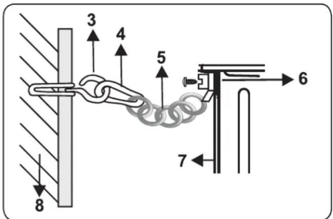
ANTI-TIP CHAIN
- Use a wall plug to fasten the hook (3) to the kitchen wall.
- With the help of the locking mechanism (4), connect the safety chain (5) to the hook.
INSTALL BOTH ANTI-TIP DEVICES
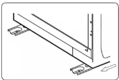
- Slide the range back and into position, ensuring that the anti-tip bracket is positioned over the rear foot of the appliance.
- Using the screw attachment (6), tightly fix the chain to the back of the range (7).
- Remember the safety chain should be as short as practically possible to avoid the appliance from tilting forward, so the range should be very close to the back wall (8).


natural_image
Technical line drawing of a mechanical assembly with mounting brackets and fasteners (no text or symbols)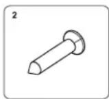

natural_image
Technical line drawing of a structural support frame with mounting brackets and a vertical load, showing no text or symbols.SAVE THESE INSTRUCTIONS!

Important Safety Information READ AND FOLLOW ALL SAFETY INSTRUCTIONS
WARNING
NEVER use this appliance as a space heater to heat or warm the room. Doing so may result in carbon monoxide poisoning and overheating of the oven.
GENERAL SAFETY REQUIREMENTS
Use this appliance for its intended purpose as described in this Owner's Manual.
Have your range installed and properly grounded by a qualified installer in accordance with the provided installation instructions. Any adjustment and service should be performed only by a qualified gas range installer or service technicians. Do not attempt to repair or replace any part of your range unless it is specifically recommended in this guide.
Your range is shipped from the factory set for use with natural gas. It can be converted for use with LP gas. If required, these adjustments must be made by a qualified technician in accordance with the installation instructions and local codes. The agency performing this work assumes responsibility for the conversion.
Have the installer show you the location of the range gas shut-off valve and how to turn it off if necessary.
Plug your range into a 120-volt grounded outlet only. Do not remove the round grounding prong from the plug. If in doubt about the grounding of the home electrical system, it is your responsibility and obligation to have an ungrounded outlet replaced with a properly grounded, three prong outlet in accordance with the National Electrical Code. Do not use an extension cord with this appliance.
Before performing any service, unplug the range or disconnect the power supply at the household distribution panel by removing the fuse or switching off the circuit breaker.
Be sure all packing materials are removed from the range before operating to prevent ignition of these materials.
Avoid scratching or impacting glass doors, the cooktop or control panel. Doing so may lead to glass breakage. Do not cook on a product with broken glass. Shock, fire or cuts may occur.
Do not leave children alone or unattended in an area where an appliance is in use. They should never be allowed to climb, sit or stand on any part of the appliance.
Do not store items of interest to children above a range or on the backguard of a range - children climbing on the range to reach items could be seriously injured.
Do not allow anyone to climb, stand or hang on the oven door, drawer or cooktop. They could damage the range or tip it over causing severe injury or death.
Never block the vents (air openings) of the range. They provide the air inlets and outlets that are necessary for the range to operate properly with correct combustion. Air openings are located at the rear of the cooktop, at the top and bottom of the oven door, and at the bottom of the range under the warming drawer, lower oven drawer or kick panel.
Use only dry pot holders—moist or damp pot holders on hot surfaces may result in burns from steam. Do not let pot holders touch surface burners, burner grates, or oven heating elements. Do not use a towel or other bulky cloth in place of pot holders.
Be careful not to touch hot surfaces of the range. Potentially hot surfaces include burners, grates, cooktop, backguard, oven and door interior and crevices around the oven door.
Do not heat unopened food containers. Pressure could build up and the container could burst, causing an injury.
SAVE THESE INSTRUCTIONS!

Important Safety Information READ AND FOLLOW ALL SAFETY INSTRUCTIONS
WARNING - FLAMMABLE MATERIALS
Do not store or use flammable materials in an oven or near the cooktop, including paper, plastic, pot holders, linens, wall coverings, curtains, drapes and gasoline or other flammable vapors and liquids.
Never wear loose-fitting or hanging garments while using the appliance. Avoid storing commonly used items in cabinets above the range and be careful when reaching over the range. Clothing in close proximity to burners or hot surfaces may ignite causing severe burns.
Do not let cooking grease or other flammable materials accumulate in or near the range. Grease in the oven or on the cooktop may ignite.
Clean ventilating hoods frequently. Grease should not be allowed to accumulate on the hood or filter.
WARNING - IN CASE OF FIRE
In the event of a fire, never pick up a flaming pot or pan. Turn the burner off if it is safe to do so. Extinguish the fire with a dry chemical or foam-type extinguisher.
Do not use water on grease fires. Water will spread the grease and will not extinguish the fire. Smother the fire with a tight fitting pot lid, cookie sheet or flat tray or use dry chemical or foam-type extinguisher.
If there is a fire in the oven during baking, smother the fire by closing the oven door and turning the oven off or use dry chemical or foam-type extinguisher.
COOKTOP SAFETY INSTRUCTIONS
Never leave the range unattended while a surface burner is ON. Foods, especially oily foods, may ignite resulting in fire that could spread to surrounding cabinets.
Never leave oil unattended while frying. If allowed to heat beyond its smoking point, oil may ignite resulting in fire that may spread to surrounding cabinets. Use a deep fat thermometer whenever possible to monitor oil temperature.
To avoid oil spillover and fire, use a minimum amount of oil when shallow pan-frying and avoid cooking frozen foods with excessive amounts of ice.
Use proper pan size and avoid pans that are unstable or easily tipped. Select cookware that is matched to the size of the burner. Burner flames should be adjusted so that they do not extend beyond the bottom of the pan. Excessive flames may be hazardous.
Always use the LITE position when igniting the top burners and make sure the burners have ignited.
When using glass or ceramic cookware, make sure it is suitable for cooktop service; others may break because of sudden changes in temperature.
To minimize the possibility of burns, ignition of flammable materials and spillage, the handle of a container should be turned toward the center of the range without extending over nearby burners.
When preparing flaming foods under a hood, turn the fan on.
Do not use a wok with a round metal support ring. The ring may trap heat and block air to the burner resulting in a carbon monoxide hazard.
Do not attempt to lift the cooktop if your range has sealed surface burners. Doing so may damage the gas tubing to the surface burners resulting in a gas leak and risk of fire.
Do not use aluminum foil to cover the grates or line any part of the cooktop. Doing so may result in carbon monoxide poisoning, overheating of the cooktop surfaces, or a potential fire hazard.
SAVE THESE INSTRUCTIONS!

Important Safety Information READ AND FOLLOW ALL SAFETY INSTRUCTIONS
WARNING
NEVER cover any slots, holes or passages in the oven bottom or cover and entire rack with materials such as aluminum foil. Doing so blocks air flow through the oven and may cause carbon monoxide poisoning. Aluminum foil linings may also trap heat, causing a fire hazard.
OVEN SAFETY INSTRUCTIONS
Stand away from the range when opening the oven door. Hot air or steam which escapes can cause burns to hands, face and/or eyes.
Keep the oven free from grease build-up. Grease in the oven may ignite.
Place oven racks in desired location while oven is cool. If rack must be moved while oven is hot, do not let potholder contact the hot heating element in the oven.
Place oven racks in desired location while oven is cool. If rack must be moved while oven is hot, be careful to avoid touching hot surfaces.
Pull the oven rack to the stop-lock position when loading and unloading food from the oven. This helps prevent burns from touching hot surfaces of the door and oven walls.
Do not leave items such as paper, cooking utensils or food in the oven when not in use. Items stored in an oven can ignite.
Do not leave items on the cooktop near the oven vent which is in the center of the backguard. Items may overheat resulting in a risk of fire or burns.
When using cooking or roasting bags in the oven, follow the manufacturer's directions.
Never broil with door open. Open-door broiling is not permitted due to overheating of control knobs.
WARNING
Read all safety instructions before using the product. Failure to follow these instructions may result in fire, electric shock, serious injury or death.
SAVE THESE INSTRUCTIONS!
INSTALLATION INSTRUCTIONS
BEFORE INSTALLATION
- Make sure there are no flammable or combustible materials in the vicinity (curtains, oil, cloth, etc) which may catch fire.
- The worktop and furniture surrounding the appliance must be made of materials resistant to temperatures above 212°F (100 °C).
- The appliance should not be installed directly above a dishwasher, fridge, freezer, washing machine or clothes dryer.
- The appliance can be placed close to other furniture on the condition that, in the area where the appliance is set up, the furniture's height does not exceed the height of the cooktop.
- To eliminate the risk of burns or fire when reaching over a hot surface element, cabinet storage space above the cooktop should be avoided. If cabinet storage space is to be provided above the cooktop, the risk can be reduced by installing a range hood that protrudes at least 5" (127 mm) beyond the front of the cabinets. Cabinets installed above a cooktop may be no deeper than 13" (330 mm).
WARNING FOR INSTALLATION AND PREPARATION FOR USE
The appliance must be installed by an authorized service person or qualified technician
- Incorrect installation may cause harm and damage for which the manufacturer accepts no responsibility and the warranty will not be valid
- Prior to installation, ensure that the local distribution conditions (electricity voltage and frequency and/or nature of the gas and gas pressure) and the adjustments of the appliance are compatible. The adjustment conditions for this appliance are stated on the label
- Ensure the laws, ordinances, directives and standards in force in the country of use are to be followed (safety regulations, proper recycling in accordance with the regulations, etc.).
INSTALLATION INSTRUCTIONS
INSTALLATION AND PREPARATION FOR USE
- Incorrect installation may cause harm and damage, for which the manufacturer accepts no responsibility and the warranty will not be valid.
- Prior to installation, ensure that the local distribution conditions (electricity voltage and frequency and/or nature of the gas and gas pressure) and the adjustments of the appliance are compatible. The adjustment conditions for this appliance are stated on the label.
- The laws, ordinances, directives and standards in force in the country of use are to be followed (safety regulations, proper recycling in accordance with the regulations, etc.).
- If the product contains removable shelf guides (wire racks) and the user manual includes recipes like yog urt, the wire racks shall be removed and the oven operated in the defined cooking mode. Removal of the Wire Shelf information is included in the CLEANING AND MAINTENANCE section.
INSTRUCTIONS FOR THE INSTALLER
Ventilation requirements
- For rooms with a volume of less than 175 ft ^3 (5m ^3 ), permanent ventilation of 15.5 inch ^2 (100 cm ^2 ) free area is required.
- For rooms with a volume of between 175 ft ^3 (5 m ^3 ) and 350 ft ^3 (10 m ^3 ), permanent ventilation of 7.75 inch ^2 (50 cm ^2 ) free area will be required, unless the room has a door which opens directly to outside air in which case no permanent ventilation is required.
- For rooms with a volume greater than 350 ft ^3 (10 m ^3 ), no permanent ventilation is required.



INSTALLATION INSTRUCTIONS
General instructions
- After removing the packaging material from the appliance and its accessories, ensure that the appliance is not damaged. If you suspect any damage, do not use it and contact an authorized service person or qualified technician immediately.
- Make sure that there are no flammable or combustible materials in the close vicinity, such as curtains, oil, cloth etc. which may catch fire.
- The worktop and furniture surrounding the appliance must be made of materials resistant to temperatures above 212 °F (100 °C).
- The appliance should not be installed next to a dishwasher, refrigerator, freezer, washing machine or clothes dryer.
- The appliance can be placed close to other furniture on condition that in the area where the appliance is set up, the furniture's height does not exceed the height of the cooktop.
Installation of the Cooker
- A qualified installer must perform installation and service.
- Important: Save for use by the neighborhood electrical inspector.
- Read and capture these guidelines for later reference
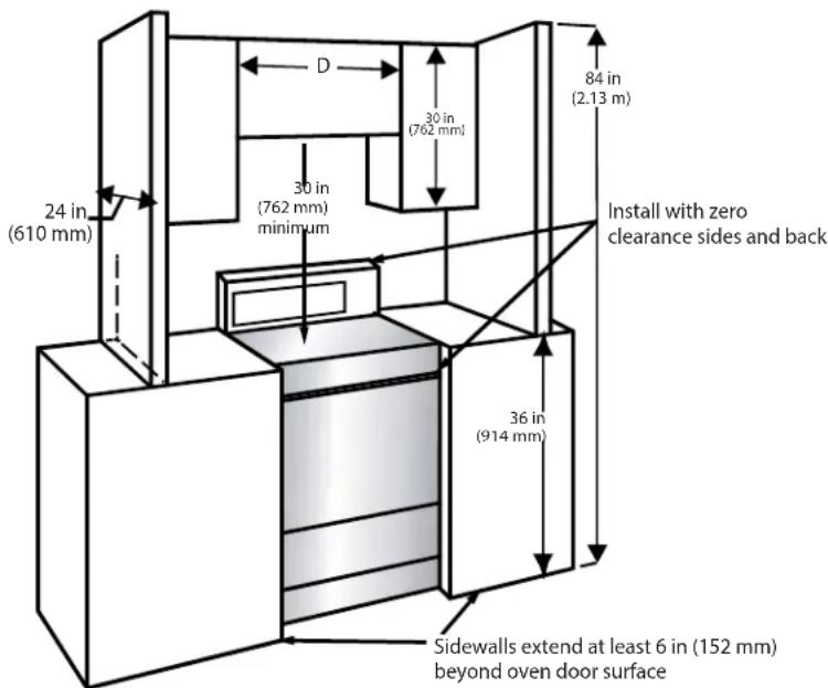
Dimensions and Clearances
- Make sure there are enough space between the range and any nearby flammable materials.
- Location-Confirm the installation site for the range
- Check the stability of the floor and the appropriateness of the electrical supply.
- The specified dimensions must be used.
- Minimum clearance is provided by the given dimensions. A stable and flat contact surface is required.
- Avoid cabinet storage space located above the surface units to eliminate the risk of burns or fire by reaching over heated surface units. The risk can be reduced by installing a range hood that projects horizontally a minimum of 5" (127 mm) beyond the bottom of the cabinets if cabinet storage is to be provided.
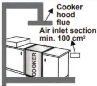
- If the kitchen furniture is higher than the cook-top, the kitchen furniture must be at least 4 inches (10 cm) away from the sides of appliance for air circulation.
- If a cooker hood or any cupboard is to be installed above the appliance, the safety distance between cooktop and any cupboard/cooker hood should be as shown below.

Proper positioning of the gas and electric outlet must be flush. Nothing located in shaded area can extend more than 2" (5.1 cm) from wall or the ange will not slide all the way back.
INSTALLATION INSTRUCTIONS
GAS CONNECTION
Assembly of gas supply and leakage check
Connect the appliance in accordance with applicable local and international standards and regulations. First, check what type of gas is installed on the cooker. This information is available on a sticker on the back of the cooker. You can find the information related to appropriate gas types and appropriate gas injectors in the technical data table. Check that the feeding gas pressure matches the values on the technical data table, to be able to get the most efficient use and to ensure the minimum gas consumption. If the pressure of used gas is different than the values stated or is not stable in your area, it may be necessary to assemble an available pressure regulator on the gas inlet. You should contact an authorized service center to make these adjustments.
Points that must be checked during flexible hose assembly
- If the gas connection is made by a flexible hose fixed onto the gas inlet of the hob, it must be fixed on by a pipe collar.
- Connect your appliance with a short and durable hose that is as close as possible to the gas source.
- The maximum permitted length of the hose is 36 inches (90 cm).
- The device should be connected in line with the relevant local gas standards.
- The hose must be kept clear of areas that may heat up to temperatures of more than 194 °F (90 °C).
- The hose must not be cracked, torn, bent or folded.
- Keep the hose clear of sharp corners and objects that could move.
- Before you assemble the connection, you must make sure the hose is not damaged. Use bubbly water or leakage fluids to perform the check. Do not use a naked flame to check for gas leakage.
- All metal items that are used during gas connection must be free from rust. Check the expiration date of any components used for connection.
Points that must be checked during fixed gas connection assembly
This appliance has been tested in accordance with the following standards:
• ANS Z21.1: Household Cooking Appliances
• CSA 1.1: Household Cooking Appliances
• CAN / CSA-C 22.2 No 61-M89 Household Cooking Ranges
- In Canada: Installation shall be in accordance with CAN 1-B149.1 and CAN 1-B149.2 Installation Codes for Gas Burning Appliances and or local codes.
- It is the responsibility of the owner and the installer to determine if additional requirements, such as local codes and/or standards, apply to specific installations. The installation shall conform with local codes or, in the absence of local codes, with the National Fuel Gas Code, ANSI Z223.1/NFPA 54 or, in Canada, the Natural Gas and Propane Installation Code, CSA B149.1.
The method used to assemble a fixed gas connection (gas connection made by threads, e.g. a nut) varies according to the country you are in. The most common parts for your country will be supplied with your appliance. Any other parts required can be supplied as spare parts.
During connection, always keep the nut on the gas manifold fixed while rotating the counter-part. Use appropriately-sized spanners for a secure connection. For surfaces between different components always use the seals provided in the gas conversion kit.
The seals used during connection should also be approved to be used in gas connections. Do not use plumbing seals for gas connections.
Remember that this appliance is ready to be connected to the gas supply in the country for which it has been produced. The main country of destination is marked on the rear cover of the appliance. If you need to use it in another country, any of the connections in the figure below may be required. In such a case, contact local authorities to learn the correct gas connection.
INSTALLATION INSTRUCTIONS
Note: Use pipe joint sealant on all male (outside) pipe threads to stop leaks. When tightening fittings, avoid allowing the gas pressure regulator to turn on the pipe.
- Construct an accessible place outside of the range and attach an external manual gas shut-off valve to the gas supply line.
Make sure you are aware of where and how to turn off the range's gas supply.
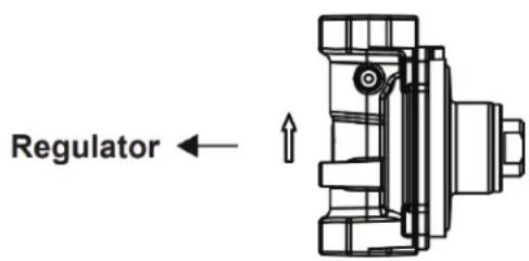
- Attach the 1/2" flare union adapter to the gas pressure regulator with a maximum torque of 15 ft-lbs


natural_image
Pure mechanical component diagram without any text, numbers, or symbolsWARNING
Please assemble the regulator to the appliance in the arrow direction shown on the regulator.
The Cooker must be installed and maintained by a suitably qualified gas registered technician in accordance with current safety legislation.
Do not use a naked flame to check for gas leaks.
Gas Pressure Regulator
The gas pressure regulator that is supplied with this appliance must be used. The inlet pressure to the regulator should be as follows for proper operations:
Natural Gas (NG - Methane):
Minimum pressure: 5" W.C.
Maximum pressure: 13" W.C.
Propane Gas (LP):
Minimum pressure: 12" W.C.
Maximum pressure: 13" W.C.
GAS CONVERSION (IF AVAILABLE)
Your appliance is designed to be operated with LP/NG gas. The gas burners can be adapted to different types of gas, by replacing the corresponding injectors and adjusting the minimum flame length suitable to the gas in use. For this purpose, the following steps should be performed.
Changing Pressure Setting of The Regulator
The regulator of the appliance is shipped to operate on NG. The inlet pressure of the gas supply shall be in accordance with the nominal inlet pressure of the regulator used on the range or 13" W.C. maximum.
-
WARNING: Before performing the conversion, be sure to shut off the gas and electrical power supply of the appliance.
-
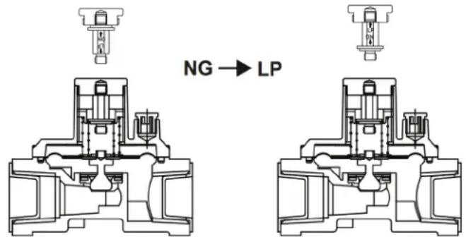
Twist the cap to get the adjustment rod. When the letter "NG" on the adjustment rod faces upward, the regulator outlet pressure is set to NG.

natural_image
Pure mechanical component diagram showing a shaft and nut assembly without any text or symbolsINSTALLATION INSTRUCTIONS
- To convert it from NG to LP, change direction of the adjustment rod. When the letter "LP" on the adjustment rod faces upward, the regulator outlet pressure is set to LP.

natural_image
Pure mechanical component diagram without any text, numbers, or symbols- Replace the cap back on the regulator.
Changing injectors Hob burners
- Cut off the main gas supply and unplug the appliance from the mains electrical supply.
- Remove the burner caps and the adapters.
- Use a 9/32 " (7 mm) spanner to unscrew the injectors.
- Replace the injector with the ones from the gas conversion kit, with the correct diameters for the type of gas that is going to be used, according to the gas injector table.
Electrical Connection and Safety
WARNING
The electrical connection of this appliance should be carried out by an authorised service person or qualified electrician, according to the instructions in this guide and in compliance with the current local regulations.
THE APPLIANCE MUST BE EARTHED.
- Before connecting the appliance to the power supply, the voltage rating of the appliance (stamped on the appliance identification plate) must be checked for correspondence to the available mains supply voltage, and the mains electric wiring should be capable of handling the appliance's power rating (also indicated on the identification plate).
- Proper Installation - Be sure your appliance is properly installed and grounded by a qualified technician. In the United States, install in accordance with the National Fuel Gas Code ANSI Z223.1/NPFA No.54, latest edition and National Electrical Code NFPA No.70 latest edition, and local electrical code requirements. In Canada, install in accordance with CAN/CGA B149.1 and CAN/CGA B149.2 and CSA Standard C22.1, Canadian Electrical code, Part 1 latest editions and local electrical code requirements.
- During installation, please ensure that isolated cables are used. An incorrect connection could damage your appliance. If the mains cable is damaged and needs to be replaced this should be done by a qualified person.
- Do not use adapters, multiple sockets and/or extension leads.
- The supply cord should be kept away from hot parts of the appliance and must not be bent or compressed. Otherwise the cord may be damaged, causing a short circuit.
INSTALLATION INSTRUCTIONS
- If the appliance is not connected to the mains with a plug, a all-pole disconnector (with at least 1/8" (3 mm) contact spacing) must be used in order to meet the safety regulations.
- The appliance is designed for a power supply of 110-120 V. If your supply is different, contact the authorized service personnel or qualified electrician.
- The power cable must be long enough to be connected to the appliance.
- The fused switch must be easily accessible once the appliance has been installed.
- Ensure all connections are adequately tightened.
- Fix the supply cable in the cable clamp and then close the cover.
CAUTION: Risk of Electric Shock. If the cord or plug becomes damaged, disconnect the appliance from the power supply and replace only with a cord or plug of the same type.
The power cord of this appliance is equipped with a three-prong (grounding) plug which mates with a standard three prong grounding wall receptacle to minimize the possibility of electric shock hazard from this appliance.
The customer should have the wall receptacle and circuit checked by a qualified electrician to make sure the receptacle is properly grounded.
Where a standard two-prong wall receptacle is encountered, it is the personal responsibility and obligation of the customer to have it replaced with a properly grounded three-prong wall receptacle.
Power supply cord with 3-prong grounding plug
Grauding type wall receptacle

natural_image
Simple line drawing of a mechanical component with no text or symbols
Ensure proper ground exists before use
WARNING
DO NOT, UNDER ANY CIRCUMSTANCES, CUT OR REMOVE THE THIRD (GROUND) PRONG FROM THE POWER CORD.
DO NOT USE AN ADAPTER. DO NOT USE AN EXTENSION CORD
OPERATING INSTRUCTIONS
PRODUCT FEATURES
- Cooktop
- Control panel
- Oven door handle
- Oven door
- Adjustable feet

CONTROL PANEL
- Oven Light Switch
- Oven Timer Control Knob
- Oven Indicator Light
- Oven Control Knob
- Hob Control Knob

OPERATING INSTRUCTIONS
USE OF PRODUCT
USE OF GAS BURNERS
Ignition of the burners
The position symbol above each control knob indicates the burner that the knob controls.
Manual ignition of the gas burners
If your appliance is not equipped with an ignition aid, or in case there is a failure in the electric network, follow the procedures listed below.
For hob burners: Push in the knob of the burner you wish to ignite and keep it pressed while turning it anti-clockwise until the knob is in the 'maximum' position. Continue pressing the knob and hold a lit match, taper or other manual aid to the upper circumference of the burner. Move the ignition source away from the burner as soon as you see a stable flame.
For oven burner: Push in and turn the oven control knob anti-clockwise until the knob is in the 'maximum' position. Hold a lit match, taper or other manual aid to to the ignition hole that is located on the front left corner of the burner. Move the ignition source away as soon as you see a stable flame.
Electrical ignition by control knob
Push in the knob of the burner you wish to ignite and keep it pressed while turning it anti-clockwise until the knob is in the 90 degrees position. The microswitch under the knob will create sparks through the spark plug for as long as the control knob is pressed. Press the knob until you see a stable flame on the burner.
Flame safety device
Hob burners
Hobs equipped with a flame failure device provide security in case of an accidentally extinguished flame. For this reason, during ignition, keep the knob pressed until you see stable flames.
Hold down the control for approximately 10 to
15 seconds after the burner has lit. Releasing the control too soon will extinguish the flame. If such a case occurs, the device will block the burners gas lines and will avoid any accumulation of unburned gas. Wait 90 seconds before re-igniting an extinguished gas burner.
Oven / Grill (If available) Burners
Regardless of the model of your appliance, all oven burners are equipped with a gas safety device. For this reason, during ignition, keep the oven knob pressed until you see stable flames.
Hold down the control for approximately 10 to 15 seconds after the burner has lit. Releasing the control too soon will extinguish the flame.
If the flames are cut out after you release the knob, repeat the ignition procedure. If the oven burner does not ignite afteryou keep the burner knob pressed for 30 seconds, open the oven door and do not attempt re-ignition for at least 90 seconds. If the oven flames go out accidentally, repeat the same procedure.
HOB CONTROLS
Hob burner
The knob has 3 positions: off (0), maximum (big flame symbol) and minimum (small flame symbol). Ignite the burner with the knob in the 'maximum' position; you can then adjust the flame length between the 'maximum' and 'minimum' positions. Do not operate the burners when the knob is between the "maximum" and "off" positions.

OPERATING INSTRUCTIONS
After ignition, visually check the flames. If you see a yellow tip, lifted or unstable flame, switch the gas flow off, then check the assembly of burner caps and crowns once they have cooled. Make sure there is no liquid in the burner caps. If the burner flames go out accidentally, switch the burners off, ventilate the kitchen with fresh air and wait at least 90 seconds before attempting re-ignition.

To switch the hob burners off, turn the hob burner knob clockwise to the "0" position or so that the marker on the hob burner knob points upwards.
Your hob has burners of different diameters.
You will find that the most economical way of using gas is to choose the correct size gas burner for your cooking pan size and to bring the flame to the "minimum" position once boiling point is reached. We recommend that you always cover your cooking pan to avoid heat loss.
To obtain maximum performance from the main burners, we suggest you use pots with the following flat bottom diameters. Using pots smaller than the minimum dimensions shown below will cause energy loss.
| Rapid / Wok Burner | 8.6–10.2 in (22-26 cm) |
| Semi-rapid Burner | 5.5–8.6 in (14-22 cm) |
| Auxiliary Burner | 4.7–7.0 in (12-18 cm) |
Make sure that the tips of the flames do not spread out from the outer circumference of the pan, as this may harm plastic accessories, such as handles.
Switch the main gas control valve off when the burners are not in use for prolonged periods of time.
IMPORTANT
- Only use flat-bottomed pans with thick bases.
- Make sure the bottom of the pan is dry before placing it on the burner.
- The temperature of accessible parts may become high while the appliance is operating. It is imperative that children and animals are kept well away from the burners during and after cooking.
- After use, the hob remains very hot for a prolonged period of time. Do not touch it and do not place any object on top of it.
- Never place knives, forks, spoons and lids on the hob as they will get hot and could cause serious burns.
- Do not allow pan handles or any other cooking utensils to project over the edge of the cooker top.


OPERATING INSTRUCTIONS
OVEN CONTROLS
Oven Burner Controls
After you ignite the oven burner, you can adjust the temperature inside the oven, as required, using the numbers on the control panel or knob. The higher numbers provide higher temperatures, while smaller numbers provide lower temperatures.
| Function Description | |
| 300-500[032H] MAX | Turn the control anti-clockwise to set to the Gas Mark as required. |
 | Turn the control clockwise to set the Electric Grill. |
Do not operate the appliance between the "Off" position and the first temperature marker in the anti-clockwise direction. Always use the oven between the maximum and minimum settings. When switching the oven off, turn the knob in the clockwise direction to the "0" position.
Preheating
We recommend you preheat your oven for 10 minutes. For recipes needing high temperatures, such as bread, pastries, scones or soufflés, best results are achieved if the oven is preheated first. For best results when cooking from frozen or cooking chilled ready meals, always preheat the oven first.
Cooking
- Ensure that food is placed centrally on the shelf and that there is sufficient room around the baking tray / dish to allow for maximum circulation.
- Stand dishes on a suitably sized baking tray on the shelf to prevent spillage onto the oven base and to help reduce the amount of cleaning required.
- The material and finish of the baking tray and dishes used will affect base browning. Enamel, dark, heavy or nonstick utensils increase base browning. Shiny aluminum or polished steel trays reflect the heat away and give less base browning.
- When cooking more than one dish in the oven, place dishes centrally on different shelves rather than cluster several dishes on one shelf, this will allow the heat to circulate freely for the best cooking results.
- If you are cooking more than one tray of similar items, for example cakes or biscuits, swap the trays during cooking or remove the top tray when the food is cooked and move the lower tray to the higher shelf to finish cooking.
- Do not place baking trays directly on the oven base as it interferes with the oven air circulation and can lead to base burning. Use the lower shelf position.
Electric Grill Broiler
This function is used to grill food. It operates in a single mode to create a constant heat source.
Turn the knob of the grill heater in a clockwise direction to the designated symbol for the grill.
Preheat for 5 minutes, then place the food onto the wire grid and onto the top shelf of the oven. Place a tray on the shelf below to collect the fat or oils that may drop from the food.
Once you have finished grilling, ensure the knob is turned to the "0" position.
Ensure the oven is left to cool down, and that children are kept well away during this period.
The control panel lamp will illuminate when the grill heater is on.
- The grill burner creates a constant heat source and cannot be adjusted between the maximum and minimum positions. When switching the grill burner off, turn the knob in a clockwise direction to the "0" position.
- Place a tray on the shelf below the grid in order to collect any dripping fat or oil during grilling.
OPERATING INSTRUCTIONS
- Place the wire grid on the topmost shelf, provided that the food does not touch the grill burner.
- Preheat the grill on a full setting for a few minutes before sealing steaks or toasting. The food should be turned, as required, during cooking.
- Food should be thoroughly dried before grilling to minimize splashing. Brush lean meats and fish lightly with a little oil or melted butter to keep them moist during cooking.
- Food should be placed in the center of the grid to allow for maximum circulation of air.
- If your appliance has a grill pan and handle set as an accessory, refer to the accessories section for its usage.
Oven Lamp
There is an oven lamp inside the oven to illuminate the cooking area. Press the lamp button to switch the lamp on or off.
CARE & MAINTENANCE
ACCESSORIES
The Flap Drawer
- Your appliance includes a drawer for storage of accessories - trays, shelves, grids, and small pots and pans

natural_image
Line drawing of a mechanical assembly with a rotating component (no text or symbols)WARNING: The inner surface of the drawer may become hot during use. Do not store any food, plastic or flammable materials in the drawer.
The Splashback
- The splashback is attached to the cooktop with two screws

natural_image
Technical line drawing of a mechanical component with an inset showing a close-up view (no text or symbols)WARNING: When placing the grid, ensure the rear is correctly positioned before pushing it into the oven.

natural_image
Diagram of a metal rack with a curved arrow indicating rotation or force direction (no text or symbols)GENERAL CLEANING INSTRUCTIONS
WARNING: Switch off the appliance and allow it to cool before cleaning
- Ensure cleaning materials are appropriate and recommended by the manufacturer before using on the appliance
- Use smooth cream or liquid cleaners - make sure it does not have any particles in them
- Do not use corrosive creams, abrasive cleaning powder, s rough wire wool or hard tools as they may damage the cooker surfaces
For everyday cleaning of marks, fingerprints and non-sugary spillovers, apply a ceramic cooktop cleaning product. Rinse and wipe dry with a clean cloth or paper towel.
Cleaning the Inside of the Oven
• Best cleaned while oven is warm
• Recommended to do after each use of the oven
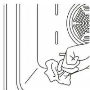
- Wipe the oven with a soft cloth soaked in soapy water
- Then wipe oven again with a wet cloth and dry it
natural_image
Line drawing of a hand cleaning a car window with a circular object on the wall (no text or symbols)CARE & MAINTENANCE
Cleaning the Gas Hob
- Clean the gas hob on a regular basis.
- Take off the pan supports, caps and crowns of the hob burners.
- Wipe the hob surface with a soft cloth soaked in soapy water. Then, wipe the hob surface over again with a wet cloth and dry it.
- Wash and rinse the hob-burner caps. Do not leave them wet. Dry them immediately with a dry cloth.
- Make sure you re-assemble all parts correctly after cleaning.
- The surfaces of the pan supports may become scratched over time due to use. This is not a production fault.
Cleaning Glass Parts
- Clean glass parts of your appliance on a regular basis
- Use a glass cleaner to clean the inside and outside of the glass parts
- Rinse and dry them thoroughly with a dry cloth
Cleaning the Enameled Parts
- Clean enameled parts of your appliance on a regular basis
- Wipe the enameled parts with a soft cloth soaked in soapy water
- Then wipe them over again with a wet cloth and dry them
IMPORTANT
Do not clean the enameled parts while they are still hot from cooking.
Do not leave vinegar, coffee, milk, salt, water, lemon, or tomato juice on the enamel for long periods of time.
Cleaning Stainless Steel Parts (if available)
- Clean stainless steel parts of your appliance on a regular basis
- Wipe the stainless steel parts with a soft cloth soaked in water only
- Then dry them thoroughly with a dry cloth
IMPORTANT
Do not clean the stainless steel parts while they are still hot from cooking
Do not leave vinegar, coffee, milk, salt, water, lemon, or tomato juice on the enamel for long periods of time
Cleaning Painted Surfaces (if available)
- Spots of tomato, tomato paste, ketchup, lemon, oil derivatives, milk, sugary foods, sugary drinks and coffee should be cleaned with a cloth dipped in warm water immediately
- If these are not cleaned and end up drying on the surfaces, they should not be rubbed with hard objects (pointed objects, steel and plastic scouring wires, surface-damaging dish sponge) or cleaning agents containing high levels of alcohol, stain removers, degreasers, surface abrasive chemicals. Otherwise, corrosion may occur on the powder painted surfaces, and stains can occur.
NOTE: The manufacturer will not be held responsible for any damage caused by the use of inappropriate cleaning products or methods
CARE & MAINTENANCE
Removal of the Inner Glass
You must remove the oven door glass before cleaning, as shown below:
- Push the glass in the direction of B and release from the location bracket (x). Pull the glass out in the direction of A.

To replace the inner glass:
- Push the glass towards and under the location bracket (y) in the direction of B.

- Place the glass under the location bracket (x) in the direction of C.

NOTE: If the oven door is a triple glass oven door, the third glass layer can be removed the same way as the second glass layer.
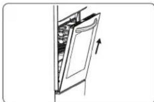
Removal of the Oven Door
NOTE: The oven door is removable but it is heavy. It is recommended that at least two people work together to remove it.
Remove the oven door before cleaning the oven door glass, as shown below:
- Open the oven door

natural_image
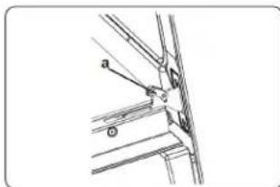
Technical line drawing of a mechanical assembly with an arrow indicating direction (no text or symbols)- Open the locking catch (a) (with the aid of a screwdriver) up to the end position.
natural_image
Technical line drawing of a mechanical assembly with labeled parts (a and b), no readable text or symbols present.- Close the door until it almost reaches the fully closed position and remove the door by pulling it towards you.
natural_image
Diagram of a door opening with a wall-mounted shelf and an arrow indicating direction (no text or symbols)Removal of the Wire Shelf
To remove the wire rack, pull the wire rack as shown in the figure. After releasing it from the clips (a), lift it up.

natural_image
Illustration of a hand interacting with a grid-like object on a laptop screen (no text or symbols visible)CARE & MAINTENANCE
Oven Light Replacement
Warning: The maintenance of this appliance should be carried out by an authorized service person or qualified technician only
Important
- Before replacing the oven light bulb, make sure the electrical power is disconnected from the appliance. Failure to do so may result in electric shock or burn
- Be sure to let the light cover and bulb cool completely before replacing
- Removing the oven door can make this process easier.
To replace the light bulb:
- Remove the glass lens, then remove the bulb
- Insert the new bulb (resistant to 572°F - 300 °C) to replace the bulb that you removed (110 V, 15-25 Watt, Type E14)
- Replace the glass lens, then your oven is ready to be used
Notes:
The product contains a light source of energy efficiency class G
The included light source is not intended for use in other applications - it is designed specifically for use in household cooking appliances. It is not suitable for household room illumination.
Other Controls
- Periodically check expiration date of the gas connection pipe.
- Periodically check the gas connection pipe. If a defect is found, contact an authorised service provider to have it changed.
- If a defect is found while operating the control knobs of the appliance, contact an authorised service provider.
| CARE & MAINTENANCE | |
| GENERAL | |
| Voltage / Frequency 110 - 120 V ~ 60 Hz | |
| Cable Type / Section / Length SJT 3x14 AWG / 5.25 ft | |
| Fuse Protection Min. 9A | |
| Gas Type / Pressure Natural Gas 5" / LP Gas 10" | |
| BURNERS | |
| Front Left Rapid Burner | |
| Power 11000 Btu/h - 11000 Btu/h | |
| Injector 1.55 mm - 0.96 mm | |
| Rear Left Semi Rapid Burner | |
| Power 8000 Btu/h - 8000 Btu/h | |
| Injector 1.18 mm - 0.82 mm | |
| Rear Right Semi Rapid Burner | |
| Power 8000 Btu/h - 8000 Btu/h | |
| Injector 1.18 mm - 0.82 mm | |
| Front Right Auxiliary Burner | |
| Power 3500 Btu/h - 3500 Btu/h | |
| Injector 0.90 mm - 0.55 mm | |
| Oven Burner Gas Thermostat Oven Burner | |
| Power 10000 Btu/h - 8500 Btu/h | |
| Injector 1.55 mm - 0.76 mm | |
| Total Power Consumption 40500 Btu/h - 39000 Btu/h | |
| Broil Electric Broiler | |
| Power 1000 W | |
| Inner Lamp 25 W | |
TROUBLESHOOTING
| Areas of Concern | Possible Cause Solutions | |
| Oven and/or grill (if available) do not work. | The oven and/or grill may be in the "off" position.Supply gas pressure may not be correct.Power (if the appliance has an electrical connection) is switched off.The feet have not been assembled.The battery (if applicable) may be depleted. | Check the position of the control knob.Check the gas supply and gas pressure.Check whether there is power supplied. Also check that other kitchen appliances are working.Make sure that there is no block at the bottom of the appliance.The battery may need replacing. |
| Oven is not cooking evenly. | Wrong shelf position being used.Your appliance has been installed by an unauthorised technician.Fan (if applicable) may be in the 'off' position. | Check the shelf positions, cooking period and heat values according to the manual.Check that the appliance is correctly installed.Ensure that the fan is working. |
| Oven temperature is too high or too low. | Wrong shelf position or wrong heat setting being used.Supply gas pressure may be improper. | Check that the recommended temperatures and shelf positions are being used. Be prepared to adjust the temperature up or down slightly to achieve the results you want.Check the gas supply and gas pressure. |
| Hob burners do not light • Burner cap and crown are not assembled correctly.Supply gas pressure may not be correct.LPG cylinder (if applicable) may be depleted.Power (if the appliance has an electric connection) is switched off.The battery (if applicable) may be depleted. | Ensure the burner parts have been placed correctly.Check the gas supply and gas pressure.LPG cylinder may need replacing.Check whether there is power supplied. Also check that other kitchen appliances are working.The battery may need replacing. | |
| Flame colour is orange/yellow. | Burner cap and crown are not assembled correctly.Different gas compositions. | Ensure the burner parts have been placed correctly.Due to the design of the burner, the flame can appear to be orange/yellow in certain areas of the burner.If you operate the appliance with natural gas, city natural gas may have different compositions.Do not operate the appliance for a couple of hours. |
| Burner is not igniting or only partially lighting. | Burner parts may not be clean or dry. • Ensure that parts of the appliance are dry and clean. | |
| Burner sounds noisy. | — | This is normal. The noise may reduce as they heat up. |
| Noise | — | It is normal for some metal parts on the cooker to produce noise when in use. |
| Oven light (if available) does not operate. | Lamp has failed.Electrical supply is disconnected or switched off. | Replace lamp according to the instructions.Make sure the electrical supply is switched on at the wall socket outlet. |
Danby.
Limited "In-Home" Warranty
This quality product is warranted to be free from manufacturer's defects in material and workmanship, provided that the unit is used under the normal operating conditions intended by the manufacturer. This warranty is available only to the person to whom the unit was originally sold by Danby Products Limited (Canada) or Danby Products Inc. (U.S.A.) (hereafter "Danby") or by an authorized distributor of Danby, and is non-transferable.
Terms of Warranty
Plastic parts are warranted for thirty (30) days from the date of purchase, with no extensions provided.
First 24 months
During the first twenty four (24) months, any functional parts of this product found to be defective, will be repaired or replaced, at warrantor's option, at no charge to the original purchaser.
To obtain service
Contact the dealer where the unit was purchased, or contact the nearest authorized Danby service depot, where service must be performed by a qualified service technician. If service is performed on the unit by anyone other than an authorized service depot, all obligations of Danby under this warranty shall be void.
Boundaries of in-home service
Danby reserves the right to limit the boundaries of "In Home Service" to the proximity of an authorized service depot. Any appliance requiring service outside the limited boundaries of "In Home Service", will be the consumer's responsibility to transport at their own expense to the original point of purchase or a service depot for repair. If the appliance is installed in a location that is 100 kilometers (62 miles) or more from the nearest service center, it must be delivered to the nearest authorized Danby Service Depot by the purchaser.
Transportation charges to and from the service location are not protected by this warranty and are the responsibility of the purchaser.
Exclusions
Save as herein provided, by Danby, there are no other warranties, conditions, representations or guarantees, express or implied, made or intended by Danby or its authorized distributors and all other warranties, conditions, representations or guarantees, including any warranties, conditions, representations or guarantees under any Sale of Goods Act or like legislation or statute is hereby expressly excluded. Save as herein provided, Danby shall not be responsible for any damages to persons or property, including the unit itself, howsoever caused or any consequential damages arising from the malfunction of the unit and by the purchase of the unit, the purchaser does hereby agree to indemnify and hold harmless Danby from any claim for damages to persons or property caused by the unit.
General Provisions
No warranty or insurance herein contained or set out shall apply when damage or repair is caused by any of the following:
- Power failure.
- Damage in transit or when moving the appliance.
- Improper power supply such as low voltage, defective house wiring or inadequate fuses.
- Accident, alteration, abuse or misuse of the appliance such as inadequate air circulation in the room or abnormal operating conditions (ie. extremely high or low room temperature).
- Use for commercial or industrial purposes (ie. If the appliance is not installed in a domestic residence).
- Fire, water damage, theft, war, riot, hostility, acts of God such as hurricanes, floods etc.
- Service calls resulting in customer education.
- Improper Installation (ie. Building-in of a free standing appliance or using an appliance outdoors that is not approved for outdoor application, including but not limited to: garages, patios, porches or anywhere that is not properly insulated or climate controlled).
Proof of purchase date will be required for warranty claims; retain bills of sale. In the event that warranty service is required, present the proof of purchase to our authorized service depot.
natural_image
Technical line drawing of a mechanical assembly with mounting brackets and fasteners (no text or symbols)

natural_image
Technical line drawing of a structural support bracket with mounting holes and a vertical guide (no text or symbols)Gas Natural (GN - Metano):
natural_image
Pure mechanical diagram showing a shaft and nut assembly with directional arrows (no text or symbols)natural_image
Pure mechanical component diagram without any text, numbers, or symbolsnatural_image
Simple line drawing of an electrical plug (no text or symbols)natural_image
Simple line drawing of a device with a screen and handle, no text or symbols presentCONTROL PANEL
Base circular de cacerola

natural_image
Two identical diagrams showing a cooking pot with crossed handles and a blank rectangular box containing 'X' symbols (no text or labels)natural_image
Line drawing of a mechanical component with a curved arrow indicating rotation (no text or symbols)natural_image
Technical line drawing of a curved panel or casing with an inset close-up showing internal components (no text or symbols)natural_image
Technical line drawing of a metal rack with a curved top panel and an arrow indicating rotation (no text or symbols)INSTRUCCIONES GENERALES DE LIMPIEZA
natural_image
Line drawing of a hand cleaning a car tire with a circular tire and tire ring (no text or symbols)natural_image
Technical line drawing of a mechanical assembly with an arrow indicating direction (no text or symbols)natural_image
Technical line drawing of a mechanical assembly with labeled parts (a, b, c) and no readable text or symbolsnatural_image
Diagram of a door opening with an arrow indicating direction (no text or symbols)natural_image
Illustration of a hand pressing down on a grid-like object with an arrow indicating direction (no text or symbols)Danby Products Limited, Guelph, Ontario, Canada N1H 6Z9 Danby Products Inc. Findlay, Ohio, U.S.A. 45840
www.danby.com
- OWNER'S MANUAL MANUAL DEL PROPIETARIO
- Welcome to the Danby family.
- Need Help?
- Important Safety Information READ AND FOLLOW ALL SAFETY INSTRUCTIONS
- WARNING
- IMPORTANT
- WARNING - TIP OVER HAZARD
- ANTI-TIP DEVICES
- ANTI-TIP BRACKET
- ANTI-TIP CHAIN
- INSTALL BOTH ANTI-TIP DEVICES
- SAVE THESE INSTRUCTIONS!
- GENERAL SAFETY REQUIREMENTS
- WARNING - FLAMMABLE MATERIALS
- WARNING - IN CASE OF FIRE
- COOKTOP SAFETY INSTRUCTIONS
- OVEN SAFETY INSTRUCTIONS
- INSTALLATION INSTRUCTIONS
- BEFORE INSTALLATION
- WARNING FOR INSTALLATION AND PREPARATION FOR USE
- INSTALLATION AND PREPARATION FOR USE
- INSTRUCTIONS FOR THE INSTALLER
- Ventilation requirements
- General instructions
- Installation of the Cooker
- Dimensions and Clearances
- GAS CONNECTION
- Assembly of gas supply and leakage check
- Points that must be checked during flexible hose assembly
- Points that must be checked during fixed gas connection assembly
- Gas Pressure Regulator
- GAS CONVERSION (IF AVAILABLE)
- Changing Pressure Setting of The Regulator
- Changing injectors Hob burners
- Electrical Connection and Safety
- OPERATING INSTRUCTIONS
- PRODUCT FEATURES
- CONTROL PANEL
- USE OF PRODUCT
- USE OF GAS BURNERS
- Ignition of the burners
- Manual ignition of the gas burners
- Electrical ignition by control knob
- Flame safety device
- Hob burners
- Oven / Grill (If available) Burners
- HOB CONTROLS
- Hob burner
- OVEN CONTROLS
- Oven Burner Controls
- Preheating
- Cooking
- Electric Grill Broiler
- Oven Lamp
- CARE & MAINTENANCE
- ACCESSORIES
- The Flap Drawer
- The Splashback
- GENERAL CLEANING INSTRUCTIONS
- Cleaning the Inside of the Oven
- Cleaning the Gas Hob
- Cleaning Glass Parts
- Cleaning the Enameled Parts
- Cleaning Stainless Steel Parts (if available)
- Cleaning Painted Surfaces (if available)
- Removal of the Inner Glass
- Removal of the Oven Door
- Removal of the Wire Shelf
- Oven Light Replacement
- To replace the light bulb:
- Notes:
- Other Controls
- Danby.
- Limited "In-Home" Warranty
- Terms of Warranty
- First 24 months
- To obtain service
- Boundaries of in-home service
- Exclusions
- General Provisions
- INSTRUCCIONES GENERALES DE LIMPIEZA
Brand : DANBY
Model : DR24V1WGLP
Category : Gas stove