
DTP DVI 4K 230 D Rx - Video Transmitter/Receiver Extron - Free user manual and instructions
Find the device manual for free DTP DVI 4K 230 D Rx Extron in PDF.


| Product Type | Video Receiver |
| Brand | Extron |
| Model | DTP DVI 4K 230 D Rx |
| Video Interface | DVI-D |
| Maximum Resolution | 4096x2160 at 30 Hz (4:4:4) |
| Color Depth | 8-bit, 10-bit, 12-bit |
| Audio Support | Embedded digital audio (LPCM) |
| Signal Type | DTP (Digital Twisted Pair) |
| Transmission Distance | Up to 330 ft (100 m) at 4K |
| EDID Management | Yes, with EDID Minder |
| HDCP Support | HDCP 2.3, HDCP 1.4 |
| Enclosure Type | Metal, half-rack width |
| Mounting | Rack-mountable, furniture-mountable |
| Power Supply | 12 V DC, 0.5 A, external |
| Power Consumption | 6 Watts (max) |
| Dimensions (H x W x D) | 1.7 in (4.3 cm) x 6.7 in (17.0 cm) x 3.3 in (8.4 cm) |
| Weight | 0.6 lbs (0.27 kg) |
| Operating Temperature | 32 to 104 °F (0 to 40 °C) |
| Storage Temperature | -40 to 158 °F (-40 to 70 °C) |
| Regulatory Compliance | CE, FCC Class A, c-UL, UL |
| Warranty | 3 years parts and labor |
Frequently Asked Questions - DTP DVI 4K 230 D Rx Extron
User questions about DTP DVI 4K 230 D Rx Extron
0 question about this device. Answer the ones you know or ask your own.
Ask a new question about this device
Download the instructions for your Video Transmitter/Receiver in PDF format for free! Find your manual DTP DVI 4K 230 D Rx - Extron and take your electronic device back in hand. On this page are published all the documents necessary for the use of your device. DTP DVI 4K 230 D Rx by Extron.
USER MANUAL DTP DVI 4K 230 D Rx Extron
DTP DVI 4K 230 D Series
DVI Twisted Pair Extender Transmitters and Receivers


Safety Instructions
Safety Instructions • English
WARNING: This symbol, , when used on the product, is intended to alert the user of the presence of uninsulated dangerous voltage within the product's enclosure that may present a risk of electric shock.
ATTENTION: This symbol, when used on the product, is intended to alert the user of important operating and maintenance (servicing) instructions in the literature provided with the equipment.
For information on safety guidelines, regulatory compliances, EMI/EMF compatibility, accessibility, and related topics, see the Extron Safety and Regulatory Compliance Guide, part number 68-290-01, on the Extron website, www.extron.com.
This equipment has been tested and found to comply with the limits for a Class A digital device, pursuant to part 15 of the FCC rules. The Class A limits provide reasonable protection against harmful interference when the equipment is operated in a commercial environment. This equipment generates, uses, and can radiate radio frequency energy and, if not installed and used in accordance with the instruction manual, may cause harmful interference to radio communications. Operation of this equipment in a residential area is likely to cause interference. This interference must be corrected at the expense of the user.
ATTENTION: The Twisted Pair Extension technology works with unshielded twisted pair (UTP) or shielded twisted pair (STP) cables; but to ensure FCC Class A and CE compliance, STP cables and STP Connectors are required.
For more information on safety guidelines, regulatory compliances, EMI/EMF compatibility, accessibility, and related topics, see the “Extron Safety and Regulatory Compliance Guide” on the Extron website.
Conventions Used in this Guide
Notifications
The following notifications are used in this guide:
WARNING: Potential risk of severe injury or death.
CAUTION: Risk of minor personal injury.
NOTE: A note draws attention to important information.
Copyright
© 2017 Extron Electronics. All rights reserved.
Trademarks
All trademarks mentioned in this guide are the properties of their respective owners.
The following registered trademarks ® , registered service marks (SM) , and trademarks (TM) are the property of RGB Systems, Inc. or Extron Electronics (see the current list of trademarks on the Terms of Use page at www.extron.com):
| Registered Trademarks ® |
| Extron, Cable Cubby, ControlScript, CrossPoint, DTP, eBUS, EDID Manager, EDID Minder, Flat Field, FlexOS, Global Configurator, Global Scripter, GlobalViewer, Hideaway, IP Intercom, IP Link, Key Minder, LinkLicense, LockIt, MediaLink, MediaPort, NetPA, PlenumVault, PoleVault, PowerCage, PURE3, Quantum, SoundField, SpeedMount, SpeedSwitch, System INTEGRATOR, TeamWork, TouchLink, V-Lock, VN-Matrix, VoiceLift, WallVault, WindoWall, XTP, and XTP Systems |
| Registered Service Mark SM : S3 Service Support Solutions |
| Trademarks TM |
| AAP, AFL (Accu-Rate Frame Lock), ADSP (Advanced Digital Sync Processing), Auto-Image, CableCover, CDRS (Class D Ripple Suppression), DDSP (Digital Display Sync Processing), DMI (Dynamic Motion Interpolation), Driver Configurator, DSP Configurator, DSVP (Digital Sync Validation Processing), eLink, Entwine, EQIP, EverLast, FastBite, FOX, FOXBOX, HyperLane, IP Intercom HelpDesk, MAAP, MicroDigital, Opti-Torque, ProDSP, QS-FPC (QuickSwitch Front Panel Controller), Room Agent, Scope-Trigger, ShareLink, Show Me, SIS, Simple Instruction Set, Skew-Free, SpeedNav, StudioStation, Triple-Action Switching, True4K, Vector TM 4K , VideoLounge, WebShare, XTRA, ZipCaddy, and ZipClip |
Contents
Introduction ...... 1
About this Guide....1
About the DTP DVI 4K 230 D Extenders....1
Twisted Pair Cable Advantages....2
Transmission Distance 2
Features 2
Installation and Operation 3
Mounting the Transmitter or Receiver......3
UL and Safety Guidelines....3
Preparing the Site and Installing the Wall Box....3
Installing a Mud Ring 5
Final Installation 6
Transmitter Connections....6
Transmitter Front Panel....6
Transmitter Rear Panel....7
Receiver Connections......8
Receiver Rear Panel 8
Receiver Front Panel....9
Connector and Cable Details....10
TP Cable Termination and Recommendations .... 10
Power Supply Wiring 11
RS-232 and IR Connector Wiring 13
Operation 13
Transmitter Power Indicator 13
Receiver Power Indicator 13
System Operation....14
Ground Loops 15
Reference Information ......16
Decorator-Style Wallplate Template Dimensions 16
Introduction
• About this Guide
• About the DTP DVI 4K 230 D Extenders
- Features
About this Guide
This guide describes the Extron DTP DVI 4K 230 D family of Digital Visual Interface (DVI) Extenders, which consists of the DTP DVI 4K 230 D Tx and DTP DVI 4K 230 D Rx. This guide describes how to install, operate, and configure them.
About the DTP DVI 4K 230 D Extenders
The Extron DTP DVI 4K 230 D extenders are a family of DVI transmitters and receivers (see figure 1) which are housed in enclosures that can be mounted in Underwriters Laboratories (UL) standard wall boxes with decorator-style wallplates. A transmitter and receiver pair extends the usable distance of DVI digital video and RS-232 or IR control signals over one Category (CAT) 5e, 6, 6a, or 7 unshielded twisted pair (UTP) or shielded twisted pair (STP) cable. The DTP DVI 4K 230 D transmitter and receiver also route audio. The video, control, and audio (if applicable) signals can be transmitted up to 230 feet (70 m).
![graph TD A["Extron DTP DVI 4K 230 D Tx\nDVI Twisted Pair Extender"] --> B["PC"] A --> C["RS-232"] C --> D["Extron DTP DVI 4K 230 D Rx\nDVI Twisted Pair Extender"] C --> E["RP"] E --> F["Projector"] G["TCP/IP"] --> H["TouchLink Control System"] H --> I["Data Bus"] style A fill:#f9f,stroke:#333 style…](/content/2026/06/1249815/images/39e48fb9472b692ed629fba072d6d2835bb2c3586629b178e793d9bc21b21375.jpg)
Figure 1. Typical Transmitter and Receiver Application
A DTP DVI 4K 230 D system consists of a transmitter (Tx) and a receiver (Rx). The pair can handle a single link of DVI-D digital video and a bidirectional RS-232 or IR link.
The DTP DVI 4K 230 D transmitter and receiver are sold separately. Each transmitter is shipped with a single external desktop 12 VDC power supply that accepts 100 to 240 VAC, 50-60 Hz input. A single power supply connected to either the transmitter or the receiver can power both units through the twisted pair cable that links the units.
Twisted Pair Cable Advantages
Twisted pair cable is much smaller, lighter, more flexible, and less expensive than coaxial or DVI cable. These transmitter and receiver twisted pair (TP) products make cable runs simpler and less cumbersome. Termination of the cable with RJ-45 connectors is simple, quick, and economical.
NOTE: Do not use Extron UTP23SF-4 Enhanced Skew-Free AV UTP cable or STP201 cable to link the transmitter and receiver. The DTP DVI 4K 230 Tx/Rx does not work properly with these cables.
Transmission Distance
The maximum transmission distance is determined by the resolution of the signal and the twisted pair cable that is used.
Features
- Transmits single link DVI-D plus control and analog audio up to 230 feet (70 meters) over a shielded CATx cable
• Supports DDC and HDCP copy protection transmission — The transmitter and receiver pair fully supports long distance transmission of the DDC and HDCP signals. - Control communications pass-through — Bidirectional RS-232 or IR control signals can be transmitted alongside the DVI signal, so that the remote display can be controlled without the need for additional cabling.
- Audio routing — The DTP DVI 4K 230 D transmitter and receiver also route unbalanced stereo audio.
• Supports CEC signal transmission
• Wall-mountable enclosures - External 100 VAC to 240 VAC, 50-60 Hz, international power supply — Included with transmitters.
- Remote powering of transmitter or receiver — Only one power supply is necessary to power both devices.
Installation and Operation
This section describes the installation and the operation of the DTP DVI 4K 230 D transmitter and receiver, including:
- Mounting the Transmitter or Receiver
• Transmitter Connections
• Receiver Connections - Connector and Cable Details
• Power Supply Wiring
• RS-232 and IR Connector Wiring - Operation
- Ground Loops
Mounting the Transmitter or Receiver
ATTENTION:
The DTP DVI 4K 230 D transmitter and receiver can be installed in a two-gang electrical wall box or with a mud ring, with a decorator-style wallplate cover (supplied).
The installation must conform to national and local electrical codes and to the size requirements of the wall plate.
UL and Safety Guidelines
The following UL guidelines pertain to the installation of the decorator-style wallplate transmitters and receivers into a wall or furniture.
- These units are not to be connected to a centralized DC power source or used beyond their rated voltage range.
• These units must be installed in UL-listed junction boxes.
• These units must be installed with conduit in accordance with National Electrical Code.
Preparing the Site and Installing the Wall Box
Choose a location that allows cable runs without interference. Allow enough depth for both the wall box and the cables. The box should be at least 3.0 inches (7.6 cm) deep to accommodate the connectors and cables. Install the cables into the wall, furniture, or conduits before installing the wall plate.
NOTE: The decorator-style wallplate units are very deep and have connectors on the back side. Extron recommends a 2-gang junction box which has a depth of 3.0 inches (7.6 cm).
To install a new wall box, perform steps 1 through 9. If a suitable wall box is already installed, perform steps 6 through 9 on the next page. UL listed wall boxes are recommended.
-
If a wall box is not available to use for a template, see Decorator-Style Wallplate Template Dimensions on page 16 to create a template. If installing directly into furniture, cut out the center portion of your template.
-
Place the wall box (or your template) against the installation surface, and mark the opening guidelines.
-
Cut out the material from the marked area.
-
Insert the wall box into the opening. The rear connectors on the box or wall plate should fit easily into the opening. Enlarge or smooth the edges of the opening if needed.
-
Secure the wall box with nails or screws, leaving the front edge flush with the outer wall or furniture surface (see figure 2).
NOTES:
- If attaching the wall box to wood, use four #8 or #10 screws or 10-penny nails. A minimum of 0.5 inch (1.3 cm) of screw thread must penetrate the wood.
- If attaching the wall box to metal studs or furniture, use four #8 or #10 self-tapping sheet metal screws or machine bolts with matching nuts.
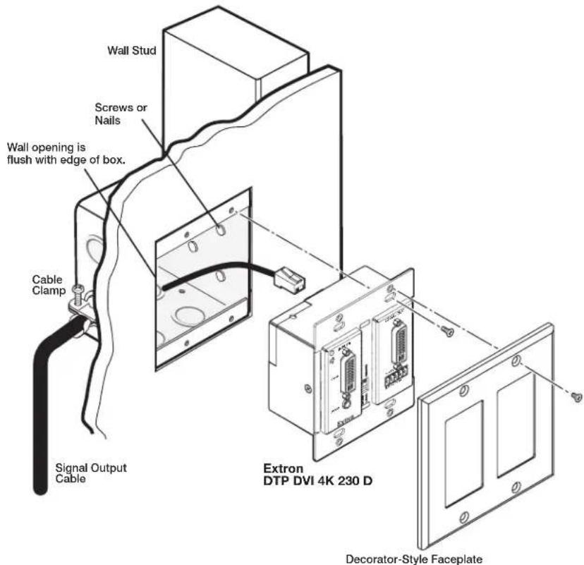
Figure 2. Installing the Wall Box and Mounting the Unit
- Feed the twisted pair cables and the power cables through the opening and through the wall box punch-out holes, securing them with cable clamps to provide strain relief.
NOTES:
- In order to fit in the junction box, the twisted pair cables and RJ-45 connectors should not have a boot installed.
-
One power supply can power both the transmitter and the receiver (see Power Supply Wiring on page 11 and Ground Loops on page 15).
-
Trim back and insulate exposed cable shields with heat shrink to reduce the chance of short circuits.
To prevent short circuits, the outer foil shield can be cut back to the point where the cable exits the cable clamp.
-
Connect the cables to the rear of the unit (see Transmitter Rear Panel on page 7 and Receiver Rear Panel on page 8 for connector details).
-
Connect front panel devices (see Transmitter Front Panel on page 6 and Receiver Front Panel on page 9 for connector details), restore the power supply, and test the transmitter and receiver system. Make any cabling adjustments before final installation, as the cables will be inaccessible afterwards.
Installing a Mud Ring
- Using the mud ring as a guide, mark the edges and cut out the material within the marked area.
- Insert the mud ring into the opening, rotate and secure the locking arms with the supplied screws shown in figure 3.
- Follow steps 6 through 9 of Preparing the Site and Installing the Wall Box above, and Final Installation on the next page.
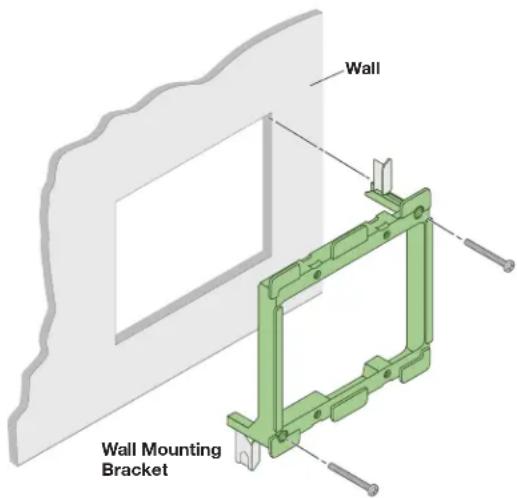
Figure 3. Installing the Mud Ring
Final Installation
After testing and making any adjustments, do the following:
- At the power outlet, unplug the power supply.
NOTE: One power supply can power both the transmitter and the receiver (see Power Supply Wiring on page 11 and Ground Loops on page 15).
- Mount the transmitter or receiver into the wall box or mud ring, and attach the supplied decorator-style faceplate to the unit, as shown in figure 2 on page 4.
- At the power outlet, reconnect the power supply. This powers up both units.
Transmitter Connections
The DTP DVI 4K 230 D transmitter is in an enclosure that can be mounted in UL-listed standard wall boxes with decorator-style face plates.
Transmitter Front Panel
Figure 4 shows the front panel of the DTP DVI 4K 230 D transmitter.

Figure 4. DTP DVI 4K 230 D Transmitter Front Panel Connectors
A DVI input connector — Connect a DVI cable between this port and the DVI output port of the digital video source.
B Local Out connector — Connect a DVI cable between this port and the DVI input of a local monitor.
NOTE: In a system where the local output is not used, ensure that you power up the end display before the video source. Route the DDC to the remote end (see ⑤ on the next page).
Audio input — Connect an unbalanced stereo audio source to this 3.5 mm mini stereo jack for unbalanced audio input. Figure 5 shows how to wire the audio plug.

Figure 5. Audio Input Connector Wiring
D RS-232 and IR (Control) pass-through connector — Connect a serial communications port to this 3.5 mm, 5-pole captive screw connector for bidirectional RS-232 communication and IR communication (see RS-232 and IR Connector Wiring on page 13 to wire the connector).
E DDC Route switch — This switch selects either the remote or local DVI display as the Display Data Channel (DDC) reference for EDID and HDCP communication.
Transmitter Rear Panel

Figure 6. DTP DVI 4K 230 D Transmitter Rear Panel Connectors
A DC power input connector — Plug the included external 12 VDC power supply into either this 2-pole connector or the power input connector on the receiver (see Power Supply Wiring on page 11 to wire the connector).
B Transmitter output port — Connect one end of a twisted pair cable to this RJ-45 output port.
ATTENTION:
Connect the opposite end of the twisted pair cable to the receiver input port shown in figure 7 (see TP Cable Termination and Recommendations on page 10 to properly wire the RJ-45 connectors).
NOTES:
- In order to fit in the junction box, the twisted pair cables and RJ-45 connectors should not have a boot installed.
- Do not use Extron STP201 or Skew-Free UTP series cable with these products
Receiver Connections
The DTP DVI 4K 230 D receiver is in an enclosure that can be mounted in UL-listed standard wall boxes with decorator-style face plates.
Receiver Rear Panel
Figure 7 shows the rear panel of the DTP DVI 4K 230 D receiver.
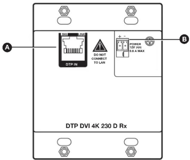
Figure 7. DTP DVI 4K 230 D Receiver Rear Panel Connectors
A Receiver input port — Connect one end of a twisted pair cable to this RJ-45 input port.
ATTENTION:
Connect the opposite end to the RJ-45 output (see figure 7 above) on the transmitter (see TP Cable Termination and Recommendations on page 10 to properly wire the RJ-45 connectors).
NOTES:
- In order to fit in the junction box, the twisted pair cables and RJ-45 connectors should not have a boot installed.
- Do not use Extron STP201 or Skew-Free UTP series cable with these products
B DC power input connector — Plug the included external 12 VDC power supply into either this 2-pole connector or the power input connector on the receiver (see Power Supply Wiring on page 11 to wire the connector).
Receiver Front Panel
Figure 8 shows the front panel of the DTP DVI 4K 230 D receiver.

Figure 8. DTP DVI 4K 230 D Receiver Front Panel Connectors
A DVI output connector — Connect a DVI display for the transmitted direct digital image.
B Audio output connector — Connect a stereo audio device to this 3.5 mm mini stereo jack to receive the unbalanced audio output (see figure 5 on page 7 to wire the audio connector).
RS-232 and IR (Control) pass-through connector — Connect a serial communications port to this 3.5 mm, 5-pole captive screw connector for bidirectional RS-232 communication and IR communication (see RS-232 and IR Connector Wiring on page 13 to wire the connector).
Connector and Cable Details
TP Cable Termination and Recommendations
Figure 9 details the recommended termination of both ends of TP cables with RJ-45 connectors in accordance with the TIA/EIA T 568B wiring standard.

Figure 9. TP Cable Termination
NOTE: Do not use Extron UTP23SF-4 Enhanced Skew-Free AV UTP cable or STP201 cable to link the transmitter and receiver. The DTP DVI 4K 230 D Tx/Rx does not work properly with these cables.
Supported cables —
The DTP DVI 4K 230 D is compatible with CAT 5e, 6, 6a, and 7 shielded twisted pair (F/UTP, SF/UTP, and S/FTP) and unshielded twisted pair (U/UTP) cable.
Cable recommendations —
Extron recommends using the following practices to achieve full transmission distances up to 230 feet (70 m) and reduce transmission errors.
- Use the following Extron XTP DTP 24 SF/UTP cables and DTP 24 connectors for the best performance:
-
XTP DTP 24/1000 Non-Plenum 1000' (305 m) spool 22-236-03
• XTP DTP 24P/1000 Plenum 1000' (305 m) spool 22-235-03
• XTP DTP 24 Plug Package of 10 101-005-02 -
If not using XTP DTP 24 cable, at a minimum, Extron recommends 24 AWG, solid conductor, STP cable with a minimum bandwidth of 400 MHz.
- Terminate cables with shielded connectors to the TIA/EIA T 568 B standard.
- Use no more than two pass-through points, which may include patch points, punch down connectors, couplers, and power injectors. If pass-through points are required, use CAT 6 or 6a shielded couplers and punch down connectors.
NOTE: When using CAT 5e and CAT 6 cable in bundles or conduits, consider the following:
- Do not exceed 40% fill capacity in conduits.
- Do not comb the cable for the first 20 meters, where cables are straightened, aligned, and secured in tight bundles.
- Loosely place cables and limit the use of tie wraps or Velcro®.
- Separate twisted pair cables from AC power cables.
Power Supply Wiring
NOTES:
- Only one power supply is required. A single power supply connected to either unit in the pair powers both units (see Ground Loops on page 15).
- A power supply is included with each individually-packaged transmitter.
Figure 10 shows how to wire the connector. Snap the provided ferrite bead onto the DC power cable, between the power supply and the connector on the DVI unit.

Figure 10. Power Connector Wiring
CAUTION: Risk of minor personal injury.
- Always use a power supply supplied and or specified by Extron. Use of an unauthorized power supply voids all regulatory compliance certification and may cause damage to the supply and the end product.
- If not provided with a power supply, this product is intended to be supplied by a power source marked "Class 2" or "LPS" and rated at 12 VDC and a minimum of 1.0 A.
- The installation must always be in accordance with the applicable provisions of National Electrical Code ANSI/NFPA 70, article 725 and the Canadian Electrical Code part 1, section 16. The power supply shall not be permanently fixed to building structure or similar structure.
- Power supply voltage polarity is critical. Incorrect voltage polarity can damage the power supply and the unit. The ridges on the side of the cord (see figure 10 on previous page) identify the power cord negative lead.
- To verify the polarity before connection, plug in the power supply with no load and check the output with a voltmeter.
- The length of the exposed (stripped) copper wires is important. The ideal length is 3/16 inch (5 mm). Longer bare wires can short together. Shorter wires are not as secure in the connectors and could be pulled out.
- Unless otherwise stated, the AC/DC adapters are not suitable for use in air handling spaces or in wall cavities.
NOTE: Do not tin the power supply leads before installing them in the direct insertion connector. Tinned wires are not as secure in the connectors and could be pulled out.
RS-232 and IR Connector Wiring
Figure 11 shows how to wire the RS-232 and IR connector for the DTP DVI 4K 230 D units.
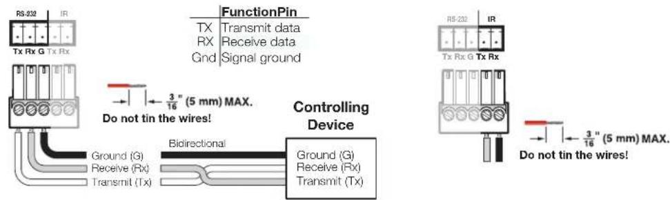
Figure 11. RS-232 and IR Connector Wiring
Operation
Figure 12 shows the power indicator on the decorator-style wallplate transmitter.
NOTE: Both transmitter and receiver have power indicators on the front panel.

Figure 12. DTP DVI 4K 230 D Power Indicator
Transmitter Power Indicator
Power LED — This two-color front panel LED lights to indicate signal and power status as follows:
- Amber — The unit is receiving power but no signal on the DVI input.
- Green — The unit is receiving power and a signal is present on the DVI input.
Receiver Power Indicator
B Power LED — This two-color front panel LED lights to indicate signal and power status as follows:
- Amber — The unit is receiving power but no signal on the TP input.
- Green — The unit is receiving power and a signal is present on the TP input.
System Operation
After the transmitter, the receiver, and their connected devices are powered up, the system is fully operational. If any problems are encountered, ensure all cables are routed and connected properly.
NOTE: Ensure that the video source and display selected for the DDC are properly connected to the transmitter and receiver pair, and that the transmitter, the receiver, and the display have power applied before power is applied to the video source. If all other devices are not turned on before the video source, the image may not appear.
Ground Loops
When installing the DTP DVI 4K 230 D series products, be sure to avoid scenarios where the ground potential differs greatly between the locations where the DTP transmitter and DTP receiver are installed. Such situations can cause ground loops, which can result in image drops, no image, or damage to the units. If such installations cannot be avoided, it is necessary to isolate the ground between the DTP transmitter and receiver.
NOTES:
- Grounding DTP series units will disable analog audio transmission and the remote power feature.
- Both DTP transmitter and receiver will need to be powered locally.
To eliminate a ground loop:
- Remove all screws on the left, right, and top of both the DTP transmitter and receiver units.
- Remove the rear enclosure of each unit.
- Locate and remove shunt jumpers at locations labeled JMP2 and JMP3 on both transmitter and receiver (see figure 13 for jumper locations).
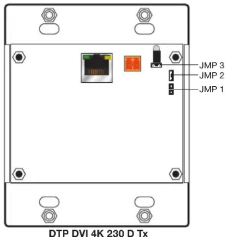

Figure 13. DTP DVI 4K 230 D Internal Jumper Locations
- Replace the rear enclosures and screws.
- Install units with an external power supply placed at each end.
- Use UTP cable between the DTP transmitter and receiver. If STP cable has already been installed and terminated, disconnect the shielding at one end to discontinue the ground path.
Reference Information
This section includes decorator-style wallplate template dimensions for installation of the DTP DVI 230 D transmitters and receivers.
Decorator-Style Wallplate Template Dimensions
If you need to create a template, use the dimensions shown on figure 14.
NOTES:
- The drawing is not full size or to scale. DO NOT scale up or print to use as a template.
• Full size templates are available online at www.extron.com.
Template for the 2-gang mounting bracket

Figure 14. Decorator-Style Wallplate Template Dimensions
Extron Warranty
Extron Electronics warrants this product against defects in materials and workmanship for a period of three years from the date of purchase. In the event of malfunction during the warranty period attributable directly to faulty workmanship and/or materials, Extron Electronics will, at its option, repair or replace said products or components, to whatever extent it shall deem necessary to restore said product to proper operating condition, provided that it is returned within the warranty period, with proof of purchase and description of malfunction to:
USA, Canada, South America, and Central America:
Extron Electronics
1230 South Lewis Street
Anaheim, CA 92805
U.S.A.
Europe and Africa:
Extron Europe
Hanzeboulevard 10
3825 PH Amersfoort
The Netherlands
Asia:
Extron Asia Pte Ltd
135 Joo Seng Road, #04-01
PM Industrial Bldg.
Singapore 368363
Singapore
Japan:
Extron Electronics, Japan
Kyodo Building, 16 Ichibancho
Chiyoda-ku, Tokyo 102-0082
Japan
China:
Extron China
686 Ronghua Road
Songjiang District
Shanghai 201611
China
Middle East:
Extron Middle East
Dubai Airport Free Zone
F13, PO Box 293666
United Arab Emirates, Dubai
This Limited Warranty does not apply if the fault has been caused by misuse, improper handling care, electrical or mechanical abuse, abnormal operating conditions, or if modifications were made to the product that were not authorized by Extron.
NOTE: If a product is defective, please call Extron and ask for an Application Engineer to receive an RA (Return Authorization) number. This will begin the repair process.
USA: 714.491.1500 or 800.633.9876
Europe: 31.33.453.4040
Asia: 65.6383.4400
Japan: 81.3.3511.7655
Units must be returned insured, with shipping charges prepaid. If not insured, you assume the risk of loss or damage during shipment. Returned units must include the serial number and a description of the problem, as well as the name of the person to contact in case there are any questions.
Extron Electronics makes no further warranties either expressed or implied with respect to the product and its quality, performance, merchantability, or fitness for any particular use. In no event will Extron Electronics be liable for direct, indirect, or consequential damages resulting from any defect in this product even if Extron Electronics has been advised of such damage.
Please note that laws vary from state to state and country to country, and that some provisions of this warranty may not apply to you.
| Extron Headquarters+1.800.633.9876 (Inside USA/Canada Only)Extron USA - West Extron USA - East+1.714.491.1500 +1.919.850.1000+1.714.491.1517 FAX +1.919.850.1001 FAX | Extron Europe+800.3987.6673(Inside Europe Only)+31.33.453.4040+31.33.453.4050 FAX | Extron Asia+65.6383.4400+65.6383.4664 FAX | Extron Japan+81.3.3511.7655+81.3.3511.7656 FAX | Extron China+86.21.3760.1568+86.21.3760.1566 FAX | Extron Middle East+971.4.299.1800+971.4.299.1880 FAX | Extron Australia+61.8.8113.6800+61.8.8351.2511 FAX | Extron India1800.3070.3777(Inside India Only)+91.80.3055.3777+91.80.3055.3737 FAX |
- DTP DVI 4K 230 D SERIES
- SAFETY INSTRUCTIONS
- SAFETY INSTRUCTIONS • ENGLISH
- CONVENTIONS USED IN THIS GUIDE
- NOTIFICATIONS
- COPYRIGHT
- TRADEMARKS
- CONTENTS
- INTRODUCTION ...... 1
- INSTALLATION AND OPERATION 3
- REFERENCE INFORMATION ......16
- INTRODUCTION
- ABOUT THIS GUIDE
- ABOUT THE DTP DVI 4K 230 D EXTENDERS
- TWISTED PAIR CABLE ADVANTAGES
- TRANSMISSION DISTANCE
- FEATURES
- INSTALLATION AND OPERATION
- MOUNTING THE TRANSMITTER OR RECEIVER
- ATTENTION
- UL AND SAFETY GUIDELINES
- PREPARING THE SITE AND INSTALLING THE WALL BOX
- NOTES
- INSTALLING A MUD RING
- FINAL INSTALLATION
- TRANSMITTER CONNECTIONS
- TRANSMITTER FRONT PANEL
- RECEIVER CONNECTIONS
- RECEIVER REAR PANEL
- RECEIVER FRONT PANEL
- CONNECTOR AND CABLE DETAILS
- TP CABLE TERMINATION AND RECOMMENDATIONS
- SUPPORTED CABLES
- CABLE RECOMMENDATIONS
- POWER SUPPLY WIRING
- RS-232 AND IR CONNECTOR WIRING
- OPERATION
- TRANSMITTER POWER INDICATOR
- RECEIVER POWER INDICATOR
- SYSTEM OPERATION
- GROUND LOOPS
- REFERENCE INFORMATION
- DECORATOR-STYLE WALLPLATE TEMPLATE DIMENSIONS
- EXTRON WARRANTY
- USA, CANADA, SOUTH AMERICA, AND CENTRAL AMERICA
- EUROPE AND AFRICA
- ASIA
- JAPAN
- CHINA
- MIDDLE EAST
Brand : Extron
Model : DTP DVI 4K 230 D Rx
Category : Video Transmitter/Receiver