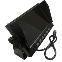
CTR-W7 - Security Camera CRUX - Free user manual and instructions
Find the device manual for free CTR-W7 CRUX in PDF.


| Product Type | Security Camera |
| Brand | CRUX |
| Model | CTR-W7 |
| Dimensions (L x W x H) | 6.3 x 2.9 x 2.8 inches (160 x 74 x 71 mm) |
| Weight | 0.9 lbs (400 g) |
| Power Supply | 12V DC, 1A (adapter included) |
| Video Resolution | 1080p Full HD (1920 x 1080) |
| Field of View | 90° wide angle |
| Night Vision | Up to 30 ft (10 m) with IR LEDs |
| Weatherproof Rating | IP65 (indoor/outdoor use) |
| Connectivity | Wired (BNC/RCA composite video) |
| Mounting Type | Wall or ceiling mount with bracket |
| Motion Detection | Yes, adjustable sensitivity |
| Audio | Built-in microphone (mono audio) |
| Storage | Compatible with DVR/NVR (not included) |
| Operating Temperature | -4°F to 122°F (-20°C to 50°C) |
| Maintenance | Clean lens with soft dry cloth; avoid solvents |
| Safety | Use only supplied power adapter; do not expose to rain |
| Spare Parts & Repairability | Contact CRUX support for replacement cables or brackets |
| General Information | Manual available in PDF at notice-facile.com |
Frequently Asked Questions - CTR-W7 CRUX
User questions about CTR-W7 CRUX
0 question about this device. Answer the ones you know or ask your own.
Ask a new question about this device
Download the instructions for your Security Camera in PDF format for free! Find your manual CTR-W7 - CRUX and take your electronic device back in hand. On this page are published all the documents necessary for the use of your device. CTR-W7 by CRUX.
USER MANUAL CTR-W7 CRUX
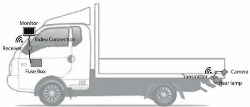
Use on trucks, SUVs, RVs, Buses and other vehicles that require wireless reverse camera solution.
PRODUCT FEATURES:
WIRELESS CAMERA
- 2.4 GHz, 20 Channel Frequency Hopping Method for clear image.
- 120° effective viewing angle.
- 8 IR LEDs for up to 10M visibility at night.
- Waterproof camera and transmitter (IP 69K).
MONITOR
- 16:9 Wide Screen LCD Monitor with removable sunshade.
- 2 camera inputs.
- Separate trigger control wire with automatic switch over for each camera.
- Adjustable parking guide lines generated by monitor.
- Stainless Steel Aviation connectors.
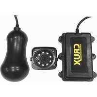
PARTS INCLUDED:

natural_image
Close-up of a black mechanical component with mounting flanges and central hub (no visible text or symbols)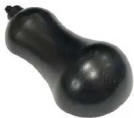
natural_image
Black gourd-shaped object with smooth surface and small protrusions (no text or symbols)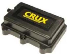
natural_image
Black CRUX electrical contact box with visible mounting holes and gold branding (no text or symbols on body)Wireless Camera Receiver Transmitter

natural_image
Black rectangular electronic device with a coiled cable, no visible text or symbols
natural_image
Coiled black cable with connectors and connectors, no visible text or symbols
natural_image
Coiled black and red audio/video cables with a yellow connector (no text or symbols visible)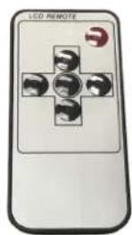
7" Monitor Power/Video Harness
4 pin to RCA Adatper (2 pcs)
Remote Control
INSTALLATION INSTRUCTIONS:

natural_image
Close-up of a red vehicle chassis with four circular vent holes and mounting brackets (no visible text or symbols)- Find a suitable location to install the camera. 2. Test fit the bracket to make sure theres is enough space.

natural_image
Close-up of a hand inserting a small component into a black plastic housing (no text or symbols visible)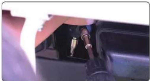
natural_image
Close-up of a mechanical component with a metallic connector inserted into a black housing (no visible text or symbols)- Use the screws provided to mount the bracket. 4. Install the camera to the bracket. Do not completely tighten the screws yet.
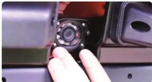
natural_image
Close-up of a hand holding a camera module with a small inset image (no visible text or symbols)
natural_image
Close-up of a mechanical component with a circular button and mounting holes (no visible text or symbols)- Above is how the camera should be installed. 6. Mount the transmitter no more than 3 feet from the camera

natural_image
Person kneeling beside a dark concrete beam, viewed from the side (no text or symbols visible)
natural_image
Close-up of a dark, textured object being cut with a tool, no visible text or symbols- Clean the surface where the transmitter will be mounted.

natural_image
Hand holding a dark blue grid-patterned device with two white circular holes, surrounded by wires and tools (no visible text or symbols)- Attach the double sided adhesive to the transmitter.

natural_image
Close-up of hands holding a black rectangular object with a small protrusion, placed on a tiled surface (no visible text or symbols)- Press down on the transmitter to adhere to the surface.

natural_image
Close-up of a black electrical component with two gold pins, against a textured purple background (no visible text or symbols)- Attach the "L" brackets using the screws provided.

natural_image
Close-up of a black electrical contactor with gold pins, mounted on a textured surface (no visible text or symbols)- Use cable ties to securely fasten the transmitter. 12.
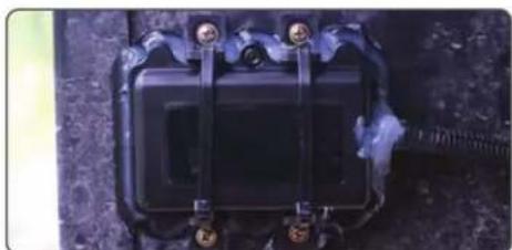
natural_image
Close-up of a black electrical contactor with metal clamps and mounting feet (no visible text or symbols)We recommend putting silicone sealant around the base of the transmitter to prevent dirt from going behind the transmitter.

natural_image
Close-up of a black electrical connector with a red wire and green indicator symbol (no text or symbols visible)- Disconnect the reverse light connector. 14. Strip the

natural_image
Close-up of hands using red power probes to inspect a cable or wire component (no visible text or symbols)power and ground wires of the reverse light.
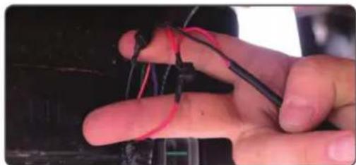
natural_image
Close-up of a hand holding wires with black and red connectors, no visible text or symbols- Tap the red and black wires of the CTR-01Q camera cable to the positive and negative wires.

natural_image
Close-up of a mechanical component with a coiled spring and mounting holes (no visible text or symbols)- Reconnect the reverse light connector.

natural_image
Close-up of hands installing a black cable connector into a car body panel using a drill pen (no visible text or symbols)- Organize the cables using zip ties and cable clamps.

natural_image
Close-up of a hand holding a black cable with yellow connectors, against a blue textured background (no text or symbols visible)- Connect receiver's red wire to ACC and black wire to ground. Plug the Yellow video RCA to the monitor (not included).
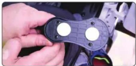
natural_image
Close-up of hands holding a black plastic device with two white circular buttons, no visible text or symbols- Attach the double sided adhesive tape under the receiver. Do not remove the bottom liner of the double sided tape yet.
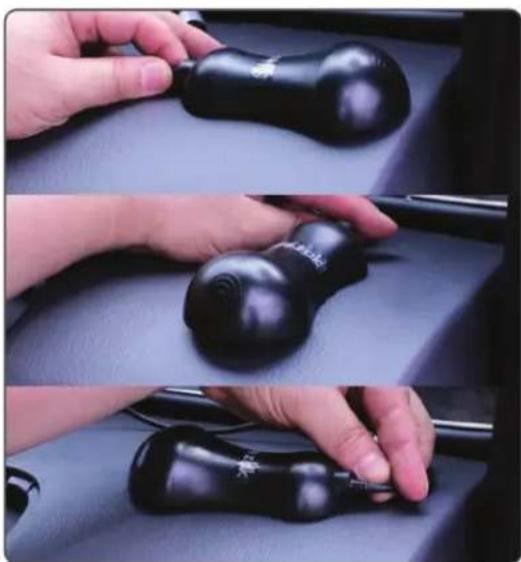
natural_image
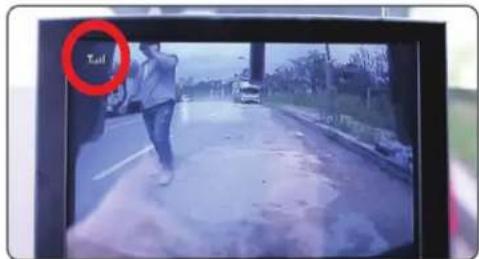
Three-panel photo showing hands holding black ergonomic devices on a dark surface, no visible text or symbols- With the ignition turned to ACC, put the vehicle in reverse. Turn on the monitor and find the best direction for the receiver turning it until you see atleast 3 bars on the monitor.
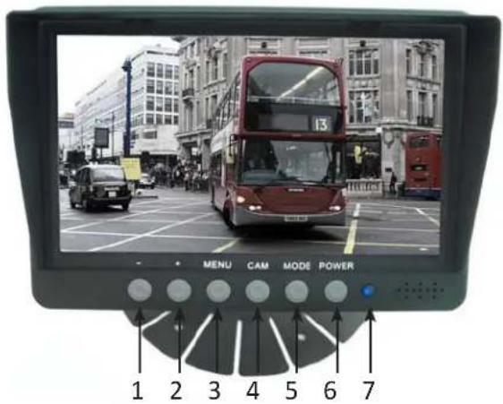
MONITOR:
(1) Down Button
(2) Up Button
(3) Menu
(4) Camera Source Button
(5) Mode Button
(6) Power Switch
(7) Power indicator
REMOTE CONTROL:

(1) Camera Source
(2) Down Button
(3) Menu
(4) Power Button
(5) Up Button
(6) Mode Button
4-PIN HARNESS:

(1) Reverse Gear Trigger (Green)
(2) Ground (Black)
(3) Power Wire (12V or 24V) Red
(4) Camera 1 Input
(5) Camera 2 Input
(6) Video Output to Monitor
PAIRING THE TRANSMITTER TO THE RECEIVER:
The transmitter and receiver are already paired by default during production. There is no need to pair it again unless the pairing was deleted for some reason.
- Turn off the transmitter. Connect the pushbutton switch included in the kit to the receiver pairing connector.
- Turn on the monitor and receiver. The monitor will show "NO VIDEO SIGNAL" for 2 seconds.
- Before the message disappears, press the toggle switch for more than 5 seconds. The monitor will show the message "PLEASE PRESS PAIR KEY ON TX SIDE". It will also start a count down to 30.
- Turn on the transmitter by putting the vehicle in reverse gear before the count down goes to "0".
- The monitor will now show "WAITING FOR SIGNAL..." then "PAIR OK". Pairing is now complete.
- Unplug the pushbutton switch and keep in a safe place.
INSTALLATION EXAMPLES:

natural_image
3D rendering of a white delivery truck with red detection points on the side (no text or symbols visible)

Brand : CRUX
Model : CTR-W7
Category : Security Camera