
VRFCH-75Y - Air conditioner CRUX - Free user manual and instructions
Find the device manual for free VRFCH-75Y CRUX in PDF.


| Product Type | Window Air Conditioner |
| Brand | CRUX |
| Model | VRFCH-75Y |
| Cooling Capacity | 7500 BTU |
| Energy Efficiency Ratio (EER) | 10.2 |
| Power Supply | 115V / 60Hz |
| Amperage | 6.5 A |
| Dimensions (W x H x D) | 18.5 x 13.2 x 12.4 in |
| Weight | 48 lbs |
| Operating Modes | Cool, Fan, Dry |
| Fan Speeds | 3 (High, Medium, Low) |
| Thermostat Control | Adjustable, 60-86°F |
| Remote Control | Yes, included |
| Filter Type | Washable, reusable |
| Installation Type | Window mount, kit included |
| Noise Level (Low/High) | 45 / 52 dB |
| Refrigerant | R-410A |
| Safety Features | Overload protection, auto shut-off |
| Maintenance | Clean filter every 2 weeks, coil annually |
| Repairability | User-replaceable filter, accessible components |
Frequently Asked Questions - VRFCH-75Y CRUX
User questions about VRFCH-75Y CRUX
0 question about this device. Answer the ones you know or ask your own.
Ask a new question about this device
Download the instructions for your Air conditioner in PDF format for free! Find your manual VRFCH-75Y - CRUX and take your electronic device back in hand. On this page are published all the documents necessary for the use of your device. VRFCH-75Y by CRUX.
USER MANUAL VRFCH-75Y CRUX
- Adds front and backup camera input.
- Adds an extra video input for another camera.
- Adds an audio/video input and output.
- Uses the steering wheel control buttons to toggle between the sources.
- Retains factory backup camera if present.
PARTS INCLUDED:

natural_image
Black rectangular electronic device with red LED and mounting bracket (no visible text or symbols)
natural_image
Coiled black cable with various colored connectors and connectors, no visible text or symbolsVRFCH-75Y Module VRFCH-75Y Harness
OPTIONAL ADD-ON CAMERAS:
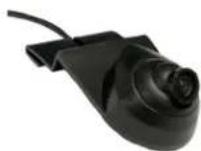
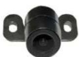
Optional aftermarket add on cameras are available for the VRFCH-75Y. Cameras available and sold separately include: (More cameras can be found at www.cruxinterfacing.com)
CDR-31C Cargo Camera for RAM Trucks
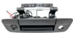
CDR-02 Tailgate Handle
Camera for RAM Trucks

natural_image
Product photo of a mechanical device with a black circular component, coiled cable, and small accessories (no visible text or symbols)Jeep Wrangle Spare Tire Mount Camera

CUB-15 Adjustable Angle Camera
CFF-01 Bullet Type Front Camera
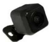
CFF-02 Square Body Front
Camera
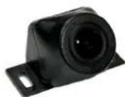
CFF-03 Grille Mount Front
Camera
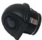
CUL-16 Universal Lip Mount Camera

INSTALLATION DIAGRAM:

flowchart
graph TD
    A["TO RADIO"] --> B["Gray 22-PIN (MALE)"]
    A --> C["WHITE 22-PIN (MALE)"]
    A --> D["GRAY 22-PIN (FEMALE)"]
    A --> E["WHITE 22-PIN (FEMALE)"]
    B --> F["BRIDGE"]
    C --> F
    D --> F
    E --> F
    F --> G["CRUX Device"]
    G --> H["Connect this 6-pin plug if OEM backup camera is being used"]
    H --> I["Audio/Video Input"]
    H --> J["Audio/Video Output"]
    H --> K["Front and Rear Camera Power Output 12V (purple/white)"]
    H --> L["Video Input Power Output 12V (orange/white)"]
    H --> M["Front Camera Input"]
    H --> N["Aftermarket Backup Camera Input"]
    H --> O["Video Input"]
DIP SWITCH SETTINGS:
| DIP# | ON | OFF |
| 1 | No Function – Leave OFF | |
| 2 | Front Camera ON | Front Camera OFF |
| 3 | Set to OFF | |
| 4 | Set to OFF | |
| 5 | Video Input ON | Video Input OFF |
| 6 | Set to OFF | |
| 7 | AUX A/V ON | AUX A/V OFF |
| 8 | Set to OFF | |
OPERATION:
Installation example is on a 2016 Jeep Wrangler. Other vehicle installation will vary.

natural_image
Close-up of a hand pressing down on a black car intake tray (no visible text or symbols)- Remove the rubber lining on the compartment on the dashboard. Remove one screw.

natural_image
Interior view of a car showing a hand interacting with the dashboard of the Keitabat, with a digital map on the steering wheel (no visible text or symbols)- Carefully pry out the power window switch assembly.
natural_image
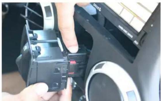
Close-up of hands installing a black plastic component on a mechanical device (no visible text or symbols)- Unplug the power window switch connector. 4. Remove the screw behind the power window switch housing.

natural_image
Close-up of hands adjusting a camera mode dial and adjustment knob on a car dashboard (no visible text or symbols)
natural_image
Close-up of hands installing or adjusting a car interior panel, showing a mesh grille and battery compartment (no text or symbols visible)- Remove the lower panel under the steering wheel column.

natural_image
Close-up of a hand holding a screwdriver inserted into a car dashboard (no visible text or symbols)- Remove the screw holding the upper dash trim panel.

natural_image
Interior view of a car showing hands operating the dashboard and steering wheel (no visible text or symbols)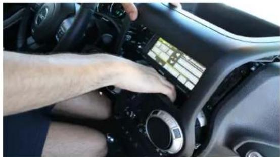
natural_image
Interior view of a car dashboard with a hand adjusting the dashboard (no visible text or symbols)- Raise the upper dash panel to release the radio bezel. 8. Carefully pull out the radio bezel and set aside.


natural_image
Close-up of hands installing or adjusting a component on a car chassis (no visible text or symbols)- Remove the 4 screws holding the radio. 10. Pull out the radio and unplug the OEM connectors.

natural_image
Close-up of hands installing or adjusting a component into a car's front panel, showing wiring and components (no visible text or symbols)
natural_image
Close-up of a car interior showing a hand holding wires connected to a camera (no visible text or symbols)-
Plug in the VRFCH-75Y T-harness between the radio and vehicle harness.
-
Mount the cameras being used and tuck the module and the harness behind the radio. Reverse the process to reinstall the radio and trim panels.
-
Plug the camera cables and connect the corresponding camera power output wires.

natural_image
Close-up of hands interacting with a car infotainment device, showing cable routing and a control panel (no visible text or symbols)
natural_image
Close-up of a hand adjusting a camera mode dial (no visible text or symbols)- To force view and toggle between the cameras, press and hold the middle button on the right side steering wheel control. Each press will toggle to the camera that is set to ON on the DIP switches. See page 2 for DIP switch settings.

- The front camera (if installed) will automatically show on the screen for 10 seconds when the gear is put to Drive from Reverse.
To enter AV mode, press and hold the left side steering wheel control center button for 5 seconds then press "View Video" on the screen.

FORCED VIEW CAMERA SEQUENCE:
Using OEM backup Camera
FRONT → VIDEO INPUT → AV INPUT
Using Aftermarket backup Camera
FRONT → BACKUP → VIDEO INPUT → AV INPUT
VEHICLE APPLICATIONS:
CHRYSLER DODGE
2011-2014 200
2008-2010 300/300C
2008-2010 Aspen
2007 – 2011 Sebring
2008 – 2017 Town & Country
2007 – 2015 Avenger
2010 – 2012 Caliber
2008 – 2017 Caravan
2009 – 2014 Challenger
2008 – 2010 Charger
2008 – 2012 Dakota
2008 – 2013 Durango
2009 – 2010 Journey
2007 – 2012 Nitro
JEEP
2008 - 2010 Commander
2008 – 2016 Compass
2008 – 2013 Grand Cherokee
2008 – 2015 Liberty
2009 – 2017 Patriot
2007-2018 Wrangler
RAM
2009 – 2012 Ram

5 of 5
rev.022019
Brand : CRUX
Model : VRFCH-75Y
Category : Air conditioner