
KASMM39S24A - Wall air conditioner Kogan - Free user manual and instructions
Find the device manual for free KASMM39S24A Kogan in PDF.


| Product Type | Wall Air Conditioner (Split System) |
| Brand | Kogan |
| Model | KASMM39S24A |
| Cooling Capacity | 39000 BTU/h |
| Heating Capacity | 40000 BTU/h (Heat Pump) |
| Energy Efficiency Ratio (EER) | 10.5 |
| Seasonal Energy Efficiency Ratio (SEER) | 13.0 |
| Power Supply | 220-240V / 50Hz |
| Refrigerant | R410A |
| Indoor Unit Dimensions (W x H x D) | 1100 x 350 x 250 mm |
| Outdoor Unit Dimensions (W x H x D) | 950 x 700 x 350 mm |
| Indoor Unit Weight | 15 kg |
| Outdoor Unit Weight | 45 kg |
| Air Flow Rate | 1200 m³/h |
| Noise Level (Indoor) | 45 dB(A) |
| Noise Level (Outdoor) | 55 dB(A) |
| Functions | Cooling, Heating, Fan, Dehumidifier, Timer, Sleep Mode |
| Remote Control | Included with LCD display |
| Air Filter | Washable, reusable |
| Installation | Professional installation required |
| Cleaning | Clean filter every 2 weeks; wipe unit with soft dry cloth |
| Safety Features | Overheat protection, auto restart, child lock |
| Spare Parts Availability | Contact Kogan support for genuine parts |
| Repairability Score | 6.0 / 10 |
Frequently Asked Questions - KASMM39S24A Kogan
User questions about KASMM39S24A Kogan
0 question about this device. Answer the ones you know or ask your own.
Ask a new question about this device
Download the instructions for your Wall air conditioner in PDF format for free! Find your manual KASMM39S24A - Kogan and take your electronic device back in hand. On this page are published all the documents necessary for the use of your device. KASMM39S24A by Kogan.
USER MANUAL KASMM39S24A Kogan
natural_image
Technical line drawing of a robotic arm with two articulated arms and a central base (no text or symbols)FULL MOTION SPRING-ASSISTED RGB GAMING MONITOR MOUNT
WITH USB HUB (DUAL)
KASMM39S24A
SAFETY & WARNINGS
Read the entire user guide before you start Installation and assembly. If you have any question regarding any of the instruction or warnings, please contact Kogan.com for assistance.
CAUTION: Usage with products heavier than the rated weights indicated may result in instability causing possible injury.
- Please closely follow the assembly instructions. Improper installation may result in damage or serious personal injury.
- Safety gear and proper tools must be used. This product should only be installed by professionals.
- This product is designed to be installed on solid concrete walls, masonry walls or wood stud walls.
- Make sure that the supporting surface will safely support the combined weight of the equipment and all attached hardware and components.
- Use the mounting screws provided and DO NOT OVER TIGHTEN mounting screws.
- This product contains small items that could be a choking hazard If swallowed. Keep these items away from children.
- This product is intended for indoor use only. Using this product outdoors could lead to product failure and personal injury.
IMPORTANT: Ensure that you have received all parts according to the component checklist prior to Installation. If any parts are missing or faulty, contact Kogan.com tor a replacement.
MAINTENANCE: Check that the product is secure and safe to use at regular intervals (at least every three months).
COMPONENTS

natural_image
Line drawing of a robotic arm with two articulated joints (no text or symbols)A (x1)

B (x2)

F(x1)

J
M6x12 (x3)
C (x1)

G (x1)

K
M6x10 (x2)

D (x1)
H (x1)
L (x2)

E (x1)
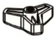
I (x1)

M
4mm (x1)

N
6mm (x1)

O (x1)
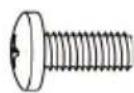
M-A M4x12 (x8)

M-B M5x12 (x8)
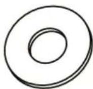
M-C D5 (x8)
OVERVIEW
Inputs and controls

Connect to the computer
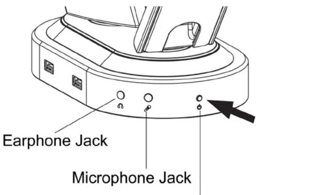
Light switch button (To turn ON/OFF, press for 2 seconds)
INSTALLING TO DESK
A CONFIGURATION (CLAMP)
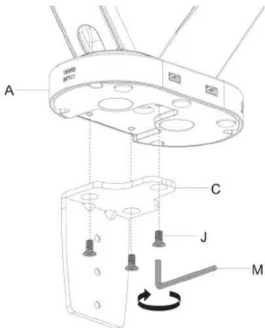
Step 1: Connect C to the base of the mount (A) with J screws (M6x12mm), using the Allan key (M) to secure.
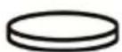
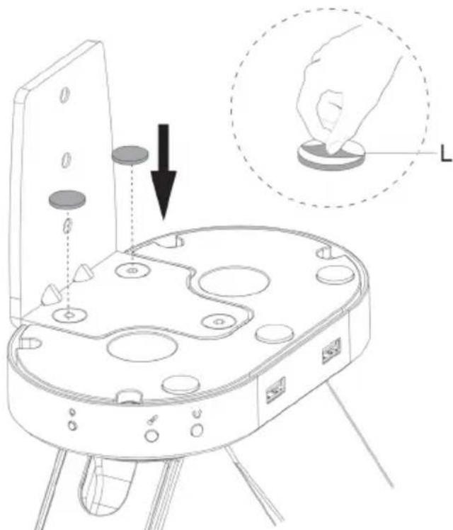
Step 2: Place L pads on the base of the mount. This protects your desk from scuffing from the J screws.
natural_image
Technical line drawing of a mechanical device with a hand pressing a circular component labeled 'L' (no text or symbols on the device itself)Step 3: Select the positioning of D based on the thickness of the desk you're installing the mount onto. For 10-55mm thickness, use position A. For 50-85mm, use position B.

Position A

Position B
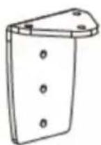
Step 4: Fit the cable management/cover piece (G) onto the back of the mount assembly. Place onto your desk and turn knob to tighten.


natural_image
Technical line drawing of a mechanical assembly with a rotating base and mounting bracket (no text or symbols)Notes:
- Some desks come prepared with a hole for thread-hole mounting. If your desk does not, a 10mm hole will have to be manually drilled for this configuration.
- If you do not wish to drill a permanent hole in your desk, refer to 'A Configuration', which uses the clamp method.
Step 1: With the F bolt in position, connect E to the base of the mount (A) with J screws (M6x12mm), using the Allan key (M) to secure.

Step 2: Place L pads on the base of the mount. This protects your desk from scuffing from the J screws.

natural_image
Technical line drawing of a mechanical device with threaded shaft and mounting holes, showing assembly and component alignment (no text or symbols)Step 3: Place mount onto desk, threading the bolt (F) through the hole. Ensure the hole is φ 10mm (or φ 3 / 8 ). Fit H bracket and I knob, then tighten knob to secure.

MOUNTING MONITORS
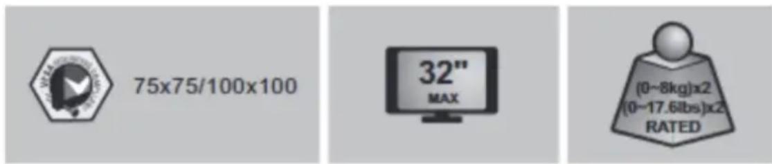
Step 1: To fit the VESA mount to your monitors, use the provided screws (M-A. M-B) and washers (M-C) to ensure the correct length – it is important not to insert a screw that is too long, as it may permanently damage your monitor. Refer to monitor's specifications to be sure. Use a Phillip's head screw driver (not supplied) to tighten (do NOT use a drill) and do not force past point of resistance.

Step 2: Turn the locking mechanism to ‘unlock’ position, then with two people lift the monitor up and attach to the stand. Then turn the locking mechanism back to ‘lock’ position to secure.

natural_image
Two stylized human figures holding a rectangular object, no text or symbols present
Step 3: Use the M and N Allen Keys to tighten the mount into your preferred position.

Step 4: Using a Phillips head screw driver (not supplied), remove the cable management covers. Once your cables are in place, replace the cover.
Removing:

natural_image
Technical line drawing of a mechanical assembly with labeled components and an inset showing a screwdriver (no text or symbols present)Replacing:

Step 5: Rotate the monitors if needed. If the display does not stop at your desired position, tighten the screws (a) and (b) as shown.

NOTES
Need more information?
We hope that this user guide has given you
the assistance needed for a simple set-up.
For the most up-to-date guide for your product, as well as any additional assistance you may require, head online to help.kogan.com
kogan.com

Brand : Kogan
Model : KASMM39S24A
Category : Wall air conditioner