
BKM-68X - Computer Adapter SONY - Free user manual and instructions
Find the device manual for free BKM-68X SONY in PDF.


| Type de produit | Analog Component Input Adaptor for Sony BVM-A series monitors |
| Marque | Sony |
| Modèle | BKM-68X |
| Dimensions (L x H x P) | 25 × 256 × 248 mm |
| Poids | Environ 900 g |
| Alimentation | +5 V, ±6 V (fourni par le moniteur) |
| Consommation électrique | 7,5 W max |
| Connecteurs d'entrée analogique | 3 × BNC (Y/PB/PR ou GBR), haute impédance, avec sortie en boucle |
| Connecteurs SYNC externe | 1 × BNC, haute impédance, avec sortie en boucle |
| Niveau du signal Y | 1 Vp-p ±6 dB |
| Niveau du signal PB/PR | 0,7 Vp-p ±6 dB |
| Niveau du signal G/B/R | 1 Vp-p ±6 dB (sync sur G) |
| Caractéristiques en fréquence (Y, PB/PR, G/B/R) | 48 Hz à 30 MHz ±3 dB |
| Compensation d'ouverture | 480/59.94I, 575/50I: 6 dB min (5 MHz); autres: 6 dB min (25 MHz) |
| Perte de retour | -40 dB max (7 MHz) |
| Niveau du signal SYNC externe | 0,3 à 4 Vp-p |
| Conditions de fonctionnement (température) | 0 °C à 35 °C |
| Conditions de fonctionnement (humidité) | 0 % à 90 % (sans condensation) |
| Fonctions principales | Entrée et sortie pour signaux analogiques composants Y/PB/PR ou GBR; entrée SYNC externe avec boucle; installation dans un slot option du moniteur |
| Entretien et nettoyage | Aucun entretien spécifique requis; nettoyer avec un chiffon sec |
| Sécurité | Suivre les instructions FCC Classe A; utiliser des câbles blindés |
| Accessoires fournis | Mode d'emploi (1) |
Frequently Asked Questions - BKM-68X SONY
User questions about BKM-68X SONY
0 question about this device. Answer the ones you know or ask your own.
Ask a new question about this device
Download the instructions for your Computer Adapter in PDF format for free! Find your manual BKM-68X - SONY and take your electronic device back in hand. On this page are published all the documents necessary for the use of your device. BKM-68X by SONY.
USER MANUAL BKM-68X SONY
1st Edition (Revised 2)
Serial No. 2000001 and Higher
安全のために

下記の注意を守らないと、
けがをしたり周辺の物品に損害を
与えることがあります。

フラグをコン セントから抜く
G/B/R:48 Hz \~ 30 MHz ± 1 dB
色信号/輝度信号
遲延時間誤差
10 nsec 以内
利得誤差 3% 以内
アパーチャー補正
6 dB 以上 (25 MHz)
量子化 10ビット/サンプル
G/B/R:48 Hz \~ 30 MHz ± 3 dB
アパーチャー補正
480/59.94I, 575/50I:6 dB 以上 (5 MHz)
natural_image
Front view of a server rack unit with multiple ports and connectors (no visible text or labels)4 上下のネジを締めて固定する。

natural_image
Technical line drawing of a server rack unit with multiple ports and ventilation grilles (no text or symbols)ご注意
For customers in the USA
This equipment has been tested and found to comply with the limits for a Class A digital device, pursuant to Part 15 of the FCC Rules. These limits are designed to provide reasonable protection against harmful interference when the equipment is operated in a commercial environment. This equipment generates, uses, and can radiate radio frequency energy and, if not installed and used in accordance with the instruction manual, may cause harmful interference to radio communications. Operation of this equipment in a residential area is likely to cause harmful interference in which case the user will be required to correct the interference at his own expense.
You are cautioned that any changes or modifications not expressly approved in this manual could void your authority to operate this equipment.
The shielded interface cable recommended in this manual must be used with this equipment in order to comply with the limits for a digital device pursuant to Subpart B of Part 15 of FCC Rules.
This device complies with part 15 of the FCC Rules. Operation is subject to the following two conditions:
(1) this device may not cause harmful interference, and (2) this device must accept any interference received, including interference that may cause undesired operation.
For customers in Canada
This Class A digital apparatus complies with Canadian ICES-003.
For the customers in Europe
This product with the CE marking complies with the EMC Directive (89/336/EEC) issued by the Commission of the European Community.
Compliance with this directive implies conformity to the following European standards:
• EN55103-1: Electromagnetic Interference (Emission)
- EN55103-2: Electromagnetic Susceptibility (Immunity) This product is intended for use in the following Electromagnetic Environment: E4 (controlled EMC environment, ex. TV studio).
Table of Contents 15
BKM-61D SDI/Analog Multi Input Adaptor.... 16
Functions 16
Using the input and output connectors 16
Specifications 17
BKM-62HS HD SDI/SDI Input Adaptor....18
Functions 18
Using the input and output connectors ....18
Specifications 19
BKM-68X Analog Component Input Adaptor 20
Functions 20
Using the input and output connectors 20
Specifications 21
List of Input and Output Connectors....22
Installing into Video Monitors 23
Available Signal Formats 24
BKM-61D SDI/Analog Multi Input Adaptor
The BKM-61D SDI/Analog Multi Input Adaptor is a video signal input adaptor for Sony BVM-A series color video monitors. When installed in an input option slot on the rear panel of the video monitor, it provides input and output connectors for 4:2:2 component digital, composite digital, analog composite and Y/C signals for the monitor.
Functions
Decoder for serial digital signals/analog composite signals
The BKM-61D is equipped with a decoder for component digital (525/625), composite digital (NTSC/PAL), analog composite (NTSC/PAL/PAL-M/SECAM) and Y/C signals.
Input and output connectors for serial digital signals/analog composite signals
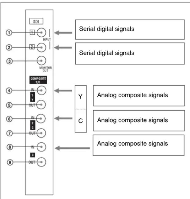
The BKM-61D is equipped with two input and one monitor output connectors for serial digital signals, as well as three input and three output connectors for analog signals. You can input and output Y/C signals using the upper four of the six connectors for analog signals.
Using the input and output connectors
Configuration of input/output connectors and signals that may be input
The configuration of the input and output connectors and the signals that may be input are shown below.
flowchart
graph TD
    A["①"] --> B["SDI"]
    B --> C["INPUT"]
    C --> D["②"]
    D --> E["③"]
    E --> F["MONITOR OUT"]
    F --> G["COMPOSITE Y/C"]
    G --> H["Y"]
    G --> I["C"]
    H --> J["Serial digital signals"]
    I --> K["Analog composite signals"]
    J --> L["Serial digital signals"]
    K --> M["Analog composite signals"]
    L --> N["Serial digital signals"]
    M --> O["Analog composite signals"]
    N --> P["Serial digital signals"]
    O --> Q["Analog composite signals"]
Input of serial digital signals
You can input serial digital signals to the connectors ① and ②. You can select either of the signals to output from the connector ③ (Monitor output). You do not have to attach a 75-ohm terminator to the connector ③.
Notes
- Only the format of signals that you specified using the INPUT CONFIGURATION menu (or the format of the signals that is last received when AUTO is selected) will be properly output from the MONITOR OUT connector.
- The signals can be output from the MONITOR OUT connector only when the power of the monitor is ON. No signal will be output from the connector when the monitor is in the standby status.
- The MONITOR OUT signals do not satisfy the ONLINE signal specifications.
For details on INPUT CONFIGURATION menu, see “☐ Setting the Input Configuration – INPUT CONFIGURATION Menu” in the Operation Manual for your monitor.
Input of analog composite signals
You can input analog composite signals to the connectors ④, ⑥, and ⑧. You can obtain loop-through output of these signals from the connectors ⑤, ⑦, and ⑨ respectively. If you do not use loop-through output, attach 75-ohm terminators to the connectors ⑤, ⑦, and ⑨.
Input of Y/C signals
You can input Y signals to the connector ④, and C signals to the connector ⑥. You can obtain loop-through output of these signals from the connectors ⑤ and ⑦ respectively. If you do not use loop-through output, attach 75-ohm terminators to the connectors ⑤ and ⑦.
For details on installation of the BKM-61D in a video monitor, see “Installing into Video Monitors” (page 23).
Assigning input signals to connectors
After installing the BKM-61D in the video monitor, make necessary settings for each input channel using the INPUT CONFIGURATION menu of the monitor. The BKM-61D may not work properly without the settings.
For details on INPUT CONFIGURATION menu, see “☐ Setting the Input Configuration – INPUT CONFIGURATION Menu” in the Operation Manual for your monitor.
Specifications
General
Voltage +5 V, ±6 V (supplied from the monitor)
Power consumption
6 W max.
Operating conditions
Temperature 0°C to 35°C (32°F to 95°F)
Optimum temperature
20^ to 30^ (68°F to 86°F)
Humidity 0% to 90% (no condensation)
Pressure 700 hPa to 1060 hPa
Storage and transport conditions
Temperature -10^ to 40^ (14°F to 104°F)
Humidity 0% to 90%
Pressure 700 hPa to 1060 hPa
Maximum external dimensions (w/h/d)
25 × 256 × 248 mm
(1× 10^1 / 8× 9^7 / 8 inches)
Mass approx. 930 g (2 lb 1 oz)
Input/output connectors
Digital input BNC × 2, with monitor output × 1
Analog input BNC × 3, high impedance, with loop-
through output
Signal characteristics
Analog composite and Y/C signals
Signal level
Analog composite
1 Vp-p +2 dB/-6 dB
Y/C Y: 1 Vp-p +2 dB/-6 dB
C (NTSC): 0.286 Vp-p +2 dB/-6 dB
(burst signal level)
C (PAL): 0.3 Vp-p +2 dB/-6 dB (burst
signal level)
Luminance signal
Frequency characteristics
Analog composite
Filter off: 50 Hz to 5 MHz ±2 dB
Filter on: -30 dB relative to sub carrier
frequency
Y/C Y: 50 Hz to 5.75 MHz ±2 dB
Chrominance signal
Demodulation axis
R-Y/B-Y
Chrominance signal band
R-Y: 1.3 MHz -3 dB
B-Y: 1.3 MHz -3 dB
Chroma phase adjustment range
NTSC: ±15^ min.
DG (differential gain)
APL 10% to 90%
2% max. (Y: amplitude 1 Vp-p)
DP (differential phase)
APL 10% to 90%
2^ max. (Y: amplitude 1 Vp-p)
Chrominance signal/luminance signal
Delay time error
35 nsec max.
Gain error 5% max.
Aperture compensation
6 dB min. (5 MHz)
Return loss -40 dB max. (7 MHz)
Digital component (525, 625) and digital composite (NTSC, PAL) signals
Component
Sampling frequency
Y: 13.5 MHz
R-Y/B-Y: 6.75 MHz
Frequency characteristics
Y: 50 Hz to 5.75 MHz ±1 dB
R-Y/B-Y: 50 Hz to 2.75 MHz ±1 dB
Chrominance signal/luminance signal
Delay time error: 30 nsec max.
Gain error: 5% max.
Aperture compensation
6 dB min. (5 MHz)
Composite
Sampling frequency
NTSC: 14.3 MHz
PAL: 17.7 MHz
Frequency characteristics
Y: 50 Hz to 5 MHz ±2 dB
R-Y/B-Y: 1.3 MHz -3 dB
Chrominance signal/luminance signal
Delay time error: 35 nsec max.
Gain error: 5% max.
Aperture compensation
6 dB min. (5 MHz)
Quantization 10 bits/sample
Transmission distance
200 m (approx. 656 ft) max. (When
using 5C-2V coaxial cables (Fujikura,
Return loss -15 dB max. (5 to 270 MHz)
Accessories supplied
Operation Manual (1)
Design and specifications are subject to change without notice.
BKM-62HS HD SDI/SDI Input Adaptor
The BKM-62HS HD SDI/SDI Input Adaptor is a video signal input adaptor for Sony BVM-A series color video monitors. When installed in an input option slot on the rear panel of the video monitor, it provides input and output connectors for 4:4:4 HD serial digital (dual link), 4:2:2 HD serial digital, and 4:2:2 serial digital component signals for the monitor.
Functions
Decoder for HD serial digital signals (dual link/single link)/SD serial digital signals
The BKM-62HS automatically detects the type of signals you input and decodes HD serial digital signals and SD serial digital signals (component). You can also input dual link HD-SDI 4:4:4 RGB/YP _B PR signals (1080/24PsF or 1080/60I, for example) to the adaptor.
Input and output connectors for HD serial digital signals/SD serial digital signals
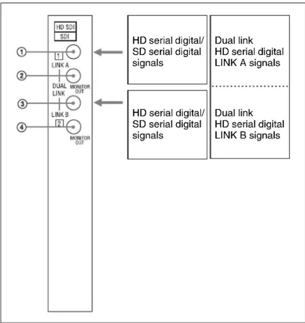
The BKM-62HS is equipped with two input and two monitor output connectors for HD serial digital signals and SD serial digital signals.
Note
When 1080/24PsF, 25PsF, or 30PsF signal is input, the monitor displays it in an interlace (1080/48I, 50I, or 60I) signal format.
Using the input and output connectors
Configuration of input/output connectors and signals that may be input
The configuration of the input and output connectors and the signals that may be input are shown below.
flowchart
graph TD
    A["HD SDI SDI"] --> B["1"]
    A --> C["2"]
    A --> D["3"]
    A --> E["4"]
    B --> F["LINK A"]
    C --> G["DUAL LINK MONITOR OUT"]
    D --> H["LINK B"]
    E --> I["2"]
    J["HD serial digital/SD serial digital signals"] --> K["1"]
    L["HD serial digital/SD serial digital signals"] --> M["2"]
    N["Dual link HD serial digital LINK A signals"] --> O["1"]
    P["Dual link HD serial digital LINK B signals"] --> Q["2"]
Input of HD serial digital signals/SD serial digital signals
You can input serial digital signals to the connectors ① and ③. You can output these signals from the connectors ② and ④ respectively (Monitor output). You do not have to attach 75-ohm terminators to the connectors ② and ④.
Input of dual link HD serial digital signals
You can input LINK A signals to the connector ①, and LINK B signals to the connector ③. You can output these signals from the connectors ② and ④ respectively (Monitor output). You do not have to attach 75-ohm terminators to the connectors ② and ④.
Notes
- The signals can be output from the MONITOR OUT connectors only when the power of the monitor is ON. No signal will be output from the connectors when the monitor is in the standby status.
- The MONITOR OUT signals do not satisfy the ONLINE signal specifications.
For details on installation of the BKM-62HS in a video monitor, see “Installing into Video Monitors” (page 23).
Assigning input signals to connectors
After installing the BKM-62HS in the video monitor, make necessary settings for each input channel using the INPUT CONFIGURATION menu of the monitor. The BKM-62HS may not work properly without the settings.
For details on INPUT CONFIGURATION menu, see “☑ Setting the Input Configuration – INPUT CONFIGURATION Menu” in the Operation Manual for your monitor.
Specifications
General
Voltage +5 V, ±6 V (supplied from the monitor)
Power consumption
5.5 W max.
Operating conditions
Temperature 0°C to 35°C (32°F to 95°F)
Optimum temperature
20^ to 30^ (68°F to 86°F)
Humidity 0% to 90% (no condensation)
Pressure 700 hPa to 1060 hPa
Storage and transport conditions
Temperature -10^ to 40^ (14°F to 104°F)
Humidity 0% to 90%
Pressure 700 hPa to 1060 hPa
Maximum external dimensions (w/h/d)
25 × 256 × 248 mm
(1× 10^1 / 8× 9^ / 8 inches)
Mass approx. 910 g (2 lb)
Input/output connectors
Digital input BNC × 2 (75 ohm), with monitor output
Signal characteristics
HD digital component signals
HD SDI reception characteristic:
Input impedance
75 ohm unbalanced
Data rate 1.4835 Gbps to 1.485 Gbps
Monitor output:
Output signal amplitude
800 mVp-p ±10%
Output impedance
75 ohm unbalanced
Frequency characteristics
Y: 48 Hz to 30 MHz ±1 dB
P_B / P_R : 48Hz to 30MHz± 1 dB
G/B/R: 48 Hz to 30 MHz ±1 dB
Chrominance signal/luminance signal
Delay time error
10 nsec max.
Gain error 3% max.
Aperture compensation
6 dB min. (25 MHz)
Quantization 10 bits/sample
Transmission distance
100 m (approx. 328 ft) max. (When
using 5C-FB coaxial cables (Fujikura, Inc.) or equivalent.)
Return loss -15 dB max. (5 MHz to 1.485 GHz)
SD digital component signals
Sampling frequency
Y: 13.5 MHz
R-Y/B-Y: 6.75 MHz
Frequency characteristics
Y: 50 Hz to 5.75 MHz ±1 dB
R-Y/B-Y: 50 Hz to 2.75 MHz ±1 dB
Chrominance signal/luminance signal
Delay time error
30 nsec max.
Gain error 5% max.
Aperture compensation
6 dB min. (5 MHz)
Quantization
10
bits/sample
Transmission distance
200 m (approx. 656 ft) max. (When
using 5C-2V coaxial cables (Fujikura,
Accessories supplied
Operation Manual (1)
Design and specifications are subject to change without notice.
BKM-68X Analog Component Input Adaptor
The BKM-68X Analog Component Input Adaptor is a video signal input adaptor for Sony BVM-A series color video monitors. When installed in an input option slot on the rear panel of the video monitor, it provides input and output connectors for analog component/RGB signals for the monitor.
Functions
Input and output connectors for analog component signals/analog RGB signals
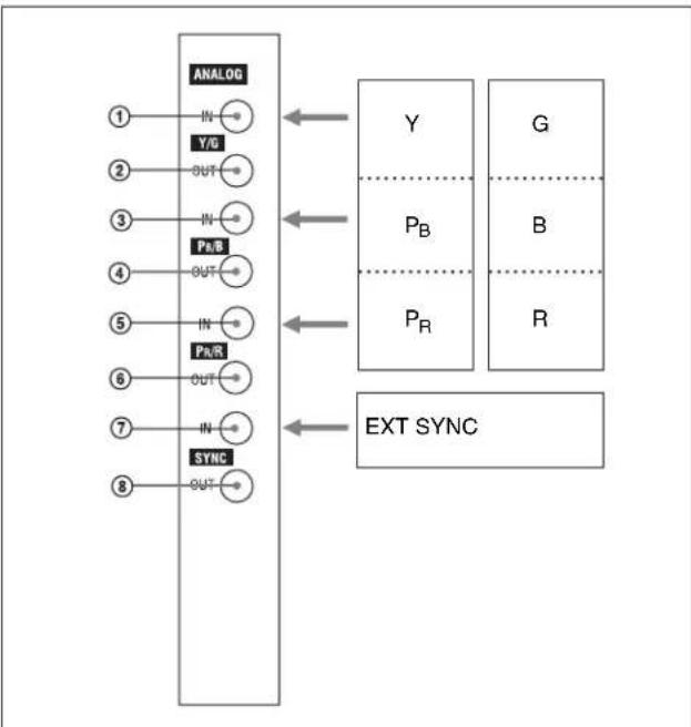
The BKM-68X is equipped with a set of input and output connectors for analog component and RGB (Y/P _B /P _R , GBR) signals.
Input and output connectors for EXT SYNC (external synchronizing) signals
The BKM-68X is equipped with a set of input and output connectors for EXT SYNC (external synchronizing) signals.
Note
The external synchronizing signals input to the connector work only for analog component/RGB signals input to the BKM-68X.
Using the input and output connectors
Configuration of input/output connectors and signals that may be input
The configuration of the input and output connectors and the signals that may be input are shown below.
flowchart
graph TD
    A["ANALOG"] --> B["IN"]
    A --> C["Y/G"]
    A --> D["OUT"]
    A --> E["IN"]
    A --> F["PN/B"]
    A --> G["OUT"]
    A --> H["IN"]
    A --> I["PN/R"]
    A --> J["OUT"]
    A --> K["IN"]
    A --> L["SYNC"]
    L --> M["OUT"]
    N["Y"] --> O["EXT SYNC"]
    P["P_B"] --> Q["EXT SYNC"]
    R["P_R"] --> S["EXT SYNC"]
    T["G"] --> U["EXT SYNC"]
    V["B"] --> W["EXT SYNC"]
    X["R"] --> Y["EXT SYNC"]
Input of analog component signals/analog RGB signals
You can input Y or G signals to the connector ①, P_B or B to the connector ③, P_R or R to the connector ⑤, and external composite synchronizing signals to the connector ⑦. You can obtain loop-through output of these signals from the connectors ②, ④, ⑥, and ⑧ respectively. If you do not use loop-through output, attach 75-ohm terminators to the connectors ②, ④, ⑥, and ⑧.
For details on installation of the BKM-68X in a video monitor, see "Installing into Video Monitors" (page 23).
Assigning input signals to connectors
After installing the BKM-68X in the video monitor, make necessary settings for each input channel using the INPUT CONFIGURATION menu of the monitor. The BKM-68X may not work properly without the settings.
For details on INPUT CONFIGURATION menu, see "C Setting the Input Configuration – INPUT CONFIGURATION Menu" in the Operation Manual for your monitor.
Specifications
General
Voltage +5 V, ±6 V (supplied from the monitor)
Power consumption
7.5 W max.
Operating conditions
Temperature 0°C to 35°C (32°F to 95°F)
Optimum temperature
20^ to 30^ (68°F to 86°F)
Humidity 0% to 90% (no condensation)
Pressure 700 hPa to 1060 hPa
Storage and transport conditions
Temperature -10^ to 40^ (14°F to 104°F)
Humidity 0% to 90%
Pressure 700 hPa to 1060 hPa
Maximum external dimensions (w/h/d)
25 × 256 × 248 mm
(1× 10^1 / 8× 9^7 / 8 inches)
Mass approx. 900 g (1 lb 16 oz)
Input/output connectors
Analog input (Y/P B /P R , GBR)
BNC × 3, high impedance, with loop-
through output
EXT SYNC (external synchronizing) input
BNC × 1, high impedance, with loop-
through output
3-level synchronization (positive or
negative), 2-level synchronization
(negative)
Signal characteristics
Analog component (Y/P _B /P _R , GBR) signals
Signal level Y: 1 Vp-p ±6 dB
P_B / P_R : 0.7 Vp-p ±6 dB
G/B/R: 1 Vp-p ±6 dB (sync on G)
Frequency characteristics
Y: 48 Hz to 30 MHz ±3 dB
P_B / P_R : 48 Hz to 30 MHz ±3 dB
G/B/R: 48 Hz to 30 MHz ±3 dB
Aperture compensation
480/59.94I, 575/50I: 6 dB min.
(5 MHz)
Other than the above: 6 dB min.
(25 MHz)
Return loss -40 dB max. (7 MHz)
EXT SYNC (external synchronizing) signals
Signal level EXT SYNC: 0.3 to 4 Vp-p
Return loss -40 dB max. (7 MHz)
Accessories supplied
Operation Manual (1)
Design and specifications are subject to change without notice.
List of Input and Output Connectors
The table shows the configuration of the input and output connectors and the signals that may be input to the BKM-61D, the BKM-62HS, and the BKM-68X.
You must specify the type and format of signals input to each connector using the INPUT CONFIGURATION menu of your monitor.
| Signal format\Adaptors | BKM-61D SDI/Analog Multi Input Adaptor | BKM-62HS HD SDI/SDI Input Adaptor | BKM-68X Analog Component Input Adaptor | |
| Serial digital inputs | Component 525/625 | ○ | ○ | |
| Composite NTSC | ○ | |||
| Composite PAL | ○ | |||
| HD-SDI ○ | ||||
| Analog inputs | Composite NTSC ○ | |||
| Composite PAL ○ | ||||
| Composite PAL-M ○ | ||||
| Composite SECAM ○ | ||||
| YP _B PR 525/625 ○ | ||||
| GBR 525/625 ○ | ||||
| Y/C NTSC ○ | ||||
| Y/C PAL ○ | ||||
| Y/C PAL-M ○ | ||||
| Y/C SECAM ○ | ||||
| YP _B PR/GBR 1080/48I | ○ | |||
| YP _B PR/GBR 1080/50I | ○ | |||
| YP _B PR/GBR 576/50P | ○ | |||
| YP _B PR/GBR 480/60P | ○ | |||
| YP _B PR/GBR 1035/60I | ○ | |||
| YP _B PR/GBR 1080/60I | ○ | |||
| YP _B PR/GBR 720/50P | ○ | |||
| YP _B PR/GBR 720/60P | ○ | |||
| Number of digital inputs 2 | 2 | - | ||
| Number of analog inputs | 3 | - | 1 | |
O: Input possible
Installing into Video Monitors
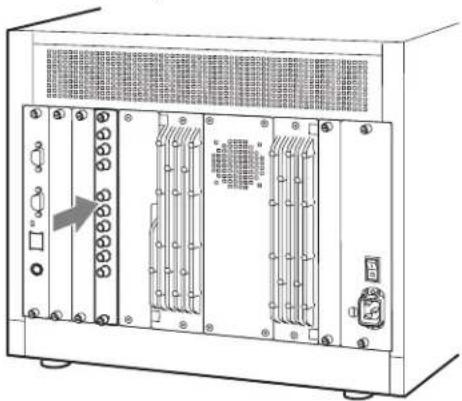
Each adaptor can be installed in any input option slot of the monitor.
Be sure to turn your video monitor's MAIN POWER switch off and unplug the AC power cord from your monitor before installing or removing adaptors.
1 Remove the cover of an input option slot on the rear panel of your video monitor.

Check that the video monitor's MAIN POWER switch is off, and then unplug the AC power cord.
2 Insert the adaptor below the alignment mark on the left of the upper screw hole of the slot.

3 Push the adaptor in until it is firmly seated in the connector inside your video monitor.
natural_image
Front view of a server rack unit with multiple ports and ventilation grilles (no visible text or labels)4 Tighten the both screws to retain the adaptor.

natural_image
Technical line drawing of a server rack unit with multiple ports and ventilation grilles (no text or symbols)Notes
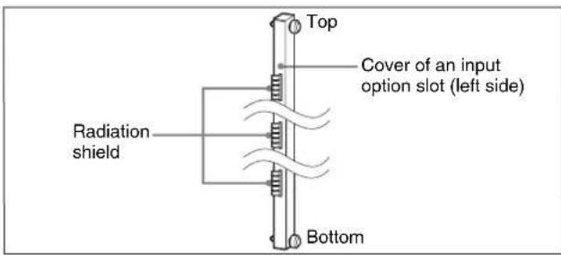
- The covers of input option slots have radiation shields on their left side. Handle the covers with care to avoid damaging them.
- When you remove the installed adaptors and reattach the covers to the input option slots, be sure to attach them with the radiation shields facing left.
- If you attach the covers upside down, or attach the covers with damaged radiation shields, your monitor may not conform to the radiation standards.
Available Signal Formats
| Signal format | System BKM-61D BKM-62HS BKM-68X Standard | ||||||
| Analog Composite | |||||||
| NTSC | Setup level | 0 | 480/59.94I O | × | × | SMPTE 170M | |
| 7.5 | |||||||
| PAL 575/50I O | × | × | Rec.ITU-R BT.470 | ||||
| PAL-M 480/59.94I O | × | × | Rec.ITU-R BT.470 | ||||
| SECAM 575/50I O | × | × | Rec.ITU-R BT.470 | ||||
| Analog (Y/C) | |||||||
| NTSC | Setup level | 0 | 480/59.94I O | × | × | ||
| 7.5 | |||||||
| PAL 575/50I O | × | × | |||||
| PAL-M 480/59.94I O× | × | ||||||
| SECAM 575/50I O× × | |||||||
| Analog Component | |||||||
| 1035/60I* | × | × | OSMPTE 240M/BTA S-001B | ||||
| 1080/60I* | × | × | ○ | SMPTE 274M | |||
| 1080/50I | × | × | ○ | ||||
| 1080/30PsF* | × | × | ○ | SMPTE RP 2111080/25PsF | |||
| × | × | ○ | |||||
| 1080/24PsF* | × | × | ○ | ||||
| 720/60P* | × | × | ○ | SMPTE 296M | |||
| 720/50P | × | × | ○ | ||||
| 480/59.94P | × | × | ○ | SMPTE 293M/ Rec.ITU-R BT.1358 | |||
| 576/50P | × | × | ○ | Rec.ITU-R BT.1358 | |||
| Component level | N10/SMPTE | 480/59.94I | × | × | ○ | ||
| 575/50I | × | × | OEBU N10 | ||||
| Beta | 0 | 480/59.94I | × | × | ○ | ||
| 7.5 | |||||||
| Analog RGB | |||||||
| 1035/60I* | × | × | OSMPTE 240M/BTA S-001B | ||||
| 1080/60I* | × | × | ○ | SMPTE 274M | |||
| 1080/50I | × | × | ○ | ||||
| 1080/30PsF* | × | × | ○ | SMPTE RP 2111080/25PsF | |||
| × | × | ○ | |||||
| 1080/24PsF* | × | × | ○ | ||||
| 720/60P* | × | × | ○ | SMPTE 296M | |||
| 720/50P | × | × | ○ | ||||
| 480/59.94P | × | × | ○ | SMPTE 293M/ Rec.ITU-R BT.1358 | |||
| 576/50P | × | × | ORec.ITU-R BT.1358 | ||||
| 480/59.94I | × | × | ORec.ITU-R BT.601 | ||||
| 575/50I | × | × | ORec.ITU-R BT.601 | ||||
| Signal format | System BK | M-61D BKM-62HS | BKM-68X | Standard | |||
| D1 | |||||||
| 480/59.94I O | O | × | SMPTE 259M | ||||
| 575/50I O | O | × | |||||
| D2 | |||||||
| NTSC | Setup level | 0 | 480/59.94I O | × | × | SMPTE 259M7.5 | |
| PAL 575/50I O | × | × | |||||
| HD SDI (10 bit system only) | |||||||
| Single Link 4:2:2 YPBPR 1035/60I* | × O× S | MPTE 292M | |||||
| Single Link 4:2:2 YPBPR | 1080/60I* | × O× | SMPTE 292M | ||||
| Dual Link 4:4:4 | YPBPR | SMPTE 372M | |||||
| GBR | |||||||
| Single Link 4:2:2 YPBPR | 1080/50I | × O× | SMPTE 292M | ||||
| Dual Link 4:4:4 | YPBPR | SMPTE 372M | |||||
| GBR | |||||||
| Single Link 4:2:2 YPBPR | 1080/30PsF* | × O× | SMPTE 292M | ||||
| Dual Link 4:4:4 | YPBPR | SMPTE 372M | |||||
| GBR | |||||||
| Single Link 4:2:2 YPBPR | 1080/25PsF | × O× | SMPTE 292M | ||||
| Dual Link 4:4:4 | YPBPR | SMPTE 372M | |||||
| GBR | |||||||
| Single Link 4:2:2 YPBPR | 1080/24PsF* | × O× | SMPTE 292M | ||||
| Dual Link 4:4:4 | YPBPR | SMPTE 372M | |||||
| GBR | |||||||
| Single Link | 4:2:2 | YPBPR | 720/60P* | × | O | × | SMPTE 292M |
| Single Link 4:2:2 YPBPR 720/50P | × O× S | MPTE 292M | |||||
* Also compatible with 1/1.001.
The material contained in this manual consists of information that is the property of Sony Corporation and is intended solely for use by the purchasers of the equipment described in this manual.
Sony Corporation expressly prohibits the duplication of any portion of this manual or the use thereof for any purpose other than the operation or maintenance of the equipment described in this manual without the express written permission of Sony Corporation.
For Customer in China
Printed on recycled paper.
Printed in Japan
2007.12
© 2005
- 安全のために
- ご注意
- For customers in the USA
- For customers in Canada
- For the customers in Europe
- Table of Contents 15
- BKM-61D SDI/Analog Multi Input Adaptor.... 16
- BKM-62HS HD SDI/SDI Input Adaptor....18
- BKM-68X Analog Component Input Adaptor 20
- List of Input and Output Connectors....22
- Installing into Video Monitors 23
- Available Signal Formats 24
- BKM-61D SDI/Analog Multi Input Adaptor
- Functions
- Decoder for serial digital signals/analog composite signals
- Input and output connectors for serial digital signals/analog composite signals
- Using the input and output connectors
- Configuration of input/output connectors and signals that may be input
- Input of serial digital signals
- Notes
- Input of analog composite signals
- Input of Y/C signals
- Assigning input signals to connectors
- Specifications
- General
- Input/output connectors
- Signal characteristics
- Analog composite and Y/C signals
- Digital component (525, 625) and digital composite (NTSC, PAL) signals
- Accessories supplied
- BKM-62HS HD SDI/SDI Input Adaptor
- Decoder for HD serial digital signals (dual link/single link)/SD serial digital signals
- Input and output connectors for HD serial digital signals/SD serial digital signals
- Note
- Input of HD serial digital signals/SD serial digital signals
- Input of dual link HD serial digital signals
- HD digital component signals
- SD digital component signals
- BKM-68X Analog Component Input Adaptor
- Input and output connectors for analog component signals/analog RGB signals
- Input and output connectors for EXT SYNC (external synchronizing) signals
- Input of analog component signals/analog RGB signals
- Analog component (Y/P _B /P _R , GBR) signals
- EXT SYNC (external synchronizing) signals
- List of Input and Output Connectors
- Installing into Video Monitors
Brand : SONY
Model : BKM-68X
Category : Computer Adapter