
Passive Multiple - Kibodi 4ms - Free user manual and instructions
Find the device manual for free Passive Multiple 4ms in PDF.


| Product Type | Eurorack passive multiple module |
| Brand | 4ms Company |
| Model | Passive Multiple (PM) |
| Width | 4 HP |
| Depth | Approximately 30 mm (with PCB and jacks) |
| Weight | Approximately 80 g |
| Power Requirements | None (passive) |
| Functions | Signal splitting (1-to-6 or dual 1-to-3) and signal combining (3-to-1 or 6-to-1) |
| Input/Output | 8 x 3.5 mm mono jacks (6 on front, 2 on top?) – actually 8 jacks total |
| Construction | DIY kit: PCB, panel, jacks, nuts, screws |
| Panel Material | Black and white painted aluminum |
| PCB Material | Green fiberglass |
| Mounting | Eurorack rails with included M3 screws |
| Soldering Required | Yes, beginner level |
| Tools Needed | Soldering iron, solder, 5/16" socket driver or pliers |
| Maintenance | Occasional tightening of jack nuts |
| Cleaning | Wipe with dry cloth; avoid solvents |
| Safety | No high voltage; use caution with soldering iron |
| Spare Parts | Replacement jacks and nuts available from 4ms or distributors |
| Repairability | Repairable by resoldering or replacing jacks; no SMD components |
Frequently Asked Questions - Passive Multiple 4ms
User questions about Passive Multiple 4ms
0 question about this device. Answer the ones you know or ask your own.
Ask a new question about this device
Download the instructions for your Kibodi in PDF format for free! Find your manual Passive Multiple - 4ms and take your electronic device back in hand. On this page are published all the documents necessary for the use of your device. Passive Multiple by 4ms.
USER MANUAL Passive Multiple 4ms
Passive Multiple Kit Builder's Guide for PCB v1.0
4mscompany.com

natural_image
Vertical panel with green and metallic buttons, labeled 'MULT' at bottom (no readable text beyond labels)PASSIVE MULT
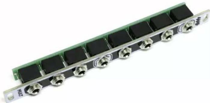
This guide is for building the Passive Mult (PM), a two channel multiple. The PM allows you to split a single signal into multiple copies. The PM can work in a single one-to-six multiple or as a dual one-to-three multiple. Since the device is passive, it can also be used to combine signals (three-to-one, or six-to-one). This is a beginner level kit, with only basic tools and soldering experience necessary.
Tools Needed:
- Soldering iron, solder
- 5/16" socket driver (optional: pliers will work if you're careful)
Step 1: Insert Jacks/Prep Mounting
Install the eight jacks to the green PCB. The jacks should be inserted on the side with the white rectangles and circles. Tip: Feed the longer bent pin in first, then push the other two pins in snugly. Push each jack down so it's flush against the PCB. See photos below.

natural_image
Close-up of hands holding a green printed circuit board with circular pads, against a white background (no text or symbols visible)
natural_image
Close-up of a green printed circuit board with black connectors and metallic threaded pins, no visible text or symbols.Step 2: Install Panel
A. Double-check that the jacks are flush to the PCB (see above photo). Take the black and white panel and gently lower it down on the PCB. Wiggle it slightly so that it fits over the jacks.
B. When the panel is on, hold everything together with one hand while putting a nut on the center jack with your other hand (see photo on left). This is tricky and you may drop the nut a few times: don't worry, this is the hardest part. Tighten the nut as tight as you can with your hands (don't use a tool yet).
C. Install the rest of the nuts on the jacks. First tighten each one by hand. Then go back and tighten all the nuts another 1/8 turn using a 5/16" socket wrench or pliers (be careful not the scratch the pane!!).
D. Flip it over and make sure there are no gaps between the jack and the PCB. Also make sure the PCB is parallel with the panel. Be careful to hold the PCB and panel at the same time, as the PCB can still slip off the jacks.

natural_image
Close-up of hands installing a circuit board with metal connectors and a metal ruler (no visible text or symbols)Step 3: Soldering
A. Place the unit on a hard surface or in vise to solder so that the panel is facing the floor and the PCB is facing the ceiling. See photo below.
B. Do a final check to make sure each jack is flush to the PCB
C. Solder all the jack leads.

natural_image
Close-up of hands using a soldering iron to adjust a green printed circuit board (no visible text or symbols)Step 4: Finish
Go back and tighten all the nuts another 1/8 turn using a socket wrench or pliers (carefully, the panel scratches easily).
And there you have it, a completed 4ms Passive Mult! This module requires no power, so all that's left is to install in your Eurorack system with the supplied 3mm screws. Enjoy!
natural_image
Close-up of a green circuit board with black connectors and metallic connectors (no visible text or symbols)
Brand : 4ms
Model : Passive Multiple
Category : Kibodi