
NMX-PRS-N7142 - Unspecified AMX - Free user manual and instructions
Find the device manual for free NMX-PRS-N7142 AMX in PDF.


| Product Type | Network Video Encoder |
| Brand | AMX |
| Model | NMX-PRS-N7142 |
| Dimensions (L x W x H) | 20 x 15 x 4 cm |
| Weight | 0.5 kg |
| Power Supply | PoE (802.3af) or 12V DC, 1A |
| Power Consumption | 10 W max |
| Video Input | HDMI 2.0 |
| Video Output | Streaming over IP (H.264/H.265) |
| Maximum Resolution | 3840 x 2160 @ 60 Hz (4K UHD) |
| Audio Input | Embedded HDMI or analog 3.5 mm |
| Network Interface | 1x Gigabit Ethernet RJ-45 |
| Supported Protocols | RTSP, RTMP, HLS, MPEG-TS |
| Control Interface | RS-232, IR, TCP/IP |
| Mounting | Desktop or rack mount kit (optional) |
| Operating Temperature | 0°C to 40°C |
| Humidity | 10% to 90% non-condensing |
| Certifications | FCC, CE, RoHS |
| Cleaning | Wipe with a dry, soft cloth. Do not use liquids. |
| Safety | Install in a well-ventilated area away from heat sources. |
| Spare Parts | Power adapter, mounting brackets, IR emitter |
| Repairability | Contact authorized service center for repairs. |
| Warranty | 3 years limited |
| Included Accessories | Quick start guide, CD with manual, power supply |
Frequently Asked Questions - NMX-PRS-N7142 AMX
User questions about NMX-PRS-N7142 AMX
0 question about this device. Answer the ones you know or ask your own.
Ask a new question about this device
Download the instructions for your Unspecified in PDF format for free! Find your manual NMX-PRS-N7142 - AMX and take your electronic device back in hand. On this page are published all the documents necessary for the use of your device. NMX-PRS-N7142 by AMX.
USER MANUAL NMX-PRS-N7142 AMX
IMPORTANT SAFETY INSTRUCTIONS
- READ these instructions.
- KEEP these instructions.
- HEED all warnings.
- FOLLOW all instructions.
- DO NOT use this apparatus near water.
-
CLEAN ONLY with dry cloth.
-
DO NOT block any ventilation openings. Install in accordance with the manufacturer's instructions.
- DO NOT install near any heat sources such as radiators, heat registers, stoves, or other apparatus (including amplifiers) that produce heat.
- DO NOT defeat the safety purpose of the polarized or grounding type plug. A polarized plug has two blades with one wider than the other. A grounding type plug has two blades and a third grounding prong. The wider blade or the third prong are provided for your safety. If the provided plug does not fit into your outlet, consult an electrician for replacement of the obsolete outlet.
- PROTECT the power cord from being walked on or pinched, particularly at plugs, convenience receptacles, and the point where they exit from the apparatus.
- ONLY USE attachments/accessories specified by the manufacturer.

-
USE ONLY with a cart, stand, tripod, bracket, or table specified by the manufacturer, or sold with the apparatus. When a cart is used, use caution when moving the cart/apparatus combination to avoid injury from tip-over.
-
UNPLUG this apparatus during lightning storms or when unused for long periods of time.
-
REFER all servicing to qualified service personnel. Servicing is required when the apparatus has been damaged in any way, such as power-supply cord or plug is damaged, liquid has been spilled or objects have fallen into the apparatus, the apparatus has been exposed to rain or moisture, does not operate normally, or has been dropped.
-
DO NOT expose this apparatus to dripping or splashing and ensure that no objects filled with liquids, such as vases, are placed on the apparatus.
-
To completely disconnect this apparatus from the AC Mains, disconnect the power supply cord plug from the AC receptacle.
-
Where the mains plug or an appliance coupler is used as the disconnect device, the disconnect device shall remain readily operable.
-
DO NOT overload wall outlets or extension cords beyond their rated capacity as this can cause electric shock or fire.

The exclamation point, within an equilateral triangle, is intended to alert the user to the presence of important operating and maintenance (servicing) instructions in the literature accompanying the product.

The lightning flash with arrowhead symbol within an equilateral triangle is intended to alert the user to the presence of uninsulated "dangerous voltage" within the product's enclosure that may be of sufficient magnitude to constitute a risk of electrical shock to persons.

ESD Warning: The icon to the left indicates text regarding potential danger associated with the discharge of static electricity from an outside source (such as human hands) into an Integrated circuit, often resulting in damage to the circuit.
WARNING: To reduce the risk of fire or electrical shock, do not expose this apparatus to rain or moisture.
WARNING: No naked flame sources - such as candles - should be placed on the product.
WARNING: Equipment shall be connected to a MAINS socket outlet with a protective earthing connection.
WARNING: To reduce the risk of electric shock, grounding of the center pin of this plug must be maintained.
COPYRIGHT NOTICE
AMX© 2018, all rights reserved. No part of this publication may be reproduced, stored in a retrieval system, or transmitted, in any form or by any means, electronic, mechanical, photocopying, recording, or otherwise, without the prior written permission of AMX. Copyright protection claimed extends to AMX hardware and software and includes all forms and matters copyrightable material and information now allowed by statutory or judicial law or herein after granted, including without limitation, material generated from the software programs which are displayed on the screen such as icons, screen display looks, etc. Reproduction or disassembly of embodied computer programs or algorithms is expressly prohibited.
LIABILITY NOTICE
No patent liability is assumed with respect to the use of information contained herein. While every precaution has been taken in the preparation of this publication, AMX assumes no responsibility for error or omissions. No liability is assumed for damages resulting from the use of the information contained herein. Further, this publication and features described herein are subject to change without notice.
AMX WARRANTY AND RETURN POLICY
The AMX Warranty and Return Policy and related documents can be viewed/downloaded at www.amx.com.
ESD WARNING

To avoid ESD (Electrostatic Discharge) damage to sensitive components, make sure you are properly grounded before touching any internal materials. When working with any equipment manufactured with electronic devices, proper ESD grounding procedures must be followed to make sure people, products, and tools are as free of static charges as possible. Grounding straps, conductive smocks, and conductive work mats are specifically designed for this purpose.
Anyone performing field maintenance on AMX equipment should use an appropriate ESD field service kit complete with at least a dissipative work mat with a ground cord and a UL listed adjustable wrist strap with another ground cord

WARNING: Do Not Open! Risk of Electrical Shock. Voltages in this equipment are hazardous to life. No user-serviceable parts inside. Refer all servicing to qualified service personnel. Place the equipment near a main power supply outlet and make sure that you can easily access the power breaker switch.
WARNING: This product is intended to be operated ONLY from the voltages listed on the back panel or the recommended, or included, power supply of the product. Operation from other voltages other than those indicated may cause irreversible damage to the product and void the products warranty. The use of AC Plug Adapters is cautioned because it can allow the product to be plugged into voltages in which the product was not designed to operate. If the product is equipped with a detachable power cord, use only the type provided with your product or by your local distributor and/or retailer. If you are unsure of the correct operational voltage, please contact your local distributor and/or retailer.
FCC AND CANADA EMC COMPLIANCE INFORMATION:
This device complies with part 15 of the FCC Rules. Operation is subject to the following two conditions:
(1) This device may not cause harmful interference, and (2) this device must accept any interference received, including interference that may cause undesired operation.
NOTE: This equipment has been tested and found to comply with the limits for a Class A digital device, pursuant to part 15 of the FCC Rules. These limits are designed to provide reasonable protection against harmful interference in a commercial environment. This equipment generates, uses and can radiate radio frequency energy and, if not installed and used in accordance with the instructions, may cause harmful interference to radio communications. However, there is no guarantee that interference will not occur in a particular installation. If this equipment does cause harmful interference to radio or television reception, which can be determined by turning the equipment off and on, the user is encouraged to try to correct the interference by one or more of the following measures:
•Reorient or relocate the receiving antenna.
- Increase the separation between the equipment and receiver.
- Connect the equipment into an outlet on a circuit different from that to which the receiver is connected.
- Consult the dealer or an experienced radio/TV technician for help.
Approved under the verification provision of FCC Part 15 as a Class A Digital Device.
Caution: Changes or modifications not expressly approved by the manufacturer could void the user's authority to operate this device.
CAN ICES-3 (B)/NMB-3(B).
EU COMPLIANCE INFORMATION:
Eligible to bear the CE mark; Conforms to European Union Low Voltage Directive 2006/95/EC; European Union EMC Directive 2004/108/EC; European Union Restriction of Hazardous Substances Recast (RoHS2) Directive 2011/65/EU; European Union WEEE (recast) Directive 2012/19/EU; European Union Radio and Telecommunications Terminal Equipment (R&TTE) Directive 1999/5/EC.
WEEE NOTICE:

This appliance is labeled in accordance with European Directive 2012/19/EU concerning waste of electrical and electronic equipment (WEEE). This label indicates that this product should not be disposed of with household waste. It should be deposited at an appropriate facility to enable recovery and recycling.
Table of Contents
Chapter 1: Introducing Your New N7142 Room Switcher 6
Product Overview 6
Hardware Overview 7
Chapter 2: Installing the N7142 9
Physical Installation 9
Initial Setup 9
Chapter 3: Room Switcher Configuration Options 14
Quick Setup Page 15
User Presets Page 16
Input Page 17
Output Page 18
Networking Page 19
Audio Page 20
Advanced Page 21
Device Info Page 22
Chapter 4: Room Switcher Detailed Configuration Options....23
Settings Page 24
Front Panel Page 30
Switcher Page 32
Audio Page 34
IR Page 41
N-Act Page 42
Serial Page 43
Security Page 44
Logs Page 45
NetLinx Page 45
Users Page 47
Panel Builder Page 48
Chapter 5: Troubleshooting 49
Appendix A: Panel Builder 50
Beginning a Panel Builder Project.... 50
Top Ribbon Option Descriptions 52
Project Pane Option Descriptions 53
Tools Pane Option Descriptions 57
Appendix B: NetLinx Control 59
Introduction 59
NetLinx Configuration Using the Unit's Webpage 59
Batch Configurations Using N-Able 60
Encoder/Decoder Commands 61
Windowing Processor Commands 65
Network Video Recorder Commands 67
Audio over IP Transceiver Commands 72
N-Command 73
Presentation Switcher 73
Appendix C: Minimum Network Requirements 74
Chapter 1: Introducing Your New N7142 Room Switcher
Product Overview
The SVSI N7142 Presentation Switcher provides low-latency Networked AV distribution. Designed for professional AV integration, this unit has six local video inputs, two video outputs, and two available slots for any SVSI networked AV cards to support the best codec for the application.
The four 4K60 HDMI inputs and two VGA inputs can be independently switched between two scaled HDMI outputs. Each of the two outputs has a mirrored HDMI port so that the output can be sent to an Encoder card, a second display, or other video distribution equipment.
The N7142 also has extensive audio support, with a built-in DSP and 60W stereo amplifier capable of operating in 4Ω/8Ω, 70V, or 100V modes. In addition to audio from the HDMI inputs, the N7142 has six independent balanced stereo inputs and two independent microphone inputs with phantom power.
There are two models of the N7142. The NMX-PRS-N7142 is the base Presentation Switcher, with two available Networked AV slots that can be populated with Encoder and Decoder cards as required by the application. The NMX-PRS-N7142-23 is an identical Presentation Switcher, pre-populated with one N2312 Encoder card and one N2322 Decoder card, making it perfect for cost-sensitive 4K video distribution applications.
Common Applications
While the N7142 is priced right for any design requiring the need of a presentation switcher, the two available Networked AV card slots make it the perfect presentation switcher for active learning environments, or campuses where overflow support is required. Integrating the N7142 into a classroom is extremely simple, requiring only web page configuration to set up the system. The N7142 has Panel Builder built-in so that mobile device UIs can be created to control the switcher from anywhere in the room (assuming that the mobile device has wireless access to the same network that the N7142 is connected to). The built-in, six-port managed switch allows the N7142 and the two Networked AV cards to be connected to the LAN with a single network drop.
Features include:
- 4K60 4:4:4 Video Switching – Switch and display 4K video sources without compromising video quality.
- HDMI 2.0 and HDCP 2.2 Support – By incorporating HDMI 2.0 and HDCP 2.2, the N7142 is compatible with all the latest 4K sources and displays.
- Integrated Networked AV Slots and Gigabit Ethernet Switch – Distribute video in active learning environments or to overflow locations using built-in Networked AV technology. The Networked AV card slots are designed to support the existing Encoder and Decoder cards. The built-in switch provides PoE+ on three of its six ports.
- Built-in Audio Amplifier with 4Ω/8Ω, 70V, and 100V Modes – Having built-in support for all three amplifier modes simplifies purchasing and sparing decisions.
- Front Panel Control – Provides a cost effective, simple solution for selecting inputs without the need for an auxiliary control system.
- Panel Builder Built-In – Operate the N7142 using a tablet from anywhere in the room.
TABLE 1 Product Specifications
| Product Specifications | |
| Models Available: | NMX-PRS-N7142: Card slots are available for appropriate N-Series Encoder/Decoder cards to be installed (not included).NMX-PRS-N7142-23: Card slots are pre-populated with N2312 Encoder and N2322 Decoder cards. |
| Power Requirements: | Input: 2.4 Amp @ 120V ACOutput: Supports up to three PoE+ network devices. |
| Dimensions (HWD): 3.5" x 17.5" x 13" (8.9 x 44.5 x 33 cm)With mounting wings, width is 19". | |
| Weight: 19.5 lbs (8.85 kg) | |
| Certifications: FCC/CE/ICES-003/UL | |
| Environmental: Temperature: 32° to 104°F (0° to 40°C)Humidity: 10% to 90% RH (non-condensing) | |
| Installation: Standalone or rack-mount (mounting ears included) | |
NOTE: The video outputs only play audio from the selected HDMI input. The audio going to the video output is not selectable.
Hardware Overview
Refer to the following figures (front and rear panel drawings) and the corresponding tables (on page 7 and page 8) for hardware details.

1) Presets Buttons
2) Video Select Buttons
3) Video Inputs LEDs
4) Video Outputs LEDs
5) Menu Button
6) Arrow Buttons
7) Enter Button
8) Volume Dial
FIG. 1 N7142 Room Switcher Front Panel
TABLE 2 Front Panel Descriptions
| Connector/Indicator | Description |
| PRESETS buttons | Press and hold (30 seconds) to save the current system configuration, including the resolutions of the output ports and the video selection. The button lights up (flashes) when save is successful. Press (no hold) to recall a saved configuration. |
| VIDEO SELECT buttons | Choose which video Input (1-6) is displayed. The top row of buttons sends the video toVIDEO OUTPUT 1.The bottom row sends the video toVIDEO OUTPUT 2. |
| VIDEO INPUTS/OUTPUT LEDs | On solid green when there is an active connection. |
| MENU and arrow buttons | PressMENUto access the quick setup menu options for basic configuration. The menu will display on the screen connected to aVIDEO OUTPUT. Use the corresponding arrow and ENTER buttons to navigate the quick setup menu and make selections. |
| VOLUME control | Controls the volume of the selected audio output sent through the amplifier. |

1) 12VDC Output
2) Networked AV Card Slots
3) 12VDC Output
4) Audio Inputs/Outputs
5) Video Inputs
6) Video Outputs
7) Built-In Switch
FIG. 2 N7142 Room Switcher Rear Panel
TABLE 3 Rear Panel Highlights
| Connector/Indicator Description | |
| 12V 2A outputs | 12 Volt DC power output. Can be used to power the Networked AV Cards (if PoE is not being used). |
| Networked AV Card Slots Dependent on model type.NMX-PRS-N7142: Slots can be populated with Encoder and Decoder cards as required by the application.NMX-PRS-N7142-23: Slots are pre-populated with one N2312 Encoder card and one N2322 Decoder card. | |
| AUDIO INPUTS/OUTPUTS | Extensive audio selections are supported including a built-in DSP and 60W stereo amplifier capable of operating in 4Ω/8Ω, 70V, or 100V modes. In addition to audio from the HDMI inputs, the unit has six independent balanced stereo Inputs and two independent microphone Inputs with phantom power. |
| VIDEO INPUTS (1-6) | Four 4K60 HDMI inputs and two VGA inputs. These can be independently switched between the two independently scaled HDMI outputs using theVIDEO SELECTbuttons on the front panel. |
| VIDEO OUTPUTS | Two 4K60 HDMI outputs, each with its own mirrored HDMI port. This allows the output to be sent to an Encoder card, a second display, or other video distribution equipment.• Channels 1A and 1B are a mirrored pair.• Channels 2A and 2B are a mirrored pair. |
| 6-port Gbps Switch | Six-port Gbps switch (with PoE+ on the left three ports). Used for interconnection of AV cards and the main network. |
NOTE: : Both microphone inputs have Acoustic Echo Cancellation (AEC) turned on by default. AEC can be turned off through the API.
Chapter 2: Installing the N7142
Physical Installation
Follow the steps below to connect the N7142 to the network.
- Mount the unit into a standard 19-inch server rack cabinet using the mounting ears included in shipment.
NOTE: Maintain a minimum of 2.5 inches (6.4 cm) of clear space between the side edge of the chassis and the side wall of the cabinet. Ensure the chassis air intake and exhaust vents are not obstructed in any way.
-
Connect a monitor (that supports 1080p60) to one of the VIDEO OUTPUT connectors on the rear of the unit.
-
If networked AV cards are installed:
-
Connect the network cables from the cards to the built-in switch. See Note below.
- Connect the HDMI output on the installed Decoder to an N7142 HDMI input.
- Connect the HDMI input on the installed Encoder to an N7142 HDMI output.
NOTE: If the AV card is connected to one of the three PoE+ ports, it will be powered automatically once the network connection is established. If not, then connect the two-pin phoenix adapter from the 12VDC output connector of the N7142 to the 12VDC input connector on the card.
CAUTION: Do not run wiring that is connected to a PoE PSE port outside of the building where the PSE resides. It is for intra-building use only.
- Connect all other video sources, displays, etc. as necessary for your application.
CAUTION: Do not populate the 60W stereo, 70V 100W and 100V 100W amplifier outputs with uninsulated parts or terminals or any bare wiring. Avoid touching these outputs when the unit is powered.
- Apply power to the unit using the power cable provided.
Initial Setup
Follow the steps below for initial software setup of the N7142.
-
Once the unit completes the boot up process and the attached monitor displays the AMX logo, press the MENU button (on the N7142's front panel) to access the On-Screen Display (OSD) setup menu. The Quick Setup page displays (see Figure 3).
NOTE: The OSD menu options are described in detail in the Room Switcher Configuration Options chapter beginning on page 14. -
Use the corresponding arrow and ENTER keys (on the front panel) to assign the N7142 a Name.

FIG. 3 Set a Name for the Unit
- Navigate to the Networking page (see Figure 4). For both the N7142 and the Internal Switch, select AUTOIP, DHCP, or STATIC from the Network Mode drop-down menu and then configure the other network settings as appropriate.
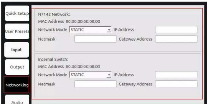
FIG. 4 Configure Network Settings
Internal Switch Configuration
Once the switch's IP address has been configured, you can access all switch settings via your web browser. Enter the switch's IP address into your browser window. When the login screen appears, enter admin as the username. Upon successful login, the Port State Overview page will display (shown in Figure 5).
NOTE: No password is required initially, but you should create one immediately for security purposes (select Configuration > Security > Switch > Users).

FIG. 5 Internal Switch Main Page
You can now configure the switch as required for your network setup. Some examples follow.
To enable IGMP Query for the internal switch, follow these steps:
-
Select Configuration > IPMC > IGMP Snooping from the menu at the left of the screen.
-
Check the Snooping Enabled box (as shown in Figure 6).
NOTE: The options you will need for setting up a new VLAN can also be found in this area of the switch's options (Configuration >IPMC >IGMP Snooping >VLAN Configuration). For more information, click the ? icon at the top-right of the screen.

FIG. 6 Internal Switch IGMP Snooping Page
To configure the internal switch for 802.1x, follow these steps:
- Make sure the switch's IP address is in the same subnet as the Radius server.
- Select Configuration > Spanning Tree > CIST Ports (as shown in Figure 7).
- Uncheck STP Enabled for each port.

FIG. 7 CIST Port Configuration Page
- Select Configuration > Security > AAA > Radius (as shown in Figure 8).
- Click Add New Server and enter the server Hostname/Secret Key/etc.
- Click Save.

FIG. 8 Radius Server Configuration Page
- Select Configuration > Security > Network > NAS (as shown in Figure 9).
- Under System Configuration, change the Mode to Enabled.
- Under Port Configuration, change the Admin State of the desired port to any of the 802.1x options (Port-based, Single, Multi, etc.).
- Click Save.

FIG. 9 Network Access Server Configuration Page
- To save the full configuration, select Maintenance > Configuration > Save startup-config.
NOTE: For more extensive Switch Configuration information, click the ? icon at the top-right of the screen.
Advanced Configuration
For more advanced N7142 Switcher configuration options, enter the unit's IP address into your web browser. When prompted, enter the default username and password (admin and password). The Switcher Configuration page displays (see Figure 10). From here, you can view the status of the N7142's Inputs and Outputs as well as make minor configuration adjustments. Click the Settings link at the top of the page to access the more detailed configuration options (which are described in the Room Switcher Detailed Configuration Options chapter, beginning on page 23).

FIG. 10 Initial Switcher Configuration Screen
Chapter 3: Room Switcher Configuration Options
This chapter defines the N7142 Room Switcher configuration options accessible via the On-Screen Display (OSD) setup menu. Once the unit completes the boot up process and the attached monitor displays the AMX logo, press the MENU button (on the front panel of the unit) to access this interface. The Quick Setup page (shown in Figure 11) displays first.
Use the corresponding arrow and ENTER keys (on the front panel) to navigate and make changes to the setup.
For ease of navigation, this chapter is organized to reflect the OSD interface. Figure 11 shows the navigation bar and provides hot links to the chapter's sections which describe each main page.

FIG. 11 Section Links
Quick Setup Page
Click the Quick Setup link in the left menu bar to access the page shown in Figure 12. See Table 4 for option descriptions.

FIG. 12 Quick Setup Page
TABLE 4 Quick Setup Page Options
| Option Description | |
| Name | Enter a user-friendly name for the unit. More descriptive names in this field help you organize and manage the N-Series system efficiently. Names based on the unit's location and function are very useful. Some good examples areLobby-Left-VGA(for left side of lobby, VGA input) orCR201-HDMI(for Conference Room 201, HDMI Input). Keep in mind the matrices are organized alphanumerically. |
| IP Address | View the current IP address configured for the N7142. Click theChangebutton to make adjustments if necessary. |
| Output Resolution | Select the output resolution of the video to be transmitted to the video output device (e.g., LCD). |
User Presets Page
Click the User Presets link in the left menu bar to access the page shown in Figure 13. See Table 5 for option descriptions.
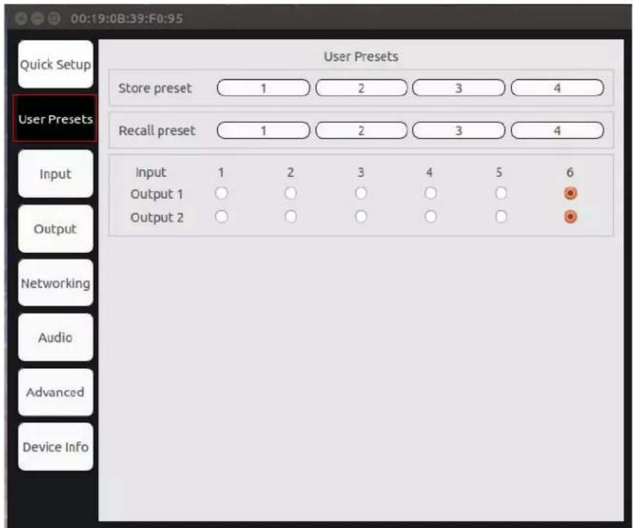
FIG. 13 User Presets Page
TABLE 5 User Presets Page Options
| Option Description | |
| Store Preset | Click to save the current configuration to one of the preset numbers (1-4). |
| Recall Preset | Click to recall the configuration saved to one of the preset numbers (1-4). |
| Input/Output matrix | Click to switch video to a different output. Choose the common cell to route a chosen video input (1-6) to either of the video outputs. The top row of buttons sends the video toVIDEO OUTPUT 1. The bottom row sends the video toVIDEO OUTPUT 2. |
Input Page
Click the Input link in the left menu bar to access the page shown in Figure 14. Current AV input status information is displayed here.

FIG. 14 Input Page
Output Page
Click the Output link in the left menu bar to access the page shown in Figure 15. See Table 6 for option descriptions.

FIG. 15 Output Page
TABLE 6 Output Page Options
| Option Description | |
| HDMI Output 1/2 | Select the output Resolution and Colorspace settings of the video to be transmitted to the video output device (e.g., an LCD screen). |
| Audio Line 1/2 | Mute/unmute the selected audio or choose to route an audio source to the audio output. Choices for routing include microphone 1 and 2, hdmi2, hdmi3, hdmi5, hdmi6, and analog 1 through 6.Custom displays if the user has specified their own audio configuration on the web page. |
| Amplified Audio | Mute/unmute the amplified audio or choose to route an audio source to the audio output. Choices for routing include microphone 1 and 2, hdmi2, hdmi3, hdmi5, hdmi6, and analog 1 through 6.Custom displays if the user has specified their own audio configuration on the web page. |
Networking Page
Click the Networking link in the left menu bar to access the page shown in Figure 16. See Table 7 for option descriptions.

FIG. 16 Networking Page
TABLE 7 Networking Page Options
| Option Description | |
| N7142 Network: These settings apply to the N7142 Room Switcher. | |
| MAC Address Displays the MAC address of the network interface. | |
| Network Mode | Configure the IP address mode. When set to AUTO IP, an IP Address in the range of 169.254.xxx.xxx with Netmask of 255.255.0.0 and Gateway address of 169.254.1.1 will be automatically assigned to the N7142 Room Switcher by the control software. When set to DHCP, an IP Address in the range of the DHCP server on the network will be automatically assigned to the N7142 Room Switcher. When set to STATIC, an IP address, Netmask, and Gateway address must be manually entered.NOTE: DHCP is the default setting. However, using DHCP beyond initial setup is generally not recommended. If the device is set to DHCP and falls to receive an address from the DHCP server in time, it will revert back to the AUTO IP address (169.254.xxx.xxx) until the unit is rebooted. |
| IP Address | View the current IP address. When in STATIC mode, enter a new IP address into this field. |
| Netmask | View the current Netmask. When in STATIC mode, enter a new Netmask into this field. |
| Gateway Address | View the current Gateway address. When In STATIC mode, enter a new Gateway address into this field. |
| Internal Switch: These setting apply to the N7142's built-in, six-port switch. | |
| MAC Address Displays the MAC address of the internal switch. | |
| Network Mode | Configure the IP address mode. Only STATIC and DHCP modes are supported. See the N7142's Network Mode setting description earlier in this table for more considerations. To log in to the internal switch's configuration menus, enter its IP address into your browser. When prompted, enter the username and password. The default username is admin with no password. |
| IP Address | View the current IP address. When in STATIC mode, enter a new IP address into this field. |
| Netmask | View the current Netmask. When in STATIC mode, enter a new Netmask into this field. |
| Gateway Address | View the current Gateway address. When in STATIC mode, enter a new Gateway address into this field. |
Audio Page
Click the Audio link in the left menu bar to access the page shown in Figure 17. See Table 8 for option descriptions.
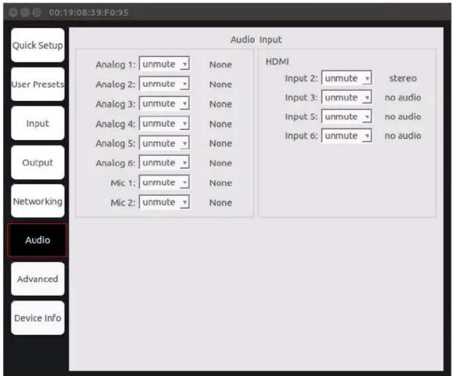
FIG. 17 Audio Page
TABLE 8 Audio Page Options
| Option Description | |
| Analog 1-6 Choose to mute/unmute the selected audio. | |
| Mic 1-2 Choose to mute/unmute the microphone. | |
| HDMI Input 2, 3, 5, 6 | Choose to mute/unmute the audio of the selected input. |
Advanced Page
Click the Advanced link in the left menu bar to access the page shown in Figure 18. See Table 9 for option descriptions.

FIG. 18 Advanced Page
TABLE 9 Advanced Page Options
| Option Description | |
| Factory Restore | Click to restore the device to the original factory settings. This resets everything except the IP address (including name, stream number, serial settings, etc.). |
| Reboot | Click to begin a software reboot. This command does not initiate a full power cycle and does not affect the current configuration. |
NOTE: When either of these options is selected, the OSD disappears and the operation is performed.
Device Info Page
Click the Device Info link in the left menu bar to access the page shown in Figure 19. Here you can view release and product version information as well as the current internal temperature of the N7142 (in degrees Celsius).

FIG. 19 Device Info Page
Chapter 4: Room Switcher Detailed Configuration Options
This chapter defines N7142 Room Switcher configuration options. Access these options by entering the unit's IP address into your browser. The default username/password is admin and password).
For ease of navigation, this chapter is organized to reflect the webpage's graphical user interface (GUI). From any main page in the GUI, you can access all other main pages by clicking the links in the top navigation bar. Figure 20 shows the navigation bar and provides hot links to the chapter's sections which describe each main page.

FIG. 20 Section Links
Settings Page
Click the Settings link at the top of any of the main web pages to access the page shown in Figure 21. This page is divided into several sections and also has links to other dialog boxes for additional configuration options. Refer to the following sections for detailed descriptions:
• Room Switcher Setup Section on page 25
• Network Setup Section on page 27
• Status Section on page 28
• Change Password Section on page 29
• LDAP Section on page 29
• Software Section on page 30

FIG. 21 Settings Page
Room Switcher Setup Section
The Room Switcher Setup section of the Settings page is shown in Figure 22. Options are described in Table 10.

FIG. 22 Room Switcher Setup Section
TABLE 10 Settings Page: Room Switcher Setup Section
| Option Description Notes | ||
| Device Name | Enter a user-friendly name for the unit. | More descriptive names in this field help you organize and manage the N-Series system efficiently. Names based on the unit's location and function are very useful. Some good examples areLobby-Left-VGA(for left side of lobby, VGA input) orCR201-HDMI(for Conference Room 201, HDMI input). Keep in mind the matrices are organized alphanumerically. |
| Output 1 and 2 Mode Select the output resolution of the video to be transmitted to the video output device (e.g., LCD). | This setting affects the scaler video output. | |
| Output 1 and 2 Colorspace | Select the output colorspace for the video output. | You can set each of the outputs toRGB444,YUV422,orYUV444colorspaces. This setting affects the scaler video output. |
| Option | Description | Notes |
| Output 1 and 2 Video Mute | Enable to mute the video. If enabled, the video output displays black instead of live video. | |
| Cancel Click to return all controls to the last saved configuration. | This button affects all Room Switcher Setup controls that are listed above it. | |
| Save | Click to accept changes made to the controls. | This button affects all Room Switcher Setup controls that are listed above it. |
| RS232 Baud Rate drop-down | Select the baud rate, data bits, parity, and stop bit settings for the RS232 serial interface. | |
| Relay 1/2 interlock If enabled, does not allow both relays 1 and 2 to be closed at the same time. | ||
| Relay 1/2 state Opens or closes the external relays 1 and 2. If interlock is on, closing 1 opens 2 and vice versa. | ||
| Relay 3/4 interlock | If enabled, does not allow both relays 3 and 4 to be closed at the same time. | |
| Releay 3/4 state Opens or closes the external relays 3 and 4. If interlock is on, closing 3 opens 4 and vice versa. | ||
| GPIO 1-4 Configures the external general purpose IO pins as input or output. If selected to input, displays the GPIO state. If selected to output, allows the user to set the state. | ||
| Settings Lock Enable to lock the N7142 unit settings. | ||
| Gratuitous ARP Enable the Room Switcher to send a periodic Address Resolution Protocol (ARP) packet to the network. | ||
| ARP Interval (secs) Determine how often (in seconds) the unit transmits gratuitous ARP packets. | ||
| Unsolicited Status Enable the Room Switcher to send a periodic status packet to the Send Status Address described below. | ||
| Send Status Address | When Unsolicited Status is enabled, the Room Switcher sends a periodic status packet to the IP address specified here. | |
| Status Interval (secs) Determine how often (in seconds) the unit transmits status packets. | ||
| Discovery Packet Transmit | Enable the N-Series multicast discovery service (which is used to identify units). | |
| Discovery Interval (secs) | Determine how often (in seconds) the unit transmits discovery packets. | |
| Serial Master Enable | Enable this device to be the master to the designated client. | Once set in master mode, outside serial commands will be ignored. |
| Serial Client Address | Enter the IP address of the serial client device. | |
| IR Command Holdoff Set the delay between IR command portions. The default setting is 25 ms. | IR commands are sent in two parts. This setting is the time (in milliseconds) between transmission of part one and part two. The second part of the command is inverted for confirmation purposes. | |
| IR Repeat Holdoff | Set the repeat delay between IR commands. The default setting is 90 ms. | This is the amount of time before a new command is sent. For example, when pressing and holding the volume button on a remote control, this is how long until the command is repeated. |
| Enable SNMP | Enable to allow the device to handle Simple Network Management Protocol (SNMP) queries. | |
| Cancel Click to return all controls to the last saved configuration. | This button affects all Room Switcher Setup controls that are listed above it. | |
| Save | Click to accept changes made to the controls. | This button affects all Room Switcher Setup controls that are listed above it. |
Network Setup Section
The Network Setup section of the Settings page is shown in Figure 23. Options are described in Table 11.

FIG. 23 Network Setup Section
TABLE 11 Settings Page: Network Setup Settings
| Option Description Notes | ||
| IP Mode | Configure the IP address mode. When set to AUTO IP, an IP Address in the range of 169.254.xxx.xxx with Netmask of 255.255.0.0 and Gateway address of 169.254.1.1 will be automatically assigned to the N2400 Room Switcher by the control software. When set to DHCP, an IP Address in the range of the DHCP server on the network will be automatically assigned to the N2400 Room Switcher. When set to STATIC, an IP address, Netmask, and Gateway address must be manually entered. | DHCP is the default setting. However, using DHCP beyond initial setup is generally not recommended. If the device is set to DHCP and fails to receive an address from the DHCP server in time, it will revert back to the AUTO IP address (169.254.xxx.xxx) until the unit is rebooted. |
| IP address View the current IP address of the N2400 Room Switcher. When in STATIC mode, enter a new IP address into this field. | ||
| Netmask | View the current Netmask of the N2400 Room Switcher. When in STATIC mode, enter a new Netmask Into this field. | |
| Gateway address | View the current Gateway address of the N2400 Room Switcher. When in STATIC mode, enter a new Gateway address Into this field. | |
| Manual DNS | Enable to override the DNS selection. | Allows you to enter manual DNS values. |
| DNS #1-#2 | Specifies the main servers for use of DNS. | |
| Ping Test | Test the connection by specifying an IP address or URL to ping. Click the Ping link to initiate the test. | |
| Trial Save | Click to initially save IP address changes. Once you log in to the unit using the new address, you will be able to confirm and accept the changes permanently. | |
| Switch Network Configure network switch settings for the N7142's built-in, six-port switch. | Once the switch's IP address has been configured, you can access all switch settings via your web browser.Enter theSwitch Network IPaddress into your browser window. When the login screen appears,enteradminas the username.Note: No password is required initially, but you should create one immediately for security purposes. | |
Status Section
The Status section of the Settings page is shown in Figure 24. Options are described in Table 12.
Status
Video Input 1 Status : Disconnected no source
Video Input 2 Status : Connected 1920x1080@60
Video Input 3 Status : Disconnected no source
Video Input 4 Status : Disconnected no source
Video Input 5 Status : Connected 3840x2160@60
Video Input 6 Status : Connected 1920x1080@60
HDMI Output 1a Status : Disconnected
HDMI Output 1b Status : Connected
HDMI Output 2a Status : Disconnected
HDMI Output 2b Status : Connected
Port 50001 Source IP: Disconnected
Port 50002 Source IP: Disconnected
Serial Source IP: Disconnected
Flush
Flush
Flush
FIG. 24 Status Section
TABLE 12 Settings Page: Status Section
| Option Description Notes | ||
| Video Input Status(1-6) | Indicates if a video source is plugged into input. The incoming video resolution is also reported here. | |
| HDMI Output Status(1a, 1b, 2a, 2b) | Indicates if monitor is plugged into output. | Displays Connected if the link is not HDCP protected.If the link is HDCP protected, displays either HDCP error or HDCP protected. |
| Source Resolution Indicates the video resolution of the currently connected video source. | ||
| Port 50001 Source IP Shows the IP address of the currently connected device or displays Disconnected if no connection exists. | Port 50001 can only accept a single external connection at a time. If a device is currently showing the port occupied (by a control system or other device), then other connections will be rejected.However, connection attempts from the same IP will override the current connection. | |
| Port 50002 Source IP Shows the IP address of the currently connected device or displays Disconnected if no connection exists. | Port 50002 can only accept a single external connection at a time. If a device is currently showing the port occupied (by a control system or other device), then other connections will be rejected.However, connection attempts from the same IP will override the current connection. | |
| Serial Source IP Shows the IP address of the currently connected device or displays Disconnected if no connection exists. | Only a single external connection can be accepted on the port. If a device is currently showing the port occupied (by a control system or other device), then other connections will be rejected. However, connection attempts from the same IP will override the current connection. | |
| Flush buttons | Disconnects all clients from the network port. | |
Change Password Section
To change the N7142 Room Switcher interface password, enter the current password in the field labeled Old Password, and enter a new password in the New Password and Confirm Password fields. Click Change PW to accept the new password.

FIG. 25 Change Password
NOTE: This password needs to match N-Able's stored password to allow auto-login using N-Able.
LDAP Section
The section of the Settings page shown in Figure 26 is displayed when you click the Configure LDAP link. Options are described in Table 13.
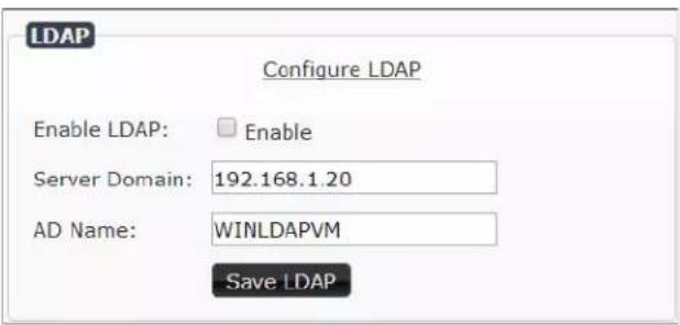
FIG. 26 LDAP Section
TABLE 13 Settings Page: LDAP Section
| Option Description | |
| Enable LDAP | Enable to configure the unit to access the network’s LDAP (lightweight directory access protocol) services. |
| Server Domain Enter | the IP address of the LDAP server. |
| AD Name Enter the | Active Directory’s name. |
| Save LDAP Click to | save settings made to this section. |
Software Section
The Software section of the Settings page is shown in Figure 27. Options are described in Table 14.
Software
Serial: N7142-15400000001
MAC address 00:19:0B:85:48:CE
Firmware Version: v00.01.17 (2/8/2018)
Web Version: 2/7/2018
Factory Restore
Reboot
FIG. 27 Software Section
TABLE 14 Settings Page: Software Section
| Option Description | |
| Serial Displays the serial number of the N2400 Room Switcher. | |
| MAC Address | Displays the MAC address of the network interface of the N2400 Room Switcher. |
| Firmware Version | Displays the date code for the currently running version of the N2400 Room Switcher internal firmware. |
| Web Version | Displays the date code for the currently running version of the web interface. |
| Factory Restore | Click to restore the device to the original factory settings. This resets everything except the IP address (including name, stream number, serial settings, etc.). |
| Reboot | Click to begin a software reboot. This command does not initiate a full power cycle and does not affect the current configuration. |
Front Panel Page
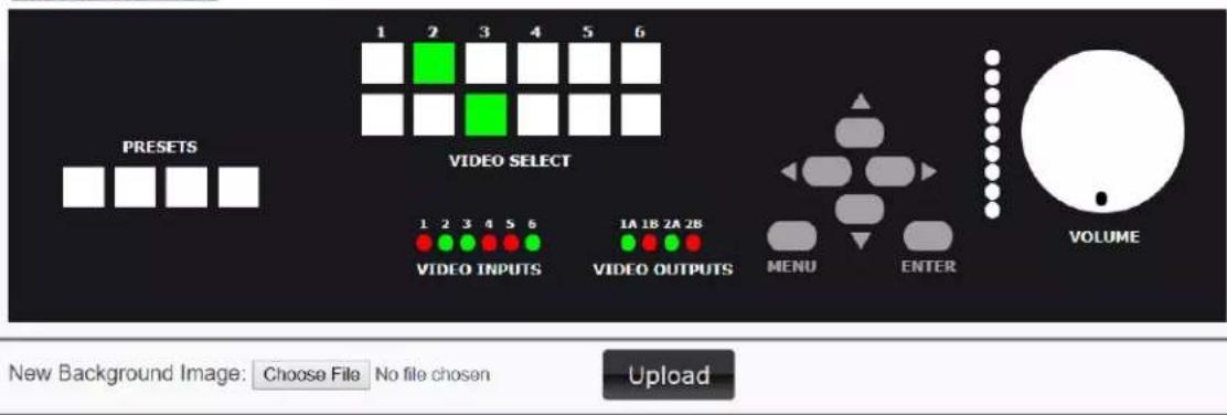
Click the Front Panel link at the top of any of the main web pages to access the page shown in Figure 28. This page emulates the operation of the buttons on the front of the unit for control of the device (with the exception of the Menu, Enter, and arrow buttons). See Table 15 for option descriptions.
AHG N7142 Room Switcher | Conference Rm 1 Switcher
Settings Front Panel Switcher Audio IR N-Act Serial Security Logs NetLinx Users Panel Builder
Room Switcher
AMX | 256.461.7143 | syssupport@harman.com
FIG. 28 Front Panel Page
TABLE 15 Front Panel Page Options
| Option Description | |
| VIDEO SELECT buttons | Click to switch video to a different output.Use theVIDEO SELECTbuttons to choose which video input (1-6) is displayed. The top row of buttons sends the video toVIDEO OUTPUT 1. The bottom row sends the video toVIDEO OUTPUT 2. |
| PRESET buttons | Click to select a preset. This will restore the device settings to a previously-saved configuration. Left-click and hold for 3-5 seconds to set a new preset configuration. |
| VIDEO INPUTS LEDs Green indicates video input connection. Status only. | |
| VIDEO OUTPUTS LEDs Green indicates monitor connection. Status only. | |
| MENU, ENTER, and arrow buttons | These buttons are functional on the unit’s front panel only. |
| VOLUME control | Controls the volume of the selected audio output sent through the amplifier. Click and drag to change volume. |
| New Background Image | Upload a new background image. This image will display if you select an input that doesn’t have any video. |
Switcher Page
Click the Switcher link at the top of the webpage to access the page shown in Figure 29. This is also the first page that displays when you log in to the unit's webpage. From here, you can view the status of the N7142's Inputs and Outputs as well as make minor configuration adjustments. Click the Settings link at the top of the page to return to the Settings page, gaining access to all other pages described in this chapter. See Table 16 for option descriptions.
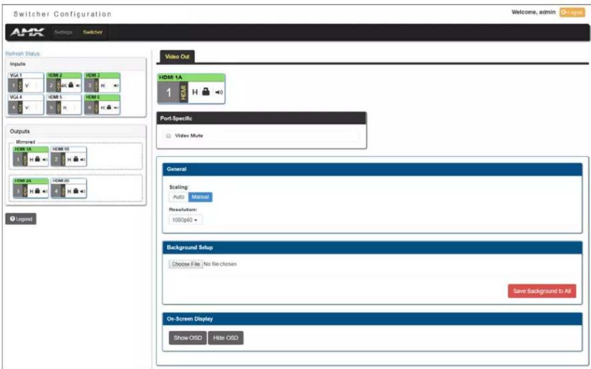
FIG. 29 Switcher Configuration Page
TABLE 16 Switcher Configuration Page Options
| Option Description | |
| Refresh Status button | Click to refresh the status for the N7142's video inputs and outputs. The current status is displayed below the button. Click theLegendbutton to see what the different status colors and icons represent. |
| Legend button | Click to display a legend which describes how the status of the inputs and outputs is represented (see Figure30on page 33). |
| Video In/Video Out | View/edit information for the currently selected input or output. |
| Port Specific | Enable/disable video mute on this port and its mirrored counterpart. Applies toVideo Outonly. |
| General | For Video Out:UnderScaling, chooseAutoto base scaling on the preference of the output device. ChooseManualto base scaling on the scaling resolution selected in theResolutiondrop-down menu. This setting affects the scaler video output for both mirrored outputs.For Video In:Displays the video resolution of the currently connected video source. |
| Background Setup | Upload a new background image. This uploaded image will display if you select an input that doesn't have any video. |
| On-Screen Display | Click to cause the OSD to display on the monitor connected to the N7142. Doing so from this screen can aid in unit identification.NOTE:When using the OSD for configuration changes, use the corresponding arrow and ENTER keys (on the N7142 front panel) to navigate the setup. |

FIG. 30 Audio/Video Status Legend
Audio Page
Click the Audio link at the top of any of the main web pages to access the page shown in Figure 31. See Table 17 for option descriptions. This page is divided into several sections and also has links to other dialog boxes for additional configuration options. Refer to the following sections for detailed descriptions:
- Inputs Tab on page 34
• Mixing Tab on page 35
• EQ & Outputs Tab on page 36
• Advanced Tab on page 38
Inputs Tab
The Inputs Tab section of the Audio page is shown in Figure 31. This section allows the user to control the input audio prior to it going into the mixers. Options are described in Table 17.

FIG. 31 Audio Page: Inputs Tab
TABLE 17 Audio Page: Inputs Tab
| Option Description | |
| Save Settings button Saves current configuration. | |
| Microphones Settings | |
| Mic 1/2 Volume (%) Controls microphone volume levels. | |
| Phantom Power 1/2 Enables power on microphone to be used for powered microphones | |
| Analog Settings | |
| Analog Volume 1-6 (%) Controls volume for the analog input channel. | |
| HDMI Settings | |
| Video Volume (2, 3, 5, 6) (%) | Controls the volume for the audio on the HDMI inputs. |
Mixing Tab
The Mixing Tab section of the Audio page is shown in Figure 32. Options are described in Table 18.
Use this page to configure mixes for the following outputs:
- The Line Out 1 and Line Out 2 columns correspond to the lineout audio outputs. These outputs are located on the rear of the unit, under the OUTPUTS labeling, and are marked 1 and 2.
- The Amp Out column corresponds to the active amplified audio output. These outputs are located on the rear of the unit, under the left card slot and are labeled 60W, 70V 100W, and 100V 100W.

FIG. 32 Audio Page: Mixing Tab
TABLE 18 Audio Page: Mixing Tab
| Option Description | |
| Save Settings button Saves current configuration. | |
| Line Out 1 Slider choices made in this column affect Line Out 1. | |
| Line Out 2 Slider choices made in this column affect Line Out 2. | |
| Amp Out 1 Slider choices made in this column affect the amplified output. | |
| Mic 1/2Analog 1-6Video 2, 3, 5, 6 | These sliders define how much of input audio is put into the specified mix. For example, if Mic1 is at .1, the mix will Include 10 percent of the microphone audio in the output. |
EQ & Outputs Tab
The EQ & Outputs Tab section of the Audio page is shown in Figure 33. Options are described in Table 19.
Use this page to configure settings for the following outputs:
- The Line Out 1 and Line Out 2 sections correspond to the lineout audio outputs. These outputs are located on the rear of the unit, under the OUTPUTS labeling, and are marked 1 and 2.
- The Amp Out section corresponds to the active amplified audio output. These outputs are located on the rear of the unit, under the left card slot and are labeled 60W, 70V 100W, and 100V 100W.
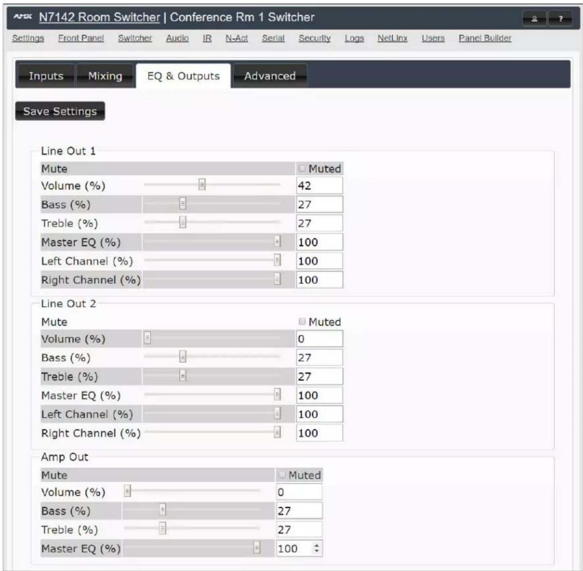
FIG. 33 Audio Page: EQ & Outputs Tab
TABLE 19 Audio Page: EQ & Outputs Tab
| Option Description | |
| Save Settings button Saves current configuration. | |
| Line Out 1/2 Settings | |
| Mute | Mutes the audio input for the lineout audio outputs. These outputs are located on the rear of the unit, under the OUTPUTS labeling, and are marked 1 and 2. |
| Volume (%) Sets audio output volume level. | |
| Bass/Treble (%) | Controls the frequency response of the audio output for high and low frequencies. |
| Master EQ (%) | Controls the master equalizer adjustment for all frequencies. |
| Option Description | |
| Left Channel (%) | Sets the mixer output left balance control on the specified output |
| Right Channel (%) | Sets the mixer output right balance control on the specified output |
| Amp Out Settings | |
| Mute | Mutes the audio output for the active amplified audio output. These outputs are located on the rear of the unit, under the left card slot and are labeled 60W, 70V 100W, and 100V 100W. |
| Volume (%) Sets amplified audio output volume level. | |
| Bass/Treble (%) | Controls the frequency response of the amplified audio output for high and low frequencies. |
| Master EQ (%) | Controls the master equalizer adjustment for all frequencies. |
Advanced Tab
The Advanced Tab section of the Audio page is shown in Figure 34. Options are described in Table 20.

FIG. 34 Audio Page: Advanced Tab
TABLE 20 Audio Page: Advanced Tab
| Option Description | |
| Save Settings button Saves current configuration. | |
| Mic Channel 1/2 Settings | |
| Highpass Filter | Enables filter to remove microphone bias and low frequency noises from speech picked up by the microphones. |
| Mono to Stereo | Duplicates the microphone audio to left/right stereo. |
| Feedback Cancel | Enables the microphone feedback canceler. |
| Feedback Cancel Attack Time (sec) | Sets the feedback canceler attack time in seconds. |
| Feedback Cancel Hold Time (sec) | Sets the feedback canceler hold time in seconds. |
| Feedback Cancel Min Gain (%) | Sets the minimum gain (maximum attenuation). This limits the amount of attenuation the FBC applies to a frequency band when oscillations are detected in that band. |
| Feedback Cancel Gain Inc Step (%) | Determines how quickly the gain returns to its normal state (no attenuation). |
| Feedback Cancel Gain Dec Step(%) | Determines how quickly the attenuation is applied. |
| Noise Reduction | Enables noise reduction. |
| Noise Reduction Level (%) | Sets the target level of the specified Noise Reduction processor to the given percentage value. |
| Analog 1-6 Settings | |
| Auto Duck | Enables analog input ducking. |
| Auto Duck Time (sec) | Sets the amount of time in seconds during which the RX signal stays ducked after the control signal becomes inactive. |
| Auto Duck Fade (ms) | Sets the amount of time in milliseconds during which the attenuation gain is gradually applied or removed. |
| Auto Duck Attenuation (%) | Sets the amount of attenuation to apply to the stereo RX signal when voice is detected in the control (microphone) audio stream. |
| Auto Duck Sensitivity (%) | Sets the threshold level above which the control signal is considered active and ducking attenuation should be applied. |
| Noise Reduction | Enables the analog input noise reduction. |
| Noise Reduction Level (%) | Sets the target level of the specified Noise Reduction processor to the given percentage value. |
| Audio Delay | Enables analog input delay. |
| Delay (ms) | Sets the number of samples by which the RX stereo stream should be delayed. |
| HDMI 2, 3, 5, and 6 Settings | |
| Auto Duck | Enables HDMI audio ducking feature. |
| Auto Duck Time (sec) | Sets the amount of time in seconds during which the RX signal stays ducked after the control signal becomes inactive. |
| Auto Duck Fade (ms) | Sets the amount of time in milliseconds during which the attenuation gain is gradually applied or removed. |
| Auto Duck Attenuation (%) | Sets the amount of attenuation to apply to the stereo RX signal when voice is detected in the control (microphone) audio stream. |
| Auto Duck Sensitivity (%) | Sets the threshold level above which the control signal is considered active and ducking attenuation should be applied. |
| Noise Reduction | Enables the HDMI noise reduction filter. |
| Noise Reduction Level (%) | Sets the target level of the specified Noise Reduction processor to the given percentage value. |
| Audio Delay | Enables HDMI audio delay. |
| Delay (ms) | Sets the number of samples by which the HDMI audio stream should be delayed. |
| Line Out 1/2 Settings | |
| Stereo to Mono | Enables stereo to mono conversion for the mixer output. |
| Invert Right Channel | Inverts the right channel for the mixer output. |
| Compressor/Limiter | Enables/disables the compressor limiter on the specified output. |
| Compressor Knee (db) | Sets the compressor knee on the specified output. |
| Compressor Ratio | Sets the compressor ratio on the specified output. |
| Compressor Offset (db) | Sets the compressor offset on the specified output. |
| Compressor Attack Time (sec) | Sets the compressor attack time in seconds on the specified output. The attack time determines how fast the compressor processor detects oscillations. |
| Compressor Release Time (sec) | Sets the compressor release time in seconds on the specified output. The release time determines how long to continue attenuation after the oscillations ends. |
| Limiter Knee (db) | Sets the limiter knee on the specified output. |
| Limiter Attack Time (sec) | Sets the limiter attack time in seconds on the specified output. |
| Limiter Release Time (sec) | Sets the limiter release time in seconds on the specified output. The release time determines how long to continue attenuation after the oscillations ends. |
| Amp Out Settings | |
| Compressor/Limiter | Enables/disables the compressor limiter on the amplified output. |
| Compressor Knee (db) | Sets the compressor knee on the amplified output. |
| Compressor Ratio | Sets the compressor ratio on the amplified output. |
| Compressor Offset (db) | Sets the compressor offset on the amplified output. |
| Compressor Attack Time (sec) | Sets the compressor attack time in seconds on the amplified output. The attack time determines how fast the compressor processor detects oscillations. |
| Compressor Release Time (sec) | Sets the compressor release time in seconds on the amplified output. The release time determines how long to continue attenuation after the oscillations ends. |
| Limiter Knee (db) | Sets the limiter knee on the amplified output. |
| Limiter Attack Time (sec) | Sets the limiter attack time in seconds on the amplified output. |
| Limiter Release Time (sec) | Sets the limiter release time in seconds on the amplified output. The release time determines how long to continue attenuation after the oscillations ends. |
IR Page
Click the IR link at the top of any of the main web pages to access the page shown in Figure 35. This page allows you to upload and execute IR Pronto codes so that other vendor's devices can be controlled through the Room Switcher's IR connector. Commands can be saved for future use and executed later. The IR Code menu lists all saved IR commands. See Table 21 for option descriptions.
![N7142 Room Switcher | Conference Rm 1 Switcher Settings Front Panel Switcher Audio IR N-Act Serial Security Logs NetLinx Users Panel Builder N-Series IR Database IR Code: [New] Save Delete Execute AMX | 256.461.7143 | svsisupport@harman.com](/content/2026/06/1248861/images/8de88bc9ca8d41ea3d8573a82fb8c442831b129231c265b0cdcbd57dbacd33a4.jpg)
FIG. 35 IR Page
TABLE 21 IR Page Options
| Option Description | |
| IR Code | Create/select IR codes. Different vendors have different IR Pronto codes that can usually be found through a web search. Copy/paste new IR commands directly into the input space. To create a new code, select [New] from this drop-down, replace the content in the white box, enter a name, and click the Save button. |
| Save Save the current code. | |
| Delete Delete the current code. | |
| Execute | Activate the selected code through the Room Switcher's IR connector. |
N-Act Page
Click the N-Act link at the top of any of the main web pages to access the page shown in Figure 36. This page allows you to create command lists which are performed automatically by the unit based on power or video connection (without the use of an outside controller). For example, you can tell a projector and lights to come on when the Room Switcher powers up. You can add multiple commands for each event. See Table22 for option descriptions.

FIG. 36 N-Act Page
TABLE 22 N-Act Page Options
| Option Description | |
| Enable N-Act Events Enable to activate the configured events. | |
| Power on Event | Create/delete/test events to be performed when the Room Switcher powers on. Visit our website for more details on Application Programming Interface (API) commands. |
| Generic Events | Create custom N-Act events. These can be based on most web page or status changes for the unit.NOTE: An Address of 127.0.0.1 basically means to perform the event to THIS unit (on which the N-Act event is being configured). |
| Save Events Click to save changes made to this page. | |
| Import/Export | Use this section of the page to import/export N-Act event configurations. from one N-Series unit to other N-Series units. |
Serial Page
Click the Serial link at the top of any of the main web pages to access the page shown in Figure 37. This page allows you to upload and execute commands used for direct control of serial devices. Commands may be saved for future use and executed later. The Serial Code menu lists all saved commands. See Table 23 for option descriptions.
NOTE: If the Port 50004/Serial Port is currently in use by another device, sending commands from the Serial page will always return a No Data message and fail to send the commands. When Netlinx is enabled, it takes over this port (causing it to not be usable by other devices).
![N7142 Room Switcher | Conference Rm 1 Switcher Settings Front Panel Switcher Audio IR N-Act Serial Security Logs NetLinx Users Panel Builder N-Series Serial Database Serial Code: [New] Save Delete Execute ASCII: HEX: Response: AMX | 256.461.7143 | syssupport@harman.com](/content/2026/06/1248861/images/6f82e3dd89cd669efa6dcd65e03ce6f5dfe4c24e6c33e4ec9acbfeadfb1f2322.jpg)
FIG. 37 Serial Page
TABLE 23 Serial Page Options
| Option Description | |
| Serial Code | Create/select serial commands. Different vendors have different codes that can usually be found through a web search. Copy/paste new commands (in either ASCII or HEX) directly into the appropriate input space.To create a new code, select [New] from this drop-down, replace the content in the white box, enter a name,and click the Save button. |
| Save Save the current code. | |
| Delete Delete the current code. | |
| Execute | Apply the selected code to the Room Switcher's serial connection. |
| ASCII and HEX | Paste serial commands directly into either the ASCII or HEX field. |
| Response View responses provided by the device receiving the serial command(s). | |
Security Page
Click the Security link at the top of any of the main web pages to access the page shown in Figure 38. This page allows you to customize the security settings on your unit. See Table24 for option descriptions.
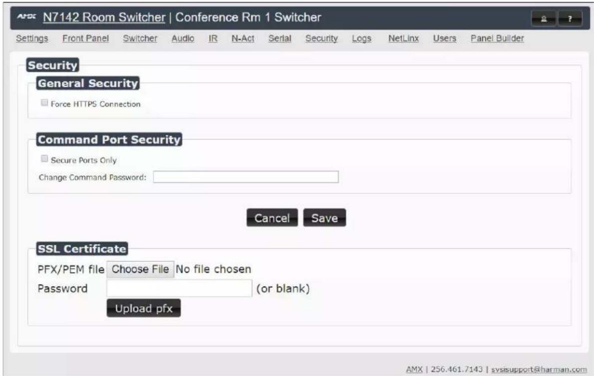
FIG. 38 Security Page
TABLE 24 Security Page Options
| Option Description | |
| General Security | |
| Force HTTPS Connection | Enable to force web page accesses to always be HTTPS. |
| Command Port Security | |
| Secure Ports Only | If enabled, commands must be sent using secure sockets (TLS/SSL) and follow the secure command port protocol. |
| Change Command Password | Set the default password for command encryption. When issuing API commands, this password must precede each command in the format:\r. |
| SSL Certificate | |
| PFX/PEM file | Choose a Personal File Exchange type file to upload. |
| Password If the selected PFX file requires a password, enter the password here. | |
| Upload pfx | Click to upload the chosen custom SSL certificate (pfx file) to the unit. This will replace the current SSL certificate on the unit. |
Logs Page
Click the Logs link at the top of any of the main web pages to access the page shown in Figure 39. The Logs page displays a command log that lists all TCP and UDP messages the unit receives. It also displays the web browser's IP address and gives you options to Refresh and Reset Logs. When in need of assistance from tech support, you can use the Debug Log section to capture useful troubleshooting information. Simply click the Start Debug Log button, wait at least one minute, and click the End Debug Log button to create the file. You can then download and send it to AMX tech support.

FIG. 39 Logs Page
NOTE: For security reasons, only use the Enable Maintenance Mode if instructed by AMX Technical Support. This selection only appears in the secure version of the website (i.e., https).
NetLinx Page
Click the Netlink link at the top of any of the main web pages to access the page shown in Figure 40.
Options are described in Table 25. This page allows you to prepare your N2400 for NetLinx-driven configuration. This is explained in more detail in Appendix B: NetLinx Control on page 59.
NOTE: NetLinx takes over the Serial port when active.

FIG. 40 NetLinx Page
TABLE 25 NetLinx Page Options
| Command Description | |
| Enable Click to enable/disable NetLinx on this device. | |
| Device Status | This status field will show the device to be Online, Connected, Offline, or Unknown. |
| Master Mode | Select Auto, Listen, or URL. |
| IP/URL Enter the address of the Master Controller. | |
| Port | This field should always be set to 1319. |
| Device Number | Defaults to a dynamic device number. May be set to a static range (e.g., 8000). |
| System Number | Determines which system to connect. This setting is dependent upon the Master Mode selected (see above).If Master Mode is set to Auto, the System Number is set and the system discovers the Master Controller's IP address.If Master Mode is set to Listen, the device connects to any Master Controller.If Master Mode is set to URL, the IP of the Master Controller is set. |
| Username Username for the Master Controller. | |
| Password Password for the Master Controller. | |
| Save button Click to save settings made on this page. | |
Users Page
Click the Users link at the top of any of the main web pages to access the page shown in Figure 41. Options are described in Table 26. This page allows you to assign specific privileges to different users.
![N7142 Room Switcher | Conference Rm 1 Switcher Settings Front Panel Switcher Audio IR N-Act Serial Security Logs NetLinx Users Panel Builder Username: admin PW: Add User Users Username Full Admin Auto Redirect Panel Project admin [Switcher Page] Save Delete User AMX | 256.461.7143 | sysisupport@harman.com](/content/2026/06/1248861/images/ae199c938826f0502d7c69bcda34e36707e510054be6ef8b49fc8220be17a78d.jpg)
FIG. 41 Users Page
TABLE 26 Users Page Options
| Command Description | |
| Username To create a new user, enter a new user name in this field. | |
| PW | When creating a new user, enter a password here that will be used upon initial login when that user enters the system. |
| Add User Click to add the user and the associated password to the database. | |
| Username | All users that have been added to this device will display in this column. |
| Full Admin | Enable this box to grant the associated user Full Admin privileges. A user with this privilege level can see all configuration pages and perform all administrator functions.NOTE: If a user without Full Admin privileges selects the Switcher page, then when that user logs in they will see the Switcher page and will not be able to navigate to any other page. |
| Auto Redirect | If this checkbox is enabled, the user will be taken straight to the selected Panel Project page (i.e., the preview panel page) upon login. |
| Panel Project drop-down | This only applies if the Auto Direct checkbox is enabled (see above). Select the Switcher page or a saved Panel Project that the user will auto-directed to at login. All projects created and saved in Panel Builder will be listed here. |
| Save button Click to save changes made to this user profile. | |
| Delete User button Click to delete the associated user from the system. | |
Panel Builder Page
Click the Panel Builder link at the top of any of the main web pages to access the initial page shown in Figure 42. Panel Builder is a GUI application that allows you to create custom panels to be used as a standalone control option or as an extension to a third-party control system. Generate panels for display on any mobile device or PC/Mac. Programming, design, and implementation are incredibly fast using the built in-controls. Refer to Appendix A: Panel Builder on page 50 for details on this feature.
Welcome to the panel builder.
Would you like to create a new, open, or import an existing project?
Recent: [Choose...] ▼
New Open Import
FIG. 42 Launching Panel Builder
Chapter 5: Troubleshooting
This chapter contains possible solutions to some common issues. Should you encounter any problems not covered by these guidelines, please contact SVSI technical support via email (svsisupport@harman.com) or call 256.461.7143 x9900.
| Issues Suggestions | |
| No video displayed on monitor. • Verify proper monitor connection to one of the video outputs.• Verify monitor supports the requested resolution. | |
| Video displays gray or static local play image. | • Verify the video source is connected to an HDMI or analog input.• Verify input is selected to the output using theVIDEO SELECTbuttons on the front of the N7142. |
| Unit is not properly providing PoE. | • Verify that the network cable is plugged Into one of the three left-most ports (labeled POE+) of the 6-port Gbps Switch. |
| Installed card is not operating correctly. | • Verify proper network and video connections.• Refer to the card’sQuick Start Guide(included in card shipment) for more information. |
Appendix A: Panel Builder
Panel Builder allows you to design attractive, intuitive, and easy-to-use touch panel layouts for controlling SVSI's Networked AV Systems and third-party equipment. Panel Builder provides an easy way to design a panel to control any room or facility with just a few simple steps. You can choose to use button and widget libraries that are part of Panel Builder, or import your own images to customize the panel to look exactly as you want.
This following sections explore the Panel Builder user interface, defining each option for easy reference. For more step-by-step project building instructions, refer to the tutorials provided in Panel Builder's Help menu (see Top Ribbon Option Descriptions section on page 52).
NOTE: Panel Builder is accessible through the N7142 Presentation Switcher, N-Touch (as discussed in this document), N-Command (N8001/N8002/N8012 web-based controllers), and also through a stand-alone version that installs directly on your computer.
Beginning a Panel Builder Project
Follow these steps to begin a project in Panel Builder and explore the options provided in the Project Editor.
- From the N7142's GUI, launch Panel Builder. See Figure 43.
![N7142 Room Switcher | Conference Rm 1 Switcher Settings Front Panel Switcher Audio IR N-Act Serial Security Logs NetLinx Users Panel Builder N-Series Serial Database Serial Code: [New] Save Delete Execute ASCII: HEX:](/content/2026/06/1248861/images/8deb48dfd6259324128a3caf03baff6d1fb6c2404f994ffb7fedba25bf3acdfb.jpg)
FIG. 43 Launch Panel Builder
- The Welcome screen appears.
![3. Click the New button. Welcome to the panel builder. Would you like to create a new, open, or import an existing project? Recent: [Choose...] New Open Import 4. Enter a Panel Name, Width, and Height. Add a panel to your project. Enter the details of your new panel: Panel Name: Panel-1 Common Sizes: [Choose...] Panel Width (px): 1024 Panel Height (px): 768 5. Click Add. Add Cancel](/content/2026/06/1248861/images/435ef02dba37175191483227a4f3419d8e8425bd3f91c78da04148b940e428a8.jpg)
FIG. 44 Beginning a New Project in Panel Builder
- The system launches the Project Editor (as shown in Figure 45).
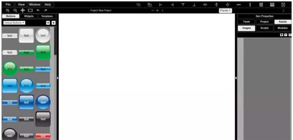
FIG. 45 Project Editor
NOTE: For step-by-step panel building instructions, refer to the Panel Builder Tutorial (available in the Panel Builder Help menu).
Once you arrive at the main Project Editor page, the following screen is displayed. See the sections referenced in the callouts for descriptions of each area of the Project Editor interface.
See the section Top Ribbon Option Descriptions on page 52 for descriptions of the interface's top ribbon of options and icons.
See the section Project Pane Option Descriptions on page 53 for descriptions of this section of the interface.

See the section Tools Pane Option Descriptions on page 57 for descriptions of this section of the interface.
FIG. 46 Project Editor Section References
Top Ribbon Option Descriptions
Refer to Table 27 for detailed descriptions of the options available in the top ribbon of the Project Editor initial page. Hold the Shift key when selecting multiple buttons/widgets (for aligning groups of objects, etc.).
TABLE 27 Top Ribbon Option Descriptions
| Option Description | |
| File | Open new and existing projects, save or delete projects, and perform import/export project functions. |
| View | Preview the current panel in a separate browser window or open the setup script in thePanel Buildereditor to view/edit. |
| Window | SelectTools Paneto display the left pane of the interface (which allows you to add buttons/sliders/etc. to your panel). SelectProject Paneto display the right pane of the interface (which allows you to further edit the panel you are building as well as the overall project, add scripts, etc.). |
| Help | SelectEditorto view a tutorial forPanel Builder,Modulesto view a list of module scripts,Scriptsto view a user guide forPanel Builderscripting, orCommandsto view a list of direct control API commands. |
 | Create a copy of the selected button or widget. This will also clone any scripts/conditionals that are loaded onto the button. |
 | Use to make all buttons the same size. The first button you select (highlighted in green) will be the size that the other selected buttons (highlighted in blue) will conform to when this icon is clicked. Hold theShiftkey to select multiple objects. |
 | Left-align the selected buttons or widgets to the main selected item. The first button you select (highlighted in green) stays in position as the other selected buttons (highlighted in blue) are aligned to it. Hold theShiftkey to select multiple objects. |
 | Right-align the selected buttons or widgets to the main selected item. The first button you select (highlighted in green) stays in position as the other selected buttons (highlighted in blue) are aligned to it. Hold theShiftkey to select multiple objects. |
 | Top-align the selected buttons or widgets to the main selected item. The first button you select (highlighted in green) stays in position as the other selected buttons (highlighted in blue) are aligned to it. Hold theShiftkey to select multiple objects. |
 | Bottom-align the selected buttons or widgets to the main selected item. The first button you select (highlighted in green) stays in position as the other selected buttons (highlighted in blue) are aligned to it. Hold theShiftkey to select multiple objects. |
 | Center-align the selected buttons or widgets horizontally.Hold theShiftkey to select multiple objects. |
 | Center-align the selected buttons or widgets vertically. Hold theShiftkey to select multiple objects. |
 | Center-align the selected buttons or widgets horizontally and vertically. Hold theShiftkey to select multiple objects. |
 | Align and evenly distribute the selected buttons or widgets horizontally. Hold theShiftkey to select multiple objects. |
 | Align and evenly distribute the selected buttons or widgets vertically. Hold theShiftkey to select multiple objects. |
| [2C6G] | Align the selected buttons or widgets to the grid. Allows you to select the number of rows/columns and then aligns the selected objects to that grid. Hold theShiftkey to select multiple objects. |
 | Open the script editor and assign/change scripts for the selected button or widget. |
 | Delete the selected button(s) and/or widget(s). |
 | Zoom in. |
 | Zoom out. |
 | Click/drag to reposition the panel on the screen. |
 | Resize and center the project to fit the current browser window. |
 | Undo previous action. |
 | Redo a previous action that was undone using the undoaction (see above). |
| [+H7GK] | Delete a panel from the current project. |
 | Add a panel to the current project. |
| [08Y7] | Scroll through the panels of the current project. |
Project Pane Option Descriptions
On the right side of the main screen, you will find options that allow you to edit the current panel you are building, your overall project, as well as view your project assets (such as available images, created scripts, and related modules). If you do not see this pane displayed on the main page of the Project Editor, select Window > Project Pane.
This section shows the screens associated with these options as well as tables that contain details regarding each screen.
Item Properties Tab
Refer to Figure 47 and Table 28 for detailed descriptions of the options available on the Item Properties tab. You must have an item (button or widget) selected before clicking this tab in order to view the options.

FIG. 47 Item Properties Tab Pane
TABLE 28 Item Properties Pane Option Descriptions
| Option Description | |
| Basic | View/edit the width, height, and location of the selected item (i.e., the selected button or widget). |
| Layer | Choose what layer the selected item is on. Send the item Up or Down one layer, send to front (Top), or send to back (Bottom). |
| States | Edit/add different states for the selected item (and the associated scripts and appearances during each state). |
| Option Description | |
| Border Set the border width/color/etc. for the selected item. | |
| Box, Drop, and Text Shadow | Add/remove/adjust shadow settings for the selected item. |
| Touch Panel Key Use to assign a touch panel key number (if applicable). | |
| Icon Choose an image to serve as an icon for the selected item. | |
| Text | Edit the text to be displayed on the selected item. |
Panel Tab
Refer to Figure 48 and Table 29 for detailed descriptions of the options available on the Panel tab.
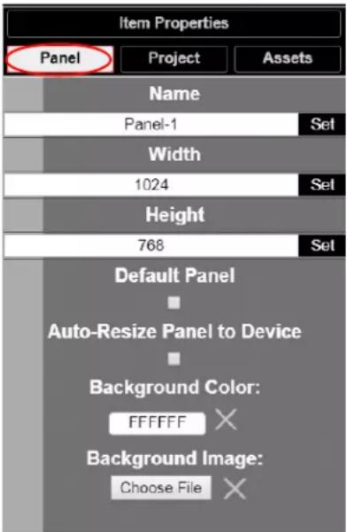
FIG. 48 Panel Tab Pane
TABLE 29 Panel Tab Option Descriptions
| Option Description | |
| Name | View/edit the current panel's name. Click the Set button to accept changes. |
| Width | Set the width of the current panel (in pixels). Click the Set button to accept changes. |
| Height | Set the height of the current panel (in pixels). Click the Set button to accept changes. |
| Default Panel | Enable this checkbox to set the current panel as the device's home screen. |
| Auto-Resize Panel to Device | Enable this checkbox to automatically size the current panel to fit the device's screen when viewed as the active panel. |
| Background Color | Edit the current panel's background color. |
| Background Image | Select an image from your computer to be displayed as the current panel's background. |
Project Tab
Refer to Figure 49 and Table 30 for detailed descriptions of the options available on the Project tab.

FIG. 49 Project Tab Pane
TABLE 30 Project Tab Option Descriptions
| Option Description | |
| Name View/edit the current project's name. | |
| Setup Script View/edit the setup script for the project. | |
| Snap Items to Panel | Enable this checkbox to force all buttons and widgets to remain on the panel background template of the editor (i.e., the white portion of the editor screen). |
| Project Security Code | Enter a pass code (any combination of numbers 1 through 8) if you would like a code to be required to access that panel on the N-Touch Wall Controller. If a code has been entered, a dialog appears on the N-Touch Wall Controller's screen prompting the user to enter the key for access. |
| Project Tree | Lists all items in the project. Click an item in the list to select it on the actual panel. |
Assets Tab
Refer to Figure 50 and Table 31 for detailed descriptions of the options available on the Assets tab.

FIG. 50 Assets Tab Pane
TABLE 31 Assets Tab Option Descriptions
| Option Description | |
| Images View all images in the project. | |
| Scripts | Creates scripts that can be dragged and dropped onto multiple buttons at once. |
| Modules | Use to control a specific type of device with the commands specific to that item. |
Tools Pane Option Descriptions
On the left side of the main screen, you will find options that allow you to access/create buttons, access widgets (such as sliders, text fields, etc.), as well as store panel templates for future use. If you do not see this pane displayed on the main page of the Project Editor, select Window > Tools Pane.
To add a button or widget to your project, simply drag and drop it onto your module display as shown in Figure 51.

FIG. 51 Adding a Button to the Display
This section shows the screens associated with these options as well as tables that contain details regarding each screen.
Buttons Tab
Refer to Figure 52 and Table 32 for detailed descriptions of the options available under the Buttons tab.
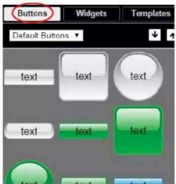
FIG. 52 Buttons Tab Pane
TABLE 32 Buttons Tab Option Descriptions
| Option Description | |
| Default/User Buttons↓↑ | Choose Default Buttons from the drop-down menu to access all of the system buttons. Select User Buttons to access buttons created previously to use as a template. Drag and drop to add a button you created to theUser Buttonlibrary. |
| Click the down arrow to export a selected button to your computer. Click the up arrow to browse to a (previously exported) button file and import it into theUser Buttonlibrary. | |
Widgets Tab
Refer to Figure 53 and Table 33 for detailed descriptions of the options available on the Widgets tab.

FIG. 53 Widget Tab Pane
TABLE 33 Widget Tab Option Descriptions
| Option Description | |
| Sliders | Allows script to fill in value from 0 to 100 (or custom values between two numbers). |
| TextAdds text to | the panel. |
| Image | Adds an image to the panel. Drag and drop this icon to the panel and then double-click it to select an image file (supports .gif, .jpg, or .png file types). |
| Dialer widget Adds | keypad to the panel (for data entry). |
| NVR Control widget | Adds play, stop, pause, etc. buttons for network video recorder (NVR) control. |
Templates Tab
Refer to Figure 54 and Table 34 for detailed descriptions of the options available on the Templates tab.

FIG. 54 Templates Tab Options
TABLE 34 Templates Tab Option Descriptions
| Option Description | |
 | Click the left arrow button to add the current panel to the template page. Click the right arrow button to apply the template to the current panel. |
 | Deletes the currently selected template. |
 | Click the down arrow to export the template library to your computer. Click the up arrow to browse to a (previously exported) file and import it into the template library.NOTE:When buttons are exported, they become .zip files. |
Now that you have familiarized yourself with the interface options, use the tutorials provided in the Help menu of Panel Builder to further explore its capabilities.
Appendix B: NetLinx Control
Introduction
NetLinx Studio is commonly used by system programmers to streamline the integration, programming, organization, and support of their AMX equipment. As the cornerstone of AMX's system design software tools, NetLinx Studio offers programmers the most flexible application capable of generating the most sophisticated code possible. Now equipment in our latest N-Series Networked AV Product comes equipped with NetLinx support. This addendum introduces the new configuration aspects necessary to bring all of your NetLinx-compatible equipment up to speed with the latest functionality. This addendum covers NetLinx functionality as it applies to AMX's N-Series product line and is designed to be used as a supplement to additional product documentation found on our website at http://www.amx.com/techcenter/.
Special Considerations
Netlinx operation requires multicast groups that may conflict with specific video stream numbers. When using Netlinx you must avoid these stream numbers to ensure proper operation:
- Multicast Mode
• Non-interleaved: Avoid streams 31482 and 31483.
• Interleaved: Avoid streams 32125 and 32126.
NetLinx Configuration Using the Unit's Webpage
From any main page of the unit webpage, click the NetLinx tab. See Figure 55. Table 35 provides descriptions for each configuration option.
NOTE: For instructions on how to log in to your unit for the first time, please see the Quick Start Guide (provided in shipment) or visit our website to view the unit's user manual.
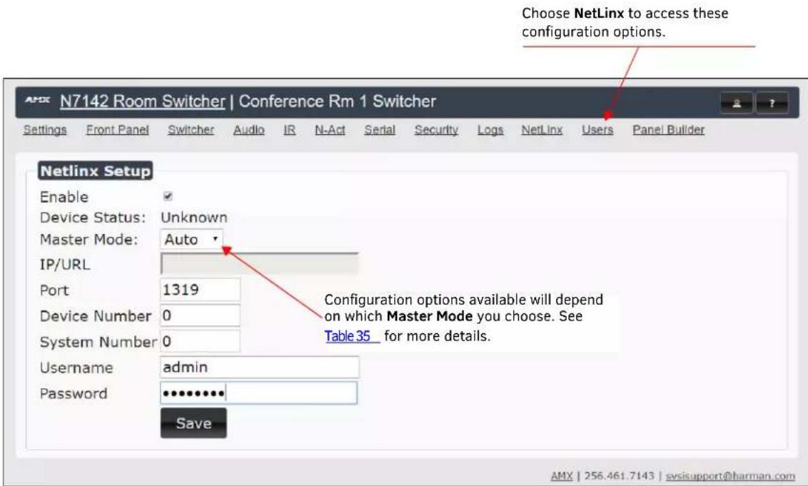
FIGURE 55 NetLinx Configuration Page
TABLE 35 NetLinx Page Options
| Command Description | |
| Enable | Click to enable/disable NetLinx on this device. |
| Device Status | This status field will show the device to be Online, Connected, Offline, or Unknown. |
| Master Mode | Select Auto, Listen, or URL. |
| IP/URL | Enter the address of the Master Controller. |
| Port | This field should always be set to 1319. |
| Device Number | Defaults to a dynamic device number. May be set to a static range (e.g., 8000). |
| System Number | Determines which system to connect. This setting is dependent upon the Master Mode selected (see above).If Master Mode is set to Auto, the System Number is set and the system discovers the Master Controller's IP address.If Master Mode is set to Listen, the device connects to any Master Controller.If Master Mode is set to URL, the IP of the Master Controller is set. |
| Username | Username for the Master Controller. |
| Password | Password for the Master Controller. |
| Save | Save settings made on this page. |
Batch Configurations Using N-Able
One of the many benefits of using N-Able control is batch configuration. This is especially useful in larger deployments. Instead of using the individual unit web pages (discussed in the previous section), simply open N-Able and select Tools > Batch Config. See Figure 56.
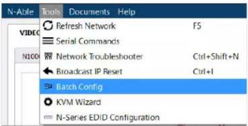
FIGURE 56 Selecting Batch Config in N-Able
The screen shown in Figure 57 displays and allows you to choose the units you would like to enable for NetLinx control. To select multiple units, hold down the
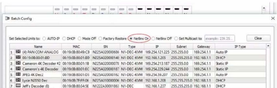
FIGURE 57 Enabling NetLinx on Multiple Units
NOTE: Items are not filtered. In other words, if you send a NetLinx command to a device that does not support it, the command is simply ignored.
Encoder/Decoder Commands
The following section provides information on native, string, IR, and serial commands for N-Series Encoders and Decoders as related to NetLinx management. Commands are issued on the following ports:
- Port 1: Native and String Commands
- Port 2: IRC Command s
- Port 3: Serial Commands
Native Commands Port 1
| Command Description | |
| COSet the current Encoder stream number. | IMPORTANT: This command must be sent to D:P:S port 1 Syntax:SEND_COMMAND, 'CO'Variables:stream = The target stream number from 1 to 32767.NOTE: Stream number MOD 256 must not equal 0 or 255.Examples:SEND_COMMAND 5002:1:0, 'CO 2'Command the Encoder to transmit on stream 2. |
| CISet the current Decoder stream number. | IMPORTANT: This command must be sent to D:P:S port 1 Syntax:SEND_COMMAND, 'CI'Variables:stream = The target stream number from 0 to 32767.NOTE: Stream number MOD 256 must not equal 0 or 255. The only exception to this limitation is that the stream number can be 0 (no stream).Examples:SEND_COMMAND 5002:1:0, 'CI 2'Command the Decoder to receive stream 2. |
| CASet the current Decoder Audio stream number. | IMPORTANT: This command must be sent to D:P:S port 1 Syntax:SEND_COMMAND, 'CA'Variables:stream = The target stream number from 0 to 32767. Set to 0 for the audio stream to follow the video stream.Examples:SEND_COMMAND 5002:1:0, 'CA 2'Command the Decoder to receive audio stream 2. |
| AUDOUT_MUTESet the audio mute. | IMPORTANT: This command must be sent to D:P:S port 1 Syntax:SEND_COMMAND, 'AUDOUT_MUTE-’Variables:ENABLE = Enables audio mute.DISABLE = Disables audio mute.Examples:SEND_COMMAND 5002:1:0, 'AUDOUT_MUTE-ENABLE'Enable audio mute. |
| VIDOUT_MUTESDisable the Encoder/Decoder output stream. | IMPORTANT: This command must be sent to D:P:S port 1 Syntax:SEND_COMMAND, 'VIDOUT_MUTE-’Variables:ENABLE = Enables video mute.DISABLE = Disables video mute.Examples:SEND_COMMAND 5002:1:0, 'VIDOUT_MUTE-ENABLE'Enable video mute. |
| LIVE_PLAYSet the device into live play mode. | IMPORTANT: This command must be sent to D:P:S port 1 Syntax:SEND_COMMAND, 'LIVE_PLAY'Examples:SEND_COMMAND 5002:1:0, 'LIVE_PLAY'Enable live play. |
| LOCAL_PLAYEnable Local Play on Decoders or Host Play on Encoders using the Playlist number. | IMPORTANT: This command must be sent to D:P:S port 1. Syntax:SEND_COMMAND,'LOCAL_PLAY index'Variables:Playlist index = Which Default Playlist index to enable.Examples:SEND_COMMAND 5002:1:0, 'LOCAL_PLAY 1'Enable local play with Default Playlist 1. |
| USB_HID_SERVICEEnable or disable USB. | IMPORTANT: This command must be sent to D:P:S port 1. Syntax:SEND_COMMAND,'USB_HID_SERVICE-’Variables:ENABLE = Enables USB.DISABLE = Disables USB.Examples:SEND_COMMAND 5002:1:0, 'USB_HID_SERVICE-ENABLE'Enable USB. |
| REBOOTReboot the device. | Syntax:SEND_COMMAND,'REBOOT'Variables:NoneExamples:SEND_COMMAND 5002:1:0, 'REBOOT'Reboots the device. |
| ?VIDOUT_OUTPUTRequest the Encoder current stream number. | Syntax:SEND_COMMAND,'?VIDOUT_OUTPUT'Examples:SEND_COMMAND 5002:1:0, '?VIDOUT_OUTPUT'Command Response:'VIDOUT_OUTPUT-852' |
| ?VIDIN_INPUTRequest the Decoder current stream number. | Syntax:SEND_COMMAND,'?VIDIN_INPUT'Examples:SEND_COMMAND 5002:1:0, '?VIDIN_INPUT'Command Response:'VIDIN_INPUT-852' |
| ?AUDIN_INPUTRequest the current audio stream number. | Syntax:SEND_COMMAND,'?AUDIN_INPUT'Examples:SEND_COMMAND 5002:1:0, '?AUDIN_INPUT'Command Response:'AUDIN_INPUT-124' |
| ?AUDOUT_MUTERequest the state of the audio mute. | Syntax:SEND_COMMAND,'?AUDOUT_MUTE'Examples:SEND_COMMAND 5002:1:0, '?AUDOUT_MUTE'Command Response:'AUDOUT_MUTE-ENABLE' |
| ?VIDOUT_MUTERequest the state of the Encoder stream transmission. | Syntax:SEND_COMMAND,'?VIDOUT_MUTE'Examples:SEND_COMMAND 5002:1:0, '?VIDOUT_MUTE'Command Response:'VIDOUT_MUTE-DISABLE' |
| Command Description | |
| ?LIVE_PLAYRequest the status of Live Play. | Syntax:SEND_COMMAND, ' ?LIVE_PLAY'Examples:SEND_COMMAND 5002:1:0, ' ?LIVE_PLAY'Command Response:'LIVE_PLAY-live'or'LIVE_PLAY-local' |
| ?LOCAL_PLAYRequest the Local Play/Host Play Playlist number. | Syntax:SEND_COMMAND, ' ?LOCAL_PLAY'Examples:SEND_COMMAND 5002:1:0, ' ?LOCAL_PLAY'Command Response:'LOCAL_PLAY-1' |
| ?USB_HID_SERVICERequest the status of the USB. | Syntax:SEND_COMMAND, ' ?USB_HID_SERVICE'Examples:SEND_COMMAND 5002:1:0, ' ?USB_HID_SERVICE'Command Response:'USB_HID_SERVICE-<0|1>' |
IR/Serial Send Commands Port 3
| Command Description | |
| GET BAUDGet the RS-232 port's communication parameters. | Syntax:SEND_COMMAND, 'GET BAUD'Example:SEND_COMMAND 5002:3:0, 'GET BAUD'Command Response:'GET-9600,N,8,1' |
| SET BAUDSet the RS-232 port's communication parameters. | Syntax:SEND_COMMAND, 'SET BAUD,,'Variables:baud = baud rates are: 115200, 57600, 38400, 19200, 9600, 4800, 2400, 1200 parity = N (none), O (odd), E (even).data = 8 data bits.stop = 1 and 2 stop bits.Example:SEND_COMMAND 5002:3:0, 'SET BAUD 9600,N,8,1'Command Response:'SET- BAUD 9600,N,8,1' |
Pass Through Commands
For other commands, the NetLinx String command will interpret any existing N-Series API command. For example, to enable the scaler, send the following string command:
SEND_STRING
Similarly, to disable the scaler, send the string command:
SEND_STRING
The response to a pass through string command is the issued command followed by the status message. For example:
- Command string:
SEND_STRING
- Response string
" 'scalerenable-SVSI_RXGEN2:N225A020000140',A,'NAME:00:19:0B:80:01:BD',A,'MAC:00:19:0B:80:01:BD'..."
NOTE: Multiple commands cannot be issued together separated by '\r'.
For more information, refer to the API documentation for the N-Series device.
IR Port 2
Using the NetLinx Studio application, download the appropriate IR file to the N-Series device to use the appropriate channels. Port 2 is used to send IR commands. Some tuning of the NetLinx Pulse Time, IR Command Holdoff, and IR Repeat Holdoff on the N-Series device may be required. The Pulse Time is controlled in the SNAPY code. The IR Command Holdoff and the IR Repeat Holdoff are controlled on the Advanced section of the N-Series device Settings web page. See Figure 58 to see where to find these options.
IR Command Holdoff
• This is the delay between IR commands portions.
- To set the IR Command Holdoff, issue the following string command:
SEND_STRING
IR Repeat Holdoff
- This is the repeat delay between IR commands.
- To set the IR Repeat Holdoff, issue the following string command:
SEND_STRING
, 'setSettings: irc2rtime:
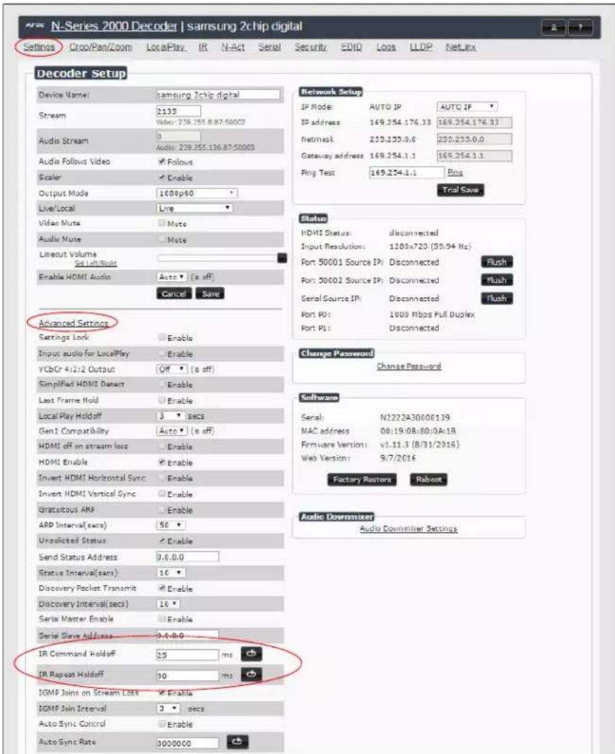
FIGURE 58 Advanced IR Port Settings
Serial Port 3
Port 3 is used for serial commands. Any string sent with the send string command will be output through the serial port. Data returned from the serial port will be from the device also on port 3.
Windowing Processor Commands
The following section provides information on native and string commands for N-Series Windowing Processors as related to NetLinx management. Native and string commands are issued on Port 1.
Native Commands Port 1
| Command Description | |
| COSet the current output stream number. | IMPORTANT:This command must be sent to D:P:S port 1. Syntax:SEND_COMMAND,'CO'Variables:stream = The target stream number from 1 to 32767.Examples:SEND_COMMAND 5002:1:0, 'CO 2'Command the windowing processor to transmit on stream 2. |
| CISet the current stream number for window. | IMPORTANT:This command must be sent to D:P:S port 1. Syntax:SEND_COMMAND,'CI'Variables:window = The target window from 0 to 3.stream = The target stream number from 1 to 32767.Examples:SEND_COMMAND 5002:1:0, 'CI 4 2'Command the windowing processor to receive stream 2 on window 4. |
| CASet the current Decoder Audio stream number. | IMPORTANT:This command must be sent to D:P:S port 1. Syntax:SEND_COMMAND,'CA'Variables:stream = The target stream number from 0 to 32767. Set to 0 for the audio stream to follow the video stream.Examples:SEND_COMMAND 5002:1:0, 'CA 2'Command the Decoder to receive audio stream 2. |
| AUDOUT_MUTESet the audio mute. | IMPORTANT:This command must be sent to D:P:S port 1. Syntax:SEND_COMMAND,'AUDOUT_MUTE-’Variables:ENABLE = Enables audio mute.DISABLE = Disables audio mute.Examples:SEND_COMMAND 5002:1:0, 'AUDOUT_MUTE-ENABLE'Enable audio mute. |
| VIDOUT_MUTESDisable the Encoder output stream.Disable the Decoder video output stream. | IMPORTANT:This command must be sent to D:P:S port 1. Syntax:SEND_COMMAND,'VIDOUT_MUTE-’Variables:ENABLE = Enables video mute.DISABLE = Disables video mute.Examples:SEND_COMMAND 5002:1:0, 'VIDOUT_MUTE-ENABLE'Enable video mute. |
| ?VIDOUT_OUTPUTRequest the current output stream number. | Syntax:SEND_COMMAND,'?VIDOUT_OUTPUT'Examples:SEND_COMMAND 5002:1:0, '?VIDOUT_OUTPUT'Command Response:'VIDOUT_OUTPUT-852' |
| ?VIDIN_INPUTRequest the current stream number. | Syntax:SEND_COMMAND,' ?VIDIN_INPUT'Variables:window = The target window from 0 to 3.Examples:SEND_COMMAND 5002:1:0, ' ?VIDIN_INPUT 3'Command Response:'VIDIN_INPUT-852' |
| ?AUDIN_INPUTRequest the current audio stream number. | Syntax:SEND_COMMAND,' ?AUDIN_INPUT'Examples:SEND_COMMAND 5002:1:0, ' ?AUDIN_INPUT'Command Response:'AUDIN_INPUT-124' |
| ?AUDOUT_MUTERequest the state of the audio mute. | Syntax:SEND_COMMAND,' ?AUDOUT_MUTE'Examples:SEND_COMMAND 5002:1:0, ' ?AUDOUT_MUTE'Command Response:'AUDOUT_MUTE-ENABLE' |
| ?VIDOUT_MUTERequest the state of the Encoder stream transmission. | Syntax:SEND_COMMAND,' ?VIDOUT_MUTE'Examples:SEND_COMMAND 5002:1:0, ' ?VIDOUT_MUTE'Command Response:'VIDOUT_MUTE DISABLE' |
Windowing Processor Pass Through Command Examples
For other commands, the NetLinx String command will interpret any existing N-Series API command. The following sequence of string commands exemplifies the pass through commands used to set up a quad window with white border of two pixels for windows 0 and 1 and no border for windows 2 and 3.
SEND_STRING <DEV>, 'winon:0'
SEND_STRING <DEV>, 'set:0:<stream window 0>'
SEND_STRING <DEV>, 'setbordcol:0:255,255,255'
SEND_STRING <DEV>, 'bordon:0'
SEND_STRING <DEV>, 'setbord:0:2,2'
SEND_STRING <DEV>, 'winset:0:0,0,959,539'
SEND_STRING <DEV>, 'setz:0:1'
SEND_STRING <DEV>, 'winon:1'
SEND_STRING <DEV>, 'set:1:<stream window 1>'
SEND_STRING <DEV>, 'setbordcol:1:255,255,255'
SEND_STRING <DEV>, 'bordon:1'
SEND_STRING <DEV>, 'setbord:1:2,2'
SEND_STRING <DEV>, 'winset:1:960,0,1919,539'
SEND_STRING <DEV>, 'setz:1:2'
SEND_STRING <DEV>, 'winon:2'
SEND_STRING <DEV>, 'set:2:<stream window 2>'
SEND_STRING <DEV>, 'setbordcol:2:255,255,255'
SEND_STRING <DEV>, 'bordoff:2'
SEND_STRING <DEV>, 'winset:2:0,540,959,1079'
SEND_STRING <DEV>, 'setz:2:3'
SEND_STRING <DEV>, 'winon:3'
SEND_STRING <DEV>, 'set:3:<stream window 3>'
SEND_STRING <DEV>, 'setbordcol:3:255,255,255'
SEND_STRING <DEV>, 'bordoff:3'
SEND_STRING <DEV>, 'winset:3:960,540,1919,1079'
SEND_STRING <DEV>, 'setz:3:4'
SEND_STRING <DEV>, 'setbkgd:0'
SEND_STRING <DEV>, 'seta:333'
Network Video Recorder Commands
The following section provides information on native and string commands for the N-Series Network Video Recorder (NVR) as related to NetLinx management.
Native Commands Port 1
| Command Description | |
| MODESet the recording and playback mode. | IMPORTANT:This command must be sent to D:P:S port 1 Syntax:SEND_COMMAND,'MODE'Variables:= the desired recording/playback mode. Modes include:1 = N1000 mode2 = N2000 mode3 = N3000 modeExamples:SEND_COMMAND 5002:1:0, 'MODE 2'Command Response:'MODE-2'Command the NVR to N2000 mode. |
| MPEG_MODESet the conversion mode. | IMPORTANT:This command must be sent to D:P:S port 1 Syntax:SEND_COMMAND,'MPEG_MODE'Variables:= The desired conversion mode.mp4 = Convert to mp4 format.mov = Convert to mov format.Examples:SEND_COMMAND 5002:1:0, 'MPEG_MODE mp4'Command Response:'MPEG_MODE-mp4'Command the NVR to convert to mp4 format. |
| PLAYPlay a recorded stream. | IMPORTANT:This command must be sent to D:P:S port 1 Syntax:SEND_COMMAND,'PLAY,[,[]']'Variables:= Number of the NVR channel to use for playback.= Filename of recording in "f.######.index" format, or zero-based index number in list.= 1 for looping, 0 to play once.= 1 for first stream only (for dual recordings only), 0 to play all streams. (default).= Number of seconds from start to start playing.= Number of seconds from start to end playing.Examples:SEND_COMMAND 5002:1:0, 'PLAY 0,0,1'Command Response:'PLAY-100000000'Indicates NVR is playing on channel 1. |
| PLAY_STOPStop the current playback. | IMPORTANT:This command must be sent to D:P:S port 1 Syntax:SEND_COMMAND,'PLAY_STOP []'Variables:= Number of the NVR channel to use for playback. Use -1 or leave blank for all playing.Examples:SEND_COMMAND 5002:1:0, 'PLAY_STOP'Command Response:'PLAY-000000000'Indicates NVR is not playing on any channel. Stops playback on all channels. |
Native Commands (Cont.)Port 1
| Command Description | |
| PLAY_PAUSEause the current playing video. | IMPORTANT:This command must be sent to D:P:S port 1 Syntax:SEND_COMMAND,'PLAY_PAUSE []'Variables:= Number of the NVR channel to use for pause.Use -1 or leave blank for all playing.Examples:SEND_COMMAND 5002:1:0, 'PLAY_PAUSE'Command Response:nonePause the current playing video. |
| PLAY_RESUMEResume the currently paused, rewinding, or fast forward video. | IMPORTANT:This command must be sent to D:P:S port 1 Syntax:SEND_COMMAND,'PLAY_RESUME []'Variables:= Number of the NVR channel to use for pause.Use -1 or leave blank for all playing.Examples:SEND_COMMAND 5002:1:0, 'PLAY_RESUME'Command Response:noneResume the video. |
| PLAY_FAST_FORWARDPut the current playing video into fast forward using the last speed or the given. | IMPORTANT:This command must be sent to D:P:S port 1 Syntax:SEND_COMMAND,'PLAY_FAST_FORWARD [,[,]]'Variables:= Number of the NVR channel to control. Use -1 or leave blank for all playing.= Number of frames to jump forward per update.Examples:SEND_COMMAND 5002:1:0, 'PLAY_FAST_FORWARD'Command Response:noneStart fast forwarding the playing video. |
| PLAY_REWINDPlay current video backward. | IMPORTANT:This command must be sent to D:P:S port 1 Syntax:SEND_COMMAND,'PLAY_REWIND [,[,]]Variables:= Number of the NVR channel to control. Use -1 or leave blank for all playing.= Number of frames to jump back per update.Examples:SEND_COMMAND 5002:1:0, 'PLAY_REWIND'Command Response:nonePut the current playing video into rewind mode using the last speed. |
| PLAY_SINGLE_STEP_FORWARDSkip a number of frames forward. | IMPORTANT:This command must be sent to D:P:S port 1 Syntax:SEND_COMMAND,'PLAY_SINGLE_STEP_FORWARD [,[,]]'Variables:= Number of the NVR channel to control. Use -1 or leave blank for all playing.= Number of frames to jump forward. Default is 1.Examples:SEND_COMMAND 5002:1:0, 'PLAY_SINGLE_STEP_FORWARD'Command Response:noneStep a single frame forward. |
Native Commands (Cont.)Port 1
| Command Description | |
| PLAY_SINGLE_STEP_BACKWARDSkip a number of frames backward. | IMPORTANT:This command must be sent to D:P:S port 1 Syntax:SEND_COMMAND, 'PLAY_SINGLE_STEP_BACKWARD [,,]]' Variables:= Number of the NVR channel to control. Use -1 or leave blank for all playing.= Number of frames to jump backward. Default is 1.Examples:SEND_COMMAND 5002:1:0, 'PLAY_SINGLE_STEP_BACKWARD'Command Response:noneStep a single frame backward. |
| PLAY_HOLDHold a channel from playing videos until a "release" command is executed. Use "PLAY_STOP" to abort the hold. | IMPORTANT:This command must be sent to D:P:S port 1 Syntax:SEND_COMMAND, 'PLAY_HOLD []' Variables:= Number of the NVR channel to control. Use -1 or leave blank for all playing.Examples:SEND_COMMAND 5002:1:0, 'PLAY_HOLD'Command Response:noneHold all channels from playing video until released. |
| PLAY_RELEASERelease a playback waiting to start. Used for playing multiple channels at the same synchronous time. Hold first, then do the commands for playback, then do the matching release command. | IMPORTANT:This command must be sent to D:P:S port 1 Syntax:SEND_COMMAND, 'PLAY_RELEASE'Examples:SEND_COMMAND 5002:1:0, 'PLAY_RELEASE'Command Response:noneRelease all channels from play hold. |
| RECORDStart a single or dual recording on the given streams. | IMPORTANT:This command must be sent to D:P:S port 1 Syntax:SEND_COMMAND, 'RECORD,,[,,]Variables:= Number of the NVR channel to use for this recording.= Stream number of first video stream to record. = Stream number of first audio stream to record, or 0 to follow vid1stream.= Stream number of second video stream to record.= Stream number of second audio stream to record, or 0 to follow vid2stream.= Length of recording in seconds.= Text of description in ASCII (NO SPACES ARE ALLOWED IN DESCRIPTION).Examples:SEND_COMMAND 5002:1:0, 'RECORD 0,123,0,600,TestRecording'Start a recording on channel 0, video and audio stream 123, for 10 minutes (600 seconds). |
| RECORD_STOPStop the current recording. | IMPORTANT:This command must be sent to D:P:S port 1 Syntax:SEND_COMMAND, 'RECORD_STOP []' Variables:= Number of the NVR channel to control. Use -1 or leave blank for all playing.Examples:SEND_COMMAND 5002:1:0, 'RECORD_STOP'Command Response:noneStop recording video on all channels. |
Native Commands (Cont.)Port 1
| Command Description | |
| RECORD_CONTINUOUSStart a continuous single or dual recording on the given streams. The recording contains the lasttime. | IMPORTANT:This command must be sent to D:P:S port 1 Syntax:SEND_COMMAND,'RECORD_CONTINUOUS,,,,[,,],'Variables:= Number of the NVR channel to use for this recording.= Stream number of first video stream to record.= Stream number of first audio stream to record, or 0 to follow vid1stream.= Stream number of second video stream to record.= Stream number of second audio stream to record, or 0 to follow vid2stream.= Length of recording in seconds.= Text of description in ASCII (NO SPACES ARE ALLOWED IN DESCRIPTION).Examples:SEND_COMMAND 5002:1:0, 'RECORD_CONTINUOUS 0,123,0,600,TestRecording' Command Response:noneStart a continuous recording of the last 10 minutes (600 seconds) on channel 0, video and audio stream 123. |
| RECORD_CONVERTStart a single or dual recording on the given streams and convert the recording to either MP4 or MOV (based on MPEG_MODE) afterward. | IMPORTANT:This command must be sent to D:P:S port 1 Syntax:SEND_COMMAND,'RECORD_CONVERT,,,[,,],'Variables:= Number of the NVR channel to use for this recording.= Stream number of first video stream to record.= Stream number of first audio stream to record, or 0 to follow vid1stream.= Stream number of second video stream to record.= Stream number of second audio stream to record, or 0 to follow vid2stream.= Length of recording in seconds.= bps video output rate, 0=default (7,500,000 bps).= Text of description in ASCII (NO SPACES ARE ALLOWED IN DESCRIPTION).Examples:SEND_COMMAND 5002:1:0, 'RECORD_CONVERT 0,123,0,600,0,TestRecording' Command Response:noneStart a recording on channel 0, video and audio stream 123, for 10 minutes. When the recording is complete, convert the recording at the default 7.5 Mbps video bitrate. |
| RECORD_HOLDHolds a channel from recording videos until a "release" command is executed. Use "stop:" to abort the hold. | IMPORTANT:This command must be sent to D:P:S port 1 Syntax:SEND_COMMAND,'RECORD_HOLD[!'Variables:= Number of the NVR channel to control. Use -1 or leave blank for all playing.Examples:SEND_COMMAND 5002:1:0, 'RECORD_HOLD' Command Response:noneHold all channel from recording video until released. |
Native Commands (Cont.)Port 1
| Command Description | |
| RECORD_RELEASERelease a recording waiting to start. Used for recording multiple channels at the same synchronous time. Hold first, then do the commands for record, then do the matching release command. | IMPORTANT:This command must be sent to D:P:S port 1. Syntax:SEND_COMMAND, 'RECORD_RELEASE'Examples:SEND_COMMAND 5002:1:0, 'RECORD_RELEASE'Command Response:noneRelease all channels from record hold. |
| ?MODEQuery the recording and playback mode. | IMPORTANT:This command must be sent to D:P:S port 1. Syntax:SEND_COMMAND, ' ?MODE'Variables:= The desired recording/playback mode.1 = N1000 mode2 = N2000 mode3 = N3000 modeExamples:SEND_COMMAND 5002:1:0, ' ?MODE'Command Response:'MODE-2'Values:The recording/playback mode (1 = N1000, 2 = N2000, and 3 = N3000). |
| ?MPEG_MODEQuery the conversion mode. | IMPORTANT:This command must be sent to D:P:S port 1. Syntax:SEND_COMMAND, ' ?MPEG_MODE'Examples:SEND_COMMAND 5002:1:0, ' ?MPEG_MODE'Command Response:'MPEG_MODE-mp4'Variables:= The desired conversion mode.mp4 = Convert to mp4 format.mov = Convert to mov format. |
| ?PLAYQuery the playback channels. | IMPORTANT:This command must be sent to D:P:S port 1. Syntax:SEND_COMMAND, ' ?PLAY'Examples:SEND_COMMAND 5002:1:0, ' ?PLAY'Command Response:'PLAY-100000000'Indicating NVR is playing on channel 1. |
| ?PLAY_HOLDQuery the playback channels that are in play hold. | IMPORTANT:This command must be sent to D:P:S port 1. Syntax:SEND_COMMAND, ' ?PLAY_HOLD'Examples:SEND_COMMAND 5002:1:0, ' ?PLAY_HOLD'Command Response:'PLAY_HOLD-100000000'Indicating NVR is holding playing on channel 1. |
| ?RECORDQuery the recording channels. | IMPORTANT:This command must be sent to D:P:S port 1. Syntax:SEND_COMMAND, ' ?RECORD'Examples:SEND_COMMAND 5002:1:0, ' ?RECORD'Command Response:'RECORD-100000000'Indicating NVR is recording on channel 1. |
Native Commands (Cont.)Port 1
| Command Description | |
| ?RECORD_HOLDQuery the recording channels that are in record hold. | IMPORTANT:This command must be sent to D:P:S port 1 Syntax:SEND_COMMAND, ' ?RECORD_HOLD'Examples:SEND_COMMAND 5002:1:0, ' ?RECORD_HOLD'Command Response:'PLAY_HOLD-1000000000'Indicating NVR is holding recording on channel 1. |
Audio over IP Transceiver Commands
The following section provides information on native and string commands for the N-Series Audio over IP Transceiver (ATC) as related to NetLinx management.
Native Commands Port 1
| Command Description | |
| COSet the current output audio stream number. | IMPORTANT:This command must be sent to D:P:S port 1. Syntax:SEND_COMMAND,'CO'Variables:= the target stream number from 1 to 32767Examples:SEND_COMMAND 5002:1:0, 'CO 2'Command the ATC to transmit audio on stream 2. |
| CASet the current input audio stream number. | IMPORTANT:This command must be sent to D:P:S port 1. Syntax:SEND_COMMAND,'CA'Variables:= The target stream number from 1 to 32767.Examples:SEND_COMMAND 5002:1:0, 'CA 2'Command the ATC to receive audio stream 2. |
| AUDOUT_MUTESet the audio mute. | IMPORTANT:This command must be sent to D:P:S port 1. Syntax:SEND_COMMAND,'AUDOUT_MUTE-''Variables:ENABLE = Enables audio mute.DISABLE = Disables audio mute.Examples:SEND_COMMAND 5002:1:0, 'AUDOUT_MUTE-ENABLE'Enables audio mute. |
| REBOOTReboot the device. | Syntax:SEND_COMMAND,'REBOOT'Variables:NoneExamples:SEND_COMMAND 5002:1:0, 'REBOOT'Reboots the device. |
| ?AUDOUT_OUTPUTRequest the current output audio stream number. | Syntax:SEND_COMMAND,'?AUDOUT_OUTPUT'Examples:SEND_COMMAND 5002:1:0, '?AUDOUT_OUTPUT'Command Response:'AUDIN_OUTPUT-123' |
| ?AUDIN_INPUTRequest the current input audio stream number. | Syntax:SEND_COMMAND,'?AUDIN_INPUT'Examples:SEND_COMMAND 5002:1:0, '?AUDIN_INPUT'Command Response:'AUDIN_INPUT-124' |
Native Commands (Cont.)Port 1
| Command Description | |
| ?AUDOUT_MUTERequest the state of the audio mute. | Syntax:SEND_COMMAND, ' ?AUDOUT_MUTE'Examples:SEND_COMMAND 5002:1:0, ' ?AUDOUT_MUTE'Command Response:' AUDOUT_MUTE-ENABLE' |
Pass Through Commands Port 1
For other commands, the NetLinx String command will interpret any existing N-Series API command. For example, to set the ATC's master volume level for the right channel to 50, send the following string command:
SEND_STRING 5002:1:0, 'mastervolright:50'
For more information, refer to the API documentation for the N4321.
N-Command
Pass Through Commands Port 1
The NetLinx String command will interpret any existing N-Series N-Command (N8000/N8001/N8012) API command. For example, to switch the output stream to 30 of a Decoder at IP address 169.254.22.30, send the following string command:
SEND_STRING 5002:1:0, 'switch 169.254.22.30 25'
For more information, refer to the API documentation of N-Command.
Presentation Switcher
Pass Through Commands Port 1
The NetLinx String command will interpret any existing N7142 Presentation Switcher API command. For example, to set the output resolution for VIDEO OUTPUT 1 to 4K60, send the following string command:
SEND_STRING 5002:1:0, 'modeset:1,4K60'
For more information, refer to the API documentation of the N7142.
Appendix C: Minimum Network Requirements
As you look into an N-Series solution and try to decide what type of network topology and infrastructure will be best suited for your application, there are some minimum network requirements that must be considered when choosing the hardware to deploy a Networked AV system. The requirements presented in this guide cover the necessary protocols and features needed to drive an N-Series stream.
NOTE: Specific configuration recommendations given in this document are based off of the Cisco Catalyst series switch. These recommendations could vary from manufacturer to manufacturer.
-
Managed Network Switch
-
Gigabit Ethernet (N1000/N2000 Based Systems)
-
Internet Group Management Protocol (IGMP) Version 2
a. IGMP Snooping
i. Snooping must be enabled on all switches that are communicating with the querier.
b. IGMP Snooping Querying
i. Network must include at least one IGMP Querier to maintain stream connections.
- It is recommended to have all capable switches with the querier enabled and allow IGMP auto-elect to determine the Designated Querier (DQ). a. DQ is determined by the lowest IP addressed switch, but can be manually assigned. However, this would need to be manually configured on all switches to bypass the auto-elect.
ii. Query interval - 30s
- Interval between sending IGMP general queries.
iii. Query Response Interval - 10s
- The maximum time the system waits for a response to general queries.
iv. Last Member Query Interval - 100ms
- The interval to wait for a response to a group specific or group-and-source-specific query message.
v. Immediate Leave (required for N1000, N2x51 4K, N2300 4K, N2400, and N2x35 [Extreme Quality] Low Latency Models)
-
Used to immediately break up multi-cast groups when a leave message is received.
-
Immediate Leave will break any daisy chaining of multiple units together with a single home run and as such you will not be able to have both Immediate Leave and daisy chaining in the same VLAN.
-
Some manufacturers do not have Immediate Leave as an option and use Fast Leave instead.
a. Fast Leave does not guarantee an immediate leave from the multi-cast group and can affect switching speeds and performance.
vi. Optional Protocols
- IGMP Robustness - Default 2
a. Robustness can be adjusted generally from 2-10. The higher the value, the more leave latency is added. b. This protocol is effectively inactive when Immediate Leave is enabled.
c. Warnings/Notices
i. There is a known behavior within IGMP V2 that Encoder streams, whether requested across an uplink or not, will be requested by the DQ and will be present on the uplinks of all switches between the stream source switch and the DQ.
-
Essentially this means that even though you may not be routing a stream to another switch, the DQ's request will still put the stream on the uplink. Therefore, ensure that you have accounted for all streams forwarding to the DQ.
-
A good rule of thumb, when planning for bandwidth considerations on uplinks, is to not exceed 80% of the uplink's total bandwidth capacity to give plenty of overhead for spikes and additional traffic.
-
Multicast routing capabilities on each switch (configured for PIM-SM and with an established rendezvous point) can be designed to limit or mitigate this behavior.
ii. When a multicast host leaves a group, it sends an IGMP leave message. When the leave message is received by the switch, it checks to see if this host is the last to leave the group by sending out an IGMP group-specific or group-and-source specific query message, and starting a timer. If no reports are received before the timer expires, the group record is deleted and a report is sent to the upstream multicast router/querier switch. Lower interval times will increase bandwidth utilization slightly as querying will happen more often.
- Protocol Independent Multicast (PIM)
a. Used to route multicast between VLANs
b. PIM Sparse Mode (PIM-SM)
i. Recommended for use with N-Series multicast products.
ii. PIM-SM uses a pull model to deliver multicast traffic. Only network segments with active receivers that have explicitly requested the data will receive the traffic.
iii. Requires configuration of a Rendezvous Point (RP).
-
Must be configured by administrator.
-
Similar to the DQ in IGMP.
-
All multicast sources must register with the RP to be able to be routed throughout the network.
c. Other PIM modes – not recommended for N-Series
i. Dense Mode (PIM-DM)
ii. Bidirectional (bidir-PIM)
- Jumbo Frames Enabled (For N2300 Series)
a. The N2300 Series Encoders and Decoders produce a frame payload larger than 1500 bytes. This requires the switch to have the capacity of handling jumbo frames enabled.
- Quality of Service (QOS): Managing the delay, delay variation (jitter), bandwidth, and packet loss parameters on a network becomes the secret to a successful end-to-end business solution.
a. Not required for use with N-Series devices
b. Policing
i. A policer typically drops traffic.
ii. Differentiated Services Code Point (DSCP) values can be configured in N-Series devices if QOS is required on the network.
c. Shaping
i. A shaper typically delays excess traffic using a buffer, or queueing mechanism, to hold packets and shape the flow when the data rate of the source is higher than expected.
ii. Cannot be used with N2300 series.
- TCN Flood Off
a. TCN (Topology Change Notification) flooding will cause unnecessary backplane and bandwidth usage when adding or removing a device on the network, which can cause stream interruptions as the flooding sweeps through the network.
i. Note that this command has to be assigned individually per port that is assigned to that VLAN. However it is not necessary with ports on the same switch that will not be set up on the same VLAN as the N-Series devices.
b. Command Example: NO IP IGMP SNOOPING TCN FLOOD

- IMPORTANT SAFETY INSTRUCTIONS
- COPYRIGHT NOTICE
- LIABILITY NOTICE
- AMX WARRANTY AND RETURN POLICY
- ESD WARNING
- FCC AND CANADA EMC COMPLIANCE INFORMATION:
- EU COMPLIANCE INFORMATION:
- WEEE NOTICE:
- Table of Contents
- Chapter 1: Introducing Your New N7142 Room Switcher 6
- Chapter 2: Installing the N7142 9
- Chapter 3: Room Switcher Configuration Options 14
- Chapter 4: Room Switcher Detailed Configuration Options....23
- Chapter 5: Troubleshooting 49
- Appendix A: Panel Builder 50
- Appendix B: NetLinx Control 59
- Chapter 1: Introducing Your New N7142 Room Switcher
- Product Overview
- Common Applications
- Features include:
- Hardware Overview
- Chapter 2: Installing the N7142
- Physical Installation
- Initial Setup
- Internal Switch Configuration
- To enable IGMP Query for the internal switch, follow these steps:
- Advanced Configuration
- Chapter 3: Room Switcher Configuration Options
- Quick Setup Page
- User Presets Page
- Input Page
- Output Page
- Networking Page
- Audio Page
- Advanced Page
- Device Info Page
- Chapter 4: Room Switcher Detailed Configuration Options
- Settings Page
- Room Switcher Setup Section
- Network Setup Section
- Status Section
- Status
- Change Password Section
- LDAP Section
- Software Section
- Software
- Front Panel Page
- AHG N7142 Room Switcher | Conference Rm 1 Switcher
- Room Switcher
- Switcher Page
- 1
- Inputs Tab
- Mixing Tab
- EQ & Outputs Tab
- Advanced Tab
- IR Page
- N-Act Page
- Serial Page
- Security Page
- Logs Page
- NetLinx Page
- Users Page
- Panel Builder Page
- Welcome to the panel builder.
- Chapter 5: Troubleshooting
- Appendix A: Panel Builder
- Beginning a Panel Builder Project
- Top Ribbon Option Descriptions
- Project Pane Option Descriptions
- Item Properties Tab
- Panel Tab
- Project Tab
- Assets Tab
- Tools Pane Option Descriptions
- Buttons Tab
- Widgets Tab
- Templates Tab
- Appendix B: NetLinx Control
- Introduction
- Special Considerations
- NetLinx Configuration Using the Unit's Webpage
- Batch Configurations Using N-Able
- Encoder/Decoder Commands
- Pass Through Commands
- IR Port 2
- IR Command Holdoff
- IR Repeat Holdoff
- Serial Port 3
- Windowing Processor Commands
- Windowing Processor Pass Through Command Examples
- Network Video Recorder Commands
- Audio over IP Transceiver Commands
- Pass Through Commands Port 1
- N-Command
- Presentation Switcher
- Appendix C: Minimum Network Requirements
Brand : AMX
Model : NMX-PRS-N7142
Category : Unspecified