
UC-P8-T-I - Simulator Crestron - Free user manual and instructions
Find the device manual for free UC-P8-T-I Crestron in PDF.


| Product Type | Touch Screen Simulator for Unified Communications |
| Brand | Crestron |
| Model | UC-P8-T-I |
| Display Size | 8 inches |
| Display Type | Capacitive Touch Screen |
| Resolution | 1280 x 800 pixels |
| Dimensions (W x H x D) | 8.9 x 5.9 x 1.5 inches (226 x 150 x 38 mm) |
| Weight | 2.2 lbs (1.0 kg) |
| Power Supply | Power over Ethernet (PoE) IEEE 802.3af |
| Power Consumption | 13 W (max) |
| Ethernet | 10/100/1000 Mbps, PoE |
| USB Ports | 1 x USB 2.0 |
| Mounting | Tabletop stand included; VESA mount optional |
| Operating Temperature | 32°F to 104°F (0°C to 40°C) |
| Humidity | 10% to 90% (non-condensing) |
| Primary Functions | Video conference control, room scheduling, digital signage |
| Supported Platforms | Zoom, Microsoft Teams, Cisco Webex (via Crestron Flex) |
| Cleaning Instructions | Wipe with a soft, dry cloth; do not use liquids or abrasives |
| Security Features | Kensington lock slot |
| Spare Parts & Repairability | No user-serviceable parts; contact Crestron support |
| General Information | Designed for easy integration with Crestron UC UC-ENGINE and other UC systems |
Frequently Asked Questions - UC-P8-T-I Crestron
User questions about UC-P8-T-I Crestron
0 question about this device. Answer the ones you know or ask your own.
Ask a new question about this device
Download the instructions for your Simulator in PDF format for free! Find your manual UC-P8-T-I - Crestron and take your electronic device back in hand. On this page are published all the documents necessary for the use of your device. UC-P8-T-I by Crestron.
USER MANUAL UC-P8-T-I Crestron
Crestron Electronics, Inc.
The original language version of this document is U.S. English. All other languages are a translation of the original document.
Crestron product development software is licensed to Crestron dealers and Crestron Service Providers (CSPs) under limited nonexclusive, nontransferable Software Development Tools License Agreement. Crestron product operating system software is licensed to Crestron dealers, CSPs, and end-users under a separate End-User License Agreement. Both of these Agreements can be found on the Crestron website at www.crestron.com/legal/software_license_agreement.
The product warranty can be found at www.crestron.com/warranty.
The specific patents that cover Crestron products are listed online at www.crestron.com/legal/patents.
Certain Crestron products contain open source software. For specific information, please visit www.crestron.com/opensource.
Crestron, the Crestron logo, and XiO Cloud are either trademarks or registered trademarks of Crestron Electronics, in the United States and/or other countries. Bluetooth is either a trademark or registered trademark of Bluetooth Inc. in the United States and/or other countries. Active Directory and Microsoft Teams are either trademarks or registered trademarks of Microsoft Corporation in the United States and/or other countries. Wi-Fi is either a trade or registered trademark of Wi-Fi Alliance in the United States and/or other countries. Other trademarks, registered trademarks, and trade names may be used in this document to refer to either the entities claiming the marks or their products. Crestron disclaims any proprietary interest in the marks and names of others. Crestron is not responsible for errors in typography or photography.
©2022 Crestron Electronics, Inc.
Revision History
Rev Date Notes Author(s)
A July 29, 2022 Initial version IH
Please send comments and change recommendations to:
SecurityDocs@crestron.com
Contents
Overview ...1
Ports and Protocols...3
Prerequisites ...5
Operating Environment...5
Firmware Version 5
Device Access...5
Default Configuration Settings...5
Microsoft Teams Secure Deployment...6
Required Configuration...7
Create an Admin Account Password...7.
Configure the Network...8.
Wired Network Configuration 8
Wi-Fi Network Configuration...10
802.1X Authentication ..11
Set the Time and Date...14
Configure the Remote Syslog 15
Optional Configuration
Add Users and Groups...17
Configure Bluetooth Communications 17
Configure Automatic Updates 17
Configure a Connection to XiO Cloud 18
Management Functions
Firmware Update 20
User and Group Management...20
Add a User...21
Delete a User 22
Add a Group 22
Delete a Group 23
Overview
This document describes the steps needed to harden a Crestron® installation with Crestron Phones and assumes a basic understanding of security functions and protocols. This guide provides information about the system configuration used for Crestron Flex Phones firmware release 1.0.4.22 or later.
NOTE: The term "device" is used in this document to refer to all applicable Crestron Flex Phone models unless specified otherwise.
The information in this guide pertains to the following device models:
| Model Description | |
| UC-P8-T Crestron Flex 8 in. Audio Desk Phone for Microsoft Teams® Software | |
| UC-P8-T-I Crestron Flex 8 in. Audio Desk Phone for Microsoft Teams® Software, International | |
| UC-P8-T-HS Crestron Flex 8 in. Audio Desk Phone with Handset for Microsoft Teams® Software | |
| UC-P8-T-HS-I Crestron Flex 8 in. Audio Desk Phone with Handset for Microsoft Teams® Software, International | |
| UC-P8-T-C Crestron Flex 8 in. Video Desk Phone for Microsoft Teams® Software | |
| UC-P8-T-C-I Crestron Flex 8 in. Video Desk Phone for Microsoft Teams® Software, International | |
| UC-P8-T-C-HS Crestron Flex 8 in. Video Desk Phone with Handset for Microsoft Teams® Software | |
| UC-P8-T-C-HS-I Crestron Flex 8 in. Video Desk Phone with Handset for Microsoft Teams® Software, International | |
| UC-P10-T Crestron Flex 10 in. Audio Desk Phone for Microsoft Teams® Software | |
| UC-P10-T-I Crestron Flex 10 in. Audio Desk Phone for Microsoft Teams® Software, International | |
| UC-P10-T-HS Crestron Flex 10 in. Audio Desk Phone with Handset for Microsoft Teams® Software | |
| UC-P10-T-HS-I Crestron Flex 10 in. Audio Desk Phone with Handset for Microsoft Teams® Software, International | |
| UC-P10-T-C Crestron Flex 10 in. Video Desk Phone for Microsoft Teams® Software | |
| UC-P10-T-C-I Crestron Flex 10 in. Video Desk Phone for Microsoft Teams® Software, International |
Model Description
| UC-P10-T-C-HS Crestron Flex 10 in. Video Desk Phone with Handset for Microsoft Teams® Software |
| UC-P10-T-C-HS-I Crestron Flex 10 in. Video Desk Phone with Handset for Microsoft Teams® Software, International |
Ports and Protocols
The following ports and protocols may be used by the device depending on the system de and configuration.
Crestron Control Devices
| Function | Destination | Port | From (Sender) | To (Listener) | Notes | ||
| Crestron-CIP | 41794/TCP | Device | Control | System | Crestron | Internet Protocol | |
| Crestron-SCIP | 41796/TCP | Device | Control | System | Secure | Crestron Internet Protocol | |
| HTTPS | 49200/TCP | Remote | Device | Device | Web | API for User | Crestron Interfaces HTML5 |
Common Ports
| Function | Destination | Port From | (Sender) To | (Listener) | Notes | |
| NTP | 123/UDP | Device | NTP Server | Network Time Protocol (NTP) | ||
| SSH | 22/TCP | Admin Workstation | Device | Used for configuration and console. | ||
| LDAP | 389/TCP | Device | Admin Server | |||
| LDAPS | 636/TCP | Device | Admin Server | |||
| HTTPS | 443/TCP | Admin or End User Workstation | Device | Secure web configuration | ||
| HTTPS | 443/TCP | Device | XiO Cloud® Service | For XiO Cloud services only and not required for device functionality. A persistent connection is made via AMQP over WebSockets. HTTPS services such as routing lookups and file transfers may be used. | ||
| Function | Destination | Port | From (Sender) | To (Listener) | Notes | |
| HTTPS | 443/TCP | Device | Microsoft | Portal | For Microsoft portal services only and not required for device functionality. HTTPS services such as routing lookups and file transfer may be used. | |
| HTTPS | 443/TCP | Device | Firmware | Server | Firmware upgrade path | |
| HTTPS | 443/TCP | Device | APK Server | APK upgrade path | ||
| DHCP | 67/UDP | Device | DHCP | Server DHCP addressing | ||
| DHCP | 68/UDP | DHCP | Server | Device | DHCP addressing | |
| HTTP | 80/TCP | End User Workstation | Device | Web configuration | ||
| WPAD | 80/TCP | Device WPAD File Server | Gets the PAC file from the server. | |||
| Remote Syslog | Configurable | Device Remote Syslog Server | Uses TLS | |||
| HTTP Proxy | Configurable | Device Proxy Server | ||||
| HTTPS Proxy | Configurable | Device Proxy Server | ||||
| Kerberos | 88/TCP | Device | KDC (Key Distribution Center) | |||
| DNS | 3/TCP/UDP | Device DNS server |
Prerequisites
In order to perform a secure configuration, the following prerequisites must be met.
Operating Environment
Crestron assumes the following about the operating environment of its systems:
- The system is not capable of Multi-Factor Authentication (MFA). If your organization's policy requires MFA, you cannot use the system.
- Physical security is commensurate with the value of the system and the data it contains and is assumed to be provided by the environment.
- Administrators are trusted to follow and provide all administrator guidance.
Firmware Version
Crestron Flex Phones must be running firmware version 1.0.4.22 or later.
Device Access
The administrator can access and configure the device by using a web browser. Additionally, some aspects of configuration can be performed via the XiO Cloud® service. This document describes device configuration using the web browser.
The device also provides local setup pages for commonly used configuration settings. The local setup pages can be accessed from the touch screen display by tapping the gear icon on page and then selecting Device Settings.
Default Configuration Settings
In order to configure the device, it must first be placed in its factory default state. A d be returned to this state as follows:
- Disconnect the Ethernet cable from the LAN port that supplies the device power over (Power over Ethernet).
- Reconnect the Ethernet cable to the LAN port. The device starts to boot.
-
When the LED light bar below the touch screen display starts to flash green, press an hold the Volume Up and Microphone Mute buttons simultaneously for at least 10 seconds. A page is displayed asking whether a factory restore should be performed.
-
Use the Volume Up or Volume Down buttons to select Yes, and then press the Microphone Mute button to confirm the selection.
- Wait 5 to 10 minutes for the self-recovery process to complete.
- Proceed with the network configuration.
Microsoft Teams Secure Deployment
The device runs the Microsoft Teams® software app. For more information on how to secu deploy Microsoft Teams across an enterprise, refer to docs.microsoft.com/en-us/MicrosoftTeams/security-compliance-overview.
Required Configuration
The following sections describe the configuration changes required for the device for a secure deployment.
Create an Admin Account Password
The first time the web configuration interface is accessed, a Welcome page is displayed prompting the user to log in with admin credentials.
Welcome Page

- Enter the default admin account username (admin) and password (admin) in the appropriate text fields.
- Select Login. A Change Password page is displayed prompting the user to change the admin account password.
Change Password Page

-
Enter and confirm a new password that meets the validation rules shown (8-32 characters, contains at least 1 number, 1 uppercase letter, 1 lowercase letter, and 1 sj character).
-
Select Save to return to the Welcome page.
-
Enter the admin account username and new password created in step 3.
-
Select Login. Upon successful login, the web configuration user interface is displayed.
Configure the Network
The following sections provide information about the tasks necessary to configure the network
Wired Network Configuration
To configure the device to communicate on the LAN over Ethernet, the following changes are made. If DHCP is available on the local network, then no additional configuration change necessary. If DHCP is not available or if the administrator wishes to manually set the net configuration, then the IP address, subnet mask, default gateway, and DNS server settings be set.
To configure the wired network settings for the device:
- Select the Settings tab.
-
Expand the System Setup accordion.
-
Click the + (plus) icon next to Network to display time and date settings for the device.
Settings - Network (Wired Network Settings)

- Enter the following information for the wired network configuration.
• Network Configuration
Primary Static DNS: Enter a primary DNS server address to use for DNS name lookups.
Secondary Static DNS: Enter a secondary DNS server address to use for DNS name lookups.
- Primary LAN
- DHCP: Turn off the toggle to turn off DHCP. Turning off DHCP allows the wired network to be configured manually.
IP Address: If DHCP is turned off, enter the desired device IP address on the network.
- Subnet Mask: If DHCP is turned off, enter the desired device subnet mask address on the network.
Default Gateway: If DHCP is turned off, enter the desired gateway router address on the network.
-
Configure any other wired network settings as needed (such as VLAN, PC Port Mode, CDP, LLDP, and so forth) for your deployment.
-
Select Save Changes from the Action menu.
Wi-Fi Network Configuration
To configure the device to communicate to the LAN over Wi-Fi™ communications, the followir changes must be made. If DHCP is available on the local network, then no additional configuration changes are necessary. If DHCP is not available or if the administrator wishes manually set the network configuration, then the domain, IP address, subnet mask, default gateway, and DNS server settings must be set.
To configure the Wi-Fi network settings for the device:
-
Select the Settings tab.
-
Expand the System Setup accordion.
-
Click the + (plus) icon next to Network to display time and date settings for the device.
Settings - Network (Wi-Fi Network Settings)

-
Turn on the Wi-Fi toggle to turn on the Wi-Fi adapter.
-
Enter the following information for the Wi-Fi network configuration.
-
DHCP: Turn off the toggle to turn off DHCP. Turning off DHCP allows the Wi-Fi network to be configured manually.
- Domain: If DHCP is turned off, enter the fully qualified Wi-Fi domain name on the network.
- IP Address: If DHCP is turned off, enter the desired device IP address on the network.
- Subnet Mask: If DHCP is turned off, enter the desired device subnet mask address on the network.
- Default Gateway: If DHCP is turned off, enter the desired gateway router address on the network.
- Primary DNS Server: Enter a primary DNS server address to use for DNS name lookups.
-
Secondary DNS Server: Enter a secondary DNS server address to use for DNS name lookups.
-
Select Save Changes from the Action menu.
802.1X Authentication
802.1X is an IEEE network standard designed to enhance the security of both wireless and Ethernet networks. This device supports 802.1X on its primary wired Ethernet interface only. the network requires 802.1X, the device must be configured for 802.1X before being put on network.
Configure 802.1X Settings
To configure 802.1X settings for the device:
- Select the 802.1x Configuration tab to display settings for configuring 802.1X authentication.
802.1x Configuration
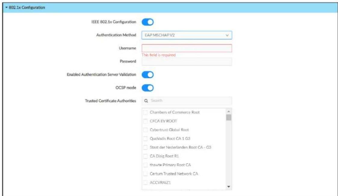
- Turn on the IEEE 802.1x Configuration toggle to turn on 802.1X authentication.
-
Select the desired 802.1X authentication method from the Authentication Method drop-down menu:
-
Select EAP-TLS Certificate to authenticate using a client certificate.
-
Select EAP MSCHAP V2 to authenticate using a username and password.
-
If EAP MSCHAP V2 is selected for Authentication Method, enter the username and password required for the client authentication.
- Turn on the Enabled Authentication Server Validation toggle to turn on server validatic turned on, the 802.1X supplicant will validate the authentication server's certificate.
- If Enabled Authentication Server Validation is turned on and if your server supports C (Online Certificate Status Protocol), turn on the OCSP mode toggle to require a valid OCSP stapling response for all not-trusted certificates in the server certificate chain.
- Select trusted CAs (Certificate Authorities) from the Trusted Certificate Authorities selections to be used for server validation.
NOTE: For more information on configuring trusted certificate authorities, refer to Configure Trusted Certificate Authorities on page 13.
- Select the check box to the left of a CA to select it as a trusted CA.
-
Enter a search term into the text field at the top of the CA menu to search display CAs that match the search term.
-
Select Save Changes from the Action menu.
Configure Trusted Certificate Authorities
Trusted Certificate Authorities (CAs) can be added or deleted from the device for use with 802.1X and remote Syslog server validation.
To configure Trusted Certificate Authorities on the device:
- Select Manage Certificates from the Actions menu.
Actions Menu

The Manage Certificates dialog box is displayed.
Manage Certificates Dialog Box

- To add a new certificate:
a. Select the tabs at the top of the dialog box to select the desired CA type that added (Root, Intermediate, Machine, or Web Server). The same settings are provided for each CA type.
b. Select Add [CA Type] Certificate, where [CA Type] is the selected CA type.
c. Navigate to the CA file on the host computer.
d. Select the CA file, and then select Open. A success message is displayed if the upload is successful, and the certificate will be added to the table for its respe CA type.
- To delete a certificate, select the trash can button to the right of the certificate's row, and then select OK when prompted to confirm the deletion.
Set the Time and Date
All devices use NTP to synchronize their clock. By default, the device is configured to receive data from pool.ntp.org. A custom NTP server can be used instead.
NOTE: The device does not support using secure NTP servers at this time.
To customize the time and date settings on the device:
-
Select the Settings tab.
-
Expand the System Setup accordion.
-
Click the + (plus) icon next to Time/Date to display time and date settings for the device.
Settings - Remote Syslog

- Enter the following information for the time and date configuration:
- Custom Time Server: Enter the IP address or Fully Qualified Domain Name (EQDN) of the custom NTP server.
- Date Format: Use the drop-down menu to select the format that the date will display on the device.
- Time Format: Select the time format that the time will display on the device (12 or 24 hour).
- Time Zone: Use the drop-down menu to select the correct time zone for the dev 5. Select Save Changes from the Action menu.
Configure the Remote Syslog
Devices do not send audit logs to a remote Syslog server by default. A connection to a r Syslog server must be turned on and configured manually.
To turn on sending audit logs to a remote Syslog server:
NOTE: The remote server host must have a system log server with applicable security certificates and sufficient disk space to store the active system log. The host must also configured to archive older system logs and to offload them over time. If TLS is turned TLS-enabled server with the appropriate certificates is required.
-
Select the Settings tab.
-
Expand the Remote Syslog accordion to display settings for the remote Syslog. Settings - Remote Syslog

-
Turn on the Syslog toggle.
-
Enter the following information for the remote Syslog configuration:
- Remote Server Address: Enter the IP address or Fully Qualified Domain Name (FQDN) of the remote Syslog server.
- Remote Server Port: Enter the web port of the remote Syslog server.
- Log Level: Select one of the following log levels to determine which messages are logged to the remote Syslog. All messages of that log level or above will be log
NOTE: For examples of common events that can trigger messages for specific logging levels, refer to the UC-P8 and UC-P10 Series Desk Phones Product Manual.
- DEBUG: Logs all "debug" messages and above to the Syslog.
- INFO: Logs all "info" messages and above to the Syslog.
- WARNING: Logs all "warning" messages and above to the Syslog.
- ERROR: Logs all "error" messages and above to the Syslog.
- Syslog Keyword Filter: (Optional) Enter keywords to filter the Syslog entries by those keywords. Multiple keywords should be entered as a comma-delimited list without any spaces (for example, "SIP,registration,codec").
- Trusted Certificate Authorities: If TLS is turned on, select trusted CAs (Certificate Authorities) from the provided CAs to be used for server validation.
NOTE: For more information on configuring trusted certificate authorities, refer to Configure Trusted Certificate Authorities on page 13.
- Select the check box to the left of a CA to select it as a trusted CA.
-
Enter a search term into the text field at the top of the CA menu to send and display CAs that match the search term.
-
Select Save Changes from the Action menu.
Optional Configuration
The following sections provide information about optional device configuration settings.
Add Users and Groups
It is likely that additional users will need to be given access to the device. Refer to User and Group Management on page 20 for instructions.
Configure Bluetooth Communications
Bluetooth™ communications are turned on by default to allow connections to supported peripheral devices. If your environment or policies do not permit Bluetooth communications, the setting can be turned off.
To turn off Bluetooth communications:
- Select the Settings tab.
- Expand the Connections accordion to display settings for the Bluetooth connection. Settings - Connections

- Turn off the Bluetooth toggle.
- Select Save Changes from the Action menu
Configure Automatic Updates
The device is configured to perform automatic updates by default. When automatic updates turned on, the device will connect to the provided update server and check for updates w scheduled (either at a set day and time or polling interval). If the device detects that an to the firmware or Microsoft Teams APK is available, the update will be downloaded and installed automatically. If your environment or policies do not permit automatic updates, this setting can be turned off.
To turn off automatic updates:
-
Select the Settings tab.
-
Expand the Auto Update accordion to display settings for automatic updates. Settings - Auto Update

-
Turn off the Auto Update Firmware toggle.
-
Turn off the Auto Update APK toggle.
-
Select Save Changes from the Action menu.
Configure a Connection to XiO Cloud
The device is connected to the XiO Cloud® service by default, which allows the device to be discovered by and claimed into the XiO Cloud service. If your environment or policies do not permit communications with external services, this settings can be turned off.
To turn off a connection to XiO Cloud:
-
Select the Settings tab.
-
Expand the XiO Cloud accordion to display settings for the XiO Cloud connection. Settings - XiO Cloud

- Turn off the XiO Cloud Connection toggle.
- Select Save Changes from the Action menu.
Management Functions
The following sections provide information about device management functions.
Firmware Update
To perform a manual firmware update:
- Select Upload Firmware from the Actions menu.
Actions Menu

- Navigate to the firmware BIN file on the host computer.
- Select the firmware BIN file, and then select Open. If the firmware BIN file is upload successfully, a message window is displayed with the status of the firmware update.
- Upon successful firmware update, a dialog box is displayed indicating that the update successful. Select OK, then log back into the web configuration interface.
User and Group Management
Users and groups can be added to the device after an administrator account has been created. User and group management is handled through the Active Directory (LDAP) service. All users and groups must be created in Active Directory before they can be added to the device.
NOTE: The device does not support any local access levels outside of the local admin account. User and group access levels are created and managed through Active Directory.
The following sections describe how to manage users and groups on the device.
Add a User
To add an Active Directory user to the device:
-
Select the Security tab.
-
Expand the Access Control accordion.
-
Select the Users tab to display settings for configuring users on the device. Security - Access Control (Users Tab)

- Select Create User. The Create User dialog box is displayed. Create User Dialog Box

-
Enter the user name in the Name text field. The user name must match exactly the name in Active Directory.
-
Select Yes to create the new user. The user is added to the Users table on the Security page.
Delete a User
To delete an Active Directory user from the device:
NOTE: The local admin user cannot be deleted from the device.
-
Select the Security tab.
-
Expand the Access Control accordion.
-
Select the Users tab to display settings for configuring users on the device. Users Tab

-
Select the trash can button to the right of the user's table row. A dialog box is displayed confirming the deletion.
-
Select Yes to delete the user.
The user is removed from the device but not from the Active Directory service.
Add a Group
To add an Active Directory group to the device:
-
Select the Security tab.
-
Expand the Access Control accordion.
-
Select the Groups tab to display settings for configuring groups on the device.
Security - Access Control (Groups Tab)

- Select Create Group. The Create Group dialog box is displayed. Create Group Dialog Box

-
Enter the domain and group name in the Name text field. The domain and group must match exactly the domain and group in Active Directory (such as "CRESTRON.COM\Idapusers").
-
Select Yes to create the new group. The user is added to the Groups table on the Security page.
All users of the Active Directory group inherit the access level set for the group within A Directory.
Delete a Group
To delete an Active Directory group from the device:
-
Select the Security tab.
-
Expand the Access Control accordion.
-
Select the Groups tab to display settings for configuring groups on the device.
Groups Tab

- Select the trash can button to the right of the group's table row. A dialog box is displayed confirming the deletion.
- Select Yes to delete the group.
The group is removed from the device but not from the Active Directory service.
- Revision History
- Contents
- Overview ...1
- Ports and Protocols...3
- Prerequisites ...5
- Required Configuration...7
- Optional Configuration
- Management Functions
- Overview
- Ports and Protocols
- Prerequisites
- Operating Environment
- Firmware Version
- Device Access
- Default Configuration Settings
- Microsoft Teams Secure Deployment
- Required Configuration
- Create an Admin Account Password
- Configure the Network
- Wired Network Configuration
- Wi-Fi Network Configuration
- 802.1X Authentication
- Configure 802.1X Settings
- Configure Trusted Certificate Authorities
- Set the Time and Date
- Configure the Remote Syslog
- Add Users and Groups
- Configure Bluetooth Communications
- Configure Automatic Updates
- Configure a Connection to XiO Cloud
- Firmware Update
- User and Group Management
- Add a User
- Delete a User
- Add a Group
- Delete a Group
Brand : Crestron
Model : UC-P8-T-I
Category : Simulator