
TW2-33B2-C25 - Heating KING - Free user manual and instructions
Find the device manual for free TW2-33B2-C25 KING in PDF.


| Product Type | Fan Heater |
| Dimensions (HxWxD) | 250 x 200 x 150 mm |
| Weight | 1.5 kg |
| Power Supply | 220-240 V, 50 Hz |
| Power Consumption | 2000 W |
| Heating Settings | 2 levels (low/high) |
| Fan Only Mode | Yes |
| Thermostat | Adjustable |
| Safety Features | Overheat protection, tip-over switch, cool-touch housing |
| Maintenance | Clean with a dry cloth; do not immerse in water |
| Spare Parts Availability | Contact manufacturer or authorized dealers |
| Warranty | 2 years |
Frequently Asked Questions - TW2-33B2-C25 KING
User questions about TW2-33B2-C25 KING
0 question about this device. Answer the ones you know or ask your own.
Ask a new question about this device
Download the instructions for your Heating in PDF format for free! Find your manual TW2-33B2-C25 - KING and take your electronic device back in hand. On this page are published all the documents necessary for the use of your device. TW2-33B2-C25 by KING.
USER MANUAL TW2-33B2-C25 KING
Overhead Short Wave Electric Infrared Heater
1, 2, and 3 Lamp Units

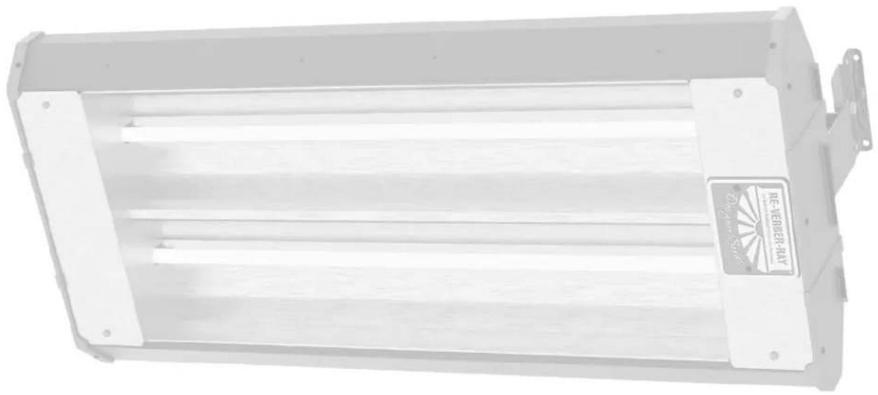
natural_image
Exterior view of a white rectangular electronic device with horizontal slats and mounting brackets (no visible text or symbols)WARNING

All persons involved with the installation, operation, and maintenance of the heater system must read and understand all the information in this manual.
Improper installation, adjustment, alteration, service, or maintenance can cause property damage, injury, or death. Read and understand the installation, operating, and maintenance instructions thoroughly before installing or servicing this equipment.
INSTALLER: Present this manual to the end user.
Keep these instructions in a clean and dry place for future reference.
Model#: ____ Serial #: ____
(located on rating label)
LIOSW2-Rev. 24418
Print: XM-06/19 (XXX)
Contents
1.0 Safety 3
Safety Symbols 3
Applications 3
Model Number Designation Chart 4
AvailableModels and Operational Specifications 4
Clearances to Combustibles 5
Safety Labels and Their Locations 7
Standard, certifications, and Government Regulations 8
2.0 Installation 9
Design 10
Heater Mounting 11
Lamp Installation 13
Outdoor Application 14
Electrical Wiring 14
3.0 Maintenance 16
Troubleshooting guide 17
Heater Assembly Components 18
Parts List 19
! WARNING
California Proposition 65
This product can expose you to chemicals including lead and carbon monoxide, which are known to the State of California to cause birth defects or other reproductive harm.
For more information, go to www.P65Warnings.ca.gov.
1.0 Safety
WARNING

Improper installation, adjustment, alteration, service, or maintenance can cause property damage, serious injury, or death. Read and understand the installation, operating, and maintenance instructions thoroughly before installing or servicing this equipment. Only trained, qualified personnel with proper electrical experience may install or service this equipment.
Safety Symbols
Safety is the most important consideration during installation, operation, and maintenance of the infrared heater. You will see the following symbols and signal words when there is a hazard related to safety or property damage.

WARNING
Warning indicates a potentially hazardous situation which, if not avoided, could result in death or injury.

CAUTION
Caution indicates a potentially hazardous situation which, if not avoided, could result in minor or moderate injury.
NOTICE
Notice indicates a potentially hazardous situation which, if not avoided, could result in property damage.
Applications
Commercial / Industrial (Indoors & Outdoors)
Infrared heaters are designed and certified for use in industrial and commercial buildings such as warehouses, manufacturing plants, aircraft hangars, and vehicle maintenance shops. For maximum safety, the building must be evaluated for potential hazards before installing the heater system. A critical safety factor to consider before installation is the clearances to combustibles.
Outdoor Residential Only
This heater is NOT approved for use in an indoor residential application. This includes, but is not limited to, attached garages, living quarters, solariums, etcetera. Consult the local fire marshal and/or insurance provider if unsure of your application.
WARNING
Not For Residential Use.
Installation of this infrared heater system in residential indoor spaces, RVs, mobile homes, etc. may result in property damage, fire, serious injury, or death.
Chart 1.1 • Model Number Designation Chart
| Series | Material Type | Lamp Qty. | Voltage Code | Lamp Wattage Code | Lamp Type (Color) |
| RH-24 | B = Black Powder Coat or S = Stainless Steel | 1 | A = 120 VAC | 16 = 1,600 | R= Ruby Lamp or W= Standard Lamp |
| B = 208 VAC | |||||
| C = 240 VAC | 25 = 2,500 | ||||
| RH-33 | 2 | D = 277 VAC | 32 = 3,200 | ||
| RH-46 | G = 480 VAC | 36 = 3,650 | |||
| 3 | H = 575 VAC | 38 = 3,800 |
Model Configuration Examples: SW2-24B1-C16R or SW2-33S2-G25W
Chart 1.2 • Available Models and Operational Specifications
| Series Lamp Qty. Voltage; Phase Amperes Watts BTU/h | |||||
| RH-24 | 1 | 120; 1 ph 13.33 | 1,600 5,459 | ||
| 208; 1 ph 7.69 | |||||
| 240; 1 ph 6.67 | |||||
| 277; 1 ph 5.77 | |||||
| 480; 1 ph 3.33 | |||||
| 2 | 208; 1 ph 15.38 | 3,200 10,919 | |||
| 240; 1 ph 13.33 | |||||
| 277; 1 ph 11.54 | |||||
| 480; 1 ph 6.67 | |||||
| 3 | 208; 1 or 3 ph 23.08 | 4,800 16,378 | |||
| 240; 1 or 3ph 20.00 | |||||
| 277; 1 or 3 ph 17.31 | |||||
| 480; 1 or 3ph 10.00 | |||||
| RH-33 | 1 | 208; 1 ph 12.02 | 2,500 8,530 | ||
| 240; 1 ph 10.42 | |||||
| 277; 1 ph 9.02 | |||||
| 480; 1 ph 5.21 | |||||
| 2 | 208; 1 ph 24.04 | 5,000 17,065 | |||
| 240; 1 ph 20.83 | |||||
| 277; 1 ph 18.04 | |||||
| 480; 1 ph 10.42 | |||||
| 3 | 277; 1 or 3 ph 27.06 | 7,500 25,590 | |||
| 480; 1 or 3 ph 15.625 | |||||
| RH-46 | 1 | 277; 1 ph 11.55 | 3,200 10,919 | ||
| 480; 1 ph 7.60 | 3,650 12,454 | ||||
| 575; 1 ph 6.60 | 3,800 12,978 | ||||
| 2 | 277; 1 ph 23.10 | 6,400 21,838 | |||
| 480; 1 ph 15.21 | 7,300 24,909 | ||||
| 575; 1 ph 13.22 | 7,600 25,955 | ||||
| 3 | 480; 1 or 3 ph 22.81 | 10,950 | 37,636 | ||
| 575; 1 or 3 ph 19.83 | 11,400 | 38,933 | |||
Clearances to Combustibles
WARNING


Placement of explosive objects, flammable objects, liquids, and vapors close to the heater may result in explosion, fire, property damage, serious injury, or death. Do not store or use explosive objects, liquids, or vapors in the vicinity of the heater.
Failure to comply with the published clearances to combustibles could result in personal injury, death, and/or property damage.
The outside surfaces of the heater are hot during operation and after operation. If contact is made, permanent skin damage may occur. Do not move, handle, or service the unit during operation or while hot.
CAUTION

Signs shall be posted specifying the maximum permissible stacking height in order to maintain clearances to combustibles.
Hazards Include:
For maximum safety the building must be evaluated for hazards before installing the heater system. Examples include, but are not limited to:
• Gas and electrical lines
- Combustible and explosive materials
• Chemical storage areas
- Areas of high chemical fume concentrations
- Provisions for accessibility to the heater
- Adequate clearances around air openings
• Vehicle parking areas
• Vehicles with lifts or cranes
- Storage areas with stacked materials
- Lights
- Sprinkler heads
• Overhead doors and tracks
- Dirty, contaminated environment
A critical safety factor to consider before installation is the clearances to combustibles. Clearance to combustibles is defined as the minimum distance you must have between the indicated surface and the combustible item. Considerations must also be made for moving objects around the infrared heater. The following is a partial list of items to maintain clearances from:
Combustible Items Include: Moving Objects Include:
- Wood • Overhead doors
- Paper • Vehicles on lifts
- Fabric • Cranes
- Chemicals • Hoists
- Wall or roof insulation • Car wash equipment
- Plastics
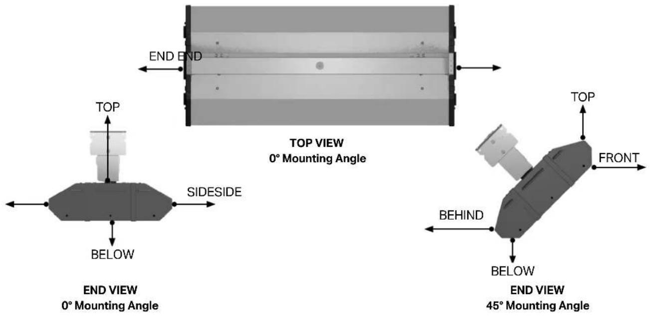
When installing the infrared heater system, the minimum clearances to combustibles must be maintained. These distances are shown in Chart 1.3 and on the heater. If you are unsure of the potential hazards, consult your local fire marshal, fire insurance carrier, or other qualified authorities on the installation of infrared heaters for approval of the proposed installation.
Chart 1.3 • Clearances to Combustibles in Inches (Millimeters) - see Figure 1.1
| Length | Mounting Angle | Side | End Top | BelowFront Behind | ||
| Single Element | ||||||
| 24" | 0° 16 (40) | 16 (407) 12 | (305) 6 (153) 56 | (1423) | ||
| 33" | ||||||
| 46" | 45° 47 (1) | 194) 4 (102) 12 | (305) 10 (254) | 40 (1016) | ||
| Double Element | ||||||
| 24" | 0° 28 (71) | 2) 28 (712) 26 | (661) 6 (153) 86 | (2185) | ||
| 33" | ||||||
| 46" | 45° 86 (2) | 185) 4 (102) 26 | (661) 10 (254) | 86 (2185) | ||
| Triple Element | ||||||
| 24" | 0° 31 (78) | 8) 31 (788) 34 | (864) 9 (229) 10 | (2667) | ||
| 33" | ||||||
| 46" | 45° 105 (2) | 667) 4 (102) 3 | (864) 10 (254) | 105 (2667) | ||
* Heaters mounted on an angle between 0° and 45° must maintain clearances posted for 0° or 45°, whichever is greater.
NOTE: Ensure that building materials with a low heat tolerance (i.e., awnings, fabrics, plastics, sprinklers, insulation, etc.) are protected against degradation. This may require the heater to be mounted at a distance in excess of the published clearances to combustibles. Contact the material manufacturer for specific details.
Figure 1.1 • Clearances to Combustibles
Safety Labels and Their Locations
It is important to provide warnings to alert individuals to potential hazards and safety actions. Signs should state the hazards for the particular application and be legible to the building occupants. Consult the factory or a factory representative for additional information on signage compliance.
Safety warning labels must be maintained on the infrared heater. Illustrations of the safety labels and their locations are pictured below. When no longer legible, they must be replaced. Contact either your local distributor or the product manufacturer for obtaining replacement signs or labels.

F/N: LL001 - Clearance Safety Tag (Affix adjacent to heater's controller)
Standards, Certifications, and Government Regulations
Installation of this infrared heater must comply with all applicable local, state, and national specifications, regulations, and building codes. Contact the local building inspector and/or fire marshal for guidance.
The heater must be electrically grounded in accordance with the following codes:
United States: Refer to National Electrical Code ^6 , ANSI/NFPA 70 (latest edition). Wiring must conform to the latest edition of National Electrical Code ^6 , local ordinances, and any special diagrams from the manufacturer.
Canada: Refer to Canadian Electrical Code CSA C22.1 Part 1 (latest edition).
King Products units comply with or are certified by one or more of the
following organizations or standards:
• CSA 22.2 #46 - M1988
• UL 2021
2.0 Installation
WARNING

Read and understand the installation, operating, and maintenance instructions thoroughly before installing or servicing this equipment.
Design
To ensure a safe, properly designed heating system, a layout should be developed for the correct placement of the infrared heater(s).
Aside from safety factors such as clearances to combustibles (see Chart 1.3 on page 6), consideration should also be given to factors such as the environment (e.g., cold/drafty, average, protected), heat coverage (sq. ft.) needed, heater centers, the distance behind a person or work station(s), etcetera. Also, the effective infrared surface temperature of a person or object may be diminished with wind above 5 mph. Wind barrier(s) may be required. Most importantly, clearances to combustibles must always be maintained! Refer to hazards on page 5.
When positioning the heaters, keep in mind combustible materials, lights, sprinkler heads, overhead doors, storage area with stacked materials, gas and electrical lines, parked vehicles, cranes, etcetera. Refer to Page 6 for minimum clearances to verify that a safe installation exists.
This installation manual, along with national, state, provincial, and local codes, address these issues. It is critical that you read, understand, and follow all guidelines and instructions. Always inspect and evaluate the mounting conditions, application, and wiring.
When heated, materials high in hydrocarbons (solvents, paint thinner, mineral spirits, formaldehydes, etc.) can evaporate and/or degrade. This may result in odors or fumes being emitted into the environment. To correct this problem, clean the area and/or introduce additional ventilation. Heaters installed and serviced in accordance with the installation manual do not emit foul odors into the environment.
IMPORTANT: Fire sprinkler heads must be located at an appropriate distance from the heater to avoid an inadvertent discharge. This distance may exceed the published clearances to combustibles. Certain applications may require the use of high temperature sprinkler heads or relocation of the heaters.
CAUTION
Fire sprinkler systems containing propylene glycol, antifreeze, or other potentially flammable substances shall not be used in conjunction with this heater without careful consideration for and avoidance of inadvertent discharge hazards. For further information consult applicable NFPA codes. Always observe applicable state and local codes.
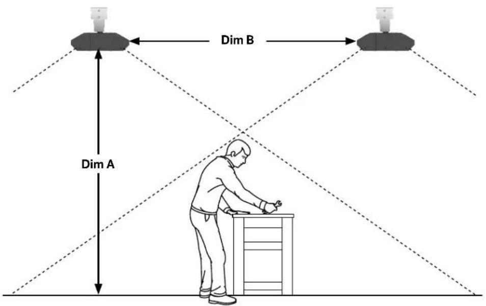
Chart 2.1 • SW2 Series Basic Heating Application Chart
| Series | Lamp Qty. | Recommended Mounting Height (Ft.)* [Dim. A] | Recommended Distance Between Heaters (Ft.) [Dim. B] | Approximate Square Foot Coverage | Approximate Watts per Square Foot |
| RH-24 | 1 10 | to 12 5 to 10 400 4 | |||
| 2 10 | to 12 6 to 12 400 8 | ||||
| 3 12 | to 14 7 to 14 600 8 | ||||
| RH-33 | 1 10 | to 12 6 to 12 400 6 | |||
| 2 12 | to 14 7 to 14 600 8 | ||||
| 3 12 | to 14 8 to 16 600 12 | ||||
| RH-46 | 1 12 | to 14 7 to 14 600 6 | |||
| 2 14 | to 16 8 to 16 850 8 to 9 | ||||
| 3 14 | to 16 9 to 18 850 12 to 13 |
* Clearances to combustibles published in this manual and on safety labels must be maintained at all times. Factory recommended mounting heights are listed as a guideline. If infrared heaters are mounted too low or too high, they may result in discomfort or lack of heat.
Chart 2.2 • Estimating Required Load
| Type of Building | Watts Req. per SquareFoot at Floor Level |
| Insulated 10 | |
| Uninsulated 16 | |
| Outdoor Sheltered 25 to 30 | |
| Outdoor Unsheltered 30 to 45 |
When comfort heating people, two heaters should be used to heat both sides of the individual. Heater installation shall comply with all IOPM, NEC, ANSI/NFPA-70, CEC, and local restrictions.
Figure 2.1 • Heating Application
Heater Mounting
WARNING

Improper suspension of the infrared heater may result in collapse and being crushed. Always suspend from a permanent part of the building structure that can support the total force and weight of the heater.
Failure to maintain minimum clearance to combustibles may result in fire and/or explosion, property damage, serious injury, or death. Always maintain minimum clearances and post signs or provided tags (F/N: LL001) adjacent to heater's controller. Signs should state the hazards for the particular application and be legible to the building occupants. Consult the factory or a factory representative for additional information on signage compliance.
The heater can be suspended with chains or rigid threaded rod. Local codes, or conditions that would cause the unit to move (e.g., wind drafts, blowers, crane rails, etc.), may require rigid threaded rod. Consult all applicable codes before installation.
The heater must be level from end to end and may be 0^ to 45^ on horizontal. Refer to Figures 2.2 and 2.3.
Figure 2.2 • Heater Dimensions
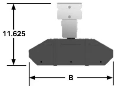
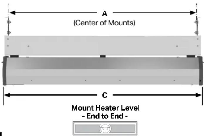
Chart 2.3 • Physical Dimensions (inches)
| Model No. A B C | |||
| RH-24X1 | 23.50 9.625 24.50 | ||
| RH-24X2 | 23.50 15.25 24.50 | ||
| RH-24X3 | 23.50 21.00 24.50 | ||
| RH-33X1 | 32.50 9.625 33.50 | ||
| RH-33X2 | 32.50 15.25 33.50 | ||
| RH-33X3 | 32.50 21.00 33.50 | ||
| RH-46X1 | 45.50 9.625 46.50 | ||
| RH-46X2 | 45.50 15.25 46.50 | ||
| rh-46X3 | 45.50 21.00 46.50 | ||
Figure 2.3 • Mounting Centers

Top Channel Assembly
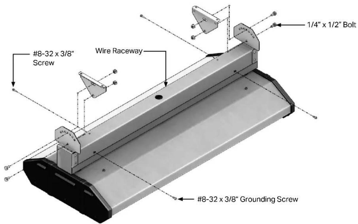
① Attach the mounting brackets to the top wire raceway. On each end, place (1) 1/4" x 1/2" bolt through the bottom hole of the mounting bracket and through the bottom hole of the top wire raceway. Place (1) 1/4" lock nut on each bolt. Do not tighten completely. Refer to Figure 2.4.
NOTE: The mounting brackets are NOT required for chain suspension.
② Adjust wire raceway to desired mounting angle.
③ On each side, place (1) 1/4" x 1/2" bolt through slot in the mounting bracket and the hole in the top wire raceway. Place (1) 1/4" lock nut on each bolt and tighten.
④ Tighten lock nuts from Step 1.
⑤ Hook heater body into mounted wire raceway. Unit will hang freely by the "T" hinge, leaving both hands free to wire unit. Refer to Figure 2.4.
⑥ Run supplied high temperature wires out to field supplied junction box. DO NOT make connections inside the wire raceway.
⑦ Close wire raceway using the (4) #8-32 x 3/8" grounding screws provided in hardware pack.
Figure 2.4 • Top Channel Assembly
Lamp Installation
CAUTION
Disconnect power prior to installing or replacing supplied quartz lamp(s). The elements can and should be installed prior to mounting the heater.
① Ensure appliance is OFF and is cool to the touch.
② Remove both service access panels using a 1/4" nut driver.
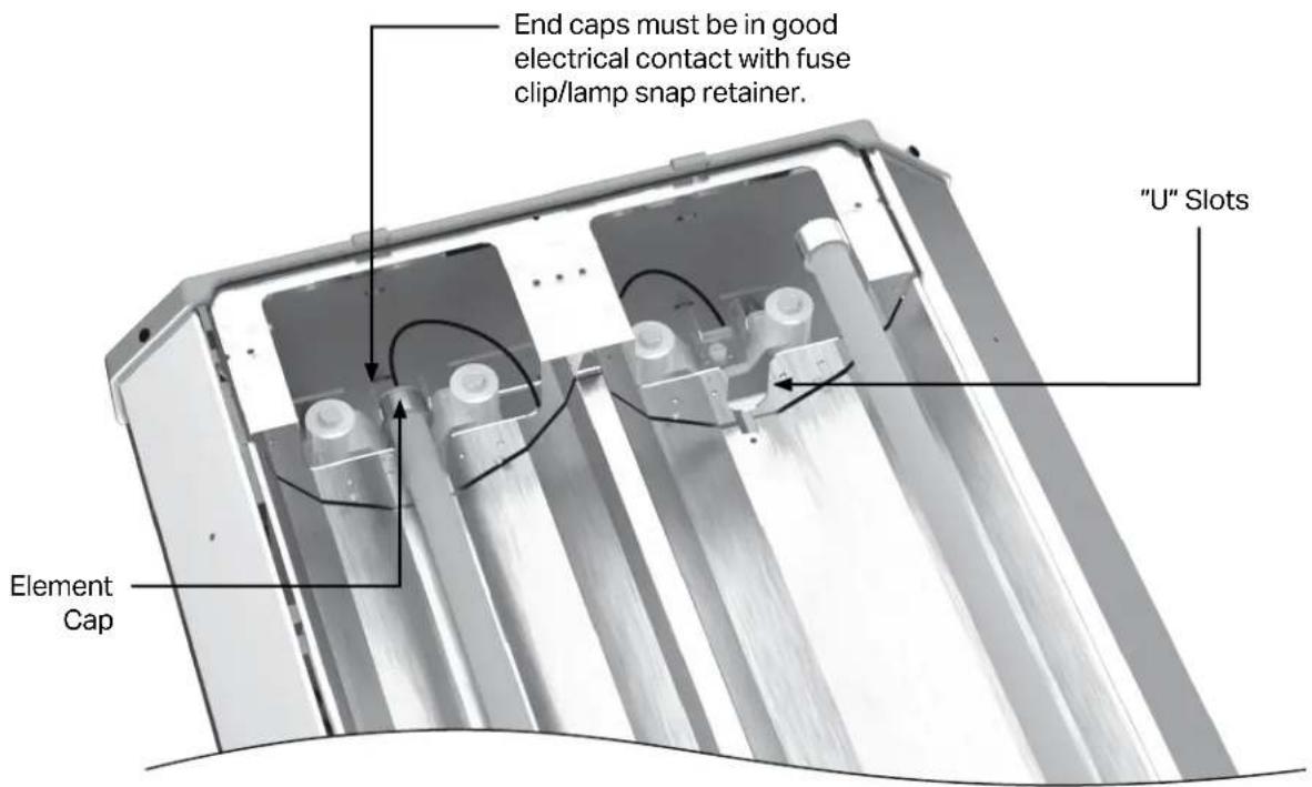
③ Open lamp retains by firmly rotating the retainers on both sides of the unit (see Figure 2.5).
4 Position heating elements in "U" slots and firmly press the connector end into the clip(s), one end at a time. Avoid handling the quartz glass as much as possible.
⑤ Rotate the lamp retainer into closed position.
6 Repeat steps 3 through 5 until all heating elements have been installed.
⑦ After heating elements have been installed, the quartz glass should be wiped off with alcohol using a clean cloth.
⑧ Reinstall the service access panels.
Figure 2.5 • Lamp Installation
NOTE: RH series heaters are designed for use with quartz lamp infrared heating elements only. They are NOT intended to be used with straight metal rod heating elements. Replace lamps with parts from Detroit Radiant Products Company only!
Totally Exposed Outdoor Applications
CAUTION
For totally exposed outdoor applications (not ceiling protected) ensure connections are made as illustrated in Figure 2.6.
Figure 2.6 • Exposed Outdoor Application
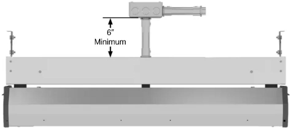
NOTE: All conduit, conduit fittings, and junction boxes are field supplied. Must be NEMA Type 4X or equivalent. Heater must be suspended from mounting brackets.
Electrical
WARNING
Electric Shock
Field wiring to the heater must be connected and grounded in accordance with national, state, provincial, and local codes, and to the guidelines in the this manual. In the United States, refer to the most current revisions to the ANSI/NFPA 70 Standard and in Canada, refer to the most current revisions the CSA C22.1 Part I Standard.
Disconnect power to heater before servicing.
Failure to follow these instructions can result in death or electrical shock.
This fixture is equipped with high temperature silicone lead wires to make connections to branch circuit. Remove the wire-ties prior to making electrical connections.
Wiring connections should always be through one of the knockouts in the top wire raceway. Wire connections must also be made outside of the top of the wire raceway. Consult the factory or a qualified electrician for details on staging.
Supply wires must be a copper conductor type with a minimum size of 10 AWG.
The heater must be connected to the earthing conductor (green wire) installed by the factory.
Reference top of page 14 for use in totally exposed outdoor applications.
Wiring Diagrams
Figure 2.7 • Wiring Diagram for Units with 1 Lamp

Figure 2.8 • Wiring Diagram for Units with 2 Lamps
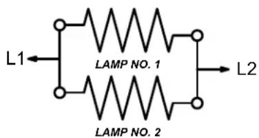
Figure 2.9 • Wiring Diagram for Units with 3 Lamps

Field Wiring
Figure 2.10 • Single Phase Service

flowchart
graph TD
    A["CONTROL DEVICE"] --> B["SINGLE LAMP UNIT"]
    A --> C["DOUBLE LAMP UNIT"]
    A --> D["TRIPLE LAMP UNIT"]
    B --> E["L1"]
    C --> F["L2"]
    D --> G["L1"]
    D --> H["L2"]
Figure 2.11 • Three Phase Service

3.0 Maintenance
It is recommended that the following become a standard yearly procedure to obtain maximum operating efficiency and trouble free operation.
During long periods of non-usage, remove or cover heater with a polyethylene bag and disconnect from power supply. If further service to the heater is desired, contact your representative or the factory.
① Clean reflector surface with a damp cloth.
② Ensure heater is secure on all hanging points.
③ Maintain clearances to combustibles at all times. Immediately remove objects in violations of the published clearances to combustibles.
④ Check electrical wires and connections for wear or any kind of damage.
Maintenance Log
| Date Maintenance Performed Replacement Parts Required | ||
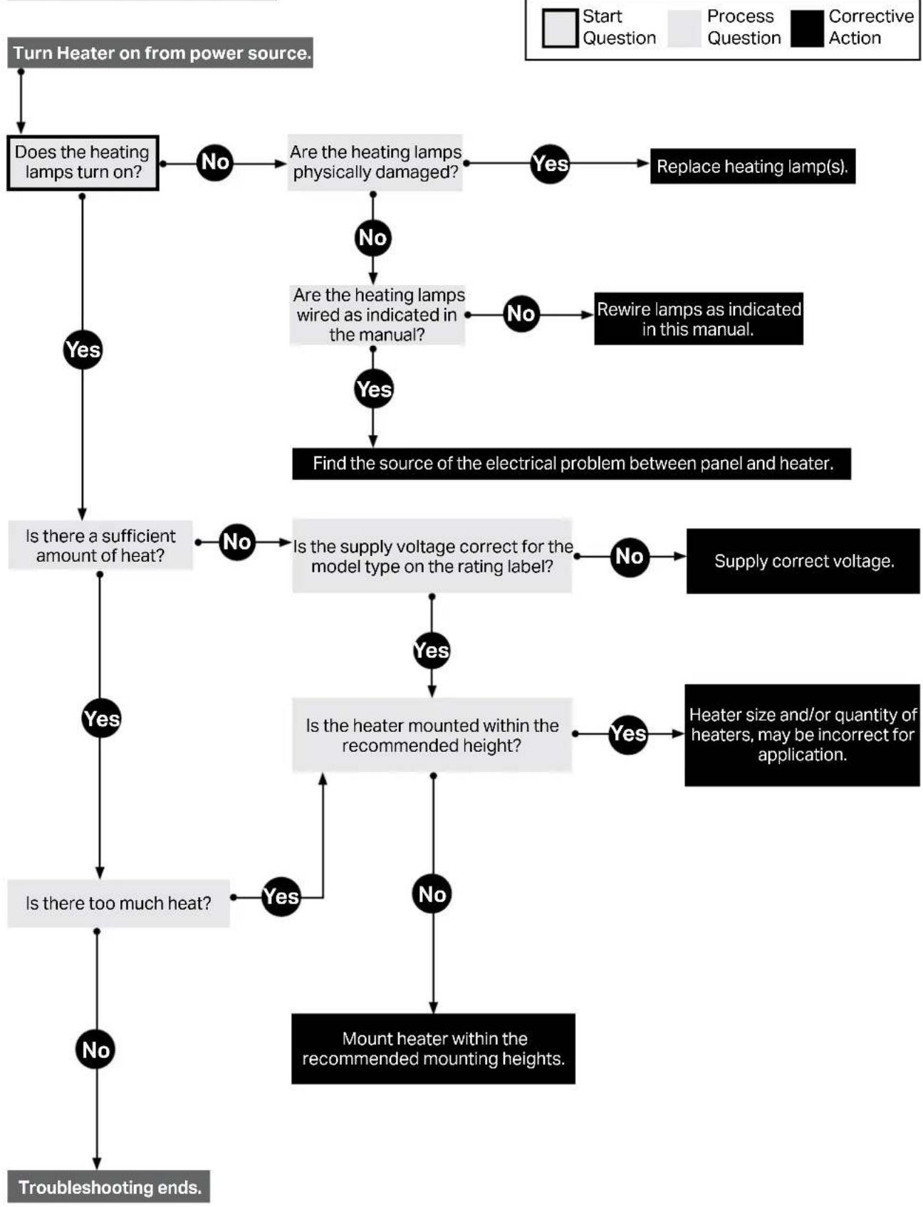
Troubleshooting Guide
flowchart
graph TD
    A["Turn Heater on from power source."] --> B["Does the heating lamps turn on?"]
    B -->|No| C["Are the heating lamps physically damaged?"]
    C -->|Yes| D["Replace heating lamp(s)."]
    B -->|Yes| E["Is there a sufficient amount of heat?"]
    E -->|No| F["Is the supply voltage correct for the model type on the rating label?"]
    F -->|Yes| G["Is the heater mounted within the recommended height?"]
    F -->|No| H["Supply correct voltage."]
    G -->|Yes| I["Heater size and/or quantity of heaters, may be incorrect for application."]
    G -->|No| J["Mount heater within the recommended mounting heights."]
    I --> K["Troubleshooting ends."]
    J --> K
    C --> L["Are the heating lamps wired as indicated in the manual?"]
    L -->|No| M["Rewire lamps as indicated in this manual."]
    L -->|Yes| N["Find the source of the electrical problem between panel and heater."]
    N --> E
    F --> O["Is the heater mounted within the recommended height?"]
    O -->|Yes| P["Heater size and/or quantity of heaters, may be incorrect for application."]
    O -->|No| Q["Mount heater within the recommended mounting heights."]
    P --> R["Troubleshooting ends."]
Heater Assembly Components
Figure 3.1 • Components

Parts List
Chart 3.1 • General Parts List
| Part No. | Description | Part No. | Description |
| EL-0161 | Mounting Brackets | EL-1002 | Single Lamp Service Access Panel |
| EL-033 | 12 Gauge Wire Length for 33" (specify color) | EL-1106 | Single Lamp Reflector, 24" Model |
| EL-034 | 12 Gauge Wire Length for 24" (specify color) | EL-1107 | Single Lamp Reflector, 33" Model |
| EL-035 | 12 Gauge Wire Length for 46" (specify color) | EL-1108 | Single Lamp Reflector, 46" Model |
| EL-039 | Rubber Spacer, LG, End (2 per heater) (not shown) | EL-11521 | Single Lamp Shell Assembly, 24" Model |
| EL-040 | Rubber Spacer, SM, Center (not shown) | EL-11531 | Single Lamp Shell Assembly, 33" Model |
| EL-070A | Lamp; 1600 W, 120 V, 24", Clear | EL-11541 | Single Lamp Shell Assembly, 46" Model |
| EL-071A | Lamp; 1600 W, 208 V, 24", Clear | EL-1160 | Single Lamp Shield |
| EL-072A | Lamp; 2500 W, 208 V, 33", Clear | EL-1161 | Single Lamp Nylon End Panel |
| EL-073A | Lamp; 1600 W, 240 V, 24", Clear | Double Lamp Model Parts List | |
| EL-074A | Lamp; 2500 W, 240 V, 33", Clear | EL-255 | Double Lamp Chassis Assembly |
| EL-075A | Lamp; 1600 W, 480 V, 24", Clear | EL-1003 | Double Lamp Service Access Panel |
| EL-076A | Lamp; 2500 W, 480 V, 33", Clear | EL-1206 | Double Lamp Reflector, 24" Model |
| EL-077A | Lamp; 3650 W, 480 V, 46", Clear | EL-1207 | Double Lamp Reflector, 33" Model |
| EL-078A | Lamp; 3800 W, 575 V, 46", Clear | EL-1208 | Double Lamp Reflector, 46" Model |
| EL-080A | Lamp; 1600 W, 120 V, 24", Ruby | EL-12521 | Double Lamp Shell Assembly, 24" Model |
| EL-081A | Lamp; 1600 W, 208 V, 24", Ruby | EL-12531 | Double Lamp Shell Assembly, 33" Model |
| EL-082A | Lamp; 2500 W, 208 V, 33", Ruby | EL-12541 | Double Lamp Shell Assembly, 46" Model |
| EL-083A | Lamp; 1600 W, 240 V, 24", Ruby | EL-1260 | Double Lamp Shield |
| EL-084A | Lamp; 2500 W, 240 V, 33", Ruby | EL-1261 | Double Lamp Nylon End Panel |
| EL-085A | Lamp; 1600 W, 480 V, 24", Ruby | Triple Lamp Model Parts List | |
| EL-086A | Lamp; 2500 W, 480 V, 33", Ruby | EL-355 | Triple Lamp Chassis Assembly |
| EL-087A | Lamp; 3650 W, 480 V, 46", Ruby | EL-1004 | Triple Lamp Service Access Panel |
| EL-088A | Lamp; 3800 W, 575 V, 46", Ruby | EL-1306 | Triple Lamp Reflector, 24" Model |
| EL-1037 | Wire Bushing | EL-1307 | Triple Lamp Reflector, 33" Model |
| EL-1052 | Busbar Assembly | EL-1308 | Triple Lamp Reflector, 46" Model |
| EL-10571 | Wire Raceway Assembly, 24" Model | EL-13521 | Triple Lamp Shell Assembly, 24" Model |
| EL-10581 | Wire Raceway Assembly, 33" Model | EL-13531 | Triple Lamp Shell Assembly, 33" Model |
| EL-10591 | Wire Raceway Assembly, 46" Model | EL-13541 | Triple Lamp Shell Assembly, 46" Model |
| Single Lamp Model Parts List | EL-1360 | Triple Lamp Shield | |
| EL-155 | Single Lamp Chassis Assembly | EL-1361 | Triple Lamp Nylon End Panel |
^1 p#dnumber as is for black finish or add -SS for stainless steel finish. Ex: EL-016 for black mounting brackets and EL-016-SS for stainless steel mounting brackets.
Visit our online parts reference library at www.reverberray.com/shop for further technical data related to parts.
- WARNING
- Contents
- Safety 3
- Installation 9
- Maintenance 16
- ! WARNING
- California Proposition 65
- Safety
- Safety Symbols
- CAUTION
- NOTICE
- Applications
- Commercial / Industrial (Indoors & Outdoors)
- Outdoor Residential Only
- Not For Residential Use.
- Clearances to Combustibles
- Hazards Include:
- Combustible Items Include: Moving Objects Include:
- Safety Labels and Their Locations
- Standards, Certifications, and Government Regulations
- King Products units comply with or are certified by one or more of the
- Installation
- Design
- Heater Mounting
- Top Channel Assembly
- Lamp Installation
- Totally Exposed Outdoor Applications
- Electrical
- Electric Shock
- Wiring Diagrams
- Field Wiring
- Maintenance
- Heater Assembly Components
- Parts List
Brand : KING
Model : TW2-33B2-C25
Category : Heating