
IPRKPW0215 - Power Strip StarTech.com - Free user manual and instructions
Find the device manual for free IPRKPW0215 StarTech.com in PDF.


| Product Type | 15-Outlet Power Strip with Surge Protection |
| Dimensions (L x W x H) | 12.6 x 2.4 x 1.3 in (32.0 x 6.1 x 3.3 cm) |
| Weight | 1.5 lb (0.68 kg) |
| Power Input | 15A / 125V / 1875W |
| Number of Outlets | 15 (NEMA 5-15R) |
| USB Charging Ports | 2 (USB-A, total 2.1A) |
| Power Cord Length | 6 ft (1.8 m) |
| Surge Protection | 1200 Joules, 3-line protection |
| EMI/RFI Filtering | Yes, up to 80 dB noise reduction |
| On/Off Switch | Illuminated rocker switch with circuit breaker |
| LED Indicators | Power (green), Surge Protection (red/green) |
| Mounting Options | Wall-mountable, keyhole slots |
| Safety Certifications | UL, cUL, FCC |
| Care and Cleaning | Unplug before cleaning; use dry cloth; do not use liquids |
| Spare Parts and Repairability | No user-serviceable parts; replace unit if damaged |
| Warranty | Lifetime warranty with $100K connected equipment guarantee |
| Operating Temperature | 32°F to 104°F (0°C to 40°C) |
| Material | High-impact ABS plastic |
Frequently Asked Questions - IPRKPW0215 StarTech.com
User questions about IPRKPW0215 StarTech.com
0 question about this device. Answer the ones you know or ask your own.
Ask a new question about this device
Download the instructions for your Power Strip in PDF format for free! Find your manual IPRKPW0215 - StarTech.com and take your electronic device back in hand. On this page are published all the documents necessary for the use of your device. IPRKPW0215 by StarTech.com.
USER MANUAL IPRKPW0215 StarTech.com
2-Outlet IP Power Switch with Remote Reboot Power Control
FCC Compliance Statement
This equipment has been tested and found to comply with the limits for a Class B digital device, pursuant to part 15 of the FCC Rules. These limits are designed to provide reasonable protection against harmful interference in a residential installation. This equipment generates, uses and can radiate radio frequency energy and, if not installed and used in accordance with the instructions, may cause harmful interference to radio communications. However, there is no guarantee that interference will not occur in a particular installation. If this equipment does cause harmful interference to radio or television reception, which can be determined by turning the equipment off and on, the user is encouraged to try to correct the interference by one or more of the following measures:
Reorient or relocate the receiving antenna.
Increase the separation between the equipment and receiver.
Connect the equipment into an outlet on a circuit different from that to which the receiver is connected.
Consult the dealer or an experienced radio/TV technician for help.
Use of Trademarks, Registered Trademarks, and other Protected Names and Symbols
This manual may make reference to trademarks, registered trademarks, and other protected names and/or symbols of third-party companies not related in any way to StarTech.com. Where they occur these references are for illustrative purposes only and do not represent an endorsement of a product or service by StarTech.com, or an endorsement of the product(s) to which this manual applies by the third-party company in question. Regardless of any direct acknowledgement elsewhere in the body of this document, StarTech.com hereby acknowledges that all trademarks, registered trademarks, service marks, and other protected names and/or symbols contained in this manual and related documents are the property of their respective holders.
Table of Contents
Introduction....1
Packaging Contents....1
System Requirements .... 1
Front View 2
Rear View 2
Installation....3
Hardware Installation....3
Driver Installation....3
Configuration 3
IP Search Utility 4
Web Browser 4
How to Use .... 5
Monitor....5
System....6
FireWall....8
Account....9
TimeSync....9
Event....9
Upgrade....10
Logout....10
Factory Reset....10
Specifications....11
Technical Support 12
Warranty Information 12
Introduction
The StarTech.com 2-Outlet IP Power Switch enables users to log into the switch itself over the LAN or the Internet, from anywhere and cycle power on and off for any connected hardware or PC. With smartphones supporting standard web browsers, the switch can even be accessed while away from your network, right from your mobile device, allowing you to remotely reboot devices to ensure optimal uptime incase of inevitable and untimely crashes. The remote IP power switch is ideal for distributed offices, secure server closets, retail locations, and virtually any offsite location where you need full control of a server and its power source as if you were onsite.
Packaging Contents
1 x IPRKPW0215 power switch•
1 x IEC C13 to NEMA 5-15P Power Cable•
1 x Software Installation CD•
1 x Instruction Manual•
System Requirements
115 \~ 230VAC power source• Powered devices with NEMA 5-15R compatible power cords• 10Mbps compatible LAN•
Front View

Rear View

Installation
Hardware Installation
Make sure all devices are powered off and the Reset switch is set to OFF.1.
Connect the included power cord to the power inlet connector (C14) on the Power Switch. Connect 2. the other end of the power cord into an electrical source/outlet.
Connect an Ethernet cable from the Power Switch to a working network connection (i.e. router/3. switch/hub/etc).
Connect the peripheral devices to the NEMA 5-15R outlets on the Power Switch.4.
Toggle the Reset switch to the ON position.5.
Driver Installation
No driver installation is required to use/configure the Power Switch on any computer system as it is entirely web based.
Configuration
There are two methods of Setup/Configuration for the IPRKPW0215 Remote Power Switch: via web browser or via the IP Search Utility. The IP Search Utility can be useful if the IP address of the Remote Power Switch is not known or inaccessible.
Default IP Address: 192.168.1.10
Subnet Mask: 255.255.255.0
Gateway Address: 192.168.1.1
User name: admin
Password: admin
NOTE: Depending on how the LAN is configured, you may need to connect the Remote Power Switch directly to the workstation computer via a Crossover cable and a static IP address and configure it, before connecting the Remote Power Switch to the LAN.
IP Search Utility
Insert the included software CD into the host computers CD/DVD drive.1.
Make sure any firewalls on the workstation are either disabled or configured to allow the IP Search 2. utility access to the network.
Launch the IP Search Utility.3.
Select the Remote Power Switch you wish to configure and in the text boxes along the bottom of 4. the window, change the fields to match your LAN configuration.
Click the Configure button twice to set the new values.5.
Close the IP Search Utility window.6.

Web Browser
Launch your web browser (i.e. Internet Explorer, FireFox, Opera, etc.).1.
In the address bar, enter in 'https://' followed by the IP address of the Remote Power Switch. (e.g. 2. https://192.168.1.10).
A login prompt should appear. Enter in the user name ("Account") and password to access the 3. Remote Power Switch. Default user name and password are 'admin' and 'admin'.

How to Use
Monitor
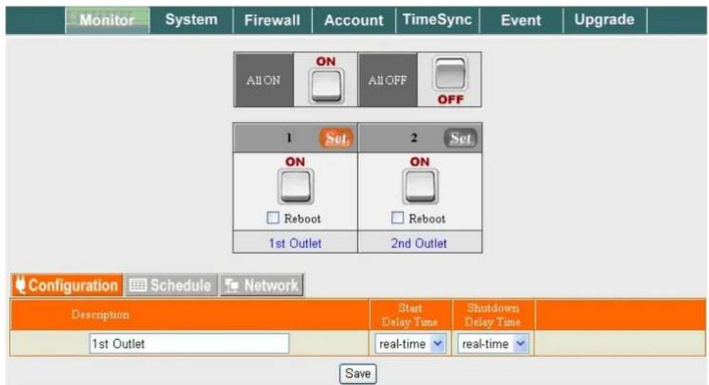
This page controls the power to the ports (receptacles). Each port can be manually powered ON/OFF or set to a pre-determined schedule.
Port Operation
Controls power to each port individually or both ports simultaneously. Selecting the "Reboot" option will toggle the port OFF, then switch it back ON after a short delay. To Configure the advanced options for each port, it must first be selected by highlighting the "Set" button above the port.
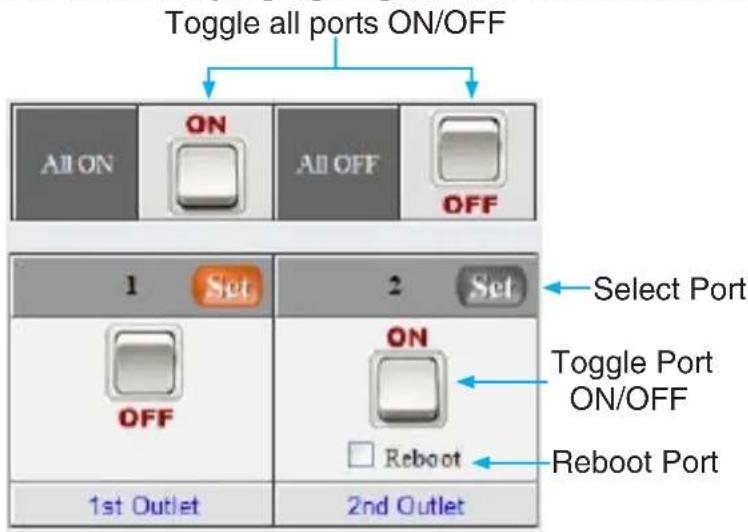
Configuration

Create a custom name for the selected port and specify a timer delay from when the port is powered ON/OFF.
Schedule

Create a recurring schedule to power ON/OFF/Reboot the selected port.
Network
If the device connected to the selected port is a network aware device, the Remote Power Switch can intermittently ping the IP address of the device to confirm that the device is operating.
System

Various networking, Email, and messaging services for the Remote Power Switch can be configured from this section.
Network

LAN, DNS and web interface access configuration for the Remote Power Switch can be completed in this section. This is an alternative to using the IP Search Utility.
Mail Setup
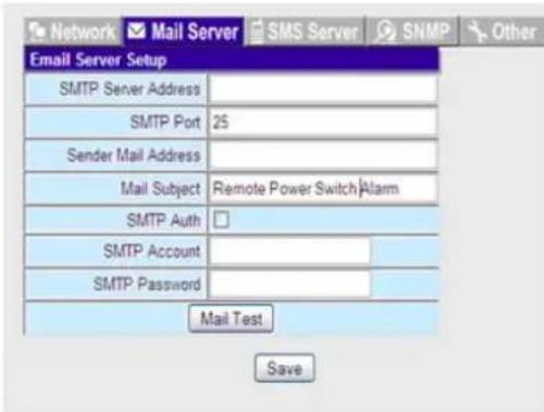
Email messaging service that will be triggered when a warning is generated by the Remote Power Switch. Configuration settings to setup the Remote Power Switch with your SMTP server are made here.
SMS Server

SMS text messaging service that will be triggered when a warning is generated by the Remote Power Switch. Configuration settings to setup the Remote Power Switch with your SMS messaging server are made here.
SNMP/SysLog

Configuration settings to setup the Remote Power Switch with your SNMP TRAP server and/or SysLog server are made here.
Other
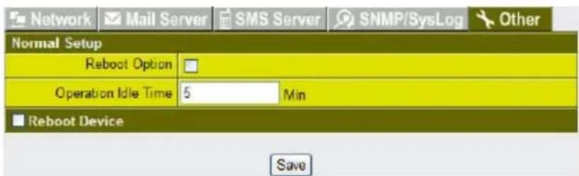
Allows for rebooting of the Remote Power Switch and setting the idle timeout for the web interface.
FireWall
IP Filter

Allow access from specific IP addresses on the LAN only.
MAC Filter

Allow access from specific hardware MAC addresses only.
Account

Create/edit additional user accounts for the Remote Power Switch, including contact cellphone number (for SMS service), email address and per port access control.
TimeSync

Set/configure the system time for the Remote Power Switch.
Event
![Refresh Download Delete Time Kind Message 01/01/1970 00:01:32 Port:1[1st Outlet] Power Off,Operator:Local User [admin][192.168.1.222] control by browser 01/06/2010 14:25:00 Port:2[2nd Outlet] Power On,Operator:Schedule 01/06/2010 14:23:32 Port:2[2nd Outlet] Power Off,Operator:Schedule 01/01/1970 00:17:55 Port:2[2nd Outlet] Power On,Operator:Local User [admin][192.168.1.222] control by browser 01/01/1970 00:17:55 Port:1[1st Outlet] Power On,Operator:Local User [admin][192.168.1.222] control by browser 01/01/1970 00:17:39 Port:2[2nd Outlet] Power Off,Operator:Local User [admin][192.168.1.222] control by browser 01/01/1970 00:17:39 Port:1[1st Outlet] Power Off,Operator:Local User [admin][192.168.1.222] control by browser 01/01/1970 00:17:22 Port:1[1st Outlet] Power On,Operator:Local User [admin][192.168.1.222] control by browser 01/01/1970 00:17:11 Port:1[1st Outlet] Power Off,Operator:Local User [admin][192.168.1.222] control by browser Port:1[1st Outlet] Power Reboot,Operator:Local User [admin][192.168.1.222] control](/content/2026/06/1247690/images/50b9392e5d17878b3d1b37168819996e7e6a90f7e6065c588432ac3f6ad0f2c6.jpg)
Event log of all activity performed on/by the Remote Power Switch from the last 7 days. The log can be downloaded and saved as a .CVS file on the host system.
Upgrade
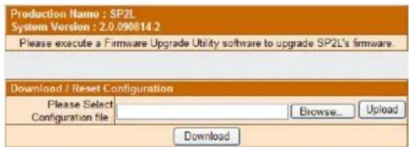
Lists the currently installed firmware version and allows for upload of newer versions available at www.startech.com.
Logout
Logout of the current session.
Factory Reset
If incorrect network settings are saved to the Remote Power Switch or are unable to log into the unit, all settings can be restored to the default state via the System Reset button on the unit itself. The System Reset button is located on the rear side, next to the LED indicators. Using a small object, such as a paperclip, press and hold down the System Reset button for 5 seconds.
Specifications
| Number of Ports | 2 |
| Input Power | 115 ~ 230VAC, 47 ~ 63Hz |
| Maximum Current Input | 12A |
| Maximum Current Output (per port) | 8A |
| Connectors | 1 x IEC C14 male2 x NEMA 5-15R female1 x RJ45 Ethernet |
| LEDs | 2 x Port Power status1 x Power1 x Reset/Fault Indicator |
| Rack Mountable | Yes |
| Operating Temperature | 0°C ~ 40°C (32°F ~ 104°F) |
| Storage Temperature | 0°C ~ 60°C (32°F ~ 140°F) |
| Humidity | 0 ~ 95% RH |
| Dimensions (WxHxD) | 182.6mm x 44.0mm x 129.0mm |
| Weight | 806g |
Technical Support
StarTech.com's lifetime technical support is an integral part of our commitment to provide industry-leading solutions. If you ever need help with your product, visit www.startech.com/support and access our comprehensive selection of online tools, documentation, and downloads.
Warranty Information
This product is backed by a one year warranty.
In addition, StarTech.com warrants its products against defects in materials and workmanship for the periods noted, following the initial date of purchase. During this period, the products may be returned for repair, or replacement with equivalent products at our discretion. The warranty covers parts and labor costs only. StarTech.com does not warrant its products from defects or damages arising from misuse, abuse, alteration, or normal wear and tear.
Limitation of Liability
In no event shall the liability of StarTech.com Ltd. and StarTech.com USA LLP (or their officers, directors, employees or agents) for any damages (whether direct or indirect, special, punitive, incidental, consequential, or otherwise), loss of profits, loss of business, or any pecuniary loss, arising out of or related to the use of the product exceed the actual price paid for the product. Some states do not allow the exclusion or limitation of incidental or consequential damages. If such laws apply, the limitations or exclusions contained in this statement may not apply to you.
StarTech.com Making hard-to-find easy!®
StarTech.com has been making “hard-to-find easy” since 1985, providing high quality solutions to a diverse IT and A/V customer base that spans many channels, including government, education and industrial facilities to name just a few. We offer an unmatched selection of computer parts, cables, A/V products, KVM and Server Management solutions, serving a worldwide market through our locations in the United States, Canada, the United Kingdom and Taiwan.
Visit www.startech.com today for complete information about all our products and to access exclusive interactive tools such as the Cable Finder, Parts Finder and the KVM Reference Guide.
- FCC Compliance Statement
- Use of Trademarks, Registered Trademarks, and other Protected Names and Symbols
- Table of Contents
- Introduction....1
- Installation....3
- Configuration 3
- How to Use .... 5
- Specifications....11
- Technical Support 12
- Warranty Information 12
- Introduction
- Packaging Contents
- System Requirements
- Front View
- Rear View
- Installation
- Hardware Installation
- Driver Installation
- Configuration
- IP Search Utility
- Web Browser
- How to Use
- Monitor
- Port Operation
- Schedule
- Network
- System
- Mail Setup
- SMS Server
- SNMP/SysLog
- Other
- FireWall
- IP Filter
- MAC Filter
- Account
- TimeSync
- Event
- Upgrade
- Logout
- Factory Reset
- Technical Support
- Warranty Information
- Limitation of Liability
- StarTech.com Making hard-to-find easy!®
Brand : StarTech.com
Model : IPRKPW0215
Category : Power Strip