
HDEXT50M - Audio / Video KanexPro - Free user manual and instructions
Find the device manual for free HDEXT50M KanexPro in PDF.


| Product Type | HDMI Extender |
| Model | HDEXT50M |
| Brand | KanexPro |
| Maximum Transmission Distance | 50 meters (164 feet) |
| Supported Resolution | Up to 1080p Full HD |
| Video Bandwidth | Up to 4.95 Gbps |
| Audio Support | Digital audio (coaxial or optical) via HDMI |
| Connector Type | HDMI (input/output), RJ45 (Ethernet) |
| Power Supply | 5V DC, 1A (via included adapter) |
| Power Consumption | 2.5W (max) |
| Dimensions (Transmitter) | 85 mm x 60 mm x 25 mm |
| Dimensions (Receiver) | 85 mm x 60 mm x 25 mm |
| Weight (each unit) | Approx. 120 g |
| Operating Temperature | 0°C to 50°C (32°F to 122°F) |
| Storage Temperature | -20°C to 60°C (-4°F to 140°F) |
| Humidity | 10% to 85% RH (non-condensing) |
| HDCP Support | HDCP 1.4 compliant |
| EDID Bypass | Built-in EDID management (default 1080p) |
| Surge Protection | ESD protection: ±8kV (air discharge), ±4kV (contact) |
| Housing Material | Metal chassis for EMI shielding |
| Included Accessories | 2x power adapters, IR blaster/extender cables, user manual |
| Warranty | Limited 1-year warranty |
Frequently Asked Questions - HDEXT50M KanexPro
User questions about HDEXT50M KanexPro
0 question about this device. Answer the ones you know or ask your own.
Ask a new question about this device
Download the instructions for your Audio / Video in PDF format for free! Find your manual HDEXT50M - KanexPro and take your electronic device back in hand. On this page are published all the documents necessary for the use of your device. HDEXT50M by KanexPro.
USER MANUAL HDEXT50M KanexPro
natural_image
Black electronic device with ports and a central port (no visible text or symbols)
natural_image
Black rectangular electronic device with ports and a network interface (no visible text or symbols)Extend HD Signals over CAT 5/5e/6 up to 164ft.(50m)
All Rights Reserved
Version: HDEXT50M_2017V1.2
Preface
Read this user manual carefully before using this product. Pictures displayed in this manual are for reference only. Different models and specifications are subject to the actual product.
This manual is only for operational instruction, not for any maintenance usage. The functions described in this version are updated till June 2016. Any changes of functions and parameters since then will be informed separately. Please refer to the dealers for the latest details.
All product function is valid till 2017-6-19.
Trademarks
Product model and logo are trademarks. Any other trademarks mentioned in this manual are acknowledged as the properties of the trademark owner. No part of this publication may be copied or reproduced without the prior written consent.
FCC Statement
This equipment can generate, use, and radiate radio frequency energy and, if not installed and used in accordance with the instructions, may cause harmful interference to radio communications. It has been tested and found to comply with the limits of a Class B digital device, pursuant to part 15 of the FCC Rules. These limits are designed to provide reasonable protection against harmful interference in a commercial installation.
Operation of this equipment in a residential area is likely to cause interference, in which case the user at their own expense will be required to take whatever measures may be necessary to correct the interference
Any changes or modifications not expressly approved by the manufacture would void the user's authority to operate the equipment.

SAFETY PRECAUTIONS
To ensure the best from the product, please read all instructions carefully before using the device. Save this manual for further reference.
- Unpack the equipment carefully and save the original box and packing material for probable future shipment.
- Follow basic safety precautions to reduce the risk of fire, electrical shock and injury to persons.
- Do not dismantle the housing or modify the module. It may result in electrical shock or burn.
- Using supplies or parts not meeting the products' specifications may cause damage, deterioration or malfunction.
● Refer all servicing to qualified service personnel.
- To prevent fire or shock hazard, do not expose the unit to rain or moisture. Do not install this product near water.
- Do not place any heavy items on the extension cable in case of extrusion.
- Do not remove the housing of the device as opening or removing housing may expose you to dangerous voltage or other hazards.
- Install the device in a place with fine ventilation to avoid damage caused by overheating.
- Keep the module away from liquids.
- Spillage into the housing may result in fire, electrical shock, or equipment damage. If an object or liquid falls or spills on to the housing, unplug the module immediately.
- Do not twist/pull by force the ends of the optical cable. It can cause malfunction.
- Do not use liquid or aerosol cleaners to clean this unit. Always unplug the power cord to the device before cleaning.
● Unplug the power cord when left unused for an extended period.
● Information on disposal for scrapped devices: Do not burn or mix with general household waste; please treat the devices as normal electrical waste.
Table of Contents
- Introduction......5
1.1 Introduction to HDEXT50M 5
1.2 Features....5
1.3 Package List....6
-
Panel Description ....6
-
System Connection ....7
3.1 Usage Precautions....7
3.2 System Diagram....7
3.3 Connection Procedure 8
-
Specification 8
-
Troubleshooting & Maintenance....9
-
After-sales Service....10
-
Warranty 11
1. Introduction
1.1 Introduction to HDEXT50M
1.2 Features
- Extend DVI/HDMI over cost-effective Cat5 cable up to 164 ft. (50m)
■ Supports full HD 1080p (1920x1080@60Hz)
■ Local HDMI output (loop out) - Supports PoC – receiver can we powered via the transmitter
■ Built-in EDID to ensure proper HDMI transmission
■ Built in EQ button on the side to compensate for signal equalization
■ Digital audio support through HDMI
■ HDCP 1.4 compliant
■ Bi-directional wideband IR control - Plug & Play - no set-up required
■ Includes IR kits & one Micro USB power supply
1.3 Package List
- 1 x Transmitter
- 1 x Receiver
• 1 x Wideband IR TX cable
• 1 x Wideband IR RX cable
- 1 x Power adapter (DC 5V 1A)
- 1 x User Manual
Note: If there are defective parts or parts are missing, please contact your local dealer(s).
2. Panel Description
Transmitter (TX)
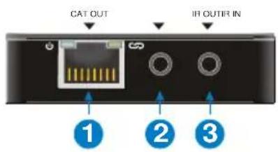

① CAT OUT: RJ45 connector with Green (when powered on) & Yellow (when linked successfully between transmitter and receiver) indicators. Connect to Receiver over CATx cable.
② IR IN: Connect with IR Receiver.
③ IR OUT: Connect with IR Emitter.
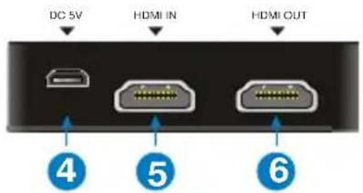
④ DC 5V: Micro USB, connect to the power adaptor.
⑤ HDMI IN: Connect to HDMI source.
⑥ HDMI OUT: HDMI loop output, connect to display.
⑦ RESET: Reboot.
Receiver (RX)
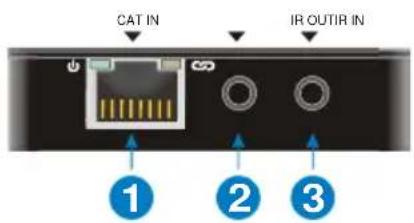
① CAT IN: RJ45 connector with Green& Yellow indicators. Connect to Transmitter over CATx cable.
② IR IN: Connect with IR Receiver.
③ IR OUT: Connect with IR Emitter.
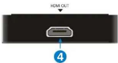
④ HDMI OUT: Connect to display.
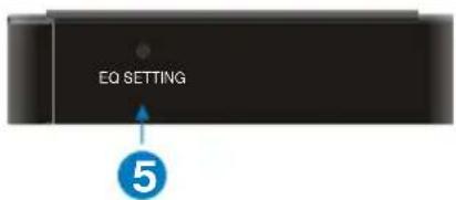
⑤ EQ SETTING: After the system is connected, press this button three to six times repeatedly until the best image output. When the cable, source, or display is changed, or reset the output resolution, it is need to press this button repeatedly to ensure the best image.
Pictures shown in this manual are only for reference.
3. System Connection
3.1 Usage Precautions
■ System should be installed in a clean environment, which should have a proper temperature and humidity.
- All the power switches, plugs, sockets and power cords should be insulated and safe.
■ All devices should be connected before powered on.
■ System Diagram shown in this manual is for reference only; more specific schemes depend on real-time applications.
3.2 System Diagram

flowchart
graph TD
    A["DC 5V"] --> B["IR Emitter"]
    B --> C["DisplayDVO"]
    C --> D["1000P 55m"]
    D --> E["IR Receiver Projector Remote"]
    E --> F["Projector"]
    F --> G["IR Emitter"]
    G --> H["DisplayDVO"]
    H --> I["1000P 55m"]
    I --> J["PeC"]
    style A fill:#f9f,stroke:#333
    style B fill:#ccf,stroke:#333
    style C fill:#cfc,stroke:#333
    style D fill:#fcc,stroke:#333
    style E fill:#cff,stroke:#333
    style F fill:#ffc,stroke:#333
    style G fill:#fcc,stroke:#333
    style H fill:#ffc,stroke:#333
    style I fill:#fcc,stroke:#333
3.3 Connection Procedure
Step1. Connect HDMI source devices (Gaming consoles, DVD players, etc.) to the HDMI input ports on the Transmitter.
Step2. Connect a CAT5e/6 cable to the CAT5e/6 port on both the Transmitter and the Receiver.
Step3. Connect HDMI display (HDTV, projector, monitor, etc.) to the HDMI output on the Receiver unit.
Step4. Connect the 5V power supply LAST to both units and power on the devices.
4. Specification
| Transmitter | Receiver | |
| Input | (1) HDMI | (1) HDBaseT |
| Input Connector | (1) 19-pin type-A female HDMI | (1) RJ45 |
| Output | (1) HDMI; (1) HDBaseT | (1) HDMI |
| Output Connector | (1) 19-pin type-A female HDMI; (1) RJ45 | (1) 19-pin type-A female HDMI |
| Control | (1) IR IN; (1) IR OUT | (1) IR IN; (1) IR OUT |
| Control Connector | (2) 3.5mm mini jacks | (2) 3.5mm mini jacks |
| General | ||
| Transmission Distance | 1080p@60Hz≤55m | |
| HDMI Standard | HDMI1.4, HDCP1.4 compliant | |
| EDID Management | Built-in EDID | |
| Power Supply | Input: 100VAC~240VAC, 50/60Hz; Output: 5VDC 1A | |
| Power Consumption | 4W (Max) | |
| Work Temperature | -10~55C° | |
| Reference Humility | 10%-90% | |
| Dimensions (W*H*D) | 66mm x 16.8 mm x66 mm | |
| Weight | Transmitter: 36g; Receiver: 38g; | |
5. Troubleshooting & Maintenance
| Problems | Causes | Solutions |
| Output images in display show with ghost | Incorrect setting on the display | Check the display's setting |
| A cable of inferior quality | Try another high-quality connection cable | |
| No output image when switching | No signal at the input / output end | Check with oscilloscope or multimeter if there is any signal at the input / output end. |
| Fail or loose connection | Make sure the connection is good | |
| The extender is defective | Send it to authorized dealer for repairing. | |
| Static becomes stronger when connecting the video connectors | Bad grounding | Check the grounding and make sure it is connected well. |
If your problem persists after following the above troubleshooting steps, seek further help from authorized dealer or our technical support.
6. After-sales Service
If problems arise when operating the device, please refer to this user manual. Any transport costs are borne by the users during the warranty.
① Product Limited Warranty: We warrant that products will be free from defects in materials and workmanship for three years, which starts from the first day the product exits warehouse. (Make note of the serial number on the product) Proof of purchase in the form of a bill of sale or receipted invoice MUST be presented to obtain warranty service.
② What the warranty does not cover:
● Warranty expiration.
● Factory applied serial number has been altered or removed from the product.
● Damage, deterioration or malfunction caused by:
● Normal wear and tear
● Use of supplies or parts not meeting our specifications
● No certificate or invoice as the proof of warranty.
● The product model showed on the warranty card does not match with the model of the product for repairing or had been altered.
● Damage caused by force majeure.
● Servicing not authorized
● Any other causes which does not relate to a product defect
● Delivery, installation or labor charges for installation or setup of the product.
③ Technical Support: Email or call our after-sales department if there are any problems or any unanswered questions. Please inform us the following information about your cases:
● Product version and name.
● Detailed failure situations.
● The formation of the cases.
Remarks: For any questions or problems, please try to get help from your local distributor or contact kanexpro.com or call us at 888-975-1368 for further support.
7. Warranty
A. LIMITED WARRANTY
KanexPro™ warrants that (a) its products (the "Product") will perform greatly in agreement with the accompanying written materials for a period of 36 months (3 full years) from the date of receipt and (b) that the product will be free from defects in materials and workmanship under normal use and service for a period of 3 years.
B. CUSTOMER REMEDIES
KanexPro's entire liability and Customer's exclusive remedy shall be, at KanexPro option, either return of the price paid for the product, or repair or replacement of the Product that does not meet this Limited Warranty and which is returned to KanexPro with a copy of customers' receipt. This Limited Warranty is void if failure of the Product has resulted from accident, abuse, or misapplication. Any replacement Product will be warranted for the remainder of the original warranty period of 3 years, whichever is longer.
C. NO OTHER WARRANTIES
To the maximum extent permitted by applicable law, KanexPro disclaims all other warranties, either express or implied, including, but not limited to implied warranties of merchantability and fitness for a purpose, regarding the product and any related written materials. This limited warranty gives customers specific legal rights. Customers may have other rights depending on the jurisdiction.
D. NO LIABILITY FOR DAMAGES
To the maximum extent permitted by applicable law, in no event shall KanexPro be liable for any damages whatsoever (including without limitation, special, incidental, consequential, or indirect damages for personal injury, loss of business profits, business interruption, loss of business information, or any other pecuniary loss) arising out of the use of or inability to use this product, even if KanexPro has been advised of the possibility of such damages.
KanexPro
1405 pioneer street
Brea, CA 92821

- Preface
- Trademarks
- FCC Statement
- SAFETY PRECAUTIONS
- Table of Contents
- Introduction
- Introduction to HDEXT50M
- Features
- Package List
- Panel Description
- System Connection
- Usage Precautions
- System Diagram
- Connection Procedure
- Specification
- Troubleshooting & Maintenance
- After-sales Service
- Warranty
- LIMITED WARRANTY
- CUSTOMER REMEDIES
- NO OTHER WARRANTIES
- NO LIABILITY FOR DAMAGES
- KanexPro
Brand : KanexPro
Model : HDEXT50M
Category : Audio / Video