
HC24TB-4-1R-1 - Beer Pump Perlick - Free user manual and instructions
Find the device manual for free HC24TB-4-1R-1 Perlick in PDF.


| Product Type | Undercounter Beer Dispenser |
| Brand | Perlick |
| Model | HC24TB-4-1R-1 |
| Width | 24 inches (61 cm) |
| Depth | 24 inches (61 cm) |
| Height | 32.5 inches (82.6 cm) |
| Weight | 120 lbs (54.4 kg) |
| Power Supply | 115V / 60 Hz / 1.5A |
| Number of Taps | 4 |
| Cooling Type | Forced air refrigeration |
| Temperature Range | 34°F - 40°F (1°C - 4°C) |
| Refrigerant | R290 (hydrocarbon) |
| Construction | Stainless steel interior and exterior |
| Included Accessories | Beer tower, drip tray, CO2 regulator, keg couplers |
| Installation Type | Undercounter (ventilated front grille) |
| Cleaning | Use mild soap and warm water; avoid abrasive cleaners |
| Safety Features | Automatic defrost, high-pressure cut-off switch |
| Spare Parts Availability | Faucets, towers, CO2 regulators, cooling fans available |
| Warranty | 1 year parts and labor |
| Certifications | NSF, UL, Energy Star qualified |
Frequently Asked Questions - HC24TB-4-1R-1 Perlick
User questions about HC24TB-4-1R-1 Perlick
0 question about this device. Answer the ones you know or ask your own.
Ask a new question about this device
Download the instructions for your Beer Pump in PDF format for free! Find your manual HC24TB-4-1R-1 - Perlick and take your electronic device back in hand. On this page are published all the documents necessary for the use of your device. HC24TB-4-1R-1 by Perlick.
USER MANUAL HC24TB-4-1R-1 Perlick
natural_image
Interior view of a refrigerated beverage rack with illuminated shelves and stacked bottles (no visible text or labels)
natural_image
Interior view of a modern kitchen appliance with a glass refrigerator and wine glasses (no visible text or symbols)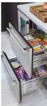
natural_image
Interior view of a modern kitchen appliance showing a double-door refrigerator with food compartments and a tray (no visible text or labels)PERLICK RESIDENTIAL UNDERCOUNTER REFRIGERATION



Perlick
PERLICK RESIDENTIAL UNDERCOUNTER INSTALLATION MANUAL
GENERAL INFORMATION
Introduction
Congratulations on your purchase of a Perlick Residential undercounter product. This manual has been prepared to assist you in the installation of your cabinet and to acquaint you with its operation and maintenance.
This manual has been prepared to assist you in the installation of your under counter refrigerator and to acquaint you with its operation and maintenance.
We dedicate considerable time to ensure that our products provide the highest level of customer satisfaction. If service is required, your dealer can provide you with a list of qualified service agents. For your own protection, never return merchandise for credit without our approval.
We thank you for selecting a Perlick product and assure you of our continuing interest in your satisfaction.
Warranty
To register your product, visit our web site at www.perlick.com. Click on "Residential", then "Resources". Click on the link "Warranty Registration Form". You must complete and submit this form or the installation date will revert back to the ship date.
Please record the purchase date and the dealer's name, address and telephone number below.
Model Number: ____
Serial Number: ____
Purchase Date: ____
Dealer Name & Address ____
Phone Number ____
TABLE OF CONTENTS
General Information....2
Safety 3
Refrigerant 3
Prior To Installation 3
Preparing the Cabinet for Use
Uncrating and Inspection 4
Electrical....4
Use and Operation....4
Repair & Maintenance 5
SAFETY
PLEASE READ all instructions completely before attempting to install or operate the unit. Take particular note of the DANGER, WARNING and CAUTION information in the manual. The information is important for the safe and efficient installation, operation and care of your Perlick unit.
DANGER
Indicates a hazard that WILL result in serious injury or death if it followed.
WARNING
Indicates a hazard MAY cause serious injury or death if followed.
precautions are not
CAUTION
Indicates a hazard where minor or moderate injury may occur if followed.
precautions are not
NOTICE
Indicates that property damage may occur if warnings or followed.
instructions are not followed.
IMPORTANT!
Read and understand all information in this manual before attempting the installation. All plumbing and electrical work must be performed by a qualified technician and conform to all applicable state and local codes.
Refrigerant
DANGER
Take caution when handling, moving and using the product to be refrigerant tubing or increasing
avoid damaging the refrigerant tubing or increasing the risk of a leak
WARNING
All service work shall be performed by factory authorized
service personnel and all component parts shall be replaced with like components to minimize the risk of possible ignition due to incorrect parts or improper service.
CAUTION
If service is necessary, repair work must be performed by a Perlick
authorized servicer. Work done by unqualified individuals could potentially be dangerous and will void the warranty.
All models covered in this user manual are manufactured using refrigerant R600a(Isobutane). R600a is a hydrocarbon. This refrigerant is flammable and is only allowed for use in appliances with fulfill the requirements of UL/IEC 60335-1 and UL/IEC 60335-2-24. (To cover potential risk originated from the use of flammable refrigerants). Consequently, R600a is only allowed to be used in refrigerating appliances with are designed for this refrigerant and fulfill the above-mentioned standard.
• R600a is heavier than air. The concentration will always
be highest at the floor level.
- The explosion limits are as follows:
o Lower Limit: 1.8% by volume
o Upper Limit: 8.4% by volume
o Ignition Temperature: 460°C
Perlick
PERLICK RESIDENTIAL UNDERCOUNTER INSTALLATION MANUAL
Preparing the Cabinet for Use
UNCRATING AND INSPECTION
Remove all crating material before operating. Carefully inspect cabinet for hidden damage. If damage is discovered, file your claim immediately with the transport company. Perlick is not responsible for damage in transit.
DANGER
Do not use or store flammable liquids (ie; gasoline) or vapors to avoid fire.
INSTALLATION
NOTICE The unit must NOT be totally enclosed or damage may occur. Air circulation must not be restricted. The condenser at cabinet front must be provided with a minimum of two inches air space. Be sure to provide access so front cover can be removed to clean the condenser.
NOTICE
If unit has been laid on its back or sides, place unit upright and allow hours before connecting power. This procedure may damage the id the warranty.
NOTICE
Use care when handling, moving and using the product to avoid gerant tubing or increasing the risk
PLUMBING
No plumbing connections are required. Condensate from the cooling coil is automatically evaporated through a condensate pan located in the condensing section of the unit.
WARNING
Never use an extension cord to connect the unit to the electrical
source. Do not use a two-prong adapter or remove the power cord ground prong. Failure to use grounding may result in death, serious injury, or property damage.
NOTICE
Using any voltage other than specified will result in serious
damage to the unit.

Figure 1. HH (Sottile Model) Electrical Connections
USE & OPERATION
DANGER
Do not use or store flammable liquids (ie; gasoline) or vapors
near the appliance to avoid fire.
REPAIR & MAINTENANCE
WARNING
All service work shall be performed by Perlick-authorized service
personnel. All component parts shall be replaced with like components. Incorrect parts or improper service may result in fire.
INSTALLING CASTERS OR LEGS (OPTIONAL)
Attach bracket assembly to the bottom of the cabinet base using the 1/4"-20 Philips head machine screws provided. Attach casters or legs to the mounting bracket with 1/4"-20 Philips head screws provided
NOTICE
Anti-tip brackets are only used for stationary cabinets and should not
be installed on cabinets with accessory casters. Caster kits are available for HP, HC and HA model cabinets. Refer to the instructions supplied with the caster kit for proper installation.
NOTICE
If installing on a concrete floor, concrete fasteners are required and
not included with the anti-tip kit.
NOTICE
Some installation sites may require modifications to provide a secure
surface for attaching the brackets.
A set of anti-tip brackets is supplied with the unit. These brackets should be attached to the floor at the rear of the unit. Each bracket must be located to engage the rear
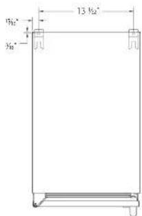
Figure 2A. 15" Anti-lip Kit

Perlick
PERLICK RESIDENTIAL UNDERCOUNTER INSTALLATION MANUAL
PREPARING THE SPACE
CAUTION If the unit is to be installed under a countertop, it is recommended that the countertop be supported by surrounding cabinetry and use shims to support countertop directly above the refrigerated cabinet.
CAUTION Make sure the floor under the unit is level with the surrounding finished floor. Protect a finished floor with plywood, cardboard, or some other suitable material before moving the unit into place. Failure to do this may result in damage to the floor.
PLACING THE CABINET
To assure maximum performance, fresh air must be allowed to circulate through the machinery compartment. Do not place anything in front of the cabinet that would obstruct air flow at these grilles. Do not place the unit in an unventilated small room.
NOTICE
Cabinet should be leveled front to back then side to side
1). Make sure the space opening is correctly sized for the unit. See chart below for finished rough opening requirements:
| HP15 15" Signature Series | ||
| Height Depth Width | ||
| 34 3/8' minimum,35-1/2' maximum | 24" 15" | |
| HP24 24" Signature Series | ||
| Height Depth Width | ||
2). Check that the following are level and square:
- Front and interior opening
• Installation opening and floor surface - Countertop bottom front edge
NOTE: The floor under the unit must be at the same level as the surrounding finished floor.
⚠️ CAUTION To prevent possible damage to the countertop, do not place heavy objects on countertop directly over unit.
INSTALLING THE UNIT
1) Plug the unit into the 15 amp grounded electrical outlet located within the installation opening. With power applied to the unit, check that the lighting and cooling functions operate properly. Turn off the power to the wall outlet at the circuit breaker.
2) With all surfaces in the installation opening square and level, refer to Figure 4 on page 7 and perform the following steps to level the unit:
- At the front of the opening, measure from the floor to the bottom of the front edge of the countertop.
- Measure from the floor surface to the top of the unit at the rear corners.
- Adjust the unit legs so these two measurements are equal. Using an adjustable wrench or pliers, turn legs clockwise to lower the unit or counterclockwise to raise it.
NOTE: Legs should not extend more than 3/4" from the bottom of the unit.
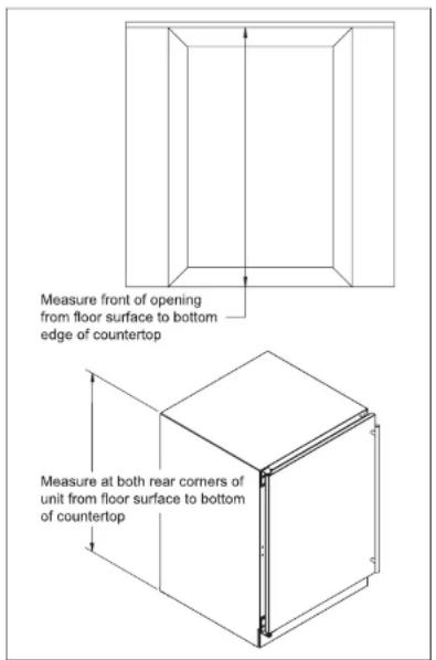
Figure 4. Leveling the Unit
5) Check interior door openings to make sure the unit is level and square. Install shelving and/or drawers. Place the slide brackets squarely into the bracket grooves.
TOE PLATE INSTALLATION
Once the unit is secured in place, install the louvered toe plate. Secure the plate by snapping the latch into the latch catch on the unit, and re-attach screws using through holes provided in the toe kick. A phillips #2 screwdriver, with a 3" long shaft will be required. (Figure 5).
CAUTION The toe plate must be removed to service the unit. The floor cannot interfere with removal, and the louvered sections must not be covered or obstructed. Obstructions could prevent proper air circulation, which may damage the unit.
NOTE: To achieve maximum performance, interior louver openings and fan guard openings should never be obstructed.

natural_image
Technical line drawing of a mechanical device with ventilation grilles and mounting bracket (no text or symbols)Figure 5. Toe Kick Installation
Perlick
PERLICK RESIDENTIAL UNDERCOUNTER INSTALLATION MANUAL
SHELVING/DRAWER ADJUSTMENTS
CAUTION
Completely empty shelf or drawer before removing.
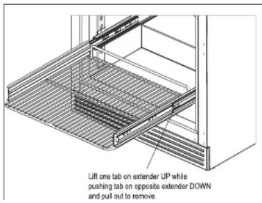
- Pull the shelf/drawer out to its furthest position. Locate the tabs in the middle of both extenders. Lift one tab up while pushing the opposite tab down, and pull shelf/drawer out (Figure 6).
- Position each bracket separately. Grasp the middle of the bracket, pull the front end up and out, then forward to remove it.
- Place bracket at desired location. Push the bracket rear hook into the rear mounting slot, then set front of the bracket in the front slot.
- Repeat for other brackets.
- Push extenders completely into brackets. Align the shelf/drawer grooves with the extenders and slide completely into the unit.
DOOR OPTIONS
Perlick residential units offer a variety of door panel design alternatives; solid stainless steel, solid wood overlay, glass with stainless steel trim and glass with wood overlay trim.
Solid stainless steel and stainless steel glass doors are shipped from the factory with decorative stainless steel panels and handles in place on the unit. Solid wood overlay and glass wood overlay doors are designed to accept a decorative front panel to match surrounding cabinetry and door handles.
NOTE: Wood overlay models are designed to accept wood overlay panels from your cabinetry supplier. They do not include a wood overlay. Templates are available on www.perlick.com/residential-products. Click on Service & Support, and then choose Wood Overlay Templates from the menu. Take care in choosing the correct template for your specific model. The handle is supplied by the customer.
All Perlick units (excluding beer dispenser and ice maker models) accept any of the above door configurations and are fully interchangeable. Glass door configurations are not available on beer dispenser or ice maker models.
NOTE: Glass with stainless steel trim and glass with wood trim may sweat in conditions with relative humidity over 75%.
CHANGING DOOR SWING DIRECTION
NOTE: Changing the door mount is not advisable if the door is equipped with a custom wood overlay. Doing so may result in an undesirable handle position.
To change the door swing direction, a hinge kit is required:
• Part No. 67439R - Right hinge kit

Figure 7. Door Removal
5) Using the screws removed in step 3, install the top and bottom hinge brackets from the kit (Fig. 9).

Figure 9. Hinge Installation

6) Remove the top and bottom door hinge brackets and the push plunger brackets (Fig. 10). Retain the screws for later use.

natural_image
Simple line drawing of a door frame with a small object on the side (no text or symbols)Perlick
PERLICK RESIDENTIAL UNDERCOUNTER INSTALLATION MANUAL
7) Remove the front panel from the door assembly by removing the door gasket and then removing the overlay mounting screws, 4 per side, from the perimeter of the door assembly (Fig. 11). Rotate the front panel 180°. The top becomes the bottom. Reattach using the same screws and mounting holes and then reinstall the door gasket.
9) Insert the bearing into the door hinge bracket (Fig. 13).
10). Insert the V-block into the door bottom hinge bracket and attach with the e-clip (Fig. 13). Note the orientation of the V-block.

Figure 11. Removing Front Panel

Figure 13. Bearing and V-Block
11) Attach the top and bottom hinges and push plunger using screws removed in step 6 (Fig. 14).
8) Remove the Perlick nameplate from the door front using a plastic putty knife (Fig. 12). Install the new Perlick nameplate included in the kit.

12) Place the lower V-block into the lower cabinet hinge with the notch parallel to the cabinet (Fig. 15).

Figure 15. Installing V-Block
13) Lift the door assembly and insert the top pin into the bearing. Move door toward cabinet and align the V-blocks (Fig. 16).
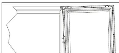
natural_image
Pure architectural line drawing of a window frame structure without any text or symbolsHANDLE INSTALLATION
CAUTION The handle mounting on the wood overlay should be mounted on the overlay only (not the actual door) to avoid damage to the factory door.
- Handle must be attached to the overlay before mounting the overlay onto the door. Mark the rear of the wood overlay panel with handle fastening locations.
- Drill through the wood overlay panel at marked locations, taking care not to damage the panel.
- Countersink screw heads so that screw heads are flush with the back side of the panel. Attach the handle to the overlay panel.
CAUTION Proper woodworking materials and equipment should be used to avoid damage or errors in workmanship.
DOOR LOCK INSTALLATION
NOTE: Full size lock installation wood overlay panel templates are available on the Perlick website. Visit www.perlick.com/Residential, click on Service & Support, and then choose Wood Overlay Templates from the menu. Lock templates are available for all HP, HC, HA and HH series models. Take care in choosing the correct template for your specific model.
When installing to a wood overlay, perform the lock installation before mounting the wood overlay to the door!
- See Figure 17 below. Attach mounting bracket to wood overlay.
- Insert lock body and attach with nut.
Perlick
PERLICK RESIDENTIAL UNDERCOUNTER INSTALLATION MANUAL
WOOD OVERLAY INSTALLATION
Before beginning installation, check all components for proper fit and finish. Handle should be installed to the overlay prior to installing overlay to door (use countersunk flathead fasteners for handle installation.)
CAUTION
For best performance and
should be 3/4" thick. The weight of the overlays should not exceed 20 lbs for solid (-2) doors, 10 lbs for glass (-4) doors, or 10 lbs for drawer (-6) models.
- -2, -4 and -6 models come ready to accept wood overlay as shown below.

natural_image
Exterior view of a rectangular metal frame with a blank white panel, placed on a pallet (no visible text or symbols)-
Remove the gasket carefully starting at the corners and avoid ripping the dart.
-
In some cases, the dart on the gasket may rip. If this happens, replace with a new gasket.

natural_image
Close-up of a damaged metal bracket with visible cracks and debris (no text or symbols)- With the gasket removed, the screw holes needed to hold the overlay panel will be reveal as shown below.
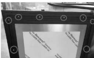
- Loosely attached the four corners of the overlay panel with the door frame with #10 x 3/4" wood screws.

- After alignment is satisfied, fasten down all screws through the screw holes.
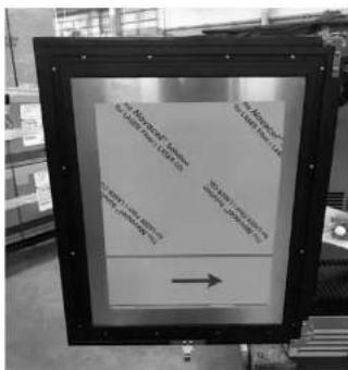
CAUTION Do not overtighten wood overlay attachment screws, as this may damage the factory supplied door frame.
- Make sure the overlay panel is aligned properly with the door.
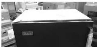
natural_image
Black refrigerator with lid and visible label, no readable text or symbols on the device itself- When re-installing the gasket, make sure the dart is pressed inside the slot on the door frame. Start at the four corners and firmly press your way inwards.

Parlick
PERLICK RESIDENTIAL UNDERCOUNTER INSTALLATION MANUAL
- Verify that the gasket is fully seated onto the door frame when completed.

natural_image
Close-up of a metallic mechanical component with layered grooves and a hand holding a small circular object (no visible text or symbols)- After installation of the overlay panel is completed, verify that the gasket is completely sealing around the cabinet frame. If installing panels onto drawer models (-6), repeat installation process for second drawer face. Installation is now complete.

natural_image
Close-up of a metallic sheet with visible cutting edge and surface texture (no text or symbols)WINE RACK TRIM (OPTIONAL)
All wine reserve racks come with sleek stainless steel fronts. Unfinished solid hardwood fronts are optional and can be removed and replaced with other wood to match your cabinetry. See Figure 18 and 19 for wine rack face details.
NOTE: The unfinished faces should be finished and sealed. In many cases, stains and/or finishes have odors that may be objectionable in an enclosed area. Do not stain or finish wood faces while installed on unit. To remove the front wood face from the wine shelf, simply pull out the wine shelf and remove the fasteners, finish as desired, and when completely dry, reinstall with fasteners.

Figure 18. Wine Rack Trim, 15" models

Signature Series products come equipped with a master power switch located behind the louvered toe kick. Remove the toe kick to turn power on or off to the unit. To remove the toe kick. Remove the two screws located in the through holes on the edge of the toe kick, near the latch strikes. A #2 Phillips screw driver with a 3" shaft will be required for remove the toe kick.
INTERIOR LIGHT
Door units are equipped with an interior light that illuminate when the door is opened. All models come standard with adjustable blue and white LED lighting. The cabinet also comes equipped with a manual light switch for displaying the products through a glass door.
Always ensure that the manual light switch is in the OFF position before closing a solid wood or stainless steel door. If manual light switch is left on for an extended period of time, it will increase energy usage and decrease LED life.
LOADING PRODUCT
Before storing perishables, turn unit on and allow it to operate for a minimum of 24 hours to allow temperatures to stabilize. When loading items into the unit, do not block internal louvers and fan guard openings or performance will be decreased.
CHECKING PRODUCT TEMPERATURE
1) To accurately check the temperature of product stored in the refrigerated compartment, insert an accurate thermometer into a plastic unbreakable bottle, partially filled with water. Tighten
Programming Button Definitions:
SET
SET Button

DEFROST button (melting snowflake)

UP Arrow

DOWN Arrow
ON/OFF Button
Signature Series Dual-Zone Control Instructions
On/Off
Press the ON/OFF button to turn the unit on or off.
Upper Compartment:
To view the upper compartment temperature, press and release the DEFROST button (melting snowflake).
Lower Compartment (Must be coldest zone):
Display reading always shows the lower compartment temperature.
Changing the Lower Compartment Temperature:
-
Press and hold the SET button until the display shows St1 with "F" flashing.
-
Press SET again to display the lower compartment's current temperature ("F" will continue to flash).
Perlick
PERLICK RESIDENTIAL UNDERCOUNTER INSTALLATION MANUAL
NOTE: Dependent on the model and configuration, the controllers have been programmed to only allow a lower compartment temperature adjustment range as specified within the chart below. The upper compartment range is not limited, but should always be kept within the specified range shown in the table for the upper compartment. See the chart below for the specified range allowed for your unit.
| Signature Series – Dual-Zone Units | |
| Model | Range (F) |
| HF24Z | Upper 33irc - 42irc F / Lower -10irc - 10irc F |
| HF24C | Upper 45irc 65irc F / Lower 33irc 42irc F |
| HF24D | Upper 51irc - 65irc F / Lower 45irc - 53irc F |
Temperature Scale
To change F to C, press and hold the down arrow for 3 seconds.
To Start A Manual Defrost (HP24Z Models Only)
Press and hold the DEFROST button (melting snowflake) for 3-5 seconds. Melting snowflake will illuminate.
15", 24" Single Zone, 24" Shallow Depth, and ADA Controls
To Set Target Temperature
Press and release the SET button. Display will show the current temperature setpoint.
To Change Setpoint Temperature
- Press and hold the SET button until the display shows the current setpoint temperature with the "F" flashing.
- Use the UP and DOWN arrow button to scroll to the desired temperature.
To Start A Manual Defrost (Freezer Models Only)
Press the DEFROST button (melting snowflake).
| Signature Series - HP15 Models | |
| Model Min Temp Set Max Temp Set | |
| HP15R 33° F 47° F | |
| HP15B 33° F 48° F | |
| HP15W 45° F 65° F | |
| HP15T 33° F 42° F | |
| Signature Series - HP24 Models | |
| Model Min Temp Set Max Temp Set | |
| HP24R 33° F 42° F | |
| HP24F -10° F 14° F | |
| HP24B 33° F 48° F | |
| HP24W 45° F 65° F | |
| HP24T 33° F 42° F | |
| Signature Serles Shallow Depth | |
| Model Min Temp Set Max Temp Set | |
| HH24RS 33° 42° | |
| HH24RS 33° 48° | |
| HH24WS 45° 65° | |
| C-Series Models | |
| Model Min Temp Set Max Temp Set | |
| HC24R3 33° 42° | |
| HC24RB 33° 48° | |
| HC24WB 45° 65° | |
| ADA-Compliant Series | |
| Model Min Temp Set Max Temp Set | |
| HA24FB -10° 10 | |
| HA24RB 33° 42° | |
| HA24BB 33° 48° | |
| HA24WB 45° 65° | |
LED Functions
PERLICK RESIDENTIAL UNDERCOUNTER INSTALLATION MANUAL
Perlick
NOTES

natural_image
Interior view of a refrigerated beverage shelf with illuminated bottles and glass (no visible text or labels)
natural_image
Interior view of a stainless steel refrigerator with open doors and glassware on the wall (no visible text or symbols)
natural_image
Interior view of a refrigerated kitchen drawer with open doors filled with various food items (no visible text or labels)
- GENERAL INFORMATION
- Introduction
- Warranty
- TABLE OF CONTENTS
- SAFETY
- DANGER
- WARNING
- CAUTION
- NOTICE
- IMPORTANT!
- Refrigerant
- Preparing the Cabinet for Use
- UNCRATING AND INSPECTION
- INSTALLATION
- PLUMBING
- USE & OPERATION
- REPAIR & MAINTENANCE
- INSTALLING CASTERS OR LEGS (OPTIONAL)
- PREPARING THE SPACE
- PLACING THE CABINET
- Cabinet should be leveled front to back then side to side
- INSTALLING THE UNIT
- TOE PLATE INSTALLATION
- SHELVING/DRAWER ADJUSTMENTS
- DOOR OPTIONS
- CHANGING DOOR SWING DIRECTION
- Perlick
- HANDLE INSTALLATION
- DOOR LOCK INSTALLATION
- WOOD OVERLAY INSTALLATION
- Parlick
- WINE RACK TRIM (OPTIONAL)
- INTERIOR LIGHT
- LOADING PRODUCT
- CHECKING PRODUCT TEMPERATURE
- Programming Button Definitions:
- SET
- Signature Series Dual-Zone Control Instructions
- On/Off
- Upper Compartment:
- Lower Compartment (Must be coldest zone):
- Changing the Lower Compartment Temperature:
- PERLICK RESIDENTIAL UNDERCOUNTER INSTALLATION MANUAL
- Temperature Scale
- To Start A Manual Defrost (HP24Z Models Only)
- 15", 24" Single Zone, 24" Shallow Depth, and ADA Controls
- To Set Target Temperature
- To Change Setpoint Temperature
- To Start A Manual Defrost (Freezer Models Only)
Brand : Perlick
Model : HC24TB-4-1R-1
Category : Beer Pump