
69526-3P - Beer Pump Perlick - Free user manual and instructions
Find the device manual for free 69526-3P Perlick in PDF.

| Product Type | Beer Dispensing Tower (Draft Arm, Tee Tower, Lucky, Panther) |
| Model Number | 69526-3P |
| Brand | Perlick |
| Number of Faucets | Up to 6 (Tee Tower); varies for other styles |
| Faucet Material | 304 Stainless Steel (Forward Sealing Faucet 630SS) |
| Keg Coupler Material | 304 Stainless Steel |
| Compatible Beverages | Beer and Wine (with separate kits) |
| Installation Type | Cabinet top or counter top mounting |
| Safety Requirements | Use with regulator and keg coupler; never connect pressurized gas directly to keg; store cylinders upright; ventilate after leaks |
| Leak Testing | Pressure decay test or soap and bubble method |
| Drainage | Anti-microbial drain tubing to floor drain or waste bottle (wine kits) |
| Cooling Method | Air-cooled via air scoop and distributor |
| NSF Compliance | Yes (tapping hole covers, air distributor cover required) |
| Included Components | Air distributor cover, gas/CO2 tubing, beer/wine line connectors, drain tubing, faucets, keg coupler, tapping parts kit |
| Field Retrofit Kit | Available (add -R to model number) |
| Wine Dispensing | Separate WINEcertified components required; do not mix with beer components |
Frequently Asked Questions - 69526-3P Perlick
User questions about 69526-3P Perlick
0 question about this device. Answer the ones you know or ask your own.
Ask a new question about this device
Download the instructions for your Beer Pump in PDF format for free! Find your manual 69526-3P - Perlick and take your electronic device back in hand. On this page are published all the documents necessary for the use of your device. 69526-3P by Perlick.
USER MANUAL 69526-3P Perlick
Draft Arm, Lucky, Panther or Tee Towers

natural_image
Metal double-tpper water dispenser with black handle and 'Draft Arm' label (no other text or symbols)
natural_image
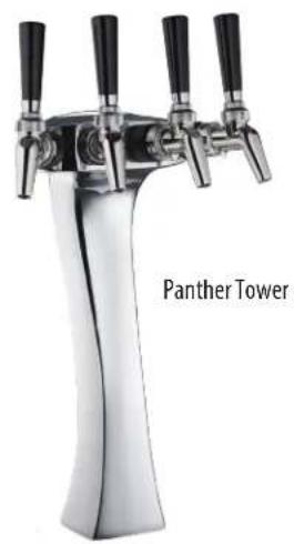
Close-up of a stainless steel double-tank showerhead with four black handles, labeled 'Panther Tower' (no other text or symbols visible)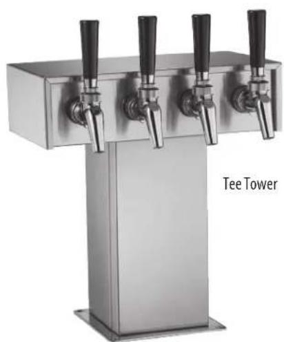
natural_image
Exterior view of a stainless steel multi-tvertical drain stand with four black handles, labeled 'Tee Tower' (no other text or symbols visible)Form No. Z2351
Rev. 11.2.22

DISPENSING TOWERS DRAFT ARMS, 2-6 FAUCET TEE TOWERS, LUCKY AND PANTHER TOWERS
TABLE OF CONTENTS
Beer and Wine Kits .... 3
Tools and Materials Required 3
Dispensing Kit Component Parts 3
Air Scoops for Field Retrofit Kits 7
General Installation and Field Retrofit Installation 8
Safety Information 8
About Wine Dispensing 8
Air Distributor and Air Scoop Installation - Field Retrofit Instructions 9
Air Tubing to Air Scoop Attachment 9
Air Distributor Assembly Attachment to Cabinet....9
Draft Arm and Tee Tower Instructions 10
Draft Arm Preparation 10
Tee Tower Preparation 10
Mounting Draft Arms or Tee Towers to a Cabinet Top 10
Mounting Draft Arms or Tee Towers to a Counter Top 11
Attaching Faucets to Draft Arms or Tee Towers 11
Mounting the Beer/Wine Drainer to a Cabinet Top 11
Mounting the Beer/Wine Drainer to a Counter Top 12
Running the Air Scoop Tubing to the Draft Arms or Tee Towers 12
Attaching the Beer Line to the Draft Arms or Tee Towers 13
Attaching the Wine Line to Draft Arms or Tee, Lucky or Panther Towers 13
Attaching the Gas Line Tubing 14
Attaching the Tapping Hole Covers 14
Attaching the Air Distributor Cover.... 14
Checking the System for Leaks 14
Lucky and Panther Tower Instructions 15
Lucky and Panther Tower Preparation 15
Mounting Lucky or Panther Towers to a Cabinet Top 15
Mounting Lucky or Panther Towers to a Counter Top 15
Attaching Faucets to Lucky or Panther Towers 15
Mounting the Beer/Wine Drainer to a Cabinet Top 16
Mounting the Beer/Wine Drainer to a Counter Top 17
Running the Air Scoop Tubing to the Lucky or Panther Towers 17
Attaching the Beer Line to the Lucky or Panther Towers 18
Attaching the Gas Line Tubing 18
Attaching the Tapping Hole Covers 18
Attaching the Air Distributor Cover 19
Checking the System for Leaks 19
Appendix 20

DISPENSING TOWERS DRAFT ARMS, 2-6 FAUCET TEE TOWERS, LUCKY AND PANTHER TOWERS
Please follow these instructions to ensure proper installation of Perlick beer and wine dispensing towers. These instructions cover 3" Draft Arms and Tee, Lucky and Panther Towers. These instructions apply to the following beer and wine dispensing kits:
Beer Kits
| 69526-1DA 69526-1 | DATF 69526-2DA 69526-2 | DATF 69526-3DA 69526-3 | DATF | ||
| 69526-2TT 69526-2 | TTTF 69526-3TT 69526-3T | TF 69526-4TT 69526-4TTTF | |||
| 69526-5TT 69526-5 | TTTF 69526-6TT 69526-6T | TF 69526-2N 69526-2NTF | |||
| 69526-1L 69526-1 | LG 69526-2L 69526-2LG 69 | 526-3P 69526-3PG | |||
| 67945-2DA 67945-2 | TT 67945-4TT 67945-2L |
Wine Kits
| 69526W-1DA 69526W-2DA 69526W-3DA 69526W-2TT 69526W-3TT | ||
| 69526W-4TT 69526W-5TT 69526W-1L 69526W-2L 69526W-3P | ||
| 67945W-2DA 67945W-2TT 67945W-4TT 67945W-2L |
For field installation, add a -R to the factory kit part number.
Note: Each kit contains enough hardware to install up to six product lines. Depending on how many lines you are installing, you may have parts left over after the installation is complete.
Tools and Materials Required
- Safety glasses
- Rubber gloves
- Utility knife or vinyl tubing cutter
- Slotted screwdriver
- 1/4" nut driver (optional)
- 6" or 8" adjustable wrench
- Cordless drill driver
- 5/16" socket head driver bit
Dispensing Kit Component Parts
- Draft Arm, Tee Tower, Lucky or Panther Tower
natural_image
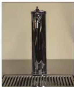
Close-up of a metallic cylindrical object with a textured top and side grating (no visible text or symbols)Draft Arm
Tee Tower

natural_image
Abstract black sculptural object resembling a stylized flame or torch, mounted on a pedestal (no text or symbols visible)Lucky (shown) or Panther Tower

DISPENSING TOWERS DRAFT ARMS, 2-6 FAUCET TEE TOWERS, LUCKY AND PANTHER TOWERS
Dispensing Kit Component Parts, Continued
natural_image
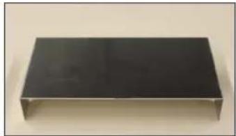
Black rectangular metal object on a plain background (no text or symbols visible)- Air Distributor Cover 68678-1

natural_image
Two black plastic electronic components on a plain surface (no text or symbols visible)- DZS36 Air Distributor Cover 68779-1
natural_image
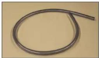
Coiled metal pipe or wire against a plain background (no text or symbols visible)- Gas/CO2 Tubing C23975-1

natural_image
Coiled black cable with metallic connectors, no visible text or symbols- Beer Line Connector 532
natural_image
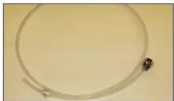
Close-up of a thin, flexible wire or cable with a small dark object attached at the end (no text or symbols visible)- Wine Line Connector 67750
natural_image
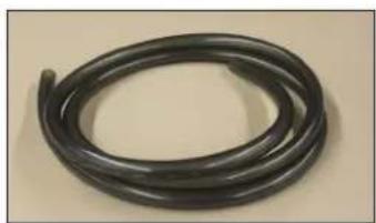
Coiled black plastic hose or tube against a plain background (no text or symbols visible)- Anti-Microbial Drain Tubing 1390D

DISPENSING TOWERS DRAFT ARMS, 2-6 FAUCET TEE TOWERS, LUCKY AND PANTHER TOWERS
Dispensing Kit Component Parts, Continued

natural_image
Exterior view of a brown rectangular device with a metallic cylindrical connector attached (no visible text or symbols)- 630SS – Forward Sealing Faucet, 304 Stainless Steel
natural_image
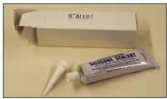
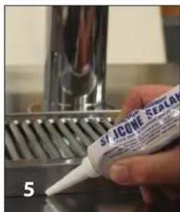
Product packaging and tube with a white plastic container (no visible text or symbols)- Silicone Sealant C15997
natural_image
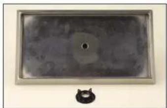
Rectangular metallic object with a central hole and a small circular inset, placed on a plain surface (no text or symbols visible)- Drain Pan C18640A
natural_image
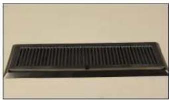
Black rectangular ventilation grille with horizontal ridges (no text or symbols visible)- DZS36 Drip Tray 68819

natural_image
Close-up of a plain white cylindrical object against a plain beige background (no text or symbols visible)- Waste Bottle - Wine C24392-1

natural_image
Metal mechanical bracket component (no text or symbols visible)- Waste Bottle Holder - Wine 68693-1

DISPENSING TOWERS DRAFT ARMS, 2-6 FAUCET TEE TOWERS, LUCKY AND PANTHER TOWERS
Dispensing Kit Component Parts, Continued

natural_image
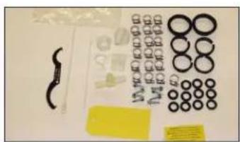
Assorted mechanical parts including bolts, rings, and clamps arranged on a plain surface (no text or symbols visible)- Tapping Parts Kit 67305
natural_image
Collection of small mechanical parts and circular components laid out on a white surface (no text or symbols visible)- Tapping Parts Kit - Wine 67305W

natural_image
White cylindrical pipe lying flat on a plain yellow background (no text or symbols visible)- PVC Pipe 67562
natural_image
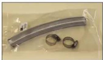
Metallic curved object with two metal rings, wrapped in plastic wrap (no text or symbols visible)- Parts Bag 67835

natural_image
Mechanical valve component with black and metallic parts (no visible text or symbols)- Keg Coupler, 304 Stainless Steel - 36000SS

natural_image
Two black L-shaped objects with small holes, placed side by side on a beige background (no text or symbols)- Tapping Cover 67852-1
natural_image
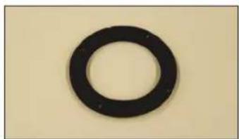
Simple black ring on a beige background (no text or symbols)- Gasket 57355-1

DISPENSING TOWERS DRAFT ARMS, 2-6 FAUCET TEE TOWERS, LUCKY AND PANTHER TOWERS
Air Scoops for Field Retrofit Kits (-R) only - see page 9.
natural_image
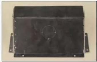
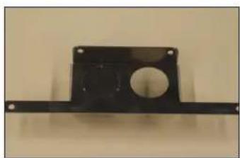
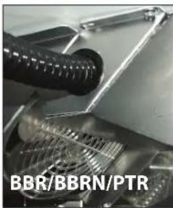
Exterior view of a black rectangular electronic component with mounting flanges (no visible text or symbols)- Air Scoop 69315-1 For BBR/BBRN/PTR
natural_image
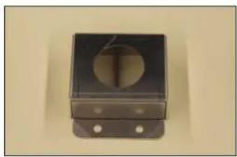
Black square metal bracket with circular cutout and mounting holes (no text or symbols visible)- Air Scoop 68686-2 For DZS60
natural_image
Metal bracket with circular cutout and mounting holes (no text or symbols visible)- Air Scoop 68778-1 For PTS
natural_image
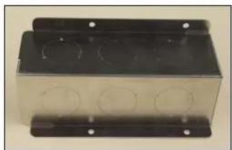
Exterior view of a rectangular metal enclosure with three circular cutouts on its side (no text or symbols visible)- Air Scoop 68685-1 For BBS/BBSN

DISPENSING TOWERS DRAFT ARMS, 2-6 FAUCET TEE TOWERS, LUCKY AND PANTHER TOWERS
General Installation and Field Retrofit Installation
Cabinets ordered with a dispensing kit from the factory will already have the air distributor and air scoop installed. If you are doing a field retrofit on a previously installed cabinet, your kit also will include an air distributor and an air scoop. Please refer to the Air Distributor and Air Scoop Installation - Field Retrofit Instructions section on the following page to install these components. Note that field retrofit kits will have a "-R" at the end of the kit model number.
Beer/Wine System Safety

WARNING - Any compressed gas such as CO2 can be dangerous! It is important that reputable companies are used to supply and install systems and to thoroughly train all staff who will use the system.
NEVER Connect a pressurized gas cylinder unless there are at least two safety mechanisms in the pressure system. At least one at the regulator and one at the product container coupler.
NEVER Connect a pressurized gas cylinder directly to a keg.
NEVER Connect your own equipment to the pressure system.
ALWAYS Report any damage or leaks and have them repaired immediately.
ALWAYS Store gas cylinders in the upright position.
ALWAYS Ventilate after a gas leak.
ALWAYS Keep gas cylinders away from heat and preferably stored in a cooler part of the establishment.
ALWAYS Thoroughly train all staff who use the equipment.
About Wine Dispensing
Perlick offers the industry's most complete line of commercial refrigerated wine storage and serving equipment. Perlick's WINEcertified family of products, specified in the Dispensing Kit Component Parts section of this document, are manufactured specifically to properly store and dispense wine.
Wine components include a sanitary 304 stainless steel faucet, shank, union and keg coupler with a sanitary 304 stainless steel probe, as well as flavor-lock tubing, all to protect the delicate flavors of wines.

To preserve the integrity of Perlick WINEcertified wine products and systems, DO NOT use beer kit components in wine systems.

WARNING: California Prop 65 Notice
These products may expose you to chemicals including Chromium, which are known to the state of California to cause cancer and birth defects or other reproductive harm. For more information on whether a product in this list contains these chemicals, please refer to the specific product page at perlick.com. Or to find out more about Prop 65, go to P65Warnings.ca.gov.

DISPENSING TOWERS DRAFT ARMS, 2-6 FAUCET TEE TOWERS, LUCKY AND PANTHER TOWERS
AIR DISTRIBUTOR AND AIR SCOOP INSTALLATION - FIELD RETROFIT INSTRUCTIONS
Air Tubing to Air Scoop Attachment
natural_image
Close-up of a white electronic device with a black circular button and two circular holes, labeled '22 22' at the bottom (no other text or symbols visible)
natural_image
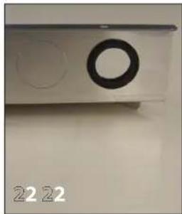
Metallic mechanical component with two circular holes and a black ring, placed on a plain surface (no text or symbols visible)- Select the appropriate air scoop for the cabinet model being retrofitted. Air scoop photos with the cabinet models they apply to are shown on page 7.
- Knock out the desired slug from the air scoop and insert the 1" snap bushing.

natural_image
Close-up of a black mechanical component with a red arrow pointing to a glossy surface (no visible text or symbols)
natural_image
Close-up of a mechanical component with a red arrow pointing to a circular feature, no visible text or symbols.- Secure the air tube in place by attaching a cable tie on each side of the snap ring.
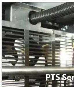
- Mount the air scoop assembly against the air discharge plenum of the evaporator.
- Please refer to Diagram 5 in the Appendix for a drawing of the air scoop used on the BBS, BBSN, and PTS Models.
natural_image
Industrial equipment setup with a threaded bolt and metal frame, no visible text or symbols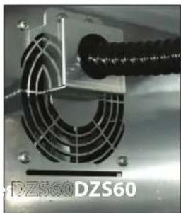
natural_image
Close-up of a mechanical fan or vent with a coiled cable, no visible text or symbols on the fan or background.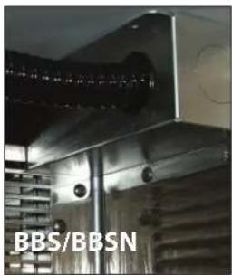
Air Distributor Assembly Attachment to Cabinet
natural_image
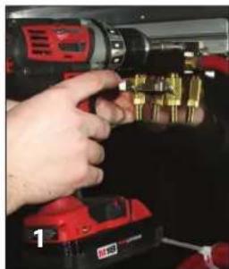
Close-up of hands using a red drill bit to adjust or install a component, no visible text or symbols
natural_image
Close-up of a metallic electrical connector with brass connectors and a red cable, mounted on a metal frame (no visible text or symbols)- Place the air distributor cover bracket behind the air distributor assembly and mount it to the desired location on the cabinet wall. (Two-line assembly shown.)

DISPENSING TOWERS DRAFT ARMS, 2-6 FAUCET TEE TOWERS, LUCKY AND PANTHER TOWERS
DRAFT ARM AND TEE TOWER INSTRUCTIONS
Draft Arm Preparation

natural_image
Close-up of a metallic cylindrical object with a small protrusion, placed on a surface with a mesh base (no visible text or symbols)Remove backing from foam gasket #57355-1. Attach the gasket to the bottom flange of the draft arm, ensuring the four mounting holes are aligned.
Tee Tower Preparation
There is no preparation needed for Tee Tower style dispensing heads.
Mounting Draft Arms or Tee Towers to a Cabinet Top
Note: If you are mounting the tower to a counter top instead of the cabinet top, please refer to the section titled Mounting Draft Arms or Tee Towers to a Counter Top on the following page.
natural_image
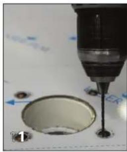
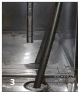
Close-up of a precision drill bit dispensing liquid into a circular tank (no visible text or symbols)-
Most cabinets come with pre-drilled hole configurations in the cabinet top for mounting dispensing towers and drainers. However, if the holes need to be drilled during field installation, templates are available at www.perlick.com/bar-beverage-equipment/specifications-downloads/tower-and-drip-pan-templates/.
-
Factory-provided tapping holes will have a wood block embedded in the cabinet top for additional support. It is recommended that you drill 3/32" pilot holes into the wood block for the four mounting holes on the tower flange. Remove the protective film paper from the area where the tower will be installed.
natural_image
Close-up of a hand using a tool to press or install a metallic cylindrical component (no visible text or symbols)- Attach the dispensing tower to the cabinet top using a flathead screwdriver. To prevent accidental scratches or gouges, cover the tower flange and cabinet top while mounting the tower. The tower should be sealed to the cabinet top with a food grade RTV silicone.
Mounting Draft Arms or Tee Towers to a Counter Top
- A PVC tube, (Part #67562), is included in the tapping kit. This will be used as an air shaft when mounting to a counter top. Please refer to Diagram 7 in the Appendix for detail on how to mount a Draft Arm or Tee Tower to a counter top. The tower should be sealed to the cabinet top with a food grade RTV silicone.

DISPENSING TOWERS DRAFT ARMS, 2-6 FAUCET TEE TOWERS, LUCKY AND PANTHER TOWERS
DRAFT ARM AND TEE TOWER INSTRUCTIONS, Continued
Attaching Faucets to Draft Arms or Tee Towers
natural_image
Close-up of a hand holding a metallic mechanical component, no visible text or symbols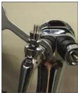
natural_image
Close-up of a metallic mechanical component with threaded joints and a curved handle (no visible text or symbols)- Align splines on faucet to nut on faucet head. Orient faucet so it is perpendicular to the cabinet top. Hand tighten.
- Using the spanner wrench provided, snug faucet tight. Do not over-tighten.
Mounting the Beer/Wine Drainer to a Cabinet Top
Note: If you are mounting the drainer to a counter top instead of the cabinet top please refer to the section titled Mounting the Beer/Wine Drainer to a Counter Top.

natural_image
Close-up of a hand holding a metallic object with a yellow tip, mounted on a metal shelf (no visible text or symbols)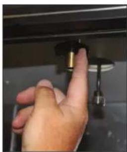
natural_image
Close-up of a hand pressing a button on a metal panel (no visible text or symbols)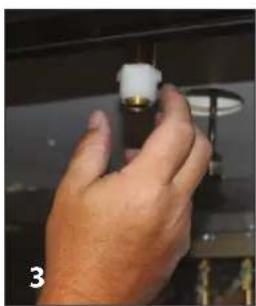
natural_image
Close-up of a hand holding a small white component with a brass shaft, against a dark background (no visible text or symbols)- Slide the threaded drainer nipple through cabinet top hole. On the underside of the cabinet top, tighten the drainer using the plastic nut. Take caution not to over-tighten.
- Attach the nylon reducing bushing to the drainer until hand tight.
- Attach the nylon elbow to the reducing bushing.
natural_image
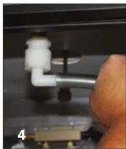
Close-up of a hand adjusting a white pipe fitting with a black circular component (no visible text or symbols)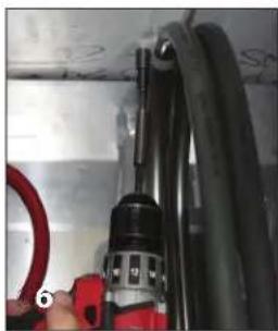
natural_image
Close-up of a red-handled tool holding a black cylindrical device against a white wall, with no visible text or symbols.- Slide the 1/2" ID anti-microbial drain tubing over the barbed end of the nylon elbow.
- Use the nylon hose clips and self-drilling screws to secure the drain tubing to the cabinet walls. Ensure the tubing will be out of the way of loading and unloading kegs.
- Route the anti-microbial tubing to the beer/wine collection drain or waste container. It may be routed to the floor drain located in the right rear corner of the cabinet. The cabinet floor drain must then be plumbed to an external drain. There are also knockouts provided on
the cabinet ends as other options for exiting the cabinet.
natural_image
Close-up of a white plastic bottle with a metal rod inserted, surrounded by cylindrical containers (no visible text or symbols)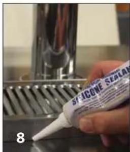
- Wine dispensing kits also include a polyethylene waste bottle as an optional method to collect wine waste. The waste bottle holder is hung over the rim of a keg and the waste bottle is snapped into the holder.
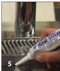
- Apply a bead of silicone around the perimeter of the drainer.

DISPENSING TOWERS DRAFT ARMS, 2-6 FAUCET TEE TOWERS, LUCKY AND PANTHER TOWERS
DRAFT ARM AND TEE TOWER INSTRUCTIONS, Continued
Mounting the Beer/Wine Drainer to a Counter Top
Note: If you are mounting the drainer to the cabinet top instead of a counter top, please refer to the section titled Mounting the Beer/Wine Drainer to a Cabinet Top.

natural_image
Close-up of a metallic tool with a brass fitting, attached to a mechanical component (no visible text or symbols)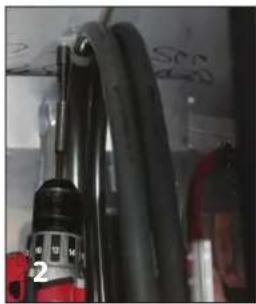
natural_image
Close-up of a black and red industrial pipe with coiled cable, no visible text or symbols- Slide the 1/2" ID anti-microbial drain tubing over the end of drainer nipple. Feed the drain tubing through the drainer hole of the counter top and the cabinet top.
- Use the nylon hose clips and self-drilling screws to secure the drain tubing to the cabinet walls. Ensure the tubing will be out of the way of loading and unloading kegs.
natural_image
Close-up of a metallic industrial pipe with a black rod inserted into a circular opening, no visible text or symbols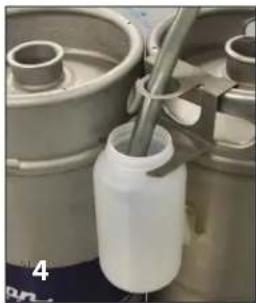
natural_image
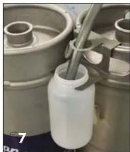
Close-up of a white plastic bottle with a metal rod inserted, surrounded by mechanical components (no visible text or symbols)-
Route the anti-microbial tubing to the beer/wine collection drain or waste container. It may be routed to the floor drain located in the right rear corner of the cabinet. It must then be plumbed to an external drain. There are also knockouts provided on the cabinet ends as other options for exiting the cabinet.
-
Wine dispensing kits also include a polyethylene waste bottle as an optional method to collect wine waste. The waste bottle holder is hung over the rim of a keg and the waste bottle is snapped into the holder.
- Apply a bead of silicone around the perimeter of the drainer. This will provide a seal as well as hold it in position.
Running the Air Scoop Tubing to the Draft Arms or Tee Towers
natural_image
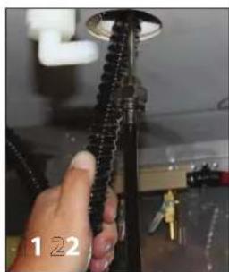
Close-up of a hand holding a black threaded metal component with a circular top fixture (no visible text or symbols)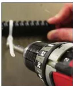
natural_image
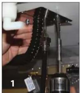
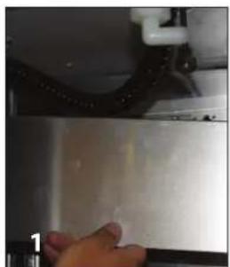
Close-up of a hand using a drill bit on a red and black tool (no visible text or symbols)- Trim the black corrugated tubing from the air scoop so the tube is inserted approximately halfway into the dispensing head.
- Use the mountable cable tie and a self-drilling screw to hold the black air tube out of the way of keg loading and unloading.

DISPENSING TOWERS DRAFT ARMS, 2-6 FAUCET TEE TOWERS, LUCKY AND PANTHER TOWERS
DRAFT ARM AND TEE TOWER INSTRUCTIONS, Continued
Attaching the Beer Line to the Draft Arms or Tee Towers

natural_image
Close-up of hands holding a small metallic connector with a black ring (no visible text or symbols)
natural_image
Close-up of a hand holding a metal pipe fitting with a circular valve, no visible text or symbols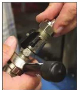
natural_image
Close-up of hands holding a mechanical clamp or connector (no visible text or symbols)- Insert rubber washer into end of beer line connector and attach to the beer fitting on the Draft Arm tower. Tighten with an adjustable wrench but do not over-tighten.
- Insert rubber washer into the other end of the beer line and attach to keg coupler. Tighten with an adjustable wrench but do not over-tighten.
- Repeat for each additional supply tubes.
Attaching the Wine Line to Draft Arms or Tee, Lucky or Panther Towers
natural_image
Close-up of hands connecting a mechanical component with two yellow connectors (no visible text or symbols)
natural_image
Close-up of hands holding a small metallic object, possibly a key or lock, with no visible text or symbols.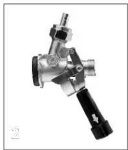
natural_image
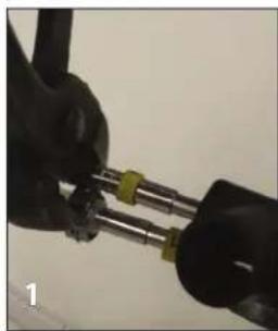
Mechanical valve component with metallic and black fittings (no visible text or symbols)- Push the flavor lock barrier tubing over the barbed connection on the wine tower and secure it with a clench style clamp.
- Insert a rubber washer into the other end of the flavor lock barrier tubing and attach it to the keg coupler. Tighten with an adjustable wrench, but do not over-tighten.
Note: Keg couplers are constructed of 304 stainless steel to protect the flavor of beverages.
- Repeat for each additional supply tube.

DISPENSING TOWERS DRAFT ARMS, 2-6 FAUCET TEE TOWERS, LUCKY AND PANTHER TOWERS
DRAFT ARM AND TEE TOWER INSTRUCTIONS, Continued
Attaching the Gas Line Tubing
natural_image
Close-up of a hand using a tool to adjust or install a metal component, with no visible text or symbols.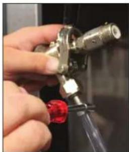
natural_image
Close-up of a hand holding a metallic connector with a red tag, no visible text or symbols- Attach one end of gas line to a valve on the air distributor manifold and tighten with a hose clamp, using a 1/4" nut driver.
- Repeat for each additional product line.
- Attach the other end of the gas line to the keg coupler and tighten with a hose clamp, using a 1/4" nut driver.
Attaching the Tapping Hole Covers
natural_image
Close-up of a hand holding a black mechanical component with a white pipe, no visible text or symbols- To comply with NSF standards, please attach the tapping hole covers provided.
- The two piece cover can be adjusted to tighten snugly around beer lines and air scoop tubing.
- Position covers tightly around tubing and mount to the bottom side of the cabinet top using a cordless drill with a 5/16" socket head bit and the self-drilling screws provided. Please refer to Diagram 3 in the Appendix.
Attaching the Air Distributor Cover
natural_image
Close-up of a hand pressing down on a metallic surface with a curved pipe and valve (no visible text or symbols)- To comply with NSF standards, the air distributor cover should be installed. It easily can be removed to access the valves on the air distributor.
- Each end of the cover has a knockout to provide clearance for the gas line. Remove the appropriate knockout.
- Route the gas line through the side of the cover and hang the cover on the air distributor bracket. Please refer to Diagram 4 in the Appendix.
Checking the System for Leaks
- It is important to ensure the entire system is leak free.
- The system can be checked by doing a pressure decay test or by tapping the system and inspecting for product leaks and checking for gas leaks with soap and bubbles. Repair any leaks immediately.

DISPENSING TOWERS DRAFT ARMS, 2-6 FAUCET TEE TOWERS, LUCKY AND PANTHER TOWERS
LUCKY AND PANTHER TOWER INSTRUCTIONS
Lucky and Panther Tower Preparation

natural_image
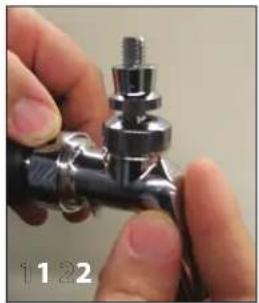
Black sculpted object resembling a stylized torch or trophy, mounted on a pedestal (no text or symbols visible)- Cut the plastic cable tie and remove the hose clamp.
- Remove the plastic jam nut, mounting nut, flat washer, and second jam nut. Do not remove the rubber flange gasket.
Mounting Lucky or Panther Towers to a Cabinet Top
Note: If you are mounting the tower to a counter top instead of the cabinet top please refer to the section titled Mounting Towers Lucky or Panther Towers to a Counter Top.

natural_image
Close-up of a hand holding a mechanical device with a black cylindrical component and metallic base (no visible text or symbols)
natural_image
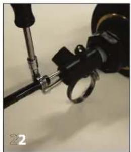
Hand holding a black mechanical component with a metallic screw, against a blurred background (no visible text or symbols)- Most cabinets come with pre-drilled hole configurations in the cabinet top for mounting dispense towers and drainers. However, if the holes need to be drilled during field installation, templates are available at http://www.perlick.com/bar-beverage-equipment/specifications-downloads/tower-and-drip-pan-templates/.
- Insert the threaded mounting shaft through the hole in the cabinet top. On the underside of the cabinet top place large flat washer over threaded shaft and tighten tower down using plastic nut. Take caution not to over-tighten nut. You will not use either of the jam nuts for the installation. The tower should be sealed to the cabinet top with a food grade RTV silicone.
Mounting Lucky or Panther Towers to the Counter Top
- Please refer to Diagram 8 in the Appendix for a detailed drawing on how to mount Lucky or Panther towers to a counter top. The tower should be sealed to the counter top with a food grade RTV silicone.
Attaching Faucets to Lucky or Panther Towers

natural_image
Close-up of a hand holding a metallic pipe fitting with a screw, no visible text or symbols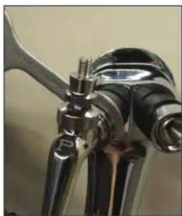
natural_image
Close-up of a metallic mechanical tool or connector with no visible text or symbols- Align splines on faucet to nut on faucet head. Orient faucet so it is perpendicular to the cabinet top. Hand tighten.
- Using the spanner wrench provided, snug faucet tight. Do not over-tighten.

DISPENSING TOWERS DRAFT ARMS, 2-6 FAUCET TEE TOWERS, LUCKY AND PANTHER TOWERS
LUCKY AND PANTHER TOWER INSTRUCTIONS, Continued
Mounting the Beer/Wine Drainer to a Cabinet Top
Note: If you are mounting the drainer to a counter top instead of the cabinet top, please refer to the section titled Mounting the Beer/Wine Drainer to a Counter Top.

natural_image
Close-up of a hand holding a metallic tool above a metal shelf, no visible text or symbols
natural_image
Close-up of a hand pressing a button on a metal fixture (no visible text or symbols)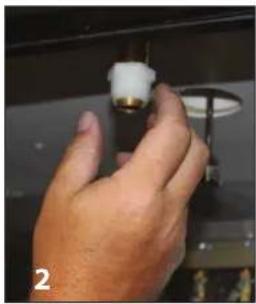
natural_image
Close-up of a hand holding a small white object with a brass handle, against a dark background (no visible text or symbols)- Slide the threaded drainer nipple through the cabinet top hole. On the underside of the cabinet top, tighten down the drainer using the plastic nut. Take caution not to over-tighten.
- Attach the nylon reducing bushing to the drainer until hand tight.
natural_image
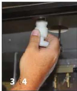
Close-up of a hand holding a white PVC plug attached to a black fixture (no text or symbols visible)
natural_image
Close-up of a hand adjusting a white pipe fitting on a dark surface (no visible text or symbols)-
Attach the nylon elbow to the reducing bushing.
-
Slide the 1/2" ID anti-microbial drain tubing over the barbed end of the nylon elbow.
natural_image
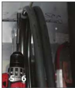
Close-up of a black cable with a red component, no visible text or symbols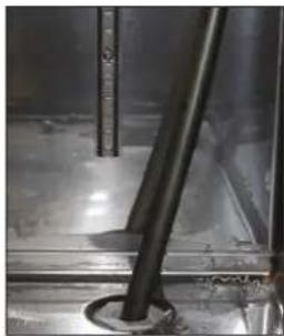
natural_image
Close-up of a mechanical pipe or tube inserted into a concrete block, no visible text or symbols- Use the nylon hose clips and self-drilling screws to secure the drain tubing to the cabinet walls. Ensure the tubing will be out of the way of loading and unloading kegs.
-
Route the anti-microbial tubing to the beer/wine collection drain or waste container. It may be routed to the floor drain located in the right rear corner of the cabinet. The cabinet floor drain must then be plumbed to an external drain. There are also knockouts provided on the cabinet ends as other options for exiting the cabinet.
-
Wine dispensing kits also include a polyethylene waste bottle as an optional method to collect wine waste. The waste bottle holder is hung over the rim of a keg and the waste bottle is snapped into the holder.
- Apply a bead of silicone around the perimeter of the drainer.

natural_image
Close-up of a white plastic bottle with a metal rod inserted, surrounded by metallic cylindrical components (no visible text or symbols)

DISPENSING TOWERS DRAFT ARMS, 2-6 FAUCET TEE TOWERS, LUCKY AND PANTHER TOWERS
LUCKY AND PANTHER TOWER INSTRUCTIONS, Continued
Mounting the Beer/Wine Drainer to a Counter Top
natural_image
Close-up of a metallic and brass-colored pipe fitting with a label 'L-1' visible (no readable text or symbols on the object itself)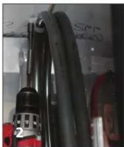
natural_image
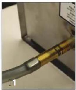
Close-up of a mechanical device with black cables and a red component, no visible text or symbols- Slide the 1/2" ID anti-microbial drain tubing over end of drainer nipple. Feed the drain tubing through the drainer hole of the counter top and the cabinet top. (The hose may be soaked in hot water prior to doing this to make it more flexible and better fit around the drain pipe.)
- Use the nylon hose clips and self-drilling screws to secure the drain tubing to the cabinet walls. Ensure the tubing will be out of the way of loading and unloading kegs.
natural_image
Close-up of a metal pipe with a black cylindrical component inserted, no visible text or symbols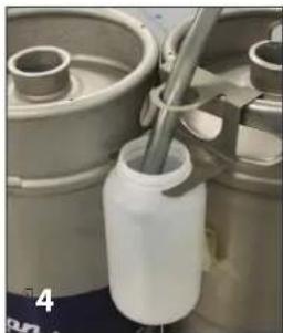
natural_image
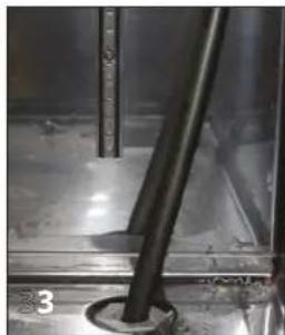
Close-up of a white plastic bottle with a metal rod inserted, surrounded by mechanical components (no visible text or symbols)- Route the anti-microbial tubing to the beer/wine collection drain or waste container. It may be routed to the floor drain located in the right rear corner of the cabinet. It must then be plumbed to an external drain. There are also knockouts provided on the cabinet ends as other options for exiting the cabinet.
- Wine dispensing kits also include a polyethylene waste bottle as an optional method to collect wine waste. The waste bottle holder is hung over the rim of a keg and the waste bottle is snapped into the holder.
- Apply a bead of silicone around the perimeter of the drainer. This will provide a seal as well as hold it in position.
Running the Air Scoop Tubing to the Lucky or Panther Towers
natural_image
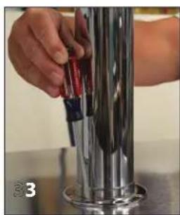
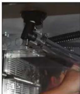
Close-up of a hand using a tool to adjust or install a mechanical component (no visible text or symbols)- You will need parts bag #67835 to attach the black corrugated air tubing to the air-cooled fitting on the Lucky or Panther towers.
- Insert the black corrugated air tubing into the 1-1/8" ID vinyl tubing and tighten with the hose clamp.
- Attach the other end of the 1-1/8" vinyl tube to the air-cooled fitting on the Lucky or Panther tower and tighten with a hose clamp. Refer to Diagram 6 in the Appendix.

DISPENSING TOWERS DRAFT ARMS, 2-6 FAUCET TEE TOWERS, LUCKY AND PANTHER TOWERS
LUCKY AND PANTHER TOWER INSTRUCTIONS, Continued Attaching the Beer Line to the Lucky or Panther Towers

natural_image
Close-up of a hand using a power tool to cut a black cable with a metallic connector (no text or symbols visible)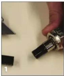
natural_image
Close-up of a hand holding a black mechanical component, with small black blocks nearby (no visible text or symbols)
natural_image
Close-up of a mechanical tool with a black component and metallic ring (no visible text or symbols)- On one end of the beer connector, cut off the beer nut fitting.
- Push the beer line connector end over the barbed end of the product supply line and tighten with a clamp using a 1/4" nut driver or slotted screwdriver.
natural_image
Close-up of a mechanical clamp or connector with metal fittings and a black handle, no visible text or symbols
natural_image
Close-up of hands holding a small mechanical component with a ring, no visible text or symbols
natural_image
Close-up of hands holding a metallic mechanical component with a black handle (no visible text or symbols)- Insert the rubber washer into the other end of the beer line and attach to the keg coupler. Tighten with an adjustable wrench but do not over-tighten.
- Repeat for each additional supply tube.
Attaching the Gas Line Tubing

natural_image
Close-up of a hand using a tool to adjust or install electronic components, with a vertical scale bar on the right (no visible text or symbols)
natural_image
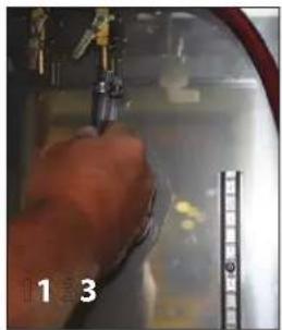
Close-up of a hand holding a metallic valve with a red handle, no visible text or symbols- Attach one end of the gas line to a valve on the air distributor manifold and tighten with a hose clamp.
- Repeat for each additional product line.
- Attach the other end of the gas line to the keg coupler and tighten with a hose clamp.
Attaching the Tapping Hole Covers
natural_image
Close-up of a hand holding a mechanical component with a metallic bracket and a small cylindrical part (no visible text or symbols)- To comply with NSF standards, please attach the tapping hole covers provided.
- The two-piece cover can be adjusted to tighten snugly around beer lines and air scoop tubing.
- Position the covers tightly around the tubing and mount to the bottom side of the cabinet top using a cordless drill with a 5/16" socket head bit and the self-drilling screws provided. Please refer to Diagram 7 in the Appendix.

DISPENSING TOWERS DRAFT ARMS, 2-6 FAUCET TEE TOWERS, LUCKY AND PANTHER TOWERS
LUCKY AND PANTHER TOWER INSTRUCTIONS, Continued
Attaching the Air Distributor Cover

natural_image
Close-up of a hand pressing down on a metal panel with a curved pipe and handle (no visible text or symbols)- To comply with NSF standards, the air distributor cover should be installed. It can be easily removed to access the valves on the air distributor.
- Each end of the cover has a knockout to provide clearance for the gas line. Remove the appropriate knockout.
- Route the gas line through the side of the cover and hang the cover on the air distributor bracket.
Checking the System for Leaks
- It is important to ensure the entire system is leak free.
- The system can be checked by doing a pressure decay test or by tapping the system and inspecting for product leaks and checking for gas leaks with soap and bubbles. Repair any leaks immediately.

DISPENSING TOWERS DRAFT ARMS, 2-6 FAUCET TEE TOWERS, LUCKY AND PANTHER TOWERS
APPENDIX - DIAGRAM 1
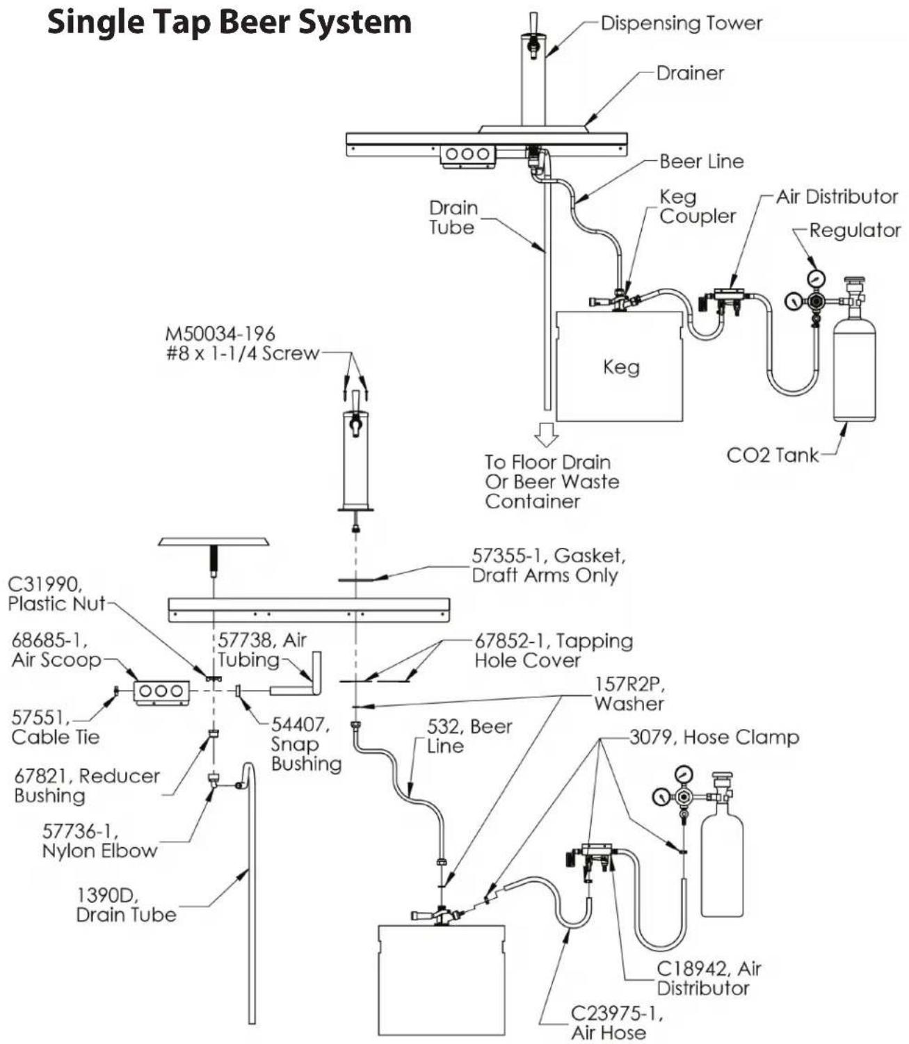

DISPENSING TOWERS DRAFT ARMS, 2-6 FAUCET TEE TOWERS, LUCKY AND PANTHER TOWERS
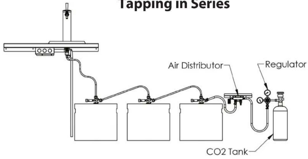
APPENDIX - DIAGRAM 2
Tapping in Series

flowchart
graph TD
    A["3rd KEG"] --> B["157R2P, Washer"]
    C["2nd KEG"] --> D["1st KEG"]
    E["532, Beer Line"] --> F["DO NOT remove rubber check valve, Part # 23682-2P, from coupler on 1st keg."]
    G["Remove rubber check valve, Part # 23682-2P, from coupler on 2nd & 3rd kegs before installing beer line, Part # 532."] --> H["Final device"]
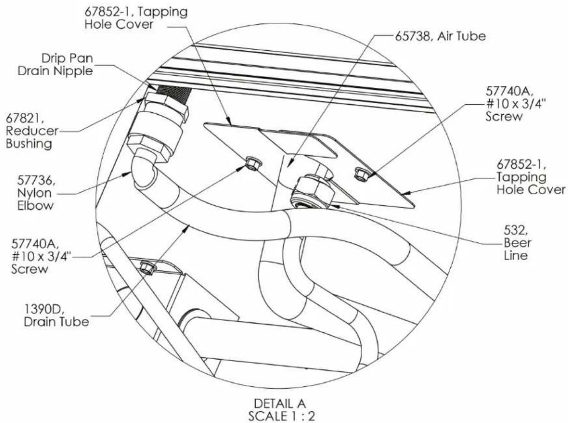
APPENDIX - DIAGRAM 3
Drip Pan Drain Connection and Tapping Hole Cover Installation
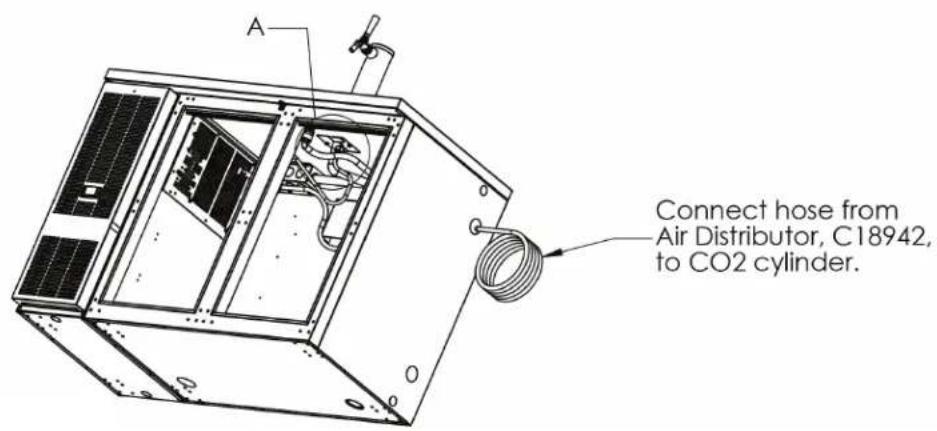
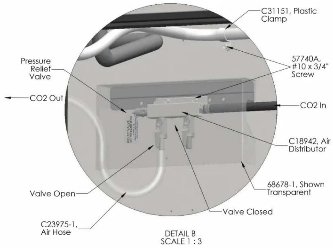
APPENDIX - DIAGRAM 4
Air Distributor Connections and Excess Drip Pan Drain Tube Mounting
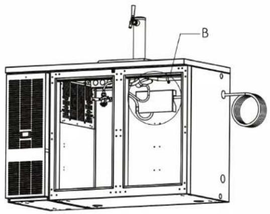
natural_image
Technical line drawing of an industrial machine with labeled component B (no text or symbols beyond label)APPENDIX - DIAGRAM 5
Air Scoop Installation

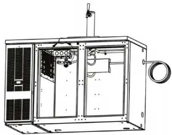
natural_image
Technical line drawing of an industrial machine with internal components and mounting bracket (no text or symbols)APPENDIX - DIAGRAM 6
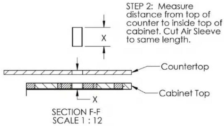
Air Sleeve Installation through Countertop and Back Bar Cabinet


DISPENSING TOWERS DRAFT ARMS, 2-6 FAUCET TEE TOWERS, LUCKY AND PANTHER TOWERS
APPENDIX - DIAGRAM 7
Air Connection
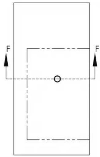
STEP 1: Position cabinet under counter in final position. Use existing 2-1/2" hole in counter to mark and drill 2-1/2" hole in cabinet top.

STEP 3: With Air Sleeve flush with top of counter temporarily hold in place with tape.
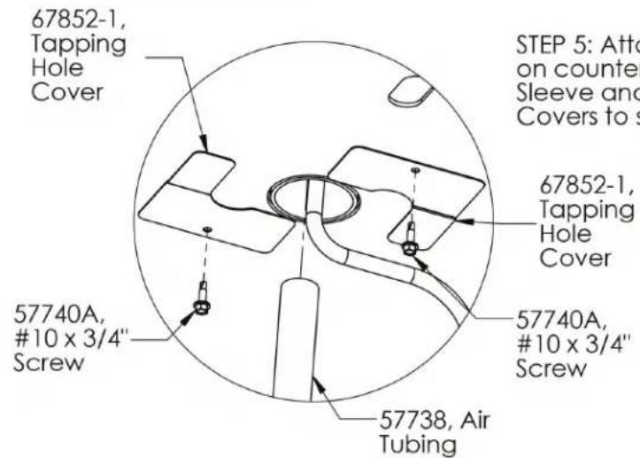
STEP 5: Attach Beer Line to Draft Arm and install on countertop. Insert Air Tube through Air Sleeve and into Draft Arm. Install the 2 Hole Covers to seal off hole using #10 x 3/4 Screws.

natural_image
Pure technical diagram of a mechanical assembly inside a circle (no text or symbols)APPENDIX - DIAGRAM 8
Lucky and Panther Tower
Mounting Reference


Form No. Z2351
Rev. 11.2.22
- Draft Arm, Lucky, Panther or Tee Towers
- DISPENSING TOWERS DRAFT ARMS, 2-6 FAUCET TEE TOWERS, LUCKY AND PANTHER TOWERS
- TABLE OF CONTENTS
- Tools and Materials Required
- Dispensing Kit Component Parts
- Dispensing Kit Component Parts, Continued
- Air Scoops for Field Retrofit Kits (-R) only - see page 9.
- General Installation and Field Retrofit Installation
- Beer/Wine System Safety
- About Wine Dispensing
- WARNING: California Prop 65 Notice
- AIR DISTRIBUTOR AND AIR SCOOP INSTALLATION - FIELD RETROFIT INSTRUCTIONS
- Air Tubing to Air Scoop Attachment
- Air Distributor Assembly Attachment to Cabinet
- DRAFT ARM AND TEE TOWER INSTRUCTIONS
- Draft Arm Preparation
- Tee Tower Preparation
- Mounting Draft Arms or Tee Towers to a Cabinet Top
- Mounting Draft Arms or Tee Towers to a Counter Top
- DRAFT ARM AND TEE TOWER INSTRUCTIONS, Continued
- Attaching Faucets to Draft Arms or Tee Towers
- Mounting the Beer/Wine Drainer to a Cabinet Top
- Mounting the Beer/Wine Drainer to a Counter Top
- Running the Air Scoop Tubing to the Draft Arms or Tee Towers
- Attaching the Beer Line to the Draft Arms or Tee Towers
- Attaching the Wine Line to Draft Arms or Tee, Lucky or Panther Towers
- Attaching the Gas Line Tubing
- Attaching the Tapping Hole Covers
- Attaching the Air Distributor Cover
- Checking the System for Leaks
- LUCKY AND PANTHER TOWER INSTRUCTIONS
- Lucky and Panther Tower Preparation
- Mounting Lucky or Panther Towers to a Cabinet Top
- Mounting Lucky or Panther Towers to the Counter Top
- Attaching Faucets to Lucky or Panther Towers
- LUCKY AND PANTHER TOWER INSTRUCTIONS, Continued
- Running the Air Scoop Tubing to the Lucky or Panther Towers
- LUCKY AND PANTHER TOWER INSTRUCTIONS, Continued Attaching the Beer Line to the Lucky or Panther Towers
- APPENDIX - DIAGRAM 2
- APPENDIX - DIAGRAM 3
- APPENDIX - DIAGRAM 4
- APPENDIX - DIAGRAM 5
- APPENDIX - DIAGRAM 6
- Air Sleeve Installation through Countertop and Back Bar Cabinet
- APPENDIX - DIAGRAM 7
- APPENDIX - DIAGRAM 8
Brand : Perlick
Model : 69526-3P
Category : Beer Pump