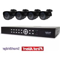
DCA8405-520 - Security Camera FIRST ALERT - Free user manual and instructions
Find the device manual for free DCA8405-520 FIRST ALERT in PDF.


| Product Type | Security Camera |
| Brand | First Alert |
| Model | DCA8405-520 |
| Dimensions | Approx. 3.2 x 2.8 x 2.2 inches |
| Weight | Approx. 0.5 lbs |
| Power Source | AC adapter or PoE (Power over Ethernet) |
| Video Resolution | 1080p Full HD |
| Field of View | 130° wide angle |
| Night Vision | Infrared LEDs up to 30 ft |
| Connectivity | Wi-Fi 802.11 b/g/n (2.4 GHz) or Ethernet |
| Motion Detection | Yes, with push notifications |
| Storage | MicroSD card slot (up to 128GB) or cloud subscription |
| Audio | Two-way audio with built-in microphone and speaker |
| Weather Resistance | IP65 weatherproof rating |
| Installation | Wall mount included, easy DIY setup |
| App Companion | First Alert app for iOS and Android |
| Warranty | 1 year limited warranty |
Frequently Asked Questions - DCA8405-520 FIRST ALERT
User questions about DCA8405-520 FIRST ALERT
0 question about this device. Answer the ones you know or ask your own.
Ask a new question about this device
Download the instructions for your Security Camera in PDF format for free! Find your manual DCA8405-520 - FIRST ALERT and take your electronic device back in hand. On this page are published all the documents necessary for the use of your device. DCA8405-520 by FIRST ALERT.
USER MANUAL DCA8405-520 FIRST ALERT
Thank you for choosing First Alert for your security needs!
For more than half a century, First Alert has made the home-safety and security products that make your job easier. Our products are built to the highest standard which has earned us a leadership role in the home-safety and security product categories. We are committed to serving our customers, from the professionals who install our products, to the families and businesses who count on them. First Alert has been helping families and businesses stay safe for over 50 years. By having a First Alert Security System, you're taking the first step in protecting your home or business from damage or theft. We're watching, even when you're not.
This manual is written for the SmartBridge™ DVRA0405/DVRA0805/DVRA0810/DVRA1610 DVRs. It was accurate at the time it was completed. However, because of our ongoing effort to constantly improve our products, additional features and functions may have been added since that time and on-screen displays may change. We encourage you to visit our website at www.firstalert.com to check for the latest manuals (English and Spanish), firmware updates, downloads, other security camera products and announcements. You'll find this product line under Home Security >> Security Cameras >>Wired Cameras.
INTRODUCTION
KEY PRODUCT FEATURES
Main Description
Eight channel H.264 digital video recorder with Internet remote surveillance, motion detection, PTZ and alarm control suitable for applications such as high-end residential - new or remodel, light commercial, small business/retail, small warehouse or small grocery.
Product Features
• Auto IP connection capability
• H.264 Compression & Virus free Linux O/S
• Record, playback, mobile phone live view, backup, control, & remote access
• 500 GB or 1 TB SATA hard drive installed
• Supports smart phone live view
- User-friendly interface: DVR capable of providing 16 bit true color, semi-transparent GUI with notes for selected menu items.
• Advanced motion detection activated recording
• 24/7 Scheduled Recording
• Network monitoring through internet access
• Supports USB or external DVD backup
INTRODUCTION
TABLE OF CONTENTS
| SECTION DESCRIPTION PAGE # | ||
| 1 | Introduction 2-5 | |
| 2 | Safety 6 | |
| 3 | Product Overview 7 | |
| What is in the Box 7 | ||
| DVR Controls 8-9 | ||
| Front Panel 8 | ||
| Back Panel 9 | ||
| Remote Control 10 | ||
| Mouse and Virtual Keypad 11 | ||
| Camera Power Connections 12 | ||
| Connecting Devices 12 | ||
| 4 | Initial Setup - System Operation 13 | |
| System Start Up 13 | ||
| Power On/Off | 13 | |
| Main Menu Access (Quick Access Menu) | 14 | |
| Password Setup and User Permissions | 14-15 | |
| Language 15 | ||
| Camera Display Setup | 16 | |
| Date and Time | 17 | |
| Display, Video/Audio | 17 | |
| Basic Operation | 18 | |
| Recording | 18 | |
| Configure Recording Options | 18 | |
| Recording Schedule (Timer Recording) | 18 | |
| Recording Schedule (TIMER RECORD) Example | 18 | |
INTRODUCTION
TABLE OF CONTENTS
| SECTION DESCRIPTION PAGE # | ||
| 6 | Advanced Operation 22 | |
| Alarm 22-23 | ||
| Alarm In Setup 22-23 | ||
| System Info and System Update 24 | ||
| System Maintain 24 | ||
| Upgrade Firmware 24 | ||
| PTZ Setup and Control 25-26 | ||
| Step 1: Connect your PTZ Camera to this DVR 25 | ||
| Step 2: Configure PTZ Communication Settings 25 | ||
| Step 3: Configure the Operation and Control of your PTZ Camera(s) 25 | ||
| Step 4: Configure the CRUISE SETTING of your PTZ Camera 26 | ||
| 7 | Remote Access 27 | |
| Network Setup for Remote Access | 27-31 | |
| Record External | 32 | |
| Playback External | 33-34 | |
| Settings 35 | ||
| Advanced Settings | 36 | |
| Pan Tilt Zoom | 37 | |
| Setting Up Groups | 37-38 | |
| Remote Configuration | 39-40 | |
| 8 | Appendix | 41 |
| Hard Drive Removal and Installation | 41 | |
| Specifications | 42 | |
| FAQ's (Frequently Asked Questions) | 43-44 | |
SAFETY
CAUTION STATEMENTS
Safety Precautions
- Do not drop, puncture, or disassemble the cameras or DVR.
- Do not tug on the power adapter. Use the plug to remove it from the wall.
• Do not expose the cameras or DVR to high temperatures.
• For your own safety, avoid using the DVR when there is a storm or lightning in your area.
• Use the cameras and DVR with care. Avoid pressing hard on the cameras or DVR body.
• Do not use power cable if it is damaged or crushed.
Safety Precautions
Instructions for Use
• Always purchase the correct size and grade of battery most suitable for the intended use.
- Replace all batteries of a set at the same time.
• Clean the battery contacts and also those of the device prior to battery installation.
- Ensure the batteries are installed correctly with regard to polarity (+ and -).
- Remove batteries from equipment that is not to be used for an extended period of time.
- Remove used batteries promptly.
FCC Compliance
FCC Compliance Class B Digital Device
This equipment has been tested and found to comply with the limits for a Class B digital device, pursuant to Part 15 of the FCC rules. These limits are
designed to provide reasonable protection against harmful interference in a residential installation. This equipment generates, uses and can radiate radio frequency enemy and, if not installed and used in accordance with the instructions, may cause harmful interference to radio communications.
However, there is no guarantee that the interference will not occur in a particular installation. If this equipment does cause harmful interference to radio or television reception, which can be determined by turning the equipment off and on, the user is encouraged to try to correct the interference by one or more of the following measures:
- Reorient or relocate the receiving antenna.
• Increase the separation between the equipment and receiver.
- Connect the equipment into an outlet on a circuit different from that of the receiver.
• Consult the dealer or an experienced radio or TV technician for help.
Notice: Only peripherals complying with FCC class B limits may be attached to this equipment. Operation with non-compliant peripherals or peripherals not recommended by First Alert / BRK Brands, Inc. is likely to result in interference to radio and TV reception. Changes or modifications to the product, not expressly approved by First Alert / BRK Brands, Inc., could void the user's authority to operate the equipment.
Important: The information shown in the FCC Declaration of Conformity paragraph below is a requirement of the FCC and is intended to supply you with information regarding the FCC approval of this device. The phone number listed below is for FCC related questions only and not intended for questions regarding the connection or operation for this device.
FCC Declaration of Conformity for devices with the FCC logo. Responsible Party: First Alert / BRK Brands, Inc., 3901 Liberty Street Rd., Aurora, IL. 60504-8122. Telephone: (630) 851 - 7330. Product / Model: DVRA0405, DVRA0805, DVRA0810, and DVRA1610. We, First Alert / BRK Brands, Inc. declare under our sole responsibility that the device to which this declaration relates: Complies with Part 15 of the FCC Rules. Operation is subject to the following two conditions: (1) this device may not cause harmful interference, and (2) this device must accept any interference received, including interference that may cause undesired operation.
FCC Certification (if applicable)
This buying contains a mole transmitter. (Analogics) it has been purified or compliant with 47 CCD Part 15 of the CCC
PRODUCT OVERVIEW
PACKAGE CONTENTS
What's in the Box\*
H.264 8 channel Digital DVR
with 500 GB or 1 TB Hard Drive

DVRA0405/DVRA0805: 500 GB
DVRA0810/DVRA1610: 1TB
Quick Install Guide

Installation
Software

RJ45 Ethernet Cable
3 Window
Warning Decals
PRODUCT OVERVIEW
DVR CONTROLS
Front Panel

flowchart
graph TD
    A["First Alert"] --> B["1"]
    A --> C["3"]
    A --> D["5"]
    A --> E["6"]
    A --> F["9"]
    A --> G["11"]
    B --> H["Power"]
    C --> I["Power"]
    D --> J["Power"]
    E --> K["Power"]
    F --> L["OK"]
    G --> M["OK"]
| ITEM | FUNCTION | CONTROL | DESCRIPTION |
| 1 | (1) IR remote receiver | Direct remote towards this position when using DVR | |
| 2 | Power indicator light A green light indicates power is on | ||
| 3 | Record Indicator light A green flashing light indicates recording | ||
| Buttons 1-4(8)(16) Camera Selection | |||
| 4 | 10+ | 10+ | Press for camera selection of channels 10-16 (on 16 channel DVR only) |
| 5 | Menu Enter menu setup | MENU | |
| 6 | ESC | ESC | Brings system previous selection |
| 7 | Left | In menu mode: moves to highlight next section | |
PRODUCT OVERVIEW
DVR CONTROLS
Back Panel

ITEM FUNCTION DESCRIPTION
| 1 | Alarm 4 alarm inputs; 1 alarm output |
| 2 | VGA Output For connecting to VGA monitor |
| 3 | USB/Mouse Use Lower USB port for mouse connection; Use Upper USB port for USB flashdrive or backup |
| 4 | NET For connecting RJ45 ethernet cable to PC or router |
| 5 | RS485 For connecting PTZ cameras |
| 6 | Power Switch Power On/Off |
PRODUCT OVERVIEW
REMOTE CONTROL
Remote Control
Remote Control Operation
The remote control is the secondary input device for navigating the system's interface. In device operation, the MENU key has the same function as "left click" of the mouse.
| ITEM FUNCTION DESCRIPTION | |
| 1 | Power Click power for about 3-5 seconds to shut down the DVR. |
| 2 | Numeric Buttons Press to Select channel to view; use to input numerical information in appropriate screens |
| 3 | NAVIGATION ButtonNS |
| 4 | PLAYBACK CoNTRoLS |
| Playback Search Recordings | |
| Play Play Recording (resumes after pause) | |
| Pause Pause Playback in recording mode | |
| Frame Playback by frame | |
| Fast Forward Press to fast forward | |
| Fast Backward Press to fast backward | |
| Play Slowly Press to play video slowly | |
| Stop Press to stop playback | |

Directions for Installing/
Changing Batteries
- Open battery compartment on back of Remote and insert (2) Alkaline AAA batteries (provided.)
PRODUCT OVERVIEW
MOUSE AND VIRTUAL KEYPAD
Mouse Controls
Mouse Operation with this DVR
The mouse is the primary input device for navigating system menus. NOTE: Unless otherwise noted, all system functions described in this manual are achieved through mouse input.
To use a mouse with the system:
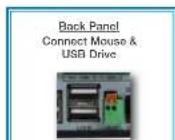
Connect a USB mouse to the USB MOUSE port on back panel of the system. NOTE: Only the USB 2.0 port on the back panel (Upper USB port) is designed for data backup to a USB flash drive. Do not connect a USB flash drive to the USB MOUSE port. (Lower USB port)
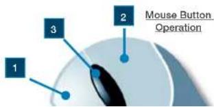
Use the mouse buttons to perform the following:
1 Left-Button:
- Click to select a menu option
- During live viewing in split-screen double-click on a channel to view the selected channel in full-screen
• Double-click the channel again to return to split-screen view - Selecting letter or number on the virtual keypad

DVR REAR
Connect Mouse & USB Drive
2 Right-Button:
- Click to open the Quick Access Menu
- Exits any window
- Exits any menu or re-opens previous menu
3 Scroll-Wheel:
- No function
PRODUCT OVERVIEW
CAMERA AND POWER CONNECTIONS
Installing Cameras
Mounting Cameras and Running Cable
Select the position for the camera and secure the camera stand. Screw the camera onto the stand. Adjust camera to the proper view angle. Make sure the lens is upright relative to the subject. Tighten the thumb bolt. First Alert cameras can be either ceiling or wall mounted by simply reversing the camera stand mounting. See "Camera Orientation" Info box. Holes are provided on both the top and bottom of the camera housing to accommodate most mounting requirements. Run cable from camera to DVR location. See Information box below on "Longer Cable Runs".

natural_image
Black security camera with mounted sensor and wall-mounted cable (no visible text or symbols)Camera - Wall Mounted


Camera Orientation
It's important the camera is mounted correctly to ensure the image is not upside down as the camera lens can only be positioned one way.

Longer Cable Runs
Longer cable runs may require an upgrade to RG59 Coax cable. First Alert kits ship with economical AV cable that is designed to work well up to the length of cable provided, usually around 60 feet. If longer distances between carriers and
DVR are required, you will need to upgrade to RG59 Coax cable. We provide several lengths up to 300 feet. In addition, if you need to run cable for in-wall installations, then you may require fire rated cable, FT-4/CMR UL approved for in-wall installations.
Step 2... Connecting Devices
Follow this diagram to make device connections. Note, some devices are not included with this kit. See "What's in the Box" for included devices.

flowchart
graph TD
    A["RCA Audio Out to Powered Speakers (Not included)"] --> B["RCA"]
    C["VGA to PC Monitor or TV BNC to Security Camera Monitor (Not included)"] --> D["Monitor"]
    E["RJ45 Ethernet to Router and Internet"] --> F["Router"]
    G["PTZ & Alarm Connections"] --> H["Computer"]
VGA to PC Monitor or TV
BNC to Security Camera Monitor
Not included)


RJ45 Ethernet to Devis and Injms
Router and Internet
PTZ & Alarm Connections
To power the system On/Off, connect the power cable to the DC 12V port on the rear panel. Flip the toggle switch on in the back of the DVR. At startup, the system performs a basic system check and runs an initial loading sequence. After a few moments, the system loads a live display view.
User Login
Password
ATTENTION: By default, passwords are disabled on the system. You do not need to enter a password when accessing any system menus. However, for security purposes, it is highly recommended to enable passwords on the system using the Password Menu. See "Password" section for details on setting up passwords. Right click and select Login. No password is required when no password is set up. Right click again to show the quick access menu
Quick Access Menu
When using the mouse, use the Quick Access Menu to access several system options, including the Main Menu. Select one of the following options:
• ID: Displays DVR ID#
- Setting: Opens the main system menu
• PTZ: Opens the PTZ control menu
- Record: Allows the user to start the record for any or all channels.

Power Switch

Main Viewing Screen

To open the Main Menu: Right-click anywhere on-screen to open the Quick Access Menu and select Setting (mouse only), or press the Menu and select Setting on the remote control or front panel of the system.
NOTE: If passwords are enabled on the system, enter 1-10 alphanumeric password to enter the Setup menu.
Display: Allows user to set the placement of channel information
Record: Allows the configuration of the recording parameters such as quality, audio and recording length. Note: Audio capable cameras (not included) are required for audio recording on the system.
Network: Use to setup the network parameters for the DVR when connected to a network.
Picture: Use to search and view snapshots that have been taken in the system.
Device: Opens the Device Setup Menu, which includes Alarm settings, look up system version information, motion detect, setting device IDs and configure PTZ, hard disk, video, IR.
System: Open the System Menu, which lets you set the date & time, user accounts, system logs, system firmware update options, and system information, language.
Password Setup
Setting Up User Permissions & Passwords
The SYSTEM categorizes users into two main groups, Local and Network.
- LOCAL USER: Refers to users who control host-end DVR
- NETWORK USER: Refers to users who control and view the DVR from a remote location via a wired or wireless network.
- Within the Network category, a Guest user can be created. Guest users will have access to channel viewing only.
When you first startup your DVR, you are automatically logged in as the ADMIN under local user and she on the network user.

Main Menu
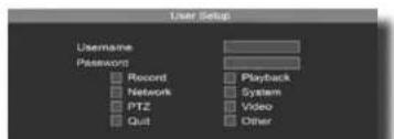
To add or edit a new Local or Network User, from the Setup Menu, choose SYSTEM and then USER. Click ok to access this menu.
- Choose Local or Network User Group.
- Click ADD to create a new user.
- Input new user name and password (required). The password is set by the ADMIN who is creating the new user.
- Select user permissions by placing a check next to the action you are allowing access. Note: Granting SYSTEM access will allow the new user to change the settings of the DVR, including the settings of the ADMIN.
- Click OK to confirm and Click OK on the User menu screen to exit.
To EDIT a Local or Network User
- Choose Local or Network User Group.
- Highlight the user you wish to edit.
- Click EDIT to change user permissions.
- Select/deselect user permissions by placing a check next to the action you are allowing access.
- Click OK to confirm and Click OK on the User menu screen to exit.
To Delete a Local or Network User
Only those users with SYSTEM access can create or edit a user permission.
- Choose Local or Network User Group.
- Highlight the User to be deleted.
- Click Delete. The system will ask you to confirm this action.
Record: Allows the USER to set the DVR to record (or not record) on one or all channels.
Network: Allows the USER to access the DVR via a remote networked connection.
PTZ: Allows the User to change PTZ parameter settings.
Quit: Allows the User to power off or Restart the DVR.
Playback: Allows the USER to playback recorded video on the DVR.
System: Gives the USER ADMIN rights to change the setup of the DVR.

Permissions Screen

NETWORK USER Permission Screen
To customize the video display on your monitor, use the DISPLAY screen. Access the DISPLAY screen from the SETUP menu, by selecting SETTING from the drop down menu, and then Display. The following screen appears.
Channel: Select the channel for setup.
Display name: Place a check in the box to select whether to display the Channel name or not.
Name: Use the virtual mouse to select a name identifier for the channel. Names are alphanumeric.
Position: The Channel name can be positioned on either the bottom or top of the channel screen view. Modify the position of the channel name as desired by selecting the appropriate drop down position.
Copy To: Apply all settings to all channels.
Video Setting Adjustments
Each camera channel can be adjusted individually for brightness, contrast and saturation. Adjustments can be made by selecting SET VIDEO from the Drop Down menu. The Video Adjustment Screen appears.
To adjust:
- Channel: Select the proper channel for adjustment using the Channel drop down.
- Brightness, Contrast & Saturation may be adjusted by placing and clicking the mouse cursor with the appropriate rectangle. Finer adjustments can be made by clicking the + and - squares.
- Repeat process for all channels as desired. Or click DEFAULT, to return video to the original factory settings.
- Click SAVE.
Video Resolution
The Video Resolution Screen allows for adjusting the video to fit or match the DVR with the monitor's video settings. This includes the Video

Display SETUP Screen

Video Adjustment Screen
system settings. The settings range from 100 (clear) to 255 (opaque)
Video Layout
The Video Layout screen allows you to customize layout of the channels to view on the monitor. Right click on home screen to select layout.
Split Screen Options:
Full Screen - Allows current channel to be displayed at full screen.
Split 4 – Shows the first 4 (lowest number channels) on the screen. Screen is divided into 4 equal square sections. 2 x 2 Matrix.
Split 8 - Shows the first 8 (lowest number channels) on the screen. Screen is divided into 1 large view channel and the remaining screen is divided equally amongst the 7 remaining channels. The lowest number channel will appear in the large screen view. Available on 8 and 16 channel DVRs.
Split 9 – Shows the first 9 (lowest number channels) on the screen. Screen is divided into 9 equal square sections. 3 x 3 Matrix. Available on 8 and 16 channel DVRs.
Split 16 - Shows the 16 on the screen. Screen is divided into 16 equal square sections. 4 x 4 Matrix. Available on the 16 channel DVR only.
Display by Turns: Check this option if you would like to have the monitor screen rotate through each channel in a full screen view. Channels will rotate every 10 seconds as a default. Channels must have a check mark in the box next to their number to be included in the rotation.
Time Interval (Second): This determines the time before the screen rotates to the next channel. The range can be set from 1 to 999 seconds. The default setting is 10 seconds.
CH1 - CH16: Check the box next to the channel number if you want to make this channel available to view on the monitor. If the check box is not placed for the channel, the camera channel will not be available for viewing on the monitor or available in the display rotation.
Additional Video Controls: Use the mouse cursor and double click in a channel view to reach a full size view of the camera channel.
Date/Time
It is highly recommended to immediately set the date and time when first setting up your system. To set the date and time From the SETUP menu

Video Layout Screen
BASIC OPERATION
RECORDING
Recording
Manual Record
There are multiple ways to set a channel to Record. The most simple way is to record all the time. Right click the mouse to reach the drop down menu. From there select RECORD by highlighting and clicking the mouse. The following screen will appear.
Select a channel to record by placing a check mark in the box to the left of the channel. Or select ALL/None to quickly select or deselect all channels for recording.
Click OK to confirm. This action will immediately place the appropriate channels into record or non-record mode. You will see a red camera show up in the lower left corner to symbolize the system is running.
Configuring Recording Channels
The DVR system provides flexibility to set the quality level and length of the recorded information.
To configure record settings:
-
From the Setting Menu, choose RECORD.
-
Using the drop down, select the channel to configure.
-
Mainstream refers to the local recording quality. Under Mainstream, choose either D1 (highest quality) or CIF or Standard. D1 is not available on the 16 channel DVR. The MB/Hour is automatically set to 300 for D1 and 160 for CIF. These settings can be changed/ lowered. Lowering the MB/Hour lowers the quality of the recording, but saves hard drive space.
-
Minor stream refers to the video stream available when accessing the DVR from a network or mobile device. Under Minor stream, the choices are CIF, QCIF and Closed.
Minor MBPH (MB/Hour): network transmission file size per hour.
Minor frame rate: there are "25fps", "20fps" and "12fps" optional.
- Record Audio: Select the button to record audio in local and client. Camera must be audio capable.
A. Miss Andley, O'cast the button as that you can play the audio file.

8 Channel Drop Down Menu RECORD Screen

Configuring Recording Channels

BASIC OPERATION
RECORDING

CCTV Resolution
CCTV resolution is measured in vertical and horizontal pixel dimensions and typically limited by the capabilities of both the camera and the recorder that you are using for your CCTV surveillance installation, CCTV systems use an analog video signal. For television specifications (which CCTV uses) the highest resolution that can be captured and stored
is 704 x 480 (NTSC for the United States) and 720 x 576 (PAL for Europe). This resol resolution. A high end CCTV recorder is capable of recording at up to D1 resolution.
CCTV Resolutions
D1:704×480
HD1 (2CIF): 704 x 240
CIF: 352 x 240
QCIF: 176 x 120
Motion Detection Setup
Motion detection is configurable on each channel. Configure motion detection as follows:
- Right click and select Setting click DEVICE. Then click MOTION DETECT. This will bring up the Motion Detection Main screen.
- Use the drop down box to select the channel to configure.
- Click the ENABLE MD checkbox to activate the motion detection on this channel.
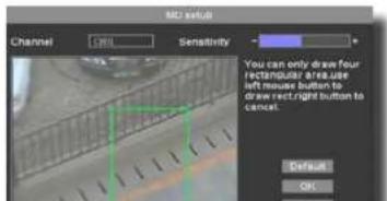
- Click on SET MD to reach the Motion Detection Sensitivity Screen which allows the setting of the sensitivity level of detection.
- Set the sensitivity by clicking within the Sensitivity
-
- rectangle to the appropriate level desired.
- Click OK on the MD SETUP screen and then OK again on the MOTION DETECT screen to confirm.
- By default, any motion with the entire camera view will activate motion detection. The DVR system will allow you to limit motion detection within the camera area as desired. To choose an area to enabling motion detection, place the cursor inside the camera view of the Motion Detection Sensitivity Screen. Drag and click over the area you want motion to be detected. A green rectangle is formed. Up to four areas can be created. The result is that the area within any of the green rectangles will detect motion. Click OK to confirm.
Motion Detection Alarm Settings
Motion detection can trigger recordings, buzzer alarms, an alarm output control signal, and a preset position on a connected PTZ camera - (purchased separately.) To set Motion Detection alarms do the following:

Motion Detection Main Screen
BASIC OPERATION
PLAYBACK
SnapShot Picture Management
Live SnapShot
Executing a snapshot is easy. To take a snapshot
- Double click in camera view to see a full screen view of the camera channel.
- Right click the mouse to access the quick menu drop down
- Click SNAP SHOT. A pop up remark will appear stating the channel name and confirm the taking of a snapshot.
Recording Snapshot
A snapshot picture can be taken of a recorded video. To take a recorded snapshot
- Right click the mouse to access the quick menu drop down and select playback
- Highlight the recording that holds the desired snapshot.
- Click PLAY.
- While recording is being played, click on the Camera ICON in the Play menu screen. A pop up remark will appear stating the channel name and confirm the taking of a snapshot
Snapshot Review
Snapshots are accessible through the PICTURE Menu.
To reach the PICTURE menu, do the following:
- Right Click, Select SETTING from the Drop Down menu.
- Click PICTURE. This will bring up the Picture Review Screen
To Review Snapshot
- Choose the Channel No. or ALL
- With the virtual mouse, input the date of the Snapshot for review
- Click SEARCH. This will bring up a list of snapshots taken on that day for the channel (s) selected.
- Highlight the snapshot of interest to view the snapshot on the screen. Use these navigation buttons:
means the first page, previous, next and the end page.
means the previous page

Picture Review Screen
BASIC OPERATION
PLAYBACK
flash drives, with capacities from 256 MB to 4 GB.
Video Playback
Recorded video is accessed through the Search Recording screen. To access the recordings, right click the mouse to access the quick menu drop down. Select PLAYBACK. The SEARCH RECORDING screen will appear on screen.
To Find & Play Recordings:
- Choose the target channel to search recordings on, or select ALL.
- Select the TYPE of recording by using the drop don. Selections include Manual, Schedule, Motion Detect MD, Alarm and All.
- Input recording search date using the virtual mouse. The file list will show all recordings available based on your selection criteria.
- Search with the file list shown by page using the following buttons.
means the first page, previous, next and the end page.
means the previous page
means the next page
H means the end page
LATEST: REVERSES TO SHOW THE MORE RECENT VIDEO. GOTO: EACH VIDEO RECORDING IS PROVIDED A NUMBER ON THE LEFT SIDE OF THE FILE. INPUT THE VIDEO RECORDING DESIGNATED NUMBER AND PRESS GOTO TO FIND A PARTICULAR VIDEO NUMBER.
- Highlight the recording to play back and select PLAY.
Recording Backup
- Place a formatted USB into one of the USB slots on the back panel of the DVR. Make sure there is enough room on the USB device for the recording to be backed up.
- Highlight the recording file to be backed up, from the file list selection.
- Click the Backup Icon.
The file will be backed up on the USB disk.
NOTE: The system is compatible with most major brands of USB flash drives, with connection from 256 MB to 4 GB. Backup files comp

Search Recording Screen

| Play | Starts playback of selected video | |
| Pause Pauses the playback | ||
| Play by Frame | Moves recording frame by frame | |
| Slow Play | Reduces the playback speed to 1/4X | |
| Fast Play | Increase the play speed up to 4X | |
| Snapshot | Takes a snapshot with the recording. Access to | |
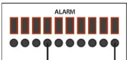
Use the Alarm In feature to configure alarm settings. To access the Alarm In feature, right click the mouse to access the quick access menu under setting. Select Device and select Alarm In. NOTE: External alarm devices must be connected to the alarm block on the rear panel of the DVR in order to use the I/O (input/output) alarms of the system. See page 23 "Alarm Inputs" and "Alarm Inputs Diagram" for details on attaching alarm inputs.
Alarm Input ID:
Select which switch on terminal block to be used for alarm (1-4).
Work Mode:
Set alarm to normally open device or normally closed device.
Copy To:
Copy settings to specific alarm inputs.
Clear Alarm:
When alarm is activated, press Clear Alarm to turn alarm off.
Default:
Set "alarm input" back to default settings.
Set Alarm:
See page 19

Alarm Input Menu
ADVANCED OPERATION
ALARM
Alarm Inputs:
Alarm inputs are devices or switches that activate when a door, window, cabinet etc. is opened or accessed. For example, you might want to only have the camera record when someone opens a tool cabinet or when a door opens vs. recording when motion occurs around those areas. There may be people moving by those areas frequently but you are only concerned about when those areas are accessed. This saves hard drive space and makes it easier to find an event that was recorded to the hard drive.
Select Alarm in Module
Alarm Input cables of device of Alarm in: one is connected with "COM" port, the other is connected with the port "1/2/3/4" (This should be in accordance with Alarm Input ID 1/2/3/4 in DVR software). The below figure shows the Alarm Input cable has been connected with Port 1, so the Alarm Input 1 should be set in DVR software.
Alarm Output:
Alarm output is used to activate an external device such as a horn or light after an alarm is triggered. To do this the DVR uses a dry contact normally open relay. To configure alarm outputs, connect the external device to the out connections on the alarm block as required by the device. The maximum contact rating is 24 VDC @ 3A. Alarm input can start recording on any one of the camera channels.
ADVANCED OPERATION
SYSTEM
System Info and System Update
Shutdown System
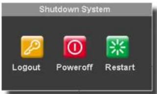
The system provides the ability with a controlled shut down, through a power down or with a Restart. To access the shut down system menu, right click the mouse to see the drop down quick menu and then select Shutdown. The following screen appears.
Power off: Power Off shuts the system down in a controlled manner. The hard drive is kept running. If user wants to shutdown fully, user needs to turn off the button on back panel of DVR.
Restart: Provides the user with a restart. The system will shut down and restart in a controlled way.
Logout: Logs the user out. A request activity to the DVR from any user will require a login and password to gain access to the system.
Log
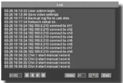
The DVR system logs certain events. This log can be backed up with the use of a connected USB device as a .txt file.
The system log shows 16 actions per page. If you want to check any page, enter the page no into Goto box. 📋/↗/ mean the first page, previous, next and the end page. System log can be backup to USB Device.
Update
Firmware updates may be available periodically. They will be made available for download onto a USB disk from the First Alert as needed. Please see FirstAlert.com/ Home Security/Security Cameras.
Place a USB device into the slot on the rear panel of the DVR. Make sure it is formatted and has enough space to accommodate the firmware.
Choose USB from the METHOD drop down.
Click Update.
The other Methods HTTP or URL are not available for use at this time.

ADVANCED OPERATION
PTZ
Pan tilt zoom...PTZ
Pan/Tilt/Zoom (PTZ) Setup:
Note: Consult the instruction manual of your PTZ camera for complete information about your camera, including protocol, baud rate and parity settings before beginning setup. Enter these settings in the DVR.
STEP 1: Connect your PTZ Camera to this DVR
Connect a PTZ camera to the BNC and DC power cables. Also, connect the communication cable from the PTZ camera to the 485A (TX, +) and 485B (RX, -) control inputs to the PTZ block on the back of the DVR. Note there is only one set of PTZ control inputs (485A & 485B), however multiple PTZ cameras can be set up by making parallel connections. See diagram for details and see "PTZ Camera Setup" Info box for additional information.

PTZ Camera Setup
NOTE: It is recommended for best results to use 120Ω shielded twisted pair cable of a sufficient gauge to meet your application length. 18 to 22 gauge is usually sufficient. In addition, be sure to
only install the 120Ω terminating resistor that comes with your PTZ camera in the last parallel connected camera. Keeping that resistor in all cameras can possibly degrade the signal and can cause unexpected or loss of operation and control.
Step 2: Configure PTZ Communication Settings
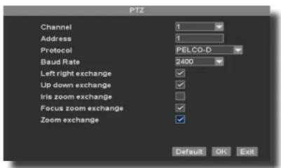
To access this menu, from the setup menu click DEVICE. Then PTZ. This will bring up the PTZ setup screen. PTZ setting options for each camera can be selected independently for each camera channel
- Select the appropriate channel connected to the PTZ camera using the drop down
- Under ADDRESS, enter an address from 001-255 using the virtual keyboard
- Under protocol, select the appropriate protocol based on the

ADVANCED OPERATIONS
PTZ SETUP
Step 3: Configure the operation & control of your PTZ camera(s):
In live view, double click on the channel with the connected PTZ camera to open to full screen view. This selects the channel to configure and control.
- From the quick access menu select PTZ, this will bring up the PTZ manual control screen
- From the PTZ setup screen you can adjust:
- Pan speed: Adjusts the speed (1-255) the camera will move while being controlled manually. Certain PTZ camera will use only part of the range.
- Zoom: "+" zooms in and "-" zooms out
• Focus: "+" and "-" focuses the picture. - Iris: “+” lets more light in and “-” removes light from the picture. This is useful to correct backlight issues.
- Directional keys: left and right arrows control the pan; up and down arrows control the tilt.
Setting Of Presets
Presets are camera positions setup in advance. The DVR can control the camera to move the PTZ camera to the proper preset position.
To set up a preset, click more from the PTZ manual control screen, to gain access to the PTZ patrol screen. and then click set to create preset positions. See PTZ preset screen.
To set up a preset use the ptz preset screen. do the following:
- Use the directional arrows to set camera to the preset position desired.
- Place a preset number in the box next to add and input the length of time, number of seconds you would like the preset to be positioned at the preset.
- Click add. The newly added preset will now be available in the preset drop down field.
- Repeat the process to add the proper number of presets desired.
Viewing A Preset
Presets may be viewed by selecting the appropriate preset using the drop down and then clicking goto, this can be accomplished on

PTZ Manual Control Screen

PTZ Preset Screen
REMOTE ACCESS
NETWORK SETUP
Network Setup for Remote Access
Network Setup for Remote Access
Your Auto ID system is capable of connecting to a local area network (LAN) to view remotely, without the use of port forwarding. Please follow the steps below.
1. Right click and select setting. Then select Network will allow you to view all of your network settings.
2. Plug the Ethernet cable from your router the Ethernet port on the back of the DVR.
3. Plug the ethernet cable from the DVR to a free ethernet port on the router.
4. Make sure "Automatic DHCP" is check marked.
5. Your IP address, subnet mask, DNS, and gate will automatically populate AFTER you restart the DVR.
6. Port should stay at 9101.
7. Exit out of the network screen and on the DVR system, right click and select Net Status from the list of options (pictured right).
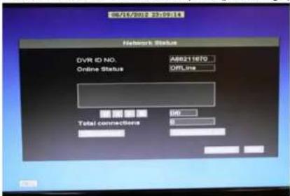
- This will display your unique Auto ID Code along with your online status. Online status should say online when you have connected the Ethernet cable into the Ethernet port on the DVR. You must also have internet on your home network for this to work (pictured below).
- You must install the Smartbridge software to your computer to view the cameras locally or remotely
ID:A68211870
Setting
PTZ
Record
Playback
Net Status
Snapshot
Set video
Layout
Split 4
Split 8
Split 9
Shutdown
REMOTE ACCESS
NETWORK SETUP
wizard is finished. Double click the icon to run the Smartbridge Software.


REMOTE ACCESS
NETWORK SETUP
- The connect tab is for connecting to one SmartBridge DVR only. Use the advanced Tab when connecting to multiple Smartbridge DVR's at once. (Group). See adding groups section.

- Click Port to enter the port settings. This is to assign a router port that is open. Typically, this is set to 9101 (recommended)

REMOTE ACCESS
NETWORK SETUP
- You are now connected to the SmartBridge DVR remotely. All cameras that are connected to your SmartBridge system should now be shown on the Smartbridge software screen.

REMOTE ACCESS
NETWORK SETUP
 | Press this button to connect all cameras connected to the Auto ID system. Also, Right click on a camera source screen and select connect. |
 | Press this button to disconnect all cameras connected to the Auto ID system. Also, Right click on a camera source screen and select disconnect. |
 | Press this button to Record to an external hard drive (80gb or larger required) |
 | Press this button to take a snapshot image of a selected camera window. Image is automatically saved to the external hard drive. (80gb or larger required) |
 | Press this button to play video recorded to the external drive after the record external button has been pressed. |
 | Press this button to select the advanced settings features. |
 | Press this button to open the settings window. |
 | Press this button to isolate all connected cameras to POP Up windows which can be easily moved around on the desktop. |
REMOTE ACCESS
RECORD EXTERNAL
RECORD EXTERNAL
You are able to record using the remote software simultaneously to recording on the Smartbridge DVR system. In order to record using the Smartbridge remote software, you will need an 80 GB minimum external hard drive formatted to FAT32.
- Plug an external hard drive into your computer. Your operating system should associate a drive letter to the hard drive. Once the hard drive is connected,

- Click the settings button and click the storage tab. The drive letter your operating system associated to the external device is visible in the list. Check the drive letter that you want the recordings
to be saved to...

REMOTE ACCESS
PLAYBACK EXTERNAL
Connect
Disconnect
Start Recording
Stop Recording
Open Audio
Close Audio
Remote Playback Control
Start Master Recording
Stop Master Recording
Start Talking
Stop Talking
Set Remotely

- Select a Channel, Click to the external hard drive.
to capture a still image of a camera in view. This image will be saved
PLAYBACK EXTERNAL

- Select Playback external
to play back recorded files.


REMOTE ACCESS
PLAYBACK EXTERNAL
| Opens a saved .sv5 file to play. | |
| Plays a recorded video | |
| Stops a recorded video during playback | |
| Click repeatedly to Fast Forward at different speeds of a recorded video | |
| Click repeatedly to play a Slow forward speed of a recording. | |
| Click repeatedly for reverse playback of a recording | |
| Manually set slow playback. | |
| Takes a snapshot of a recording | |
| No Function | |
| No Function | |
| Plays all recordings |
| Shows One Screen | |
| Shows four channels in four screens | |
| Shows nine channels in nine screens | |
| Shows sixteen channels in sixteen screens | |
| Shows selected channel in full screen | |
| Saves a recording to an .sv5 file on the hard disk | |
| Shows the times recordings started in a list view. |
| Shows One Screen | |
| Shows four channels in four screens | |
| Shows nine channels in nine screens | |
| Shows sixteen channels in sixteen screens | |
| Shows selected channel in full screen | |
| Saves a recording to an .sv5 file on the hard disk | |
| Shows the times recordings started in a list view. |
REMOTE ACCESS
SETTINGS
Settings

Select to adjust specific settings for your Smartbridge DVR. (See recording external for Storage Tab information) Select the Advanced Tab.

Check the Place system always on top box to place the Smartbridge on top of all other software within the operating system.
REMOTE ACCESS
ADVANCED SETTINGS
Advanced Settings

Select to open the advanced settings options for your Smartbridge DVR

- Switch User (Feature enabled in advanced mode only): Switches between users (see setting up groups)
- TV Mode: Select TV mode to place all connected channels to share the full screen. Right click to exit TV Mode.

REMOTE ACCESS
PAN TILT ZOOM
Pan Tilt Zoom
If you have pan tilt zoom cameras installed, you are able to control the pan tilt zoom cameras remotely with the Smartbridge Software.

| Press to move PTZ camera up | |
| Press to move PTZ camera left | |
| Press to move PTZ camera down | |
| Press to move PTZ camera right | |
| Iris | Adjust the color of the PTZ camera |
| Focus | Adjust the focus of the PTZ camera |
| Zoom | Zoom in and out |
Setting Up Groups
With the Smartbridge Software, you are able to set up multiple DVR's for remote viewing called groups. This is beneficial if you have multiple locations requiring surveillance. To set up a group, you need to have more than one Smartbridge DVR connected to a network. Select the Advanced Tab

REMOTE ACCESS
SETTING UP GROUPS
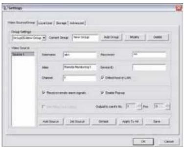
To add a group, Select settings
To add a group, select the Video Source/group Tab
- Select add group.
- Type the name of the group in the current group box.
- Select Modify to save the new group.
o Enter the username and password
o Enter an Alias name for the group.
o Enter the Device ID of your Smartbridge DVR system for the group
o Select receive remote alarm signals if you want
to receive an alarm alert for your Smartbridge DVR
o Select Enable Pop Up to enable pop ups - Select add source to add a camera source
- Select DEL Source to delete a camera source
- Select Default to revert back to default settings
- Select Apply to all to apply all settings to all
camera sources within the group - Select Save to save all settings.
Select the Local User Tab to add user rights/permissions to the Smartbridge Software. You are able to add users to the Smartbridge Remote viewer software. Administrator has full access to the all features. General user has viewing capability only.

Web service - currently not function
Mobile service - to enable mobile browsing
Port - this is the web port which should always be at 80
Quality- selects the quality of the streaming video
Channel - select channel you would like to apply settings to
Device ID - shows your DVR ID number
FPS - frames per second. The higher the fps, the better
Register- No function
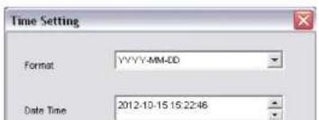
Set time- set date and time
![Geometry Settings Custom Settings [Custom Settings] - Service Type Language: Format: Resolution: Size: Translation: ADD Service: Model Dataset: Create Set: Change: Set New Save As Edit Import Export Export Export Export Export Export Export Export Export Export Export Export Export Export Export Export Export Export Export Export Export Export Export Export Export Export Export Export Export Export Export Export Export Export Export Export Export Export Export Export Export Export Export Export Export Export Export Export Export Export Output](/content/2026/06/1247365/images/82867c9cb85629e34fbb0ee91ce9c3eb677ca61b79a3a6e6328b5e6669b1a375.jpg)
Channel -select channel of the PTZ
Ch name – give the channel number a name
Main - quality of camera -
CIF or D1 on 4/8 channel
Standard/Net Mode on 16 channel
Minor- low quality of camera-
Select QCIF, CIF or None.
PAL/NTSC -default is NTSC
Audio- turns audio on or off (only works if a mic is installed)
Position - Changes the position of the date and time and ch. No.
Select Left down, Left up, or None.
Main size- chose the size of the file for streaming.
Size is by MB/H(megabytes per hour)
Minor size- chose the lowest number of MB/H

Device Logs Screen
APPENDIX
HARD DRIVE
Hard Drive Removal and Installation
HDD Installation
To replace the hard drive in the DVR:
1. CAUTION: TO REDUCE THE RISK OF ELECTRIC SHOCK, UNPLUG ALL POWER SOURCES, INCLUDING CAMERAS FROM THE DVR BEFORE REMOVING COVER. FAILURE TO DO SO CAN RESULT IN DAMAGE TO THE DVR OR ITS COMPONENTS AS WELL AS INJURY OR DEATH
2. Remove screws securing the cover of the DVR and remove cover.
3. Disconnect the hard drive power and data cables.
4. Remove old hard drive and replace with the new one.
5. Re-install the screws securing the hard drive to the bottom of the DVR.
6. Re-connect the hard drive power and data cables.
7. Replace the cover and screws. Note: Format hard drive per instructions in HDD MANAGEMENT section.

Caution!
When working with electrostatic sensitive devices such as hard disk or DVR unit, make sure you use a static-free workstation. Any electrostatic energy
coming in contact with the hard disk or DVR can damage it permanently.

natural_image
Technical line drawing of a rectangular enclosure with mounting holes and ventilation grilles (no text or symbols)Hard Drive Remove/Install Screws from Below

Hard Drive Format
APPENDIX
SPECIFICATIONS
Technical Specifications
| Item Device Parameter Specification | ||
| System | Language English/ Spanish/ French | |
| GUI 16 Bit Graphic menu (OSD Menu) | ||
| Password User password, Administrator password | ||
| Video | Video in 4/8/16 channel composite video Input 1.0Vp-p, Impedance 75Ω, BNC | |
| Video out 1 VGA, 1 BNC (CVBS) | ||
| Video display 4/8/16 channel: 1/4/8/9 | ||
| Video standard | PAL, (Europe) 25 f/s, CCIR 625line, 50 sceneNTSC, (US) 30 f/s, CCIR 525 line, 60 scene | |
| Audio | Audio input 2-ch audio input, impedance 600Ω, RCA | |
| Audio output 1-ch audio output, impedance 600Ω, RCA | ||
| Record style Audio video recorded simultaneously | ||
| Audio compression ADPCM | ||
| Picture processing and storage | Picture compression H.264 | |
| Picture resolution | CIF/D1 | |
| Audio style | ADPCM | |
| Video code rate | CIF: 384~768 KbpsD1: 512~1024 Kbps | |
| Audio code rate | 32 KB/s | |
| Data storage | 500 GB or 1 TB SATA HDD Included, up to 2 TB capable | |
| Alarm | Alarm Input | 4 alarm Input |
| Alarm output | 1 alarm output | |
| PTZ interface | Supports PELCO-D | |
APPENDIX
FAQ'S
FAQ's
If your problem is not listed below, please call our toll-free number for more support. Tech Services: 800-323-9005.
Question: Why does DVR not work after starting? Why did the DVR stop working?
Answer:
- Check that the power adapter is plugged into the DVR properly
- Check the power source and all power cord connections are properly connected
• Make sure the power on-off switch on the back of the DVR unit is on
Question: Why does the DVR reboot automatically? Or stop for several minutes after starting?
Answer:
- Check the supply voltage to be sure it is stable
• Bad track on hard drive or the hard drive is bad
• Instability of the front-end video signal
• High temperature, too much dust, bad DVR operating environment
Question: Why is there no video output on single, multi or all channels?
Answer:
- Check if the camera adaptor is properly connected
- Check the cable for connecting video input/output in the back panel of DVR
- Insert the video source directly into the display device and check if they are causing the problem.
- Check the brightness of the picture and bring it back to its original default setting
• No video input signal or too weak
Question: What is the meaning of?
Answer:
| Indicates the channel is recording. | |
| Channel is capable of providing audio. | |
| Motion detected. | |
| Indicates motion record enabled. | |
| Indicates a remote log in session is in progress. |
APPENDIX
FAQ'S
Question: Why is there no audio when playing back?
Answer:
- Check to see that the audio settings for the channels are correct.
• Audio is off in record menu
Question: Why is my system time not correct?
Answer:
- Wrong setting or user did not click OK to confirm
Question: Why doesn't motion detection work?
Answer:
• The setting of motion detection area is not correct
• Sensitivity is too low
Question: Why do I have no disc or disc mount error?
Answer:
• The data being downloaded exceeds the capacity of backup device
• The backup device is incompatible
• The backup device is damaged
Question: Why doesn't the Remote Control work?
Answer:
• The remote control is too far from the DVR
• Remote control batteries are dead or low
• Remote control is damaged, check by using the control on the DVR
Question: Why can't I log in over the Internet?
Answer:
- Check the network to see if it is connected. Check if LINK or 100M LED is displayed normally on
the panel; use ping xxx.xxx.xxx.xxx (DVR IP) to check if the Internet is linked properly.
• Make sure you are running Windows 7, Vista or XP operating system and Internet Explorer 6.0 - 8.0
APPENDIX
TROUBLESHOOTING
Troubleshooting
| Error Possible Cause Solutions | ||
| System is not receiving power or is not powering up | Cable from power adapter is loose or is unplugged | Confirm that all cables are connected correctlyConfirm that the power adapter is securely connected to the back of the unit |
| Cables are connected, but system is not receiving sufficient power | Confirm that the system is powered on (LED Indicators on the front should be ON)If the unit is connected through a power bar or surge protector, try bypassing the bar and connecting the power directly to the wall outletConfirm that there is power at the outletConnect the power cable to another outletTest the outlet with another plugged device | |
| Remote control not detected by the system | Battery In the remote control is drained or is missing | Install two fresh AAA alkaline batteries in the remote control |
| Hard drive is not detected by the system | Hard drive cables are loose or not properly connected | Remove the housing and check that hard drive cables are firmly connected |
| Open the housing and install a 3.5 SATA hard drive | ||
| Mouse not detected by system | Mouse cable is not connected or is not firmly connected to the system | Firmly connect the mouse cable to the USB Mouse port (not the USB Data port) on the front panel. |
| System needs to be reset | Power off the system (Turn power switch off position on back of unit). Firmly connect a USB mouse to the USB Mouse port on the front panel of the system. Power on the system (Turn power switch to on position on back of unit). | |
| There is no picture on selected channels/camera picture is not being displayed | Camera cables are loose or have become disconnected | Check the camera video cable and connectionsDisconnect and reconnect the cable at the system and at the cameraTry moving the camera to another channel or use another cable |
| Audio cables are loose or have been disconnected | Check the AUDIO connections to the DVR | |
Audin cables are loose or have been disconnected •
Check the AUDIO connections in the DVR
APPENDIX
WARRANTY
Warranty
PRODUCT LIMITeD WARRANTY
BRK Brands, Inc., ("BRK") the maker of First Alert® brand products warrants that for a period of one year from the date of purchase (the "Warranty Period"), this product will be free from defects in material and workmanship. BRK, at its sole option, will repair or replace this product or any component of the product found to be defective during the Warranty Period. Replacement or repair will be made with a new or remanufactured product or component. If the product is no longer available, replacement may be made with a similar product of equal or greater value. This is your exclusive warranty.
This warranty is valid for the original retail purchaser only from the date of initial retail purchase and is not transferable. In order to obtain warranty service, you must keep the original sales receipt and proof of purchase in the form of the UPC code from the package. BRK dealers, service centers, or retail stores selling BRK products do not have the right to alter, modify or any way change the terms and conditions of this warranty.
WARRANTY eXCLUSIONS
Parts and Labor: 1 year limited (warranted parts do not include bulbs, LEDs, and batteries)
This warranty does not apply to bulbs, LEDs, and batteries supplied with or forming part of the product.
This warranty is invalidated if non- BRK accessories are or have been used in or in connection with the product or in any modification or repair is made to the product.
This warranty does not apply to defects or damages arising by use of the product in other than normal (including normal atmospheric, moisture and humidity) conditions or by installation or use of the product other than in strict accordance with the instructions contained in the product owner's manual.
This warranty does not apply to defects in or damages to the product caused by (i) negligent use of the product, (ii) misuse, abuse, neglect, alteration, repair or improper installation of the product, (iii) electrical short circuits or transients, (iv) usage not in accordance with product installation, (v) use of replacement parts not supplied by BRK, (vi) improper product maintenance, or (vii) accident, fire, flood or other Acts of God.
This warranty does not cover the performance or functionality of any computer software included in the package with the product. BRK makes no warranty that the software provided with the product will function without interruption or otherwise be free of anomalies, errors, or "Bugs." This warranty does not cover any costs relating to removal or replacement of any product or software installed on your computer.
BRK reserves the right to make changes in design or to make additions to or improvements in its products without incurring any obligations to modify any product which has already been manufactured. BRK will make every effort to provide updates and fixes to its software via its website. This warranty does not cover any alteration or damage to any other software that may be or may become resident on the users system as a result of installing the software provided. This warranty is in lieu of other warranties, expressed or implied, and BRK neither assumes nor authorizes any person to assume for it any other obligation or liability in connection with the sale or service of the product. In no event shall BRK be liable for any special or consequential damages arising from the use of the product or arising from the malfunctioning or non-functioning of the product, or for any delay in the performance of this warranty due to any cause beyond its control.

natural_image
Blank white image with no visible content, text, or symbols- INTRODUCTION
- KEY PRODUCT FEATURES
- Main Description
- Product Features
- TABLE OF CONTENTS
- SAFETY
- CAUTION STATEMENTS
- Safety Precautions
- Instructions for Use
- FCC Compliance
- FCC Compliance Class B Digital Device
- FCC Certification (if applicable)
- PRODUCT OVERVIEW
- PACKAGE CONTENTS
- What's in the Box\*
- DVR CONTROLS
- REMOTE CONTROL
- Remote Control Operation
- Changing Batteries
- MOUSE AND VIRTUAL KEYPAD
- Mouse Controls
- Mouse Operation with this DVR
- Left-Button:
- Right-Button:
- Scroll-Wheel:
- CAMERA AND POWER CONNECTIONS
- Installing Cameras
- Mounting Cameras and Running Cable
- Camera Orientation
- Longer Cable Runs
- Step 2... Connecting Devices
- User Login
- Password
- Quick Access Menu
- Password Setup
- Setting Up User Permissions & Passwords
- To EDIT a Local or Network User
- To Delete a Local or Network User
- Video Setting Adjustments
- Video Resolution
- Video Layout
- Split Screen Options:
- Date/Time
- BASIC OPERATION
- RECORDING
- Manual Record
- Configuring Recording Channels
- CCTV Resolution
- CCTV Resolutions
- Motion Detection Setup
- Motion Detection Alarm Settings
- PLAYBACK
- SnapShot Picture Management
- Live SnapShot
- Recording Snapshot
- Snapshot Review
- To Review Snapshot
- Video Playback
- To Find & Play Recordings:
- Recording Backup
- Alarm Input ID:
- Work Mode:
- Copy To:
- Clear Alarm:
- Default:
- Set Alarm:
- ADVANCED OPERATION
- ALARM
- Alarm Inputs:
- Select Alarm in Module
- Alarm Output:
- SYSTEM
- System Info and System Update
- Shutdown System
- Log
- Update
- PTZ
- Pan tilt zoom...PTZ
- Pan/Tilt/Zoom (PTZ) Setup:
- STEP 1: Connect your PTZ Camera to this DVR
- PTZ Camera Setup
- Step 2: Configure PTZ Communication Settings
- ADVANCED OPERATIONS
- PTZ SETUP
- Step 3: Configure the operation & control of your PTZ camera(s):
- Setting Of Presets
- Viewing A Preset
- REMOTE ACCESS
- NETWORK SETUP
- Network Setup for Remote Access
- RECORD EXTERNAL
- PLAYBACK EXTERNAL
- SETTINGS
- ADVANCED SETTINGS
- PAN TILT ZOOM
- Setting Up Groups
- APPENDIX
- HARD DRIVE
- Hard Drive Removal and Installation
- HDD Installation
- Caution!
- Hard Drive Format
- SPECIFICATIONS
- FAQ'S
- Question: Why is there no audio when playing back?
- Answer:
- Question: Why is my system time not correct?
- Question: Why doesn't motion detection work?
- Question: Why do I have no disc or disc mount error?
- Question: Why doesn't the Remote Control work?
- Question: Why can't I log in over the Internet?
- TROUBLESHOOTING
- WARRANTY
- PRODUCT LIMITeD WARRANTY
- WARRANTY eXCLUSIONS
Brand : FIRST ALERT
Model : DCA8405-520
Category : Security Camera