
BG-UM88-150L - Gps BZBGear - Free user manual and instructions
Find the device manual for free BG-UM88-150L BZBGear in PDF.


| Product Type | 8x8 HDBaseT Matrix with HDMI and HDBaseT outputs |
| Model | BG-UM88-150L |
| Brand | BZBGear |
| Video Inputs | 8 x HDMI Type A (19-pin female) |
| Video Outputs | 8 x HDMI Type A + 8 x HDBaseT (RJ45), mirrored |
| Max Video Resolution | 4K2K@60Hz (YUV 4:4:4) |
| Video Bandwidth | 18Gbps |
| HDR Support | HDR10, HDR10+, Dolby Vision, HLG |
| HDBaseT Transmission Distance | Up to 150m (1080p) / 120m (4K) via Cat5e/6/7 |
| Audio Formats | LPCM up to 7.1, Dolby TrueHD, DTS-HD Master Audio, etc. |
| Audio De-embedding | Coaxial (3.5mm) and balanced analog (5-pin Phoenix) outputs |
| Control Methods | Front panel buttons, IR remote, RS-232, LAN (Web GUI) |
| IR Matrix | One-to-one at matrix end; follows HDMI video at receiver end |
| EDID Management | 21 factory presets, 2 user-defined, copy from HDMI/HDBaseT outputs |
| CEC Control | Yes |
| POC (Power over Cable) | 24V POC on all HDBaseT ports |
| Power Supply | AC 100-240V 50/60Hz, 125W max |
| Matrix Dimensions (W x D x H) | 440 x 374 x 88.6 mm (1U rack mount) |
| Receiver Dimensions (W x D x H) | 140 x 65 x 18 mm |
| Matrix Weight | 6.54 kg |
| Receiver Weight | 155 g |
| Operating Temperature | 0°C to 40°C |
| Safety | Surge protection recommended |
| Maintenance | Clean with dry cloth; avoid liquids |
| Spare Parts / Support | Contact BZBGEAR support (bzbgear.com/support) |
Frequently Asked Questions - BG-UM88-150L BZBGear
User questions about BG-UM88-150L BZBGear
0 question about this device. Answer the ones you know or ask your own.
Ask a new question about this device
Download the instructions for your Gps in PDF format for free! Find your manual BG-UM88-150L - BZBGear and take your electronic device back in hand. On this page are published all the documents necessary for the use of your device. BG-UM88-150L by BZBGear.
USER MANUAL BG-UM88-150L BZBGear
User Manual
Contact
Thank you for purchasing this product
For optimum performance and safety, please read these instructions carefully before connecting, operating or adjusting this product. Please keep this manual for future reference.
Surge protection device recommended
This product contains sensitive electrical components that may be damaged by electrical spikes, surges, electric shock, lighting strikes, etc. Use of surge protection systems is highly recommended in order to protect and extend the life of your equipment.
Table of Contents
- Introduction....1
- Features....1
- Package Contents....2
- Specifications....2
- Operation Controls and Functions....4
5.1. Matrix Panel....4
5.2.HDBaseT Receiver Panel 6 - IR Remote 7
- IR Control System......8
- IR Cable Pin Assignment....10
- EDID Management....10
- Web GUI User Guide....12
- RS-232 Control Command....19
- Application Example....24
- Tech Support....25
- Warranty....25
- Mission Statement....Back cover
1. Introduction
The BG-UM88-150L-KIT 18Gbps 8x8 HDBaseT(150M) Matrix can connect 8 HDMI sources to 16 displays. The eight HDMI outputs are mirrored to eight HDBaseT outputs that run simultaneously. The HDBaseT output can extend a 4K2K@60Hz 4:4:4 resolution signal up to 492ft /150m via a single Cat 5e/6/7 cable. Audio can be de-embedded via the analog and digital coax ports. Each HDMI output independently supports 4K2K to 1080P downscaling. Featuring IR matrix, the IR signal is one-to-one control at the Matrix end, but the IR signal follows the HDMI video signal at the HDBaseT Receiver end.
This product provides an intuitive OLED menu screen and supports control via front panel buttons, IR remote, RS-232, LAN, and Web GUI.
2. Features
☆ HDMI 2.0b, HDCP 2.2 and HDCP 1.x compliant
☆ Video resolution up to 4K2K@60Hz (YUV 4:4:4) on all HDMI & HDBaseT ports
8 HDMI inputs, 8 HDMI & HDBaseT mirrored outputs
☆ HDMI ports transmit 18Gbps lossless uncompressed video bandwidth
18Gbps lossless compressed HDBaseT signal transmission
☆ 4K->1080P Down Scaler on each output port
HDR, HDR10, HDR10+, Dolby Vision, HLG are supported
☆ HDBaseT output can extend video transmission distance up to 492ft / 150m for 1080P, or 394ft / 120m for 4K2K using a single Cat 5e/6/7 cable
HDMI audio pass-through up to 7.1CH HD audio (LPCM, Dolby TrueHD and DTS-HD Master Audio)
☆ IR matrix
☆ Audio de-embedded via analog and coax ports
☆ Advanced EDID management and CEC control
☆ 24V POC on all HDBaseT ports
☆ 1U rack mounted design with front panel OLED display
* Control options include the front panel buttons, IR remote, RS-232, LAN, and Web GUI
3. Package Contents
① 1 x BG-UM88-150L Matrix
② 8 x HDBaseT Receivers
③ 1 x Matrix IR Remote
④ 1 x 100\~240V AC 50/60Hz Power cable
⑤ 1 x RS-232 serial cable (1.5 meters, male to female head)
⑥ 8 x 3-pin Phoenix Connectors & 8 x 5-pin Phoenix Connectors
⑦ 9 x IR Blaster cables (1.5 meters)
⑧ 9 x IR Receiver cables (1.5 meters)
⑨ 18 x Mounting Ears (Matrix and Receiver)
1x User Manual
- Specifications
| Technical | |
| HDMI Compliance | HDMI 2.0b |
| HDCP Compliance | HDCP 2.2 and HDCP 1.x |
| Video Bandwidth | 18Gbps |
| Video Resolution | Up to 4K2K@50/60Hz (4:4:4) |
| Color Space | RGB 4:4:4, YCbCr 4:4:4/4:2:2/4:2:0 |
| Color Depth | 8-bit, 10-bit, 12-bit (1080p@60Hz)8-bit (4K2K@60Hz YUV4:4:4)8-bit, 10-bit,12-bit (4K2K@60Hz YCbCr 4:2:2/4:2:0) |
| HDR | HDR10, HDR10+, Dolby Vision, HLG |
| HDMI Audio Formats | LPCM 2.0/2.1/5.1/6.1/7.1, Dolby Digital, Dolby TrueHD,Dolby Digital Plus (DD+), DTS-ES, DTS HD Master,DTS HD-HRA, DTS-X |
| Coax Audio Formats | PCM 2.0, Dolby Digital / Plus, DTS 2.0/5.1 |
| Analog BalancedAudio Formats | PCM2.0CH |
| Vmax | 2Vrms |
| SNR | >90dB |
| THD+N Ratio | <0.1% (V_max) 0.001%-0.01% (V_best) |
| Crosstalk | >80dB |
| Frequency Response | 20Hz~20kHz ±0.5dB |
| Human-body Model: | |
| Connection | |||
| Matrix | Inputs: 8 x HDMI Type A [19-pin female]Outputs: 8 x HDMI Type A [19-pin female]8 x HDBaseT port [RJ45]8 x Coaxial audio [3.5mm Stereo Mini-jack] 8 x balanced analog audio [5-pin Phoenix connector]Controls: 9 x IR IN [3.5mm Stereo Mini-jack]9 x IR OUT [3.5mm Stereo Mini-jack]1 x TCP/IP [RJ45]1 x RS-232 [D-Sub 9] | ||
| HDBaseT Receiver | Input: 1 x HDBT IN [RJ45, 8-pin female]Outputs: 1 x HDMI Type A [19-pin female]1 x AUDIO OUT [3.5mm Stereo Mini-jack]Controls: 1 x IR IN [3.5mm Stereo Mini-jack]1 x IR OUT [3.5mm Stereo Mini-jack]1 x RS-232 [3-pin Phoenix connector]1 x SERVICE [Mini-USB, Update port] | ||
| Mechanical | |||
| Housing | Metal Enclosure | ||
| Color | Black | ||
| Dimensions | Matrix: 440mm (W) × 374mm (D) × 88.6mm (H)Receiver: 140mm (W) × 65mm (W) × 18mm (W) | ||
| Weight | Matrix: 6.54Kg, Receiver: 155g | ||
| Power Supply | AC 100 - 240V 50/60Hz | ||
| Power Consumption | 125W (Max) | ||
| Operating Temperature | 0°C ~ 40°C / 32°F ~ 104°F | ||
| Storage Temperature | -20°C ~ 60°C / -4°F ~ 140°F | ||
| Relative Humidity | 20~90% RH (non-condensing) | ||
| Resolution / Distance | 4K60 - Feet / Meters | ||
| CAT5e/6/7 | 492ft / 150M | ||
| Resolution / Cable length | 4K60 -Feet / Meters | 4K30 -Feet / Meters | 1080P60 -Feet / Meters |
| HDMI IN / OUT | 16ft / 5M | 32ft / 10M | 50ft / 15M |
Premium High-Speed HDMI cables are highly recommended.
5. Operation Controls and Functions
5.1 Matrix Panel
Front Panel
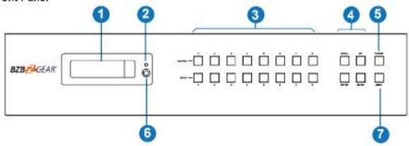
| NO. | Name | Function Description |
| 1 | OLED screen | Display matrix switching status, input / output port, EDID, Baud rate, IP Address. |
| 2 | Power LED | The LED will illuminate green when functioning normally, and red when on standby. |
| 3 | OUTPUT / INPUT buttons | Press an output button (1~8) first, and then press an Input button (1~8) to select the corresponding Input source for the output port. |
| 4 | MENU / ENTER / UP /DOWN | 1EDID setting: On the OLED display screen, press the "MENU" button to enter "Select EDID" interface. Press the "UP/DOWN" button to select the required EDID and press the "ENTER" button to enter "Copy to Input" interface. Then press "UP/DOWN" button to select the input port you need to set. Then press the "ENTER" button again to confirm. 2Baud rate setting: On the OLED display screen, press the "MENU" button twice to enter "SELECT BAUD" interface, and press "UP/DOWN" button to select the required Baud rate, finally press the "ENTER" button to confirm the setting. 3IP Address Check: On the OLED display screen, press the "MENU" button three times to enter the IP interface and check the current IP address, then press "UP/DOWN" button to switch DHCP ON/OFF, finally press the "ENTER" button to confirm the setting. Pressing the "MENU" button again will return to the initial OLED display status. |
| 5 | POWER button | Hold the POWER button for 3 seconds to enter the standby mode. Press the button once to wake up the |
Rear Panel

| No. | Name | Function Description |
| 1 | IR OUT (1-8/ALL) ports | Connect the IR blaster cable: The IR emit signal will come from the "IR IN" port of the HDBaseT Receiver. |
| 2 | IR IN (1-8/ALL) ports | Connect the IR receiver cable: The IR receive signal will emit to the "IR OUT" port of the HDBaseT Receiver. |
| 3 | AUDIO OUT (1-8) ports | 8 groups of coaxial and balanced analog audio mirrored output ports. AUDIO OUT (1-8) follows the video output of OUTPUT (1-8) ports. |
| 4 | CONTROL ports | TCP/IP: The link port for TCP/IP control. Connect to an active Ethernet link with an RJ45 cable. |
| RS-232: Command control port: Connect to a PC or contro system with a D-Sub 9-pln cable to control the Matrix. | ||
| 5 | GND | Connect the housing to the ground. |
| 6 | POWER Input | Power port: Connect to 100~240V AC 50/60Hz power cable.Power switch: Press the switch to the power turn on/off. |
| 7 | OUTPUT (1-8) ports | HDMI output ports: Connect to an HDMI display device such as a TV or monitor using an HDMI cable. |
| HDBT mirrored output ports: Connect to an HDBaseT receiver using a CAT cable. | ||
| 8 | INPUT (1-8) ports | HDMI input ports: Connect to an HDMI source device such as a media player or PS4 using an HDMI cable. |
![graph LR A["Data Signal\nIndicator Lamp"] --> B((Sensor)) C["Connection Signal\nIndicator Lamp"] --> B](/content/2026/06/1247332/images/a52637d6726b9c844e416161537e2892ff78a49733857477297db38c378126ee.jpg)
5.2 HDBaseT Receiver Panel

| No. | Name | Function Description |
| 1 | Power LED | The red LED will illuminate when the receiver is powered on. |
| 2 | SERVICE port | Firmware update port. |
| 3 | DC 24V | DC 24V/1A power supply input port.Note: The Matrix supports POC function which means that either the transmitter or receiver is powered on by 24V/1A power adapter, and the corresponding unit doesn't require power. |
| 4 | HDBT IN | RJ45 connector for connecting the HDBT OUTPUT port of Matrix with a CAT cable. |
| 5 | Connection Signal Indicator lamp | Illuminating: Matrix and Receiver has a good connection.Flashing: Matrix and Receiver has a poor connection.Dark: Matrix and Receiver are not connected. |
| 6 | Data Signal Indicator | Illuminating: HDMI signal with HDCP.Flashing: HDMI signal without HDCP.Dark: No HDMI signal. |
| 7 | HDMI OUT | HDMI output port: Connect to an HDMI display device such as a TV or monitor using an HDMI cable. |
| 8 | AUDIO OUT | Analog audio output port: The audio is extracted from the HDMI signal. |
| 9 | IR IN | Connect the IR receiver cable: The IR receive signal will emit to the "IR OUT" port of the Matrix |
| 10 | IR OUT | Connect the IR blaster cable: The IR signal will come from the "IR IN" port of the Matrix. |
| 11 | RS-232 | Connect to a PC or control system with a 3-pin phoenix connector cable to transmit commands between the Matrix and HDBaseT Receiver. |
6. IR Remote
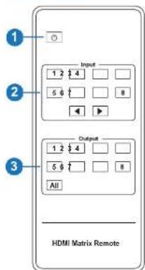
① Power on or Standby: Power on, or set the Matrix to standby mode.
② Input 1/2/3/4/5/6/7/8: Select input source button. ◀ ▶ : Select the last or next input source button.
③ Output 1/2/3/4/5/6/7/8 button: Select output source button.
All: Select all output sources simultaneously. For example, when you press the "All" button and then press input the "1" button, the input "1" source will output to all display devices.
Operation instruction: Press the output button first, then press the input button to select the corresponding input source. For example, press Output-X (X = output button from 1 to 8, including "All" button) Then press Input-Y (Y = input button from 1 to 8).
7. IR Control System
The BG-UM88-150L-KIT is not only a matrix switch but also an extender that supports bi-directional IR control. When the Matrix is connected to HDBaseT Receiver through Cat 5e/6/7 cable, the remote display device (HDBaseT), or input source device (Matrix) may be controlled through the IR signal transmission. Note: The IR signal transmission method is different from the method from Matrix (local) to HDBaseT Receiver (remote) and from HDBaseT Receiver (remote) to Matrix (local).
At the Matrix end (Local end): the IR signal is one-to-one transmission. For example, the IR IN 1 port signal of the Matrix will emit to IR OUT port of the HDBaseT Receiver 1, and the IR IN 3 port signal of the Matrix will emit to IR OUT port of the HDBaseT Receiver 3. It does not follow the video switching. IR IN ALL port signal of the Matrix will emit to all IR OUT ports of HDBaseT receivers simultaneously. Please see the connection diagram below:

At HDBaseT receiver (Remote end): The IR signal follows video switching. For example, the HDMI output signal on the HDBaseT Receiver 1 is from the HDMI INPUT 2 port, so the IR input signal of the HDBaseT Receiver 1 will emit to the IR OUT 2 port of the Matrix. The HDMI output signal on the HDBaseT Receiver 5 is from the HDMI INPUT 4 port. The IR input signal of the HDBaseT Receiver 5 will emit to the IR OUT 4 port of the Matrix etc. Any of the HDBaseT Receiver's IR IN signals can output from the IR OUT ALL port of the Matrix. The IR OUT ALL signal of the Matrix depends on the IR remote of the source device. Please see the connection diagram below:

Figure 2: IR connection diagram (HDBaseT Receiver end)
8. IR Cable Pin Assignment

9. EDID Management
The Matrix has 21 factory defined EDID settings, 2 user-defined EDID modes, and 16 copy EDID modes. Select "defined EDID" mode, or "copy EDID" mode to input port through on-panel button, RS-232 control or Web GUI.
On-panel button operation: On the initial OLED display screen, press the "MENU" button to enter the EDID setting interface. Press the "UP/DOWN" button to select the required EDID, and press the "ENTER" button to enter "Copy to Input:" interface. Press the "UP/DOWN" button to select the specific input port to set, then press "ENTER" button again to confirm this operation.
RS-232 control operation: Connect the Matrix to a PC with a serial cable. Open a

The defined EDID settings list of the product is shown below:
| EDID Mode | EDID Description |
| 1 | 1080p, Stereo Audio 2.0 |
| 2 | 1080p, Dolby/DTS 5.1 |
| 3 | 1080p, HD Audio 7.1 |
| 4 | 1080i, Stereo Audio 2.0 |
| 5 | 1080i, Dolby/DTS 5.1 |
| 6 | 1080i, HD Audio 7.1 |
| 7 | 3D, Stereo Audio 2.0 |
| 8 | 3D, Dolby/DTS 5.1 |
| 9 | 3D, HD Audio 7.1 |
| 10 | 4K2K30_444, Stereo Audio 2.0 |
| 11 | 4K2K30_444, Dolby/DTS 5.1 |
| 12 | 4K2K30_444, HD Audio 7.1 |
| 13 | 4K2K60_420, Stereo Audio 2.0 |
| 14 | 4K2K60_420, Dolby/DTS 5.1 |
| 15 | 4K2K60_420, HD Audio 7.1 |
| 16 | 4K2K60_444, Stereo Audio 2.0 |
| 17 | 4K2K60_444, Dolby/DTS 5.1 |
| 18 | 4K2K60_444, HD Audio 7.1 |
| 19 | 4K2K60, Stereo Audio 2.0 HDR |
| 20 | 4K2K60, Dolby/DTS 5.1 HDR |
10. WebGUI User Guide
The Matrix may be controlled by using a WebGUI. The operation method is shown below: Step 1: Find the current IP Address.
The default IP address is 192.168.1.100. The current Matrix IP address may be found in two ways:
1: Find the IP address via panel buttons. On the initial OLED display, press the "MENU" button three times to enter the IP interface and check the current IP address.
2: Find the IP address via RS-232 control. Send the ASCII command "r ipconfig!" through a Serial Command tool, the following information will then populate:
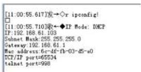
IP:192.168.61.103 In the figure above is the current Matrix IP address (this IP address is variable, depending on what the specific machine returns).
For the details of RS-232 control, please refer to section 11 of this manual.
Step 2: Connect the TCP/IP port of the Matrix to a PC using a UTP cable (as shown in the following figure), and set the IP address of the PC to be in the same network segment with the Matrix.

PC
Step 3: Input the current IP address of the Matrix into the PC's browser to enter WebGUI page.
http://1921682.1/#/loalr
e 6 v
After entering the WebGUI page, the following login page will be displayed:

Select the username from the list and enter the password. The default login information:
Username User Admin
Password user admin
After entering the password, click the "LOGIN" button and the following Status page will display.
■ Status Page
The Status page provides basic information about the product model, installed firmware version, and the network settings of the device.

■ Video Page

The following operations may be performed on the Video page:
① Output: The current OUTPUT port of the device. The input signal source may be selected.
② Input: Click the drop-down menu to select the input source for the corresponding OUTPUT port.
③ Presets Name: Name the current scene with maximum length of 12 characters
④ Presets Set: Restore the settings of the last saved audio-video matrix switching relationship.
⑤ Presets Save: Save audio-video matrix switching configuration.
⑥ Presets Clear: Clear the saved audio-video matrix switching configuration.
■ Input Page

The following operations may be performed on the Input page:
⑤ Input: Input channel of the dusing
Set EDID for the User
Click the "Browse" button, then select the bin file. Selecting the wrong EDID file will cause the prompt below to display:

Select the correct file, then check the name of the selected file. Select "User 1" or "User 2", then click "Upload". After successful setting, the prompt below to display:

Download the EDID File for the Corresponding Input Channel
Click the drop-down box of "Select EDID File" to select the corresponding input channel. Then click "Download" to download the corresponding EDID file.
■ Output Page

The following operations may be performed on the Output page:
① Outputs: Output channel of the device.
② Name: The current output channel's name. Modify the name by entering the corresponding name (max length: 12 characters) in the input box
■ CEC Page

Perform the CEC management on this page:
① Input Control: Control the operation of each input source by pressing the icons on the
page. Multiple inputs may be controlled simultaneously
② Output Control: Control the operation of each display, such as power on/off, volume
+/-, and active source switching. Multiple outputs may be controlled simultaneously.
■ Network Page
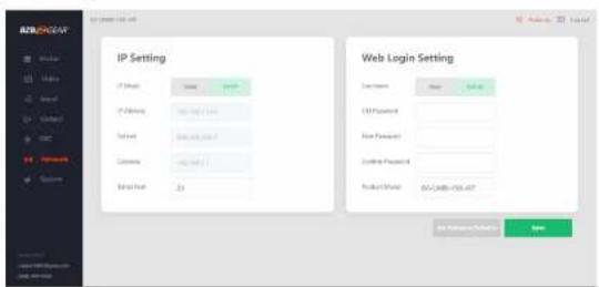
Set the Default Network
Select "Set Network Defaults" button and the prompt below will display:

Click "OK" to search the IP Address again, as shown in the figure below:

After searching has completed, it will switch to the login page, and the default network setting has been completed.
Modify User Password
Click the "User" button, enter the correct Old Password, New Password, and Confirm Password, then click "Save". After successfully modifying, the following prompt will display:

Note: Rules for changing passwords:
(1) The password cannot be empty.
(2) New password cannot be the same as old password.
(3) New password and confirm password must be the same.
Modify Network Setting
Modify the Mode/IP Address/Gateway/Subnet Mask/Telnet Port as required, click "Save" to save the settings.
After modification, if the Mode is "Static", it will switch to the corresponding IP Address;
If the Mode is "DHCP", it will automatically search and switch to the IP Address assigned by the router.

■ System Page
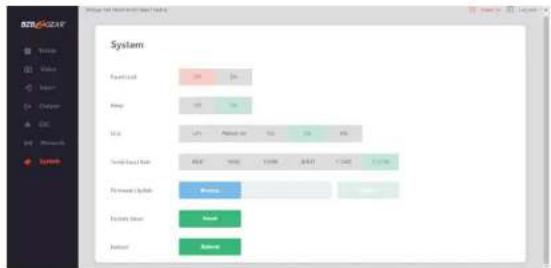
① Panel Lock: Click to lock/unlock panel buttons. "On" indicates that panel buttons are unavailable; "Off" indicates panel buttons are available.
② Beep: Click to turn on/off the beep.
③ LCD: Turn the LCD on/off, and set the turn-on time (15s/30s/60s).
④ Serial Baud Rate: Click the value to set the Serial Baud Rate.
⑤ Firmware Update: Click "Browse" to select the update file, then click "Update" to complete firmware update.
⑥ Factory Reset: Reset the device to factory defaults by clicking "Reset".
⑦ Reboot: Reboot the machine by clicking "Reboot".
Note: After reset/reboot, it will switch to the login page.
11. RS-232 Control Command
The BG-UM88-150L-KIT supports RS-232 control. A serial cable with RS-232 male head and DB9 transfer USB male head is required. The RS-232 head of the serial cable is connected to the RS-232 control port with DB 9 at the rear of the Matrix, and the USB head of the serial cable is connected to a PC. The connection method is as follows:

Open a Serial Command tool on a PC to send ASCII command to control the Matrix.
The ASCII command list is given below:
| ASCII Command | ||||
| Serial port protocol. Baud rate: 115200, Data bits: 8bit, Stop bits:1, Check bit: 0 | ||||
| x - Parameter 1y - Parameter 2I - Defimator | ||||
| Command Code | Function Description | Example | Feedback | Default Setting |
| Power | ||||
| s power z! | Power on/off the device,z=0-1(z=0 power off, z=1 power on) | s power 1! | Power onSystem Initializing...Initialization Finished!FW version x.xx.xx | power on |
| r power! | Get current power slate | r power! | power on/power off | |
| s reboot! | Reboot the device | s reboot! | Reboot...System Initializing...Initialization Finished!FW version x.xx.xx | |
| System Setup | ||||
| help! | List all commands | help! | ||
| r type! | Get device model | r type! | HDP-MXB88H150 | |
| r status! | Get device current status | r status! | Get the unit all status:power, beep, lock, in/out connection. | |
| Command Code | Function Description | Example | Feedback | Default Setting |
| r link in x! | Get the connection status of the x input port. x=0-8(0=all) | r link in 1! | hdmi input 1: connected | |
| r link out y! | Get the connection status of the y output port. y=0-8(0=all) | r link out 1! | hdmi output 1: connect hdmi output 1: connected | |
| s reset! | Reset to factory defaults | s reset! | Reset to factory default System initializing... Initialization Finished! FW version x.xx.xx | |
| a beep z! | Enable/Disable buzzer function, z=0-1(z=0 beep off, z=1 beep on) | a beep 1! | beep on beep off | beep on |
| r beep! | Get buzzer state | r beep! | beep on / beep off | |
| a lock z! | Lock/Unlock front panel button. z=0-1 (z=0 lock off,z=1 lock on) | a lock 1! | panel button lock on panel button lock off | panel button lock off |
| r lock! | Get panel button lock state | r lock! | panel button lock on/off | |
| a lod on time z! | Set LCD screen remain on time. z=0-4 (0/off 1:always on, 2:15s, 0:30s, 4:60s) | a lod on time 1! | lod always on | lod on 30 seconds |
| r lod model | Get the backlight status of lod screen | r lod mode! | lod always on | |
| a save preset z! | Save switch state between all output port and the input port to preset z. z=1-8 | a save preset 1! | save to preset 1 | |
| a recall preset z! | Call saved preset z scenarios z=1-8 | a recall preset 1! | recall from preset 1 | |
| a clear preset z! | Clear stored preset z scenarios, z=1-8 | a clear preset 1! | clear preset 1 | |
| r preset z! | Get preset z information, z=1-8 | r preset 1! | video/audio crosspoint | |
| a logo1 (unknown) | Set the logo name displayed on the first line of LCD screen, the max character is 16 | s logo1 Matrix Switch! | logo1 Matrix Switch | |
| a baud rate xxx! | Set the serial port baud rate of RS02 module. z=(115200,57500, 35400,19200,9600,4800) | s baud rate 115200! | Baudrate:115200 | 115200 |
| r baud rate! | Get the serial port baud rate of RS02 module | r baud rate! | Baudrate:115200 | |
| s id z! | Set the control ID of the product. z=000-999 | s id 888! | id 868 | 0 |
| Output Setting | ||||
| a in x av out y! | Set input x to output y, x=1-8. y=0-8(0=all) | a in 1 av out 2! | Input 1 -> output 2 | ptp |
| r av out y! | Get output y signal status y=0-6(0=all) | r av out 0! | input 1 -> output 1 Input 2 -> output 2 ..... Input 8 -> output 8 | |
| s hdmi y stream z! | Set hdmi output y stream on/off, y=0-6(0=all) | s hdmi 1 stream 1! | enable hdmi output 1 stream disable hdmi output 1 stream | enable |
| s hdt y stream z1 | Sel hdt output y stream on/off,y=0~8(0-all)z=0~1(0:disable,1:erable) | s hdt 1 stream 1s hdt 0 stream 1 | enable hdt output 1streamdisable hdt output 1streamonable hdt all outputsstreamdisable hdt all outputssstream | onalo |
| r hdt y stream! | Get hdt output y stream status,y=0~8(0-all) | r hdt 1 stream! | onable hdt output 1stream | |
| s hdm i y scaler z1 | Set hdm i output y port outputscaler mode,y=0~8(0-all),z=1~3(1-bypass,2=4k->1080p,3=Auto) | s hdm i scaler 11s hdm i 0 scaler 11 | hdm i output 1 set tobypass modehdm i all outputs set tobypass mode | hdm i all outputsset to bypassmode |
| r hdm i y scaler! | Get hdm i output y port outputmode y=0~8(0-all) | r hdm i scorer | hdm i output 1 set tobypass mode | |
| s hdt y scaler z1 | Set hdt output y port outputscaler mode,y=0~8(0-all),z=1~3(1-bypass,2=4k->1080p,3=Auto) | s hdt 1 scaler 11s hdt 0 scaler 11 | hdt i output 1 set tobypass modehdt i all outputs set tobypass mode | hdt all outputsset to bypassmode |
| r hdt y scaler ! | Get hdt output y port outputmode y=0~8(0-all) | r hdt 1 scorer ! | hdt i output 1 set tobypass mode | |
| EDID Setting | ||||
| s edid in x from z1 | Set input x EDID from defaultEDID x=0~8(0-all),z=1~391.1080p Stereo Audio 2.02.1080p,Dolby/CTS 5.13.1080p.HD Audio 7.14.1080p.Stereo Audio 2.05.1080p.Dolby/CTS 5.16.1080p.HD Audio 7.17.3D.Stereo Audio 2.08.3D.Dolby/CTS 5.19.3D.HD Audio 7.110.4K2K60_444.Stereo Audio 2.011.4K2K30_444.Dolby/CTS 5.112.4K2K30_444.HD Audio 7.113.4K2K60_420.Stereo Audio 2.014.4K2K60_420.Dolby/CTS 5.115.4K2K60_420.HD Audio 7.116.4K2K60_444.Stereo Audio 2.017.4K2K60_444.Dolby/CTS 5.118.4K2K60_444.HD Audio 7.119.4K2K60_444.Storoo Audio 2.0HDR20.4K2K60_444.Dolby/CTS 5.1HDR21.4K2K60_444.HD Audio 7.1HDR22.User define123.User define224-31,copy from hdmi output 1-832-59,copy from hdt output 1-8 | input 1 EDID:1060p,Stereo Audio 2.0all inputs EDID:1080p,Stereo Audio 2.0 | 1080p,Stereo Audio 2.0 | |
| r oxid data hdmi y! | Get the EDID data of the hdmi output y port, y-1-8 | r oxid data hdmi 1! | input1 EDID:4K2K60_444,Stereo Audio 2.0EDID: 00 FF FF FF FF FF FF 00 ...... | |
| r oxid data hbot y! | Got the EDID data of the hbot output y port, y-1-8 | r oxid data hbot 1! | EDID: 00 FF FF FF FF FF FF 00 ...... | |
| CEC Setting | ||||
| s cec in x on! | set input x power on by CEC, x-0-8(0-all input) | s cec in 1 on! | input 1 power on | |
| s cec in x off! | set input x power off by CEC, x-0-8(0-all input) | s cec in 1 off! | input 1 power off | |
| s cec in x menu! | set input x open menu by CEC, x-0-8(0-all input) | s cec in 1 menu! | input 1 open menu | |
| s cec in x play! | set input x play by CEC, x-0-8(0-all input) | s cec in 1 play! | input 1 play operation | |
| s cec in x pause! | set input x pause by CEC, x-0-8(0-all input) | s cec in 1 pause! | input 1 pause operation | |
| s cec in x stop! | set input x stop by CEC, x-0-8(0-all input) | s ooc in 1 stop! | input 1 stop operation | |
| s cec in x new! | set input x rewind by CEC, x-0-8(0-all input) | s cec in 1 new! | input 1 rewind operation | |
| s cec in x mute! | set input x volume mute by CEC, x-0-8(0-all input) | s ooc in 1 mute! | input 1 volume mute | |
| s cec in x vol-! | set input x volume down by CEC, x-0-8(0-all input) | s ooc in 1 vol-! | input 1 volume down | |
| s cec in x vol-! | set input x volume up by CEC, x-0-8(0-all input) | s cec in 1 vol-! | input 1 volume up | |
| s cec in x ff! | set input x fast forward by CEC, x-0-8(0-all input) | s ooc in 1 ff! | input 1 fast forward operation | |
| s cec in x previous | set input x previous by CEC, x-0-8(0-all input) | s ooc in 1 previous | input 1 previous operation | |
| s cec in x next! | set input x next by CEC, x-0-8(0-all input) | s cec in 1 next! | input 1 next operation | |
| s cec hdmi cut y on! | set hdmi output y power on by CEC, y-0-8(0-all hdmi output) | s cec hdmi out 1 on! | hdmi output 1 power on | |
| s ooc hbot out y on! | set hbot output y power on by CEC, y-0-8(0-all hbot output) | s ooc hbot out 1 on! | hbot output 1 power on | |
| s cec hdmi cut y off! | set hdmi output y power off by CEC, y-0-8(0-all hdmi output) | s cec hdmi out 1 off! | hdmi output 1 power off | |
| s ooc hbot out y off! | set hbot output y power off by CEC, y-0-8(0-all hbot output) | s ooc hbot out 1 off! | hbot output 1 power off | |
| s ooc hdmi out y mute! | set hdmi output y volume mute by CEC, y-0-8(0-all hdmi output) | s ooc hdmi out 1 mute! | hdmi output 1 volume mute | |
| s cec hbot out y mute! | set hbot output y volume mute by CEC, y-0-8(0-all hbot output) | s cec hbot out 1 mute! | hbot output 1 volume mute | |
| s cec hdmi cut y vol-! | set hdmi output y volume down by CEC, y-0-8(0-all hdmi output) | s cec hdmi out 1 vol-! | hdmi output 1 volume down | |
| s ooc hbot out y vol-! | set hbot output y volume down by CEC, y-0-8(0-all hbot output) | s ooc hbot out 1 vol-! | hbot output 1 volume down | |
| s oec hdmi out yNetwork Setting | set hdmi output y volume up by | s ooc hdmi out 1 | hdmi output 1 volume | |
| r ipconfig! | Get the Current IP Configuration | r ipconfig! | IP Mode: StaticIP: 192.168.1.72Subnet Mask:255.255.255.0Gateway: 192.168.1.1TCP/IP port-6000Telnet port-10Mac address:00:1C91.03:80:01 | |
| r mac addr! | Get network MAC address | r mac addr! | Mac address:00:1C.91.03:80:01 | |
| s ip mode z! | Set network IP mode to static IP or DHCP,z-0~1 (z-0 Static, z-1 DHCP) | s ip mode 0! | Set IP mode:Static(Please use "s net reboot" command or repower device to apply new config!) | |
| r ip model! | Get network IP mode | r ip model! | IP Mode: Static | |
| s ip addrxxx.xxx.xxx.xxx! | Set network IP address | s ip addr192.166.1.100! | Set IP address:192.168.1.100 (Please use "s net reboot" command or repower device to apply new config!)DHCP on, Device can't config static address,set DHCP off first. | |
| r ip addr! | Get network IP address | r ip addr! | IP: 192.168.1.100 | |
| s subnetxxx.xxx.xxx.xxx! | Set network subnet mask | s subnet255.255.255.0! | Set subnet Maskaddress:255.255.255.0(Please use "s net reboot" command or repower device to apply new config!)DHCP on, Device can't config subnet mask,set DHCP off first. | |
| r subnet! | Get network subnet mask | r subnet! | Subnet Mask:255.255.255.0 | |
| s gatewayxxx xxx xxx xxx! | Set network gateway | s gateway192.166.1.1! | Set gateway:192.168.1.1Please use "s net reboot" command or repower device to apply new config!DHCP on, Device can't config gateway, set DHCP off first. | |
| r gateway! | Get network gateway | r gateway! | Gateway: 192.168.1.1 | |
| s tcpip port x! | Set network TCP/IP port(x=1-60635) | s tcpip port 8000! | Set TCP/IP port:8000 | |
| r top ip port! | Get network TCP/IP port | r top ip port! | TCP/IP port:8000 | |
| s net reboot! | Reboot network modules | s net reboot! | Network rebootIP Mode: StaticIP: 192.168.1.72Subnet Mask255.255.255.0Gateway: 192.168.1.1TCP/IP port=5000Tolnot port=10Mac address:00:10:91:03:80:01 | |
| a uart x datalen y! | Set the data length of x hdtut uart,x=0-8,y=1-2,1:8ot 2:7bit | a uart 1 datalen 1! | hdtut uart1 data len is bot | |
| s uart x baudrale y! | Sel the baudrate of x hdtut uart,x=0-8,y=1-8,1:115200(Default)2: 57600 3: 56000 4:384005:19200 8:14400 7:9600 8:4800 | s uart 1baudrate 1! | hdtut uart1 baudrate is 115200 | |
| s uart x parity y! | Set the Parity of x hdtut uart,x=0-8,y=1-31:none 2 odd 3:ovcn | s uart x parity 1! | hdtut uart1 parity is none | |
| a uart x type zsenodata y end! | Send data y from x hdtut uart,z=0 ascll,z=1 hex,x=0-8 | s uart 1 type 0senodata abodefgend! | hdtut uart1 data:abodefg | |
| r uart status x! | Get the Status of x hdtut uart,x=0-8 | r uart status 1! | hdtut uart1 baudrate 9500.daten Bot,parity none | |
12. Application Example
![graph TD A["PC"] --> B["Power Supply"] B --> C["TV Box"] C --> D["TV"] D --> E["TV"] E --> F["Power Supply"] F --> G["PC"] G --> H["Power Supply"] H --> I["TV Box"] I --> J["TV"] J --> K["Power Supply"] K --> L["PC"] L --> M["Power Supply"] M --> N["TV Box"] N --> O["TV"] O --> P["Power Supply"] P -…](/content/2026/06/1247332/images/6e0a3ad173f6394eb114b364401c6da02bf7355fdd3072f4c20a3abd666fc464.jpg)
13. Tech Support
Before contacting tech support, we may have answered your question already! Visit our BZBGEAR support page (bzbgear.com/support) for valuable information on our products.
Here you will find our Knowledge Base (bzbgear.com/knowledge-base) consisting of tutorials, quick start guides, and step-by-step troubleshooting instructions. Also visit our YouTube channel BZB TV (youtube.com/c/BZBTVchannel) for help setting up, connecting, and other how-to videos regarding our products.
If you still need help, please call 1.888.499.9906, email support@bzbgear.com, or chat at bzbgear.com.
14. Warranty
BZBGEAR Pro AV products and Cameras come with a three-year warranty. An extended two-year warranty is available for our Cameras upon registration for a total of five years.
For an extended two-year warranty on our Cameras, follow these steps:
- Register your Camera within 90 days of purchase by visiting bzbgear.com/warranty.
- Complete the registration form. Provide all necessary proof of purchase details, including serial number and a copy of your sales receipt.
For complete warranty information, please visit bzbgear.com/warranty or scan the QR code.

Mission Statement
BZBGEAR manifests from the competitive nature of the audiovisual and live streaming industry to innovate while keeping the customer in mind. AV solutions can cost a pretty penny, and new technology only adds to it. We believe everyone deserves to see, hear, and feel the advancements made in today's AV world without having to break the bank. BZBGEAR is your answer for applications requiring the latest pro AV and live streaming solutions.
You'll notice comparably lower prices with BZBGEAR while the performance and quality are on par with the top brands in the industry. Our team offers system design consultation and expert tech support seven days a week for all BZBGEAR products. Our unparalleled support is our way of showing we care for every one of our customers. Whether you're an integrator, home theater enthusiast, or a do-it-yourselfer, BZBGEAR offers solutions allowing you to focus on your project and not your budget.

- THANK YOU FOR PURCHASING THIS PRODUCT
- SURGE PROTECTION DEVICE RECOMMENDED
- TABLE OF CONTENTS
- INTRODUCTION
- FEATURES
- PACKAGE CONTENTS
- OPERATION CONTROLS AND FUNCTIONS
- 5.1 MATRIX PANEL
- IR REMOTE
- IR CONTROL SYSTEM
- IR CABLE PIN ASSIGNMENT
- EDID MANAGEMENT
- WEBGUI USER GUIDE
- STATUS PAGE
- SET EDID FOR THE USER
- DOWNLOAD THE EDID FILE FOR THE CORRESPONDING INPUT CHANNEL
- OUTPUT PAGE
- MODIFY USER PASSWORD
- MODIFY NETWORK SETTING
- SYSTEM PAGE
- RS-232 CONTROL COMMAND
- APPLICATION EXAMPLE
- TECH SUPPORT
- WARRANTY
- MISSION STATEMENT
Brand : BZBGear
Model : BG-UM88-150L
Category : Gps