
VZ-097RTLD - Surveillance ViewZ - Free user manual and instructions
Find the device manual for free VZ-097RTLD ViewZ in PDF.


| Product Type | Surveillance Monitor |
| Display Size | 9.7 inches diagonal |
| Display Technology | AM-TFT (Active-Matrix) |
| Resolution | 1024 x 768 @ 60 Hz |
| Brightness | 300 cd/m² (typical) |
| Contrast Ratio | 600:1 (typical) |
| Response Time | 35 ms (typical) |
| Horizontal Frequency | 31 - 48 kHz |
| Vertical Frequency | 56 - 60 Hz |
| Pixel Pitch | 0.192 mm (H) x 0.192 mm (V) |
| Active Display Area | 196.608 mm (H) x 147.456 mm (V) |
| Input Signal | VGA (RGB-PC), DVI (Digital Video Interface) |
| Audio Input/Output | Audio In, Audio Out |
| Power Consumption (On) | < 8.2 W |
| Power Consumption (Standby) | < 1 W |
| Power Supply | DC 12V |
| VESA Mount | 75 mm x 75 mm (optional wall mount) |
| Dimensions (W x D x H) | 335 mm x 280 mm x 100 mm (13.19" x 11.02" x 3.94") |
| Weight (Net) | 1.11 kg (2.45 lbs) |
| Package Dimensions | 335 mm x 280 mm x 100 mm |
| OSD Languages | English, Korean, French, Deutsch, Spanish |
| Compliance | FCC Class A, DOC, SEMKO, MPR II |
| Cleaning Instructions | Clean only with dry cloth |
| Safety Features | Polarized plug, grounding type plug, ventilation openings, avoid water and heat sources |
Frequently Asked Questions - VZ-097RTLD ViewZ
User questions about VZ-097RTLD ViewZ
0 question about this device. Answer the ones you know or ask your own.
Ask a new question about this device
Download the instructions for your Surveillance in PDF format for free! Find your manual VZ-097RTLD - ViewZ and take your electronic device back in hand. On this page are published all the documents necessary for the use of your device. VZ-097RTLD by ViewZ.
USER MANUAL VZ-097RTLD ViewZ
natural_image
Front view of a black CRT television displaying a blank screen with control buttons at the bottom (no visible text or symbols on screen)CONTENTS
SAFETY INSTRUCTION 2\~3
CAUTIONS 4
FCC RF INTERFERENCE STATEMENT 5
CONNECTING WITH EXTERNAL EQUIPMENT 6
CONTROLS AND FUNCTIONS 7 \~ 14
MOUNTING GUIDE 15
D-SUB CONNECTOR PIN ASSIGNMENTS 16
POWER MANAGEMENT 17
SPECIFICATIONS 18
TROUBLE SHOOTING GUIDE 19
SAFETY INSTRUCTION
Important Safety Instruction
- Read these instructions.
- Keep these Instructions.
- Heed all warnings.
- Follow all instructions.
- Do not use this apparatus near water.
- Clean only with dry cloth.
- Do not block any ventilation openings. Install in accordance with the manufacturer's instructions.
- Do not install near any heat sources such as radiators, heat registers, stoves, or other apparatus (including amplifiers) that produce heat.
- Do not defeat the safety purpose of the polarized or grounding-type plug.
Apolarized plug has two blades with one wider than the other.
Agrounding type plug has two blades and a third grounding prong.
The wide blade or the third prong are provided for your safety.
If the provided plug does not fit into your outlet, consult an electrician for replacement of the bsolete outlet. - Protect the power cord from being walked on or pinched particularly at plugs, convenience receptacles and the point where they exit from the apparatus.
SAFETY INSTRUCTION
- The apparatus shall not be exposed to dripping or splashing and that no objects filled with liquids, such as vases, shall be placed no the apparatus.
- Minimum distances(e.g. 10cm) around the apparatus for sufficient ventilation.
"WARNING – To reduce the risk of fire or electric shock, do not expose the apparatus to rain or moisture."
"The apparatus shall not be exposed to dripping or splashing and no objects filled with liquids, such as vases, shall be placed on the apparatus."


This symbol is intended to alert the user to the presence of uninsulated : dangerous voltage with in the product's enclosure that may be of sufficient
CAUTIONS
CAUTION
The power supply cord is used as the main disconnect device, ensure that the socket-outlet is located/installed near the equipment and is easily accessible.
ATTENTION
POWER SUPPLY CORD IS USED AS MAIN POWER DISCONNECT DEVICE IN THIS PRODUCT. UNPLUG THIS PRODUCT FROM THE WALL OUTLET BEFORE REMOVING THE BACK COVER AND SERVICING
EMISSION CHARACTERISTICS TESTED BY SEMKO
THIS PRODUCT HAS BEEN TESTED AND HAS SHOWN COMPLIANCE WITH THE NATIONAL SPECIFICATIONS SUCH AS SWEDISH MPR 1990.10.(MPR II)
▶ NEVER REMOVE THE BACK COVER
Removal of the back cover should be carried out only by qualified personnel.
▶ DO NOT USE IN HOSTILE ENVIRONMENTS
To prevent shock or fire hazard, do not expose the unit to rain or moisture.
This unit is designed to be used in the office or home. Do not subject the unit to vibrations,
FCC RF INTERFERENCE STATEMENT
NOTE
This equipment has been tested and found to comply with the limits for a Class A digital device, pursuant to Part 15 of the FCC Rules. These limits are designed to provide reasonable protection against harmful interference in a residential installation.
This equipment generates, uses and can radiate radio frequency energy and, if not installed and used in accordance with the instructions, may cause harmful interference to radio communications. However, there is no guarantee that interference will not occur in a particular installation.
If this equipment does cause harmful interference to radio or television reception which can be determined by turning the equipment off and on, the user is encouraged to try to correct the interference by one or more of the following measures.
- Reorient or relocate the receiving antenna.
- Increase the separation between the equipment and receiver.
- Connect the equipment into an outlet on a circuit different from that to which the receiver is connected.
- Consult the dealer or an experienced radio, TV technician for help.
- Only shielded interface cable should be used.
Finally, any changes or modifications to the equipment by the user not expressly approved by the grantee or manufacturer could void the users authority to operate such equipment.
▶ DOC COMPLIANCE NOTICE
CONNECTING WITH EXTERNAL EQUIPMENT
A. BACK
- AUDIO OUT.
- AUDIO IN.
- VGA.
- DVI.
- DC 12V.

CONTROLS AND FUNCTIONS
B. FRONT

1. INPUT
Selects VGA or DVI inputs.
Selects an option in the OSD.
2. MENU
Activates or exits the OSD.
Moves previous menu or status in the OSD.
3,4. ▲ / ▼
Moves another option in the OSD.
The ▼ button is auto adjustment function in the VGA input.
5, 6. ◀ / ▶
Adjusts the volume and menu settings.
CONTROLS AND FUNCTIONS
OSD Menu Description
All picture, sound settings and setup for the monitor can be adjusted in the OSD menu.
To adjust the OSD screen:
- Press the MENU button to enter the OSD menu.
- Press the ▲/▼ buttons to select the desired option. The selected option is yellow color.
- Press the INPUT button twice to enter the sub-menu and adjust the item.
Change the value you wish to adjust by using the ◀/▶ buttons.
4. Press the MENU button twice to exit the sub-menu and the adjusted item.
5. Press the MENU button again to exit the OSD menu.
A. Color

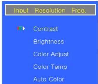
CONTROLS AND FUNCTIONS
B. Image Setting


| Option | Function | Value |
| Clock ^1) | Adjusts the vertical noise of screen image. | 0 ~ 100. |
| Phase ^1) | Adjusts the number of horizontal picture elements. | 0 ~ 60. |
CONTROLS AND FUNCTIONS
C. Position (Only VGA input)
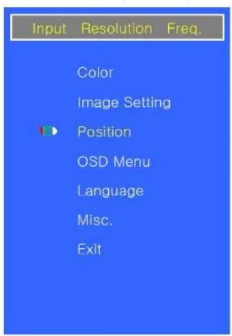
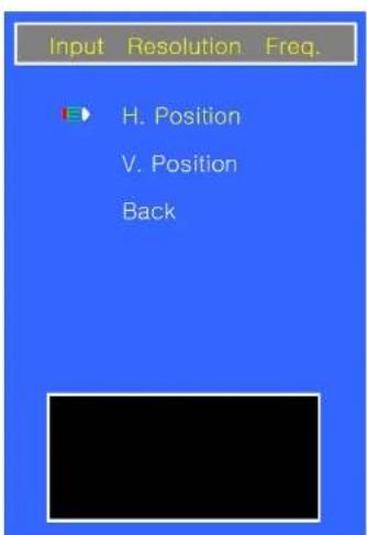
| Option | Function | Value |
| H. Position | Adjusts the horizontally picture position. | 0 ~ 100. |
| V. Position | Adjusts the vertically picture position. | 0 ~ 100. |
CONTROLS AND FUNCTIONS
D. OSD Menu


| Option | Function | Value |
| OSD H. Pos. | Moves the horizontally OSD position. | 0 ~ 100. |
| OSD V. Pos. | Moves the vertically OSD position. | 0 ~ 100. |
CONTROLS AND FUNCTIONS
E. Language


| Option | Function | Value |
| Language | Sets the language of OSD menu. | English, Korean, French, Deutsch & Spanish. |
CONTROLS AND FUNCTIONS
F. Misc.
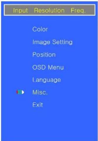

| Option | Function | Value |
| Signal Source | Converts the signal source. | VGA & DVI. |
| Volume | Adjust the level of audio volume. | 0 ~ 100. |
CONTROLS AND FUNCTIONS
G. Exit

| Option | Function |
| Exit | Exits the OSD menu. |
MOUNTING GUIDE
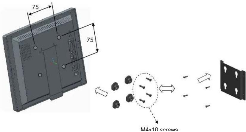
A. Wall mount (Option)
1) Using the 75 mm VESA holes.
2) Using the VESA standard wall mount design and the 75mm hole pattern on the back side to install the LED monitor to the wall.
D-SUB CONNECTOR PIN ASSIGNMENTS
▶ PIN ASSIGNMENTS
This monitor features a power management system to "power down" upon receipt of the VESA DPMS(The display power management signaling) from a VESA DPMS video card.
The VESA DPMS-compliant video card performs this signaling system through not sending horizontal, vertical, or sync signal.
This monitor enters an appropriate mode through identifying each of the three modes of the signaling system.
Power Consumption
| Mode | Power Consumption |
| Turned On | < 8.2W |
| No Signal & Turned Off | < 1W |
LED Indicator
The power management feature of the monitor is comprised of three stages: Turned on(Green), no signal(Red) and turned off(LED off).
| Mode | LED | Monitor Operation |
| Turned On | Green | Normal Operation |
| No Signal | Red | Not Operation |
SPECIFICATIONS
| 9.7" | |
| LED-Type | 9.7" Diagonal AM-TFT(Active-Matrix) |
| Pixel pitch(mm) : 0.192(H) x 0.192(V) | |
| Brightness: 300cd/m2 (Typical) | |
| Contrast Ratio: 600:1(Typical) | |
| Response Time: 35msec(Typical) | |
| RESOLUTION (H x V) | 1024x768 @60Hz |
| FREQUENCY | HORIZONTAL : 31~48KHz,VERTICAL : 56~60Hz |
| INPUT SIGNAL | DVI (Digital Video Interface) |
| VGA (RGB-PC) | |
| AUDIO IN & OUT | |
| ACTIVE DISPLAY AREA (H x V) | 196.608mm x 147.456mm |
| PACKING DIMENSIONS (W x D x H) | 335mm x 280mm x 100mm(13.19" x 11.02" x 3.94") |
| WEIGHT | Net: 1.11kg (2.45 lbs) |
TROUBLESHOOTING GUIDE
| TROUBLE | TROUBLESHOOTING TIP |
| No image on display screen | 1. Check that power cord of the Monitor have been connected securely into wall outlet or grounded extension cable or strip.2. Power switch should be in the ON position and LED is lit.3. Check that the Brightness and/or the Contrast adjustments of the Display have not been turned down to minimum levels. |
| "NO SIGNAL"message on screen | 1. The signal cable should be completely connected to the video card/computer.2. The video card should be completely seated in its slot and the computer is switched ON. |
| Display image is not centered, too small or too large in PC mode | Push the down key in front side. |
| Vertical or Horizontal noise is present in the picture | Adjust Clock and Phase in the OSD. |
WEEE Symbols
Correct Disposal of This Product (Waste Electrical & Electronic Equipment)
MEMO


- CONTENTS
- SAFETY INSTRUCTION
- Important Safety Instruction
- CAUTIONS
- CAUTION
- ATTENTION
- EMISSION CHARACTERISTICS TESTED BY SEMKO
- ▶ NEVER REMOVE THE BACK COVER
- ▶ DO NOT USE IN HOSTILE ENVIRONMENTS
- FCC RF INTERFERENCE STATEMENT
- NOTE
- ▶ DOC COMPLIANCE NOTICE
- CONNECTING WITH EXTERNAL EQUIPMENT
- BACK
- CONTROLS AND FUNCTIONS
- INPUT
- MENU
- 3,4. ▲ / ▼
- 5, 6. ◀ / ▶
- OSD Menu Description
- Color
- Image Setting
- OSD Menu
- Language
- Misc.
- Exit
- MOUNTING GUIDE
- Wall mount (Option)
- D-SUB CONNECTOR PIN ASSIGNMENTS
- LED Indicator
- TROUBLESHOOTING GUIDE
- WEEE Symbols
Brand : ViewZ
Model : VZ-097RTLD
Category : Surveillance